Recent advances in 3D printing of biomaterials
14
REVIEW Open Access Recent advances in 3D printing of biomaterials Helena N Chia 1 and Benjamin M Wu 1,2,3,4* Abstract 3D Printing promises to produce complex biomedical devices according to computer design using patient-specific anatomical data. Since its initial use as pre-surgical visualization models and tooling molds, 3D Printing has slowly evolved to create one-of-a-kind devices, implants, scaffolds for tissue engineering, diagnostic platforms, and drug delivery systems. Fueled by the recent explosion in public interest and access to affordable printers, there is renewed interest to combine stem cells with custom 3D scaffolds for personalized regenerative medicine. Before 3D Printing can be used routinely for the regeneration of complex tissues (e.g. bone, cartilage, muscles, vessels, nerves in the craniomaxillofacial complex), and complex organs with intricate 3D microarchitecture (e.g. liver, lymphoid organs), several technological limitations must be addressed. In this review, the major materials and technology advances within the last five years for each of the common 3D Printing technologies (Three Dimensional Printing, Fused Deposition Modeling, Selective Laser Sintering, Stereolithography, and 3D Plotting/Direct-Write/Bioprinting) are described. Examples are highlighted to illustrate progress of each technology in tissue engineering, and key limitations are identified to motivate future research and advance this fascinating field of advanced manufacturing. Keywords: 3D Printing, Fused deposition modeling, Selective laser sintering, Stereolithography, Computer-aided tissue engineering, 3D plotting, Bioprinting Introduction The ability to design and fabricate complex, 3D biomed- ical devices is critical in tissue engineering. Applications for 3D biomedical devices are restoration of 3D anatomic defects, the reconstruction of complex organs with intri- cate 3D microarchitecture (e.g. liver, lymphoid organs), and scaffolds for stem cell differentiation. An example of a need is anatomic defects in the craniomaxillofacial complex caused by cancer, trauma, and congenital defects. Proper res- toration of these defects requires functional nerves, vessels, muscles, ligaments, cartilage, bone, lymph nodes and glands. In recent years, various approaches based on tissue en- gineering principles have been explored to regenerate other functional tissues that are relevant to maxillofacial tissue regeneration. In tissue engineering, scaffolds are critical to provide structure for cell infiltration and pro- liferation, space for extracellular matrix generation and remodeling, biochemical cues to direct cell behavior, and physical connections for injured tissue. When making scaffolds, design of the architecture on the macro, micro, and nano level is important for structural, nutrient transport, and cell-matrix interaction conditions [1-3]. The macroarchitecture is the overall shape of the device which can be complex (e.g. patient and organ specificity, anatomical features). The microarchitecture reflects the tissue architecture (e.g. pore size, shape, porosity, spatial distribution, and pore interconnection). The nanoarchi- tecture is surface modification (e.g. biomolecule attach- ment for cell adhesion, proliferation, and differentiation). Although an ideal scaffold will account for all these factors, challenges still exist with biomaterial selection and 3D shape specificity. Biomaterials commonly used are polymers (synthetic and natural), ceramics, and metals. Each biomaterial has specific material and mechanical properties, processing methods, chemical properties, cell- material interactions, and FDA approval. Common fabri- cation methods to produce porosity and a range of pores size are gas foaming, solvent casting with particle leaching, freeze-drying, and eletrospinning. While the microarchi- tecture in these methods is well-controlled and under- stood, the ability to control macroarchitecture with these methods is limited to 3D shapes and geometries deter- mined by molds and manual processing. The ability to * Correspondence: [email protected] 1 Department of Bioengineering, Henry Samueli School of Engineering, University of California, 5121 Engineering V, Los Angeles, CA 90095, USA 2 Department of Materials Science and Engineering, Henry Samueli School of Engineering, University of California, Los Angeles, CA 90095, USA Full list of author information is available at the end of the article © 2015 Chia and Wu; licensee BioMed Central. This is an Open Access article distributed under the terms of the Creative Commons Attribution License (http://creativecommons.org/licenses/by/4.0), which permits unrestricted use, distribution, and reproduction in any medium, provided the original work is properly credited. The Creative Commons Public Domain Dedication waiver (http://creativecommons.org/publicdomain/zero/1.0/) applies to the data made available in this article, unless otherwise stated. Chia and Wu Journal of Biological Engineering (2015) 9:4 DOI 10.1186/s13036-015-0001-4
Transcript of Recent advances in 3D printing of biomaterials

Chia and Wu Journal of Biological Engineering (2015) 9:4 DOI 10.1186/s13036-015-0001-4
REVIEW Open Access
Recent advances in 3D printing of biomaterialsHelena N Chia1 and Benjamin M Wu1,2,3,4*
Abstract
3D Printing promises to produce complex biomedical devices according to computer design using patient-specificanatomical data. Since its initial use as pre-surgical visualization models and tooling molds, 3D Printing has slowlyevolved to create one-of-a-kind devices, implants, scaffolds for tissue engineering, diagnostic platforms, and drugdelivery systems. Fueled by the recent explosion in public interest and access to affordable printers, there isrenewed interest to combine stem cells with custom 3D scaffolds for personalized regenerative medicine. Before3D Printing can be used routinely for the regeneration of complex tissues (e.g. bone, cartilage, muscles, vessels,nerves in the craniomaxillofacial complex), and complex organs with intricate 3D microarchitecture (e.g. liver,lymphoid organs), several technological limitations must be addressed. In this review, the major materials andtechnology advances within the last five years for each of the common 3D Printing technologies (Three DimensionalPrinting, Fused Deposition Modeling, Selective Laser Sintering, Stereolithography, and 3D Plotting/Direct-Write/Bioprinting)are described. Examples are highlighted to illustrate progress of each technology in tissue engineering, and keylimitations are identified to motivate future research and advance this fascinating field of advanced manufacturing.
Keywords: 3D Printing, Fused deposition modeling, Selective laser sintering, Stereolithography, Computer-aided tissueengineering, 3D plotting, Bioprinting
IntroductionThe ability to design and fabricate complex, 3D biomed-ical devices is critical in tissue engineering. Applicationsfor 3D biomedical devices are restoration of 3D anatomicdefects, the reconstruction of complex organs with intri-cate 3D microarchitecture (e.g. liver, lymphoid organs),and scaffolds for stem cell differentiation. An example of aneed is anatomic defects in the craniomaxillofacial complexcaused by cancer, trauma, and congenital defects. Proper res-toration of these defects requires functional nerves, vessels,muscles, ligaments, cartilage, bone, lymph nodes and glands.In recent years, various approaches based on tissue en-
gineering principles have been explored to regenerateother functional tissues that are relevant to maxillofacialtissue regeneration. In tissue engineering, scaffolds arecritical to provide structure for cell infiltration and pro-liferation, space for extracellular matrix generation andremodeling, biochemical cues to direct cell behavior, andphysical connections for injured tissue. When making
* Correspondence: [email protected] of Bioengineering, Henry Samueli School of Engineering,University of California, 5121 Engineering V, Los Angeles, CA 90095, USA2Department of Materials Science and Engineering, Henry Samueli School ofEngineering, University of California, Los Angeles, CA 90095, USAFull list of author information is available at the end of the article
© 2015 Chia and Wu; licensee BioMed CentraCommons Attribution License (http://creativecreproduction in any medium, provided the orDedication waiver (http://creativecommons.orunless otherwise stated.
scaffolds, design of the architecture on the macro, micro,and nano level is important for structural, nutrienttransport, and cell-matrix interaction conditions [1-3].The macroarchitecture is the overall shape of the devicewhich can be complex (e.g. patient and organ specificity,anatomical features). The microarchitecture reflects thetissue architecture (e.g. pore size, shape, porosity, spatialdistribution, and pore interconnection). The nanoarchi-tecture is surface modification (e.g. biomolecule attach-ment for cell adhesion, proliferation, and differentiation).Although an ideal scaffold will account for all these
factors, challenges still exist with biomaterial selection and3D shape specificity. Biomaterials commonly used arepolymers (synthetic and natural), ceramics, and metals.Each biomaterial has specific material and mechanicalproperties, processing methods, chemical properties, cell-material interactions, and FDA approval. Common fabri-cation methods to produce porosity and a range of poressize are gas foaming, solvent casting with particle leaching,freeze-drying, and eletrospinning. While the microarchi-tecture in these methods is well-controlled and under-stood, the ability to control macroarchitecture with thesemethods is limited to 3D shapes and geometries deter-mined by molds and manual processing. The ability to
l. This is an Open Access article distributed under the terms of the Creativeommons.org/licenses/by/4.0), which permits unrestricted use, distribution, andiginal work is properly credited. The Creative Commons Public Domaing/publicdomain/zero/1.0/) applies to the data made available in this article,
Chia and Wu Journal of Biological Engineering (2015) 9:4 Page 2 of 14
incorporate internal architecture or curved channels isalso limited when using these methods.Solid free form fabrication (SFF) has allowed for the de-
sign and fabrication of complex 3D structures which canbe patient specific. The integration of computer aideddesign, advanced imaging techniques (i.e. magnetic reson-ance imaging and computer tomography), and rapidprototyping has advanced fabrication of objects with bothmacro and microarchitecture control. In addition, patientspecific imaging can be used to customize builds for indi-viduals [4,5]. A type of rapid prototyping, SFF offers amethod to control both the micro and macroarchitectureto create complex biomedical devices. Most surface modi-fications can be completed in post-processing. While con-ventional material processing techniques can be highlyeffective in scaffold engineering, SFF technologies offer ex-citing opportunities for tissue engineering of highly com-plex maxillofacial tissues. However, each technology hasits limitations. The selection of the fabrication techniquedepends upon the materials of interest, machine limita-tions, and the specific requirements of the final scaffold.The term “3D Printing” should be clarified to prevent
confusion in this review article. Currently in literatureand mainstream media, the term “3D Printing” is beingused to refer to all SFF technologies (e.g. fused depos-ition modeling, selective laser sintering, etc.). In this re-view, the term will be used in two ways: to generallyrefer to all SFF technologies and to refer to the liquidbinder-based inkjet technology which is described in de-tail below. The use of the term will be clear in the differ-ent sections.The state of the art 3D Printing, especially for the pro-
duction of implantable biomedical devices, is severelylimited by printable materials. Therefore in most cases,alternative material processing methods are required towork with materials that are not easily printed. In caseswhere materials can be printed, 3D Printing is particu-larly advantages for one-of-a-kind, customized complexdevices that are not cost effective in conventional manu-facturing methods such as injection molding.While industrial 3D printers have reached extremely
high resolution in the past few years, the advancementsin machine capability have not translated to the use withbiomaterials. Industrial 3D printers can now reach ex-tremely small build layers such as 16 μm layer thicknessfor SLA (Polyjet, Stratasys), 178 μm layer thickness forFDM (Fortus 900mc, Stratasys), 80 μm layer thicknessfor SLS (sPro 230HS, 3D Systems) and 75 μm resolutionfor SLA (3D Systems). These systems unfortunately arenot optimized for biomaterials of interest for in vitroand in vivo studies and advances are still being made toimprove SFF methods for biomaterials.The cost of each of these technologies is currently dif-
ficult to compare since many advances are based on
home-made setups or modification of commercial ma-chines by creative engineers. Actual cost will be easier tocompare when the materials become available for largescale adaptation for industrial 3D printers. That stagewill also determine the ease of use for both printing andpost-processing. Even with current modeling materials,most printers require some type of sacrificial supportmaterials that require careful removalSFF methods, particularly FDM, have recently ex-
ploded in popularity and gone viral. Machines are beingdeveloped specifically for home, school, and small busi-ness use with much lower price points and less complex-ity than industrial grade machines. In addition, low-costconsumer 3D scanners and free CAD software hasallowed those interested in SFF to design and fabricateparts themselves at home. While these technologies werepreviously mainly limited to academia and industry, SFFhas burst into mainstream use and many more peoplenow understand the capability of the technologies.This review focuses on advanced 3D Printing tech-
nologies that are being used to fabricate tissue engineer-ing scaffolds, with emphasis on their ability of thesemanufacturing technologies to pattern cells and multiplematerials along complex 3D gradients. Many of thesetechnologies are already used for making patient specificmodels for pre-surgical planning, surgical templates andprosthesis fabrication. Some already gained FDA clear-ance for implantable devices. In particular, work done inthe last five years will be highlighted to show the pro-gression of the field.
3D printing of tissue engineering scaffoldsMost SFF methods build 3D biomedical devices in a layer-by-layer process. The general SFF process involves 1)creating a 3D computer model (can be generated frommedical imaging data such as CT scans or X-rays) 2) sli-cing the 3D computer model into a build file of 2D imageswith software, 3) fabricating the build by a computer-controlled layer-by-layer process, and 4) finishing with anypost processing such as surface modification for nanoarch-itecture. Complicated three-dimensional features such asinternal voids, cantilevers, undercuts, and narrow tortuouspaths are simply reduced to a stack of common two-dimensional features such as circles, lines, and points.Exempted from tooling path restrictions, these additivetechnologies offer much higher levels in shape complexity.Although these SFF technologies were developed primarilyfor industrial applications, their flexibility in creating com-plex three-dimensional shapes make SFF technologiesattractive candidates for biomedical engineering. VariousSFF techniques were introduced to build objects with con-trolled macroarchitecture as well as microstructures withbiomedical and tissue engineering applications. The free-dom in form, combined with the appropriate material

Chia and Wu Journal of Biological Engineering (2015) 9:4 Page 3 of 14
deposition technology offer control over the tissue engin-eering triad by simultaneously directing the spatial distri-bution of cells, signals, and scaffolding substrates duringfabrication. Furthermore, these technologies allow in-tegration between digitized medical imaging data withcomputer-aided-design models [5,6]. The integration ofSFF technologies with patient-specific medical imagingdata enables the aseptic manufacturing of tissue engineer-ing grafts that match precisely to a patient’s contours canbe produced by. These technologies enable the fabricationof multi-functional scaffolds that meet the structural,mechanical, and nutritional requirements based on opti-mized models [7].For this review, a brief overview of five popular SFF
technologies will be described, and examples of tissueengineering applications are provided. For each technol-ogy, recent advances in machine capability and printablebiomaterials will be reviewed.
Three dimensional printingTechnology description and applicationInvented at the Massachusetts Institute of Technology,Three Dimensional Printing (3DP) fabricates 3D structuresby inkjet printing liquid binder solution onto a powder bed[8-10]. A wide range of materials has been utilized in print-ing since most biomaterials exist in either a solid or liquidstate. The process begins by spreading a layer of fine pow-der material evenly across the piston. The X-Y positioningsystem and the printhead are synchronized to print the de-sired 2D pattern by selective deposition of binder dropletsonto the powder layer (Figure 1) [11]. The piston, powderbed, and part are lowered, and the next layer of powder isspread. The drop-spread-print cycle is repeated until theentire part is completed. Removal of the unbound powderreveals the fabricated part. The local composition can bemanipulated by specifying the appropriate printhead to de-posit the predetermined volume of the appropriate binder.The local microstructure can be controlled by altering theprinting parameters during fabrication [12]. The incorpor-ation of micro-channels effectively distributed additional
Figure 1 3D Printing schematic. 3D printing is a layer-by-layerprocess of depositing liquid binder onto thin layers of powder tocreate a 3D object. Reproduced with permission from [11].
seeding surfaces throughout the interior of the device,increasing the effective seeding density and uniformity.Patterned surface chemistry potentially offers spatialcontrol over cell distribution of multiple cell type. Thistechnology is limited by the competing needs betweenprinthead reliability and feature resolution, as small noz-zles can make finer features but are more prone toclogging. Current limitation in resolution is 100 μm forone-dimensional features (e.g. width of the thinnest print-able line), and 300 μm for three dimensional features (e.g.thickness of thinnest printable vertical walls).Fabrication of complex scaffolds such as internal chan-
nels or hanging features is easily achievable with thistechnique, since objects are being supported by sur-rounding unbounded powders. Kim et al. created highlyporous scaffolds in combination with particulate leach-ing techniques by 3DP and demonstrated cell ingrowthinto the scaffolds [13]. Also, room temperature process-ing conditions allow the incorporation of temperaturesensitive materials such as pharmaceutical and biologicalagents into scaffolds [10]. Lam et al. fabricated starch-based scaffolds by printing distilled water, demonstratingthe feasibility of using biological agents and living cellsduring fabrication [14]. Another favorable characteristicof this technology for tissue engineering is multi-“color”printing where each color ink can be positioned on aprecise location. This feature offers the exciting potentialto simultaneously arrange multiple types of cells, depositmultiple extra cellular matrix materials, and exert point-to-point control over bioactive agents for biological tis-sue manufacturing. In this respect, 3DP may be moreflexible for printable material selection than other SFFtechnologies. A wide range of biological agents such aspeptides, proteins (e.g. fibrinogen, collagen), polysaccha-rides (e.g. hyaluronan, alginate), DNA plasmids, and liv-ing cells have been printed with 3DP. Deposition ofthese biological materials requires modification of indus-trial 3DP machines. Cells in particular must be kept in aproper environment with appropriate temperature, oxy-genation, and nutrient supply.Other materials previously used in direct 3DP include
powder composed of a synthetic polymer (i.e. poly (ε-caprolactone), polylactide–coglycolide or poly (L-lacticacid)) with organic solvent as binder [10,13,15] and nat-ural polymer powder (i.e.starch, dextran and gelatin) withwater as binder [14,16]. Indirect 3DP prints a mold whichis then cast with the final polymer and porogen materials.Materials previously used in indirect 3DP to print themold include commercially available plaster powder (i.e.calcium sulfate hemihydrate plaster powder) and water-based binder. The mold is then cast with a slurry ofbiodegradable polymer dissolved in solvent mixed withporogen (i.e.polylactide–coglycolide in chloroform mixedwith NaCl) [17,18]. The resulting porous scaffold can be

Chia and Wu Journal of Biological Engineering (2015) 9:4 Page 4 of 14
seen in Figure 2 with villi-shaped pillars [17]. Tissue engi-neers have used 3DP to fabricate porous ceramic scaffoldswith fully interconnected channels directly from hydroxy-apatite (HA) powder for bone replacement [16]. Custom-ized anatomically shaped HA constructs can be fabricatedbased on medical information from a patient. This technol-ogy also allows a construction of a biphasic scaffold to re-generate hybrid tissue systems such as temporomandibularjoint (TMJ). Sherwood et al. have developed osteochondralcomposite constructs in which the upper region is com-posed of D,L-PLGA/L-PLA with 90% porosity for cartilageregeneration, and the lower region is composed of a L-PLGA/TCP composite to maximize bone ingrowth [19]. Ahighly porous scaffold was created using this 3DP technol-ogy in combination with a particulate leaching technique.This problem was addressed by a practical, indirect
3DP protocol, where molds are printed and the final ma-terials are cast into the mold cavity [17,18]. In the indir-ect technique, molds are printed using commerciallyavailable plaster powder, and biodegradable polymers arecast into the printed mold. Many different materials canbe cast under the similar printing process parameters,whereas individual process parameters need to be opti-mized to maximize the build resolution in a conven-tional direct 3DP approach. This technology could beapplied to treat patients with zygomatic bone fractures.Lee et al. demonstrated the ability of the indirect 3DPapproach to build zygoma scaffold directly from CT datawhich can be seen in Figure 3 [17].
Figure 2 PLGA scaffold with villi-shaped pillars created from indirectporogen and polymer dissolved in solvent by indirect 3DP. The resulting scinterconnectivity (b). Reproduced with permission from [17].
An advantage of direct 3DP is direct control over boththe microarchitecture (i.e. pore size) and macroarchitecture(i.e. overall shape). Prints which use porogen as the powderresult in high pore interconnectivity, uniform porosity, anddefined pore size after leaching. This method has shown tofabricate scaffolds which can support hepatocyte ingrowth[13]. Unlike indirect 3DP, there are no limitations on themacroarchitecture and no need for demolding. One limita-tion of direct 3DP is that organic solvents can dissolvepolymers used in most printheads. To overcome this limi-tation, investigators used stencils to pattern polymer solu-tions onto porogen particles (NaCl) to fabricate scaffolds[13]. However, the use of stencils prevents fabrication ofhighly complex shapes or small features. Organic solvent-compatible, high precision printheads are available but theyare optimized for a narrow range of polymeric solutions.Another limitation of direct 3DP is that layer thicknessmust be greater than porogen particle size, and less than150 μm maximum threshold to maintain interlayer con-nectivity and part strength during printing [12]. To over-come this porogen size limitation, larger pores must beprinted. One drawback of 3DP is a limited available poresize in the final constructs when porogens are incorporatedinto powders prior to fabrication [15]. The shape complex-ity of scaffolds is also limited when the powder material isdegradable polymer. Also, this 3DP approach for degrad-able polymer demands the use of organic solvents as liquidbinders. Since organic solvents can dissolve most commer-cially available drop-on-demand printhead components,
3D Printing. Scaffolds are created by packing a 3D printed mold withaffolds have the desired villi-shaped pillars (a) and high porosity and

Figure 3 3D printed scaffolds can be patient-specific. A zygoma was generated from CT 2D images (a,b) and zygoma-shaped scaffold wasproduced from indirect 3DP (c). Reproduced with permission from [17].
Chia and Wu Journal of Biological Engineering (2015) 9:4 Page 5 of 14
the reported studies required the use of custom machines,high resolution jets through stencils [15]. However, this ap-proach is impractical for complicated structures. Indirect3DP overcomes many of the limitations of direct 3DP. Inthe indirect technique, molds are printed using commer-cially available modeling materials such as plaster, and bio-degradable polymers are cast into the printed mold. Manydifferent materials can be cast under the similar printingprocess parameters, whereas individual process parametersneed to be optimized to maximize the build resolution in aconventional direct 3DP approach. This technology couldbe applied to treat patients with zygomatic bone fractures.The use of aqueous binder allows the use of consumergrade inkjet printheads, and eliminates the need for stencils[17]. The porogen size is not limited since it is introducedinto the mold cavity after printing, and does not affectprinting resolution or layer interconnectivity. High mate-rials flexibility with polymer-porogen combinations ispossible due to independence from powder material prop-erties. This method can be used to create small, high aspectratio features (i.e. small intestine villi) or large scale, highlyporous scaffolds (i.e. anatomically shaped zygoma scaffolds
with pore sizes 300-500 μm) [18]. The limitations of indir-ect 3DP are 1) challenges in uniform, high density packingof porogen in complex features (i.e. intricate internal un-dercuts or intersecting channels) and 2) restrictions onshape or feature design due to difficulty demolding. Incom-plete packing will result in loss of uniform microarchitec-ture and desired macroarchitecture.The key advantages of 3DP are the wide range of mate-
rials able to be used due to room temperature processingand the material used in powder form, ability to printoverhangs and internal architecture, and microstructurecontrol. The disadvantages of 3D Printing are the limiteduse of organic solvents as binders due to dissolving ofcommercial printheads and difficulty in removing un-bound powder from small or curved channels.
Recent material and technology advances3DP materials include calcium polyphosphate and PVA[20], HA and TCP [21-25], TCP [26-29], TCP with SrOand MgO doping [30,31], HA and apatite–wollastoniteglass ceramic with water-based binder [32], calciumphosphate with collagen in binder [33], PLGA [34], and
Chia and Wu Journal of Biological Engineering (2015) 9:4 Page 6 of 14
Farringtonite powder (Mg3(PO4)2) [35]. Materials used inindirect 3DP gelatin preforms replaced with PCL and chi-tosan [36]. In vitro studies with bovine chondrocytes forarticular cartilage tissue engineering [20], bone tissueengineering [21,22,25,26,37], monocytic cells from theRAW 264.7 cell line [22], human osteoblasts [23,29,32,34],C2C12 pre-myoblastic cell line [24], and bone marrowstromal cells [36]. In vivo studies have been performedwith rabbit calvarial bone [26], rabbit tibia bone and por-cine maxillary bone [24], rat femoral defects [28,30],mouse femoral defects [33], and rabbit femoral bone [31].
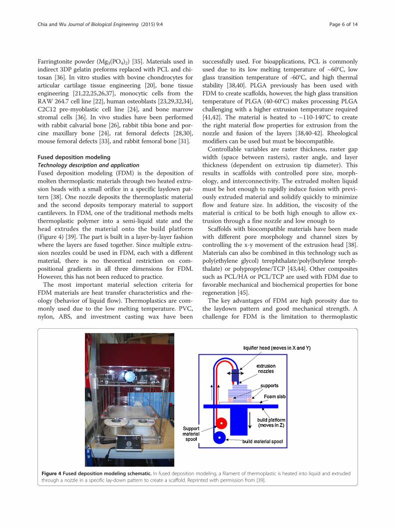
Fused deposition modelingTechnology description and applicationFused deposition modeling (FDM) is the deposition ofmolten thermoplastic materials through two heated extru-sion heads with a small orifice in a specific laydown pat-tern [38]. One nozzle deposits the thermoplastic materialand the second deposits temporary material to supportcantilevers. In FDM, one of the traditional methods meltsthermoplastic polymer into a semi-liquid state and thehead extrudes the material onto the build platform(Figure 4) [39]. The part is built in a layer-by-layer fashionwhere the layers are fused together. Since multiple extru-sion nozzles could be used in FDM, each with a differentmaterial, there is no theoretical restriction on com-positional gradients in all three dimensions for FDM.However, this has not been reduced to practice.The most important material selection criteria for
FDM materials are heat transfer characteristics and rhe-ology (behavior of liquid flow). Thermoplastics are com-monly used due to the low melting temperature. PVC,nylon, ABS, and investment casting wax have been
Figure 4 Fused deposition modeling schematic. In fused deposition mothrough a nozzle in a specific lay-down pattern to create a scaffold. Reprin
successfully used. For bioapplications, PCL is commonlyused due to its low melting temperature of ~60°C, lowglass transition temperature of -60°C, and high thermalstability [38,40]. PLGA previously has been used withFDM to create scaffolds, however, the high glass transitiontemperature of PLGA (40-60°C) makes processing PLGAchallenging with a higher extrusion temperature required[41,42]. The material is heated to ~110-140°C to createthe right material flow properties for extrusion from thenozzle and fusion of the layers [38,40-42]. Rheologicalmodifiers can be used but must be biocompatible.Controllable variables are raster thickness, raster gap
width (space between rasters), raster angle, and layerthickness (dependent on extrusion tip diameter). Thisresults in scaffolds with controlled pore size, morph-ology, and interconnectivity. The extruded molten liquidmust be hot enough to rapidly induce fusion with previ-ously extruded material and solidify quickly to minimizeflow and feature size. In addition, the viscosity of thematerial is critical to be both high enough to allow ex-trusion through a fine nozzle and low enough toScaffolds with biocompatible materials have been made
with different pore morphology and channel sizes bycontrolling the x-y movement of the extrusion head [38].Materials can also be combined in this technology such aspoly(ethylene glycol) terephthalate/poly(butylene tereph-thalate) or polypropylene/TCP [43,44]. Other compositessuch as PCL/HA or PCL/TCP are used with FDM due tofavorable mechanical and biochemical properties for boneregeneration [45].The key advantages of FDM are high porosity due to
the laydown pattern and good mechanical strength. Achallenge for FDM is the limitation to thermoplastic
deling, a filament of thermoplastic is heated into liquid and extrudedted with permission from [39].

Chia and Wu Journal of Biological Engineering (2015) 9:4 Page 7 of 14
materials with good melt viscosity properties which havehigh enough viscosity to build but low enough viscosityfor extrusion. Also, these properties have limited shapecomplexity for biological scaffolding materials and typic-ally result in relatively regular structures [40]. It shouldbe noted that geometric complexity is not limited forFDM using industrial materials which are selected tohave optimal thermal and rheological properties but lackbiocompatibility. Another disadvantage for FDM is theinability to incorporate living cells or temperature sensi-tive biological agents during extrusion due to the highprocessing temperature.
Recent material and technology advancesFDM has commonly used biocompatible polymers withlow melting temperatures. Materials used in FDM tocreate scaffolds are PCL and bioactive glass composites[46], L-lactide/e-caprolactone [46], PLGA with collageninfiltration [47], PCL-TCP with gentamicin [48], PCL-TCP [49], PLGA-TCP and coated with HA[42] , PCL-PLGA-TCP [50], PLGA-PCL [51], PCL coated withgelatin [52], PCL [53,54], PMMA [55], and PLA [46]. Invitro studies have been performed with porcine chon-drocytes [47], mouse pre-osteoblasts [52], and bonemarrow-derived mesenchymal stem cell [53]. In vivostudies with murine animal models for wound healing[48], human patient for craniofacial defect [49], andrabbit bone defect [42,50]. Applications include cartilagetissue engineering, antibiotic delivery system[48], osse-ous craniofacial defects in humans [49,55], and bone tis-sue engineering [13].While the number of FDM filaments are increasing
every month, the material choices pale in comparison tothe total number of theromoplastics that can be formedby conventional injection molding. One recent advancemay vastly increase the range of materials available for3D Printing, and transform it from a prototypingmethod to a viable manufacturing method is to incorp-orate precision injection molding into 3D Printing gan-try. This combination has significant potential because it
Figure 5 Stereolithography schematic. Stereolithography is the polymerlaser (left) or top-down setup with digital light projection (right). Reproduc
can process most thermoplastics that exist as conven-tional injection molding pellets, without pre-processinginto fine powders or traditional FDM filaments. It is es-sentially mould-free injection molding of final structures,making it feasible to fabricate one-of-a-kind, one patientat a time medical device [56].
StereolithographyTechnology description and applicationStereolithography (SLA) is the regarded as the first rapidprototyping process and was developed in the late 1980s[57]. The original SLA rasters a HeCd-laser beam tospatially control the polymerization of photocurableresin in 2D patterns [58]. After each layer is cured, theplatform with the cured structure attached then lowersin the bottom-up approach and another layer of uncuredliquid resin spreads over the top. The topmost layer isnow ready to be patterned. For the top-down approach,light is projected onto a transparent plate initially posi-tioned near the bottom of the vessel holding the liquidresin (Figure 5) [59]. After a layer is patterned throughthe transparent plate, the cured structure is detachedfrom the transparent plate. The cured structure is raisedto allow uncured liquid resin to fill the space betweenthe structure and transparent plate. The next layer isnow ready to be patterned. Since rastering a laser beamcan be slow, especially for large parts, the masked lamptechnique was developed to cure an entire layer of pho-topolymers at a time. After the structure is built, theunpolymerized liquid resin is removed by draining. Post-curing in a UV oven converts any unreacted groups andstrengthens the part [60].Kinetics of the curing reactions occurring during
polymerization is critical. This affects the curing timeand the thickness of the layer polymerized. The kineticscan be controlled by the power of the light source, thescanning speed and the chemistry and amount of themonomer and photointiators. In addition, UV absorberscan be added to the resin to control the depth ofpolymerization [61].
ization of photocurable resin by a bottom-up system with scanninged with permission [59].

Chia and Wu Journal of Biological Engineering (2015) 9:4 Page 8 of 14
Materials must have photocurable moieties for photo-crosslinking. Typical materials used in STL includeacrylics and epoxies. For tissue engineering applications,there are very few biodegradable and biocompatible bio-materials that are dimensionally stable during photopoly-merization. Photocrosslinkable poly(propylene fumarate)(PPF) [62] is commonly used in SLA and has been used tofabricate complex 3D scaffolds with controlled micro-structures for reconstruction of rabbit cranial defects [58].PPF requires a reactive diluent, such as diethyl fumarateor N-vinyl-2-pyrrolidone, to reduce the viscosity of theresin for proper processing conditions [63]. These diluentsintroduce significant amounts of a non-degradable com-ponent. Resins with and without bioceramic dispersionshave been processed by SLA.Medical applications of SLA include the fabrication of
anatomical models for pre-surgical planning, and indir-ect fabrication of medical devices by using the SLA pat-terns for molds (e.g. filling a SLA structure to use as anegative mold) [64,65] . Titanium dental implant com-ponents have been fabricated by electrical discharge ma-chining of titanium ingot based on a SLA model.The advantages of SLA are the ability to create com-
plex shapes with internal architecture, ease of removalof unpolymerized resin, and extremely high feature reso-lution (~1.2 um) [66]. The main disadvantage of SLA isthe scarcity of biocompatible resins with proper SLAprocessing properties. Additional challenges are the useof photointiators and radicals which may be cytotoxic(with long processing times), entrapment of unreactedmonomer and residual photoinitiator, and inability tocreate compositional gradients along horizontal planes.Photopolymerized resin also has poor mechanical prop-erties that are needed for hard tissue engineering. Lastly,temporary support structures must be incorporated intothe CAD model to fabricate unsupported features (e.g.overhangs, cantilevers). Complete removal of supportstructures may be difficult.
Recent material and technology advancesRecent improvements for SLA have been increasing thelibrary of photocrosslinkable polymers and the use ofmultiple resins for one build. Over the last few years,more polymers are synthesized containing aliphatic poly-esters which allow for biodegradation. The resultingmacromer is then acrylated to allow for photocrosslink-ing capability. The use of multiple resins for one buildwas shown with patterning PEG-DMA and PEG-DAwith fluorescently labeled dextran, fluorescently labeledbioactive PEG or bioactive PEG in different regions ofthe scaffold [67]. When changing material, the scaffoldwould be removed from the pool of resin, rinsed withdistilled water, and new resin added to the vat. A fixturewas used to maintain X-Y registration of the scaffold to
ensure alignment of layers. Dynamic mask projectionSLA has been able to achieve a lateral resolution of ∼ 2μm, and vertical resolution of ∼ 1 μm for PPF resin [68].The microstructures able to be produced with this tech-nology are extremely detailed although there are stillchallenges of creating horizontal channels and prevent-ing shrinkage of structures.SLA recently has increased the library of resins with
biodegradable moieties and the encapsulation of cellsduring processing. Novel macromers synthesized includesegments of PCL (three-armed hydroxyl-terminated)[69] or poly(D,L-lactide) [63,70,71]. Photo-curable poly(D,L-lactide) (PLLA) resin without the use of reactivediluents has been developed and applied in SLA [70].The end groups are modified to acrylate or methacrylateto allow for photo-crosslinking capability. Another resinrecently used in making SLA scaffolds is PPF-DEF [72,73]and PPF-DEF with BMP-2 loaded PLGA microspheres[74]. PPF-DEF or PPF-DEF with HA is used in μSL (<5μm resolution) although shrinkage of the polymer occursto cause warping of the parts [68,75]. Poly(trimethylenecarbonate) macromers have been used for flexible, elasticapplications with stiffness of 22-156 kPa [76] such as forcartilage tissue engineering [77]. Stiffer structures havebeen studied in vitro with mouse pre-osteoblasts [70], hu-man umbilical vein endothelial cells [78], rat bone marrowcells [73], MC3T3-E1 pre-osteoblasts [63,72,74], and hu-man mesenchymal stem cells[71]. A large application ofSLA is bone tissue engineering [79] and in vivo studieshave shown promoted bone formation in rat cranial de-fects [74]. For softer, flexible applications such as cartilagetissue engineering in vitro studies have been performedwith bovine chondrocytes [77]. Cell seeding and cul-turing was found to be improved with scaffolds withSLA-controlled pore network architecture compared toscaffolds made from salt leaching with poly(D,L-lactide)oligomers and PFF-DEF [73,80]. Cell encapsulation duringSLA has been shown with PEG-DA with NIH/3T3 cells[81] and PEG-DMA with human chondrocytes althoughwith an inkjet printer [82].
Selective laser sintering/meltingTechnology description and applicationSelective laser sintering (SLS) was develop by the Universityof Texas in 1989. SLS is similar to 3DP in binding togetherpowder particles in thin layers except a CO2 laser beam isused (Figure 6) [83]. The laser scans the surface of the pow-dered polymer particles in a specific 2D pattern to sinter byheating them above the glass transition temperature. Dur-ing sintering, molecular diffusion along the outermost sur-face of the particle lead to neck formation betweenneighboring particles. After one layer is created, the pistoncontaining the part is lowered and a fresh layer of powdermaterial is rolled across the top surface. The subsequent
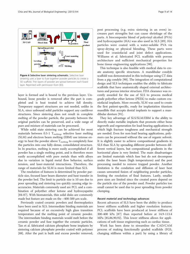
Figure 6 Selective laser sintering schematic. Selective lasersintering uses a laser to fuse together powder particles to create a3D scaffold. Thin layers of powder are spread between each fusedlayer. Reprinted with permission from [83].
Chia and Wu Journal of Biological Engineering (2015) 9:4 Page 9 of 14
layer is formed and is bound to the previous layer. Un-bound, loose powder is removed after the part is com-pleted and is heat treated to achieve full density.Temporary support structures are not needed, unlike inSLA, since unbound solid particles support any cantileverstructures. Since sintering does not result in completemelting of the powder particle, the porosity between theoriginal particles can be preserved, and a wide range ofpure and mixture of materials can be processed.While solid state sintering can be achieved for most
materials between 0.5-1 Tmelting, selective laser melting(SLM) and electron beam melting (EBM) use intense en-ergy to heat the powder above Tmelting to completely fusethe particles into one fully-dense, consolidated structure.In In practice, melting is more easily accomplished if allpowder has a single melting point, and is therefore moreeasily accomplished with pure metals than with alloysdue to variation in liquid metal flow behavior, surfacetension, and laser-material interactions. Therefore, therange of materials for SLM is more limited than SLS.The resolution of features is determined by powder par-
ticle size, focused laser beam diameter and heat transfer inthe powder bed. The limit to particle size is 10 um due topoor spreading and sintering too quickly causing edge in-accuracies. Materials commonly used are PCL and a com-bination of polyether ether ketone and hydroxyapatite[84-87]. With biomaterials, thin solid disks are commonlymade but feature are made on the ~400-500 μm scale.Previously coated ceramic powders and thermoplastics
have been used in SLS. Intermediate binding materials arerequired because of an excessively high glass transitiontemperature and the melting point of ceramic powder.The intermediate binding materials would melt before theceramic powder and fuse together the ceramic particles.Tan et al. fabricated calcium phosphate bone implants bysintering calcium phosphate powder coated with polymer[88]. After the part is built and excess powder removed,
post processing (e.g. extra sintering in an oven) in-creases part strengths but can cause shrinkage of theparts. A biocomposite blend of polyvinyl alcohol (PVA)and hydroxyapatite (HA) was also used in SLS [89]. HAparticles were coated with a water-soluble PVA viaspray-drying or physical blending. These parts wereused for craniofacial and joint defect applications.Williams et al. fabricated PCL scaffolds with porousarchitecture and sufficient mechanical properties forbone tissue engineering applications [90].This technique is also feasible with medical data to cre-
ate anatomy specific structures. A mandibular condylescaffold was demonstrated in this technique using CT datafrom a pig condyle [90]. The integration of computationaldesign and SLS techniques enables the ability to fabricatescaffolds that have anatomically shaped external architec-tures and porous interior structure. FDA clearance was re-cently awarded for the use of SLS to process medicalgrade polyether ether ketone (PEEK) to make custom cra-niofacial implants. More recently, SLM was used to createthe first patient-specific, ready for implantation titaniummandible that accepts dental implants to support a man-dibular denture [91].They key advantage of SLS/SLM/EBM is the ability to
directly make metallic implants that promote either boneingrowth and regeneration for load-bearing applications inwhich high fracture toughness and mechanical strengthare needed. Even for non-load bearing applications, poly-mers can be processed without the use of organic solvent.It is slightly easier to achieve compositional gradients inSLS than SLA by spreading different powder between dif-ferent vertical layers, but compositional gradients in thehorizontal plane is very limited. The main disadvantagesare limited materials which fuse but do not decomposeunder the laser beam (high temperatures) and the postprocessing needed to remove trapped powder. Anotherlimitation is the condution and diffusion of laser heatcauses unwanted fusion of neighboring powder particles,limiting the resolution of final features. Lastly, smallerpore sizes are limited since the created pores depend onthe particle size of the powder used. Powder particles toosmall cannot be used due to poor spreading from powderclumping.
Recent material and technology advancesRecent advances of SLS have been the ability to producelower stiffness scaffolds and higher resolution features.PCL scaffolds have been produced at lower stiffness of300-400 kPa [87] than reported before at 14.9-113.4MPa [85,86,90,92]. This lower stiffness allows for appli-cations of soft tissue engineering such as cardiac tissue.Work has been done to streamline the CAD/CAM
process of making functionally graded scaffolds (FGS,changing stiffness within a part) by using a library of

Figure 7 Bioprinting schematic. In bioprinting, small balls ofbioink composed of cells and hydrogel materials (e.g. alginate ordecellularized extracellular matrix) are printed in a desired shape.Reproduced with permission from [11].
Chia and Wu Journal of Biological Engineering (2015) 9:4 Page 10 of 14
polyhedrals to control the porosity. The porosity thenprocessed is related to the stiffness of the scaffold anddemonstrated with PCL in SLS [93]. A thorough reviewon the development of the design of microarchitecturecan be found [94]. In addition, FEA has been used tohelp design microarchitecture and predict mechanicalproperties for SLS [92,95].For SLS, common materials used are PCL and HA
[92,96,97], PCL and β-TCP with collagen coating [98],Ca-P/PHBV and CHAp/PLLA [99,100], and PVA [101].To demonstrate encapsulation of biomolecules, BSA wasencapsulated in Ca-P/PHBV microparticles and processed[102]. In vitro studies have been performed with C2C12myoblast cells for cardiac tissue engineering [87], SaOS-2cells [99], human bone marrow stromal cells [103], andhuman osteoprogenitor cells [52], porcine adipose-derivedstem cells [98,104], and MG-63 [101] for bone tissue en-gineering. In vivo studies have been performed in nudemice showed better woven bone and vascular tissue for-mation [98]. Applications are bone tissue engineering andinterbody cages for spinal fusions [97].
3D Plotting/Direct-write bioprintingTechnology description and application3D plotting was developed at the Freiburg MaterialsResearch Center in 2000 to create soft tissue scaffolds. 3Dplotting is based on extruding a viscous liquid material(generally a solution, paste, or dispersion) from a pressur-ized syringe into a liquid medium with matching density.The material is deposited in one long continuous strandor in individual dots from a nozzle or syringe to create adesired 3D shape of ceramics, polymers, or hydrogels[105]. The process can be at room temperature or at ele-vated temperatures, but does not involve thermoplasticsas in FDM.This SFF method is particularly applicable for natural
biomaterials to create hydrogels. Landers et al. used ther-moreversible natural polymers such as agar and gelatin insolution. The solution is heated and extruded at ~80°Cinto a cooler liquid medium (~20°C) of gelatin or siliconeoil to quickly solidify the heated solution. [106,107]. An-other approach is to extrude polymers into a liquidmedium containing reactants for crosslinking. An examplematerial is extruding gelatin into a Ca2+ reservoir for mi-crovasculature [108]. For other materials such as TCP, asolution is made with water, extruded from a syringe, andthen lyophilized to remove the liquid [109]. The resultingdiameter of each strut was ~400 μm.The key advantages are material flexibility and room
temperature processing (if applicable). In addition, manyof the other SFF technologies cannot use natural poly-mers due to processing conditions. One key disadvan-tage is the difficulty in fabricating complex shapes withoverhangs since a temporary, sacrificial material is
needed. In addition, hydrogels created in this methodhave low stiffness which may result in collapse of struc-tures or limitations on complexity of shapes.Similarly, bioprinting is the fabrication of hydrogel
structures with direct incorporation of cells (Figure 7).Cells are added during processing in cell printing strat-egies such as alginate-cell (bovine chondrocytes) solutionextruded from a syringe [110], electrostatically driven ink-jet printing of bovine vascular endothelial cells in culturemedium [111], laser-guided direct writing of embryonicchick spinal cord cells [112], and laser-induced forwardtransfer of cells suspended in alginate [113]. This technol-ogy provides a controlled spatial distribution of cell orgrowth factors as well as the scaffold structures. However,this fabrication technique is generally limited to hydrogelmaterials such as alginate and fibrin, which may not beideal for the implantation in biological environments thatrequire strong mechanical properties. Example applica-tions are rat smooth muscle cell-laden collagen droplets(650 μm diameter) to create specific cell spatial patterns in3D [114]. This SFF method is especially good for low vis-cosity materials and the buoyancy due to the densitymatching of the extruded material to the liquid mediumprevents collapse of the shape. The strand thickness canbe varied by material viscosity, deposition speed, extrusiontip diameter, and applied pressure.The key advantages of bioprinting are the room tem-
perature processing (if applicable), direct incorporationof cells, and homogenous distribution of cells. The keydisadvantages are limited mechanical stiffness, criticaltiming of gelation time, specific matching of materialand liquid medium densities to preserve shapes, and lowresolution. Further development of materials that areoptimal for biofactor printing, and next generation print-heads that can separately deposit multiple biofactors andmaterials onto the same platform, will provide the

Chia and Wu Journal of Biological Engineering (2015) 9:4 Page 11 of 14
potential to create constructs satisfying complex bio-logical requirements of tissue engineering scaffolds.
Recent material and technology advancesBioplotting materials include PLGA, TCP, collagen andchitosan [109], chitosan [115], collagen-alginate-silicacomposites coated with HA [116], soy protein [117,118],and agarose with gelatin [107]. In vitro studies have beenperformed with mouse pre-osteoblasts [116] and humanmesenchymal stem cells [117]. In vivo studies have beenperformed in ovine cavalarial defects [109]. Applicationsinclude bone tissue engineering [109,116], tissue regen-eration [118].Bioprinting materials are agarose with human umbil-
ical vein smooth muscle cells (HUVSMCs) and humanskin fibroblasts (rods) [119], gelatin-HA-tetraPEG-DAwith NIH 3T3s (rods) [120], rat primary bladder smoothmuscle cells in collagen droplets [114], human micro-vascular endothelial cells in fibrin (inkjet printer) [121],and alginate droplets [108]. Applications are mainly forvascular tissue engineering [108,119-121].Recent studies show the ability to bioprint single cells
and cell-laden hydrogel-PCL scaffolds. High throughputprinting of single-cell arrays has been shown with“Block-Cell-Printing” [122]. Microfluidic arrays of hook-shaped traps are used to trap single cells. Trapped cellscan be paired and separated 5 μm to study cell com-munication. In this study, trapped primary rat corticalneurons were cultured and cells exhibited neuronalmorphology. Ahn et al. bioprinted high density cell-laden hydrogels by extruding a 4°C cell-alginate solutiononto a -10°C stage to create a structure [123]. The algin-ate was crosslinked to provide strength by incubatingthe structure in a CaCl2 solution. Good cell viability ofwas shown for human mesenchymal stem cells andhuman osteoblast-like cells after processing. Lastly, a layer-by-layer process has alternately deposited chondrocyte-laden hydrogel droplets (alginate or decellularizedextracellular matrix bioink) and PCL in a layer-by-layerprocess to create a 3D structure [124-126] (Figure 7).Recent advances in biofactor printing technology allow
the simultaneous printing of pharmaceutical and bio-logical agents during fabrication. Xu et al. demonstratedthat inkjet printing technology can precisely place thecells and proteins into 3D alginate structures [127].
Future directionAdditional progress for 3D Printing technologies isneeded for increasing resolution without sacrificingshape, strength, and handability of scaffolds. Anatom-ical features and tissue architecture may have details onthe scale of hundreds of microns (e.g. villi of the smallintestine with ~500 um diameters). Diffusion consump-tion modeling has shown a 200 μm limit in scaffolds
for oxygen transport to cells, resulting in a maximum of400 μm diameter features for cell survival [128]. For bothSLS and 3DP, there is a challenge with creating strongerstructures without increasing dimensions. To create smallfeatures which survives the fabrication process, powderparticles much be bound together tightly. By increasingthe strength of the laser for SLS or amount of binder for3DP, additional powder particles would bind and thereforeincrease the dimensions. Additional work is needed tomove SLS and 3DP to resolutions below 400-500 μm. Inaddition, unbound trapped powder is difficult to removefrom small channels. Future work is needed to create pow-der that is easily removable with traditional methods ofhigh-pressured air. One strategy is to create sphericalpowder particles which would facilitate removal in tightspaces.While SLA can reach extremely high resolutions, there
are a limited number of biodegradable, biocompatibleresins. Advances have been made to synthesize newmacromers with biodegradable moieties, however, thesematerials have not been FDA approved. FDM, SLS, and3DP are able to use polymers such as PLGA, PLLA, andPCL without chemical modification which will help ex-pedite future FDA approval for biomedical devices.Although macro and microarchitecture has made great
strides in the past five years, additional work shouldfocus on the nanoarchitecture (e.g. biochemical mole-cules). Due to harsh processing conditions of SFFmethods (e.g. heat, organic solvent), biochemical mole-cules are not generally incorporated directly into thescaffold. While biochemical molecules can be coatedonto structures in post-processing, there is a need forsustained growth factor release over time. Therefore,strategies to incorporate biochemical molecules directlyinto scaffolds for prolonged release will be needed.Although the focus of this review article is on the fabri-
cation techniques and biomaterials used in 3DP, the deg-radation kinetics and byproducts of the materials are infact a very significant problem in 3D scaffolds due to masstransport limitations within thick scaffolds. This is a mov-ing boundary diffusion-reaction problem that even with-out biodegradable biomaterials can result in hypoxia andacidosis within the scaffolds. The release of acidic degrad-ation products is expected to worsen the acidosis whichmay harm the seeded cells and/or the surrounding cells”.
Competing interestsThe authors declare that they have no competing interests.
Authors’ contributionsHNC and BMW conceived, wrote, and edited the manuscript. Both authorshave read and approved the final manuscript.
Author details1Department of Bioengineering, Henry Samueli School of Engineering,University of California, 5121 Engineering V, Los Angeles, CA 90095, USA.2Department of Materials Science and Engineering, Henry Samueli School of

Chia and Wu Journal of Biological Engineering (2015) 9:4 Page 12 of 14
Engineering, University of California, Los Angeles, CA 90095, USA. 3Division ofAdvanced Prosthodontics, School of Dentistry, University of California, LosAngeles, CA 90095, USA. 4Department of Orthopedic Surgery, School ofMedicine, University of California, Los Angeles, CA 90095, USA.
Received: 9 September 2014 Accepted: 17 January 2015
References1. Karande TS, Ong JL, Agrawal CM. Diffusion in musculoskeletal tissue
engineering scaffolds: design issues related to porosity, permeability,architecture, and nutrient mixing. Ann Biomed Eng. 2004;32:1728–43.
2. Hollister SJ. Porous scaffold design for tissue engineering. Nat Mater.2005;4:518–24.
3. Stevens MM, George JH. Exploring and engineering the cell surfaceinterface. Science. 2005;310:1135–8.
4. Winder J, Bibb R. Medical rapid prototyping technologies: state of the artand current limitations for application in oral and maxillofacial surgery.J Oral Maxillofac Surg. 2005;63:1006–15.
5. Colin A, Boire J-Y. A novel tool for rapid prototyping and development ofsimple 3D medical image processing applications on PCs. Comput MethodsPrograms Biomed. 1997;53:87–92.
6. Winder J. Medical rapid prototyping and 3D CT in the manufacture ofcustom made cranial titanium plates. J Med Eng Technol. 1999;23:26–8.
7. Hollister S, Maddox R, Taboas J. Optimal design and fabrication of scaffoldsto mimic tissue properties and satisfy biological constraints. Biomaterials.2002;23:4095–103.
8. Cima MJ, Sachs E, Cima LG, Yoo J, Khanuja S, Borland SW, et al. Computer-derived microstructures by 3D printing: bio-and structural materials. SolidFreeform Fabr Symp Proc: DTIC Document; 1994. p. 181-90
9. Griffith LG, Wu B, Cima MJ, Powers MJ, Chaignaud B, Vacanti JP. In VitroOrganogenesis of Liver Tissuea. Ann N Y Acad Sci. 1997;831:382–97.
10. Wu BM, Borland SW, Giordano RA, Cima LG, Sachs EM, Cima MJ. Solid free-formfabrication of drug delivery devices. J Control Release. 1996;40:77–87.
11. Billiet T, Vandenhaute M, Schelfhout J, Van Vlierberghe S, Dubruel P. Areview of trends and limitations in hydrogel-rapid prototyping for tissueengineering. Biomaterials. 2012;33:6020–41.
12. Wu BM, Cima MJ. Effects of solvent‐particle interaction kinetics onmicrostructure formation during three‐dimensional printing. Polymer EngSci. 1999;39:249–60.
13. Kim SS, Utsunomiya H, Koski JA, Wu BM, Cima MJ, Sohn J, et al. Survival andfunction of hepatocytes on a novel three-dimensional synthetic biodegradablepolymer scaffold with an intrinsic network of channels. Ann Surg. 1998;228:8.
14. Lam CXF, Mo XM, Teoh SH, Hutmacher DW. Scaffold development using 3Dprinting with a starch-based polymer. Mater Sci Eng C. 2002;20:49–56.
15. Zeltinger J, Sherwood JK, Graham DA, Müeller R, Griffith LG. Effect of poresize and void fraction on cellular adhesion, proliferation, and matrixdeposition. Tissue Eng. 2001;7:557–72.
16. Seitz H, Rieder W, Irsen S, Leukers B, Tille C. Three‐dimensional printing ofporous ceramic scaffolds for bone tissue engineering. J Biomed Mater Res BAppl Biomater. 2005;74:782–8.
17. Lee M, Dunn JCY, Wu BM. Scaffold fabrication by indirect three-dimensionalprinting. Biomaterials. 2005;26:4281–9.
18. Lee M, Wu BM, Dunn JCY. Effect of scaffold architecture and pore size onsmooth muscle cell growth. J Biomed Mater Res A. 2008;87:1010–6.
19. Sherwood JK, Riley SL, Palazzolo R, Brown SC, Monkhouse DC, Coates M,et al. A three-dimensional osteochondral composite scaffold for articularcartilage repair. Biomaterials. 2002;23:4739–51.
20. Shanjani Y, Croos D, Amritha J, Pilliar RM, Kandel RA, Toyserkani E. Solidfreeform fabrication and characterization of porous calcium polyphosphatestructures for tissue engineering purposes. J Biomed Mater Res B ApplBiomater. 2010;93:510–9.
21. Seitz H, Deisinger U, Leukers B, Detsch R, Ziegler G. Different CalciumPhosphate Granules for 3‐D Printing of Bone Tissue Engineering Scaffolds.Adv Eng Mater. 2009;11:B41–B6.
22. Detsch R, Schaefer S, Deisinger U, Ziegler G, Seitz H, Leukers B. In vitro-osteoclastic activity studies on surfaces of 3D printed calcium phosphatescaffolds. J Biomater Appl. 2010.
23. Warnke PH, Seitz H, Warnke F, Becker ST, Sivananthan S, Sherry E, et al.Ceramic scaffolds produced by computer‐assisted 3D printing and sintering:
Characterization and biocompatibility investigations. J Biomed Mater Res BAppl Biomater. 2010;93:212–7.
24. Abarrategi A, Moreno-Vicente C, Martínez-Vázquez FJ, Civantos A, Ramos V,Sanz-Casado JV, et al. Biological properties of solid free form designed ceramicscaffolds with BMP-2: in vitro and in vivo evaluation. PLoS One. 2012;7:e34117.
25. Becker ST, Bolte H, Krapf O, Seitz H, Douglas T, Sivananthan S, et al.Endocultivation: 3D printed customized porous scaffolds for heterotopicbone induction. Oral Oncol. 2009;45:e181–e8.
26. Tamimi F, Torres J, Gbureck U, Lopez-Cabarcos E, Bassett DC, Alkhraisat MH,et al. Craniofacial vertical bone augmentation: a comparison between 3Dprinted monolithic monetite blocks and autologous onlay grafts in therabbit. Biomaterials. 2009;30:6318–26.
27. Butscher A, Bohner M, Roth C, Ernstberger A, Heuberger R, Doebelin N,et al. Printability of calcium phosphate powders for three-dimensionalprinting of tissue engineering scaffolds. Acta Biomater. 2012;8:373–85.
28. Tarafder S, Balla VK, Davies NM, Bandyopadhyay A, Bose S. Microwave‐sintered 3D printed tricalcium phosphate scaffolds for bone tissueengineering. J Tissue Eng Regen Med. 2013;7:631–41.
29. Santos CF, Silva AP, Lopes L, Pires I, Correia IJ. Design and production ofsintered β-tricalcium phosphate 3D scaffolds for bone tissue regeneration.Mater Sci Eng C. 2012;32:1293–8.
30. Tarafder S, Davies NM, Bandyopadhyay A, Bose S. 3D printed tricalciumphosphate bone tissue engineering scaffolds: effect of SrO and MgOdoping on in vivo osteogenesis in a rat distal femoral defect model.Biomater Sci. 2013;1:1250–9.
31. Tarafder S, Dernell WS, Bandyopadhyay A, Bose S. SrO‐and MgO‐dopedmicrowave sintered 3D printed tricalcium phosphate scaffolds: Mechanicalproperties and in vivo osteogenesis in a rabbit model. J Biomed Mater ResPart B: Appl Biomat. 2014
32. Suwanprateeb J, Sanngam R, Suvannapruk W, Panyathanmaporn T.Mechanical and in vitro performance of apatite–wollastonite glass ceramicreinforced hydroxyapatite composite fabricated by 3D-printing. J Mater SciMater Med. 2009;20:1281–9.
33. Inzana JA, Olvera D, Fuller SM, Kelly JP, Graeve OA, Schwarz EM, et al. 3Dprinting of composite calcium phosphate and collagen scaffolds for boneregeneration. Biomaterials. 2014;35:4026–34.
34. Ge Z, Wang L, Heng BC, Tian X-F, Lu K, Fan VTW, et al. Proliferation anddifferentiation of human osteoblasts within 3D printed poly-lactic-co-gly-colic acid scaffolds. J Biomater Appl. 2009;23:533–47.
35. Klammert U, Vorndran E, Reuther T, Müller FA, Zorn K, Gbureck U. Lowtemperature fabrication of magnesium phosphate cement scaffolds by 3Dpowder printing. J Mater Sci Mater Med. 2010;21:2947–53.
36. Lee J-Y, Choi B, Wu B, Lee M. Customized biomimetic scaffolds created byindirect three-dimensional printing for tissue engineering. Biofabrication.2013;5:045003.
37. Bose S, Vahabzadeh S, Bandyopadhyay A. Bone tissue engineering using 3Dprinting. Mater Today. 2013;16:496–504.
38. Zein I, Hutmacher DW, Tan KC, Teoh SH. Fused deposition modeling ofnovel scaffold architectures for tissue engineering applications. Biomaterials.2002;23:1169–85.
39. van Noort R. The future of dental devices is digital. Dent Mater. 2012;28:3–12.40. Hutmacher DW, Schantz T, Zein I, Ng KW, Teoh SH, Tan KC. Mechanical
properties and cell cultural response of polycaprolactone scaffolds designedand fabricated via fused deposition modeling. J Biomed Mater Res.2001;55:203–16.
41. Park SH, Park DS, Shin JW, Kang YG, Kim HK, Yoon TR, et al. Scaffolds forbone tissue engineering fabricated from two different materials by therapid prototyping technique: PCL versus PLGA. J Mater Sci Mater Med.2012;23:2671–8.
42. Kim J, McBride S, Tellis B, Alvarez-Urena P, Song Y-H, Dean DD, et al.Rapid-prototyped PLGA/β-TCP/hydroxyapatite nanocomposite scaffolds in arabbit femoral defect model. Biofabrication. 2012;4:025003.
43. Woodfield TB, Malda J, De Wijn J, Peters F, Riesle J, van Blitterswijk CA.Design of porous scaffolds for cartilage tissue engineering using a three-dimensional fiber-deposition technique. Biomaterials. 2004;25:4149–61.
44. Kalita SJ, Bose S, Hosick HL, Bandyopadhyay A. Development of controlledporosity polymer-ceramic composite scaffolds via fused depositionmodeling. Mater Sci Eng C. 2003;23:611–20.
45. Rai B, Teoh SH, Ho KH, Hutmacher DW, Cao T, Chen F, et al. The effect ofrhBMP-2 on canine osteoblasts seeded onto 3D bioactive polycaprolactonescaffolds. Biomaterials. 2004;25:5499–506.

Chia and Wu Journal of Biological Engineering (2015) 9:4 Page 13 of 14
46. Korpela J, Kokkari A, Korhonen H, Malin M, Närhi T, Seppälä J. Biodegradableand bioactive porous scaffold structures prepared using fused depositionmodeling. J Biomed Mater Res B Appl Biomater. 2013;101:610–9.
47. Yen H-J, Tseng C-S, S-h H, Tsai C-L. Evaluation of chondrocyte growth in thehighly porous scaffolds made by fused deposition manufacturing (FDM)filled with type II collagen. Biomed Microdevices. 2009;11:615–24.
48. Teo EY, Ong S-Y, Khoon Chong MS, Zhang Z, Lu J, Moochhala S, et al.Polycaprolactone-based fused deposition modeled mesh for delivery ofantibacterial agents to infected wounds. Biomaterials. 2011;32:279–87.
49. Probst F, Hutmacher D, Müller D, Machens H, Schantz J. Calvarial reconstructionby customized bioactive implant. Handchir Mikrochir Plast Chir. 2010;42:369–73.
50. Shim J-H, Moon T-S, Yun M-J, Jeon Y-C, Jeong C-M, Cho D-W, et al. Stimulationof healing within a rabbit calvarial defect by a PCL/PLGA scaffold blended withTCP using solid freeform fabrication technology. J Mater Sci Mater Med.2012;23:2993–3002.
51. Kim JY, Cho D-W. Blended PCL/PLGA scaffold fabrication using multi-headdeposition system. Microelectron Eng. 2009;86:1447–50.
52. Van Bael S, Desmet T, Chai YC, Pyka G, Dubruel P, Kruth J-P, et al. In vitrocell-biological performance and structural characterization of selective lasersintered and plasma surface functionalized polycaprolactone scaffolds forbone regeneration. Mater Sci Eng C. 2013;33:3404–12.
53. Kang S-W, Bae J-H, Park S-A, Kim W-D, Park M-S, Ko Y-J, et al. Combinationtherapy with BMP-2 and BMSCs enhances bone healing efficacy of PCLscaffold fabricated using the 3D plotting system in a large segmental defectmodel. Biotechnol Lett. 2012;34:1375–84.
54. Shim J-H, Lee J-S, Kim JY, Cho D-W. Bioprinting of a mechanically enhancedthree-dimensional dual cell-laden construct for osteochondral tissueengineering using a multi-head tissue/organ building system. J MicromechMicroeng. 2012;22:085014.
55. Espalin D, Arcaute K, Rodriguez D, Medina F, Posner M, Wicker R. Fuseddeposition modeling of patient-specific polymethylmethacrylate implants.Rapid Prototyping J. 2010;16:164–73.
56. Arburg. 3D printing with freeform from ARBURG.57. Dowler C. Automatic model building cuts design time, costs. Plastics Eng.
1989;45:43–5.58. Fisher JP, Dean D, Mikos AG. Photocrosslinking characteristics and
mechanical properties of diethyl fumarate/poly (propylene fumarate)biomaterials. Biomaterials. 2002;23:4333–43.
59. Melchels FP, Feijen J, Grijpma DW. A review on stereolithography and itsapplications in biomedical engineering. Biomaterials. 2010;31:6121–30.
60. Wang WL, Cheah CM, Fuh JYH, Lu L. Influence of process parameters onstereolithography part shrinkage. Mater Design. 1996;17:205–13.
61. Heller C, Schwentenwein M, Russmueller G, Varga F, Stampfl J, Liska R. Vinylesters: low cytotoxicity monomers for the fabrication of biocompatible 3Dscaffolds by lithography based additive manufacturing. J Polym Sci A PolymChem. 2009;47:6941–54.
62. Lee K-W, Wang S, Fox BC, Ritman EL, Yaszemski MJ, Lu L. Poly (propylenefumarate) bone tissue engineering scaffold fabrication using stereolithography:effects of resin formulations and laser parameters. Biomacromolecules.2007;8:1077–84.
63. Jansen J, Melchels FP, Grijpma DW, Feijen J. Fumaric acid monoethylester-functionalized poly (d, l-lactide)/N-vinyl-2-pyrrolidone resins for thepreparation of tissue engineering scaffolds by stereolithography.Biomacromolecules. 2008;10:214–20.
64. Kang H-W, Cho D-W. Development of an Indirect StereolithographyTechnology for Scaffold Fabrication with a wide range of biomaterialselectivity. Tissue Eng Part C Methods. 2012;18:719–29.
65. Park JH, Jung JW, Kang H-W, Cho D-W. Indirect three-dimensional printingof synthetic polymer scaffold based on thermal molding process.Biofabrication. 2014;6:025003.
66. Zhang X, Jiang X, Sun C. Micro-stereolithography of polymeric and ceramicmicrostructures. Sens Actuators A: Phys. 1999;77:149–56.
67. Arcaute K, Mann B, Wicker R. Stereolithography of spatially controlledmulti-material bioactive poly (ethylene glycol) scaffolds. Acta Biomater.2010;6:1047–54.
68. Choi J-W, Wicker R, Lee S-H, Choi K-H, Ha C-S, Chung I. Fabrication of 3Dbiocompatible/biodegradable micro-scaffolds using dynamic mask projectionmicrostereolithography. J Mater Process Technol. 2009;209:5494–503.
69. Elomaa L, Teixeira S, Hakala R, Korhonen H, Grijpma DW, Seppälä JV.Preparation of poly (ε-caprolactone)-based tissue engineering scaffolds bystereolithography. Acta Biomater. 2011;7:3850–6.
70. Melchels FP, Feijen J, Grijpma DW. A poly (D, L-lactide) resin for thepreparation of tissue engineering scaffolds by stereolithography.Biomaterials. 2009;30:3801–9.
71. Seck TM, Melchels FP, Feijen J, Grijpma DW. Designed biodegradablehydrogel structures prepared by stereolithography using poly (ethyleneglycol)/poly (d, l-lactide)-based resins. J Control Release. 2010;148:34–41.
72. Shin JH, Lee JW, Jung JH, Cho D-W, Lim G. Evaluation of cell proliferationand differentiation on a poly (propylene fumarate) 3D scaffold treated withfunctional peptides. J Mater Sci. 2011;46:5282–7.
73. Kim K, Dean D, Wallace J, Breithaupt R, Mikos AG, Fisher JP. The influence ofstereolithographic scaffold architecture and composition on osteogenicsignal expression with rat bone marrow stromal cells. Biomaterials.2011;32:3750–63.
74. Lee JW, Kang KS, Lee SH, Kim J-Y, Lee B-K, Cho D-W. Bone regeneration using amicrostereolithography-produced customized poly (propylene fumarate)/diethyl fumarate photopolymer 3D scaffold incorporating BMP-2 loadedPLGA microspheres. Biomaterials. 2011;32:744–52.
75. Lee JW, Ahn G, Kim DS, Cho D-W. Development of nano-and microscalecomposite 3D scaffolds using PPF/DEF-HA and micro-stereolithography.Microelectron Eng. 2009;86:1465–7.
76. Schüller‐Ravoo S, Feijen J, Grijpma DW. Preparation of flexible and elasticpoly (trimethylene carbonate) structures by stereolithography. MacromolBiosci. 2011;11:1662–71.
77. Schüller‐Ravoo S, Teixeira SM, Feijen J, Grijpma DW, Poot AA. Flexible andElastic Scaffolds for Cartilage Tissue Engineering Prepared byStereolithography Using Poly (trimethylene carbonate)‐Based Resins.Macromol Biosci. 2013;13:1711–9.
78. Gauvin R, Chen Y-C, Lee JW, Soman P, Zorlutuna P, Nichol JW, et al.Microfabrication of complex porous tissue engineering scaffolds using 3Dprojection stereolithography. Biomaterials. 2012;33:3824–34.
79. Kim K, Yeatts A, Dean D, Fisher JP. Stereolithographic bone scaffold designparameters: osteogenic differentiation and signal expression. Tissue EngPart B Rev. 2010;16:523–39.
80. Melchels FP, Barradas A, Van Blitterswijk CA, De Boer J, Feijen J, Grijpma DW.Effects of the architecture of tissue engineering scaffolds on cell seedingand culturing. Acta Biomater. 2010;6:4208–17.
81. Chan V, Zorlutuna P, Jeong JH, Kong H, Bashir R. Three-dimensionalphotopatterning of hydrogels using stereolithography for long-term cellencapsulation. Lab Chip. 2010;10:2062–70.
82. Cui X, Breitenkamp K, Finn M, Lotz M, D'Lima DD. Direct human cartilagerepair using three-dimensional bioprinting technology. Tissue Eng Part A.2012;18:1304–12.
83. Pattanayak DK, Fukuda A, Matsushita T, Takemoto M, Fujibayashi S, Sasaki K,et al. Bioactive Ti metal analogous to human cancellous bone: fabricationby selective laser melting and chemical treatments. Acta Biomater.2011;7:1398–406.
84. Lohfeld S, Tyndyk M, Cahill S, Flaherty N, Barron V, McHugh P. A method tofabricate small features on scaffolds for tissue engineering via selective lasersintering. J Biomed Sci Eng. 2010;3:138–47.
85. Wiria FE, Leong KF, Chua CK, Liu Y. Poly- < i > ε</i > -caprolactone/hydroxyapatitefor tissue engineering scaffold fabrication via selective laser sintering. ActaBiomater. 2007;3:1–12.
86. Tan K, Chua C, Leong K, Cheah C, Cheang P, Abu Bakar M, et al. Scaffolddevelopment using selective laser sintering of polyetheretherketone–hydroxyapatite biocomposite blends. Biomaterials. 2003;24:3115–23.
87. Yeong W, Sudarmadji N, Yu H, Chua C, Leong K, Venkatraman S, et al.Porous polycaprolactone scaffold for cardiac tissue engineering fabricatedby selective laser sintering. Acta Biomater. 2010;6:2028–34.
88. Tan KH, Chua CK, Leong KF, Cheah CM, Gui WS, Tan WS, et al. Selectivelaser sintering of biocompatible polymers for applications in tissueengineering. Bio-Med Mater Eng. 2005;15:113–24.
89. Chua C, Leong K, Tan K, Wiria F, Cheah C. Development of tissue scaffoldsusing selective laser sintering of polyvinyl alcohol/hydroxyapatite biocompositefor craniofacial and joint defects. J Mater Sci Mater Med. 2004;15:1113–21.
90. Williams JM, Adewunmi A, Schek RM, Flanagan CL, Krebsbach PH,Feinberg SE, et al. Bone tissue engineering using polycaprolactone scaffoldsfabricated via selective laser sintering. Biomaterials. 2005;26:4817–27.
91. Nickels L. World's first patient-specific jaw implant. Metal Powder Report.2012;67:12–4.
92. Eshraghi S, Das S. Mechanical and microstructural properties ofpolycaprolactone scaffolds with one-dimensional, two-dimensional, and

Chia and Wu Journal of Biological Engineering (2015) 9:4 Page 14 of 14
three-dimensional orthogonally oriented porous architectures produced byselective laser sintering. Acta Biomater. 2010;6:2467–76.
93. Sudarmadji N, Tan J, Leong K, Chua C, Loh Y. Investigation of themechanical properties and porosity relationships in selective laser-sinteredpolyhedral for functionally graded scaffolds. Acta Biomater. 2011;7:530–7.
94. Giannitelli S, Accoto D, Trombetta M, Rainer A. Current trends in the designof scaffolds for computer-aided tissue engineering. Acta Biomater.2014;10:580–94.
95. Eshraghi S, Das S. Micromechanical finite-element modeling and experimentalcharacterization of the compressive mechanical properties of polycaprolactone–hydroxyapatite composite scaffolds prepared by selective laser sintering forbone tissue engineering. Acta Biomater. 2012;8:3138–43.
96. Eosoly S, Brabazon D, Lohfeld S, Looney L. Selective laser sintering ofhydroxyapatite/poly-ε-caprolactone scaffolds. Acta Biomater. 2010;6:2511–7.
97. Kang H, Hollister SJ, La Marca F, Park P, Lin C-Y. Porous BiodegradableLumbar Interbody Fusion Cage Design and Fabrication Using IntegratedGlobal-Local Topology Optimization With Laser Sintering. J Biomech Eng.2013;135:101013.
98. Liao HT, Lee MY, Tsai WW, Wang HC, Lu WC. Osteogenesis of adipose‐derived stem cells on polycaprolactone–β‐tricalcium phosphate scaffoldfabricated via selective laser sintering and surface coating with collagentype I. J Tissue Eng Regenerative Med. 2013.
99. Duan B, Wang M, Zhou WY, Cheung WL, Li ZY, Lu WW. Three-dimensionalnanocomposite scaffolds fabricated via selective laser sintering for bonetissue engineering. Acta Biomater. 2010;6:4495–505.
100. Duan B, Wang M. Customized Ca–P/PHBV nanocomposite scaffolds forbone tissue engineering: design, fabrication, surface modification andsustained release of growth factor. J R Soc Interface. 2010;7:S615–S29.
101. Shuai C, Mao Z, Lu H, Nie Y, Hu H, Peng S. Fabrication of porous polyvinylalcohol scaffold for bone tissue engineering via selective laser sintering.Biofabrication. 2013;5:015014.
102. Duan B, Wang M. Encapsulation and release of biomolecules from Ca–P/PHBV nanocomposite microspheres and three-dimensional scaffoldsfabricated by selective laser sintering. Polym Degrad Stab. 2010;95:1655–64.
103. Xia Y, Zhou P, Cheng X, Xie Y, Liang C, Li C, et al. Selective laser sinteringfabrication of nano-hydroxyapatite/poly-ε-caprolactone scaffolds for bonetissue engineering applications. Int J Nanomedicine. 2013;8:4197.
104. C-j S, Z-z M, Z-k H, S-p P. Preparation of complex porous scaffolds viaselective laser sintering of poly (vinyl alcohol)/calcium silicate. Journal ofBioactive and Compatible Polymers: Biomedical Applications. 2014;29:110–20.
105. Landers R, Mülhaupt R. Desktop manufacturing of complex objects,prototypes and biomedical scaffolds by means of computer‐assisted designcombined with computer‐guided 3D plotting of polymers and reactiveoligomers. Macromol Mater Eng. 2000;282:17–21.
106. Landers R, Hübner U, Schmelzeisen R, Mülhaupt R. Rapid prototyping ofscaffolds derived from thermoreversible hydrogels and tailored forapplications in tissue engineering. Biomaterials. 2002;23:4437–47.
107. Maher P, Keatch R, Donnelly K, Paxton J. Formed 3D bio-scaffolds via rapidprototyping technology. 4th European Conference of the InternationalFederation for Medical and Biological Engineering: Springer; 2009. p. 2200-4.
108. Pataky K, Braschler T, Negro A, Renaud P, Lutolf MP, Brugger J. MicrodropPrinting of Hydrogel Bioinks into 3D Tissue‐Like Geometries. Adv Mater.2012;24:391–6.
109. Haberstroh K, Ritter K, Kuschnierz J, Bormann KH, Kaps C, Carvalho C, et al.Bone repair by cell‐seeded 3D‐bioplotted composite scaffolds made ofcollagen treated tricalciumphosphate or tricalciumphosphate‐chitosan‐collagen hydrogel or PLGA in ovine critical‐sized calvarial defects. J BiomedMater Res B Appl Biomater. 2010;93:520–30.
110. Cohen DL, Malone E, Lipson H, Bonassar LJ. Direct freeform fabrication ofseeded hydrogels in arbitrary geometries. Tissue Eng. 2006;12:1325–35.
111. Nakamura M, Kobayashi A, Takagi F, Watanabe A, Hiruma Y, Ohuchi K, et al.Biocompatible inkjet printing technique for designed seeding of individualliving cells. Tissue Eng. 2005;11:1658–66.
112. Odde DJ, Renn MJ. Laser‐guided direct writing of living cells. BiotechnolBioeng. 2000;67:312–8.
113. Koch L, Kuhn S, Sorg H, Gruene M, Schlie S, Gaebel R, et al. Laser printing ofskin cells and human stem cells. Tissue Eng Part C Methods. 2009;16:847–54.
114. Moon S, Hasan SK, Song YS, Xu F, Keles HO, Manzur F, et al. Layer by layerthree-dimensional tissue epitaxy by cell-laden hydrogel droplets. Tissue EngPart C Methods. 2009;16:157–66.
115. Lim TC, Chian KS, Leong KF. Cryogenic prototyping of chitosan scaffoldswith controlled micro and macro architecture and their effect on in vivoneo‐vascularization and cellular infiltration. J Biomed Mater Res A.2010;94:1303–11.
116. Lee H, Kim Y, Kim S, Kim G. Mineralized biomimetic collagen/alginate/silicacomposite scaffolds fabricated by a low-temperature bio-plotting processfor hard tissue regeneration: fabrication, characterisation and in vitro cellularactivities. J Mater Chem B. 2014.
117. Chien KB, Makridakis E, Shah RN. Three-dimensional printing of soy proteinscaffolds for tissue regeneration. Tissue Eng Part C Methods. 2012;19:417–26.
118. Chien KB, Aguado BA, Bryce PJ, Shah RN. In vivo acute and humoralresponse to three-dimensional porous soy protein scaffolds. Acta Biomater.2013;9:8983–90.
119. Norotte C, Marga FS, Niklason LE, Forgacs G. Scaffold-free vascular tissueengineering using bioprinting. Biomaterials. 2009;30:5910–7.
120. Skardal A, Zhang J, Prestwich GD. Bioprinting vessel-like constructs usinghyaluronan hydrogels crosslinked with tetrahedral polyethylene glycoltetracrylates. Biomaterials. 2010;31:6173–81.
121. Cui X, Boland T. Human microvasculature fabrication using thermal inkjetprinting technology. Biomaterials. 2009;30:6221–7.
122. Zhang K, Chou C-K, Xia X, Hung M-C, Qin L. Block-Cell-Printing for livesingle-cell printing. Proceedings of the National Academy of Sciences.2014:201313661
123. Ahn S, Lee H, Lee EJ, Kim G. A direct cell printing supplemented withlow-temperature processing method for obtaining highly porous three-dimensional cell-laden scaffolds. J Mater Chem B. 2014;2:2773–82.
124. Kundu J, Shim JH, Jang J, Kim SW, Cho DW. An additive manufacturing‐based PCL–alginate–chondrocyte bioprinted scaffold for cartilage tissueengineering. J Tissue Eng Regenerative Med. 2013.
125. Lee J-S, Hong JM, Jung JW, Shim J-H, Oh J-H, Cho D-W. 3D printing ofcomposite tissue with complex shape applied to ear regeneration.Biofabrication. 2014;6:024103.
126. Pati F, Jang J, Ha D-H, Kim SW, Rhie J-W, Shim J-H, et al. Printing three-dimensional tissue analogues with decellularized extracellular matrix bioink.Nat Commun. 2014;5
127. Xu T, Jin J, Gregory C, Hickman JJ, Boland T. Inkjet printing of viablemammalian cells. Biomaterials. 2005;26:93–9.
128. Dunn JCY, Chan WY, Cristini V, Kim JS, Lowengrub J, Singh S, et al. Analysisof cell growth in three-dimensional scaffolds. Tissue Eng. 2006;12:705–16.
Submit your next manuscript to BioMed Centraland take full advantage of:
• Convenient online submission
• Thorough peer review
• No space constraints or color figure charges
• Immediate publication on acceptance
• Inclusion in PubMed, CAS, Scopus and Google Scholar
• Research which is freely available for redistribution
Submit your manuscript at www.biomedcentral.com/submit