REBELLION BLOODLINE 6 TEKKEN SD-S MANUAL … TION OPERA SD-S REBELLION BLOODLINE 6 TEKKEN Manual...
59
OPERATION MANUAL TEKKEN 6 BLOODLINE REBELLION SD-S Operation Manual z To ensure safe operation of the game machine, be sure to read this Operation Manual before use. z Keep this Operation Manual in a safe place for quick access whenever needed. WARNING The actual product may differ slightly from the illustrations in this manual. TEKKEN 6 BLOODLINE REBELLION SD-S Part No.: 722-570 First Edition Published in January 2009 OPERATION MANUAL The specifications of the machine and the contents of this operation manual are subject to change without prior notice due to product improvements. 2645002600
-
Upload
truongkien -
Category
Documents
-
view
217 -
download
2
Transcript of REBELLION BLOODLINE 6 TEKKEN SD-S MANUAL … TION OPERA SD-S REBELLION BLOODLINE 6 TEKKEN Manual...

OPE
RAT
ION
MA
NU
AL
TEKKEN 6 BLOODLINE REBELLION SD-S Operation Manual
zTo
ensu
re sa
fe op
erati
on of
the g
ame m
achin
e, be
sure
to re
ad th
is Op
erati
on M
anua
l befo
re us
e.z
Keep
this
Oper
ation
Man
ual in
a sa
fe pla
ce fo
r quic
k acc
ess w
hene
ver n
eede
d.
WARNING
The a
ctual
prod
uct m
ay di
ffer s
lightl
y fro
m the
illus
tratio
ns in
this
manu
al.
TEK
KEN
6 B
LOO
DLI
NE
REB
ELLI
ON
SD-S
Part
No.:
722
-570
First
Editio
n Pu
blish
ed in
Jan
uary
2009
OPE
RAT
ION
MA
NU
AL
The
spec
ificati
ons o
f the
mac
hine
and
the co
ntents
of t
his o
pera
tion
manu
al ar
e su
bject
to ch
ange
with
out p
rior n
otice
due
to p
rodu
ct im
prov
emen
ts.26
4500
2600

INTRODUCTIONThank you for purchasing the “TEKKEN 6 BLOODLINE REBELLION SD-S” game machine (hereafter re-ferred to as the “machine”).
The product is provided with two manuals: TEKKEN 6 BLOODLINE REBELLION SD-S Opera-tion Manual (this manual) and “CABINET Operation Manual.” The two operation manuals con-tain the information described below.Please read this manual thoroughly and then read the other manual.
TEKKEN 6 BLOODLINE REBELLION SD-S Operation Manual (this manual)zInformation for proper use of the machinezHow to install the machine safetyzHow to operate the machine correctly and make full use of its featureszHow to ensure safety of players and bystanderszHow to operate, transport, maintain and discard the Game PC BoardzHow to operate the Cabinet Assy installed with the Game PC Board correctly and make
full use of its features
CABINET Operation ManualzInformation for proper use of the cabinetzHow to operate, transport, relocate, maintain and discard the Game PC Board
Inquiries regarding this machine and its repairzFor further information about the machine and its repair, contact your distributor.
Copyright and trademark noticesThis product adopts S3TC texture compression technology under license from S3 Graphics,Co., Ltd.Portions of this software are copyright 1996-2007 The FreeType Project (www.freetype.org). Allrights reserved.This software is based in part on the work of the Independent JPEG Group.Visit http://www.bandainamcogames.co.jp/aa/am/vg/s357-license/ for other licensees and trade-marks.All other trademarks are the properties of their respective owners.

1
1. SAFETY PRECAUTIONS - Be sure to read these instructions to ensure safety -
Instructions to the ownerzIf you entrust another party to perform installation, operation, relocation, transportation, mainte-
nance or discarding of the machine, instruct the concerned party to read and observe all theinstructions and precautions in this operation manual regarding the particular action to be taken.
1-1Magnitudes of riskOn the labels attached to the machine and in this operation manual, precautionsregarding safety and property damage are classified as shown below in accor-dance with the magnitude of the particular risk.
WARNING:Failure to avoid the indicated risk may result in death or serious injury.
CAUTION:Failure to avoid the indicated risk may result in minor injury or propertydamage.
Notes related to machine functions but not to safety are marked with the followinglabel.
:Notes related to product functions or protection.
1-2Definition of the term “technician”
This operation manual is written for arcade personnel. However, the sections marked“To be conducted by a technician only” in the table of contents are written for tech-nicians. These tasks should be conducted by technicians only.
Technician:A person engaged in machine design, manufacture, inspection ormaintenance service for a manufacturer of amusement equipment,or a person who has technical knowledge related to electricity, elec-tronics or mechanical engineering at a level equal to or higher thanthat of a technical high school graduate and is engaged routinely inthe maintenance (repair) of amusement machines.
2
1. SAFETY PRECAUTIONS - Be sure to read these instructions to ensure safety -
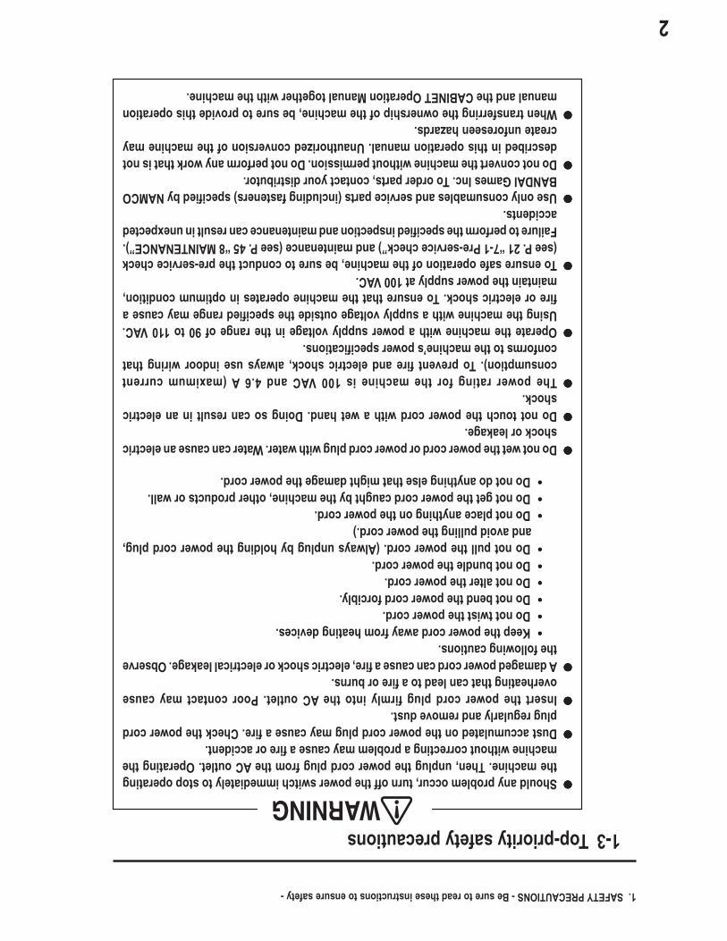
1-3Top-priority safety precautions
zzzzzShould any problem occur, turn off the power switch immediately to stop operatingthe machine. Then, unplug the power cord plug from the AC outlet. Operating themachine without correcting a problem may cause a fire or accident.
zzzzzDust accumulated on the power cord plug may cause a fire. Check the power cordplug regularly and remove dust.
zzzzzInsert the power cord plug firmly into the AC outlet. Poor contact may causeoverheating that can lead to a fire or burns.
zzzzzA damaged power cord can cause a fire, electric shock or electrical leakage. Observethe following cautions.iiiiiKeep the power cord away from heating devices.iiiiiDo not twist the power cord.iiiiiDo not bend the power cord forcibly.iiiiiDo not alter the power cord.iiiiiDo not bundle the power cord.iiiiiDo not pull the power cord. (Always unplug by holding the power cord plug,
and avoid pulling the power cord.)iiiiiDo not place anything on the power cord.iiiiiDo not get the power cord caught by the machine, other products or wall.iiiiiDo not do anything else that might damage the power cord.
zzzzzDo not wet the power cord or power cord plug with water. Water can cause an electricshock or leakage.
zzzzzDo not touch the power cord with a wet hand. Doing so can result in an electricshock.
zzzzzThe power rating for the machine is 100 VAC and 4.6 A (maximum currentconsumption). To prevent fire and electric shock, always use indoor wiring thatconforms to the machine’s power specifications.
zzzzzOperate the machine with a power supply voltage in the range of 90 to 110 VAC.Using the machine with a supply voltage outside the specified range may cause afire or electric shock. To ensure that the machine operates in optimum condition,maintain the power supply at 100 VAC.
zzzzzTo ensure safe operation of the machine, be sure to conduct the pre-service check(see P. 21 “7-1 Pre-service check”) and maintenance (see P. 45 “8 MAINTENANCE”).Failure to perform the specified inspection and maintenance can result in unexpectedaccidents.
zzzzzUse only consumables and service parts (including fasteners) specified by NAMCOBANDAI Games Inc. To order parts, contact your distributor.
zzzzzDo not convert the machine without permission. Do not perform any work that is notdescribed in this operation manual. Unauthorized conversion of the machine maycreate unforeseen hazards.
zzzzzWhen transferring the ownership of the machine, be sure to provide this operationmanual and the CABINET Operation Manual together with the machine.
WARNING

3
1. SAFETY PRECAUTIONS - Be sure to read these instructions to ensure safety -
WARNING
1-4Description of warning labels attached to the machine
zzzzzThe warning labels describe important safety precautions. Observe the following:iiiiiTo make sure that the warning labels attached to the machine are easily legible,
install the machine at a proper location with ample illumination and keep thelabels clean at all times. Also, make sure that the labels are not hidden behindanother game machine or other objects.
iiiiiDo not remove or alter the warning labels.iiiiiRegarding the warning labels attached on the Cabinet Assy, refer to the separate
CABINET Operation Manual.iiiiiIf the warning labels become dirty or damaged, replace them with new labels. To
order warning labels, contact your distributor.
zzzzzFor the details of warning labels attached on the Cabinet Assy, refer to the CABINETOperation Manual.

4
CONTENTSINTRODUCTION
1.SAFETY PRECAUTIONS - Be sure to read these instructions to ensure safety -..........................11-1Magnitudes of risk..........................................................................................................................................11-2Definition of the term “technician”...................................................................................................................11-3Top-priority safety precautions.......................................................................................................................21-4Description of warning labels attached to the machine..................................................................................3
CONTENTS..................................................................................................................................................4
2.SPECIFICATIONS..................................................................................................................................7
3.CHECKING THE PACKAGE CONTENTS.............................................................................................8
4.OVERALL CONSTRUCTION (Names of Parts).................................................................................10
5.INSTALLATION AND ASSEMBLY.......................................................................................................115-1Installation conditions...................................................................................................................................11
5-1-1Locations to avoid...............................................................................................................................115-1-2Play zone of installed machine............................................................................................................12
5-2Required dimensions of carry-in passage (such as doors and corridors)...................................................135-3Installation and assembly.............................................................................................................................14
5-3-1Adjusting the level adjusters...............................................................................................................145-3-2Connecting the power cord and ground lead......................................................................................145-3-3Inserting the USB key - To be conducted by a technician only -.........................................................145-3-4Installing the POP................................................................................................................................16
5-4Turning on the power switches....................................................................................................................175-5Installing the vendor POP.............................................................................................................................18
6.MOVING AND TRANSPORTING.........................................................................................................19
7.OPERATION.........................................................................................................................................207-1Pre-service check........................................................................................................................................21
7-1-1Safety check (before power ON).........................................................................................................217-1-2Function check (after power ON)........................................................................................................21
7-2How to play..................................................................................................................................................227-3Adjustment...................................................................................................................................................23
7-3-1Turning on the power switches...........................................................................................................237-3-2Adjustment switches...........................................................................................................................24
7-4Test mode.....................................................................................................................................................257-4-1Test mode menu..................................................................................................................................257-4-2Exiting from the Test mode..................................................................................................................26

5
CONTENTS
7-4-3Display test (DISPLAY TEST).............................................................................................................277-4-4Sound test (SOUND TEST)................................................................................................................287-4-5JVS status (JVS STATUS)..................................................................................................................307-4-6Input test (INPUT TEST).....................................................................................................................317-4-7Card reader/writer test (CARD RW TEST)..........................................................................................327-4-8Game options (GAME OPTIONS).......................................................................................................357-4-9Coin options (COIN OPTIONS)...........................................................................................................377-4-10Clock setting (CLOCK SETTING)...................................................................................................... 397-4-11Close time setting (CLOSE TIME SETTING)......................................................................................407-4-12Bookkeeping (BOOKKEEPING).........................................................................................................427-4-13Data clear (DATA CLEAR)..................................................................................................................45
8.MAINTENANCE...................................................................................................................................458-1Maintenance and inspection........................................................................................................................45
8-1-1Inspection items..................................................................................................................................45(1)Inspection of level adjusters.........................................................................................................45(2)Inspection of the power cord plug................................................................................................45(3)Inspection of screws for looseness..............................................................................................45
8-2Troubleshooting...........................................................................................................................................468-2-1General - To be conducted by a technician only -...............................................................................468-2-2Error messages - To be conducted by a technician only -..................................................................47
8-3Removing and installing Assys and parts.....................................................................................................488-3-1Replacing the Main Unit Assy - To be conducted by a technician only -.............................................488-3-2Replacing the HDD - To be conducted by a technician only -.............................................................50
9.DISCARDING THE MACHINE.............................................................................................................52
10.PARTS LIST.........................................................................................................................................5410-1General........................................................................................................................................................5410-2Cabinet Assy................................................................................................................................................55
11.WIRING DIAGRAM..............................................................................................................................57

6
CONTENTS

7
2. SPECIFICATIONS
800 8201700
(1)Rated power supply110-120VAC (50/60Hz), 220-240 VAC (50/60Hz)(2)Maximum power consumptionCabinet (P1) Assy:470W (110-120VAC power supply),
463W (220-240VAC power supply)Cabinet (P2) Assy:223W (110-120VAC power supply),
227W (220-240VAC power supply)(3)Maximum current consumptionCabinet (P1) Assy:4.3A (110-120VAC power supply),
2.2A (220-240VAC power supply)Cabinet (P2) Assy:2.2A (110-120VAC power supply),
1.1A (220-240VAC power supply)(4)Display device32-inch LCD monitor(5)Dimensions820 (W) x 800 (D) x 1,700 (H) mm
(6)WeightAs installed140 kg

8
3. CHECKING THE PACKAGE CONTENTSThe product package contains the following parts.
zzzzzMake sure all the parts shown below are contained in the product package.zzzzzIf parts are missing, contact your distributor.
Product package and included accessories

9
3. CHECKING THE PACKAGE CONTENTS
No.NameSpecificationQty
1TEKKEN 6 BLOODLINE REBELLIONThis manual1SD-S Operation Manual
2CABINET Operation Manual1
3Torx wrench4 mm across flats (for M5)1
4Dummy card (EXP)1
5Vendor POP (EXP)1
6Poster (B)1
7Poster (C)1
8Fighting technique panel (A) (EXP)2
9Fighting technique panel (B) (EXP)2
10Maintenance key2
11Coin box key2
12USB key (for EXP)Black sticker with T6B* indication is affixed1
iiiii Accessory list

10
4. OVERALL CONSTRUCTION (Names of Parts)zzzzzRegarding the construction of the cabinet, refer to the separate CABINET Operation
Manual.
This following shows a cabinet for the TEKKEN 6 BLOODLINE REBELLION SD-Sgame.
Game PC Board
STD Connector PC Board
Signboard sheet
Instruction sheet (EXP)
Card Reader Assy (P1 side)
Card Reader Assy (P2 side)

11
WARNING
WARNING
5. INSTALLATION AND ASSEMBLY
zzzzzInstall the machine according to the instructions and procedures in this operationmanual. Failure to follow the specified procedures may result in a fire, electric shock,injury, or machine malfunction.
zzzzzInsert the power cord plug firmly into the AC outlet. Poor contact may causeoverheating that can lead to a fire or burns.
zzzzzBe sure to connect the ground lead. Operating the machine without connecting theground lead can result in an electric shock if electric leakage occurs (see P. 24 “5-4Connecting the power cord and ground lead” in the separate CABINET OperationManual).
zzzzzInstall the machine securely to the floor by using the level adjusters. Unstable machineinstallation can result in an accident or injury (see P. 23 “5-3 Adjusting the leveladjusters” in the separate CABINET Operation Manual).
5-1Installation conditions
5-1-1Locations to avoid
zzzzzThe machine is designed for indoor use. Never install the machine outdoors or atany of the following locations:iiiiiPlace in direct sunlightiiiiiPlace exposed to rain or water leakageiiiiiDamp placeiiiiiDusty placeiiiiiClose to heating devicesiiiiiHot placeiiiiiExtremely cold placeiiiiiPlace where dew condensation may occur due to temperature differencesiiiiiPlace where the machine may become an obstruction in emergencies (such as
near emergency exit) and place where fire extinguisher or similar equipment isinstalled
iiiiiUnstable place or location where vibrations are produced
12
5. INSTALLATION AND ASSEMBLY
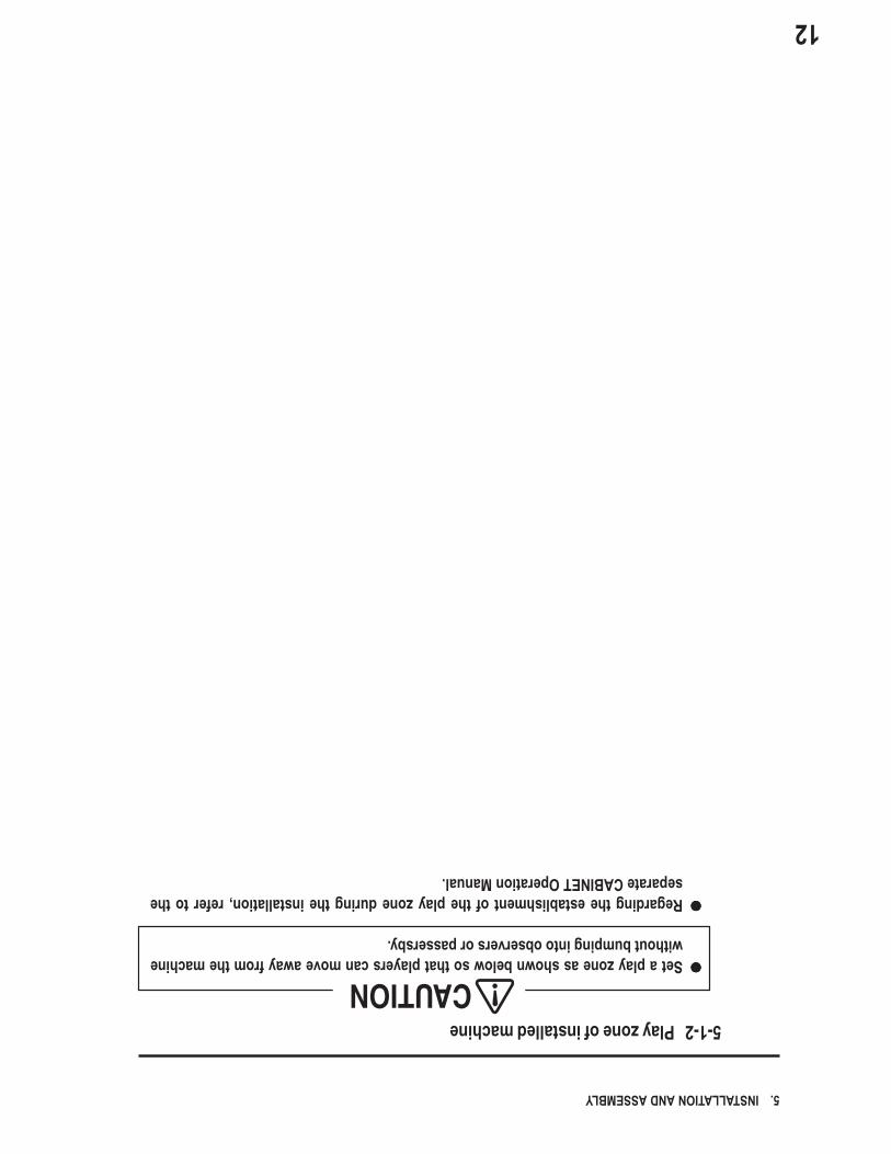
CAUTION5-1-2Play zone of installed machine
zzzzzSet a play zone as shown below so that players can move away from the machinewithout bumping into observers or passersby.
zzzzzRegarding the establishment of the play zone during the installation, refer to theseparate CABINET Operation Manual.

13
5. INSTALLATION AND ASSEMBLY
5-2Required dimensions of carry-in passage (such as doorsand corridors)
The doors and passages must be larger than the dimensions indicated below so that themachine can be carried to the installation site. The dimensions of the product in the ship-ping condition are as follows:
820 (W) x 800 (D) x 1,700 (H) mm. Weight: 140 kg
By referring to the dimensions indicated above, make sure in advance that the machinecan be carried smoothly to the installation site.
zzzzzRegarding the separation of the machine into Assys and components, refer to theseparate CABINET Operation Manual.
800 820
1700

14
5. INSTALLATION AND ASSEMBLY
WARNING
5-3Installation and assembly5-3-1Adjusting the level adjusterszzzzzRegarding the adjustment of the level adjusters of the machine, refer to the separate
CABINET Operation Manual.
5-3-2Connecting the power cord and ground leadzzzzzRegarding the connection of the power cord and ground lead, refer to the separate
CABINET Operation Manual.
5-3-3Inserting the USB key - To be conducted by a technician only -
zzzzzTo protect the service staff and other people from an electric shock, accident andinjury, and to prevent damage to the electrical circuitry of the machine, always turnoff the power switches before initiating the described task.
zzzzzThe USB key provided with the product is designed exclusively for thisgame machine. Never use it in any other machine. Also, do not insert anyother USB key into this machine. Failure to observe this instruction canresult in equipment malfunctions.
zzzzzMake sure that the power switch of the machine is turned off beforeinserting the USB key.
zzzzzBe sure to install one USB key to each Game PC Board.
Turn off the main power switch of the machine.(See P. 17 “5-4 Turning on the power switches of the cabinet” .)Remove the one Phillips truss screw (M4 x 10). Using the provided maintenancekey, open and dismount the maintenance door.
Phillips truss screw �(M4 x 10)
Maintenance key
Maintenance door
15
5. INSTALLATION AND ASSEMBLY
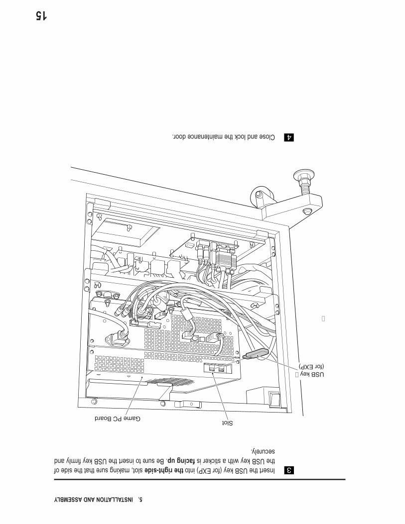
Insert the USB key (for EXP) into the right-side slot, making sure that the side ofthe USB key with a sticker is facing up. Be sure to insert the USB key firmly andsecurely.
USB key �(for EXP)
Game PC Board
�
Slot
Close and lock the maintenance door.
16
5. INSTALLATION AND ASSEMBLY
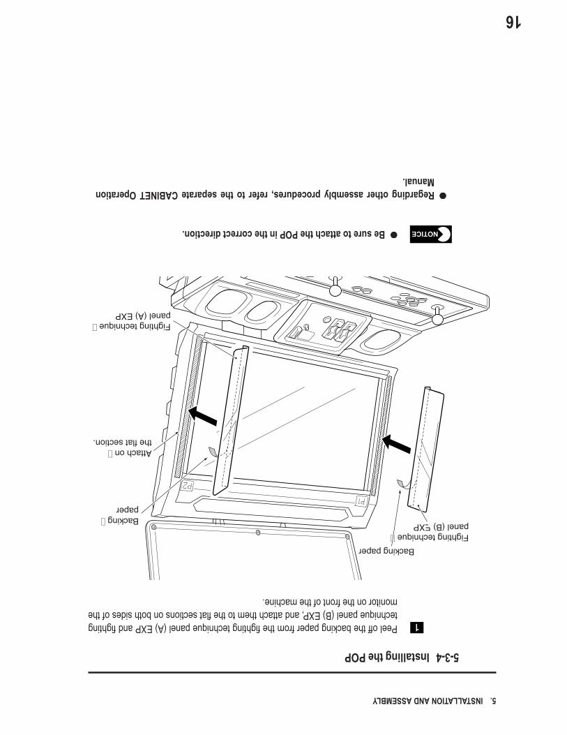
5-3-4Installing the POP
Peel off the backing paper from the fighting technique panel (A) EXP and fightingtechnique panel (B) EXP, and attach them to the flat sections on both sides of themonitor on the front of the machine.
zzzzzBe sure to attach the POP in the correct direction.
zzzzzRegarding other assembly procedures, refer to the separate CABINET OperationManual.
Fighting technique �panel (A) EXP
Fighting technique �panel (B) EXP
Backing paper
Backing �paper
Attach on �the flat section.

17
5. INSTALLATION AND ASSEMBLY
5-4Turning on the power switches
Turn on the main power switch located on the Cord Box Assy.
Remove the one Phillips truss screw (M4 x 10) from the maintenance door on thefront side of the machine, unlock the lock using the maintenance key provided withthe Cabinet Assy, and open the maintenance door. (See P. 14 “5-3-3 Inserting theUSB key” )
Turn on the sub-power switch.
ON
OFF
Main power switch
Ground �terminal
Power cord
Cord Box Assy
Sub-power switch
ON
OFF
Phillips truss screw (M4 x 10)
Maintenance door key
Maintenance door
18
5. INSTALLATION AND ASSEMBLY
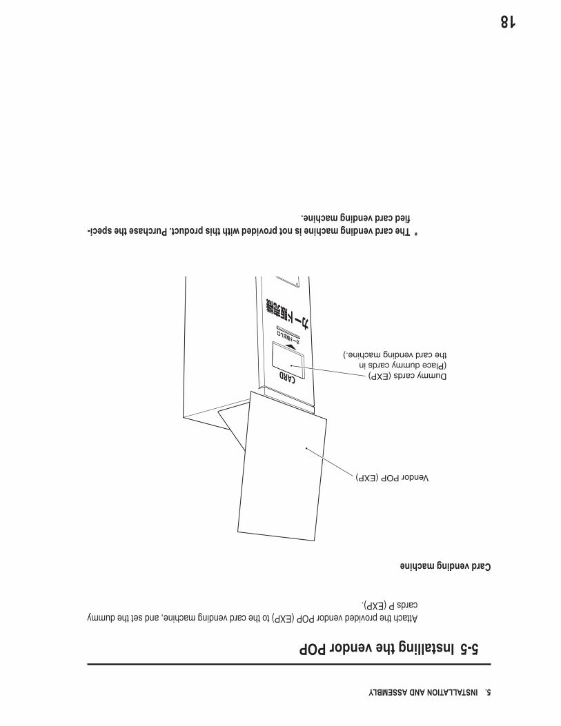
5-5Installing the vendor POP
Attach the provided vendor POP (EXP) to the card vending machine, and set the dummycards P (EXP).
Card vending machine
*The card vending machine is not provided with this product. Purchase the speci-fied card vending machine.
Vendor POP (EXP)
Dummy cards (EXP)(Place dummy cards in the card vending machine.)

19
6. MOVING AND TRANSPORTINGzzzzzRegarding the relocation and transportation of the machine, refer to the separate
CABINET Operation Manual.

20
WARNING
7. OPERATION
zzzzzShould any problem occur, turn off the power switch immediately to stop operatingthe machine. Then, unplug the power cord from the AC outlet. Operating the machinewithout correcting problems may cause a fire or accident.
zzzzzDust accumulated on the power cord plug may cause a fire. Check the power cordplug regularly and remove dust.
zzzzzInsert the power cord plug firmly into the AC outlet. Poor contact may causeoverheating that can lead to a fire or burns.
zzzzzBefore operating the machine, check to make sure that the machine has been installedaccording to the specified instructions (see P. 11 “5. INSTALLATION ANDASSEMBLY”). If the machine is installed improperly, a fire, electric shock, injury ormalfunction may result.
zzzzzThe warning labels describe important precautions. Observe the following. (Regardingthe label attachment locations, see P. 3 “1-4 Description of warning labels attachedto the machine.”)iiiiiTo make sure that the warning labels attached to the machine are easily legible,
install the machine at a proper location with ample illumination and keep thelabels clean at all times. Also, make sure that the labels are not hidden behindanother game machine or other objects.
iiiiiDo not remove or alter the warning labels.iiiiiIf warning labels become dirty or damaged, replace them with new labels. To
order warning labels, contact your distributor.zzzzzTo ensure safe operation of the machine, be sure to conduct the pre-service check
(see P. 21 “7-1 Pre-service check”) and maintenance (see P. 45 “8 MAINTENANCE”).Failure to perform the specified inspection and maintenance can result in unexpectedaccidents.

21
7. OPERATION
7-1Pre-service check
Check the items described below before commencing operation.If any problem is found, take corrective measures by referring to “8-2 Troubleshooting” onpage 46.
7-1-1Safety check (before power ON)
zzzzzTo prevent accidents and injury, be sure to check the following items beforecommencing operation.
(1)Are all warning indications legible?(See “1-4 Description of warning labels attached to the machine” on page 3 of theprovided CABINET Operation Manual.)
(2)Are all level adjusters adjusted properly so that the machine is not wobbly?(See P. 23 “5-3 Adjusting the level adjusters.”)
(3)Is the play zone established as specified?(See P. 12 “5-1-2 Play zone of installed machine.”)
(4)Is the power cord routed properly so that players and other people will not trip overthe cable?
Check the following items after turning on the power switches. If any abnormality is found,turn off the power switch immediately and stop operating the machine. Then, unplug thepower cord from the AC power outlet and contact your distributor.
(5)Is any part of the power cord or plug abnormally hot?(6)Does touching the machine give an electrical shock?(7)Is there a burning smell, abnormal noise or vibration?(8)Is there any other sign of abnormality or malfunction?
7-1-2Function check (after power ON)
(1)Sound check (Check that sound is produced by all speakers.)(See P. 28 “7-4-4 Sound test (SOUND TEST).”)
(2)Fluorescent lamp check (Check that the lamp lights.)(3)Display check (Check that the LCD monitor displays images.)
(See P. 27 “7-4-3 Display test.”)(4)Does card reader/writer operate properly?
(See P. 32 “7-4-7 Card reader/writer test.”)
WARNING

22
7. OPERATION
CAUTION7-2How to play
zzzzzIf a player becomes sick due to game images or stimulation by light, have the personstop playing the game immediately and let him/her rest.
zzzzzIn rare cases, stimulation by lights or video images can cause convulsion or a loss ofconsciousness. If this happens, advise the player to consult a doctor as soon aspossible.When pre-school children play the game, request their parents or guardians to observethe children.
Explanation of the game systemThe game system and play instructions are described on the instruction sheet (EXP) andvendor POP (EXP) provided with the product.
Methods of controlling the game characterThe game characters and control methods are described on the fighting technique panels(A) and (B) EXP provided with the product.

23
7. OPERATION
7-3Adjustment7-3-1Turning on the power switches
Turn on the main power switch located on the Cord Box Assy.
Move to the front side of the machine. Remove the Phillips truss screw (M4 x 10)from the maintenance door, unlock the door using the maintenance key suppliedwith the Cabinet Assy, and dismount the maintenance door. (See P. 14 “5-3-3 In-serting the USB key.”)
Turn on the sub-power switch and reinstall the maintenance door by following theremoval sequence in reverse.
ON
OFF
Main power switch
Power cord
Cord Box Assy
Sub-power switch
ON
OFF
Phillips truss screw (M4 x 10)
Maintenance door key
Maintenance door

24
7. OPERATION
7-3-2Adjustment switches
To access the adjustment switches, open the operation panel cover using the mainte-nance key.(See “7-2-2 Opening and closing the operation panel” on page 38 of the separate CABI-NET Operation Manual provided with the product.)
(a)Service switch (red)Press this switch to increase the credit count without activating the coin counter.
(b)Test switch (red)Press this switch in the game mode to enter the test mode.
(c)Sound volumeUse this dial to adjust the speaker sound level.
(d)Monitor adjustment switchesThese switches are used only for the adjustment of the display monitor.
(d) Monitor adjustment switches
(b) Test switch (red)
(a) Service switch (red)
(c) Sound volume
Adjustment �switches
Operation panel key

25
7. OPERATION
7-4Test mode7-4-1Test mode menu
To make adjustments, switch from the game mode to the Test mode, and display the testmode menu screen.
Turn on the power switches of the Cabinet Assy, and wait until the Attract screenappears.
Press the Test switch on the Cabinet Assy to activate the Test mode. (See P. 24 “7-3-2 Adjustment switches.”)The screen displays the adjustment items.
Move the P1 8-direction lever up or down to select an item. The selected item isindicated in red.
Test mode menu screen
MENU2008/12/03(WED)10:15:30
LOADED SOFTWARE: SERIAL NUMBER:000000-00000
SOFTWARE UPDATEDISPLAY TESTSOUND TESTJVS STATUSINPUT TESTCARD RW TESTGAME OPTIONSCOIN OPTIONSCLOCK SETTINGCLOSE TIME SETTINGBOOKKEEPINGDATA CLEAREXIT & SAVE
SELECT :P1-UP/DOWN ENTER :P1-BUTTON 1
Software version�Serial number��Software update (not used in normal operation)�Display test Refer to 7-4-3.�Sound test Refer to 7-4-4.�JVS status Refer to 7-4-5.�Input test Refer to 7-4-6.�Card RW test Refer to 7-4-7.�Game options Refer to 7-4-8.�Coin options Refer to 7-4-9.�Clock setting Refer to 7-4-10.�Close time setting Refer to 7-4-11.�Bookkeeping Refer to 7-4-12.�Data clear Refer to 7-4-13.
P1 8-direction lever
P1 sideP2 side

26
7. OPERATION
Press the P1 Button switch 1 to enter the selection.The screen for the selected test appears.
Make an adjustment for the selected test item.Regarding the adjustment method, refer to the applicable section in “7-4-3 Displaytest” (page 27) to “7-4-13 Data clear” (page 43).
7-4-2Exiting from the test mode
After making adjustments, return to the test mode menu screen.
Select “EXIT & SAVE,” and press the P1 Button switch 1.The test mode ends, and the display returns to the Attract screen.
zzzzzBe sure to use the method described above to exit from the test mode. Ifthe above procedure is not followed to exit from the test mode, theadjustments (setting changes or new settings) will not be reflected properly.
P1 Button switch 1
P1 sideP2 side
P1 8-direction leverP1 Button switch 1
P1 sideP2 side

27
7. OPERATION
7-4-3Display test (DISPLAY TEST)
This screen is used to check or adjust the display.
Select “DISPLAY TEST” on the test mode menu screen (see page 25), and pressthe P1 Button switch 1. The Display Test screen appears. There are two types ofDisplay Test screen as described below.
1.Color BarThis screen is used to check the contrast and color balance of displayed im-ages.
2.ConvergenceThis screen is used to check the image display size, display position, aspectratio and distortion.
Each time the P1 Button switch 1 is pressed, the screen indication changes alter-nately between the above-mentioned two screens. Select the screen according tothe item to be checked or adjusted.* Regarding the adjustment method, refer to the CABINET Operation Manual.
After the confirmation or adjustments, press the P1 Start switch to return to the testmode menu screen (see page 25).
To exit from the test mode, follow the procedure described in “7-4-2 Exiting from thetest mode” on page 26.
P1 8-direction leverP1 Button switch 1
P1 Start switch
P1 sideP2 side

28
7. OPERATION
7-4-4 Sound test (SOUND TEST)
This screen is used to adjust the sound level and conduct a stereo check.
Select “SOUND TEST” on the test mode menu screen (see page 25), and pressthe P1 Button switch 1. The Sound Test screen appears.
When the P1 Button switch is pressed, a test sound is produced from the left speakerfirst, followed by the right speaker, and then by both speakers.
*The sound level can be adjusted by using the sound volume located on eachCabinet Assy. (See P. 24 “7-3-2 Adjustment switches.”)
Indicates the audio channel �in output operation.
SOUND TEST
POSITION:OFF
CHECK SOUND: P1-BUTTON1EXIT: P1-START
Sound Test screen
P1 8-direction leverP1 Button switch 1
P1 sideP2 side
29
7. OPERATION
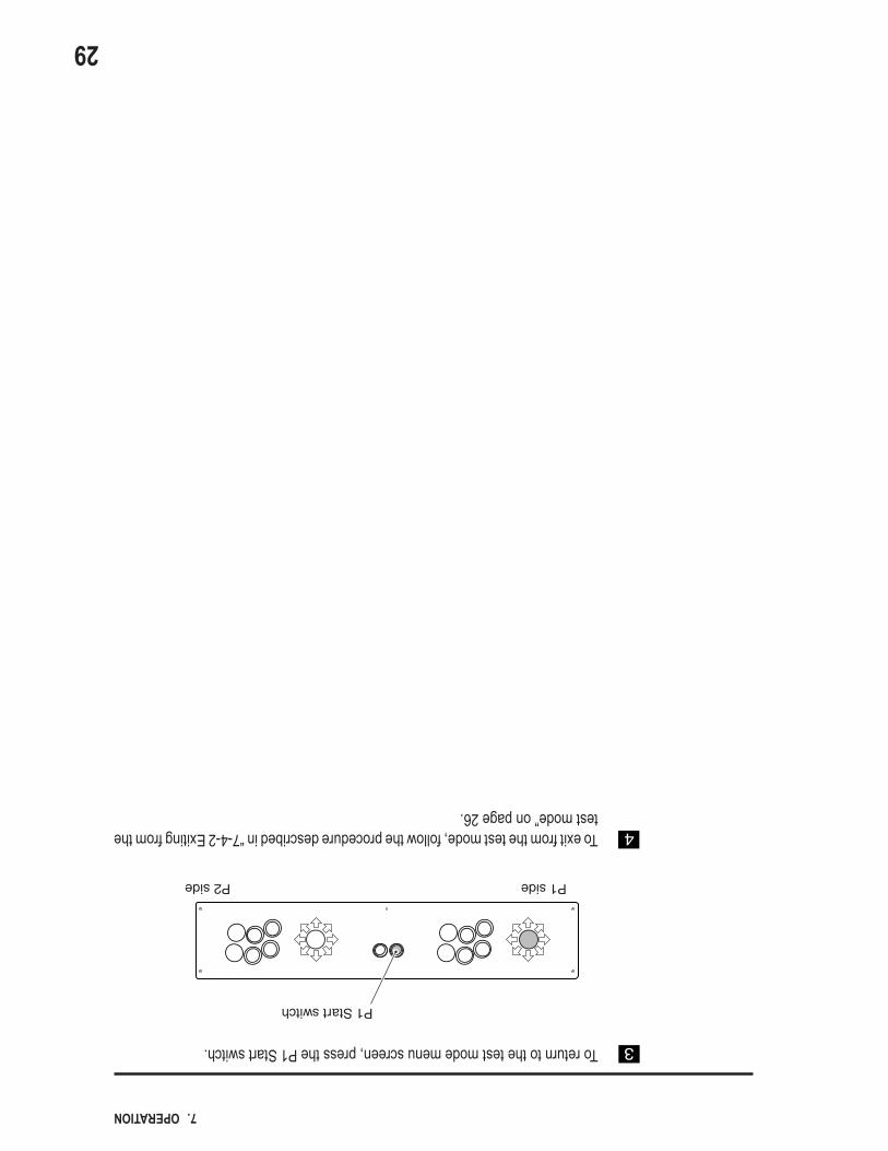
To return to the test mode menu screen, press the P1 Start switch.
To exit from the test mode, follow the procedure described in “7-4-2 Exiting from thetest mode” on page 26.
P1 Start switch
P1 sideP2 side
30
7. OPERATION
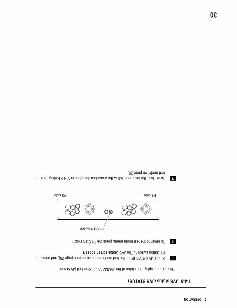
7-4-5JVS status (JVS STATUS)
This screen displays the status of the JAMMA Video Standard (JVS) cabinet.
Select “JVS STATUS” on the test mode menu screen (see page 25), and press theP1 Button switch 1. The JVS Status screen appears.
To return to the test mode menu, press the P1 Start switch.
To exit from the test mode, follow the procedure described in “7-4-2 Exiting from thetest mode” on page 26.
P1 Start switch
P1 sideP2 side

31
7. OPERATION
7-4-6Input test (INPUT TEST)
This screen is used to test the switches such as the buttons on the control panel.
Select “INPUT TEST” on the test mode menu screen (see page 25), and press theP1 Button switch 1. The Input Test screen appears.
Operate the levers and button switches on the control panel one by one, and checkthat the corresponding indications on the screen change to red.
*When the levers and button switches on the control panel and the service switchon the cabinet are operated, the corresponding indications on the screen changeto red.
*Each operation increments the numeric value of COIN 1 by one. At the sametime, the coin counter counts up.
zzzzzIf the screen indications do not change according to the lever/buttonoperations, the game cannot be played properly. If this happens, refer to“8-2 Troubleshooting” on page 46.
To return to the test mode menu screen, press the P1 Button switches 1 and 2simultaneously.
P1 Button switch 1P1 Button switch 2
P1 sideP2 side
To exit from the test mode, follow the procedure described in “7-4-2 Exiting from thetest mode” on page 26.
P1 Start switch
P1 8-direction �lever
DIP switches on �Game PC Board
P2 Start switch
P2 side P1 side
P2 8-direction �lever
P2 Button switch
Method of returning to �the test mode menu screen
P1 Button switch
Number of coin switch �operations (default: 0)
INPUT TEST P1
STARTSERVICEUPDOWNLEFTRIGHTTEST
BUTTON1 BUTTON2BUTTON3 BUTTON4
P2
START
UPDOWNLEFTRIGHT
BUTTON1 BUTTON2BUTTON3 BUTTON4
COIN 1:000 COIN 2:000DIPSW 1:OFF 2:OFF 3:OFF 4:OFF 5:OFF 6:OFF 7:OFF 8:OFF
EXIT: P1-BUTTON 1&2
...
.........
Input Test screen

32
7. OPERATION
7-4-7Card reader/writer test (CARD RW TEST)
This screen is used to test the card reader/writer unit and TEKKEN-NET ID card (hereaf-ter referred to as a “card”).
Select “CARD RW TEST” on the test mode menu screen (see page 25), and pressthe P1 Button switch 1. The Card RW Test screen appears.
When a card is inserted in the card reader/writer unit, the card access code (20-digit code) is displayed.
CARD RW TEST
P1 CARD RW FOUND P2 CARD RW FOUND
INSERT CARD INSERT CARD
SELECT: P1(P2)-UP/DOWNENTER: P1(P2)-BUTTON1EXIT: P1-START
(A)
Card RW Test screen (1)
*Up to two stacked cards can be inserted.*The above screen appears when two cards are inserted in the card reader/writer
unit on the P1 side.*If a card not supported by the machine is inserted, “UNKNOWN CARD” is dis-
played in place of the access code.
CARD RW TEST
P1 CARD RW FOUND P2 CARD RW FOUND
CARD 1 00000 00000 00000 00000 INSERT CARDCARD 2 00000 00000 00000 00000
EJECT (P1) W/R TEST (P1)
SELECT: P1(P2)-UP/DOWNENTER: P1(P2)-BUTTON1EXIT: P1-START
Card RW Test screen (2)
“FOUND” is displayed when the card reader/writer unitis connected to the Game PC Board. “NOT FOUND” isdisplayed when the card reader/writer unit is notconnected.
(A)P1 CARD RW FOUND(P2 CARD RW FOUND)
[FOUND] OR [NOT FOUND]
Card RW unit status indicationItemDisplayRemarks

33
7. OPERATION
By inserting a new card is inserted into the card reader/writer unit, a test can beconducted for the card reader/writer unit. Move the P1 (or P2) 8-direction lever upor down to select “W/R TEST,” and press the P1 (or P2) Button switch 1 to executea test.
*The card used in the test returns to default condition, so it can be reused.
*The above screen appears when “W/R TEST” is executed for the card reader/writer unit on the P2 side.
*When the test ends successfully, “W/R TEST OK” is indicated on the right side ofthe “CARD 1” indication. If “W/R TESTING” is displayed, the card reader/writerunit or card may be faulty.
P1 8-direction lever
P1 Button switch 1
P2 8-direction leverP2 Button switch 1
P1 sideP2 side
Card RW Test screen (3)
CARD RW TEST
P1 CARD RW FOUND P2 CARD RW FOUND
INSERT CARDCARD1 W/R TEST OK00000 00000 00000 00000
EJECT (P2)W/R TEST (P2)
SELECT: P1(P2)-UP/DOWNENTER: P1(P2)-BUTTON1EXIT: P1-START
34
7. OPERATION
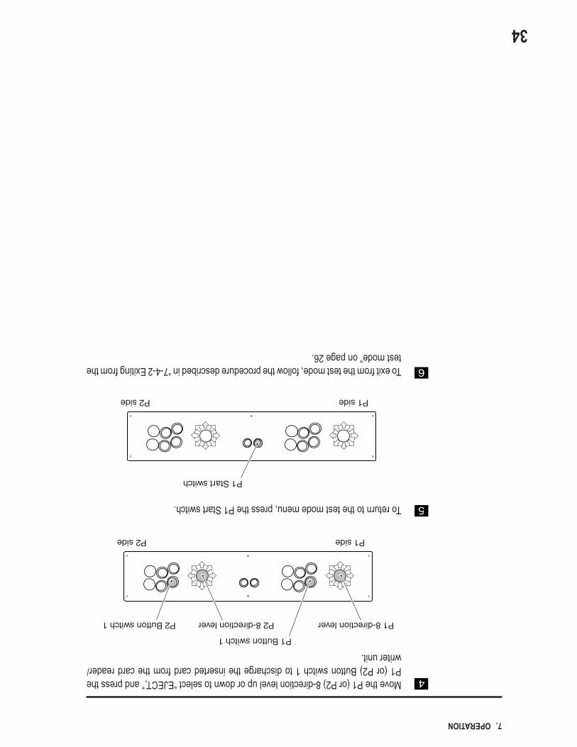
Move the P1 (or P2) 8-direction level up or down to select “EJECT,” and press theP1 (or P2) Button switch 1 to discharge the inserted card from the card reader/writer unit.
P1 8-direction lever
P1 Button switch 1
P2 8-direction leverP2 Button switch 1
P1 sideP2 side
P1 Start switch
P1 sideP2 side
To return to the test mode menu, press the P1 Start switch.
To exit from the test mode, follow the procedure described in “7-4-2 Exiting from thetest mode” on page 26.

35
7. OPERATION
7-4-8Game options (GAME OPTIONS)
This screen is used to set game details.
Select “GAME OPTIONS” on the test mode menu screen (see page 25), and pressthe P1 Button switch 1. The Game Options screen appears.
Operate the lever on the control panel to select an item and change its setting.
*Move the P1 8-direction lever up or down to select an item, and move the P1 8-direction lever to right or left to change the setting.
*The default setting is indicated in green.
Game Options screen
(A)�(B)�(C)�(D)�(E)�(F)�(G)�(H)�(I)�(J)�(K)�(L)�(M)�(N)��
GAME OPTIONS[DEFAULTS IN GREEN]
DIFFICULTY LEVEL:MEDIUMFIGHT COUNT<1P GAME>:2FIGHT COUNT<VS GAME>:2LIFE BAR<1P GAME>:NORMALLIFE BAR<VS GAME>:NORMALGUARD DAMAGE:OFFNEUTRAL GUARD:ONROUND TIME:60CHARACTER CHANGE AT CONTINUE:YESCHARACTER CHANGE AT VS GAME:NOSOUND IN ATTRACT MODE:YESEVENT MODE:OFFHIT COLOR:RED
ATTRACT MOVIE:ON
SELECT: P1-UP/DOWNMODIFY:P1-LEFT/RIGHTEXIT:P1-START
P1 8-direction lever
P1 sideP2 side

36
7. OPERATION
*1If a card is used, the game character cannot be changed even if the setting (J)has been set to “YES.”
To return to the test menu screen, press the P1 Start switch.
To exit from the test mode, follow the procedure described in “7-4-2 Exiting from thetest mode” on page 26.
P1 Start switch
P1 sideP2 side
Game difficulty level
Number of rounds required forwinning the game in single-playermode
Number of rounds required forwinning the game in versus gamemode
Energy level gauge in single-playermode
Energy level gauge in versus gamemode
Damage received on guard
Guard without lever operation
Time [sec] in one round
Change of game character forcontinuity game
Change of game character whenanother player barges in *1
Sound in Attract mode
ON: Game over for both playerswhen tournament mode game ends
Color of graphic effect of strikes
Movie shown in Attract mode
ItemOptionsDefaultRemarks setting(A)DIFFICULTY LEVEL
(B)FIGHT COUNT<1P GAME>
(C)FIGHT COUNT<VS GAME>
(D)LIFE BAR<1P GAME>
(E)LIFE BAR<VS GAME>
(F)GUARD DAMAGE
(G)NEUTRAL GUARD
(H)ROUND TIME
(I)CHARACTER CHANGE ATCONTINUE
(J)CHARACTER CHANGE ATVS GAME
(K)SOUND IN ATTRACTMODE
(L)EVENT MODE
(M)HIT COLOR
(N)ATTRACT MOVIE
[EASY] [MEDIUM] [HARD] [VERY HARD] [ULTRA HARD]
[1] [2] [3] [4] [5]
[1] [2] [3] [4] [5]
[-2] [-1] [NORMAL] [+1] [+2]
[-2] [-1] [NORMAL] [+1] [+2]
[ON] [OFF]
[ON] [OFF]
[30] [40] [60] [80] [99]
[YES] [NO]
[YES] [NO]
[YES] [NO]
[ON] [OFF]
[RED] [YELLOW]
[ON] [OFF]
[HARD]
[2]
[2]
[NORMAL]
[NORMAL]
[OFF]
[ON]
[60]
[YES]
[NO]
[YES]
[OFF]
[YELLOW]
[ON]
Game Options setting chart

37
7. OPERATION
7-4-9Coin options (COIN OPTIONS)
This screen is used to set the play fee and free play.
Select “COIN OPTIONS” on the test mode menu screen (see page 25), and pressthe P1 Button switch 1. The Coin Options screen appears.
Operate the lever on the control panel to select an item and change its setting.
*Move the P1 8-direction lever up or down to select an item, and move the P1 8-direction lever to right or left to change the setting.
*The default setting is indicated in green.
Coin Options screen
(A)�(B)�(C)��(D)
COIN OPTIONS [DEFAULTS IN GREEN]
START COST:1 COUNTINUE COST:1 COIN CHUTE1 MECHANICAL VALUE:1 COIN CHUTE2 MECHANICAL VALUE:1 FREE PLAY:NO
SELECT: P1-UP/DOWN MODIFY:P1-LEFT/RIGHTEXIT:P1-START
P1 8-direction lever
P1 sideP2 side

38
7. OPERATION
To return to the test mode menu screen, press the P1 Start switch.
Number of credits required for onenew game play
Number of credits required for onecontinuity game play
Number of credits added by oneoperation of Coin switch 1
Free play setting
ItemOptionsDefaultRemarks setting(A)START COST
(B)COUNTINUE COST
(C)COIN CHUTE1MECHANICAL VALUE
(D)FREE PLAY
[1] [2] [3] [4] [5] [6] [7] [8] [9]
[1] [2] [3] [4] [5] [6] [7] [8] [9]
[1] [2] [3] [4] [5] [6] [7] [8] [9]
[NO] [YES]
[1]
[1]
[1]
[NO]
Coin Options setting chart
To exit from the test mode, follow the procedure described in “7-4-2 Exiting from thetest mode” on page 26.
P1 Start switch
P1 sideP2 side

39
7. OPERATION
7-4-10 Clock setting (CLOCK SETTING)
This screen is used to set the clock of the Game PC Board.
Select “CLOCK SETTING” on the test mode menu screen (see page 25), and pressthe P1 Button switch 1. The Clock Setting screen appears.
Operate the lever on the control panel to select an item and change its setting.
*Move the P1 8-direction lever up or down to select an item, and move the P1 8-direction lever to right or left to change the setting.
*The day of the week indication is automatically set when the Year, Month andDay are changed.
To return to the test mode menu screen, press the P1 Start switch.
To exit from the test mode, follow the procedure described in “7-4-2 Exiting from thetest mode” on page 26.
Sets the year.�Sets the month.�Sets the day.�Sets the hour.�Sets the minute.
CLOCK SETTING
NOW 2007/12/03(MON) 10:15:30
YEAR:2007MONTH:12
DAY:01 HOUR:10 MINUTE:15
SELECT: P1-UP/DOWNMODIFY:P1-LEFT/RIGHTEXIT:P1-START
Clock Setting screen
P1 8-direction lever
P1 sideP2 side
P1 Start switch
P1 sideP2 side

40
7. OPERATION
7-4-11 Close time setting (CLOSE TIME SETTING)
This screen is used to set the arcade closing time. The machine stops allowing the use ofcards 15 minutes prior to the set time. The time can be set between 19:00 and 26:00 (2:00on the following day), or for 24-hour operation.The same closing time can be set to the same time on every day, or the closing time canbe set differently for each day of the week.
Select “CLOSE TIME SETTING” on the test mode menu screen (see page 25), andpress the P1 Button switch 1. The Close Time Setting screen appears.
Operate the lever on the control panel to select an item.
*Move the P1 8-direction lever up or down to select an item, and move the P1 8-direction lever to right or left to change the setting.
*The default setting is indicated in green.
P1 8-direction lever
P1 sideP2 side
�
Closed Time Setting screen (Week)
(A)�(B)�(C)�����
CLOSE TIME SETTING [DEFAULTS IN GREEN]
SCHEDULE TYPE:DAY
HOURS:24 MINUTES: 00
(A)�(B)�(C)����
CLOSE TIME SETTING [DEFAULTS IN GREEN]
SCHEDULE TYPE:WEEK
SUN HOURS:24MINUTES:00 MON HOURS:24 MINUTES:00 TUE HOURS:24 MINUTES:00 WED HOURS:24 MINUTES:00 THU HOURS:24 MINUTES:00 FRI HOURS:24 MINUTES:00 SAT HOURS:24 MINUTES:00
SELECT: P1-UP/DOWN MODIFY:P1-LEFT/RIGHTEXIT:P1-START
SELECT: P1-UP/DOWN MODIFY:P1-LEFT/RIGHTEXIT:P1-START
Closed Time Setting screen (Day)

41
7. OPERATION
P1 Start switch
P1 sideP2 side
Select daily setting [DAY] or weeklysetting [WEEK].*1
Set [HOURS] for closing timesetting.Select [ALL] for 24-hour operation.
Select [MINUTES] for close timesetting.*2
ItemOptionsDefaultRemarks setting(A)SCHEDULE TYPE
(B)HOURS
(C)MINUTES
[DAY] [[WEEK]
[24] [25] [26] [ALL] [19] [20] [21] [22] [23] [24] ...
[00] [15] [30] [45] [00] ...
[DAY]
[24]
[00]
Close Time Setting setting chart
To return to the test mode menu screen, press the P1 Start switch.
*1When [DAY] is selected, the same closing time applies to every day of the week.*2When [ALL] is selected, MINUTES will not be indicated.
To exit from the test mode, follow the procedure described in “7-4-2 Exiting from thetest mode” on page 26.
42
7. OPERATION
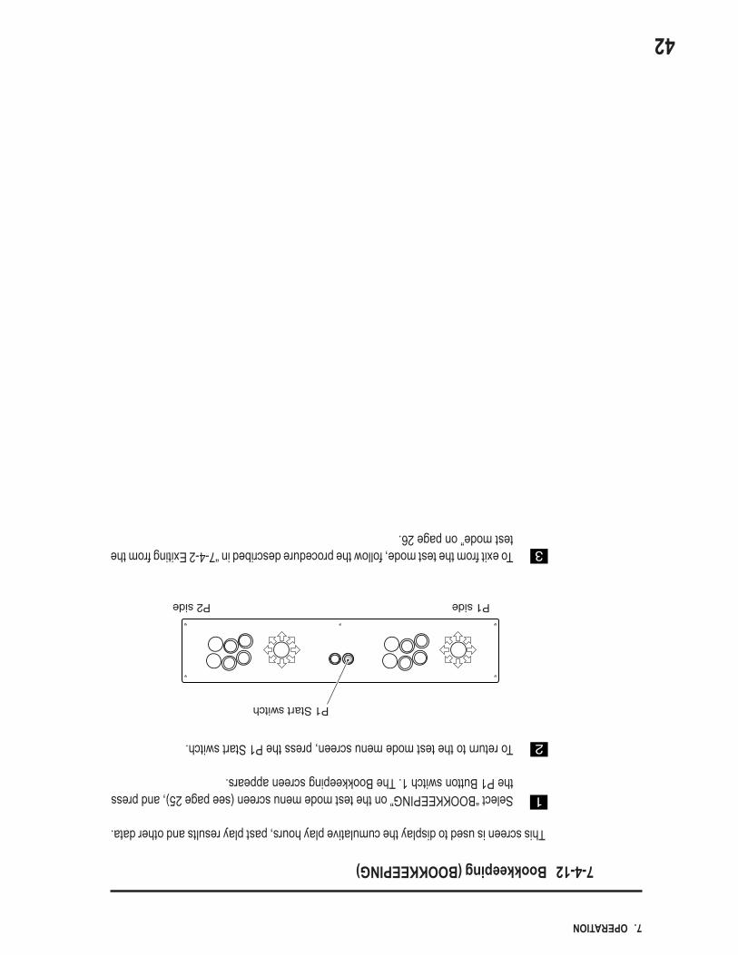
7-4-12 Bookkeeping (BOOKKEEPING)
This screen is used to display the cumulative play hours, past play results and other data.
Select “BOOKKEEPING” on the test mode menu screen (see page 25), and pressthe P1 Button switch 1. The Bookkeeping screen appears.
To return to the test mode menu screen, press the P1 Start switch.
To exit from the test mode, follow the procedure described in “7-4-2 Exiting from thetest mode” on page 26.
P1 Start switch
P1 sideP2 side

43
7. OPERATION
7-4-13 Data clear (DATA CLEAR)
This screen is used to delete data and to restore initial settings.
Select “DATA CLEAR” on the test mode menu screen (see page 25), and press theP1 Button switch 1. The Data Clear screen appears.
*Move the P1 8-direction lever up or down to select an item, and press the P1Button switch 1 to enter the selection. The display will show a setting confirma-tion screen.
Data Clear screen
(A)�(B)�(C)�(D)�(E)�(F)
DATA CLEAR
CANCELBOOKKEEPING CLEARRANKING DATA CLEARFLASH ROM DATA CLEARSET DEFAULTS ALL OPTIONSALL CLEAR
SELECT: P1-UP/DOWN ENTER:P1-BUTTON1EXIT:P1-START
FLASH ROM FORMAT(G)
P1 8-direction leverP1 Button switch 1
P1 sideP2 side
(A)CANCELCancels the current mode and displays the test mode menu.(B)BOOKKEEPING CLEARInitializes the bookkeeping data.(C)RANKING DATA CLEARInitializes the record of consecutive wins and others.(D)FLASH ROM DATA CLEARInitializes the data stored in the flash memory, such as ghost
characters and replay data.(E)SET DEFAULTS ALL OPTIONSReturns the settings to defaults.(F)ALL CLEARReturns all data and settings to defaults.(G)FLASH ROM FORMATFormats the flash ROM.
ItemDescriptionRemarksData Clear setting chart

44
7. OPERATION
To return to the test mode menu screen, press the P1 Start switch.
P1 Start switch
P1 sideP2 side
To exit from the test mode, follow the procedure described in “7-4-2 Exiting from thetest mode” on page 26.

45
WARNING
WARNING
8. MAINTENANCE
zzzzzBefore conducting maintenance (troubleshooting, repair, etc.), turn off the powerswitches to protect the service staff and other people from electrical shock, accidentsand injury.
8-1Maintenance and inspection
zzzzzConduct maintenance regularly to prevent unexpected accidents.zzzzzConduct a pre-service check everyday to prevent accidents.
(See P. 21 “7-1 Pre-service check.”)
8-1-1Inspection itemsCheck the following regularly.
(1)Inspection of level adjusters(1)Make sure that the machine is stably installed. (See “5-3 Adjusting the level
adjusters” on page 23 of the Cabinet Operation Manual.)
(2)Inspection of power cord plug(1)Make sure that the power cord is connected securely to the socket on the Cord
Box Assy of the machine.(2)If the connectors are covered with dust, clean them.(3)Check the power cord to make sure that the cable sheath is not cracked or
dirty. If there is any abnormality in the power cord, replace it with a new cord.
(3)Inspection of screws for loosenessCheck each screw to make sure that it is tightly fastened. If screws are loose,tighten them firmly.

46
8. MAINTENANCE
8-2Troubleshooting
zzzzzTo protect the service staff and other people from an electrical shock, accident andinjury, and to prevent damage to the electrical circuitry of the machine, always turnoff the power switches before initiating the described task.
zzzzzIf the generated problem is not described in “8-2 Troubleshooting” or if the correctivemeasure taken does not result in an improvement, turn off the power switchimmediately to stop operation, and contact your distributor. Operating the machinewith a problem left uncorrected can result in unexpected accidents.
zzzzzIn the event of a machine malfunction, first check to make sure that allconnectors are firmly connected.
zzzzzThe Game PC Board must be repaired by the supplier. Do not conduct aconductivity test using a tester. The internal voltage in the tester candamage the ICs on the PC board.
zzzzzWhen sending parts for repair, pack them carefully. When sending the GamePC Board, wrap them in sponge or bubble wrap, and place them in acorrugated cardboard box to protect against external impact.Be sure to attach the Repair Request form to the parts sent for repair.
zzzzzTo avoid the above condition and ensure smoother game play, if the erroror problem can be corrected by turning the Test switch On/Off, it isrecommended not to turn the power switch Off and On.
8-2-1General - To be conducted by a technician only -
WARNING
For other symptoms, refer to the CABINET Operation Manual.
SymptomPossible causeRemedyPageThe machine does notstart up.
The machine does notdispense cards.
48
17, 23
The connector of the Game PC Board isdisconnected.
The power switch was turned off while acard was still in the machine.
Insert the connector/Faston terminalfirmly.
Turn on the machine. The Game PCBoard checks the data on the card andthen automatically discharges the card.*If the card is not automatically dis-
charged, unlock the card reader/writerunit and remove the card by referringto the CABINET Operation Manual.

47
8. MAINTENANCE
8-2-2Error messages - To be conducted by a technician only -
SymptomPossible causeRemedyPageAn error occrred(8002****)
An error occurredduring the startoperation
Can not start. Thecorrect hard disk wasnot found.
USB KEY ERROR:NOT FOUND
USB KEY ERROR:WRONG KEY
USB KEY ERROR:CANNOT INITIALIZE*
USB KEY ERROR:FORMAT FAILED
USB MEMORYERROR
48, 50
14, 48
14
43
14
14
The HDD is not connected properly.The HDD or Game PC Board is faulty.
The USB key is not inserted correctly orthe Game PC Board is faulty.
USB key for another product is insertedin the machine.
The inserted USB key is for Tekken 6.
Initialization of the USB key failed atstartup.
Flash ROM formatting for the USB keyfailed.
USB memory stick was connectedtogether with the USB key when themachine started.
Replace the HDD or Game PC Board
Check the USB key for secure connec-tion.Replace the USB key or Game PCBoard.
Insert the correct USB key.*Insert the USB key (for EXP) for
“TEKKEN 6 BLOODLINE REBELLION”cabinet.
Execute “Flash ROM Format” in the Testmode.*If the same error message continues to
be displayed, replace the USB key.
Replace the USB key.
Disconnect the USB memory stick, andstart the machine.*Be careful not to disconnect the USB
key by mistake.
*Even if this error is displayed at startup, the machine can continue operation. However, the data of the ghost charac-ter will not be updated.

48
8. MAINTENANCE
WARNING
8-3Removing and installing Assys and parts8-3-1Replacing the Main Unit Assy - To be conducted by a technician only -
zzzzzTo protect the service staff and other people from an electric shock, accident andinjury, and to prevent damage to the electrical circuitry of the machine, always turnoff the power switches before initiating the described task.
Turn off the power switches of the machine.(See P. 17 “5-4 Turning on the power switches of the cabinet.”)
Remove the maintenance door. (See P. 14 “5-3-3 Inserting the USB key” .)
Disconnect the eight connectors and remove the USB key (for EXP).
Remove the two wing bolts (M4 x 20), and pull the PC board base forward andremove.
USB key (for EXP)
ConnectorsWing bolt (M4 x 20)
Wing bolt (M4 x 20)
PC board base
Connectors

49
8. MAINTENANCE
Remove the six spring washers (M6) and six hexagon nuts (M6), and dismount theGame PC Board.
Replace the Game PC Board.
Reinstall the parts by following the removal sequence in reverse.
zzzzzBe sure to insert the removed USB key into the new Game PC Board.Without the USB key, the game machine does not function properly. (SeeP. 14 “5-3-5 Inserting the USB key.”)
zzzzzWhen transporting the Game PC Board by itself, disconnect all theconnectors from the Game PC Board.
Hexagon nut (M6)
Spring washer (M6)Hexagon nut (M6)
Spring washer (M6)
Connector
Game PC Board
PC board base

50
8. MAINTENANCE
8-3-2Replacing the HDD - To be conducted by a technician only -
zzzzzThe following task should be performed by a technician only.zzzzzMake sure that the person performing the installation or connection is not
charged with static electricity. Static electricity can cause a productmalfunction or damage.
zzzzzDo not perform a conductivity test using a tester. The internal voltage inthe tester can damage the ICs on the PC board and render the PC boarduseless.
zzzzzTo protect the service staff and other people from an electric shock, accident andinjury, and to prevent damage to the electrical circuitry of the machine, always turnoff the power switches before initiating the described task.
Turn off the power switches of the machine.(See P. 17 “5-4 Turning on the power switches of the cabinet.”)
Remove the Game PC Board. (See P. 48 “8-3-1 Replacing the Game PC Board.”)
Remove the two Phillips pan-head screws (with flat and spring washers) (M3 x 6)on the front side of the Game PC Board, pull the top cover forward, and lift the frontside to remove.
WARNING
Top cover
Game PC Board
Tab claws
Phillips pan-head screw (with flat and spring washers) (M3 x 6)

51
8. MAINTENANCE
Disconnect the one connector, and dismount the HDD (for EXP) together with theHDD bracket.
Remove the four Phillips pan-head screws (with flat and spring washers) (No. 6-UNC x 4/16), dismount the HDD (for EXP) from the HDD bracket, and replace theHDD.
Reinstall the parts by following the removal sequence in reverse.
Phillips pan-head screw (with flat and spring washers) (No. 6-UNC x 4/16)
HDD bracket
HDD (for EXP)
T6B100*-NA-HDD0-A
HDD (for EXP)
HDD bracket
Connector

52
9. DISCARDING THE MACHINE
zzzzzWhen discarding the machine, the machine must be collected, transported anddiscarded in accordance with the local laws and regulations.
zzzzzWhen entrusting a third party to collect, transport and discard the machine, be sureto use specialized companies to perform each task.
WARNING

53
9. DISCARDING THE MACHINE

54
No.NameQtyType and ratingParts No.1Dummy card (EXP)1722-5672Vendor POP (EXP)1722-5683TEKKEN 6 BLOODLINE REBELLION1This manual722-570
SD-S Operation Manual4CABINET Operation Manual1719-705
10. PARTS LIST
10-1 General
55
10. PARTS LIST
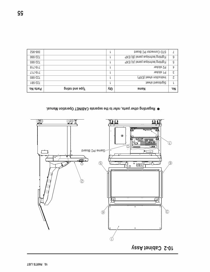
10-2 Cabinet Assy
No.NameQtyType and ratingParts No.1Signboard sheet1722-5812Instruction sheet (EXP)1722-5853P1 sticker1719-7174P2 sticker1719-7185Fighting technique panel (A) EXP1722-5656Fighting technique panel (B) EXP1722-5667STD Connector PC Board1306-952
zzzzzRegarding other parts, refer to the separate CABINET Operation Manual.
P1P2
Game PC Board

56
10. PARTS LIST

11. W
IRIN
G DI
AGRA
MS
57
Red Blk Blk
Red
Brn
Yw
Blu
Vio
Red Blk
Red Blk
Red Blk
Red Blk
Red Blk
Red Blk
Blk
Red Blk
Red Blk
Org
Grn
Wht
Gry
Blk
Org
Grn
Wht
Gry
Wht
Blk
Org
Grn
Red
Gry
Gry
Org
Grn
Blk
Blk
Blk
Blk
Blk
LtB
luLt
Blu
Grn
Org
Grn
/Yw
Yw
/Grn
Yw
/Grn
Vio
Pnk
Brn
Vio
Pnk Brn
Blk
Blk
Blk
Blk
Blk
Blk
Blk
Blk
Blk
Blk
Blk
Blk
Blk
Blu
Blu
Grn
Org
Wht
/Brn
Wht
/Blu
Wht
/Yw
Wht
/Yw
Wht
/Blu
Wht
/Brn
Red
Wht
/Brn
Wht
/Red
Wht
/Red
Wht
/Yw
Wht
/Blu
Wht
/Vio
Wht
/Blk
Wht
/Blk
(Blk
)W
ht/R
edW
ht/R
ed
Wht
/Blk
Wht
/Blk
Wht
Wht
/Gry
Wht
/Org
Wht
/Grn
Blk
Blk
Red
Org
Red
Brn
Yw
Blu
Vio
Pnk
Yw
/Grn
Org
Blk
Blk
Blk
Blk
Blk
Blk
Blk
Blk
Blk
Blk
Blk
Blk
Blk
Red
Blu
Blu
Org
Org
Wht
/Yw
Wht
/Yw
Wht
/Blu
Wht
/Blu
Wht
/Brn
Wht
/Brn
Grn
Grn
Brn
Brn
Blk
Blk
Blk
Blk
Vio
Vio
Pnk
Pnk
Yw
/Grn
Yw
/Grn
(Blk
)Lt
Blu
LtB
lu
Blk
Blk
Blk
Red
Red
Wht/YwWht/BluWht/Brn
OrgGrnBluPnkBrn
Wht/BlkWht/Blk
Wht
BlkBlk
Wht/Brn
Wht/Yw
Wht/GryWht/GrnWht/OrgWht/VioWht/Blu
Wht/RedWht/Red
BlkBlkBlk Blk
RedRed
VioYw/Grn
Yw/Grn
LtBlu
Brn
PnkVio
Wht/YwWht/BluWht/Brn
YwBlu
PnkBlu
BrnYw/Grn
VioLtBluBrnYw
GrnOrg
GrnWhtGry
Wht/Red
Wht/BlkWht/Blu
Blk
Org
Org
BlkBlk
BlkBlkBlkBlk
BlkBlkBlk
Red
RedOrg
Brn
YwYwYwYw
Wht
Red
Yw
Vio
Gry
Wht
Yw
Vio
Grn
/Yw
GryWht
Yw
Vio
Grn
/Yw
Grn
/Yw
Grn/Yw
Yw
Vio
Grn
/Yw
Grn
/Yw
Grn
/Yw
Grn
/Yw
Wht
Gry
Wht
Gry
Grn
/Yw
Grn
/Yw
Wht
Gry
Wht
Gry
Wht
Blk
Grn/Yw
GryWht
WhtWhtGry
Blk
Blk
Blk
Blk
Blk
Blk
Blk
Org
Org
Org
Org
Brn
Red
Blk
Blk
Blk
Red
Red
Brn
(Red
)
(Blu
)
Blk
Blk
Blk
Blk
Yw
Yw
Yw
Yw
Red
Wht
Blk
Blk
Blk
Blk
Wht
Gry
Yw
Yw
Yw
Wht
/Blk
Wht
/Blu
Wht
/Red
Yw
Brn
Yw
YwBlk
Blk
(Red
)
RedBlk
BlkOrg
1-core shielded cable x 2
Noi
se fi
lter
Inle
t 3P G
ND
Cor
d bo
xCirc
uit p
rote
ctor
N
ote
2C
ord
box
Ass
y
sub-
pow
er s
witc
h
MAT
E-N
Not
e 1
MAT
E-N
GN
D
Fan
mot
or
Spe
aker
(R
)
Spe
aker
(L)
Spe
aker
L +
Spe
aker
L -
Spe
aker
R +
Spe
aker
R - Vid
eo
Video
Vid
eo
Vid
eo
Vid
eo
Vid
eo GND
Acc
esso
ry
wire
Acc
esso
ry
wire
Coi
n co
unte
r
Flu
ores
cent
lam
p
32-in
ch m
onito
r
Pow
er c
ord
Tran
sfor
mer
Cord box FG2
Vid
eo c
able
Vid
eo c
able
RC
A c
able
US
B c
able
HD
MI-
DV
I cab
le
SW
11 B
utto
n 1
(P2)
SW
12 B
utto
n 2
(P2)
SW
13 B
utto
n 3
(P2)
SW
14 B
utto
n 4
(P2)
SW
15 B
utto
n 5
(P2)
SW
16 B
utto
n 6
(P2)
Twee
ter
(R)
Twee
ter
(L)
Audio R
Audio L
Not
es:
1. T
hick
gre
en/y
ello
w li
ne, t
hick
line
and
thin
line
rep
rese
nt A
WG
16, A
WG
18, a
nd A
WG
24,
r
espe
ctiv
ely,
unl
ess
othe
rwis
e sp
ecifi
ed.
2. M
inia
ture
uni
vers
al M
ATE
-N lo
ckin
g co
nnec
tors
are
use
d, u
nles
s ot
herw
ise
spec
ified
.3.
Pin
con
tact
is u
sed
for
cap
conn
ecto
rs, a
nd s
ocke
t con
tact
is u
sed
for
plug
con
nect
ors.
2P T
wis
ted
pair
shie
lded
cab
le x
2
J1 3
.5 S
tere
o ja
ck
JV s
eria
l
Mon
itor
Ass
y
Pow
er s
uppl
y un
it F
G
RE
G1
Pow
er s
uppl
y un
it
Not
e 1:
Set
the
inpu
t vol
tage
VIN
to th
e lo
cal v
olta
ge.
Not
e 2:
BR
K1
to b
e us
ed d
iffer
s de
pend
ing
on th
e po
wer
sup
ply
volta
ge.
Cab
inet
FG
Con
trol
pan
el F
G
Coi
n sw
itch
SW
3 P
1 S
tart
but
ton
8-di
rect
ion
leve
r (P
1)
SW
4 B
utto
n 1
(P1)
SW
5 B
utto
n 2
(P1)
SW
6 B
utto
n 3
(P1)
SW
7 B
utto
n 4
(P1)
SW
8 B
utto
n 5
(P1)
SW
9 B
utto
n 6
(P1)
Con
trol
Pan
el
(2P
) A
ssy
SW
10 P
2 S
tart
but
ton
8-di
rect
ion
leve
r (P
2)
Con
trol
Pan
el B
ase
Ass
y
LED
mod
ule
(L)
LED
mod
ule
(R)
Car
d A
ssy
(P1)
Car
d A
ssy
(P2)
IC C
ard
read
er/w
riter
(P
1)
IC C
ard
read
er/w
riter
(P
2)
6-co
re s
hiel
ded
cabl
e
6-co
re s
hiel
ded
cabl
e
4-co
re
shie
lded
ca
ble
x 2
JV s
eria
l
J39 Inlet 3P
2.0 sq x 3-core cabtire cable
2.0 sq x 3-core cabtire cableC
abin
et B
ase
Ass
y
Audio R
Audio L