Rebar arrangement and construction carryout
113
Section 1 REBAR ARRANGEMENT & CONSTRUCTION CARRYOUT
-
Upload
chhay-teng -
Category
Business
-
view
21.468 -
download
526
Transcript of Rebar arrangement and construction carryout
Section 1
REBAR ARRANGEMENT &CONSTRUCTION CARRYOUT
1. Understanding of Drawing
1) Examination of drawingWhen construction contract is completed, the contents of the drawings are surveyed
and checked before construction work.
Although it is a rule to survey the drawings right from the 1st page, it is common to
check the scale and the number of floors of the building and then plan, elevation,
exterior appearance, lines and windows of the building .
Not only orientation, precautions and specifications, but front elevation, rear side
elevation, right side elevation, left side elevation, partial development, partial section,
and detail section, etc should be also looked over to be reminded in the construction
site.
As construction work progresses , present work should be checked and compared
with instructions on the drawings , and an entire understanding of drawings should be
preceded before the next step.
Plan, structural plan, foundation, section, etc are checked if there is any suspicious
portion because all the drawings are not made by only 1 person.
There is also necessity of discussion when there is any question or changes in the
work.
In order to make smooth and steady progress of the work, a lot of time and repeated
practice are required.
In case of small scale of construction , it is progressed from the ground to the upper
floor in general , however there is no determined rule.
As construction work is not a simple one but rather complicated, it is difficult or
impossible to explain all of the construction methods satisfactorily in written or spoken
words alone.
Clear understanding of basic knowledge is quite helpful.
Plan of reinforcement should be drawn before reinforcement , however , when the
scale of construction is large , plan of reinforcement is given in advance or shop
reinforcement are also available .
Although the trend has been to increase the usage of shop reinforcement for the
smooth progress in the crowded city , field reinforcement is explained in this book due
to the necessity of prompt applications in the field and its convenience.
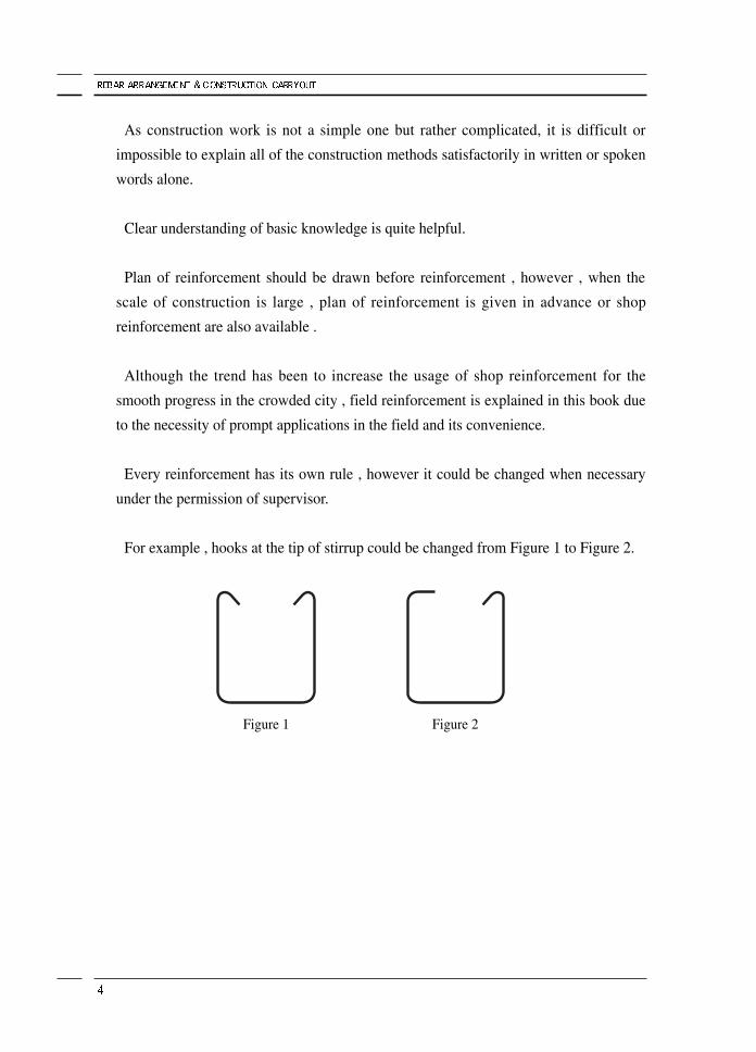
Every reinforcement has its own rule , however it could be changed when necessary
under the permission of supervisor.
For example , hooks at the tip of stirrup could be changed from Figure 1 to Figure 2.
Figure 1 Figure 2
2)What is drawing?Drawings are used in every industrial field with the development of industries.
Although their types and applications are different, there are agreed rules that are
called IPC(International Graphic Code), accepted by everyone in each field.
Specified rules and standards with reference to symbols, numbers, lines and letters are
adapted to drawings to help everyone understand what they mean.
When one begins to construct a building, one should carefully consider the
implications of drawings.
In this book, plan of reinforcement is briefed to help the workers understand them
more easily.
Drawings of construction work are grouped roughly as civil engineering and
architecture.
Although there are some differences, all the contents could be understood since they
are all in accordance with IPC mentioned above.
3) Classification of drawing
① Shop Drawing
Drawings that suggest overall dimensions of each member with symbols, numbers
and lines for the construction work
② Detailed Drawing
Detailed drawings that describe shapes , types and dimensions of each element for
the bar-fabrication
③ Understanding of Drawing
Drawings are in their own sequence beginning with the title and contents on the 1st
page.
Structure drawing of Rebar is for this case.
There are several types of drawings which include machinery, electricity,
sanitation, fire protection, communication, etc according to the type of work and
there are details as follows.
A) Construction
i. Building layout
ii. Elevation
iii. Plane figure
iv. Cross Section
v. Part Detailed drawing
B) Structure
i. Drawing of column center
ii. Plane figure of structure
iii. Drawing of stairway and slab rebar arrangement
iv. List of pillar , beam and retaining walls
v. Detailed drawing of rahmen rebar arrangement
C) In general, the order of drawing is in a sequence mentioned above, and all the
drawings are in scale.
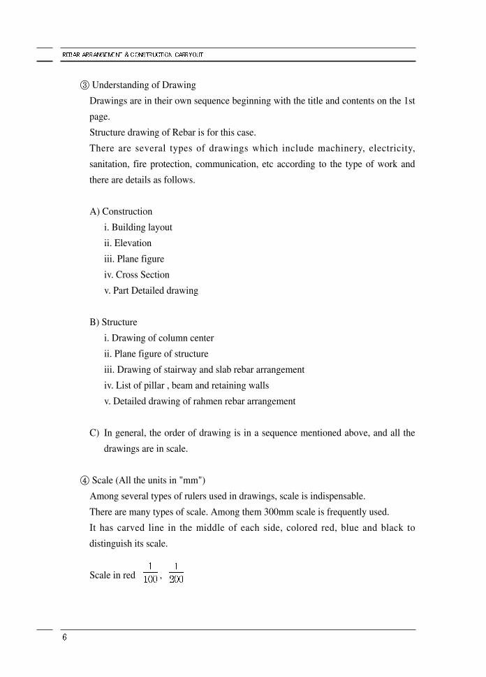
④ Scale (All the units in "mm")
Among several types of rulers used in drawings, scale is indispensable.
There are many types of scale. Among them 300mm scale is frequently used.
It has carved line in the middle of each side, colored red, blue and black to
distinguish its scale.
Scale in red ,
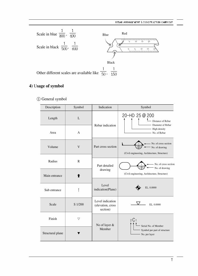
Scale in blue ,
Scale in black ,
Other different scales are available like ,
4) Usage of symbol
① General symbol
Description
Length
Area
Volume
Radius
Main entrance
Sub entrance
Scale
Finish
Structural plane
Indication
Rebar indication
Part cross section
Part detaileddrawing
Levelindication(Plane)
Level indication(elevation, cross
section)
No of layer &Member
SymbolSymbol
L
A
V
R
S 1/200
▽
▼
Distance of Rebar
Diameter of Rebar
High density
No. of Rebar
No. of cross section
No. of drawing
No. of cross section
No. of drawing
Serial No. of Member
Symbol per part of structure
No. per layer
EL. 0.0000
EL. 0.0000
(Civil engineering, Architecture, Structure)
(Civil engineering, Architecture, Structure)
RedBlue
Black
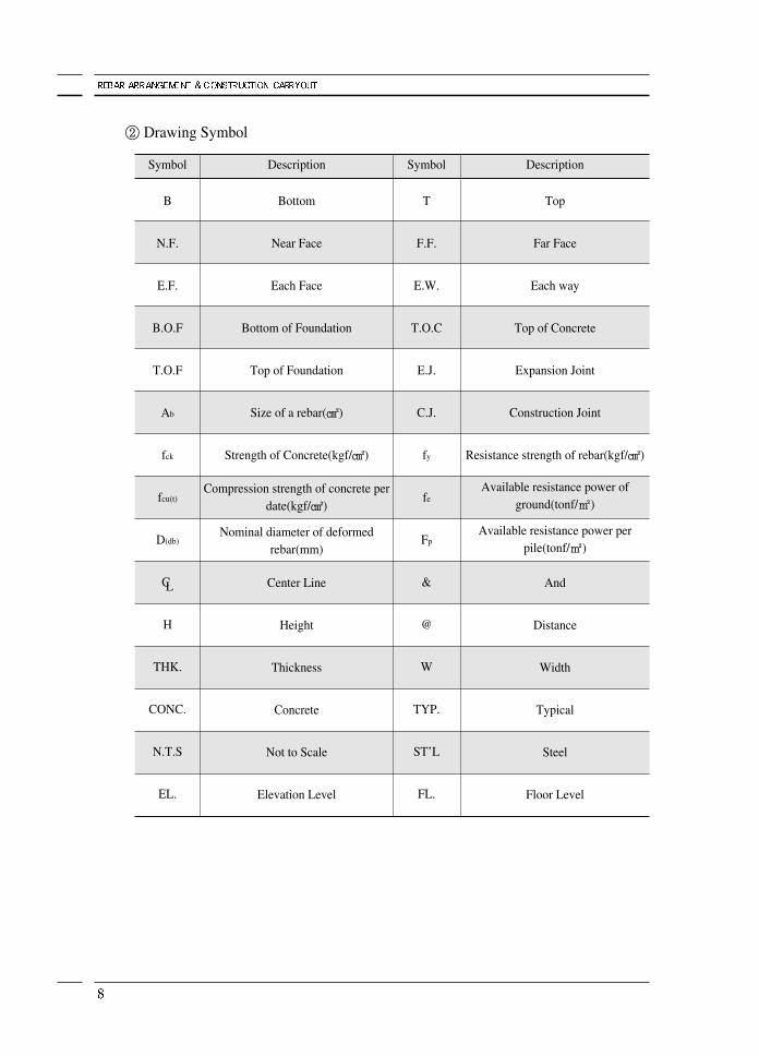
② Drawing Symbol
Symbol
B
N.F.
E.F.
B.O.F
T.O.F
Ab
fck
fcu(t)
D(db)
CL
H
THK.
CONC.
N.T.S
EL.
Description
Bottom
Near Face
Each Face
Bottom of Foundation
Top of Foundation
Size of a rebar(㎠)
Strength of Concrete(kgf/㎠)
Compression strength of concrete per date(kgf/㎠)
Nominal diameter of deformed rebar(mm)
Center Line
Height
Thickness
Concrete
Not to Scale
Elevation Level
Symbol
T
F.F.
E.W.
T.O.C
E.J.
C.J.
fy
fe
Fp
&
@
W
TYP.
ST’L
FL.
Description
Top
Far Face
Each way
Top of Concrete
Expansion Joint
Construction Joint
Resistance strength of rebar(kgf/㎠)
Available resistance power of ground(tonf/㎡)
Available resistance power per pile(tonf/㎡)
And
Distance
Width
Typical
Steel
Floor Level
2. Characteristic of Rebar
Throughout the reinforcement work, reinforcing bar strongly bonds to mixed concrete
and this makes floor, wall and other members very strong.
In other words, reinforcement is a bar that is embedded in the mixed concrete to make
a member strong.
Bar and concrete have low thermal expansion coefficients, 1×10⁻⁵ , and therefore
have little thermal deformation or failure, cooperatively strengthening members.
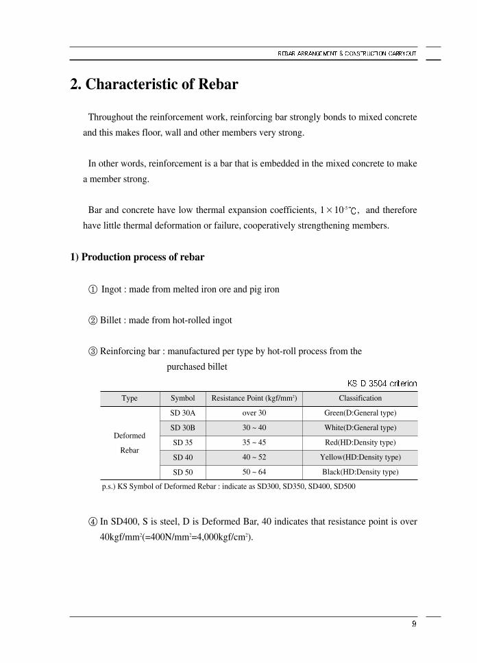
1) Production process of rebar
① Ingot : made from melted iron ore and pig iron
② Billet : made from hot-rolled ingot
③ Reinforcing bar : manufactured per type by hot-roll process from the
purchased billet
④ In SD400, S is steel, D is Deformed Bar, 40 indicates that resistance point is over
40kgf/mm2(=400N/mm2=4,000kgf/cm2).
Type
Deformed
Rebar
Symbol
SD 30A
SD 30B
SD 35
SD 40
SD 50
Classification
Green(D:General type)
White(D:General type)
Red(HD:Density type)
Yellow(HD:Density type)
Black(HD:Density type)
p.s.) KS Symbol of Deformed Rebar : indicate as SD300, SD350, SD400, SD500
Resistance Point (kgf/mm2)
over 30
30 ~ 40
35 ~ 45
40 ~ 52
50 ~ 64
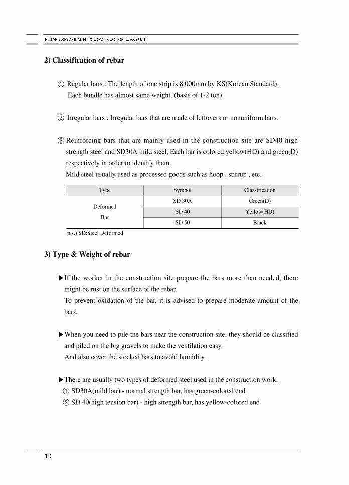
2) Classification of rebar
① Regular bars : The length of one strip is 8,000mm by KS(Korean Standard).
Each bundle has almost same weight. (basis of 1-2 ton)
② Irregular bars : Irregular bars that are made of leftovers or nonuniform bars.
③ Reinforcing bars that are mainly used in the construction site are SD40 high
strength steel and SD30A mild steel, Each bar is colored yellow(HD) and green(D)
respectively in order to identify them.
Mild steel usually used as processed goods such as hoop , stirrup , etc.
3) Type & Weight of rebar
▶If the worker in the construction site prepare the bars more than needed, there
might be rust on the surface of the rebar.
To prevent oxidation of the bar, it is advised to prepare moderate amount of the
bars.
▶When you need to pile the bars near the construction site, they should be classified
and piled on the big gravels to make the ventilation easy.
And also cover the stocked bars to avoid humidity.
▶There are usually two types of deformed steel used in the construction work.
① SD30A(mild bar) - normal strength bar, has green-colored end
② SD 40(high tension bar) - high strength bar, has yellow-colored end
Type
Deformed
Bar
Symbol
SD 30A
SD 40
SD 50
Classification
Green(D)
Yellow(HD)
Black
p.s.) SD:Steel Deformed
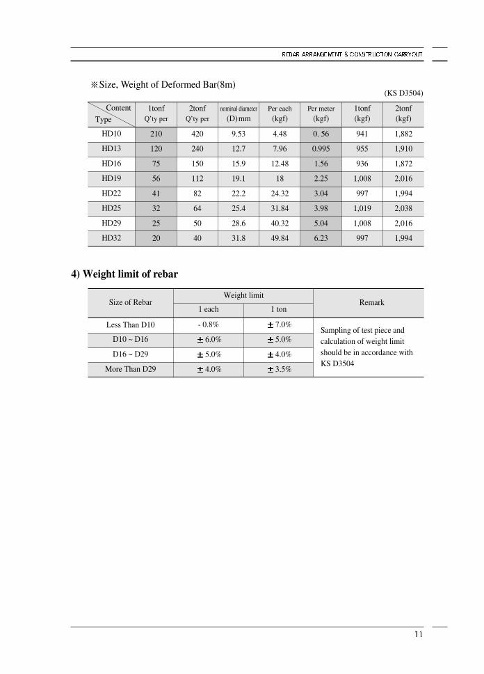
※Size, Weight of Deformed Bar(8m)
4) Weight limit of rebar
HD10
HD13
HD16
HD19
HD22
HD25
HD29
HD32
Content
Type1tonf
Q’ty per
210
120
75
56
41
32
25
20
2tonfQ’ty per
420
240
150
112
82
64
50
40
nominal diameter(D)mm
9.53
12.7
15.9
19.1
22.2
25.4
28.6
31.8
Per each(kgf)
4.48
7.96
12.48
18
24.32
31.84
40.32
49.84
Per meter(kgf)
0. 56
0.995
1.56
2.25
3.04
3.98
5.04
6.23
1tonf(kgf)
941
955
936
1,008
997
1,019
1,008
997
2tonf(kgf)
1,882
1,910
1,872
2,016
1,994
2,038
2,016
1,994
Size of Rebar
Less Than D10
D10 ~ D16
D16 ~ D29
More Than D29
1 each
- 0.8%
6.0%
5.0%
4.0%
Weight limit
1 ton
7.0%
5.0%
4.0%
3.5%
Remark
Sampling of test piece andcalculation of weight limitshould be in accordance withKS D3504
(KS D3504)
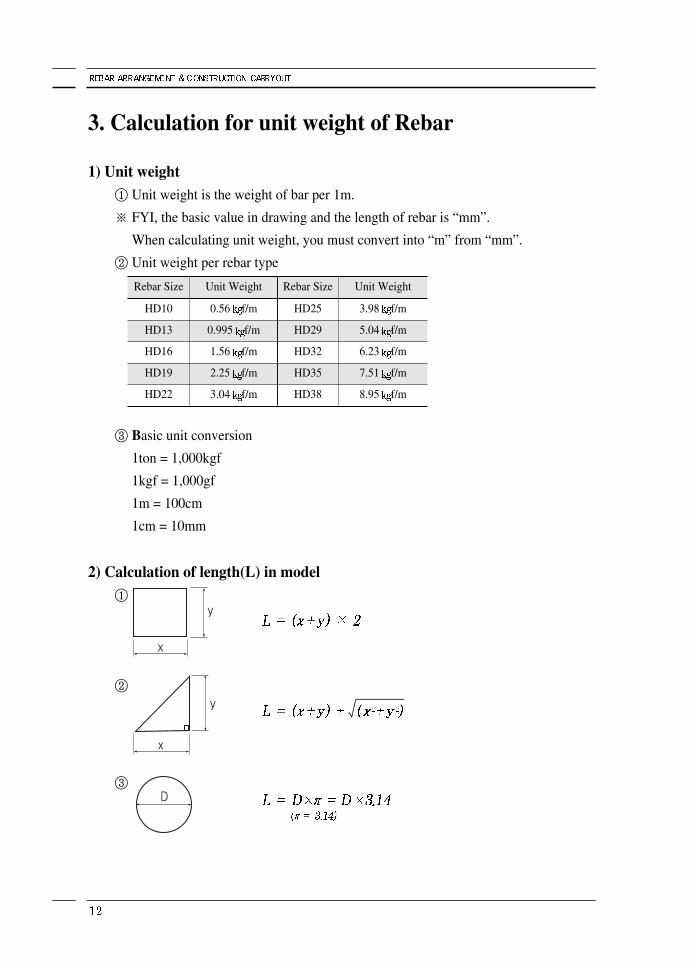
3. Calculation for unit weight of Rebar
1) Unit weight① Unit weight is the weight of bar per 1m.
※ FYI, the basic value in drawing and the length of rebar is “mm”.
When calculating unit weight, you must convert into “m” from “mm”.
② Unit weight per rebar type
③ Basic unit conversion
1ton = 1,000kgf
1kgf = 1,000gf
1m = 100cm
1cm = 10mm
2) Calculation of length(L) in model①
②
③
Rebar Size
HD10
HD13
HD16
HD19
HD22
Unit Weight
0.56 f/m
0.995 f/m
1.56 f/m
2.25 f/m
3.04 f/m
Rebar Size
HD25
HD29
HD32
HD35
HD38
Unit Weight
3.98 f/m
5.04 f/m
6.23 f/m
7.51 f/m
8.95 f/m
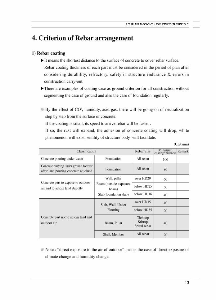
4. Criterion of Rebar arrangement
1) Rebar coating▶It means the shortest distance to the surface of concrete to cover rebar surface.
Rebar coating thickness of each part must be considered in the period of plan after
considering durability, refractory, safety in structure endurance & errors in
construction carry-out.
▶There are examples of coating case as ground criterion for all construction without
segmenting the case of ground and also the case of foundation regularly.
※ By the effect of CO2, humidity, acid gas, there will be going on of neutralization
step by step from the surface of concrete.
If the coating is small, its speed to arrive rebar will be faster .
If so, the rust will expand, the adhesion of concrete coating will drop, white
phenomenon will exist, senility of structure body will facilitate.
※ Note : “direct exposure to the air of outdoor” means the case of direct exposure of
climate change and humidity change.
Concrete pouring under water
Concrete burying under ground foreverafter land pouring concrete adjoined
Concrete part to expose to outdoor
air and to adjoin land directly
Concrete part not to adjoin land and
outdoor air
Foundation
Foundation
Wall, pillar
Beam (outside exposure
beam)
Slab(foundation slab)
Slab, Wall, Under Flooring
Beam, Pillar
Shell, Member
Minimumcoating/thickness
100
80
60
50
40
40
20
40
20
RemarkRebar Size
All rebar
All rebar
over HD29
below HD25
below HD16
over HD35
below HD35
TiehoopStirrup
Spiral rebar
All rebar
Classification
(Unit:mm)
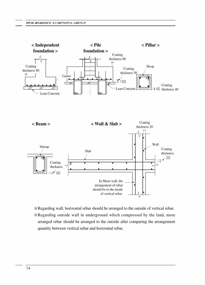
※Regarding wall, horizontal rebar should be arranged to the outside of vertical rebar.
※Regarding outside wall in underground which compressed by the land, more
arranged rebar should be arranged to the outside after comparing the arrangement
quantity between vertical rebar and horizontal rebar.
< Independentfoundation >
< Beam > < Wall & Slab >
< Pilefoundation >
< Pillar >
Coatingthickness 80
Coatingthickness 80
Coatingthickness 40
Coatingthickness 20
In Shear wall, thearrangement of rebar
should be to the insideof vertical rebar.
Wall
Coatingthickness
Coatingthickness 50
Hoop
Lean Concrete
StirrupSlab
Lean Concrete
Cushion
Coatingthickness
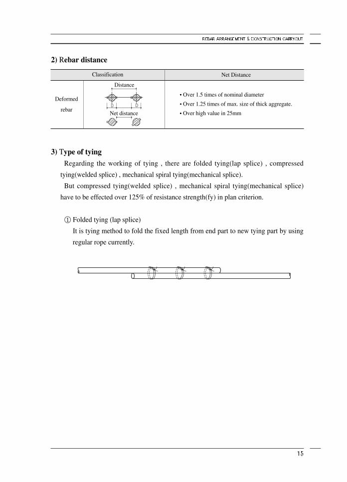
2) Rebar distance
3) Type of tyingRegarding the working of tying , there are folded tying(lap splice) , compressed
tying(welded splice) , mechanical spiral tying(mechanical splice).
But compressed tying(welded splice) , mechanical spiral tying(mechanical splice)
have to be effected over 125% of resistance strength(fy) in plan criterion.
① Folded tying (lap splice)
It is tying method to fold the fixed length from end part to new tying part by using
regular rope currently.
Deformed
rebar
Net Distance
Over 1.5 times of nominal diameter
Over 1.25 times of max. size of thick aggregate.
Over high value in 25mm
Classification
Distance
Net distance
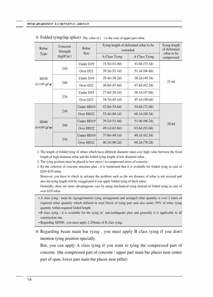
※ Folded tying(lap splice)
※ Regarding beam main bar tying , you must apply B class tying if you don't
mention tying position specially.
But, you can apply A class tying if you want to tying the compressed part of
concrete. (the compressed part of concrete : upper part main bar places near center
part of span, lower part main bar places near pillar)
ConcreteStrength
(kgf/Cm2)
210
240
270
210
240
270
21.6d
28.8d
RebarSize
Under D19
Over D22
Under D19
Over D22
Under D19
Over D22
Under HD19
Over HD22
Under HD19
Over HD22
Under HD19
Over HD22
31.5d (41.0d)
39.3d (51.1d)
29.4d (38.2d)
36.8d (47.8d)
27.8d (36.1d)
34.7d (45.1d)
42.0d (54.6d)
52.4d (68.1d)
39.2d (51.0d)
49.1d (63.8d)
37.0d (48.1d)
46.3d (60.2d)
41.0d (53.3d)
51.1d (66.4d)
38.2d (49.7d)
47.8d (62.2d)
36.1d (47.0d)
45.1d (58.6d)
54.6d (71.0d)
68.1d (88.5d)
51.0d (66.2d)
63.8d (83.0d)
48.1d (62.5d)
60.2d (78.2d)
1. The length of folded tying of rebars which have different diameter must over high value between the fixed
length of high diameter rebar and the folded tying length of low diameter rebar .
2. The tying position must be placed to low stress / to compressed stress of concrete.
3. By the criterion of concrete structure plan , it is mentioned that it is available for folded tying in case of
D29~D35 rebar.
However, you have to check in advance the problem such as the net distance of rebar is not secured and
also the tying length will be exaggerated if you apply folded tying of thick rebar.
Generally, there are more advantageous case by using mechanical tying instead of folded tying in case of
over D29 rebar.
A class tying : must be zigzag(rotation) tying arrangement and arranged rebar quantity is over 2 times of
required rebar quantity which defined in total block of tying part and also under 50% of rebar tying
quantity within required folded length.
B class tying : it is available for the tying of anti-earthquake plan and generally it is applicable to all
construction site.
Regarding SD500 , you must apply 1.25times of B class tying.
The value in ( ) is the case of upper part rebar.
Tying length of deformed rebar to beextended
Tying lengthof deformedrebar to becompressedA Class TyingA Class Tying
Rebar
Type
SD30
(fy=3,000 )
SD40
(fy=4,000 )
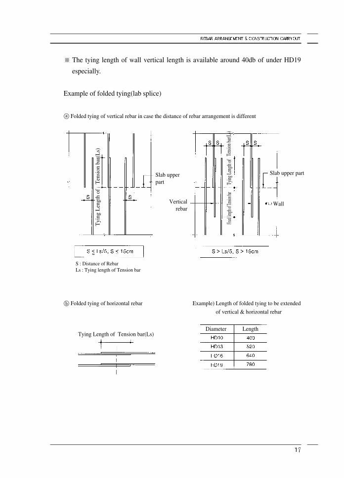
※ The tying length of wall vertical length is available around 40db of under HD19
especially.
Example of folded tying(lab splice)
ⓐ Folded tying of vertical rebar in case the distance of rebar arrangement is different
ⓑ Folded tying of horizontal rebar Example) Length of folded tying to be extended
of vertical & horizontal rebar
Slab upperpart
Verticalrebar
Slab upper part
Tyi
ng L
engt
h of
Tying Length of Tension bar(Ls)Diameter Length
S : Distance of RebarLs : Tying length of Tension bar
Tying
Len
gth of
Fix
ed len
gth of
Tensio
n bar
Ten
sion
bar
(Ls)
Wall
Tens
ion ba
r(Ls)
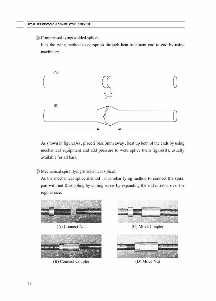
② Compressed tying(welded splice)
It is the tying method to compress through heat-treatment end to end by using
machinery.
As shown in figure(A) , place 2 bars 3mm away , heat up both of the ends by using
mechanical equipment and add pressure to weld splice them figure(B), usually
available for all bars.
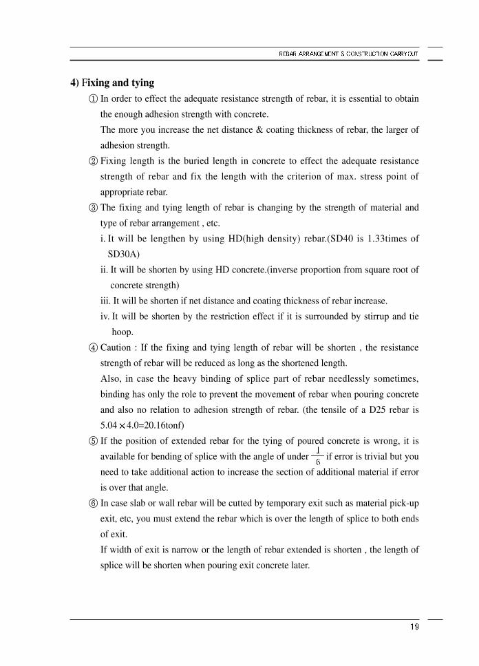
③ Mechanical spiral tying(mechanical splice).
As the mechanical splice method , it is rebar tying method to connect the spiral
part with nut & coupling by cutting screw by expanding the end of rebar over the
regular size.
(A) Connect Nut
(B) Connect Coupler
(C) Move Coupler
(D) Move Nut
4) Fixing and tying① In order to effect the adequate resistance strength of rebar, it is essential to obtain
the enough adhesion strength with concrete.
The more you increase the net distance & coating thickness of rebar, the larger of
adhesion strength.
② Fixing length is the buried length in concrete to effect the adequate resistance
strength of rebar and fix the length with the criterion of max. stress point of
appropriate rebar.
③ The fixing and tying length of rebar is changing by the strength of material and
type of rebar arrangement , etc.
i. It will be lengthen by using HD(high density) rebar.(SD40 is 1.33times of
SD30A)
ii. It will be shorten by using HD concrete.(inverse proportion from square root of
concrete strength)
iii. It will be shorten if net distance and coating thickness of rebar increase.
iv. It will be shorten by the restriction effect if it is surrounded by stirrup and tie
hoop.
④ Caution : If the fixing and tying length of rebar will be shorten , the resistance
strength of rebar will be reduced as long as the shortened length.
Also, in case the heavy binding of splice part of rebar needlessly sometimes,
binding has only the role to prevent the movement of rebar when pouring concrete
and also no relation to adhesion strength of rebar. (the tensile of a D25 rebar is
5.04 4.0=20.16tonf)
⑤ If the position of extended rebar for the tying of poured concrete is wrong, it is
available for bending of splice with the angle of under if error is trivial but you
need to take additional action to increase the section of additional material if error
is over that angle.
⑥ In case slab or wall rebar will be cutted by temporary exit such as material pick-up
exit, etc, you must extend the rebar which is over the length of splice to both ends
of exit.
If width of exit is narrow or the length of rebar extended is shorten , the length of
splice will be shorten when pouring exit concrete later.
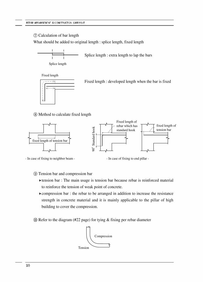
⑦ Calculation of bar length
What should be added to original length : splice length, fixed length
Splice length : extra length to lap the bars
Fixed length : developed length when the bar is fixed
⑧ Method to calculate fixed length
⑨ Tension bar and compression bar
tension bar : The main usage is tension bar because rebar is reinforced material
to reinforce the tension of weak point of concrete.
compression bar : the rebar to be arranged in addition to increase the resistance
strength in concrete material and it is mainly applicable to the pillar of high
building to cover the compression.
⑩ Refer to the diagram (#22 page) for tying & fixing per rebar diameter
Splice length
Fixed length
- In case of fixing to neighbor beam -
Compression
Tension
fixed length oftension bar
Fixed length ofrebar which hasstandard hook
- In case of fixing to end pillar -
fixed length of tension bar
90°
Stan
dard
hoo
k
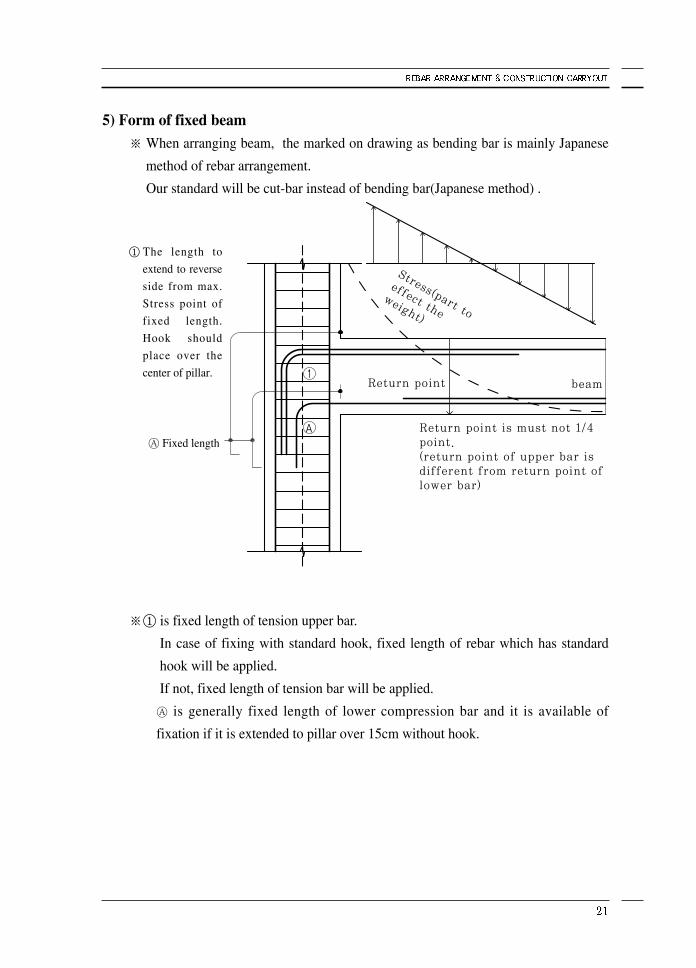
5) Form of fixed beam※ When arranging beam, the marked on drawing as bending bar is mainly Japanese
method of rebar arrangement.
Our standard will be cut-bar instead of bending bar(Japanese method) .
① The length to
extend to reverse
side from max.
Stress point of
fixed length.
Hook should
place over the
center of pillar.
※① is fixed length of tension upper bar.
In case of fixing with standard hook, fixed length of rebar which has standard
hook will be applied.
If not, fixed length of tension bar will be applied.
is generally fixed length of lower compression bar and it is available of
fixation if it is extended to pillar over 15cm without hook.
Fixed length
Stress(part to
effect theweight)
Return point beam
Return point is must not 1/4point. (return point of upper bar isdifferent from return point oflower bar)
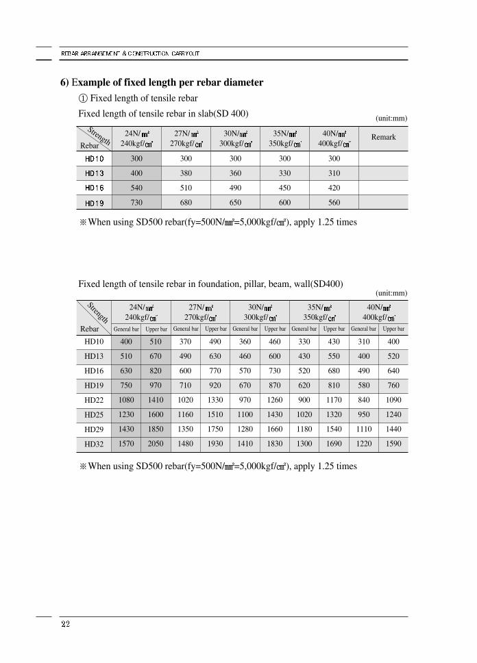
6) Example of fixed length per rebar diameter① Fixed length of tensile rebar
Fixed length of tensile rebar in slab(SD 400)
※When using SD500 rebar(fy=500N/㎟=5,000kgf/㎠), apply 1.25 times
Fixed length of tensile rebar in foundation, pillar, beam, wall(SD400)
※When using SD500 rebar(fy=500N/㎟=5,000kgf/㎠), apply 1.25 times
HD10
HD13
HD16
HD19
HD22
HD25
HD29
HD32
StrengthRebar
24N/240kgf/
27N/270kgf/
30N/300kgf/
35N/350kgf/
40N/400kgf/
400
510
630
750
1080
1230
1430
1570
510
670
820
970
1410
1600
1850
2050
24N/240kgf/
300
400
540
730
27N/270kgf/
300
380
510
680
30N/300kgf/
300
360
490
650
35N/350kgf/
300
330
450
600
40N/400kgf/
300
310
420
560
Remark
370
490
600
710
1020
1160
1350
1480
490
630
770
920
1330
1510
1750
1930
360
460
570
670
970
1100
1280
1410
460
600
730
870
1260
1430
1660
1830
330
430
520
620
900
1020
1180
1300
430
550
680
810
1170
1320
1540
1690
310
400
490
580
840
950
1110
1220
400
520
640
760
1090
1240
1440
1590
General bar Upper barGeneral bar Upper barGeneral bar Upper barGeneral bar Upper barGeneral bar Upper bar
(unit:mm)
(unit:mm)
StrengthRebar
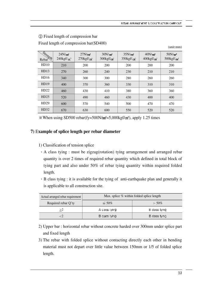
② Fixed length of compression bar
Fixed length of compression bar(SD400)
※When using SD500 rebar(fy=500N/㎟=5,000kgf/㎠), apply 1.25 times
7) Example of splice length per rebar diameter
1) Classification of tension splice
ㆍA class tying : must be zigzag(rotation) tying arrangement and arranged rebar
quantity is over 2 times of required rebar quantity which defined in total block of
tying part and also under 50% of rebar tying quantity within required folded
length.
ㆍB class tying : it is available for the tying of anti-earthquake plan and generally it
is applicable to all construction site.
2) Upper bar : horizontal rebar without concrete harded over 300mm under splice part
and fixed length
3) The rebar with folded splice without contacting directly each other in bending
material must not depart over little value between 150mm or 1/5 of folded splice
length.
HD10
HD13
HD16
HD19
HD22
HD25
HD29
HD32
24N/240kgf/
210
270
340
400
460
520
600
670
27N/270kgf/
200
260
300
370
430
490
570
630
30N/300kgf/
200
240
300
360
410
460
540
600
35N/350kgf/
200
230
280
330
380
430
500
550
40N/400kgf/
200
210
260
310
360
400
470
520
50N/500kgf/
200
210
260
310
360
400
470
520
2
2
50% 50%
Actual arranged rebar requirement
Required rebar Q’ty
Max. splice % within folded splice length
(unit:mm)StrengthRebar
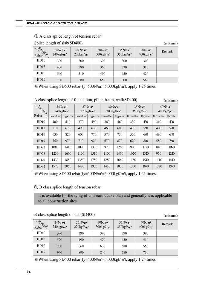
① A class splice length of tension rebar
Splice length of slab(SD400)
※When using SD500 rebar(fy=500N/㎟=5,000kgf/㎠), apply 1.25 times
A class splice length of foundation, pillar, beam, wall(SD400)
※When using SD500 rebar(fy=500N/㎟=5,000kgf/㎠), apply 1.25 times
② B class splice length of tension rebar
It is available for the tying of anti-earthquake plan and generally it is applicableto all construction sites.
B class splice length of slab(SD400)
※When using SD500 rebar(fy=500N/㎟=5,000kgf/㎠), apply 1.25 times
HD10
HD13
HD16
HD19
HD22
HD25
HD29
HD32
Rebar
24N/240kgf/
27N/270kgf/
30N/300kgf/
35N/350kgf/
40N/400kgf/
400
510
630
750
1080
1230
1430
1570
510
670
820
970
1410
1600
1850
2050
HD10
HD13
HD16
HD19
Rebar
24N/240kgf/
390
520
700
940
27N/270kgf/
390
490
660
890
30N/300kgf/
390
470
630
840
35N/350kgf/
390
430
580
780
40N/400kgf/
390
410
550
730
Remark
370
490
600
710
1020
1160
1350
1480
490
630
770
920
1330
1510
1750
1930
360
460
570
670
970
1100
1280
1410
460
600
730
870
1260
1430
1660
1830
330
430
520
620
900
1020
1180
1300
430
550
680
810
1170
1320
1540
1690
310
400
490
580
840
950
1110
1220
400
520
640
760
1090
1240
1440
1590
General bar Upper barGeneral bar Upper barGeneral bar Upper barGeneral bar Upper barGeneral bar Upper bar
HD10
HD13
HD16
HD19
Rebar
24N/240kgf/
300
400
540
730
27N/270kgf/
300
380
510
680
30N/300kgf/
300
360
490
650
35N/350kgf/
300
330
450
600
40N/400kgf/
300
310
420
560
Remark
(unit:mm)
(unit:mm)
(unit:mm)
Strength
Strength
Strength
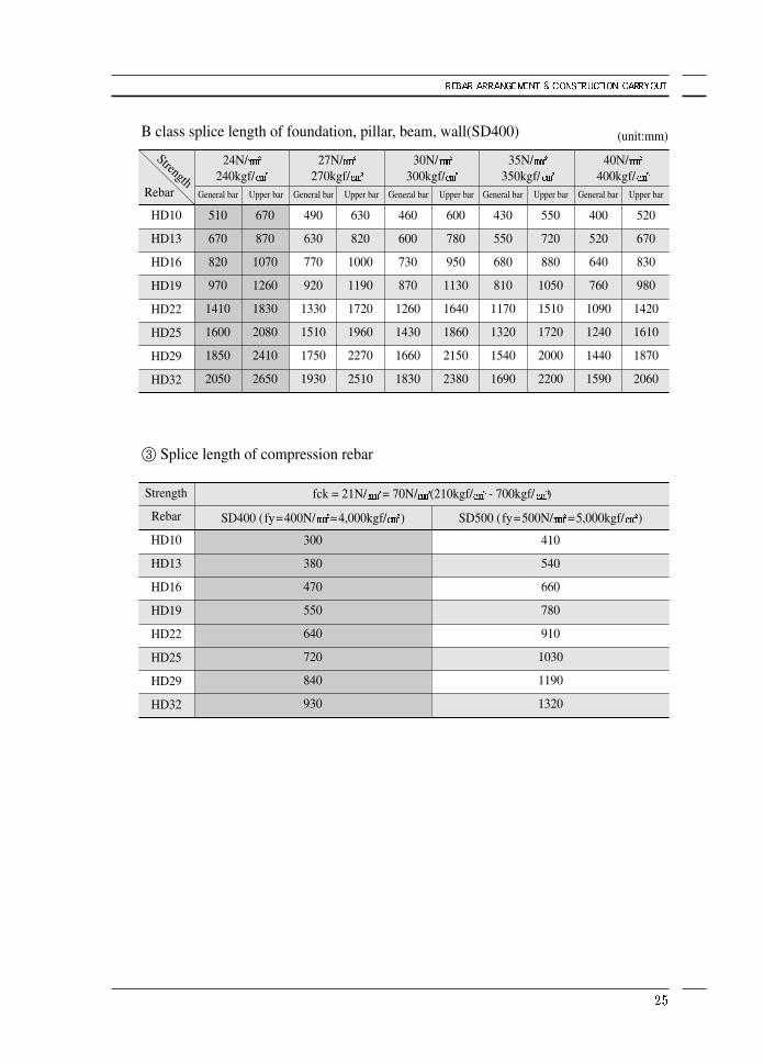
B class splice length of foundation, pillar, beam, wall(SD400)
※When using SD500 rebar(fy=500N/㎟=5,000kgf/㎠), apply 1.25 times
③ Splice length of compression rebar
HD10
HD13
HD16
HD19
HD22
HD25
HD29
HD32
Rebar
24N/240kgf/
27N/270kgf/
30N/300kgf/
35N/350kgf/
40N/400kgf/
510
670
820
970
1410
1600
1850
2050
670
870
1070
1260
1830
2080
2410
2650
490
630
770
920
1330
1510
1750
1930
630
820
1000
1190
1720
1960
2270
2510
460
600
730
870
1260
1430
1660
1830
600
780
950
1130
1640
1860
2150
2380
430
550
680
810
1170
1320
1540
1690
550
720
880
1050
1510
1720
2000
2200
400
520
640
760
1090
1240
1440
1590
520
670
830
980
1420
1610
1870
2060
General bar Upper barGeneral bar Upper barGeneral bar Upper barGeneral bar Upper barGeneral bar Upper bar
HD10
HD13
HD16
HD19
HD22
HD25
HD29
HD32
Strength
Rebar
fck = 21N/ = 70N/ (210kgf/ - 700kgf/ )
SD400 (fy=400N/ =4,000kgf/ ) SD500 (fy=500N/ =5,000kgf/ )
300
380
470
550
640
720
840
930
410
540
660
780
910
1030
1190
1320
(unit:mm)
Strength
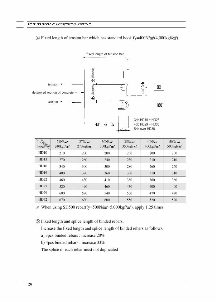
④ Fixed length of tension bar which has standard hook fy=400N/㎟(4,000kgf/㎠)
※ When using SD500 rebar(fy=500N/㎟=5,000kgf/㎠), apply 1.25 times.
⑤ Fixed length and splice length of binded rebars.
Increase the fixed length and splice length of binded rebars as follows.
a) 3pcs binded rebars : increase 20%
b) 4pcs binded rebars : increase 33%
The splice of each rebar must not duplicated
HD10
HD13
HD16
HD19
HD22
HD25
HD29
HD32
Rebar
24N/240kgf/
210
270
340
400
460
520
600
670
27N/270kgf/
200
260
300
370
430
490
570
630
30N/300kgf/
200
240
300
360
410
460
540
600
35N/350kgf/
200
230
280
330
380
430
500
550
40N/400kgf/
200
210
260
310
360
400
470
520
50N/500kgf/
200
210
260
310
360
400
470
520
fixed length of tension bar
tension
or3db HD10 ~ HD254db HD29 ~ HD355db over HD38
min
(diam
eter)
(diam
eter)
destroyed section of concrete
Strength
tension
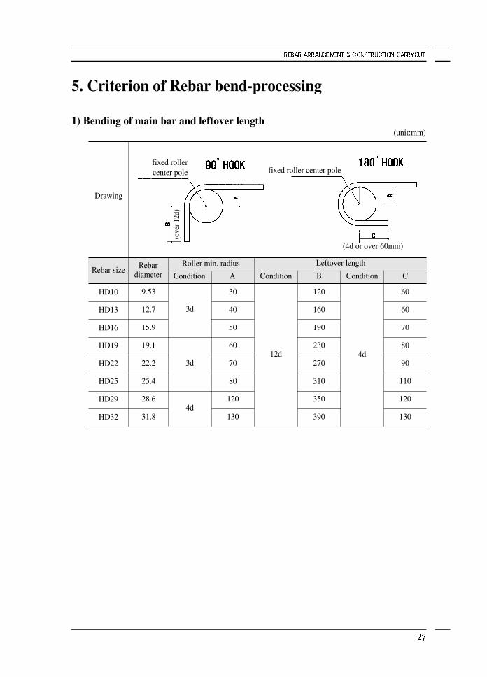
5. Criterion of Rebar bend-processing
1) Bending of main bar and leftover length
3d
3d
4d
30
40
50
60
70
80
120
130
12d
120
160
190
230
270
310
350
390
4d
60
60
70
80
90
110
120
130
Rebar size
HD10
HD13
HD16
HD19
HD22
HD25
HD29
HD32
Drawing
Leftover lengthRoller min. radius
Condition A Condition B Condition C
9.53
12.7
15.9
19.1
22.2
25.4
28.6
31.8
Rebardiameter
(unit:mm)
fixed roller center pole fixed roller center pole
(4d or over 60mm)
(ove
r 12d
)
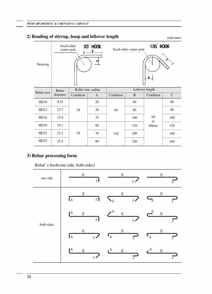
2) Bending of stirrup, hoop and leftover length
3) Rebar processing form
Rebar’s hook(one-side, both-sides)
one-side
both-sides
2d
3d
20
30
35
60
70
80
9.53
12.7
15.9
19.1
22.2
25.4
6d
12d
60
80
100
120
280
320
6dor
60mm
60
80
100
120
140
160
Rebar size
HD10
HD13
HD16
HD19
HD22
HD25
Rebardiameter
Drawing
Leftover lengthRoller min. radius
Condition A Condition B Condition C
(unit:mm)
fixed roller center pole fixed roller center pole
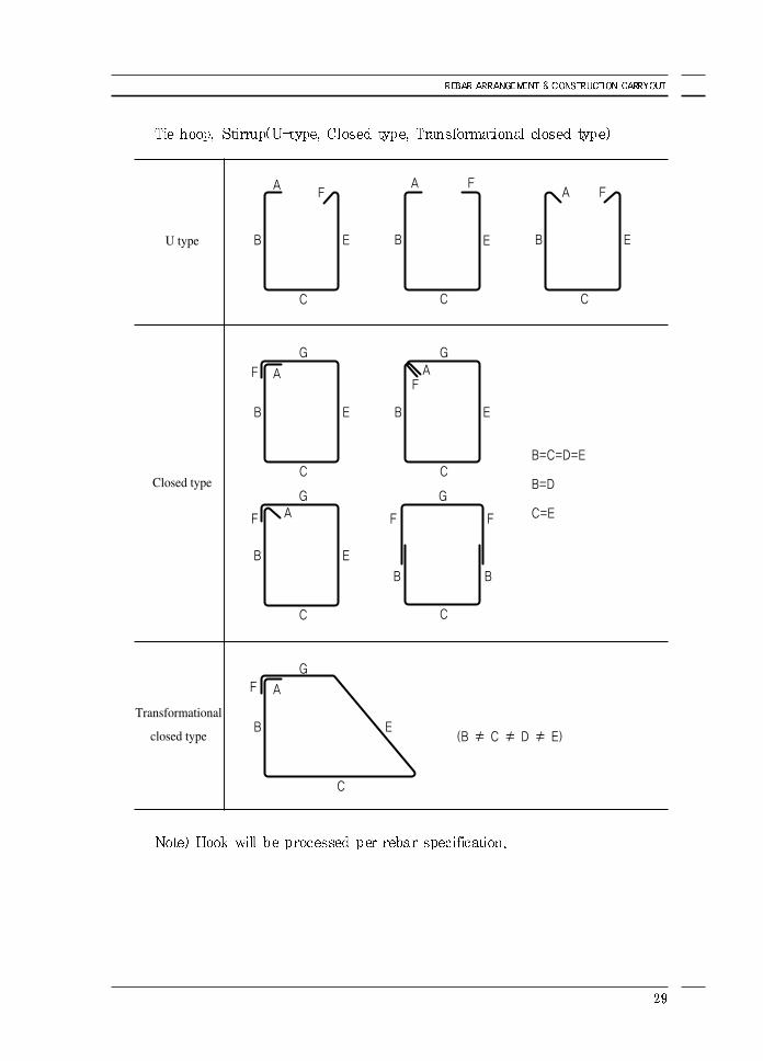
U type
Closed type
Transformational
closed type
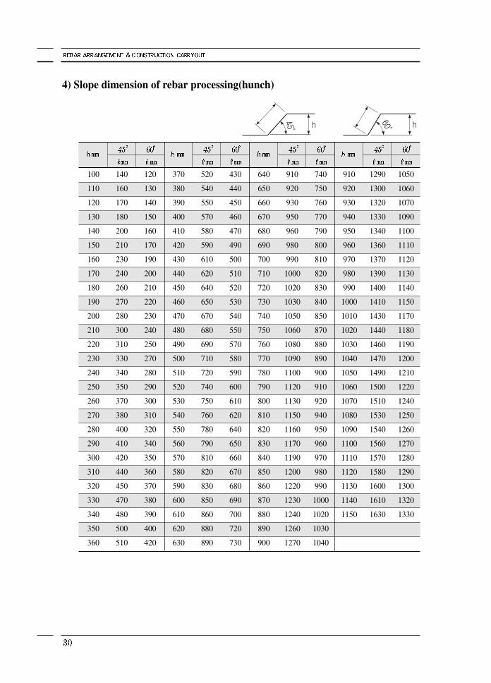
4) Slope dimension of rebar processing(hunch)
100
110
120
130
140
150
160
170
180
190
200
210
220
230
240
250
260
270
280
290
300
310
320
330
340
350
360
140
160
170
180
200
210
230
240
260
270
280
300
310
330
340
350
370
380
400
410
420
440
450
470
480
500
510
120
130
140
150
160
170
190
200
210
220
230
240
250
270
280
290
300
310
320
340
350
360
370
380
390
400
420
370
380
390
400
410
420
430
440
450
460
470
480
490
500
510
520
530
540
550
560
570
580
590
600
610
620
630
520
540
550
570
580
590
610
620
640
650
670
680
690
710
720
740
750
760
780
790
810
820
830
850
860
880
890
430
440
450
460
470
490
500
510
520
530
540
550
570
580
590
600
610
620
640
650
660
670
680
690
700
720
730
640
650
660
670
680
690
700
710
720
730
740
750
760
770
780
790
800
810
820
830
840
850
860
870
880
890
900
910
920
930
950
960
980
990
1000
1020
1030
1050
1060
1080
1090
1100
1120
1130
1150
1160
1170
1190
1200
1220
1230
1240
1260
1270
740
750
760
770
790
800
810
820
830
840
850
870
880
890
900
910
920
940
950
960
970
980
990
1000
1020
1030
1040
910
920
930
940
950
960
970
980
990
1000
1010
1020
1030
1040
1050
1060
1070
1080
1090
1100
1110
1120
1130
1140
1150
1290
1300
1320
1330
1340
1360
1370
1390
1400
1410
1430
1440
1460
1470
1490
1500
1510
1530
1540
1560
1570
1580
1600
1610
1630
1050
1060
1070
1090
1100
1110
1120
1130
1140
1150
1170
1180
1190
1200
1210
1220
1240
1250
1260
1270
1280
1290
1300
1320
1330
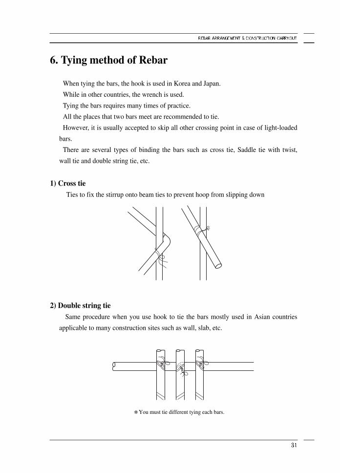
6. Tying method of Rebar
When tying the bars, the hook is used in Korea and Japan.
While in other countries, the wrench is used.
Tying the bars requires many times of practice.
All the places that two bars meet are recommended to tie.
However, it is usually accepted to skip all other crossing point in case of light-loaded
bars.
There are several types of binding the bars such as cross tie, Saddle tie with twist,
wall tie and double string tie, etc.
1) Cross tieTies to fix the stirrup onto beam ties to prevent hoop from slipping down
2) Double string tieSame procedure when you use hook to tie the bars mostly used in Asian countries
applicable to many construction sites such as wall, slab, etc.
You must tie different tying each bars.
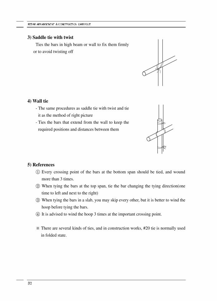
3) Saddle tie with twistTies the bars in high beam or wall to fix them firmly
or to avoid twisting off
4) Wall tie- The same procedures as saddle tie with twist and tie
it as the method of right picture
- Ties the bars that extend from the wall to keep the
required positions and distances between them
5) References① Every crossing point of the bars at the bottom span should be tied, and wound
more than 3 times.
② When tying the bars at the top span, tie the bar changing the tying direction(one
time to left and next to the right)
③ When tying the bars in a slab, you may skip every other, but it is better to wind the
hoop before tying the bars.
④ It is advised to wind the hoop 3 times at the important crossing point.
※ There are several kinds of ties, and in construction works, #20 tie is normally used
in folded state.
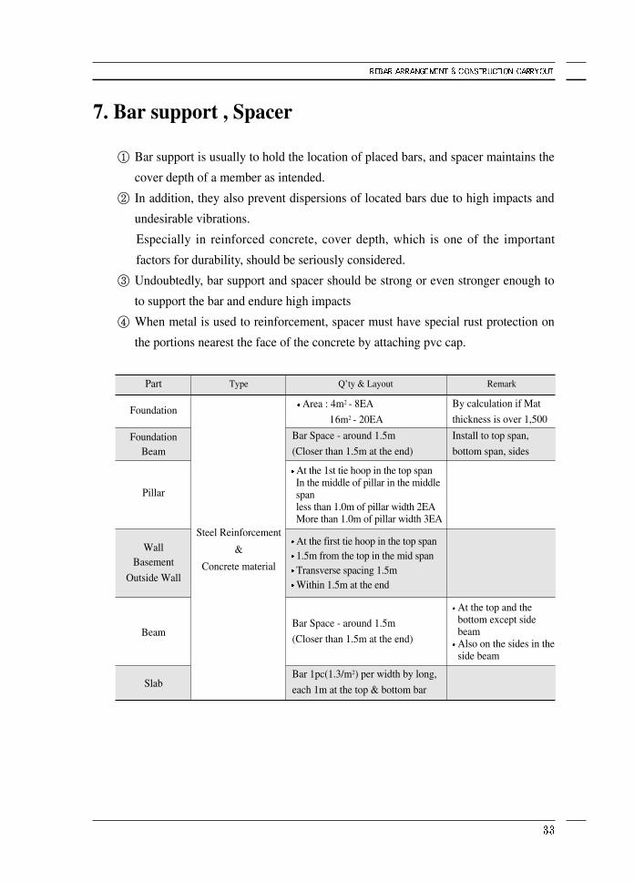
7. Bar support , Spacer
① Bar support is usually to hold the location of placed bars, and spacer maintains the
cover depth of a member as intended.
② In addition, they also prevent dispersions of located bars due to high impacts and
undesirable vibrations.
Especially in reinforced concrete, cover depth, which is one of the important
factors for durability, should be seriously considered.
③ Undoubtedly, bar support and spacer should be strong or even stronger enough to
to support the bar and endure high impacts
④ When metal is used to reinforcement, spacer must have special rust protection on
the portions nearest the face of the concrete by attaching pvc cap.
Area : 4m2 - 8EA
16m2 - 20EA
Bar Space - around 1.5m
(Closer than 1.5m at the end)
Install to top span,
bottom span, sides
By calculation if Mat
thickness is over 1,500
At the top and thebottom except sidebeamAlso on the sides in theside beam
At the 1st tie hoop in the top span In the middle of pillar in the middlespanless than 1.0m of pillar width 2EAMore than 1.0m of pillar width 3EA
At the first tie hoop in the top span1.5m from the top in the mid spanTransverse spacing 1.5mWithin 1.5m at the end
Bar Space - around 1.5m
(Closer than 1.5m at the end)
Bar 1pc(1.3/m2) per width by long,
each 1m at the top & bottom bar
RemarkQ’ty & LayoutType
Steel Reinforcement
&
Concrete material
Part
Foundation
Foundation Beam
Pillar
WallBasement
Outside Wall
Beam
Slab
8. Conventional processing work tools
Once the construction work is initiated, reinforcement needs to be manufactured,
several different tools are used depending on the type of work.
1) Types of conventional tools.① Bending die : die to bend the bar on
② Bender : bends the bars
③ Hammer : adds force to cut the bar
④ Lower cutting blade
⑤ Upper cutting blade
⑥ Mat plate to fix the cutbar
⑦ Various types of bar bender and bar cutter are available(see Chapter.3)
2) Preparation before reinforcement of rebar work① Fabricate the bar bending die (The height should be about 850mm).
② Prepare the power cable to connect the bending machine and binding machine
③ Prepare chalk or other writing instrument to mark the dimension.
④ Prepare the tools and bending die.

<Bending Table>
<Manual Bender> Prepare per rebar size
<Hammer>
<Manual Cutter>
<Mat> <Low cutting blade> <Upper cutting blade>
Bending PlateBending Pin
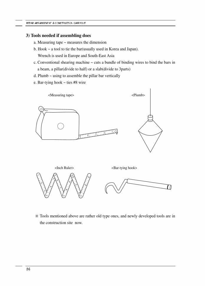
3) Tools needed if assembling doesa. Measuring tape ~ measures the dimension
b. Hook ~ a tool to tie the bar(usually used in Korea and Japan).
Wrench is used in Europe and South-East Asia
c. Conventional shearing machine ~ cuts a bundle of binding wires to bind the bars in
a beam, a pillar(divide to half) or a slab(divide to 3parts)
d. Plumb ~ using to assemble the pillar bar vertically
e. Bar-tying hook ~ ties #8 wire
※ Tools mentioned above are rather old type ones, and newly developed tools are in
the construction site now.
<Measuring tape>
<Inch Ruler> <Bar-tying hook>
<Plumb>
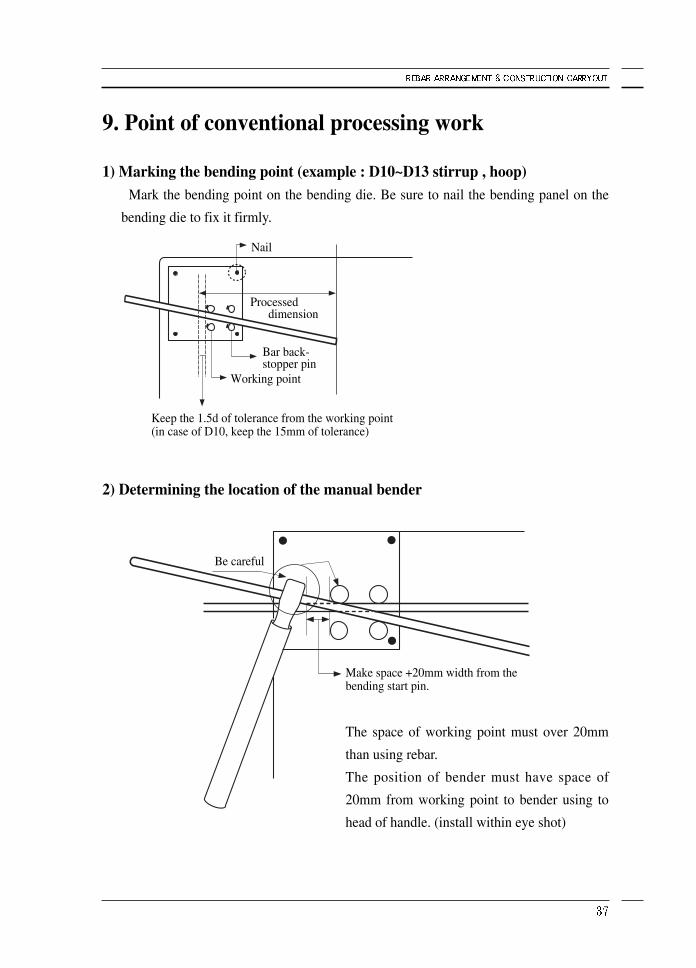
9. Point of conventional processing work
1) Marking the bending point (example : D10~D13 stirrup , hoop)Mark the bending point on the bending die. Be sure to nail the bending panel on the
bending die to fix it firmly.
2) Determining the location of the manual bender
Nail
Bar back-stopper pin
Working point
Be careful
Make space +20mm width from thebending start pin.
Keep the 1.5d of tolerance from the working point(in case of D10, keep the 15mm of tolerance)
Processed dimension
The space of working point must over 20mm
than using rebar.
The position of bender must have space of
20mm from working point to bender using to
head of handle. (install within eye shot)
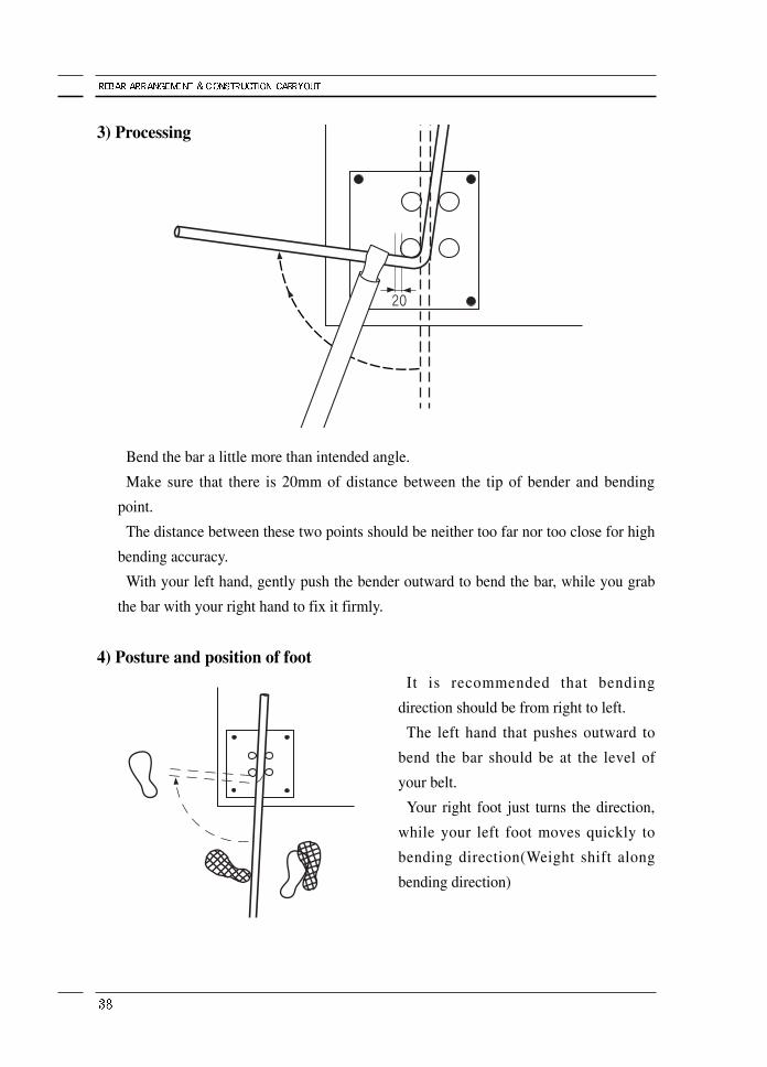
3) Processing
Bend the bar a little more than intended angle.
Make sure that there is 20mm of distance between the tip of bender and bending
point.
The distance between these two points should be neither too far nor too close for high
bending accuracy.
With your left hand, gently push the bender outward to bend the bar, while you grab
the bar with your right hand to fix it firmly.
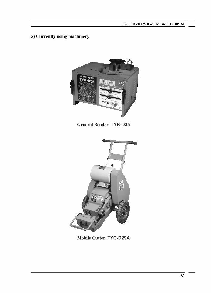
4) Posture and position of footIt is recommended that bending
direction should be from right to left.
The left hand that pushes outward to
bend the bar should be at the level of
your belt.
Your right foot just turns the direction,
while your left foot moves quickly to
bending direction(Weight shift along
bending direction)
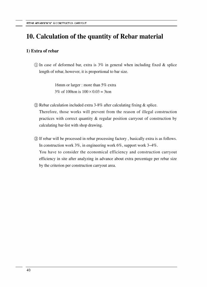
5) Currently using machinery
General Bender TYB-D35
Mobile Cutter TYC-D29A
10. Calculation of the quantity of Rebar material
1) Extra of rebar
① In case of deformed bar, extra is 3% in general when including fixed & splice
length of rebar, however, it is proportional to bar size.
16mm or larger : more than 5% extra
3% of 100ton is 100×0.03 = 3ton
② Rebar calculation included extra 3-8% after calculating fixing & splice.
Therefore, those works will prevent from the reason of illegal construction
practices with correct quantity & regular position carryout of construction by
calculating bar-list with shop drawing.
③ If rebar will be processed in rebar processing factory , basically extra is as follows.
In construction work 3%, in engineering work 6%, support work 3~4%.
You have to consider the economical efficiency and construction carryout
efficiency in site after analyzing in advance about extra percentage per rebar size
by the criterion per construction carryout area.
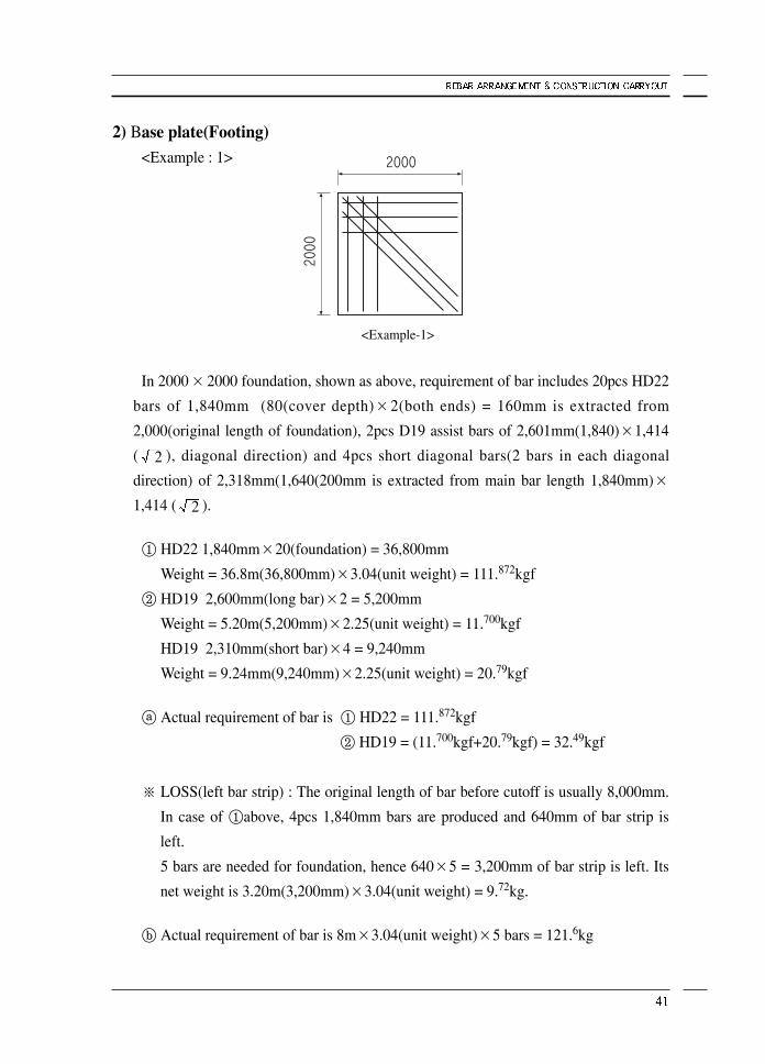
2) Base plate(Footing)<Example : 1>
In 2000×2000 foundation, shown as above, requirement of bar includes 20pcs HD22
bars of 1,840mm (80(cover depth)×2(both ends) = 160mm is extracted from
2,000(original length of foundation), 2pcs D19 assist bars of 2,601mm(1,840)×1,414
( 2 ), diagonal direction) and 4pcs short diagonal bars(2 bars in each diagonal
direction) of 2,318mm(1,640(200mm is extracted from main bar length 1,840mm)×1,414 ( 2 ).
① HD22 1,840mm×20(foundation) = 36,800mm
Weight = 36.8m(36,800mm)×3.04(unit weight) = 111.872kgf
② HD19 2,600mm(long bar)×2 = 5,200mm
Weight = 5.20m(5,200mm)×2.25(unit weight) = 11.700kgf
HD19 2,310mm(short bar)×4 = 9,240mm
Weight = 9.24mm(9,240mm)×2.25(unit weight) = 20.79kgf
ⓐ Actual requirement of bar is ① HD22 = 111.872kgf
② HD19 = (11.700kgf+20.79kgf) = 32.49kgf
※ LOSS(left bar strip) : The original length of bar before cutoff is usually 8,000mm.
In case of ①above, 4pcs 1,840mm bars are produced and 640mm of bar strip is
left.
5 bars are needed for foundation, hence 640×5 = 3,200mm of bar strip is left. Its
net weight is 3.20m(3,200mm)×3.04(unit weight) = 9.72kg.
ⓑ Actual requirement of bar is 8m×3.04(unit weight)×5 bars = 121.6kg
<Example-1>
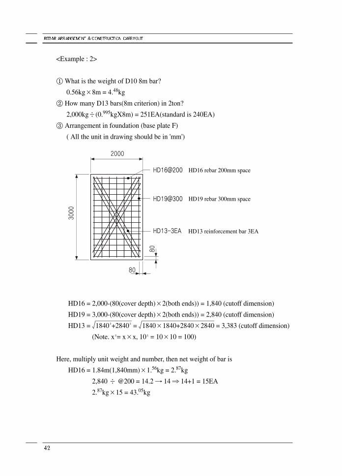
<Example : 2>
① What is the weight of D10 8m bar?
0.56kg×8m = 4.48kg
② How many D13 bars(8m criterion) in 2ton?
2,000kg÷(0.995kgX8m) = 251EA(standard is 240EA)
③ Arrangement in foundation (base plate F)
( All the unit in drawing should be in 'mm')
HD16 = 2,000-(80(cover depth)×2(both ends)) = 1,840 (cutoff dimension)
HD19 = 3,000-(80(cover depth)×2(both ends)) = 2,840 (cutoff dimension)
HD13 = 1840₂+2840
₂= 1840×1840+2840×2840 = 3,383 (cutoff dimension)
(Note. x₂= x×x, 10₂= 10×10 = 100)
Here, multiply unit weight and number, then net weight of bar is
HD16 = 1.84m(1,840mm)×1.56kg = 2.87kg
2,840 ÷ @200 = 14.2 → 14 ⇒ 14+1 = 15EA
2.87kg×15 = 43.05kg
HD16 rebar 200mm space
HD19 rebar 300mm space
HD13 reinforcement bar 3EA
HD19 = 2.84m×2.25kg = 6.39kg
1,840 ÷ @300 = 6.13 → 6 ⇒ 6+1 = 7EA
6.40kg×7 = 43.73kg
HD13 = 3.38m(3,380mm)×0.995kg = 3.36kg
Weight = 3.36kg×assist bar(3+3) = 20.16kg
※Among 6 assist bars, two(2) of them in 3,380mm and the other(4) in 12,320mm
(4x3,080mm : 300mm shorter)
Net weight is 43.05+44.73+21.60 = 109.38kg and add 5% extra, hence 114.84kg is
required.
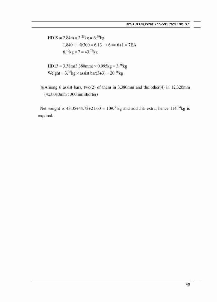
3) Base(footing) and pillar
As various footing types like continues footing, single footing and mat footing, there
are many shapes of footing, that is, triangle, right triangle, square, rectangle, pentagon,
circle, multi-layer plate, etc.
In this book triangle shape footing and single reinforcement footing are dealt with.
In case of footing shown left cover
depth, the type of bar and the size of
bar should be considered.
In addition, the reinforcement at
footing-pillar junction should be
included here.
Before bar cutoff, the size of C1,
the area of main reinforcement, the
size of hoop and the spacing of
stirrup are all considered consulting
the bar list.
Calculation :
Footing shown left is in contact
with soil, hence cover depth is
80mm at each end(80×2 = 160 at
both ends).
160mm is extracted from footing
length 2,000mm, and this(1,840mm)
is divided with spacing 200mm.
Then 10 reinforcement(at every 9
spacing +1 at the end) is required
here.
Now reinforcement is in two
directions and therefore we need 20
reinforcements.
F1 plane
Section
cover50
cover80
HD22@200
HD22@200
D10@300
HD22-8EA
D10@300upper part, lower part @150
HD19-6EA
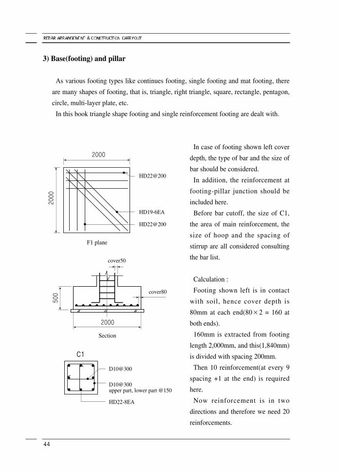
4) PillarSimilar to footing, there are many shapes of pillar, that is, triangle, right triangle,
square, rectangle, pentagon. circle, etc.
The worker is recommended to earn a lot of working experience.
① Calculation of pillar
In calculation, tie hoop, stirrup, main bars
in column and the others should be
included here.
First extract cover depth from hoop size
(400mm), and cover depth in the basement
and above the ground should be different.
Net length cover depth 400 - (40+40) =
320 (dimension)×4(4sides) ⇒ 1,280 +
100mm of hook then, cutoff length is
1,380mm.
Since net length of hook is 100mm, only
100mm of extra length is added here.
If the bar size is D10, one end is hooked
in circular, so 2 times of bar diameter
(20mm) is extracted here, As 5 hooks are
needed and hook length is 100mm at each
end(200mm in total), 80mm is extracted
from 100mm.
Then this 80mm is added to produce
200mm of hook length.
D10@300
HD22-8EA
D10@300upper part, lower part@150
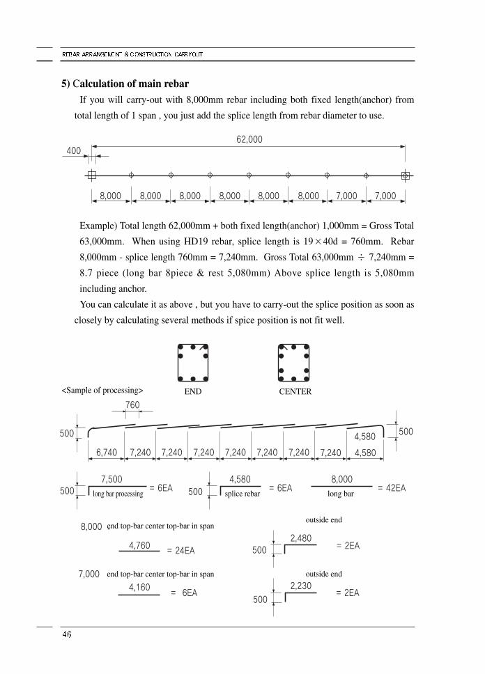
5) Calculation of main rebarIf you will carry-out with 8,000mm rebar including both fixed length(anchor) from
total length of 1 span , you just add the splice length from rebar diameter to use.
Example) Total length 62,000mm + both fixed length(anchor) 1,000mm = Gross Total
63,000mm. When using HD19 rebar, splice length is 19×40d = 760mm. Rebar
8,000mm - splice length 760mm = 7,240mm. Gross Total 63,000mm ÷ 7,240mm =
8.7 piece (long bar 8piece & rest 5,080mm) Above splice length is 5,080mm
including anchor.
You can calculate it as above , but you have to carry-out the splice position as soon as
closely by calculating several methods if spice position is not fit well.
END
long bar processing splice rebar long bar
outside end
outside end
end top-bar center top-bar in span
end top-bar center top-bar in span
CENTER<Sample of processing>
6) Calculation of top rebarPlease refer to the method in construction site as follows because it is very difficult to
explain in theory.
If 1 span is 8,000mm, 4,000mm will be center part and add 40times(40d) + rebar
thickness is the length of top rebar in center part & end.
You cut as 4,000mm +760mm = 4,760mm.
※ When assembling current processing status , center part is from beam to upper part
rebar splice position and end is lower part rebar splice position if splice rebar 2 pcs
4,580mm + long bar processed 1pc as upper part rebar and splice rebar 1pc
4,580mm + long bar processed 2pcs as lower part rebar will be used.
And so, you assemble it mutually crossed and upper part is 2 bar from 3 bar from
splice position.
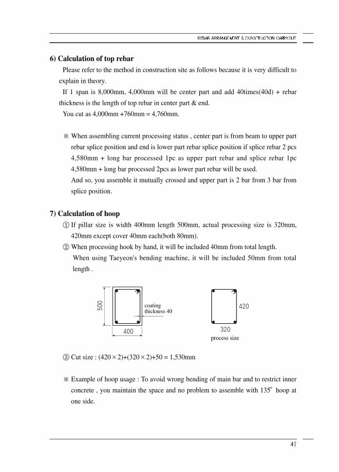
7) Calculation of hoop① If pillar size is width 400mm length 500mm, actual processing size is 320mm,
420mm except cover 40mm each(both 80mm).
② When processing hook by hand, it will be included 40mm from total length.
When using Taeyeon's bending machine, it will be included 50mm from total
length .
③ Cut size : (420×2)+(320×2)+50 = 1,530mm
※ Example of hoop usage : To avoid wrong bending of main bar and to restrict inner
concrete , you maintain the space and no problem to assemble with 135°hoop at
one side.
coating thickness 40
process size
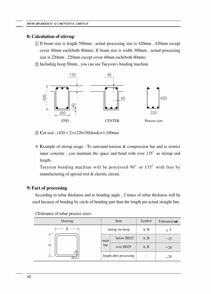
8) Calculation of stirrup① If beam size is length 500mm , actual processing size is 420mm , 420mm except
cover 40mm each(both 80mm). If beam size is width 300mm , actual processing
size is 220mm , 220mm except cover 40mm each(both 80mm).
② Including hoop 50mm , you can use Taeyeon's bending machine.
③ Cut size : (420×2)+(220+50(hook)=1,100mm
※ Example of stirrup usage : To surround tension & compression bar and to restrict
inner concrete , you maintain the space and bend with over 135°as stirrup end
length.
Taeyeon bending machine will be processed 90°or 135°with free by
manufacturing of special tool & electric circuit.
9) Fact of processingAccording to rebar thickness and to bending angle , 2 times of rebar thickness will be
used because of bending by circle of bending part than the length per actual straight line.
<Tolerance of rebar process size>
Item
stirrup, tie hoop
below HD25
over HD29
length after processing
Symbol
A, B
A, B
A, B
-
Tolerance( )
5
15
20
20
mainbar
Drawing
CENTEREND Process size
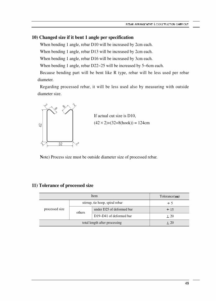
10) Changed size if it bent 1 angle per specificationWhen bending 1 angle, rebar D10 will be increased by 2cm each.
When bending 1 angle, rebar D13 will be increased by 2cm each.
When bending 1 angle, rebar D16 will be increased by 3cm each.
When bending 1 angle, rebar D22~25 will be increased by 5~6cm each.
Because bending part will be bent like R type, rebar will be less used per rebar
diameter.
Regarding processed rebar, it will be less used also by measuring with outside
diameter size.
Note) Process size must be outside diameter size of processed rebar.
11) Tolerance of processed size
processed sizeothers
stirrup, tie hoop, spiral rebar
under D25 of deformed bar
D19~D41 of deformed bar
total length after processing
Tolerance( )
5
15
20
20
Item
If actual cut size is D10,
(42×2)+(32+8(hook)) = 124cm
11. Foundation(Base) rebar arrangement
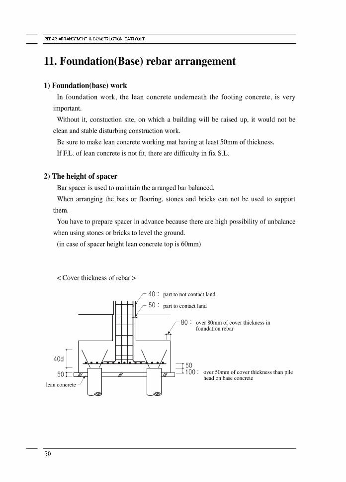
1) Foundation(base) workIn foundation work, the lean concrete underneath the footing concrete, is very
important.
Without it, constuction site, on which a building will be raised up, it would not be
clean and stable disturbing construction work.
Be sure to make lean concrete working mat having at least 50mm of thickness.
If F.L. of lean concrete is not fit, there are difficulty in fix S.L.
2) The height of spacerBar spacer is used to maintain the arranged bar balanced.
When arranging the bars or flooring, stones and bricks can not be used to support
them.
You have to prepare spacer in advance because there are high possibility of unbalance
when using stones or bricks to level the ground.
(in case of spacer height lean concrete top is 60mm)
< Cover thickness of rebar >
part to not contact land
lean concrete
part to contact land
over 80mm of cover thickness infoundation rebar
over 50mm of cover thickness than pilehead on base concrete
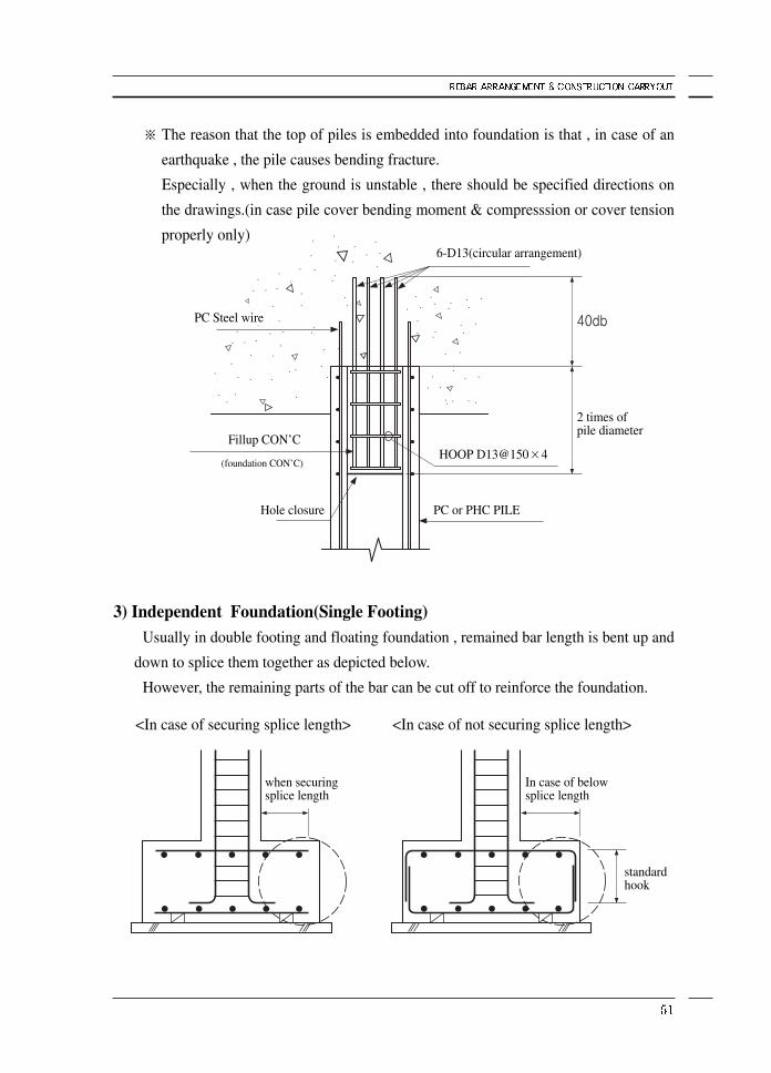
※ The reason that the top of piles is embedded into foundation is that , in case of an
earthquake , the pile causes bending fracture.
Especially , when the ground is unstable , there should be specified directions on
the drawings.(in case pile cover bending moment & compresssion or cover tension
properly only)
3) Independent Foundation(Single Footing)Usually in double footing and floating foundation , remained bar length is bent up and
down to splice them together as depicted below.
However, the remaining parts of the bar can be cut off to reinforce the foundation.
6-D13(circular arrangement)
HOOP D13@150×4
2 times ofpile diameter
PC or PHC PILE
when securingsplice length
In case of belowsplice length
standardhook
<In case of securing splice length> <In case of not securing splice length>
Hole closure
Fillup CON’C
PC Steel wire
(foundation CON’C)
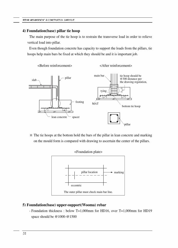
4) Foundation(base) pillar tie hoopThe main purpose of the tie hoop is to restrain the transverse load in order to relieve
vertical load into pillar.
Even though foundation concrete has capacity to support the loads from the pillars, tie
hoops help main bars be fixed at which they should be and it is important job.
※ The tie hoops at the bottom hold the bars of the pillar in lean concrete and marking
on the mould form is compared with drawing to ascertain the center of the pillars.
5) Foundation(base) upper-support(Wooma) rebar - Foundation thickness : below T=1,000mm for HD16, over T=1,000mm for HD19
space should be @1000-@1500
<Before reinforcement>
<Foundation plate>
<After reinforcement>
slab
main bar
tying
MAT
pillartie hoop should be@300 distance perthe drawing regulation,
bottom tie hoop
pillar
marking
eccentric
pillar location
The outer pillar must check main bar line.
footing
spacerlean concrete
12. Pillar rebar arrangement
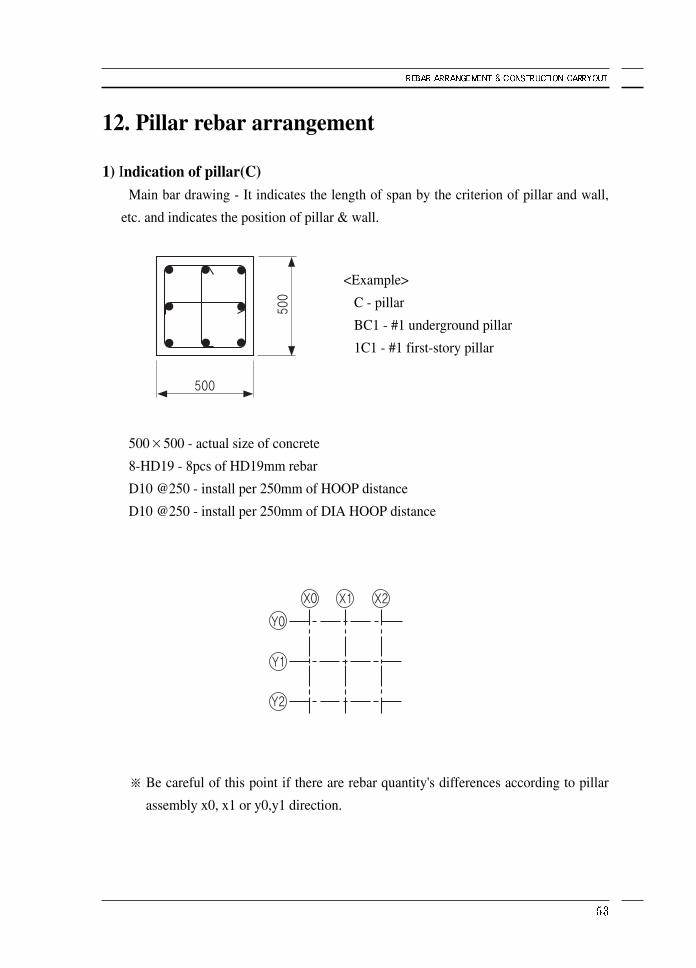
1) Indication of pillar(C)Main bar drawing - It indicates the length of span by the criterion of pillar and wall,
etc. and indicates the position of pillar & wall.
500×500 - actual size of concrete
8-HD19 - 8pcs of HD19mm rebar
D10 @250 - install per 250mm of HOOP distance
D10 @250 - install per 250mm of DIA HOOP distance
※ Be careful of this point if there are rebar quantity's differences according to pillar
assembly x0, x1 or y0,y1 direction.
<Example>
C - pillar
BC1 - #1 underground pillar
1C1 - #1 first-story pillar
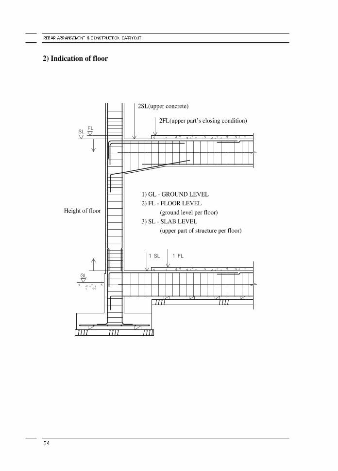
2) Indication of floor
2SL(upper concrete)
2FL(upper part’s closing condition)
1) GL - GROUND LEVEL
2) FL - FLOOR LEVEL
(ground level per floor)
3) SL - SLAB LEVEL
(upper part of structure per floor)
Height of floor
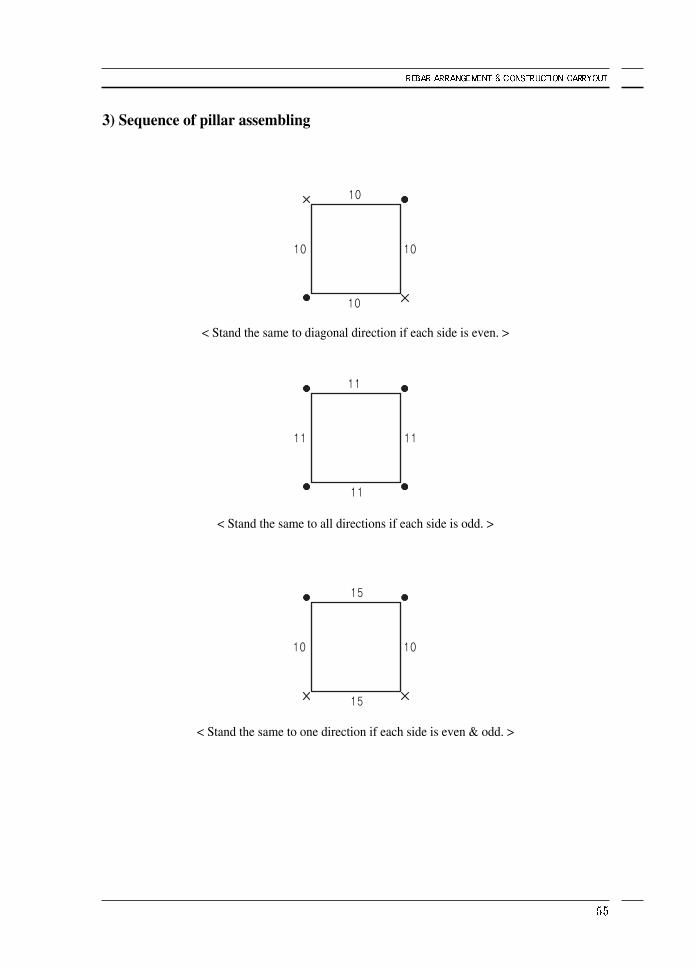
3) Sequence of pillar assembling
< Stand the same to one direction if each side is even & odd. >
< Stand the same to all directions if each side is odd. >
< Stand the same to diagonal direction if each side is even. >
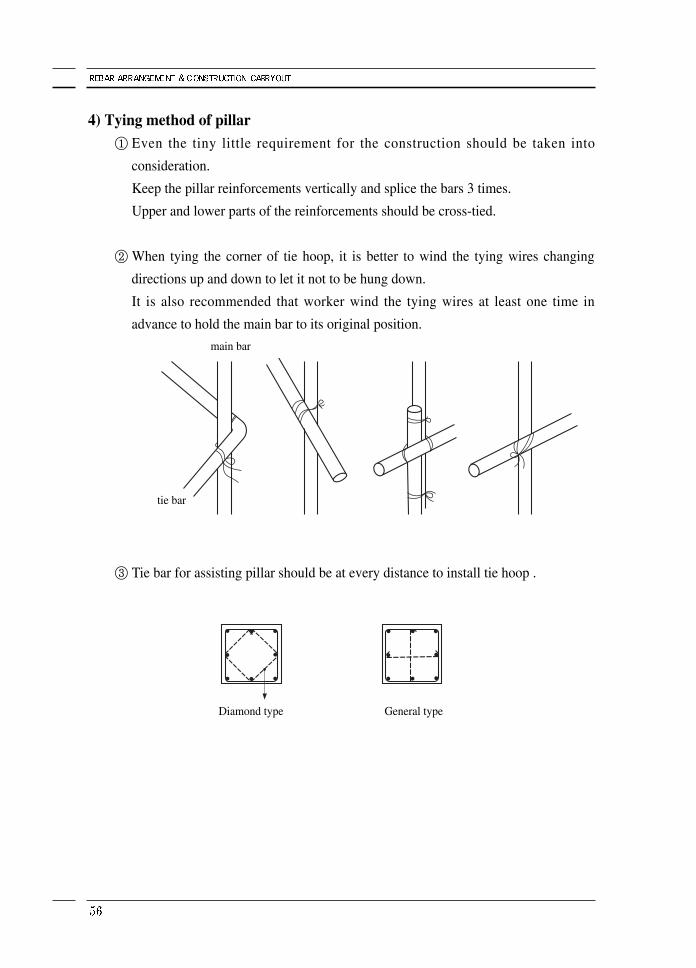
4) Tying method of pillar① Even the tiny little requirement for the construction should be taken into
consideration.
Keep the pillar reinforcements vertically and splice the bars 3 times.
Upper and lower parts of the reinforcements should be cross-tied.
② When tying the corner of tie hoop, it is better to wind the tying wires changing
directions up and down to let it not to be hung down.
It is also recommended that worker wind the tying wires at least one time in
advance to hold the main bar to its original position.
③ Tie bar for assisting pillar should be at every distance to install tie hoop .
main bar
Diamond type General type
tie bar
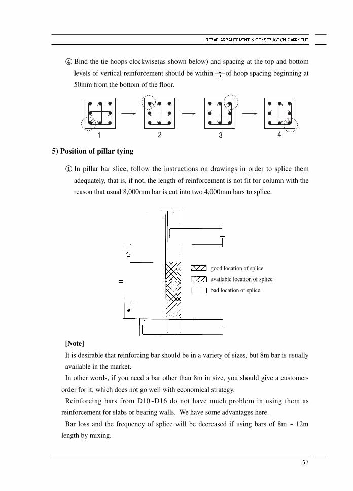
④ Bind the tie hoops clockwise(as shown below) and spacing at the top and bottom
levels of vertical reinforcement should be within of hoop spacing beginning at
50mm from the bottom of the floor.
5) Position of pillar tying
① In pillar bar slice, follow the instructions on drawings in order to splice them
adequately, that is, if not, the length of reinforcement is not fit for column with the
reason that usual 8,000mm bar is cut into two 4,000mm bars to splice.
[Note]
It is desirable that reinforcing bar should be in a variety of sizes, but 8m bar is usually
available in the market.
In other words, if you need a bar other than 8m in size, you should give a customer-
order for it, which does not go well with economical strategy.
Reinforcing bars from D10~D16 do not have much problem in using them as
reinforcement for slabs or bearing walls. We have some advantages here.
Bar loss and the frequency of splice will be decreased if using bars of 8m ~ 12m
length by mixing.
good location of splice
available location of splice
bad location of splice
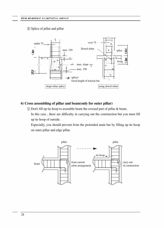
② Splice of pillar and pillar
6) Cross assembling of pillar and beam(only for outer pillar)① Don't fill up tie hoop to assemble beam the crossed part of pillar & beam.
In this case , there are difficulty in carrying out the construction but you must fill
up tie hoop of outside.
Especially, you should prevent from the protruded main bar by filling up tie hoop
on outer pillar and edge pillar.
under 75 over 75
Dowel rebarmax. 150
max. slope
slope rebar splice using dowel rebar
fixing
splice
max. 150
splice/fixed length of tension bar
pillar pillar
beam carry-outof construction
from currentrebar arrangement
tie hoop
② In case over 600mm of pillar size , you should fill up support tie hoop by shop
drawing.
You should get rid of support tie hoop in order to worker's entrance to pillar tube
to connect #8 wire for working of pillar outer appearance.
After this, the worker should not forget to bind the assist wire before he gets out.
※ In case the splice length for pillar splice is shorter than required, be sure to destroy
the concrete to maintain splice length but it is impossible possibility to execute
actually.
Therefore, you should check the availability of welding splice, compressed splice,
mechanical splice.
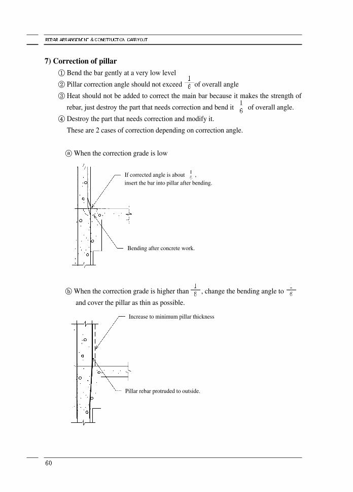
7) Correction of pillar① Bend the bar gently at a very low level
② Pillar correction angle should not exceed of overall angle
③ Heat should not be added to correct the main bar because it makes the strength of
rebar, just destroy the part that needs correction and bend it of overall angle.
④ Destroy the part that needs correction and modify it.
These are 2 cases of correction depending on correction angle.
ⓐ When the correction grade is low
ⓑ When the correction grade is higher than , change the bending angle to
and cover the pillar as thin as possible.
If corrected angle is about ,insert the bar into pillar after bending.
Bending after concrete work.
Increase to minimum pillar thickness
Pillar rebar protruded to outside.
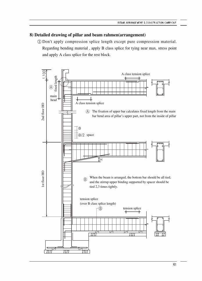
8) Detailed drawing of pillar and beam rahmen(arrangement)① Don't apply compression splice length except pure compression material.
Regarding bending material , apply B class splice for tying near max. stress point
and apply A class splice for the rest block.
2nd
floo
r HO
fixe
d le
ngth
A class tension splice
A class tension splice
tension splice(over B class splice length)
tension splice
space
The fixation of upper bar calculates fixed length from the mainbar bend area of pillar’s upper part, not from the inside of pillar
When the beam is arranged, the bottom bar should be all tied,and the stirrup upper binding supported by spacer should betied 2,3 times tightly.1s
t flo
or H
O
main head
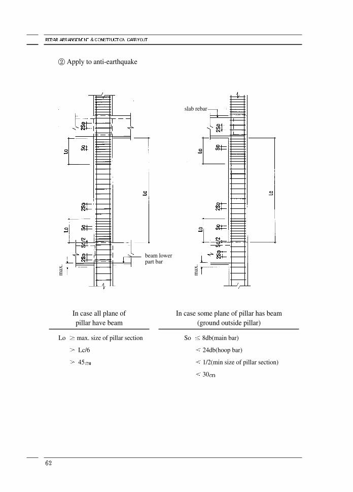
② Apply to anti-earthquake
In case all plane of pillar have beam
Lo max. size of pillar section
Lc/6
45
In case some plane of pillar has beam(ground outside pillar)
So 8db(main bar)
24db(hoop bar)
1/2(min size of pillar section)
30
slab rebar
beam lowerpart bar
max
.
max
.
13. Beam rebar arrangement
1) Principle of beam rebar arrangement① Calculate the size and depth of beams according to the drawing and arrange them
in a suggested order, that is, exterior beams and big beams(G) & deep beams first
and then binding small beams(B beams) later.
② Supervisor has to check if the bar used at the top span meets the requirement on
the drawing.
Shorter bar than required might be used to save cost when the span is longer than
8,000mm, the bar standard.
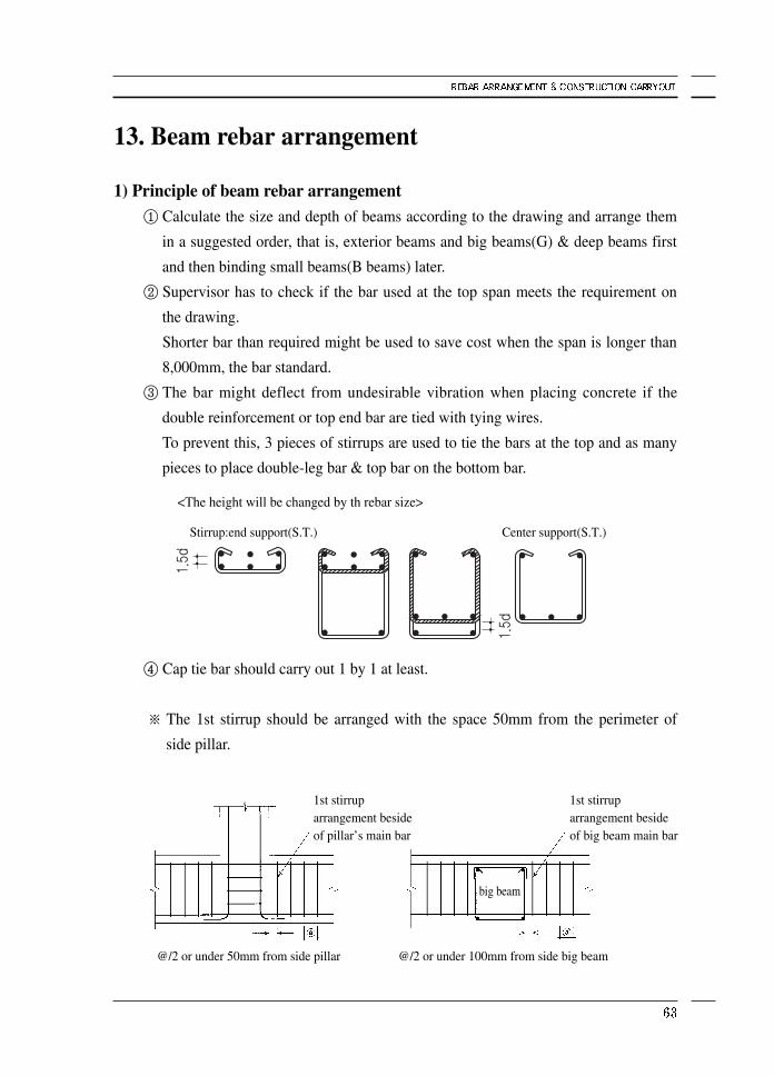
③ The bar might deflect from undesirable vibration when placing concrete if the
double reinforcement or top end bar are tied with tying wires.
To prevent this, 3 pieces of stirrups are used to tie the bars at the top and as many
pieces to place double-leg bar & top bar on the bottom bar.
④ Cap tie bar should carry out 1 by 1 at least.
※ The 1st stirrup should be arranged with the space 50mm from the perimeter of
side pillar.
@/2 or under 50mm from side pillar @/2 or under 100mm from side big beam
<The height will be changed by th rebar size>
Stirrup:end support(S.T.)
1st stirruparrangement besideof pillar’s main bar
1st stirruparrangement besideof big beam main bar
big beam
Center support(S.T.)
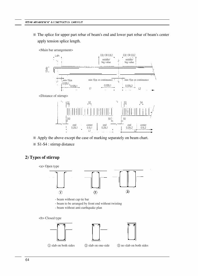
※ The splice for upper part rebar of beam's end and lower part rebar of beam's center
apply tension splice length.
※ Apply the above except the case of marking separately on beam chart.
※ S1-S4 : stirrup distance
2) Types of stirrup
Ldh
S1 S2 S3
5050
end0.25L1
center0.5L1L1 L2
end0.25L1
end0.25L2
center0.5L2
50
S4
12db
0.3L1 OR 0.3L2 0.3L1 OR 0.3L2
min 15㎝ min 15㎝ or continuance min 15㎝ or continuance0.125L1
0.125L1 0.125L1L1 L2
0.125L2
<Main bar arrangement>
<Distance of stirrup>
- beam without cap tie bar- beam to be arranged by front end without twisting- beam without anti-earthquake plan
① slab on both sides ② slab on one-side ③ no slab on both sides
<a> Open type
<b> Closed type
middle/big value
middle/big value
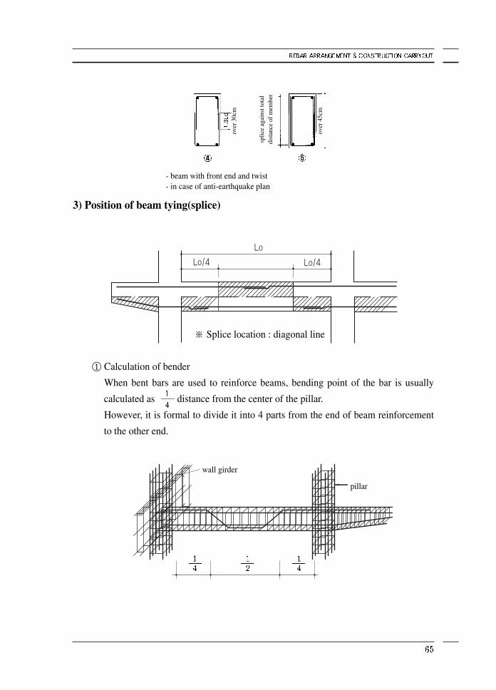
3) Position of beam tying(splice)
※ Splice location : diagonal line
① Calculation of bender
When bent bars are used to reinforce beams, bending point of the bar is usually
calculated as distance from the center of the pillar.
However, it is formal to divide it into 4 parts from the end of beam reinforcement
to the other end.
- beam with front end and twist- in case of anti-earthquake plan
wall girder
pillar
over
30c
m
over
45c
m
splic
e ag
ains
t tot
aldi
stan
ce o
f mem
ber
② An example for processing
Anchorage(fixed) bars are classified as the top bars and the bottom bars, when the
former have tensile loads and the later have compression loads.
Therefore, the top bars and bottom bars set fixed splice length with same method
because it has difficulty in working separately for processing and
assembling.(criterion of concrete structure plan)
In a real construction, 40d is used for both of them for convenience sake.
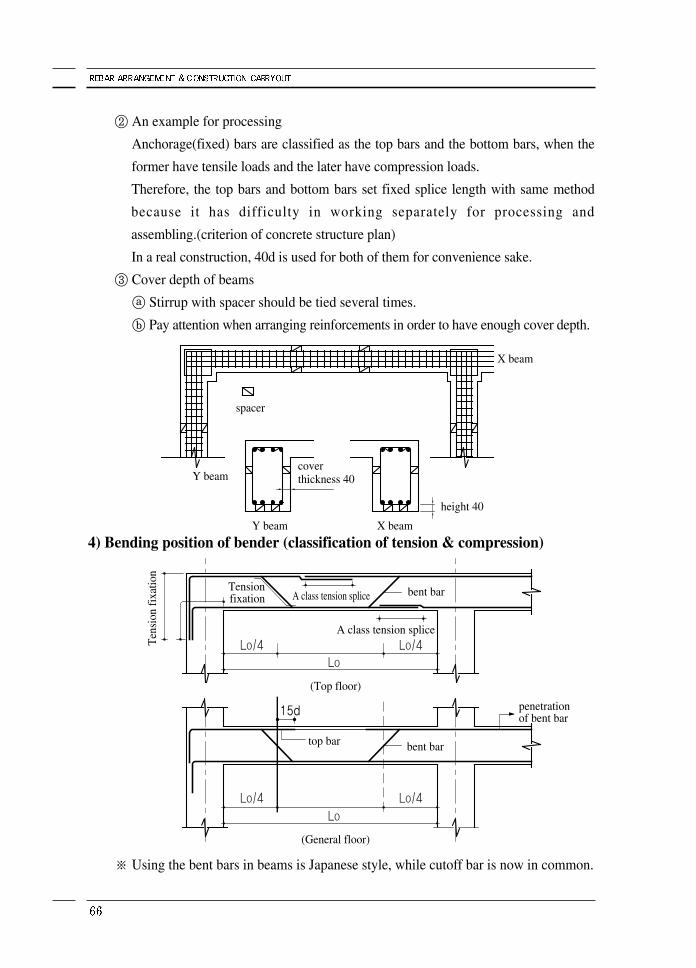
③ Cover depth of beams
ⓐ Stirrup with spacer should be tied several times.
ⓑ Pay attention when arranging reinforcements in order to have enough cover depth.
4) Bending position of bender (classification of tension & compression)
※ Using the bent bars in beams is Japanese style, while cutoff bar is now in common.
spacer
Y beam
Y beam X beam
X beam
Ten
sion
fixa
tion
Tensionfixation A class tension splice
A class tension splice
bent bar
penetrationof bent bar
top bar
(Top floor)
(General floor)
bent bar
height 40
coverthickness 40
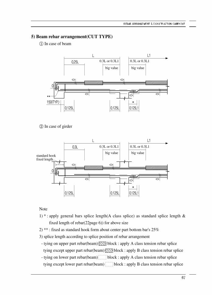
5) Beam rebar arrangement(CUT TYPE)① In case of beam
② In case of girder
Note
1) * : apply general bars splice length(A class splice) as standard splice length &
fixed length of rebar(22page 6)) for above size
2) ** : fixed as standard hook form about center part bottom bar's 25%
3) splice length according to splice position of rebar arrangement
- tying on upper part rebar(beam) block : apply A class tension rebar splice
tying except upper part rebar(beam) block : apply B class tension rebar splice
- tying on lower part rebar(beam) block : apply A class tension rebar splice
tying except lower part rebar(beam) block : apply B class tension rebar splice
0.3L or 0.3L1 0.3L or 0.3L1
big value big value
0.3L or 0.3L1 0.3L or 0.3L1
big value big valuestandard hookfixed length
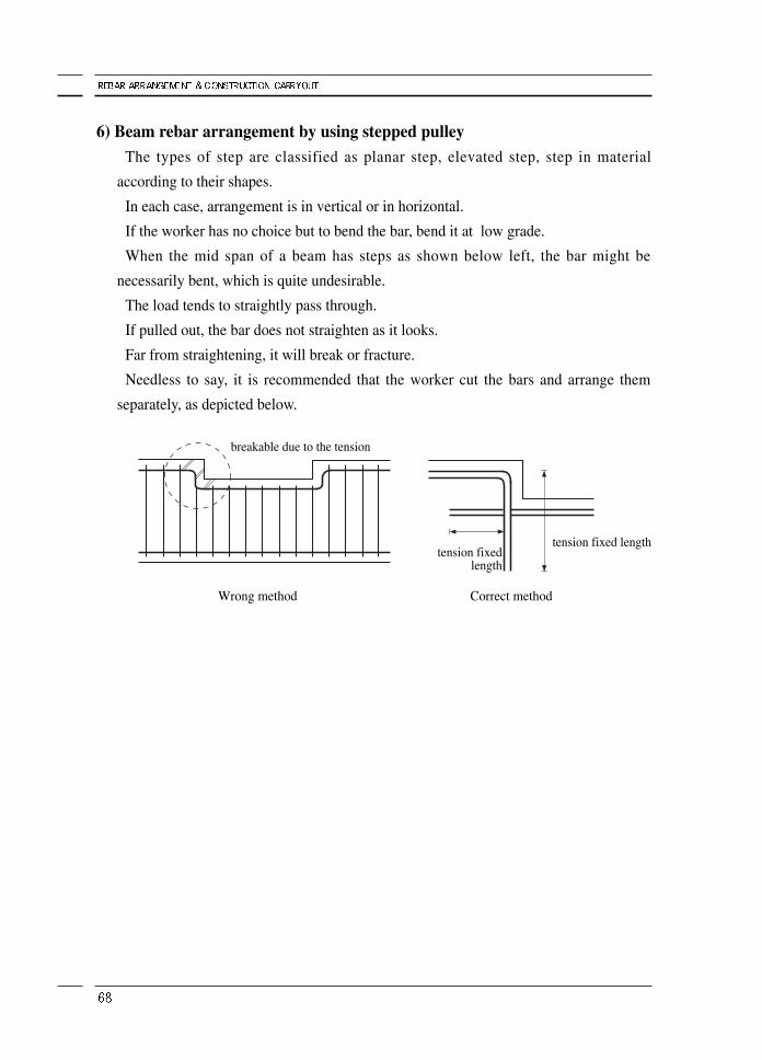
6) Beam rebar arrangement by using stepped pulleyThe types of step are classified as planar step, elevated step, step in material
according to their shapes.
In each case, arrangement is in vertical or in horizontal.
If the worker has no choice but to bend the bar, bend it at low grade.
When the mid span of a beam has steps as shown below left, the bar might be
necessarily bent, which is quite undesirable.
The load tends to straightly pass through.
If pulled out, the bar does not straighten as it looks.
Far from straightening, it will break or fracture.
Needless to say, it is recommended that the worker cut the bars and arrange them
separately, as depicted below.
tension fixed lengthtension fixed
length
breakable due to the tension
Wrong method Correct method
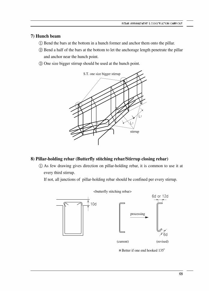
7) Hunch beam① Bend the bars at the bottom in a hunch former and anchor them onto the pillar.
② Bend a half of the bars at the bottom to let the anchorage length penetrate the pillar
and anchor near the hunch point.
③ One size bigger stirrup should be used at the hunch point.
8) Pillar-holding rebar (Butterfly stitching rebar/Stirrup closing rebar)① As few drawing gives direction on pillar-holding rebar, it is common to use it at
every third stirrup.
If not, all junctions of pillar-holding rebar should be confined per every stirrup.
S.T. one size bigger stirrup
stirrup
processing
(current) (revised)
<butterfly stitching rebar>
Better if one end hooked 135°
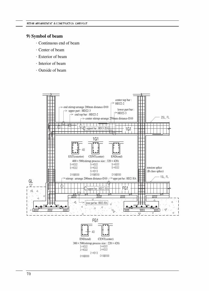
9) Symbol of beam·Continuous end of beam
·Center of beam
·Exterior of beam
·Interior of beam
·Outside of beam
end stirrup:arrange 200mm distance-D10upper part : HD22-3
end top bar : HD22-2
EXT(exterior) CENT(center)
400×500(stirrup process size : 320×420)
300×500(stirrup process size : 220×420)
stirrup : arrange 200mm distance-D10
tension splice(B class splice)
upper part bar : HD22-3EA
END(end)
END(end) CENT(center)
center stirrup-arrange 250mm distance-D10
center top bar : HD22-2
lower part bar :HD22-3
support bar : HD13-2EA
support bar : HD22-3EA
lower part bar : HD22-3EA
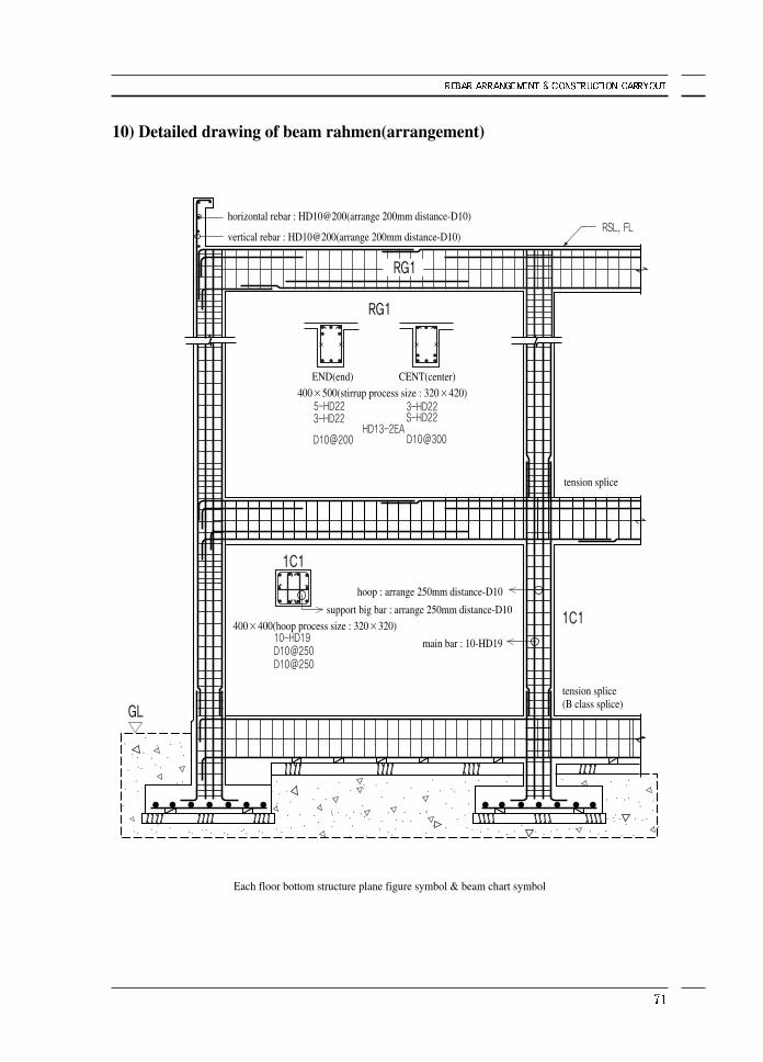
10) Detailed drawing of beam rahmen(arrangement)
horizontal rebar : HD10@200(arrange 200mm distance-D10)
vertical rebar : HD10@200(arrange 200mm distance-D10)
400×500(stirrup process size : 320×420)
400×400(hoop process size : 320×320)
tension splice(B class splice)
Each floor bottom structure plane figure symbol & beam chart symbol
END(end) CENT(center)
tension splice
hoop : arrange 250mm distance-D10
main bar : 10-HD19
support big bar : arrange 250mm distance-D10
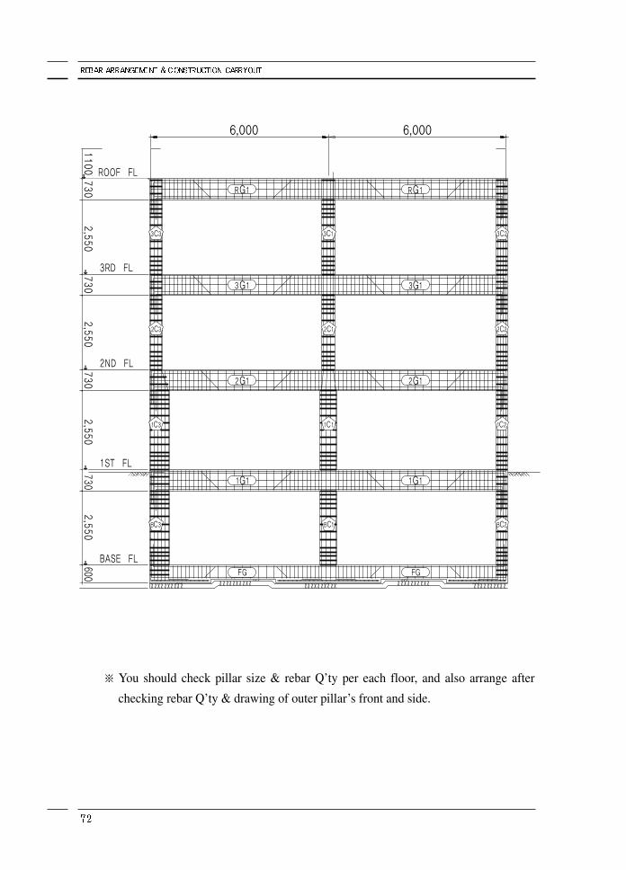
※ You should check pillar size & rebar Q’ty per each floor, and also arrange after
checking rebar Q’ty & drawing of outer pillar’s front and side.
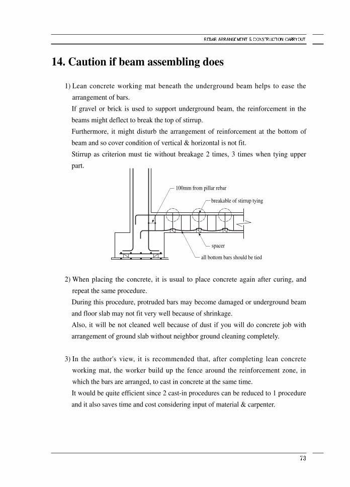
14. Caution if beam assembling does
1) Lean concrete working mat beneath the underground beam helps to ease the
arrangement of bars.
If gravel or brick is used to support underground beam, the reinforcement in the
beams might deflect to break the top of stirrup.
Furthermore, it might disturb the arrangement of reinforcement at the bottom of
beam and so cover condition of vertical & horizontal is not fit.
Stirrup as criterion must tie without breakage 2 times, 3 times when tying upper
part.
2) When placing the concrete, it is usual to place concrete again after curing, and
repeat the same procedure.
During this procedure, protruded bars may become damaged or underground beam
and floor slab may not fit very well because of shrinkage.
Also, it will be not cleaned well because of dust if you will do concrete job with
arrangement of ground slab without neighbor ground cleaning completely.
3) In the author's view, it is recommended that, after completing lean concrete
working mat, the worker build up the fence around the reinforcement zone, in
which the bars are arranged, to cast in concrete at the same time.
It would be quite efficient since 2 cast-in procedures can be reduced to 1 procedure
and it also saves time and cost considering input of material & carpenter.
100mm from pillar rebar
breakable of stirrup tying
spacer
all bottom bars should be tied
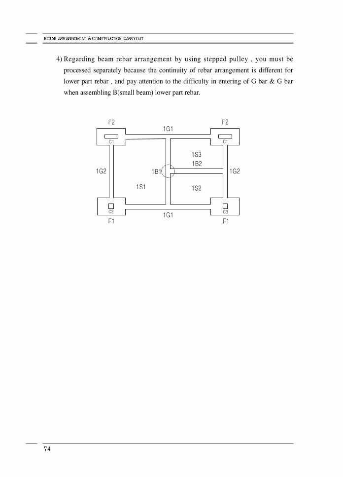
4) Regarding beam rebar arrangement by using stepped pulley , you must be
processed separately because the continuity of rebar arrangement is different for
lower part rebar , and pay attention to the difficulty in entering of G bar & G bar
when assembling B(small beam) lower part rebar.
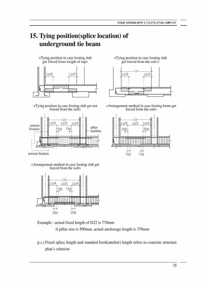
15. Tying position(splice location) of underground tie beam
Example : actual fixed length of D22 is 770mm
if pillar size is 500mm, actual anchorage length is 370mm
p.s.) Fixed splice length and standard hook(anchor) length refers to concrete structure
plan’s criterion
<Tying position in case footing slab get forced from weight of top>
<Tying position in case footing slab get notforced from the soil>
<Arrangement method in case footing slab getforced from the soil>
tension fixation
tensionfixation
<Arrangement method in case footing beam getforced from the soil>
<Tying position in case footing slab get forced from the soil >
pillarmainbar
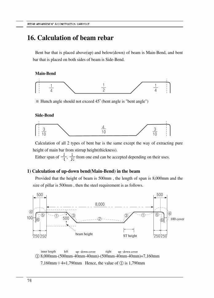
16. Calculation of beam rebar
Bent bar that is placed above(up) and below(down) of beam is Main-Bend, and bent
bar that is placed on both sides of beam is Side-Bend.
Main-Bend
※ Hunch angle should not exceed 45°(bent angle is "bent angle")
Side-Bend
Calculation of all 2 types of bent bar is the same except the way of extracting pure
height of main bar from stirrup height(thickness).
Either span of , from one end can be accepted depending on their uses.
1) Calculation of up-down bend(Main-Bend) in the beamProvided that the height of beam is 500mm , the length of span is 8,000mm and the
size of pillar is 500mm , then the steel requirement is as follows.
① 8,000mm-(500mm-40mm-40mm)-(500mm-40mm-40mm)=7,160mm
7,160mm÷4=1,790mm Hence, the value of ① is 1,790mm
beam height ST height
100 cover
inner length left rightup·down cover up·down cover
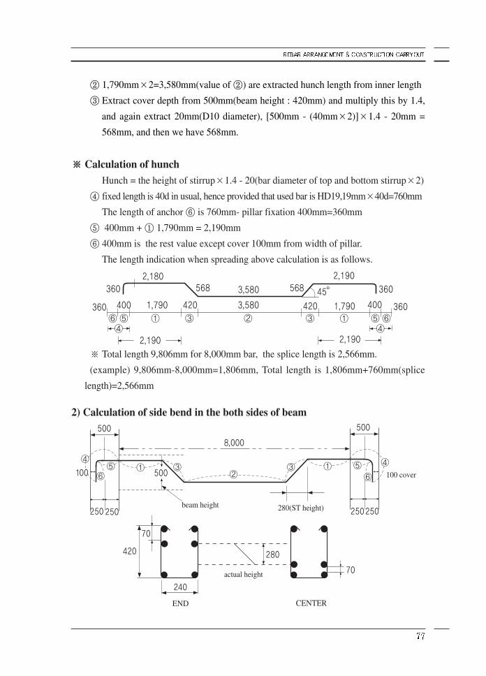
② 1,790mm×2=3,580mm(value of ②) are extracted hunch length from inner length
③ Extract cover depth from 500mm(beam height : 420mm) and multiply this by 1.4,
and again extract 20mm(D10 diameter), [500mm - (40mm×2)]×1.4 - 20mm =
568mm, and then we have 568mm.
※※ Calculation of hunchHunch = the height of stirrup×1.4 - 20(bar diameter of top and bottom stirrup×2)
④ fixed length is 40d in usual, hence provided that used bar is HD19,19mm×40d=760mm
The length of anchor ⑥ is 760mm- pillar fixation 400mm=360mm
⑤ 400mm + ① 1,790mm = 2,190mm
⑥ 400mm is the rest value except cover 100mm from width of pillar.
The length indication when spreading above calculation is as follows.
※ Total length 9,806mm for 8,000mm bar, the splice length is 2,566mm.
(example) 9,806mm-8,000mm=1,806mm, Total length is 1,806mm+760mm(splice
length)=2,566mm
2) Calculation of side bend in the both sides of beam
beam height 280(ST height)
actual height
END CENTER
100 cover
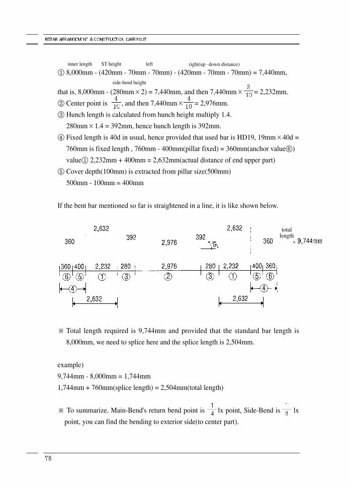
① 8,000mm - (420mm - 70mm - 70mm) - (420mm - 70mm - 70mm) = 7,440mm,
that is, 8,000mm - (280mm×2) = 7,440mm, and then 7,440mm× = 2,232mm.
② Center point is , and then 7,440mm× = 2,976mm.
③ Hunch length is calculated from hunch height multiply 1.4.
280mm×1.4 = 392mm, hence hunch length is 392mm.
④ Fixed length is 40d in usual, hence provided that used bar is HD19, 19mm×40d =
760mm is fixed length , 760mm - 400mm(pillar fixed) = 360mm(anchor value⑥)
value① 2,232mm + 400mm = 2,632mm(actual distance of end upper part)
⑤ Cover depth(100mm) is extracted from pillar size(500mm)
500mm - 100mm = 400mm
If the bent bar mentioned so far is straightened in a line, it is like shown below.
※ Total length required is 9,744mm and provided that the standard bar length is
8,000mm, we need to splice here and the splice length is 2,504mm.
example)
9,744mm - 8,000mm = 1,744mm
1,744mm + 760mm(splice length) = 2,504mm(total length)
※ To summarize, Main-Bend's return bend point is lx point, Side-Bend is lx
point, you can find the bending to exterior side(to center part).
inner length ST height left right(up·down distance)
side-bend height
totallength
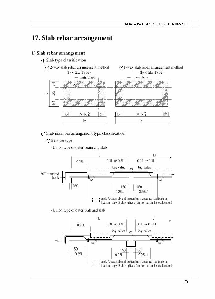
17. Slab rebar arrangement
1) Slab rebar arrangementSlab type classification
2-way slab rebar arrangement method 1-way slab rebar arrangement method
Slab main bar arrangement type classification
Bent bar type
- Union type of outer beam and slab
- Union type of outer wall and slab
(ly < 2lx Type) (ly < 2lx Type)main block main block
90°standardhook
wall
0.3L or 0.3L1
0.3L or 0.3L1 0.3L or 0.3L1
apply A class splice of tension bar if upper part bar tying onlocation (apply B class splice of tension bar on the rest location)
apply A class splice of tension bar if upper part bar tying onlocation (apply B class splice of tension bar on the rest location)
big value
big value big value
big value
0.3L or 0.3L1
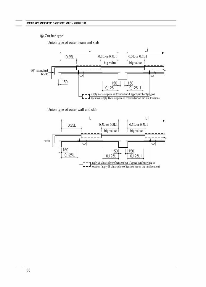
ⓑ Cut bar type
- Union type of outer beam and slab
- Union type of outer wall and slab
90°standardhook
wall
0.3L or 0.3L1
0.3L or 0.3L1 0.3L or 0.3L1
apply A class splice of tension bar if upper part bar tying onlocation (apply B class splice of tension bar on the rest location)
apply A class splice of tension bar if upper part bar tying onlocation (apply B class splice of tension bar on the rest location)
big value
big value big value
big value
0.3L or 0.3L1
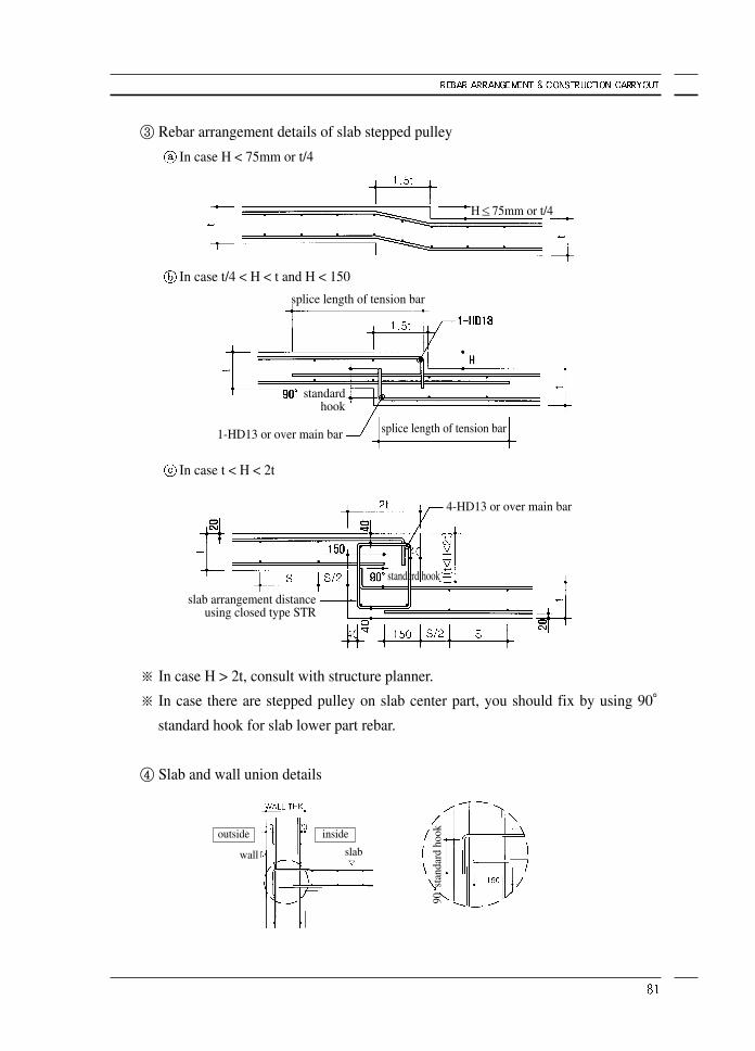
③ Rebar arrangement details of slab stepped pulley
In case H < 75mm or t/4
In case t/4 < H < t and H < 150
In case t < H < 2t
※ In case H > 2t, consult with structure planner.
※ In case there are stepped pulley on slab center part, you should fix by using 90°standard hook for slab lower part rebar.
④ Slab and wall union details
splice length of tension bar
1-HD13 or over main bar
slab arrangement distanceusing closed type STR
4-HD13 or over main bar
splice length of tension bar
standard hook
standard hook
H≤75mm or t/4
outside inside
wall slab
90st
anda
rd h
ook
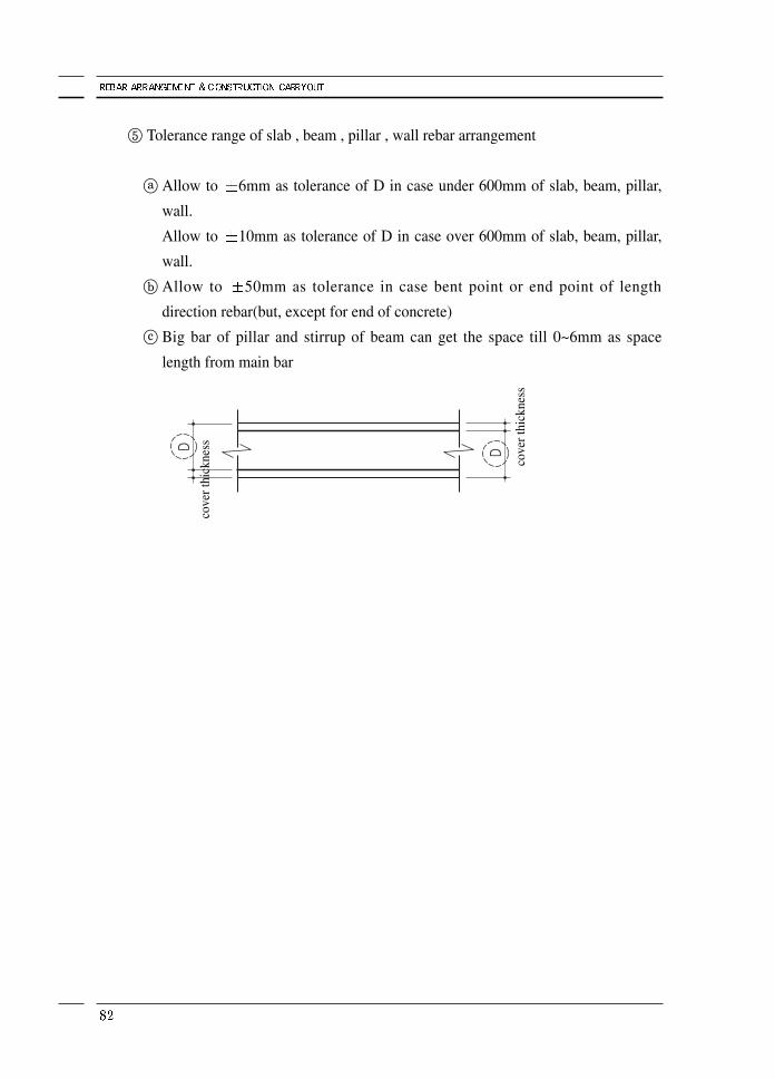
⑤ Tolerance range of slab , beam , pillar , wall rebar arrangement
ⓐ Allow to 6mm as tolerance of D in case under 600mm of slab, beam, pillar,
wall.
Allow to 10mm as tolerance of D in case over 600mm of slab, beam, pillar,
wall.
ⓑ Allow to 50mm as tolerance in case bent point or end point of length
direction rebar(but, except for end of concrete)
ⓒ Big bar of pillar and stirrup of beam can get the space till 0~6mm as space
length from main bar
cove
r thi
ckne
ss
cove
r thi
ckne
ss
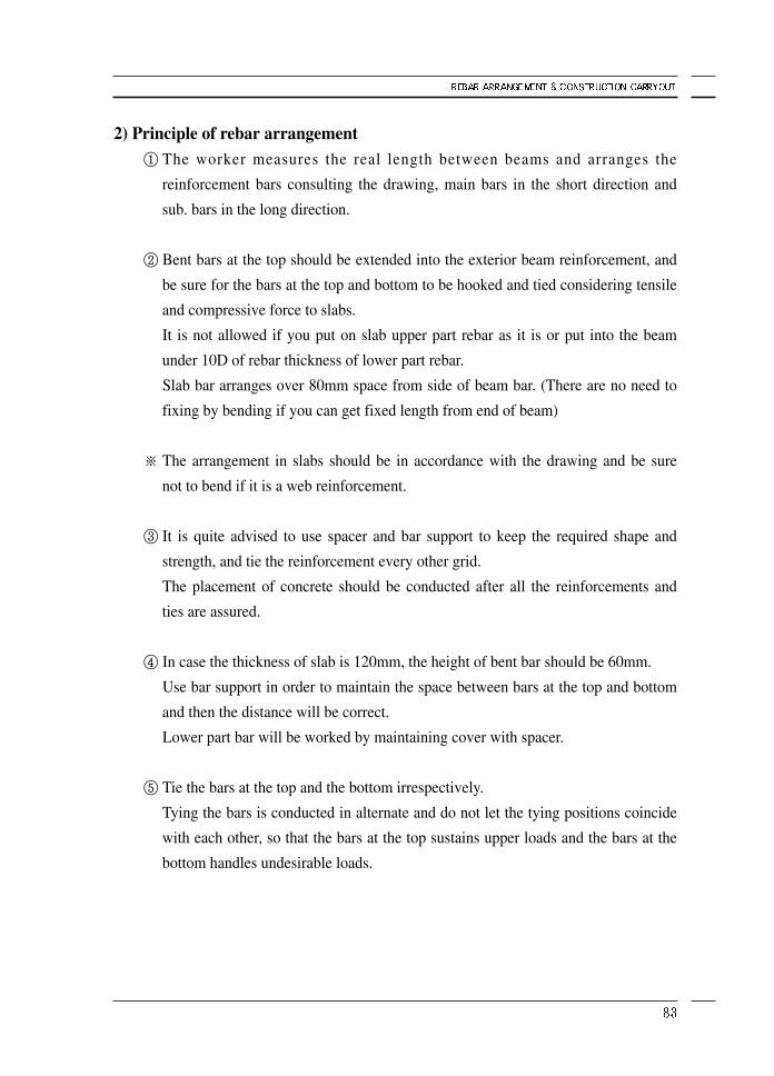
2) Principle of rebar arrangement① The worker measures the real length between beams and arranges the
reinforcement bars consulting the drawing, main bars in the short direction and
sub. bars in the long direction.
② Bent bars at the top should be extended into the exterior beam reinforcement, and
be sure for the bars at the top and bottom to be hooked and tied considering tensile
and compressive force to slabs.
It is not allowed if you put on slab upper part rebar as it is or put into the beam
under 10D of rebar thickness of lower part rebar.
Slab bar arranges over 80mm space from side of beam bar. (There are no need to
fixing by bending if you can get fixed length from end of beam)
※ The arrangement in slabs should be in accordance with the drawing and be sure
not to bend if it is a web reinforcement.
③ It is quite advised to use spacer and bar support to keep the required shape and
strength, and tie the reinforcement every other grid.
The placement of concrete should be conducted after all the reinforcements and
ties are assured.
④ In case the thickness of slab is 120mm, the height of bent bar should be 60mm.
Use bar support in order to maintain the space between bars at the top and bottom
and then the distance will be correct.
Lower part bar will be worked by maintaining cover with spacer.
⑤ Tie the bars at the top and the bottom irrespectively.
Tying the bars is conducted in alternate and do not let the tying positions coincide
with each other, so that the bars at the top sustains upper loads and the bars at the
bottom handles undesirable loads.
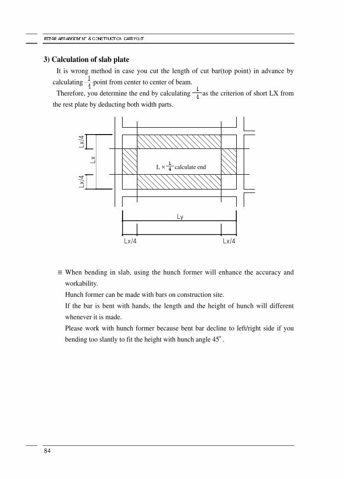
3) Calculation of slab plateIt is wrong method in case you cut the length of cut bar(top point) in advance by
calculating point from center to center of beam.
Therefore, you determine the end by calculating as the criterion of short LX from
the rest plate by deducting both width parts.
※ When bending in slab, using the hunch former will enhance the accuracy and
workability.
Hunch former can be made with bars on construction site.
If the bar is bent with hands, the length and the height of hunch will different
whenever it is made.
Please work with hunch former because bent bar decline to left/right side if you
bending too slantly to fit the height with hunch angle 45°.
L calculate end
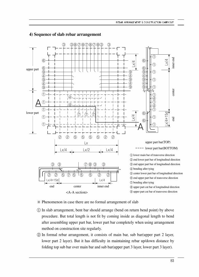
4) Sequence of slab rebar arrangement
※ Phenomenon in case there are no formal arrangement of slab
① In slab arrangement, bent bar should arrange (bend on return bend point) by above
procedure. But total length is not fit by coming inside as diagonal length to bend
after assembling upper part bar, lower part bar completely when using arrangement
method on construction site regularly.
② In formal rebar arrangement, it consists of main bar, sub bar(upper part 2 layer,
lower part 2 layer). But it has difficulty in maintaining rebar up/down distance by
folding top sub bar over main bar and sub bar(upper part 3 layer, lower part 3 layer).
<A-A section>
① lower main bar of transverse direction
② end lower part bar of longitudinal direction
③ end upper part bar of longitudinal direction
④ bending after tying
⑤ center lower part bar of longitudinal direction
⑥ end upper part bar of transverse direction
⑦ bending after tying
⑧ upper part cut bar of longitudinal direction
⑨ upper part cut bar of transverse direction
upper part bar(TOP)
lower part bar(BOTTOM)
inne
r end
upper part
lower part
end inner endcenter
cent
eren
d
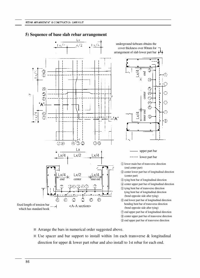
5) Sequence of base slab rebar arrangement
※ Arrange the bars in numerical order suggested above.
※ Use spacer and bar support to install within 1m each transverse & longitudinal
direction for upper & lower part rebar and also install to 1st rebar for each end.
<A-A section>
Lx/4Lx/4 Lx/2inner endend center
Lx/4Lx/4 Lx/2Lx
Lx/4
Lx/4
① lower main bar of transverse direction(end center part)
② center lower part bar of longitudinal direction(center part)
③ tying bent bar of longitudinal direction④ center upper part bar of longitudinal direction⑤ tying bent bar of transverse direction
tying bent bar of longitudinal direction(bend opposite side after tying)
⑥ end lower part bar of longitudinal direction bending bent bar of transverse direction(bend opposite side after tying)
⑦ end upper part bar of longitudinal direction⑧ center upper part bar of transverse direction⑨ end upper part bar of transverse direction
upper part bar
lower part bar
underground tiebeam obtains thecover thickness over 80mm for
arrangement of slab lower part bar
inne
r end
cent
eren
d
fixed length of tension barwhich has standard hook
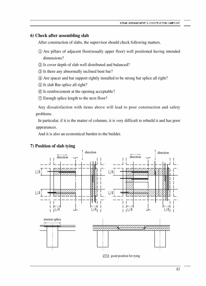
6) Check after assembling slabAfter construction of slabs, the supervisor should check following matters.
① Are pillars of adjacent floor(usually upper floor) well positioned having intended
dimensions?
② Is cover depth of slab well distributed and balanced?
③ Is there any abnormally inclined bent bar?
④ Are spacer and bar support rightly installed to be strong bar splice all right?
⑤ Is slab Bar splice all right?
⑥ Is reinforcement at the opening acceptable?
⑦ Enough splice length to the next floor?
Any dissatisfaction with items above will lead to poor construction and safety
problems.
In particular, if it is the matter of columns, it is very difficult to rebuild it and has poor
appearances.
And it is also an economical burden to the builder.
7) Position of slab tying
direction directiondirection direction
tension splice
good position for tying
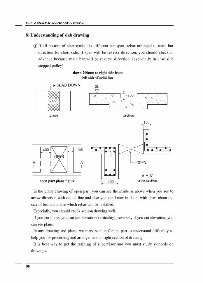
8) Understanding of slab drawing
① If all bottom of slab symbol is different per span, rebar arranged to main bar
direction for short side. If span will be reverse direction, you should check in
advance because main bar will be reverse direction. (especially in case slab
stepped pulley)
In the plane drawing of open part, you can see the inside as above when you see to
arrow direction with dotted line and also you can know in detail with chart about the
size of beam and also which rebar will be installed.
Especially, you should check section drawing well.
If you cut plane, you can see elevation(verticality), reversely if you cut elevation, you
can see plane.
In any drawing and plane, we mark section for the part to understand difficultly to
help you for processing and arrangement on right section of drawing.
It is best way to get the training of supervisor and you must study symbols on
drawings.
down 200mm to right side fromleft side of solid line
open part plane figure
plane section
cross section
SLAB DOWN
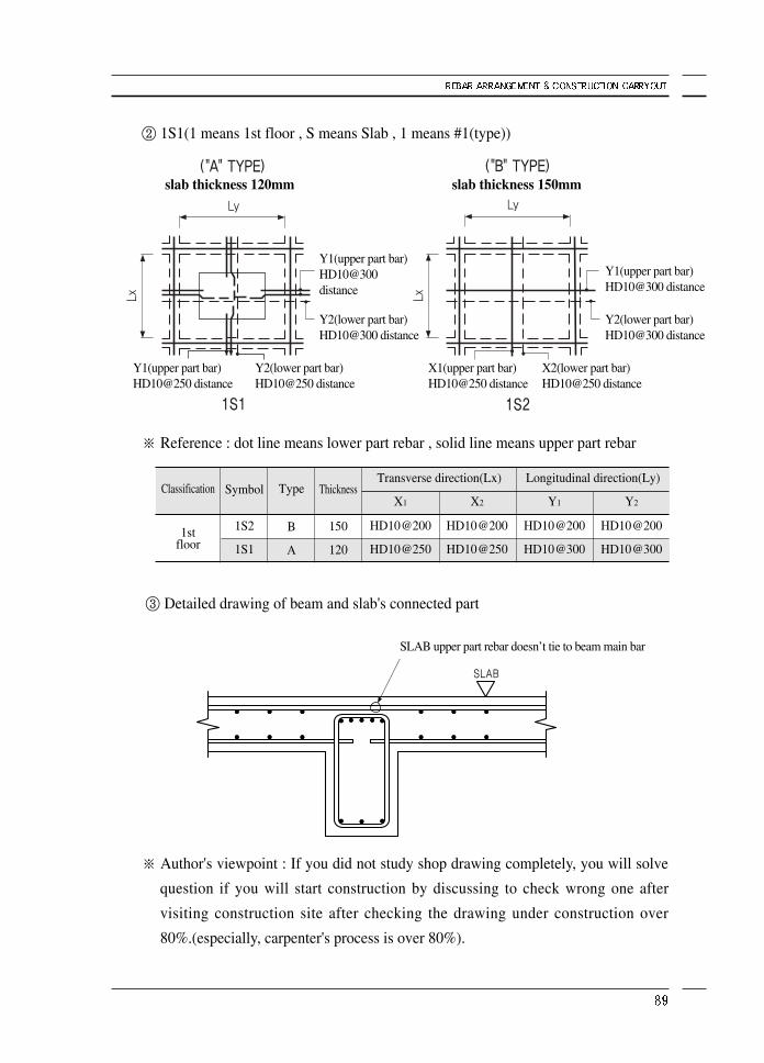
② 1S1(1 means 1st floor , S means Slab , 1 means #1(type))
※ Reference : dot line means lower part rebar , solid line means upper part rebar
③ Detailed drawing of beam and slab's connected part
※ Author's viewpoint : If you did not study shop drawing completely, you will solve
question if you will start construction by discussing to check wrong one after
visiting construction site after checking the drawing under construction over
80%.(especially, carpenter's process is over 80%).
Classification
1stfloor
Symbol
1S2
1S1
Type
B
A
Thickness
150
120
X1
HD10@200
HD10@250
Y1
HD10@200
HD10@300
X2
HD10@200
HD10@250
Y2
HD10@200
HD10@300
Longitudinal direction(Ly)Transverse direction(Lx)
slab thickness 120mm slab thickness 150mm
Y2(lower part bar)HD10@300 distance
Y2(lower part bar)HD10@300 distance
Y1(upper part bar)HD10@300 distance
Y2(lower part bar)HD10@250 distance
X2(lower part bar)HD10@250 distance
Y1(upper part bar)HD10@250 distance
X1(upper part bar)HD10@250 distance
SLAB upper part rebar doesn’t tie to beam main bar
Y1(upper part bar)HD10@300 distance
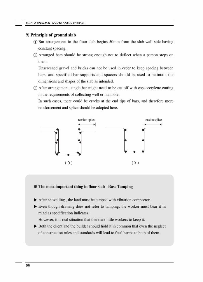
9) Principle of ground slab① Bar arrangement in the floor slab begins 50mm from the slab wall side having
constant spacing.
② Arranged bars should be strong enough not to deflect when a person steps on
them.
Unscreened gravel and bricks can not be used in order to keep spacing between
bars, and specified bar supports and spacers should be used to maintain the
dimensions and shapes of the slab as intended.
③ After arrangement, single bar might need to be cut off with oxy-acetylene cutting
in the requirements of collecting well or manhole.
In such cases, there could be cracks at the end tips of bars, and therefore more
reinforcement and splice should be adopted here.
※※ The most important thing in floor slab - Base Tamping
▶ After shovelling , the land must be tamped with vibration compactor.
▶ Even though drawing does not refer to tamping, the worker must bear it in
mind as specification indicates.
However, it is real situation that there are little workers to keep it.
▶ Both the client and the builder should hold it in common that even the neglect
of construction rules and standards will lead to fatal harms to both of them.
tension splice tension splice
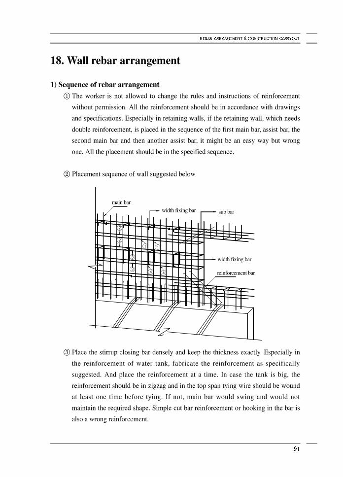
18. Wall rebar arrangement
1) Sequence of rebar arrangement① The worker is not allowed to change the rules and instructions of reinforcement
without permission. All the reinforcement should be in accordance with drawings
and specifications. Especially in retaining walls, if the retaining wall, which needs
double reinforcement, is placed in the sequence of the first main bar, assist bar, the
second main bar and then another assist bar, it might be an easy way but wrong
one. All the placement should be in the specified sequence.
② Placement sequence of wall suggested below
③ Place the stirrup closing bar densely and keep the thickness exactly. Especially in
the reinforcement of water tank, fabricate the reinforcement as specifically
suggested. And place the reinforcement at a time. In case the tank is big, the
reinforcement should be in zigzag and in the top span tying wire should be wound
at least one time before tying. If not, main bar would swing and would not
maintain the required shape. Simple cut bar reinforcement or hooking in the bar is
also a wrong reinforcement.
main barwidth fixing bar sub bar
reinforcement bar
width fixing bar
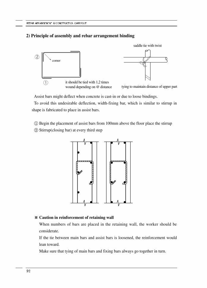
2) Principle of assembly and rebar arrangement binding
Assist bars might deflect when concrete is cast-in or due to loose bindings.
To avoid this undesirable deflection, width-fixing bar, which is similar to stirrup in
shape is fabricated to place in assist bars.
① Begin the placement of assist bars from 100mm above the floor place the stirrup
② Stirrup(closing bar) at every third step
※※ Caution in reinforcement of retaining wall
When numbers of bars are placed in the retaining wall, the worker should be
considerate.
If the tie between main bars and assist bars is loosened, the reinforcement would
lean toward.
Make sure that tying of main bars and fixing bars always go together in turn.
corner
saddle tie with twist
it should be tied with 1,2 timeswound depending on @ distance tying to maintain distance of upper part
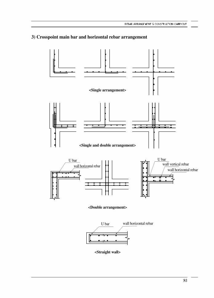
3) Crosspoint main bar and horizontal rebar arrangement
<Single arrangement>
<Single and double arrangement>
<Double arrangement>
<Straight wall>
wall horizontal rebarU bar
U bar
U barwall vertical rebar
wall horizontal rebar
wall horizontal rebar
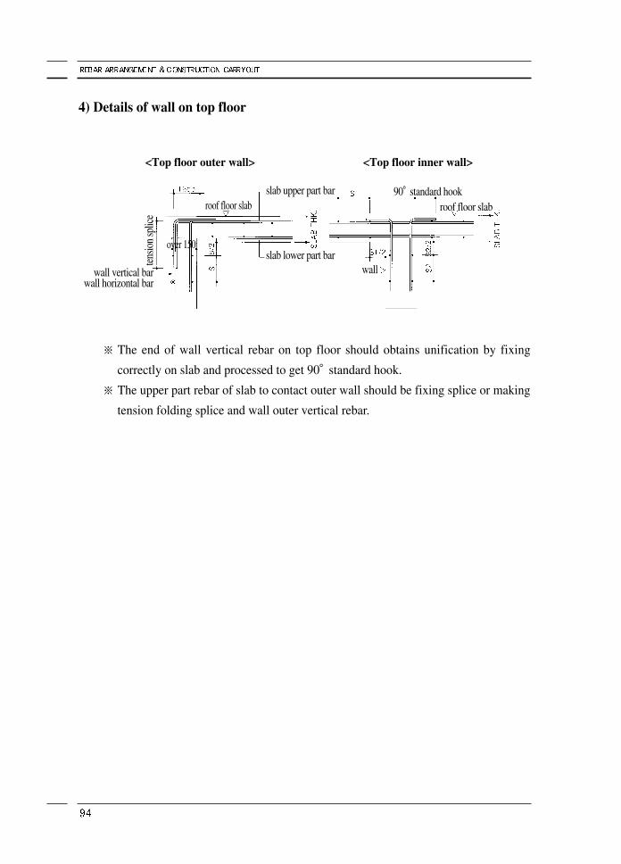
4) Details of wall on top floor
※ The end of wall vertical rebar on top floor should obtains unification by fixing
correctly on slab and processed to get 90°standard hook.
※ The upper part rebar of slab to contact outer wall should be fixing splice or making
tension folding splice and wall outer vertical rebar.
<Top floor outer wall> <Top floor inner wall>
90°standard hookroof floor slab
slab upper part bar
slab lower part bar
tensio
n sp
lice
over 150
wall vertical barwall horizontal bar
wall
roof floor slab
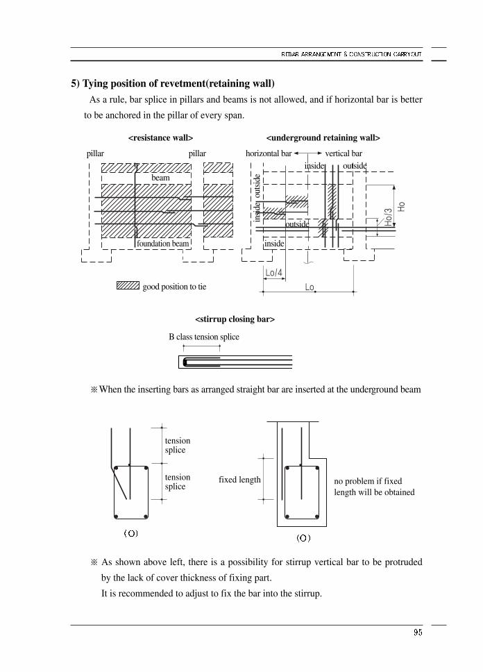
5) Tying position of revetment(retaining wall)As a rule, bar splice in pillars and beams is not allowed, and if horizontal bar is better
to be anchored in the pillar of every span.
※When the inserting bars as arranged straight bar are inserted at the underground beam
※ As shown above left, there is a possibility for stirrup vertical bar to be protruded
by the lack of cover thickness of fixing part.
It is recommended to adjust to fix the bar into the stirrup.
<resistance wall> <underground retaining wall>
<stirrup closing bar>
fixed length no problem if fixedlength will be obtained
tensionsplice
tensionsplice
pillar pillar horizontal bar vertical bar
good position to tie
B class tension splice
inside
inside
outside
outside
outs
ide
insi
de
foundation beam
beam
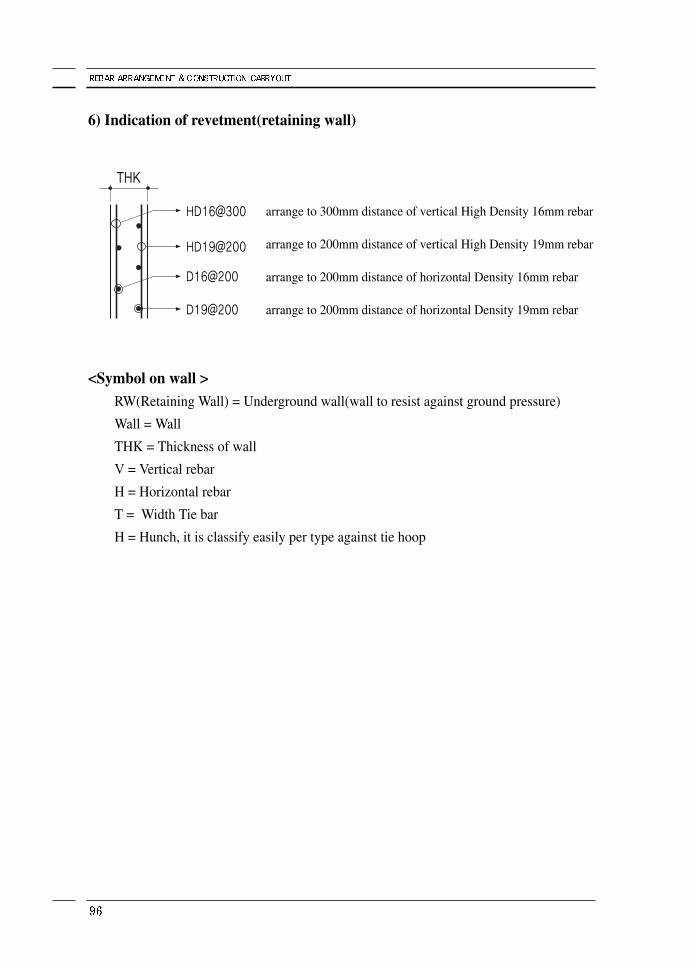
6) Indication of revetment(retaining wall)
arrange to 300mm distance of vertical High Density 16mm rebar
arrange to 200mm distance of vertical High Density 19mm rebar
arrange to 200mm distance of horizontal Density 16mm rebar
arrange to 200mm distance of horizontal Density 19mm rebar
<Symbol on wall >RW(Retaining Wall) = Underground wall(wall to resist against ground pressure)
Wall = Wall
THK = Thickness of wall
V = Vertical rebar
H = Horizontal rebar
T = Width Tie bar
H = Hunch, it is classify easily per type against tie hoop
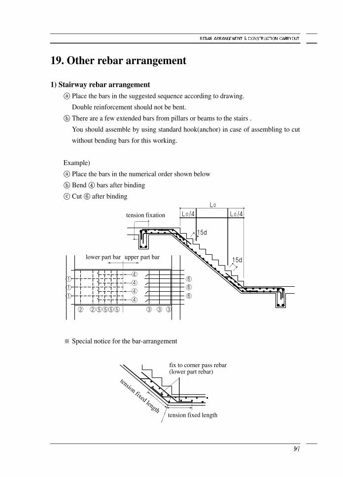
19. Other rebar arrangement
1) Stairway rebar arrangementⓐ Place the bars in the suggested sequence according to drawing.
Double reinforcement should not be bent.
ⓑ There are a few extended bars from pillars or beams to the stairs .
You should assemble by using standard hook(anchor) in case of assembling to cut
without bending bars for this working.
Example)
ⓐ Place the bars in the numerical order shown below
ⓑ Bend ④ bars after binding
ⓒ Cut ⑥ after binding
※ Special notice for the bar-arrangement
tension fixation
fix to corner pass rebar(lower part rebar)
tension fixed lengthtension fixed length
lower part bar upper part bar
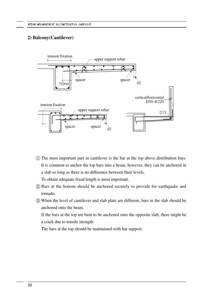
2) Balcony(Cantilever)
① The most important part in cantilever is the bar at the top above distribution bars.
It is common to anchor the top bars into a beam, however, they can be anchored in
a slab so long as there is no difference between their levels.
To obtain adequate fixed length is most important.
② Bars at the bottom should be anchored securely to provide for earthquake and
tornado.
③ When the level of cantilever and slab plate are different, bars in the slab should be
anchored onto the beam.
If the bars at the top are bent to be anchored onto the opposite slab, there might be
a crack due to tensile strength.
The bars at the top should be maintained with bar support.
tension fixation
tension fixation
vertical/horizontalD10-@220
upper support rebar
upper support rebar
spacer
spacer spacer
spacer
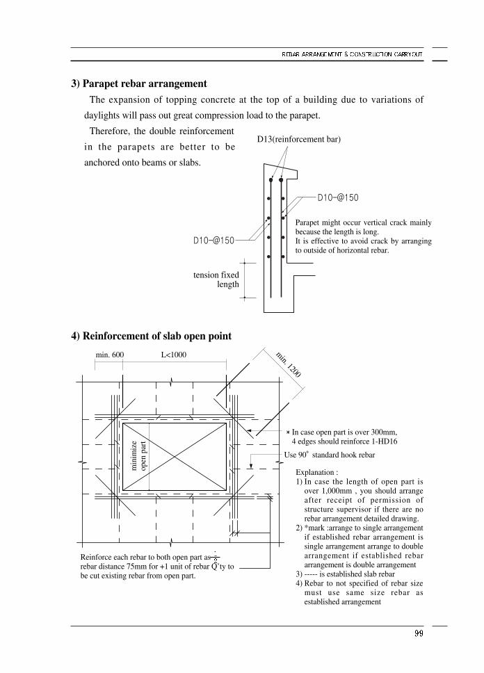
3) Parapet rebar arrangementThe expansion of topping concrete at the top of a building due to variations of
daylights will pass out great compression load to the parapet.
Therefore, the double reinforcement
in the parapets are better to be
anchored onto beams or slabs.
4) Reinforcement of slab open point
Explanation :1) In case the length of open part is
over 1,000mm , you should arrangeafter receipt of permission ofstructure supervisor if there are norebar arrangement detailed drawing.
2) *mark :arrange to single arrangementif established rebar arrangement issingle arrangement arrange to doublearrangement if established rebararrangement is double arrangement
3) ----- is established slab rebar4) Rebar to not specified of rebar size
must use same size rebar asestablished arrangement
Parapet might occur vertical crack mainlybecause the length is long. It is effective to avoid crack by arrangingto outside of horizontal rebar.
D13(reinforcement bar)
tension fixedlength
Use 90°standard hook rebar
In case open part is over 300mm,4 edges should reinforce 1-HD16
Reinforce each rebar to both open part asrebar distance 75mm for +1 unit of rebar Q’ty tobe cut existing rebar from open part.
min
imiz
eop
en p
art
L<1000min. 600 min. 1200
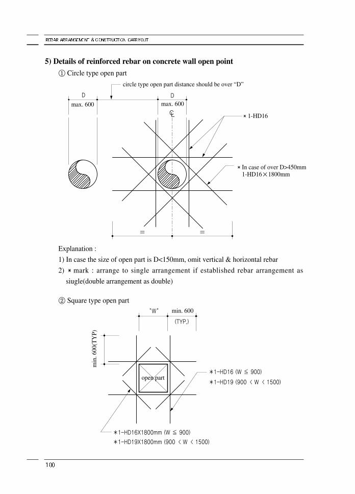
5) Details of reinforced rebar on concrete wall open point① Circle type open part
② Square type open part
Explanation :
1) In case the size of open part is D<150mm, omit vertical & horizontal rebar
2) mark : arrange to single arrangement if established rebar arrangement as
siugle(double arrangement as double)
circle type open part distance should be over “D”
max. 600 max. 600
In case of over D>450mm1-HD16×1800mm
1-HD16
min
. 600
(TY
P)
min. 600
open part
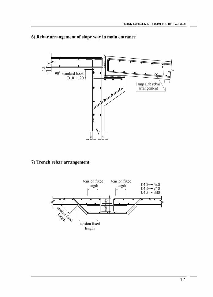
6) Rebar arrangement of slope way in main entrance
7) Trench rebar arrangement
90°standard hookD10→120
tension fixedlength
tension
fixed le
ngth
tension fixedlength
tension fixedlength
lamp slab rebararrangement
tension fixed
length
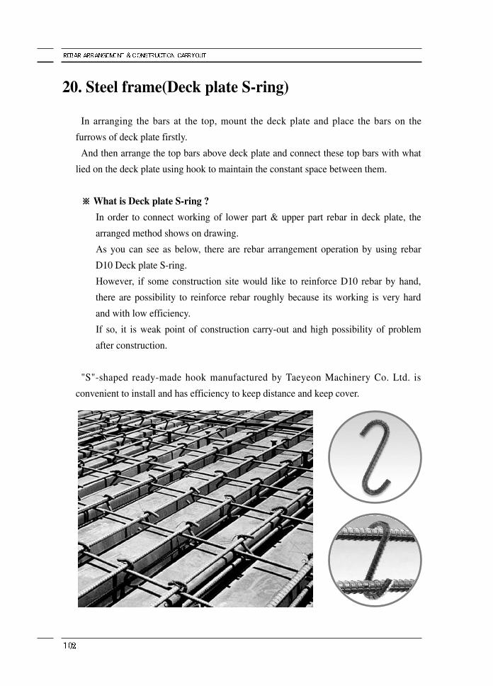
20. Steel frame(Deck plate S-ring)
In arranging the bars at the top, mount the deck plate and place the bars on the
furrows of deck plate firstly.
And then arrange the top bars above deck plate and connect these top bars with what
lied on the deck plate using hook to maintain the constant space between them.
※※ What is Deck plate S-ring ?
In order to connect working of lower part & upper part rebar in deck plate, the
arranged method shows on drawing.
As you can see as below, there are rebar arrangement operation by using rebar
D10 Deck plate S-ring.
However, if some construction site would like to reinforce D10 rebar by hand,
there are possibility to reinforce rebar roughly because its working is very hard
and with low efficiency.
If so, it is weak point of construction carry-out and high possibility of problem
after construction.
"S"-shaped ready-made hook manufactured by Taeyeon Machinery Co. Ltd. is
convenient to install and has efficiency to keep distance and keep cover.
21. Caution and consideration of construction carry-out
1) A man-dayThe amount of reinforcement that a skilled worker can place a day is, in case of slabs,
0.26acre ~ 0.33acre in area, about 500kg~700kg if converted in weight.
※ Daily work capacity(varies with working environment)
2) Weight of concrete① Specific weight of plain concrete(without reinforcement) is 2,300kg/1m3
② Specific weight of concrete with reinforcement in it is 2,400kg/1m3
③ Specific gravity of lightweight concrete with perlite or gas-foaming agent is only
0.6~1.2
3) Load and external forceIn construction, load and external force are critically important factors to be
considered.
Load is classified as fixed load and occupied load, where the former is the weight of
building itself and the later is the weight of people, furniture, equipment, etc..
Occupied load is classified again as long-term load and short-term load.
① The weight that 1m2 (square meter) sustains in long-term loading is
ⓐ Human or furniture 200kg/1m2
ⓑ Snow load 50kg/1m2
Classification
factory, school
apartment, house
<processing separately>
Q’ty(kg)
over 700
below 700
KR 130,000 per worker’s labor cost in 2006 year.
Classification
D10 stirrup, tie hoop
D13 stirrup
bending
<cutting separately>
Q’ty(kg)
600
800
5ton/1 person
② If weak at the long-term load : There might be a crack in walls or beams.
③ If weak at the short-term load : There might be not a crack but part breakage due
to external impact.
4) Crack and shrinkage① Crack of concrete is not simple problem to catch with several symptom such as
crack direction, etc but it is required to the inspection of professional.
Regularly, the crack under 0.3mm will be happened by dry shrinkage for
beginning vulcanization.
② Shrinkage of the building
If the length of the building is longer than 50,000mm, there is expansion or
shrinkage of the building, 10mm ~ 20mm, within temperature range from -18°C
~36°C.
(temperature difference×10-5×the length of building = difference length by
temperature gap(expansion or shrinkage))
③ In case of Korea, temperature difference is 54°C, from -18°C in winter to 36°C in
summer, According to the formula above, expansion in Korea is 27mm maximum
from 54°C×( ×50,000mm) = 27mm, hence there should be expansion
splice in some parts on high building & walls to prevent crack of the building.
5) Caution if construction work does① Distance of main bars against girder(beam)
ⓐ Beam plays an important part in a building, receiving the load from slabs and
passing it out to pillar.
Therefore the reinforcement in beams should be seriously taken into
consideration and accuracy.
Top bars, bottom bars, reinforcement bars, bent bars and middle bars are placed
in beams and distance of reinforcement should be more than 25mm or 1.25
times of the largest aggregate that is in the mixed concrete, over 1.5times
distance of rebar diameter.
ⓑ Splice length of top bar in beams should be required fixed length if it extends to
the center of column and therefore sustains tensile force.
Splice of the bottom bars in beams should be within from the end of beams,
where load is almost 0, and the top bars should avoid the end span of
beams.(min. rebar cost will be over 0.35%)
② Pillar
ⓐ Pillar also has important role to divide total weight and compression power of
building.
Distance of main bar also arrange bar fairly, distance per rebar and rebar will be
over 40mm or over 1.5times of rebar using.
ⓑ The minimum size of column is more than 200mm and cross sectional area
should be more than 600cm2
ⓒ Splice length applies B class splice length.
6) Reinforcement to prevent shrinkage of wallThe building might get shrinkage on building by the expansion of temperature in day
or the down of temperature in night.
Rebar concrete has expansion or shrinkage, and so there are possibility of unexpected
rebar.
Therefore, the point of crack possibility must reinforce outer wall without open part.
Arrangement direction of correct reinforced bar, it can be checked crack correctly, it is
principle to arrange bars vertically against crack direction.
If there are crack on both edges of wall by the expansion of roof, reinforced bar is
principle to arrange bars vertically against crack direction and you reinforce the
reinforced bar of highest wall to outer top pillar & retaining wall of building.
The expansion ratio of roof will be bigger toward outside and very small roof on
center of building.
Also, 1st floor contacts ground do not effected of the influence of temperature.
Therefore , the part of highest influence by expansion & shrinkage of roof is outside
wall and there are expecting many cracks.
Without marking on shop drawing, you must arrange construction with your sincerity
with our experiences.
7) CleaningIt is better to install concrete after cleaning always before installing concrete.
When you checking construction site, there are many other materials to decline the
quality of concrete such as soil, sawdust, trash.
You must delete it inevitably.
After concrete job, you must break concrete of ground and brush concrete on rebar
with hammer drill, wire brush , hammer on next floor splice part, wall, pillar.
8) Problem if oxy-acetylene cutting does
① Don't use the oxygen arc cutter near the pile of unused bars.
If you use the oxygen arc cutter near the piled bars, high heat from cutting rod will
be transferred to unused bars causing thermal deformation or unexpected failure.
Automated cutting machine and bending machine are recommended.
② Oxygen arc cutter will drop tensile strength of the bar, which is critically important
to the reinforcement of the structure, and there might be problems in structural
safety.
③ Manual bar cutters have been normally used in the construction sites so far.
However, in order to increase the effectiveness and ensure perfectness, automated
cutting machines and bending machines are highly recommended.
<Reference>
Rebar arrangement should arranged by the shop drawing.
Technicians must increase the ability to see shop drawing if it is the recent drawing by
limit strength plan method.
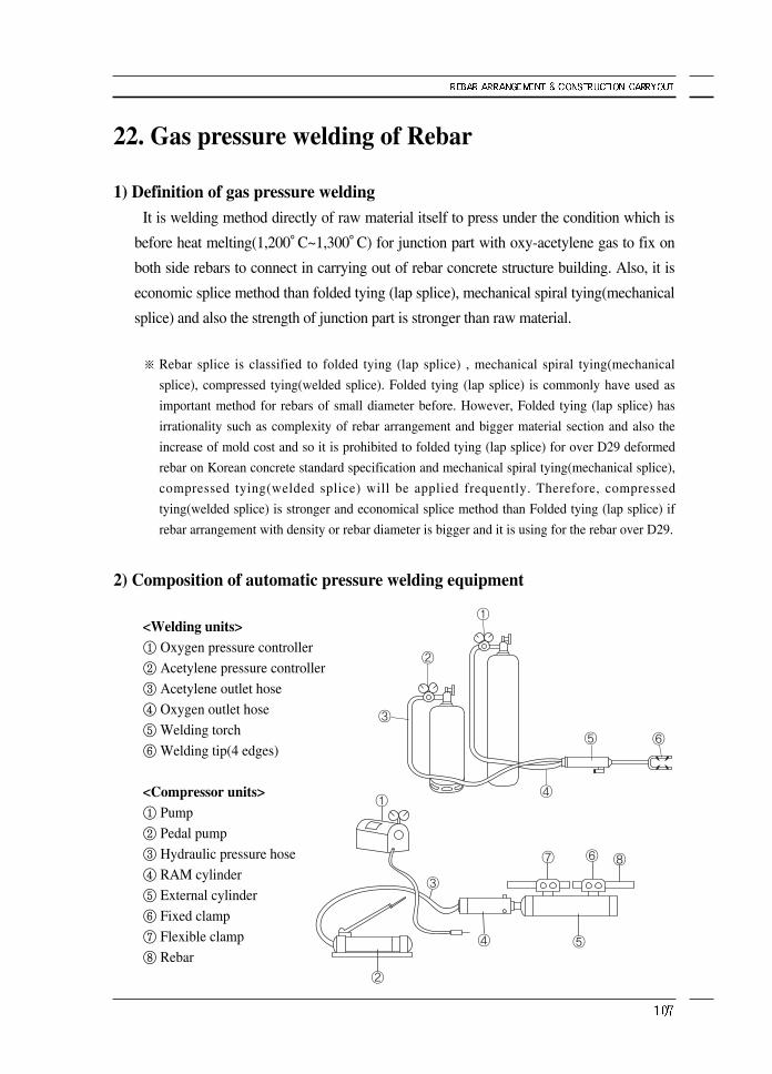
22. Gas pressure welding of Rebar
1) Definition of gas pressure weldingIt is welding method directly of raw material itself to press under the condition which is
before heat melting(1,200°C~1,300°C) for junction part with oxy-acetylene gas to fix on
both side rebars to connect in carrying out of rebar concrete structure building. Also, it is
economic splice method than folded tying (lap splice), mechanical spiral tying(mechanical
splice) and also the strength of junction part is stronger than raw material.
※ Rebar splice is classified to folded tying (lap splice) , mechanical spiral tying(mechanical
splice), compressed tying(welded splice). Folded tying (lap splice) is commonly have used as
important method for rebars of small diameter before. However, Folded tying (lap splice) has
irrationality such as complexity of rebar arrangement and bigger material section and also the
increase of mold cost and so it is prohibited to folded tying (lap splice) for over D29 deformed
rebar on Korean concrete standard specification and mechanical spiral tying(mechanical splice),
compressed tying(welded splice) will be applied frequently. Therefore, compressed
tying(welded splice) is stronger and economical splice method than Folded tying (lap splice) if
rebar arrangement with density or rebar diameter is bigger and it is using for the rebar over D29.
2) Composition of automatic pressure welding equipment
<Welding units>① Oxygen pressure controller
② Acetylene pressure controller
③ Acetylene outlet hose
④ Oxygen outlet hose
⑤ Welding torch
⑥ Welding tip(4 edges)
<Compressor units>① Pump
② Pedal pump
③ Hydraulic pressure hose
④ RAM cylinder
⑤ External cylinder
⑥ Fixed clamp
⑦ Flexible clamp
⑧ Rebar
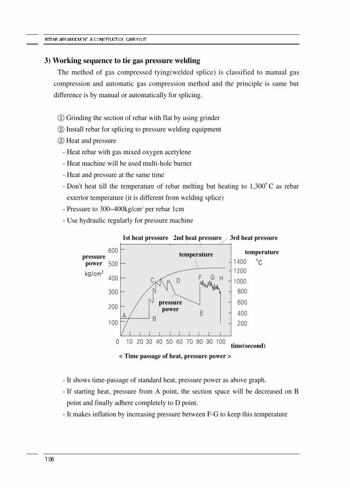
3) Working sequence to tie gas pressure welding The method of gas compressed tying(welded splice) is classified to manual gas
compression and automatic gas compression method and the principle is same but
difference is by manual or automatically for splicing.
① Grinding the section of rebar with flat by using grinder
② Install rebar for splicing to pressure welding equipment
③ Heat and pressure
- Heat rebar with gas mixed oxygen acetylene
- Heat machine will be used multi-hole burner
- Heat and pressure at the same time
- Don't heat till the temperature of rebar melting but heating to 1,300°C as rebar
exterior temperature (it is different from welding splice)
- Pressure to 300~400kg/cm2 per rebar 1cm
- Use hydraulic regularly for pressure machine
- It shows time-passage of standard heat, pressure power as above graph.
- If starting heat, pressure from A point, the section space will be decreased on B
point and finally adhere completely to D point.
- It makes inflation by increasing pressure between F-G to keep this temperature
< Time passage of heat, pressure power >
1st heat pressure
pressurepower
pressurepower
temperature temperature
time(second)
2nd heat pressure 3rd heat pressure
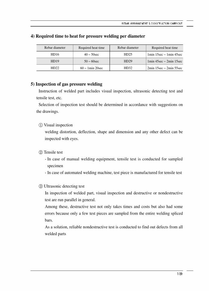
4) Required time to heat for pressure welding per diameter
5) Inspection of gas pressure weldingInstruction of welded part includes visual inspection, ultrasonic detecting test and
tensile test, etc.
Selection of inspection test should be determined in accordance with suggestions on
the drawings.
① Visual inspection
welding distortion, deflection, shape and dimension and any other defect can be
inspected with eyes.
② Tensile test
- In case of manual welding equipment, tensile test is conducted for sampled
specimen
- In case of automated welding machine, test piece is manufactured for tensile test
③ Ultrasonic detecting test
In inspection of welded part, visual inspection and destructive or nondestructive
test are run parallel in general.
Among these, destructive test not only takes times and costs but also had some
errors because only a few test pieces are sampled from the entire welding spliced
bars.
As a solution, reliable nondestructive test is conducted to find out defects from all
welded parts
Required heat time
40 ~ 50sec
50 ~ 60sec
60 ~ 1min 20sec
Rebar diameter
HD16
HD19
HD22
Required heat time
1min 15sec ~ 1min 45sec
1min 45sec ~ 2min 15sec
2min 15sec ~ 2min 55sec
Rebar diameter
HD25
HD29
HD32
6) Caution if pressure welding works
① The builder will get the admission of person in charge to select gas pressure
welding worker.
② You must check and maintenance inevitably before working for oxygen , acetylene
instrument and protect it from direct rays.
③ The compression section should be decreased by cutting of plane after deleting oil,
paint, cement piece, etc but to be cut the neighbor surface by grinder.
④ The final pressure of rebar discharge direction should be over 300kgf/cm2 per
dimension.
The diameter of compression protrusion part should be over 1.4times of rebar
diameter and diameter of compression protrusion part should over 1.2times and
the form should be smooth.
But , it is followed by in case it is fixed by shop drawing separately.
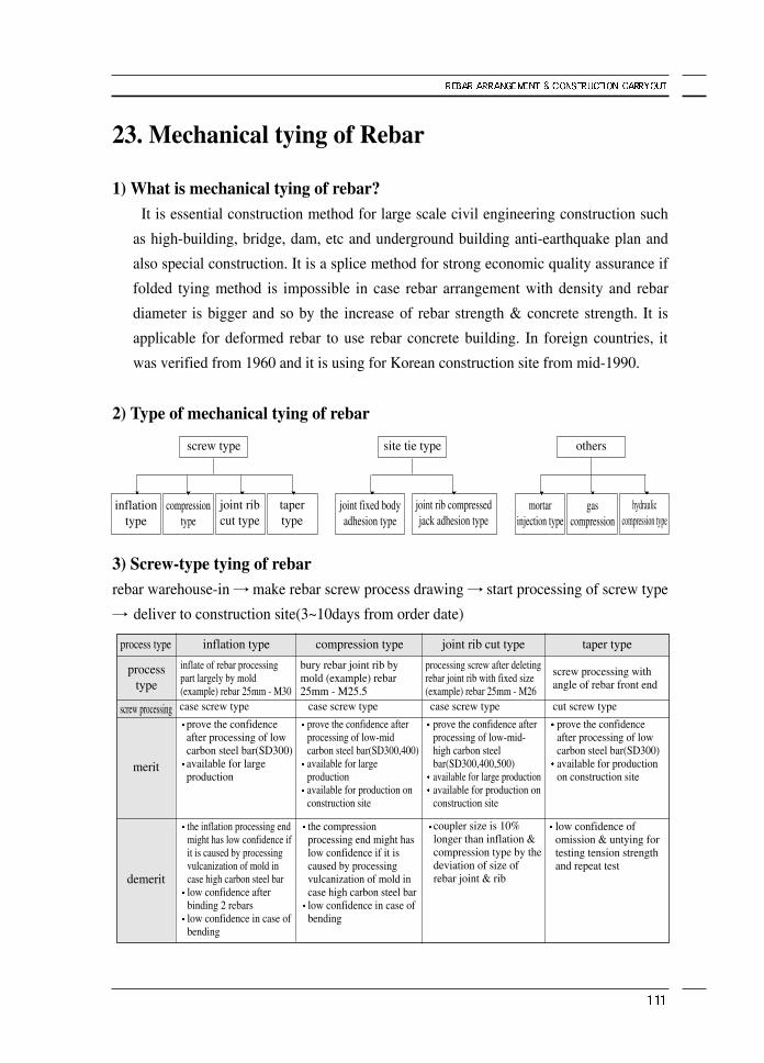
23. Mechanical tying of Rebar
1) What is mechanical tying of rebar?It is essential construction method for large scale civil engineering construction such
as high-building, bridge, dam, etc and underground building anti-earthquake plan and
also special construction. It is a splice method for strong economic quality assurance if
folded tying method is impossible in case rebar arrangement with density and rebar
diameter is bigger and so by the increase of rebar strength & concrete strength. It is
applicable for deformed rebar to use rebar concrete building. In foreign countries, it
was verified from 1960 and it is using for Korean construction site from mid-1990.
2) Type of mechanical tying of rebar
3) Screw-type tying of rebarrebar warehouse-in → make rebar screw process drawing → start processing of screw type
→ deliver to construction site(3~10days from order date)
screw type
inflationtype
compressiontype
joint ribcut type
tapertype
others
mortarinjection type
gascompression
hydrauliccompression type
site tie type
joint fixed bodyadhesion type
joint rib compressedjack adhesion type
processtype
process type inflation type compression type joint rib cut type taper type
inflate of rebar processingpart largely by mold(example) rebar 25mm - M30case screw type
bury rebar joint rib bymold (example) rebar25mm - M25.5
processing screw after deletingrebar joint rib with fixed size(example) rebar 25mm - M26
screw processing withangle of rebar front end
prove the confidenceafter processing of lowcarbon steel bar(SD300)available for largeproduction
prove the confidence afterprocessing of low-midcarbon steel bar(SD300,400)available for largeproductionavailable for production onconstruction site
prove the confidence afterprocessing of low-mid-high carbon steelbar(SD300,400,500)available for large productionavailable for production onconstruction site
prove the confidenceafter processing of lowcarbon steel bar(SD300)available for productionon construction site
the inflation processing endmight has low confidence ifit is caused by processingvulcanization of mold incase high carbon steel barlow confidence afterbinding 2 rebarslow confidence in case ofbending
the compressionprocessing end might haslow confidence if it iscaused by processingvulcanization of mold incase high carbon steel barlow confidence in case ofbending
coupler size is 10%longer than inflation &compression type by thedeviation of size ofrebar joint & rib
low confidence ofomission & untying fortesting tension strengthand repeat test
case screw type case screw type cut screw typescrew processing
merit
demerit
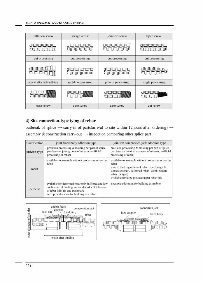
4) Site connection-type tying of rebaroutbreak of splice → carry-in of parts(arrival to site within 12hours after ordering) →assembly & construction carry-out → inspection comparing other splice part
process type
classification joint fixed body adhesion type joint rib compressed jack adhesion typeprecision processing & molding per part of splicepart base on joint groove of rebar(no artificialprocessing of rebar)
precision processing & molding per part of splicepart base on nominal diameter of rebar(no artificialprocessing of rebar)
available to assemble without processing screw onrebar
available to assemble without processing screw onrebarease to bind regardless of rebar type(foreign &domestic rebar , deformed rebar , comb-patternrebar , X type)available for large production per rebar title
need pre-education for building assembleravailable for deformed rebar only in Korea and lowconfidence of binding in case disorder of toleranceof rebar joint rib and trademarkneed pre-education for building assembler
merit
demerit
inflation screw swage screw joint-rib screw taper screw
cut processing cut processing cut processing cut processing
pre-cut after mold inflation mold compression pre-cut processing angle processing
case screw case screw case screw cut screw
lock nut fixed pincompression jack
lock coupler
connection jack
fixed bodyrebar
length after bindingoute
r dia
met
er o
f cou
pler
double facedcoupler
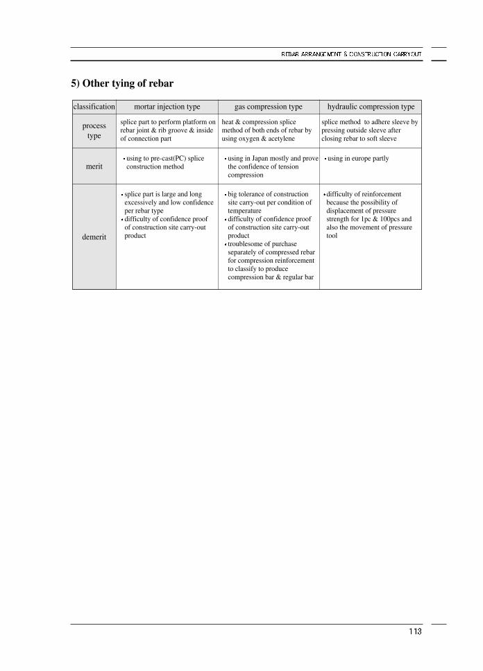
5) Other tying of rebar
process type
classification mortar injection type gas compression type hydraulic compression type
splice part to perform platform onrebar joint & rib groove & insideof connection part
heat & compression splicemethod of both ends of rebar byusing oxygen & acetylene
splice method to adhere sleeve bypressing outside sleeve afterclosing rebar to soft sleeve
using to pre-cast(PC) spliceconstruction method
using in Japan mostly and provethe confidence of tensioncompression
using in europe partly
splice part is large and longexcessively and low confidenceper rebar typedifficulty of confidence proofof construction site carry-outproduct
big tolerance of constructionsite carry-out per condition oftemperaturedifficulty of confidence proofof construction site carry-outproducttroublesome of purchaseseparately of compressed rebarfor compression reinforcementto classify to producecompression bar & regular bar
difficulty of reinforcementbecause the possibility ofdisplacement of pressurestrength for 1pc & 100pcs andalso the movement of pressuretool
merit
demerit