GNOM - Axle load sensor for spring suspension, 2 axles vehicle
REAR SUSPENSION AND AXLES
CONTENTS
page page
AXLE NOISE/VIBRATION DIAGNOSIS . . . . . . . . . 6GENERAL INFORMATION . . . . . . . . . . . . . . . . . . 1MODEL 35 AXLE . . . . . . . . . . . . . . . . . . . . . . . . 10
REAR SUSPENSION . . . . . . . . . . . . . . . . . . . . . . 3TORQUE SPECIFICATIONS . . . . . . . . . . . . . . . . 32TRAC-LOK DIFFERENTIAL . . . . . . . . . . . . . . . . 27
GENERAL INFORMATION
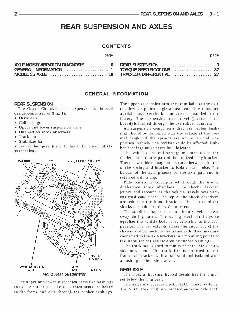
REAR SUSPENSIONThe Grand Cherokee rear suspension is link/coil
design comprised of (Fig. 1);• Drive axle• Coil springs• Upper and lower suspension arms• Dual-action shock absorbers• Track bar• Stabilizer bar• Jounce bumpers (used to limit the travel of thesuspension)
The upper and lower suspension arms use bushingsto isolate road noise. The suspension arms are boltedto the frame and axle through the rubber bushings.
The upper suspension arm uses cam bolts at the axleto allow for pinion angle adjustment. The cams areavailable as a service kit and are not installed at thefactory. The suspension arm travel (jounce or re-bound) is limited through the use rubber bumpers.
All suspension components that use rubber bush-ings should be tightened with the vehicle at the nor-mal height. If the springs are not at normal rideposition, vehicle ride comfort could be affected. Rub-ber bushings must never be lubricated.
The vehicles use coil springs mounted up in thefender shield that is part of the unitized body bracket.There is a rubber doughnut isolator between the topof the spring and bracket to isolate road noise. Thebottom of the spring seats on the axle pad and isretained with a clip.
Ride control is accomplished through the use ofdual-action shock absorbers. The shocks dampenjounce and rebound as the vehicle travels over vari-ous road conditions. The top of the shock absorbersare bolted to the frame brackets. The bottom of theshocks are bolted to the axle brackets.
The stabilizer bar is used to minimize vehicle rearsway during turns. The spring steel bar helps toequalize the vehicle body in relationship to the sus-pension. The bar extends across the underside of thechassis and connects to the frame rails. The links areconnected to the axle brackets. All mounting points ofthe stabilizer bar are isolated by rubber bushings.
The track bar is used to minimize rear axle side-to-side movement. The track bar is attached to theframe rail bracket with a ball stud and isolated witha bushing at the axle bracket.
REAR AXLEThe integral housing, hypoid design has the pinion
set below the ring gear.The axles are equipped with A.B.S. brake systems.
The A.B.S. tone rings are pressed onto the axle shaft
Fig. 1 Rear Suspension
Z REAR SUSPENSION AND AXLES 3 - 1
near the hub flange. For additional information onthe A.B.S. system refer to Group 5, Brakes.
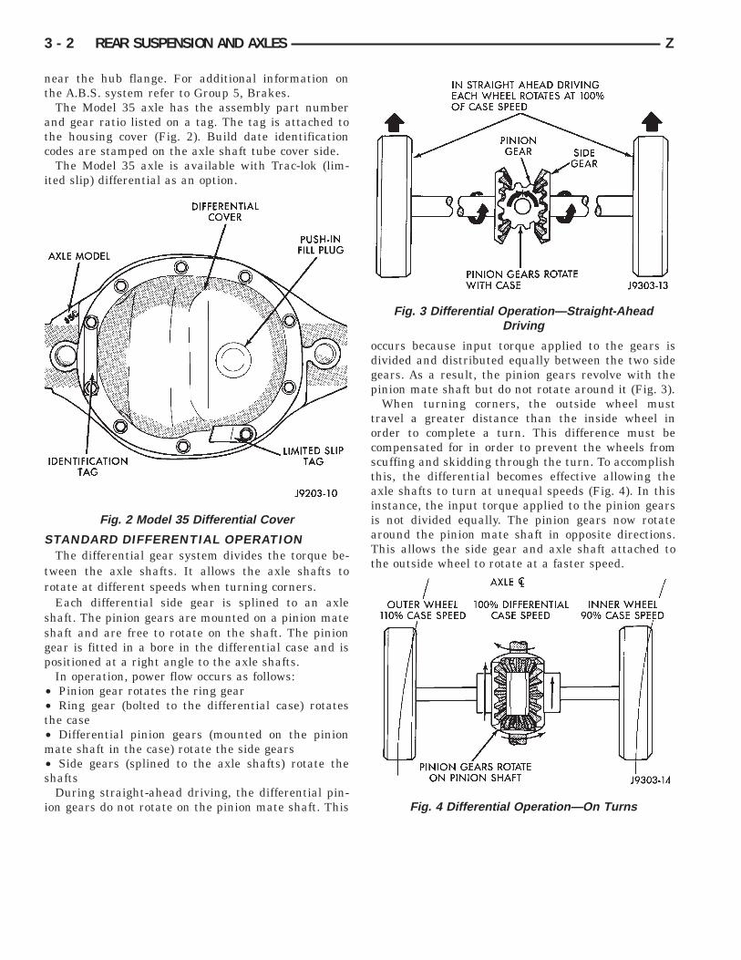
The Model 35 axle has the assembly part numberand gear ratio listed on a tag. The tag is attached tothe housing cover (Fig. 2). Build date identificationcodes are stamped on the axle shaft tube cover side.
The Model 35 axle is available with Trac-lok (lim-ited slip) differential as an option.
STANDARD DIFFERENTIAL OPERATIONThe differential gear system divides the torque be-
tween the axle shafts. It allows the axle shafts torotate at different speeds when turning corners.
Each differential side gear is splined to an axleshaft. The pinion gears are mounted on a pinion mateshaft and are free to rotate on the shaft. The piniongear is fitted in a bore in the differential case and ispositioned at a right angle to the axle shafts.
In operation, power flow occurs as follows:• Pinion gear rotates the ring gear• Ring gear (bolted to the differential case) rotatesthe case• Differential pinion gears (mounted on the pinionmate shaft in the case) rotate the side gears• Side gears (splined to the axle shafts) rotate theshafts
During straight-ahead driving, the differential pin-ion gears do not rotate on the pinion mate shaft. This
occurs because input torque applied to the gears isdivided and distributed equally between the two sidegears. As a result, the pinion gears revolve with thepinion mate shaft but do not rotate around it (Fig. 3).
When turning corners, the outside wheel musttravel a greater distance than the inside wheel inorder to complete a turn. This difference must becompensated for in order to prevent the wheels fromscuffing and skidding through the turn. To accomplishthis, the differential becomes effective allowing theaxle shafts to turn at unequal speeds (Fig. 4). In thisinstance, the input torque applied to the pinion gearsis not divided equally. The pinion gears now rotatearound the pinion mate shaft in opposite directions.This allows the side gear and axle shaft attached tothe outside wheel to rotate at a faster speed.
Fig. 2 Model 35 Differential Cover
Fig. 3 Differential Operation—Straight-AheadDriving
Fig. 4 Differential Operation—On Turns
3 - 2 REAR SUSPENSION AND AXLES Z

REAR SUSPENSION
INDEX
page page
Coil Spring . . . . . . . . . . . . . . . . . . . . . . . . . . . . . . 4Lower Suspension Arm . . . . . . . . . . . . . . . . . . . . . 4Service Information . . . . . . . . . . . . . . . . . . . . . . . . 3Shock Absorber . . . . . . . . . . . . . . . . . . . . . . . . . . . 4
Spring and Shock Diagnosis . . . . . . . . . . . . . . . . . . 4Stabilizer Bar . . . . . . . . . . . . . . . . . . . . . . . . . . . . . 3Track Bar . . . . . . . . . . . . . . . . . . . . . . . . . . . . . . . 3Upper Suspension Arm . . . . . . . . . . . . . . . . . . . . . 4
SERVICE INFORMATION
CAUTION: All suspension components that use rub-ber bushings should be tightened with the vehicle atthe normal height. Have the springs supporting theweight of vehicle when fasteners are torqued. If thesprings are not at their normal ride position, vehicleride comfort could be affected. Rubber bushingsmust never be lubricated.
TRACK BAR
REMOVAL(1) Raise and support the vehicle.(2) Remove the bolt and nut from the frame rail
bracket (Fig. 1).
(3) Remove the bolt from the axle tube bracket(Fig. 1). Remove the track bar.
INSTALLATION(1) Install the track bar to the axle bracket and
install the bolt (Fig. 1).(2) It may be necessary to pry the axle assembly
over to install the track bar. Install the track bar tothe frame rail bracket. Loosely install the bolt andflag nut (Fig. 1).
(3) Remove the supports and lower the vehicle.(4) Tighten the bolt at the axle shaft tube bracket
to 100 NIm (74 ft. lbs.) torque.(5) Tighten the nut at the frame rail to 100 NIm
(74 ft. lbs.) torque.
STABILIZER BAR
REMOVAL(1) Raise and support the vehicle. Remove one
wheel and tire.(2) Disconnect the stabilizer bar links from the axle
brackets (Fig. 2).(3) Lower the exhaust by disconnecting the muffler
and tail pipe hangers.(4) Disconnect the stabilizer bar from the links.(5) Disconnect the stabilizer bar clamps from the
frame rails. Remove the stabilizer bar.
Fig. 1 Rear Track Bar
Fig. 2 Rear Stabilizer Bar
Z REAR SUSPENSION AND AXLES 3 - 3

INSTALLATION(1) Position the stabilizer bar on the frame rail and
install the clamps and bolts. Ensure the bar is cen-tered with equal spacing on both sides. Tighten thebolts to 54 NIm (40 ft. lbs.).
(2) Install the links and grommets onto the stabi-lizer bar and axle brackets (Fig. 2). Install the nutsand tighten to 36 NIm (27 ft. lbs.) torque.
(3) Connect the muffler and tail pipe to their hang-ers.
(4) Install the wheel and tire.
UPPER SUSPENSION ARM
REMOVAL(1) Raise and support the vehicle.(2) Remove the upper suspension arm nut and bolt
at the axle bracket (Fig. 3). Remove the ABS wirebracket from the arm.
(3) Remove the nut and bolt (Fig. 3) at the framerail and remove the upper suspension arm.
INSTALLATION(1) Position the upper suspension arm at the axle
and frame rail (Fig. 3).(2) Install the bolts and finger tighten the nuts
(Fig. 3). Install the ABS wire bracket onto the arm.(3) Remove the supports and lower the vehicle.(4) Tighten the nut at the axle bracket to 75 NIm
(55 ft. lbs.) torque.(5) Tighten the nut at the frame rail to 75 NIm (55
ft. lbs.) torque.
LOWER SUSPENSION ARM
REMOVAL(1) Raise and support the vehicle.(2) Remove the lower suspension arm nut and bolt
at the axle bracket (Fig. 3).(3) Remove the nut and bolt (Fig. 3) at the frame
rail and remove the lower suspension arm.
INSTALLATION(1) Position the lower suspension arm at the axle
bracket and frame rail bracket (Fig. 3).(2) Install the bolts and finger tighten the nuts
(Fig. 3).(3) Remove the supports and lower the vehicle.(4) Tighten the nut at the axle bracket to 177 NIm
(130 ft. lbs.) torque.(5) Tighten the bolt at the frame rail to 177 NIm
(130 ft. lbs.) torque.
SPRING AND SHOCK DIAGNOSISA squeak noise from the shock absorber can be
produced if movement between the rubber bushingsand the metal occurs. This noise can usually bestopped by tightening the attaching nuts. If thesqueak noise persists, inspect for damaged and wornbushings, and attaching components. Repair as neces-sary if any of these conditions exist.
The shock absorbers are not refillable or adjustable.If a malfunction occurs, the shock absorber must bereplaced. To test a shock absorber, hold it in an up-right position and force the piston into and out of thecylinder four or five times. The action throughouteach stroke should be smooth and even.
SHOCK ABSORBER
REMOVAL(1) Remove the upper nut and retainer from the
frame rail stud (Fig. 4).(2) Remove the lower nuts and bolts from the axle
bracket. Remove the shock absorber.
INSTALLATION(1) Install the shock absorber on the upper frame
rail stud. Install the shock absorber on the axlebracket (Fig. 4).
(2) Install the retainer and nut on the stud.Tighten the upper nut to 70 NIm (52 ft. lbs.) torque.
(3) Tighten the lower nut to 92 NIm (68 ft. lbs.)torque.
COIL SPRING
REMOVAL(1) Raise and support the vehicle. Position a hy-
draulic jack under the axle to support it.(2) Disconnect the stabilizer bar link and shock
absorber from the axle bracket.
Fig. 3 Upper and Lower Suspension Arms
3 - 4 REAR SUSPENSION AND AXLES Z

(3) Disconnect the track bar from the frame railbracket.
(4) Lower the axle until the spring is free from theupper mount seat. Remove the coil spring clip screw(Fig. 4) and remove the spring.
INSTALLATION(1) Position the coil spring on the axle pad. Install
the spring clip and screw (Fig. 4). Tighten the screwto 22 NIm (16 ft. lbs.) torque.
(2) Raise the axle into position until the springseats in the upper mount.
(3) Connect the stabilizer bar links and shock ab-sorbers to the axle bracket. Connect the track bar tothe frame rail bracket.
(4) Remove the supports and lower the vehicle.
Fig. 4 Rear Coil Spring & Shock Absorber
Z REAR SUSPENSION AND AXLES 3 - 5

AXLE NOISE/VIBRATION DIAGNOSIS
INDEX
page page
Driveline Snap . . . . . . . . . . . . . . . . . . . . . . . . . . . . 7Gear and Bearing Noise . . . . . . . . . . . . . . . . . . . . . 6General Information . . . . . . . . . . . . . . . . . . . . . . . . 6Limited Slip Differential . . . . . . . . . . . . . . . . . . . . . . 7
Low Speed Knock . . . . . . . . . . . . . . . . . . . . . . . . . 7Rear Axle Alignment . . . . . . . . . . . . . . . . . . . . . . . . 7Vibration . . . . . . . . . . . . . . . . . . . . . . . . . . . . . . . . 7
GENERAL INFORMATIONAxle bearing problem conditions are usually caused
by:• Insufficient or incorrect lubricant• Foreign matter/water contamination• Incorrect bearing preload torque adjustment
When serviced, the bearings must be cleaned thor-oughly. They should be dried with lint-free shop tow-els. Never dry bearings with compressed air.This will overheat them and brinell the bearingsurfaces. This will result in noisy operation af-ter repair.
Axle gear problem conditions are usually the resultof:• Insufficient lubrication• Incorrect or contaminated lubricant• Overloading (excessive engine torque)• Incorrect clearance or backlash adjustment
Insufficient lubrication is usually the result of ahousing cover leak. It can also be from worn axleshaft or pinion gear seals. Check for cracks or porousareas in the housing or tubes.
Using the wrong lubricant will cause overheatingand gear failure. Gear tooth cracking and bearingspalling are indicators of this.
Axle component breakage is most often the resultof:• Severe overloading• Insufficient lubricant• Incorrect lubricant• Improperly tightened components
Common causes of overloading is from full-throttleacceleration. Overloading happens when towingheavier-than-recommended loads. Component break-age can occur when the wheels are spun excessively.Insufficient or incorrect lubricants contribute tobreakage through overheating. Loose differential com-ponents can also cause breakage.
Incorrect bearing preload or gear backlash will notresult in component breakage. Mis-adjustment willproduce enough noise to cause service repair before afailure occurs. If a mis-adjustment condition is notcorrected, component failure can result.
GEAR AND BEARING NOISE
GEAR NOISEAxle gear noise can be caused by insufficient lubri-
cant. Incorrect backlash, tooth contact, orworn/damaged gears can cause noise.
Gear noise usually happens at a specific speedrange. The range is 30 to 40 mph, or above 50 mph.The noise can also occur during a specific type ofdriving condition. These conditions are acceleration,deceleration, coast, or constant load.
When road testing, accelerate the vehicle to thespeed range where the noise is the greatest. Shiftout-of-gear and coast through the peak-noise range. Ifthe noise stops or changes greatly, check for insuffi-cient lubricant. Incorrect ring gear backlash, or geardamage can cause noise changes.
Differential side and pinion gears can be checked byturning the vehicle. They usually do not cause noisein straight-ahead driving. These gears are loaded dur-ing vehicle turns. If noise does occur during vehicleturns, the side or pinion gears could be worn ordamaged. A worn pinion gear mate shaft can alsocause a snapping or a knocking noise.
BEARING NOISEThe axle shaft, differential and pinion gear bearings
can all produce noise when worn or damaged. Bearingnoise can be either a whining, or a growling sound.
Pinion gear bearings have a constant-pitch noise.This noise changes only with vehicle speed. Pinionbearing noise will be higher because it rotates at afaster rate. Drive the vehicle and load the differential.If bearing noise occurs the pinion rear bearing is thesource of the noise. If the bearing noise is heardduring a coast, front bearing is the source.
Worn, damaged differential bearings usually pro-duce a low pitch noise. Differential bearing noise issimilar to pinion bearing. The pitch of differentialbearing noise is also constant and varies only withvehicle speed.
Axle shaft bearings produce noise and vibrationwhen worn or damaged. The noise generally changeswhen the bearings are loaded. Road test the vehicle.Turn the vehicle sharply to the left and to the right.This will load the bearings and change the noise
3 - 6 REAR SUSPENSION AND AXLES Z

level. Where axle bearing damage is slight, the noiseis usually not noticeable at speeds above 30 mph.
LOW SPEED KNOCKLow speed knock is generally caused by a worn
U-joint or by worn side-gear thrust washers. A wornpinion gear shaft bore will also cause low speedknock.
VIBRATIONVibration at the rear of the vehicle is usually
caused by a:• Damaged drive shaft• Missing drive shaft balance weight• Worn, out-of-balance wheels• Loose wheel lug nuts• Worn U-joint• Loose spring U-bolts• Loose/broken springs• Damaged axle shaft bearings• Loose pinion gear nut• Excessive pinion yoke run out• Bent axle shaft
Check for loose or damaged front-end componentsor engine/transmission mounts. These componentscan contribute to what appears to be a rear-end vibra-tion. Do not overlook engine accessories, brackets anddrive belts.
All driveline components should be examined beforestarting any repair.
Refer to Group 22, Wheels and Tires for additionalinformation.
DRIVELINE SNAPA snap or clunk noise when the vehicle is shifted
into gear (or the clutch engaged), can be caused by:• High engine idle speed• Loose engine/transmission/transfer case mounts• Worn U-joints• Loose spring mounts• Loose pinion gear nut and yoke• Excessive ring gear backlash• Excessive differential side gear-to-case clearance
The source of a snap or a clunk noise can be deter-mined with the assistance of a helper. Raise the ve-hicle on a hoist with the wheels free to rotate. In-struct the helper to shift the transmission into gear.Listen for the noise, a mechanics stethoscope is help-ful in isolating the source of a noise.
REAR AXLE ALIGNMENT
MEASUREMENTThe following procedure can be used to determine if
abnormal rear tire tread wear is the result of a bentor deformed rear axle shaft.
(1) Raise both rear wheels off the surface with aframe contact hoist.
(2) Attach a one-inch long piece of masking tape atthe center of each tire tread for use as referencemarks.
(3) Rotate the rear wheels until both referencemarks face the front of the vehicle. Measure thedistance between the outside edges of the two piecesof tape. Record this measurement as the front of tire(FTR) measurement.
(4) Rotate the rear wheels until both referencemarks face the rear of the vehicle. Measure the dis-tance between the outside edges of the two pieces oftape. Record this measurement as the rear of tire(RTR) measurement.
(5) Subtract the (RTR) measurement from the(FTR) measurement to obtain the amount of wheeltoe. The acceptable rear wheel toe-in position is 1/16inch (1.6 mm) to 3/16 inch (4.8 mm) toe-out.
(6) Rotate the rear wheels until the referencemarks are facing downward. Measure the distancebetween the outside edges of the two pieces of tape.Record this measurement as the bottom of tire (BTR)measurement.
(7) Average the (FTR) and the (RTR) distance mea-surements. Subtract the (BTR) measurement fromthis average distance to obtain the camber. The ac-ceptable amount of camber is 1/16 inch to 3/32 inch(1.6 to 2.4 mm).
(FTR + RTR) DIVIDED BY 2 (TWO) MINUSBTR EQUALS CAMBER
If the (BTR) distance measurement is lessthan the average FTR and RTR distance mea-surement, the camber will be positive ( + ). Ifthe (BTR) distance measurement is greater thanthe average FTR and RTR distance, the camberwill be negative ( - ).
If the toe position or camber is not acceptable, abent or deformed rear axle shaft is most likely thecause.
LIMITED SLIP DIFFERENTIALUnder normal traction conditions, engine torque is
divided evenly. With low-traction surfaces, enginetorque is transferred to the wheel with the most tiretraction. When diagnosing a limited-slip differentialproblem condition, the wheel with the least tractioncan continue spinning.
The most common problem is a chatter noise whenturning corners. Check for incorrect or contaminatedlubricant. Replace the gear lubricant if necessary.• With Trac-Lok differentials add a container ofMOPARt Trac-Lok Lubricant.• With Sure-Grip differentials add a container ofMOPARt Hypoid Gear Additive.
This will correct the condition in most instances. Ifthe chatter persists, clutch damage could have oc-curred.
After changing the lubricant, drive the vehicle andmake 10 to 12 slow, figure-eight turns. This maneu-ver will pump lubricant through the clutches.
Z REAR SUSPENSION AND AXLES 3 - 7

SERVICE DIAGNOSIS
3 - 8 REAR SUSPENSION AND AXLES Z

SERVICE DIAGNOSIS (CONT’D)
Z REAR SUSPENSION AND AXLES 3 - 9
MODEL 35 AXLE
INDEX
page page
Axle Shaft . . . . . . . . . . . . . . . . . . . . . . . . . . . . . . 13Axle Shaft Seal and Bearing . . . . . . . . . . . . . . . . . 13Axle Specifications . . . . . . . . . . . . . . . . . . . . . . . . 26Backlash and Contact Pattern Analysis . . . . . . . . . 22Cleaning/Inspection . . . . . . . . . . . . . . . . . . . . . . . 16Differential Assembly . . . . . . . . . . . . . . . . . . . . . . 17Differential Disassembly . . . . . . . . . . . . . . . . . . . . 14Differential Installation . . . . . . . . . . . . . . . . . . . . . 21Differential Removal . . . . . . . . . . . . . . . . . . . . . . . 13Differential Shim Pack Measurement and
Adjustment . . . . . . . . . . . . . . . . . . . . . . . . . . . . 19
Drive Axle Assembly Replacement . . . . . . . . . . . . 10Final Assembly . . . . . . . . . . . . . . . . . . . . . . . . . . 25General Information . . . . . . . . . . . . . . . . . . . . . . . 10Lubricant Change . . . . . . . . . . . . . . . . . . . . . . . . . 11Lubricant Specifications . . . . . . . . . . . . . . . . . . . . 10Pinion Gear Assembly/Installation . . . . . . . . . . . . . 18Pinion Gear Depth Information . . . . . . . . . . . . . . . 17Pinion Removal/Disassembly . . . . . . . . . . . . . . . . 15Pinion Shaft Seal Replacement . . . . . . . . . . . . . . . 11Ring Gear Installation . . . . . . . . . . . . . . . . . . . . . . 21
GENERAL INFORMATIONThe housing for Model 35 rear axles consists of an
iron center casting with tubes extending from eitherside. The tubes are pressed into and welded to thedifferential housing to form a one-piece axle housing.
The integral type housing, hypoid gear design hasthe centerline of the pinion set below the centerline ofthe ring gear.
The axle has a fitting for a vent hose used to relieveinternal pressure caused by lubricant vaporizationand internal expansion.
The axles are equipped with semi-floating axleshafts, meaning that loads are supported by the axleshaft and bearings. The axle shafts are retained byC-clips in the differential side gears.
The axles are equipped with ABS brake sensors.The sensors are attached to the brake backing plateassemblies and tone rings are pressed on the axleshaft. Use care when removing axle shafts as NOT todamage the tone wheel or the sensor.
The removable cover provides a means for servicingthe differential without removing the axle assembly.
The Model 35 axle has the assembly part numberand gear ratio listed on a tag. The tag is attached tothe housing cover. Build date identification codes arestamped on the axle shaft tube cover side.
The differential case is a one-piece design. The dif-ferential pinion mate shaft is retained with athreaded roll pin. Differential bearing preload andring gear backlash is adjusted by the use of spacershims. The shims are located between the differentialbearing cups. Pinion bearing preload is set and main-tained by the use of a collapsible spacer.
LUBRICANT SPECIFICATIONSMulti-purpose, hypoid gear lubricant should be
used for Model 35 axle. The lubricant should haveMIL-L-2105C and API GL 5 quality specifications.MOPARt Hypoid Gear Lubricant conforms to both ofthese specifications.
• The lubricant for the standard Model 35 axle isSAE 90W gear lubricant.• Lubricant for Model 35 axle with Trailer Tow andTrac-Lok: SAE 75W-140 SYNTHETIC gear lubricantwith friction modifier.• The lubricant quantity is 4061 fluid oz..
Refer to Group 0, Lubrication and Maintenance foradditional information.
CAUTION: If the axle is submerged in water, thelubricant must be replaced immediately to avoid thepossibility of premature axle failure.
DRIVE AXLE ASSEMBLY REPLACEMENT
REMOVAL(1) Raise and support the vehicle.(2) Remove the wheels and tires. Remove the brake
components from the axle, refer to Group 5, Brakes.(3) Disconnect the vent hose from the axle shaft
tube.(4) Mark the front propeller shaft and pinion yokes
for installation alignment reference. Disconnect thepropeller shaft from the axle.
(5) Disconnect the following components from theaxle:• Stabilizer bar link• Rear propeller shaft• Shock absorbers• ABS brake sensor• Track bar at the axle bracket
(6) Position a floor jack under the axle.(7) Remove the upper and lower suspension arm
from the axle bracket.(8) Lower the axle with the jack.
INSTALLATIONHave the springs supporting the weight of the
vehicle when the arms and track bar fasteners
3 - 10 REAR SUSPENSION AND AXLES Z

are being torqued. If the springs are not at theirnormal ride position, vehicle ride comfort couldbe affected.
(1) Raise the axle with a floor jack and align it withthe coil springs.
(2) Position the lower suspension arm at the axlebracket.
(3) Install the upper and lower suspension arms.(4) Install the bolts and tighten the nuts on the
suspension arms;• Lower: 177 NIm (130 ft. lbs.) torque.• Upper: 75 NIm (55 ft. lbs.) torque.
(5) Install the following components to the axle:• Track bar bolt — 100 NIm (74 ft. lbs.) torque• Shock absorber nut — 60 NIm (44 ft. lbs.) torque• Stabilizer bar link nut — 36 NIm (27 ft. lbs.)torque• ABS brake sensor• Axle vent hose• Propeller shaft — 19 NIm (14 ft. lbs.) torque
(6) Install the brake components, refer to Group 5,Brakes.
(7) Install the wheels and tires.(8) Check and add gear lubricant if needed.(9) Lower the vehicle.
LUBRICANT CHANGEThe gear lubricant will drain quicker if the vehicle
has been recently driven.(1) Raise and support the vehicle.(2) Remove the lubricant fill hole plug from the
differential housing cover.(3) Remove the differential housing cover and drain
the lubricant from the housing.(4) Clean the housing cavity with a flushing oil,
light engine oil or lint free cloth. Do not use water,steam, kerosene or gasoline for cleaning.
(5) Remove the sealant from the housing and coversurfaces. Use solvent to clean the mating surfaces.
(6) Apply a bead of MOPARt Silicone Rubber Seal-ant to the housing cover (Fig. 1). Allow the sealantto cure for a few minutes.
Install the housing cover within 5 minutes af-ter applying the sealant. If not installed thesealant must be removed and another bead ap-plied.
(7) Install the cover and any identification tag.Tighten the cover bolts in a criss-cross pattern to 47NIm (35 ft. lbs.) torque.
(8) Refill the differential with MOPARt HypoidGear Lubricant within 13 mm (1/2 in.) below the fillplug hole.
Trac-Lok (limited slip) Differentials; A con-tainer of Trac-Lok Lubricant (friction modifier) shouldbe added after repair service or a lubricant change.
(9) Install the fill hole plug and lower the vehicle.LIMITED SLIP DIFFERENTIAL vehicles should be
road tested by making 10 to 12 slow figure-eight
turns. This maneuver will pump the lubricantthrough the clutch discs to eliminate a possible chat-ter noise complaint.
PINION SHAFT SEAL REPLACEMENT
REMOVAL(1) Raise and support the vehicle.(2) Mark the drive shaft yoke and pinion yoke for
installation alignment reference.(3) Remove the drive shaft from the yoke.(4) Rotate the pinion gear three or four times.(5) Measure the amount of torque (in Newton-
meters or inch-pounds) necessary to rotate the piniongear with a torque wrench. Note the torque for instal-lation reference. It must be known to properlyadjust the pinion gear bearing preload torqueafter seal installation.
(6) Remove the pinion yoke nut and washer. UseRemover C-452 and Wrench C-3281 to remove thepinion yoke (Fig. 2).
(7) Mark the positions of the yoke and pinion gearfor installation alignment reference.
(8) Use Remover W-251 to remove the pinion gearseal (Fig. 3).
INSTALLATION(1) Apply a light coating of gear lubricant on the lip
of pinion seal. Install seal with Installer W-147-E andHandle C-4171 (Fig. 4).
(2) Align the installation reference marks and in-stall yoke on the pinion gear with Installer W-162-D.
(3) Install a new nut on the pinion gear. Tightenthe nut only enough to remove the shaft endplay.
Fig. 1 Typical Housing Cover With Sealant
Z REAR SUSPENSION AND AXLES 3 - 11

CAUTION: Exercise care during the bearing preloadtorque adjustment. Do not over-tighten, or loosenand then re-tighten the nut. Do not exceed the bear-ing preload torque. The collapsible preload spaceron the pinion shaft will have to be replaced. Thebearing preload torque will be re-adjusted afterward.
(4) Install a socket and inch-pound torque wrenchon the pinion nut.
(5) Rotate the shaft with the torque wrench andnote the torque.
The required preload is equal to the amountat removal plus 0.56 NIm (5 in. lbs.).
(6) Use Flange Wrench C-3281 to retain the yokeand shaft (Fig. 5). Tighten the shaft nut in very smallincrements.
(7) Continue tightening the shaft nut in small in-crements until the correct bearing preload torque isattained.
(8) Align the installation reference marks and at-tach the drive shaft to the yoke.
(9) Add API grade GL 5 hypoid gear lubricant tothe differential housing, if necessary.
(10) Lower the vehicle.
Fig. 2 Pinion Yoke Removal
Fig. 3 Seal Removal
Fig. 4 Pinion Seal Installation
Fig. 5 Tightening Pinion Shaft Nut
3 - 12 REAR SUSPENSION AND AXLES Z

AXLE SHAFT
REMOVAL(1) Raise and support the vehicle.(2) Remove the wheels and tires.(3) Remove the brake drum.(4) Clean all the foreign material from housing
cover area.(5) Loosen the housing cover bolts. Drain the lubri-
cant from the housing and the axle shaft tubes. Re-move the housing cover.
(6) Rotate the differential case so that the pinionmate gear shaft lock screw is accessible. Remove thelock screw and the pinion mate gear shaft from thecase (Fig. 6).
(7) Force the axle shaft in toward the center of thevehicle. Remove the axle shaft C-clip lock from theaxle shaft (Fig. 7).
(8) Remove the axle shaft. Use care to preventdamage to the axle shaft bearing, which will remainin the axle shaft tube.
(9) Inspect the roller bearing contact surface on theaxle shaft for signs of brinelling, spalling and pitting.
(10) If any of these conditions exist, the axle shaftand bearing must be replaced.
INSTALLATION(1) Lubricate the bearing bore and seal lip with
gear lubricant. Insert the axle shaft through the seal,bearing, and engage it with the side gear splines. Usecare to prevent the shaft splines from damagingthe axle shaft seal lip.
(2) Insert the C-clip lock in the end of the axleshaft. Push the axle shaft outward to seat the C-cliplock in the side gear.
(3) Insert the mate shaft into the case and throughthe thrust washers and pinion gears. Align the hole inshaft with the hole in the differential case and installthe lock screw with Loctitet on the threads. Tightenthe screw to 19 NIm (14 ft. lbs.) torque.
(4) Install the cover and add fluid. Refer to theDrain and Refill in this section.
AXLE SHAFT SEAL AND BEARING
REMOVAL(1) Remove the axle shaft. Refer to the Removal
procedures in this Section.(2) Remove the axle shaft seal from the end of the
axle shaft tube with a small pry bar.(3) Remove the bearing if it appears damaged.The seal and bearing can be removed at the same
time with the bearing removal tool.(4) Remove the axle shaft bearing from the tube
(Fig. 8) with Bearing Removal Tool Set 6310 (T.Ar960-02).
(5) Inspect the axle shaft tube bore for roughnessand burrs. Remove as necessary.
CAUTION: Inspect the housing bore for burrs. Re-move them if they exist.
INSTALLATIONDo not install the original axle shaft seal. Al-
ways install a new seal.(1) Wipe the bore in the axle shaft tube clean.(2) Install axle shaft bearing with Installer 6436
and Handle C-4171. Ensure part number on the bear-ing must go against the Installer.
(3) Install the new axle shaft seal (Fig. 9) withInstaller 6437 and Handle C-4171.
(4) Install the Axle Shaft. Refer to the installationprocedure.
DIFFERENTIAL REMOVALTo service the differential the axle shafts must be
removed. Refer to the removal procedures in thisGroup.
Fig. 6 Mate Shaft Lock Screw
Fig. 7 Axle Shaft C-Clip Lock
Z REAR SUSPENSION AND AXLES 3 - 13

(1) Note the installation reference lettersstamped on the bearing caps and housing ma-chined sealing surface (Fig. 10).
(2) Remove the differential bearing caps.(3) Position Spreader W-129-A with the tool dowel
pins seated in the locating holes (Fig. 11). Install theholddown clamps and tighten the tool turnbucklefinger-tight.
(4) Install a pilot stud at the left side of the differ-ential housing. Attach Dial Indicator to housing pilotstud. Load the indicator plunger against the oppositeside of the housing (Fig. 11) and zero the indicator.
CAUTION: Do not spread over 0.38 mm (0.015 in). Ifthe housing is over-separated, it could be distortedor damaged.
(5) Separate the housing enough to remove the casefrom the housing. Measure the distance with the dialindicator (Fig. 11).
(6) Remove the dial indicator.(7) Pry the differential case loose from the housing.
To prevent damage, pivot on housing with the end ofthe pry bar against spreader (Fig. 12).
(8) Remove the case from housing. Mark or tagbearing cups and outboard shim/spacer (selectedthickness) indicating which side they were removed.Remove spreader from housing.
DIFFERENTIAL DISASSEMBLY(1) Remove the bearings from the differential case
with Press C-293-PA, Plug SP3289, Adapter C-293-18(Fig. 13).
Place adapter rings so they do not damage thebearing cage.
(2) Clamp the differential case in a vise equippedwith soft jaws. Remove and discard the ring gearbolts. Tap the ring gear with a rawhide mallet andremove (Fig. 14).
Fig. 8 Axle Shaft Bearing Removal Tool
Fig. 9 Axle Shaft Seal Installation
Fig. 10 Bearing Cap Identification
Fig. 11 Spread Differential Housing
3 - 14 REAR SUSPENSION AND AXLES Z

(3) Rotate the differential side gears and removethe pinion mate gears and thrust washers (Fig. 15).
(4) Remove the differential side gears and thrustwashers.
(5) Remove the case from the vise.
PINION REMOVAL/DISASSEMBLY(1) Remove the pinion yoke nut and washer. Use
Remover C-452 and Wrench C-3281 to remove thepinion yoke (Fig. 16).
(2) Remove the pinion gear seal with a slide ham-mer or pry out with bar.
(3) Remove the pinion gear from housing (Fig. 17).Catch the pinion with your hand to prevent it fromfalling and being damaged.
(4) Remove the collapsible preload spacer (Fig. 18).(5) Remove oil slinger, front bearing.(6) Remove the front pinion bearing cup with Re-
mover D-147 and Handle C-4171 (Fig. 19).(7) Remove the rear bearing cup from housing (Fig.
20). Use Remover D-148 and Handle C-4171.
Fig. 12 Differential Removal
Fig. 13 Differential Bearing Removal
Fig. 14 Ring Gear Removal
Fig. 15 Pinion Mate Gear Removal
Z REAR SUSPENSION AND AXLES 3 - 15

(8) Remove the inner bearing from the pinion withPuller C-293-PA and Adapter C-293-39 (Fig. 21).
Place adapter rings so they do not damage thebearing cage.
(9) Remove the depth shims from the pinion gearshaft. Record the thickness of the depth shims.
CLEANING/INSPECTIONWash differential components with cleaning solvent
and dry with compressed air. Do not steam cleanthe differential components.
Wash bearings with solvent and towel dry, do notdry with compressed air. Cup and bearing must bereplaced as a matched sets only.
Clean the axle shaft tubes with a stiff wire or aclean cloth.
Inspect for;
• Smooth appearance with no broken/dented surfaceson the bearing rollers or the roller contact surfaces.• Bearing cups must not be distorted or cracked.• Machined surfaces should be smooth and withoutany raised edges.• Raised metal on shoulders of cup bores should beremoved with a hand stone.• Wear and damage to pinion gear mate shaft, piniongears, side gears and thrust washers. Replace as amatched set only.• Ring and pinion gear for worn and chipped teeth.
Fig. 16 Pinion Yoke Removal
Fig. 17 Remove Pinion Gear
Fig. 18 Collapsible Spacer
Fig. 19 Front Bearing Cup Removal
3 - 16 REAR SUSPENSION AND AXLES Z

• Ring gear for damaged bolt threads. Replaced as amatched set only.• Pinion yoke for cracks, worn splines, pitted areas,and a rough/corroded seal contact surface. Repair orreplace as necessary.• Preload shims for damage and distortion. Installnew shims if necessary.
DIFFERENTIAL ASSEMBLY(1) Install the following components in the differen-
tial case.• Differential side gears and thrust washers
• Pinion gears and thrust washers• Pinion gear mate shaft (align holes in shaft andcase)
(2) Lubricate all differential components with hy-poid gear lubricant.
PINION GEAR DEPTH INFORMATIONGears are supplied as matched sets only. The identi-
fying numbers for the ring and pinion gear are etchedinto the face of each gear (Fig. 22). A plus (+) number,minus (-) number or zero (0) is etched into the face ofthe pinion gear. This number is the amount (in thou-sandths of an inch) the depth varies from the stan-dard depth setting of 2.095 inches (53.21 mm) forModel 35 axles. The standard depth provides the bestteeth contact pattern.
THE BUTTON END ON THE PINION GEARHEAD IS NO LONGER A MACHINED-TO-SPECIFICATIONS SURFACE. DO NOT USE THISSURFACE FOR PINION DEPTH SET-UP ORCHECKING (Fig. 23).
Compensation for depth variance is achieved byshims placed adjacent to the pinion gear rear bearingcup (Fig. 24).
If a new gear set is being installed, note thedepth variance etched into both pinion gears.Add or subtract the thickness of the originaldepth shims to compensate for the difference inthe depth variances. Refer to the Depth Vari-ance charts.
Note where Old and New Pinion Marking columnsintersect. Intersecting figure represents plus or minusamount needed.
For example, if old pinion is plus (+) 1 and the newpinion is minus (-) 3, intersecting figure is (+)0.004inch (0.10mm). Add this amount to the original shim.Or if the old pinion is (-) 3 and the new pinion is (-) 2,intersecting figure is (-)0.001 inch (0.025mm). Sub-tract this amount from original shim. Refer to thePinion Gear Depth Variance Chart.
Fig. 20 Rear Bearing Cup Removal
Fig. 21 Inner Bearing Removal
Fig. 22 Pinion Gear ID Numbers
Z REAR SUSPENSION AND AXLES 3 - 17

PINION GEAR ASSEMBLY/INSTALLATION(1) Place the depth shims (and baffle if equipped)
in the pinion gear rear bearing bore. Install the bear-ing cup with Installer D-146 and Driver HandleC-4171 (Fig. 25). Ensure cup is correctly seated.
(2) Install the pinion front bearing cup with In-staller D-130 and Handle C-4171 (Fig. 26).
(3) Install the rear bearing (and slinger if used) onthe pinion gear with Installer W-262 (Fig. 27).
(4) Install a new collapsible preload spacer on pin-ion shaft and install pinion gear in housing (Fig. 28).
(5) Install pinion front bearing, oil slinger. Apply alight coating of gear lubricant on the lip of pinionseal. Install seal with Installer W-147-E and HandleC-4171 (Fig. 29).
(6) Install yoke with Installer W-162-D and WrenchC-3281 (Fig. 30).
(7) Install the yoke washer and a new nut on thepinion gear. Tighten the nut only enough to re-move the end play. Do not over-tighten it.
Fig. 23 Pinion Gear HeadFig. 24 Shim Locations
PINION GEAR DEPTH VARIANCE
3 - 18 REAR SUSPENSION AND AXLES Z

CAUTION: Never loosen the pinion gear nut to de-crease the pinion gear bearing preload torque. If thespecified preload torque is exceeded, a new collaps-ible spacer must be installed. The torque sequencewill have to be repeated.
(8) Use Flange Wrench C-3281 to retain the yoke(Fig. 31). Slowly tighten the nut in small incrementsuntil the rotating torque is achieved. Measure thepreload torque frequently to avoid over-tightening the nut.
(9) Check bearing preload torque with an inchpound torque wrench (Fig. 32). The torque necessaryto rotate the pinion gear should be;• Original Bearings — 1 to 3 NIm (10 to 20 in. lbs.)• New Bearings — 2 to 5 NIm (20 to 40 in. lbs.)
DIFFERENTIAL SHIM PACK MEASUREMENT ANDADJUSTMENT
(1) Install the bearings on the hub with Installer7618 (J-21784) and Driver Handle 8015 (J-8092) (Fig.33).
(2) Match each bearing cup with bearing (original).Install the cups on the bearings.
(3) Install the differential case in the housing.(4) Install the outboard shim/spacer (selected thick-
ness) on each side between bearing cup and
Fig. 25 Pinion Rear Bearing Cup Installation
Fig. 26 Pinion Front Bearing Cup Installation
Fig. 27 Shaft Rear Bearing Installation
Fig. 28 Collapsible Preload Spacer
Z REAR SUSPENSION AND AXLES 3 - 19

housing (Fig. 34). Use 0.142 in. (3.6 mm) as a startingpoint, shim/spacers are available in various thick-nesses.
(5) Install the marked bearing caps in their correctpositions. Install and snug the bolts.
(6) Attach a dial indicator to the housing. Positionthe indicator plunger so that it contacts the ring gearmating surface (Fig. 35).
(7) Pry the differential case to one side and zero thedial indicator pointer.
(8) Pry the differential case to the opposite side andrecord indicator reading. Reading is additional shimthickness needed for zero end play. For example, ifreading was 0.008 inch (0.20 mm), an additional0.004-inch (0.10-mm) thick shim will be needed ateach side zero end play.
(9) Install zero end-play shims on each side of case.The differential bearings must be preloaded to
compensate for heat and load during operation.(10) Add an additional 0.004-inch (0.1-mm) to each
outboard shim/spacer for bearing preload.
Fig. 29 Pinion Seal Installation
Fig. 30 Pinion Yoke Installation
Fig. 31 Tightening Pinion Nut
Fig. 32 Check Pinion Gear Torque
3 - 20 REAR SUSPENSION AND AXLES Z
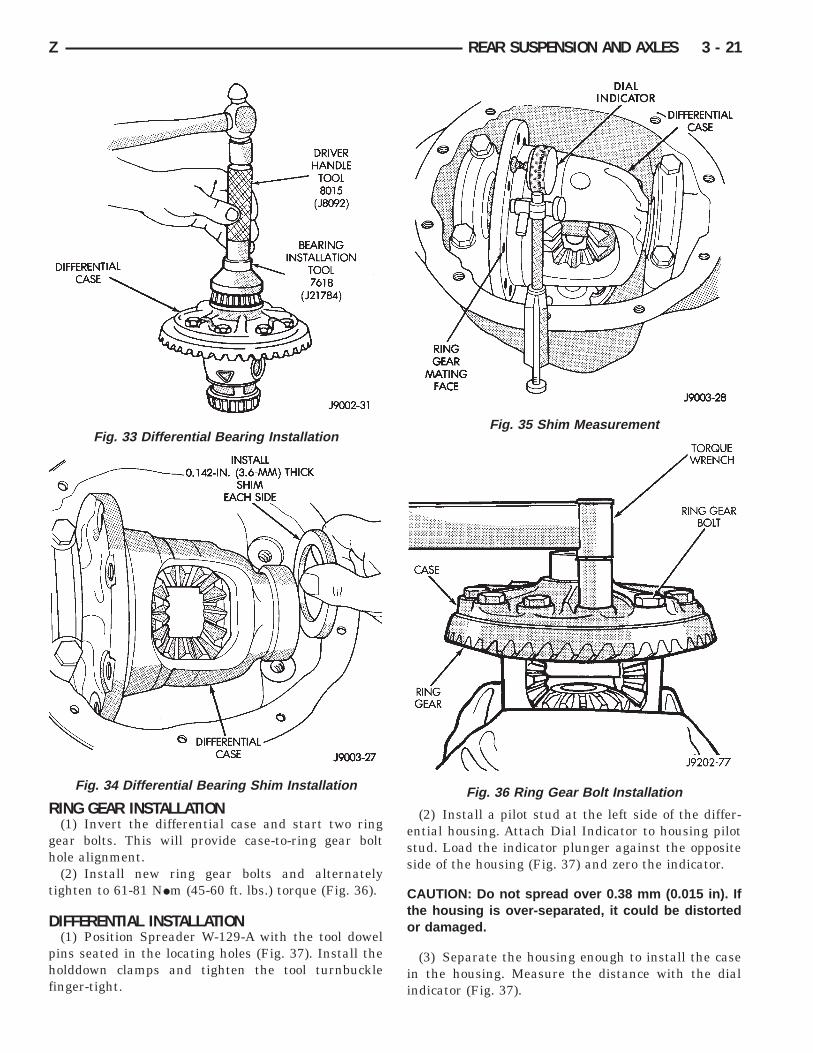
RING GEAR INSTALLATION(1) Invert the differential case and start two ring
gear bolts. This will provide case-to-ring gear bolthole alignment.
(2) Install new ring gear bolts and alternatelytighten to 61-81 NIm (45-60 ft. lbs.) torque (Fig. 36).
DIFFERENTIAL INSTALLATION(1) Position Spreader W-129-A with the tool dowel
pins seated in the locating holes (Fig. 37). Install theholddown clamps and tighten the tool turnbucklefinger-tight.
(2) Install a pilot stud at the left side of the differ-ential housing. Attach Dial Indicator to housing pilotstud. Load the indicator plunger against the oppositeside of the housing (Fig. 37) and zero the indicator.
CAUTION: Do not spread over 0.38 mm (0.015 in). Ifthe housing is over-separated, it could be distortedor damaged.
(3) Separate the housing enough to install the casein the housing. Measure the distance with the dialindicator (Fig. 37).
Fig. 33 Differential Bearing Installation
Fig. 34 Differential Bearing Shim Installation
Fig. 35 Shim Measurement
Fig. 36 Ring Gear Bolt Installation
Z REAR SUSPENSION AND AXLES 3 - 21

(4) Remove the dial indicator.(5) Install differential and outboard shim/spacer
(selected thickness) in housing.(6) Install case in the housing. Tap the differential
case to ensure the bearings are fully seated (Fig. 38).Remove the spreader.
(7) Install the bearing caps at their original loca-tions (Fig. 39). Tighten the bearing cap bolts to 77NIm (57 ft. lbs.) torque.
BACKLASH AND CONTACT PATTERN ANALYSIS(1) Rotate assembly several revolutions to seat
bearings. Measure backlash at three equally spacedlocations around the perimeter of the ring gear with adial indicator (Fig. 40).
The ring gear backlash must be within 0.005 -0.009 inch (0.12 - 0.23 mm). It cannot vary morethan 0.002 inch (0.05 mm) between the pointschecked.
If backlash must be adjusted, spacers are availablein various thicknesses. Adjust the backlash accord-ingly (Fig. 41). DO NOT INCREASE THE TOTALSHIM PACK THICKNESS, EXCESSIVE BEAR-ING PRELOAD AND DAMAGE WILL OCCUR.
The ring gear teeth contact patterns will show if thepinion gear depth shim(s) have the correct thickness.It will also show if the ring gear backlash has beenadjusted correctly. The backlash must be maintainedwithin the specified limits until the correct tooth con-tact patterns are obtained.
(2) Apply a thin coat of hydrated ferric oxide, tothe ring gear teeth.
(3) Rotate the ring gear one complete revolution inboth directions while a load is being applied. Insert apry bar between the differential housing and the case
Fig. 37 Spread Differential Housing
Fig. 38 Differential Installation
Fig. 39 Differential Bearing Cap Reference Letters
Fig. 40 Ring Gear Backlash Measurement
3 - 22 REAR SUSPENSION AND AXLES Z

flange. This action will produce distinct contact pat-terns on both the drive side and coast side of the ringgear teeth.
(4) Note patterns in compound. Refer to (Fig. 42)for interpretation of contact patterns and adjust ac-cordingly.
Fig. 41 Backlash Shim Adjustment
Z REAR SUSPENSION AND AXLES 3 - 23

Fig. 42 Gear Tooth Contact Patterns
3 - 24 REAR SUSPENSION AND AXLES Z

FINAL ASSEMBLY(1) Install the axle shafts. Refer to Axle Shaft In-
stallation within this group.(2) Scrape the residual sealant from the housing
and cover mating surfaces. Clean the mating surfaceswith mineral spirits. Apply a bead of MOPARt Sili-cone Rubber Sealant on the housing cover (Fig. 43).Allow the sealant to cure for a few minutes.
Install the housing cover within 5 minutes af-ter applying the sealant. If not installed thesealant must be removed and another bead ap-plied.
(3) Install the cover on the differential with theattaching bolts. Install the identification tag. Tightenthe cover bolts to 47 NIm (35 ft. lbs.) torque.
CAUTION: Overfilling the differential can result inthe lubricant foaming and overheating.
(4) Refill the differential housing with the specifiedquantity of MOPARt Hypoid Gear Lubricant.
(5) Install the fill hole plug and tighten to 34 NIm(25 ft. lbs.) torque. Fig. 43 Typical Housing Cover With Sealant
Z REAR SUSPENSION AND AXLES 3 - 25

AXLE SPECIFICATIONS
MODEL 35 REAR AXLE
3 - 26 REAR SUSPENSION AND AXLES Z
TRAC-LOK DIFFERENTIAL
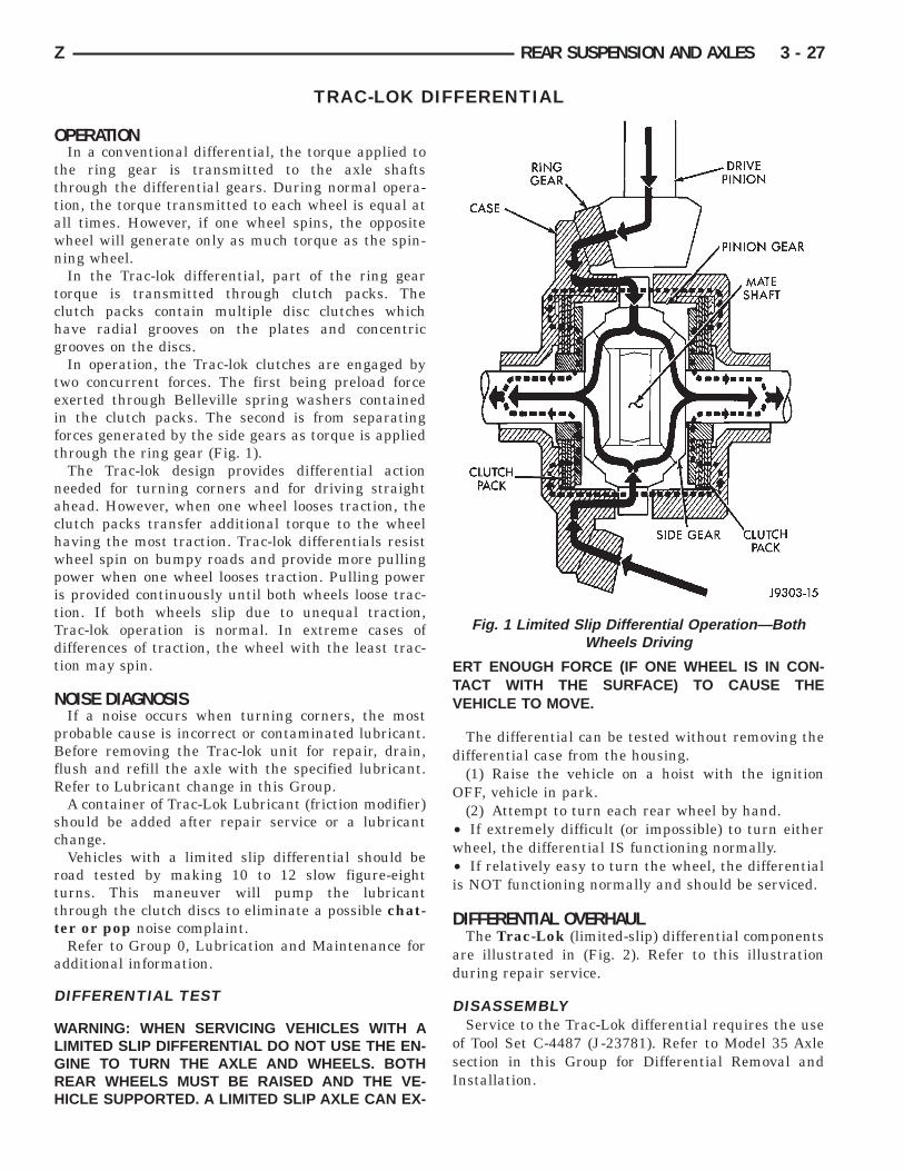
OPERATIONIn a conventional differential, the torque applied to
the ring gear is transmitted to the axle shaftsthrough the differential gears. During normal opera-tion, the torque transmitted to each wheel is equal atall times. However, if one wheel spins, the oppositewheel will generate only as much torque as the spin-ning wheel.
In the Trac-lok differential, part of the ring geartorque is transmitted through clutch packs. Theclutch packs contain multiple disc clutches whichhave radial grooves on the plates and concentricgrooves on the discs.
In operation, the Trac-lok clutches are engaged bytwo concurrent forces. The first being preload forceexerted through Belleville spring washers containedin the clutch packs. The second is from separatingforces generated by the side gears as torque is appliedthrough the ring gear (Fig. 1).
The Trac-lok design provides differential actionneeded for turning corners and for driving straightahead. However, when one wheel looses traction, theclutch packs transfer additional torque to the wheelhaving the most traction. Trac-lok differentials resistwheel spin on bumpy roads and provide more pullingpower when one wheel looses traction. Pulling poweris provided continuously until both wheels loose trac-tion. If both wheels slip due to unequal traction,Trac-lok operation is normal. In extreme cases ofdifferences of traction, the wheel with the least trac-tion may spin.
NOISE DIAGNOSISIf a noise occurs when turning corners, the most
probable cause is incorrect or contaminated lubricant.Before removing the Trac-lok unit for repair, drain,flush and refill the axle with the specified lubricant.Refer to Lubricant change in this Group.
A container of Trac-Lok Lubricant (friction modifier)should be added after repair service or a lubricantchange.
Vehicles with a limited slip differential should beroad tested by making 10 to 12 slow figure-eightturns. This maneuver will pump the lubricantthrough the clutch discs to eliminate a possible chat-ter or pop noise complaint.
Refer to Group 0, Lubrication and Maintenance foradditional information.
DIFFERENTIAL TEST
WARNING: WHEN SERVICING VEHICLES WITH ALIMITED SLIP DIFFERENTIAL DO NOT USE THE EN-GINE TO TURN THE AXLE AND WHEELS. BOTHREAR WHEELS MUST BE RAISED AND THE VE-HICLE SUPPORTED. A LIMITED SLIP AXLE CAN EX-
ERT ENOUGH FORCE (IF ONE WHEEL IS IN CON-TACT WITH THE SURFACE) TO CAUSE THEVEHICLE TO MOVE.
The differential can be tested without removing thedifferential case from the housing.
(1) Raise the vehicle on a hoist with the ignitionOFF, vehicle in park.
(2) Attempt to turn each rear wheel by hand.• If extremely difficult (or impossible) to turn eitherwheel, the differential IS functioning normally.• If relatively easy to turn the wheel, the differentialis NOT functioning normally and should be serviced.
DIFFERENTIAL OVERHAULThe Trac-Lok (limited-slip) differential components
are illustrated in (Fig. 2). Refer to this illustrationduring repair service.
DISASSEMBLYService to the Trac-Lok differential requires the use
of Tool Set C-4487 (J-23781). Refer to Model 35 Axlesection in this Group for Differential Removal andInstallation.
Fig. 1 Limited Slip Differential Operation—BothWheels Driving
Z REAR SUSPENSION AND AXLES 3 - 27

(1) Clamp one axle shaft in a vise equipped withsoft jaws (Fig. 3).
(2) Position the differential case on the axle shaft(Fig. 4). Place shop towels under the differential toavoid damage during removal of the ring gear (Fig. 4).
(3) Remove and discard the ring gear bolts. Tapthe ring gear with a rawhide mallet and remove (Fig.5).
(4) Remove the pinion gear mate shaft lock screw(Fig. 6).
(5) Remove the mate shaft with a drift and ham-mer (Fig. 7).
(6) Install and lubricate Step Plate C-4487-1 (Fig.8).
(7) Assemble Threaded Adapter C-4487-3 into topside gear. Thread forcing Screw C-4487-2 into adapteruntil it becomes centered in adapter plate.
(8) Position a small screw driver in slot ofThreaded Adapter C-4487-3 (Fig. 9) to preventadapter from turning.
Fig. 2 Trac-Lok Differential Components
Fig. 3 Axle Shaft As Holding Fixture
Fig. 4 Differential Case On Shaft
3 - 28 REAR SUSPENSION AND AXLES Z

(9) Tighten forcing screw tool enough to relieveclutch pack tension. Remove both pinion thrustwashers (Fig. 10).
(10) Loosen the forcing screw tool until the clutchpack tension is relieved.
(11) Insert Turning Bar C-4487-4 in case. Rotatecase with tool until pinion gears can be removed(Fig. 11).
(12) Remove top side gear and clutch pack. Keepplates in correct order during removal (Fig. 12).
(13) Remove case from fixture. Remove remainingclutch pack.
(14) Remove clutch pack retaining clips. Markeach clutch pack for installation reference.
Fig. 5 Ring Gear Removal
Fig. 6 Mate Shaft Lock Screw
Fig. 7 Mate Shaft Removal
Fig. 8 Step Plate Tool Installation
Fig. 9 Threaded Adapter Installation
Z REAR SUSPENSION AND AXLES 3 - 29

CLEANING AND INSPECTION(1) Clean all components (Fig. 2) in cleaning sol-
vent. Dry components with compressed air.(2) Inspect clutch pack plates for wear, scoring or
damage. Replace both clutch packs if any one compo-nent in either pack is damaged.
(3) Inspect side and pinion gears. Replace any gearthat is worn, cracked, chipped or damaged.
(4) Inspect differential case and pinion shaft. Re-place if worn or damaged.
ASSEMBLY(1) The clutch discs are replaceable as complete
sets only. If one clutch disc pack is damaged,
both packs must be replaced. Lubricate each com-ponent with gear lubricant before assembly and in-stallation.
(2) Assemble the clutch discs into packs (Fig. 13).(3) Secure disc packs with retaining clips (Fig. 13).(4) Position assembled clutch disc packs on the side
gear hubs.
(5) Position case on axle fixture.
Fig. 10 Remove Pinion Thrust Washer
Fig. 11 Pinion Gear Removal
Fig. 12 Side Gear & Clutch Disc Removal
Fig. 13 Clutch Disc Pack
3 - 30 REAR SUSPENSION AND AXLES Z

(6) Install clutch pack and side gear in lower bore(Fig. 14). Be sure clutch pack retaining clips re-main in position and are seated in the casepockets.
(7) Install lubricated Step Plate C-4487-1 on firstclutch pack (Fig. 15).
(8) Install the upper side gear and clutch disc pack(Fig. 15).
(9) Hold assembly in position. Insert ThreadedAdapter C-4487-3 into top side gear, insert forcingScrew C-4487-4.
(10) Tighten forcing screw tool to compress clutchdiscs.
(11) Install pinion gears. Rotate case with TurningBar C-4487-4. Make sure holes of pinion mate gearsare aligned with case.
(12) Tighten forcing screw to compress theBelleville plates. Lubricate and install pinion gearthrust washers with a small screw driver.
(13) Install the following components in the differ-ential case.• Pinion gears and thrust washers• Pinion gear mate shaft (align holes in shaft andcase)
(14) Install the pinion mate shaft lock screw withLoctitet on the threads. Tighten the screw to 19 NIm(14 ft. lbs.) torque.
If replacement gears and thrust washers wereinstalled, it is not necessary to measure the gearbacklash. Correct fit is due to close machiningtolerances during manufacture.
(15) Invert the differential case and start two ringgear bolts. This will provide case-to-ring gear bolthole alignment.
(16) Install new ring gear bolts and alternatelytighten to 61-81 NIm (45-60 ft. lbs.) torque (Fig. 16).
(17) Lubricate all differential components with hy-poid gear lubricant.
Fig. 14 Clutch Discs & Lower Side Gear Installation
Fig. 15 Upper Side Gear & Clutch Disc PackInstallation
Fig. 16 Ring Gear Bolt Installation
Z REAR SUSPENSION AND AXLES 3 - 31

TORQUE SPECIFICATIONS
REAR SUSPENSION COMPONENTS REAR AXLE MODEL 35
3 - 32 REAR SUSPENSION AND AXLES Z