REAR AXLE - jholst.net Home Pagejholst.net/65-service-manual/rear-axle.pdf · 2018-02-25 · with...
18
REAR AXLE GROUP 3 CONTENTS Page DESCRIPTION 1 SERVICE DIAGNOSIS 1 SERVICE PROCEDURES 1 Description The rear axle assembly is a semi-floating type and may be divided into four subassemblies; axle drive shafts with related parts, differential with drive gear, SURE GRIP DIFFERENTIAL . SPECIFICATIONS AND TIGHTENING REFERENCE Page . 15 (In Back of Manual) drive pinion with carrier, and the axle housing. It is not necessary to remove the entire assembly to service any of the above parts with the exception of the axle housing itself. (Fig. 1). SERVICE DIAGNOSIS Condition Possible Cause Correction REAR AXLES REAR AXLE NOISE (a) Wheel loose on axle drum. (a) Tighten wheel in sequence outline in "Wheels and Tires." (b) Worn drum or worn axle shaft key ways. (b) Replace drum or axle shaft as necessary. (c) Wheel hub bolts loose. (c) Tighten bolts to correct torque. (d) Brinelled or scored wheel bearings. (d) Replace wheel bearings. (e) Insufficient lubrication. (e) Add the specified lubricant as required. (f) Bent axle shaft or wheel and hub. (f) Replace wheel, hub or drum as necessary. (9) Lubricant level low. (g) Add lubricant as required. (h) End play in drive pinion bearing. (h) Measure and adjust end play. (0 Excessive gear lash between drive gear and (i) Measure and adjust gear lash. pinion. (i) Loose drive pinion companion flange nut. (j) Tighten flange nut to 240 (min.) foot-pounds torque. 00 Damaged gears. (k) Replace gears as required. OVER-HEATING OF THE (a) Lubricant level too low. (a) Add the specified lubricant as required. AXLE UNIT (b) Bearing adjusted too tightly. (b) Adjust bearings correctly. (c) Excessive wear in gears. (c) Replace excessively worn gears. LOSS OF LUBRICANT (a) Lubricant level too high. (a) Remove excessive lubricant. (b) Improper type lubricant. (b) Remove lubricant and replace with the speci- fied type. "(c) Clogged breather. (c) Clean breather thoroughly. (d) Oil seals worn. (d) Replace seals as required. SERVICE PROCEDURES REAR AXLE SHAFT Removal (1) Remove the wheel and the brake drum. (2) Through the hole in the axle shaft flange, re- move the five nuts from the axle shaft retainer plate. The right hand shaft with the adjuster in the retainer plate will also have a lock on one of the studs that will be removed at this time. (Figs. 2 and 3). (3) Pull the axle shaft assembly with Tool C-3971, (Fig. 4). (4) The inner seal should be removed at this time using Tool C-637 (Fig. 5). Reinstall the seal using Tool C-839 (Fig. 6). Disassembly (1) Install the axle shaft in a vise and notch the col- lar (Fig. 7). Slide the collar off the shaft.
Transcript of REAR AXLE - jholst.net Home Pagejholst.net/65-service-manual/rear-axle.pdf · 2018-02-25 · with...

REAR AXLE GROUP 3
CONTENTS
Page
DESCRIPTION 1 SERVICE DIAGNOSIS 1 SERVICE PROCEDURES 1
Description The rear axle assembly is a semi-floating type and
may be divided into four subassemblies; axle drive shafts with related parts, differential with drive gear,
SURE GRIP DIFFERENTIAL . SPECIFICATIONS AND
TIGHTENING REFERENCE
Page
. 15
(In Back of Manual)
drive pinion with carrier, and the axle housing. It is not necessary to remove the entire assembly to service any of the above parts with the exception of the axle housing itself. (Fig. 1).
SERVICE DIAGNOSIS Condi t ion P o s s i b l e C a u s e Correct ion
R E A R A X L E S REAR AXLE N O I S E (a) Whee l loose on axle drum. (a) Tighten wheel in sequence outline in "Wheels
a n d Tires." (b) Worn drum or worn axle shaft key ways. (b) Replace drum or axle shaft as necessary.
(c) Whee l hub bolts loose. (c) Tighten bolts to correct torque.
(d) Brinelled or scored wheel bearings. (d) Replace wheel bearings. (e) Insufficient lubrication. (e) A d d the specified lubricant as required.
(f) Bent ax le shaft or wheel and hub. (f) Replace wheel , hub or drum as necessary.
(9) Lubricant level low. (g) A d d lubricant as required. (h) End play in drive pinion bearing. (h) Measure and adjust end play.
(0 Excessive gear lash between drive gear and (i) Measure and adjust gear lash. pinion.
(i) Loose drive pinion companion flange nut. (j) Tighten flange nut to 240 (min.) foot-pounds torque.
00 Damaged gears. (k) Replace gears as required.
O V E R - H E A T I N G O F THE (a) Lubricant level too low. (a) A d d the specified lubricant as required. AXLE UNIT (b) Bearing adjusted too tightly. (b) Adjust bearings correctly.
(c) Excessive wear in gears. (c) Replace excessively worn gears.
L O S S O F LUBRICANT (a) Lubricant level too high. (a) Remove excessive lubricant.
(b) Improper type lubricant. (b) Remove lubricant and replace with the specified type.
"(c) C logged breather. (c) C lean breather thoroughly.
(d) Oi l seals worn. (d) Replace seals as required.
SERVICE PROCEDURES REAR AXLE SHAFT Removal
(1) Remove the wheel and the brake drum. (2) Through the hole in the axle shaft flange, re
move the five nuts from the axle shaft retainer plate. The right hand shaft with the adjuster in the retainer plate wil l also have a lock on one of the studs that wil l be removed at this time. (Figs. 2 and 3).
(3) Pull the axle shaft assembly with Tool C-3971, (Fig. 4).
(4) The inner seal should be removed at this time using Tool C-637 (Fig. 5). Reinstall the seal using Tool C-839 (Fig. 6). Disassembly
(1) Install the axle shaft in a vise and notch the collar (Fig. 7). Slide the collar off the shaft.

3-2 REAR AXLE
=> rat- -NK363
i £ 1 .?i
CAUTION: To prevent the possibility of nicking the shaft during the grinding operation, slide protective sleeve SP5041 over the sealing surfaces of the axle shaft and next to the bearing.
Fig. 2—i##f Shelf (Disassembled)
BLOCKS BEARING REMOVING SP-5020
SCREWS SP-5026
WASHERS SP-320
T~—
SLEEVE SP-5041
ADAPTER SP-5021
ADAPTER S P - 5 0 1 5
\
RING-BLOCK HOLDING SP-5017 NK360
Fig . 3—ftighf Shcrff (Disassembled) F , g . 4 — T o o / Set C -397F
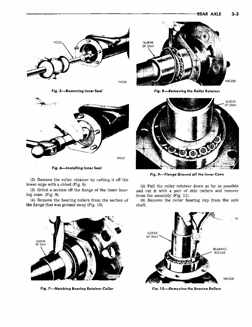
Fig. 5—Removing Inner Seal
Fig. 6 — Ins ta l l ing Inner Seal
(2) Remove the roller retainer by cutting it off the lower edge with a chisel (Fig. 8).
(3) Grind a section off the flange of the inner bearing cone. (Fig. 9).
(4) Remove the bearing rollers from the section of the flange that was ground away (Fig. 10).
Fig. 7—Notching Bearing Retainer Collar
Fig. 8—-Removing Qh® RoShir Uletiaineir
Fig. 9—Flange Ground off the Inner Cone
(5) Pull the roller retainer down as far as possible and cut it with a pair of side cutters and remove from the assembly (Fig. 11).
(6) Remove the roller bearing cup from the axle shaft.
F/a. 70-—Re mo vina the Bearina Rollers

3-4 REAR AXLE'
S L E E V E
S P - 5 0 4 T
Fig. 11—Cutting out the Roller Bearing Retainer
(7) Using Tool C-3971, remove the bearing cone. Tighten the bolts alternately until the cone is removed (Fig. 12).
(8) Replace the seal in the retainer plate. Assembly
(1) Install the retainer plate on the axle shaft. (2) Install a new bearing cone, cup and collar using
Tool C-3971 (Fig. 13). (3) Tighten the long bolts alternately until the bear
ing and collar are installed. Installation of Axle Shaft
(1) Install a new gasket Chrysler Part No. 2467173 on the left end of the housing, add the brake support plate and Chrysler Part No. 2404191 gasket.
(2) Slide the left axle shaft assembly into position carefully to avoid damaging the new inner seal. Install (5) retainer plate nuts 30 to 35 foot-pounds torque.
(3) Repeat step (1) for right side of housing. (4) Back off the adjuster on the right axle shaft as
sembly until the inner face of the adjuster is flush with the inner face of the retainer. Slide the right axle shaft assembly into the housing carefully to avoid
- 4 • : • " . NK362
Fig. 13—-Installing New Bearing and Collar
damaging the new inner seal. Install (5) retainer plate nuts 30-35 foot-pounds torque.
(5) Using a dial indicator mounted on the brake support (Fig. 14) tighten the adjuster until both wheel bearings are seated and there is zero end play in the axle shafts. Back off the adjuster approximately four notches to establish a shaft end play of .013" to .023".
(6) Hit the end of the left shaft with a non-metallic mallet to move the right wheel bearing cup against the adjuster, and rotate the shaft so that a true end play reading is indicated.
(7) Remove one retainer plate nut. Install the adjuster lock. If the tab on the lock does not mate with a notch on the adjuster, turn adjuster until it does. Install the nut 30 to 35 foot-pounds torque.
(8) Re-test the shaft end play. If it is not between .013'" to .023", then repeat the adjustment procedure.
(9) Remove the dial indicator and install the brake drum, drum retaining clips and the wheel.
IP i
• r e
NK361.
Fig 72- -Removing the Bearing Cone with ToolC-3971
N K 1 2 8
Fig. 14—Measuring Driving Axle Shaft End Play
REAR AXLE 3-5
REAR AXLE HOUSING
Removal (1) Support the rear end of the vehicle on the frame
pads. (2) Remove the rear axle lubricant with a suction
gun. (3) Disconnect the propeller shaft at the rear axle
end. (4) Disconnect the hydraulic brake hose at the con
nection on the left side of the underbody. (5) Disconnect the shock absorbers. (6) Disconnect the parking brake cables. (7) Remove the nuts from the " U " spring bolts. (8) Remove the assembly from the vehicle.
Installation (1) Position the housing under the vehicle. Be sure
the spring seat center holes engages the spring center bolt.
(2) Install the " U " bolts and nuts, and tighten to 50 foot-pounds torque.
(3) Connect the parking brake cables and adjust. (4) Connect the shock absorbers. (5) Connect the hydraulic brake hose and bleed the
brakes. (6) Fil l the axle with the proper amount of lubri
cant. (7) Connect the propeller shaft. (8) Lower the vehicle and test the operation.
DIFFERENTIAL AND CARRIER
Carrier Removal (1) Remove the axle drive shafts. (2) Disconnect the rear universal joint and sup
port the propeller shaft up and out of the way. (3) Remove the lubricant from the axle housing us
ing a suction gun.
Fig. 7 5 — C h e c k i n g for Runout and Zero End Play
Fig. 16—Removing Companion Flange
(4) Remove the attaching nuts and lift the rear axle carrier assembly from the axle housing.
DISASSEMBLY Carrier Disassembly
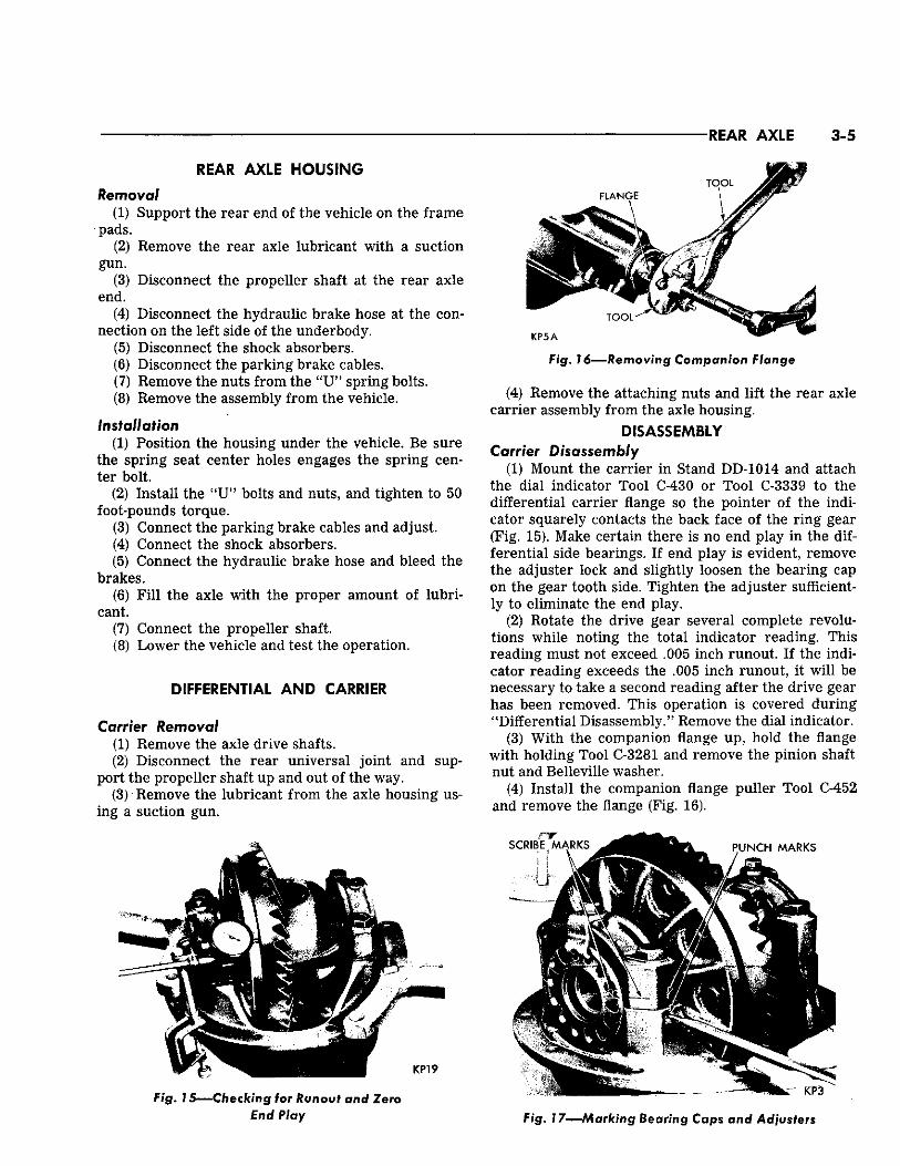
(1) Mount the carrier in Stand DD-1014 and attach the dial indicator Tool C-430 or Tool C-3339 to the differential carrier flange so the pointer of the indicator squarely contacts the back face of the ring gear (Fig. 15). Make certain there is no end play in the differential side bearings. If end play is evident, remove the adjuster lock and slightly loosen the bearing cap on the gear tooth side. Tighten the adjuster sufficiently to eliminate the end play.
(2) Rotate the drive gear several complete revolutions while noting the total indicator reading. This reading must not exceed .005 inch runout. If the indicator reading exceeds the .005 inch runout, it wil l be necessary to take a second reading after the drive gear has been removed. This operation is covered during "Differential Disassembly." Remove the dial indicator.
(3) With the companion flange up, hold the flange with holding Tool C-3281 and remove the pinion shaft nut and Belleville washer.
(4) Install the companion flange puller Tool C-452 and remove the flange (Fig. 16).
Fig. 17—Marking Bearing Caps and Adjusters
3-6 REAR AXLE
(5) Install the oil seal puller Tool C-748 by screwing it securely into the pinion oil seal and tighten the puller screw to remove the seal.
(6) While holding one hand over the companion flange end of the carrier, invert the carrier in the stand. The front bearing cone shim pack and bearing spacer (where used) will drop from the carrier.
(7) Apply identifying punch marks on the bearing supports of the differential carrier, differential bearing caps, and bearing adjusters for reassembly purposes (Fig. 17).
(8) Remove each of the differential bearing adjuster lock screws and locks.
(9) With a % inch socket wrench, loosen the bearing cap bolts (one on each side) and back off the bearing adjusters slightly with spanner wrench Tool C-406A, to remove the differential case bearing preload. Remove the bearing cap bolts, caps and bearing adjusters.
(10) Remove the differential assembly with the bearing cups. Make certain that each bearing cup remains with its respective bearing.
(11) Withdraw the pinion and rear bearing from the carrier.
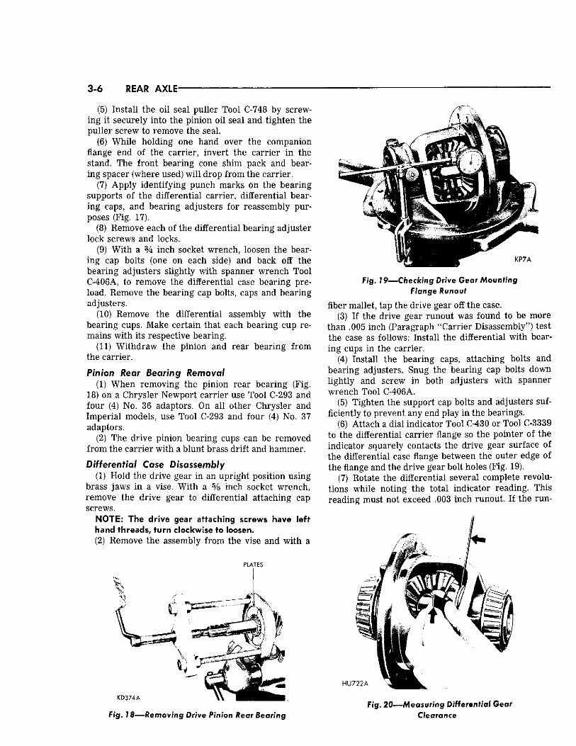
Pinion Rear Bearing Removal (1) When removing the pinion rear bearing (Fig.
18) on a Chrysler Newport carrier use Tool C-293 and four (4) No. 36 adaptors. On all other Chrysler and Imperial models, use Tool C-293 and four (4) No. 37 adaptors.
(2) The drive pinion bearing cups can be removed from the carrier with a blunt brass drift and hammer.
Differential Case Disassembly (1) Hold the drive gear in an upright position using
brass jaws in a vise. With a % inch socket wrench, remove the drive gear to differential attaching cap screws.
NOTE: The drive gear attaching screws have left hand threads, turn clockwise to loosen. (2) Remove the assembly from the vise and with a
PLATES
Fig. 18—Removing Drive Pinion Rear Bearing
Fig. 19—Checking Drive Gear Mounting Flange Runout
fiber mallet, tap the drive gear off the case. (3) If the drive gear runout was found to be more
than .005 inch (Paragraph "Carrier Disassembly") test the case as follows: Install the differential with bearing cups in the carrier.
(4) Install the bearing caps, attaching bolts and bearing adjusters. Snug the bearing cap bolts down lightly and screw in both adjusters with spanner wrench Tool C-406A.
(5) Tighten the support cap bolts and adjusters sufficiently to prevent any end play in the bearings.
(6) Attach a dial indicator Tool C-430 or Tool C-3339 to the differential carrier flange so the pointer of the indicator squarely contacts the drive gear surface of the differential case flange between the outer edge of the flange and the drive gear bolt holes (Fig. 19).
(7) Rotate the differential several complete revolutions while noting the total indicator reading. This reading must not exceed .003 inch runout. If the run-
Fig. 20—Measuring Differential Gear Clearance

I E A I AXLE 3 -7
Fig. 21—Removing Differential Bearings
out is in excess of .003 inch, the differential case must be replaced.
(8) Measure the side gear clearances between the gear and case (Fig. 20). Clearances should be from .001 to .012 inch. I f the clearance exceeds .012 inch, install new thrust washers.
(9) From the back side of the drive gear flange, drive the differential pinion shaft lock pin out of the
case with a flat nose drift and hammer. The lock pin is a ¥4 inch hollow split type pin. (The hole is reamed only part way through, making it necessary to remove the lock pin from one direction.)
(10) Drive the pinion shaft out with a brass drift and hammer and remove the axle drive shaft thrust block.
(11) Rotate one differential side gear until each pinion appears at the large opening of the case. Remove each pinion and thrust washer at that time.
(12) Remove the two differential side gears and thrust washers.
CLEANING AND INSPECTION (1) Clean all parts in fast evaporating mineral spir
its or a dry cleaning solvent and with the exception of the bearings, dry with compressed air.
(2) Inspect the differential bearing cones and cups for pitting, spalling or other visible damage. If replacement is necessary, remove the bearings from the differential case with puller Tool C-293 and four adaptor plates No. 18 (Fig. 21).
(3) Inspect the differential case for elongated or enlarged pinion shaft holes, the side gear counterbores and the four thrust washer contacting surfaces for galling, metal deposits or raised portions of metal. If any of the above conditions exist, satisfactory correction must be made or the case replaced. Inspect the case for cracks or other visible damage which might render it unfit for further service. (Figs. 22 and 23).
(4) Inspect the differential pinion shaft for excessive wear. Replace as necessary.
(5) Inspect the differential pinion gears for excessive wear, cracks, chipped teeth or other visible dam-
SHAFT
THRUST WASHER
BEARING I CONE \
CUP\ \ BOLT
DIFFERENTIAL CASE
PIN
BEARING CONE
BOLT AND LOCKWASHER
LOCK
ADJUSTER
CUP
DRIVE GEAR AND PINION
CAP
\
BEARING CONE
SHIMS
CARRIER
FLANGE
SEAL NUT
# ; c > r K 5 # ^ J / \ b o l t
SIDE GEAR THRUST WASHER \ xTHRUST BLOCK
PINION THRUST WASHER SIDE GEAR
THRUST WASHER
BEARING CONE
ADJUSTING WASHER
CUP PLUG
CAP
ADJUSTER
LOCK
BOLT AND LOCKWASHER
WASHER
GUARD
K P 1 B
Fig. 22—Differential Carrier Assembly (Disassembled) (AC-1) (Small Pinion)
3-8 HEAR AXLE
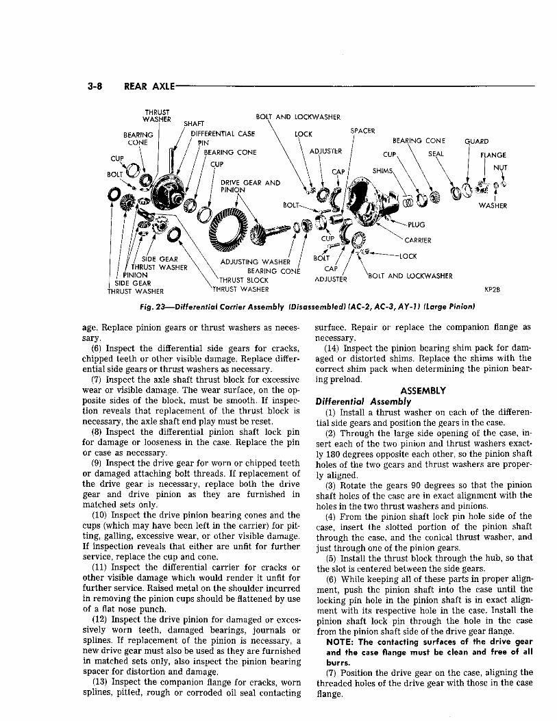
Fig. 23—Differential Carrier Assembly (Disassembled) (AC-2, AC-3, AY-1) (Large Pinion)
age. Replace pinion gears or thrust washers as necessary.
(6) Inspect the differential side gears for cracks, chipped teeth or other visible damage. Replace differential side gears or thrust washers as necessary.
(7) Inspect the axle shaft thrust block for excessive wear or visible damage. The wear surface, on the opposite sides of the block, must be smooth. If inspection reveals that replacement of the thrust block is necessary, the axle shaft end play must be reset.
(8) Inspect the differential pinion shaft lock pin for damage or looseness in the case. Replace the pin or case as necessary.
(9) Inspect the drive gear for worn or chipped teeth or damaged attaching bolt threads. If replacement of the drive gear is necessary, replace both the drive gear and drive pinion as they are furnished in matched sets only.
(10) Inspect the drive pinion bearing cones and the cups (which may have been left in the carrier) for pitting, galling, excessive wear, or other visible damage. If inspection reveals that either are unfit for further service, replace the cup and cone.
(11) Inspect the differential carrier for cracks or other visible damage which would render it unfit for further service. Raised metal on the shoulder incurred in removing the pinion cups should be flattened by use of a flat nose punch.
(12) Inspect the drive pinion for damaged or excessively worn teeth, damaged bearings, journals or splines. If replacement of the pinion is necessary, a new drive gear must also be used as they are furnished in matched sets only, also inspect the pinion bearing spacer for distortion and damage.
(13) Inspect the companion flange for cracks, worn splines, pitted, rough or corroded oil seal contacting
surface. Repair or replace the companion flange as necessary.
(14) Inspect the pinion bearing shim pack for damaged or distorted shims. Replace the shims with the correct shim pack when determining the pinion bearing preload.
ASSEMBLY Differential Assembly
(1) Install a thrust washer on each of the differential side gears and position the gears in the case.
(2) Through the large side opening of the case, insert each of the two pinion and thrust washers exactly 180 degrees opposite each other, so the pinion shaft holes of the two gears and thrust washers are properly aligned.
(3) Rotate the gears 90 degrees so that the pinion shaft holes of the case are in exact alignment with the holes in the two thrust washers and pinions.
(4) From the pinion shaft lock pin hole side of the case, insert the slotted portion of the pinion shaft through the case, and the conical thrust washer, and just through one of the pinion gears.
(5) Install the thrust block through the hub, so that the slot is centered between the side gears.
(6) While keeping all of these parts in proper alignment, push the pinion shaft into the case until the locking pin hole in the pinion shaft is in exact alignment with its respective hole in the case. Install the pinion shaft lock pin through the hole in the case from the pinion shaft side of the drive gear flange.
NOTE: The contacting surfaces of the drive gear and the case flange must be clean and free of all burrs. (7) Position the drive gear on the case, aligning the
threaded holes of the drive gear with those in the case flange.

REAR AXLE 3-9
(8) Insert the drive gear cap screws (left hand threads) through the case flange and into the drive gear. After all cap screws are properly started, tap the drive gear onto the flange.
(9) Position the unit between the brass jaws of the vise and alternately torque tighten each cap screw to 60 foot-pounds torque.
(10) Position each differential bearing cone on the hub of the case (taper away from the drive gear) and with installing Tool DD-1005, Install the bearing cones. An arbor press may be used in conjunction with the installing tool.
CAUTION: Never exert pressure against the bearing cage, since this would damage the bearing.
Pinion Bearing Cup Installation (1) Place the bearing cups squarely in position. As
semble Tool C-758 (Fig. 24) by placing spacer SP-2919 (on Chrysler Newport AC-1) followed by the rear pinion bearing cone over the main screw of the tool and inserting i t into the carrier from the gear side.
(2) Place the front pinion bearing over the main screw followed by compression sleeve SP-535, centralizing washer SP-534, and main screw nut SP-533. Hold the compression sleeve with the companion flange holding Tool C-3281 and tighten the nut (Fig. 25) allowing the tool to rotate as the nut is being tightened in order not to damage the bearing or cups.
NOTE: Do not remove the tool after installing the cups.
Pinion Bearing Preload-Depth of Mesh Installation Model A C - 1 , Using Tool C-758
Two types of drive pinions are used. The method of determining pinion depth of mesh and bearing preload are the same for both pinions, however, the sequence of making the two adjustments changes.
GAUGE BLOCK SP-528 W R E N C H
_ r >SCREW
CROSSBORE TUBE SP-561
V ,* \ l | k SLEEVE SP-2<
lk COMPRESS
-2920
COMPRESSION j l g V SLEEVE SP-535
^ M A I N BODY X SP-526 - - - /
! — ;
^Sl COMPRESSION \ X NUT SP-533
% J
SPACER SPACER PINION LOCATING SPACER SP-2919 SP-1730 SP-539 NK68
Fig. 24—Rear Axle Setting Gauge Set f o o l C-758-D4
SPACER WASHER 1 ~ SP-1371
^ = A
SPACER SP-2921
CENTRALIZING WASHER SP-534
KP13A
Fig. 25—Seating the Bearing Cups in Carrier Housing
Pinions used on Models AC-2, AC-3 and Models AY-1, require the depth of mesh adjustment first, while pinions used on Model AC-1 requires the bearing preload adjustment first.
(1) With the tool installed in the carrier, remove the main screw nut, centralizing washer, compression sleeve and the front pinion bearing.
(2) Install the pinion bearing spacer, the larger bore of spacer next to the rear bearing.
(3) Position the sleeve (SP-1730) in the front bearing, making sure the sleeve is flush with the rear of the bearing.
(4) Position the original shims, previously removed from the drive pinion shaft, over the sleeve and slide the sleeve, bearing and shims over the tool main screw until the shims rest against the spacer (Fig. 26).
(5) Install the tool compression sleeve (SP-535) (square end out), centralizing washer (SP-534) and main screw nut (SP-533). Turn the carrier in the stand to bring the nut on top.
(6) Tighten the tool nut to 240 foot-pounds torque, using holding Tool C-3281 on the compression sleeve to hold the assembly in several positions to make a complete revolution while tightening. Remove the holding tool and rotate the assembly several turns in both directions to align the bearing rollers. Retest the torque to 240 foot-pounds (torque may have dimin-
PINION LOCATING WASHER OR SHIM
ASSEMBLY O F SP-526 CARRIER
/ ASSEMBLY SP-528 X. \ / SP-2919 J V
^ -in 4
-.1
SP-1730 KP152
Fig. 26—Pinion Preload with S p a c e r (8 % " Ring Gear)

3-10 REAR AXLE
ished as the bearing rollers were aligned by rotating). (7) Using an inch pound torque wrench Tool C-685,
and with the handle of the wrench floating, read the torque when the wrench is moving through at least one full rotation. The correct reading is 20 to 30 inch-pounds for a new bearing, and zero to 15 inch-pounds for bearing in use and should be uniform during the full rotations. If the bearing preload is more than 30 inch-pounds, a thicker shim should be used under the front bearing. If the bearing preload is less than 20 inch-pounds, a thinner shim should be used. Shims are available in thicknesses of .010, .012, .014, .016 and .018 inch. After proper pinion bearing preload is established, do not remove the tool.
Depth of Mesh The position of the drive pinion with respect to the
drive gear (depth of mesh) is determined by the location of the bearing cup shoulders in the carrier and by the portion of the pinion in back of the rear bearing. The thickness of a pinion spacer washer suitable for the carrier can be determined by using Tool C-758.
(1) Invert the carrier in the stand and install gauge block SP-528 or SP-3250 on the end of the tool (Fig. 27) , attaching it to the tool with the Allen screw. The flat portion of the spacer should be facing the differential bearing pedestals and the offset of the spacer (or the large portion) toward the center of the carrier. Tighten the screw with an Allen wrench.
(2) Position arbor SP-561 (part of Tool C-758) in the differential bearing pedestals of the carrier (Fig. 28) . Center the arbor so that an approximate equal distance is maintained at both ends. Position the differential bearing caps and attaching bolts on the carrier pedestals. Insert a piece of .002 inch feeler stock between the arbor and each cap, and tighten the cap bolts securely.
(3) Select the washer that will fit between the tool gauge block and arbor (Fig. 29). The fit must be snug
•pi
Fig. 27—Installing Gauge Block on Tool
Fig. 28—Installing Arbor in Carrier
but not too tight (similar to the pull of a feeler gauge). This washer is used only for determining the correct thickness washer to be used for installation.
(4) To select the proper washer for installation, read the marking on the end of the pinion (—0, — 1 , —2, - f 1, +2 , etc.) When the marking is — (minus, add that amount to the thickness of the washer selected in step 3. When the marking is + (plus), subtract that amount. Example: With a washer .086 inch thick and a pinion marked —2, install spacer washer .088 inch thick (.086 + .002 = .088). Example: With a washer .086 inch thick and a pinion marked +2 , install a spacer washer .084 inch thick. (.086 — .002 — .084) or when a washer .086 inch thick is too loose and the .088 inch is too tight, use a .086 inch spacer washer.
(5) Remove the tool arbor from the carrier. (6) Remove the tool and bearings out of the carrier. (7) Remove the shims, spacer, tool sleeve, and
rear bearing cone from the tool main screw.
Bearing Installation (1) With the shaft end of pinion facing up, install
the correct pinion spacer washer on the pinion gear shaft. These washers have a chamfer on one side.
Fig. 29—Determining Spacer Thickness

REAR AXLE 3-11
Fig. 30—Pin ion Oil Seal Installed
NOTE: The chamfer must face the pinion head. (2) Position the rear bearing cone on the pinion
shaft (small end away from the pinion gear). Make certain that the contacting surfaces of the correct washer, pinion gear, and rear bearing cone are perfectly clean and free of any foreign particles.
(3) Install the rear bearing cone onto the pinion shaft with Tool DD-996. An arbor press may be used in conjunction with the tool.
(4) Install the bearing tubular spacer on the pinion shaft (large bore facing the rear bearing).
(5) Install the selected shim pack. (6) Lubricate the front and rear pinion shaft bear
ing cones with Multipurpose Gear Lubricant. (7) Install the front bearing in its cup in the carrier. (8) Install the oil seal in the carrier with driver Tool
C-3656, lip of seal must face the front bearing. The seal must be driven into the carrier until the tool bottoms against the front pinion bearing cone (Fig. 30).
(9) Insert the pinion shaft up through the carrier.
While supporting the pinion in the carrier, install the companion flange with installing Tool C-496 or DD-999.
(10) Remove the tool and install the plain washer (convex side of washer up) and nut.
(11) Hold the companion flange with holding Tool C-3281. Torque the companion flange nut to 240 footpounds. Rotate the assembly several turns in both directions to align the bearing rollers. Retest the torque to 240 foot-pounds (torque may have diminished as bearing rollers were aligned by rotating).
PINION BEARING PRELOAD AND PINION SETTING
MODELS A C - 2 , A C - 3 , AY-1 USING TOOL C-758-D4
Inspect the bearing cups and carrier for grit and dirt. Assemble spacer SP-2921 to the main section of the tool followed by spacer SP-1730. Install the pinion rear bearing over spacer SP-1730 and against spacer SP-2921 (Fig. 31). Insert the assembly into the carrier housing and install the front bearing over the tool shaft and in its proper position in the bearing cup. Install the tool spacer; tool thrust washer and the tool nut on the shaft. Tighten the tool setting nut to not more than 25 to 50 foot-pounds torque.
Turn the tool several revolutions to permit the bearing rollers to seat. After the bearing rollers have been properly seated, check the bearing preload by rotating the tool with an inch-pound torque wrench. With the bearings lubricated with hypoid gear oil the correct preload should be from 25 to 50 inch-pounds torque.
Assemble gauge block SP-528 or SP-3250 to the main screw attaching it with the alien screw securely. Position tool arbor SP-561 in the differential carrier bearing supports. Insert a piece of .002 inch feeler stock between the arbor and each cap. Install the caps and tighten the bolts to 10 foot-pounds torque.
Fig. 31—Tool C-758 Installed in Housing Models AC-2, AC-3, AY-7

3-12 REAR AXLE
Select a gauge washer that will just pass between the gauge block end of the tool and the machined surface of the bearing arbor. As an example, if a .090 inch spacer can be inserted but a .092 inch spacer cannot be forced between the two surfaces by hand, the .090 inch spacer should be used even though it might feel loose.
Note the end of the drive pinion as it will indicate the amount that should be added or subtracted from the spacer that was selected. As an example, if the pinion shaft indicated plus two a .002 inch thinner spacer should be used for final assembly. As an example, if a spacer selected by the use of the tool is .090 inch it is necessary to deduct .002 inch, therfore, the correct spacer for final assembly would be .088 inch.
To correctly read the markings on the end of the drive pinion, always remember that the plus (+) symbol indicates a deduction of the required spacer thickness, whereas the minus (—) symbol indicates the necessity for a thicker spacer.
When the correct spacer is selected for the drive pinion, disassemble the setting tool from the differential carrier housing and add the pinion positioning spacer just selected to the tool, between spacer SP-2921 and the pinion rear bearing. Install spacer SP-1730 and the pinion bearing adjusting spacer from the previous bearings. Insert the tool assembly in the carrier housing. Place the forward roller bearing over the shaft and in position in the carrier bearing cup. Install the tool spacer, tool nut washer and tool nut on the shaft. Hold the compression sleeve nut with holding Tool C-3281 and tighten the nut to 240 foot-pounds torque. Turn the tool several revolutions to permit the bearing rollers to seat. After the bearing rollers have been properly seated measure the bearing preload by rotating the tool with an inch-pound torque wrench. With the bearing lubricated with Multipurpose Gear Lubricant, the correct preload specifications are from 45 to 50 inch-pounds torque.
If the bearing adjustment does not conform to specifications it will be necessary to change the adjustment by either a thicker or thinner pinion bearing spacer. If the preload is too great it will be necessary to install a thicker spacer and if the pre-load is not sufficient a thinner spacer will be necessary.
When the correct spacer is selected for the drive pinion bearing, disassemble the tool from the differential carrier housing and install the bearings, pinion positioning spacer and bearing spacer to the pinion and install the assembly in the housing. Measure the turning torque,, it should be 20 to 30 inch pounds before installing the seal. If not within specifications, correct as necessary.
Assembly of Pinion Carrier 9
With the shaft end of pinion facing up, install the
selected washer on the pinion stem, with the chamfered side of the washer facing the drive pinion gear. Position the rear bearing on the pinion shaft. Make sure the contacting surfaces of the washer, pinion gear and rear bearing are perfectly clean and free from dirt or foreign particles. Install the rear bearing cone onto the pinion shaft with Tool DD-955. Install the selected shim pack. Lubricate the front and rear bearing. Insert the pinion and bearing assembly in the carrier. Apply a light coat of sealer in the carrier bore at the seal area. Install a new seal with Tool C-3656 until the driver bottoms on the pinion front bearing. Install and support the pinion gear assembly in the carrier, and install the universal joint flange with installing Tool C-496 or DD-999. Install the plain washer (concave side of washer down) and nut. Tighten the flange nut to 240 foot-pounds torque and remove the flange holding tool.
PINION BEARING PRELOAD AND PINION SETTING
(Without Using Special Tool C-758) If the differential assembly was satisfactorily quiet before being disassembled, the drive pinion may be assembled with the original adjusting washers and shims. If replacement parts are installed, or differential adjustment is necessary, the proper thickness washer must be installed between the pinion and rear bearing. The drive gear and pinion are manufactured and lapped in matching sets. The adjustment position in which the best tooth contact is obtained is etched on the end of the pinion shaft. To obtain the proper pinion setting in relation to
the drive gear, the correct thickness thrust washer must be selected before the drive pinion is installed in the carrier. The pinion bearing adjusting washers are available from .084 inch to .100 inch in .002 inch steps. To select the proper thickness thrust washer, proceed as follows: It will be noted that the face of the drive pinion is etched with a plus (+) or minus (—) sign, followed by a number ranging from 1 to 4, or zero (0) marking.
Depth of Mesh If the old and new pinion have the same marking
and if the original bearing is being reused, use a thrust washer of the same thickness. But if the old pinion is marked zero (0) and the new pinion is marked + 2, try a .002 inch thinner washer. If the new pinion is marked —2, try a .002 inch thicker washer.
Pinion Bearing Preload If the bearing cups are to be replaced, place the
bearing cups in position in the carrier and drive the C U D S in place with a suitable drift. After properly positioning of the bearing cups in the carrier, assemble the drive pinion thrust washer (chamfered side down

toward gear) on the drive pinion stem. Install the rear bearing, spacer (if so equipped) and shims on the pinion stem. Insert the pinion shaft into the carrier. Install the front pinion bearing, universal joint flange, washer and nut. Do not install the oil seal. Tighten the drive pinion flange nut to 240 foot-pounds torque. Rotate the drive pinion shaft after tightening the flange nut, to properly seat the bearing rollers in the bearing cups. The pre-load torque required to rotate the pinion shaft with the bearings oiled should be 20 to 30 inch-pounds torque for new bearings and 0 to 15 inch-pounds for bearings in use. Add shims to decrease torque or remove shims to increase torque. After the correct pinion setting and bearing preload has been obtained, remove the drive pinion flange. Install the oil seal. Install the pinion flange, washer and nut. Tighten the pinion nut to the proper torque.
Installation in Carrier (1) Install the differential bearing cup on its respec
tive bearing, and position the assembly in the carrier. (2) Install the differential bearing caps, making cer
tain that the identification marks on the cap correspond with those on the carrier. Install the attaching bolts and tighten the bolts of each cap by hand.
(3) Note the identification marks on the differential bearing adjusters and reinstall each in its respective side.
(4) Screw the adjuster in by hand. No attempt should be made at this time to apply any excessive pressure. To square the bearing cups with the bearing, turn the adjusters " in" with spanner wrenches Tool C-406A (Fig. 32), until cups are properly squared with the bearings and end play is eliminated with some backlash existing between the drive gear and pinion.
KP20
Fig. 32—Adjus t ing Differential Bearings
i
KP21
Fig. 3 3 — M e a s u r i n g Backlash Between Drive Gear and Pinion
(5) While facing each bearing support cap, tighten one bolt 85 to 90 foot-pounds torque on each side.
DRIVE GEAR AND PINION BACK LASH The drive and pinion backlash should be .006 to
.008 inch at the point of minimum backlash. (1) Attach a dial indicator Tool C-340 or C-3339 to
the carrier flange so pointer or indicator is squarely contacting one of the drive gear teeth (drive side) (Fig. 33).
(2) Measure the backlash between the drive gear and pinion. After the first reading is taken, move the dial indicator away from the tooth sufficiently to rotate the drive gear approximately 90 degrees and again measure the backlash. The backlash should be measured in four different positions to determine the least clearance between the drive gear and pinion. After the point of least clearance has been established, mark the drive gear.
NOTE: Do not rotate the drive gear from the point of least clearance until all adjustments have been completed. (3) Turn both bearing adjusters equally (in the same
direction) until the backlash between the drive gear and the pinion is .0005 to .0015 inch. This backlash variation is given to permit alignment and installation of the bearing adjuster lock, lockwasher and attaching bolt. The adjuster must only be turned in a clockwise direction and under no circumstances should be backed off.
(4) Install the adjuster lock on the bearing cap on the back-face side of the drive gear. Side Bearing Preload
(1) Turn the bearing adjuster (tooth side of drive gear) (Fig. 33) in a notch at a time (notch referred to is the adjuster lock holes) until the backlash between the drive gear and pinion is a minimum of .006 inch to .008 inch. This will preload the bearings and es-
tablish the correct backlash. (2) Tighten the remaining two bearing support cap
bolts 85 to 90 foot-pounds torque. (3) Install the remaining adjuster lock, lockwasher
and attaching bolts. Tighten the lock retaining cap screws 15 to 20 foot-pounds torque.
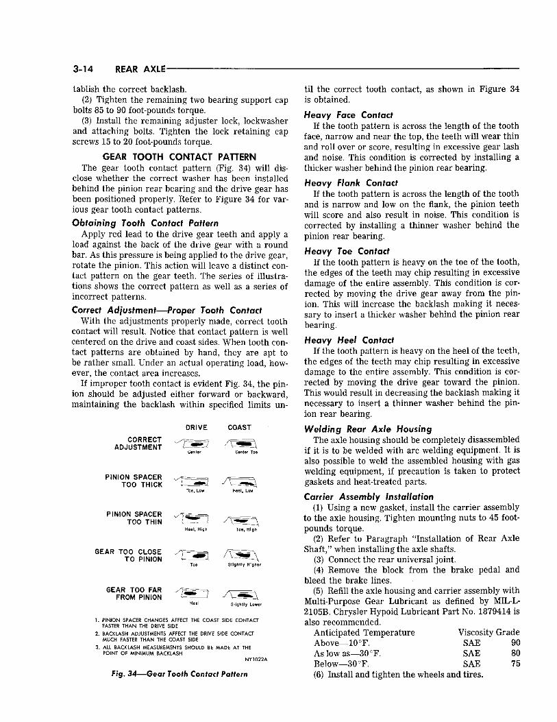
GEAR TOOTH CONTACT PATTERN The gear tooth contact pattern (Fig. 34) will dis
close whether the correct washer has been installed behind the pinion rear bearing and the drive gear has been positioned properly. Refer to Figure 34 for various gear tooth contact patterns. Obtaining Tooth Contact Pattern
Apply red lead to the drive gear teeth and apply a load against the back of the drive gear with a round bar. As this pressure is being applied to the drive gear, rotate the pinion. This action will leave a distinct contact pattern on the gear teeth. The series of illustrations shows the correct pattern as well as a series of incorrect patterns. Correct Adjustment—Proper Tooth Contact
With the adjustments properly made, correct tooth contact will result. Notice that contact pattern is well centered on the drive and coast sides. When tooth contact patterns are obtained by hand, they are apt to be rather small. Under an actual operating load, however, the contact area increases.
If improper tooth contact is evident Fig. 34, the pinion should be adjusted either forward or backward, maintaining the backlash within specified limits un-
DRIVE COAST
CORRECT ADJUSTMENT
PINION SPACER TOO THICK
PINION SPACER TOO THIN
GEAR TOO C L O S E TO PINION
GEAR TOO FAR FROM PINION
Toe, Low
Heel , High
Heel , Low
Toe, High
Sl ight ly Higher
Sl ight ly Lower
1. PINION SPACER CHANGES AFFECT THE COAST SIDE CONTACT FASTER THAN THE DRIVE SIDE
2. BACKLASH ADJUSTMENTS AFFECT THE DRIVE SIDE CONTACT MUCH FASTER THAN THE COAST SIDE
3. ALL BACKLASH MEASUREMENTS SHOULD BE MADE AT THE POINT OF MINIMUM BACKLASH
NY1022A
Fig. 34—Gear Tooth Contact Pattern
t i l the correct tooth contact, as shown in Figure 34 is obtained.
Heavy Face Contact If the tooth pattern is across the length of the tooth
face, narrow and near the top, the teeth will wear thin and roll over or score, resulting in excessive gear lash and noise. This condition is corrected by installing a thicker washer behind the pinion rear bearing.
Heavy Flank Contact If the tooth pattern is across the length of the tooth
and is narrow and low on the flank, the pinion teeth will score and also result in noise. This condition is corrected by installing a thinner washer behind the pinion rear bearing.
Heavy Toe Contact If the tooth pattern is heavy on the toe of the tooth,
the edges of the teeth may chip resulting in excessive damage of the entire assembly. This condition is corrected by moving the drive gear away from the pinion. This will increase the backlash making it necessary to insert a thicker washer behind the pinion rear bearing.
Heavy Heel Contact If the tooth pattern is heavy on the heel of the teeth,
the edges of the teeth may chip resulting in excessive damage to the entire assembly. This condition is corrected by moving the drive gear toward the pinion. This would result in decreasing the backlash making it necessary to insert a thinner washer behind the pinion rear bearing.
Welding Rear Axle Housing The axle housing should be completely disassembled
if it is to be welded with arc welding equipment. It is also possible to weld the assembled housing with gas welding equipment, if precaution is taken to protect gaskets and heat-treated parts.
Carrier Assembly Installation (1) Using a new gasket, install the carrier assembly
to the axle housing. Tighten mounting nuts to 45 footpounds torque.
(2) Refer to Paragraph "Installation of Rear Axle Shaft," when installing the axle shafts.
(3) Connect the rear universal joint. (4) Remove the block from the brake pedal and
bleed the brake lines. (5) Refill the axle housing and carrier assembly with
Multi-Purpose Gear Lubricant as defined by MIL-L-2105B. Chrysler Hypoid Lubricant Part No. 1879414 is also recommended.
Anticipated Temperature Viscosity Grade Above—10°F. SAE 90 As low as—30°F. SAE 80 Below—30°F. SAE 75 (6) Install and tighten the wheels and tires.

SURE-GRIP DIFFERENTIAL 3-15
SURE-GRIP DIFFERENTIAL Description
The sure-grip differential (Figs. 35, 36, 37 and 38) is similar to the conventional differential except for the addition of friction plates and Belleville plates and discs for clutching the differential case to the differential gears and a means for engaging these plates. The Belleville plates and discs accomplish a positive engagement of the clutch discs and plates at all times by placing a preload on the plates and discs. It has four pinion gears, positioned in the case by two pinion shafts which are at right angles to each other and loose fitting at their inter-section. Both ends of each shaft have two flat surfaces, or ramps, which mate with identical ramps in the differential case. There Is additional clearance in the case to permit a slight peripheral movement of the ends of the pinion shafts within the case. Identification
Identification of sure-grip type differential assembly can be made by lifting the rear wheels off the ground and turning them. If they both turn in the same direction, the vehicle is equipped with a Sure Grip Differential or the letter "S" stamped on the identification pad on the right side of carrier housing, or by a metal tag reading, "Use Sure-Grip Lube" attached by means of the rear axle housing-to-carrier bolt, below the carrier filler plug. If the letter "S" or tag is not apparent, remove the filler plug and use a flashlight to look
up through the filler plug hole to identify the type of differential case. The sure-grip type differential case (two-piece construction) has attaching bolts. The conventional type differential case (one-piece construction) has a dome-like shape with no case cap attaching bolts.
Whenever the rear axle shafts have been removed from the "Sure Grip" axle assembly, always determine that the thrust spacers have not fallen out of the pinion shaft. (Fig. 36.) The spacers may be observed
PINION SHAFT DIFFERENTIAL PINION
DIFFERENTIAL CASE
C L U T C H P L A T E S
A X L E S H A F T
P I N I O N T H R U S T M E M B E R
D I F F E R E N T I A L P I N I O N
P I N I O N S H A F T
KR260
Fig. 35—Sure Grip Differential (Schematic)
AXLE DRIVE GEAR
PINION THRUST MEMBER
AXLE SHAFT
DRIVE PINION
CLUTCH PLATES
AXLE SHAFT
DIFFERENTIAL CASE DIFFERENTIAL PINION SHAFT
DIFFERENTIAL PINION DIFFERENTIAL SIDE GEAR KR259
Fig. 36—Sure Grip Differential (Cross Section
View)

3-16 SURE-GRIP DIFFERENTIAL
A X L E D R I V E G E A R A X L E D R I V E P I N I O N
A X L E S H A F T
A X L E S H A F T
D I F F E R E N T I A L S I D E G E A R
D I F F E R E N T I A L P I N I O N
KR261
Fig. 37—Power Flow—-Axle Shafts Turning at Same Speed
through the axle shaft opening of the axle housing. This may be done with the aid of a small flashlight. If the spacers are out of place, it will be necessary
A X L E D R I V E G E A R A X L E D R I V E P I N I O N
A X L E S H A F T
D I F F E R E N T I A L S I D E G E A R
A X L E S H A F T
D I F F E R E N T I A L P I N I O N
KR262 Fig. 38—Power F l o w — Ax le Shafts Turning at
Different Speeds
SCRIBE . MARKS
KR718
Fig. 39—Case Halves Scribed for Proper Reassembly
to disassemble the "Sure-Grip" differential to reinstall them.
Lubrication Multi-purpose Gear Lubricant as defined by MIL-
L-2105B is used in all rear axles. Chrysler Hypoid Lubricant Part No. 1879414 is also recommended. Anticipated Temperature Viscosity Grade Above —10°F SAE 90 As low as —30°F SAE 80 Below—30 °F SAE 75
Removal Follow the same procedure outlined under removal
and installation of the conventional rear axle differential.
(1) Remove the axle drive gear. Measure the runout of the drive gear mounting flange. Replace both case halves if the runout exceeds .003 inch.
NOTE: Before disassembling the case halves, place
CASE CAP
CLUTCH PLATES
SIDE GEAR RETAINER
KR719
Fig. 40—Removing or Installing Differential Case Cap

SURE-GRIP DIFFERENTIAL 3-17
Fig. 41—Removing or Installing Clutch Plates (Cap Side)
scribe marks on each half to aid in aligning the case when reassembling (Fig. 39). (2) Remove the case cap attaching bolts and remove
the case cap (Fig. 40). Remove the clutch plates (Fig. 41).
(3) Remove the side gear retainer (Fig. 42), and the side gear (Fig. 43).
(4) Remove the pinion shafts with the pinion gears (Fig. 44).
(5) Remove the remaining side gear (Fig. 45) the side gear retainer (Fig. 46) and the clutch plates (Fig. 47).
(6) Remove the axle shaft thrust spacer by passing out the lock pin. Cleaning and Inspection
Clean all the parts thoroughly. Inspect all the parts for wear, nicks and burrs. The inner and outer flat clutch plates and outer flat clutch disc should be replaced if they are worn or distorted. If either case half is worn, it wi l l be necessary to replace both halves.
Fig. 42—Removing or Installing Side Gear Retainer (Cap Side)
KR722
Fig. 43—Removing Side Gear (Cap Side)
Fig. 44—Removing Pinion Shafts and Gears
Fig. 45—Removing or Installing Side Gear from Differential Case
3-18 S U R E - G R I P D I F J F E K E N Y I A I
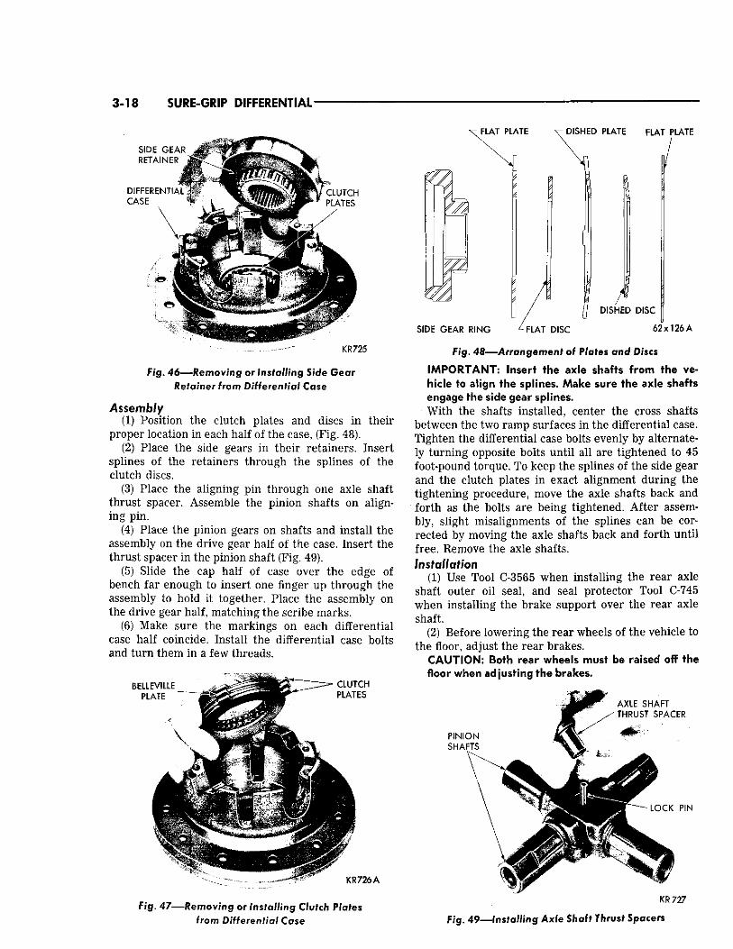
K R 7 2 5
Fig. 46—Removing ©r Installing Side Gem
Retainer from Differential Case
Assembly (1) Position the clutch plates and discs in their
proper location in each half of the case, (Fig. 48). (2) Place the side gears in their retainers. Insert
splines of the retainers through the splines of the clutch discs.
(3) Place the aligning pin through one axle shaft thrust spacer. Assemble the pinion shafts on aligning pin.
(4) Place the pinion gears on shafts and install the assembly on the drive gear half of the case. Insert the thrust spacer in the pinion shaft (Fig. 49).
(5) Slide the cap half of case over the edge of bench far enough to insert one finger up through the assembly to hold it together. Place the assembly on the drive gear half, matching the scribe marks.
(6) Make sure the markings on each differential case half coincide. Install the differential case bolts and turn them in a few threads.
KR726A
Fig. 47—Removing or Installing Clutch Plates from Differential Case
Fig. 48—-Arrangement of Plates and Discs
IMPORTANT: Insert the axle shafts from the vehicle to align the splines. Make sure the axle shafts engage the side gear splines. With the shafts installed, center the cross shafts
between the two ramp surfaces in the differential case. Tighten the differential case bolts evenly by alternately turning opposite bolts until all are tightened to 45 foot-pound torque. To keep the splines of the side gear and the clutch plates in exact alignment during the tightening procedure, move the axle shafts back and forth as the bolts are being tightened. After assembly, slight misalignments of the splines can be corrected by moving the axle shafts back and forth until free. Remove the axle shafts. installation
(1) Use Tool C-3565 when installing the rear axle shaft outer oil seal, and seal protector Tool C-745 when installing the brake support over the rear axle shaft.
(2) Before lowering the rear wheels of the vehicle to the floor, adjust the rear brakes.
CAUTION: Both rear wheels must be raised off the floor when adjusting the brakes.
AXLE SHAFT s THRUST SPACER
KR727
Fig. 49—Installing Axle Shaft Thrust Spacers