REAR AXLE - · PDF fileREAR AXLE - Specifications SERVICE SPECfFlCATlONS Items Standard value...
42
3-1 REAR AXLE CONTENTS NWAA- AXLE ASSEMBLY <2.6L ENGINE> .................. 14 AXLE ASSEMBLY <3.OL ENGINE> .................. 16 AXLE SHAFT ...................................................... 18 DIFFERENTIAL CARRIER ................................... 23 SERVICE ADJUSTMENT PROCEDURES .......... 11 Axle Housing Oil Seal Replacement ...................... 12 Axle Shaft Check for End Play ................................ 11 Gear Oil Level Check .............................................. 11 Limited Slip Differential Preload Measurement .... 12 Rear Axle Total Backlash Check ............................. 1 1 SPECIAL TOOLS ................................................ 5 SPECIFICATIONS ............................................... 2 General Specifications ........................................... 2 Lubricants .............................................................. 4 Sealant and Adhesive ...................................... ..- ... 5 Service Specifications ............................................ 3 Torque Specifications ............................................ 4 TROUBLESHOOTING . .. .. . . . .. . . . . . . .. . . . .. . . . . . .. .. . . . .. . . . 8 AXLE SHAFT, AXLE HOUSING . .. .. ... . ... . ...r_ _____.___.__. 8 Grease Leakage Noise While Wheels are Rotating DIFFERENTIAL (CONVENTIONAL DIFFERENTIAL) .. . .. .. .. . .. ..._..............-....... _ . .. .. _.._ _I... 8 Bearing Noise While Driving or Coasting Constant Noise Gear Noise While Coasting Gear Noise While Driving Heat Noise While Turning Oil Leakage DIFFERENTIAL (LIMITED SLIP DIFFERENTIAL) .. ..__......._ .. .. .. . .._ __.-.- _..______.._..... 9 Abnormal Noise during Driving or Gear Changing Abnormal Noise When Cornering Breakdown Gear Noise Gear Oil Leakage Limited Slip Differential Does not Function Seizure
Transcript of REAR AXLE - · PDF fileREAR AXLE - Specifications SERVICE SPECfFlCATlONS Items Standard value...

3-1
REAR AXLE CONTENTS NWAA-
AXLE ASSEMBLY <2.6L ENGINE> .................. 14
AXLE ASSEMBLY <3.OL ENGINE> .................. 16
AXLE SHAFT ...................................................... 18
DIFFERENTIAL CARRIER ................................... 23
SERVICE ADJUSTMENT PROCEDURES .......... 11 Axle Housing Oil Seal Replacement ...................... 12
Axle Shaft Check for End Play ................................ 11
Gear Oil Level Check .............................................. 11
Limited Slip Differential Preload Measurement .... 12 Rear Axle Total Backlash Check ............................. 1 1
SPECIAL TOOLS ................................................ 5
SPECIFICATIONS ............................................... 2 General Specifications ........................................... 2
Lubricants .............................................................. 4
Sealant and Adhesive ...................................... ..- ... 5
Service Specifications ............................................ 3
Torque Specifications ............................................ 4
TROUBLESHOOTING . . . . . . . . . . . . . . . . . . . . . . . . . . . . . . . . . . . . . . . . 8 AXLE SHAFT, AXLE HOUSING . . . . . . . . . . . . . . ..r_ _____.___.__. 8
Grease Leakage
Noise While Wheels are Rotating
DIFFERENTIAL (CONVENTIONAL DIFFERENTIAL) . . . . . . . . . . . . . .._..............-....... _ . . . . . _.._ _I... 8
Bearing Noise While Driving or Coasting
Constant Noise
Gear Noise While Coasting
Gear Noise While Driving
Heat
Noise While Turning
Oil Leakage
DIFFERENTIAL (LIMITED SLIP DIFFERENTIAL) . . ..__....... _ . . . . . . . .._ __.-.- _..______.._..... 9
Abnormal Noise during Driving or Gear Changing
Abnormal Noise When Cornering Breakdown
Gear Noise
Gear Oil Leakage
Limited Slip Differential Does not Function
Seizure

3-2 REAR AXLE - Specifications
SPECIFICATIONS GENERAL SPECIFICATIONS
items Vehicles with conventional differential
Axle housing type Banjo type Axle shaft
Supporting type Semi-floating type Shaft dimensions
Bearing portion dia. mm (in.) 40 (1.57) Center portion dia. mm (in.) 34.5 (1.358) Overall length mm (in.)
<2.61 Engine> 703.5 (27.700) <3.OL Engine> 723.5 (28.484)
Bearing O.D. x I.D. x width mm(in.) 80 x 40 x 19.75
(3.15 x 1.57 x .7776) Differential
Reduction gear type Hypoid gear Reduction ratio 4.625
Differential lock type Differential geartype and configuration
Side gear Straight bevel gear x 2 Pinion gear Straight bevel gear x 2
Number of teeth Drive gear 37 Drive pinion 8 Side gear
<2.6L Engine> 14 <3.OL Engine> 19
Pinion gear IO
Vehicles with limited slip differential
Banjo type
Semi-floating type
40 ( 1.57) 34.5 (1.358)
703.5 (27.700) 723.5 (28.484)
80x 40 x 19.75 (3.15 x 1.57 x .7776)
Hypoid gear 4.625 Disc type
Straight bevel gear x 2 Straight bevel gear x 4
37 8
16 16 10
/ TSB Revision I
-

REAR AXLE - Specifications
SERVICE SPECfFlCATlONS
Items
Standard value Axle shaft end play mm (in.) Limited slip differential preload (on Vehicle) Nm (ftlbs.)
Parking brake lever stroke Stabilizer attaching bolt end attaching dimension mm (in.) Final drive gear backlash mm (in.)
<2.6L Engine> <3.OL Engine>
Differential gear backlash mm (in.) <2.6L Enigne> <3.OL Engine>
Drive pinion turning torque Without oil seal Nm (in. Ibs.) With oil seal Nm (in. Ibs.)
Difference in total thickness between left and right clutch plates mm (in.) Clearance between the clutch plates and the differential case mm (in.) Difference in distances from backs of left and right pressure rings to end of thrust washer mm (in.) Clearance of the side gear in the axial direction mm (in.) Limited slip differential preload
When equipped with new clutch plates Nm (ft. Ibs.) When equipped with old clutch plates Nm (ft. Ibs.)
Limit Rear axle total backlash mm (in.)
Drive gear runout mm (in.) Differential gear backlash mm (in.) Friction plates and friction discs warpping (flatness) mm (in.) Friction plates and friction discs wear (difference in thicknesses of friction surfaces and projections) mm (in.)
Vehicles with conventional differential
0.05-0.20 (.OOZo-.0079) -
4-6 clicks
15-‘I7 (59~67)
0.1 l-O.16 (.0043-.0063) 0.13-0.18(.0051-.0071)
0.01 O-0.076 (.0004-.0030) O-0.076 (O-.0030)
0.4-0.5 (3.5-4.3) 0.65-0.75 (5.6-6.5)
-
5 (20)
0.05 (.0020) 0.2 (.008)
Vehicles with limited slip differential
0.05-0.20 (.0020-.0079) 35 (25) or more
4-6 clicks
15-17 (.59-.67)
0.1 l-0.16 (.0043-.0063) 0.13-0.18(.0051-.0071)
0.4-0.5 (3.5-4.3) 0.65-0.75 (5.6-6.5) 0.05 (0020) or less
0.06-0.20 (.0024.0079l
0.05 (.0020) or less
0.05-0.20 (.0020-.0079)
65-l 00 (47-72)
35-l 00 (25-72)
5 (20)
0.05 (0020)
0.08 (0031)
0.1 (004)
/ TSB Revision
3-4 REAR AXLE - Specifications
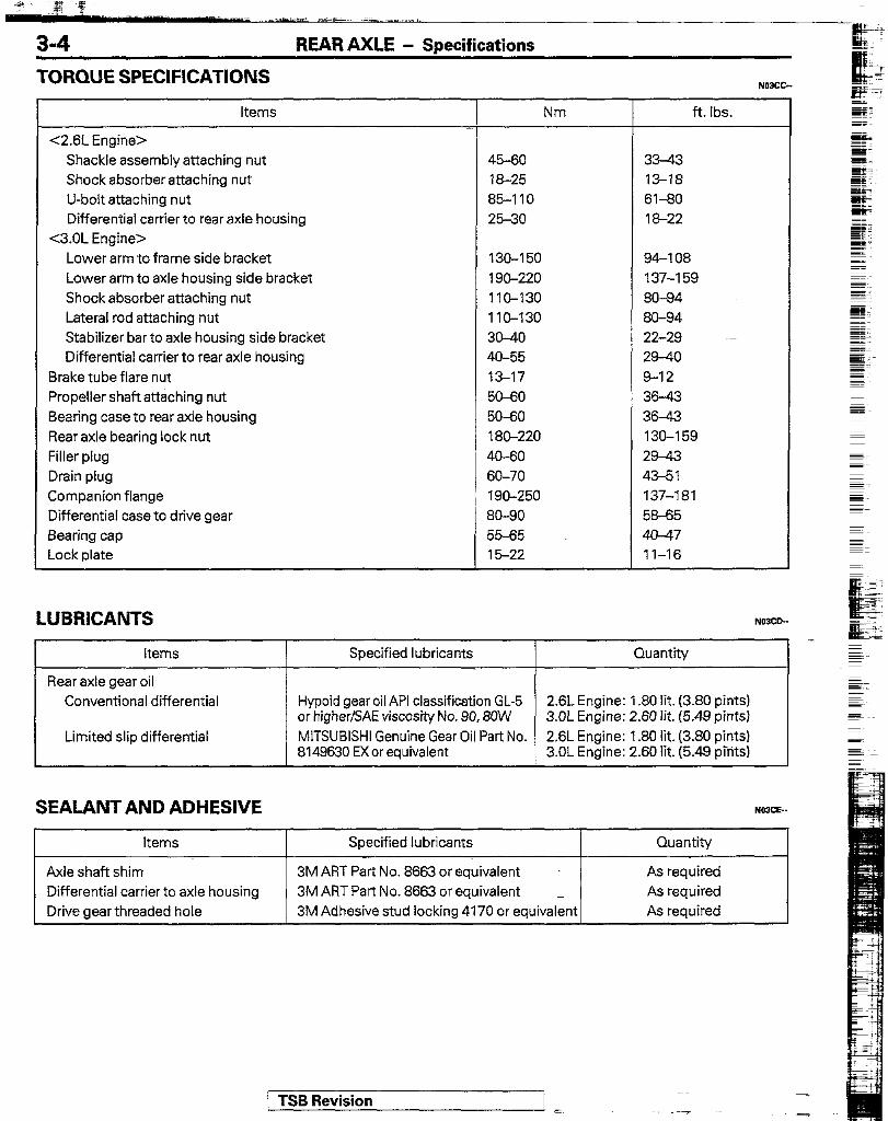
TORQUE SPECIFICATIONS
items
<2.6L Engine> Shackle assembly attaching nut Shock absorberattaching nut U-bolt attaching nut Differential carrier to rear axle housing
<3.OL Engine> Lower arm to frame side bracket Lower arm to axle housing side bracket Shock absorber attaching nut Lateral rod attaching nut Stabilizer bar to axle housing side bracket Differential carrier to rear axle housing
Brake tube flare nut Propeller shaft attaching nut Bearing case to rear axle housing Rear axle bearing lock nut Filler plug Drain plug Companion flange Differential case to drive gear Bearing cap Lock plate
LUBRICANTS
Nm ft. lbs.
45-60 33-43 18-25 13-18 85-110 61-80 25-30 18-22
130-150 94-l 08 1 go-220 137-159 1 IO-130 86-94 1 IO-130 80-94 30-40 22-29 40-55 29-40 13-17 9-12 50-60 36-43 50-60 36-43 189-220 135159 40-60 29-43 60-70 43-51 190-250 137-181 80-90 58-65 55-65 40-47 15-22 11-16
Items Specified lubricants Quantity
Rear axle gear oil Conventional differential
Limited slip differential
Hypoid gear oil API classification GL-5 2.6L Engine: 1.80 lit. (3.80 pints) or higher/SAE viscosity No. 90,8OW 3.OL Engine: 2.60 lit. (5.49 pints) MITSUBISHI Genuine Gear Oil Part No. 2.6L Engine: 1.80 lit. (3.80 pints) 8149630 EXor equivalent 3.OL Engine: 2.60 lit. (5.49 plants)
SEALANT AND ADHESIVE NOJCC-
Items
Axle shaft shim Differential carrier to axle housing Drive gear threaded hole
Specified lubricants
3M ART Part No. 8663 or equivalent 3M ART Part No. 8663 or equivalent 3M Adhesive stud locking 4170 or equivalent
Quantity
As required As required As required
1 TSB Revision
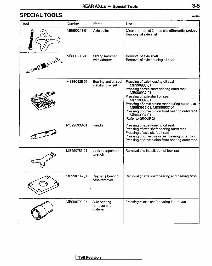
SPECIAL TOOLS
REAR AXLE - Special Tools
Removal of axle shaft
Removal of axle housing oil seal
Pressing of axle shaft bearing outer race MB990937-01
Pressing of axle shaft oil seal MB990937-01
Pressing of drive pinion rear bearing outer race MB990936-01, MB990937-01
Pressing of drive pinion front bearing outer race MB990934-01
Refer to GROUP 2
bearing outer race t bearing outer race
MB990785-01 Lock nut spanner Removal and installation of lock nut wrench
MB990787-01 Rear axle bearing case remover
Removal of axle shaft bearing and bearing case
MB990799-01 Axle bearing Pressing of axle shaft bearing inner race remover and installer
1 TSB Revision

3-6 REAR AXLE - Special Tools
Number Name
M B990339-01 Pinion carrier Removal of side bearing inner race Removal of drive pinion rear bearing inner race
Removal of drive pinion rear bearing inner race
Removal of side bearing inner race Removal of drive pinion rear bearing inner race
MB99081 I-01 Side bearing cup Removal of side bearing inner race remover step plate
Ml3990767-01 Holding of companion flange
MB990901-01
Pressing of d&e pinion rear bearing inner race Pressing of side bearing inner race
1 TSB Revision
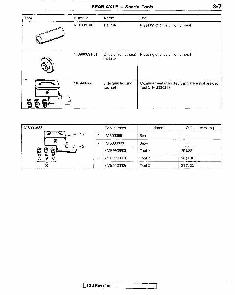
REAR AXLE - Soecial Tools 3-7
1 MB990988 I Tool number 1 1 O.D. mm(h) 1
A B C
Y--
1 1 M8990551 Box -
2 MB990989 Base 2
(MB990990) Tool A 25 t.98)
3 (MB990991) Tool B 28(1.10)
(M B990992) Tool C 31 (1.22)
1 TSB Revision

REAR AXLE - Troubleshooting
TROUBLESHOOTING
Symptom
AXLE SHAFT, AXLE HOUSING
Probable cause Remedy
Noise while wheels Brake drag Replace are rotating Bent axle shaft
Worn or scarred axle shaft bearing __.
Grease leakage Worn or damaged oil seal Replace Malfunction of bearing seal
- DIFFERENTIAL (CONVENTIONAL DIFFERENTIAL)
Constant noise Improper final drive gear tooth contact adjustment Loose, worn or damaged side bearing Loose, worn or damaged drive pinion bearing
Correct or replace
Worn drive gear, drive pinion Worn side gear thrust washer or pinion shaft Deformed drive gear or differential case Damaged gear
Replace
Foreign material Eliminate the foreign material and check; replace if necessary
Gear noise while driving
No oil
Poor gear engagement Improper gear adjustment Improper drive pinion preload adjustment
Fill or change
Correct or replace
Damaged gear
Foreign material
Replace
Eliminate the foreign material and check: replace the parts if necessary
Insufficient oil Fill or change
Gear noise while Improper drive pinion preload adjustment Correct or replace coasting
Damaged gear Replace r
Bearing noise while Cracked or damaged drive pinion rear Replace driving or coasting bearing
Noise while turning Loose side bearing Replace Damaged side gear, pinion gear or pinion shaft
Heat Improper gear backlash Excessive preload
Insufficient oil
Adjust
Fill or change
---- . . 1 TSB Revision

REAR AXLE -Troubleshooting 3-9
Symptom
Oil leakage
DIFFERENTIAL [LIMITED SLIP DIFFERENTIAL)
Abnormal noise during driving or gear changing
NOTE In addition to a malfunction of the differential carrier components, abnormal noise can also be caused by the universal joint of the propeller shaft, the axle shafts, the wheel bearings, etc. Before disassembling any parts, take all possibilities into consideration and confirm the source of the noise.
Probable cause
Clogged breather hose
Cover tightened not Seal malfunction
Worn or damaged oil seal
Excessive oil
Excessive final drive gear backlash Insufficient drive pinion preload
Excessive differential gear backlash
Worn spline of a side gear
Loose spline coupling self-locking nut
Remedy
Clean or replace
Retighten, apply sealant, or replace the gasket
Replace
Adjust the oil level
Adjust
Adjust or replace
Replace
Retighten or replace
Abnormal noise when cornering
Damaged differential gears Damaged pinion shaft Nicked and/or abnormal wear of inner and outer clutch plates Poor gear oil Abnormally worn or damaged thrust washer
Replace
Gear noise
Improper gear oil quantity
Improper final drive gear tooth contact adjustment
Incorrect final drive gear backlash Improper drive pinion preload adjustment
Refill or replace
Adjust or replace
Adjust
NOTE
Damaged. broken, and/or seized tooth surfaces of the drive gear and drive pinion Damaged, broken, and/or seized drive pinion bearings Damaged broken, and/or seized side bearings Damaged differential case Poor gear oil
Improper gear oil quantity
Replace
Refill or replace
Noise from the engine, muffler vibration, transmission, propeller shaft, wheel bearings, tires, body, etc., is easily mistaken as being caused by malfunction in the differential carrier components. Be extremely careful and attentive when performing the driving test, etc. Test methods to confirm the source of the abnormal noise include: coasting, acceleration, constant speed driving, raising the rear wheels on a jack, etc. Use the method most appropriate to the circumstances.
1 TSB Revision 1

REAR AXLE-Troubleshooting
Symptom
Gear oil leakage
Probable cause
Worn or damaged front oil seal, or an improperly installed oil seal Damaged gasket
Remedy
Replace ~~
Loose spline coupling self-locking nut Retighten or replace
T Loose filler or drain plug Retighten or apply adhesive -
Seizure
Clogged or damaged breather hose
Improper final drive gear backlash Excessive drive pinion preload
Clean or replace
Adjust
Excessive side bearing preload Improper differential gear backlash Excessive clutch plate preload
NOTE
Improper gear oil
Improper gear oil quantity
Replace
Refill or replace
In the event of seizure, diassemble and replace the parts involved, and also be sure to check all components for any irregularities and repair or replace as necessary.
Breakdown Incorrect final drive gear backlash Incorrect drive pinion preload Incorrect side bearing preload
7 Adjust -
Excessive differential gear backlash Incorrect clutch plate preload
NOTE
Loose drive gear clamping bolts Retighten
Operational malfunction due to overloaded Avoid excessively rough clutch operation
_
In addition to disassembling and replacing the failed parts, be sure to check all components for irregularities and repair or replace as necessary.
Limited sap The limited slip device is damaged differential does not
Disassemble, check the
function (on snow, functioning, and replace the
mud, ice, etc.). damaged parts
1 TSB RevisionA

REAR AXLE - Service Adiustment Procedures 3-11
I I
llYSO3
\ \ US0671
OQFO12
SERVICE ADJUSTMENT PROCEDUREk’$G
REAR AXLE TOTAL BACKLASH CHECK If the vehicle vibrates and produces a booming sound due to the unbalance of the drivetrain, use the following procedure to measure the rear axle total backlash to see if it is necessary to remove the differential carrier assembly. (I) Park the vehicle on a flat, level surface. (2) Set both the transmission shift lever and the transfer shift
lever to neutral. (3) Chock the wheels.
NOTE If the vehicle is to be raised on a lift, engage the parking brake to lock the wheels.
(4) Manually turn the propeller shaft clockwise as far as it will go and make mating marks on the companion flange dust cover and the gear carrier.
(5) Manually turn the propeller shaft couterclockwise as far as it will go and measure the movement of the mating marks. Limit : 5 mm (.20 in.)
(6) If the backlash exceeds the limit, remove the differential carrier assembly and adjust it.
AXLE SHAFT CHECK FOR END PLAY NOJF3AB 1. Jack up the vehicle and remove the rear wheels. 2. Remove the brake drums. 3. Measure the axle shaft end play with a dial indicator. 4. Pull the axle shaft all the way out and note the end play
indication on the dial indicator. Standard value : 0.05-0.20 mm (.0020-.0079 in.)
5. If the axle shaft end play exceeds the standard value, withdraw the axle shaft, and then adjust to the standard value by changing the shim thickness. (Refer to P.3-18.)
GEAR OIL LEVEL CHECK N03FCAC 1. Remove the filler plug, and check the oil level. 2. The oil level is sufficient if it reaches the level plug hole.
Specified gear oil: Conventional differential Hypoid gear oil API classification GL-5 or higher/SAE viscosity No. 90, 80W
<2.6L Engine> [I.80 lit. (3.80 pints)] <3.OL Engine> [2.60 lit. (5.49 pints)]
Limited slip differential MITSUBISHI Genuine Gear Oil Part No. 8149630 EX or equivalent
<2.6L Engine> [I.80 lit. (3.80 pints11 <3.OL Engine> [2.60 lit. (5.49 pints)]
1 TSB Revision

3-12 REAR AXLE - Service Adjustment Procedures
LlMlTED SLIP DIFFERENTIAL PRELOAD MEA- SUREMENT NC3FDM 1. To measure the preload of the limited slip differential, set
the shift lever of the transmission to the neutral position, lock the front wheels, and fully release the parking brake. One of the rear wheels should be maintained in contact with the ground surface,and the other should be raised
2. Measure the axle shaft turning torque at the side on which the wheel is raised position by using the following procedure: (I) Remove the wheel. (2) Mount the special tool to the hub bolts with the hub
nuts. (3) Find the limited slip differential preload by measuring
the axle shaft turning torque in the forward direction with a torque wrench.
NOTE Before measuring the turning torque, turn the axle shaft to remove any initial resistance.
Standard value : 35 Nm (25 f’tlbs.) or more (4) lf the turning torque is less than the standard value,
remove the limited slip differential from the vehicle and repair it. (Refer to P.337.)
AXLE HOUSING OIL SEAL REPLACEMENT NO3FEAG 1. Disconnect the parking brake cables from the equalizer
and then remove the clamps from the parking brake cables. (Refer to GROUP 5 - Parking Brake Cable.) NOTE Do not disconnect the parking brake cable and rear brake connection.
2. Before disconnecting the brake tube, drain the brake fluid from the bleeder screw at the left side of the rear brake. -1
3. Pull the rear axle shaft with rear brake assembly attached. to remove, the special

REAR AXLE - Service _Adjustment Procedures 3-13
4. Use special tool with hook attached to remove the oil seal.
5. Apply the multipurpose grease to the oil seal fitting area of the rear axle housing.
6. Drive the new oil seal into the rear axle housing end by using the special tools.
7. Apply the multipurpose grease to the oil seal lip. 8. Adjust the clearance between the bearing case and rear
axle housing end. (Refer to P.3-23.) 9. Install the rear axle shaft assembly to the rear axle
housing. IO. Connect the brake tube and bleed out the air. (Refer to
GROUP 5 - Service Adjustment Procedures.) 11. Connect the parking brake cable, and adjust the stroke of
the parking brake lever.
Standard value : 4-6 clicks
(Refer to GROUP 5 - Service Adjustment Procedures.)
1 TSB Revision
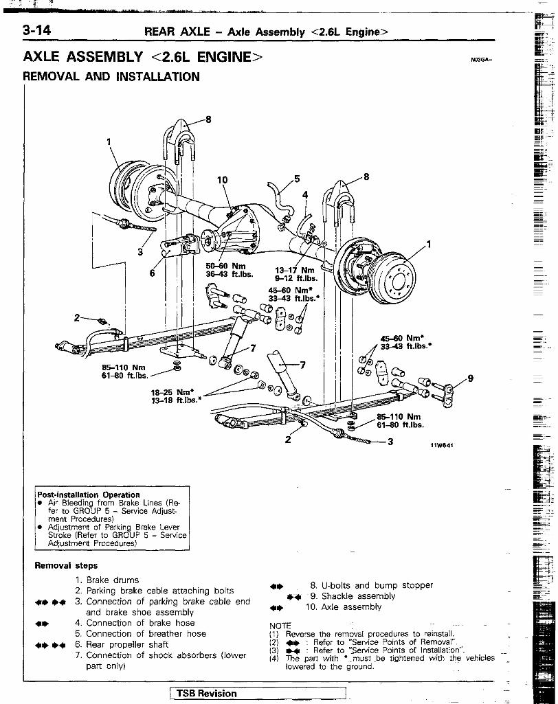
AXLE ASSEMBLY <2.6L ENGINE> REMOVAL AND INSTALLATION
50-60 Nm 36-43 ft.lbs. 13-17’Nm
s-12 ft.lbs. -
l Air Bleeding from Brake Lines (Re-
l Adjustment of Parking Brake Lever Stroke [Refer to GROUP 5 - Service
Removal steps
1. Brake drums 2. Parking brake cable attaching bolts
l * ++ 3. Connection of parking brake cable end and brake shoe assembly
4+ 4. Connection of brake hose 5. Connection of breather hose
+* I)+ 6. Rear propeller shaft 7. Connection of shock absorbers (lower
part only)
45-60 Nm* / 33-43 ft.lbs.*
-3 llW641
4+ 8. U-bolts and bump stopper +‘( 9. Shackle assembly
4+ 10. Axle assembly
NOTE (I) Reverse the removal procedures to reinstall. (2) w : Refer to “Service Points of Removal”. (3) ++ Refer to ‘Service Points of Installation”. 14) The part with *-must be tightened with the vehicles
lowered to the ground.
1 TSB Revision -

REAR AXLE - Axle Assembly <2.6L Engine> 3-15
Inside of vehicle
SERVICE POINTS OF REMOVAL NWGSAF 3. DISCONNECTION OF PARKING BRAKE CABLE END
AND BRAKE SHOE ASSEMBLY Refer to GROUP 5 - Parking Brake Cable.
4. DISCONNECTION OF BRAKE HOSE Before disconnecting the brake tube, drain the brake fluid from the bleeder screw at the right side of the rear brake.
6. REMOVAL OF REAR PROPELLER SHAFT Make the mating marks on the flange yoke of the rear propeller shaft and the companion flange of the differen- tial case.
8. REMOVAL OF U-BOLT AND BUMP STOPPER Before removing the U-bolt and the bumper stopper, place the jack underneath the center of the axle assembly to hold it slightly upward.
10. REMOVAL OF AXLE ASSEMBLY Draw out the axle assembly toward the rear of the vehicle. Caution The axle assembly is unstable on the jack; be careful not to allow it to fall.
SERVICE POINTS OF INSTALLATION NrnCDAF 9. INSTALLATION OF SHACKLE ASSEMBLY
Install the shackle assembly from the outside toward the inside of vehicle.
6. INSTALLATION OF REAR PROPELLER SHAFT Align the mating marks on the flange yoke and the companion flange to install the rear propeller shaft,
3. CONNECTION OF PARKING BRAKE CABLE END AND BRAKE SHOE ASSEMBLY Refer to GROUP 5 - Parking Brake Cable.
pSB Revision

‘?( u --,-- -“-=.-_-eI. _-I ---- i_h_ - -_.-~
3-16 REAR AXLE - Axle Assembly <3.OL Engine>
AXLE ASSEMBLY <3.OL ENGINE> REMOVAL AND INSTALLATION
110-130 Nm 8044 ftlbs
30-40 Nm 22-29 ft.lbs. \ ,
lliLl3f1 Nm
’ ?30-150 Nm i 94-108 ftlbs.
Removal steps
1. Brake drum 2. Parking brake cable attaching bolts
+I, e* 3. Connection of parking brake cable end and brake shoe assembly
4* 4. Connection of brake hose 5. Connection of breather hose
4~ I)+ 6. Rear propeller shaft ++ 7. Stabilizer bar installation bolt
+I) ++ 8. lower arm +* 9. Lateral rod
10. Connection of shock absorbers (lower part only)
l * 11. Axle assembly 12. Coil spring 13. Stabilizer bar
NOTE (1) Reverse the removal procedures to reinstall. (2) *I) : Refer to “Service Points of Removal”. (31 ++ : Refer to “Service Points of Installation”. (4) The part with ‘--must be tightened with the vehicles
lowered to the ground. (5) q : Non-reusable parts.
e=-*
[ TSB Revision _ ~~ I --
_~“.
REAR AXLE - Axle Assembly <3.OL Engine> 3-17
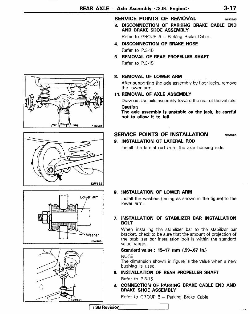
SERVICE POINTS OF REMOVAL N03G.sAo 3. DISCONNECTION OF PARKiNG BRAKE CABLE END
AND BRAKE SHOE ASSEMBLY Refer to GROUP 5 - Parking Brake Cable.
4. DISCONNECTION OF BRAKE HOSE Refer to P.3-15
6. REMOVAL OF REAR PROPELLER SHAFT Refer to P.3-15
12W562
,2W5B3
8. REMOVAL OF LOWER ARM After supporting the axle assembly by floor jacks, remove the lower arm.
11. REMOVAL OF AXLE ASSEMBLY Draw out the axle assembly toward the rear of the vehicle. Caution The axle assembly is unstable on the jack; be careful not to allow it to fall.
SERVICE POINTS OF INSTALLATION Ncl3GclAu 9. INSTALLATION OF LATERAL ROD
Install the lateral rod from the axle housing side.
8. INSTALLATION OF LOWER ARM Install the washers (facing as shown in the figure) to the lower arm.
7. INSTALLATION OF STABILIZER BAR INSTALLATION BOLT When installing the stabilizer bar to the stabilizer bar bracket, check to be sure that the amount of projection of the stabilizer bar installation bolt is within the standard value range. Standard value : 15-17 mm (.5Q-.67 in.) NOTE The dimension shown in figure is the value when a new bushing is used.
6. INSTALLATION OF REAR PROPELLER SHAFT Refer to P.3-15.
3. CONNECTION OF PARKING BRAKE CABLE END AND BRAKE SHOE ASSEMBLY
Refer to GROUP 5 - Parking Brake Cable.
1 TSB Revision

REAR AXLE - Axle Shaft
AXLE SHAFI- REMOVAL AND INSTALLATION
- 1180085
Rear axle shaft shim set
ljD;60 Nm 36-43 ft.lbs.
l Adjustment of Parking Brake Lever
Removal steps
1. Brake drum 2. Parking brake cable attaching bolts
++ I)+ 3. Connection of parking brake cable end and brake shoe assembly
** 4. Connection of brake tubes 5. Nuts
l * 6. Rear axle shaft assembly (with parking brake cable)
7. Shims 8. O-ring
l * Adjustment of axle shaft end play ++ I)+ 9. Lock nut
llW640
+* 10. Lock washer ++ 11. Washer
41) *+ 12, Rear axle shaft *+ 13. Bearing inner race
14. Bearing case *a 15. Oil seal
+I) +a 16. Bearing outer race +I* +* 17. Oil seal
(1) Reverse the removal procedures to reinstall. (2) +* : Refer to “Service Points of Removal”. (3) ** : Refer to “Service Points of Installation”. (4) m : Non-reusable parts
/ TSB Revision
REAR AXLE - Axle Shaft 3-19
I 1 I I
MB99078501 \ I I I
1 TSB Revision
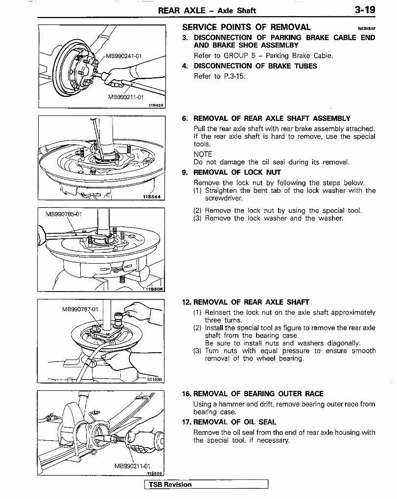
SERVICE POINTS OF REMOVAL NDWBAF 3. DISCONNECTION OF PARKING BRAKE CABLE END
AND BRAKE SHOE ASSEMLBY
Refer to GROUP 5 - Parking Brake Cable. 4. DISCONNECTION OF BRAKE TUBES
Refer to P.3-15.
6. REMOVAL OF REAR AXLE SHAFT ASSEMBLY Pull the rear axle shaft with rear brake assembly attached. If the rear axle shaft is hard to remove, use the special tools. NOTE Do not damage the oil seal during its removal.
9. REMOVAL OF LOCK NUT Remove the lock nut by following the steps below. (I) Straighten the bent tab of the lock washer with the
screwdriver.
(2) Remove the lock nut by using the special tool. (3) Remove the lock washer and the washer.
12. REMOVAL OF REAR AXLE SHAFT (1) Reinsert the lock nut on the axle shaft approximately
three turns. (2) install the special tool as figure to remove the rear axle
shaft from the bearing case. Be sure to install nuts and washers diagonally.
(3) Turn nuts with equal pressure to ensure smooth removal of the wheel bearing.
16. REMOVAL OF BEARING OUTER RACE Using a hammer and drift, remove bearing outer race from bearing case.
17. REMOVAL OF OIL SEAL Remove the oil seal from the end of rear axle housing with the special tool, if necessary.
3-20 REAR AXLE - Axle Shaft
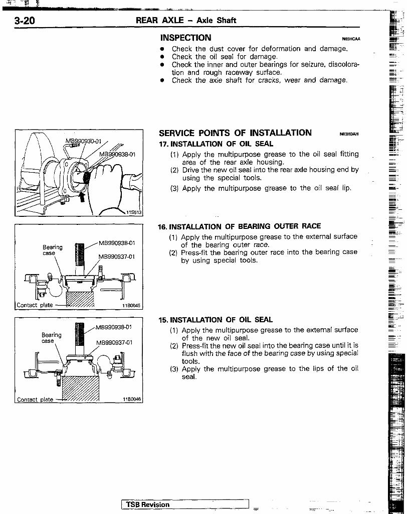
INSPECTION NWHCAA
l Check the dust cover for deformation and damage. l Check the oil seal for damage. l Check the inner and outer bearings for seizure, discolora-
tion and rough raceway surface. e Check the axle shaft for cracks, wear and damage.
Bearing case
\
MB99093801
MB990937-01 /
SERVICE POINTS OF INSTALLATION NOQHDAH 17. INSTALLATION OF OIL SEAL
(1) Apply the multipurpose grease to the oil seal fitting area of the rear axle housing.
(2) Drive the new oil seal into the rear axle housing end by using the special tools.
(3) Apply the multipurpose grease to the oil seal lip.
16. INSTALLATION OF BEARING OUTER RACE (1) Apply the multipurpose grease to the external surface
of the bearing outer race. (2) Press-fit the bearing outer race into the bearing case
by using special tools.
15. INSTALLATION OF OIL SEAL (1) Apply the multipurpose grease to the external surface
of the new oil seal. (2) Press-fit the new oil seal into the bearing case until it is
flush with the face of the bearing case by using special tools.
(3) $.py the multipurpose grease to the lips of the oil
1 TSB Revision

’ REAR AXLE - Axle Shaft 3-21
13.lfS~~U&I$N OF BEARING INNER RACE/IS. REAR
(1) Apply the multipurpose grease to the roller surfaces of the bearing inner race.
(2) Install the rear brake assembly attached with bearing case and the bearing inner race in that order to the axle shaft.
(3) Press-fit the bearing inner race into the axle shaft by using special tool.
(4) Pack the bearing case with the multipurpose grease.
11. INSTALLATION OF WASHER/IO. LOCK WASHER/S. LOCK NUT
Install these parts with cares described below. (I) Apply the multipurpose grease to the thread portion of
the axle shaft, to which the locking nut is installed. (2) Align the washer tab with the slot of the axle shaft to
install the washer. (3) Align the lock washer tab with the slot of the axle shaft
to install the lock washer as figure. (4) Install the lock nut with its chamfering in the directions
shown in the illustration.
(5) Tighten the lock nut to the specified torque by using the special tool.
(6) Bend the tab of the lock washer into the slot of the lock nut.
NOTE If the slot in the lock nut and the tab of the lock washer are out of alignment, turn the lock nut in until they are in alignment.
Sevision

3-22 REAR AXLE - Axle Shaft
. ADJUSTMENT OF AXLE SHAFT END PLAY Adjust the clearance between the bearing case and rear axle housing end by the-following procedure. (1) Insert a 1 mm (.04 in.) thick shim and O-ring into the ~~
left side rear axle housing. (2) Apply the specified sealant to the mating surface of _
bearing case, install the left axle shaft into rear axle housing and tighten the nuts.
NOTE Tighten the nuts in diagonal sequence.
Specified sealant: 3M ART Part No. 8663 or equivalent
(3) Install the right axle shaft without a shim (s) and O-ring and temporarily tighten to about 6 Nrn- (4.3 ft.Ibs.).
(4) Measure the clearance-between the bearing case and rear axle housing end with a feeler gage.
(5) Select shims of the thickness which is equal to the sum of the measured clearance and 0.05-0.20 mm (.0020-.0079 in.)
(6) Remove the right axle shaft, and install shim (s) and 0- = ring on the right side-rear axle housing end.
. (7) Apply the specified sealant to the mating surface of bearing case, install the right axle shaft into rear axle housing and tighten the nut.
Specified sealant: 3M ART Part No. 8663 or equivalent
NOTE Tighten the nuts in diagonal sequence.
(8) Check to assure that the axle shaft axial play is within the standard value.
Standard value : 0.06420 mm (.0020-.0079 in.)
3. CONNECTION OF PARKING BRAKE CABLE END AND BRAKE SHOE ASSEMBLY Refer to GROUP 5 - Parking Brake Cable.
! TSB Revision 1

REAR AXLE - Dikrential Carrier
DIFFERENTIAL CARRIER REMOVAL AND INSTALLATION
50-60 Nm 13-17 Nm 35-43 ft.lbs. 9;12 ft.lbs
40-50 Nm 2-3 ft.lbs.
Pre-removal Operation l Drain of Differential Gear Oil
Post-installation Operation 0 Air Bleeding from Brake Lines (Fie-
fer to GROUP 5 - Service Adjust- ment Procedures)
0 Adjustment of Parking Brake Lever Stroke (Refer to GROUP 5 - Service Adjustment Procedures)
l Filling of Differential Gear Oil (Refer to P.3-Il.)
Removal steps 1. Brake drums 2. Parking brake cable attaching bolts *+ I)+ 7. Rear propeller shaft
41, ,+ 3. Connection of parking brake cable end +I) I)* 6. Differential carrier and brake shoe assembly
4* 4. Connection of brake tubes NOTE
5. Nuts (1) Reverse the removal procedures to reinstall. (2) +e : Refer to “Service Points of Removal”.
4* 6. Rear axle shaft assembly (3) I)* : Refer to “Service Points of Installation”.
SERVICE POINTS OF REMOVAL NOJIeAF 3. DISCONNECTION OF PARKING BRAKE CABLE END
AND BRAKE SHOE ASSEMBLY Refer to GROUP 5 - Parking Brake Cable.
1 TSB Revision

3-24 REAR AXLE - Differential Carrier
MB990241-01
4.
6.
7.
8.
DISCONNECTION OF BRAKE TUBES Refer to P.3-15. REMOVAL OF REAR AXLE SHAFT ASSEMBLY Pull out the right and left axle shafts by about 70 mm (2.8 in.). If it is hard to pull out, use the special tools.
REMOVAL OF REAR PROPELLER SHAFT Refer to P.3-15.
REMOVAL OF DIFFERENTIAL CARRIER Remove the attaching nuts and strike the lower part of differential carrier assembly with a square lumber several times, to remove the assembly. Caution (1) Do not remove the uppermost nut but keep it
loosened all the way to the stud bolt end. (2) Use care not to strike the companion flange.
SERVICE POINTS OF INSTALLATION N00,DAF 8.
7.
3.
APPLlCATlON OF SEALANT TO DIFFERENTIAL CARRI- ER When the differential carrier is installed, apply specified sealant to the differential carrier mounting surface of the axle housing as illustrated in either of the illustrations. :
Specified sealant: 3M ART Part No. 8663 or equivalent
INSTALLATION OF REAR PROPELLER SHAFT Refer to P.3-15. CONNECTION OF PARKING BRAKE CABLE END AND BRAKE SHOE ASSEMLBY Refer to GROUP 5 - Parking Brake Cable.
1 TSB Revision I:

REAR AXLE - Differential Carrier 3-25
INSPECTION BEFORE DISASSEMBLY MWEAA Secure the working base in a vice and then install the removed differential carrier assembly.
FINAL DRIVE GEAR BACKLASH With the drive pinion locked in place, measure the final drive gear backlash with a dial indicator on the drive gear.
NOTE Measure at four points or more on the circumference of the drive gear. Standard value :
<2.6L Engine> 0.1 l-0.16 mm (.0043-.0063 in.)
<3.OL Engine> 0.13-0.18 mm (.0051-.0071 in.)
DRIVE GEAR RUNOUT Measure the drive gear runout at the shoulder on the reverse side of the drive gear. Limit : 0.05 mm (.0020 in.)
DIFFERENTIAL GEAR BACKLASH (CONVENTIONAL DIF- FERENTIAL) While locking the side gear with the wedge, measure the differental gear backlash with a dial indicator on the pinion gear. Standard value :
<2.6L Engine> 0.010-0.076 mm (.0004-.0030 in.)
<3.OL Engine> O-0.076 mm (O-.0030 in.)
Limit : 0.2 mm (.008 in.) FINAL DRIVE GEAR TOOTH CONTACT Check the final drive gear tooth contact by following the steps below. (I) Apply a thin, uniform coat of machine blue to both
surfaces of the drive gear teeth.
1 TSB Revision I

3-26 REAR AXLE - Differential Carrier
(2) Insert a brass rod between the differential carrier and the .._ differential case, and then rotate the companion flange by
_ miL
hand (once in the normal direction, and then once in the E. reverse direction) while applying a load to the drive gear, so that the revolution torque [appro::imately 2.5-3.0 Nm
g.- S&
(1 B-2.2 ft.lbs.)I is aoolied to the drive pinion.
Caution If the drive gear is rotated too much, the tooth contact pattern will become unclear and difficult to check.
(3) Check the tooth-contact condition of the drive gear and drive pinion.
NOTE Checking the tooth contact pattern is the way to confirm that the adjustments of the pinion height and backlash have been done properly. Continue to adjust the pinion height and backlash until the tooth contact pattern resem- bles the standard pattern. If, after adjustments have been made, the correct tooth contact pattern cannot be obtained, it means that the drive gear and the drive pinion have become worn beyond the allowable limit. Replace the gear set.
Caution If either the drive gear or the drive pinion is to be replaced, be sure to replace both gears as a set.
( TSB Revision

REAR AXLE - Differential Carrier 3-27
Standard tooth contact pattern
1 Toe 2 Drive-side 3 Heel 4 Coast-side
Problem
Tooth contact pattern resulting from excessive Pin- ion height
Solution
The drive pinion is positioned too far from the center of the drive gear.
Increase the thickness of the pinion height adjusting shim, and position the drive pinion closer to the center of the drive
%:I for backlash adjustment, position the drive gear farther from the drive pinion.
Tooth contact pattern resulting from insufficient pinion height
The drive pinion is positioned too close to the center of the drive gear.
Decrease the thickness of the pinion height adjusting shim, and position the drive pinion farther from the center of the drive gear. Also, for backlash adjustment, position the drive gear closer to the drive pinion.
llS642
, TSB Revision

-y-> 7” g
3-28 REAR AXLE - Differential Carrier
DISASSEMBLY
<Conventional type> (Refer to P.3-25.1
. Final Drive Gear Tooth Contact (Re- fer to P.3-25.1
Disassembly steps
1. Lock plates +* 2. Side bearing nuts
3. Bearing caps +* 4. Differential case assembly
5. Side bearing outer races +* 6. Side bearing inner races
7. Bolts (10) 4* 8. Drive gear 4* 9. Lock pin
10. Pinion shaft 11. Thrust block 12. Pinion gears 13. Pinion washers 14. Side gears 15. Side gear thrust spacers 16. Differential case
<Conventional differential>
18
118546
\ 7
llBOlZ4
20. Drive pinion assembly 21. Drive pinion front shim (for preload
adjustment) 22. Drive pinion spacer 23. Drive pinion rear bearing inner race 24. Drive pinion rear shim (for pinion height
adjustment) 25. Drive pinion 26. Companion flange 27. Oil seal 28. Drive pinion front bearing inner r&e 29. Drive pinion front bearing outer race 30. Drive pinion rear bearing outer race 31. DifferentEl carrier
+* 17. Limited slip differential case assembly 18. Self-locking nut
NOTE (1) +II) : Refer to “Service Points of Disassembly”.
19. Washer (2) 0 : Non-reusable parts
( TSB Revision

REAR AXLE - Differential Carrier 3-29
SERVICE POINTS OF DISASSEMBLY PJo31- 2. REMOVAL OF SIDE BEARING NUT
Using the special tool, remove the side bearing nut.
4. REMOVAL OF DIFFERENTIAL CASE ASSEMBLY Take out the differential case assembly with hammer handles. NOTE Keep the right and left side bearings and side bearing nuts separate, so that they do not become mixed at the time of reassembly.
6. REMOVAL OF SIDE BEARING INNER RACE Pull out the side bearing inner races by using the special tools.
8. REMOVAL OF DRIVE GEAR (1) Make the mating marks to the differential case and the
drive gear. (2) Loosen the drive gear attaching bolts in diagonal
sequence to remove the drive gear.
9. DRIVE-OUT OF LOCK PIN Drive out the lock pin with a punch. NOTE The removed side gears and side gear thrust spacers, left and right, should be retained for reassembly.
[ TSB Revision

I~ .-,.. ^” --_..,_ ---emsa cI _=_
REAR AXLE - Differential Carrier
MIT303173
18. REMOVAL OF SELF-LOCKING NUT Use the special tool to hold the companion flange and remove the companion flange self-locking nut.
20. REMOVAL OF DRIVE PINION ASSEMBLY (1) Make the mating marks to the driie pinion and
companion flange. Caution The mating mark made on the companion flange must not be on the coupling surface of the flange yoke and the rear propeller shaft.
(2) Drive out the drive pinion together with the drive pinion spacer and drive pinion front shims.
23. REMOVAL OF DRIVE PINION REAR BEARING INNER RACE Pull out the drive pinion rear bearing inner race by using the special tools.
-
29. REMOVAL OF DRIVE PINION FRONT BEARING OUTER RACE/30. DRIVE PINION REAR BEARING OUTER RACE Drive out the drive pinion front bearing outer race from the _ gear carrier.
INSPECTION NOJIHAC Wash the disassembled pa& in cleaning solvent, dry them using compressed air, and then check the following areas: __ l Check the companion flange for wear or damage. l Check the oil seal for wear or deterioration. l Check the bearings for wear or discoloration. l Check the gear carrier for cracks. o Check the drive pinion and ring gear for wear or cracks. 1 o Check the side gears, pinion gears and pinion shaft for
wear or damage. <conventional type>
l Check the side gear spline for wear or damage. <conven- : tjonal type>
[ TSB Revision _I

REAR AXLE - Differential Carrier
REASSEMBLY <Conventional differential>
Xi-22 Nm
lh-260 Nm 137-181 ft.lbs.
<Limited slip differential> 16-22 Nm llW546
3P 3J 71-16 ft.lbs.
-
<Conventional differential>
17 18 18 20
Differential gear set Final drive gear set
14 4 2?
Reassembly steps
1. Differential carrier I)+ 2. Drive pinion rear bearing outer race +a 3. Drive pinion front bearing outer race +4 Adjustment of pinion height
4. Drive pinion 5. Drive pinion rear shim (for pinion height
adjustment) 6. Drive pinion rear bearing inner race
l 4 Adjustment of drive pinion preload 7. Drive pinion front bearing inner race 8. Oil seal 9. Drive pinion front shim (for preload
adjustment) 10. Drive pinion spacer 11. Drive pinion assembly 12. Companion flange 13. Washer
17. Side gear thrust spacers 18. Side gears 19. Pinion washers 20. Pinion gears
I)+ Adjustment of differential gear backlash 21. Thrust block 22. Pinion shaft
e+ 23. Lock pin l 4 24. Drive gear
25. Bolts (IO) ++ 26. Side bearing inner races
27. Side bearing outer races 28. Differential case assembly
w+ 29. Bearing caps l 4 Adjustment of final drive gear backlash
30. Side bearing nuts 31. Lock plates
14. Self-locking nut 15. Differential case NOTE
16. Limited slip differential case assembly (1) 1)4 : Refer to “Service Points of Reassembly”. (2) q : Non-reusable parts
[ TSB Revision -I

3-32 REAR AXLE - Differential Carrier
MB990937-01
llYO5s
MB99093801
I I MB99093441
/
MB990905-310 MB9909052-01 ~MB990901-01
MB990905101
SERVICE POINTS OF REASSEMBLY 2. INSTALLATION OF DRIVE PINION REAR BEARING
w Ir-
OUTER RACE =i _ _I Press-fit the drive pinion rear bearing outer race into the gear carrier by using special tools.
NOTE Z.T~ -:
Perform press-fitting carefully so as not to tilt the outer s. race. mF
z =zr WY :
3. INSTALLATION OF DRIVE PINION FRONT BEARING E’ I
OUTER RACE si pz- r E -.
Press-fit the drive pinion front bearing outer race into gear carrier by using special tools.
g;.:
355 rc:, z
NOTE Perform press-fitting carefully so as not to tilt the outer race.
a ADJUSTMENT OF PINION HEIGHT Adjust the drive pinion height by the following proce- dures: (I) Install special tools and drive pinion front and rear
bearing inner races to the gear carrier in the sequence shown in the illustration. For vehicles with 3.OL Engine, fit in an attachment with a thickness of 15 mm (.59 in.) above MB996820-01.
(2) Tighten tfie nut of the special tool until the standard value of drive pinion turning torque is obtained.
(3) Measure the drive pinion turning torque (without the oil seal).
Standardvalue : W-O.5 Nm (3.5-4.3 in.lbs.)
NOTE 1. Gradually tighten the nut of the special tool while
checking the drive pinion turning torque. 2. Because one rotation cannot be made when the
special tool is in contact with the gear carrier, move it a few times and, after seating the bearing, measure the rotation torque.
1 TSB Revision 1

REAR AXLE - Differential Carrier 3-33
(4) Position the special tool in the side bearing seat of the gear carrier, and then select a drive pinion rear shim of a thickness which corresponds to the gap between the special tools.
NOTE Be sure to clean the side bearing seat thoroughly. When positioning the special tool, be sure that the cut- out sections of the special tool are in the position shown in the illustration, and also confirm that the special tool is in close contact with the side bearing seat. When selecting the drive pinion rear shims, keep the number of shims to a minimum.
(5) Fit the selected drive pinion rear shim(s) to the drive pinion, and press-fit the drive pinion rear bearing inner race by using the special tool.
. ADJUSTMENT OF DRIVE PINION PRELOAD Adjust the drive pinion turning torque by using the following procedure:
Without Oil Seal (1) Fit the drive pinion front shim(s) between the drive
pinion spacer and the drive pinion front bearing inner race.
(2) Tighten the companion flange to the specified torque by using the special tools.
NOTE Do not install the oil seal.
(3) Measure the drive pinion turning torque (without the oil seal)
Standard value : 0.4-0.5 Nm (3.54.3 in.lbs.)
(4) If the drive pinion turning torque is not within the range of the standard value, adjust the turning torque by replacing the drive pinion front shim(s) or the drive pinion spacer.
NOTE When selecting the drive pinion front shims, if the number of shims is large, reduce the number of shims to a minimum by selecting the drive pinion spacers.
(5) Remove the companion flange and drive pinion once again.
1 TSB Revision

, ‘Kf * 3 #&
z- = L ‘-~--‘-- .l___i _ _ _~
3-34 REAR AXLE - Differential Carrier
llY223
1 TSB Revislon
Wiih Oil Seal (1) After setting the drive pinion front bearing inner race,
drive the oil seal into the gear carrier front lip by using the special tool.
(2) Apply multipurpose grease to the oil seal lip.
(3) Install the drive pinion assembly and companion flange with mating marks properly aligned, and tighten the companion flange self-locking nut to the specified torque by using the special tools.
(4) Measure the drive pinion turning torque (with oil seal) to verify that the drive pinion turning torque complies with the standard value.
Standard value : 0.65475 Nm (5.6-6.5 in.lbs .I
l ADJUSTMENT OF DIFFERENTIAL GEAR BACKLASH (1) Assemble the side gears, side gear thrust spacers,
pinion gears, and pinion washers into the differential case.
(2) Temporarily install the pinion shaft. L NOTE
=
Do not drive in the lock pin yet.
(3) [nsert a wedge between the side gear and the pinion shaft to lock the side gear.
(4) While locking the side gear with the wedge, measure 1 the differential gear backlash with a dial indicator on ~=_ the pinion gear. Standard value :
<2.6L Engine> 0.010-0.076 mm (.0004-.0030 in.)
<3.OL Engine> O-O.076 mm (O-.0030 in.)
Limit : 0.2 mm (.008 in.) --- - . _ I

REAR AXLE - Differential Carrier 3-35
(5) If the differential gear backlash exceeds the limit, adjust the backlash by installing thicker side gear thrust spacers.
(6) Measure the differential gear backlash once again, and confirm that it is within the limit. If adjustment is not possible, replace the side gears and pinion gears as a set.
23. INSTALLATION OF LOCK PIN (1) Align the pinion shaft lock pin hole with the differential
case lock pin hole, and drive in the lock pin. (2) Stake the lock pin with a punch at two points.
24. INSTALLATION OF DRIVE GEAR
(1) Clean the drive gear attaching bolts. (2) Remove the adhesive adhered to the threaded holes
of the drive gear by turning the tap tool (Ml0 x 1.25), and then clean the threaded holes by applying com- pressed air.
(3) Apply the specified adhesive to the threaded holes of the drive gear.
Specified adhesive : 3M adhesive stud locking 4170 or equivalent
(4) Install the drive gear onto the differential case with the mating marks properly aligned. Be sure to tighten the bolts to the specified torque in a diagonal sequence.
26. PRESS-FIT OF SIDE BEARING INNER RACE Press-fit the side bearing inner races to the differential case by using the special tool.
29. INSTALLATION OF BEARING CAP Align the mating marks on the gear carrier and the bearing cap, and then tighten the bearing cap.
1 TSB Revision

REAR AXLE - Differential Carrier
MB990201-01
When backlash is in- r sufficient
I IWhen bad&h is ex- J I
k MB990201-01 w
MB092153 MB0921 54
. ADJUSTMENT OF FINAL DRIVE GEAR BACKLASH
(1) Using the special tool, temporarily tighten the side bearing nut until it is in the state just before preloading of the side bearing.
(2) Measure the final drive gear backlash.
Standard value : <2.6L Engine>
0.11-0.16 mm (.0043-.0063 in.) <3.OL Engine>
0.13418 mm (.0051-.0071 in.)
(3) Using the special tool (MB990201 I, adjust the backlash to standard value by moving the side bearing nut as shown. NOTE First turn the side bearing nut for loosening, and then turn (by the same amount) the side bearing nut for tightening.
(4) Using the special tool: to apply the preload, turn down both right and left side bearing nuts on half the distance between centres of two neighbouring holes.
(5) Choose and install the lock plates (two kinds).
[ TSB Revision
REAR AXLE - Differential Carrier 3-37
(6) Check the final tooth contact. If poor contact is evident, make adjustment. (Refer to P.3-25.)
(7) Measure the drive gear runout.
Limit : 0.05 mm (.0020 in.)
If the drive gear runout exceeds the limit, reinstall by changing the phase of the drive gear and differential case, and remeasure.
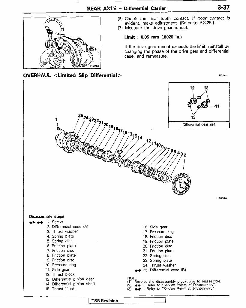
OVERHAUL <Limited Slip Differential >
Disassembly steps l * I)* 1. Screw
2. Differential case (A) 3. Thrust washer 4. Spring plate 5. Spring disc 6. Friction plate 7. Friction disc 8. Friction plate 9. Friction disc
10. Pressure ring 11. Side gear 12. Thrust block 13. Differential pinion gear 14. Differential pinion shaft 15. Thrust block
16. Side gear 17. Pressure ring 18. Friction disc 19. Friction plate 20. Friction disc 21. Friction plate 22. Spring disc 23. Spring plate 24. Thrust washer
I)+ 25. Differential case (B)
NOTE (1) Reverse the disassembly procedures to reassemble. (2) +e : Refer to “Service Points of Disassembly”. (3) .4 : Refer to “Service Points of Reassembly”.
/ TSB Revision

.‘?, .T ..jp 8 ~------ - --~ ~=_. _~
3-38 REAR AXLE - Differential Carrier
Q 0 The strong contact on-the inner circumference of the -1
115659 friction surface is because of the spring plate and the spring disc; this wear is not abnormal.
1 TSB Revision
SERVICE POINTS OF DISASSEMBLY hwwlb. 1. REMOVAL OF SCREW
(1) Loosen screws of the differential cases (A) and (B) uniformly a little at a time.
(2) Separate differential case (A) from differential case (B).
NOTE Before disassembling the differential cases. confirm _ that the mating marks (numbers) on case A and case B are the same.
(3) Remove the components from differential case(B).
NOTE Keep the right and left thrust washers, spring plates, spring discs, friction plates, and friction discs separate in order to be able to distinguish them for reassembly.
INSPECTION No31a4A e Check the side gears, pinion gears and pinion shaft for
wear or damage. e Check the side gear spline for wear or damage.
INSPECTION OF CONTACT AND SLIDING SURFACES OF PARTS (1) Inspect the friction plate, friction disc, spring plate, spring
disc and pressure ring. A The friction surfaces ofthe friction plate, friction disc,
spring plate, and spring disc. If there are any signs of seizure, severe friction, or color change from the heat, it will adversely affect the locking performance; replace the part with a new one.
NOTE The strong contact on the inner circumference of the friction surfaces is because of the spring plate and the spring disc; this wear is not abnormal.
B The six projections on the inner circumference of the friction disc. If there are nicks and dents, it will cause abnormalities in the clutch pressure. Repair the parts by using an oil stone; if the parts cannot be repaired, replace them.
C The four projections on the outer circumference of the friction disc. If there are nicks and dents, it will cause abnormalities in the clutch pressure. Repair the parts by using an oil stone; if the parts cannot be repaired, replace them.
D The friction surface of the friction disc of the pressure ring. If there are nicks or scratches, repair the part by first grinding with an oil stone and then polishing with rubbing compound on a surface plate.
NOTE -
(2) Inspect the contact and sliding surfaces listed below, and 0 repair any nicks and burrs by using an oil stone.
G E The sliding surfaces of the thrust washer and the case. F The spring contacting surface of the differential case.
F G The contact surfaces of the outer circumference of the
E pressure ring and the inner circumference of the differential case.
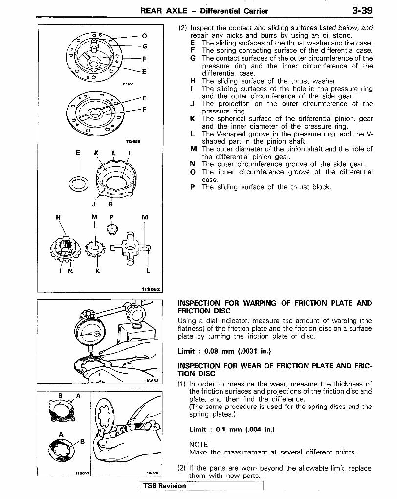
REAR AXLE - Dhferential Carrier 3-39
H The sliding surface of the thrust washer. I The sliding surfaces of the hole in the pressure ring
and the outer circumference of the side gear. J The projection on the outer circumference of the
pressure ring. K The spherical surface of the differential pinion. gear
and the inner diameter of the pressure ring. L The V-shaped groove in the pressure ring, and the V-
shaped part in the pinion shaft. M The outer diameter of the pinion shaft and the hole of
the differential pinion gear. N The outer circumference groove of the side gear. 0 The inner circumference groove of the differential
case. P The sliding surface of the thrust block.
E K L I
j d H M P M
i ti Ii i
llS662
INSPECTION FOR WARPING OF FRICTION PLATE AND FRICTION DISC Using a dial indicator, measure the amount of warping (the flatness) of the friction plate and the friction disc on a surface plate by turning the friction plate or disc.
Limit : 0.08 mm (.0031 in.)
INSPECTION FOR WEAR OF FRICTION PLATE AND FRIC- TION DISC (1) In order to measure the wear, measure the thickness of
the friction surfaces and projections of the friction disc and plate, and then find the difference. (The same procedure is used for the spring discs and the spring plates.)
Limit : 0.1 mm (.004 in.)
NOTE Make the measurement at several different points.
(2) If the parts are worn beyond the allowable limit, replace them with new parts.
1 TSB Revision I

REAR AXLE - Differential Carrier
SERVICE POINTS OF REASSEMBLY NoJ,RlC 25. INSTALLATION OF DIFFERENTIAL CASE (B)
Before assembly, use the following method to adjust the clearance between the spring plates and differential cases (for adjustment of the clutch plate friction force). and to adjust the axial clearance of the side gear when installing the internal components into the differential case.
(1)Arrange the two (each) friction discs and friction plates for each side, one on top of another, as shown in the figure, combining them so that the difference in thickness between the left and the right is the standard value.
Standard value : 0.05 mm (.0020 in.) or less
NOTE For new ones, there is one type of friction plate: 1.75 mm (0689 in.); there are two types of friction disc: 1.75 mm (.0689 in.) and-l.85 mm (0728in.).
(2)Arrange one spring disc and one spring plate for each side, one on top of the other, so that the difference between the left and the right thickness is minimized.
NOTE For new ones, there is one type of spring disc and spring plate: 1.75 mm (0689 in.).
(3)Assemble the pressure ring’s internal components (differential pinion shaft and pressure ring) and the friction discs and friction plates, and then, as shown in the figure, measure the overall width.
(4Kalculate the total value (C) of the thickness of the spring discs and spring plates plus the value measured in (3) above.
(5)Obtain the dimension (D) between the spring plate contact surfaces when differential cases (A) and (B) are combined. (D=E+F-G)
(6)Change the thickness of the friction disc so that the clearance (D - C) between the differential case and the spring plate becomes the standard value.
Standard value : 0.05420 mm (.0024-.0079 in.)
j TSB Revision

REAR AXLE - Differential Carrier 3-41
Thrust washer
.*..--a
,
(7)Remove the spring plates, spring discs, friction plates and friction disc.
(8)lnstall the thrust washer as shown in the figure, and then select a thrust washer so that the difference between the left and right dimensions from the pressure ring rear face to the thrust washer end face is the standard value.
Standard value : 0.05 mm (.0020 in.) or less
NOTE Measure the distance while squeezing the V-shaped groove manually.
(9)Measure the dimension (H) from the thrust washer end surafce to end surafce.
(10)Obtain the dimension (I) between the thrust washer contact surfaces when differential cases (A) and (B) are combined. (I=J+K+L)
NOTE Dimension J is the distance between the spring plate contact surfaces when differential cases (A) and (B) are combined. (Refer to P.340.)
(1 l)Change the thickness of the thrust washer so that the clearance ( I - H ) between the thrust washer and the differential case is the standard value.
Standard value : 0.05420 mm (.0020-.0079 in.)
NOTE 1. Select the thrust washer so that the difference
between the left and right dimensions from the pressure ring rear face and the thrust washer end surface are the standard value even when the thrust washer is changed.
2. There are three sizes of new thrust washers: 1.50 mm (0591 in.), 1.60 mm (.0630 in.), and 1.70 mm (.0670 in.)
(12)Place the each part in the differential case (B) as directions shown in the figure.
NOTE 1. Before assembly, apply the specified gear oil to
each component especially careful to coat contact surfaces and sliding surfaces.
Spring plate
jTSB Revision

REAR AXLE - Differential Carrier
Specified gear oil: MOPAR Hypoid Gear Lubricant Part No. 4318058 plus MOPAR Hypoid Gear Oil Additive-Friction Modi- fier, Part No. 4318060 or equivalent
2. Be careful not to -insert the friction plates and friction discs in the incorrect order and to install the spring plates and spring disc in incorrect direction.
1. INSTALlATlON OF SCREW (1) Align the mating marks (the same numeral on each ~_
case) of differential case (A) and differential case (B). (2) Turning the screwdriver slowly several times, tighten
the screw so that the-cases are in close contact.
NOTE If, even though the screw is tightened, the end surfaces of case (A) and case (B) do not come into I close contact. probably the thrust washer and spring plate are not fit correctly into the groove, so make the assembly again,
(3) After assembly, in order to check the frictional force of the clutch plate, use the special tools to measure the turning torque. Standard value:
When a new clutch plate is used 66-100 Nm (47-72 ft.lbs.)
When an old clutch plate is used 36-100 Nm (25-72 ft.lbs.)
NOTE Measure the turning torque after rotating slightly. When measuring the torque, do so at the beginning of movement.
-
rTSB Revision