RealiZm Graphics Hardware User's Guideold.vgamuseum.info/images/stories/doc/profi/realizm.pdf ·...
84
RealiZm Graphics Hardware User’s Guide February 1997 DHA017120
Transcript of RealiZm Graphics Hardware User's Guideold.vgamuseum.info/images/stories/doc/profi/realizm.pdf ·...
RealiZm GraphicsHardware User’s GuideFebruary 1997
DHA017120

Warranties and Liabilities
The information and the software discussed in this document are subject to change without notice andshould not be considered commitments by Intergraph Corporation. Intergraph Corporation assumes noresponsibility for any errors in this document.
The software discussed in this document is furnished under a license and may be used or copied only inaccordance with the terms of the license. No responsibility is assumed by Intergraph for the use orreliability of software on equipment that is not supplied by Intergraph or its affiliated companies.
All warranties given by Intergraph Corporation about equipment or software are set forth in your purchasecontract, and nothing stated in, or implied by, this document or its contents shall be considered or deemed amodification or amendment of such warranties.
Copyright
1997, Intergraph Corporation including this documentation, and any software and its file formats andaudio-visual displays described herein; all rights reserved; may only be used pursuant to the applicablesoftware license agreement; contains confidential and proprietary information of Intergraph and/or otherthird parties which is protected by copyright, trade secret and trademark law and may not be provided orotherwise made available without prior written authorization.
Restricted Rights Legend
Use, duplication, or disclosure by the United States Government is subject to restrictions as set forth insubdivision (c)(1)(ii) of the rights in technical data and computer software clause at DFARS 252.227-7013.
Unpublished rights reserved under the copyright laws of the United States.
Intergraph CorporationHuntsville AL 35894-0001
Trademarks
Intergraph and the Intergraph logo are registered trademarks of Intergraph Corporation. RealiZm andTDZ are trademarks of Intergraph Corporation.
Microsoft and Windows are registered trademarks of Microsoft Corporation. Windows NT is atrademark of Microsoft Corporation.
Other brands and product names are trademarks of their respective owners.

FCC Compliance
This equipment has been tested and found to comply with the limits for a Class A digital device, pursuant topart 15 of the FCC Rules. These limits are designed to provide reasonable protection against harmfulinterference when the equipment is operated in a commercial environment. This equipment generates, uses,and can radiate radio frequency energy. If the equipment is not installed and used in accordance with theinstruction manual, it may cause harmful interference to radio communications.
Operation of this equipment in a residential area is likely to cause harmful interference in which case theuser will be required to correct the interference at his own expense.
DOC Compliance
This digital apparatus does not exceed the Class A limits for radio noise emissions from digital apparatusset out in the Radio Interference Regulations of the Canadian Department of Communications.
Warnings
Changes or modifications made to the system that are not approved by the party responsible for compliancecould void the user’s authority to operate the equipment.
To reduce the risk of electrical shock, do not attempt to open the equipment unless instructed. Do not use atool for purposes other than instructed.
There are no user serviceable parts in the power supply. Refer all servicing of the power supply to qualifiedservice personnel.
There is a danger of explosion if the battery is incorrectly replaced. Replace the battery only with the sameor equivalent type as recommended by the manufacturer. Dispose of used batteries according to themanufacturer’s instructions.
Cautions
THIS PRODUCT CONFORMS TO THE APPLICABLE REQUIREMENTS OF 21 CFR SUBCHAPTERJ AT DATE OF MANUFACTURE.
Read all safety and operating instructions before using the equipment. Keep these instructions for futurereference. Follow all warnings on the equipment or in the operating instructions.


v
Contents
Preface........................................................................................................................ ..............ixAbout This Document ............................................................................................................ ...ixDocument Conventions ........................................................................................................... ...xFinding Operating System Information......................................................................................xGetting Documentation and Training .........................................................................................xGetting Telephone Support .......................................................................................................xiUsing the Intergraph Bulletin Board Service ............................................................................xiUsing the Intergraph FAXLink................................................................................................ xiiFinding Intergraph on the Internet........................................................................................... xii
1 Getting Started .....................................................................................................................1RealiZm Graphics Accelerators .................................................................................................1RealiZm Features and Functions ................................................................................................1RealiZm Configurations .............................................................................................................2Starting Windows NT.................................................................................................................3RenderGL Run-Time Library.....................................................................................................3Configuring Display Properties..................................................................................................4Changing the Default Video Display Driver ..............................................................................6
2 Upgrading or Replacing Z10 ...............................................................................................7Precautions .................................................................................................................... .............7Installing a Texturing Accelerator..............................................................................................8Replacing Z10 or Z10-T...........................................................................................................10Installing a Dual-Screen Upgrade ............................................................................................12Connecting the Video Cables ...................................................................................................15Installing the Video Display Driver..........................................................................................17Troubleshooting ................................................................................................................ .......18
Diagnostics.................................................................................................................18Video Display ............................................................................................................18Obtaining a Usable Video Resolution........................................................................19Determining a Defective Unit ....................................................................................19
3 Upgrading or Replacing Z13, Z25, and V25 ...................................................................21Precautions .................................................................................................................... ...........21Installing Texture Memory.......................................................................................................22Replacing Z13, Z25, V25, or Geometry Accelerator ...............................................................24Installing a Dual-Screen Upgrade ............................................................................................26Connecting the Video Cables ...................................................................................................28Installing the Video Display Driver..........................................................................................30
vi
Troubleshooting....................................................................................................................... 31Diagnostics................................................................................................................ 31Video Display............................................................................................................ 31Obtaining a Usable Video Resolution ....................................................................... 31Determining a Defective Unit.................................................................................... 32
4 Technical Description........................................................................................................ 33Rasterization Accelerator Features .......................................................................................... 33
PCI Bus Interface ...................................................................................................... 34Graphics Engine ........................................................................................................ 35Texture Processor...................................................................................................... 36Frame Buffer ............................................................................................................. 37
Rasterization Accelerator Functions........................................................................................ 40Pixelization Accelerator ............................................................................................ 41Texture Processor...................................................................................................... 42Frame Buffer ............................................................................................................. 42
Geometry Accelerator Features and Functions........................................................................ 45High-Speed Graphics DMA Engine .......................................................................... 45MIMD DSP Architecture .......................................................................................... 45Sequence Controller .................................................................................................. 45
5 Hardware Description....................................................................................................... 47Rasterization Accelerator Components.................................................................................... 47
Z10 ............................................................................................................................ 47Z13 ............................................................................................................................ 48Z25 and V25.............................................................................................................. 49PCIDMA ................................................................................................................... 50Graphics Engine and Texture Processor.................................................................... 50Z10 Texturing Accelerator ........................................................................................ 52Texture Memory........................................................................................................ 53Resolver Architecture................................................................................................ 53Video Memory .......................................................................................................... 54Video Selector and Mapper (Z10 Only) .................................................................... 54Digital-to-Analog Converter ..................................................................................... 54
Geometry Accelerator Components......................................................................................... 55PCIDMA ................................................................................................................... 55I/O FIFO.................................................................................................................... 55DSPs.......................................................................................................................... 56Sequence Controller .................................................................................................. 56
6 Specifications .............................................................................................................. ....... 57Cooling System (Z25 and V25) ............................................................................................... 57Texturing System............................................................................................................... ...... 58Geometry Accelerator Support ................................................................................................ 58Monitor Resolutions ............................................................................................................ .... 59
vii
Interfaces..................................................................................................................................60Video Output Port ......................................................................................................60VGA Input Port..........................................................................................................61Stereo Sync Output Port.............................................................................................62
Index........................................................................................................................................63
Returned Goods Authorization (RGA) Form
Warranty Procedure
Repair Depot Address Labels

viii

ix
Preface
The RealiZm Graphics Hardware User’s Guide provides instructions for installingIntergraph’s Z10, Z13, Z25, and V25 three-dimensional (3D) graphics accelerators intoIntergraph’s 3D graphics workstations. This guide provides hardware and softwareinstallation procedures, troubleshooting information, technical and hardware descriptions, andspecifications.
About This Document The RealiZm Graphics Hardware User’s Guide is organized as follows:
u Chapter 1, “Getting Started,” introduces RealiZm graphics accelerators.
u Chapter 2, “Installing or Replacing Z10,” provides static precautions and instructions forinstalling the optional texturing accelerator onto the Z10 board. It provides replacementinstructions for Z10 (and Z10-T) and installing Z10 (or Z10-T) for dual-screen use in adeskside system. It also provides instructions for installing the video display driver andtroubleshooting.
u Chapter 3, “Installing or Replacing Z13, Z25, and V25,” provides static precautions andinstructions for installing optional texture memory on Z13, Z25, and V25. It providesreplacement instructions for the Z13, Z25, V25, or optional Geometry Accelerator andinstalling Z13 (or Z25, or V25) for dual-screen use in a deskside system. It also providesinstructions for installing the video display driver and troubleshooting.
u Chapter 4, “Technical Description,” covers the technical features and functions of theRealiZm graphics accelerators.
u Chapter 5, “Hardware Description,” contains a hardware description of the RealiZmgraphics accelerators.
u Chapter 6, “Specifications,” lists the specifications for the RealiZm graphics accelerators.
x
Document ConventionsBold Commands, words, or characters that you key in literally.
Italic Variable values that you supply, or cross-references.
Monospace Output displayed on the screen.
SMALL CAPS Key names on the keyboard, such as D, ALT or F3; names of files anddirectories. You can type filenames and directory names in the dialog boxesor the command line in lowercase unless directed otherwise.
CTRL+D Press a key while simultaneously pressing another key; for example, pressCTRL and D simultaneously.
ALT,SHIFT,F Press keys sequentially; for example, press ALT, then press SHIFT, then pressF.
Finding Operating System Information For more detailed information on the Windows NT Workstation 4.0 operating system, refer tothe printed and online Windows NT documentation from Microsoft:
u For basic information on using and installing Windows NT Workstation 4.0, refer to StartHere, delivered in the Windows NT Workstation software package.
u For detailed information on using Windows NT Workstation 4.0, refer to Windows NTWorkstation Help.
Getting Documentation and Training You can purchase additional product documentation from Intergraph.
u In the United States, contact your sales account representative, call the Intergraph OrderDesk at 1-800-543-1054, or send a fax to 1-800-548-3318 to place an order. If you callor fax the Order Desk, have the document numbers ready for the items you wish topurchase.
u Outside the United States, contact the Intergraph subsidiary or distributor from which youpurchased your Intergraph product to place an order.
To find information on training for Intergraph products, or to enroll for an available class,contact Intergraph Training Solutions at 1-800-240-3000.

xi
Getting Telephone Support If you experience problems with your Intergraph product, or have questions about theinformation in this document, you can contact Intergraph for help.
u In the United States, call the Customer Response Center at 1-800-633-7248 between thehours of 7:00 a.m. and 7:00 p.m. Central Time, Monday through Friday (exceptholidays).
u Outside the United States, contact the Intergraph subsidiary or distributor from which youpurchased your Intergraph product.
Have the following information readily available when you call:
u The product’s serial number or your service/CPIN number.
u The product’s name or model number.
u Your name and telephone number.
u A brief description of the question or problem.
Using the Intergraph Bulletin Board Service Available 24 hours a day, 7 days a week, the Intergraph Bulletin Board Service (IBBS) is anelectronic forum for Intergraph customers to exchange information with Intergraph's technicaland marketing staff, and with other Intergraph customers. You can use the IBBS to gettechnical support information, documentation and training information, programs, andsoftware updates and fixes. The IBBS is also available for you to give suggestions, makeinquiries, and report problems.
To connect to the IBBS:
1. Set your system’s communications protocol for eight (8) data bits, no parity, one (1) stopbit, and any baud rate up to 14,400.
2. Using a modem, dial the IBBS number, 1-205-730-8786. You can dial 1-205-730-6504 ifyou are using a 2,400 baud connection.
Mirror sites are maintained for locations outside the United States. Information on thesesites is available on Intergraph Online, Intergraph’s World Wide Web server.
3. When connected, respond to the login request by keying in your user ID. If you have notconnected before, key in new to create a user ID.

xii
4. Follow the menus to find what you need. If you are new to computer bulletin boards, theIBBS provides clear choices and plenty of online help. A text file that explains IBBScommands and organization is available for you to download.
If you have trouble connecting to or using the IBBS, log a support request through theCustomer Response Center (product entry IBBS), send a fax to 1-205-730-1110, or leave amessage for the System Operator (Sysop) at 1-205-730-1413.
Using the Intergraph FAXLinkYou can use the Intergraph FAXLink to get technical support information by fax 24 hours aday, 7 days a week. From a touch-tone phone or fax machine phone:
u Call 1-800-240-4300 to get new user instructions, an index listing of available documents,and an overview of the categories of available information.
u Call 1-205-730-9000 to order the documents (up to 5 per call).
Finding Intergraph on the Internet You can find Intergraph on the Internet in the following ways:
u If you have a World Wide Web browser, connect to Intergraph Online, Intergraph’sWorld WideWeb server, at http://www.intergraph.com. From the home page, followthe links to Customer Services for information on available customer services and supportoptions.
u If you have a File Transfer Protocol (FTP) program, connect to Intergraph atftp.intergraph.com.
u If you have a Gopher program, connect to Intergraph at gopher.intergraph.com.
u You can get information from Intergraph’s email server at [email protected]. Puthelp in the body of the message (the subject line is ignored) to get information on suchsubjects as Intergraph’s online services and where to get World Wide Web browsers.

1
1 Getting Started
This chapter introduces Intergraph’s RealiZm graphics accelerators, and provides informationon getting started using an Intergraph 3D graphics workstation equipped with a RealiZmgraphics accelerator.
RealiZm Graphics Accelerators RealiZm Z10, Z13, Z25, and V25 are high-performance, OpenGL-based, 3D graphicsaccelerators that include rasterization, optional texturing, and (for Z13, Z25, and V25)optional geometry acceleration:
u Z10 includes 12 MB of frame buffer memory and supports resolutions up to 1 Mpixels(1152 x 864).
u Z13 includes 16 MB of frame buffer memory and supports resolutions up to 1.3 Mpixels(1280 x 1024).
u Z25 includes 32 MB of frame buffer memory and supports resolutions up to 2.5 Mpixels(1824 x 1368).
u V25 includes 32 MB of frame buffer memory and supports resolutions up to 2.5 Mpixels(1824 x 1368). Texture processing is 20 percent faster than Z25.
RealiZm Features and FunctionsRealiZm graphics accelerators are used in Intergraph’s TDZ workstations. These graphicsaccelerators offer many advanced features and functions, including the following:
u Hardware support of Windows NT graphics (both GDI and OpenGL graphics operations)
u Gouraud shading support and antialiased vector support
u 12 MB (Z10), 16 MB (Z13), or 32 MB (Z25 and V25) of frame buffer memory
u Industry-standard Peripheral Component Interconnect (PCI) bus interface with high-speeddirect memory access (DMA) engine
u 84 video planes (Z10) or 90 video planes (Z10-T)
u 128 video planes (Z13, Z25, and V25)
u Support of industry standard multi-sync monitors
2
u Optional hardware texture processing support with 8 MB of texture memory (Z10-T)
u Optional hardware texture processing support with 4 MB, 16 MB,32 MB, or 64 MB of texture memory (Z13 and Z25)
u Optional hardware texture processing support with 16 MB,32 MB, or 64 MB of texture memory (V25)
u Optional geometry acceleration for lighting and transformation operations (Z13, Z25, andV25)
Refer to Chapter 4, “Technical Description,” for a full description of the features andfunctions of RealiZm graphics accelerators.
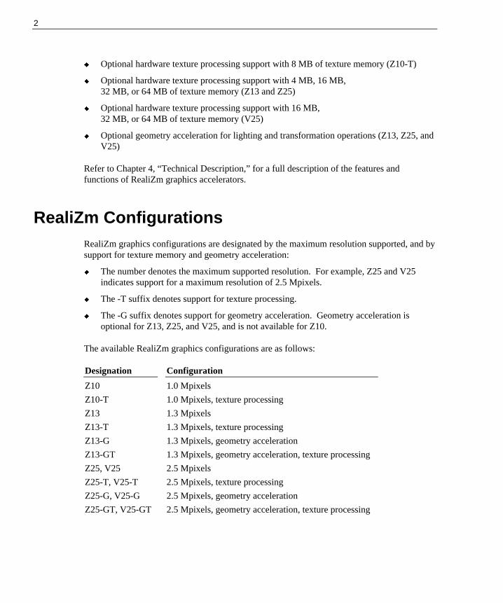
RealiZm Configurations RealiZm graphics configurations are designated by the maximum resolution supported, and bysupport for texture memory and geometry acceleration:
u The number denotes the maximum supported resolution. For example, Z25 and V25indicates support for a maximum resolution of 2.5 Mpixels.
u The -T suffix denotes support for texture processing.
u The -G suffix denotes support for geometry acceleration. Geometry acceleration isoptional for Z13, Z25, and V25, and is not available for Z10.
The available RealiZm graphics configurations are as follows:
Designation Configuration
Z10 1.0 Mpixels
Z10-T 1.0 Mpixels, texture processing
Z13 1.3 Mpixels
Z13-T 1.3 Mpixels, texture processing
Z13-G 1.3 Mpixels, geometry acceleration
Z13-GT 1.3 Mpixels, geometry acceleration, texture processing
Z25, V25 2.5 Mpixels
Z25-T, V25-T 2.5 Mpixels, texture processing
Z25-G, V25-G 2.5 Mpixels, geometry acceleration
Z25-GT, V25-GT 2.5 Mpixels, geometry acceleration, texture processing

3
Starting Windows NT After setting up a system equipped with RealiZm graphics, you can power on the system andstart the Windows NT operating system.
CAUTION Verify that your 3D graphics system is properly set up and ready for use. For Z10, ensure thatthe VGA loopback cable is connected as described in Chapter 2, “Upgrading or ReplacingZ10.”
To start Windows NT:
1. Turn on power to the monitor and to the system base unit.
2. At the boot screen, select the following option:
Windows NT Workstation Version 4.00
3. When prompted, press CTRL+ALT+DEL.
4. Log on to Windows NT. Refer to the Windows NT documentation for instructions, ifnecessary.
RenderGL Run-Time Library Intergraph’s RenderGL run-time library is delivered with your TDZ workstation. This libraryis delivered as a Dynamic Link Library (DLL) file. If you run an application that requires oruses the RenderGL run-time library, you need to install the RenderGL DLL to your system.
The RenderGL DLL is delivered as follows:
u Your system may have been delivered with a diskette containing the RenderGL DLL. Ifso, refer to the README.TXT file on the diskette for installation instructions.
u If your system was not delivered with a diskette containing the RenderGL DLL, you canuse the InterSite Version Manager to create the diskette. Run Version Manager from theWelcome dialog that displays after you set up your TDZ workstation. After you createthe diskette, refer to the README.TXT file on the diskette for installation instructions.
For more information on the RenderGL run-time library, contact Intergraph’s Digital MediaDivision. For more information on the Welcome dialog and Version Manager, refer to yoursystem’s hardware documentation and to Version Manager Help.
4
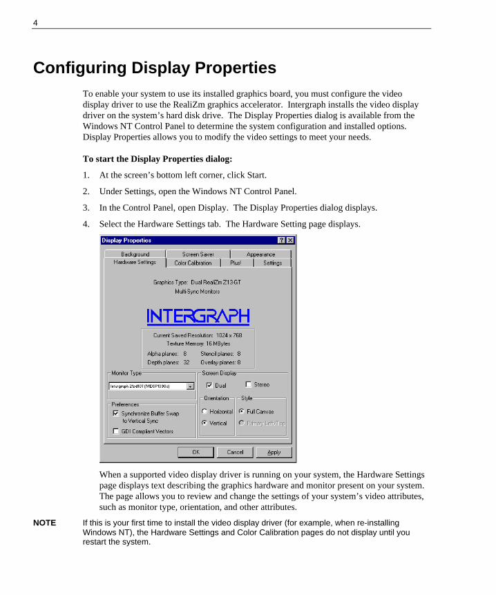
Configuring Display Properties To enable your system to use its installed graphics board, you must configure the videodisplay driver to use the RealiZm graphics accelerator. Intergraph installs the video displaydriver on the system’s hard disk drive. The Display Properties dialog is available from theWindows NT Control Panel to determine the system configuration and installed options.Display Properties allows you to modify the video settings to meet your needs.
To start the Display Properties dialog:
1. At the screen’s bottom left corner, click Start.
2. Under Settings, open the Windows NT Control Panel.
3. In the Control Panel, open Display. The Display Properties dialog displays.
4. Select the Hardware Settings tab. The Hardware Setting page displays.
When a supported video display driver is running on your system, the Hardware Settingspage displays text describing the graphics hardware and monitor present on your system.The page allows you to review and change the settings of your system’s video attributes,such as monitor type, orientation, and other attributes.
NOTE If this is your first time to install the video display driver (for example, when re-installingWindows NT), the Hardware Settings and Color Calibration pages do not display until yourestart the system.

5
5. Select and change the supported settings as desired. Refer to Help for information abouteach setting. Context-sensitive help is available by selecting a setting and pressing F1.
6. Select the Color Calibration tab to change the gamma correction for your monitor, ifdesired. The Color Calibration page displays.
NOTE The Color Calibration page is available only when the driver is running.
The appearance of the Color Calibration page varys, depending on your graphicshardware and selected video display settings. If your system is configured with dualscreens, for example, the page displays two monitor icons to indicate a dual-screendesktop. It can also indicate the dual screens in horizontal orientation or verticalorientation (monitors stacked one on top of the other).
7. Select OK to apply the selected video attributes and to close the Display Propertiesdialog, or select Cancel to close Display Properties without applying the video attributes.
8. If you have changed video attribute settings other than gamma correction, restart thesystem for the changes to take effect.

6
Changing the Default Video Display DriverOnce you have configured the video display as desired, change the default display driver sothat the video display driver runs automatically when you start the system.
To change the default video display driver:
1. Open System in the Windows NT Control Panel. The System dialog displays.
2. Under Operating System, select Windows NT Workstation Version 4.00 fromthe displayed list.
NOTE Do not select the “VGA mode” version of the operating system. The system operates in VGAmode when the video display driver is not running to accommodate all monitor types.
3. Select OK; then close Control Panel. The system will now use the video display driver bydefault.

7
2 Upgrading or Replacing Z10
This chapter describes upgrading or replacing a RealiZm Z10 graphics accelerator in a TDZworkstation. It provides instructions for the following:
u Installing an optional Texturing Accelerator on Z10
u Replacing Z10 or Z10-T
u Installing a Z10 or Z10-T dual-screen upgrade
u Connecting the video cables
u Installing the video display driver
u Troubleshooting the installation
Refer to your system’s hardware documentation for detailed information on opening andclosing the system, avoiding electrostatic discharge, and installing and replacing optionboards.
If an item is missing or damaged, notify the Intergraph Customer Response Center at1-800-633-7248 immediately.
Precautions Static electricity can damage the components inside the system base unit, and can damage thegraphics accelerator boards. To minimize the possibility of electrostatic discharge, do thefollowing:
u Do not remove a graphics accelerator board from its antistatic bag until you are ready toinstall it.
u Handle a graphics accelerator board as little as possible and by the edges only. Do notdrop a graphics accelerator board, and do not expose it to extremes of temperature ormoisture.
u Use an antistatic wrist strap when handling a graphics accelerator board. There is noincreased risk of electrical shock when using the wrist strap. If the wrist strap does notsnugly contact bare skin, static protection will not be effective.

8
To use an antistatic wrist strap:
1. Remove the antistatic wrist strap from its envelope. Unfold the wrist strap and wrap theexposed adhesive side firmly around your bare wrist.
2. Peel the liner from the wrist strap copper foil; then attach the adhesive side of the copperfoil to a bare metal surface (electrical ground) inside the system base unit.
Installing a Texturing Accelerator This section describes installing an optional texturing accelerator on a Z10 board. Adding atexturing accelerator creates a Z10-T graphics accelerator with 8 MB of texture memory.
NOTE You must remove the Z10 board from the system to install a texturing accelerator.
To install a texturing accelerator to a Z10 board:
1. Shut down the system and turn off system power.
2. Disconnect the cables from the Video and VGA ports on the back of the system base unit.
3. Open the system base unit as required to gain access to the PCI option board slots. Slotsare identified in “Connecting the Video Cables” later in this chapter.
4. Use a quarter-inch nutdriver to remove the screws that secure the Z10 board to the systemchassis. Retain the screws.
5. Remove the Z10 board from the system.
NOTE The new Z10-T board set requires two adjacent PCI slots.
6. Use a quarter-inch nutdriver to remove the blanking plates from the following PCI slots:
Z10 board, desktop system: PCI slot 3
Z10 board, deskside system: PCI slot 4
Retain the screws.
7. Remove the texturing accelerator from the antistatic bag.
8. Using a Philips screwdriver, remove the two screws from the Texturing Accelerator I/Opanel shown in the following figure.
9. Align the texturing accelerator with the Z10 board. Insert the two captive screws of thetexturing accelerator with the standoffs on the Z10 board and tighten the screws. Refer tothe following figure.
CAUTION When tightening the captive screws, alternate between the screws using two turns each.

9
10. Insert the two screws previously removed to secure the two I/O panels together.
11. Install the new Z10-T board set in the open PCI slot and in the slot from which youremoved the previously installed Z10 board.
12. Install the screws that were previously removed to secure the Z10-T board set to thesystem chassis.
13. Close the system base unit.
14. Go to “Connecting the Video Cables” later in this chapter to connect the monitor andVGA loopback cables.
15. Restart the system and log on to the Windows NT operating system.
16. Open Display in the Windows NT Control Panel. The Hardware Settings page of theDisplay Properties dialog should display GLZ1-T or Z10-T next to Graphics Type. Ifnot, shut down and power off the system. Ensure that the texturing accelerator is properlyconnected to the Z10 board.
TexturingAcceleratorBoard
Texturing AcceleratorI/O Panel
Captive Screws(alternate tightening)
Z10 Board
Remove these two screwsfrom the Texturing AcceleratorI/O Panel before assembly.
10
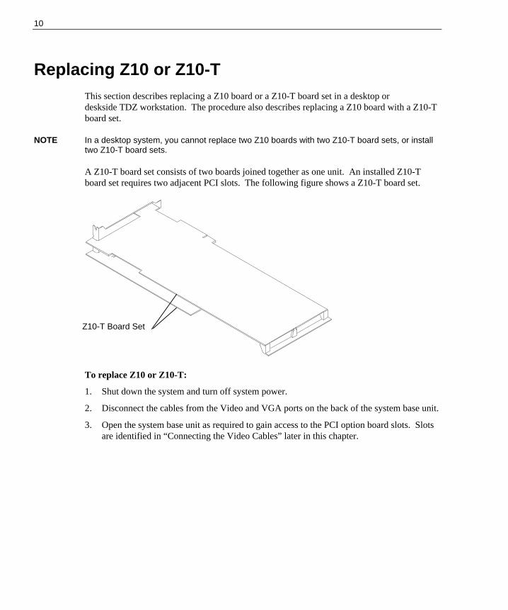
Replacing Z10 or Z10-TThis section describes replacing a Z10 board or a Z10-T board set in a desktop ordeskside TDZ workstation. The procedure also describes replacing a Z10 board with a Z10-Tboard set.
NOTE In a desktop system, you cannot replace two Z10 boards with two Z10-T board sets, or installtwo Z10-T board sets.
A Z10-T board set consists of two boards joined together as one unit. An installed Z10-Tboard set requires two adjacent PCI slots. The following figure shows a Z10-T board set.
To replace Z10 or Z10-T:
1. Shut down the system and turn off system power.
2. Disconnect the cables from the Video and VGA ports on the back of the system base unit.
3. Open the system base unit as required to gain access to the PCI option board slots. Slotsare identified in “Connecting the Video Cables” later in this chapter.
Z10-T Board Set

11
4. If replacing Z10 in a dual-screen configuration, remove the clock sync cable frombetween the Z10 boards or the Z10-T board sets. Refer to the following figures.
5. Use a quarter-inch nutdriver to remove the screws that secure the Z10 board or Z10-Tboard set to the system chassis. Retain the screws.
6. Remove the Z10 board or Z10-T board set from the system.
7. If replacing a single Z10 board with a Z10-T board set in a desktop system, use a quarter-inch nutdriver to remove the blanking plate from PCI slot 3. Retain the screw.
If replacing two Z10 boards with Z10-T board sets in a deskside system, use a quarter-inch nutdriver to remove the blanking plates from PCI slots 4 and 5. Retain the screws.
Z10 Boards
Clock SyncCable
Clock SyncCable
PrimaryZ10-TBoard Set
SecondaryZ10-TBoard Set
12
8. Install the new Z10 board or Z10-T board set in the slots from which you removed thepreviously installed Z10 board or Z10-T board set.
If replacing a single Z10 board with a Z10-T board set, install the new Z10-T board set inPCI slots 2 and 3.
If replacing two Z10 boards with Z10-T board sets in a deskside system, install one newZ10-T board set in PCI slots 2 and 3, and the other in PCI slots 4 and 5.
9. If replacing Z10 in a dual-screen configuration, install the clock sync cable between theZ10 boards or Z10-T board sets. Refer to the figures in step 4.
CAUTION The clock sync cable installs only one way. Do not force the keyed connector. Ensure pin 1of both cable connectors engages pin 1 on both board connectors. The black wire connectsto pin 1.
10. Install the screws that were previously removed to secure the Z10 board or Z10-T boardset to the system chassis.
11. Close the system base unit.
12. Go to “Connecting the Video Cables” later in this chapter to connect the monitor andVGA loopback cables.
Installing a Dual-Screen Upgrade A dual-screen upgrade provides components to upgrade a TDZ workstation from a single-screen configuration to a dual-screen configuration. Verify that you have the following items.
u Z10 board or Z10-T board set
u Diskette containing Intergraph video display driver software
u Clock sync cable
u Antistatic wrist strap
NOTE You cannot install a Z10-T dual-screen upgrade in a desktop system.
If an item is missing or damaged, notify the Intergraph Customer Response Center at1-800-633-7248 immediately.
13
To install a dual-screen upgrade:
1. Shut down the system and turn off system power.
2. Disconnect the cables from the Video and VGA ports on the back of the system base unit.
3. Open the system base unit as required to gain access to the PCI option board slots. Slotsare identified in “Connecting the Video Cables” later in this chapter.
4. Use a quarter-inch nutdriver to remove the blanking plates from the following PCI slots:
Z10 board, desktop system: PCI slot 2
Z10 board, deskside system: PCI slot 3
Z10-T board set, deskside system: PCI slots 4 and 5
Retain the screws.
5. Install the new Z10 board or Z10-T board set in the PCI slots opened in the previous step.
In a dual-screen configuration, the primary and secondary graphics accelerators aredetermined as follows:
Z10 boards, desktop system: Primary in slot 1; secondary in slot 2
Z10 boards, deskside system: Primary in slot 2, secondary in slot 3
Z10-T board sets, deskside system: Primary in slots 2 and 3; secondary in slots 4and 5
6. Install the screws that were previously removed to secure the Z10 board or Z10-T boardset to the system chassis.
7. Install the clock sync cable between the Z10 boards or Z10-T board sets, as shown in thefollowing figures.

14
CAUTION The clock sync cable installs only one way. Do not force the keyed connector. Ensure pin 1of both cable connectors engages pin 1 on both board connectors. The black wire connectsto pin 1.
8. Close the system base unit.
9. Go to “Connecting the Video Cables” later in this chapter to connect the monitor andVGA loopback cables.
10. Restart the system and log on to the Windows NT operating system.
11. Use Display in the Windows NT Control Panel to configure the video display driver torecognize dual screens. Refer to Chapter 1 for more information.
Z10 Boards
Clock SyncCable
Clock SyncCable
PrimaryZ10-TBoard Set
SecondaryZ10-TBoard Set

15
Connecting the Video CablesAfter replacing Z10 or Z10-T or installing a dual-screen upgrade in a TDZ workstation, usethe following instructions to connect the monitor cables and VGA loopback cables asrequired.
CAUTION Do not connect a monitor cable to the VGA loopback cable ports. If you do, the system willboot to a blue screen and stop, or the video will not display.
Single-screen Z10 or Z10-T in a desktop system: Connect the monitor cable to the Videoport, and connect the VGA loopback cable as shown in the following figure.
Dual-screen Z10 in a desktop system: Connect the monitor cables from the primary monitorand the secondary monitor to the Video ports shown in the following figure. Connect theVGA loopback cable as shown in the following figure.
Video Port PCI Slot 2
VGA Loopback Cable
VGA Loopback Cable
Video Port PCI Slot 2(Secondary)
Video Port PCI Slot 1(Primary)
VGA Port (Primary)

16
Single-screen Z10 or Z10-T in a deskside system: Connect the monitor cable to the Videoport, and connect the VGA loopback cable as shown in the following figure.
Dual-screen Z10 in a deskside system: Connect the monitor cables from the primarymonitor and the secondary monitor to the Video ports shown in the following figure. Connectthe VGA loopback cable as shown in the following figure.
VGALoopbackCable
Video Port PCI Slot 2
VGA Port
VGALoopbackCable
Video Port PCI Slot 2(Primary)
Video Port PCI Slot 3(Secondary)
VGA Port (Primary)

17
Dual-screen Z10-T in a deskside system: Connect the monitor cables from the primarymonitor and the secondary monitor to the Video ports shown in the following figure. Connectthe VGA loopback cable as shown in the following figure.
Installing the Video Display Driver As an aid to troubleshooting, or should it become necessary to re-install the video displaydriver, this section describes installing the Intergraph video display driver for Z10 or Z10-T.The system must be running Windows NT to install the video display driver.
NOTE The video display driver for Z10 and Z10-T is different from the video display driver for Z13and Z25.
To install the video display driver:
1. Turn on system power and log on to the Windows NT operating system.
2. Open Display in the Windows NT Control Panel. The Display Properties dialog displays.
3. Select the Settings tab. The Settings page displays.
4. Select Display Type. The Display Type dialog displays.
5. Select Change. The Change Display dialog displays.
6. Select Have Disk.
7. Insert the diskette containing the Intergraph video display driver into the floppy diskdrive; then, select OK.
8. At Change Display, select OK.
9. At the third-party driver warning, select YES.
10. At the Installing Driver dialog, select OK.
VGALoopbackCable
Video Port PCI Slot 2(Primary)
Video Port PCI Slot 4(Secondary)
VGA Port (Primary)

18
11. At the Display Type dialog, select Close.
12. If desired, configure the video display according to the system configuration and yourpreferences. Refer to your system documentation, or select a setting and press F1, formore information.
13. Select Apply at the bottom of the dialog to apply the attributes.
14. Remove the diskette from the floppy disk drive.
15. Restart the system.
TroubleshootingThis section contains troubleshooting procedures to help determine which hardware assemblyto return for repair, if you suspect a hardware problem. If problems persist, contact theIntergraph Customer Response Center at 1-800-633-7248.
Diagnostics
Diagnostic utilities for checking the graphics boards and instructions for using them areavailable on the Intergraph Bulletin Board Service (IBBS). Refer to the front of this guide forinstructions to access the IBBS and obtain files.
Video Display
The following table lists some common video configuration problems.
Problem Action
Display is black, not synchronized,or distorted.
Restart Windows NT in VGA mode.
Monitor does not support aselected resolution or refresh rate.
Select a supported resolution and refresh rate.
Two Z10 boards or two Z10-Tboard sets installed, but you cannotselect the Dual Screen option.
Verify proper installation of both Z10 boards orZ10-T board sets (only one board or board setwas detected).
A dim line, rolling vertically, isvisible on the screen.
Verify proper installation of the clock sync cable.

19
Problem Action
No VGA bootup screen. Check the VGA loopback cable. Disconnect themonitor cable from the Video port and connect itto the VGA port. If no display, check the systemboard, monitor, monitor cable, and power to themonitor.
Obtaining a Usable Video Resolution
The system operates in VGA mode when the Intergraph video display driver is not running toaccommodate all monitor types. VGA mode is used during initial installation of the videodisplay driver and when experiencing video problems.
If you select a resolution that causes the monitor to display incorrectly, do not pressCTRL+ALT+DEL to log on to the Windows NT operating system. Instead, use the Last KnownGood option to return to the last known good configuration recorded by Windows NT.
To use the Last Known Good option:
1. Restart the system.
2. Press the space bar at the following prompt:
Press space bar NOW to invoke the Last Known Good Menu
If using the Last Known Good option fails to correct the video display problems, you canobtain a functional video resolution by restarting the system in VGA mode.
To restart the system in VGA mode:
1. Restart the system.
2. At the boot screen, select the following option:
Windows NT Workstation Version 4.00 [VGA mode]
Determining a Defective Unit
To determine a defective unit:
1. Save and exit from all files, if possible.
2. Shut down Windows NT, if possible.
3. Turn off the power to the monitor and to the system base unit.
CAUTION Always turn off the power to the workstation before connecting or disconnecting the cables.
4. Check and reseat all board and cable connections as needed.

20
5. Turn on the power to the monitor. If the Power On LED does not illuminate, return themonitor.
NOTE After a period of inactivity, the monitor enters a power saving mode. On Intergraph Multi-syncmonitors, the Power On LED on the front of the monitor will change from green to yellow toindicate the power saving mode is active.
6. Turn on the power to the system base unit. If the Power On LED on the base unit doesnot illuminate or if the BIOS beep codes indicate a failure, return the workstation.
7. If the monitor display is distorted, ensure the software setup is correct for the monitortype.
If the software setup is correct, use a similar type monitor (if available and functioningproperly) to determine if the workstation is defective.

21
3 Upgrading or Replacing Z13, Z25, and V25
This chapter describes installing or replacing a RealiZm Z13, Z25, or V25 graphicsaccelerator in a TDZ workstation. It provides instructions for the following:
u Installing optional texture memory on Z13, Z25, and V25
u Replacing Z13, Z25, or V25, or installing an optional Geometry Accelerator
u Installing a Z13, Z25, or V25 dual-screen upgrade
u Connecting the video cables
u Installing the video display driver
u Troubleshooting the installation
Refer to your system’s hardware documentation for detailed information on opening andclosing the system, avoiding electrostatic discharge, and installing and replacing optionboards.
If an item is missing or damaged, notify the Intergraph Customer Response Center at1-800-633-7248 immediately.
Precautions Static electricity can damage the components inside the system base unit, and can damagetexture memory or graphics accelerator boards. To minimize the possibility of electrostaticdischarge, do the following:
u Do not remove texture memory or a graphics accelerator board from its antistatic baguntil you are ready to install it.
u Handle texture memory or a graphics accelerator board as little as possible and by theedges only. Do not drop texture memory or a graphics accelerator board, and do notexpose either to extremes of temperature or moisture.
u Use an antistatic foam pad to support a graphics accelerator board when installing texturememory.
u Use an antistatic wrist strap when handling texture memory or a graphics acceleratorboard. There is no increased risk of electrical shock when using the wrist strap. If thewrist strap does not snugly contact bare skin, static protection will not be effective.

22
To use an antistatic wrist strap:
1. Remove the antistatic wrist strap from its envelope. Unfold the wrist strap and wrap theexposed adhesive side firmly around your bare wrist.
2. Peel the liner from the wrist strap copper foil; then attach the adhesive side of the copperfoil to a bare metal surface (electrical ground) inside the system base unit.
Installing Texture Memory This section describes installing texture memory on a Z13, Z25, or V25 board. The texturememory system on a Z13, Z25, or V25 board contains two sockets for dual inline memorymodules (DIMMs).
Intergraph upgrade kits are available for 4 MB, 16 MB, 32 MB, and 64 MB of texturememory. Each kit contains two DIMMs, an antistatic foam pad to support the graphicsaccelerator board, and an antistatic wrist strap. Texture memory for V25 ranges in size from16 MB to 64 MB.
NOTE You must remove the Z13, Z25, or V25 board from the system to install texture memory.
The following figure shows the location of the texture memory sockets on a Z13 board.
The following figure shows the location of the texture memory sockets on a Z25 or V25board. You must remove the DIMM access cover to install texture memory.
TextureMemorySockets

23
NOTE For proper operation, you must install DIMMs of the same memory size, and you must fill bothsockets.
To install texture memory:
1. Remove the Z13, Z25, or V25 board from the system. Refer to “Replacing Z13, Z25,V25, or Geometry Accelerator” later in this chapter for instructions.
2. Place the board on the antistatic foam pad for protection and support.
CAUTION Failure to use the antistatic foam pad could cause damage to the board.
3. For a Z25 or V25 board, remove the DIMM access cover.
4. Remove a DIMM from its static protective bag.
CAUTION Do not bend, twist or drop DIMMs. They may be damaged as a result.
5. Align the DIMM notches with the keys in one of the texture memory sockets on theboard, and insert the DIMM into the socket. Refer to the following figure.
TextureMemorySockets
DIMMAccessCover

24
6. Push on the top edge of the DIMM until it snaps into the socket. Refer to the followingfigure.
7. Repeat steps 4 through 6 for the second DIMM.
8. For a Z25 or V25 board, replace the DIMM access cover.
9. Replace the board into the system.
10. Close the system base unit.
11. Turn on system power and log on to the Windows NT operating system.
12. Open Display in the Windows NT Control Panel. The Hardware Settings page of theDisplay Properties dialog should display the proper texture memory size. If not, shutdown and power off the system. Ensure that both DIMMs are properly seated in theirsockets, and that both DIMMs are the same memory size.
Replacing Z13, Z25, V25, or Geometry AcceleratorThis section describes replacing a Z13, Z25, V25, or optional Geometry Accelerator board ina desktop or deskside TDZ workstation. The procedure also describes installing a newGeometry Accelerator board.
An installed Z13, Z25, or V25 board requires two adjacent PCI slots. An installed GeometryAccelerator board requires one PCI slot.
To replace a Z13, Z25, V25, or Geometry Accelerator board:
1. Shut down the system and turn off system power.
2. If replacing a Z13, Z25, or V25 board, disconnect the cables from the Video ports on theback of the system base unit.
DIMM
25
3. Open the system base unit as required to gain access to the PCI option board slots. Slotsare identified in “Connecting the Video Cables” later in this chapter.
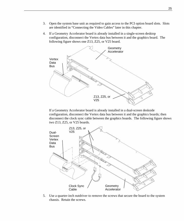
4. If a Geometry Accelerator board is already installed in a single-screen desktopconfiguration, disconnect the Vertex data bus between it and the graphics board. Thefollowing figure shows one Z13, Z25, or V25 board.
If a Geometry Accelerator board is already installed in a dual-screen desksideconfiguration, disconnect the Vertex data bus between it and the graphics boards; thendisconnect the clock sync cable between the graphics boards. The following figure showstwo Z13, Z25, or V25 boards.
5. Use a quarter-inch nutdriver to remove the screws that secure the board to the systemchassis. Retain the screws.
Clock SyncCable
GeometryAccelerator
Dual-ScreenVertexDataBus
VertexDataBus
Z13, Z25, orV25
Z13, Z25, orV25
GeometryAccelerator

26
If installing a new Geometry Accelerator board, use a quarter-inch nutdriver to removethe blanking plate from the following slot:
Desktop system: PCI slot 1
Deskside system: PCI slot 5
Retain the screw.
6. Remove the installed board from the system.
7. Install the new Z13, Z25, V25, or Geometry Accelerator board in the slots from whichyou removed the previously installed boards.
If installing a new Geometry Accelerator board, install the board in the PCI slot opened instep 5.
8. Install the screws that were previously removed to secure the Z13, Z25, V25, orGeometry Accelerator board to the system chassis.
9. If a Geometry Accelerator board is installed, connect the Vertex data bus between it andthe graphics board(s). Refer to the figures in step 4.
NOTE The connector of the Vertex data bus can be installed in only one orientation.
10. If replacing Z13, Z25, or V25 in a dual-screen deskside configuration, connect the clocksync cable between the graphics boards. Refer to the figures in step 4.
CAUTION The clock sync cable installs only one way. Do not force the keyed connector. Ensure pin 1of both cable connectors engages pin 1 on both board connectors. The black wire connectsto pin 4.
11. Close the system base unit.
12. Go to “Connecting the Video Cables” later in this chapter to connect the monitor cables.
Installing a Dual-Screen UpgradeA dual-screen upgrade provides components to upgrade a TDZ deskside workstation from asingle-screen configuration to a dual-screen configuration. Verify that you have the followingitems.
u Z13, Z25, or V25 board
u Vertex data bus for dual-screen configuration (used only if optional GeometryAccelerator is installed)
u Clock sync cable
u Antistatic wrist strap
NOTE You cannot install a dual-screen upgrade in a desktop system.

27
If an item is missing or damaged, notify the Intergraph Customer Response Center at1-800-633-7248 immediately.
To install a dual-screen upgrade:
1. Shut down the system and turn off system power.
2. Disconnect the cable from the Video port on the back of the system base unit.
3. Open the system base unit as required to gain access to the PCI option board slots. Slotsare identified in “Connecting the Video Cables” later in this chapter.
4. Use a quarter-inch nutdriver to remove the blanking plates from PCI slots 1 and 2. Retainthe screws.
5. Install the new Z13, Z25, or V25 board in PCI slots 1 and 2.
In a dual-screen configuration, the primary and secondary Z13, Z25, and V25 graphicsaccelerators are determined as follows:
Primary: Board installed in PCI slots 1 and 2
Secondary: Board installed in PCI slots 3 and 4
6. Install the screws that were previously removed to secure the board to the system chassis.
7. If a Geometry Accelerator board is installed, connect the dual-screen Vertex data busbetween it and the graphics boards. The following figure shows two Z13, Z25, or V25boards.
NOTE The connectors of the dual-screen Vertex data bus can be installed in only one orientation.
8. Install the clock sync cable between the two Z13, Z25, or V25 boards shown in theprevious figure.
Clock SyncCable
Dual-ScreenVertexDataBus
Z13, Z25, orV25
GeometryAccelerator

28
CAUTION The clock sync cable installs only one way. Do not force the keyed connector. Ensure pin 1of both cable connectors engages pin 1 on both board connectors. The black wire connectsto pin 4.
9. Close the system base unit.
10. Go to “Connecting the Video Cables” in this chapter to connect the monitor cables.
11. Restart the system and log on to the Windows NT operating system.
12. Use Display in the Windows NT Control Panel to configure the video display driver torecognize dual screens. Refer to Chapter 1 for more information.
Connecting the Video CablesAfter replacing Z13, Z25, or V25, or installing a dual-screen upgrade in a TDZ workstation,use the following instructions to connect the monitor cables as required.
CAUTION Do not connect the monitor cables to the VGA ports. If you do, the video will not display.
Z13, Z25, or V25 in a desktop system: Connect the monitor cable to the Video port shownin the following figure.
Video Port PCI Slot 2
VGA Port (not used)

29
Single-screen Z13, Z25, or V25 in a deskside system: Connect the monitor cable to theVideo port shown in the following figure.
Dual-screen Z13, Z25, or V25 in a deskside system: Connect the monitor cables from theprimary monitor and the secondary monitor to the Video ports shown in the following figure.
Video Port PCI Slot 3
VGA Port (not used)
Video Port PCI Slot 1(Primary)
Video Port PCI Slot 3(Secondary)
VGA Ports (not used)
30
Installing the Video Display Driver As an aid to troubleshooting, or should it become necessary to re-install the video displaydriver, this section describes installing the Intergraph video display driver for Z13, Z25, andV25. The system must be running Windows NT to install the video display driver.
NOTE The video display driver for Z13, Z25, and V25 is different from the vide o display driver forZ10.
To install the video display driver:
1. Turn on system power and log on to the Windows NT operating system.
2. Open Display in the Windows NT Control Panel. The Display Properties dialog displays.
3. Select Settings. The Settings page displays.
4. Select Display Type. The Display Type dialog displays.
5. Select Change. The Change Display dialog displays.
6. Select Have Disk.
7. Insert the diskette containing the Intergraph video display driver into the floppy diskdrive; then, select OK.
8. At Change Display, select OK.
9. At the third-party driver warning, select YES.
10. At the Installing Driver dialog, select OK.
11. At the Display Type dialog, select Close.
12. If desired, configure the video display according to the system configuration and yourpreferences. Refer to your system documentation, or select a setting and press F1, formore information.
13. Select Apply at the bottom of the dialog to apply the attributes.
14. Remove the diskette from the floppy disk drive.
15. Restart the system.

31
TroubleshootingThis section contains troubleshooting procedures to help determine which hardware assemblyto return for repair, if you suspect a hardware problem. If problems persist, contact theIntergraph Customer Response Center at 1-800-633-7248.
Diagnostics
Diagnostic utilities for checking the graphics boards and instructions for using them areavailable on the Intergraph Bulletin Board Service (IBBS). Refer to the front of this guide forinstructions to access the IBBS and obtain files.
Video Display
The following table lists some common video configuration problems.
Problem Action
Display is black, not synchronized,or distorted.
Restart Windows NT in VGA mode.
Monitor does not support aselected resolution or refresh rate.
Select a supported resolution and refresh rate.
Two graphics boards installed, butyou cannot select the Dual Screenoption.
Verify proper installation of all RealiZm graphicsboards (only one board was detected).
A dim line, rolling vertically, isvisible on the screen.
Verify proper installation of the clock sync cable.
Obtaining a Usable Video Resolution
The system operates in VGA mode when the Intergraph video display driver is not running toaccommodate all monitor types. VGA mode is used during initial installation of the videodisplay driver and when experiencing video problems.
If you select a resolution that causes the monitor to display incorrectly, do not pressCTRL+ALT+DEL to log on to the Windows NT operating system. Instead, use the Last KnownGood option to return to the last known good configuration recorded by Windows NT.
To use the Last Known Good option:
1. Restart the system.
2. Press the space bar at the following prompt:
32
Press space bar NOW to invoke the Last Known Good Menu
If using the Last Known Good option fails to correct the video display problems, you canobtain a functional video resolution by restarting the system in VGA mode.
To restart the system in VGA mode:
1. Restart the system.
2. At the boot screen, select the following option:
Windows NT Workstation Version 4.00 [VGA mode]
Determining a Defective Unit
To determine a defective unit:
1. Save and exit from all files, if possible.
2. Shut down Windows NT, if possible.
3. Turn off the power to the monitor and to the system base unit.
CAUTION Always turn off the power to the workstation before connecting or disconnecting the cables.
4. Check and reseat all board and cable connections as needed.
5. Turn on the power to the monitor. If the Power On LED does not illuminate, return themonitor.
NOTE After a period of inactivity, the monitor enters a power saving mode. On Intergraph Multi-syncmonitors, the Power On LED on the front of the monitor will change from green to yellow toindicate the power saving mode is active.
6. Turn on the power to the system base unit. If the Power On LED on the base unit doesnot illuminate or if the BIOS beep codes indicate a failure, return the workstation.
7. If the monitor display is distorted, ensure the software setup is correct for the monitortype.
If the software setup is correct, use a similar type monitor (if available and functioningproperly) to determine if the workstation is defective.
33
4 Technical Description
This chapter provides a technical description of the RealiZm graphics accelerators and theoptional Geometry Accelerator.
Rasterization Accelerator Features RealiZm graphics accelerators include advanced features to accelerate the rasterization ofcomputer graphics and enhance visual impact. The integrated Z10, Z13, Z25, and V25rasterization accelerators comprise a Peripheral Component Interconnect (PCI) Bus Interface,Graphics Engine, Texture Processor, and Frame Buffer.
The PCI Bus Interface features:
u PCI compatible bus interface
u High-speed direct memory access (DMA) engine
u Interface for Geometry Accelerator (Z13, Z25, and V25)
The Graphics Engine features:
u High-level vertex interface
u Gouraud shading support
u Symbolized vector support
u Antialiased vector support
u Sub-pixel accuracy
u Window clipping (Z13, Z25, and V25)
The Texture Processor features:
u Advanced texture processor hardware
u Texture memory
u MIP-mapping support with trilinear interpolation

34
The Frame Buffer features:
u Video planes
u True-color image buffer
u High-resolution Z buffer
u Stencil buffer (Z13, Z25, and V25)
u Alpha buffer (Z13, Z25, and V25)
u Multiple video lookup tables
u Window-mode double buffering
u Gamma correction
u Hardware cursor
u Stereoscopic viewing
u Multiple video resolutions
u High-speed screen refresh
u Genlock support for dual monitors
PCI Bus Interface
The Z10, Z13, Z25, and V25 graphics accelerators are 32-bit PCI peripherals.
PCI-Compatible Bus Interface
The PCI direct memory access (PCIDMA) application-specific integrated circuit (ASIC)provides the PCI-compatible bus interface for these accelerators, including bus mastershipcapability. This interface provides a high-speed, industry-standard connection between thehost processor and the graphics accelerator.
High-Speed DMA Engine
The Rasterization Accelerator uses a high-speed DMA engine to accelerate PCI bus datatransfers. The DMA engine transfers data in bursts without intervention from the hostprocessor. These unattended transfers free the host processor from transferring massiveamounts of graphics data over the PCI bus.

35
Interface for Geometry Accelerator (Z13, Z25, and V25)
Geometry calculations, such as lighting and perspective adjustment, are performed either bythe host processor or by an optional Geometry Accelerator. If installed, the GeometryAccelerator sends vertex data to the Rasterization Accelerator via a dedicated connector. Adirect connection allows data to flow quickly to the Rasterization Accelerator, which enhancesperformance.
Graphics Engine
The Graphics Engine is the core of the Rasterization Accelerator. It accelerates the translationof high-level graphics requests into pixel-oriented requests through derivative calculations andspan iteration. It then coordinates the movement of pixels to the Frame Buffer.
High-Level Vertex Interface
The Rasterization Accelerator allows the software to send vertex data for triangles and vectorsin multiple formats. Supported formats include 8-bit packed integer, 16-bit packed integer,32-bit integer, single-precision floating point, and double-precision floating point.
The host processor achieves higher performance because it does not convert data that is nativeto a particular application. To conserve bandwidth, the application optionally loads constantcolor and Z values to avoid sending them with each vertex.
Gouraud Shading Support
The Graphics Engine supports smooth shading of 3D triangle meshes with the Gouraudalgorithm. High performance hardware accomplishes the shading of the entire triangle,including color and depth derivative calculations and pixel interpolation. The hardware alsoallows maximum update rates with minimum load on the host processor.
Symbolized Vector Support
The Graphics Engine supports the application of any user-supplied, two-color pattern ontovectors without performance degradation. Dotted or dashed lines are examples of symbolizedvectors.
Antialiased Vector Support
Hardware support of antialiased vectors eliminates the jagged appearance of vectors onstandard raster displays.

36
Sub-Pixel Accuracy
The Graphics Engine uses sub-pixel accuracy for improving the quality of the graphics image.Sub-pixel accuracy ensures adjacent polygons and vectors join smoothly.
Window Clipping (Z13, Z25, and V25)
While rendering triangles and vectors, the Graphics Engine discards pixels that would falloutside the region of the target window. Hardware clipping in this fashion alleviates theburden of checking objects in software before sending them to the graphics system.
Texture Processor
Texturing is available on RealiZm graphics accelerators that have a texturing accelerator(Z10) or texture memory (Z13, Z25, and V25) installed. Texturing is the process of applyinga pattern, represented in memory as a two-dimensional array of image color values, to thesurface of a 3D graphical object. For example, a wood grain pattern can be texture-mapped tothe surface of an object, such as a desk, to enhance realism of the image.
Another example of texture mapping is draping a land image from a satellite over a digitalterrain model to create a 3D representation. The Texture Processor module of the RealiZmgraphics accelerators provides a dramatic performance increase for advanced textureprocessing when compared with software algorithms alone.
Advanced Texture Processor Hardware
The Texture Processor has its own ASICs on the Z10, and is integrated into the GraphicsEngine/Texture Processor ASIC on the Z13, Z25, and the V25. It supports 32-bit textures,one byte for each of the color components: red, green, blue, and alpha.
Texture Memory
Texture memory is 8 MB in a Z10 with the hardware texture option, providing up to 2MTexels of texture maps. If installed in a Z13 or Z25, texture memory ranges in size from 4MB to 64 MB, providing from 1 MTexels to 16 MTexels of texture maps. If installed in V25,texture memory ranges in size from 16 MB to 64 MB, providing from 4 MTexels to 16MTexels of texture maps.

37
MIP-Mapping Support with Trilinear Interpolation
The Texture Processor allows various sizes of texture maps to coexist in texture memory.Different MIP (multum in parvo -- many things in a small place) maps allow the appropriatelevel of detail to be shown based on viewing distance. The Texture Processor chooses fourtexels nearest the actual texel value from each of the nearest two MIP maps (for a total ofeight texels). The Texture Processor blends the eight texels to produce the actual texel valueby using trilinear interpolation.
Frame Buffer
The RealiZm Frame Buffers are full-featured: Their deep pixel formats provide a flexibleenvironment for applications with hardware acceleration. For example, double-bufferedoverlay planes provide the ability to annotate text and graphics over a 3D image in the imagebuffer. Both image buffers have access to one of four video lookup tables (VLTs). The imageVLT selection planes select the VLT to use. The mask planes allow for access control of thevarious drawing planes (for example, image or overlay). The image and overlay bufferselection control planes determine the buffer to display on a pixel-by-pixel basis. Otherfeatures include support of a wide variety of displays operating at high resolution.
Video Planes
Z10 supports 84 bits-per-pixel plane sets, and Z10-T supports 90 bits-per-pixel configurations,as summarized in the following table:
Video Plane Sets 84 Bits/Pixel 90 Bits/Pixel
Image (red, green, blue), front buffer 24 24
Image (red, green, blue), back buffer 24 24
Overlay, front buffer 1 4
Overlay, back buffer 1 4
Image, VLT selection, front buffer 3 3
Image, VLT selection, back buffer 3 3
Z buffer 24 24
Mask (pixel access control) 2 2
Image, window control 1 1
Overlay, window control 1 1
Z13, Z25, and V25 support two plane set configurations: 100 bits-per-pixel and 128 bits-per-pixel. The 128 bits-per-pixel mode is supported at resolutions slightly less than the maximum.For example, the Z25 supports 128 bits-per-pixel up to maximum resolution of 2 Mpixel(1600 x 1200) and 100 bits-per-pixel for a resolution of 2.5 Mpixel (1824 x 1368).

38
The following table summarizes the video plane sets for the Z13, Z25, and V25 accelerators.
Video Plane Sets 100 Bits/Pixel 128 Bits/Pixel
Image (red, green, blue), front buffer 24 24
Image (red, green, blue), back buffer 24 24
Overlay, front buffer 4 8
Overlay, back buffer 4 8
Image, VLT selection, front buffer 4 4
Image, VLT selection, back buffer 4 4
Z buffer 24 32
Mask (pixel access control) 2 4
Image, buffer selection control 1 1
Overlay, buffer selection control 1 1
Alpha 0 8
Stencil 6 8
Fast Clear Front Buffer 1 1
Fast Clear Back Buffer 1 1
True-Color Image Buffer
The true-color image buffer is 24 bits and double-buffered. It contains the red, green, andblue components of the image with 8 bits per component to provide 16.7 million colors.There are two copies, or buffers, of image data: a front buffer and a back buffer. Two buffersenhance smooth animation, since applications may update the back buffer while displaying thefront buffer.
High-Resolution Z Buffer
The Z buffer holds 24 bits of depth information (Z10) or up to 32 bits of depth information(Z13, Z25, and V25). Depth represents a distance from the observer’s eye to an object in ascene. A large Z buffer enables representation of a large number of unique depth values,which provides a more accurate rendering of scenes with large depth separation betweenobjects.
Stencil Buffer (Z13, Z25, and V25)
The stencil buffer holds up to 8-bits of stencil information. This buffer is a general-purposeresource for OpenGL applications. In a typical case, stenciling inhibits writes to portions ofan application’s window, but allows writes to other portions. The Frame Buffer acceleratesbuilding the values in the stencil buffer, and also accelerates the action of inhibiting orallowing writes on a per-pixel basis.

39
Alpha Buffer (Z13, Z25, and V25)
The alpha buffer holds up to 8-bits of alpha information. Alpha planes and alpha blendinglogic in the Frame Buffer assist the application in rendering scenes more realistically. Specialeffects that might result from alpha blending include transparency or tinting.
Multiple Video Lookup Tables
The Frame Buffer includes up to four VLTs. The VLTs provide multiple color palettessimultaneously for color remapping and advanced color refinement.
Window-Mode Double-Buffering
Window-mode double-buffering allows multiple windows to display simultaneously fromdifferent buffers.
Gamma Correction
10-bit gamma VLTs and 10-bit digital-to-analog converters (DACs) allow fine control ofdisplayed colors without color degradation.
Hardware Cursor
Hardware superimposes the cursor image over the video stream in real time, minimizing thecursor management tasks required by the host processor.
Stereoscopic Viewing
RealiZm graphics accelerators support the display of stereo images. Stereoscopic viewingrequires a stereo-ready monitor and infrared shutter glasses with emitter module.
Multiple Video Resolutions
RealiZm graphics accelerators include programmable pixel clock generation and video timinglogic. This allows support of a wide variety of monitors with multiple video resolutions andrefresh rates. Programmable video timing also allows future monitor upgrades with only asoftware driver change. Supported resolutions range from 640 x 480 up to 1152 x 864 (Z10)or 1280 x 1024 (Z13) or 1824 x 1368 (Z25 and V25). Refer to Chapter 6 for additionalinformation on supported monitor resolutions.

40
High-Speed Screen Refresh
High-speed screen refresh provides flicker-free displays up to 76 Hz (Z10) or 85 Hz (Z13,Z25, and V25) for most screen resolutions.
Genlock Support for Dual Monitors
A clock sync cable installed between RealiZm board sets synchronizes the monitors in a dual-monitor configuration. This Genlock method eliminates the visual beat frequency effect thatmay occur when placing two monitors close to each other.
Rasterization Accelerator Functions Graphics Device Interface (GDI) is the library of functions that the Windows NT operatingsystem uses to create and manipulate 2D computer images. RealiZm rasterization hardwareaccelerates many GDI functions.
OpenGL is an industry standard library of functions used to create and manipulate 3Dcomputer images. OpenGL functions, as a part of the Windows NT operating system, can beperformed by the host processor. RealiZm hardware accelerators greatly improve OpenGLperformance.
For the Z13, Z25, and V25 accelerators, either the host processor or an optional GeometryAccelerator performs the geometry stage of the OpenGL processing. While the GeometryAccelerator processes OpenGL requests, the host processor is freed to perform application anddatabase operations. This parallel processing results in unprecedented speed to generate andmanipulate realistic images.
As shown in the following figure, the Rasterization Accelerator includes:
u Pixelization Accelerator
u Texture Processor (optional)
u Frame Buffer

41
UsingOpenGL
Application
RasterizationAccelerator
Geometry Accelerator(Z13, Z25, and V25 Optional)
Geometry Processing
PixelizationAccelerator
Frame Buffer
Monitor
TextureProcessor(Optional)
Pixelization Accelerator
The Pixelization Accelerator consists of PCIDMA, graphics first-in-first-out (FIFO), and theGraphics Engine. The standard PCI bus provides high bandwidth support for the transfer ofgraphics data between the host processor and the Rasterization Accelerator. If the GeometryAccelerator is present (for Z13, Z25, and V25), then the system transfers data from the hostprocessor to the Geometry Accelerator, which then transfers data to the RasterizationAccelerator via a dedicated bus.
The Rasterization Accelerator receives GDI or OpenGL element requests from the hostprocessor (or from the Geometry Accelerator, if present), through the PCIDMA and graphicsFIFO. Element types include triangles, triangle meshes, lines, line strings, and others. TheGraphics Engine ASIC converts the elements to pixels and routes them through the resolversto video memory.
The Rasterization Accelerator also performs region fills, bit expands, and BIT BLock Transfer(BITBLT) operations. Optional processing of the pixels is performed by the TextureProcessor prior to the Graphics Engine sending them to the resolvers.
42
Texture Processor
The Texture Processor resides in dedicated ASICs (Z10) or is physically part of the GraphicsEngine/Texture Processor ASIC (Z13, Z25, and V25). It supports 32-bit textures: 8 bits foreach color component (red, green, blue, and alpha).
The Texture Processor receives two types of setup parameters from the Graphics Engine: onetype for triangles and one type for pixel spans within a triangle. The triangle setup parametersconsist of texturing control information and texture coordinate derivatives. The pixel spansetup parameters consist of initial texture coordinates. These texturing setup parameterscontrol the interpolation of the texture coordinate values. The texture processors correct forperspective during texture coordinate interpolation and thereby reduce image distortion.
The texture memory is capable of storing several sets of MIP-mapped textures for subsequenttexture mapping. In MIP-mapping, software creates smaller-sized versions of a base textureand stores them in texture memory. The smaller versions represent the base texture at varyingdistances from the viewer’s eye.
The Texture Processor chooses eight texels nearest the actual texel value from the nearest twoMIP maps. The Texture Processor interpolates these eight texels to produce the actual texelvalue through the use of trilinear interpolation.
The actual texel value can either replace or blend with the Gouraud shaded pixel valuegenerated by the Graphics Engine. Finally, the Graphics Engine routes the textured pixelsfrom the Texture Processor to the resolvers, which write the textured pixels into videomemory.
Frame Buffer
The Frame Buffer consists of the resolvers, video memory, and a DAC. Z10 resolvers controlthe flow of digital pixel data from the video memory to the video selector and mappers(VSMs) and then to the DAC where it is converted to an analog voltage and presented to themonitor. Refer to the following figure.

43
Resolver
Z10RealiZmRasterizationAccelerators
VideoMemory
6 MB
VideoSelector and
Mapper
PCI Bus
PCIDMA
Graphics FIFO
Slope Calculation
Request Handler
Span Generation
Pixel Interpolation
Graphics Engine
IZ Bus
Resolver
VideoMemory
6 MB
VideoSelector and
Mapper
Digital To Analog Converter
Monitor
Z10 has a total of12 MB Video Memoryand two resolvers
TextureMemory
8 MB(Optional)
Four TextureProcessorsR, G, B, A(Optional)

44
Z13, Z25, and V25 resolvers retrieve digital pixel data from video memory, and send it to theDAC where it is converted to an analog voltage and presented to the monitor.
Z13, Z25, andV25 RealiZmRasterizationAccelerators(Z13 shown)
PCI Bus
PCIDMA
Graphics FIFO
Slope Calculation
Request Handler
Span Generation
Pixel Interpolation
Graphics Engine
IZ Bus
Z13 has a total of16 MB Video Memoryand two dual resolvers.
Both Z25 and V25 havea total of 32 MB VideoMemory and four dualresolvers.
VideoMemory
8MB
DualResolver
VideoMemory
8MB
DualResolver
Digital To Analog Converter
Monitor
TextureMemory
(Optional)
TextureProcessor

45
Geometry Accelerator Features and Functions The Geometry Accelerator available for use with Z13, Z25, and V25 employs the followingfeatures and functions to accelerate the geometry processing requirements of computergraphics.
u High-speed graphics DMA engine
u MIMD DSP architecture
u Sequence Controller
High-Speed Graphics DMA Engine
The Geometry Accelerator uses high-speed DMA engines to accelerate PCI bus data transfers.An independent DMA engine transfers data in bursts and frees the host processor fromtransferring massive amounts of graphics data over the PCI bus.
MIMD DSP Architecture
The Geometry Accelerator features a multiple instruction multiple data (MIMD) architectureto harness the power of six floating-point digital signal processors (DSPs) operating inparallel. The DSPs speed the compute-intensive geometry calculations of 3D graphics. EachDSP can execute 120 million floating point operations per second (MFLOPS), and contains10 DMA engines to ensure nonstop data flow to the Sequence Controller.
Sequence Controller
To achieve maximum efficiency in a MIMD architecture, multiple processors operateindependently on multiple data sets. The six Geometry Accelerator DSPs process graphicsrequests in turn and may generate output requests in a different order than the input requests.The Sequence Controller places the output requests into the proper time sequence.
The PCI bus is a high-performance bus capable of operating up to 33 MHz. The GeometryAccelerator is a 32-bit PCI bus peripheral with bus mastership capability, which uses the PCIbus to transfer data from the host processor.
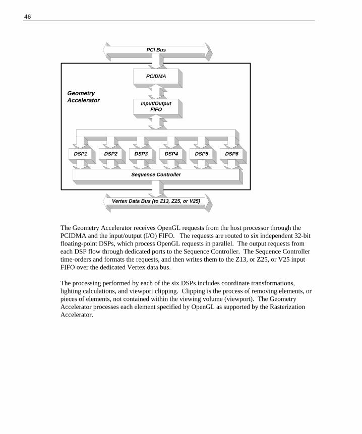
46
GeometryAccelerator
PCI Bus
PCIDMA
Input/OutputFIFO
DSP IO Bus
DSP6DSP5DSP4DSP3DSP2DSP1
Sequence Controller
Vertex Data Bus (to Z13, Z25, or V25)
The Geometry Accelerator receives OpenGL requests from the host processor through thePCIDMA and the input/output (I/O) FIFO. The requests are routed to six independent 32-bitfloating-point DSPs, which process OpenGL requests in parallel. The output requests fromeach DSP flow through dedicated ports to the Sequence Controller. The Sequence Controllertime-orders and formats the requests, and then writes them to the Z13, or Z25, or V25 inputFIFO over the dedicated Vertex data bus.
The processing performed by each of the six DSPs includes coordinate transformations,lighting calculations, and viewport clipping. Clipping is the process of removing elements, orpieces of elements, not contained within the viewing volume (viewport). The GeometryAccelerator processes each element specified by OpenGL as supported by the RasterizationAccelerator.

47
5 Hardware Description
This chapter describes the architecture and hardware implementation of the RealiZm graphicsacclerators and the optional Geometry Accelerator.
Rasterization Accelerator Components The following figures describe the major components of the Rasterization Accelerator boardsfor the Z10, Z13, Z25, and V25.
Z10
The following figure shows the front of a Z10 board:
VGAInputPort
Clock SyncConnector
Video Selectorand Mappers
GraphicsEngine
Texturing AcceleratorConnector
VideoMemory
Stereo SyncPort
Video InputPort
Digital to AnalogConverter
PCIDMA Resolvers

48
Z13
The following figure shows the front of a Z13 graphics board:
The following figure shows the back of a Z13 graphics board:
VGA Board (Outline)
VGAInputPort
Vertex Data BusConnector
VGA BoardConnector
ClockSyncConnector
Video Memory
Video InputPort
Stereo SyncPort
Digital to AnalogConverter
PCIDMA Dual Resolvers
DIMMSocket
Graphics Engine/Texture Processor
Video Memory

49
Z25 and V25
The following figure shows the front of a Z25 or V25 graphics board with covers in place:
The following figure shows the front of a Z25 or V25 graphics board with covers removed:
VGA BoardTexture MemoryAccessCover
Cooling DuctCover
Fans
VGA Board (Outline)
VGAInputPort
Vertex Data BusConnector
VGA BoardConnector
ClockSyncConnector
VideoMemory
Video InputPort
Stereo SyncPort
Digital to AnalogConverter
PCIDMA Dual Resolvers
DIMMSocket
Graphics Engine/Texture Processor
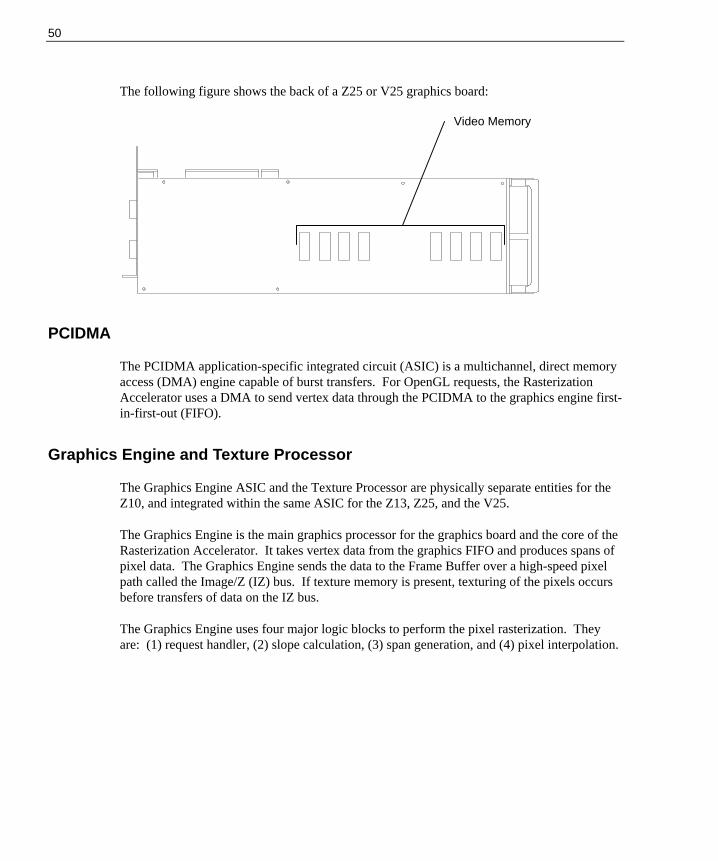
50
The following figure shows the back of a Z25 or V25 graphics board:
PCIDMA
The PCIDMA application-specific integrated circuit (ASIC) is a multichannel, direct memoryaccess (DMA) engine capable of burst transfers. For OpenGL requests, the RasterizationAccelerator uses a DMA to send vertex data through the PCIDMA to the graphics engine first-in-first-out (FIFO).
Graphics Engine and Texture Processor
The Graphics Engine ASIC and the Texture Processor are physically separate entities for theZ10, and integrated within the same ASIC for the Z13, Z25, and the V25.
The Graphics Engine is the main graphics processor for the graphics board and the core of theRasterization Accelerator. It takes vertex data from the graphics FIFO and produces spans ofpixel data. The Graphics Engine sends the data to the Frame Buffer over a high-speed pixelpath called the Image/Z (IZ) bus. If texture memory is present, texturing of the pixels occursbefore transfers of data on the IZ bus.
The Graphics Engine uses four major logic blocks to perform the pixel rasterization. Theyare: (1) request handler, (2) slope calculation, (3) span generation, and (4) pixel interpolation.
Video Memory

51
Request Handler
The request handler monitors the data output of the graphics FIFO. When data arrives, therequest handler analyzes it and writes it to an appropriate processing block. The requesthandler routes vertex data for triangles and lines to the slope calculation block.
Drawing requests (other than vertex data for triangles and lines) such as blits, fills, and bitexpands, bypass the slope calculation and span generation blocks. The request handler routesthis data directly to the pixel interpolation block.
Slope Calculation
The slope calculation block performs the slope calculation part of the rasterization process fortriangles and lines. Floating-point math ensures the accuracy of triangle edges.
The slope calculation block calculates color derivatives, depth derivatives, and edge slopes. Italso adjusts the vertex data to a pixel center for the topmost vertex. The slope calculationblock converts all data to a fixed-point format and routes it to the span generation block.
Span Generation
The span generation block performs the span calculation part of the rasterization process fortriangles and lines. The span generation block determines the leftmost x and y coordinates foreach scanline in a triangle. It also calculates the initial color and depth value for eachscanline, and routes the data to the pixel interpolation block.
Pixel Interpolation
The pixel interpolation block is common for all graphics drawing requests. For trianglemeshes, the pixel interpolation block expands the data from the span generation block to pixeldata by successively adding the x-derivative value to the initial color and depth values (z) foreach span.
The pixel interpolation block also sends the (x, y) address and pixel data to the frame bufferover the IZ bus. The IZ bus is a 64-bit bus with a pixel span protocol to facilitate high datathroughput. This protocol allows burst transfers of pixel data to occur between therasterization accelerator and the frame buffer. The maximum burst size is 4096 pixels.
Texture Processor
A Texture Processor is contained in the Graphics Engine/Texture Processor ASIC on the Z13,Z25, and V25, and as separate ASICs on the Z10. Texturing is the process of applying texturepatterns to the surface of a 3D graphics object to enhance the visual realism of the object, orof an entire scene.

52
The Texture Processor receives instructions from the Graphics Engine via a high-speed busand buffers the instructions in a FIFO to enhance performance. The Texture Processor readsthe instructions from the FIFO, and then translates them into reads and writes of texturememory. Its primary function is to retrieve a group of texels, interpolate among them, andgenerate a final color value. This final color value represents the textured color of a pixel.The Texture Processor places this value into its output FIFO. The Graphics Engine transfersthe pixel’s location and color value from the FIFO to the resolvers for placement into theframe buffer.
Z10 Texturing Accelerator
The Z10 Texturing Accelerator board communicates with texture memory via a 256-bit bus,which provides simultaneous access to eight 32-bit texels. Thirty-two bits are essential forstorage of true-color texels, including Alpha, to match the frame buffer’s true-color pixels.
The following figure shows the front of a Z10 Texturing Accelerator board.
Texture Processors
TextureMemory
TextureMemory
TextureProcessor
RasterizationAcceleratorConnector
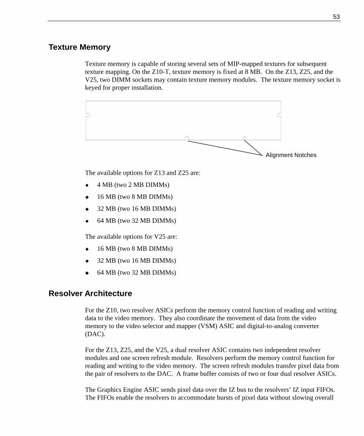
53
Texture Memory
Texture memory is capable of storing several sets of MIP-mapped textures for subsequenttexture mapping. On the Z10-T, texture memory is fixed at 8 MB. On the Z13, Z25, and theV25, two DIMM sockets may contain texture memory modules. The texture memory socket iskeyed for proper installation.
The available options for Z13 and Z25 are:
u 4 MB (two 2 MB DIMMs)
u 16 MB (two 8 MB DIMMs)
u 32 MB (two 16 MB DIMMs)
u 64 MB (two 32 MB DIMMs)
The available options for V25 are:
u 16 MB (two 8 MB DIMMs)
u 32 MB (two 16 MB DIMMs)
u 64 MB (two 32 MB DIMMs)
Resolver Architecture
For the Z10, two resolver ASICs perform the memory control function of reading and writingdata to the video memory. They also coordinate the movement of data from the videomemory to the video selector and mapper (VSM) ASIC and digital-to-analog converter(DAC).
For the Z13, Z25, and the V25, a dual resolver ASIC contains two independent resolvermodules and one screen refresh module. Resolvers perform the memory control function forreading and writing to the video memory. The screen refresh modules transfer pixel data fromthe pair of resolvers to the DAC. A frame buffer consists of two or four dual resolver ASICs.
The Graphics Engine ASIC sends pixel data over the IZ bus to the resolvers’ IZ input FIFOs.The FIFOs enable the resolvers to accommodate bursts of pixel data without slowing overall
Alignment Notches

54
system performance. The pixel data consists of color (Red, Green, Blue, and Alpha - RGBA)and depth (Z) data.
The resolver examines pixel data from the input FIFO and determines if it should write thepixel data to the video memory. The resolver performs Z, mask, stencil (Z13, Z25, and V25only), and alpha tests to determine if data should be written.
The resolver can perform an Arithmetic and Logic Unit (ALU) operation between the sourcedata (data from the Graphics Engine) and the destination data (data in video memory). Theoperations include logical operations and OpenGL style alpha blend operations.
The resolver performs several different types of memory accesses including reads, writes, orread-modify-writes. It conserves memory bandwidth by choosing an appropriate type.
Video Memory
The core of the frame buffer is video memory. Resolvers control the flow of data to and fromthe video memory. The various implementations of RealiZm accelerators have varyingamounts of video memory: 48 VRAMs provide 12 MB of video memory for Z10; 8 SDRAMsprovide 16 MB of video memory for Z13; and 16 SDRAMs provide 32 MB of video memoryfor Z25 and V25.
Video memory stores each pixel with a maximum of 128 bits (Z13, Z25, and V25).
Video Selector and Mapper (Z10 Only)
The display subsystem consists of the VSM ASIC and the DAC. The VSM ASIC receivespixel data from the video memory. It selects the buffer (front or back), and the data (image oroverlay) to display. The video selection planes select one of the VSM’s four video lookuptables (VLTs) to map the image data. The VSM sends the mapped result to the DAC.
Digital-to-Analog Converter
The DAC converts pixel data into an analog voltage and sends it to the monitor for display.The DAC also provides a user-definable 64 x 64 pixel hardware cursor.

55
Geometry Accelerator Components The following describes the major components of the Geometry Accelerator board availablefor use with Z13, Z25, and V25.
PCIDMA
The Geometry Accelerator employs the PCIDMA ASIC as the Peripheral ComponentInterconnect (PCI) bus interface device. This device has an independent DMA engine toaccelerate the transfer of OpenGL data between the host processor and the GeometryAccelerator.
The DMA engine transfers data in bursts into the input/output (I/O) FIFO on the GeometryAccelerator. DMA transfers free the host processor from moving massive amounts ofgraphics data across the PCI bus.
I/O FIFO
The I/O FIFO is a temporary depository for up to 4 KB of data being moved into theGeometry Accelerator. The I/O FIFO allows DMA transfers to proceed at the maximumspeed of the PCI bus or the I/O bus by avoiding stall conditions.
PCIDMA I/O FIFO
DSPs
Sequence

56
DSPs
The core of the Geometry Accelerator is six state of the art digital signal processors (DSPs)operating in parallel. These are 32-bit floating point processors, each capable of executing120 million floating-point operations per second (MFLOPS). Each DSP contains 256 KB ofhigh-speed RAM. Each DSP also has an advanced I/O system with six communication portsand ten DMA engines. This I/O system allows continual flow of data through the multipleDSPs and to the Sequence Controller with minimal host processor overhead.
Sequence Controller
The multiple instruction multiple data (MIMD) architecture of the Geometry Acceleratorallows incoming data to be processed concurrently and independently by each of the six DSPs.This means that the DSP that processes the first input request may not generate the first outputrequest. Data moves through the DSPs at different rates, depending upon the complexity ofthe request.
Since the order of drawing operations must be maintained, this out of order data must beplaced back into the order that it was received. This task is the responsibility of the SequenceController. The Sequence Controller receives data from each of the six DSPs via fourcommunication ports. The Sequence Controller time-orders the data, and then uses a DMA towrite the data directly to the Rasterization Accelerator via the Vertex data bus. The SequenceController also handles some clipping, and controls the flow of data to multiple RasterizationAccelerators for dual screen systems.

57
6 Specifications
Standard specifications for RealiZm graphics accelerators are subject to change withoutnotice.
GraphicsAccelerator
Max ScreenResolution Frame Buffer Texture Memory
GeometryAcceleration
Z10 1.0 Mpixels 12 MB VRAM
Z10-T 1.0 Mpixels 12 MB VRAM 8 MB DRAM
Z13 1.3 Mpixels 16 MB SDRAM
Z13-T 1.3 Mpixels 16 MB SDRAM 4 - 64 MB SDRAM
Z13-G 1.3 Mpixels 16 MB SDRAM ✔
Z13-GT 1.3 Mpixels 16 MB SDRAM 4 - 64 MB SDRAM ✔
Z25 2.5 Mpixels 32 MB SDRAM
Z25-T 2.5 Mpixels 32 MB SDRAM 4 - 64 MB SDRAM
Z25-G 2.5 Mpixels 32 MB SDRAM ✔
Z25-GT 2.5 Mpixels 32 MB SDRAM 4 - 64 MB SDRAM ✔
V25 2.5 Mpixels 32 MB SDRAM
V25-T 2.5 Mpixels 32 MB SDRAM 16 - 64 MB SDRAM
V25-G 2.5 Mpixels 32 MB SDRAM ✔
V25-GT 2.5 Mpixels 32 MB SDRAM 16 - 64 MB SDRAM ✔
Cooling System (Z25 and V25) The Z25 and V25 graphics board includes high-power components that require cooling. Aduct covers the board and directs air over the components from two fans mounted at one endof the graphics board. Air from inside the assembly moves outside the system at the I/O endof the graphics board.
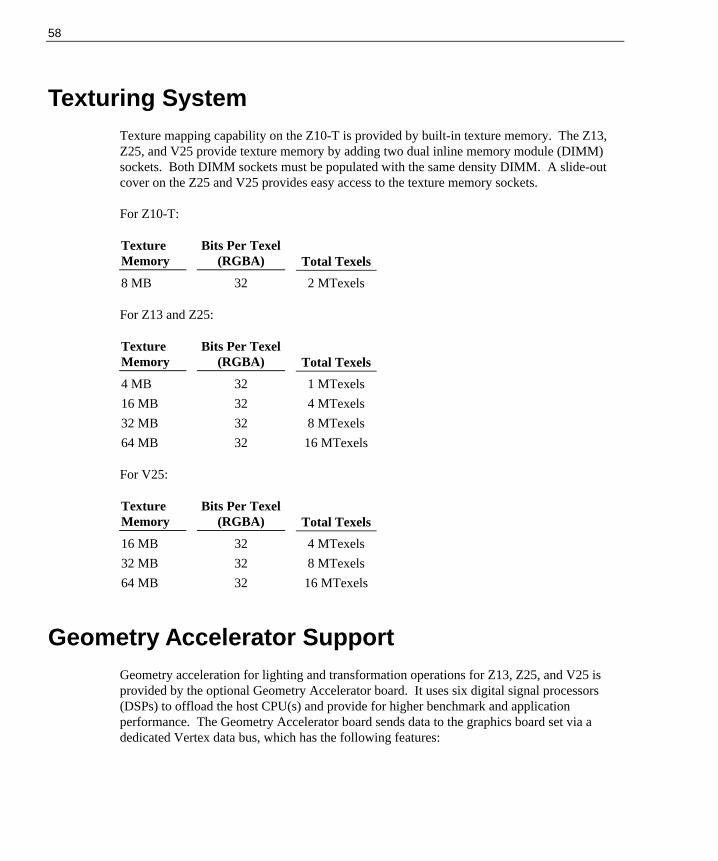
58
Texturing System Texture mapping capability on the Z10-T is provided by built-in texture memory. The Z13,Z25, and V25 provide texture memory by adding two dual inline memory module (DIMM)sockets. Both DIMM sockets must be populated with the same density DIMM. A slide-outcover on the Z25 and V25 provides easy access to the texture memory sockets.
For Z10-T:
TextureMemory
Bits Per Texel(RGBA) Total Texels
8 MB 32 2 MTexels
For Z13 and Z25:
TextureMemory
Bits Per Texel(RGBA) Total Texels
4 MB 32 1 MTexels
16 MB 32 4 MTexels
32 MB 32 8 MTexels
64 MB 32 16 MTexels
For V25:
TextureMemory
Bits Per Texel(RGBA) Total Texels
16 MB 32 4 MTexels
32 MB 32 8 MTexels
64 MB 32 16 MTexels
Geometry Accelerator Support Geometry acceleration for lighting and transformation operations for Z13, Z25, and V25 isprovided by the optional Geometry Accelerator board. It uses six digital signal processors(DSPs) to offload the host CPU(s) and provide for higher benchmark and applicationperformance. The Geometry Accelerator board sends data to the graphics board set via adedicated Vertex data bus, which has the following features:

59
u Dedicated 60-pin ribbon cable interface
u Peak transfer rate of 132 MB per second
u Up to two graphics board sets can be interfaced to a single Geometry Accelerator board
Monitor Resolutions Z10, Z13, Z25, and V25 supports standard multi-sync monitors, including the Intergraph17-inch and 21-inch monitors, at the following resolutions and maximum refresh rates (Hz).
Resolution Z10 Z13 Z25/V25
640 x 480 85 85 85
800 x 600 85 85 85
1024 x 768 85 85 85
1152 x 864 76 85 85
1280 x 960 85 85
1280 x 1024 85 85
1600 x 1200 75
1824 x 1368 65
Z13, Z25, and V25 support Intergraph InterVue-27 monitors at the following resolutions andmaximum refresh rates (Hz).
Resolution Z13 Z25/V25
640 x 480 151 151
800 x 600 123 123
1024 x 768 98 98
1280 x 960 79 79
1280 x 1024 74 74
1600 x 1200 64
1600 x 1280 60

60
Interfaces RealiZm graphics accelerators have three interface connections: a video output port, a VGAinput port, and a stereo sync output port.
Video Output Port
The video output port provides connection to the monitor. The recommended cable length isless than three meters. The following table provides the pin connections for the video outputport.
Z10 Signal Name Z13/Z25/V25 Signal Name Pin
Red Analog Video Red Analog Video 1
Green Analog Video Green Analog Video 2
Blue Analog Video Blue Analog Video 3
Ground Monitor ID [2] 4
Ground Ground 5
Ground Ground 6
Ground Ground 7
Ground Ground 8
No Connect Supply +5V 9
Ground Ground 10
Ground Monitor ID [0] 11
Ground Monitor ID [1] 12
Horizontal Sync Horizontal Sync 13
Vertical Sync Vertical Sync 14
Ground Monitor ID [3] 15
The video output port is female, 15-pin, D-Sub as shown in the following figure.
5
10
1
6
15
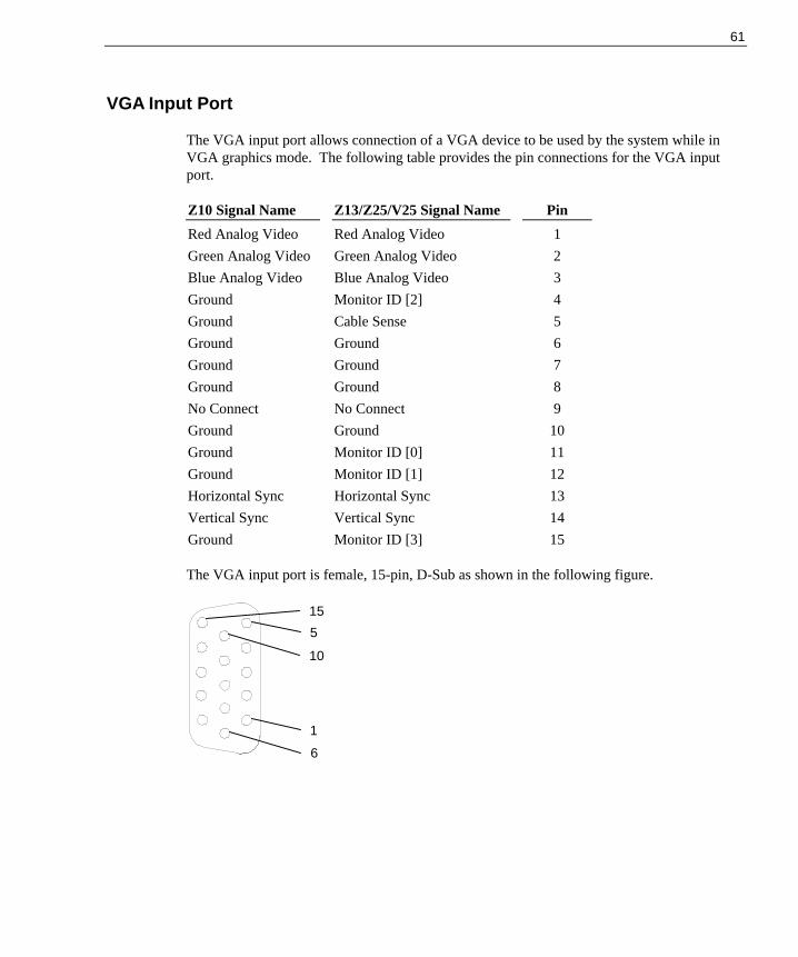
61
VGA Input Port
The VGA input port allows connection of a VGA device to be used by the system while inVGA graphics mode. The following table provides the pin connections for the VGA inputport.
Z10 Signal Name Z13/Z25/V25 Signal Name Pin
Red Analog Video Red Analog Video 1
Green Analog Video Green Analog Video 2
Blue Analog Video Blue Analog Video 3
Ground Monitor ID [2] 4
Ground Cable Sense 5
Ground Ground 6
Ground Ground 7
Ground Ground 8
No Connect No Connect 9
Ground Ground 10
Ground Monitor ID [0] 11
Ground Monitor ID [1] 12
Horizontal Sync Horizontal Sync 13
Vertical Sync Vertical Sync 14
Ground Monitor ID [3] 15
The VGA input port is female, 15-pin, D-Sub as shown in the following figure.
5
10
1
6
15

62
Stereo Sync Output Port
The stereo sync output port provides connection to the LCD shutter glasses’ emitter module.The following table provides the pin connections for the stereo sync output port.
Signal Name Pin
Ground 1
Ground 2
+12V 3
Stereo Sync 4
No Connect 5
The stereo port is female, 5-pin, mini-DIN as shown in the following figure.
4
3
2
1
5
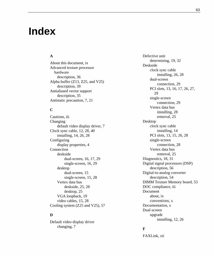
63
Index
A
About this document, ixAdvanced texture processor
hardwaredescription, 36
Alpha buffer (Z13, Z25, and V25)description, 39
Antialiased vector supportdescription, 35
Antistatic precaution, 7, 21
C
Cautions, iiiChanging
default video display driver, 7Clock sync cable, 12, 28, 40
installing, 14, 26, 28Configuring
display properties, 4Connection
desksidedual-screen, 16, 17, 29single-screen, 16, 29
desktopdual-screen, 15single-screen, 15, 28
Vertex data busdeskside, 25, 28desktop, 25
VGA loopback, 19video cables, 15, 28
Cooling system (Z25 and V25), 57
D
Default video display driverchanging, 7
Defective unitdetermining, 19, 32
Desksideclock sync cable
installing, 26, 28dual-screen
connection, 29PCI slots, 13, 16, 17, 26, 27,
29single-screen
connection, 29Vertex data bus
installing, 28removal, 25
Desktopclock sync cable
installing, 14PCI slots, 13, 15, 26, 28single-screen
connection, 28Vertex data bus
removal, 25Diagnostics, 18, 31Digital signal processors (DSP)
description, 56Digital-to-analog converter
description, 54DIMM Texture Memory board, 53DOC compliance, iiiDocument
about, ixconventions, x
Documentation, xDual-screen
upgradeinstalling, 12, 26
F
FAXLink, xii
64
FCC compliance, iiiFrame Buffer, 37, 42
alpha buffer (Z13, Z25, andV25), 39
gamma correction, 39Genlock support for dual
monitors, 40hardware cursor, 39high-resolution Z buffer, 38high-speed screen refresh, 40multiple video lookup tables,
39multiple video resolutions, 39stencil buffer (Z13, Z25, and
V25), 38stereoscopic viewing, 39true-color image buffer, 38video plane sets, 37
84/90 bits per pixel, 37window-mode double
buffering, 39
G
Gamma correctiondescription, 39
Genlock support for dual monitorsdescription, 40
Geometry Accelerator, 55block diagram, 46board, 55board installation
deskside, 25, 26desktop, 25, 26
components, 55DSPs, 56I/O FIFO, 55PCIDMA, 55Sequence Controller, 56
features and functions, 45high-speed graphics DMA
engine, 45MIMD DSP architecture,
45sequence controller, 45
industry standard PCI bus, 45support, 58technical description, 45
Getting started, 1changing default video display
driver, 7configuring display properties,
4RealiZm
configurations, 2features and functions, 1graphics accelerators, 1
RenderGL Run-Time Library,4
starting Windows NT, 3Gouraud shading support
description, 35Graphics acceleration processing
block diagram, 41Graphics Engine, 35
antialiased vector support, 35Gouraud shading support, 35high-level vertex interface, 35sub-pixel accuracy, 36symbolized vector support, 35window clipping (Z13, Z25,
and V25), 36Graphics Engine and Texture
Processordescription, 50pixel interpolation, 51request handler, 51slope calculation, 51span generation, 51texture processor, 51
H
Hardware cursor
65
description, 39Hardware description, 47
Geometry Accelerator, 55digital signal processors
(DSPs), 56I/O FIFO, 55PCIDMA, 55sequence controller, 56
Rasterization Accelerator, 47digital-to-analog
converter, 54Graphics Engine and
Texture Processor, 50PCIDMA, 50resolver architecture, 53video memory, 54video selector and mapper,
54Z10, 47Z13, 48Z25 and V25, 49
Texture memory, 53Z10 Texturing Accelerator, 52
High-level vertex interfacedescription, 35
High-resolution Z bufferdescription, 38
High-speedDMA engine
description, 34graphics DMA engine
description, 45screen refresh
description, 40
I
I/O FIFOdescription, 55
Industry standard PCI busdescription, 45
Installingclock sync cable, 12, 14, 26,
28dual-screen upgrade
Z10, 12Z13, Z25, or V25, 26
texture memory, 22texturing accelerator, 8Vertex data bus, 28video display driver, 17, 30Z13, Z25, or Geometry
Accelerator, 24Interfaces, 60
Geometry Accelerator (Z13,Z25, and V25)
description, 35stereo sync output port, 62VGA input port, 61video output port, 60
Intergraphbulletin board service, xiFAXLink, xiiInternet, xii
Internet, xii
L
Last known good, 19, 31
M
MIMD DSP architecturedescription, 45
MIP-mapping support with trilinearinterpolation
description, 37Monitor resolutions, 59Multiple video
lookup tablesdescription, 39
resolutionsdescription, 39
O
Operating system

66
information, x
P
Packing listdual-screen option
verifying, 12, 26PCI bus interface
description, 34high-speed DMA engine, 34interface for Geometry
Accelerator (Z13, Z25, andV25), 35
PCI-compatible bus interface,34
PCI slotsdeskside, 13, 16, 17, 26, 27, 29desktop, 13, 15, 26, 28
PCI-compatible bus interfacedescription, 34
PCIDMAdescription, 50, 55
Pinoutsstereo sync output port, 62VGA input port, 61video output port, 60
Pixel interpolationdescription, 51
Pixelization Accelerator, 41Port
stereo sync output, 62VGA input, 61video output, 60
Precautions, 7, 21
R
Rasterization Acceleratorcomponents, 47features, 33functions, 40technical description, 33Z10, 47
block diagram, 43board, 47
Z13, 48
back view, 48front view, 48
Z13, Z25, and V25block diagram, 44
Z25 and V25, 49back view, 50front view, 49
RealiZmconfigurations, 2features and functions, 1graphics accelerators, 1
Removingclock sync cable, 25Vertex data bus, 25
RenderGL Run-Time Librarygetting started, 4
ReplacingZ10 or Z10-T, 10Z13, Z25, or Geometry
Accelerator, 24Z13, Z25, V25 or Geometry
Accelerator, 24Request handler
description, 51Resolver architecture
description, 53
S
Selectinglast known good, 19, 31VGA mode, 19, 32
Sequence controllerdescription, 45, 56
Slope calculationdescription, 51
Span generationdescription, 51

67
Specifications, 57cooling system (Z25 and V25),
57Geometry Accelerator support,
58interfaces, 60monitor resolutions, 59
InterVue-27, 59multi-sync, 59
RealiZm graphics accelerators,57
texturing system, 58Stencil buffer (Z13, Z25, and V25)
description, 38Stereo sync output port, 62Stereoscopic viewing
description, 39Sub-pixel accuracy
description, 36Support
bulletin board service, xiFAXLink, xiiInternet, xiitelephone, xi
Symbolized vector supportdescription, 35
Systempowering on, 3
T
Technical description, 33Geometry Accelerator features
and functions, 45high-speed graphics DMA
engine, 45MIMD DSP architecture,
45sequence controller, 45
Rasterization Acceleratorfeatures, 33
Frame Buffer, 37Graphics Engine, 35PCI bus interface, 34Texture Processor, 36
Rasterization Acceleratorfunctions, 40
Frame Buffer, 42Pixelization Accelerator,
41Texture Processor, 42
Telephone support, xiTexture memory
description, 36, 53installing, 22socket
V25, 23Z13, 22Z25, 23
Texture Processor, 36, 42advanced texture processor
hardware, 36description, 51MIP-mapping support with
trilinear interpolation, 37texture memory, 36
Texturing acceleratorinstalling, 8Z10, 52
Texturing system, 58Training, xTroubleshooting, 18, 31True-color image buffer
description, 38
U
Upgrading or replacingZ10, 7Z13, Z25, V25, 21
Usable video resolution, 19, 31
V
Vertex data busdeskside, 25, 28desktop, 25installing, 28removal, 25
68
VGAconnection
loopback cable, 19mode, 19, 32
VGA input port, 61pinouts, 61
Videocables
connecting, 15, 28display
properties, 4troubleshooting, 18, 31
display driverinstalling, 17, 30
memorydescription, 54
planesdescription, 37
random access memory(VRAM), 54
resolutionusable, 19, 31
selector and mapper(VSM)(Z10 Only)
description, 54Video output port, 60
pinouts, 60
W
Warnings, iiiWindow clipping (Z13, Z25, and
V25)description, 36
Window-mode double-bufferingdescription, 39
Windows NTstarting, 3
Windows NT Workstationinformation, x
Z
Z10 Texturing Acceleratorboard, 52
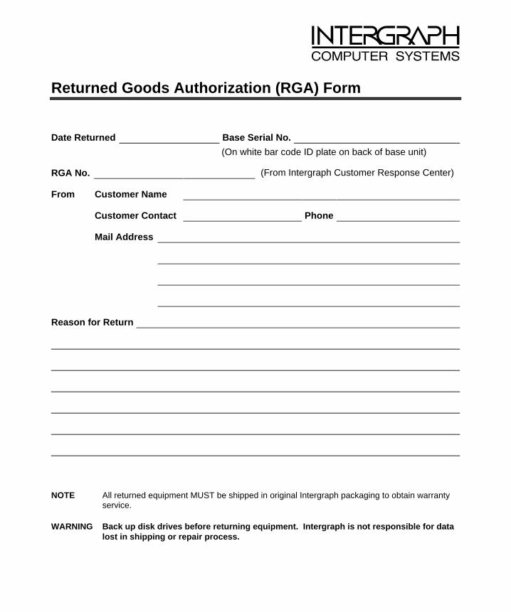
Returned Goods Authorization (RGA) Form
Date Returned Base Serial No.
(On white bar code ID plate on back of base unit)
RGA No. (From Intergraph Customer Response Center)
From Customer Name
Customer Contact Phone
Mail Address
Reason for Return
NOTE All returned equipment MUST be shipped in original Intergraph packaging to obtain warrantyservice.
WARNING Back up disk drives before returning equipment. Intergraph is not responsible for datalost in shipping or repair process.

Warranty Procedure
Some malfunctioning equipment cannot be repaired in the field, and you must return it to Intergraph forrepair. Follow these steps to obtain a Returned Goods Authorization (RGA) log number and return themalfunctioning equipment.
1. Determine the serial number of the system. The serial number is located on the white bar codeidentification label on the back of the base unit.
2. Call the Intergraph Customer Response Center at 1-800-633-7248, and identify your call to theoperator as a Warranty Call. After giving the operator the serial number of the system, you will beassigned a RGA log number.
3. Complete the RGA Form on the previous page, entering the RGA log number obtained from theCustomer Response Center. Ensure that the address in the From section is the location to which youwant the equipment to be returned.
4. Place the RGA form in the box containing the equipment. This form must accompany returnedequipment.
5. Secure a Repair Depot address label from the next page to the box containing the equipment.
6. Ship the box containing the equipment to Intergraph.
When the service activity has been completed by Intergraph, the repaired or replaced equipment will beshipped to the address listed on the RGA Form.
NOTE Parts damaged during shipping and parts not covered by the warranty are liable for repaircharges.

TO Repair Depot RGA No. ________________________
Intergraph Corporation
9805 Kellner Road
Huntsville AL 35894
TO Repair Depot RGA No. ________________________
Intergraph Corporation
9805 Kellner Road
Huntsville AL 35894
TO Repair Depot RGA No. ________________________
Intergraph Corporation
9805 Kellner Road
Huntsville AL 35894


![3[1]. Graphics Hardware II](https://static.fdocuments.in/doc/165x107/547834d45906b55f318b4785/31-graphics-hardware-ii.jpg)