Realistic Shape Optimizeryvonet.florent.free.fr/SERVEUR/COURS CATIA/CATIA Shape Design a… · the...
28
Instructor Notes: Copyright DASSAULT SYSTEMES 1 Copyright DASSAULT SYSTEMES Realistic Shape Optimizer CATIA V5 Training Foils Version 5 Release 19 January 2009 EDU_CAT_EN_RSO_FI_V5R19
Transcript of Realistic Shape Optimizeryvonet.florent.free.fr/SERVEUR/COURS CATIA/CATIA Shape Design a… · the...
Instructor Notes:
Copyright DASSAULT SYSTEMES 1
��������������
Cop
yrig
ht D
AS
SA
ULT
SY
STE
ME
S
Realistic Shape Optimizer
CATIA V5 TrainingFoils
Version 5 Release 19January 2009
EDU_CAT_EN_RSO_FI_V5R19
Instructor Notes:
Copyright DASSAULT SYSTEMES 2
��������������
Cop
yrig
ht D
AS
SA
ULT
SY
STE
ME
S
About this courseObjectives of the courseUpon completion of this course you will be able to:- Deform a surface using the Displacement file resulting from Finite Element Analysis
Targeted audienceSurface designers, Tooling designers
PrerequisitesStudents attending this course should be familiar with the basics of wireframe and surfaces creation
4 hours
Instructor Notes:
Copyright DASSAULT SYSTEMES 3
��������������
Cop
yrig
ht D
AS
SA
ULT
SY
STE
ME
S
Table of Contents
Introduction to Realistic Shape Optimizer 4Why Do You Need RSO? 5Warning 7Accessing the Workbench 8
Surface Deformation 9Digitized Morphing: Inputs 10Displacement Files 11User Interface 13Update Digitized Morphing 17
Exercises 18Exercise 1: Blade 19Exercise 2: Stamped Part 22Exercise 3: Plane Wing 25
Instructor Notes:
Copyright DASSAULT SYSTEMES 4
��������������
Cop
yrig
ht D
AS
SA
ULT
SY
STE
ME
S
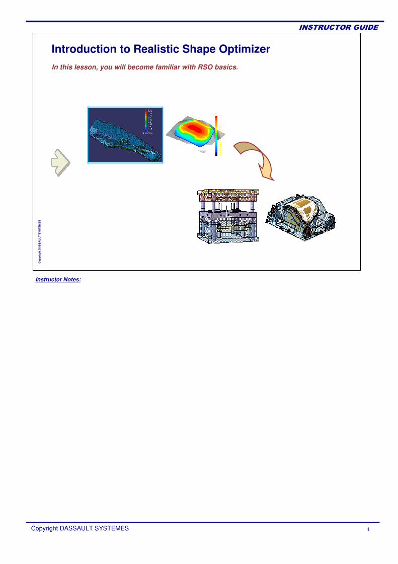
Introduction to Realistic Shape OptimizerIn this lesson, you will become familiar with RSO basics.
Instructor Notes:
Copyright DASSAULT SYSTEMES 5
��������������
Cop
yrig
ht D
AS
SA
ULT
SY
STE
ME
S
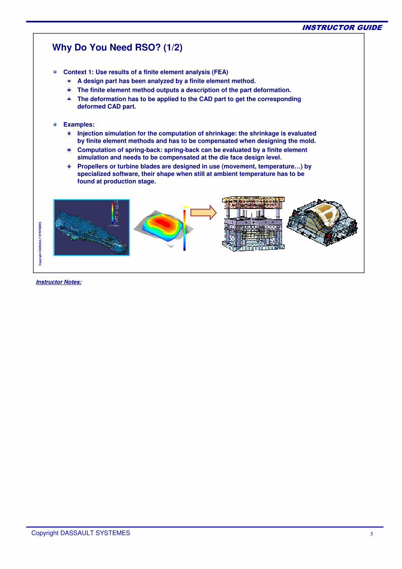
Why Do You Need RSO? (1/2)
Context 1: Use results of a finite element analysis (FEA)A design part has been analyzed by a finite element method.The finite element method outputs a description of the part deformation.The deformation has to be applied to the CAD part to get the corresponding deformed CAD part.
Examples:Injection simulation for the computation of shrinkage: the shrinkage is evaluated by finite element methods and has to be compensated when designing the mold.Computation of spring-back: spring-back can be evaluated by a finite element simulation and needs to be compensated at the die face design level.Propellers or turbine blades are designed in use (movement, temperature…) by specialized software, their shape when still at ambient temperature has to be found at production stage.
Instructor Notes:
Copyright DASSAULT SYSTEMES 6
��������������
Cop
yrig
ht D
AS
SA
ULT
SY
STE
ME
S
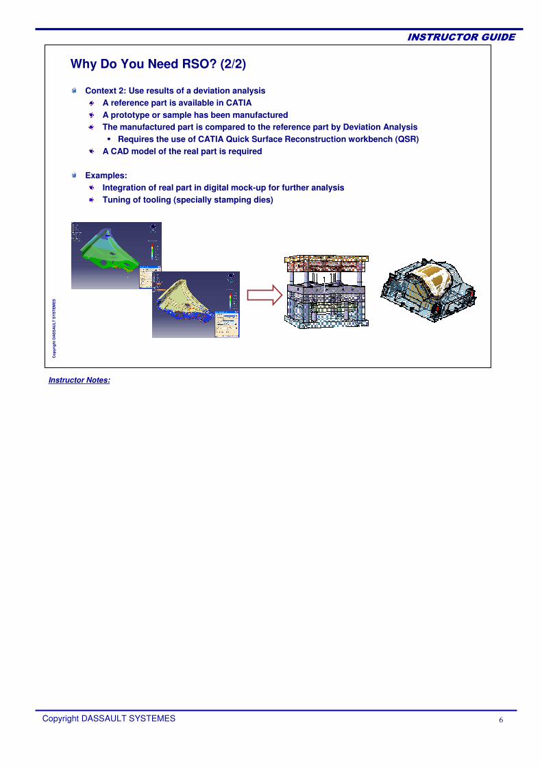
Why Do You Need RSO? (2/2)
Context 2: Use results of a deviation analysisA reference part is available in CATIA A prototype or sample has been manufacturedThe manufactured part is compared to the reference part by Deviation Analysis� Requires the use of CATIA Quick Surface Reconstruction workbench (QSR)
A CAD model of the real part is required
Examples:Integration of real part in digital mock-up for further analysis Tuning of tooling (specially stamping dies)
Instructor Notes:
Copyright DASSAULT SYSTEMES 7
��������������
Cop
yrig
ht D
AS
SA
ULT
SY
STE
ME
S
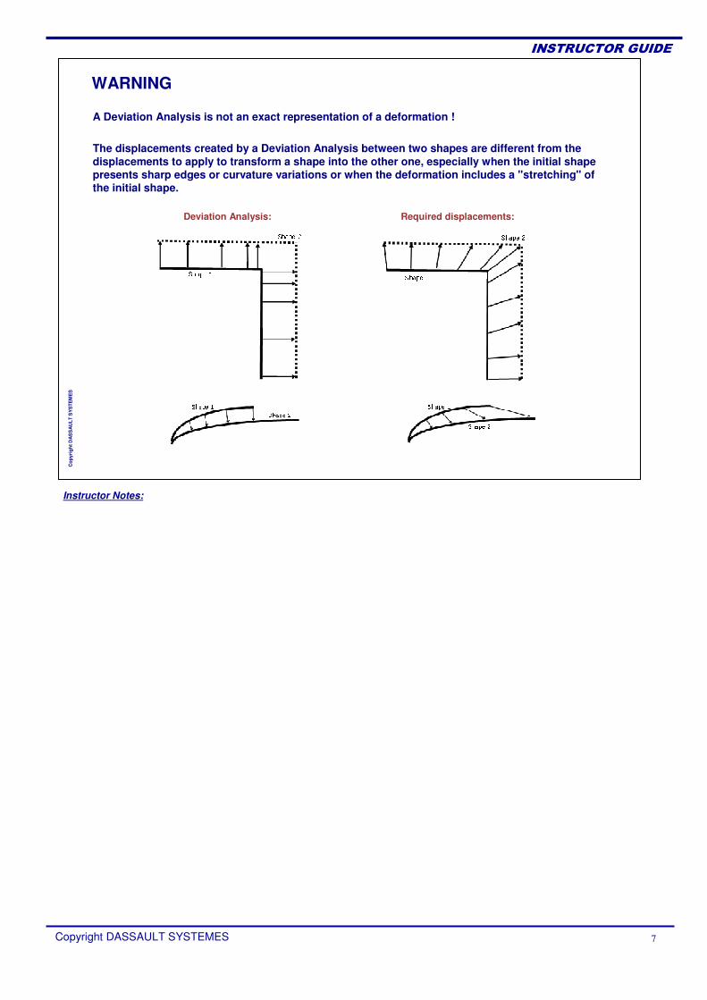
WARNING
A Deviation Analysis is not an exact representation of a deformation !
The displacements created by a Deviation Analysis between two shapes are different from the displacements to apply to transform a shape into the other one, especially when the initial shape presents sharp edges or curvature variations or when the deformation includes a "stretching" of the initial shape.
Deviation Analysis: Required displacements:
Instructor Notes:
Copyright DASSAULT SYSTEMES 8
��������������
Cop
yrig
ht D
AS
SA
ULT
SY
STE
ME
S
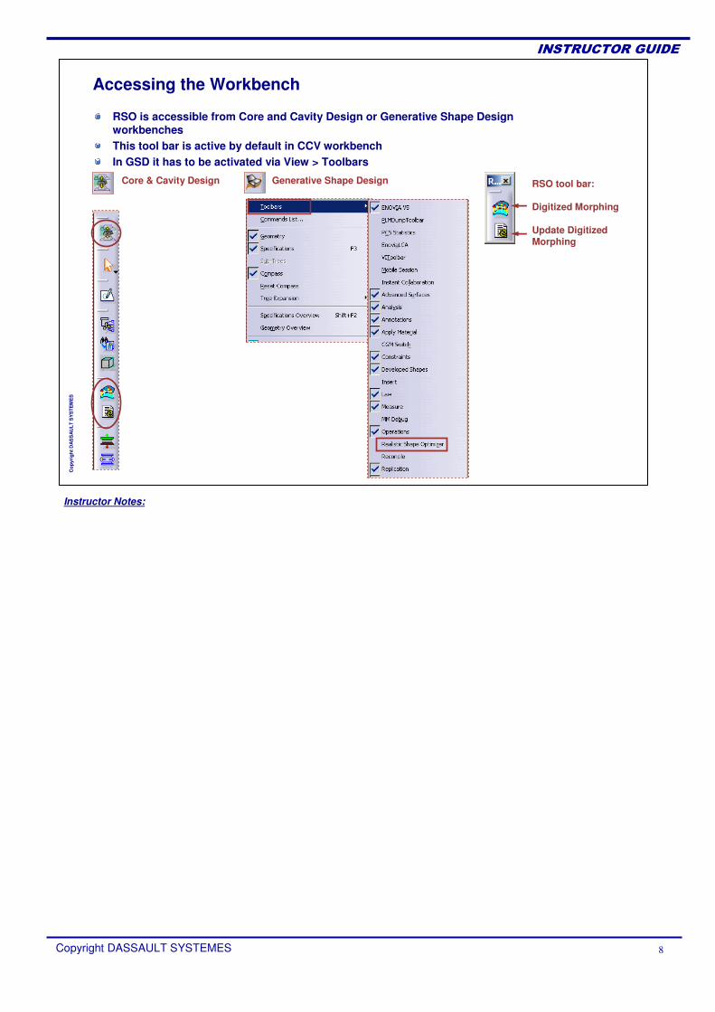
RSO is accessible from Core and Cavity Design or Generative Shape Design workbenchesThis tool bar is active by default in CCV workbench In GSD it has to be activated via View > Toolbars
Accessing the Workbench
RSO tool bar:
Digitized Morphing
Update Digitized Morphing
Core & Cavity Design Generative Shape Design
Instructor Notes:
Copyright DASSAULT SYSTEMES 9
��������������
Cop
yrig
ht D
AS
SA
ULT
SY
STE
ME
S
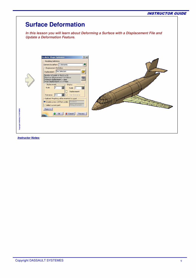
Surface DeformationIn this lesson you will learn about Deforming a Surface with a Displacement File and Update a Deformation Feature.
Instructor Notes:
Copyright DASSAULT SYSTEMES 10
��������������
Cop
yrig
ht D
AS
SA
ULT
SY
STE
ME
S
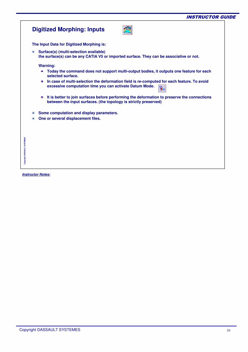
Surface(s) (multi-selection available)the surface(s) can be any CATIA V5 or imported surface. They can be associative or not.
Warning:Today the command does not support multi-output bodies, it outputs one feature for each selected surface.In case of multi-selection the deformation field is re-computed for each feature. To avoid excessive computation time you can activate Datum Mode.
It is better to join surfaces before performing the deformation to preserve the connections between the input surfaces. (the topology is strictly preserved)
Some computation and display parameters.One or several displacement files.
Digitized Morphing: Inputs
The Input Data for Digitized Morphing is:
Instructor Notes:
Copyright DASSAULT SYSTEMES 11
��������������
Cop
yrig
ht D
AS
SA
ULT
SY
STE
ME
S
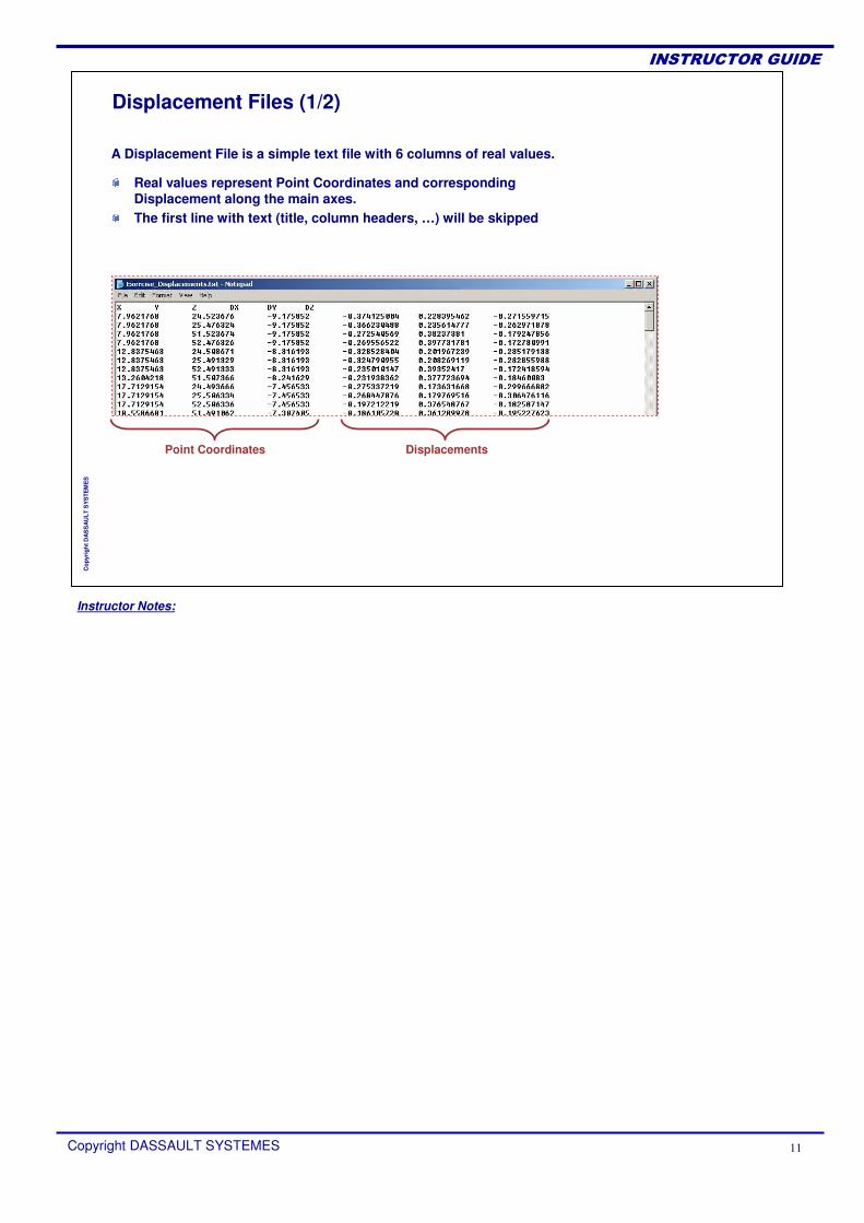
Displacement Files (1/2)
Point Coordinates Displacements
Real values represent Point Coordinates and corresponding Displacement along the main axes.The first line with text (title, column headers, …) will be skipped
A Displacement File is a simple text file with 6 columns of real values.
Instructor Notes:
Copyright DASSAULT SYSTEMES 12
��������������
Cop
yrig
ht D
AS
SA
ULT
SY
STE
ME
S
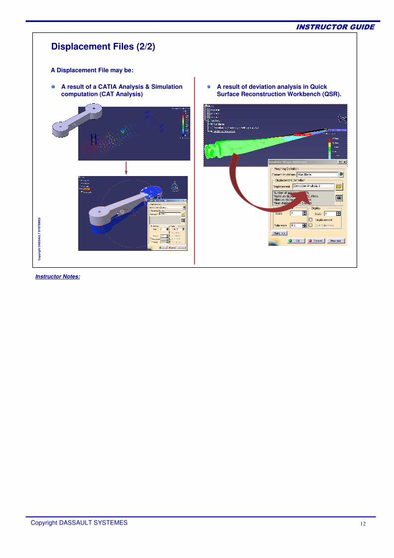
Displacement Files (2/2)
A result of deviation analysis in Quick Surface Reconstruction Workbench (QSR).
A Displacement File may be:
A result of a CATIA Analysis & Simulation computation (CAT Analysis)
Instructor Notes:
Copyright DASSAULT SYSTEMES 13
��������������
Cop
yrig
ht D
AS
SA
ULT
SY
STE
ME
S
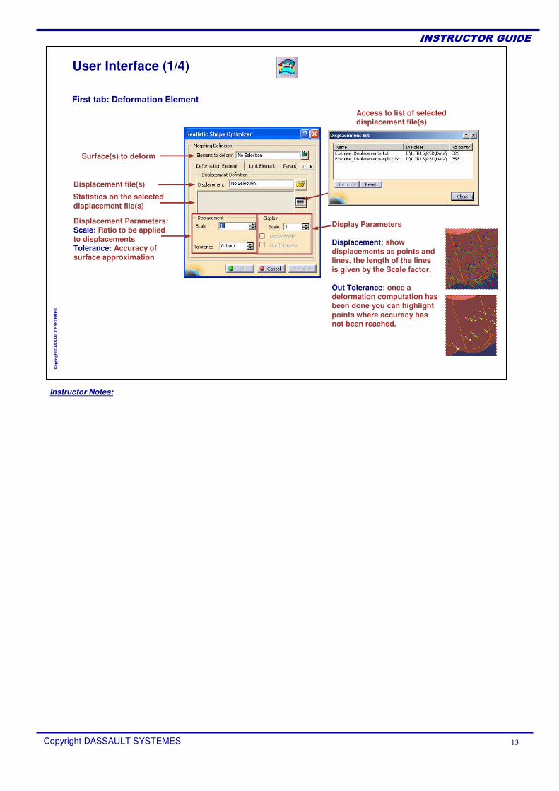
User Interface (1/4)
Surface(s) to deform
Displacement file(s)
Access to list of selected displacement file(s)
Statistics on the selected displacement file(s)
Displacement Parameters:Scale: Ratio to be applied to displacementsTolerance: Accuracy of surface approximation
First tab: Deformation Element
Display Parameters
Displacement: show displacements as points and lines, the length of the lines is given by the Scale factor.
Out Tolerance: once a deformation computation has been done you can highlight points where accuracy has not been reached.
Instructor Notes:
Copyright DASSAULT SYSTEMES 14
��������������
Cop
yrig
ht D
AS
SA
ULT
SY
STE
ME
S
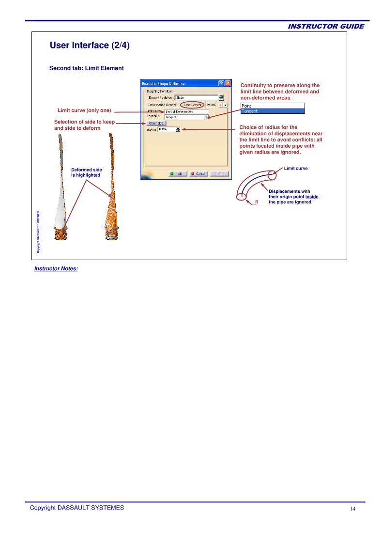
User Interface (2/4)
Second tab: Limit Element
Limit curve (only one)
Continuity to preserve along the limit line between deformed and non-deformed areas.
Choice of radius for the elimination of displacements near the limit line to avoid conflicts: all points located inside pipe with given radius are ignored.
Selection of side to keep and side to deform
Deformed sideis highlighted
Limit curve
Displacements with their origin point insidethe pipe are ignoredR
Instructor Notes:
Copyright DASSAULT SYSTEMES 15
��������������
Cop
yrig
ht D
AS
SA
ULT
SY
STE
ME
S
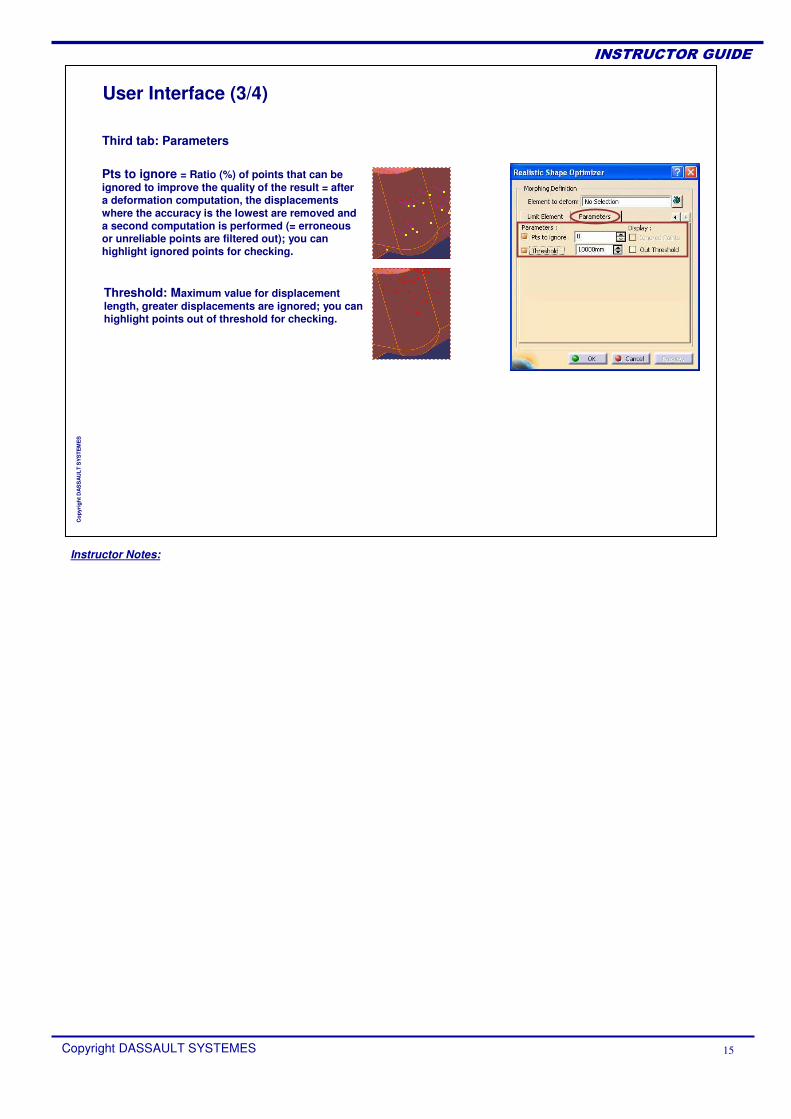
User Interface (3/4)
Threshold: Maximum value for displacement length, greater displacements are ignored; you can highlight points out of threshold for checking.
Pts to ignore = Ratio (%) of points that can be ignored to improve the quality of the result = after a deformation computation, the displacements where the accuracy is the lowest are removed and a second computation is performed (= erroneous or unreliable points are filtered out); you can highlight ignored points for checking.
Third tab: Parameters
Instructor Notes:
Copyright DASSAULT SYSTEMES 16
��������������
Cop
yrig
ht D
AS
SA
ULT
SY
STE
ME
S
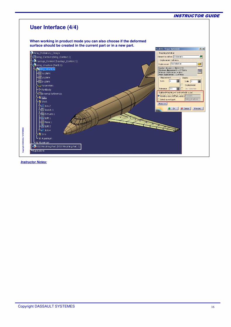
User Interface (4/4)
When working in product mode you can also choose if the deformedsurface should be created in the current part or in a new part.
Instructor Notes:
Copyright DASSAULT SYSTEMES 17
��������������
Cop
yrig
ht D
AS
SA
ULT
SY
STE
ME
S
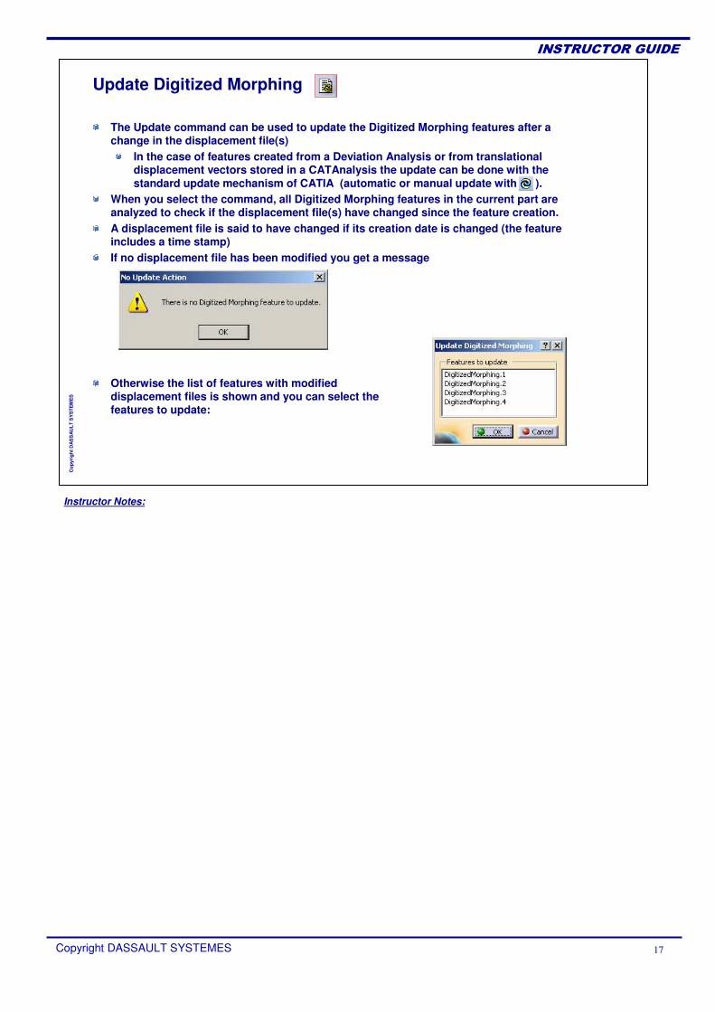
Otherwise the list of features with modified displacement files is shown and you can select the features to update:
Update Digitized Morphing
The Update command can be used to update the Digitized Morphing features after a change in the displacement file(s)
In the case of features created from a Deviation Analysis or from translational displacement vectors stored in a CATAnalysis the update can be done with the standard update mechanism of CATIA (automatic or manual update with ).
When you select the command, all Digitized Morphing features in the current part are analyzed to check if the displacement file(s) have changed since the feature creation.A displacement file is said to have changed if its creation date is changed (the feature includes a time stamp)If no displacement file has been modified you get a message
Instructor Notes:
Copyright DASSAULT SYSTEMES 18
��������������
Cop
yrig
ht D
AS
SA
ULT
SY
STE
ME
S
ExercisesYou will apply the theory learnt in the following exercises.
Exercise 1: BladeExercise 2: Stamped PartExercise 3: Plane Wing
Instructor Notes:
Copyright DASSAULT SYSTEMES 19
��������������
Cop
yrig
ht D
AS
SA
ULT
SY
STE
ME
S
Exercise 1Blade
30 min
The goal of the exercise is to deform a CATIA V5 surface using an external displacement file, for example resulting from a finite element analysis.
Instructor Notes:
Copyright DASSAULT SYSTEMES 20
��������������
Cop
yrig
ht D
AS
SA
ULT
SY
STE
ME
S
Exercise 1: BladeStep 1: Deform surface
15 min.
In this step, you will open the part file to process, then apply a deformation defined by a displacement file.
Instructor Notes:
Copyright DASSAULT SYSTEMES 21
��������������
Cop
yrig
ht D
AS
SA
ULT
SY
STE
ME
S
Exercise 1: BladeStep 2: Update deformation
15 min.
Now you will modify the displacement file and update the Digitized Morphing feature.
Instructor Notes:
Copyright DASSAULT SYSTEMES 22
��������������
Cop
yrig
ht D
AS
SA
ULT
SY
STE
ME
S
Exercise 2Stamped Part
30 min
The goal of the exercise is to deform a CATIA V5 surface using a deviation analysis computed with CATIA Quick Surface Reconstruction workbench.
Instructor Notes:
Copyright DASSAULT SYSTEMES 23
��������������
Cop
yrig
ht D
AS
SA
ULT
SY
STE
ME
S
Exercise 2: Stamped PartStep 1 : Deform surface
15 min.
In this step, you will open the part file to process, then apply a deformation defined by a deviation analysis created in CATIA Quick Surface Reconstruction workbench.
Instructor Notes:
Copyright DASSAULT SYSTEMES 24
��������������
Cop
yrig
ht D
AS
SA
ULT
SY
STE
ME
S
Exercise 2: Stamped PartStep 2: Update deformation
15 min.
In this step, you will modify the deviation analysis computation parameters and update the deformed shape.
Instructor Notes:
Copyright DASSAULT SYSTEMES 25
��������������
Cop
yrig
ht D
AS
SA
ULT
SY
STE
ME
S
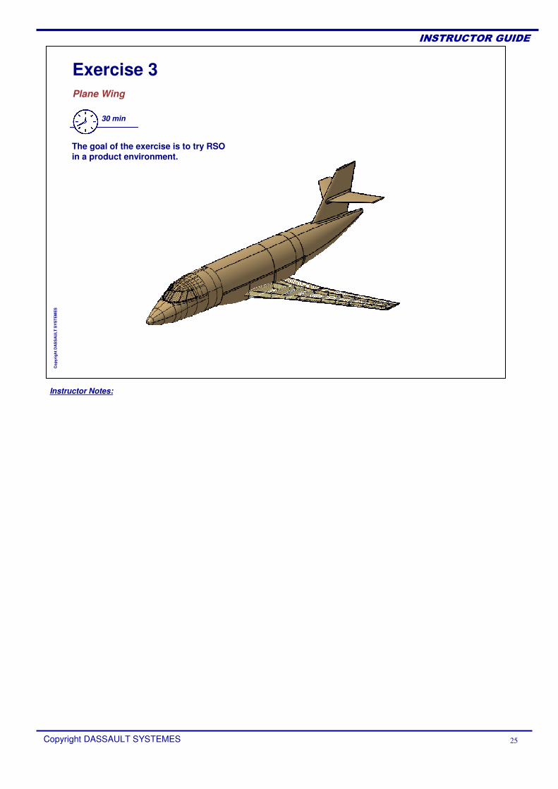
Exercise 3Plane Wing
30 min
The goal of the exercise is to try RSO in a product environment.
Instructor Notes:
Copyright DASSAULT SYSTEMES 26
��������������
Cop
yrig
ht D
AS
SA
ULT
SY
STE
ME
S
Exercise 3: Plane WingStep 1: Deform surface
15 min.
In this step, you will open the CATAnalysisdocument, then apply a deformation defined by the result of the load simulation.
Instructor Notes:
Copyright DASSAULT SYSTEMES 27
��������������
Cop
yrig
ht D
AS
SA
ULT
SY
STE
ME
S
Exercise 3: Plane WingStep 2: Update deformation
15 min.
In this step, you will modify the load case to modify the corresponding translational displacement vectors, then you will update the Digitized Morphing feature.
Instructor Notes:
Copyright DASSAULT SYSTEMES 28
��������������
Cop
yrig
ht D
AS
SA
ULT
SY
STE
ME
S
How to deform a surface or a set of surfaces using a displacement file, a deviation analysis or an analysis resultHow to update Digitized Morphing features
To Sum Up
In this course you have seen: