Realistic, Hardware-accelerated Shading and Lightingcs294-13/fa09/lectures/heidrich.pdf ·...
8
Realistic, Hardware-accelerated Shading and Lighting Wolfgang Heidrich * Hans-Peter Seidel Max-Planck-Institute for Computer Science Abstract With fast 3D graphics becoming more and more available even on low end platforms, the focus in hardware-accelerated rendering is beginning to shift towards higher quality rendering and additional functionality instead of simply higher performance implementa- tions based on the traditional graphics pipeline. In this paper we present techniques for realistic shading and lighting using computer graphics hardware. In particular, we dis- cuss multipass methods for high quality local illumination using physically-based reflection models, as well as techniques for the in- teractive visualization of non-diffuse global illumination solutions. These results are then combined with normal mapping for increas- ing the visual complexity of rendered images. Although the techniques presented in this paper work at interac- tive frame rates on contemporary graphics hardware, we also dis- cuss some modifications of the rendering pipeline that help to fur- ther improve both performance and quality of the proposed meth- ods. CR Categories: I.3.1 [Computer Graphics]: Hardware Architecture—Graphics processors; I.3.3 [Computer Graphics]: Picture/Image Generation—Bitmap and frame buffer operations; I.3.6 [Computer Graphics]: Methodology and Techniques— Standards I.3.7 [Computer Graphics]: Three-Dimensional Graph- ics and Realism—Color, Shading, Shadowing and Texture Keywords: reflectance functions, illumination effects, shading, texture mapping, rendering hardware, frame buffer techniques 1 Introduction Until recently, the major concern in the development of new graph- ics hardware has been to increase the performance of the tradi- tional rendering pipeline. Today, graphics accelerators with a per- formance of several million textured, lit triangles per second are within reach even for the low end. As a consequence, we see that the emphasis is beginning to shift away from higher performance towards higher quality renderings and an increased feature set that makes graphics hardware applicable to more demanding applica- tions. Despite this development, most current graphics hardware still only uses a local Phong illumination model, which was shown to * Computer Graphics Group, Im Stadtwald, 66123 Saarbr¨ ucken, Ger- many, {heidrich,hpseidel}@mpi-sb.mpg.de be inappropriate a long time ago [4]. Moreover, techniques for vi- sualizing non-diffuse global illumination are not widely applied, although several researchers have worked on such methods. In this paper, we present a class of techniques to improve the quality of shading and lighting in hardware-accelerated computer graphics. We start with algorithms for high-quality local illumina- tion using alternative lighting models such as the one by Torrance and Sparrow [39]. This approach is based on an analytic factoriza- tion of the respective model into bivariate terms that can be rep- resented as texture maps. We then discuss methods for visualiz- ing non-diffuse global illumination solutions based on environment maps. We introduce both a Fresnel term for simulating reflections in non-metallic objects, as well as a pre-filtering method for envi- ronment maps. To this end, we also review an alternative parameter- ization for environment maps that we recently introduced [20], and that allows us to use one map for all viewing positions and direc- tions. These techniques are finally combined with normal mapping to increase the visual complexity of the scene. Although the techniques presented here produce renderings at interactive frame rates on contemporary graphics hardware, a more direct support by future hardware could be achieved through some modifications of the rendering pipeline. These will be outlined at the end of this paper. 2 Previous Work Most of today’s graphics hardware uses either the Phong [7], or the Blinn-Phong [4] illumination model. Many other, physically more plausible models have been proposed, but have so far only been used in software rendering systems or by hardware that has programmable shaders, such as [30]. The most important of these models are the ones by Torrance and Sparrow [39] and Cook and Torrance [11]. The Torrance-Sparrow model uses a Gaussian micro facet distribution function and a geometric attenuation factor based on the assumption of v-shaped grooves on the surface. Other dis- tribution functions have been proposed, for example, by Beckmann and Spizzichino [3], while Smith [36] presented a more accurate geometry term under the assumption of a Gaussian facet distribu- tion. He et al. [18] proposed the HTSG model based directly on the Kirchhoff theory of electromagnetic fields. This model is capable of simulating even more physical effects, although at significantly increased computational cost. In addition to the isotropic models listed above, anisotropic mod- els have also been proposed. Banks [1] described a very simple model based on results from the illumination of lines in 3-space, while Cabral et al. [8] and Poulin and Fournier [32] use simula- tions of different kinds of micro geometry. Ward [42] modified the Torrance-Sparrow model by using an anisotropic micro facet distri- bution function. Several different methods for interactively visualizing non- diffuse global illumination have been suggested in the literature. Environment maps as a means of computing a mirror term were proposed by Blinn [6], while the spherical parameterization used by most graphics hardware today was presented by Haeberli and Se- gal [16]. Diefenbach [13] demonstrated a multipass method for ren- dering mirror and glossy reflections on planar surfaces. Ofek and
Transcript of Realistic, Hardware-accelerated Shading and Lightingcs294-13/fa09/lectures/heidrich.pdf ·...

Realistic, Hardware-accelerated Shading and Lighting
Wolfgang Heidrich∗ Hans-Peter Seidel
Max-Planck-Institute for Computer Science
Abstract
With fast 3D graphics becoming more and more available even onlow end platforms, the focus in hardware-accelerated rendering isbeginning to shift towards higher quality rendering and additionalfunctionality instead of simply higher performance implementa-tions based on the traditional graphics pipeline.
In this paper we present techniques for realistic shading andlighting using computer graphics hardware. In particular, we dis-cuss multipass methods for high quality local illumination usingphysically-based reflection models, as well as techniques for the in-teractive visualization of non-diffuse global illumination solutions.These results are then combined with normal mapping for increas-ing the visual complexity of rendered images.
Although the techniques presented in this paper work at interac-tive frame rates on contemporary graphics hardware, we also dis-cuss some modifications of the rendering pipeline that help to fur-ther improve both performance and quality of the proposed meth-ods.
CR Categories: I.3.1 [Computer Graphics]: HardwareArchitecture—Graphics processors; I.3.3 [Computer Graphics]:Picture/Image Generation—Bitmap and frame buffer operations;I.3.6 [Computer Graphics]: Methodology and Techniques—Standards I.3.7 [Computer Graphics]: Three-Dimensional Graph-ics and Realism—Color, Shading, Shadowing and Texture
Keywords: reflectance functions, illumination effects, shading,texture mapping, rendering hardware, frame buffer techniques
1 Introduction
Until recently, the major concern in the development of new graph-ics hardware has been to increase the performance of the tradi-tional rendering pipeline. Today, graphics accelerators with a per-formance of several million textured, lit triangles per second arewithin reach even for the low end. As a consequence, we see thatthe emphasis is beginning to shift away from higher performancetowards higher quality renderings and an increased feature set thatmakes graphics hardware applicable to more demanding applica-tions.
Despite this development, most current graphics hardware stillonly uses a local Phong illumination model, which was shown to
∗Computer Graphics Group, Im Stadtwald, 66123 Saarbrucken, Ger-many, heidrich,[email protected]
be inappropriate a long time ago [4]. Moreover, techniques for vi-sualizing non-diffuse global illumination are not widely applied,although several researchers have worked on such methods.
In this paper, we present a class of techniques to improve thequality of shading and lighting in hardware-accelerated computergraphics. We start with algorithms for high-quality local illumina-tion using alternative lighting models such as the one by Torranceand Sparrow [39]. This approach is based on an analytic factoriza-tion of the respective model into bivariate terms that can be rep-resented as texture maps. We then discuss methods for visualiz-ing non-diffuse global illumination solutions based on environmentmaps. We introduce both a Fresnel term for simulating reflectionsin non-metallic objects, as well as a pre-filtering method for envi-ronment maps. To this end, we also review an alternative parameter-ization for environment maps that we recently introduced [20], andthat allows us to use one map for all viewing positions and direc-tions. These techniques are finally combined with normal mappingto increase the visual complexity of the scene.
Although the techniques presented here produce renderings atinteractive frame rates on contemporary graphics hardware, a moredirect support by future hardware could be achieved through somemodifications of the rendering pipeline. These will be outlined atthe end of this paper.
2 Previous Work
Most of today’s graphics hardware uses either the Phong [7], orthe Blinn-Phong [4] illumination model. Many other, physicallymore plausible models have been proposed, but have so far onlybeen used in software rendering systems or by hardware that hasprogrammable shaders, such as [30]. The most important of thesemodels are the ones by Torrance and Sparrow [39] and Cook andTorrance [11]. The Torrance-Sparrow model uses a Gaussian microfacet distribution function and a geometric attenuation factor basedon the assumption of v-shaped grooves on the surface. Other dis-tribution functions have been proposed, for example, by Beckmannand Spizzichino [3], while Smith [36] presented a more accurategeometry term under the assumption of a Gaussian facet distribu-tion. He et al. [18] proposed the HTSG model based directly on theKirchhoff theory of electromagnetic fields. This model is capableof simulating even more physical effects, although at significantlyincreased computational cost.
In addition to the isotropic models listed above, anisotropic mod-els have also been proposed. Banks [1] described a very simplemodel based on results from the illumination of lines in 3-space,while Cabral et al. [8] and Poulin and Fournier [32] use simula-tions of different kinds of micro geometry. Ward [42] modified theTorrance-Sparrow model by using an anisotropic micro facet distri-bution function.
Several different methods for interactively visualizing non-diffuse global illumination have been suggested in the literature.Environment maps as a means of computing a mirror term wereproposed by Blinn [6], while the spherical parameterization used bymost graphics hardware today was presented by Haeberli and Se-gal [16]. Diefenbach [13] demonstrated a multipass method for ren-dering mirror and glossy reflections on planar surfaces. Ofek and

Rappoport [29] interactively compute mirror reflections off curvedreflectors by warping the reflected geometry. Miller et al. [28] pro-pose an approach where the glossy reflection on a surface is storedin a compressed light field, and Walter et al. [41] place virtual lightsin the scene to simulate glossy reflections. Sturzlinger and Bas-tos [38] employ multipass rendering to visualize the result of a pho-ton tracing algorithm. Finally, in some work developed in parallelto ours, Bastos et al. [2] use textures and filtering techniques to ren-der reflections in planar objects based on physically correct reflec-tion models, and Cabral et al. [9] propose an environment mappingtechnique for glossy reflections not unlike ours.
Bump maps, originally introduced by Blinn [5], have recentlyfound their way into hardware-accelerated rendering. Some re-searchers [14, 26, 31] built or proposed dedicated graphics hard-ware to implement bump maps, while others [25] use multipasstechniques to realize bump maps with traditional graphics hard-ware. In contrast to bump maps, which define the variation of thesurface normal in terms of a bump height, normal maps directlyspecify the direction of the surface normal. On the one hand, nor-mal maps are less expensive to compute than bump maps, and canalso be generated more easily, for example by measurements [33],or surface simplification [10]. On the other hand, normal maps areattached to the underlying geometry, while bump maps can be ap-plied to any surface.
3 Alternative Lighting Models forLocal Illumination
In this section we describe techniques for applying physically ac-curate reflection models to the computation of local illuminationin hardware-based rendering. Rather than replacing the standardPhong model by another single, fixed model, we seek a method thatallows us to utilize a wide variety of different models so that themost appropriate model can be chosen for each application.
To achieve this flexibility without introducing procedural shad-ing, a sample-based representation of the BRDF seems mostpromising. However, a faithful sampling of 3D isotropic or 4Danisotropic BRDFs requires too much storage to be useful on con-temporary graphics hardware. Wavelets or spherical harmonicscould be used to store this data more compactly, but these represen-tations do not easily lend themselves to hardware implementations.
3.1 Isotropic Models
We propose a different approach. It turns out that most lightingmodels in computer graphics can be factored into independent com-ponents that only depend on one or two angles. Consider, for ex-ample the model by Torrance and Sparrow [39]:
fr(~l → ~v) =F ·G ·D
π · cos α · cos β, (1)
where fr is the BRDF, α is the angle between the surface normal~n and the vector ~l pointing towards the light source, while β isthe angle between ~n and the viewing direction ~v. The geometry isdepicted in Figure 1.
For a fixed index of refraction, the Fresnel term F in Equation 1only depends on the angle θ between the light direction ~l and themicro facet normal ~h, which is the halfway vector between ~l and~v. Thus, the Fresnel term can be seen as a univariate functionF (cos θ).
The micro facet distribution function D, which defines the per-centage of facets oriented in direction ~h, depends on the angle δ be-tween~h and the surface normal ~n, as well as a roughness parameter.
n
h
l
v
t
h’
φ
θ θ
δβα
Figure 1: The local geometry of reflection at a rough surface.
This is true for all widely used choices of distribution functions, in-cluding a Gaussian distribution of δ or of the surface height, as wellas the distribution by Beckmann [3]. Since the roughness is gen-erally assumed to be constant for a given surface, this is again aunivariate function D(cos δ).
Finally, when using the geometry term G proposed bySmith [36], which describes the shadowing and masking of lightfor surfaces with a Gaussian micro facet distribution, this term is abivariate function G(cos α, cos β).
The contribution of a single point- or directional light sourcewith intensity Ii to the intensity of the surface is given as Io =
fr(~l → ~v) cos α · Ii. The term fr(x,~l → ~v) cos α can be split intotwo bivariate parts F (cos θ) · D(cos δ) and G(cos α, cos β)/(π ·cos β), which are then stored in two independent 2-dimensionallookup tables.
Regular 2D texture mapping can be used to implement thelookup process. If all vectors are normalized, the texture coordi-nates are simple dot products between the surface normal, the view-ing and light directions, and the micro facet normal. These vectorsand their dot products can be computed in software and assigned astexture coordinates to each vertex of the object.
The interpolation of these texture coordinates across a polygoncorresponds to a linear interpolation of the vectors without renor-malization. Since the reflection model itself is highly nonlinear,this is much better than simple Gouraud shading, but not as good asevaluating the illumination in every pixel (Phong shading). The in-terpolation of normals without renormalization is commonly knownas fast Phong shading.
This method for looking up the illumination in two separate 2-dimensional textures requires either a single rendering pass withtwo simultaneous textures, or two separate rendering passes withone texture each in order to render specular reflections on an ob-ject. If two passes are used, their results are multiplied using alphablending. A third rendering pass with hardware lighting (or a thirdsimultaneous texture) is applied for adding a diffuse term.
If the light and viewing directions are assumed to be constant,that is, if a directional light and an orthographic camera are as-sumed, the computation of the texture coordinates can even be donein hardware. To this end, light and viewing direction as well as thehalfway vector between them are used as row vectors in the texturematrix for the two textures:
0 0 0 cos θhx hy hz 00 0 0 00 0 0 1
·
nx
ny
nz
1
=
cos θcos δ
01
(2)
lx ly lz 0vx vy vz 00 0 0 00 0 0 1
·
nx
ny
nz
1
=
cos αcos β
01
(3)
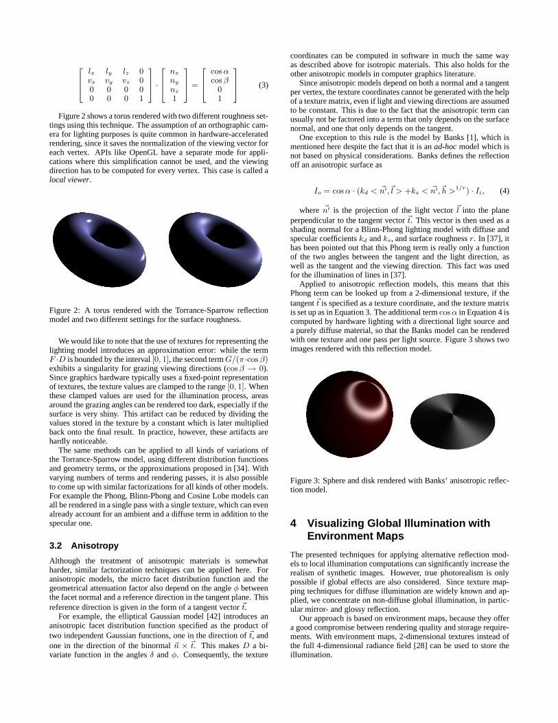
Figure 2 shows a torus rendered with two different roughness set-tings using this technique. The assumption of an orthographic cam-era for lighting purposes is quite common in hardware-acceleratedrendering, since it saves the normalization of the viewing vector foreach vertex. APIs like OpenGL have a separate mode for appli-cations where this simplification cannot be used, and the viewingdirection has to be computed for every vertex. This case is called alocal viewer.
Figure 2: A torus rendered with the Torrance-Sparrow reflectionmodel and two different settings for the surface roughness.
We would like to note that the use of textures for representing thelighting model introduces an approximation error: while the termF ·D is bounded by the interval [0, 1], the second term G/(π·cos β)exhibits a singularity for grazing viewing directions (cos β → 0).Since graphics hardware typically uses a fixed-point representationof textures, the texture values are clamped to the range [0, 1]. Whenthese clamped values are used for the illumination process, areasaround the grazing angles can be rendered too dark, especially if thesurface is very shiny. This artifact can be reduced by dividing thevalues stored in the texture by a constant which is later multipliedback onto the final result. In practice, however, these artifacts arehardly noticeable.
The same methods can be applied to all kinds of variations ofthe Torrance-Sparrow model, using different distribution functionsand geometry terms, or the approximations proposed in [34]. Withvarying numbers of terms and rendering passes, it is also possibleto come up with similar factorizations for all kinds of other models.For example the Phong, Blinn-Phong and Cosine Lobe models canall be rendered in a single pass with a single texture, which can evenalready account for an ambient and a diffuse term in addition to thespecular one.
3.2 Anisotropy
Although the treatment of anisotropic materials is somewhatharder, similar factorization techniques can be applied here. Foranisotropic models, the micro facet distribution function and thegeometrical attenuation factor also depend on the angle φ betweenthe facet normal and a reference direction in the tangent plane. Thisreference direction is given in the form of a tangent vector ~t.
For example, the elliptical Gaussian model [42] introduces ananisotropic facet distribution function specified as the product oftwo independent Gaussian functions, one in the direction of ~t, andone in the direction of the binormal ~n × ~t. This makes D a bi-variate function in the angles δ and φ. Consequently, the texture
coordinates can be computed in software in much the same wayas described above for isotropic materials. This also holds for theother anisotropic models in computer graphics literature.
Since anisotropic models depend on both a normal and a tangentper vertex, the texture coordinates cannot be generated with the helpof a texture matrix, even if light and viewing directions are assumedto be constant. This is due to the fact that the anisotropic term canusually not be factored into a term that only depends on the surfacenormal, and one that only depends on the tangent.
One exception to this rule is the model by Banks [1], which ismentioned here despite the fact that it is an ad-hoc model which isnot based on physical considerations. Banks defines the reflectionoff an anisotropic surface as
Io = cos α · (kd < ~n′,~l > +ks < ~n′,~h >1/r) · Ii, (4)
where ~n′ is the projection of the light vector ~l into the planeperpendicular to the tangent vector ~t. This vector is then used as ashading normal for a Blinn-Phong lighting model with diffuse andspecular coefficients kd and ks, and surface roughness r. In [37], ithas been pointed out that this Phong term is really only a functionof the two angles between the tangent and the light direction, aswell as the tangent and the viewing direction. This fact was usedfor the illumination of lines in [37].
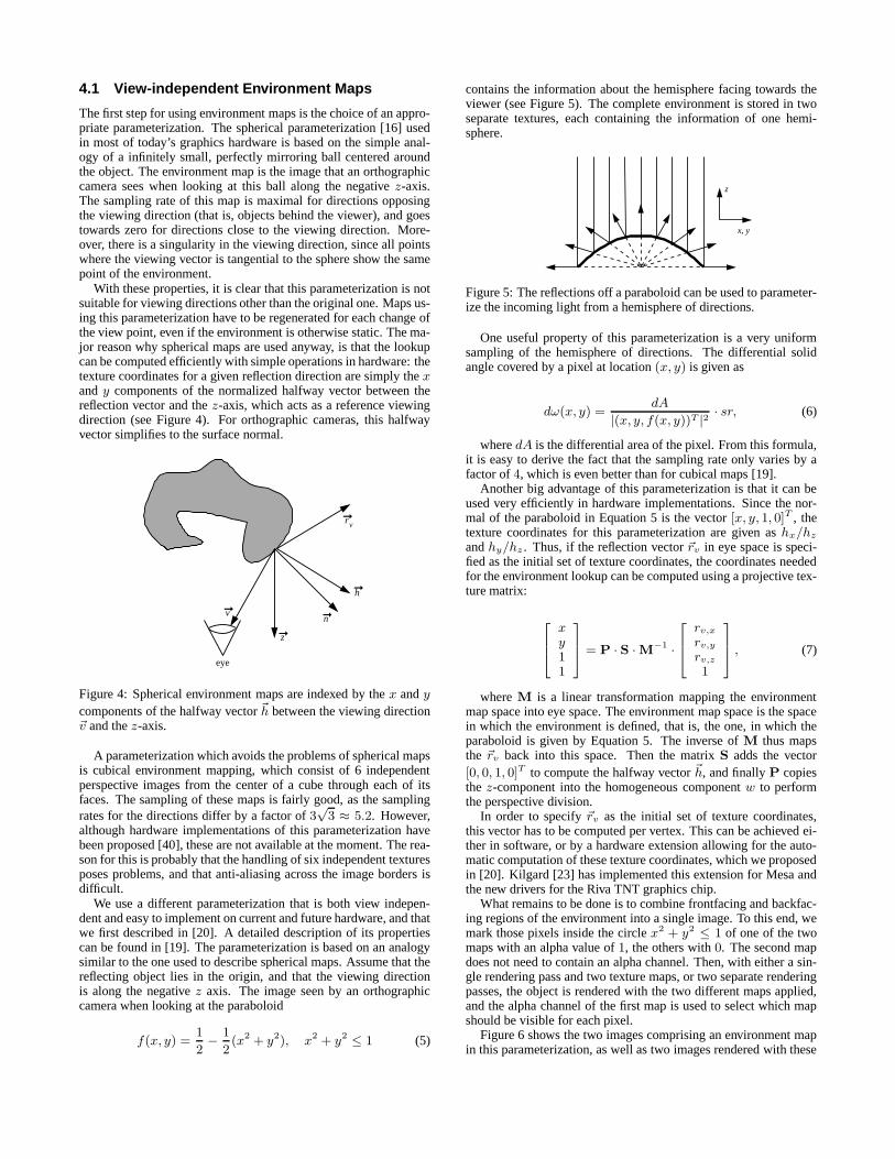
Applied to anisotropic reflection models, this means that thisPhong term can be looked up from a 2-dimensional texture, if thetangent ~t is specified as a texture coordinate, and the texture matrixis set up as in Equation 3. The additional term cos α in Equation 4 iscomputed by hardware lighting with a directional light source anda purely diffuse material, so that the Banks model can be renderedwith one texture and one pass per light source. Figure 3 shows twoimages rendered with this reflection model.
Figure 3: Sphere and disk rendered with Banks’ anisotropic reflec-tion model.
4 Visualizing Global Illumination withEnvironment Maps
The presented techniques for applying alternative reflection mod-els to local illumination computations can significantly increase therealism of synthetic images. However, true photorealism is onlypossible if global effects are also considered. Since texture map-ping techniques for diffuse illumination are widely known and ap-plied, we concentrate on non-diffuse global illumination, in partic-ular mirror- and glossy reflection.
Our approach is based on environment maps, because they offera good compromise between rendering quality and storage require-ments. With environment maps, 2-dimensional textures instead ofthe full 4-dimensional radiance field [28] can be used to store theillumination.
4.1 View-independent Environment Maps
The first step for using environment maps is the choice of an appro-priate parameterization. The spherical parameterization [16] usedin most of today’s graphics hardware is based on the simple anal-ogy of a infinitely small, perfectly mirroring ball centered aroundthe object. The environment map is the image that an orthographiccamera sees when looking at this ball along the negative z-axis.The sampling rate of this map is maximal for directions opposingthe viewing direction (that is, objects behind the viewer), and goestowards zero for directions close to the viewing direction. More-over, there is a singularity in the viewing direction, since all pointswhere the viewing vector is tangential to the sphere show the samepoint of the environment.
With these properties, it is clear that this parameterization is notsuitable for viewing directions other than the original one. Maps us-ing this parameterization have to be regenerated for each change ofthe view point, even if the environment is otherwise static. The ma-jor reason why spherical maps are used anyway, is that the lookupcan be computed efficiently with simple operations in hardware: thetexture coordinates for a given reflection direction are simply the xand y components of the normalized halfway vector between thereflection vector and the z-axis, which acts as a reference viewingdirection (see Figure 4). For orthographic cameras, this halfwayvector simplifies to the surface normal.
v
eye
z
h
rv
n
Figure 4: Spherical environment maps are indexed by the x and y
components of the halfway vector ~h between the viewing direction~v and the z-axis.
A parameterization which avoids the problems of spherical mapsis cubical environment mapping, which consist of 6 independentperspective images from the center of a cube through each of itsfaces. The sampling of these maps is fairly good, as the samplingrates for the directions differ by a factor of 3
√3 ≈ 5.2. However,
although hardware implementations of this parameterization havebeen proposed [40], these are not available at the moment. The rea-son for this is probably that the handling of six independent texturesposes problems, and that anti-aliasing across the image borders isdifficult.
We use a different parameterization that is both view indepen-dent and easy to implement on current and future hardware, and thatwe first described in [20]. A detailed description of its propertiescan be found in [19]. The parameterization is based on an analogysimilar to the one used to describe spherical maps. Assume that thereflecting object lies in the origin, and that the viewing directionis along the negative z axis. The image seen by an orthographiccamera when looking at the paraboloid
f(x, y) =1
2− 1
2(x2 + y2), x2 + y2 ≤ 1 (5)
contains the information about the hemisphere facing towards theviewer (see Figure 5). The complete environment is stored in twoseparate textures, each containing the information of one hemi-sphere.
z
x, y
Figure 5: The reflections off a paraboloid can be used to parameter-ize the incoming light from a hemisphere of directions.
One useful property of this parameterization is a very uniformsampling of the hemisphere of directions. The differential solidangle covered by a pixel at location (x, y) is given as
dω(x, y) =dA
|(x, y, f(x, y))T |2 · sr, (6)
where dA is the differential area of the pixel. From this formula,it is easy to derive the fact that the sampling rate only varies by afactor of 4, which is even better than for cubical maps [19].
Another big advantage of this parameterization is that it can beused very efficiently in hardware implementations. Since the nor-mal of the paraboloid in Equation 5 is the vector [x, y, 1, 0]T , thetexture coordinates for this parameterization are given as hx/hz
and hy/hz . Thus, if the reflection vector ~rv in eye space is speci-fied as the initial set of texture coordinates, the coordinates neededfor the environment lookup can be computed using a projective tex-ture matrix:
xy11
= P · S ·M−1 ·
rv,x
rv,y
rv,z
1
, (7)
where M is a linear transformation mapping the environmentmap space into eye space. The environment map space is the spacein which the environment is defined, that is, the one, in which theparaboloid is given by Equation 5. The inverse of M thus mapsthe ~rv back into this space. Then the matrix S adds the vector[0, 0, 1, 0]T to compute the halfway vector ~h, and finally P copiesthe z-component into the homogeneous component w to performthe perspective division.
In order to specify ~rv as the initial set of texture coordinates,this vector has to be computed per vertex. This can be achieved ei-ther in software, or by a hardware extension allowing for the auto-matic computation of these texture coordinates, which we proposedin [20]. Kilgard [23] has implemented this extension for Mesa andthe new drivers for the Riva TNT graphics chip.
What remains to be done is to combine frontfacing and backfac-ing regions of the environment into a single image. To this end, wemark those pixels inside the circle x2 + y2 ≤ 1 of one of the twomaps with an alpha value of 1, the others with 0. The second mapdoes not need to contain an alpha channel. Then, with either a sin-gle rendering pass and two texture maps, or two separate renderingpasses, the object is rendered with the two different maps applied,and the alpha channel of the first map is used to select which mapshould be visible for each pixel.
Figure 6 shows the two images comprising an environment mapin this parameterization, as well as two images rendered with these
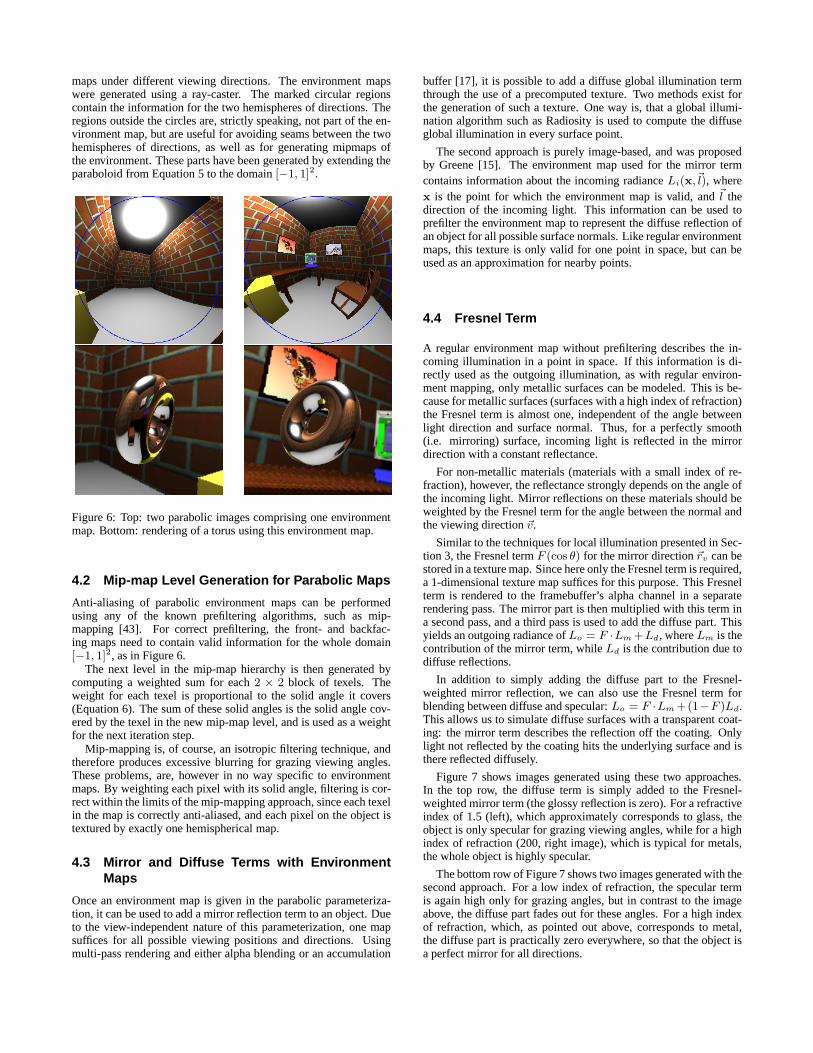
maps under different viewing directions. The environment mapswere generated using a ray-caster. The marked circular regionscontain the information for the two hemispheres of directions. Theregions outside the circles are, strictly speaking, not part of the en-vironment map, but are useful for avoiding seams between the twohemispheres of directions, as well as for generating mipmaps ofthe environment. These parts have been generated by extending theparaboloid from Equation 5 to the domain [−1, 1]2.
Figure 6: Top: two parabolic images comprising one environmentmap. Bottom: rendering of a torus using this environment map.
4.2 Mip-map Level Generation for Parabolic Maps
Anti-aliasing of parabolic environment maps can be performedusing any of the known prefiltering algorithms, such as mip-mapping [43]. For correct prefiltering, the front- and backfac-ing maps need to contain valid information for the whole domain[−1, 1]2, as in Figure 6.
The next level in the mip-map hierarchy is then generated bycomputing a weighted sum for each 2 × 2 block of texels. Theweight for each texel is proportional to the solid angle it covers(Equation 6). The sum of these solid angles is the solid angle cov-ered by the texel in the new mip-map level, and is used as a weightfor the next iteration step.
Mip-mapping is, of course, an isotropic filtering technique, andtherefore produces excessive blurring for grazing viewing angles.These problems, are, however in no way specific to environmentmaps. By weighting each pixel with its solid angle, filtering is cor-rect within the limits of the mip-mapping approach, since each texelin the map is correctly anti-aliased, and each pixel on the object istextured by exactly one hemispherical map.
4.3 Mirror and Diffuse Terms with EnvironmentMaps
Once an environment map is given in the parabolic parameteriza-tion, it can be used to add a mirror reflection term to an object. Dueto the view-independent nature of this parameterization, one mapsuffices for all possible viewing positions and directions. Usingmulti-pass rendering and either alpha blending or an accumulation
buffer [17], it is possible to add a diffuse global illumination termthrough the use of a precomputed texture. Two methods exist forthe generation of such a texture. One way is, that a global illumi-nation algorithm such as Radiosity is used to compute the diffuseglobal illumination in every surface point.
The second approach is purely image-based, and was proposedby Greene [15]. The environment map used for the mirror termcontains information about the incoming radiance Li(x,~l), wherex is the point for which the environment map is valid, and ~l thedirection of the incoming light. This information can be used toprefilter the environment map to represent the diffuse reflection ofan object for all possible surface normals. Like regular environmentmaps, this texture is only valid for one point in space, but can beused as an approximation for nearby points.
4.4 Fresnel Term
A regular environment map without prefiltering describes the in-coming illumination in a point in space. If this information is di-rectly used as the outgoing illumination, as with regular environ-ment mapping, only metallic surfaces can be modeled. This is be-cause for metallic surfaces (surfaces with a high index of refraction)the Fresnel term is almost one, independent of the angle betweenlight direction and surface normal. Thus, for a perfectly smooth(i.e. mirroring) surface, incoming light is reflected in the mirrordirection with a constant reflectance.
For non-metallic materials (materials with a small index of re-fraction), however, the reflectance strongly depends on the angle ofthe incoming light. Mirror reflections on these materials should beweighted by the Fresnel term for the angle between the normal andthe viewing direction ~v.
Similar to the techniques for local illumination presented in Sec-tion 3, the Fresnel term F (cos θ) for the mirror direction ~rv can bestored in a texture map. Since here only the Fresnel term is required,a 1-dimensional texture map suffices for this purpose. This Fresnelterm is rendered to the framebuffer’s alpha channel in a separaterendering pass. The mirror part is then multiplied with this term ina second pass, and a third pass is used to add the diffuse part. Thisyields an outgoing radiance of Lo = F ·Lm +Ld, where Lm is thecontribution of the mirror term, while Ld is the contribution due todiffuse reflections.
In addition to simply adding the diffuse part to the Fresnel-weighted mirror reflection, we can also use the Fresnel term forblending between diffuse and specular: Lo = F ·Lm +(1−F )Ld.This allows us to simulate diffuse surfaces with a transparent coat-ing: the mirror term describes the reflection off the coating. Onlylight not reflected by the coating hits the underlying surface and isthere reflected diffusely.
Figure 7 shows images generated using these two approaches.In the top row, the diffuse term is simply added to the Fresnel-weighted mirror term (the glossy reflection is zero). For a refractiveindex of 1.5 (left), which approximately corresponds to glass, theobject is only specular for grazing viewing angles, while for a highindex of refraction (200, right image), which is typical for metals,the whole object is highly specular.
The bottom row of Figure 7 shows two images generated with thesecond approach. For a low index of refraction, the specular termis again high only for grazing angles, but in contrast to the imageabove, the diffuse part fades out for these angles. For a high indexof refraction, which, as pointed out above, corresponds to metal,the diffuse part is practically zero everywhere, so that the object isa perfect mirror for all directions.
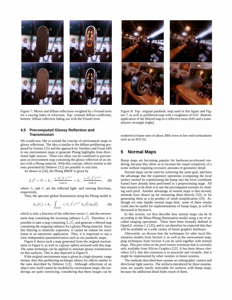
Figure 7: Mirror and diffuse reflections weighted by a Fresnel termfor a varying index of refraction. Top: constant diffuse coefficient,bottom: diffuse reflection fading out with the Fresnel term.
4.5 Precomputed Glossy Reflection andTransmission
We would now like to extend the concept of environment maps toglossy reflections. The idea is similar to the diffuse prefiltering pro-posed by Greene [15] and the approach by Voorhies and Foran [40]to use environment maps to generate Phong highlights from direc-tional light sources. These two ideas can be combined to precom-pute an environment map containing the glossy reflection of an ob-ject with a Phong material. With this concept, effects similar to theones presented by Debevec [12] are possible in real time.
As shown in [24], the Phong BRDF is given by
fr(~l → ~v) = ks · < ~rl, ~v >1/r
cos α= ks · < ~rv,~l >1/r
cos α, (8)
where ~rl, and ~rv are the reflected light- and viewing directions,respectively.
Thus, the specular global illumination using the Phong model is
Lo(~rv) = ks ·∫
Ω(~n)
< ~rv,~l >1/r Li(~l) dω(~l), (9)
which is only a function of the reflection vector ~rv and the environ-ment map containing the incoming radiance Li(~l). Therefore, it ispossible to take a map containing Li(~l), and generate a filtered mapcontaining the outgoing radiance for a glossy Phong material. Sincethis filtering is relatively expensive, it cannot be redone for everyframe in an interactive application. Thus, it is important to use aview-independent parameterization such as our parabolic maps.
Figure 8 shows such a map generated from the original environ-ment in Figure 6, as well as a glossy sphere textured with this map.The same technique can be applied to simulate glossy transmissionon thin surfaces. This is also depicted in Figure 8.
If the original environment map is given in a high-dynamic rangeformat, then this prefiltering technique allows for effects similar tothe ones described by Debevec [12]. Although reflections of anobject onto itself cannot be modeled by environment maps, the ren-derings are quite convincing, considering that these images can be
Figure 8: Top: original parabolic map used in this figure and Fig-ure 7, as well as prefiltered map with a roughness of 0.01. Bottom:application of the filtered map to a reflective torus (left) and a trans-missive rectangle (right).
rendered at frame rates of about 20Hz even on low end workstationssuch as an SGI O2.
5 Normal Maps
Bump maps are becoming popular for hardware-accelerated ren-dering, because they allow us to increase the visual complexity of ascene without requiring excessive amounts of geometric detail.
Normal maps can be used for achieving the same goal, and havethe advantage that the expensive operations (computing the localsurface normal by transforming the bump into the local coordinateframe) have already been performed in a preprocessing stage. Allthat remains to be done is to use the precomputed normals for shad-ing each pixel. Another advantage of normal maps is that recentlymethods have shown up for measuring them directly [33], or forgenerating them as a by-product of mesh simplification [10]. Al-though we only handle normal maps here, some of these resultscould also be useful for implementations of bump maps, as will bediscussed in Section 6.
In this section, we first describe how normal maps can be litaccording to the Blinn-Phong illumination model using a set of so-called imaging operations. These have been formally defined inOpenGL version 1.2 [35], and it can therefore be expected that theywill be available on a wide variety of future graphics hardware.
Afterwards, we discuss how the techniques for other local illu-mination models from Section 3, as well as the environment map-ping techniques from Section 4 can be used together with normalmaps. This part relies on the pixel texture extension that is currentlyonly available from Silicon Graphics [22]. It has been shown else-where [21], that this extension is so powerful and versatile, that itmight be implemented by other vendors in future systems.
The methods described here assume an orthographic camera anddirectional light sources. The artifacts introduced by these assump-tions are usually barely noticeable for surfaces with bump maps,because the additional detail hides much of them.

5.1 Normal Maps with local Blinn-Phong Illumina-tion
Among many other features (see [35] for details), the imaging op-erations make it possible to apply a 4× 4 matrix to each pixel in animage, as it is transferred to or from the frame buffer or to textureRAM. Following this color matrix transformation, a lookup tablemay be applied to each individual color component.
With these two mechanisms and a given normal map in the formof a color coded image, the map can be lit in two rendering passes.First, a color matrix is specified, which maps the normal from ob-ject space into eye space and then computes the diffuse illumination(which is essentially given by the dot product with the light direc-tion). When the normal image is now loaded into texture RAM,the lighting computations are performed. Afterwards the loaded, littexture is applied to the object using texture mapping.
A similar second rendering pass draws the specular part. Thistime, however, the matrix computes the dot product between normaland the halfway vector~h from Figure 1. The exponentiation by 1/r,where r is the surface roughness, is performed by a color lookuptable.
Figure 9 shows two images where one polygon is rendered withthis technique. On the left side, a simple exponential wave functionis used as a normal map. The normal map for the image on theright side has been measured from a piece of wallpaper with theapproach presented in [33].
Figure 9: Two Phong-lit normal maps. The right one has beenmeasured from a piece of wallpaper using the approach presentedin [33].
5.2 Normal Maps with Other Reflection Modelsand Environment Maps
The techniques from Sections 3 and 4 could also be applied to nor-mal maps, if the texture lookup could be performed per pixel insteadof only per vertex. This can be achieved using the pixel texture ex-tension from Silicon Graphics. It adds an additional stage to therendering pipeline directly after the color matrix and the color tabledescribed above. This stage allows to interpret each of the colorcomponents as a texture coordinate pointing into a 1-, 2-, 3-, or4-dimensional texture (see [22] for details).
This leads to the following algorithm for applying alternativelighting models:
• Render the object with the color coded normal map as a tex-ture, thereby marking each visible pixel in the stencil buffer.
• Copy the frame buffer to main memory. This yields an imagewhich contains the normal vector for each pixel.
• For each pass described in Section 3, set up the color matrixand blending as required by the respective illumination model,
and copy the normal image from main memory into the framebuffer. Copy only those pixels marked in the stencil buffer.
For environment maps, the situation is somewhat more difficult,because the parabolic parameterization requires the use of projec-tive textures, which are currently not supported by the pixel textureextension. As has been pointed out in [21], this limitation also pre-vents the use of pixel textures in other interesting applications, suchas shadow maps. Hopefully this restriction will be removed in thefuture. Until then, pixel textures can still be used for environmentmapping from a fixed viewing direction, which of course defeatsthe point of introducing the parabolic parameterization.
The images in Figure 10 were generated using the pixel textureextension and a single, view-dependent environment map.
Figure 10: Combination of environment mapping and normal map-ping. Left: environment map only. Right: Local Phong illumina-tion plus environment map.
6 Discussion and Conclusions
The methods described in this paper provide means for generatingrealistic shading and lighting effects with computer graphics hard-ware. We have concentrated on concepts that can be implementedon current graphics hardware. All the techniques presented hererun at frame rates of 15-20Hz on an SGI O2 (except for the onesrequiring pixel textures, which the O2 does not support), and > 20Hz on an SGI Octane MXE.
To conclude, we would now like to mention some issues whichwe deem important for the design of future graphics hardware:
The number of required rendering passes is reduced dramaticallyif the hardware has support for multiple textures. This is a featurewhich is beginning to appear on PC boards, and will probably beuniversally available soon.
Pixel textures are a very valuable tool and should be availableon more platforms (see [21] for other applications than presentedhere). They should also support projective textures.
The easiest way to directly support our techniques in future hard-ware is to add more automatic texture generation modes. For localillumination with isotropic lighting models, the cosines betweensurface normal, facet normal, light direction and viewing directionare required. Except for orthographic viewing and directional lightsources, these angles need to be computed in software, which re-quires the transformation of all vectors into eye space. For hard-ware lighting, these vectors are available in eye space anyway, so ifthe hardware could generate these cosine values automatically, thiswould both improve the performance and simplify the implemen-tation. Automatic texture coordinate generation is also useful forgenerating the reflection vector required for the parabolic environ-ment map parameterization. As pointed out above, this extension isalready available in some implementations of OpenGL [23].
A more ambitious change to the rendering pipeline would be toreplace the traditional hardware Phong lighting with a customiz-able sampling-based approach. In this case, the programmer wouldspecify the material as a set of two or three 2-dimensional tablesthat can be downloaded to the hardware. The geometry processinghardware can then compute the indices into these tables for multiplelight sources at the same time.
Although we have only discussed normal maps, the shading andlighting techniques presented here could also be applied to bumpmapping hardware, by allowing an additional texture access afterthe normal for a pixel has been computed. This would, in particu-lar, be a transparent implementation of environment maps for bumpmapping hardware.
7 Acknowledgments
This work was done while the authors worked at the Universityof Erlangen. The cafe environment map used in this paper is aresampled version of the spherical map used in [16]. We would liketo thank Mark Kilgard for implementing the extension for parabolicenvironment maps for Mesa and Riva TNT.
References[1] D. C. Banks. Illumination in diverse codimensions. In Computer Graphics (Pro-
ceedings of SIGGRAPH ’94), pages 327–334, July 1994.
[2] R. Bastos, K. Hoff, W. Wynn, and A. Lastra. Increased photorealism for inter-active architectural walkthroughs. In Symposium on Interactive 3D Graphics.ACM Siggraph, 1999.
[3] P. Beckmann and A. Spizzichino. The Scattering of Electromagnetic Waves fromRough Surfaces. McMillan, 1963.
[4] J. F. Blinn. Models of light reflection for computer synthesized pictures. InComputer Graphics (SIGGRAPH ’77 Proceedings), pages 192–198, July 1977.
[5] J. F. Blinn. Simulation of wrinkled surfaces. In Computer Graphics (SIGGRAPH’78 Proceedings), pages 286–292, August 1978.
[6] J. F. Blinn and M. E. Newell. Texture and reflection in computer generatedimages. Communications of the ACM, 19:542–546, 1976.
[7] P. Bui-Tuong. Illumination for computer generated pictures. Communications ofthe ACM, 18(6):311–317, June 1975.
[8] B. Cabral, N. Max, and R. Springmeyer. Bidirectional reflection functions fromsurface bump maps. In Computer Graphics (SIGGRAPH ’87 Proceedings),pages 273–281, July 1987.
[9] B. Cabral, M. Olano, and P. Nemec. Reflection space image based rendering. InComputer Graphics (SIGGRAPH ’99 Proceedings), August 1999.
[10] J. Cohen, M. Olano, and D. Manocha. Appearance-preserving simplification. InComputer Graphics (SIGGRAPH ’98 Proceedings), pages 115–122, July 1998.
[11] R. L. Cook and K. E. Torrance. A reflectance model for computer graphics.In Computer Graphics (SIGGRAPH ’81 Proceedings), pages 307–316, August1981.
[12] P. Debevec. Rendering synthetic objects into real scenes: Bridging traditionaland image-based graphics with global illumination and high dynamic range pho-tography. In Computer Graphics (SIGGRAPH ’98 Proceedings), pages 189–198,July 1998.
[13] P. J. Diefenbach. Pipeline Rendering: Interaction and Realism ThroughHardware-based Multi-Pass Rendering. PhD thesis, University of Pennsylva-nia, 1996.
[14] I. Ernst, H. Russeler, H. Schulz, and O. Wittig. Gouraud bump mapping. In Eu-rographics/SIGGRAPH Workshop on Graphics Hardware, pages 47–54, 1998.
[15] N. Greene. Applications of world projections. In Proceedings of Graphics Inter-face ’86, pages 108–114, May 1986.
[16] P. Haeberli and M. Segal. Texture mapping as A fundamental drawing primitive.In Fourth Eurographics Workshop on Rendering, pages 259–266, June 1993.
[17] P. E. Haeberli and K. Akeley. The accumulation buffer: Hardware support forhigh-quality rendering. In Computer Graphics (SIGGRAPH ’90 Proceedings),pages 309–318, August 1990.
[18] X. D. He, K. E. Torrance, F. X. Sillion, and D. P. Greenberg. A comprehen-sive physical model for light reflection. In Computer Graphics (SIGGRAPH ’91Proceedings), pages 175–186, July 1991.
[19] W. Heidrich. High-quality Shading and Lighting for Hardware-accelerated Ren-dering. PhD thesis, University of Erlangen-Nurnberg, April 1999.
[20] W. Heidrich and H.-P. Seidel. View-independent environment maps. In Euro-graphics/SIGGRAPH Workshop on Graphics Hardware, pages 39–45, 1998.
[21] W. Heidrich, R. Westermann, H.-P. Seidel, and Th. Ertl. Applications of pixeltextures in visualization and realistic image synthesis. In Symposium on Interac-tive 3D Graphics, 1999. (Accepted for publication).
[22] Silicon Graphics Inc. Pixel Texture Extension, December 1996. Specificationdocument, available from http://www.opengl.org.
[23] M. Kilgard. Personal communication, April 1999.
[24] R. R. Lewis. Making shaders more physically plausible. In Fourth EurographicsWorkshop on Rendering, pages 47–62, June 1993.
[25] T. McReynolds, D. Blythe, B. Grantham, and S. Nelson. Advanced graphicsprogramming techniques using OpenGL. In Siggraph 1998 Course Notes, July1998.
[26] G. Miller, M. Halstead, and M. Clifton. On-the-fly texture computation for real-time surface shading. IEEE Computer Graphics & Applications, 18(2):44–58,March–April 1998.
[27] G. Miller and C. Hoffman. Illumination and reflection maps: Simulated objectsin simulated and real environments. In ACM SIGGRAPH ’84 Course Notes -Advanced Computer Graphics Animation, July 1984.
[28] G. Miller, S. Rubin, and D. Ponceleon. Lazy decompression of surface lightfields for precomputed global illumnation. In Rendering Techniques ’98 (Pro-ceedings of Eurographics Rendering Workshop), pages 281–292, March 1998.
[29] E. Ofek and A. Rappoport. Interactive reflections on curved objects. In ComputerGraphics (SIGGRAPH ’98 Proceedings), pages 333–342, July 1998.
[30] M. Olano and A. Lastra. A shading language on graphics hardware: The Pix-elFlow shading system. In Computer Graphics (SIGGRAPH ’98 Proceedings),pages 159–168, July 1998.
[31] M. Peercy, J. Airey, and B. Cabral. Efficient bump mapping hardware. In Com-puter Graphics (SIGGRAPH ’97 Proceedings), pages 303–306, August 1997.
[32] P. Poulin and A. Fournier. A model for anisotropic reflection. In ComputerGraphics (SIGGRAPH ’90 Proceedings), volume 24, pages 273–282, August1990.
[33] H. Rushmeier, G. Taubin, and A. Gueziec. Applying shape from lighting varia-tion to bump map capture. In Rendering Techniques ’97 (Proceedings of Euro-graphics Rendering Workshop), pages 35–44, June 1997.
[34] C. Schlick. A customizable reflectance model for everyday rendering. In FourthEurographics Workshop on Rendering, pages 73–83, June 1993.
[35] M. Segal and K. Akeley. The OpenGL Graphics System: A Specification (Version1.2), 1998.
[36] B. G. Smith. Geometrical shadowing of a random rough surface. IEEE Transac-tions on Antennas and Propagation, 15(5):668–671, September 1967.
[37] D. Stalling, M. Zockler, and H.-C. Hege. Fast display of illuminated fieldlines. IEEE Transactions on Visualization and Computer Graphics, 3(2):118–128, 1997.
[38] W. Sturzlinger and R. Bastos. Interactive rendering of globally illuminatedglossy scenes. In Rendering Techniques ’97, pages 93–102, 1997.
[39] K. E. Torrance and E. M. Sparrow. Theory for off-specular reflection from rough-ened surfaces. Journal of the Optical Society of America, 57(9):1105–1114,September 1967.
[40] D. Voorhies and J. Foran. Reflection vector shading hardware. In ComputerGraphics (SIGGRAPH ’94 Proceedings), pages 163–166, July 1994.
[41] B. Walter, G. Alppay, E. Lafortune, S. Fernandez, and D. P. Greenberg. Fittingvirtual lights for non-diffuse walkthroughs. Computer Graphics (SIGGRAPH’97 Proceedings), pages 45–48, August 1997.
[42] G. J. Ward. Measuring and modeling anisotropic reflection. Computer Graphics(SIGGRAPH ’92 Proceedings), pages 265–273, July 1992.
[43] L. Williams. Pyramidal parametrics. In Computer Graphics (SIGGRAPH ’83Proceedings), pages 1–11, July 1983.