Real-Time Systems III Lecture3.pdf · First production car using CAN ... Automotive Electronics...
34
Real-Time Systems III Alan Burns University of York, UK
Transcript of Real-Time Systems III Lecture3.pdf · First production car using CAN ... Automotive Electronics...
Real-Time Systems III
Alan BurnsUniversity of York, UK
2
Hot Topics
Multiprocessor systemsMulti-resource schedulingSoc & NoCProbabilistic analysisHierarchical schedulingNon-preemptive and safety-critical system
Controller Area Network (CAN) Schedulability Analysis:
Refuted, Revisited and Revised
Research by:Robert Davis, Alan Burns (University of York)
Reinder Bril, Johan Lukkien (Technische Universiteit Eindhoven)
Published – Real-Time Systems Journal, Vol 35, No 3, pp 239--272 2007
4
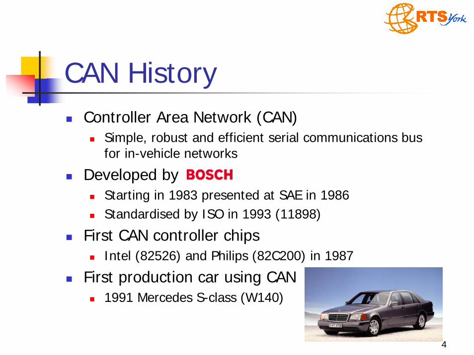
CAN HistoryController Area Network (CAN)
Simple, robust and efficient serial communications bus for in-vehicle networks
Developed by Starting in 1983 presented at SAE in 1986Standardised by ISO in 1993 (11898)
First CAN controller chipsIntel (82526) and Philips (82C200) in 1987
First production car using CAN1991 Mercedes S-class (W140)
5
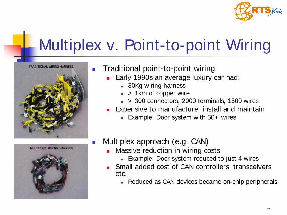
Multiplex v. Point-to-point WiringTraditional point-to-point wiring
Early 1990s an average luxury car had:30Kg wiring harness> 1km of copper wire> 300 connectors, 2000 terminals, 1500 wires
Expensive to manufacture, install and maintainExample: Door system with 50+ wires
Multiplex approach (e.g. CAN)Massive reduction in wiring costs
Example: Door system reduced to just 4 wiresSmall added cost of CAN controllers, transceivers etc.
Reduced as CAN devices became on-chip peripherals
6
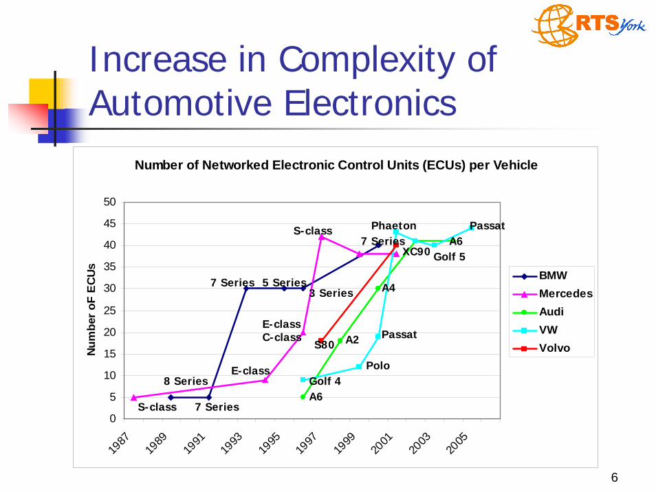
Number of Networked Electronic Control Units (ECUs) per Vehicle
0
5
10
15
20
25
30
35
40
45
50
1987
1989
1991
1993
1995
1997
1999
2001
2003
2005
Num
ber o
F E
CU
s
BMWMercedesAudiVWVolvo
Increase in Complexity of Automotive Electronics
S-class 7 Series
7 Series 5 Series
S-class Phaeton Passat
Golf 4
Golf 5A6
Passat
Polo
A4
A2
A6
3 Series
7 Series
E-class
E-classC-class
8 Series
S80
XC90
7
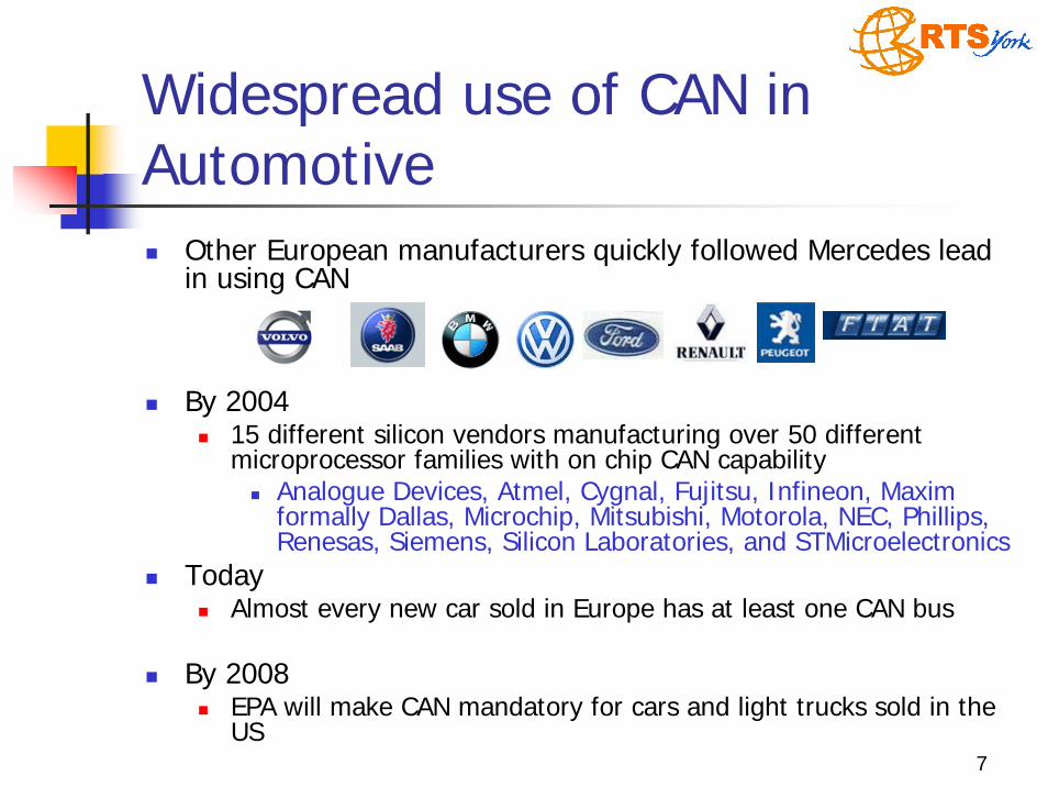
Widespread use of CAN in Automotive
Other European manufacturers quickly followed Mercedes lead in using CAN
By 200415 different silicon vendors manufacturing over 50 different microprocessor families with on chip CAN capability
Analogue Devices, Atmel, Cygnal, Fujitsu, Infineon, Maxim formally Dallas, Microchip, Mitsubishi, Motorola, NEC, Phillips,Renesas, Siemens, Silicon Laboratories, and STMicroelectronics
TodayAlmost every new car sold in Europe has at least one CAN bus
By 2008EPA will make CAN mandatory for cars and light trucks sold in the US
8
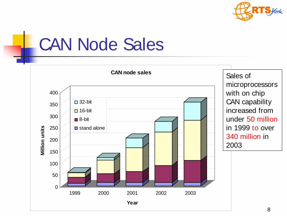
CAN Node Sales
0
50
100
150
200
250
300
350
400
Mill
ion
units
1999 2000 2001 2002 2003
Year
CAN node sales
32-bit
16-bit
8-bit
stand alone
Sales of microprocessors with on chip CAN capability increased from under 50 millionin 1999 to over 340 million in 2003

9
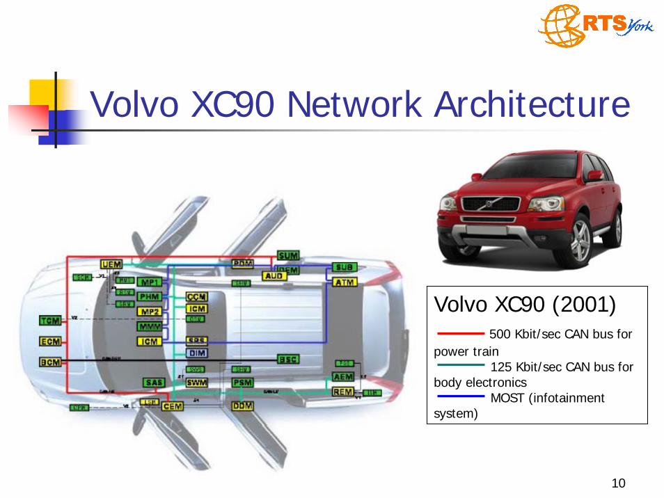
CAN in AutomotiveCAN typically used to provide
“High speed” (500 Kbit/sec) network connecting chassis and power train ECUs
E.g. transmission control, engine management, ABS etc.Low speed (100-125 Kbit/sec) network(s) connecting body and comfort electronics
E.g. door modules, seat modules, climate control etc.Data required by ECUs on different networks
typically “gatewayed” between them via a powerful microprocessor connected to both
10
Volvo XC90 Network Architecture
Volvo XC90 (2001)500 Kbit/sec CAN bus for
power train125 Kbit/sec CAN bus for
body electronicsMOST (infotainment
system)
11
Information on CANCAN used to communicate signals between ECUs
Signals typically range from 1 to 16-bits of informationwheel speeds, oil and water temperature, battery voltage, engine rpm, gear selection, accelerator position, dashboard switch positions, climate control settings, window switch positions, fault codes, diagnostic information etc.> 2,500 signals in a high-end vehicleMultiple signals piggybacked into CAN messages to reduce overhead
Real-time constraints on signal transmissionEnd-to-end deadlines in the range 10ms – 1secExample LED brake lights
12
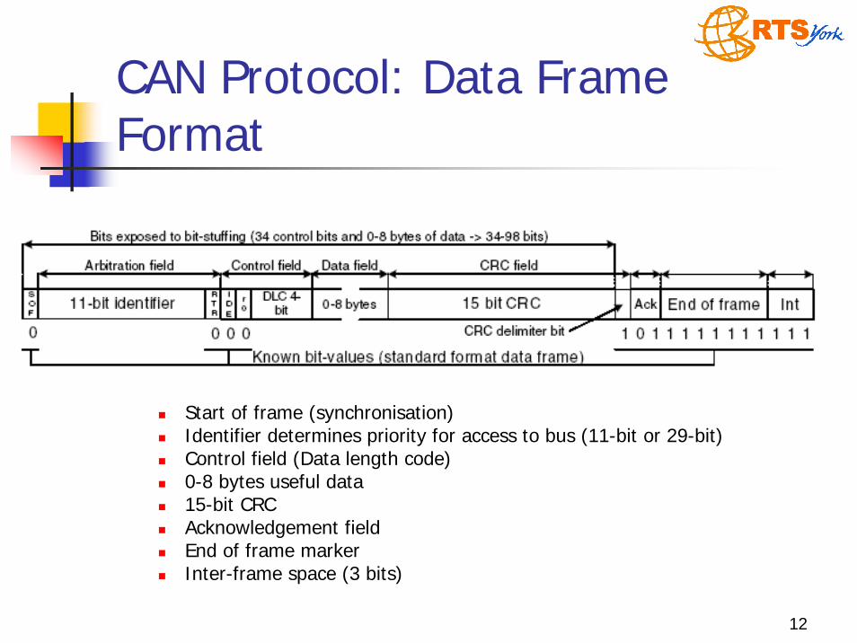
CAN Protocol: Data Frame Format
Start of frame (synchronisation)Identifier determines priority for access to bus (11-bit or 29-bit)Control field (Data length code)0-8 bytes useful data15-bit CRCAcknowledgement field End of frame markerInter-frame space (3 bits)

13
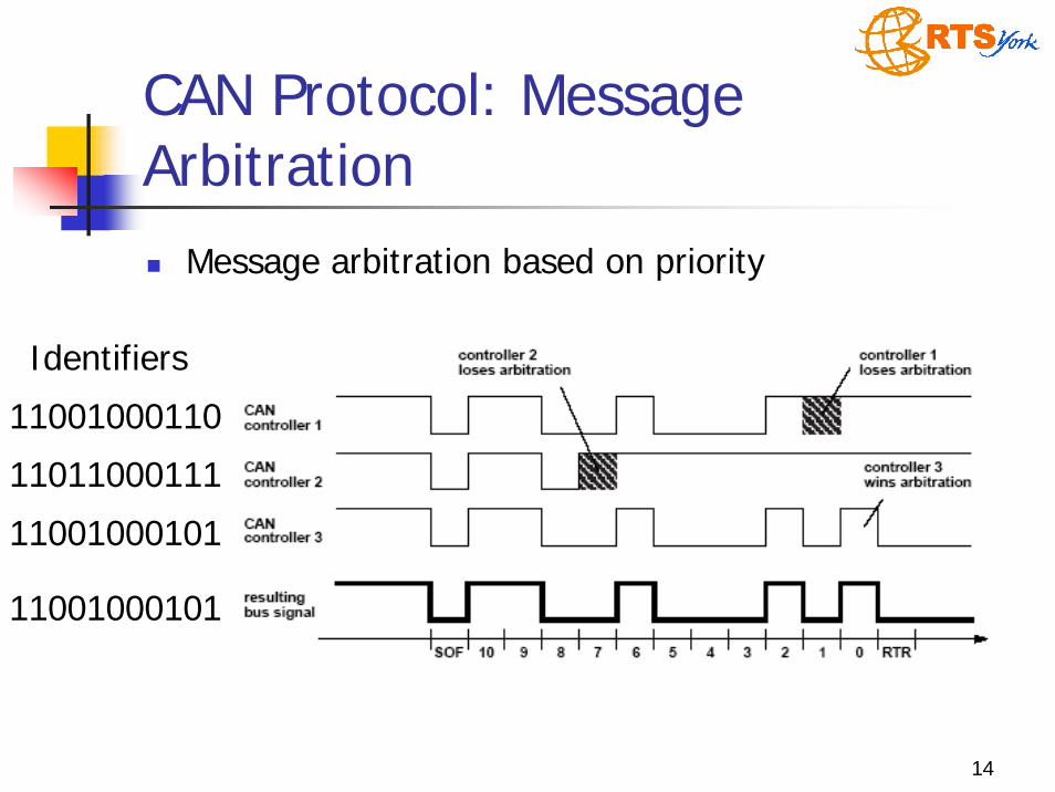
CAN ProtocolCAN is a multi-master CSMA/CR serial bus
Collision resolution is based on priorityCAN physical layer supports two states: “0” dominant, “1”recessive
Message transmissionCAN nodes wait for “bus idle” before starting transmissionSynchronise on the SOF bit (“0”)Each node starts to transmit the identifier for its highest priority (lowest identifier value) ready messageIf a node transmits “1” and sees “0” on the bus, then it stops transmitting (lost arbitration)Node that completes transmission of its identifier continues with remainder of its message (wins arbitration)Unique identifiers ensure all other nodes have backed off
14
CAN Protocol: Message Arbitration
Message arbitration based on priority
11001000110
11011000111
11001000101
Identifiers
11001000101
15
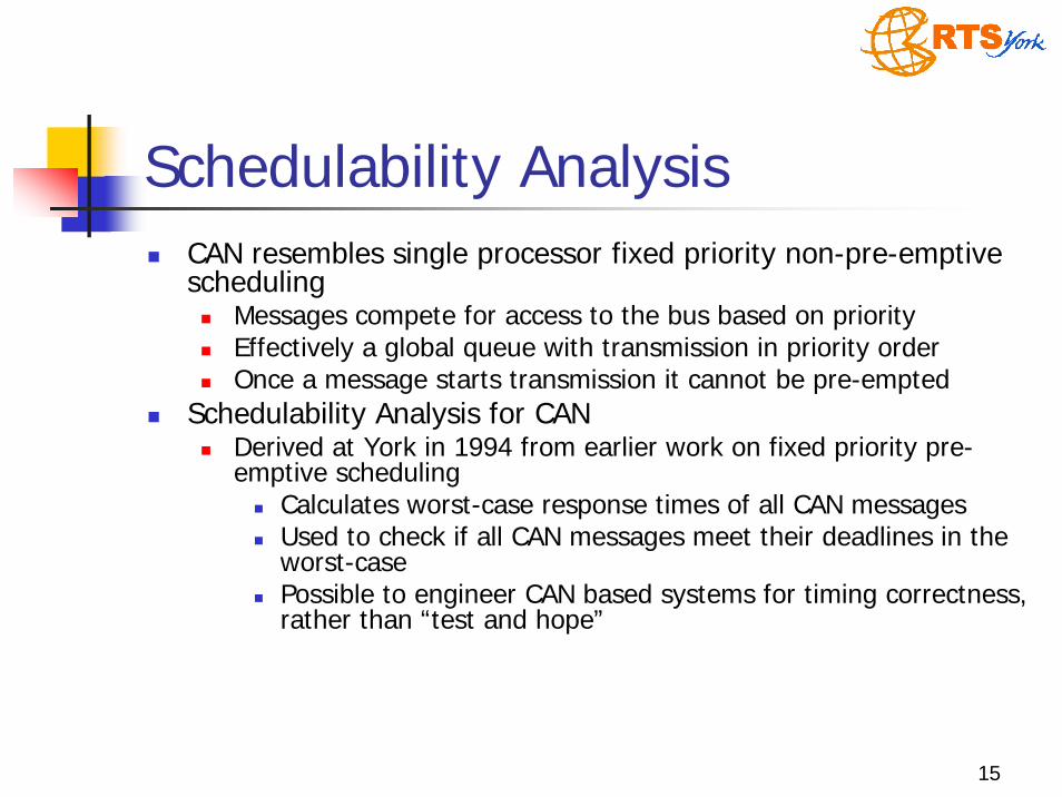
Schedulability AnalysisCAN resembles single processor fixed priority non-pre-emptive scheduling
Messages compete for access to the bus based on priorityEffectively a global queue with transmission in priority orderOnce a message starts transmission it cannot be pre-empted
Schedulability Analysis for CANDerived at York in 1994 from earlier work on fixed priority pre-emptive scheduling
Calculates worst-case response times of all CAN messagesUsed to check if all CAN messages meet their deadlines in the worst-case Possible to engineer CAN based systems for timing correctness, rather than “test and hope”

16
Schedulability AnalysisSchedulability analysis for CAN
Seminal research, appeared in conferenceproceedings, journal papers, tutorials etc.Referenced in over 200 subsequent research papersLead to 2 PhD Theses In 1995 recognised by Volvo Car CorporationUsed in the developmentof the Volvo S80 (P23)Enabled increases in networkutilisation from 30-40% to >80%Formed basis of commercial CAN analysis productsUsed by many Automotive manufacturers who have built millions of cars with networks analysed using these techniques
17
UnfortunatelyThe original schedulability analysis for CAN is seriously flawed…
18
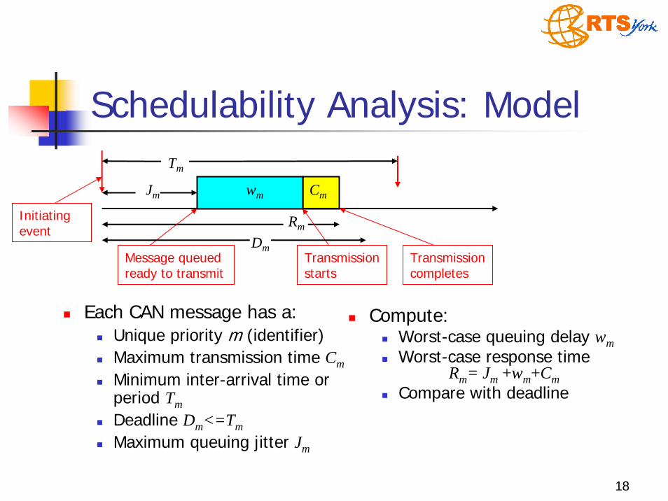
Schedulability Analysis: Model
Each CAN message has a:Unique priority m (identifier)Maximum transmission time CmMinimum inter-arrival time or period TmDeadline Dm<=TmMaximum queuing jitter Jm
Tm
Rm
Jm wm Cm
Initiating event
Transmission starts
Message queuedready to transmit
Transmission completes
Dm
Compute:Worst-case queuing delay wmWorst-case response time
Rm= Jm +wm+CmCompare with deadline

19
Schedulability Analysis: TX TimeMaximum transmission time
Bit stuffingBit patterns “000000” and “111111” used to signal errorsTransmitter insert 0s and 1s to avoid 6 consecutive bits of same polarity in messages
Increases transmission time of message
11-bit identifiers:
29-bit identifiers:
bitmm sC τ)1055( +=
bitmm sC τ)1080( +=
20
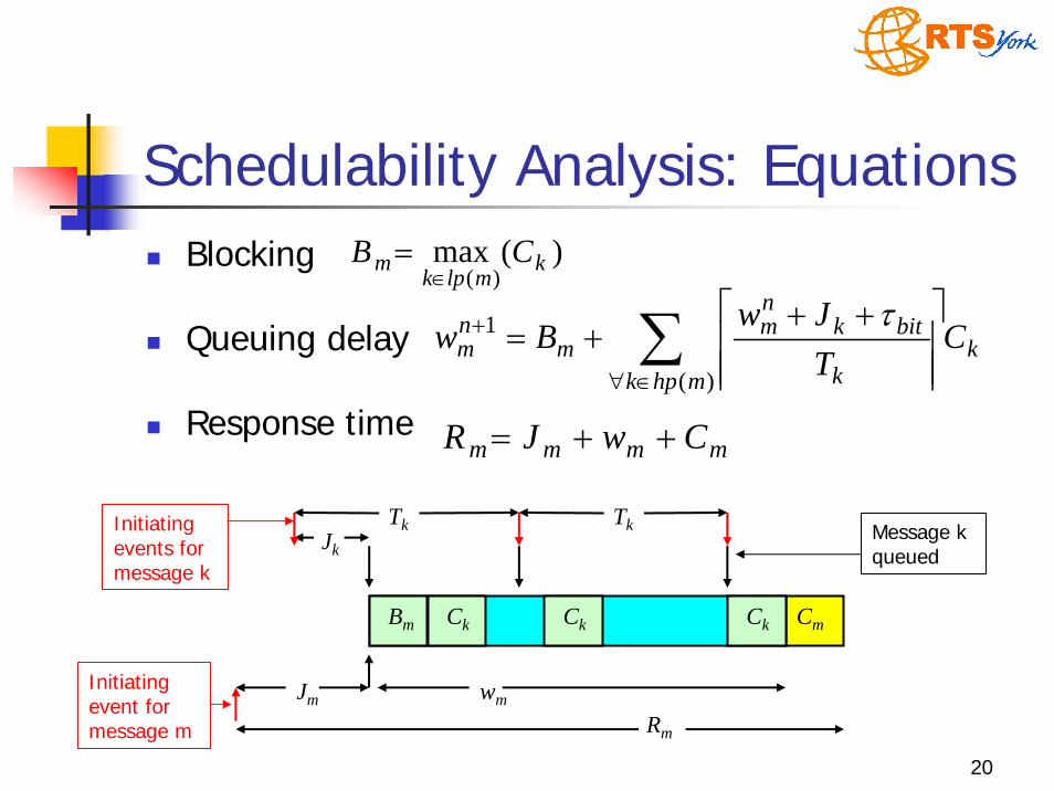
Schedulability Analysis: EquationsBlocking
Queuing delay
Response time
kmhpk k
bitknm
mnm C
TJw
Bw ∑∈∀
+
⎥⎥⎥
⎤
⎢⎢⎢
⎡ +++=
)(
1 τ
)(max)(
kmlpk
m CB∈
=
Tk
Rm
Jk
Ck
Initiating events for message k
wm
Tk
CmBm Ck Ck
Message k queued
JmInitiating event for message m
mmmm CwJR ++=
21
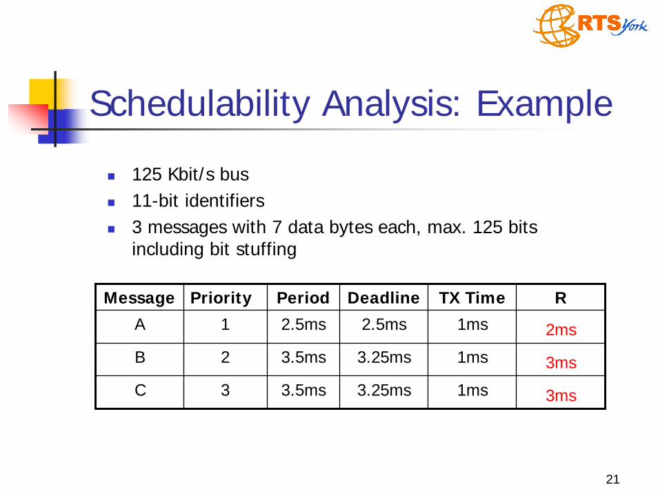
Schedulability Analysis: Example
125 Kbit/s bus11-bit identifiers3 messages with 7 data bytes each, max. 125 bits including bit stuffing
Message Priority Period Deadline TX Time R
A 2ms
3ms
3ms
B
C
1 2.5ms 2.5ms 1ms
2 3.5ms 3.25ms 1ms
3 3.5ms 3.25ms 1ms
22
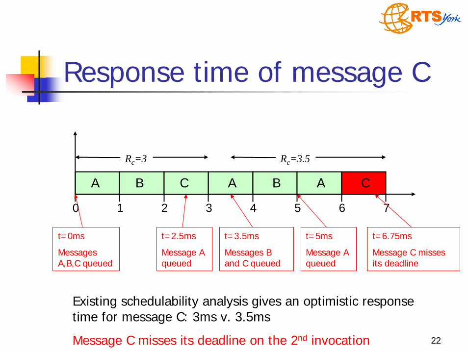
Response time of message C
t=3.5ms
Messages B and C queued
A
t=5ms
Message A queued
B A
t=0ms
Messages A,B,C queued
t=2.5ms
Message A queued
A B C
0 1 2 3
Rc=3
4 5 6 7
Existing schedulability analysis gives an optimistic response time for message C: 3ms v. 3.5ms
Message C misses its deadline on the 2nd invocation
C
Rc=3.5
t=6.75ms
Message C misses its deadline
23
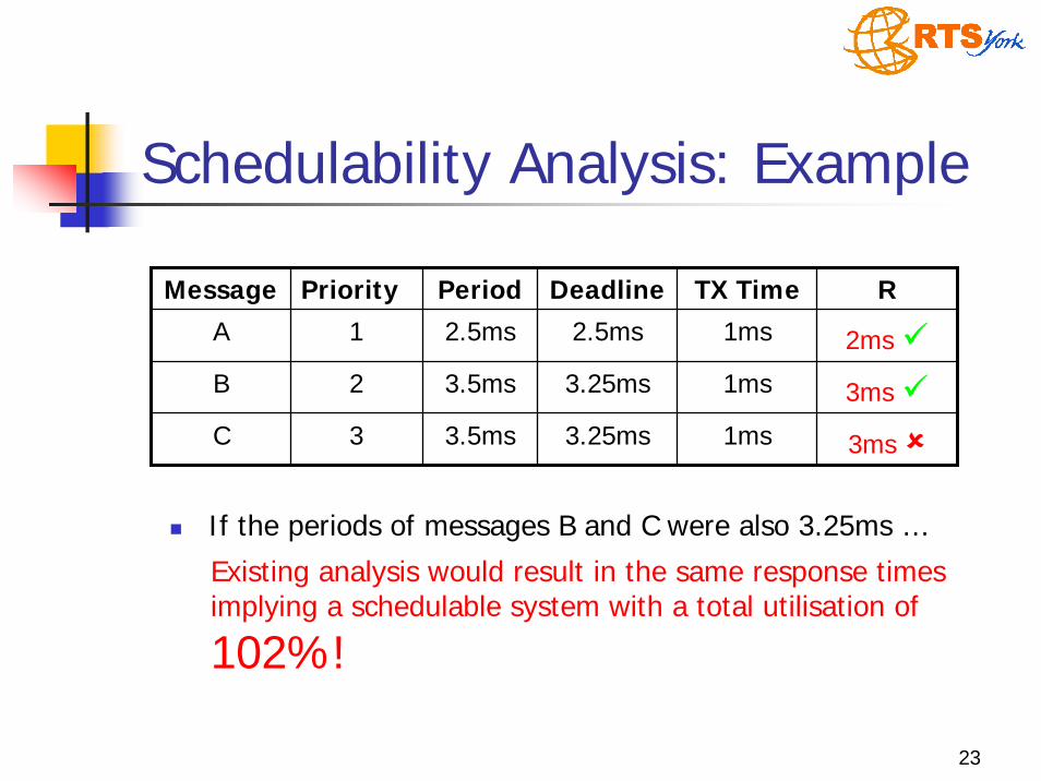
Schedulability Analysis: Example
If the periods of messages B and C were also 3.25ms …
Message Priority Period Deadline TX Time R
A 2ms
3ms
3ms
B
C
1 2.5ms 2.5ms 1ms
2 3.5ms 3.25ms 1ms
3 3.5ms 3.25ms 1ms
Existing analysis would result in the same response times implying a schedulable system with a total utilisation of
102%!
24
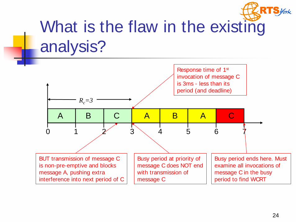
What is the flaw in the existing analysis?
A
BUT transmission of message C is non-pre-emptive and blocks message A, pushing extra interference into next period of C
Response time of 1st
invocation of message C is 3ms - less than its period (and deadline)
A B C
0 1 2 3
Rc=3
4 5 6 7
Busy period at priority of message C does NOT end with transmission of message C
B A C
Busy period ends here. Must examine all invocations of message C in the busy period to find WCRT
25
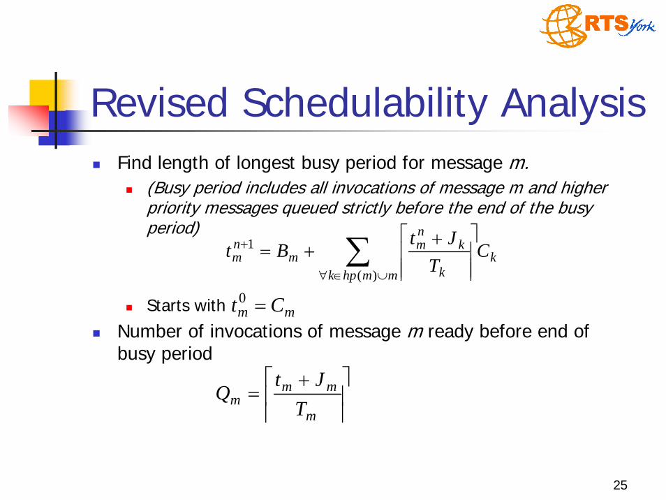
Revised Schedulability AnalysisFind length of longest busy period for message m.
(Busy period includes all invocations of message m and higher priority messages queued strictly before the end of the busy period)
Starts with
Number of invocations of message m ready before end of busy period
kmmhpk k
knm
mnm C
TJt
Bt ∑∪∈∀
+
⎥⎥⎥
⎤
⎢⎢⎢
⎡ ++=
)(
1
mm Ct =0
⎥⎥
⎤⎢⎢
⎡ +=
m
mmm T
JtQ

26
Revised Schedulability AnalysisFor each invocation q (q = 0 to Qm – 1) in the busy period, compute the longest time from the start of the busy period to that invocation of message m starting transmission:
Response time of invocation q of message m:
Worst-case response time of message m:
kmhpk k
bitknm
mmnm C
TJw
qCBqw ∑∈∀
+
⎥⎥⎥
⎤
⎢⎢⎢
⎡ ++++=
)(
1 )(τ
mmmmm CqTqwJqR +−+= )()(
))((max1..0
qRR mQq
mm−=
=
27
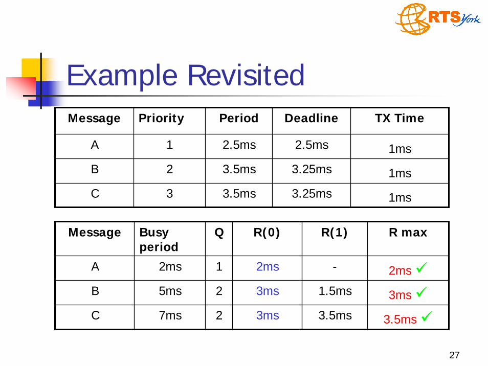
Example RevisitedMessage Priority Period Deadline TX Time
A
B
C
1 2.5ms 2.5ms 1ms
2 3.5ms 3.25ms 1ms
3 3.5ms 3.25ms 1ms
Message Busy period
Q R(0) R(1) R max
A 2ms
3ms
3.5ms
B
C
2ms 1 2ms -
5ms 2 3ms 1.5ms
7ms 2 3ms 3.5ms
28
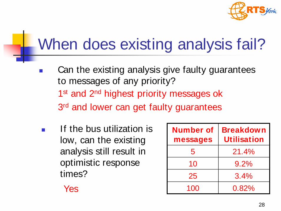
Can the existing analysis give faulty guarantees to messages of any priority?1st and 2nd highest priority messages ok3rd and lower can get faulty guarantees
Number of messages
Breakdown Utilisation
5 21.4%
10 9.2%
25 3.4%
100 0.82%
When does existing analysis fail?
If the bus utilization is low, can the existing analysis still result in optimistic response times?
Yes

29
Yes: If a system is deemed schedulable by the existing analysis, including a reasonable error model, then it is actually schedulable when there are no errors on the bus
When does existing analysis fail?Do error models give sufficient margin for error to account for flaws in the analysis?
Does the omission of maximum length diagnostic messages during normal operation mean that the deadlines of the remaining messages will be met?
Yes: other messages will meet their deadlines. In normal operation, with no diagnostic messages, there can be no problem due to the flawed analysis
30
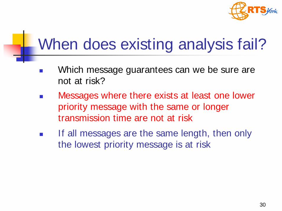
Which message guarantees can we be sure are not at risk?Messages where there exists at least one lower priority message with the same or longer transmission time are not at risk
When does existing analysis fail?
If all messages are the same length, then only the lowest priority message is at risk
31
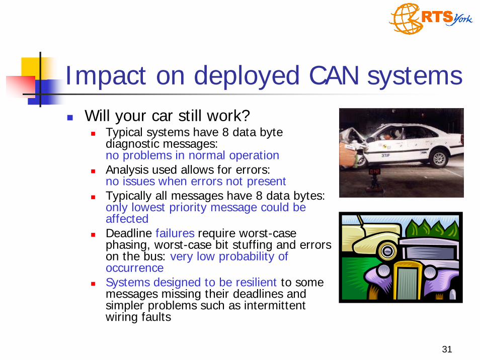
Impact on deployed CAN systemsWill your car still work?
Typical systems have 8 data byte diagnostic messages:no problems in normal operationAnalysis used allows for errors:no issues when errors not presentTypically all messages have 8 data bytes:only lowest priority message could be affectedDeadline failures require worst-case phasing, worst-case bit stuffing and errors on the bus: very low probability of occurrenceSystems designed to be resilient to some messages missing their deadlines and simpler problems such as intermittent wiring faults
32
Commercial CAN Analysis ToolsVolcano Network Architect
Commercial CAN schedulability analysis productfrom Volcano Communications TechnologiesUses a simple sufficient schedulability test, assuming maximum blocking factor irrespective of message priorities / number of data bytes
Pessimistic but correct upper bound on message worst-case response timesUsed to analyse CAN systems for Volvo S80, S/V/XC 70, S40, V50, XC90 and many other cars from other manufacturersOver 20 million cars with an average 20 ECUs each developed using Volcano technology
kmhpk k
bitknmMAXn
m CTJw
Bw ∑∈∀
+
⎥⎥⎥
⎤
⎢⎢⎢
⎡ +++=
)(
1 τ
33
Technical report and PaperTechnical Report
Controller Area Network (CAN) Schedulability analysis, refuted, revisited and revised Department of Computer Science Technical Report YCS-2006-408, University of York, August 2006
www.cs.york.ac.uk/ftpdir/reports/YCS-2006-408.pdf
Paper published in Journalof Real-Time Systems

34
Conclusions
Real-time systems are everywhereScheduling analysis is necessary to build these systemsFixed priority dispatching and response-time analysis (RTA) is a mature engineering approach, butErrors are still possible