Real-Time Spectrum Analyzers RSA3408A · Event-based Capture of Transient RF Signals by Triggering...
12
Features & Benefits Trigger – Tektronix Exclusive Frequency Mask Trigger Makes Easy Event-based Capture of Transient RF Signals by Triggering on Any Change in the Frequency Domain Capture – All Input Signals Up to 36 MHz *1 Spans Are Seamlessly Captured Into Memory – Long Record Length at 36 MHz Span Enables Complete Analysis Over Time Without Making Multiple Acquisitions – Interfaces With TekConnect ® Probes for RF and Baseband Probing Analyze – Gain a Unique Understanding of Time-varying RF Signals – See Frequency and Amplitude Change Over Time – Built-in 802.11a/b/g/n Measure- ment Suite – Comprehensive Pulsed Analysis Suite – High 3G Measurement Versatility with W-CDMA, cdma2000, 1X EVDO, HSUPA, HSDPA, TD-SCDMA RF and Modulation Analysis – Capture and Analyze on RFID Interrogator and Tag Response Signals – Signal Source Analysis Simplifies Phase Noise, Jitter and Frequency Settling Measurements – C4FM Modulation Analysis for Project 25 Compliance Measurements – Easy Multi Carrier ACLR Measurement Applications System Integration of WLAN, 3G and Other RF Systems Radar and Pulsed RF Signal Characterization RFID System Development and Troubleshooting Characterization of Interfering or Unknown Signals in Spectrum Monitoring and Surveillance Troubleshooting RF Components, Modules or Systems Getting Answers to Elusive EMI Diagnostic Problems General Purpose Phase Noise and Jitter Signal Analysis *1 40 MHz bandwidth at baseband. Real-Time Spectrum Analyzers RSA3408A Trigger, Capture, Analyze WLAN, Radar, 3G or Other Time-varying RF Signals Get Fast Resolution to Complex Problems with Enhanced Triggering, More Capture Bandwidth and Great New Analysis Tools See the frequency and amplitude of your RF signal change over time in a single view. With only a single acquisition, the RSA3408A Real-Time Spectrum Analyzer (RTSA) captures a continuous time record of changing RF events and enables time-correlated analysis in the Frequency, Time and Modulation domains. You get the functionality of a vector signal analyzer, a wide band spectrum analyzer, plus the unique trigger-capture-analyze capability of RTSA – in one transportable package.
Transcript of Real-Time Spectrum Analyzers RSA3408A · Event-based Capture of Transient RF Signals by Triggering...

Features & Benefits
Trigger – Tektronix Exclusive Frequency
Mask Trigger Makes EasyEvent-based Capture ofTransient RF Signals byTriggering on Any Change in the Frequency Domain
Capture – All Input Signals Up to 36 MHz*1
Spans Are Seamlessly CapturedInto Memory
– Long Record Length at 36 MHzSpan Enables Complete AnalysisOver Time Without MakingMultiple Acquisitions
– Interfaces With TekConnect®
Probes for RF and BasebandProbing
Analyze – Gain a Unique Understanding
of Time-varying RF Signals – See Frequency and Amplitude
Change Over Time – Built-in 802.11a/b/g/n Measure-
ment Suite– Comprehensive Pulsed
Analysis Suite – High 3G Measurement
Versatility with W-CDMA,cdma2000, 1X EVDO, HSUPA,HSDPA, TD-SCDMA RF andModulation Analysis
– Capture and Analyze on RFID Interrogator and TagResponse Signals
– Signal Source AnalysisSimplifies Phase Noise, Jitterand Frequency SettlingMeasurements
– C4FM Modulation Analysis for Project 25 ComplianceMeasurements
– Easy Multi Carrier ACLRMeasurement
Applications
System Integration of WLAN, 3G and Other RF Systems
Radar and Pulsed RF SignalCharacterization
RFID System Development and Troubleshooting
Characterization of Interfering orUnknown Signals in SpectrumMonitoring and Surveillance
Troubleshooting RF Components,Modules or Systems
Getting Answers to Elusive EMIDiagnostic Problems
General Purpose Phase Noiseand Jitter Signal Analysis
*1 40 MHz bandwidth at baseband.
Real-Time Spectrum AnalyzersRSA3408A
Trigger, Capture, Analyze WLAN, Radar, 3G or Other Time-varying RF Signals
Get Fast Resolution to ComplexProblems with Enhanced Triggering,More Capture Bandwidth and GreatNew Analysis Tools
See the frequency and amplitude ofyour RF signal change over time in asingle view. With only a single acquisition,the RSA3408A Real-Time SpectrumAnalyzer (RTSA) captures a continuous
time record of changing RF events and enables time-correlated analysis in the Frequency, Time and Modulationdomains. You get the functionality of a vector signal analyzer, a wide bandspectrum analyzer, plus the uniquetrigger-capture-analyze capability ofRTSA – in one transportable package.
Real-Time Spectrum AnalyzersRSA3408A
RSA3408A • www.tektronix.com/rsa2
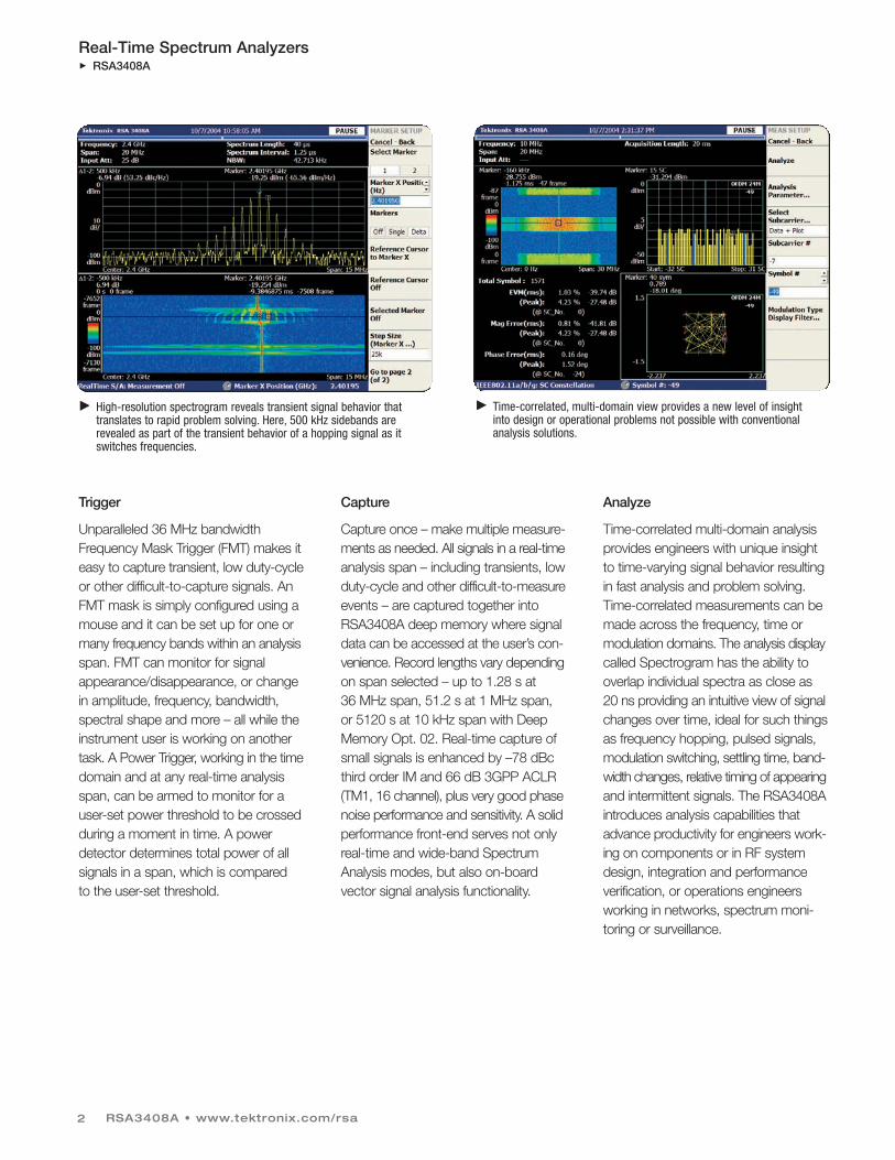
Trigger
Unparalleled 36 MHz bandwidthFrequency Mask Trigger (FMT) makes iteasy to capture transient, low duty-cycleor other difficult-to-capture signals. AnFMT mask is simply configured using amouse and it can be set up for one ormany frequency bands within an analysisspan. FMT can monitor for signalappearance/disappearance, or changein amplitude, frequency, bandwidth,spectral shape and more – all while theinstrument user is working on anothertask. A Power Trigger, working in the timedomain and at any real-time analysisspan, can be armed to monitor for auser-set power threshold to be crossedduring a moment in time. A powerdetector determines total power of allsignals in a span, which is compared to the user-set threshold.
Capture
Capture once – make multiple measure-ments as needed. All signals in a real-timeanalysis span – including transients, lowduty-cycle and other difficult-to-measureevents – are captured together intoRSA3408A deep memory where signaldata can be accessed at the user’s con-venience. Record lengths vary dependingon span selected – up to 1.28 s at36 MHz span, 51.2 s at 1 MHz span,or 5120 s at 10 kHz span with DeepMemory Opt. 02. Real-time capture ofsmall signals is enhanced by –78 dBcthird order IM and 66 dB 3GPP ACLR(TM1, 16 channel), plus very good phasenoise performance and sensitivity. A solidperformance front-end serves not onlyreal-time and wide-band SpectrumAnalysis modes, but also on-boardvector signal analysis functionality.
Analyze
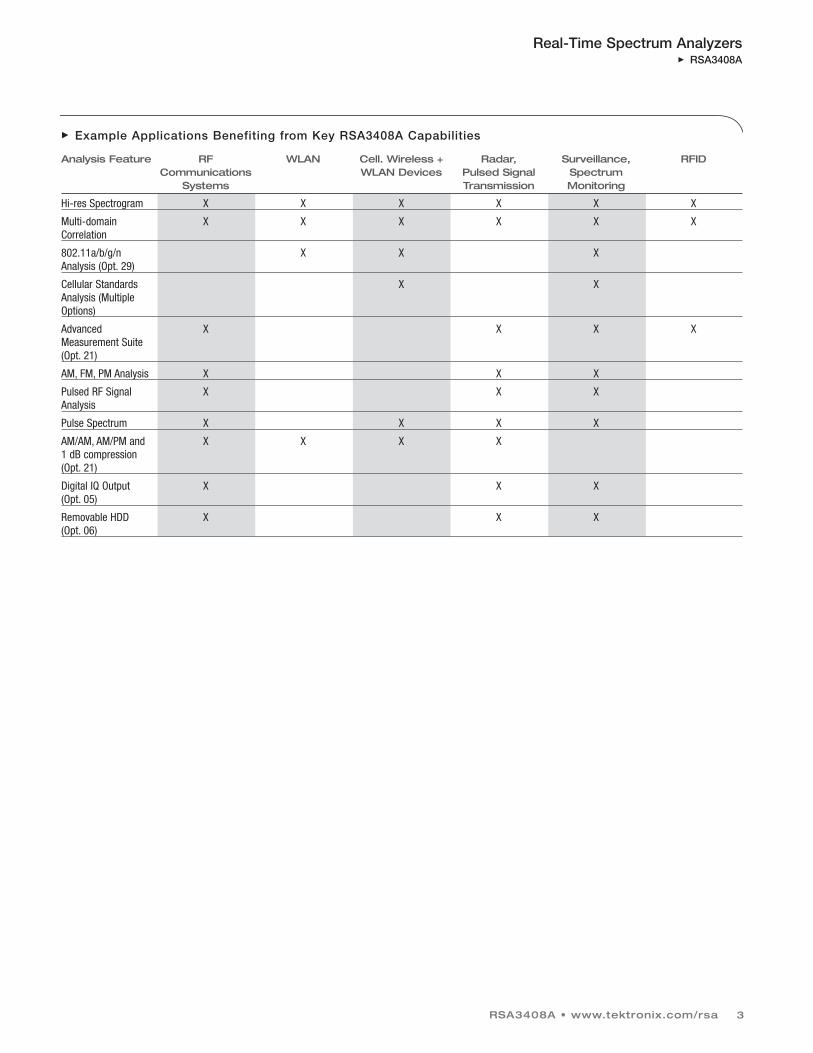
Time-correlated multi-domain analysisprovides engineers with unique insightto time-varying signal behavior resultingin fast analysis and problem solving.Time-correlated measurements can bemade across the frequency, time ormodulation domains. The analysis displaycalled Spectrogram has the ability tooverlap individual spectra as close as20 ns providing an intuitive view of signalchanges over time, ideal for such thingsas frequency hopping, pulsed signals,modulation switching, settling time, band-width changes, relative timing of appearingand intermittent signals. The RSA3408Aintroduces analysis capabilities thatadvance productivity for engineers work-ing on components or in RF systemdesign, integration and performanceverification, or operations engineersworking in networks, spectrum moni-toring or surveillance.
High-resolution spectrogram reveals transient signal behavior thattranslates to rapid problem solving. Here, 500 kHz sidebands arerevealed as part of the transient behavior of a hopping signal as itswitches frequencies.
Time-correlated, multi-domain view provides a new level of insight into design or operational problems not possible with conventionalanalysis solutions.
Real-Time Spectrum AnalyzersRSA3408A
RSA3408A • www.tektronix.com/rsa 3
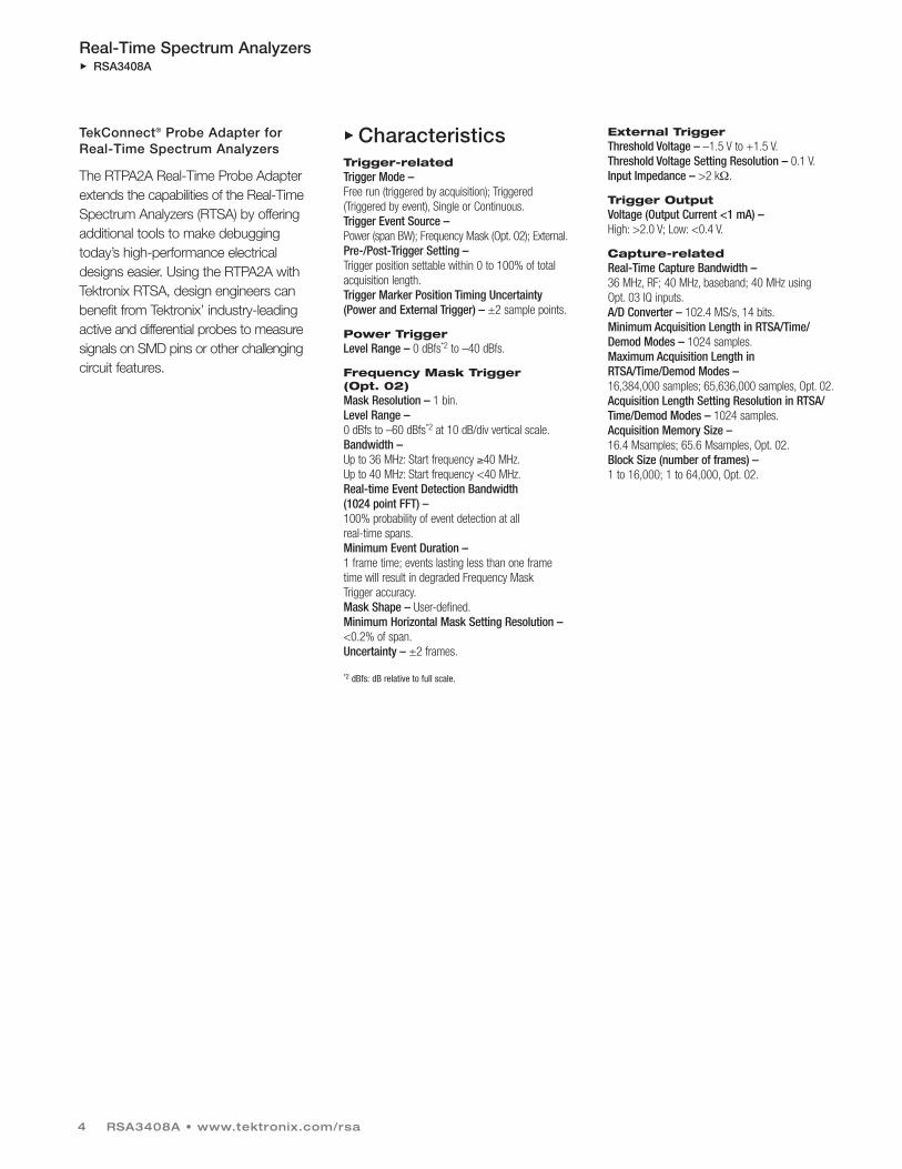
Example Applications Benefiting from Key RSA3408A Capabilities
Analysis Feature RF WLAN Cell. Wireless + Radar, Surveillance, RFIDCommunications WLAN Devices Pulsed Signal Spectrum
Systems Transmission Monitoring
Hi-res Spectrogram X X X X X X
Multi-domain X X X X X X Correlation
802.11a/b/g/n X X X Analysis (Opt. 29)
Cellular Standards X X Analysis (Multiple Options)
Advanced X X X X Measurement Suite (Opt. 21)
AM, FM, PM Analysis X X X
Pulsed RF Signal X X X Analysis
Pulse Spectrum X X X X
AM/AM, AM/PM and X X X X 1 dB compression (Opt. 21)
Digital IQ Output X X X (Opt. 05)
Removable HDD X X X (Opt. 06)
Real-Time Spectrum AnalyzersRSA3408A
TekConnect® Probe Adapter forReal-Time Spectrum Analyzers
The RTPA2A Real-Time Probe Adapterextends the capabilities of the Real-TimeSpectrum Analyzers (RTSA) by offeringadditional tools to make debuggingtoday’s high-performance electricaldesigns easier. Using the RTPA2A withTektronix RTSA, design engineers canbenefit from Tektronix’ industry-leadingactive and differential probes to measuresignals on SMD pins or other challengingcircuit features.
CharacteristicsTrigger-related Trigger Mode – Free run (triggered by acquisition); Triggered(Triggered by event), Single or Continuous.Trigger Event Source – Power (span BW); Frequency Mask (Opt. 02); External.Pre-/Post-Trigger Setting – Trigger position settable within 0 to 100% of totalacquisition length.Trigger Marker Position Timing Uncertainty(Power and External Trigger) – ±2 sample points.
Power Trigger Level Range – 0 dBfs*2 to –40 dBfs.
Frequency Mask Trigger (Opt. 02) Mask Resolution – 1 bin.Level Range – 0 dBfs to –60 dBfs*2 at 10 dB/div vertical scale.Bandwidth – Up to 36 MHz: Start frequency ≥40 MHz.Up to 40 MHz: Start frequency <40 MHz.Real-time Event Detection Bandwidth (1024 point FFT) – 100% probability of event detection at all real-time spans.Minimum Event Duration – 1 frame time; events lasting less than one frametime will result in degraded Frequency Mask Trigger accuracy.Mask Shape – User-defined.Minimum Horizontal Mask Setting Resolution – <0.2% of span.Uncertainty – ±2 frames.
*2 dBfs: dB relative to full scale.
External Trigger Threshold Voltage – –1.5 V to +1.5 V.Threshold Voltage Setting Resolution – 0.1 V.Input Impedance – >2 kΩ.
Trigger Output Voltage (Output Current <1 mA) – High: >2.0 V; Low: <0.4 V.
Capture-related Real-Time Capture Bandwidth – 36 MHz, RF; 40 MHz, baseband; 40 MHz using Opt. 03 IQ inputs.A/D Converter – 102.4 MS/s, 14 bits.Minimum Acquisition Length in RTSA/Time/Demod Modes – 1024 samples.Maximum Acquisition Length inRTSA/Time/Demod Modes – 16,384,000 samples; 65,636,000 samples, Opt. 02.Acquisition Length Setting Resolution in RTSA/Time/Demod Modes – 1024 samples.Acquisition Memory Size – 16.4 Msamples; 65.6 Msamples, Opt. 02.Block Size (number of frames) – 1 to 16,000; 1 to 64,000, Opt. 02.
RSA3408A • www.tektronix.com/rsa4
RSA3408A • www.tektronix.com/rsa 5
Real-Time Spectrum AnalyzersRSA3408A
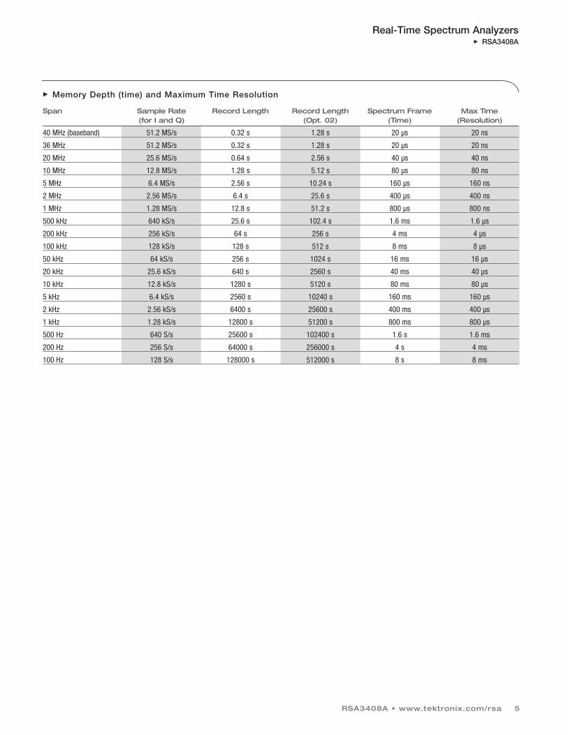
Memory Depth (time) and Maximum Time Resolution
Span Sample Rate Record Length Record Length Spectrum Frame Max Time(for I and Q) (Opt. 02) (Time) (Resolution)
40 MHz (baseband) 51.2 MS/s 0.32 s 1.28 s 20 µs 20 ns
36 MHz 51.2 MS/s 0.32 s 1.28 s 20 µs 20 ns
20 MHz 25.6 MS/s 0.64 s 2.56 s 40 µs 40 ns
10 MHz 12.8 MS/s 1.28 s 5.12 s 80 µs 80 ns
5 MHz 6.4 MS/s 2.56 s 10.24 s 160 µs 160 ns
2 MHz 2.56 MS/s 6.4 s 25.6 s 400 µs 400 ns
1 MHz 1.28 MS/s 12.8 s 51.2 s 800 µs 800 ns
500 kHz 640 kS/s 25.6 s 102.4 s 1.6 ms 1.6 µs
200 kHz 256 kS/s 64 s 256 s 4 ms 4 µs
100 kHz 128 kS/s 128 s 512 s 8 ms 8 µs
50 kHz 64 kS/s 256 s 1024 s 16 ms 16 µs
20 kHz 25.6 kS/s 640 s 2560 s 40 ms 40 µs
10 kHz 12.8 kS/s 1280 s 5120 s 80 ms 80 µs
5 kHz 6.4 kS/s 2560 s 10240 s 160 ms 160 µs
2 kHz 2.56 kS/s 6400 s 25600 s 400 ms 400 µs
1 kHz 1.28 kS/s 12800 s 51200 s 800 ms 800 µs
500 Hz 640 S/s 25600 s 102400 s 1.6 s 1.6 ms
200 Hz 256 S/s 64000 s 256000 s 4 s 4 ms
100 Hz 128 S/s 128000 s 512000 s 8 s 8 ms
Real-Time Spectrum AnalyzersRSA3408A
Analysis-related
RSA3408A • www.tektronix.com/rsa6
Measurement Functions by Mode
Mode Measurements
SA Channel Power, Adjacent Channel Power Ratio, Occupied Bandwidth,Emission Bandwidth, Carrier-to-Noise Ratio, Carrier Frequency,
Spur Search, db/Hz Marker, dBc/Hz Marker
RTSA Channel Power, Adjacent Channel Power Ratio, Occupied Bandwidth, Emission Bandwidth, Carrier-to-Noise Ratio, Carrier Frequency, Spur Search
Time IQ vs. Time, Power vs. Time, Frequency vs. Time, CCDF, Crest FactorPulse Measurements: Pulse Width, Pulse Peak Power, On/Off Ratio, Pulse
Ripple, Pulse Repetition Interval, Duty Cycle, Pulse-Pulse Phase,Channel Power, OBW, EBW, Frequency Deviation (Min. Pulse Length,20 samples; Max Pulse Length, 16,384 samples), Channel Power,
Frequency Deviation and EBW (less than 16,384 points)
Analog Demod IQ vs. Time, AM Depth, FM Deviation, PM Deviation, Pulse Spectrum
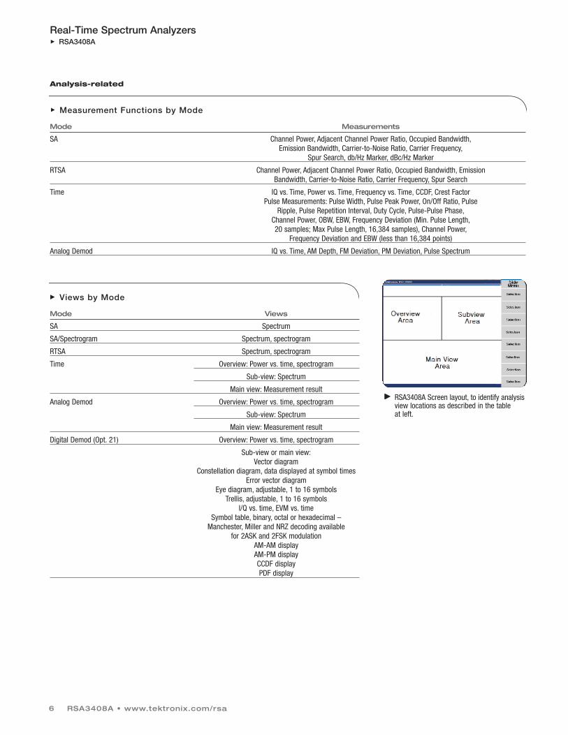
Views by Mode
Mode Views
SA Spectrum
SA/Spectrogram Spectrum, spectrogram
RTSA Spectrum, spectrogram
Time Overview: Power vs. time, spectrogram
Sub-view: Spectrum
Main view: Measurement result
Analog Demod Overview: Power vs. time, spectrogram
Sub-view: Spectrum
Main view: Measurement result
Digital Demod (Opt. 21) Overview: Power vs. time, spectrogram
Sub-view or main view:Vector diagram
Constellation diagram, data displayed at symbol timesError vector diagram
Eye diagram, adjustable, 1 to 16 symbolsTrellis, adjustable, 1 to 16 symbols
I/Q vs. time, EVM vs. timeSymbol table, binary, octal or hexadecimal –
Manchester, Miller and NRZ decoding available for 2ASK and 2FSK modulation
AM-AM displayAM-PM displayCCDF displayPDF display
RSA3408A Screen layout, to identify analysisview locations as described in the table at left.
RSA3408A • www.tektronix.com/rsa 7
Real-Time Spectrum AnalyzersRSA3408A
Measurement Speed Screen Update Rate – 2 MHz Span, AUTO RBW : 19.4/s.Remote Measurement Rate and GPIB TransferRate (2 MHz span, auto RBW, spectrum data) – 1.87 waveforms/s, or 6,000 S/s.RF Center Frequency Switching Time – <10 ms for 10 MHz frequency change; 500 ms for3 GHz frequency change.
Traces, Displays, Detectors Traces – Two traces, Spectrum Analyzer Mode.Displays – Up to three time-correlated, user-selected displays.Detector – RMS.Trace Types – Normal (RMS), Average, Max. Hold, Min. Hold.Display Detection – Max., Min., Max./Min.
Modulation Analysis Analog AMMinimum Input Level – –40 dBfs,*3 typical.PMMinimum Input Level – –40 dBfs, typical.PM Scale, Max, Min – ±180º.FMMinimum Input Level – –40 dBfs, typical.Range – ±Span/2 from center frequency.
*3 dBfs: dB relative to full scale.
C4FM (Fixed Symbol Rate) Digital (Opt. 21) Modulation Formats –BPSK, QPSK, π/4 DQPSK, OQPSK, 8PSK, 16QAM,32QAM, 64QAM, 128QAM, 256QAM, GMSK, GFSK,2ASK, 2FSK, C4FM.Analysis Period – Up to 81,408 sample points.Analysis Period for RFID Measurement –Up to capture length.Filter Types –Measurement filters: Square root raised cosine, none.Reference filters: Raised cosine, Gaussian, HalfSine,none.Alpha/B*T Range – 0.0001 to 1, 0.0001 step.
Demodulation Accuracy AnalogAM (–10 dBfs signal, input at CF, 10 to 60%modulation depth) – ±2%.PM (–10 dBfs signal, input at CF) – ±3º.FM (–10 dBfs signal, input at CF) – ±1% of span.
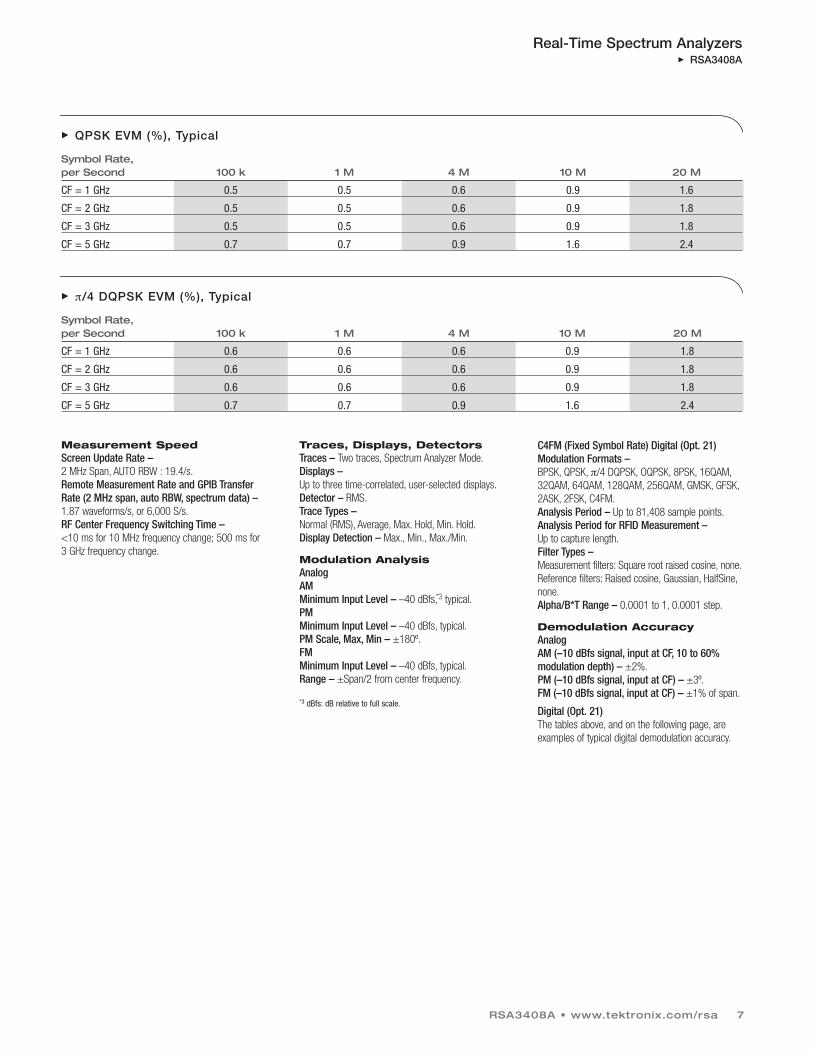
Digital (Opt. 21) The tables above, and on the following page, areexamples of typical digital demodulation accuracy.
QPSK EVM (%), Typical
Symbol Rate, per Second 100 k 1 M 4 M 10 M 20 M
CF = 1 GHz 0.5 0.5 0.6 0.9 1.6
CF = 2 GHz 0.5 0.5 0.6 0.9 1.8
CF = 3 GHz 0.5 0.5 0.6 0.9 1.8
CF = 5 GHz 0.7 0.7 0.9 1.6 2.4
π/4 DQPSK EVM (%), Typical
Symbol Rate, per Second 100 k 1 M 4 M 10 M 20 M
CF = 1 GHz 0.6 0.6 0.6 0.9 1.8
CF = 2 GHz 0.6 0.6 0.6 0.9 1.8
CF = 3 GHz 0.6 0.6 0.6 0.9 1.8
CF = 5 GHz 0.7 0.7 0.9 1.6 2.4

Real-Time Spectrum AnalyzersRSA3408A
RF Performance FREQUENCYFrequency Range – DC to 8 GHz.Center Frequency Setting Resolution – 0.1 Hz.Frequency Marker Readout Accuracy, Baseband –±(RE x MF + 0.001 x Span + 0.2) Hz.Frequency Marker Readout Accuracy, RF – ±(RE x MF + 0.001 x Span + 2) Hz.
RE: Reference Frequency Error.MF: Marker Frequency (Hz).
Span Accuracy – ±1 bin.RBW Filter Bandwidth Accuracy – 0.1%.Reference Frequency –
Aging per Day –1 x 10⁻⁹ (after 30 days of operation).Aging per Year – 1 x 10⁻⁷ (after 30 days of operation).Temperature Drift – 1 x 10⁻⁷ (10 to 40 ºC) Total Frequency Error –2 x 10⁻⁷ (within one year after calibration).Reference Output Level – >0 dBm.External Reference Input –10 MHz, –10 dBm to + 6 dBm.
Frequency Span – Range, Spectrum Analyzer Mode –
50 Hz to 3 GHz, (Start Frequency ≥40 MHz).0 Hz to 40 MHz, (Stop Frequency <40 MHz).
Range, Real-Time Spectrum Analyzer Mode –100 Hz to 20 MHz, 36 MHz (RF).0 Hz to 40 MHz, (Baseband).
IF Flatness – CF = 400 MHz.Frequency Bandwidth Flatness2 GHz ≤36.6 MHz ±0.3 dB 5 GHz ≤36.6 MHz ±0.3 dB
IF Phase Linearity – Frequency Bandwidth Flatness2 GHz ≤36.6 MHz ±2.5º 5 GHz ≤36.6 MHz ±2.5º
IF Filter Bandwidth – Resolution Bandwidth Range – 1 Hz to 10 MHz,automatically selected or user-defined.Accuracy – Within 6.0% ±0.1%.Shape Characteristic – Gaussian, <5:1 shapefactor (3:60 dB); Rectangular, Nyquist, Root Nyquistshapes may also be selected.
Minimum Settable RBW(Extended Resolution ON) Frequency RBW Span >2 GHz 100 kHz 1 GHz <Span ≤2 GHz 50 kHz 500 MHz <Span ≤1 GHz 20 kHz 20 MHz <Span ≤500 MHz 10 kHz 500 kHz <Span ≤20 MHz 1 kHz 200 kHz <Span ≤500 kHz 500 Hz 100 kHz <Span ≤200 kHz 200 Hz 50 kHz <Span ≤100 kHz 100 Hz 20 kHz <Span ≤50 kHz 50 Hz 10 kHz <Span ≤20 kHz 20 Hz 5 kHz <Span ≤10 kHz 10 Hz 2 kHz <Span ≤5 kHz 5 Hz 1 kHz <Span ≤2 kHz 2 Hz 100 Hz <Span ≤1 kHz 1 Hz
Noise Bandwidth Range, RTSA Mode –250.545 mHz to 100.218 kHz.FFT Performance – Number of Samples per Frame – 64 to 8192(65,536 samples per frame, extended resolution).Window Types – Rectangular, Parzen, Welch,Sine-Lobe, Hanning, Sine-cubed, Sine-To-The 4th,Hamming, Blackman, Rosenfield, Blackman-Harris3A, Blackman-Harris 3B, Blackman-Harris 4A,Blackman-Harris 4B, FlatTop.
RSA3408A • www.tektronix.com/rsa8
STABILITY
16/64 QAM EVM (%), Typical
Symbol Rate, per Second 100 k 1 M 4 M 10 M 20 M
CF = 1 GHz .5 .5 .5 .7 1.2
CF = 2 GHz .5 .5 .5 .7 1.2
CF = 3 GHz .5 .5 .5 .7 1.2
CF = 5 GHz .9 .5 .7 1.3 2
Noise Sidebands, dBc/Hz
Offset At 1 GHz CF At 2 GHz CF At 6 GHz CF
Spec Typical Spec Typical Spec Typical 1 kHz –105 –107 –103 –105 –97 –99 10 kHz –110 –112 –109 –111 –106 –108 20 kHz –110 –112 –109 –111 –106 –108 30 kHz –110 –112 –109 –111 –106 –108 100 kHz –112 –115 –112 –115 –111 –113 1 MHz –132 –135 –132 –135 –132 –134 5 MHz –138 –140 –138 –140 –137 –139 7 MHz –138 –140 –138 –140 –137 –139 10 MHz –138 –140 –138 –140 –137 –139

RSA3408A • www.tektronix.com/rsa 9
Real-Time Spectrum AnalyzersRSA3408A
Residual FM – 2 Hzpk-pk, typical.
AmplitudeMeasurement Range – Displayed average noise level to MAX safe input.Input Attenuator Range – RF/Baseband Input – 0 dB to 55 dB, 5 dB step.IQ Input (Opt. 03) – 0 dB to 35 dB, 5 dB step.Input Attenuator Setting Uncertainty (at100 MHz, 10 dB ATT, 20 ºC to 30 ºC) – ±0.2 dB.Maximum Safe Input Level – Average Continuous (RF band, RF ATT ≥10 dB) –+30 dB.MAX DC Voltage – ±0.2 V, RF; ±5 V, Baseband;±5 V, IQ input, Opt. 03.Log Display Range – 10 µdB/div to 10 dB/div.Linear Display Scale – 10 divisions.Linear Display Units – dBm, dBµV, V, Watts,Hz for FM Demod, Degrees for PM Demod.Marker Readout Resolution, Log – 0.01 dB.Marker Readout Resolution, Linear – 0.001 µV.
Absolute Amplitude Accuracy at CalibrationPoint (baseband, at 25 MHz, –10 dBm signal,0 dB ATT, 20 ºC to 30 ºC) – ±0.3 dB.Absolute Amplitude Accuracy at CalibrationPoint (RF, at 100 MHz, –20 dBm signal, 0 dB ATT,20 ºC to 30 ºC) – ±0.5 dB.Reference Level Setting Range – 1 dB step, RF, –50 dBm to +30 dBm; 5 dB step, baseband, –30 dBm to +20 dBm; 5 dB step, IQ, –10 dBm to +20 dBm.Reference Level Accuracy (–10 dBm to –50 dBmat 100 MHz, 10 dB ATT, 20 ºC to 30 ºC) – ±0.2 dB.Level Linearity in Display Range – ±0.2 dB, spec; ±0.12 dB, typical.
Spurious Response 1 dB Compression (RF ATT = 0 dB, 2 GHz CF) – +2 dBm.3rd Order Inter-modulation Distortion (Ref Level= +5 dBm, RF ATT: adjusted for optimum, totalsignal power = –7 dBm, CF = 2 GHz) – –78 dBc.2nd Harmonic Distortion (–30 dBm tone at inputmixer, 10 MHz to 1750 MHz) – –65 dBc, typical.
Displayed Average Noise Level, Specified, dBm/Hz
Frequency Spec10 MHz –151 2 GHz –150 3 GHz –150 7 GHz –142
Displayed Average Noise Level, Typical, dBm/Hz
Frequency Typical 1 kHz to 10 kHz –144 10 kHz to 10 MHz –151 10 MHz to 100 MHz –151 100 MHz to 1 GHz –150 1 GHz to 2 GHz –150 2 GHz to 3 GHz –150 3 GHz to 5 GHz –142 5 GHz to 8 GHz –142
Frequency Response, 20 ºC to 30 ºC, RF ATT ≥10 dB
Frequency Spec Typical
100 kHz - 40 MHz ±0.5 dB ±0.3 dB
40 MHz - 3.5 GHz ±1.2 dB ±0.5 dB
3.5 GHz - 6.5 GHz ±1.7 dB ±1.0 dB
5 GHz - 8 GHz ±1.7 dB ± 1.0 dB
Real-Time Spectrum AnalyzersRSA3408A
RSA3408A • www.tektronix.com/rsa10
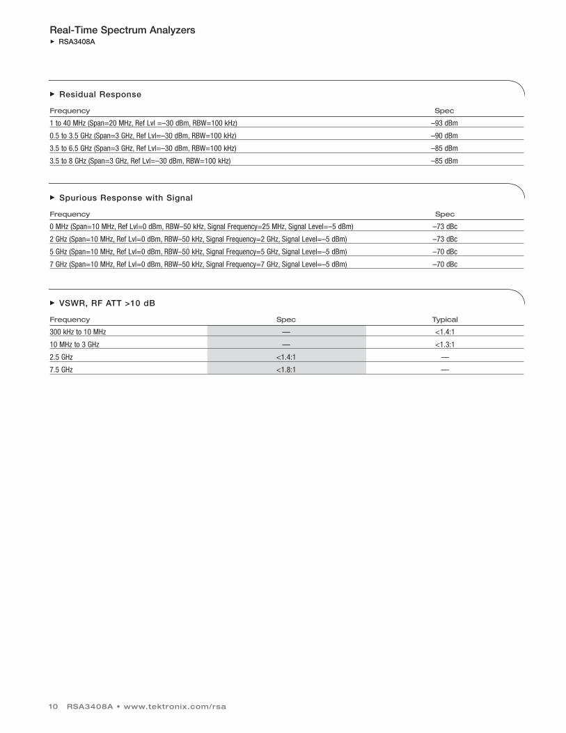
Residual Response
Frequency Spec
1 to 40 MHz (Span=20 MHz, Ref Lvl =–30 dBm, RBW=100 kHz) –93 dBm
0.5 to 3.5 GHz (Span=3 GHz, Ref Lvl=–30 dBm, RBW=100 kHz) –90 dBm
3.5 to 6.5 GHz (Span=3 GHz, Ref Lvl=–30 dBm, RBW=100 kHz) –85 dBm
3.5 to 8 GHz (Span=3 GHz, Ref Lvl=–30 dBm, RBW=100 kHz) –85 dBm
Spurious Response with Signal
Frequency Spec
0 MHz (Span=10 MHz, Ref Lvl=0 dBm, RBW–50 kHz, Signal Frequency=25 MHz, Signal Level=–5 dBm) –73 dBc
2 GHz (Span=10 MHz, Ref Lvl=0 dBm, RBW–50 kHz, Signal Frequency=2 GHz, Signal Level=–5 dBm) –73 dBc
5 GHz (Span=10 MHz, Ref Lvl=0 dBm, RBW–50 kHz, Signal Frequency=5 GHz, Signal Level=–5 dBm) –70 dBc
7 GHz (Span=10 MHz, Ref Lvl=0 dBm, RBW–50 kHz, Signal Frequency=7 GHz, Signal Level=–5 dBm) –70 dBc
VSWR, RF ATT >10 dB
Frequency Spec Typical
300 kHz to 10 MHz — <1.4:1
10 MHz to 3 GHz — <1.3:1
2.5 GHz <1.4:1 —
7.5 GHz <1.8:1 —
RSA3408A • www.tektronix.com/rsa 11
Real-Time Spectrum AnalyzersRSA3408A
INPUTS AND OUTPUTS
Front PanelInput Connectors – N type, RF/baseband; BNC type, IQ, Opt. 03.Input Impedance – 50 Ω.Preamp Power Connector – Lemo 6 pin connector – pin 1: NC; pin 2: ID1; pin3: ID2; pin 4: –12 V; pin 5: GND, pin 6: +12 V.External Preamp (Opt. 1A) – 100 MHz to 3 GHz, 20 dB gain, 6.5 dB Noise Figureat 2 GHz (typical).
Rear PanelDigital IQ Output (Opt. 05) – Connector Type – MDR (3M) 50 pin x 2.Data Output – I data: 16 bit LVDS; Q data: 16 bit LVDS.Control Output – Clock: LVDS, MAX 51.2 MHz.Control Input – IQ data output enabled, connectingGND enables output of IQ data.Clock Rising Edge to Data Transition Time(hold time) – >5 ns.Data Transition to Clock Rising Edge (set-up time) – >5 ns.Data from Opt. 05 requires application of correctionfactors to IQ data to achieve similar RF performanceto RSA3408A.
10 MHz Ref Out – 50 Ω, BNC, >–3 dBm.10 MHz Ref In – 50 Ω, BNC, –10 dBm – +6 dBm.EXT Trig In – Ext Trig, BNC, High: 1.6 to 5.0 V, Low: 0 to 0.5 V.GPIB Interface – IEEE 488.2.Trigger Out – 50 Ω, BNC, High >2.0 V, Low: <0.4 V (outputcurrent 1 mA).
Side PanelLAN Interface (Ethernet – 10/100 Base-T (Std.).Serial Interface – USB 1.1, two ports.VGA Output – VGA compatible, 15 D-sub.
General Characteristics Temperature Range – Operating: +10 ºC to +40 ºC.Storage: –20 ºC to +60 ºC.Warm-up Time – 20 min.Operating Altitude – Operating: Up to 3000 m (10,000 ft.) Non-operating: up to 12,000 m (40,000 ft.) Safety and EMI Compatibility – UL 61010-1; CSA C22.2 No. 61010-1-04;IEC61010, second edition (Self Declaration).Low Voltage Directive 73/23/EEC, amended by93/68/EEC; EN61010-1: 2001 Safety requirementsfor electrical equipment for Measurement controland laboratory use.EC Council EMC Directive 89/336/EEC, amended by 93/68/EEC.EN61326-1: 1997 Product Family Standard forElectrical Equipment for Measurement, Control and Laboratory Use-EMC Requirements.Electromagnetic Compatibility Framework:1992 AS/NZS 2064.1/2(Industrial, Scientific and Medical Equipment).Power Requirements – 100 VAC to 240 VAC,47 Hz to 63 Hz.Power Consumption – 400 VA max.Data Storage – Internal HDD (40 GB), USB port, FDD.Weight, without options – 20 kg, 44 lbs.Dimensions – Without bumpers and feet:
215 mm (H) x 425 mm (D) x 425 mm (W).With bumpers and feet:
238 mm (H) x 470 mm (D) x 445 mm (W).Calibration Interval – One year.Warranty – One year.GPIB – SCPI-compatible.
Ordering Information RSA3408A
Real-Time Spectrum Analyzer DC – 8 GHz.
Includes: User manual, Programmer’s manual,power cord, BNC-N adapter, USB keyboard and mouse.
Options*4
Opt. 1A – External Preamp, 100 MHz to 3 GHz,20 dB gain, 6.5 dB Noise Figure at 2 GHz (typical).
Opt. 1R – Rackmount kit.
Opt. 02 – 65.5 MSample Deep Memory, FrequencyMask Trigger.
Opt. 03 – IQ, Differential IQ Inputs.
Opt. 05 – Digital IQ Output.
Opt. 06 – Removable HDD.
Opt. 21 – Advanced Measurement Software Suite.
Opt. 23 – W-CDMA Uplink Analysis.*5
Opt. 24 – GSM/EDGE Analysis.
Opt. 25 – CDMA 1X Forward/Reverse Link Analysis.
Opt. 26 – 1X EVDO Forward/Reverse Link Analysis.
Opt. 27 – 3GPP Release 5 Downlink (HSDPA)Analysis.*5
Opt. 28 – TD-SCDMA Analysis.
Opt. 29 – WLAN 802.11a/b/g/n Analysis.
Opt. 40 – 3GPP Release 6 (HSUPA) Analysis.*5
*4 Specifications for Options 21 through 40 can be found in theReal-Time Spectrum Analyzer Software Options datasheet onwww.tektronix.com/RSA.
*5 Options 23 and Option 27 are required for 3GPP Release 6(HSUPA) Analysis in addition to Option 40.
Real-Time Spectrum AnalyzersRSA3408A
Contact Tektronix:ASEAN / Australasia (65) 6356 3900
Austria +41 52 675 3777
Balkan, Israel, South Africa and other ISE Countries +41 52 675 3777
Belgium 07 81 60166
Brazil & South America (11) 40669400
Canada 1 (800) 661-5625
Central East Europe, Ukraine and the Baltics +41 52 675 3777
Central Europe & Greece +41 52 675 3777
Denmark +45 80 88 1401
Finland +41 52 675 3777
France +33 (0) 1 69 86 81 81
Germany +49 (221) 94 77 400
Hong Kong (852) 2585-6688
India (91) 80-22275577
Italy +39 (02) 25086 1
Japan 81 (3) 6714-3010
Luxembourg +44 (0) 1344 392400
Mexico, Central America & Caribbean 52 (55) 5424700
Middle East, Asia and North Africa +41 52 675 3777
The Netherlands 090 02 021797
Norway 800 16098
People’s Republic of China 86 (10) 6235 1230
Poland +41 52 675 3777
Portugal 80 08 12370
Republic of Korea 82 (2) 528-5299
Russia & CIS +7 (495) 7484900
South Africa +27 11 254 8360
Spain (+34) 901 988 054
Sweden 020 08 80371
Switzerland +41 52 675 3777
Taiwan 886 (2) 2722-9622
United Kingdom & Eire +44 (0) 1344 392400
USA 1 (800) 426-2200
For other areas contact Tektronix, Inc. at: 1 (503) 627-7111
Updated 15 September 2006
Our most up-to-date product information is available at:www.tektronix.com
Copyright © 2007, Tektronix. All rights reserved. Tektronix products are covered by U.S. and foreign patents, issued and pending. Information in this publicationsupersedes that in all previously published material. Specification and pricechange privileges reserved. TEKTRONIX and TEK are registered trademarks of Tektronix, Inc. All other trade names referenced are the service marks,trademarks or registered trademarks of their respective companies.
2/07 HB/WOW 37W-18380-4
Product(s) are manufactured in ISO registered facilities.
Product(s) complies with IEEE Standard 488.1-1987, RS-232-C, and withTektronix Standard Codes and Formats.
Upgrades
RSA34UP02 – 65.5 MSample Deep Memory,Frequency Mask Trigger.
RSA34UP03 – IQ, Differential IQ Inputs.
RSA34UP05 – Digital IQ Output.
RSA34UP06 – Removable HDD.
RSA34UP21 – Advanced Measurement Suite(customer-installable).
RSA34UP23 – W-CDMA Uplink Analysis(customer-installable).
RSA34UP24 – GSM/EDGE Analysis (customer-installable).
RSA34UP25 – cdma2000 1X Forward/ReverseLink Analysis (customer-installable).
RSA34UP26 – 1X EVDO Forward/Reverse Link Analysis (customer-installable).
RSA34UP27 – 3GPP Release 6 Downlink (HSDPA) Analysis (customer-installable).*6
RSA34UP28 – TD-SCDMA Analysis (customer-installable).
RSA34UP29 – WLAN 802.11a/b/g/n Analysis (customer-installable).
RSA34UP40 – 3GPP Release 6 (HSUPA) AnalysisSoftware Upgrade (customer-installable).*6
RSA34UPIF – Installation labor for RSA34UPxx (no calibration required).
RSA34UPIFC – Installation labor for RSA34UPxx(with calibration).
*6 Option 23 and Option 27 are required for 3GPP Release 6(HSUPA) Analysis in addition to Option 40.
Accessories
RSA34RHD – Extra 40 GB Removable Hard Drive for use with Opt. 06.
RTPA2A – Probe adapter box for TekConnect®
probes.
119-4146-00 – RF Near Field Passive Probe Kit.
International Power Plugs
Opt. A0 – North America power.
Opt. A1 – Universal Euro power.
Opt. A2 – United Kingdom power.
Opt. A3 – Australia power.
Opt. A4 – North America power, 240 V.
Opt. A5 – Switzerland power.
Opt. A6 – Japan power.
Opt. A10 – China power.
Opt. A99 – No power cord.
Service
Opt. C3 – Calibration Service 3 years.
Opt. C5 – Calibration Service 5 years.
Opt. D1 – Calibration Data Report.
Opt. D3 – Calibration Data Report 3 years (with Opt. C3).
Opt. D5 – Calibration Data Report 5 years (with Opt. C5).
Opt. R3 – Repair Service 3 years.
Opt. R5 – Repair Service 5 years.
Languages
Opt. L0 – English User/Programmer’s Manuals.
Opt. L5 – Japanese User/Programmer’s Manuals.