Real-time power quality enhancement system: Power … · Engineering Ltd. 2004 Example: EQ...
8
Real-time power quality enhancement system: Power factor correction, energy savings, voltage support, flicker reduction, current spike reduction, harmonic filtration and many other applications for a variety of dynamic loads.
-
Upload
phungkhanh -
Category
Documents
-
view
215 -
download
0
Transcript of Real-time power quality enhancement system: Power … · Engineering Ltd. 2004 Example: EQ...

P. O. Box 3019,4 HaShoham St., Zone 23Caesarea Industr ia l Park,38900, ISRAELTel: +972-4-6272-470Fax: +972-4-6272-465E-Mail: [email protected]
Specifications are subject tochange without notification.All trademarks are theproperty of their respectiveowners.Copyright ELSPECEngineering Ltd. 2004
www.e l spe c - l t d . com
Example:EQ 300:60:3-400.50-P7-WFSA300kVAr real-time complete Equalizer system with 5 steps of 60 kVAr with 7%inductors, for 400V/50Hz 4-wires Wye network.Dimensions (W*D*H): 800*600*2100, Short Circuit 35kA, IP 20
EQ
P0P#DWVSFMCSMTBALR
Equalizer Complete SystemTotal power in kVArStep size in kVAr (Switching Resolution)Number of Groups (Physical, max. 12)Nominal Phase-to-Phase Voltage in VoltsNominal Frequency in Hz (50 or 60 Hz)Inrush Limiting Reactors OnlyPercents of Capacity. Example: P7 = 7%.Delta 3 wiresWye 4 wiresWye 3 wiresSingle phaseGroups protected by FusesGroups protected by MCCBsSingle Point with Integral Circuit BreakerSingle Connection PointMultiple Connection PointsTop Cable EntryBottom Cable EntryTop and Bottom Cable EntryLeft-side Cable EntryRight-side Cable Entry
System TypeTotal PowerStep SizeNo. of GroupsNominal VoltageNominal Frequency
Cable Connection
Cable Entry
Reactors Percentage
Network Typology
Group Protection
System
Type
EQ
Total
Power
1440
Step
Size
120
No. of
Groups
12
Nominal
Voltage
400
Nominal
Frequency
50
Reactors
Percentage
P7
Network
Typology
W
Group
Protection
F
Cable
Connection
C
Cable
Entry
A: : - . - -
Complete System Ordering Information
Controller Type
No. of Groups
Communication Card
EQC23
01212
Equalizer Controller
Number of Groups (Physical, two digits, max. 12)No CommunicationRS 485 ELCOM ProtocolRS 485 ELCOM and MODBUS/RTU Protocols115V230VSee Controller section on previous pagesUp to two types can be combined
Measurement Level
Power Supply
Special Type
Controller Type
EQC
Measurement Level
3
No. of Groups
12
Comm. Card
2
Power Supply
2
Special Type
WT-
Controller Ordering Information
Parameter
FrequencyPhase CurrentNeutral CurrentPhase to Phase Current*Phase VoltageNeutral VoltagePhase to Phase VoltageActive Power (kW)Reactive Power (kVAr)Apparent Power (kVA)Power FactorTime of use (TOU) - in, out, net, total:Active Energy (kWh)Reactive Energy (kVARh)THD at Phase CurrentTHD at Neutral CurrentTHD at Phase to Phase CurrentTHD at Phase VoltageTHD at Neutral VoltageTHD at Phase to Phase VoltageHarmonics of Phase CurrentHarmonics of Neutral CurrentHarmonics of Phase to Phase CurrentHarmonics of Phase VoltageHarmonics of Neutral VoltageHarmonics of Phase to Phase VoltageWaveforms of Phase CurrentWaveforms of Neutral CurrentWaveforms of Phase to Phase CurrentWaveforms of Phase VoltageWaveforms of Neutral VoltageWaveforms of Phase to Phase VoltageSystem LogEvent Log
Phases
CommonL1, L2, L3Neutral
L1-2, L2-3, L3-1L1, L2, L3Neutral
L1-2, L2-3, L3-1L1, L2, L3, TotalL1, L2, L3, TotalL1, L2, L3, TotalL1, L2, L3, Total
TotalTotal
L1, L2, L3Neutral
L1-2, L2-3, L3-1L1, L2, L3Neutral
L1-2, L2-3, L3-1L1, L2, L3Neutral
L1-2, L2-3, L3-1L1, L2, L3Neutral
L1-2, L2-3, L3-1L1, L2, L3Neutral
L1-2, L2-3, L3-1L1, L2, L3Neutral
L1-2, L2-3, L3-1
Loads
MainsMains,Load,Cap.
MainsMains , Load
MainsMainsMainsMains
Mains,Load,Cap.Mains,Load,Cap.Mains,Load,Cap.
MainsMains
Mains,Load,Cap.Mains
Mains , LoadMainsMainsMains
Mains,Load,Cap.Mains
Mains , LoadMainsMainsMains
Mains,Load,Cap.MainsMainsMainsMainsMains
Measurement Level
* Unique feature: metering internal current of feeder transformer (delta secondary)
2£
£
£
£
£
£
£
£
£
£
£
£
£
£
£
£
£
£
£
£
£
£
3£
£
£
£
£
£
£
£
£
£
£
£
£
£
£
£
£
£
£
£
£
£
£
£
£
£
£
£
£
£
£
£
Measured Parameters
ELSPEC Ltd.
Real-time power quality enhancement system:Power factor correction, energy savings,voltage support, flicker reduction, current spikereduction, harmonic filtration and many otherapplications for a variety of dynamic loads.

EQUALIZER Technology
SCAN Mode
Groups
Time
3 groupsare always engaged
Each group
is engaged
50% of
the time
1 2 3 4 5 6
6
5
4
3
2
1
Capacitor Group SwitchingThe EQUALIZER switches capacitor groupson and off using state-of-the-art electronicswitches. The connection and disconnectionof capacitors occur precisely at zero-currentcrossing. This smooth connection avoidstransient effects typically created byelectromechanically switched power factorcorrection (PFC) systems, extending the lifeexpectancy of the EQUALIZER dramatically.
SCAN ModeThe EQUALIZER is equipped with a unique SCAN feature thatprotects capacitors from exploding and contributes to longer lifeexpectancy by reducing over-current and minimizing capacitorheating. The electronic switching element (unlimited operations)connects one capacitor group simultaneously as another group isdisconnected. This operation occurs every few seconds, engagingeach capacitor group in turn, with total compensation unchanged.This results in mean current reduction due to lower duty cycle(engagement time to cycle time). Together with the unique reactordesign, temperature rise of the reactors is substantially reducedand the potential for cabinet overheating is minimized.
PowerIQ Measurement &Analysis Software (optional)This Windows-based softwarecan display the system's status,measurement results andreal-time data.
Consistent CapacityConventional electromechanicalcapacitor banks suffer from an ongoingcumulative reduction in capacity dueto the effect of transients duringconnection and disconnection. Thiscan be especially detrimental in tunedand detuned electromechanicallyswitched systems where changes inthe ratio between the capacitors andreactors shift the resonant frequency.This scenario can cause resonance,which can cause extreme damage toequipment in the facility. TheEQUALIZER prevents this scenario,resulting in longer system life, lowermaintenance costs and more consistentharmonic filtration over time.
Fast and Accurate MeasurementsThe EQUALIZER controller uses FFT (Fast Fourier Transform) analysis of all phaseseach cycle. Power information, system status and detailed logs of events are displayedon a large backlit graphic LCD screen, or via communication using the user-friendlyPowerIQ software.
L2 L3L1 L2 L3L1
2- and 3-Phase Switching Structure Electromechanical vs.Transient-free Switching
The Controller
Ideal PFC ControlUsing exclusive automatic controlalgorithms and rapid electronicswitching, total acquisition time(complete compensation of reactivecurrent) is achieved in 2/3 cycle typical(50Hz = 13.3 ms; 60Hz = 11.1 ms),irrespective of the number of stepsrequired.The power factor is controlled veryaccurately through an advanced openand closed-loop control & measuringsystem that uses information from allthree phases, as well as accounts for theeffect of harmonics (1 through 63).Minimum, maximum and average powerfactor modes, as well as threshold levels,can be selected for perfect compliancewith specific network requirements.The EQUALIZER includes a uniquesolution for line-to-line loads, in whichit calculates a transformer’s internalcurrents and compensates accordingly.Third party measurements have proventhe EQUALIZER to be the ultimatesolution to offer precise compensationfor voltage drop and flickering.
1 GroupSwitching Module
Po
we
r
Qu
al
it
y
So
lu
ti
on
s
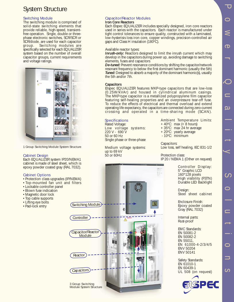
System Structure
Controller Display:5” Graphic LCD160*128 pixelsHigh visibility (FSTN)Durable LED Backlight
Design:Steel sheet cabinet
Enclosure Finish:Epoxy powder coatedGray (RAL 7032)
Internal parts:Rust-proof
EMC Standards:EN 50081-2EN 50082-2EN 55011,EN 61000-4-2/3/4/5ENV 50204ENV 50141
Safety Standards:EN 61010-1EN 60439-1UL 508 (on request)
Ambient Temperature Limits:+ 400C: max (< 8 hours)+ 350C: max 24 hr average+ 200C: yearly average - 100C: minimum
Capacitors:Low loss, self healing, IEC 831-1/2
Protection class:IP 20 / NEMA 1 (Other on request)
Cabinet DesignEach EQUALIZER system IP20/NEMA1cabinet is made of steel sheet, which isepoxy powder coated gray (RAL 7032).
Cabinet Options•Protection class upgrades (IP/NEMA)•Top-mounted fan unit and filters•Lockable controller panel•Blown fuse indication•Magnetic door lock•Top cable supports•Lifting eye bolts•Pad-lock entry
Rated Voltage:Low vol tage systems:220 V - 690 V50 or 60 HzSingle phase or three-phase
Medium voltage systems:up to 69 kV50 or 60Hz
Specifications
Capacitor/Reactor ModulesIron Core ReactorsEach Elspec EQUALIZER includes specially designed, iron core reactorsused in series with the capacitors. Each reactor is manufactured undertight control tolerances to ensure quality, constructed with a laminated,low-hysterisis loss iron core, copper windings, precision-controlled airgaps and Class H insulation (1800C).
Available reactor types:Inrush-only: Reactors designed to limit the inrush current which maydevelop in the capacitors during power up, avoiding damage to switchingelements, fuses and capacitorsDe-tuned: Prevent resonance conditions by shifting the capacitor/networkresonant frequency to below the first dominant harmonic (usually the 5th)Tuned: Designed to absorb a majority of the dominant harmonic(s), usuallythe 5th and/or 7th.
CapacitorsElspec EQUALIZER features MKP-type capacitors that are low-loss(0.25W/kVAr) and housed in cylindrical aluminum casings.The MKP-type capacitor is a metallized polypropylene film capacitorfeaturing self-healing properties and an overpressure tear-off fuse.To reduce the effects of electrical and thermal overload and extendoperating life expectancy, the capacitors are connected during zero-currentcrossing and operated in a t ime-sharing mode (SCAN).
Switching ModuleThe switching module is comprised ofsolid-state switching elements thatprovide reliable, high-speed, transient-free operation. Single, double or three-phase electronic switches, SCR/SCR orSCR/diode, are used for each capacitorgroup. Switching modules arespecifically selected for each EQUALIZERsystem based on the number of overallcapacitor groups, current requirementsand voltage ratings.
Switching Module
Controller
Capacitor/ReactorModule
Reactor
Capacitors
1 Group Switching Module System Structure
3 Group SwitchingModule System Structure
Po
we
r
Qu
al
it
y
So
lu
ti
on
s
System Structure
Controller Display:5” Graphic LCD160*128 pixelsHigh visibility (FSTN)Durable LED Backlight
Design:Steel sheet cabinet
Enclosure Finish:Epoxy powder coatedGray (RAL 7032)
Internal parts:Rust-proof
EMC Standards:EN 50081-2EN 50082-2EN 55011,EN 61000-4-2/3/4/5ENV 50204ENV 50141
Safety Standards:EN 61010-1EN 60439-1UL 508 (on request)
Ambient Temperature Limits:+ 400C: max (< 8 hours)+ 350C: max 24 hr average+ 200C: yearly average - 100C: minimum
Capacitors:Low loss, self healing, IEC 831-1/2
Protection class:IP 20 / NEMA 1 (Other on request)
Cabinet DesignEach EQUALIZER system IP20/NEMA1cabinet is made of steel sheet, which isepoxy powder coated gray (RAL 7032).
Cabinet Options•Protection class upgrades (IP/NEMA)•Top-mounted fan unit and filters•Lockable controller panel•Blown fuse indication•Magnetic door lock•Top cable supports•Lifting eye bolts•Pad-lock entry
Rated Voltage:Low vol tage systems:220 V - 690 V50 or 60 HzSingle phase or three-phase
Medium voltage systems:up to 69 kV50 or 60Hz
Specifications
Capacitor/Reactor ModulesIron Core ReactorsEach Elspec EQUALIZER includes specially designed, iron core reactorsused in series with the capacitors. Each reactor is manufactured undertight control tolerances to ensure quality, constructed with a laminated,low-hysterisis loss iron core, copper windings, precision-controlled airgaps and Class H insulation (1800C).
Available reactor types:Inrush-only: Reactors designed to limit the inrush current which maydevelop in the capacitors during power up, avoiding damage to switchingelements, fuses and capacitorsDe-tuned: Prevent resonance conditions by shifting the capacitor/networkresonant frequency to below the first dominant harmonic (usually the 5th)Tuned: Designed to absorb a majority of the dominant harmonic(s), usuallythe 5th and/or 7th.
CapacitorsElspec EQUALIZER features MKP-type capacitors that are low-loss(0.25W/kVAr) and housed in cylindrical aluminum casings.The MKP-type capacitor is a metallized polypropylene film capacitorfeaturing self-healing properties and an overpressure tear-off fuse.To reduce the effects of electrical and thermal overload and extendoperating life expectancy, the capacitors are connected during zero-currentcrossing and operated in a t ime-sharing mode (SCAN).
Switching ModuleThe switching module is comprised ofsolid-state switching elements thatprovide reliable, high-speed, transient-free operation. Single, double or three-phase electronic switches, SCR/SCR orSCR/diode, are used for each capacitorgroup. Switching modules arespecifically selected for each EQUALIZERsystem based on the number of overallcapacitor groups, current requirementsand voltage ratings.
Switching Module
Controller
Capacitor/ReactorModule
Reactor
Capacitors
1 Group Switching Module System Structure
3 Group SwitchingModule System Structure
A digital signal processor (DSP) and a VLSIcomponent form the basis of the controller’stechnology. It features an LCD display, analogand digital circuitry, precise firing algorithmsand optional communication capabilities.The controller has 9 input channels: 4 voltages(for Wye networks), 3 main currents and 2internal system currents. The informationobtained from these measurements is usedfor Fast Fourier Transform (FFT) analysis,performed each network cycle on allchannels. The advanced control algorithm,which includes unique patent-pendingtechnology for fast compensation, calculatesthe required compensation in 1ms. Further,harmonics are calculated on all phases,allowing the EQUALIZER to achieve idealcompensation even in the presence ofharmonics.
The EQUALIZER’s controller is available witha choice of data gathering levels, fromessential power parameter measurementsonly (V, I, f, kW, kVA, kVAr) to completepower system performance monitoring thattakes advantage of the comprehensivemeasurement system (over 2,000 electricalparameters, including min/max levels andfour-quadrant measurement of power andpower factor).
The large LCD display is full-graphic, 160x128pixels, and has long-lasting LED backlightingwith FSTN technology. Characters aredisplayed in varying sizes and methods toenhance visibility. These include a LargeDigits display, Harmonic spectrums, real-timeWaveform plots and simple Text screens thatinclude menus, easy-to-use setup programsand various measurements.
The Controller
This optional proprietary software works in parallel with the on-board controller, displaying system status and measurement resultsin a Windows operating environment, and allows the user remote-access to control various parameters of EQUALIZER system.All network parameters, including harmonics, can be recorded continually or for pre-selected intervals. Recording time is limitedonly by the size of the computer's hard disk or other storage device (server, memory card, etc). Electrical events can be capturedby associating trigger values to various network power parameters, such as low voltage or high current. The event recording willcapture a user-selected before and after window of time. PowerIQ has intranet and internet support capabilities.
PowerIQ - Measurement & Analysis Software
Digits Display Waveform Display
Harmonic Bar Display Text Display
PowerIQ Windows Examples
The Equalizer controller is available with several configuration options (seeordering information on back page of catalog):
Unbalanced system for three-phase networks with single-phase capacitorsSingle phase system for single-phase networks with single-phase capacitorsWind Energy, a version specifically designed for wind turbine generatorapplicationsVoltage Control, where the controller connects or disconnects stepsaccording to user-defined voltage limits (6-level)Medium Voltage compensation, using LV capacitors and step-downtransformerMedium Voltage compensation, using MV capacitors (see Type T)Generator applications, allows two power factor targets dependent ongenerator mode of operationExternal trigger signal for synchronized compensation, allowing instantaneouscompensation (0ms)
USW
V
T
MG
P
---
-
-
--
-
Po
we
r
Qu
al
it
y
So
lu
ti
on
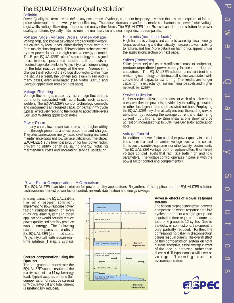
sThe EQUALIZER Power Quality SolutionDefinitionPower Quality is a term used to define any occurrence of voltage, current or frequency deviation that results in equipment failure,process interruptions or power system inefficiency. These deviations can manifest themselves in harmonics, power factor, voltagesags/swells, voltage flickering, transients and many other forms. The EQUALIZER from Elspec is an all-in-one solution for powerquality problems, typically installed near the main service and near major distribution panels.
Voltage Sags (Voltage Drops, Under-Voltage)Voltage sags, also known as voltage drops or under-voltage,are caused by local loads, either during motor startup orfrom rapidly changing loads. This condition is characterizedby low power factor and high reactive energy demand.The Elspec EQUALIZER’s ultra-fast technology is designedto act in these specialized conditions. It connects allrequired capacitor banks in 2/3 cycle typical, compensatingfor the total reactive energy of the event. Moreover, itchanges the direction of the voltage drop vector to minimizethe sag. As a result, the voltage sag is minimized and inmany cases, even eliminated (See Motor Startup andElevator application notes on next page).
Voltage FlickeringVoltage flickering is caused by fast voltage fluctuationscommonly associated with rapid loads, such as spotwelders. The EQUALIZER’s control technology connectsand disconnects all required capacitor banks in 2/3 cycletypical, effectively reducing the flicker to acceptable levels(See Spot Welding application note).
Power FactorIn many cases, low power factors result in higher utilitybills through penalties and increased demand charges.They also cause system energy losses, overheating, increasedmaintenance costs and low service utilization. The ElspecEQUALIZER is the foremost solution for low power factor,preventing utility penalties, saving energy, reducingmaintenance costs and increasing service utilization.
Harmonics (non-linear loads)High harmonic voltages and currents cause significant energylosses, overheating and dramatically increase site vulnerabilityto failures and fire. More details on harmonics appear underthe applications section on next page.
Spikes (Transients)Spikes (transients) can cause significant damage to equipment,produce unpredicted power supply failures and degradecapacitors. The EQUALIZER solution uses transient-freeswitching technology to eliminate all spikes associated withconventional capacitor switching. The results are longercapacitor life expectancy, less maintenance costs and highernetwork reliability.
Service UtilizationHigher service utilization is a constant wish of all electricityusers, whether the power is provided by the utility, generatorsor other local generation such as wind turbines. Employingthe EQUALIZER may dramatically increase the existing serviceutilization by reducing the average current and stabilizingcurrent fluctuations. Existing installations show serviceutilization increases of up to 60% (See Generator applicationnote).
Voltage ControlIn addition to power factor and other power quality issues, attimes there is a need to maintain voltage levels within certainlimits due to sensitive equipment or other facility requirements.The EQUALIZER voltage control option offers 6 differentvoltage control levels that facilitate both high and lowparameters. The voltage control operates in parallel with thepower factor control and complements it.
Power Factor Compensation – A ComparisonThe EQUALIZER is an ideal solution for power quality applications. Regardless of the application, the EQUALIZER solutionachieves near-perfect power factor control, network stabilization and energy savings.
In many cases, the EQUALIZER isthe only proper so lu t ion.Implementing slow-response powerfactor compensation or evenquasi-real-time systems in theseapplications would actually reducepower quality and possibly producewasted energy. The followingexample compares the results ofthe EQUALIZER (unlimited steps,2/3 cycle typical) with a quasi-real-time solution (1 step, 3 cycles):
Correct compensation using theEqualizerThe top graphs demonstrate theEQUALIZER’s compensation of thereactive current in a 14-cycle energyload. Typical acquisition time (fullcompensation of reactive current)is 2/3 cycle typical and total currentis substantially reduced.
Adverse effects of slower responsesystemsThe bottom graphs demonstrate incorrectcompensation where response time is 3cycles to connect a single group andacquisition time required to connect atotal of 4 groups is 12 cycles. Due tothe delay in connections, the current isonly partially reduced. Further, thecorresponding delay in disconnectioncauses residual current. The overall effectof this compensation system on totalcurrent is negative, as the average currentof the load is increased, rather thandecreased. This phenomena will increasev o l t a g e f l i c k e r i n g d u e t oovercompensation.
Cycles
0.2
0.6
1.0
Acquisition Time
Equalizer Current
1.0
1.0
1.0
1.0
0 2 4 6 8 10 12 14 16 18 20 22 24
Current of slow response system(3 cycles per step)
Correctcompensation
Incorrectcompensation
Total Current with Equalizer
Total Current with slowresponse system
Load Current
Acquisition Time
Po
we
r
Qu
al
it
y
So
lu
ti
on
sThe EQUALIZER Power Quality SolutionDefinitionPower Quality is a term used to define any occurrence of voltage, current or frequency deviation that results in equipment failure,process interruptions or power system inefficiency. These deviations can manifest themselves in harmonics, power factor, voltagesags/swells, voltage flickering, transients and many other forms. The EQUALIZER from Elspec is an all-in-one solution for powerquality problems, typically installed near the main service and near major distribution panels.
Voltage Sags (Voltage Drops, Under-Voltage)Voltage sags, also known as voltage drops or under-voltage,are caused by local loads, either during motor startup orfrom rapidly changing loads. This condition is characterizedby low power factor and high reactive energy demand.The Elspec EQUALIZER’s ultra-fast technology is designedto act in these specialized conditions. It connects allrequired capacitor banks in 2/3 cycle typical, compensatingfor the total reactive energy of the event. Moreover, itchanges the direction of the voltage drop vector to minimizethe sag. As a result, the voltage sag is minimized and inmany cases, even eliminated (See Motor Startup andElevator application notes on next page).
Voltage FlickeringVoltage flickering is caused by fast voltage fluctuationscommonly associated with rapid loads, such as spotwelders. The EQUALIZER’s control technology connectsand disconnects all required capacitor banks in 2/3 cycletypical, effectively reducing the flicker to acceptable levels(See Spot Welding application note).
Power FactorIn many cases, low power factors result in higher utilitybills through penalties and increased demand charges.They also cause system energy losses, overheating, increasedmaintenance costs and low service utilization. The ElspecEQUALIZER is the foremost solution for low power factor,preventing utility penalties, saving energy, reducingmaintenance costs and increasing service utilization.
Harmonics (non-linear loads)High harmonic voltages and currents cause significant energylosses, overheating and dramatically increase site vulnerabilityto failures and fire. More details on harmonics appear underthe applications section on next page.
Spikes (Transients)Spikes (transients) can cause significant damage to equipment,produce unpredicted power supply failures and degradecapacitors. The EQUALIZER solution uses transient-freeswitching technology to eliminate all spikes associated withconventional capacitor switching. The results are longercapacitor life expectancy, less maintenance costs and highernetwork reliability.
Service UtilizationHigher service utilization is a constant wish of all electricityusers, whether the power is provided by the utility, generatorsor other local generation such as wind turbines. Employingthe EQUALIZER may dramatically increase the existing serviceutilization by reducing the average current and stabilizingcurrent fluctuations. Existing installations show serviceutilization increases of up to 60% (See Generator applicationnote).
Voltage ControlIn addition to power factor and other power quality issues, attimes there is a need to maintain voltage levels within certainlimits due to sensitive equipment or other facility requirements.The EQUALIZER voltage control option offers 6 differentvoltage control levels that facilitate both high and lowparameters. The voltage control operates in parallel with thepower factor control and complements it.
Power Factor Compensation – A ComparisonThe EQUALIZER is an ideal solution for power quality applications. Regardless of the application, the EQUALIZER solutionachieves near-perfect power factor control, network stabilization and energy savings.
In many cases, the EQUALIZER isthe only proper so lu t ion.Implementing slow-response powerfactor compensation or evenquasi-real-time systems in theseapplications would actually reducepower quality and possibly producewasted energy. The followingexample compares the results ofthe EQUALIZER (unlimited steps,2/3 cycle typical) with a quasi-real-time solution (1 step, 3 cycles):
Correct compensation using theEqualizerThe top graphs demonstrate theEQUALIZER’s compensation of thereactive current in a 14-cycle energyload. Typical acquisition time (fullcompensation of reactive current)is 2/3 cycle typical and total currentis substantially reduced.
Adverse effects of slower responsesystemsThe bottom graphs demonstrate incorrectcompensation where response time is 3cycles to connect a single group andacquisition time required to connect atotal of 4 groups is 12 cycles. Due tothe delay in connections, the current isonly partially reduced. Further, thecorresponding delay in disconnectioncauses residual current. The overall effectof this compensation system on totalcurrent is negative, as the average currentof the load is increased, rather thandecreased. This phenomena will increasev o l t a g e f l i c k e r i n g d u e t oovercompensation.
Cycles
0.2
0.6
1.0
Acquisition Time
Equalizer Current
1.0
1.0
1.0
1.0
0 2 4 6 8 10 12 14 16 18 20 22 24
Current of slow response system(3 cycles per step)
Correctcompensation
Incorrectcompensation
Total Current with Equalizer
Total Current with slowresponse system
Load Current
Acquisition Time

Po
we
r
Qu
al
it
y
So
lu
ti
on
s
Motor Start-upWhen connected directly to the line, large squirrel-caseinductive motors consume very high current during thestart-up period (six times higher than steady state operation).This high current consumption can lead to significantvoltage drops on both the low and high voltage sides ofthe transformer, which interfere with other loads, reduceinitial torque and increase start-up time. The EQUALIZERsystem tracks the reactive current and fully compensatesit in 2/3 cycle typical, offering the following benefits:•Protection against voltage drop on the main service•Capability to central-start all loads, avoiding the use of•individual starters commonly used to protect against•voltage drop•Direct connection of motors to main service, obtaining•maximum torque during start-ups. This benefit is unique•to the EQUALIZER solution, as starters of all types•typically reduce the current going through the motor,•thereby reducing the starting torque.
Applications
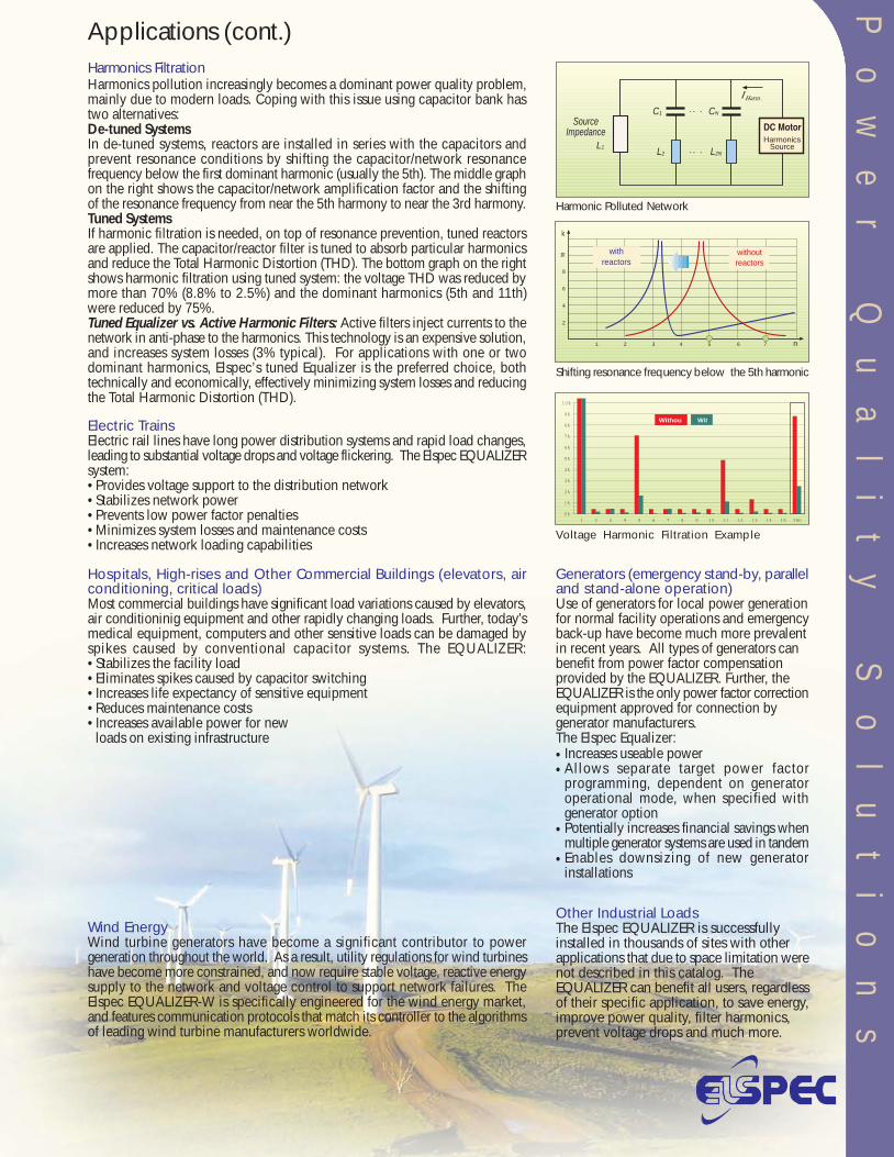
Electric TrainsElectric rail lines have long power distribution systems and rapid load changes,leading to substantial voltage drops and voltage flickering. The Elspec EQUALIZERsystem:•Provides voltage support to the distribution network•Stabilizes network power•Prevents low power factor penalties•Minimizes system losses and maintenance costs•Increases network loading capabilities
Hospitals, High-rises and Other Commercial Buildings (elevators, airconditioning, critical loads)Most commercial buildings have significant load variations caused by elevators,air conditioninig equipment and other rapidly changing loads. Further, today’smedical equipment, computers and other sensitive loads can be damaged byspikes caused by conventional capacitor systems. The EQUALIZER:•Stabilizes the facility load•Eliminates spikes caused by capacitor switching•Increases life expectancy of sensitive equipment•Reduces maintenance costs•Increases available power for new•loads on existing infrastructure
Applications (cont.)
1 2 3 4 5 6 7 n
withreactors
withoutreactors
k
2
4
6
8
10
Shifting resonance frequency below the 5th harmonic
-
C1 CN
L2 L2NL1
SourceImpedance
HarmonicsSource
Welding MachinesSpot welding loads fluctuate extremely rapidly and consume large amounts ofreactive power. Due to high current changes caused by the near-instantaneousreactive energy consumption, large voltage drops are produced. These sagsreduce weld quality and decrease welding productivity. Additionally, these loadsoften create a high incidence of voltage flickering, which frequently exceedsrecommended IEEE limits. Elspec’s real-time EQUALIZER benefits:•Improved weld quality and reduced scrap/rework•Increased process output•Reduced voltage flickering•Enhanced service utilization for the facility (better utilization of the existing power infrastructure)•Reduced maintenance costsThe top graph on the right demonstrates how the EQUALIZER prevents voltagedrop and flickering, substantially reduces the current and fully compensatesreactive energy requirements. The bottom graph on the right illustrates weldertips DC current with and without the EQUALIZER solution. Optimal weldingconditions require a stable current at the weld tips. In this example, currentvariations are reduced by 75% with the EQUALIZER solution (±200A vs. ±800A).
Harbor CranesThe complete operation cycle of harbor cranes is approximatelyone minute. During this time, the crane requires variableamounts of reactive energy, fluctuating rapidly throughoutthe entire crane cycle.The Elspec EQUALIZER’s real-time solution:•Stabilizes the voltage•Reduces the current•Allows installation of a smaller•service (less cable, less heat)•Lowers system losses•Saves energy
Plastic Injection MoldingDue to widely varying unsynchronized load conditions, plasticinjection molding applications have rapid & inconsistent reactiveenergy requirements. Power supply failure during a productioncycle can cause enormous financial and physical damage causedby plastic cooling inside the machines. Besides reducing overallsystem energy losses, Elspec’s EQUALIZER solution drasticallyreduces the risk for such an event by stabilizing the current andvoltage levels in the facility on a cycle-by-cycle basis.
Wind EnergyWind turbine generators have become a significant contributor to powergeneration throughout the world. As a result, utility regulations for wind turbineshave become more constrained, and now require stable voltage, reactive energysupply to the network and voltage control to support network failures. TheElspec EQUALIZER-W is specifically engineered for the wind energy market,and features communication protocols that match its controller to the algorithmsof leading wind turbine manufacturers worldwide.
Spot Welding - Car Industry
DC Current at Welder Tip
AC Motor Startup Voltage Harmonic Filtration Example
Harmonic Polluted Network
0%
1%
2%
3%
4%
5%
6%
7%
8%
9%
10%
1 2 3 4 5 6 7 8 9 10 11 12 13 14 15 THD
WitWithou
Generators (emergency stand-by, paralleland stand-alone operation)Use of generators for local power generationfor normal facility operations and emergencyback-up have become much more prevalentin recent years. All types of generators canbenefit from power factor compensationprovided by the EQUALIZER. Further, theEQUALIZER is the only power factor correctionequipment approved for connection bygenerator manufacturers.The Elspec Equalizer:
Other Industrial LoadsThe Elspec EQUALIZER is successfullyinstalled in thousands of sites with otherapplications that due to space limitation werenot described in this catalog. TheEQUALIZER can benefit all users, regardlessof their specific application, to save energy,improve power quality, filter harmonics,prevent voltage drops and much more.
••
•
•
Increases useable powerAllows separate target power factorprogramming, dependent on generatoroperational mode, when specified withgenerator optionPotentially increases financial savings whenmultiple generator systems are used in tandemEnables downsizing of new generatorinstallations
Harmonics pollution increasingly becomes a dominant power quality problem,mainly due to modern loads. Coping with this issue using capacitor bank hastwo alternatives:De-tuned SystemsIn de-tuned systems, reactors are installed in series with the capacitors andprevent resonance conditions by shifting the capacitor/network resonancefrequency below the first dominant harmonic (usually the 5th). The middle graphon the right shows the capacitor/network amplification factor and the shiftingof the resonance frequency from near the 5th harmony to near the 3rd harmony.Tuned SystemsIf harmonic filtration is needed, on top of resonance prevention, tuned reactorsare applied. The capacitor/reactor filter is tuned to absorb particular harmonicsand reduce the Total Harmonic Distortion (THD). The bottom graph on the rightshows harmonic filtration using tuned system: the voltage THD was reduced bymore than 70% (8.8% to 2.5%) and the dominant harmonics (5th and 11th)were reduced by 75%.Tuned Equalizer vs. Active Harmonic Filters: Active filters inject currents to thenetwork in anti-phase to the harmonics. This technology is an expensive solution,and increases system losses (3% typical). For applications with one or twodominant harmonics, Elspec’s tuned Equalizer is the preferred choice, bothtechnically and economically, effectively minimizing system losses and reducingthe Total Harmonic Distortion (THD).
Harmonics Filtration
210
220
230
1000
1500
Voltage (V)
Current (A)
500
Time [0.2 sec./Div]
210
220
230
1400
1800
0
150
300
Voltage (V)
Current (A)
Q (kVAr)
1000
WithWithout
Time [2 sec./Div]
With Without
10400
10600
10800
11000
11200
11400
11600
11800
1 2 3 4 5 6 7 8 9 10
Spot Number
Amps
With Without
Po
we
r
Qu
al
it
y
So
lu
ti
on
s
Motor Start-upWhen connected directly to the line, large squirrel-caseinductive motors consume very high current during thestart-up period (six times higher than steady state operation).This high current consumption can lead to significantvoltage drops on both the low and high voltage sides ofthe transformer, which interfere with other loads, reduceinitial torque and increase start-up time. The EQUALIZERsystem tracks the reactive current and fully compensatesit in 2/3 cycle typical, offering the following benefits:•Protection against voltage drop on the main service•Capability to central-start all loads, avoiding the use of•individual starters commonly used to protect against•voltage drop•Direct connection of motors to main service, obtaining•maximum torque during start-ups. This benefit is unique•to the EQUALIZER solution, as starters of all types•typically reduce the current going through the motor,•thereby reducing the starting torque.
Applications
Electric TrainsElectric rail lines have long power distribution systems and rapid load changes,leading to substantial voltage drops and voltage flickering. The Elspec EQUALIZERsystem:•Provides voltage support to the distribution network•Stabilizes network power•Prevents low power factor penalties•Minimizes system losses and maintenance costs•Increases network loading capabilities
Hospitals, High-rises and Other Commercial Buildings (elevators, airconditioning, critical loads)Most commercial buildings have significant load variations caused by elevators,air conditioninig equipment and other rapidly changing loads. Further, today’smedical equipment, computers and other sensitive loads can be damaged byspikes caused by conventional capacitor systems. The EQUALIZER:•Stabilizes the facility load•Eliminates spikes caused by capacitor switching•Increases life expectancy of sensitive equipment•Reduces maintenance costs•Increases available power for new•loads on existing infrastructure
Applications (cont.)
1 2 3 4 5 6 7 n
withreactors
withoutreactors
k
2
4
6
8
10
Shifting resonance frequency below the 5th harmonic
-
C1 CN
L2 L2NL1
SourceImpedance
HarmonicsSource
Welding MachinesSpot welding loads fluctuate extremely rapidly and consume large amounts ofreactive power. Due to high current changes caused by the near-instantaneousreactive energy consumption, large voltage drops are produced. These sagsreduce weld quality and decrease welding productivity. Additionally, these loadsoften create a high incidence of voltage flickering, which frequently exceedsrecommended IEEE limits. Elspec’s real-time EQUALIZER benefits:•Improved weld quality and reduced scrap/rework•Increased process output•Reduced voltage flickering•Enhanced service utilization for the facility (better utilization of the existing power infrastructure)•Reduced maintenance costsThe top graph on the right demonstrates how the EQUALIZER prevents voltagedrop and flickering, substantially reduces the current and fully compensatesreactive energy requirements. The bottom graph on the right illustrates weldertips DC current with and without the EQUALIZER solution. Optimal weldingconditions require a stable current at the weld tips. In this example, currentvariations are reduced by 75% with the EQUALIZER solution (±200A vs. ±800A).
Harbor CranesThe complete operation cycle of harbor cranes is approximatelyone minute. During this time, the crane requires variableamounts of reactive energy, fluctuating rapidly throughoutthe entire crane cycle.The Elspec EQUALIZER’s real-time solution:•Stabilizes the voltage•Reduces the current•Allows installation of a smaller•service (less cable, less heat)•Lowers system losses•Saves energy
Plastic Injection MoldingDue to widely varying unsynchronized load conditions, plasticinjection molding applications have rapid & inconsistent reactiveenergy requirements. Power supply failure during a productioncycle can cause enormous financial and physical damage causedby plastic cooling inside the machines. Besides reducing overallsystem energy losses, Elspec’s EQUALIZER solution drasticallyreduces the risk for such an event by stabilizing the current andvoltage levels in the facility on a cycle-by-cycle basis.
Wind EnergyWind turbine generators have become a significant contributor to powergeneration throughout the world. As a result, utility regulations for wind turbineshave become more constrained, and now require stable voltage, reactive energysupply to the network and voltage control to support network failures. TheElspec EQUALIZER-W is specifically engineered for the wind energy market,and features communication protocols that match its controller to the algorithmsof leading wind turbine manufacturers worldwide.
Spot Welding - Car Industry
DC Current at Welder Tip
AC Motor Startup Voltage Harmonic Filtration Example
Harmonic Polluted Network
0%
1%
2%
3%
4%
5%
6%
7%
8%
9%
10%
1 2 3 4 5 6 7 8 9 10 11 12 13 14 15 THD
WitWithou
Generators (emergency stand-by, paralleland stand-alone operation)Use of generators for local power generationfor normal facility operations and emergencyback-up have become much more prevalentin recent years. All types of generators canbenefit from power factor compensationprovided by the EQUALIZER. Further, theEQUALIZER is the only power factor correctionequipment approved for connection bygenerator manufacturers.The Elspec Equalizer:
Other Industrial LoadsThe Elspec EQUALIZER is successfullyinstalled in thousands of sites with otherapplications that due to space limitation werenot described in this catalog. TheEQUALIZER can benefit all users, regardlessof their specific application, to save energy,improve power quality, filter harmonics,prevent voltage drops and much more.
••
•
•
Increases useable powerAllows separate target power factorprogramming, dependent on generatoroperational mode, when specified withgenerator optionPotentially increases financial savings whenmultiple generator systems are used in tandemEnables downsizing of new generatorinstallations
Harmonics pollution increasingly becomes a dominant power quality problem,mainly due to modern loads. Coping with this issue using capacitor bank hastwo alternatives:De-tuned SystemsIn de-tuned systems, reactors are installed in series with the capacitors andprevent resonance conditions by shifting the capacitor/network resonancefrequency below the first dominant harmonic (usually the 5th). The middle graphon the right shows the capacitor/network amplification factor and the shiftingof the resonance frequency from near the 5th harmony to near the 3rd harmony.Tuned SystemsIf harmonic filtration is needed, on top of resonance prevention, tuned reactorsare applied. The capacitor/reactor filter is tuned to absorb particular harmonicsand reduce the Total Harmonic Distortion (THD). The bottom graph on the rightshows harmonic filtration using tuned system: the voltage THD was reduced bymore than 70% (8.8% to 2.5%) and the dominant harmonics (5th and 11th)were reduced by 75%.Tuned Equalizer vs. Active Harmonic Filters: Active filters inject currents to thenetwork in anti-phase to the harmonics. This technology is an expensive solution,and increases system losses (3% typical). For applications with one or twodominant harmonics, Elspec’s tuned Equalizer is the preferred choice, bothtechnically and economically, effectively minimizing system losses and reducingthe Total Harmonic Distortion (THD).
Harmonics Filtration
210
220
230
1000
1500
Voltage (V)
Current (A)
500
Time [0.2 sec./Div]
210
220
230
1400
1800
0
150
300
Voltage (V)
Current (A)
Q (kVAr)
1000
WithWithout
Time [2 sec./Div]
With Without
10400
10600
10800
11000
11200
11400
11600
11800
1 2 3 4 5 6 7 8 9 10
Spot Number
Amps
With Without

A digital signal processor (DSP) and a VLSIcomponent form the basis of the controller’stechnology. It features an LCD display, analogand digital circuitry, precise firing algorithmsand optional communication capabilities.The controller has 9 input channels: 4 voltages(for Wye networks), 3 main currents and 2internal system currents. The informationobtained from these measurements is usedfor Fast Fourier Transform (FFT) analysis,performed each network cycle on allchannels. The advanced control algorithm,which includes unique patent-pendingtechnology for fast compensation, calculatesthe required compensation in 1ms. Further,harmonics are calculated on all phases,allowing the EQUALIZER to achieve idealcompensation even in the presence ofharmonics.
The EQUALIZER’s controller is available witha choice of data gathering levels, fromessential power parameter measurementsonly (V, I, f, kW, kVA, kVAr) to completepower system performance monitoring thattakes advantage of the comprehensivemeasurement system (over 2,000 electricalparameters, including min/max levels andfour-quadrant measurement of power andpower factor).
The large LCD display is full-graphic, 160x128pixels, and has long-lasting LED backlightingwith FSTN technology. Characters aredisplayed in varying sizes and methods toenhance visibility. These include a LargeDigits display, Harmonic spectrums, real-timeWaveform plots and simple Text screens thatinclude menus, easy-to-use setup programsand various measurements.
The Controller
This optional proprietary software works in parallel with the on-board controller, displaying system status and measurement resultsin a Windows operating environment, and allows the user remote-access to control various parameters of EQUALIZER system.All network parameters, including harmonics, can be recorded continually or for pre-selected intervals. Recording time is limitedonly by the size of the computer's hard disk or other storage device (server, memory card, etc). Electrical events can be capturedby associating trigger values to various network power parameters, such as low voltage or high current. The event recording willcapture a user-selected before and after window of time. PowerIQ has intranet and internet support capabilities.
PowerIQ - Measurement & Analysis Software
Digits Display Waveform Display
Harmonic Bar Display Text Display
PowerIQ Windows Examples
The Equalizer controller is available with several configuration options (seeordering information on back page of catalog):
Unbalanced system for three-phase networks with single-phase capacitorsSingle phase system for single-phase networks with single-phase capacitorsWind Energy, a version specifically designed for wind turbine generatorapplicationsVoltage Control, where the controller connects or disconnects stepsaccording to user-defined voltage limits (6-level)Medium Voltage compensation, using LV capacitors and step-downtransformerMedium Voltage compensation, using MV capacitors (see Type T)Generator applications, allows two power factor targets dependent ongenerator mode of operationExternal trigger signal for synchronized compensation, allowing instantaneouscompensation (0ms)
USW
V
T
MG
P
---
-
-
--
-
Po
we
r
Qu
al
it
y
So
lu
ti
on
s
The EQUALIZER Power Quality SolutionDefinitionPower Quality is a term used to define any occurrence of voltage, current or frequency deviation that results in equipment failure,process interruptions or power system inefficiency. These deviations can manifest themselves in harmonics, power factor, voltagesags/swells, voltage flickering, transients and many other forms. The EQUALIZER from Elspec is an all-in-one solution for powerquality problems, typically installed near the main service and near major distribution panels.
Voltage Sags (Voltage Drops, Under-Voltage)Voltage sags, also known as voltage drops or under-voltage,are caused by local loads, either during motor startup orfrom rapidly changing loads. This condition is characterizedby low power factor and high reactive energy demand.The Elspec EQUALIZER’s ultra-fast technology is designedto act in these specialized conditions. It connects allrequired capacitor banks in 2/3 cycle typical, compensatingfor the total reactive energy of the event. Moreover, itchanges the direction of the voltage drop vector to minimizethe sag. As a result, the voltage sag is minimized and inmany cases, even eliminated (See Motor Startup andElevator application notes on next page).
Voltage FlickeringVoltage flickering is caused by fast voltage fluctuationscommonly associated with rapid loads, such as spotwelders. The EQUALIZER’s control technology connectsand disconnects all required capacitor banks in 2/3 cycletypical, effectively reducing the flicker to acceptable levels(See Spot Welding application note).
Power FactorIn many cases, low power factors result in higher utilitybills through penalties and increased demand charges.They also cause system energy losses, overheating, increasedmaintenance costs and low service utilization. The ElspecEQUALIZER is the foremost solution for low power factor,preventing utility penalties, saving energy, reducingmaintenance costs and increasing service utilization.
Harmonics (non-linear loads)High harmonic voltages and currents cause significant energylosses, overheating and dramatically increase site vulnerabilityto failures and fire. More details on harmonics appear underthe applications section on next page.
Spikes (Transients)Spikes (transients) can cause significant damage to equipment,produce unpredicted power supply failures and degradecapacitors. The EQUALIZER solution uses transient-freeswitching technology to eliminate all spikes associated withconventional capacitor switching. The results are longercapacitor life expectancy, less maintenance costs and highernetwork reliability.
Service UtilizationHigher service utilization is a constant wish of all electricityusers, whether the power is provided by the utility, generatorsor other local generation such as wind turbines. Employingthe EQUALIZER may dramatically increase the existing serviceutilization by reducing the average current and stabilizingcurrent fluctuations. Existing installations show serviceutilization increases of up to 60% (See Generator applicationnote).
Voltage ControlIn addition to power factor and other power quality issues, attimes there is a need to maintain voltage levels within certainlimits due to sensitive equipment or other facility requirements.The EQUALIZER voltage control option offers 6 differentvoltage control levels that facilitate both high and lowparameters. The voltage control operates in parallel with thepower factor control and complements it.
Power Factor Compensation – A ComparisonThe EQUALIZER is an ideal solution for power quality applications. Regardless of the application, the EQUALIZER solutionachieves near-perfect power factor control, network stabilization and energy savings.
In many cases, the EQUALIZER isthe only proper so lu t ion.Implementing slow-response powerfactor compensation or evenquasi-real-time systems in theseapplications would actually reducepower quality and possibly producewasted energy. The followingexample compares the results ofthe EQUALIZER (unlimited steps,2/3 cycle typical) with a quasi-real-time solution (1 step, 3 cycles):
Correct compensation using theEqualizerThe top graphs demonstrate theEQUALIZER’s compensation of thereactive current in a 14-cycle energyload. Typical acquisition time (fullcompensation of reactive current)is 2/3 cycle typical and total currentis substantially reduced.
Adverse effects of slower responsesystemsThe bottom graphs demonstrate incorrectcompensation where response time is 3cycles to connect a single group andacquisition time required to connect atotal of 4 groups is 12 cycles. Due tothe delay in connections, the current isonly partially reduced. Further, thecorresponding delay in disconnectioncauses residual current. The overall effectof this compensation system on totalcurrent is negative, as the average currentof the load is increased, rather thandecreased. This phenomena will increasev o l t a g e f l i c k e r i n g d u e t oovercompensation.
Cycles
0.2
0.6
1.0
Acquisition Time
Equalizer Current
1.0
1.0
1.0
1.0
0 2 4 6 8 10 12 14 16 18 20 22 24
Current of slow response system(3 cycles per step)
Correctcompensation
Incorrectcompensation
Total Current with Equalizer
Total Current with slowresponse system
Load Current
Acquisition Time
EQUALIZER Technology
SCAN Mode
Groups
Time
3 groupsare always engaged
Each group
is engaged
50% of
the time
1 2 3 4 5 6
6
5
4
3
2
1
Capacitor Group SwitchingThe EQUALIZER switches capacitor groupson and off using state-of-the-art electronicswitches. The connection and disconnectionof capacitors occur precisely at zero-currentcrossing. This smooth connection avoidstransient effects typically created byelectromechanically switched power factorcorrection (PFC) systems, extending the lifeexpectancy of the EQUALIZER dramatically.
SCAN ModeThe EQUALIZER is equipped with a unique SCAN feature thatprotects capacitors from exploding and contributes to longer lifeexpectancy by reducing over-current and minimizing capacitorheating. The electronic switching element (unlimited operations)connects one capacitor group simultaneously as another group isdisconnected. This operation occurs every few seconds, engagingeach capacitor group in turn, with total compensation unchanged.This results in mean current reduction due to lower duty cycle(engagement time to cycle time). Together with the unique reactordesign, temperature rise of the reactors is substantially reducedand the potential for cabinet overheating is minimized.
PowerIQ Measurement &Analysis Software (optional)This Windows-based softwarecan display the system's status,measurement results andreal-time data.
Consistent CapacityConventional electromechanicalcapacitor banks suffer from an ongoingcumulative reduction in capacity dueto the effect of transients duringconnection and disconnection. Thiscan be especially detrimental in tunedand detuned electromechanicallyswitched systems where changes inthe ratio between the capacitors andreactors shift the resonant frequency.This scenario can cause resonance,which can cause extreme damage toequipment in the facility. TheEQUALIZER prevents this scenario,resulting in longer system life, lowermaintenance costs and more consistentharmonic filtration over time.
Fast and Accurate MeasurementsThe EQUALIZER controller uses FFT (Fast Fourier Transform) analysis of all phaseseach cycle. Power information, system status and detailed logs of events are displayedon a large backlit graphic LCD screen, or via communication using the user-friendlyPowerIQ software.
L2 L3L1 L2 L3L1
2- and 3-Phase Switching Structure Electromechanical vs.Transient-free Switching
The Controller
Ideal PFC ControlUsing exclusive automatic controlalgorithms and rapid electronicswitching, total acquisition time(complete compensation of reactivecurrent) is achieved in 2/3 cycle typical(50Hz = 13.3 ms; 60Hz = 11.1 ms),irrespective of the number of stepsrequired.The power factor is controlled veryaccurately through an advanced openand closed-loop control & measuringsystem that uses information from allthree phases, as well as accounts for theeffect of harmonics (1 through 63).Minimum, maximum and average powerfactor modes, as well as threshold levels,can be selected for perfect compliancewith specific network requirements.The EQUALIZER includes a uniquesolution for line-to-line loads, in whichit calculates a transformer’s internalcurrents and compensates accordingly.Third party measurements have proventhe EQUALIZER to be the ultimatesolution to offer precise compensationfor voltage drop and flickering.
1 GroupSwitching Module
Po
we
r
Qu
al
it
y
So
lu
ti
on
sSystem Structure
Controller Display:5” Graphic LCD160*128 pixelsHigh visibility (FSTN)Durable LED Backlight
Design:Steel sheet cabinet
Enclosure Finish:Epoxy powder coatedGray (RAL 7032)
Internal parts:Rust-proof
EMC Standards:EN 50081-2EN 50082-2EN 55011,EN 61000-4-2/3/4/5ENV 50204ENV 50141
Safety Standards:EN 61010-1EN 60439-1UL 508 (on request)
Ambient Temperature Limits:+ 400C: max (< 8 hours)+ 350C: max 24 hr average+ 200C: yearly average - 100C: minimum
Capacitors:Low loss, self healing, IEC 831-1/2
Protection class:IP 20 / NEMA 1 (Other on request)
Cabinet DesignEach EQUALIZER system IP20/NEMA1cabinet is made of steel sheet, which isepoxy powder coated gray (RAL 7032).
Cabinet Options•Protection class upgrades (IP/NEMA)•Top-mounted fan unit and filters•Lockable controller panel•Blown fuse indication•Magnetic door lock•Top cable supports•Lifting eye bolts•Pad-lock entry
Rated Voltage:Low vol tage systems:220 V - 690 V50 or 60 HzSingle phase or three-phase
Medium voltage systems:up to 69 kV50 or 60Hz
Specifications
Capacitor/Reactor ModulesIron Core ReactorsEach Elspec EQUALIZER includes specially designed, iron core reactorsused in series with the capacitors. Each reactor is manufactured undertight control tolerances to ensure quality, constructed with a laminated,low-hysterisis loss iron core, copper windings, precision-controlled airgaps and Class H insulation (1800C).
Available reactor types:Inrush-only: Reactors designed to limit the inrush current which maydevelop in the capacitors during power up, avoiding damage to switchingelements, fuses and capacitorsDe-tuned: Prevent resonance conditions by shifting the capacitor/networkresonant frequency to below the first dominant harmonic (usually the 5th)Tuned: Designed to absorb a majority of the dominant harmonic(s), usuallythe 5th and/or 7th.
CapacitorsElspec EQUALIZER features MKP-type capacitors that are low-loss(0.25W/kVAr) and housed in cylindrical aluminum casings.The MKP-type capacitor is a metallized polypropylene film capacitorfeaturing self-healing properties and an overpressure tear-off fuse.To reduce the effects of electrical and thermal overload and extendoperating life expectancy, the capacitors are connected during zero-currentcrossing and operated in a t ime-sharing mode (SCAN).
Switching ModuleThe switching module is comprised ofsolid-state switching elements thatprovide reliable, high-speed, transient-free operation. Single, double or three-phase electronic switches, SCR/SCR orSCR/diode, are used for each capacitorgroup. Switching modules arespecifically selected for each EQUALIZERsystem based on the number of overallcapacitor groups, current requirementsand voltage ratings.
Switching Module
Controller
Capacitor/ReactorModule
Reactor
Capacitors
1 Group Switching Module System Structure
3 Group SwitchingModule System Structure
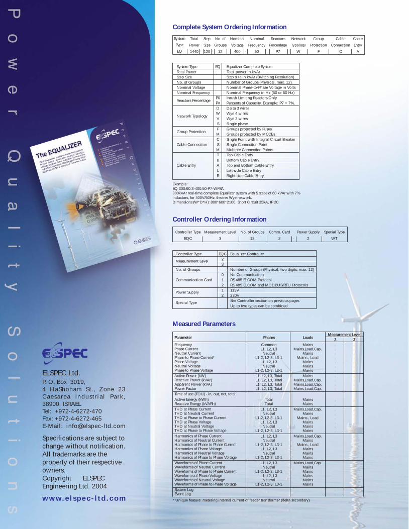
P. O. Box 3019,4 HaShoham St., Zone 23Caesarea Industr ia l Park,38900, ISRAELTel: +972-4-6272-470Fax: +972-4-6272-465E-Mail: [email protected]
Specifications are subject tochange without notification.All trademarks are theproperty of their respectiveowners.Copyright ELSPECEngineering Ltd. 2004
www.e l sp ec - l t d . com
Example:EQ 300:60:3-400.50-P7-WFSA300kVAr real-time complete Equalizer system with 5 steps of 60 kVAr with 7%inductors, for 400V/50Hz 4-wires Wye network.Dimensions (W*D*H): 800*600*2100, Short Circuit 35kA, IP 20
EQ
P0P#DWVSFMCSMTBALR
Equalizer Complete SystemTotal power in kVArStep size in kVAr (Switching Resolution)Number of Groups (Physical, max. 12)Nominal Phase-to-Phase Voltage in VoltsNominal Frequency in Hz (50 or 60 Hz)Inrush Limiting Reactors OnlyPercents of Capacity. Example: P7 = 7%.Delta 3 wiresWye 4 wiresWye 3 wiresSingle phaseGroups protected by FusesGroups protected by MCCBsSingle Point with Integral Circuit BreakerSingle Connection PointMultiple Connection PointsTop Cable EntryBottom Cable EntryTop and Bottom Cable EntryLeft-side Cable EntryRight-side Cable Entry
System TypeTotal PowerStep SizeNo. of GroupsNominal VoltageNominal Frequency
Cable Connection
Cable Entry
Reactors Percentage
Network Typology
Group Protection
System
Type
EQ
Total
Power
1440
Step
Size
120
No. of
Groups
12
Nominal
Voltage
400
Nominal
Frequency
50
Reactors
Percentage
P7
Network
Typology
W
Group
Protection
F
Cable
Connection
C
Cable
Entry
A: : - . - -
Complete System Ordering Information
Controller Type
No. of Groups
Communication Card
EQC23
01212
Equalizer Controller
Number of Groups (Physical, two digits, max. 12)No CommunicationRS 485 ELCOM ProtocolRS 485 ELCOM and MODBUS/RTU Protocols115V230VSee Controller section on previous pagesUp to two types can be combined
Measurement Level
Power Supply
Special Type
Controller Type
EQC
Measurement Level
3
No. of Groups
12
Comm. Card
2
Power Supply
2
Special Type
WT-
Controller Ordering Information
Parameter
FrequencyPhase CurrentNeutral CurrentPhase to Phase Current*Phase VoltageNeutral VoltagePhase to Phase VoltageActive Power (kW)Reactive Power (kVAr)Apparent Power (kVA)Power FactorTime of use (TOU) - in, out, net, total:Active Energy (kWh)Reactive Energy (kVARh)THD at Phase CurrentTHD at Neutral CurrentTHD at Phase to Phase CurrentTHD at Phase VoltageTHD at Neutral VoltageTHD at Phase to Phase VoltageHarmonics of Phase CurrentHarmonics of Neutral CurrentHarmonics of Phase to Phase CurrentHarmonics of Phase VoltageHarmonics of Neutral VoltageHarmonics of Phase to Phase VoltageWaveforms of Phase CurrentWaveforms of Neutral CurrentWaveforms of Phase to Phase CurrentWaveforms of Phase VoltageWaveforms of Neutral VoltageWaveforms of Phase to Phase VoltageSystem LogEvent Log
Phases
CommonL1, L2, L3Neutral
L1-2, L2-3, L3-1L1, L2, L3Neutral
L1-2, L2-3, L3-1L1, L2, L3, TotalL1, L2, L3, TotalL1, L2, L3, TotalL1, L2, L3, Total
TotalTotal
L1, L2, L3Neutral
L1-2, L2-3, L3-1L1, L2, L3Neutral
L1-2, L2-3, L3-1L1, L2, L3Neutral
L1-2, L2-3, L3-1L1, L2, L3Neutral
L1-2, L2-3, L3-1L1, L2, L3Neutral
L1-2, L2-3, L3-1L1, L2, L3Neutral
L1-2, L2-3, L3-1
Loads
MainsMains,Load,Cap.
MainsMains , Load
MainsMainsMainsMains
Mains,Load,Cap.Mains,Load,Cap.Mains,Load,Cap.
MainsMains
Mains,Load,Cap.Mains
Mains , LoadMainsMainsMains
Mains,Load,Cap.Mains
Mains , LoadMainsMainsMains
Mains,Load,Cap.MainsMainsMainsMainsMains
Measurement Level
* Unique feature: metering internal current of feeder transformer (delta secondary)
2£
£
£
£
£
£
£
£
£
£
£
£
£
£
£
£
£
£
£
£
£
£
3£
£
£
£
£
£
£
£
£
£
£
£
£
£
£
£
£
£
£
£
£
£
£
£
£
£
£
£
£
£
£
£
Measured Parameters
ELSPEC Ltd.
Real-time power quality enhancement system:Power factor correction, energy savings,voltage support, flicker reduction, current spikereduction, harmonic filtration and many otherapplications for a variety of dynamic loads.


![Kvar Presentation Ppt 8.8.08[1]](https://static.fdocuments.in/doc/165x107/5552cecab4c90581158b50da/kvar-presentation-ppt-88081.jpg)