
Establishing a Hardware-in-the-Loop Research Environment ...
This is a repository copy of Real-Time Hardware-in-the-Loop Simulation of Permanent Magnet Synchronous Motor Drives under Stator Faults.
White Rose Research Online URL for this paper:http://eprints.whiterose.ac.uk/114042/
Version: Accepted Version
Article:
Alvarez-Gonzalez, F., Griffo, A. orcid.org/0000-0001-5642-2921, Sen, B. et al. (1 more author) (2017) Real-Time Hardware-in-the-Loop Simulation of Permanent Magnet Synchronous Motor Drives under Stator Faults. IEEE Transactions on Industrial Electronics. ISSN 0278-0046
https://doi.org/10.1109/TIE.2017.2688969
[email protected]://eprints.whiterose.ac.uk/
Reuse
Unless indicated otherwise, fulltext items are protected by copyright with all rights reserved. The copyright exception in section 29 of the Copyright, Designs and Patents Act 1988 allows the making of a single copy solely for the purpose of non-commercial research or private study within the limits of fair dealing. The publisher or other rights-holder may allow further reproduction and re-use of this version - refer to the White Rose Research Online record for this item. Where records identify the publisher as the copyright holder, users can verify any specific terms of use on the publisher’s website.
Takedown
If you consider content in White Rose Research Online to be in breach of UK law, please notify us by emailing [email protected] including the URL of the record and the reason for the withdrawal request.

IEEE TRANSACTIONS ON INDUSTRIAL ELECTRONICS
Abstract—Hardware-in-the-loop (HIL) testing methods
can facilitate the development of control strategies in a safe and inexpensive environment particularly when extreme operating conditions such as faults are considered. HIL methods rely on accurate real-time emulation of the equipment under investigation. However, no validated tools for real-time emulation of electrical drives under fault conditions are available. This paper describes the implementation of a high-fidelity real-time emulator of a Permanent Magnet Synchronous Motor (PMSM) drive in a platform suitable for HIL tests. The emulator is capable of representing the drive operation under both healthy conditions and during inter-turn stator winding faults. Nonlinearities due to saturation, higher order harmonics, slotting effects, etc. are accounted for using four-dimensional look-up tables obtained by finite element analysis (FEA). The proposed model is computationally efficient and capable of running in real-time in a FPGA platform and is validated against simulations and experimental results in a wide range of operating conditions. Potential applications of the proposed emulation environment to the development of drive control, fault detection and diagnostic algorithms are proposed.
Index Terms— Fault modelling, FPGA, Hardware-in-the-Loop, Permanent Magnet Synchronous Motor.
NOMENCLATURE
id d-axis current iq q-axis current i f Fault current ょd d-axis flux linkage ょq q-axis flux linkage ょf Flux linkage in faulted turns た ratio of faulted turns to total number of turns Rs Stator phase resistance Rf Fault resistance のe Angular electrical speed しe Electrical rotor angle
Manuscript received July 12, 2016; revised January 13, 2017;
accepted March 13, 2017. The authors are with the Electrical Machines and Drives Research
Group, Department of Electronic and Electrical Engineering, The
I. INTRODUCTION
ARDWARE-in-the-Loop (HIL) methodologies whereby a piece of hardware is substituted by an accurate real-time
emulation, have gained widespread acceptance as a tool for rapid testing and development of data acquisition systems, electronics and control strategies in a large number of industrial applications including automotive, energy or aerospace sectors where safety implications, cost and complexity of full scale prototyping might be significant. HIL methods can be used as tools to develop control strategies for components and systems in all operating conditions including extreme conditions such as those resulting from faults in a safe, non-destructive environment. Due to the increasing use of PMSM drives in safety critical applications such as automotive traction and aerospace actuation, HIL methods capable of accurately emulating motor drives in all operating modes including faulty conditions, can provide drive systems integrators with a useful and relatively inexpensive tool for the development and testing of fault-detection, diagnostic techniques as well as post-fault control actions.
Although many motor drive emulators for HIL testing have recently been proposed in academic research and by commercial vendors, so far no validated method capable of accurately emulating in real-time the dynamics of a machine under faulty conditions has been demonstrated. The main contribution of the paper is demonstrating a novel real-time emulation of PMSM drives suitable for HIL testing of both healthy and faulty conditions considering in particular inter-turn stator short-circuit faults which have been identified as a major cause of electrical failure in a machine [1]. Short-circuit faults typically starts with inter-turn faults [2] which can eventually result in demagnetization or further catastrophic failure due to large circulating currents [3].
The degree of fidelity by which HIL systems emulate the physical behavior of the device under testing in realistic operating conditions, depends on the availability of an accurate representation of the physical system under investigation.
University of Sheffield, Sheffield, S1 4DE, U.K. (e-mail: [email protected], [email protected])
Real-Time Hardware-in-the-Loop Simulation of Permanent Magnet Synchronous Motor
Drives under Stator Faults
Fernando Alvarez-Gonzalez, Student Member, IEEE, Antonio Griffo, Member, IEEE, Bhaskar Sen, Member, IEEE, and Jiabin Wang, Senior Member, IEEE
H
IEEE TRANSACTIONS ON INDUSTRIAL ELECTRONICS
Although detailed models such as those based on time-domain co-simulation of Finite Elements (FE) provide a high degree of fidelity, their computational complexity prevents their applicability to the real-time computation required for HIL simulation. Real-time simulation of electric motor drives is particularly challenging due to the fast nature of the dynamics involved. Commutation of PWM signals at tens of kHz requires sampling rates in the order of several MHz in order to obtain reasonable accuracy. Field Programmable Gate Arrays (FPGAs) are emerging as the platform of choice for complex real-time simulations due to their ability to process data in parallel allowing for sampling rates and execution up to the MHz range.
HIL emulation of electric machines and drives has been proposed for Induction Motors (IM) [4]-[10] and PMSM [9]-[19]. Due to the requirements for computational efficiency, most of the published methods for real-time emulation of electric machines rely on analytical models with various degrees of simplifications. A HIL model for IM based on permeance network (PN) is presented in [5]. A similar approach based on non-linear Magnetic Equivalent Circuit (MEC) is employed to model IM in [7]. A unified framework for FPGA-based emulation of electrical machines based on state-space representation with constant inductances is presented in [10]. A real-time model based on the analytical solution of field equations to account for space harmonics in the air-gap flux density distribution of PMSM has been developed in [11] under the assumption of linear superposition.
While analytical models based on PN, MEC or analytical field solutions can achieve the computational efficiency required for real-time implementation, they might lack generality, requiring significant effort to adapt models to different topologies. Furthermore, analytical models are often based on simplifying assumptions of linearity/superposition which might not be generally applicable. Models based on pre-calculated FE solutions and stored in look-up tables for real-time implementation have been proposed as an easier to implement and more general solution to take into account non-linearities in machine behavior [5],[12],[14],[15],[20]. A real-time PMSM model taking into account angular variation of phase inductances due to space harmonics and slotting effects has been proposed [12]. However, the use of constant inductance-based model lacks the ability to account for non-linearities due to saturation of the magnetic circuit. Even if current dependent inductances are used, the separation of flux linkages in armature reaction and permanent magnet induced fluxes is only valid under linear conditions. Similar models based on pre-tabulated inductances and flux maps accounting for saturation and spatial harmonics have been proposed in [13]-[15]. However, these require proprietary tools and are based on variable inductances which pose problems in real-time simulation in voltage-driven models as the nonlinear relation between flux linkages and currents may not be easily inverted in real-time calculations. The use of differential inductances and pre-calculated inversion of current-flux relationship is proposed in [21].
Although many of the solutions proposed in literature
successfully address the issues of accuracy and computational efficiency for real-time emulation of a drive system in healthy conditions, no general method capable of accurately emulating the dynamics of a machine under faulty conditions has been presented. Models of stator winding inter-turn short-circuits for PMSM have been proposed based on a number of analytical modelling techniques including the use of Dynamic Mesh Reluctances Model (DMRM) [22], PN [23] and constant inductances [24]-[25]. Besides the relative complexity in the derivation of the model and the inevitable simplifying assumptions required in most analytical models, the difficulty in accounting for the angular variation of flux linkages due to high-order harmonics in the back-EMF or slotting effects in these models has led to the development of machine models based on the extraction of flux linkage maps from FE magnetostatic computations as function of stator currents and rotor position [20], [26]. The model accounts for often neglected dependence of flux linkages on rotor angular position and can easily be extended to account for operation under inter-turn short circuits [27]. The rest of the paper describes the real-time implementation of a high-fidelity non-linear model of PMSM drive under both healthy and inter-turn stator winding short-circuit conditions. The method, based on [27], results in an accurate, yet computationally efficient modelling technique since the terminal current versus stator flux linkages relationships are pre-calculated off-line and stored in look-up tables during real-time operation. Practical implementation in a FPGA-based platform is illustrated and validation of the proposed emulation is presented both against FE simulations and experimental tests over a wide range of operating conditions. Results show a good degree of accuracy on the real-time emulation while maintaining a low computational complexity for implementation on low-cost hardware.
II. HIGH FIDELITY FAULT MODEL OF PMSM
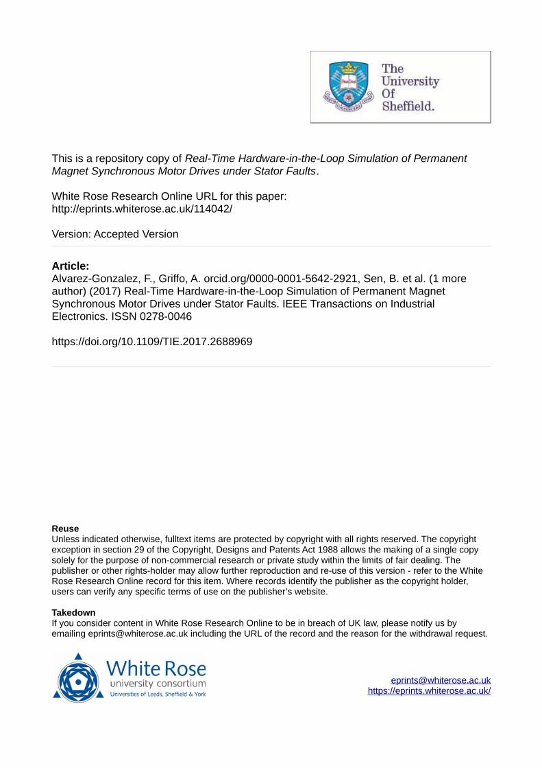
The proposed modelling framework for PMSM under inter-turn short-circuit fault is adapted from [27] and illustrated with reference to Fig. 1. Without loss of generality, the turn fault is assumed to be in phase C divided into a healthy and a faulty coils denoted as 系朕 and 系捗 respectively. The fault is modelled by a fault resistance 迎捗 ┸ and the fault current is denoted by 件捗 ┻ The ratio of short-circuited turns to the total number of turns in the phase winding is indicated with 航.
Figure 1. Three-phase stator winding with inter-turn short circuit fault.
Rf
ic
ia
ic-if
ib
Ch
Cf
C
B
A

IEEE TRANSACTIONS ON INDUSTRIAL ELECTRONICS
A. Analytical Model in dq-Frame
In the synchronous 穴圏 reference frame the voltage equations describing the stator flux linkages dynamics can be demonstrated to be [27]: 懸鳥 噺 迎鎚件鳥 髪 穴閤鳥穴建 伐 降勅閤槌 伐 にぬ 航迎鎚 sin 磐肯勅 髪 にぬ 講卑 件捗 (1a) 懸槌 噺 迎鎚件槌 髪 穴閤槌穴建 髪 降勅閤鳥 伐 にぬ 航迎鎚 cos 磐肯勅 髪 にぬ 講卑 件捗 (1b)
while the voltage across the shorted turns is given by: 懸捗 噺 迎捗件捗 噺 航迎鎚盤件鳥 sin岫肯勅 髪 に講【ぬ岻 髪 件槌 cos岫肯勅 髪 に講【ぬ岻伐 件捗匪 髪 穴皇捗穴建 ┻ (2)
The relationships between stator flux linkages, stator currents and rotor mechanical angular position 肯陳 is given by the non-linear four-dimensional maps: 皇鳥 噺 血鳥岫件鳥 ┸ 件槌 ┸ 件捗┸ 肯陳岻 (3) 皇槌 噺 血槌岫件鳥 ┸ 件槌 ┸ 件捗┸ 肯陳岻 (4) 皇捗 噺 血捗岫件鳥 ┸ 件槌 ┸ 件捗┸ 肯陳岻 (5)
which can be extracted from a set of magnetostatic FE computations and stored in lookup tables. Saturation, spatial saliency and harmonics are accounted for. Although neglected here, iron losses and thermal effects can also be included in the same modelling framework [28]. Integration of (1)-(2) requires the inversion of the flux maps (3)-(5) to give: 件鳥 噺 血鳥貸怠岫皇鳥 ┸ 皇槌 ┸ 皇捗┸ 肯陳岻 (6) 件槌 噺 血槌貸怠岫皇鳥 ┸ 皇槌 ┸ 皇捗┸ 肯陳岻 (7) 件捗 噺 血捗貸怠岫皇鳥 ┸ 皇槌 ┸ 皇捗 ┸ 肯陳岻 (8)
While this inversion could in principle be achieved in dynamic simulations using e.g. iterative algorithms, given the non-linearity of (3)-(5), it would result in computationally intensive calculations which could be very challenging for real-time implementation. Instead, the current maps (6)-(8) are pre-calculated offline and stored in four-dimensional lookup-tables.
B. FE model
Figure 2. Full FE model of the employed IPM machine.
Validation of the proposed modelling methodology is performed with reference to a three-phase, 6-pole and 36-slot permanent magnet assisted synchronous reluctance machine designed to maximize reluctance torque, whose cross-section is shown in Fig. 2. The machine has 2 slots per pole per phase and incorporates a 3-step rotor skew of 7º (mech) modelled
according to the method described in [27]. Laminations were manufactured by a process of laser cutting whose detrimental effect on machine performance is taken into account in the FE model by addition of extra air gaps.
Two turns in phase C have been modelled discretely to allow for inter-turn short-circuit emulation. Faults in any other phase can be easily simulated without the need to run any further FE computation, by simply shifting the rotor electrical angle as:
肯勅 噺 崔肯勅 伐 に【ぬ講 fault in phase a肯勅 伐 ね【ぬ講 fault in phase b肯勅 fault in phase c (9)
III. HARDWARE IMPLEMENTATION
Real-time implementation requires discretization of eqs. (1)-(2). The chosen algorithm could have implications on accuracy and stability of the numerical simulation depending on the discretization time step [29]. The computational efficiency of the model allows the choice of relatively small time step (~1s) compared to the electrical time constants guaranteeing stability and accuracy. For simplicity in implementation the forward Euler discretization is used resulting in:
閤鳥岫倦 髪 な岻 噺 閤鳥岫倦岻 髪 つ建 峙懸鳥岫倦岻 伐 迎鎚件鳥岫倦岻 髪降勅岫倦岻閤槌岫倦岻 髪 態戴 航迎鎚 sin岫肯勅岫倦岻 髪 に【ぬ講岻件捗岫倦岻峩 (30a)
閤槌岫倦 髪 な岻 噺 閤槌岫倦岻 髪 つ建 峙懸槌岫倦岻 伐 迎鎚件槌岫倦岻 伐降勅岫倦岻閤鳥岫倦岻 髪 態戴 航迎鎚 cos岫肯勅岫倦岻 髪 に【ぬ講岻件捗岫倦岻峩 (10b)
閤捗岫倦 髪 な岻 噺 閤捗岫倦岻髪 つ建 峙懸捗岫倦岻伐 航迎鎚 岾件鳥岫倦岻 sin岫肯勅岫倦岻 髪 に講【ぬ岻髪 件槌岫倦岻 cos岫肯勅岫倦岻 髪 に【ぬ講岻伐 件捗岫倦岻峇峩 (10c)
Figure 3. Block diagram illustrating the Hardware-in-the-Loop arrangement.
The developed
model is implemented on a commercially available data

IEEE TRANSACTIONS ON INDUSTRIAL ELECTRONICS
acquisition and control platform NI cRIO-9082. The code is implemented on the Spartan-6 LX150 FPGA-based chassis and programmed through LabVIEW FPGA. The FPGA is clocked at 40MHz. Six PWM gate drives digital inputs are sampled at 5MHz. Output currents are generated with a digital-to-analog conversion at 115 kHz rate. A schematic of the proposed arrangement in a typical Controller-in-the-loop testing is shown in Fig 3.
A 32-bit fixed-point representation is used for the internal variables. A schematic diagram illustrating the emulation step is shown in Fig.4.
Figure 4. Hardware-in-the-loop design configuration.
State variables and outputs of the model are the stator flux linkages, rotor angle and currents, respectively. Current output calculation is based on the four-dimensional current maps (6)-(8). Since FPGAs do not support multidimensional memory storage, the four-dimensional arrays containing dq-axes and fault currents as functions of 閤鳥 ┸ 閤槌 ┸ 閤捗 ┸ 肯 have been rearranged in a one-dimensional array. A computationally efficient method of memory addressing based on four-dimensional linear interpolations on one-dimensional arrays of
data has been implemented as schematically illustrated in Fig.5. The 4D table look-up is based on the application of four successive one dimensional interpolations. Appropriate offsets, depending on the spatial discretization in the 閤鳥 ┸ 閤槌 ┸ 閤捗 ┸ 肯 space and the resulting number of elements in the tables, are required to access the correct position in the unidimensional memory array. For the case under study there are 12 steps in 穴-axis flux, 圏-axis flux, and faulted coil flux and 61 steps in rotor position し, resulting in 105,408 elements per current map. Given the relative complexity of such system, pipelining must be employed for parallel data processing.
For computational efficiency and speed of execution only FPGA’s internal block RAM is used for data storage of the look-up tables. The use of incremental inductances proposed e.g. in [21] might have increased storage requirements resulting in the need for additional external memory with additional overhead in terms of access time.
TABLE I. THREE PHASE CONVERTER SWITCHING STATES
Switching state
Switches ON
Space vector
Va Vb Vc
0 Q2,Q4,Q6 V1(0,0,0) 0 0 0
1 Q1,Q4,Q6 V2(1,0,0) 態戴 Vdc 伐 怠戴 Vdc 伐 怠戴 Vdc
2 Q1,Q3,Q6 V3(1,1,0) 怠戴 Vdc
怠戴 Vdc 伐 態戴 Vdc
3 Q2,Q3,Q5 V4(0,1,0) 伐 怠戴 Vdc 態戴 Vdc 伐 怠戴 Vdc
4 Q2,Q4,Q5 V5(0,1,1) 伐 態戴 Vdc 怠戴 Vdc
怠戴 Vdc
5 Q1,Q4,Q5 V6(0,0,1) 伐 怠戴 Vdc 伐 怠戴 Vdc 態戴 Vdc
6 Q1,Q4,Q5 V7(1,0,1) 怠戴 Vdc 伐 態戴 Vdc
怠戴 Vdc
7 Q1,Q3,Q5 V8(1,1,1) 0 0 0
Figure 5. Interpolation system block diagram.
Three phase converter emulation has been carried out considering only 8 switching states including two zero states as seen in Table I. Dead times are not considered for this application but can be easily included.
Current maps & interpolation
Idqf
しょdqf
ょdqf & しId
Iq
If
Id-map
Angle Calculation & CORDIC implementation
DQ-axes & fault flux linkage calculation
ょdqf
のe
し
のe
のe し
+-
+/-+
ょdqVdq
Idq Rs
ょd/q のe
If た 2/3 Rs sin-cos(し+2ヾ/3)
+--+
ょf
If Rf
Id た Rs cos(し+2ヾ/3)
Iq た Rs cos(し+2ヾ/3)
If た Rs
Current transformation
Iabc
Idqf
し
し
dq/gく gく/abcIdIq
Iabc
し
++
++
++
x
x
〉T(s)
x
〉T(s) 権貸怠
権貸怠
権貸怠
Converter emulation
Bin/Dec
Vg
VくSwitchCase
PWM Signals‘Va’
‘Vb’
‘Vc’
Vgく
Vgく
sinし
cosしCO
RD
IC
Iq-map
If-map
MemoryD-current
Memory node
Memory node
Memory node
Memory node
Integer part
Integer part
Integer part
Offset x
Fractionalpart
Fractionalpart
Fractionalpart
ょd
ょq
ょf
IdMemory position
Offset y
Offset z
Memory node
Integer part
Fractionalpart
しOffset t
IEEE TRANSACTIONS ON INDUSTRIAL ELECTRONICS
TABLE II.
HARDWARE RESOURCES EMPLOYED IN REAL-TIME SIMULATION
Resources Slice
Registers Slice LUTs Block RAMs
DSP48 Blocks
Total Emulator
7235/184304 3.9%
14622/92152 15.9%
265/268 98.9%
166/180 92.2%
DQ to ABC transformation
1039/184304 0.6%
794/92152 0.9%
0/268 0%
4/180 2.2%
Current Maps &
Interpolation
1218/184304 0.7%
1646/92152 1.8%
265/268 98.9%
0/180 0%
Flux Equations 1668/184304
0.9% 1487/92152
1.6% 0/268 0%
16/180 8.9%
Angle Calculation
1675/184304 0.9%
2074/92152 2.3%
0/268 0%
30/180 16.7%
Output & Measure
1617/184304 0.9%
1617/92152 1.8%
0/268 0%
1/180 0.6%
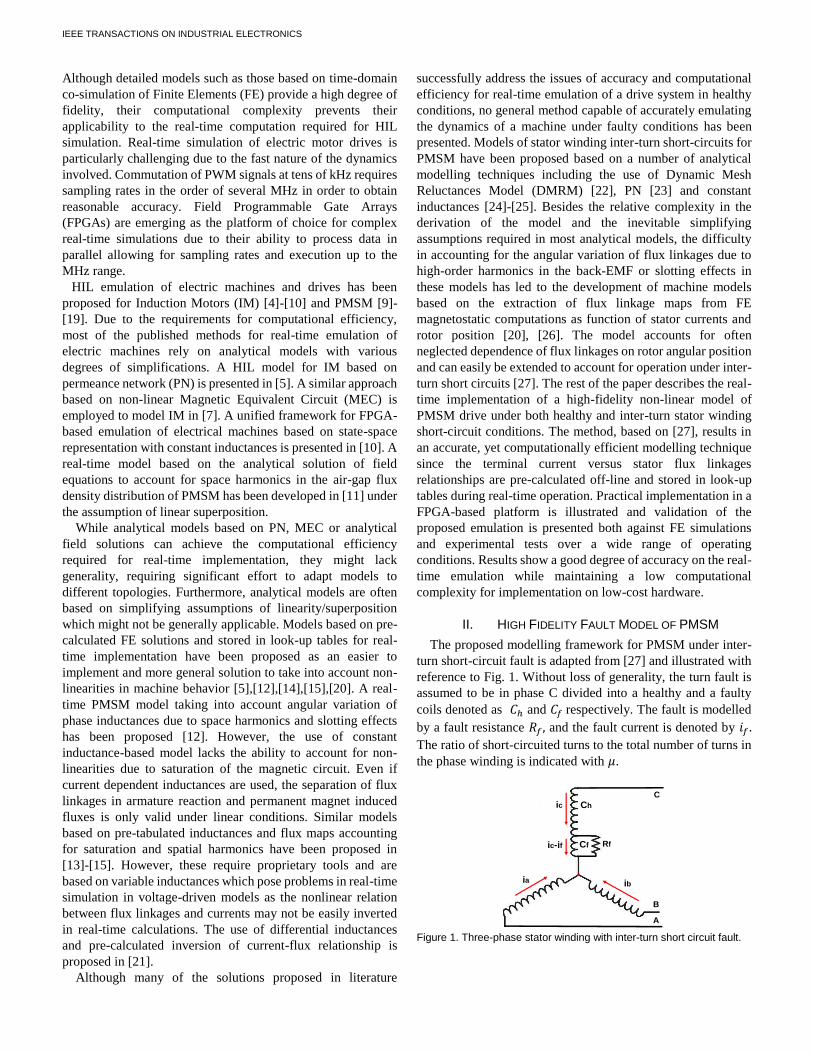
Table II lists the FPGA resource usage for the proposed
model. The most demanding subsystem in terms of resources is the look-up table allocation which results in 99% usage of the available block RAM. Most of the arithmetic calculations based on adders/multiplier and accumulator is implemented using the available DSP48 blocks. Higher resolution in the current/flux maps, and hence bigger look-up tables, can easily be obtained with bigger and more expensive FPGAs or using external RAM.
TABLE III. NUMBER OF CYCLES AND RATE OF EXECUTION OF REAL-TIME
SIMULATION
Cycles & Execution
Number of Cycles
Rate of Execution
DQ to ABC transformation
10 250ns
Current Maps & Interpolation
50 1.25たs
Flux Equations 8 200ns
Angle Calculation 43 1.075たs
Output & Measure 349 8.725たs
Table III lists the rate of execution of each sub-system of the
real-time simulation. In particular the table shows the number of cycles of the 40MHz clock required for the calculation of each subsystem. The most demanding is the current maps interpolation. Since all parts are executed in parallel, the total rate of execution is determined by the slowest, i.e. the current interpolation which requires 1.25たs. Digital to analog conversion for outputting current waveforms is executed in parallel at 115kS/s as limited by the available DAC. Faster DACs can in principle be used.
The proposed method based on interpolation over 4-D look-up tables results in significantly shorter execution time compared with iterative methods required for solving the nonlinearities resulting from iron saturation effects. As an example, several hundreds たs with a 100MHz clock are required in [7] for solving the nonlinear permeance network with an iterative Newton-Raphson algorithm. Similar latencies to those shown in Tab. III are reported in other publications that use analytical models or look-up tables e.g. [10]-[11],[15].
IV. EXPERIMENTAL SETUP
Extensive experimental validations against the prototype machine have been performed using the dynamometer test rig shown in Fig. 6(a).
The prototype IPM machine used for validation is based on the design described in Section III. The machine stator windings shown in Fig. 6(b) allow for the short-circuiting of two turns in phase C through external contactors for emulation of the inter-turn fault. In particular, a three-phase contactor connected to the faulted turns was triggered using a timer circuit tor turn for a relatively short time in the range of hundreds of milliseconds to prevent any machine damage due to overheating. The extra resistance added by the contactor and cabling has been included in the model and add up to approximately 5.5 mっ.
(a)
(b)
Figure 6. (a) Experimental setup and (b) stator winding with inter turn short circuit fault in phase C.
V. VALIDATION RESULTS
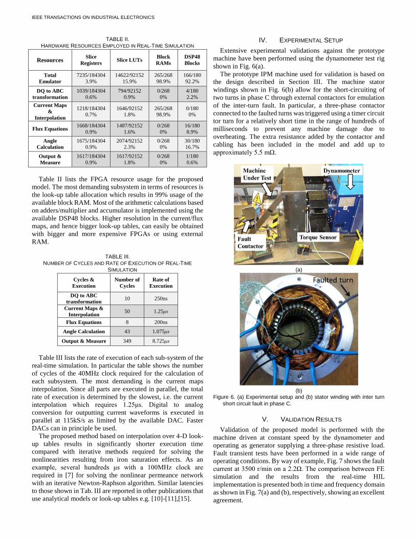
Validation of the proposed model is performed with the machine driven at constant speed by the dynamometer and operating as generator supplying a three-phase resistive load. Fault transient tests have been performed in a wide range of operating conditions. By way of example, Fig. 7 shows the fault current at 3500 r/min on a 2.2っ. The comparison between FE simulation and the results from the real-time HIL implementation is presented both in time and frequency domain as shown in Fig. 7(a) and (b), respectively, showing an excellent agreement.
IEEE TRANSACTIONS ON INDUSTRIAL ELECTRONICS
(a)
(b)
Figure 7. Transient (a) time domain comparison of FEA and HIL fault currents and, (b) FFT comparison at 3500 r/min and 2.2っ load.
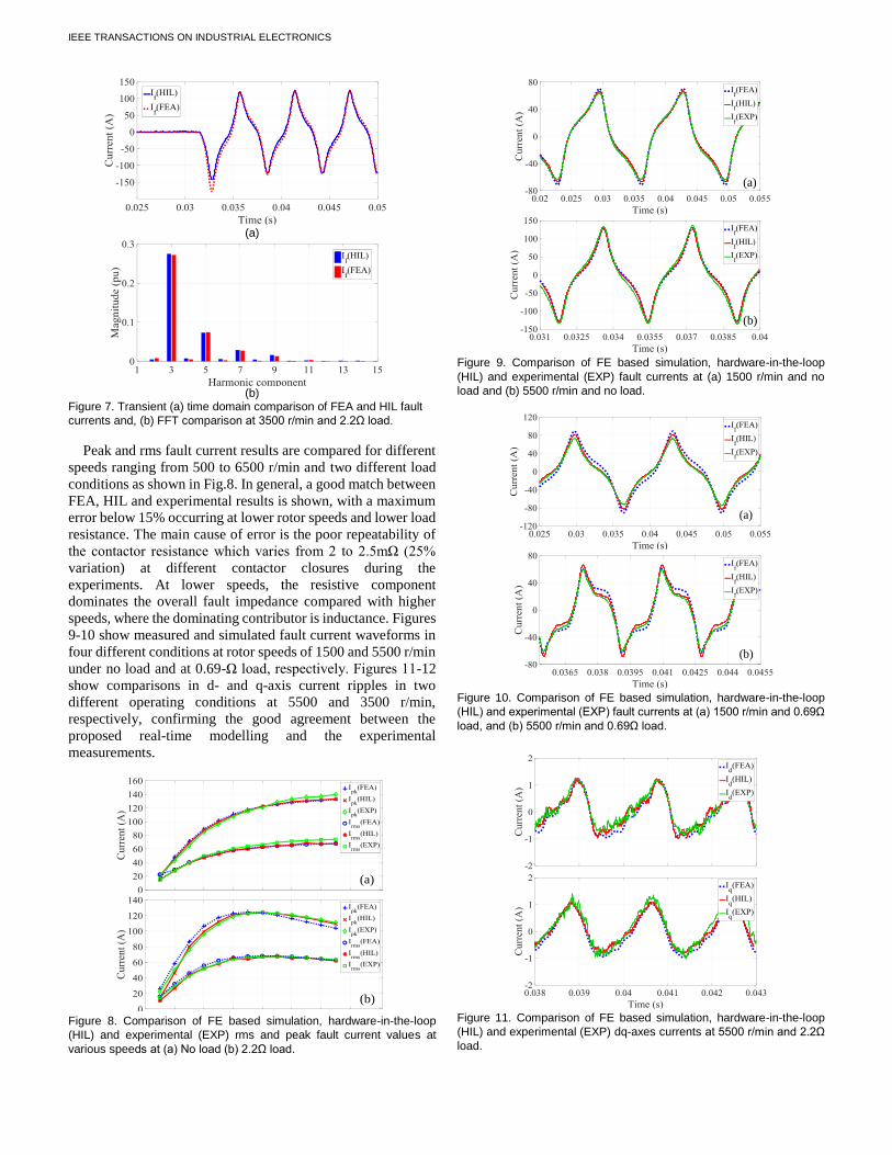
Peak and rms fault current results are compared for different speeds ranging from 500 to 6500 r/min and two different load conditions as shown in Fig.8. In general, a good match between FEA, HIL and experimental results is shown, with a maximum error below 15% occurring at lower rotor speeds and lower load resistance. The main cause of error is the poor repeatability of the contactor resistance which varies from 2 to 2.5mっ (25% variation) at different contactor closures during the experiments. At lower speeds, the resistive component dominates the overall fault impedance compared with higher speeds, where the dominating contributor is inductance. Figures 9-10 show measured and simulated fault current waveforms in four different conditions at rotor speeds of 1500 and 5500 r/min under no load and at 0.69-っ load, respectively. Figures 11-12 show comparisons in d- and q-axis current ripples in two different operating conditions at 5500 and 3500 r/min, respectively, confirming the good agreement between the proposed real-time modelling and the experimental measurements.
Figure 8. Comparison of FE based simulation, hardware-in-the-loop (HIL) and experimental (EXP) rms and peak fault current values at various speeds at (a) No load (b) 2.2っ load.
Figure 9. Comparison of FE based simulation, hardware-in-the-loop (HIL) and experimental (EXP) fault currents at (a) 1500 r/min and no load and (b) 5500 r/min and no load.
Figure 10. Comparison of FE based simulation, hardware-in-the-loop (HIL) and experimental (EXP) fault currents at (a) 1500 r/min and 0.69っ load, and (b) 5500 r/min and 0.69っ load.
Figure 11. Comparison of FE based simulation, hardware-in-the-loop (HIL) and experimental (EXP) dq-axes currents at 5500 r/min and 2.2っ load.
(a)
(b)
(a)
(b)
(a)
(b)
IEEE TRANSACTIONS ON INDUSTRIAL ELECTRONICS
Figure 12. Comparison of FE based simulation, hardware-in-the-loop (HIL) and experimental (EXP) dq-axes currents at 3500 r/min and 2.2っ load.
VI. APPLICATION
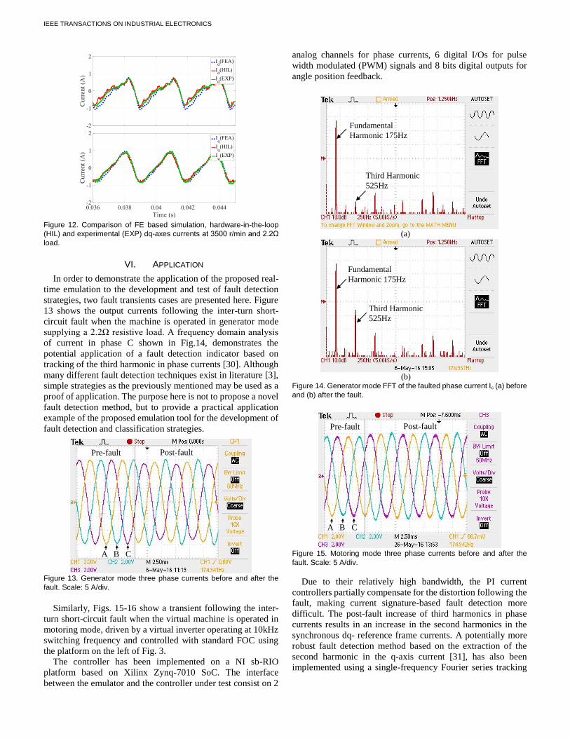
In order to demonstrate the application of the proposed real-time emulation to the development and test of fault detection strategies, two fault transients cases are presented here. Figure 13 shows the output currents following the inter-turn short-circuit fault when the machine is operated in generator mode supplying a 2.2っ resistive load. A frequency domain analysis of current in phase C shown in Fig.14, demonstrates the potential application of a fault detection indicator based on tracking of the third harmonic in phase currents [30]. Although many different fault detection techniques exist in literature [3], simple strategies as the previously mentioned may be used as a proof of application. The purpose here is not to propose a novel fault detection method, but to provide a practical application example of the proposed emulation tool for the development of fault detection and classification strategies.
Figure 13. Generator mode three phase currents before and after the fault. Scale: 5 A/div.
Similarly, Figs. 15-16 show a transient following the inter-
turn short-circuit fault when the virtual machine is operated in motoring mode, driven by a virtual inverter operating at 10kHz switching frequency and controlled with standard FOC using the platform on the left of Fig. 3.
The controller has been implemented on a NI sb-RIO platform based on Xilinx Zynq-7010 SoC. The interface between the emulator and the controller under test consist on 2
analog channels for phase currents, 6 digital I/Os for pulse width modulated (PWM) signals and 8 bits digital outputs for angle position feedback.
Figure 14. Generator mode FFT of the faulted phase current Ic (a) before and (b) after the fault.
Figure 15. Motoring mode three phase currents before and after the fault. Scale: 5 A/div.
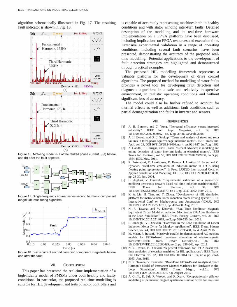
Due to their relatively high bandwidth, the PI current controllers partially compensate for the distortion following the fault, making current signature-based fault detection more difficult. The post-fault increase of third harmonics in phase currents results in an increase in the second harmonics in the synchronous dq- reference frame currents. A potentially more robust fault detection method based on the extraction of the second harmonic in the q-axis current [31], has also been implemented using a single-frequency Fourier series tracking
Pre-fault Post-fault
A B C
Fundamental Harmonic 175Hz
Third Harmonic 525Hz
Third Harmonic 525Hz
Fundamental Harmonic 175Hz
(a)
(b)
Pre-fault Post-fault
A B C
IEEE TRANSACTIONS ON INDUSTRIAL ELECTRONICS
algorithm schematically illustrated in Fig. 17. The resulting fault indicator is shown in Fig. 18.
Figure 16. Motoring mode FFT of the faulted phase current Ic (a) before and (b) after the fault appears.
Figure 17. Single-frequency Fourier series second harmonic component magnitude monitoring algorithm.
Figure 18. q-axis current second harmonic component magnitude before and after the fault.
VII. CONCLUSION
This paper has presented the real-time implementation of a high-fidelity model of PMSMs under both healthy and faulty conditions. In particular, the proposed real-time modelling is suitable for HIL development and tests of motor controllers and
is capable of accurately representing machines both in healthy conditions and with stator winding inter-turn faults. Detailed description of the modelling and its real-time hardware implementation on a FPGA platform have been discussed, including implications on FPGA resources and execution time. Extensive experimental validation in a range of operating conditions, including several fault scenarios, have been presented, demonstrating the accuracy of the proposed real-time modelling. Potential applications to the development of fault detection strategies are highlighted and demonstrated through practical examples.
The proposed HIL modelling framework represents a valuable platform for the development of drive control algorithms. The proposed method for modelling of stator faults provides a novel tool for developing fault detection and diagnostic algorithms in a safe and relatively inexpensive environment, in realistic operating conditions and without significant loss of accuracy.
The model could also be further refined to account for thermal effects as well as additional fault conditions such as partial demagnetization and faults in inverter and sensors.
VIII. REFERENCES [1] A. H. Bonnett, and C. Yung. “Increased efficiency versus increased
reliability”. IEEE Ind. Appl. Magazine, vol. 14, DOI 10/1109/MIA.2007.909802, no. 1, pp. 29-36, Jan/Feb. 2008.
[2] A. H. Bonett, and G. C. Soukup. “Cause and analysis of stator and rotor failures in three-phase squirrel-cage induction motor”. IEEE Trans. Ind. Appl, vol. 28, DOI 10/1109/28.148460, no. 4, pp. 921-927, Jul/Aug. 1992.
[3] A. Gandhi, T. Corrigan, and L. Parsa. “Recent advances in modeling and online detection of stator interturn faults in electrical motors”. IEEE Trans. Ind. Electron., vol. 58, DOI 10/1109/TIE.2010.2089937, no. 5, pp. 1564-1575, May. 2011.
[4] R. Jastrzebski, O. Laakkonen, K. Rauma, J. Luukko, H. Saren, and O. Pyhonen. “Real-time emulation of induction motor in FPGA using floating point representation”. In Proc. IASTED International Conf. on Applied Simulation and Modelling, DOI 10/1109/IECON.2008.4758331, pp. 28-30, Jun. 2004.
[5] B. Asghari, V. Dinavahi "Experimental validation of a geometrical nonlinear permeance network based real-time induction machine model". IEEE Trans. Ind. Electron., vol. 59, DOI 10/1109/PESGM.2012.6344579, no 11, pp. 4049-4062, Nov. 2012.
[6] K. A. Liu, H. Tian, and Y. Zhang. “Development of HIL simulation platform for metro vehicle linear induction motor driving system”. IEEE International Conf. on Mechatronics and Automation (ICMA) , DOI 10/1109/ICMA.2015.7237519, pp. 403-408, Aug. 2015.
[7] N. R. Tavana, and V. Dinavahi. “Real-Time Nonlinear Magnetic Equivalent Circuit Model of Induction Machine on FPGA for Hardware-in-the-Loop Simulation”, IEEE Trans. Energy Convers. vol. 31, DOI 10/1109/TEC.2015.2514099, no 2, pp. 520-530, Jun. 2016.
[8] B. Jandaghi, V. Dinavahi. “Hardware-in-the-Loop Emulation of Linear Induction Motor Drive for MagLev Application”. IEEE Trans. Plasma Science, vol. 44, DOI 10/1109/TPS.2016.2535460, no. 4, April. 2016.
[9] M. Matar, R. Iravani. “Massively parallel implementation of AC machine models for FPGA-based real-time simulation of electromagnetic transients”. IEEE Trans. Power Delivery, vol. 26, DOI 10/1109/TPWRD.2010.2086499, no. 2, pp. 830-840, Apr. 2011.
[10] N. R. Tavana, V. Dinavahi. “A general framework for FPGA-based real-time emulation of electrical machines for HIL applications”. IEEE Trans. Ind. Electron., vol. 62, DOI 10/1109/TIE.2014.2361314, no 4, pp. 2041-2053, Apr. 2015.
[11] N. R. Tavana, V. Dinavahi. “Real-Time FPGA-Based Analytical Space Harmonic Model of Permanent Magnet Machines for Hardware-in-the-Loop Simulation”. IEEE Trans. Magn., vol.51, DOI 10/1109/TMAG.2015.2413376, n.8, August 2015.
[12] A. Griffo, D. Salt, R. Wrobel, and D. Drury. “Computationally efficient modelling of permanent magnet synchronous motor drives for real-time
Fundamental Harmonic 175Hz
Third Harmonic 525Hz
Third Harmonic 525Hz
Fundamental Harmonic 175Hz
(a)
(b)
++権貸怠
xIq
sin(2し)
++権貸怠
xcos(2し)
権貸痛_
f
x
権貸痛x
券態+券態 券 Mg 2nd
_

IEEE TRANSACTIONS ON INDUSTRIAL ELECTRONICS
Hardware-in-the-Loop simulation”. In Proc. 39th Annu. Conf. of the IEEE IES, DOI 10/1109/IECON.2013.6700009, pp. 5368-5373, Nov. 2013.
[13] C. Dufour, S. Abourida, J. Bélanger, and V. Lapointe. “Real-time simulation of permanent magnet motor drive on FPGA chip for high-bandwidth controller tests and validation”. In Proc. 32nd Annu. Conf. IEEE IECON, DOI 10/1109/IECON.2006.347676, pp. 4581-4586, Nov. 2006.
[14] C. Dufour, J. Bélanger, S. Abourida, and V. Lapointe. “FPGA-based real-time simulation of finite-element analysis permanent magnet synchronous machine drives”. In Proc. Conf. IEEE PESC, DOI 10/1109/PESC.2007.4342109, pp. 909-915, Jun. 2007.
[15] C. Dufour, S. Cense, T. Yamada, R. Imamura, and J. Bélanger. “FPGA permanent magnet synchronous motor floating-point models with variable-DQ and spatial harmonic Finite-Element Analysis solvers”. In Proc. 15th Conf. IEEE EPE/PEMC, DOI 10/1109/EPEPEMC.2012.6397490, pp. LS6b-2, Sep. 2012.
[16] A. Hasanzadeh, C. S. Edrington, N. Stroupe, and T. Bevis. “Real-time emulation of a high-speed microturbine permanent-magnet synchronous generator using multiplatform hardware-in-the-loop realization”. IEEE Trans Ind. Electron. vol. 61, DOI 10/1109/TIE.2013.2279128, no. 6, pp. 3109-3118, Jun. 2014.
[17] J. A. Walker, D. G. Dorrell, and C. Cossar. “Flux-linkage calculation in permanent-magnet motors using the frozen permeability method”. IEEE Trans. Magn., vol. 41, DOI 10/1109/TMAG.2005.854973, no. 10, pp. 3946-3948, Oct. 2005.
[18] W. Q. Chu, and Z. Q. Zhu. “Average torque separation in permanent magnet synchronous machines using frozen permeability”. IEEE Trans. Magn., vol. 49, DOI 10/1109/TMAG.2012.2225068, no. 3, pp. 1202-1210, Mar. 2013.
[19] Z. Ling, L. Zhou, S. Guo, and Y. Zhang. “Equivalent circuit parameters calculation of induction motor by finite element analysis”. IEEE Trans. Magn., vol. 50, DOI 10/1109/TMAG.2013.2282185, no. 2, pp. 833-836, Feb. 2014.
[20] F. Alvarez-Gonzalez, A. Griffo. “High-Fidelity Modelling of Permanent Magnet Synchronous Motors for Real-Time Hardware-in-the-Loop Simulation”. In Proc. 9th IET Conf. PEMD. DOI 10/1049/cp.2016.0308, Apr. 2016.
[21] A. Schmitt, J. Richter, U. Jurkewitz, and M. Braun. “FPGA-based real-time simulation of nonlinear permanent magnet synchronous machines for power hardware-in-the-loop emulation systems”. In Proc. 40th Annu. Conf. IEEE IES. DOI 10/1109/IECON.2014.7049060, Oct/Nov. 2014.
[22] C. Gerada, K. Bradley, and M. Summer. “Winding turn-to-turn faults in permanent magnet synchronous machine drives”. In Conf. Records 40th IAS Annu. Meeting. vol. 2, DOI 10/1109/IAS.2005.1518481, pp. 1029-1036, Oct. 2005.
[23] N. Leboeuf, T. Boileau, B. Nahid-Mobarakeh, N. Takorabet, F. Meibody-Tabar, and G. Clerc. “Inductance calculations in permanent-magnet motors under fault conditions”. IEEE Trans. Magn. vol. 48, DOI 10/1109/TMAG.2012.2197402, no. 10, pp. 2605-2616, Oct. 2012.
[24] L. Romeral, J. C. Urresty, J. R. Riba, and A. Garcia. “Modeling of surface-mounted permanent magnet synchronous motors with stator winding interturn faults”. IEEE Trans. Ind. Electron., vol. 58, DOI 10/1109/TIE.2010.2062480, no. 5, pp. 1576-1585, May. 2011.
[25] O. A. Mohammed, Z. Liu, S. Liu, and N. Y. Abed. “Internal short circuit fault diagnosis for PM machines using FE-based phase variable model and wavelets analysis”. IEEE Trans. Magn., vol. 43, DOI 10/1109/TMAG.2006.892301, no. 4, pp. 1729-1732, Apr. 2007.
[26] X. Chen, J. Wang, B. Sen, P. Lazari, and T. Sun. “A High-Fidelity and Computationally Efficient Model for Interior Permanent-Magnet Machines Considering the Magnetic Saturation, Spatial Harmonics, and Iron Loss Effect”. IEEE Trans Ind. Electron. vol. 62, DOI 10/1109/TIE.2014.2388200, no. 7, pp. 4044-4055, Jul. 2015.
[27] B. Sen, J. Wang, and P. Lazari. “A High Fidelity, Computationally Efficient Transient Model of Interior Permanent Magnet Machine with Stator Turn Fault”. IEEE Trans. Ind. Electron. vol. 63, DOI 10/1109/TIE.2015.2491884, no. 2, Feb. 2016.
[28] X. Chen, J. Wang, and A. Griffo. “A High-Fidelity and Computationally Efficient Electro-thermally Coupled Model for Interior Permanent-Magnet Machines in Electric Vehicle Traction Applications”. IEEE Trans. Transport. Electrific., vol. 1, DOI 10/1109/TTE.2015.2478257, no. 4, Dec. 2015.
[29] L. Wang, J. Jatskevich, and H. Dommel, “Re-examination of synchronous machine modeling techniques for electromagnetic transient simulations”,
IEEE Trans. Power Syst., vol. 22, DOI 10/1109/TPWRS.2007.901308, no. 3, pp. 1221–1230, Aug. 2007.
[30] J. C. Urresty, J. R. Riba, and L. Romeral. “Diagnosis of interturn faults in PMSMs operating under nonstationary conditions by applying order tracking filtering”. IEEE Trans. Power Electron., vol. 28, DOI 10/1109/TPEL.2012.2198077, no. 1, pp. 507-515, Jan. 2013.
[31] K.-H. Kim, B.-G. Gu, and I.-S. Jung. “Online fault-detecting scheme of an inverter-fed permanent magnet synchronous motor under stator winding shorted turn and inverter switch open”. IET electric power applications, vol. 5, DOI 10/1049/iet-epa.2010.0272, no. 6, pp. 529-539, Jul. 2011.
Fernando Alvarez-Gonzalez (S’16) received the B.Eng. and M.Eng. degrees from the University of Oviedo, Asturias, Spain, in 2012 and 2014, respectively. He is currently working toward the Ph.D. degree at The University of Sheffield, Sheffield, U.K. His current research interest include modelling, fault detection and Hardware-in-the-Loop simulation of permanent magnet motors for traction applications. Antonio Griffo (M’13) received the M.Sc. degree in electronic engineering and the Ph.D. degree in electrical engineering from the University of Napoli “Federico II,” Naples, Italy, in 2003 and 2007, respectively. From 2007 to 2013, he was a Research Associate with the University of Sheffield, Sheffield, U.K., and the University of Bristol, Bristol, U.K. He is currently a Lecturer with the Department of Electronic and Electrical Engineering, University of Sheffield. His research
interests include modeling, control and condition monitoring of electric power systems, power electronics converters, and electrical motor drives, for renewable energy, automotive and aerospace applications.
Bhaskar Sen (M’17) received his B.E. degree from Delhi College of Engineering, Delhi, India in 2003, M.Tech. degree from Indian Institute of Technology, Kanpur, India in 2006, both in electrical engineering and Ph.D. degree in electrical and electronic engineering from the University of Sheffield, UK in 2015. From 2006 to 2011, he worked as a research engineer with GE Global Research, Bangalore, India. Currently he is working as a research associate in the
University of Sheffield, UK. His current research interests include electrical machine fault modelling, machine fault detection and fault tolerant drives.
Jiabin Wang (SM’03) received the B.Eng. and M.Eng. degrees from Jiangsu University, Zhengjiang, China, in 1982 and 1986, respectively, and the Ph.D. degree from the University of East London, London, U.K., in 1996, all in electrical and electronic engineering.
Currently, he is a Professor in Electrical Engineering at the University of Sheffield, Sheffield, U.K. From 1986 to 1991, he was with the Department of Electrical Engineering at Jiangsu University, where he was appointed a Lecturer in 1987 and an Associated Professor in
1990. He was a Postdoctoral Research Associate at the University of Sheffield, Sheffield, U.K., from 1996 to 1997, and a Senior Lecturer at the University of East London from 1998 to 2001. His research interests range from motion control and electromechanical energy conversion to electric drives for applications in automotive, renewable energy, household appliances and aerospace sectors. He is a fellow of the IET and a senior member of IEEE.