Real-Time Communication in Wireless Ad-hoc Networks The RT...
208
PhD Thesis Real-Time Communication in Wireless Ad-hoc Networks The RT-WMP Protocol Danilo Tardioli October 2010 Supervisor: Jos´ e Luis Villarroel Salcedo Grupo de Rob ´ otica, Percepci ´ on y Tiempo Real (RoPeRT) Instituto de Investigaci´ on en Ingenier´ ıa de Arag ´ on (I3A) Departamento de Inform´ atica e Ingenier´ ıa de Sistemas (DIIS) Centro Polit´ ecnico Superior - Universidad de Zaragoza
Transcript of Real-Time Communication in Wireless Ad-hoc Networks The RT...

PhD Thesis
Real-Time Communication inWireless Ad-hoc Networks
The RT-WMP Protocol
Danilo Tardioli
October 2010
Supervisor: Jose Luis Villarroel Salcedo
Grupo de Robotica, Percepcion y Tiempo Real (RoPeRT)Instituto de Investigacion en Ingenierıa de Aragon (I3A)
Departamento de Informatica e Ingenierıa de Sistemas (DIIS)Centro Politecnico Superior - Universidad de Zaragoza

PhD Thesis
Real-Time Communication inWireless Ad-hoc Networks
The RT-WMP Protocol
Danilo Tardioli
October 2010
Supervisor
Jose Luis Villarroel Salcedo Universidad de Zaragoza
Jury
Luis Montano Gella Universidad de ZaragozaCarlos Sagues Blazquiz Universidad de ZaragozaLuis Almeida Universidade do Porto, PortugalMichael Gonzalez Harbour Universidad de CantabriaDaniele Trinchero Politecnico di Torino, Italy
Jose Marıa Drake Moyano Universidad de CantabriaAlejandro Antonio Alonso Munoz Universidad Politecnica de Madrid
European Reviewers
Antonio Paulo Gomes Mendes Moreira Universidade do Porto, PortugalTullio Facchinetti Universita di Pavia, Italy


Ai miei genitori.
i

ii

Trust that little voice in your head that says ”Wouldn’t it be interesting if..”And then do it.
Duane Michals
iii

iv
Agradecimientos
He tardado mucho en escribir estas lıneas, de hecho lo he dejado para el ultimomomento pero sigue siendo la parte quizas mas importante de esta tesis. Ante todome gustarıa dar las gracias a mis padres y hermanos que siempre me han apoyadoen mis decisiones aun siendo estas dificiles para mi y para ellos. La distanciaamplifica muchas cosas y permite apreciar mucho mas lo que no tienes cerca.
Otro gran agradecimiento va para mi director Jose Luis que a lo largo de estosanos me ha ensenado muchısimas cosas y no solo en lo profesional sino tambienen lo personal. Tampoco olvido todos los otros miembro del grupo de Roboticay del Departamento, en particular Luis Montano y Carlos Sagues, con los cualestantas salidas en “furgoneta” hemos compartido.
Desde luego no olvido al prof. Luis Almeida que me ha dado la posibilidad depasar tres meses fantasticos en Oporto, de donde he vuelto con una maleta masllena de conocimientos, pero sobre todo con un buen amigo y companero.
Ni tampoco podrıa olvidar todos los amigos que me han estado cerca en estetiempo: Domenico, Luis, Alex, Ana Cris, Darıo, Izaskun, Eva, Marta, Alberto,Pablo, Javier, Eduardo, Oscar y muchos mas que me han ayudado y dado animoen los momentos dificiles tanto relacionados con el trabajo como no, especial-mente en este ultimo ano y por supuesto a Maria Francesca que me ha soportadodurante tantos anos, parte de esta tesis es suya.
Finalmente me gustarıa agradecer a Francesca que sin embargo me soporta ahoraen los momento sin duda mas dificiles y que me da cada dıa la tranquilidad paracontinuar avanzando.
v

vi
Project Framework
This thesis has been developed with the Robotics, Perception and Real Time Groupof the University of Zaragoza, in the framework of the national projects EXPRES(DPI2003-07986), NERO (DPI2006-07928), TESSEO (DPI 2009-08126) and ofthe European Commission project URUS (EC IST-1-045062-URUS-STP). Herefollows a short description of the cited projects in chronological order:
• EXPRES - Automated Exploration Techniques For Rescue Applications
The main project objective is the research in exploration strategies: a set ofperception-action techniques that allow to obtain environment information,to plan motions for refining and completing this information (active percep-tion), and to perform safe robot motions in non-structured scenarios. In re-cent years, these techniques have been greatly improved and have been ap-plied in indoor environments with very good results. The goal of this projectis to further develop these techniques to apply them to novel problems andmore difficult scenarios, like rescue operations.
• NERO - NEtworked RObots
The complex nature of mobile robot tasks leads to the necessity of systemswith several coordinated robots (agents) working in cooperation. Some in-ternational directives refer to robotic elements connected to the communi-cation nets or wireless nets including the robots themselves and the sensorsdistributed in the working place (static agents) exchanging and sharing in-formation. This concept is extended to robot interactions between humans,the sensors and the environment. We propose this project which is very re-lated with previous MEC projects obtained by this research team, to continueworking on subjects related to multi-robot cooperation techniques, computervision, robot vision for motion and communications.
• URUS - Ubiquitous Networking Robotics in Urban Settings
European cities are becoming difficult places to live due to noise, pollutionand security. Moreover, the average age of people living European cities is
vii

growing and in a short period of time there will be an important communityof elderly people. City Halls are becoming conscious of this problem and arestudying solutions, for example by reducing the free car circulation areas.Free car areas imply a revolution in the planning of urban settings, for ex-ample, by imposing new means for transportation of goods, security issues,etc. In this project we want to analyse and test the idea of incorporating anetwork of robots (robots, intelligent sensors, devices and communications)in order to improve life quality in such urban areas.
• TESSEO - TEams of robots for Service and Security missiOns
The project proposes to investigate techniques for a multi-robot team to actin coordination in realistic scenarios. For the deployment, it is necessary todeal with algorithms and methods related to task planning and allocation, co-ordinated navigation planning, environment perception from multiple viewsprovided by every member of the team, while the communication connec-tivity among all the elements of the system is maintained – robots, infras-tructure, supervisor team, etc. Although some of the techniques involved areusually proposed in the literature and in many projects somehow indepen-dently, the research in this project will also be oriented to develop techniquesintegrating the different subjects involved. Only in this way it will be pos-sible to develop realistic applications using systems with autonomous andsupervised behaviours.
This thesis was partially financed by the PhD scholarship provided by the AragonGovernment (FPI-B093/2006). The thesis author belongs to the Instituto de Inves-tigacion en Ingenierıa de Aragon (I3A).
Some results in this thesis were outcome of a research visits to the laboratory of theDepartamento de Engenharia Electrotecnica e de Computadores of the Faculdadede Engenharia da Universidad do Porto, Portugal (April - July 2009). This researchstay was supported by the mobility scholarship for PhD students to obtain theEuropean Doctorate Mention and financed by the Spanish Ministry of Educationfor the academic year 2008-2009 (TME2008-01132).
viii
Resumen
Las redes moviles ad-hoc (MANET) han ido ganando popularidad en los ultimosanos gracias a su facilidad de despliegue y el bajo coste de sus componentes.En una red ad-hoc de hecho no son necesarias estaciones base cableadas ni in-fraestructuras dado que los nodos se comunican directamente mediante paquetesradio. En las redes ad-hoc, los protocolos de enrutamiento tienen el reto de es-tablecer y mantener las rutas multi-salto para garantizar la movilidad teniendo encuenta las limitaciones de ancho de banda y de potencia.
Por otro lado, junto con el crecimiento de Internet, se estan difundiendo aplica-ciones como videoconferencia o similares que requieren soporte para trafico conCalidad de Servicio (QoS). Hay, sin embargo, situaciones en las que las garantıasde QoS no es suficiente. Este es el caso de los sistemas que requieren una garantıamas fuerte en la entrega de los mensajes como por ejemplo los sistemas de tiemporeal donde la perdida o la llegada tardıa de un dato puede provocar serios prob-lemas. Estas nuevas necesidades dificultan aun mas los ya difıciles problemas deofrecer comunicacion inalambrica entre estaciones moviles pertenecientes a unaMANET.
En esta tesis doctoral, se propone una plataforma completa que trata de hacerfrente a todos estos problemas. Proponemos un protocolo inalambrico en tiemporeal para MANET capaz de garantizar tiempos de entrega acotados y conocidostanto para datos unicast como multicast.
Ademas, esta plataforma ofrece soporte para transporte de datos con Calidad deServicio junto con el trafico de tiempo real sin interferir ni empeorar las carac-terısticas temporizaciones de este ultimo.
La entrega de los mensajes esta basada en prioridades que son fijas para el traficode tiempo real y variables en caso de trafico con Calidad de Servicio. Por diseno,es capaz de comunicaciones multisalto independientemente de la topologıa de lared e incluye una tecnica para reducir la influencia del trafico ajeno y la cantidadde errores en el caso de tener que compartir el dominio de colision con otras redes.
ix

Se ha disenado para trabajar sobre el protocolo IEEE 802.11 sin necesidad demodificaciones de hardware. Se ha concebido principalmente para ofrecer comu-nicacion inalambrica en tiempo real en pequenos equipos de robots haciendo posi-ble el intercambio de informacion como datos cinematicos o laser. Este aspecto esde hecho a menudo descuidado, mientras que es uno de los temas mas importantesen la robotica cooperativa. Su validez ha sido demostrada en varios experimentosreales y aplicaciones que incluyen el mantenimiento de la conectividad, ası comolas comunicaciones subterraneas.
x
Abstract
Mobile Ad-hoc NETworks (MANETs) have been gaining increasing popularity inrecent years thanks to their ease of deployment and the low cost of its components.No wired base station or infrastructure is needed since each host communicatesone another via radio packets. In ad-hoc networks, routing protocols are chal-lenged with establishing and maintaining multi-hop routes in the face of mobility,bandwidth limitation and power constraints.
However, as the technology and popularity of Internet grows, applications such asvideo conferencing that require Quality of Service (QoS) support are becomingmore widespread. There are, however, situations in which guaranteeing a Qualityof Service is not enough. This is the case of systems that rely on the guaran-teed timely delivery of data as, for example, hard real-time systems where theloss or the late arrival of a single data can provoke serious issues. These new re-quirements, add difficulty to the already demanding problem of offering wirelesscommunication among mobile stations belonging to a MANET.
In this PhD thesis, we propose a complete platform that tries to cope with allthese problems. We propose a real-time wireless protocol for MANET capable oftimely delivering of both unicast and multicast data. In addition it offers Quality ofService data transport without interfering with worst-case real-time characteristics.This platform is able to manage message priority and is, by design, capable ofmulti-hop communications even in presence of foreign traffic and interference.
It has been designed to work on top of the IEEE 802.11 protocol without needinghardware modifications. It has been conceived mainly to offer real-time wirelesscommunication in small robot teams making possible the sharing of informationsuch a kinematics or laser data. This aspect is in fact often neglected while is oneof the most important issues in cooperative robotics. Its validity has been provedin several real experiments and applications including a connectivity enforcementframework as well as in underground communications.
xi

xii

Contents
List of Figures xix
List of Tables xxv
1 Introduction 11.1 Real-Time Systems . . . . . . . . . . . . . . . . . . . . . . . . . . . . . . . . 2
1.1.1 Distributed Real-Time Systems . . . . . . . . . . . . . . . . . . . . . 21.1.2 Real-time Communication Protocols . . . . . . . . . . . . . . . . . . . 31.1.3 Wireless Real-Time Communication Protocols . . . . . . . . . . . . . 31.1.4 Wireless Communication in Mobile Robotics . . . . . . . . . . . . . . 4
1.2 The 802.11 Protocol . . . . . . . . . . . . . . . . . . . . . . . . . . . . . . . . 51.2.1 IEEE 802.11 PCF . . . . . . . . . . . . . . . . . . . . . . . . . . . . . 51.2.2 IEEE 802.11 DCF . . . . . . . . . . . . . . . . . . . . . . . . . . . . 61.2.3 Limitation of the 802.11 for Robots Communication . . . . . . . . . . 7
1.3 Objective of the Thesis . . . . . . . . . . . . . . . . . . . . . . . . . . . . . . 81.4 Structure of the Thesis . . . . . . . . . . . . . . . . . . . . . . . . . . . . . . 9
2 The RT-WMP Protocol 112.1 Related Work . . . . . . . . . . . . . . . . . . . . . . . . . . . . . . . . . . . 122.2 Overview . . . . . . . . . . . . . . . . . . . . . . . . . . . . . . . . . . . . . 132.3 Frames Definition . . . . . . . . . . . . . . . . . . . . . . . . . . . . . . . . . 152.4 The Link Quality Matrix . . . . . . . . . . . . . . . . . . . . . . . . . . . . . 152.5 Phases of the Protocol . . . . . . . . . . . . . . . . . . . . . . . . . . . . . . . 16
2.5.1 Priority Arbitration Phase . . . . . . . . . . . . . . . . . . . . . . . . 162.5.2 Authorization Transmission Phase . . . . . . . . . . . . . . . . . . . . 172.5.3 Message Transmission Phase . . . . . . . . . . . . . . . . . . . . . . . 17
2.6 Mobility Management . . . . . . . . . . . . . . . . . . . . . . . . . . . . . . 182.6.1 LQM Actualization . . . . . . . . . . . . . . . . . . . . . . . . . . . . 18
xiii
CONTENTS
2.6.2 LQM Misalignment . . . . . . . . . . . . . . . . . . . . . . . . . . . 192.6.3 Specific LQM Elements Values . . . . . . . . . . . . . . . . . . . . . 192.6.4 LQM Initialization . . . . . . . . . . . . . . . . . . . . . . . . . . . . 20
2.7 Error Handling . . . . . . . . . . . . . . . . . . . . . . . . . . . . . . . . . . 202.7.1 Node Failure or Node Loss . . . . . . . . . . . . . . . . . . . . . . . . 212.7.2 Frame Duplication . . . . . . . . . . . . . . . . . . . . . . . . . . . . 222.7.3 Frame Retransmission . . . . . . . . . . . . . . . . . . . . . . . . . . 22
2.8 Real-Time Features . . . . . . . . . . . . . . . . . . . . . . . . . . . . . . . . 232.8.1 Phases Boundness . . . . . . . . . . . . . . . . . . . . . . . . . . . . 232.8.2 Timing and Bandwidth . . . . . . . . . . . . . . . . . . . . . . . . . . 242.8.3 Timing . . . . . . . . . . . . . . . . . . . . . . . . . . . . . . . . . . 252.8.4 Bandwidth . . . . . . . . . . . . . . . . . . . . . . . . . . . . . . . . 26
2.9 Performance Evaluation . . . . . . . . . . . . . . . . . . . . . . . . . . . . . . 282.9.1 Real-time Behavior . . . . . . . . . . . . . . . . . . . . . . . . . . . . 282.9.2 Throughput . . . . . . . . . . . . . . . . . . . . . . . . . . . . . . . . 29
2.10 Conclusions . . . . . . . . . . . . . . . . . . . . . . . . . . . . . . . . . . . . 30
3 Multicast Extension 333.1 Related Work . . . . . . . . . . . . . . . . . . . . . . . . . . . . . . . . . . . 343.2 The RT-WMP-PME Protocol . . . . . . . . . . . . . . . . . . . . . . . . . . . 34
3.2.1 Frames Modification . . . . . . . . . . . . . . . . . . . . . . . . . . . 353.2.2 The PME Operations . . . . . . . . . . . . . . . . . . . . . . . . . . . 363.2.3 Influence on RT-WMP Temporizations . . . . . . . . . . . . . . . . . 373.2.4 RT-WMP-PME Temporizations . . . . . . . . . . . . . . . . . . . . . 383.2.5 Unicast use of the PME . . . . . . . . . . . . . . . . . . . . . . . . . . 40
3.3 Experimental Results . . . . . . . . . . . . . . . . . . . . . . . . . . . . . . . 423.3.1 Experimental Scenario . . . . . . . . . . . . . . . . . . . . . . . . . . 423.3.2 Priority Management and Fairness of the PME . . . . . . . . . . . . . 423.3.3 Overhead Introduced to RT-WMP . . . . . . . . . . . . . . . . . . . . 433.3.4 Multicast Performance of the RT-WMP-PME . . . . . . . . . . . . . . 453.3.5 Comparison between RT-WMP and RT-WMP+ . . . . . . . . . . . . . 46
3.4 Conclusions . . . . . . . . . . . . . . . . . . . . . . . . . . . . . . . . . . . . 47
4 QoS Extension 494.1 Related Work . . . . . . . . . . . . . . . . . . . . . . . . . . . . . . . . . . . 504.2 Overview . . . . . . . . . . . . . . . . . . . . . . . . . . . . . . . . . . . . . 51
4.2.1 Worst-case in RT-WMP . . . . . . . . . . . . . . . . . . . . . . . . . 51
xiv
CONTENTS
4.2.2 Available Time . . . . . . . . . . . . . . . . . . . . . . . . . . . . . . 514.2.3 Protocol Overview . . . . . . . . . . . . . . . . . . . . . . . . . . . . 524.2.4 Frame Header Extension . . . . . . . . . . . . . . . . . . . . . . . . . 534.2.5 Phases of the Protocol . . . . . . . . . . . . . . . . . . . . . . . . . . 534.2.6 Message Priority Policy . . . . . . . . . . . . . . . . . . . . . . . . . 55
4.3 Flow Admission Control . . . . . . . . . . . . . . . . . . . . . . . . . . . . . 554.3.1 Available Resource Estimation . . . . . . . . . . . . . . . . . . . . . . 564.3.2 Principle of Operations . . . . . . . . . . . . . . . . . . . . . . . . . . 57
4.4 Evaluation . . . . . . . . . . . . . . . . . . . . . . . . . . . . . . . . . . . . . 584.4.1 Available Time . . . . . . . . . . . . . . . . . . . . . . . . . . . . . . 584.4.2 Message size and Traffic impact . . . . . . . . . . . . . . . . . . . . . 594.4.3 Fairness and Class Flow Priority . . . . . . . . . . . . . . . . . . . . . 604.4.4 Priority Policy . . . . . . . . . . . . . . . . . . . . . . . . . . . . . . 604.4.5 Real Scenario Experiments . . . . . . . . . . . . . . . . . . . . . . . . 61
4.5 Conclusions . . . . . . . . . . . . . . . . . . . . . . . . . . . . . . . . . . . . 62
5 Alien Traffic Endurance 635.1 Related Work . . . . . . . . . . . . . . . . . . . . . . . . . . . . . . . . . . . 645.2 Problem Statement and Solution . . . . . . . . . . . . . . . . . . . . . . . . . 65
5.2.1 Solution . . . . . . . . . . . . . . . . . . . . . . . . . . . . . . . . . . 655.3 Description of the Enhancement . . . . . . . . . . . . . . . . . . . . . . . . . 66
5.3.1 The Timeout Extension . . . . . . . . . . . . . . . . . . . . . . . . . . 665.3.2 Definition of the Timeout Window . . . . . . . . . . . . . . . . . . . . 68
5.4 Experimental Results . . . . . . . . . . . . . . . . . . . . . . . . . . . . . . . 685.4.1 Experiments Development . . . . . . . . . . . . . . . . . . . . . . . . 69
5.5 Conclusions . . . . . . . . . . . . . . . . . . . . . . . . . . . . . . . . . . . . 72
6 Network Connectivity Enforcement 756.1 Related work . . . . . . . . . . . . . . . . . . . . . . . . . . . . . . . . . . . 766.2 System Overview . . . . . . . . . . . . . . . . . . . . . . . . . . . . . . . . . 786.3 Cooperative Navigation Module . . . . . . . . . . . . . . . . . . . . . . . . . 80
6.3.1 Spring-Damper model . . . . . . . . . . . . . . . . . . . . . . . . . . 806.3.2 Setting up the Virtual Structure . . . . . . . . . . . . . . . . . . . . . . 83
6.4 Communication Module . . . . . . . . . . . . . . . . . . . . . . . . . . . . . 846.4.1 Specializing the RT-WMP . . . . . . . . . . . . . . . . . . . . . . . . 84
6.5 Multi-Task Allocation Module . . . . . . . . . . . . . . . . . . . . . . . . . . 856.5.1 The Allocation Algorithm . . . . . . . . . . . . . . . . . . . . . . . . 87
xv
CONTENTS
6.5.2 Allocation Strategies . . . . . . . . . . . . . . . . . . . . . . . . . . . 886.6 Temporization Issues . . . . . . . . . . . . . . . . . . . . . . . . . . . . . . . 886.7 System Evaluation . . . . . . . . . . . . . . . . . . . . . . . . . . . . . . . . 90
6.7.1 Communication and Cooperative Navigation Experiments . . . . . . . 906.7.2 Task Allocation Simulations . . . . . . . . . . . . . . . . . . . . . . . 946.7.3 Experiments with the Whole System . . . . . . . . . . . . . . . . . . . 96
6.8 Conclusions . . . . . . . . . . . . . . . . . . . . . . . . . . . . . . . . . . . . 98
7 RT-WMP in Confined Environments 1017.1 Related Work . . . . . . . . . . . . . . . . . . . . . . . . . . . . . . . . . . . 1017.2 Specialization of RT-WMP . . . . . . . . . . . . . . . . . . . . . . . . . . . . 103
7.2.1 Using the Minimum Spanning Tree . . . . . . . . . . . . . . . . . . . 1037.3 Evaluation . . . . . . . . . . . . . . . . . . . . . . . . . . . . . . . . . . . . . 104
7.3.1 Preliminary Tests . . . . . . . . . . . . . . . . . . . . . . . . . . . . . 1057.3.2 Real Experiment . . . . . . . . . . . . . . . . . . . . . . . . . . . . . 110
7.4 Conclusions . . . . . . . . . . . . . . . . . . . . . . . . . . . . . . . . . . . . 113
8 The wmpSniffer 1158.1 The wmpSniffer . . . . . . . . . . . . . . . . . . . . . . . . . . . . . . . . . . 116
8.1.1 Recording Window . . . . . . . . . . . . . . . . . . . . . . . . . . . . 1188.1.2 Statistics Window . . . . . . . . . . . . . . . . . . . . . . . . . . . . . 120
8.2 The wmpSniffer Internal structure . . . . . . . . . . . . . . . . . . . . . . . . 1208.3 Obtaining a Complete Dataset . . . . . . . . . . . . . . . . . . . . . . . . . . 1218.4 The wmpSniffer Solution . . . . . . . . . . . . . . . . . . . . . . . . . . . . . 123
8.4.1 Online Wireless and Ethernet Sniff . . . . . . . . . . . . . . . . . . . . 1238.4.2 Reinsertion of Lost Frames . . . . . . . . . . . . . . . . . . . . . . . . 1238.4.3 Offline Frame Merge . . . . . . . . . . . . . . . . . . . . . . . . . . . 1248.4.4 Time Setting . . . . . . . . . . . . . . . . . . . . . . . . . . . . . . . 127
8.5 Evaluation . . . . . . . . . . . . . . . . . . . . . . . . . . . . . . . . . . . . . 1288.6 Conclusions . . . . . . . . . . . . . . . . . . . . . . . . . . . . . . . . . . . . 129
Conclusions 131
Conclusiones 135
A RT-WMP Development 141A.1 General Considerations . . . . . . . . . . . . . . . . . . . . . . . . . . . . . . 141
A.1.1 Instructions Determinism . . . . . . . . . . . . . . . . . . . . . . . . . 141
xvi

CONTENTS
A.1.2 Code Maintenance . . . . . . . . . . . . . . . . . . . . . . . . . . . . 142A.2 Software Structure . . . . . . . . . . . . . . . . . . . . . . . . . . . . . . . . 143
A.2.1 The RT-WMP Core . . . . . . . . . . . . . . . . . . . . . . . . . . . . 143A.2.1.1 Code Units . . . . . . . . . . . . . . . . . . . . . . . . . . . 143
A.2.2 Medium Layer . . . . . . . . . . . . . . . . . . . . . . . . . . . . . . 144A.2.3 Frame Compress/Decompress . . . . . . . . . . . . . . . . . . . . . . 145A.2.4 Low Level Communication . . . . . . . . . . . . . . . . . . . . . . . . 145A.2.5 Plugins . . . . . . . . . . . . . . . . . . . . . . . . . . . . . . . . . . 146
A.3 API . . . . . . . . . . . . . . . . . . . . . . . . . . . . . . . . . . . . . . . . 147A.4 Example of Application . . . . . . . . . . . . . . . . . . . . . . . . . . . . . . 148
B Field Experiments 153B.1 Robots Cooperation in Underground Environments . . . . . . . . . . . . . . . 154
B.1.1 Manzanera Tunnel, April, 7, 2006 . . . . . . . . . . . . . . . . . . . . 155B.1.2 Manzanera Tunnel, April, 16, 2006 . . . . . . . . . . . . . . . . . . . 155B.1.3 Manzanera Tunnel, July, 7, 2006 . . . . . . . . . . . . . . . . . . . . . 156B.1.4 Canfranc Tunnel, February, 27, 2009 . . . . . . . . . . . . . . . . . . . 157B.1.5 Canfranc Tunnel, March, 27, 2009 . . . . . . . . . . . . . . . . . . . . 157B.1.6 Canfranc Tunnel, May, 22, 2009 . . . . . . . . . . . . . . . . . . . . . 158
B.2 Multimedia in Confined Environments . . . . . . . . . . . . . . . . . . . . . . 158B.2.1 Canfranc Tunnel, May, 9, 2009 . . . . . . . . . . . . . . . . . . . . . . 159B.2.2 Canfranc Tunnel, September, 20, 2009 . . . . . . . . . . . . . . . . . . 159B.2.3 Canfranc Tunnel, January, 18, 2010 . . . . . . . . . . . . . . . . . . . 159
B.3 Surveillance . . . . . . . . . . . . . . . . . . . . . . . . . . . . . . . . . . . . 161B.4 Network connectivity . . . . . . . . . . . . . . . . . . . . . . . . . . . . . . . 161B.5 Cooperative Navigation and Localization . . . . . . . . . . . . . . . . . . . . 161
References 163
Abbreviations 177
xvii

CONTENTS
xviii
List of Figures
1.1 Backoff-based collision avoidance in 802.11 protocol . . . . . . . . . . . . . . 6
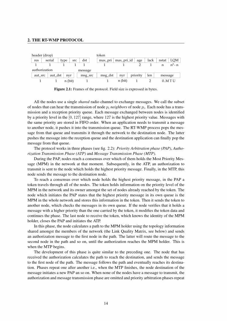
2.1 Frames of the protocol. Field size is expressed in bytes. . . . . . . . . . . . . . 14
2.2 A hypothetical situation described by the network graph and the correspondingLQM. The hops sequence of the protocol is also shown. . . . . . . . . . . . . . 16
2.3 Token duplication resolution mechanism. In case of message or authorizationduplication the mechanism works in a similar way. . . . . . . . . . . . . . . . 20
2.4 Worst case PAP situation. . . . . . . . . . . . . . . . . . . . . . . . . . . . . . 22
2.5 Timing of the protocol. . . . . . . . . . . . . . . . . . . . . . . . . . . . . . . 23
2.6 Comparison between RT-WMP and 802.11 for the worst-case situation. . . . . 26
2.7 Comparison between RT-WMP and 802.11 for the best-case situation. . . . . . 27
2.8 Priority behavior of the protocol. . . . . . . . . . . . . . . . . . . . . . . . . . 28
2.9 Fairness of the protocol. . . . . . . . . . . . . . . . . . . . . . . . . . . . . . 29
3.1 General frame of the RT-WMP-PME protocol. Other fields than mds are presentonly when multicast information is carried. . . . . . . . . . . . . . . . . . . . 36
3.2 Worst-case broadcast message delivery. . . . . . . . . . . . . . . . . . . . . . 38
3.3 Behavior of Rloop(wc) for different data rates. . . . . . . . . . . . . . . . . . . 39
3.4 Comparison between RT-WMP and RT-WMP+. . . . . . . . . . . . . . . . . . 41
3.5 End-to-end delivery delay for multicast messages. . . . . . . . . . . . . . . . . 43
3.6 Distribution of the wait time spent in transmission multicast queue. . . . . . . . 44
3.7 The RT-WMP worst-case bandwidth for 512 bytes unicast messages. . . . . . . 45
3.8 The RT-WMP-PME worst-case multicast bandwidth for 512 bytes unicast mes-sage. . . . . . . . . . . . . . . . . . . . . . . . . . . . . . . . . . . . . . . . . 46
3.9 Comparison between RT-WMP and RT-WMP+ in a 3-node, 1 Mbps network. . 47
3.10 Maximum Transmission Unit versus number of nodes. . . . . . . . . . . . . . 48
4.1 Time intervals used by the QoS Extension. . . . . . . . . . . . . . . . . . . . . 52
xix
LIST OF FIGURES
4.2 Frame of the RT-WMP with QoS extension. . . . . . . . . . . . . . . . . . . . 53
4.3 Resource estimation mechanism. . . . . . . . . . . . . . . . . . . . . . . . . . 56
4.4 Time spent for the RT-WMP in real test compared to worst-case for differenttopologies. . . . . . . . . . . . . . . . . . . . . . . . . . . . . . . . . . . . . . 57
4.5 QoS Cumulative Throughput vs. Message Size. . . . . . . . . . . . . . . . . . 58
4.6 QoS Cumulative Throughput vs. RT-WMP load percentile. . . . . . . . . . . . 59
4.7 End-to-end delay for different class (a) and same-class (b) flows. . . . . . . . . 60
4.8 PDR for different class (a) and same-class (b) flows. . . . . . . . . . . . . . . . 60
4.9 Delay and jitter vs hop count. . . . . . . . . . . . . . . . . . . . . . . . . . . . 61
4.10 A robot used in real experiments (a) in the Somport tunnel (b). . . . . . . . . . 62
5.1 Timeout expiration due to alien traffic. . . . . . . . . . . . . . . . . . . . . . . 67
5.2 Timeout extension due to alien traffic. . . . . . . . . . . . . . . . . . . . . . . 67
5.3 Influence of alien traffic on the amount of errors in the basic protocol. . . . . . 69
5.4 Error comparison for 64 B (a) 512 B (b) and 1000 B (c) alien frame size. . . . . 70
5.5 Loop Duration comparison. . . . . . . . . . . . . . . . . . . . . . . . . . . . . 71
5.6 Bandwidth comparison. . . . . . . . . . . . . . . . . . . . . . . . . . . . . . . 72
6.1 Modules and information flows. . . . . . . . . . . . . . . . . . . . . . . . . . 79
6.2 Spring-damper model to maintain connectivity and motion coordination. . . . . 80
6.3 Theoretical function of the radio signal versus the distance between the trans-mitter and the receiver. When the radio has a value less than the safety threshold(st), it enters the Controlled zone where the spring-damper analogy is used toavoid network disconnection. . . . . . . . . . . . . . . . . . . . . . . . . . . . 82
6.4 Spring-damper structure generated by the Prim-based algorithm with matrix oflinks generated for the minimum spanning tree. . . . . . . . . . . . . . . . . . 83
6.5 Example of a modified frame. All but the last field are used in the basic RT-WMP protocol. In the tail, kinematic information of the robots travels with theframe to reach all the nodes. . . . . . . . . . . . . . . . . . . . . . . . . . . . 85
xx
LIST OF FIGURES
6.6 Several task allocation related situations: •R1 andR2 are deadlocked by forcesin equilibrium. • Let us suppose a faulty allocation policy, with robots aban-doning their goal if an SDS is attached to them. R3 could attempt to reach G3,but once its SDS appears, the goal would be abandoned and R3 would move toR′3 due to the SDS pulling force. At R′3, the SDS is not needed anymore anddisappears, so G3 could be attempted again by R3. This cycle could repeat in-definitely. • Robots linked by SDSs in chain form (R4 and R5) have maximumreachability. • The resulting force of goal assignation and SDSs causes R7 andR8 to move toR′7 andR′8. At that point, one of the two is able to move forwardusing the other as a relay: a chain will have been formed. . . . . . . . . . . . . 86
6.7 Evolution of the robots movement and links created between them. . . . . . . . 90
6.8 Linear velocity during the simulation and evolution of the relative distancesbetween consecutive robots. . . . . . . . . . . . . . . . . . . . . . . . . . . . 90
6.9 Snapshots of the robots during the experiment. . . . . . . . . . . . . . . . . . . 91
6.10 Linear velocity and distance during the real experiment and evolution of therelative distances between consecutive robots. . . . . . . . . . . . . . . . . . . 92
6.11 Linear velocity and evolution of the γ(s) among robots during the link qualitybased real experiment. . . . . . . . . . . . . . . . . . . . . . . . . . . . . . . 92
6.12 Evolution of the link quality in an indoor environment. . . . . . . . . . . . . . 94
6.13 Snapshots of simulation runs for the allocation strategies. Solid lines link-ing robots indicate S-clusters, while dashed lines from robots to goals indicateassignations. Absent X in some snapshots are already visited goals. Hollowsquares are obstacles. In a) it can be seen that robots do not attempt to remainclose to one another, and only one task per robot is allocated. In b) can be seenthe complete MINMIX plans for each S-cluster. In c) can be seen the greedypairing P and how all the remaining allocated tasks are the closest ones to thetask in P . In d) can be seen the global TSP solution and how the first tasks init are assigned to S-clusters. . . . . . . . . . . . . . . . . . . . . . . . . . . . . 95
6.14 Data from task allocation simulations. a) Mission time. Boxplots show quar-tiles of the regular experiments. Stars and squares show the average of exper-iments without springs and with obstacles, respectively, for comparison. b)Preemption and S-cluster changes. Task preemptions and S-cluster changesover the full mission. c) Concurrency. The time histogram for one executionof each strategy in the medium range scenario. . . . . . . . . . . . . . . . . . . 96
xxi

LIST OF FIGURES
6.15 a) Paths followed by the robots and SDS at the time of their creation. b) γ ofthe links composing the Minimum Spanning Tree of the network during thecomplete experiment. c) Distances to base and between robots. . . . . . . . . 97
7.1 The environment. . . . . . . . . . . . . . . . . . . . . . . . . . . . . . . . . . 102
7.2 Alternative paths to reach the same node. . . . . . . . . . . . . . . . . . . . . 102
7.3 Asymmetrical behavior of links. . . . . . . . . . . . . . . . . . . . . . . . . . 103
7.4 An illustration of mobility scheme. . . . . . . . . . . . . . . . . . . . . . . . . 104
7.5 An illustration of the Somport tunnel. . . . . . . . . . . . . . . . . . . . . . . 105
7.6 RSSI and Delay Spread values sensed from receiver. . . . . . . . . . . . . . . 105
7.7 Relation between voice data and inter-arrival time. . . . . . . . . . . . . . . . 106
7.8 Distribution and raw data of Inter-Arrival Time (IAT) for two saturated flows. . 106
7.9 Distribution and raw data of Inter-Arrival Time (IAT). . . . . . . . . . . . . . . 107
7.10 End-to-end delay distribution. . . . . . . . . . . . . . . . . . . . . . . . . . . 108
7.11 RSSI and Prim based routing simulation. . . . . . . . . . . . . . . . . . . . . . 109
7.12 Identity of the last-hop sender. . . . . . . . . . . . . . . . . . . . . . . . . . . 110
7.13 Distribution and raw data of Inter-Arrival Time (IAT) in the real experiment. . . 111
7.14 Distribution of end-to-end delays in the real experiment. . . . . . . . . . . . . 112
7.15 Identity of the node that delivered the data packet to the mobile node and theRSSI value with which destination node has received the frame. . . . . . . . . 113
8.1 Some ethernet frames captured with wireshark. . . . . . . . . . . . . . . . . . 116
8.2 Main window of wmpSniffer. . . . . . . . . . . . . . . . . . . . . . . . . . . . 117
8.3 Recording window of wmpSniffer. . . . . . . . . . . . . . . . . . . . . . . . . 118
8.4 Statistic window of wmpSniffer. . . . . . . . . . . . . . . . . . . . . . . . . . 119
8.5 Graphics obtained with wmpSniffer. . . . . . . . . . . . . . . . . . . . . . . . 120
8.6 Internal structure of the wmpSniffer. . . . . . . . . . . . . . . . . . . . . . . . 121
8.7 FIFO buffer. Allows the collection of remote node information. Frames areindetified and matched by means of the hash value hx. . . . . . . . . . . . . . 122
8.8 Reinsertion of lost frames using serial field and heuristic. . . . . . . . . . . . . 124
8.9 Reinsertion of frames using hash frame and global ordering. . . . . . . . . . . 125
8.10 Recursive reinsertion using global ordering. . . . . . . . . . . . . . . . . . . . 126
8.11 Time set for the result set. . . . . . . . . . . . . . . . . . . . . . . . . . . . . . 127
8.12 Results of the fusion using the proposed technique over different topologiesand number of nodes. . . . . . . . . . . . . . . . . . . . . . . . . . . . . . . . 128
A.1 External structure of RT-WMP. . . . . . . . . . . . . . . . . . . . . . . . . . . 142
xxii

LIST OF FIGURES
A.2 Internal structure of RT-WMP. . . . . . . . . . . . . . . . . . . . . . . . . . . 143A.3 Attach Points. . . . . . . . . . . . . . . . . . . . . . . . . . . . . . . . . . . . 146
B.1 First test at Manzanera tunnel. . . . . . . . . . . . . . . . . . . . . . . . . . . 155B.2 Second test at Manzanera tunnel. . . . . . . . . . . . . . . . . . . . . . . . . . 156B.3 Third test at Manzanera tunnel. . . . . . . . . . . . . . . . . . . . . . . . . . . 156B.4 First test at Somport Tunnel. . . . . . . . . . . . . . . . . . . . . . . . . . . . 157B.5 Experiments at Canfranc tunnel. . . . . . . . . . . . . . . . . . . . . . . . . . 158B.6 Experiments at Canfranc tunnel on May 2009. . . . . . . . . . . . . . . . . . . 158B.7 Experiments at Somport Tunnel. . . . . . . . . . . . . . . . . . . . . . . . . . 159B.8 Experiments at Somport Tunnel on September 2009. . . . . . . . . . . . . . . 160B.9 Final test at Somport Tunnel. . . . . . . . . . . . . . . . . . . . . . . . . . . . 160B.10 Surveillance experiments at CPS car park. . . . . . . . . . . . . . . . . . . . . 161B.11 Final test at UPC. . . . . . . . . . . . . . . . . . . . . . . . . . . . . . . . . . 162
xxiii

LIST OF FIGURES
xxiv

List of Tables
2.1 Timing of the protocol for 11 Mbps data rate and message 512 bytes long.Times are expressed in ms. . . . . . . . . . . . . . . . . . . . . . . . . . . . . 24
2.2 Real end-to-end experiments results. Bandwidth (Mbps) and [delay] (ms). . . . 30
3.1 Worst-case RT-WMP unicast loop for 512 bytes unicast messages (ms). . . . . 443.2 Worst-case RT-WMP-PME unicast loop for 512 bytes multicast messages (ms). 453.3 Worst-case loop tloop(wc) (ms). R stands for RT-WMP while R+ for RT-WMP+. 46
5.1 Results. . . . . . . . . . . . . . . . . . . . . . . . . . . . . . . . . . . . . . . 73
7.1 Parameters and results of the experiment. . . . . . . . . . . . . . . . . . . . . 110
B.1 Chronological list of experiments. . . . . . . . . . . . . . . . . . . . . . . . . 154
xxv

LIST OF TABLES
xxvi
Chapter 1
Introduction
Mobile Ad-hoc NETworks (MANETs) have been gaining increasing popularity in recent yearsthanks to their ease of deployment and the low cost of their components. No wired base stationor infrastructure is needed since each host communicates one with another via radio packets. Inad hoc networks, routing protocols are challenged with establishing and maintaining multihoproutes in the face of mobility, bandwidth limitation and power constraints. Moreover, wirelesschannel bandwidth is limited. The scarce bandwidth decreases even further due to the effectsof multiple access, signal interference and channel fading. All these limitations and constraintsmake multihop network research more challenging.
Intense research activity in recent years has aimed at developing efficient, flexible andsecure communication platforms without the limitations that wired networks have in terms ofmobility.
Furthermore, as the technology and popularity of the Internet increases, applications suchas video conferencing, that require Quality of Service (QoS) support, are becoming morewidespread. Moreover, there are situations in which guaranteeing a Quality of Service is notenough. This is the case of systems that rely on the guaranteed timely delivery of data as, forexample, hard real-time systems where the loss or the late arrival of a single item of data canprovoke serious issues.
These new requirements add further difficulties to the already demanding problem of of-fering wireless communication among mobile stations belonging to a MANET.
In this PhD thesis, we propose a complete platform that tries to cope with all these prob-lems. We propose a real-time (RT) wireless protocol for MANET capable of delivering bothunicast and multicast data. It manages static and variable priorities and is, by design, capableof multi-hop communications. It has been designed to work on top of the IEEE 802.11 suite ofprotocols [IEEE97] without the need for hardware modifications.
The next section provides a brief introduction to real-time systems (both embedded anddistributed). Then a brief explanation of the 802.11 protocol and its inadequacy for transportingtime-sensitive data is given.
1

1. INTRODUCTION
1.1 Real-Time Systems
A real-time system is commonly defined as a computer system in which the correctness of thesystem depends not only on the logical result of computation (logical correctness), but also onthe times at which results are produced (timing correctness) [Ramamritham94]. This secondtype of correctness is normally expressed as a set of timing constraints that the system has tomeet at run-time. According to these constraints, real-time systems may be broadly classifiedinto two categories: hard and soft. Hard real-time systems require all their constraints to bemet under any circumstances, otherwise catastrophic results may occur. Many examples ofhard systems can be found within computer systems where a timing failure can cause an intol-erable cost (in terms of human lives, equipment damage or economic loss) such as automotive,avionics, robotic systems, nuclear or chemical plants, etc. As an example, consider the airbagin a car. It is not sufficient to establish that after a collision it will inflate. It is also crucial thatthis happens neither too early nor too late.
Soft real-time systems allow some of their constraints to be occasionally lost, producing adegradation of the system response [Barrena00]. A good example of a soft system is a multi-media application where not all the frames are required to be delivered or visualized to obtaina correct and sufficient quality of the output stream. Real-time systems rely, in general, ondedicated hardware (embedded systems) or on computers running real-time operating systemssuch as QNX [QNX], VxWorks [VXW] or even simpler ones such as MaRTE OS [Rivas01]or Free RT-OS [FRTOS]. This is due to the fact that all the parts involved in RT systemsmust be capable of offering timing guarantees. This includes hardware and also, in the case ofcomputer-based systems, processors. For example, it is impossible to use built-in cache mem-ory due to the unpredictable delay that a cache miss can provoke (even if some preliminarystudies to make it possible have already been carried out [Aparicio08]).
1.1.1 Distributed Real-Time Systems
Sometimes, however, real-time systems can not be constituted by a single processing unit. Thisis due to several reasons. The most common is the geographical distribution. Local real-timesystems process data in the proximity of heterogeneous sensors and communicate the resultsof the computation to a central processing unit. An example is the airplane where hundredsof real-time systems process the data from thousands of sensors all over the plane. Evidently,not all the sensors can be connected to the same processor. Again, often each sensor needsspecialized hardware that can not be concentrated in a single unit. On the other hand, real-timesystems can be divided into several subsystems to increment their fault-tolerance. In somesituations, in fact, if only one subsystem fails, the system can continue to operate althoughsometimes with a reduced set of functions.
However, in the decentralization of systems into subsystems or even in communicationamong peers, the global real-time characteristics must be maintained. Otherwise, differentnodes may learn of different events at different points in time (due to unpredictable communi-cation delays) causing some nodes to have an incorrect view of the environment or situation,just to give an example. They will act inconsistently and perhaps cause damage to life andproperty [Zuberi96].
2

1.1 Real-Time Systems
This means that the communication network is part of the real-time system and must beable to deal with timing issues. In other words, in distributed real-time systems, not only mustproper causal ordering be ensured, but message deadlines (defined as the instant of time bywhich the execution of a job is required to be completed [Liu00]) must be met as well, since ina typical distributed real-time system, the task of monitoring and controlling various aspects ofthe environment is divided among the nodes.
This requires that the real-time protocols must offer timing and bounded end-to-end deliv-ery delay guarantees. This requirement is translated to the need for a controlled and determin-istic access to the medium.
Unfortunately, the majority of common communication protocols do not take into accounttiming issues since they have been designed, in general, to offer high mean bandwidth. Evenif dedicated protocols do exist, they require specialized hardware. The next sections brieflyintroduce both dedicated protocols and the works that have tried to adapt commercial protocolsto enable them to support real-time traffic.
1.1.2 Real-time Communication Protocols
Several real-time communication protocols have been developed in recent decades, especiallyfor industrial and professional use. Some examples are the CAN bus [ISO93] (used principallyin vehicles), PROFIBUS [PBUS96] for field bus communication in automation technology orthe Factory Instrumentation Protocol (FIP) [FIP].
However, these types of protocol require, in general, special and dedicated hardware (net-work cards and cables).
The development of real-time protocols based on well-known commercial technologieshas been the subject of much research. Ethernet is the most widely used technology thanks toits low cost and widespread availability. Unfortunately, it is a non-deterministic protocol andcannot be used as is in real-time networks. To overcome this limitation, many solutions havebeen proposed [Pedreiras05]. Modified CSMA-based protocols change the behaviour of nativeEthernet CSMA/CD protocols to avoid collisions (Virtual Time CSMA Protocol [Molle85])or to sort them in a deterministic manner (Windows [Malcolm95], CSMA/DCR [Le Lann93],EquB [Sobrinho98]). Token-passing solutions make the access control deterministic allow-ing a single node (the token owner) to transmit at once (Timed-Token Protocol [Malcolm94],RETHER [Venkatramani94], RT-EP [Martınez05]). Another type of solution is based on theTDMA paradigm, in which disjointed time slots are assigned to nodes (TTP/C [Schwarz02],MARS [Kopetz89]). In addition, there are Master/Slave schemes in which a token master de-cides which node can transmit at any given moment (ETHERNET Powerlink [PWRLINK],FTT-Ethernet [Pedreiras03, Pedreiras02]). For further information, an exhaustive overview ofthe existing real-time communication protocols can be found in [Hanssen03] while a deeperanalisys of few of them in [Franchino10] .
1.1.3 Wireless Real-Time Communication Protocols
With the progressive introduction of wireless networks, many research projects have tried totransfer solutions for wired networks to the wireless medium. Indeed, token-passing, TDMA
3

1. INTRODUCTION
and Master/Slave solutions can be used almost without modification in a wireless environmentwhenever each node can reach all of the other nodes with a single hop. Modified CSMAtechniques, however, can not be used in a wireless environment because nodes can not listen tothe channel while they are transmitting. An overview of these protocols can be found in section2.1.
On the one hand, wireless networks are, in general, less reliable than wired ones, the prob-ability of errors being much higher. This is due to the possibility of interference (from mobilephones, microwave ovens, high voltage lines and so on) or simply to the distance betweenpeers. Moreover, the fact that nodes are not able to listen to the channel while transmittingaggravates the problem of collision detection and resolution. The vast majority of wirelessprotocols rely, in this aspect, on random backoff mechanisms that introduce a thick dose ofunpredictability into the Medium Access Control (MAC) layer. On the other hand, the need formulti-hop communication in some scenarios (battlefield or open field applications, rescue intunnels, etc.) causes other types of problems such as the need for efficient routing algorithmsor, above all, the reduction of the available bandwidth that has to be shared at least betweenstations in the same collision domain.
1.1.4 Wireless Communication in Mobile Robotics
Even though the communication aspect has been somewhat undervalued in recent years, it isespecially important in cooperative mobile robotics. Robots need to collaborate to achieve acommon goal. Sensors on robots produce periodic updates that must be transmitted to othermembers of the team respecting time constraints to enable such a collaboration [Stankovic04]and to be able to close the distributed perception-actuation loop in a correct manner. On the onehand this fact implies the need for real-time communications. On the other hand, robots in theteam need to move to complete the mission. From the point of view of the underlying networkthey can assume any type of topological configuration. The protocols for mobile robotics mustbe able to manage, in addition to real-time, mobility and multi-hop communication in order notto restrict the freedom of the team members.
Often, mobile robots are equipped with wireless network cards that enable them to commu-nicate with each other. In general they use cards based on the IEEE 802.11 suite of protocols.This is a set of standards carrying out wireless local area network (WLAN) computer commu-nication in the 2.4 and 5.2 GHz frequency bands. They have been created and are maintainedby the IEEE LAN/MAN Standards Committee (IEEE 802). The 802.11 family includes sev-eral over-the-air modulation techniques that use the same basic protocol. The most popularare those defined by the 802.11b and 802.11g protocols, which are amendments to the originalstandard. Usually these protocols are chosen thanks to the low cost of the devices, the rela-tively high bandwidth and the good coverage range. Unfortunately, these protocols do not relyon a deterministic MAC. Specifically, the IEEE 802.11 uses a random backoff mechanism formedium access and collision resolution. This makes the use of this solution impossible in areal-time network where all the phases of the communication are required to be time-bounded.Moreover, the protocol is not able to manage (natively) multi-hop peer-to-peer communicationand mobility is restricted to the collision domain shared by the members of the network.
In the next section a brief introduction to 802.11 is presented. The basic operation is shown
4
1.2 The 802.11 Protocol
both for the Point Coordination Function (PCF) and Distributed Function (DCF) together withthe limitation that this suite of protocols has to support and deliver time-sensitive data.
1.2 The 802.11 Protocol
The IEEE 802.11 has become the standard for wireless networking thanks to its wide diffusion.Its standardisation and the low price of the devices have been the key factors for its wide ac-ceptance. It regulates the over-the-air modulation techniques that use the same basic protocol.The most popular standards are those defined by the 802.11b and 802.11g protocols, whichare amendments to the original standard. The 802.11-1997 was the first wireless networkingstandard, but 802.11b was the first widely accepted one, followed by 802.11g and 802.11n.
The standard defines both physical and medium access control layers. There are threepossible physical layers, the infrared (IR), frequency hopping spread spectrum (FHSS) andDirect-sequence spread spectrum (DSSS). The latter is the most widely used and in fact, toour knowledge, it is only possible to find on the market devices that implement this type ofphysical layer. The MAC layer defines two medium access coordination mechanisms: PointCoordination Function (PCF) and Distributed Coordination Function (DCF).
With PCF, a point coordinator within the access point controls which stations can transmitduring any given period of time. It arbitrates, in fact, the access to the medium.
The IEEE 802.11 DCF is based, instead, on the Carrier Sense Multiple Access with Colli-sion Avoidance (CSMA/CA) mechanism which is similar to the Carrier Sense Multiple Accesswith Collision Detection (CSMA/CD) used in old Ethernet networks. In this scheme, stationscompete to gain the right to access the medium following a complex and non-deterministicinter-frame-delay prioritisation. The DCF supports both infrastructure communication, basedon Access Point (AP) that is used by stations to communicate with each other (stations sendframes to the AP and it repeats the frame to the destination station) and peer-to-peer commu-nication (called ad-hoc mode).
1.2.1 IEEE 802.11 PCF
The PFC is an optional method (that is, its implementation is not mandatory in 802.11 devices).It enables the transmission of time-sensitive information. With PCF, a point coordinator withinthe access point controls which stations can transmit during any given period of time. Withina time period called the contention free period, the point coordinator will step through allstations operating in PCF mode and poll them one at a time. If a station has something in itstransmission queue, it is authorized to transmit. During this time no other station can sendanything. The point coordinator will then poll the next station and continues down the pollinglist, while letting each station have a chance to send data.
Thus, PCF is a contention-free protocol and enables stations to transmit data frames syn-chronously, with regular time delays between data frame transmissions. This makes it possibleto more effectively support information flows, such as video and control mechanisms, havingstiffer synchronization requirements.
5

1. INTRODUCTION
DIFS
DIFS
DIFS DIFS
BackoffFrame + ack
pa
pb
pc
Figure 1.1: Backoff-based collision avoidance in 802.11 protocol
However, as an optional feature it is not used and, in practice, no devices implement thisscheme.
1.2.2 IEEE 802.11 DCF
The IEEE 802.11 DCF is based on the CSMA/CA mechanism. This mechanism, similar toCSMA/CD used in old Ethernet networks, is not so effective as its relative. In fact, whilestations using the CSMA/CD mechanism were able to detect collisions (being able to send andreceive frames simultaneously), this is not possible in wireless networks due to the half-duplexnature of the medium. As collision detection is not possible, each unicast frame has to beacknowledged. The CSMA/CA tries, thus, to prevent collisions.
Operation Details
Before sending a frame, stations have to wait for the channel to become free. When a frameis ready to be sent, if the medium is free it is emitted after a fixed time interval called theDistributed Inter-Frame Space (DIFS) during which the medium remains idle. After receivingthe frame correctly, the receiver waits during a Short Inter-Frame Space (SIFS), shorter thanthe DIFS, in order to give priority to acknowledgments over data, and send back an ack frameto the sender.
If, instead, the station that wants to send the frame senses that the channel is busy, it choosesa random number called backoff in an interval called the contention window (CW), initiallyfixed in [0, 15] and continues listening to the channel. The number chosen indicates the numberof slots (i.e. fixed-size time interval) that the station has to wait before transmitting, under thefollowing conditions: when the medium becomes idle again, the station waits for one DIFSbefore starting to decrease its backoff slot by slot. When the medium becomes busy, the processis stopped and is resumed later after a new DIFS with the remaining number of backoff slots.As soon as the backoff reaches zero, the frame is sent.
Figure 1.1 shows (in a simplified form) an example of operation. Node pa has to send twoframes. When it has sent the first one (and has received the acknowledgement not explicitlyvisible in the figure), it listens to the channel during a DIFS and, since the medium is idle,sends the second frame. During this second transmission, both pb and pc nodes wish to send aframe but, listening to the channel, sense it is occupied. They compute a random backoff and
6
1.2 The 802.11 Protocol
keep listening. When pa transmission ends, both wait during a DIFS. Then, both nodes start todecrease their backoff counters during an additional wait. The pb countdown ends before andbegins to send its frame. Node pc senses the channel is busy again and suspends its countdown.When the medium becomes idle again, the pc node resumes its countdown and is finally ableto send its frame.
Collision Detection
Since a collision cannot be detected by hardware, it is identified by means of the absence ofthe corresponding acknowledgement. If a sender does not receive such an acknowledgement, itdoubles its contention window (up to a maximum range of [0, 1023]) and reschedules the framefor transmission. The process is repeated in every collision up to a fixed (and configurable)number of times after which the frame is dropped and the contention window size is reset. Asuccessful transmission also resets the contention window size.
Hidden node problem prevention
To prevent a hidden node situation in which two independent emitters simultaneously send aframe to the same receiver, an optional request to send (RTS) clear to send (CTS) exchangecan be used. Before transmitting a frame, the sender asks the receiver if the medium is free inits vicinity by emitting an RTS frame. If no interfering transmission is present, the receiver an-swers by a CTS frame and the transmission can begin. Neighbors of both emitter and receiveroverhear these frames that contain information about the duration of the subsequent transmis-sion and consider the medium reserved for the duration of the transmission, acting as if it wasbusy for this whole time. This mechanism is called virtual carrier sense.
1.2.3 Limitation of the 802.11 for Robots Communication
The 802.11 protocol does not offer any facility to support the exchange of time-sensitive datain MANETs, basically because of the random back-off mechanism and the absence of supportfor multi-hop delivery.
Random backoff
Neither the backoff nor the RTS/CTS mechanisms annul the probability of collision. In fact,two or more stations can choose the same backoff period and begin transmission just at the samemoment. Moreover, the presence of random factors in transmission deferring states the absenceof determinism in information exchange that can lead to situations such as the false blockingproblem [Ray03] that can jeopardize completely the operation of a wireless network. This factprecludes the use of the plain 802.11 protocol for real-time communication and demonstratesthe need for a deterministic alternative.
7
1. INTRODUCTION
Multi-hop
The 802.11 was intended primarily to grant wireless access to the internet by means of accesspoints connected to the network infrastructure. In this configuration, all the stations must beable to communicate directly with the access point that distributes the frame acting as a bridge.The ad-hoc mode allows, instead, peer-to-peer communication but, as stated earlier, does notsupport multi-hop. Stations in their respective communication range can communicate witheach other but 802.11 does not provide any routing algorithm to propagate information amongfar apart nodes.
In short, even if the 802.11 protocol is very widespread thanks to its notable characteristicssuch as the relatively high bandwidth, the good communication range and the low cost ofthe devices, it does not constitute an option for real-time communication in robotics due tothe lack of multi-hop support and the indeterminism that affects the MAC layer. For thisreason, we decided to develop a protocol that could offer these characteristics to robot-teamcommunication.
1.3 Objective of the Thesis
The objective of this thesis is to develop and test a method of unicast and multicast communi-cation in teams of mobile robots that need real-time guarantees for the exchange time-sensitivedata.
The RT-WMP protocol was thus conceived at the beginning of 2005 to connect small teamsof robots whose communication requires real-time capabilities. The idea was to develop a real-time protocol to guarantee the delivery of time sensitive data within bounded delays over amulti-hop path. The protocol had to be capable of managing message priority and mobilityboth outdoors and in confined areas such as buildings, tunnels, mines or hostile environmentsin general.
At the time, no protocol with all of these features had appeared in the literature or had beenimplemented, to the best of our knowledge.
An additional requirement was the fact that such a protocol had to be easily implantedon our robots running Linux OS and using commercial low-cost hardware. We analyzed sev-eral commercial protocols such as 802.11, 802.15.4 [IEEE03b], UWB [IEEE03a] or Bluetooth[BLUETOOTH] to explore the possibility of designing a real-time protocol on top of them.However, on the one hand, all of them lack determinism at the MAC layer (random back-offmechanisms are used in all of them to arbitrate access to the medium or to solve collisionevents) while on the other hand most of them have low bitrates (e.g. Bluetooth, 802.15.4, etc.)or short communication ranges (e.g. Bluetooth, UWB, etc.). With this panorama the 802.11protocol looked to be the most suitable low-level protocol thanks to its high bitrate (up to 54Mbps) and its communication range (up to 150 m outdoors).
8

1.4 Structure of the Thesis
1.4 Structure of the Thesis
This thesis is an almost chronological survey of the (not yet concluded) growth of the RT-WMP. The next chapter presents and illustrates the basic protocol including its capability oferror recovery and some performance analyses.
The subsequent chapters discuss a set of extensions meeting the growing requirements ofreal robotics applications carried out in our research group during the last five years.
The third chapter presents a multicast extension that allows the protocol to deliver multiple-destination messages in a transparent way. In the same chapter an alternative use of the mul-ticast extension is also proposed, leading to the definition of an alternative unicast/multicastprotocol with similar characteristics and performance as the RT-WMP. A performance evalua-tion is also proposed.
Chapter 4 details the QoS extension that makes the protocol capable of managing variable-priority messages and introduces a technique to allow the delivery of multimedia messages withfew overhead and without aggravating the RT-WMP worst-case end-to-end delivery delay.
Chapter 5 introduces a novel technique for adding alien traffic endurance to the basic pro-tocol with the objective of allowing RT-WMP to coexist with other networks or interferencesin its operation area. Again, evaluation of the effectiveness of the proposed scheme is analysedand illustrated at the end of the chapter.
Chapters 6 and 7 describe two real test scenarios for the protocol, where its effectivenessand efficiency is shown from the points of view of real-time characteristics, QoS capabilitiesand mobility management. The first presents a complete framework to enforce network con-nectivity in a team of mobile robots, conditioning the movement of the robots as a function ofthe link quality. The second presents a particular use of the RT-WMP that, in this scenario,is used to manage multimedia communication between a pair of mobile nodes in a confinedlinear area (the 8 km long Somport tunnel linking Canfranc, Spain with Pau, France).
Chapter 8 presents a collateral but very important tool developed in parallel with the restof the work to debug and refine the implementation of the protocol. The thesis ends withconclusions and future research proposals.
9

1. INTRODUCTION
10

Chapter 2
The RT-WMP Protocol
Real-time communication is mandatory in applications involving cooperative robot teams (spa-tial explorations, access to disaster areas, etc.) where robots have to share time-sensitive infor-mation (e.g. position or sensorial data). An example could be a case in which robots have toshare local information in order to carry out a cooperative navigation strategy in which an anal-ysis of the environment is required for deciding which movement is the best in every situation.Normally these decisions are taken taking into account information from the local sensors only.Nevertheless, the opportunity of sharing information among all the members of the team canhelp to make the best decision both for the single robot and for the team as a whole. Real-timecapability is a key feature in this case, since robots that receive this type of information mustknow with accuracy how old the observation is in order to be able to combine it properly withits own. To understand this, let us consider a situation in which one of the members of the teamhas observed a mobile obstacle. This information must be communicated to others within abounded time since it is otherwise totally useless [Mosteo07a].
In this chapter the Real-Time Wireless Multi-hop Protocol (RT-WMP) is presented. Thisis a novel protocol for MANETS that supports real-time traffic. In fact, in RT-WMP end-to-endmessage delay has a bounded and known duration and it manages global static message pri-orities as well. Besides, RT-WMP supports multi-hop communications to increase networkcoverage. The protocol has been designed to connect a relatively small group (up to 32 unitsmaximum) of mobile nodes. It is based on a token passing scheme and is completely decentral-ized. Any topology of the network will do. The protocol is designed to manage rapid topologychanges through the sharing of a new type of adjacency matrix containing link quality amongstnodes. RT-WMP has a built-in efficient error recovery mechanism that can recover from certaintypes of errors without jeopardizing real-time behavior. A technique for reincorporating lostnodes is proposed as well. The RT-WMP can run over 802.11 commercial hardware withoutmodifications and eliminates the protocol’s own indeterminism at the MAC layer.
The protocol is currently implemented on the Linux and MaRTE OS [Rivas01] platforms.Its functionality and performance have been proven using a real robotic team.
The first version of the protocol was developed in the framework of the Automated Ex-ploration Techniques for Rescue Applications - EXPRES (DPI2003-07986) and NEtworkedRObots - NERO (DPI2006-07928) National Research Projects and was presented at the The
11
2. THE RT-WMP PROTOCOL
Fourth IEEE International Conference on Mobile Ad-hoc and Sensor Systems held in Pisa(Italy) in October 2007, in the publication “Real Time Communication over 802.11: RT-WMP”[Tardioli07] and, as an example of an application in real environments, in the paper entitled“Distributed implementation of discrete event control systems based on Petri Nets” presentedat the 2008 International Symposium on Industrial Electronics held in Cambridge, (UnitedKingdom) in summer 2008 [Piedrafita08].
2.1 Related Work
The literature on how to support real-time communication in wireless environments is not veryvast. However, several proposals have been put forward in the last few years.
In early 1999, Lin and Gerla [Lin97] proposed a solution for the flows of multimedia datathat takes advantage of a TDMA technique in which nodes can reserve time slots over thepath that connects them with their destination nodes. An interesting aspect of the solution isthe so called QoS routing, in which each node saves information about the network topologywith respect to the bandwidth. Periodically, nodes send this information to the other nodes.The drawback of the use of TDMA schemes is the difficult synchronization between the localclocks of the nodes.
In [Ye01] and [Pradhan98], one or more Access Points coordinate the access to the medium.In general, these solutions are improvements on the 802.11-native Point Coordination Function(PCF) protocol, which is infrastructure-based and presents the same restrictions in terms ofmobility.
In other solutions, a node that needs to transmit occupies the medium with energy pulses[Sobrinho96, Sheu04], the duration of which is proportional to the priority of the node. If nodestry to transmit simultaneously, the station with the highest priority will be the only one to findthe medium idle when it ceases to transmit. In this way, the station with the highest priorityknows that it has won contention for the channel. In general, these solutions do not address theproblem of the hidden terminal and require hardware modification.
In the WTRP protocol [Lee02], Lee et al. proposed a token-ring network based on theideas of the 802.4 token bus protocol [Damian00]. When a node receives the token, it cantransmit for a fixed time. At the end of the transmission, the node passes the token to itssuccessor. Network activity after the token is passed on is interpreted by the sender as animplicit acknowledgment. If the acknowledgment fails, the node tries to reconstruct the ringexcluding as few nodes as possible. However, in some cases the need to close the ring can leadto the exclusion of many nodes. Besides, multi-hop communication is not supported, since anode can only communicate with its neighbors.
Donatiello and Furini [Donatiello03] propose a similar token-passing solution, in whichnodes are also organized in a ring. The token always travels in the same direction and mes-sages travel through the nodes belonging to the ring to reach the destination. The need to keepthe ring connected introduces many limitations in terms of mobility, since multi-hop communi-cation is possible only by maintaining the ring topology. The solution proposes an interestingspatial-reuse technique based on a Code Division Multiple Access (CDMA) modulation. Un-fortunately, CDMA devices are not common consumer products like 802.11 cards, even though
12

2.2 Overview
this modulation is widely used in mobile phones.Al-Karaki and Chang [Al-Karaki04] proposed the EPCF protocol, which is a 802.11-native
PCF protocol extension. The enhancement of the protocol is in the polling phase becauseEPCF incorporates priorities. In the case of multi-hop network environments, some nodes playthe role of Virtual Access Point and the net is organized hierarchically. However, the paperdoes not clearly explain either the steps required to set-up a multi-hop network or the relatedtemporization. Moreover, at the moment there is no existing implementation of this protocol.
In [Facchinetti05a], Buttazzo et al. proposed another interesting solution based on a timedivision scheme. This paper proposes the use of implicit EDF to provide real-time guarantees.Collisions are avoided by replicating and executing the EDF scheduler in parallel in all nodes.Communication amongst nodes is organized in consecutive slots, referred to as system ticks,the duration of which is constant. Connectivity tracking is carried out through the exchangeof each node’s adjacency matrix, in order to make all the matrices converge toward the uniqueand correct view of the entire network. However, this solution does not support user-messagemulti-hop.
In late 2005, though, the IEEE approved the 802.11e [IEEE05] specification. This standardis a set of technologies for prioritizing traffic, which adds QoS capability to the 802.11 legacyprotocol. The 802.11e introduces a new Hybrid Coordination Function (HCF) that replacesthe legacy of DCF and PCF. Within the HCF, there are two access mechanisms, the EnhancedDistributed Channel Access (EDCA) and the HCF Controlled Channel Access (HCCA). WhileHCCA is a centralized access method, ECDA can be used in ad-hoc networks. EDCA con-tention access includes priorities by introducing eight priority queues in which messages con-tend for the right to transmit. However, even if contention windows and backoff times areadjusted to favor messages with the highest priority, collisions can still occur and the resolu-tion mechanism is based on the calculation of a random backoff time that is incompatible withreal-time planning, just as in the 802.11 legacy protocol. Besides, the legacy 802.11e standarddoes not offer multi-hop routing and additional routing protocols have to be used.
An interesting extension to the 802.11e that includes multi-hop traffic support is presentedin [Reddy07]. In this solution packets are prioritized using a combination of the laxity of thepacket and the number of hops to the destination node to give higher priority to the packets thathave to traverse many hops. However, this solution involves the modification of the 802.11eprotocol to store additional information in its queues. Moreover, like the 802.11e legacy pro-tocol, it has been conceived to deal with multimedia traffic that has slightly different requisitesfrom the real-time one.
In short, even if solutions for support of real-time traffic over ad-hoc wireless network exist,there are no solutions that deal globally and completely with real-time and mobile multi-hoprequisites. Instead, in some protocols priorities are only supported at node level and not atmessage level. Besides, very few of the protocols set forth have actually been implemented.
2.2 Overview
The system architecture considered consists of a S set of n mobile nodes S = {p0, ..., pn−1}which can communicate over a wireless link.
13
2. THE RT-WMP PROTOCOL
authorization
max_pri max_pri_id age lack nstat LQMres serial type src dst
aut_src aut_dst prioritymsg_src msg_dst len message
header (drop) token
message111111
11
121
1 1 1 2 0..M T U
n n2 - n
nyr nyrn (bit) n (bit)
Figure 2.1: Frames of the protocol. Field size is expressed in bytes.
All the nodes use a single shared radio channel to exchange messages. We call the subsetof nodes that can hear the transmission of node pi neighbors of node pi. Each node has a trans-mission and a reception priority queue. Each message exchanged between nodes is identifiedby a priority level in the [0, 127] range, where 127 is the highest priority value. Messages withthe same priority are stored in FIFO order. When an application needs to transmit a messageto another node, it pushes it into the transmission queue. The RT-WMP process pops the mes-sage from that queue and transmits it through the network to the destination node. The latterpushes the message into the reception queue and the destination application can finally pop themessage from that queue.
The protocol works in three phases (see fig. 2.2): Priority Arbitration phase (PAP), Autho-rization Transmission Phase (ATP) and Message Transmission Phase (MTP).
During the PAP, nodes reach a consensus over which of them holds the Most Priority Mes-sage (MPM) in the network at that moment. Subsequently, in the ATP, an authorization totransmit is sent to the node which holds the highest priority message. Finally, in the MTP, thisnode sends the message to the destination node.
To reach a consensus over which node holds the highest priority message, in the PAP atoken travels through all of the nodes. The token holds information on the priority level of theMPM in the network and its owner amongst the set of nodes already reached by the token. Thenode which initiates the PAP states that the highest priority message in its own queue is theMPM in the whole network and stores this information in the token. Then it sends the token toanother node, which checks the messages in its own queue. If the node verifies that it holds amessage with a higher priority than the one carried by the token, it modifies the token data andcontinues the phase. The last node to receive the token, which knows the identity of the MPMholder, closes the PAP and initiates the ATP.
In this phase, the node calculates a path to the MPM holder using the topology informationshared amongst the members of the network (the Link Quality Matrix, see below) and sendsan authorization message to the first node in the path. The latter will route the message to thesecond node in the path and so on, until the authorization reaches the MPM holder. This iswhen the MTP begins.
The development of this phase is quite similar to the preceding one. The node that hasreceived the authorization calculates the path to reach the destination, and sends the messageto the first node of the path. The message follows the path and eventually reaches its destina-tion. Phases repeat one after another i.e., when the MTP finishes, the node destination of themessage initiates a new PAP an so on. When none of the nodes have a message to transmit, theauthorization and message transmission phase are omitted and priority arbitration phases repeat
14

2.3 Frames Definition
continuously. The succession of events that can bring to the delivery of a message (a successionof PAP, ATP and MTP or PAP and MTP or even a single PAP if there are not messages to besend) are called loop. This can be seen also as the time lapse between two consecutive PAPs.
2.3 Frames Definition
In figure 2.1 frames exchanged amongst nodes are presented. The frames have a commonheader and an extra part that is different for each frame type. In the header, the first byte (res)is reserved for communication between the network interface card (NIC) driver and the RT-WMP process. The serial field contains the serial number of the frame. This field is used inthe error recovery mechanism (see sec. 2.7) together with the retries field (1 byte). The typefield identifies the type of the frame (token, authorization, message or drop). The src and dstfields contain information about the source and the destination of the frame. In fact, in theRT-WMP, nodes are identified through a natural number between 0 and n− 1 called the WMPaddress, n being the fixed number of the nodes in the network. When a node needs to senda frame (of any type), it fills the src and dst fields of the header with its WMP address andthe WMP address of the destination node and broadcasts the frame. Since the radio channel isshared, all the neighbors of the sender hear the frame but only the destination processes it. Thetoken frame adds the max pri and max pri id fields that carry the MPM priority level and theMPM holder WMP address. The age field is used to keep track of the oldest message amongstmessages with the same priority level. The lack field is used for belated acknowledgement ofthe sender (see sec. 2.5.3). The nstat field is an array of n bytes. The value nstat[i] representsthe status of the pi node that can be unreached, reached, lost and searched. Finally, the LQMfield contains the Link Quality Matrix. The authorization frame adds the aut dst and aut srcfields that carry the address of the destination node and of the source of the authorization tothe common header and the nyr variable length field (1 bit for each one of the nodes in thenetwork), also present in the message frame that is used to avoid infinite loops in authorizationand message delivery (see sec. 2.6.2 for details). The message frame type holds the msg srcand msg dst field that contain the WMP address of the source and of the message destination.The priority and len fields hold the priority and the length of the data carried by the frame aswell. The field data contains the payload of the frame, which can have a length between 0 andMTU bytes. Finally, the drop frame is a simple header and is identified through the type field.
2.4 The Link Quality Matrix
To describe the topology of the network, RT-WMP defines an extension of the network con-nectivity graph (as defined in [Facchinetti05a]) adding nonnegative values on the edges of thegraph. These values are calculated as functions of the radio signal between pairs of nodes andare indicators of link quality between them. These values are represented in a matrix called theLink Quality Matrix (LQM), the elements of which lqmijε[0,max lq] describe link qualitybetween pi and pj nodes (see fig. 2.2). Each line LQMk describes the links of the pk nodewith its neighbors. Even if the links can be asymmetric (the radio signal received by pi when pj
15
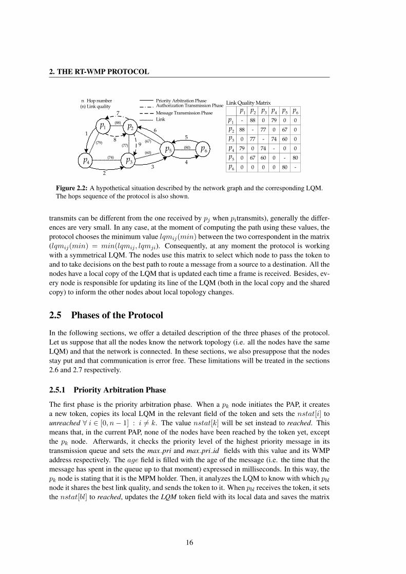
2. THE RT-WMP PROTOCOL
1
23
4
7
6
589
Priority Arbitration PhaseAuthorization Transmission Phase
Message Transmission Phase
3p4p
5p 6p
- 88 0 79 0
88 - 77 0 67
0 77 - 74 60
79 0 74 - 0
0 67 60 0 -
0 0 0 0 80
0
0
0
0
80
-
Link Quality Matrix
Link
(80)
(60)
(67)(77)
(74)
(79)
(88)
n(n) Link quality
Hop number
1p 2p
1p
1p
6p
5p
4p
3p
2p
2p
3p
4p
5p
6p
Figure 2.2: A hypothetical situation described by the network graph and the corresponding LQM.The hops sequence of the protocol is also shown.
transmits can be different from the one received by pj when pitransmits), generally the differ-ences are very small. In any case, at the moment of computing the path using these values, theprotocol chooses the minimum value lqmij(min) between the two correspondent in the matrix(lqmij(min) = min(lqmij , lqmji). Consequently, at any moment the protocol is workingwith a symmetrical LQM. The nodes use this matrix to select which node to pass the token toand to take decisions on the best path to route a message from a source to a destination. All thenodes have a local copy of the LQM that is updated each time a frame is received. Besides, ev-ery node is responsible for updating its line of the LQM (both in the local copy and the sharedcopy) to inform the other nodes about local topology changes.
2.5 Phases of the Protocol
In the following sections, we offer a detailed description of the three phases of the protocol.Let us suppose that all the nodes know the network topology (i.e. all the nodes have the sameLQM) and that the network is connected. In these sections, we also presuppose that the nodesstay put and that communication is error free. These limitations will be treated in the sections2.6 and 2.7 respectively.
2.5.1 Priority Arbitration Phase
The first phase is the priority arbitration phase. When a pk node initiates the PAP, it createsa new token, copies its local LQM in the relevant field of the token and sets the nstat[i] tounreached ∀ i ∈ [0, n− 1] : i 6= k. The value nstat[k] will be set instead to reached. Thismeans that, in the current PAP, none of the nodes have been reached by the token yet, exceptthe pk node. Afterwards, it checks the priority level of the highest priority message in itstransmission queue and sets the max pri and max pri id fields with this value and its WMPaddress respectively. The age field is filled with the age of the message (i.e. the time that themessage has spent in the queue up to that moment) expressed in milliseconds. In this way, thepk node is stating that it is the MPM holder. Then, it analyzes the LQM to know with which pblnode it shares the best link quality, and sends the token to it. When pbl receives the token, it setsthe nstat[bl] to reached, updates the LQM token field with its local data and saves the matrix
16
2.5 Phases of the Protocol
locally. It subsequently increases the value of the age field by a quantity equal to the durationof one token-pass hop, in order to update the age of the message that the token refers to. Thenit looks for the value of the max pri field of the token and compares it with the priority level ofthe highest priority message in its queue. If it verifies that it holds a higher priority message,it modifies the max pri and max pri id fields. If it holds a message with the same priority,however, it checks the age field of the token. If the message is older than the one carried by thetoken, it updates the token as well. Subsequently, it chooses the node with which it shares thebest link quality amongst the set of nodes not yet reached, and sends the token to it. If a nodeonly listens to its predecessor (i.e. the node that passed the token to it), it can return the tokento the predecessor after updating. This means that a node can receive the token several timesduring the same PAP. In that case it has the right to update the max pri and max pri id values.This behavior helps reduce the well-known priority inversion problem. The process is repeateduntil all the nodes have been reached by the token (i.e. nstat[i] = reached ∀ i). The last nodeto receive the token knows the MPM holder’s identity (which is contained in the max pri idfield) and is responsible for sending it the authorization. This node ends the PAP and initiatesthe ATP.
2.5.2 Authorization Transmission Phase
First of all, the node that starts the ATP calculates a path to reach the destination node. To dothis, it applies the well known Dijkstra algorithm [Dijkstra59] to a distance matrix derived fromthe LQM as described in section 2.6.3. The Dijkstra algorithm returns a path to the destinationas a set P = {pp1 ..ppm} of nodes. Then the node creates an authorization and fills the aut destand aut src fields with the MPM holder address and its own address respectively, and sends theauthorization to the first node of the path. When pp1 receives the authorization, it looks at theaut dest field and if it contains its address, it ends the ATP and initiates the MTP. Otherwise, itcalculates the P ′ = {p′p1 ..p
′p(m−1)
} path, where p′pk = pp(k+1) k<m. In other words, since thecalculation is executed over the same LQM, the path calculated will be the same, except thatthe first hop has already taken place. Since all the nodes have the same topological information,recalculation of the path in each hop allows the saving of the bandwidth needed to propagateit. The node repeats the process just explained, routing the message to the next member of thepath, leaving the aut dest field unchanged.
2.5.3 Message Transmission Phase
When the MPM holder receives the authorization to transmit, it takes the highest priority mes-sage out from its transmission queue, creates a new message frame and places the data in thedata field. It fills the msg src and msg dest fields with its address and with the destinationaddress and calculates the path to the destination, just like in the ATP. Then it fills the priorityand len fields with the message’s priority and data length and sends it to the first node thatbelongs to the path. When the latter receives the message, it checks the msg dest field. If itcontains its address (i.e. if it is the destination) it pushes the message into the receiption queueand starts a new PAP. Otherwise, it repeats the computation of the path and repeats the process
17
2. THE RT-WMP PROTOCOL
just explained, routing the message to the next member of the path and leaving the msg destfield unchanged.
An explicit acknowledgment is not included because it would create too much overhead.However, if the message reaches the destination node, the latter introduces its WMP address inthe lack field of the new token before initiating the new PAP. During this PAP, the token willreach the sender of the previous message, who can check if the message has been delivered ornot by looking at the lack field.
2.6 Mobility Management
Topology can change frequently in MANETS. If nodes are moving, the radio signal and there-fore link quality amongst them varies and these changes must be rapidly reflected in the globalstatus of the network. Consequently, when a node discovers a change, it has to propagate thisinformation as soon as possible. In RT-WMP this task is carried out by the token in the PAPphases. In fact, topological information travels with it in the LQM and is updated in each hop.
2.6.1 LQM Actualization
As explained earlier, each line LQMk of the LQM describes the links of the pk node with allthe nodes of the network. Nodes can easily obtain information to fill the relevant line of thematrix. In fact, when a node sends a frame of any type, its neighbors —due to the broadcastingnature of the wireless medium— listen to the transmission and read the radio signal from thenetwork layer to update its local LQM. These changes have to be reflected in the shared LQMas soon as possible, to allow the nodes to correctly calculate the paths in the ATP and MTP.Therefore, when a pk node receives a token, it updates the LQMk line of the LQM token field,saves the whole matrix locally to use it in the successive ATP and MTP, and then retransmits it.Since the LQM reaches all the nodes frequently, they have accurate and up-to-date informationon the network’s (link-quality) topology. Consequently, if two nodes are moving away fromeach other, link quality will gradually fall until it reaches a value close to zero, after which thelink is lost. This value is reflected in the LQM, and nodes, whenever possible, will avoid thatlink to route information when link quality is beneath a certain threshold. In any case, due tothe technique used to update the LQM, the value 0 never would appear, and the last positivevalue would be maintained until an error were verified (see section 2.7). To avoid this behavior,we introduced a timeout on the validity of the values of the local LQM elements called LQMElement Validity Period (LEVP). If the pk node has a local LQM where lqmkl > 0 but does nothear a transmission from node pl within a certain timeout, then pk supposes that pl is not nearit yet, and sets that value to 0. The frequency with which each node receives the token dependson the number of nodes, on the maximum message size and on network rate. However, in a11 Mbps 802.11 network with 10 nodes and messages 1500 bytes long, if a node is movingat 5 m/s (18 km/h), it may have moved about 7.5 cm between the reception of one token andthe next one (including a work-case ATP and an MTP). This guarantees that LQM reflects thetopology of the network well at all times. However, there is an additional method to maintainthe LQM up-to-date. When a node sends a token, all of its neighbors receive the frame. While
18
2.6 Mobility Management
the destination processes the frame and makes the appropriate decision, the other nodes updatetheir local information on link quality with the sender, as explained earlier. Moreover, if theframe received contains a more recent LQM they can use it to update their own.
2.6.2 LQM Misalignment
Even if nodes receive the complete LQM frequently, sometimes a slight misalignment of theLQM can occur. This fact may lead to an undesired behavior of the protocol that can provokeinfinite loops in the ATP and MTP phases.
Let us consider the case in which pk, pa, pb can hear each other and that pk has to senda message to a fourth node pc that only pa and pb can hear. When pk computes the path, itconsiders the best is, for example, pa, pk, pc. However, when the message reaches pa, the latterconsiders, due to a small misalignment of the LQMs among nodes, that the safer path is pb, pcand instead of passing the message directly to pc, passes it back to pb. In the same way, pb canconsider, instead, that the safer path is just pa, pk. In this situation the pa and pb nodes wouldpass the message to each other indefinitely.
To avoid this situation, during both authorization and message delivery, when a node re-ceives a frame, it sets its corresponding bit in the nyr field before propagating it. The receivingnode applies the mask constituted by the string of bits to the LQM setting lqmij = 0 andlqmji = 0 being i the local node and j the node corresponding to the set bit.
With the additional step just described, when pb receives the message for the first time, itdiscards the possibility of sending the message back to pa avoiding, in fact, the possibility ofinfinite loops and guaranteeing the upper bound of n− 1 hops even in the event of misalignedLQMs.
2.6.3 Specific LQM Elements Values
As mentioned earlier, the lqmij elements of the LQM are functions of the radio signal linksbetween nodes. To calculate them, we use the Received Signal Strength Indicator (RSSI)defined by the 802.11 protocol. The physical sublayer measures the energy observed at theantenna used to receive the current frame. Normally, 802.11 devices provide this value to thedevice driver. Besides, some card models provide information on noise as well. With thesetwo parameters, we can estimate the Signal to Noise Ratio (SNR) for every frame received andestimate link quality between nodes, representing it with values in the [0,max lq] range. Thecalculation of the path in the ATP and MTP is based on these values. The Dijkstra algorithmfor the single-source shortest path problem for directed graphs with nonnegative edge weightsis applied to the graph that represents the matrix M , derived by means of a simple heuristicfrom the LQM. However, the heuristic is not linear, as longer paths are preferred to shorterones containing very bad links. Computation time is not an issue (networks are usually small),since the Dijkstra algorithm has a O(V 2) complexity, V being the number of vertices, whereasthe implementation of the algorithm’s priority queue with a Fibonacci heap makes the timecomplexity O(E + V logV ), where E is the number of edges of the considered graph.
19
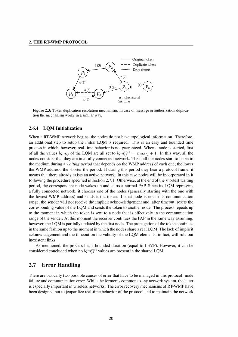
2. THE RT-WMP PROTOCOL
1 (1)
2 (2)
3 (3)
3 (4)
4 (4)
4 (5)
4 (6)
Original token
Duplicate token
Drop frame
n : token serial(n): time
3p
1p
4p
2p
5p 6p
Figure 2.3: Token duplication resolution mechanism. In case of message or authorization duplica-tion the mechanism works in a similar way.
2.6.4 LQM Initialization
When a RT-WMP network begins, the nodes do not have topological information. Therefore,an additional step to setup the initial LQM is required. This is an easy and bounded timeprocess in which, however, real-time behavior is not guaranteed. When a node is started, firstof all the values lqmij of the LQM are all set to lqminit
ij = maxlq + 1. In this way, all thenodes consider that they are in a fully connected network. Then, all the nodes start to listen tothe medium during a waiting period that depends on the WMP address of each one; the lowerthe WMP address, the shorter the period. If during this period they hear a protocol frame, itmeans that there already exists an active network. In this case nodes will be incorporated in itfollowing the procedure specified in section 2.7.1. Otherwise, at the end of the shortest waitingperiod, the correspondent node wakes up and starts a normal PAP. Since its LQM representsa fully connected network, it chooses one of the nodes (generally starting with the one withthe lowest WMP address) and sends it the token. If that node is not in its communicationrange, the sender will not receive the implicit acknowledgement and, after timeout, resets thecorresponding value of the LQM and sends the token to another node. The process repeats upto the moment in which the token is sent to a node that is effectively in the communicationrange of the sender. At this moment the receiver continues the PAP in the same way assuming,however, the LQM is partially updated by the first node. The propagation of the token continuesin the same fashion up to the moment in which the nodes share a real LQM. The lack of implicitacknowledgement and the timeout on the validity of the LQM elements, in fact, will rule outinexistent links.
As mentioned, the process has a bounded duration (equal to LEVP). However, it can beconsidered concluded when no lqminit
ij values are present in the shared LQM.
2.7 Error Handling
There are basically two possible causes of error that have to be managed in this protocol: nodefailure and communication error. While the former is common to any network system, the latteris especially important in wireless networks. The error recovery mechanisms of RT-WMP havebeen designed not to jeopardize real-time behavior of the protocol and to maintain the network
20
2.7 Error Handling
temporization in the majority of possible situations of error.
2.7.1 Node Failure or Node Loss
RT-WMP is quite robust in case of node failure. The implicit acknowledge technique useddispenses with the necessity of monitoring nodes to control the loss of the token. In fact, incommon token-pass systems with explicit acknowledgement, when a node receives a token, itacknowledges the sender with a message. However, if a node fails just after the acknowledge-ment, the token is lost and a technique to regenerate it is required. In RT-WMP, however, whena pk node sends a frame of any type, it listens to the channel for a timeout. The receiver pl nodeimmediately processes the frame received and sends another frame to a third pm node (that canbe its predecessor as well). The first sender listens to such a frame as well and interprets itas an acknowledgement. This technique permits saving of bandwidth and eliminates the needfor a monitor node. In any case, if the first sender does not hear the frame within timeout, itsupposes that the pl node has failed or is out of its coverage range. In this case, the behaviordepends on the phase that the protocol is in. If it is in the ATP or MTP, pk discards the frameand starts a new PAP. In fact, it is impossible to calculate another path since this could jeopar-dize the temporization of the network (see section 2.8.1). However, if it is in the PAP, pk nodesets the nstat[l] field to reached, modifies the local LQM and the LQM carried by the tokento exclude the pl node from the set of its neighbors (setting lqmkl = 0) and continues with thePAP, sending the token to another node. This solution excludes the pl node in the current PAPto preserve network temporization but not necessarily in the next PAP. In fact, it may be thatthere are other nodes which consider pl to be their neighbor. If pl has not actually failed but,for instance, has moved away from pk node but not from another neighbor pm, the latter willreinsert pl in the next PAP by simply passing it the token with no additional cost. If, however,the node is actually broken or has moved away from all the other nodes, in the next PAPs allits neighbors will try to pass the token to it one after another (one in each PAP) until pl isisolated. When this occurs, the node that starts the next PAP marks this node as lost settingnstat(l) = lost + r where r is a number between 0 and n − 1 and pr does not belong to theset of lost nodes.
Reinsertion of lost nodes.
The number r represents the identity of the node that has to search for the lost node in thecurrent PAP. Nodes, in fact, could reappear, but it is impossible to predict where. Consequently,nodes that still belong to the network organize themselves to search for the lost node one afteranother in the successive PAPs. When pr node receives the token, it looks at the nstat array. Ifone of the elements contains the value lost+r, (in this case nstat[l] = lost+r), it tries to sendthe token to pl. If the latter (implicitly) acknowledges the frame (i.e. passes the token to anothernode or back to pr), it is reinserted in the network with no additional cost. Otherwise, (i.e. plnode does not acknowledge) node pr sets nstats(l) = searched + r and continues the PAP.None of the other nodes try to search for that node in the current PAP, since this would breakthe network temporization (see 2.8.1 for details). The node that starts the next PAP modifiesthe field nstats to nstats[l] = lost+ ((r + 1)mod n) if p(r+1) mod n node is not a lost node
21

2. THE RT-WMP PROTOCOL
3
6 5
47
1 2
p5
p3
p2
p4
p1
Figure 2.4: Worst case PAP situation.
and continues the PAP. In this manner all the nodes not lost will search for the lost node oneafter another in the successive PAPs until reinsertion of the node takes place. This mechanismworks with more than one lost node in the same way.
2.7.2 Frame Duplication
Communication errors can produce another type of problem. Let us consider the situationwhere, in the PAP, the pk node sends a token to the pa node and waits for an implicit acknowl-edgment. Node pa processes the frame and sends the frame to node pb. As explained earlier,the last pass is also the acknowledgement for pk. However, if node pb hears the frame but pkdoes not, a token duplication occurs. In fact, pk marks the node as reached (like in the case ofa failed token-pass explained earlier) and continues the PAP by sending the token to anothernode. Node pb continues the PAP as well and at that moment there are two tokens in the net-work. To solve this problem we introduced the serial field in the frames. This field containsa value that is set to zero when the first PAP begins. Before each transmission, the sendernode increases this value, saves it locally, and then transmits. However, when a node receivesa frame with a serial lower to or equal than the highest serial that it has transmitted, it discardsthe frame and informs the sender by sending a drop frame to it. In figure 2.3 an example situa-tion is presented. authorization or message duplication can occur in the same way. In keepingwith the behavior described earlier, the unacknowledged node discards the message or the au-thorization and creates a new token frame. However, the receiver of the authorization/messagecontinues to route the frame along the path. At that moment there are two distinct types offrame traveling in the network. Just as in the case of a simple token duplication, though, thefirst node that receives a frame with an old serial (either token or authorization/message) willdiscard it.
2.7.3 Frame Retransmission
To have the possibility of guaranteeing a higher error endurance, in the current version of theRT-WMP protocol, a possibility of frame retransmission has been implemented. When a nodesends a frame but does not receive an implicit acknowledgment within timeout, it can reattemptthe transmission a fixed number of times. However, the use of this capability can provoke,
22

2.8 Real-Time Features
2n-3 hops n-1 hops n-1 hops 2n-3 hops
tokent
t= (2n-3) pat t (wc) =(n-1) aatt (wc) t =(n-1) mmtt (wc) t
(wc)
Figure 2.5: Timing of the protocol.
in some situations, similar problems to frame duplication. Let us consider the situation inwhich pk node sends a frame to the pa and the latter to pb. If pk node does not hear theacknowledgement , it will reattempt the transmission to pa that will receive a duplicated framethat should not propagate. In this case pa recognizes that it is the same frame looking at theserial and retry fields and send a drop frame back to the pk node that is informed, in this way,that it must discard the frame. On the other hand, this capability alters the real-time timingof the protocols (see section 2.8.2) and must be considered at the planning time since eachtransmission can entail n retransmissions.
2.8 Real-Time Features
In a real-time distributed system, priority support and bounded end-to-end delay is requiredfor scheduling and time constraint guarantees. Consequently, each event/phase in a real-timenetwork protocol must have a bounded and known duration.
2.8.1 Phases Boundness
The RT-WMP fulfils these requirements, since each phase has a bounded and known duration,even in the presence of the majority of errors. The PAP lasts, in the worst-case, 2n − 3 hops(see fig. 2.4). In fact, if the network is connected, a covering tree with n − 1 arcs can alwaysbe found, so the tree can be covered by visiting all its nodes two times at the most. That wouldmean 2n−2 hops, but a return to the first node can be avoided; therefore, there are only 2n−3hops. Besides, in error situations, such as node failure or node reinsertion (or loss), this phasehas the same duration, since the time wasted on a failed token pass can be equated to the timeneeded to send and return a token. Let us consider an example. Suppose that pk is the onlyneighbor of pa. In the normal functioning of the protocol, if node pk sends the token to pa,the latter shall pass the token back to pk to continue the PAP. However, if node pa is broken,after the pass node pk will wait for a timeout and then continue with the PAP passing the tokenon to another node. In fact, the time spent in the first and second scenario is the same, sincethe timeout is equal to the time that node pa needs to return the token. Frame duplication isthe only situation that can temporarily jeopardize real-time behavior of the network due to thepossibility of collisions and the need to send drop frames. In any event, the duration of thissituation is limited since the first node to receive an old frame discards it and informs the senderthat its frame is old.
In the ATP and MTP, the path is determined using the well-known Dijkstra algorithm (seesection 2.6.3 for details). According to this algorithm, if the network is connected, the max-
23

2. THE RT-WMP PROTOCOL
Table 2.1: Timing of the protocol for 11 Mbps data rate and message 512 bytes long. Times areexpressed in ms.
Nodes 3 4 5 10 20tt 0.282 0.287 0.295 0.353 0.578ta 0.271 0.271 0.271 0.271 0.271tm 0.646 0.646 0.646 0.646 0.646tpa(wc) 0.846 1.43 2.06 6.02 21.4tat(wc) 0.542 0.813 1.08 2.43 5.15tmt(wc) 1.29 1.93 2.58 5.81 12.28ttoken(wc) 3.52 5.63 7.80 20.2 60.2tete(wc) 5.36 8.38 11.4 28.5 77.6
imum number of hops to go from one node to another is n − 1. Thus these phases have abounded duration as well. However, in case of node failure or loss during these phases, nodesshall discard the authorization or the message in order not to jeopardize the temporization ofthe network. For example, let us suppose that pk node calculates a n − 1 hops path to reachdestination node pd. If one hop along the path fails, for instance pa to pb, pa node might findanother path to reach pd. Unfortunately, it may also occur that the sum between the numberof hops already made and the number of hops of the new path is greater than the allowedmaximum, that is n− 1.
2.8.2 Timing and Bandwidth
From the global point of view, the phases of the protocol repeat one after another, as we cansee in figure 2.5 with worst-case durations tpa(wc) = (2n− 3)tt for the PA phase, tat(wc) =(n− 1)ta for the ATP and tmt(wc) = (n− 1)tm for the MTP, tt being the duration of a tokenpass, ta the duration of an authorization pass and tm the duration of a message pass. Theworst-case loop can thus be defined as:
tloop(wc) = tpa(wc) + tat(wc) + tmt(wc) (2.1)
The absolute values of tt, ta and tm depend on protocol parameters such as the number ofnodes, the data rate and the maximum transmission unit (MTU) that the network has to carry,the number of retransmissions considered at the RT-WMP layer as well as the delay introducedby the underlying 802.11 protocol.
Retransmissions
When a node sends a frame (duration tframe), it waits during a timeout (tframe) for the re-ception of the implicit acknowledgement. If it does not receive it, it reattempts the emission(again, duration tframe). Each retransmission thus triples the duration of a frame transmission.
24
2.8 Real-Time Features
In this case:t′t = 3 · nr · tt, t′a = 3 · nr · ta, t′m = 3 · nr · tm (2.2)
being nr the fixed number of retries, t′t, t′a and t′m the time needed to send a token, an autho-
rization and a message in the presence of retransmissions respectively.
802.11
Before transmitting, a node always has to wait for a time interval called the DCF InterframeSpace (DIFS). The DIFS has a fixed duration of 50µs, which has to be taken into account whenvalues tt, ta and tm are calculated. Regardless of network speed, however, there is a part ofthe 802.11 frame that is always sent at 1 Mbps (the PLPC preamble and header) and has afixed duration of 192µs when a long preamble is used and 96µs if, instead, a short preamble ispreferred. Finally, we have the MAC header and the FCS, which together add 28 bytes and aretransmitted at the actual effective bitrate.
2.8.3 Timing
Taking into account the parameters just presented, the transmission duration of frames can becalculated as:
tframe(µs) = (192 + 50) +(28 + L) · 8tx rate(bps)
(2.3)
L being the payload of the 802.11 frame, including the protocol overhead. With these data wecan calculate that an upper bound on the interval between two consecutive receptions of a tokencan be expressed as:
ttoken(wc) = 2tpa(wc) + tat(wc) + tmt(wc) = tloop(wc) + tpa(wc) (2.4)
Intuitively, this occurs if a node starts a worst-case PAP (in which it does not receive the tokenback) and has to wait for the completion of the subsequent worst-case ATP and MTP, andreceives again the token after the last hop of an additional worst-case PAP.
On the other hand, the highest priority message in the network (if it is the only one) couldsuffer a worst-case delay of:
tete(wc) = ttoken(wc)+tat(wc)+tmt(wc) = 2·(tpa(wc)+tat(wc)+tmt(wc)) = 2·tloop(wc)(2.5)
Again, this can occur when the node that holds the most priority message is the PAP beginnerof the situation described and the message enters the queue just after its token pass. In thatcase it can occur that the message has to wait for a complete ttoken(wc) period plus additionalworst-case ATP and MTP. This expression represents the maximum priority-inversion delayalso, since lower-priority messages can not be preempted during an already started loop. Table2.1 illustrates a few results for different values of the “number of the nodes” parameter for a 11Mbps network rate and a MTU of 512 bytes.
25

2. THE RT-WMP PROTOCOL
2 3 4 5 6 7 8 9 10 11 120
1
2
3
4
5
6
7
Nodes
Th
rou
gh
pu
t (M
bp
s)
802.11
802.11 RTS/CTS
RT−WMP
Figure 2.6: Comparison between RT-WMP and 802.11 for the worst-case situation.
2.8.4 Bandwidth
With the temporization just expounded we can easily calculate the worst-case theoretical (end-to-end) bandwidth offered by the protocol as follows:
BW (Mbps) =MTU · 8
tpa(wc)(µs) + tat(wc)(µs) + tmt(wc)(µs)(2.6)
Our goal was to compare this with the 802.11 protocol to offer a rough idea of the overheadimposed by RT-WMP. However, before analyzing a comparison of results, it may be helpful toraise a few issues concerning 802.11 throughput. According to [Jun03], the theoretical (in theabsence of errors) effective available bandwidth offered by the 802.11b protocol (at 11 Mbps) isabout 6.1 Mbps for packets 1500 bytes long. If the RTS/CTS mechanism is used to alleviate thehidden terminal problem, this value drops to about 4.5 Mbps. On the other hand, 802.11 doesnot support multi-hop routing and this feature has to be implemented by means of upper layerrouting protocols such as AODV, DSVD, etc. However, regardless of the overhead introducedby the routing protocol used, end-to-end bandwidth is highly dependent on network topologyand the number of nodes in the network. In fact, according to [Sobrinho99], a transmissioncan cause interference in a range larger than the range of communication (almost two times thelatter). Nodes within the carrier sensing range of a transmitting node can sense the carrier ofthe sender even if they cannot hear the frame, and thus delay its transmission. According toour research, in relatively small wireless networks (up to 10-12 nodes) there can be situations
26
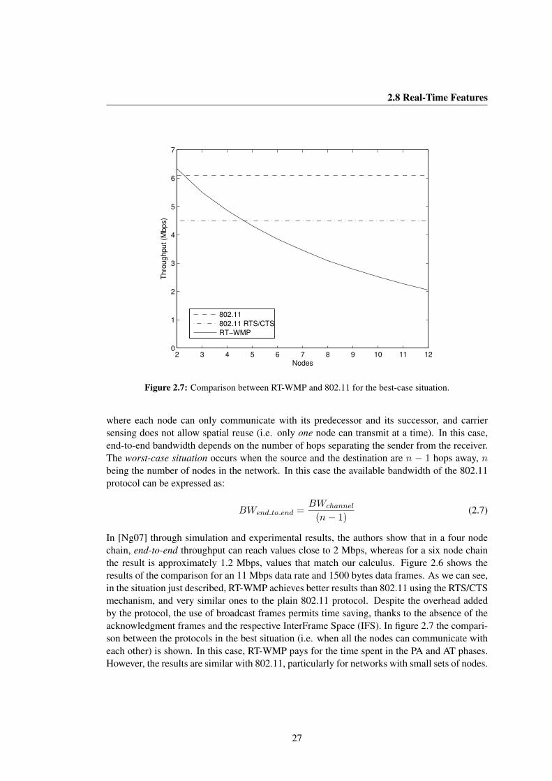
2.8 Real-Time Features
2 3 4 5 6 7 8 9 10 11 120
1
2
3
4
5
6
7
Nodes
Th
rou
gh
pu
t (M
bp
s)
802.11
802.11 RTS/CTS
RT−WMP
Figure 2.7: Comparison between RT-WMP and 802.11 for the best-case situation.
where each node can only communicate with its predecessor and its successor, and carriersensing does not allow spatial reuse (i.e. only one node can transmit at a time). In this case,end-to-end bandwidth depends on the number of hops separating the sender from the receiver.The worst-case situation occurs when the source and the destination are n − 1 hops away, nbeing the number of nodes in the network. In this case the available bandwidth of the 802.11protocol can be expressed as:
BWend to end =BWchannel
(n− 1)(2.7)
In [Ng07] through simulation and experimental results, the authors show that in a four nodechain, end-to-end throughput can reach values close to 2 Mbps, whereas for a six node chainthe result is approximately 1.2 Mbps, values that match our calculus. Figure 2.6 shows theresults of the comparison for an 11 Mbps data rate and 1500 bytes data frames. As we can see,in the situation just described, RT-WMP achieves better results than 802.11 using the RTS/CTSmechanism, and very similar ones to the plain 802.11 protocol. Despite the overhead addedby the protocol, the use of broadcast frames permits time saving, thanks to the absence of theacknowledgment frames and the respective InterFrame Space (IFS). In figure 2.7 the compari-son between the protocols in the best situation (i.e. when all the nodes can communicate witheach other) is shown. In this case, RT-WMP pays for the time spent in the PA and AT phases.However, the results are similar with 802.11, particularly for networks with small sets of nodes.
27
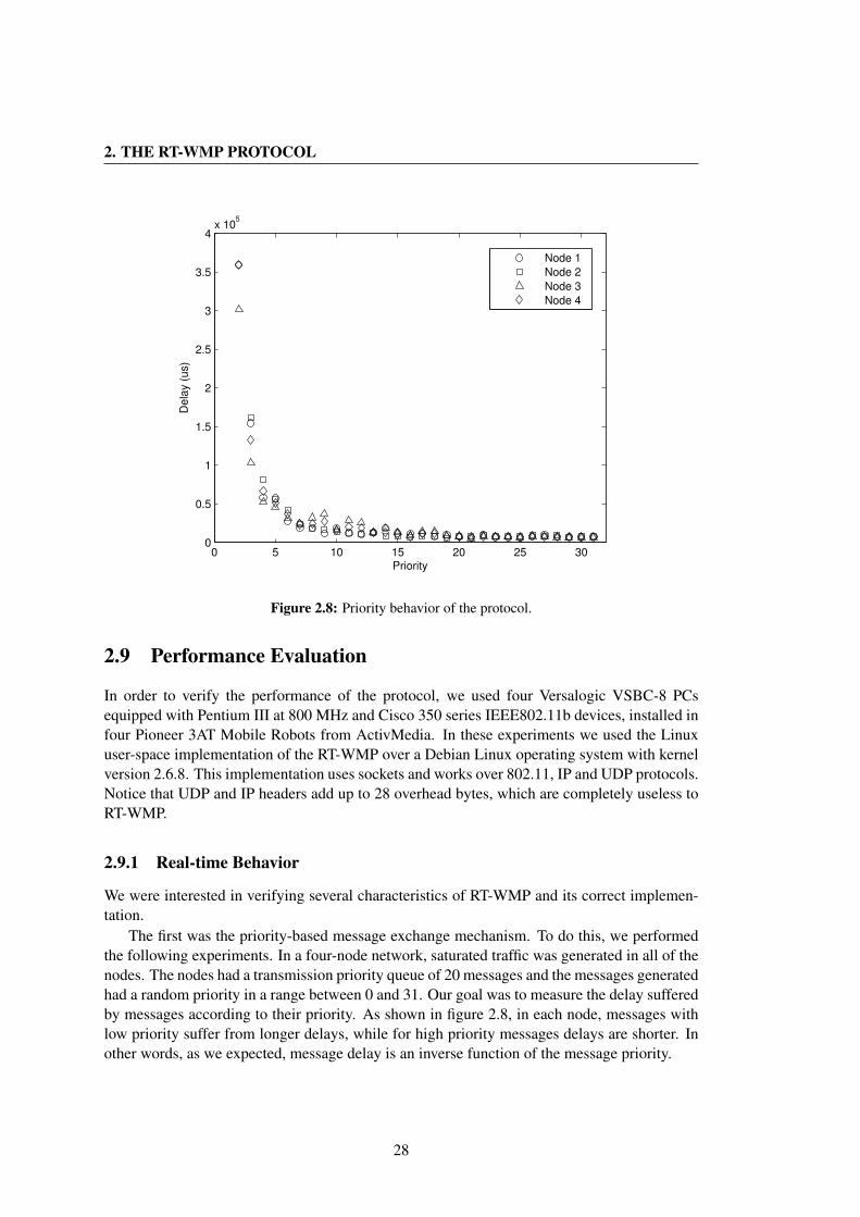
2. THE RT-WMP PROTOCOL
0 5 10 15 20 25 300
0.5
1
1.5
2
2.5
3
3.5
4x 10
5
Priority
De
lay (
us)
Node 1
Node 2
Node 3
Node 4
Figure 2.8: Priority behavior of the protocol.
2.9 Performance Evaluation
In order to verify the performance of the protocol, we used four Versalogic VSBC-8 PCsequipped with Pentium III at 800 MHz and Cisco 350 series IEEE802.11b devices, installed infour Pioneer 3AT Mobile Robots from ActivMedia. In these experiments we used the Linuxuser-space implementation of the RT-WMP over a Debian Linux operating system with kernelversion 2.6.8. This implementation uses sockets and works over 802.11, IP and UDP protocols.Notice that UDP and IP headers add up to 28 overhead bytes, which are completely useless toRT-WMP.
2.9.1 Real-time Behavior
We were interested in verifying several characteristics of RT-WMP and its correct implemen-tation.
The first was the priority-based message exchange mechanism. To do this, we performedthe following experiments. In a four-node network, saturated traffic was generated in all of thenodes. The nodes had a transmission priority queue of 20 messages and the messages generatedhad a random priority in a range between 0 and 31. Our goal was to measure the delay sufferedby messages according to their priority. As shown in figure 2.8, in each node, messages withlow priority suffer from longer delays, while for high priority messages delays are shorter. Inother words, as we expected, message delay is an inverse function of the message priority.
28
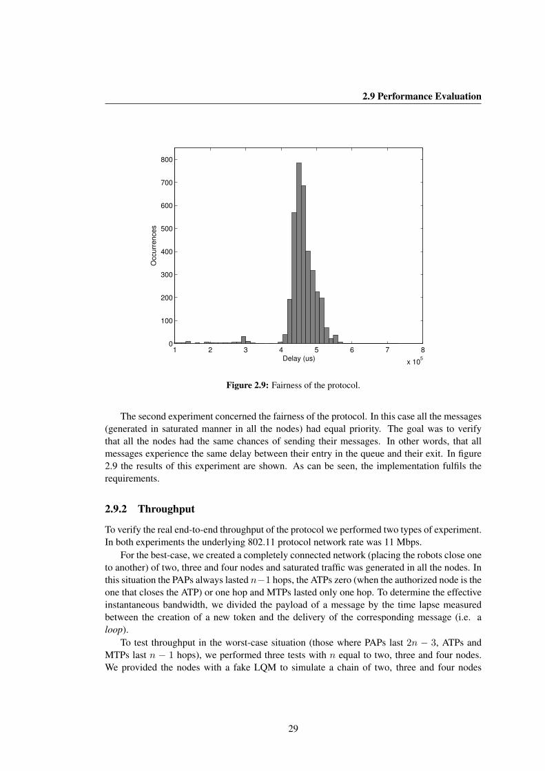
2.9 Performance Evaluation
1 2 3 4 5 6 7 8
x 105
0
100
200
300
400
500
600
700
800
Delay (us)
Occu
rre
nce
s
Figure 2.9: Fairness of the protocol.
The second experiment concerned the fairness of the protocol. In this case all the messages(generated in saturated manner in all the nodes) had equal priority. The goal was to verifythat all the nodes had the same chances of sending their messages. In other words, that allmessages experience the same delay between their entry in the queue and their exit. In figure2.9 the results of this experiment are shown. As can be seen, the implementation fulfils therequirements.
2.9.2 Throughput
To verify the real end-to-end throughput of the protocol we performed two types of experiment.In both experiments the underlying 802.11 protocol network rate was 11 Mbps.
For the best-case, we created a completely connected network (placing the robots close oneto another) of two, three and four nodes and saturated traffic was generated in all the nodes. Inthis situation the PAPs always lasted n−1 hops, the ATPs zero (when the authorized node is theone that closes the ATP) or one hop and MTPs lasted only one hop. To determine the effectiveinstantaneous bandwidth, we divided the payload of a message by the time lapse measuredbetween the creation of a new token and the delivery of the corresponding message (i.e. aloop).
To test throughput in the worst-case situation (those where PAPs last 2n − 3, ATPs andMTPs last n − 1 hops), we performed three tests with n equal to two, three and four nodes.We provided the nodes with a fake LQM to simulate a chain of two, three and four nodes
29
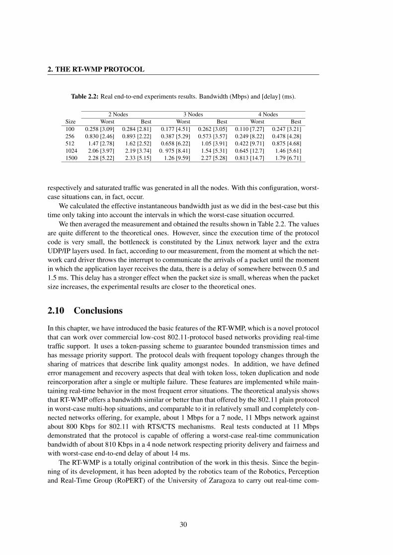
2. THE RT-WMP PROTOCOL
Table 2.2: Real end-to-end experiments results. Bandwidth (Mbps) and [delay] (ms).
2 Nodes 3 Nodes 4 NodesSize Worst Best Worst Best Worst Best100 0.258 [3.09] 0.284 [2.81] 0.177 [4.51] 0.262 [3.05] 0.110 [7.27] 0.247 [3.21]256 0.830 [2.46] 0.893 [2.22] 0.387 [5.29] 0.573 [3.57] 0.249 [8.22] 0.478 [4.28]512 1.47 [2.78] 1.62 [2.52] 0.658 [6.22] 1.05 [3.91] 0.422 [9.71] 0.875 [4.68]1024 2.06 [3.97] 2.19 [3.74] 0. 975 [8.41] 1.54 [5.31] 0.645 [12.7] 1.46 [5.61]1500 2.28 [5.22] 2.33 [5.15] 1.26 [9.59] 2.27 [5.28] 0.813 [14.7] 1.79 [6.71]
respectively and saturated traffic was generated in all the nodes. With this configuration, worst-case situations can, in fact, occur.
We calculated the effective instantaneous bandwidth just as we did in the best-case but thistime only taking into account the intervals in which the worst-case situation occurred.
We then averaged the measurement and obtained the results shown in Table 2.2. The valuesare quite different to the theoretical ones. However, since the execution time of the protocolcode is very small, the bottleneck is constituted by the Linux network layer and the extraUDP/IP layers used. In fact, according to our measurement, from the moment at which the net-work card driver throws the interrupt to communicate the arrivals of a packet until the momentin which the application layer receives the data, there is a delay of somewhere between 0.5 and1.5 ms. This delay has a stronger effect when the packet size is small, whereas when the packetsize increases, the experimental results are closer to the theoretical ones.
2.10 Conclusions
In this chapter, we have introduced the basic features of the RT-WMP, which is a novel protocolthat can work over commercial low-cost 802.11-protocol based networks providing real-timetraffic support. It uses a token-passing scheme to guarantee bounded transmission times andhas message priority support. The protocol deals with frequent topology changes through thesharing of matrices that describe link quality amongst nodes. In addition, we have definederror management and recovery aspects that deal with token loss, token duplication and nodereincorporation after a single or multiple failure. These features are implemented while main-taining real-time behavior in the most frequent error situations. The theoretical analysis showsthat RT-WMP offers a bandwidth similar or better than that offered by the 802.11 plain protocolin worst-case multi-hop situations, and comparable to it in relatively small and completely con-nected networks offering, for example, about 1 Mbps for a 7 node, 11 Mbps network againstabout 800 Kbps for 802.11 with RTS/CTS mechanisms. Real tests conducted at 11 Mbpsdemonstrated that the protocol is capable of offering a worst-case real-time communicationbandwidth of about 810 Kbps in a 4 node network respecting priority delivery and fairness andwith worst-case end-to-end delay of about 14 ms.
The RT-WMP is a totally original contribution of the work in this thesis. Since the begin-ning of its development, it has been adopted by the robotics team of the Robotics, Perceptionand Real-Time Group (RoPERT) of the University of Zaragoza to carry out real-time com-
30

2.10 Conclusions
munications and has been used in many real indoor and outdoor experiments detailed in theappendix B. At the moment the protocol can run over the Linux and MaRTE OS operatingsystem using standard commercial hardware.
31

2. THE RT-WMP PROTOCOL
32
Chapter 3
Multicast Extension
Normally, point-to-point communication is sufficient to allow collaboration in cooperativerobot team missions. However, there are situations in which multicast and/or broadcast ca-pabilities, even with real-time requirements, allow a better usage of the available bandwidthleaving more time for possible unicast communications. This is the case, for example, when aserver generates real-time traffic that has to be delivered to a subset (that can be the whole set)of the nodes of the network.
Real-time multicast refers to a multicast in which a message will be received by more thanone destination within a specified time delay [Jia96]. Sharing information among n robotsusing unicast messages would imply sending n2 messages each time and would lead, in mostcases, to the whole available bandwidth being occupied with the consequent impossibility ofsending any other flow of information. The use of a multicast protocol, however, allows thesharing of information among the members of a network without wasting bandwidth.
In this chapter we present an extension to RT-WMP partially motivated by the need for anefficient form of exchange consistent huge amount of laser data in a robot team [Urcola09]. Theprotocol allows multicast and broadcast communications while taking advantage of the framesexchanged during normal operations. Even in this case messages are delivered following apriority order and can be preempted during their path to their destination. In addition, usingthese new characteristics, another type of unicast/multicast protocol is proposed, analyzed,evaluated and compared with the plain RT-WMP.
This extension to the basic protocol has been developed within the framework of the NEROSpanish National Project and the Ubiquitous Networking Robotics in Urban Settings - URUS(IST-1-045062-URUS-STP) project of the European Commission. It was presented at the 14thIEEE International Conference on Emerging Technologies and Factory Automation held inPalma de Mallorca (Spain) from 22 to 26 September 2009 with the contribution “AddingMulticast Capabilities to Real-Time Wireless Multi-hop Protocols : Extending the RT-WMP”[Tardioli09].
33
3. MULTICAST EXTENSION
3.1 Related Work
The problem of supporting real-time wireless communication has received certain attentionin recent years and several works have been carried out, as described in the previous chapter.However, to the best of our knowledge, none of them propose solutions to real-time multi-cast communication but rather to some degree of QoS guarantee in order to give support tomultimedia multicast traffic. The recent development of broadband wireless technologies hasled researchers to contemplate the problem of multimedia traffic dissemination from differentpoints of view. In the solution proposed in [Majumda02], Majumdar et al. address the prob-lem of resilient real-time video streaming over IEEE 802.11b WLANs for both unicast andmulticast transmission. For the unicast scenario, a hybrid automatic repeat request (ARQ) al-gorithm that efficiently combines forward error correction (FEC) and ARQ is proposed. Forthe multicast case, progressive video coding based on MPEG-4 FGS is combined with FEC.This scheme, however, does not consider multi-hop delivery and efforts are concentrated onthe last-hop communication.
The Multi-Flow Real-Time Transport Protocol (MRTP) [Mao06] overcomes this limita-tion and offers multipath routing for multicast application in mesh networks. It is based onReal-Time Protocol (RTP) and Real-Time Transport Control Protocol (RTCP) [Schulzrinne96].MRTP is motivated by the observations of effective path diversity in combating transmissionerrors in ad-hoc networks, and effective data partitioning techniques in improving the queuingperformance of multimedia traffic.
The Multi-Objective Multipath Routing Algorithm for Multicast Flows (called MMRAM)[Fabregat04] proposes a multi-objective traffic-engineering scheme using different distributiontrees to multicast several flows. MMRAM tries to combine maximum link utilization, hopcount, total bandwidth consumption, and total end-to-end delay into a single aggregated flow.This multi-tree routing protocol uses a multicast transmission with load balancing.
In [Baccichet02] the authors propose the QoSM2P strategy. This allows any client tospecify their QoS requirements using as many constraints as necessary. This approach impliesthat every overlay node in the network is able to maintain information about QoS parameterson incoming paths and there is a mechanism in place to perform required measurements.
As is well known, however, QoS guarantees are less stringent than real-time ones. Real-time scheduling requires, in fact, bounded and known delays even for multicast delivery whileQoS can tolerate some jitter and packet loss.
3.2 The RT-WMP-PME Protocol
The use of unicast messages to connect a network is sufficient in many cases. However, thereare situations in which the use of point-to-point communication leads the system to waste band-width and in some cases to jeopardize the possibility of unicast communication. In RT-WMP,for example, if a message had to be sent to all of the nodes of the network, n messages wouldbe needed with the respective PAP, ATP and MTP. A worse case is one in which all the nodeshave to broadcast their messages to all of the other nodes. In this case n2 messages in anyiteration would be necessary. If the nodes needed to interchange information frequently, the
34
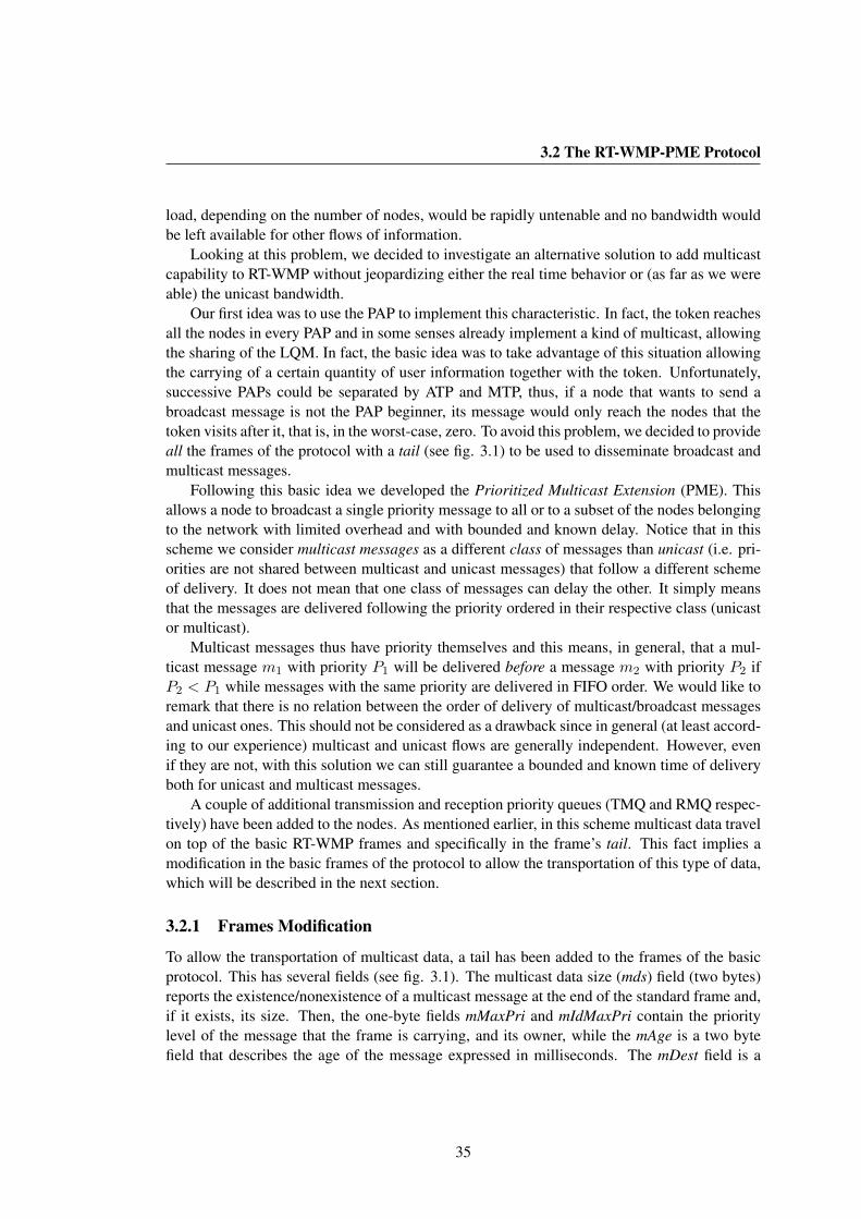
3.2 The RT-WMP-PME Protocol
load, depending on the number of nodes, would be rapidly untenable and no bandwidth wouldbe left available for other flows of information.
Looking at this problem, we decided to investigate an alternative solution to add multicastcapability to RT-WMP without jeopardizing either the real time behavior or (as far as we wereable) the unicast bandwidth.
Our first idea was to use the PAP to implement this characteristic. In fact, the token reachesall the nodes in every PAP and in some senses already implement a kind of multicast, allowingthe sharing of the LQM. In fact, the basic idea was to take advantage of this situation allowingthe carrying of a certain quantity of user information together with the token. Unfortunately,successive PAPs could be separated by ATP and MTP, thus, if a node that wants to send abroadcast message is not the PAP beginner, its message would only reach the nodes that thetoken visits after it, that is, in the worst-case, zero. To avoid this problem, we decided to provideall the frames of the protocol with a tail (see fig. 3.1) to be used to disseminate broadcast andmulticast messages.
Following this basic idea we developed the Prioritized Multicast Extension (PME). Thisallows a node to broadcast a single priority message to all or to a subset of the nodes belongingto the network with limited overhead and with bounded and known delay. Notice that in thisscheme we consider multicast messages as a different class of messages than unicast (i.e. pri-orities are not shared between multicast and unicast messages) that follow a different schemeof delivery. It does not mean that one class of messages can delay the other. It simply meansthat the messages are delivered following the priority ordered in their respective class (unicastor multicast).
Multicast messages thus have priority themselves and this means, in general, that a mul-ticast message m1 with priority P1 will be delivered before a message m2 with priority P2 ifP2 < P1 while messages with the same priority are delivered in FIFO order. We would like toremark that there is no relation between the order of delivery of multicast/broadcast messagesand unicast ones. This should not be considered as a drawback since in general (at least accord-ing to our experience) multicast and unicast flows are generally independent. However, evenif they are not, with this solution we can still guarantee a bounded and known time of deliveryboth for unicast and multicast messages.
A couple of additional transmission and reception priority queues (TMQ and RMQ respec-tively) have been added to the nodes. As mentioned earlier, in this scheme multicast data travelon top of the basic RT-WMP frames and specifically in the frame’s tail. This fact implies amodification in the basic frames of the protocol to allow the transportation of this type of data,which will be described in the next section.
3.2.1 Frames Modification
To allow the transportation of multicast data, a tail has been added to the frames of the basicprotocol. This has several fields (see fig. 3.1). The multicast data size (mds) field (two bytes)reports the existence/nonexistence of a multicast message at the end of the standard frame and,if it exists, its size. Then, the one-byte fields mMaxPri and mIdMaxPri contain the prioritylevel of the message that the frame is carrying, and its owner, while the mAge is a two bytefield that describes the age of the message expressed in milliseconds. The mDest field is a
35
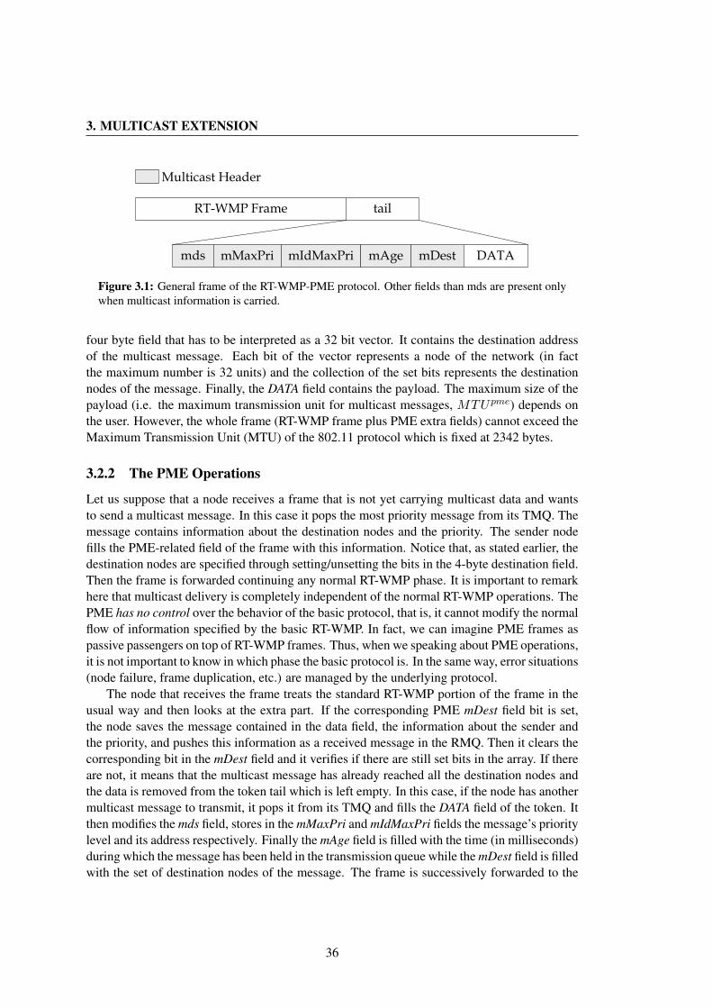
3. MULTICAST EXTENSION
mds mMaxPri
RT-WMP Frame tail
mIdMaxPri mAge mDest DATA
Multicast Header
Figure 3.1: General frame of the RT-WMP-PME protocol. Other fields than mds are present onlywhen multicast information is carried.
four byte field that has to be interpreted as a 32 bit vector. It contains the destination addressof the multicast message. Each bit of the vector represents a node of the network (in factthe maximum number is 32 units) and the collection of the set bits represents the destinationnodes of the message. Finally, the DATA field contains the payload. The maximum size of thepayload (i.e. the maximum transmission unit for multicast messages, MTUpme) depends onthe user. However, the whole frame (RT-WMP frame plus PME extra fields) cannot exceed theMaximum Transmission Unit (MTU) of the 802.11 protocol which is fixed at 2342 bytes.
3.2.2 The PME Operations
Let us suppose that a node receives a frame that is not yet carrying multicast data and wantsto send a multicast message. In this case it pops the most priority message from its TMQ. Themessage contains information about the destination nodes and the priority. The sender nodefills the PME-related field of the frame with this information. Notice that, as stated earlier, thedestination nodes are specified through setting/unsetting the bits in the 4-byte destination field.Then the frame is forwarded continuing any normal RT-WMP phase. It is important to remarkhere that multicast delivery is completely independent of the normal RT-WMP operations. ThePME has no control over the behavior of the basic protocol, that is, it cannot modify the normalflow of information specified by the basic RT-WMP. In fact, we can imagine PME frames aspassive passengers on top of RT-WMP frames. Thus, when we speaking about PME operations,it is not important to know in which phase the basic protocol is. In the same way, error situations(node failure, frame duplication, etc.) are managed by the underlying protocol.
The node that receives the frame treats the standard RT-WMP portion of the frame in theusual way and then looks at the extra part. If the corresponding PME mDest field bit is set,the node saves the message contained in the data field, the information about the sender andthe priority, and pushes this information as a received message in the RMQ. Then it clears thecorresponding bit in the mDest field and it verifies if there are still set bits in the array. If thereare not, it means that the multicast message has already reached all the destination nodes andthe data is removed from the token tail which is left empty. In this case, if the node has anothermulticast message to transmit, it pops it from its TMQ and fills the DATA field of the token. Itthen modifies the mds field, stores in the mMaxPri and mIdMaxPri fields the message’s prioritylevel and its address respectively. Finally the mAge field is filled with the time (in milliseconds)during which the message has been held in the transmission queue while the mDest field is filledwith the set of destination nodes of the message. The frame is successively forwarded to the
36

3.2 The RT-WMP-PME Protocol
next node following the basic RT-WMP behavior.If, however, not all the destination nodes have been reached yet, the receiver node compares
the priority level of the most priority message in its TMQ and the value carried by the mMaxPrifield of the frame. If the message carried by the frame has more priority than its own, the nodeonly updates the mAge field of the frame adding to that value the quantity corresponding tothe time spent in the last frame-pass, and it leaves RT-WMP to propagate the message in theusual way.
If, on the other hand, it figures out that it owns a more priority message, it pushes themessage contained in the PME part of the received frame (the multicast message) into its TMQand replaces it with its own. In this way the first message suffers temporarily from an expulsionfrom the network (preemption). However, by pushing it into the transmission queue of a node ofthe network, a belated delivery (according to its priority and age) of the message is guaranteed.In fact, the message will compete successively with the others already held in the transmissionqueue to be transmitted.
If a node holds a message with the same priority as the one just received, the mAge field iscompared and the oldest is selected to continue its dissemination.
The scheme just described guarantees the delivering of multicast messages to all the nodes(or to the specified subset) in a bounded time. This is easy to understand given that at least ineach PAP the token reaches all the nodes of the network.
Even if the scheme of delivery of RT-WMP does not change, the introduction of the PMEcauses a worsening in some of its characteristic values such as end-to-end delivery delay orbandwidth. However the effect, which depends on the maximum size of the multicast messageadmitted, is limited and known and can be easily calculated as explained in the next section.
3.2.3 Influence on RT-WMP Temporizations
According to equation 2.3, the transmission of any frame takes:
tframe(µs) = (192 + 50) +(28 + L) · 8tx rate(bps)
(3.1)
In the basic RT-WMP protocol, the value of L depends on the length of the frame consid-ered, as explained in the previous chapter. The introduction of the token tail alters these valuesand causes the value of L to grow for all the frames by a quantity equal to the multicast headerMH (10 bytes) plus the multicast payload (in the worst-case equal to maximum transmissionunit for multicast messages MTUpme). These changes cause an increment in the duration ofall of the phases of the protocol that, in turn, is reflected in the worst-case end-to-end deliverydelay. In order to quantify the influence of these modifications, it is useful to recover the con-cepts of loop as a succession of consecutive PAP, ATP and MTP and the loop duration tloop asthe time needed to complete a loop (i.e. the time needed to deliver a message starting from themoment in which a node begins a PAP). According to the syntax defined in chapter 2:
tloop = tpa + tat + tmt (3.2)
The worst-case loop tloop(wc) takes place when all the phases have the maximum duration,
37
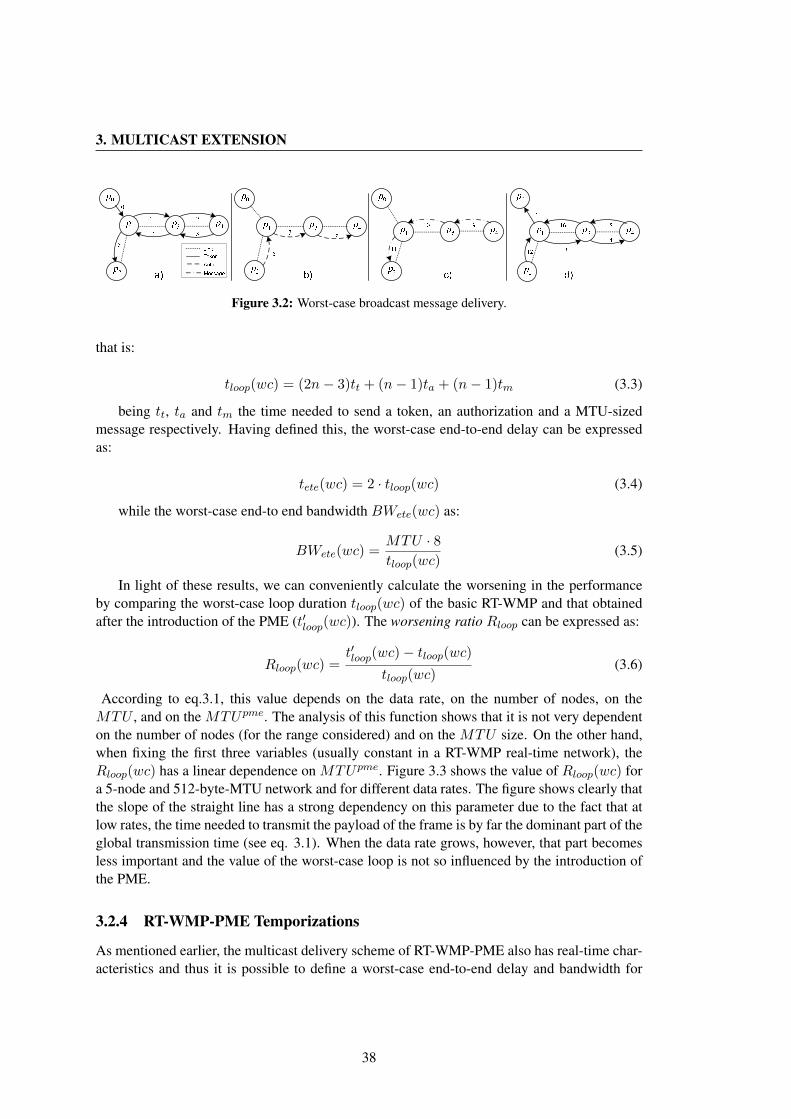
3. MULTICAST EXTENSION
Figure 3.2: Worst-case broadcast message delivery.
that is:
tloop(wc) = (2n− 3)tt + (n− 1)ta + (n− 1)tm (3.3)
being tt, ta and tm the time needed to send a token, an authorization and a MTU-sizedmessage respectively. Having defined this, the worst-case end-to-end delay can be expressedas:
tete(wc) = 2 · tloop(wc) (3.4)
while the worst-case end-to end bandwidth BWete(wc) as:
BWete(wc) =MTU · 8tloop(wc)
(3.5)
In light of these results, we can conveniently calculate the worsening in the performanceby comparing the worst-case loop duration tloop(wc) of the basic RT-WMP and that obtainedafter the introduction of the PME (t′loop(wc)). The worsening ratio Rloop can be expressed as:
Rloop(wc) =t′loop(wc)− tloop(wc)
tloop(wc)(3.6)
According to eq.3.1, this value depends on the data rate, on the number of nodes, on theMTU , and on the MTUpme. The analysis of this function shows that it is not very dependenton the number of nodes (for the range considered) and on the MTU size. On the other hand,when fixing the first three variables (usually constant in a RT-WMP real-time network), theRloop(wc) has a linear dependence on MTUpme. Figure 3.3 shows the value of Rloop(wc) fora 5-node and 512-byte-MTU network and for different data rates. The figure shows clearly thatthe slope of the straight line has a strong dependency on this parameter due to the fact that atlow rates, the time needed to transmit the payload of the frame is by far the dominant part of theglobal transmission time (see eq. 3.1). When the data rate grows, however, that part becomesless important and the value of the worst-case loop is not so influenced by the introduction ofthe PME.
3.2.4 RT-WMP-PME Temporizations
As mentioned earlier, the multicast delivery scheme of RT-WMP-PME also has real-time char-acteristics and thus it is possible to define a worst-case end-to-end delay and bandwidth for
38

3.2 The RT-WMP-PME Protocol
50 100 150 200 250 300 350 400 450 5120
0.2
0.4
0.6
0.8
1
1.2
1.4
Size (bytes)
Rlo
op(w
c)
1 Mbps5.5 Mbps11 Mbps
Figure 3.3: Behavior of Rloop(wc) for different data rates.
multicast messages as well. To this end, it is useful to introduce the multicast loop, a similarconcept to the loop defined for unicast messages. In this case its duration represents the timeneeded for a message to be delivered, in the absence of preemption, to all the destination nodesin the network, starting from the moment at which the message begins its travel. The durationof the multicast loop depends on the specific behavior of the underlying RT-WMP protocolsince multicast messages are delivered following the paths chosen by it. However, there is anupper bound on this value that can be written as:
tpmeloop(wc) = (4n− 9)tpmet + (n− 2)tpmea + (n− 2)tpmem (3.7)
being tpmet , tpmea and tpmem the values of tt, ta and tm for RT-WMP-PME. In fact, consid-ering figure 3.2, suppose that node p0 begins a normal PAP. When node p1 receives the framefrom node p0, the former begins the multicast message dissemination continuing the normalPAP and passing the token to node p3. The PAP continues as indicated in the figure and endswhen node p2 receives the token. At this moment the p1’s message has hopped 2n − 5 times(fig. 3.2.a). Node p2 starts the ATP (fig. 3.2.b) and it chooses the n − 2-hops path p1, p3 toreach the node p4 that is the destination of the authorization. Then node p4 chooses the samepath (but turned in reverse order) to send the message to p2 that is the destination of the mes-sage (fig. 3.2.c). Finally p2 begins another PAP that lasts, this time, 2n − 4 hops as shown infig. 3.2.d. The sum of the times results in the value expressed in equation 3.7.
Similarly to the case of unicast messages, the worst-case end-to-end bandwidth can beexpressed as:
BW pmeete (wc) =
MTUpme · 8tpmeloop(wc)
(3.8)
However, to the end of computing the end-to-end delay, we have to take into account that
39

3. MULTICAST EXTENSION
if this message does not enter the network at the exact moment in which p1 receives the framefor the first time (fig. 3.2.a), it has to wait some time in the protocol queue. This waiting canlast up to:
(4n− 9)tpmet + (n− 2)tpmea + (n− 2)tpmem = tpmeloop(wc) (3.9)
This is easy to understand if we assume that the message can be pushed into the p0 queuejust after the moment at which it sent the token to p1. In this case, in fact, it has to wait duringthe whole succession of events just described before receiving a frame again and being able tosend its message that, in turn, can take up to tpmeloop(wc) to be delivered to the whole set of nodesbelonging to the network.
Therefore, globally, we can express the worst-case end-to-end delay for multicast messagestpmeete (wc) as:
tpmeete (wc) = 2·tpmeloop(wc) =
2·((4n− 9)tpmet + (n− 2)tpmea + (n− 2)tpmem )
These values are valid in the case of both multicast and broadcast messages. This can easilybe explained given that node p0 could be contained (or could be the only node) in the set ofdestination nodes of the message sent by p1.
3.2.5 Unicast use of the PME
The PME has been considered to disseminate multicast messages to a subset or to the wholeset of nodes of the network. However, a subset can in fact consist of a single node. In this casethe communication converts into a unicast communication. If the PME unicast capability issystematically used, the protocol can be considered as capable of managing two simultaneousflows (basic and secondary) of real-time information with different characteristics and worst-case end-to-end delay. Also in this case, the worst-case end-to-end delay and bandwidth for thesecondary flow is equal to tpmeete (wc) and BW pme
ete (wc) respectively. However, the mean band-width can reach considerable values since, theoretically, in each hop of any RT-WMP framea message could be delivered. This happens when the next node to be reached following thedefault RT-WMP behavior is the destination of a multicast message (with a single destination)with its origin in the present node. As an example, consider a PA phase beginning in p1, ina string-shaped network (p1, p2...pn). If node p1 wants to send a message to p2 and p2 to p3and in general pn−1 to pn, n− 1 messages are delivered during this PAP. In a worst-case loop,however, up to 2n− 3 + n− 1 + n− 1 = 4n− 5 messages could be delivered.
This attractive characteristic of the unicast configuration of the PME led us to consider theuse of the PME extension of RT-WMP to work as a standalone unicast/multicast protocol. Thisis possible if no basic flows are present. In this situation, PAPs repeat one after another.
In this configuration (from now on RT-WMP+) an upper bound on the worst-case loop
40
3.2 The RT-WMP-PME Protocol
3 4 5 6 7 8 9 10 11 12 13 14 150
500
1000
1500
Nodes
Siz
e (b
ytes
)
1 Mbps
5.5 Mbps
11 Mbps
Figure 3.4: Comparison between RT-WMP and RT-WMP+.
tR+loop(wc) can be expressed as:
tR+loop(wc) = (2n− 5)tR+
t + (2n− 4)tR+t = (4n− 9)tR+
t (3.10)
(being tR+t the duration of a token pass for RT-WMP+) that corresponds to the succession
of events shown in figure 3.2.a and 3.2.d. The worst-case end-to-end delivery can thus beexpressed as:
tR+ete = 2 · tR+
loop(wc) = 2 · (4n− 9)tR+t (3.11)
while the worst-case unicast bandwidth offered by this configuration is:
BWR+ete (wc) =
MTUpme · 8(4n− 9)tR+
t
(3.12)
These values are of the same order of magnitude as those corresponding to the basic RT-WMP, thus we decided to compare them to figure out which protocol is better than the otherand in which situations. The solutions of the equation:
2(4n− 9)tR+t = 2[(2n− 3) · tt + (n− 1) · ta + (n− 1)tm] (3.13)
represent the locus in which both protocols have the same worst-case end-to-end deliverydelay and, thus, the same worst-case end-to-end bandwidth. The figure 3.4 represents thesevalues, for different data rates. The points above the curve corresponds to situations in whichRT-WMP performs better than RT-WMP+ and the points below, those in which the oppositeoccurs (notice that the only points with a real meaning are those in which n ∈ N : n ≥ 3).The graph suggests to us that, regardless of the data rate, the PME extension has a betterperformance in networks with a smaller number of nodes. The data rate, however, moves thecurve along the y-axis: the higher the data rate, the greater the zone in which the new protocolis better than the basic one. Specifically, slow rate networks penalize the RT-WMP+ due to
41
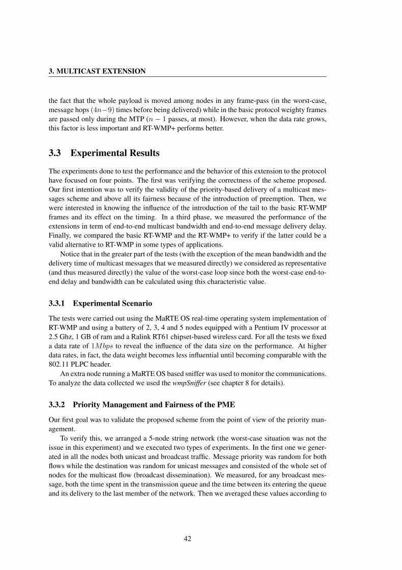
3. MULTICAST EXTENSION
the fact that the whole payload is moved among nodes in any frame-pass (in the worst-case,message hops (4n−9) times before being delivered) while in the basic protocol weighty framesare passed only during the MTP (n − 1 passes, at most). However, when the data rate grows,this factor is less important and RT-WMP+ performs better.
3.3 Experimental Results
The experiments done to test the performance and the behavior of this extension to the protocolhave focused on four points. The first was verifying the correctness of the scheme proposed.Our first intention was to verify the validity of the priority-based delivery of a multicast mes-sages scheme and above all its fairness because of the introduction of preemption. Then, wewere interested in knowing the influence of the introduction of the tail to the basic RT-WMPframes and its effect on the timing. In a third phase, we measured the performance of theextensions in term of end-to-end multicast bandwidth and end-to-end message delivery delay.Finally, we compared the basic RT-WMP and the RT-WMP+ to verify if the latter could be avalid alternative to RT-WMP in some types of applications.
Notice that in the greater part of the tests (with the exception of the mean bandwidth and thedelivery time of multicast messages that we measured directly) we considered as representative(and thus measured directly) the value of the worst-case loop since both the worst-case end-to-end delay and bandwidth can be calculated using this characteristic value.
3.3.1 Experimental Scenario
The tests were carried out using the MaRTE OS real-time operating system implementation ofRT-WMP and using a battery of 2, 3, 4 and 5 nodes equipped with a Pentium IV processor at2.5 Ghz, 1 GB of ram and a Ralink RT61 chipset-based wireless card. For all the tests we fixeda data rate of 1Mbps to reveal the influence of the data size on the performance. At higherdata rates, in fact, the data weight becomes less influential until becoming comparable with the802.11 PLPC header.
An extra node running a MaRTE OS based sniffer was used to monitor the communications.To analyze the data collected we used the wmpSniffer (see chapter 8 for details).
3.3.2 Priority Management and Fairness of the PME
Our first goal was to validate the proposed scheme from the point of view of the priority man-agement.
To verify this, we arranged a 5-node string network (the worst-case situation was not theissue in this experiment) and we executed two types of experiments. In the first one we gener-ated in all the nodes both unicast and broadcast traffic. Message priority was random for bothflows while the destination was random for unicast messages and consisted of the whole set ofnodes for the multicast flow (broadcast dissemination). We measured, for any broadcast mes-sage, both the time spent in the transmission queue and the time between its entering the queueand its delivery to the last member of the network. Then we averaged these values according to
42
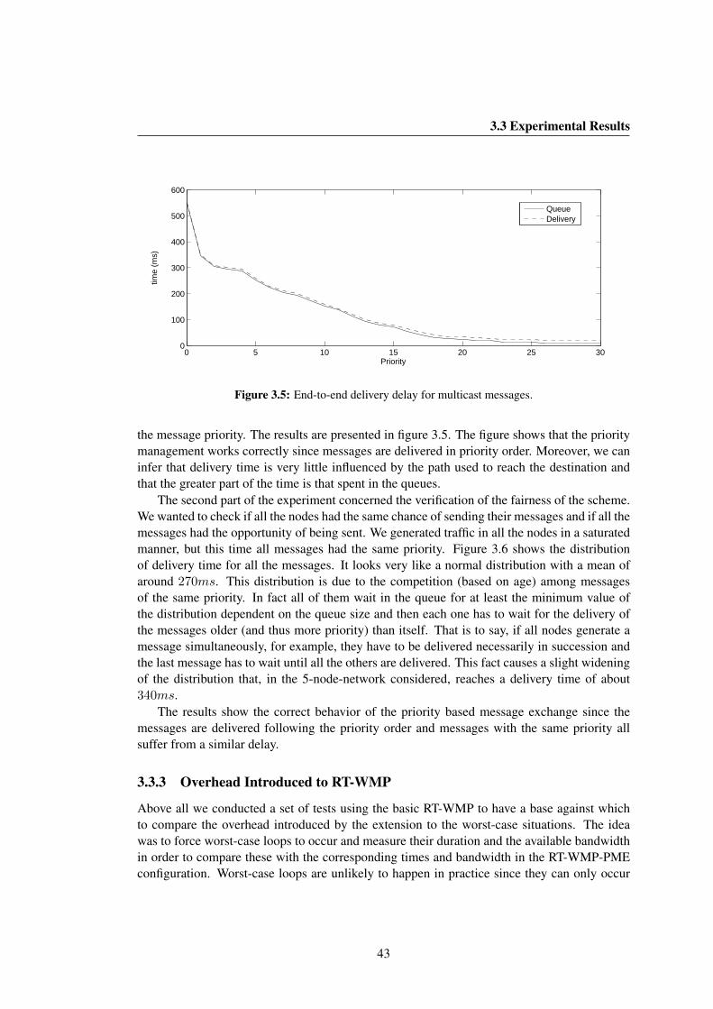
3.3 Experimental Results
0 5 10 15 20 25 300
100
200
300
400
500
600
Priority
time
(ms)
Queue Delivery
Figure 3.5: End-to-end delivery delay for multicast messages.
the message priority. The results are presented in figure 3.5. The figure shows that the prioritymanagement works correctly since messages are delivered in priority order. Moreover, we caninfer that delivery time is very little influenced by the path used to reach the destination andthat the greater part of the time is that spent in the queues.
The second part of the experiment concerned the verification of the fairness of the scheme.We wanted to check if all the nodes had the same chance of sending their messages and if all themessages had the opportunity of being sent. We generated traffic in all the nodes in a saturatedmanner, but this time all messages had the same priority. Figure 3.6 shows the distributionof delivery time for all the messages. It looks very like a normal distribution with a mean ofaround 270ms. This distribution is due to the competition (based on age) among messagesof the same priority. In fact all of them wait in the queue for at least the minimum value ofthe distribution dependent on the queue size and then each one has to wait for the delivery ofthe messages older (and thus more priority) than itself. That is to say, if all nodes generate amessage simultaneously, for example, they have to be delivered necessarily in succession andthe last message has to wait until all the others are delivered. This fact causes a slight wideningof the distribution that, in the 5-node-network considered, reaches a delivery time of about340ms.
The results show the correct behavior of the priority based message exchange since themessages are delivered following the priority order and messages with the same priority allsuffer from a similar delay.
3.3.3 Overhead Introduced to RT-WMP
Above all we conducted a set of tests using the basic RT-WMP to have a base against whichto compare the overhead introduced by the extension to the worst-case situations. The ideawas to force worst-case loops to occur and measure their duration and the available bandwidthin order to compare these with the corresponding times and bandwidth in the RT-WMP-PMEconfiguration. Worst-case loops are unlikely to happen in practice since they can only occur
43
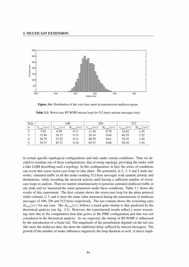
3. MULTICAST EXTENSION
150 200 250 300 350 4000
50
100
150
200
250
300
350
Delay (ms)
Occ
urre
nces
Figure 3.6: Distribution of the wait time spent in transmission multicast queue.
Table 3.1: Worst-case RT-WMP unicast loop for 512 bytes unicast messages (ms).
Size - 100 256 512n tloop(wc) tloop(wc) Rloop(wc) tloop(wc) Rloop(wc) tloop(wc) Rloop(wc)2 5.95 6.99 0.17 11.26 0.76 14.62 1.453 15.94 18.33 0.15 26.14 0.64 40.19 1.524 28.79 33.25 0.15 46.59 0.61 70.35 1.445 39.33 45.72 0.16 65.53 0.66 94.10 1.34
in certain specific topological configurations and only under certain conditions. Thus we de-cided to simulate one of these configurations, that of string topology, providing the nodes witha fake LQM describing such a topology. In this configuration, in fact, the series of conditionscan occur that cause worst-case loops to take place. We generated, in 2, 3, 4 and 5 node net-works, saturated traffic in all the nodes sending 512-byte messages with random priority anddestinations, while recording the network activity until having a sufficient number of worst-case loops to analyze. Then we started simultaneously to generate saturated multicast traffic inany node and we measured the same parameters under these conditions. Table 3.1 shows theresults of this experiment. The first column shows the worst-case loop for the plain protocolwhile columns 2, 3, and 4 show the same value measured during the transmission of multicastmessages of 100, 256 and 512 bytes respectively. The last column shows the worsening ratioRloop(wc) for any case. The Rloop(wc) follows a trend quite similar to that predicted by thetheoretical analysis (see fig. 3.3). However, the experimental results reflect a worst worsen-ing ratio due to the computation time that grows in the PME configuration and that was notconsidered in the theoretical analysis. As we expected, the timing of RT-WMP is influencedby the introduction of a frame tail. The magnitude of the perturbation depends on the tail size(the more the multicast data, the more the additional delay suffered by unicast messages). Thegrowth of the number of nodes influences negatively the loop duration as well. A direct impli-
44
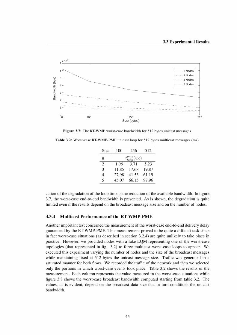
3.3 Experimental Results
0 100 256 5120
1
2
3
4
5
6
7x 10
5
Size (bytes)
Ban
dwid
th (
bps)
2 Nodes
3 Nodes
4 Nodes
5 Nodes
Figure 3.7: The RT-WMP worst-case bandwidth for 512 bytes unicast messages.
Table 3.2: Worst-case RT-WMP-PME unicast loop for 512 bytes multicast messages (ms).
Size 100 256 512
n tpmeloop(wc)
2 1.96 3.71 5.233 11.85 17.68 19.874 27.98 41.53 61.195 45.07 66.15 97.96
cation of the degradation of the loop time is the reduction of the available bandwidth. In figure3.7, the worst-case end-to-end bandwidth is presented. As is shown, the degradation is quitelimited even if the results depend on the broadcast message size and on the number of nodes.
3.3.4 Multicast Performance of the RT-WMP-PME
Another important test concerned the measurement of the worst-case end-to-end delivery delayguaranteed by the RT-WMP-PME. This measurement proved to be quite a difficult task sincein fact worst-case situations (as described in section 3.2.4) are quite unlikely to take place inpractice. However, we provided nodes with a fake LQM representing one of the worst-casetopologies (that represented in fig. 3.2) to force multicast worst-case loops to appear. Weexecuted this experiment varying the number of nodes and the size of the broadcast messageswhile maintaining fixed at 512 bytes the unicast message size. Traffic was generated in asaturated manner for both flows. We recorded the traffic of the network and then we selectedonly the portions in which worst-case events took place. Table 3.2 shows the results of themeasurement. Each column represents the value measured in the worst-case situations whilefigure 3.8 shows the worst-case broadcast bandwidth computed starting from table 3.2. Thevalues, as is evident, depend on the broadcast data size that in turn conditions the unicastbandwidth.
45
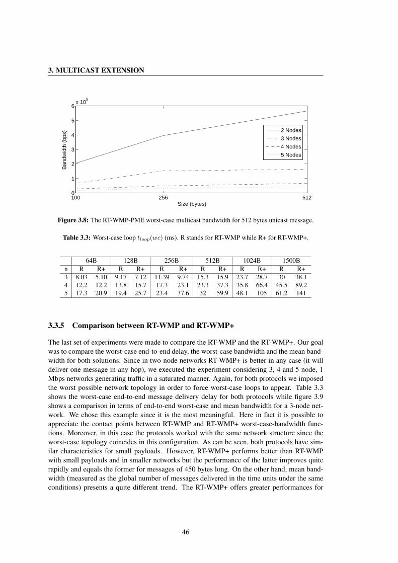
3. MULTICAST EXTENSION
100 256 5120
1
2
3
4
5
6x 10
5
Size (bytes)
Ban
dwid
th (
bps)
2 Nodes
3 Nodes
4 Nodes
5 Nodes
Figure 3.8: The RT-WMP-PME worst-case multicast bandwidth for 512 bytes unicast message.
Table 3.3: Worst-case loop tloop(wc) (ms). R stands for RT-WMP while R+ for RT-WMP+.
64B 128B 256B 512B 1024B 1500Bn R R+ R R+ R R+ R R+ R R+ R R+3 8.03 5.10 9.17 7.12 11.39 9.74 15.3 15.9 23.7 28.7 30 38.14 12.2 12.2 13.8 15.7 17.3 23.1 23.3 37.3 35.8 66.4 45.5 89.25 17.3 20.9 19.4 25.7 23.4 37.6 32 59.9 48.1 105 61.2 141
3.3.5 Comparison between RT-WMP and RT-WMP+
The last set of experiments were made to compare the RT-WMP and the RT-WMP+. Our goalwas to compare the worst-case end-to-end delay, the worst-case bandwidth and the mean band-width for both solutions. Since in two-node networks RT-WMP+ is better in any case (it willdeliver one message in any hop), we executed the experiment considering 3, 4 and 5 node, 1Mbps networks generating traffic in a saturated manner. Again, for both protocols we imposedthe worst possible network topology in order to force worst-case loops to appear. Table 3.3shows the worst-case end-to-end message delivery delay for both protocols while figure 3.9shows a comparison in terms of end-to-end worst-case and mean bandwidth for a 3-node net-work. We chose this example since it is the most meaningful. Here in fact it is possible toappreciate the contact points between RT-WMP and RT-WMP+ worst-case-bandwidth func-tions. Moreover, in this case the protocols worked with the same network structure since theworst-case topology coincides in this configuration. As can be seen, both protocols have sim-ilar characteristics for small payloads. However, RT-WMP+ performs better than RT-WMPwith small payloads and in smaller networks but the performance of the latter improves quiterapidly and equals the former for messages of 450 bytes long. On the other hand, mean band-width (measured as the global number of messages delivered in the time units under the sameconditions) presents a quite different trend. The RT-WMP+ offers greater performances for
46
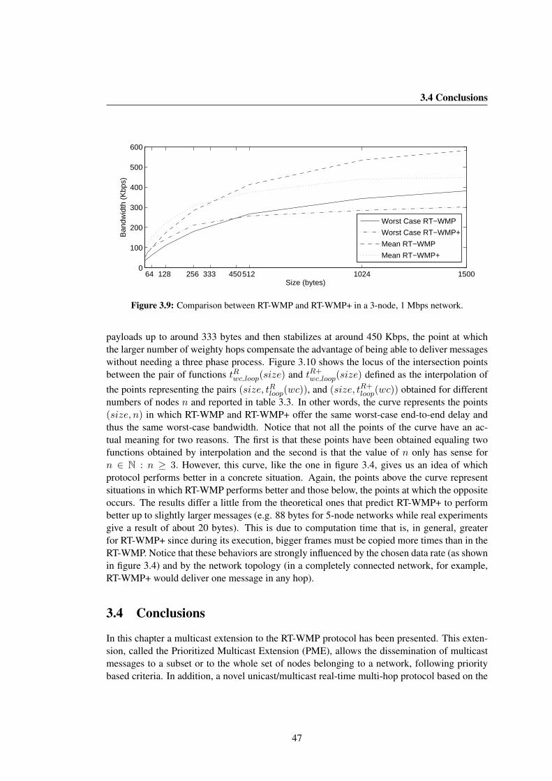
3.4 Conclusions
64 128 256 512 1024 1500333 450 0
100
200
300
400
500
600
Size (bytes)
Ban
dwid
th (
Kbp
s)
Worst Case RT−WMP
Worst Case RT−WMP+
Mean RT−WMP
Mean RT−WMP+
Figure 3.9: Comparison between RT-WMP and RT-WMP+ in a 3-node, 1 Mbps network.
payloads up to around 333 bytes and then stabilizes at around 450 Kbps, the point at whichthe larger number of weighty hops compensate the advantage of being able to deliver messageswithout needing a three phase process. Figure 3.10 shows the locus of the intersection pointsbetween the pair of functions tRwc loop(size) and tR+
wc loop(size) defined as the interpolation ofthe points representing the pairs (size, tRloop(wc)), and (size, tR+
loop(wc)) obtained for differentnumbers of nodes n and reported in table 3.3. In other words, the curve represents the points(size, n) in which RT-WMP and RT-WMP+ offer the same worst-case end-to-end delay andthus the same worst-case bandwidth. Notice that not all the points of the curve have an ac-tual meaning for two reasons. The first is that these points have been obtained equaling twofunctions obtained by interpolation and the second is that the value of n only has sense forn ∈ N : n ≥ 3. However, this curve, like the one in figure 3.4, gives us an idea of whichprotocol performs better in a concrete situation. Again, the points above the curve representsituations in which RT-WMP performs better and those below, the points at which the oppositeoccurs. The results differ a little from the theoretical ones that predict RT-WMP+ to performbetter up to slightly larger messages (e.g. 88 bytes for 5-node networks while real experimentsgive a result of about 20 bytes). This is due to computation time that is, in general, greaterfor RT-WMP+ since during its execution, bigger frames must be copied more times than in theRT-WMP. Notice that these behaviors are strongly influenced by the chosen data rate (as shownin figure 3.4) and by the network topology (in a completely connected network, for example,RT-WMP+ would deliver one message in any hop).
3.4 Conclusions
In this chapter a multicast extension to the RT-WMP protocol has been presented. This exten-sion, called the Prioritized Multicast Extension (PME), allows the dissemination of multicastmessages to a subset or to the whole set of nodes belonging to a network, following prioritybased criteria. In addition, a novel unicast/multicast real-time multi-hop protocol based on the
47
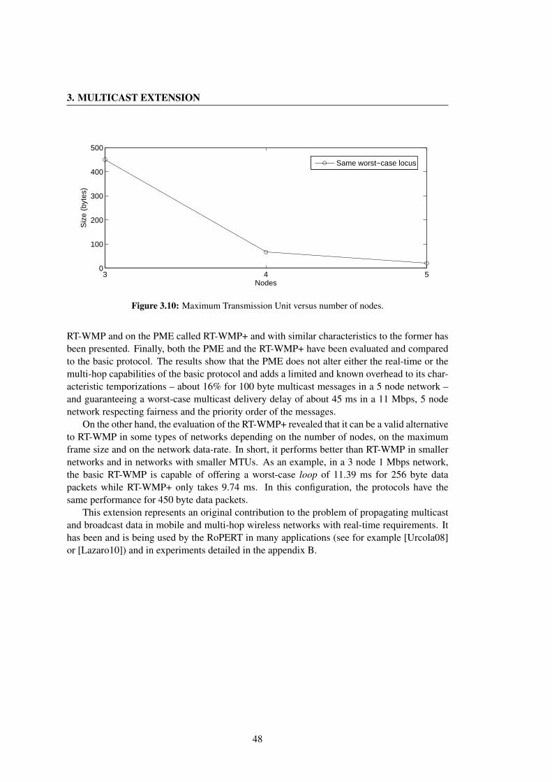
3. MULTICAST EXTENSION
3 4 50
100
200
300
400
500
Nodes
Siz
e (b
ytes
)
Same worst−case locus
Figure 3.10: Maximum Transmission Unit versus number of nodes.
RT-WMP and on the PME called RT-WMP+ and with similar characteristics to the former hasbeen presented. Finally, both the PME and the RT-WMP+ have been evaluated and comparedto the basic protocol. The results show that the PME does not alter either the real-time or themulti-hop capabilities of the basic protocol and adds a limited and known overhead to its char-acteristic temporizations – about 16% for 100 byte multicast messages in a 5 node network –and guaranteeing a worst-case multicast delivery delay of about 45 ms in a 11 Mbps, 5 nodenetwork respecting fairness and the priority order of the messages.
On the other hand, the evaluation of the RT-WMP+ revealed that it can be a valid alternativeto RT-WMP in some types of networks depending on the number of nodes, on the maximumframe size and on the network data-rate. In short, it performs better than RT-WMP in smallernetworks and in networks with smaller MTUs. As an example, in a 3 node 1 Mbps network,the basic RT-WMP is capable of offering a worst-case loop of 11.39 ms for 256 byte datapackets while RT-WMP+ only takes 9.74 ms. In this configuration, the protocols have thesame performance for 450 byte data packets.
This extension represents an original contribution to the problem of propagating multicastand broadcast data in mobile and multi-hop wireless networks with real-time requirements. Ithas been and is being used by the RoPERT in many applications (see for example [Urcola08]or [Lazaro10]) and in experiments detailed in the appendix B.
48
Chapter 4
QoS Extension
Nowadays, the widespread use of wireless devices confirms the need for supporting multimediatraffic. As a result, researchers have proposed several methods to offer some kind of Qualityof Service (QoS) in wireless scenarios both in infrastructure based networks and MANETs. Inrobotics, in general, these requirements are not so stringent. However, in some situations suchas rescue tasks involving humans (in the event of collapsed buildings or fire) the possibilityof establishing some type of communication with the victims (e.g. audio streaming) is veryuseful both for easing access to the disaster zone and obtaining information about the status ofthe persons involved. In other situations, (e.g. telemanipulation, access to inaccessible zones,etc.) visual information (like photo or video streaming) could be more effective.
In any case, under no circumstances should these additional flows of information jeopardizethe real-time behavior of the inter-robot communication network that is itself a critical issue.Since QoS flows have quite-strict time requirements and, at first sight, could be thought of asreal-time flows, it might therefore be considered to be a good idea to take into account theseflows at planning time and treat them as normal real-time flows.
However, on the one hand these flows are quite bandwidth consuming (even if some audio-streaming codec is capable of rates of about 3 Kbps, time requirements can force to keep awider bandwidth) and in some specific situations might not be possible (depending on thesaturation of the real-time bandwidth) while, on the other hand, not all the frames necessarilyhave to be delivered. As an example, the iLBC [Andersen02] or speex [SPEEX09] audio codecsguarantee, at low bit rate, a Mean Opinion Square (MOS) greater than 3.3 and 2.5 respectivelywith a packet delivery ratio (PDR) of about 95% while speex is capable of guaranteeing a MOSvalue above 2.5 for a PDR of about 85%. On the one hand, then, it seems there is little sense touse real-time bandwidth to transport information that does not have these characteristics whileon the other hand there are certain situations in which we need these types of flows.
In this chapter we propose a novel solution to incorporate QoS support in real-time token-passing wireless communication protocols without jeopardizing the worst-case end-to-end de-lay. This idea has been implemented and analyzed as an extension of the RT-WMP protocol butcan be conceptually used in any other token-passing solution. The rationale is to take advantageof the bandwidth left free by the protocol when it is not working in the worst-case situation anduse it to send QoS frames to allow audio and video streaming flows.
49

4. QOS EXTENSION
This contribution has been developed within the framework of the NERO Spanish NationalProject and the European Commission URUS project. The results of this work were presentedat the First International Conference on Ad-hoc Networks held from September 23 to 25, 2009in Niagara Falls, Ontario, Canada and published in “Ad-hoc Networks, Lecture Notes of the In-stitute for Computer Sciences, Social Informatics and Telecommunications Engineering” withthe title “QoS over Real-Time Wireless Multi-hop Protocol” [Sicignano10a].
4.1 Related Work
The problem of offering QoS guarantees in wireless networks has been studied in depth inrecent years thanks to the growing interest in offering multimedia contents in infrastructurebased and MANET networks. Protocols like 802.11e [IEEE05], for example, try to introducea certain degree of determinism at the MAC layer prioritizing traffic as a function of its typeand class. Other researchers have proposed interesting solutions for offering QoS guaranteesover multi-hop networks modifying this protocol. This is the case of [Hamidian07] where theauthors add a QoS mechanism to the enhanced distributed channel access (EDCA) scheme toallow a resource reservation or [Reddy07] where packets are prioritized using a combination ofthe laxity of the packet and the number of hops to the destination node to give higher priorityto the packets that have to traverse many hops.
Other solutions are based on a token-passing scheme and implement similar MAC oper-ations. The network generates a unique token that permits only the node currently holdingit to transmit data. In [Ergen03] the potential of achieving higher channel utilization using atoken scheme compared to CSMA based schemes is shown. More recently, in [Wang07], theadvantage of a token-passing scheme over contention based and centralized polling schemes toprovide guaranteed priority for different traffic classes in WLAN has been analyzed. A similaranalysis is conduced in [Zhang08] which shows how a token ring scheme applied in vehicu-lar ad-hoc networks can outperform IEEE 802.11 DCF in terms of average throughput. Thewireless dynamic token protocol (WDTP) [Zhai06] modifies the method to control the tokentransfer scheme of the WTRP. All nodes are clustered into subnets and the nodes of a subnetshare a channel. This improves the adaptability to the network topology but the number ofused channels increases. Some proposals are based on hybrid MAC Token CDMA policingmechanisms. Taheri and Scaglione’s [Taheri02] proposal is based on a ring network whereeach token corresponds to a physical CDMA subchannel which is guaranteed to have a certainaverage rate and satisfies a probability of error bound by identifying two classes of service togive prority to QoS traffic.
All these solutions, despite offering some degree of timing guarantees, have a quite differ-ent target than the solution proposed in this chapter, since the only objective is to offer QoSsupport without considering the real-time requirements. Currently, to the best of our knowl-edge, there is no protocol that allows the simultaneous transportation of real-time and QoStraffic.
50
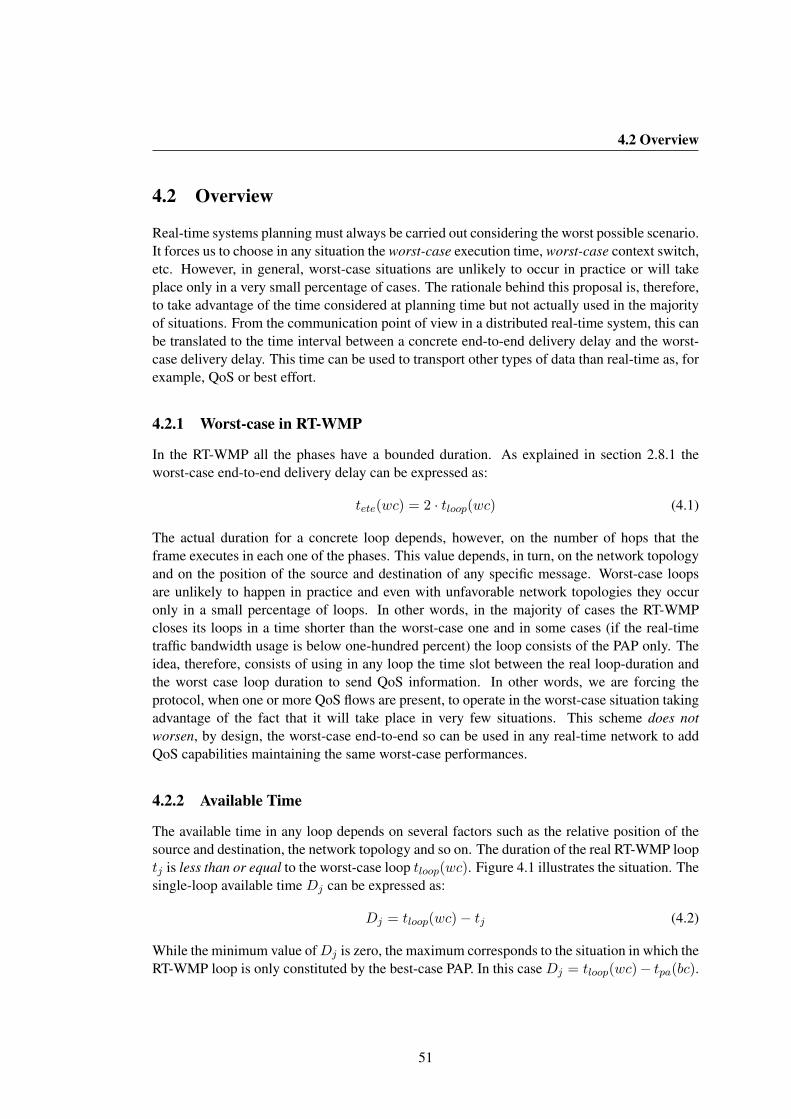
4.2 Overview
4.2 Overview
Real-time systems planning must always be carried out considering the worst possible scenario.It forces us to choose in any situation the worst-case execution time, worst-case context switch,etc. However, in general, worst-case situations are unlikely to occur in practice or will takeplace only in a very small percentage of cases. The rationale behind this proposal is, therefore,to take advantage of the time considered at planning time but not actually used in the majorityof situations. From the communication point of view in a distributed real-time system, this canbe translated to the time interval between a concrete end-to-end delivery delay and the worst-case delivery delay. This time can be used to transport other types of data than real-time as, forexample, QoS or best effort.
4.2.1 Worst-case in RT-WMP
In the RT-WMP all the phases have a bounded duration. As explained in section 2.8.1 theworst-case end-to-end delivery delay can be expressed as:
tete(wc) = 2 · tloop(wc) (4.1)
The actual duration for a concrete loop depends, however, on the number of hops that theframe executes in each one of the phases. This value depends, in turn, on the network topologyand on the position of the source and destination of any specific message. Worst-case loopsare unlikely to happen in practice and even with unfavorable network topologies they occuronly in a small percentage of loops. In other words, in the majority of cases the RT-WMPcloses its loops in a time shorter than the worst-case one and in some cases (if the real-timetraffic bandwidth usage is below one-hundred percent) the loop consists of the PAP only. Theidea, therefore, consists of using in any loop the time slot between the real loop-duration andthe worst case loop duration to send QoS information. In other words, we are forcing theprotocol, when one or more QoS flows are present, to operate in the worst-case situation takingadvantage of the fact that it will take place in very few situations. This scheme does notworsen, by design, the worst-case end-to-end so can be used in any real-time network to addQoS capabilities maintaining the same worst-case performances.
4.2.2 Available Time
The available time in any loop depends on several factors such as the relative position of thesource and destination, the network topology and so on. The duration of the real RT-WMP looptj is less than or equal to the worst-case loop tloop(wc). Figure 4.1 illustrates the situation. Thesingle-loop available time Dj can be expressed as:
Dj = tloop(wc)− tj (4.2)
While the minimum value ofDj is zero, the maximum corresponds to the situation in which theRT-WMP loop is only constituted by the best-case PAP. In this case Dj = tloop(wc)− tpa(bc).
51
4. QOS EXTENSION
t j D j RT-WMP Loop
Loop Startt loop(wc)
Figure 4.1: Time intervals used by the QoS Extension.
4.2.3 Protocol Overview
To each node has been added a QoS transmission and reception queue (QTQ and QRQ respec-tively). Each QoS message has a deadline that is fixed by the application and that representsthe time during which the message is valid.
The QoS extension has three phases: an arbitration phase, a QoS Authorization Phase(QAP) and a QoS Message Phase (QMP). The last two phases can be repeated one after theother for a limited number of times (fixed at compile time). The arbitration phase is carried outduring the PAP while the QAP and QMP are added to the basic protocol.
During the arbitration phase all the nodes which have a QoS message waiting in the QTQcompete to gain the right to send it (remember that during the PAP the token reaches all thenodes). One or more messages can be selected for transmission depending on their deadlineand on the distance between the source and the destination nodes, as will be explained below.The first QAP starts when the standard MTP ends or after the PAP if there are no real-timemessages to send. The node which ends the MTP (or the PAP), instead of restarting the succes-sive PAP, sends an authorization to the owner of the first selected QoS message indicated in theheader, through the same procedure used by the basic RT-WMP. When the latter receives theauthorization, it starts the QMP and sends the QoS message to the destination node. Succes-sively, if there are other QoS messages to send, it prepares an authorization and starts anotherQAP during which the authorization reaches the node owner of the selected message. This,in turn, sends its message during a further QMP and so on. As has been stated, the QAP andQMP are repeated one after the other for a limited (and configurable) number of times, but inany case they stop when the worst-case loop time is reached.
The QoS extension implements eight flow classes where class zero corresponds to best-effort not-QoS traffic (infinite deadline). Flows are served following their class level. Audioflows, for example, usually have priority over video flows since audio information is moredelay sensitive. The introduction of a flow in the protocol is regulated by the Flow AdmissionControl (FAC) that allows or denies access, taking into account the priority of the requestingflow and the available bandwidth for QoS flows estimated by analysing the difference betweenthe duration of worst-case and real loops within a certain time-window.
52

4.2 Overview
RT-WMP Frame
qos_rem qos_dlqos_src qos_prioqos_dstac_art ac_pri ac_lot1 x n12 12 2 x n1 x n 1 x n
TailHeader
Figure 4.2: Frame of the RT-WMP with QoS extension.
4.2.4 Frame Header Extension
Figure 4.2 shows the RT-WMP frame with the fields added to give support to the QoS extension.The qos rem field is a 2 byte field that is filled, at the beginning of any loop, with the worst-case RT-WMP loop duration expressed in milliseconds. The ac loop id, ac pri, and ac lot areservice fields used by the access control system to estimate the available QoS bandwidth. Thenext fields are used to identify the selected messages. All of them are (compile-time) con-figurable size vectors. Their size is application and network-size dependent and correspondsto the maximum number N MSG of QoS messages that can be selected (and potentially deliv-ered) in any loop. The qos dl (2 bytes per message) contains the present deadline of the packets(relative deadline to the present moment) while the qos src and qos dst (1 byte per message)specify their source and destination. These last three fields are used to calculate the dynamicpriority of the message that depends on the deadline and the distance between the source anddestination of a message. The last qos pri field (1 byte per message) carries the priority classof the selected message.
4.2.5 Phases of the Protocol
In this section a detailed description of the different phases of the protocol is presented includ-ing some implementation issues than conditioned the development of the protocol.
QoS Arbitration Phase
The first phase of the protocol takes place simultaneously with the PAP of the basic RT-WMPwithout altering the operations of the basic protocol (tokens are exchanged in the usual way).In this phase, the QoS messages to be transmitted in the successive phases are selected. In eachnode the QTQ contains all the QoS messages ordered by priority (see sec. 4.2.6). The node thatstarts the PAP analyses its QTQ. Above all, it discards the expired messages. Then, it obtainsthe class flow, the deadline and the destination of the N MSG most priority messages and fillsthe corresponding fields of the vector in the token header (qos dl, qos src, etc.). Moreover, itcalculates the worst-case loop duration and fills the field qos rem of the header with this valueexpressed in milliseconds. Successively the basic protocol is responsible for sending the tokento another node. The node that receives the token processes the basic part of the token as usual.Then, it actualizes the values of qos rem and the qos dl subtracting the time spent in the last
53

4. QOS EXTENSION
token-pass. It successively calculates the new priority for the messages referenced by the token.This step is necessary because the change in the deadline could imply a change in priority aswill be explained later. It then again discards expired messages and compares the N MSG mostpriority messages in its QTQ with those carried by the token. If it figures out that it owns oneor more message with higher priority, it replaces the less priority with its/their own, updatingthe qos dl, qos src and the qos dst field(s).
In the same way, the process is repeated up to the moment in which the last node of thenetwork is reached. At this moment the node starts the ATP and the MTP (if real-time mes-sages have been selected to be sent). In these two phases, there is no participation of the QoSextension except for the fact that the qos dl and qos rem fields are decreased by the quantitycorresponding to the time spent in any frame pass.
QoS Authorization Phase
This phase starts after the conclusion of the MTP (if any) or the PAP, or even after a QMP.The node that starts the QAP prepares an authorization as in the basic protocol, fills the aut srcwith its address and aut dest with the first element of the qos dst vector, shifts by one theposition of the qos dst, qos dl, qos pri and qos src vector elements (qos dl[0]=qos dl[1],qos src[0]=qos src[1], etc.) and sends the frame.
The authorization is propagated using the same routing algorithm of the basic protocol untilit reaches the destination. In any hop, however, the qos dl and qos rem fields are actualizedsubtracting the duration of any frame-pass. If at some moment the qos rem field reaches avalue that does not allow a further frame-pass, the QAP is immediately aborted and a new PAPis started.
QoS Message Phase
When a node receives a QoS Authorization, the QMP starts. It pops the most priority messagefrom the QTQ and creates a new message frame placing data in the message field. It fills the srcand dest fields with its address and with the destination address while the age field is filled withthe deadline of the message. Then it calculates the path to the destination and sends the messageto the first member of the path as in the RT-WMP basic protocol. When the latter receives themessage, it actualizes the qos dl, qos rem and age fields, subtracting the time spent in the lastmessage pass and then it checks the msg dest field. If it is not the destination node (i.e. it is anintermediate node), it verifies if there is enough remaining time to forward the message to thenext node of the path (i.e. the value of qos rem is at least greater than the time needed for onemessage-hop). If this is the case, the node repeats the computation of the path and routes themessage to the next member of the path, leaving the dest field unchanged. Otherwise, it pushesthe message into the QoS transmission queue (using the value of the age field as the deadlinefor the message) and starts a new PAP. In this case the message will compete to be selected fortransmission again in the next PAP. When the node receives the QoS message, it pushes it intothe QRQ. If the message reaches the destination in a single loop, there is the chance of sendinganother QoS message. The receiver then looks at the qos rem field. If it is assured that there isenough time to authorize another node and to allow at least one message-hop, it starts another
54
4.3 Flow Admission Control
QAP that, in turn, will cause another QMP and so on until reaching a maximum of N MSGQMP phases.
4.2.6 Message Priority Policy
A QoS message must be delivered before its deadline or it is useless. The QoS routing protocolmust therefore be aware of this fact and act to avoid as much discard as possible. In themajority of QoS protocols, the deadline represents the priority of the message: the nearer thedeadline, the higher the priority. This scheme however, does not take into account the distancebetween the source node and the destination node while it is evident that two messages withthe same deadline but with different paths (length) to the destination should be treated in adifferent manner. The message that has more hops to travel, in fact, has less probability ofbeing delivered.
The QoS extension implements a packet scheduler that assigns a dynamic priority to apacket taking into account the flow class, the deadline and the number of hops left to thedestination as proposed in [Reddy07]. Above all, the scheduler sorts the packets according totheir flow class. Messages in the same flow-class are sorted using the laxity that is a parameterthat combines the deadline and the number of hops left to the destination as:
laxity =deadline
hopleft(4.3)
The laxity gives us an estimation of how much delay the packet can tolerate at each hop. Hence,the packet with the lowest value of laxity is given the highest priority. If two packets have thesame lowest value of laxity, we resolve the conflict by sending the packet which has more hopsto travel. If the laxity value becomes zero (↔ deadline = 0), the packet is discarded since itis useless at the destination.
4.3 Flow Admission Control
The available bandwidth for QoS flows is limited and depends on different factors such asreal-time traffic saturation, network topology and so on. Thus, it is important to control theadmission of new QoS flows in a real-time network since if the available bandwidth is notenough, it is possible to jeopardize the correct working of already present QoS flows. As anexample, consider the situation in which in the network already exists a 15 Kbps flow and theglobal available bandwidth for QoS flow is 20 Kbps. If we try to introduce another 15 Kbpsflow of the same class, the system will distribute the available bandwidth between the twoflows lowering the rate of both to 10 Kbps discarding the messages that cannot be deliveredwithin the deadline. It would not be enough for a correct streaming and both flows would beuseless. To avoid these problems we have developed a Flow Admission Control (FAC) systemthat estimates and manages the available bandwidth. The idea is to compute if there is enoughbandwidth for a given new flow.
55

4. QOS EXTENSION
4 3 2 8 4
ABEI
4 3 2 8 4
GRTGURT GART
4 8 4
GRTART(4)
3 2
1
Free Time
RT-WMP Loop
4 QoS Flow (class)a)
c)b)
Loop Start
Figure 4.3: Resource estimation mechanism.
4.3.1 Available Resource Estimation
To estimate the available bandwidth for new QoS flows, the network is observed during atime window that contains several RT-WMP loops. We call this sliding window the AvailableBandwidth Estimation Interval (ABEI). The width of the ABEI is configurable and a goodchoice is usually related to the hyperperiod of the underlying real-time distributed system.
Over an ABEI the Global Remaining Time (GRT) is calculated as:
GRT =∑
j:loopjεABEI
Dj (4.4)
The GRT represents the sum of all the remaining time Dj that is included in the ABEI. Inother words, the GRT is a raw measurement of the available time for QoS flows.
Any QoS flow occupies a portion of this global available time. We call the sum of all theoccupied portions Global Used Remaining Time (GURT) that can be expressed as:
GURT =∑
j:loopjεABEI,kε[0..7]
tdj(k) (4.5)
tdj(k) being the time consumed by a k class flow in a j loop (see fig. 4.3). In a similarway it is possible to define the Global Available Remaining Time (GART) as:
GART = GRT −GURT (4.6)
The GART represents the time still available subtracting the time occupied by already-activeQoS flows. However, this access control scheme relies on flow classes, that is, higher priorityflows can expel lower priority ones. In the light of this, the GART can be considered as theavailable time for the least-priority flow in the system at any moment. The available time for agiven class flow is instead called the Available Remaining Time (ART). It can be expressed as:
ART (c) = GRT −∑
j:loopjεABEI,k≥ctdj(k) (4.7)
c being the class of the flow that is requesting access. If a flow requests access to the system, the
56

4.3 Flow Admission Control
20 40 60 800
1000
2000
3000
4000
Occ
urre
nces
(ms)
TWC
Dmean
= 61.7520 30 40 50 60 70 80 900
100
200
300
400
(ms)O
ccur
renc
es
WCT
= 29.76Dmean
20 30 40 50 60 70 80 90
0
200
400
600
800
(ms)
Occ
urre
nces
TWC
D mean= 30.88
1p 2p
3p
4p6p
5p
a)
1p 2p 3p 4p 5p 6p
b)
1p3p
5p
2p
6p
4p
c)
Figure 4.4: Time spent for the RT-WMP in real test compared to worst-case for different topolo-gies.
FAC calculates the ART for the class flow of the flow requesting access and estimates (using asimple heuristic) whether there is enough bandwidth to allow the access.
4.3.2 Principle of Operations
When a node closes a MTP (or a PAP if there are no real-time messages to send), it stores in alocal vector the value of qos rem together with a timestamp. Next, it fills the ac lot field withthe value of the qos rem field. Successively, when a QoS message is delivered, if k is the classflow of the message, the receiver computes the time spent to deliver the last message with theformula:
td(k) = ac lot− qos rem (4.8)
The node stores td in a local vector together with the class of the message just receivedagain with a timestamp. Then it actualizes the value of the ac lot with the present value ofqos rem and continues the operations with another QAP or a new PAP. The process is repeatedin any loop and the nodes accumulate, but in a distributed fashion, all the information aboutmessage delivery times and remaining times. In fact, none of the nodes has a global view ofthe available time in the network. However, the sum of all the elements of the first vector of allthe nodes whose timestamp is contained in the ABEI window represents the GRT and the sumof all the elements of the second vector whose timestamp is contained in the ABEI windowrepresents just the time consumed by all the active flows (the GURT).
When a node needs to add a new flow into the network, it makes a request specifyingthe class of the new flow in the ac pri field (that normally contains a negative value). In thesuccessive PAP, all the nodes analyse their local vectors with respect to the values stored inthe ABEI window. Specifically they sum all the values of the first vector whose timestamp is
57
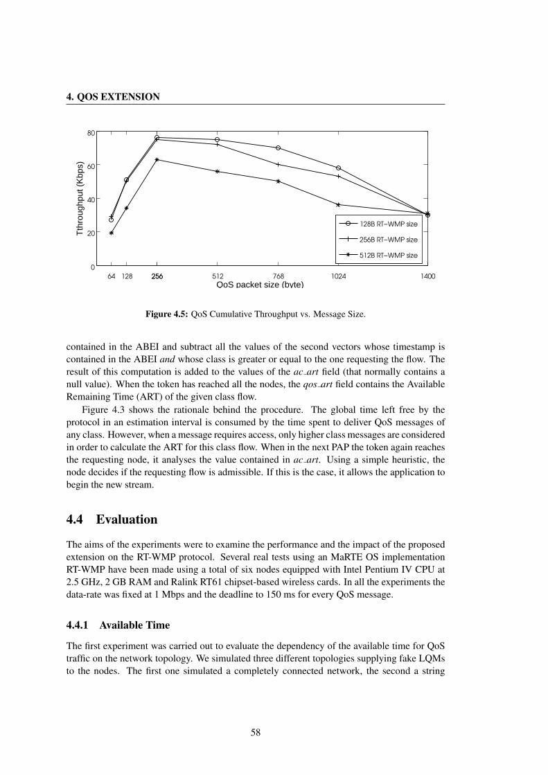
4. QOS EXTENSION
64 128 256256 512 768 1024 1400
0
20
40
60
80
QoS packet size (byte)
Tth
roug
hput
(K
bps)
128B RT−WMP size
256B RT−WMP size
512B RT−WMP size
Figure 4.5: QoS Cumulative Throughput vs. Message Size.
contained in the ABEI and subtract all the values of the second vectors whose timestamp iscontained in the ABEI and whose class is greater or equal to the one requesting the flow. Theresult of this computation is added to the values of the ac art field (that normally contains anull value). When the token has reached all the nodes, the qos art field contains the AvailableRemaining Time (ART) of the given class flow.
Figure 4.3 shows the rationale behind the procedure. The global time left free by theprotocol in an estimation interval is consumed by the time spent to deliver QoS messages ofany class. However, when a message requires access, only higher class messages are consideredin order to calculate the ART for this class flow. When in the next PAP the token again reachesthe requesting node, it analyses the value contained in ac art. Using a simple heuristic, thenode decides if the requesting flow is admissible. If this is the case, it allows the application tobegin the new stream.
4.4 Evaluation
The aims of the experiments were to examine the performance and the impact of the proposedextension on the RT-WMP protocol. Several real tests using an MaRTE OS implementationRT-WMP have been made using a total of six nodes equipped with Intel Pentium IV CPU at2.5 GHz, 2 GB RAM and Ralink RT61 chipset-based wireless cards. In all the experiments thedata-rate was fixed at 1 Mbps and the deadline to 150 ms for every QoS message.
4.4.1 Available Time
The first experiment was carried out to evaluate the dependency of the available time for QoStraffic on the network topology. We simulated three different topologies supplying fake LQMsto the nodes. The first one simulated a completely connected network, the second a string
58

4.4 Evaluation
10 25 50 75 100
60
80
100
120
RT−WMP load (%)
QoS
cum
ulat
ive
thro
ughp
ut (
Kbp
s)
Figure 4.6: QoS Cumulative Throughput vs. RT-WMP load percentile.
and the last a star. In the last two configurations, worst-case loops can occur while in thefirst of them all are best-case loops. Nodes were forced to generate saturated real-time trafficwith random destinations and message size. Figure 4.4 shows the result. In figure 4.4.a wecan observe that the connected topology leaves a mean of Dj = 61.75 ms available for QoStraffic considering a worst-case loop of about tloop(wc) = 78 ms, that is about 80% of thetime. Both the string and the star topology are quite demanding leaving a mean of aboutDj = 30 ms (38%). These results are promising and lead us to expect a good performancefrom the extension.
4.4.2 Message size and Traffic impact
The aim of the second experiment was to consider the impact of the real-time and QoS messagesize on QoS traffic. To analyze this, we generated five 15 Kbps QoS flows varying the QoSmessage size in a string network. At the same time we saturated the network with real-timetraffic of different message size. Figure 4.5 shows the results. As expected, the QoS trafficshows a dependency on the real-time traffic message size that moves the graph in the y-axis.On the other hand, the shape of the graphic is due to the fact that small size messages increasethe relative weight of authorization phases with negative consequences for efficiency while bigpackets have less probability of being delivered, especially over long paths due to the timeneeded to propagate them (remember that the network rate is 1 Mbps).
After that we reduced progressively the real-time traffic load from 100% to 10% leavingthe QoS flows to grow as much as they could to evaluate the dependency of the extension onthis parameter. Figure 4.6 shows an almost linear dependency. As expected, a lower RT-WMPload benefits the QoS throughput
59
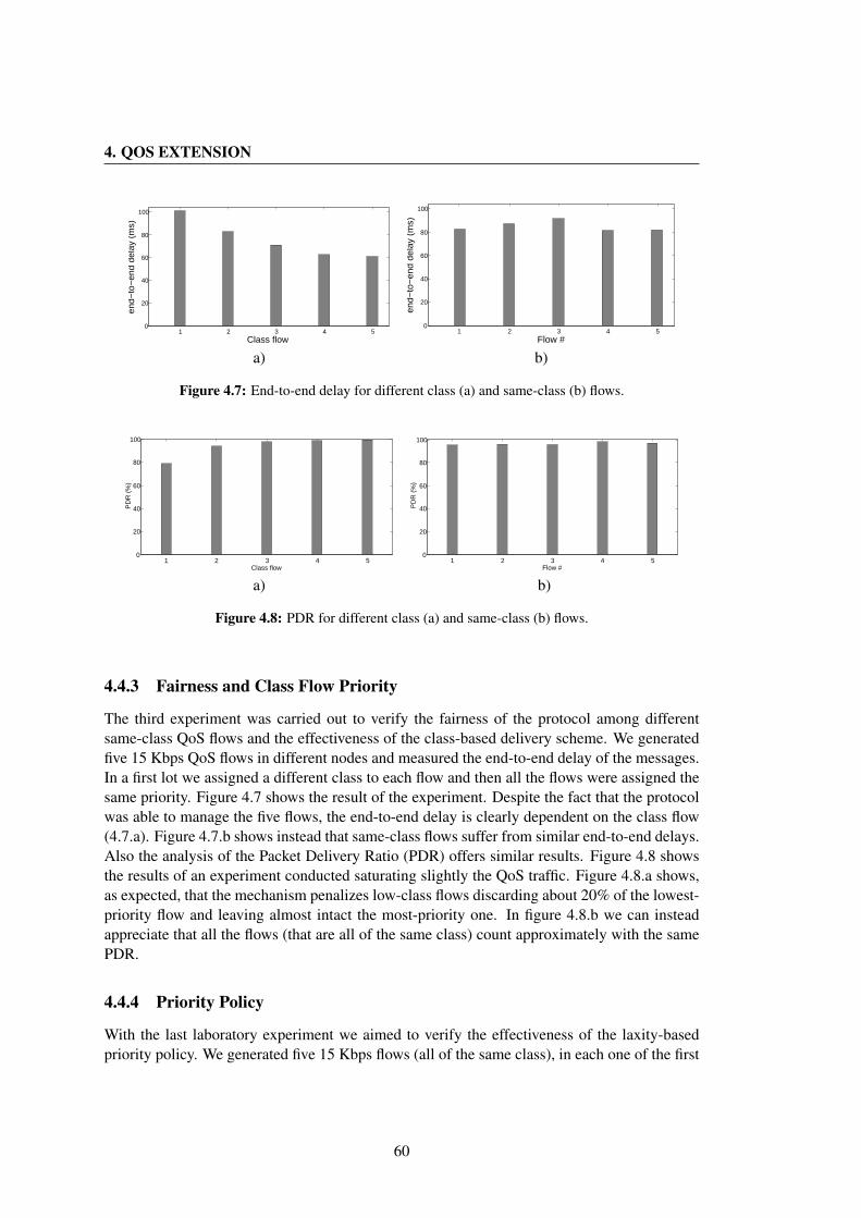
4. QOS EXTENSION
1 2 3 4 50
20
40
60
80
100
end−
to−
end
dela
y (m
s)
Class flow 1 2 3 4 5
0
20
40
60
80
100
Flow #
end−
to−
end
dela
y (m
s)
a) b)
Figure 4.7: End-to-end delay for different class (a) and same-class (b) flows.
1 2 3 4 50
20
40
60
80
100
Class flow
PD
R (
%)
1 2 3 4 50
20
40
60
80
100
Flow #
PD
R (
%)
a) b)
Figure 4.8: PDR for different class (a) and same-class (b) flows.
4.4.3 Fairness and Class Flow Priority
The third experiment was carried out to verify the fairness of the protocol among differentsame-class QoS flows and the effectiveness of the class-based delivery scheme. We generatedfive 15 Kbps QoS flows in different nodes and measured the end-to-end delay of the messages.In a first lot we assigned a different class to each flow and then all the flows were assigned thesame priority. Figure 4.7 shows the result of the experiment. Despite the fact that the protocolwas able to manage the five flows, the end-to-end delay is clearly dependent on the class flow(4.7.a). Figure 4.7.b shows instead that same-class flows suffer from similar end-to-end delays.Also the analysis of the Packet Delivery Ratio (PDR) offers similar results. Figure 4.8 showsthe results of an experiment conducted saturating slightly the QoS traffic. Figure 4.8.a shows,as expected, that the mechanism penalizes low-class flows discarding about 20% of the lowest-priority flow and leaving almost intact the most-priority one. In figure 4.8.b we can insteadappreciate that all the flows (that are all of the same class) count approximately with the samePDR.
4.4.4 Priority Policy
With the last laboratory experiment we aimed to verify the effectiveness of the laxity-basedpriority policy. We generated five 15 Kbps flows (all of the same class), in each one of the first
60
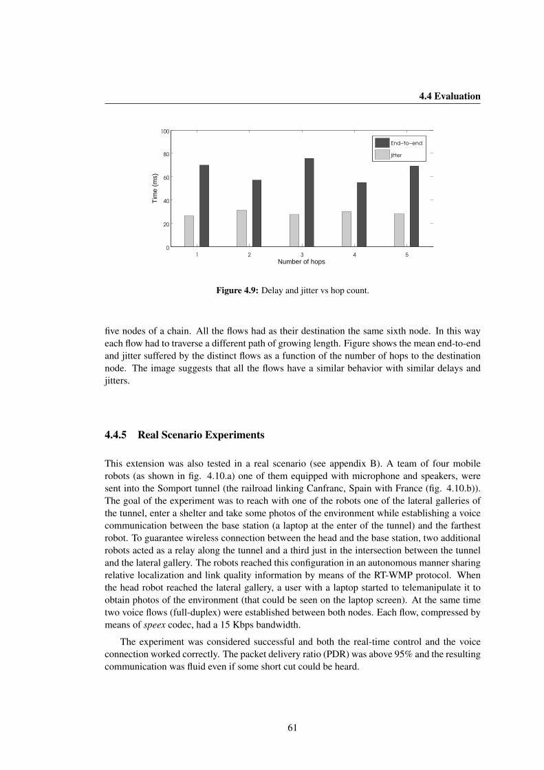
4.4 Evaluation
1 2 3 4 5
0
20
40
60
80
100
Number of hops
Tim
e (m
s)
End−to−end
jitter
Figure 4.9: Delay and jitter vs hop count.
five nodes of a chain. All the flows had as their destination the same sixth node. In this wayeach flow had to traverse a different path of growing length. Figure shows the mean end-to-endand jitter suffered by the distinct flows as a function of the number of hops to the destinationnode. The image suggests that all the flows have a similar behavior with similar delays andjitters.
4.4.5 Real Scenario Experiments
This extension was also tested in a real scenario (see appendix B). A team of four mobilerobots (as shown in fig. 4.10.a) one of them equipped with microphone and speakers, weresent into the Somport tunnel (the railroad linking Canfranc, Spain with France (fig. 4.10.b)).The goal of the experiment was to reach with one of the robots one of the lateral galleries ofthe tunnel, enter a shelter and take some photos of the environment while establishing a voicecommunication between the base station (a laptop at the enter of the tunnel) and the farthestrobot. To guarantee wireless connection between the head and the base station, two additionalrobots acted as a relay along the tunnel and a third just in the intersection between the tunneland the lateral gallery. The robots reached this configuration in an autonomous manner sharingrelative localization and link quality information by means of the RT-WMP protocol. Whenthe head robot reached the lateral gallery, a user with a laptop started to telemanipulate it toobtain photos of the environment (that could be seen on the laptop screen). At the same timetwo voice flows (full-duplex) were established between both nodes. Each flow, compressed bymeans of speex codec, had a 15 Kbps bandwidth.
The experiment was considered successful and both the real-time control and the voiceconnection worked correctly. The packet delivery ratio (PDR) was above 95% and the resultingcommunication was fluid even if some short cut could be heard.
61
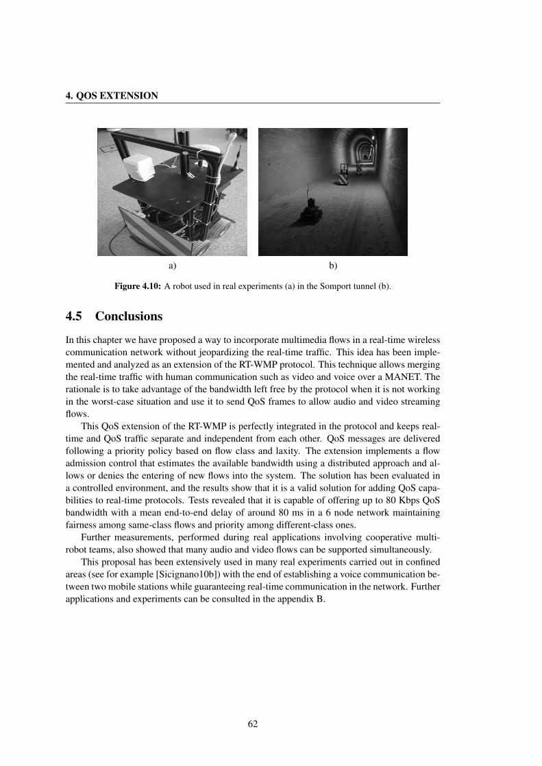
4. QOS EXTENSION
a) b)
Figure 4.10: A robot used in real experiments (a) in the Somport tunnel (b).
4.5 Conclusions
In this chapter we have proposed a way to incorporate multimedia flows in a real-time wirelesscommunication network without jeopardizing the real-time traffic. This idea has been imple-mented and analyzed as an extension of the RT-WMP protocol. This technique allows mergingthe real-time traffic with human communication such as video and voice over a MANET. Therationale is to take advantage of the bandwidth left free by the protocol when it is not workingin the worst-case situation and use it to send QoS frames to allow audio and video streamingflows.
This QoS extension of the RT-WMP is perfectly integrated in the protocol and keeps real-time and QoS traffic separate and independent from each other. QoS messages are deliveredfollowing a priority policy based on flow class and laxity. The extension implements a flowadmission control that estimates the available bandwidth using a distributed approach and al-lows or denies the entering of new flows into the system. The solution has been evaluated ina controlled environment, and the results show that it is a valid solution for adding QoS capa-bilities to real-time protocols. Tests revealed that it is capable of offering up to 80 Kbps QoSbandwidth with a mean end-to-end delay of around 80 ms in a 6 node network maintainingfairness among same-class flows and priority among different-class ones.
Further measurements, performed during real applications involving cooperative multi-robot teams, also showed that many audio and video flows can be supported simultaneously.
This proposal has been extensively used in many real experiments carried out in confinedareas (see for example [Sicignano10b]) with the end of establishing a voice communication be-tween two mobile stations while guaranteeing real-time communication in the network. Furtherapplications and experiments can be consulted in the appendix B.
62
Chapter 5
Alien Traffic Endurance
The diffusion of wireless devices has been very fast in recent years owing to their flexibilityand low cost. Wireless solutions are used in many areas, from remote control to Internet access.This latter use is very common and it is possible nowadays, thanks to the wide acceptance ofthe 802.11 standard (in all its forms), to find many wireless networks in the same area interfer-ing with each other in the same or adjacent channels. In order to avoid collisions the CarrierSense Multiple Access with Collision Avoidance (CSMA/CA) technique is used which, nev-ertheless, is not 100% effective. Supporting real-time communication in such a scenario is avery challenging task since it is very difficult to have guarantees about the bandwidth on whichthe real-time network can rely at any moment. On the other hand, there are situations in whichthe channel bandwidth must be shared with other networks, meaning that there are nodes (aliennodes) that transmit valid frames (alien frames) that, nevertheless, do not comply with the spe-cific rules of the real-time protocol. This is the case, for example, in the RoboCup competition[Santos09] where two robotic-soccer teams have to share the same wireless channel since bothuse the same access point to connect the team members.
In this chapter we propose a solution to alleviate this problem and allow token-passing-based real-time wireless protocols to work in the presence of alien traffic, offering timing guar-antees by means of the use of a variable acknowledgement timeout that increases in the pres-ence of alien traffic and allows belated acknowlegments to be accepted also. We have appliedthis solution to the RT-WMP and tested it in real environments to evaluate the effectiveness ofthe solution.
This contribution is a novel and original solution and has been developed in the frameworkof NERO and TEams of robots for Service and Security missiOns - TESSEO national projectsand the URUS European Commission project. The results of this work have been describedin the contribution “Adding alien traffic endurance to wireless token-passing real-time proto-cols” [Tardioli10a] accepted to be presented at the 2010 IEEE Asia-Pacific Services ComputingConference, to be held in Hangzhou, China, in December 2010.
63

5. ALIEN TRAFFIC ENDURANCE
5.1 Related Work
Offering real-time guarantees to a distributed system in a wireless scenario is a challengingtask due to the high probability of errors and to the interference that can degrade the efficiencyand effectiveness of the network. In this scenario it is very difficult to offer timing guaran-tees and thus support hard real-time behavior, even in the case of an interference-free channel.Even though current techniques for assessing real-time system properties such as reliabilityand availability typically focus on determining whether the systems are providing completefunctionality or have failed, the reality is often somewhere between these two extremes. Oftena distributed system, after suffering some component failures, has enough resources to satisfysome or all of its primary objectives, even though it cannot fulfill all of its requirements com-pletely or continuously [Shelton03]. As an example, consider a team of robots which sharetime-sensitive data to close a cooperative perception-actuation loop (e.g. localization). Datatiming is very important in this scenario. However, the system can generally tolerate somespecific data loss since the robots can rely on the previous information. System performanceor accuracy, however, will degrade as a function of the amount of data loss. Thus, if we definesystem utility as a generic measure of the system’s ability to satisfy its functional and de-pendability requirements [Shelton03], interference can be interpreted as temporal or persistentfactors that degrade such as utility. The goal is to obtain a graceful degradation of the networkutility in order to be able to offer the highest degree of efficiency and timing-guarantee pos-sible in any situation. Intuitively, the term graceful degradation means that a system toleratesfailures by reducing functionality, performance or accuracy and maintaining, in the worst case,only the critical functions, rather than shutting down completely.
Many researchers have investigated in recent years the possibility of offering real-timeguarantees even in the presence of system failures as well as graceful degradation of perfor-mance [Shelton03, Ramanathan97].
The difficulty in assuring timely communication over wireless links has also been the sub-ject of substantial research activity in the areas of mobile ad-hoc networks [Chou04], sen-sor networks [Stankovic03] and wireless access to Internet-based multimedia communications[Mangold02] both at higher level (e.g., modifying in real time the quality of a video or audiostream) and at lower level layers.
More specifically, for lower level layers several solutions have been proposed to minimizethe effect of alien traffic or interference in wireless networks. In [Santos08], the authors pro-pose an adaptive solution to deal with alien traffic in a TDMA system. This protocol is used inRoboCup by the agents of one specific team and it must cope with the communications of theopposing team in the same IEEE 802.11 infrastructured channel. This is achieved by deferringthe slots of the TDMA round whenever the transmissions of the team members are delayed.The slot synchronization is thus based on the actual frame reception instants instead of on afixed global clock as is usual in TDMA solutions. Thus, when the medium is loaded, causingnetwork-induced delays, the protocol increases the round period alleviating the transmissionpressure. Nevertheless, the system always tries to keep the round period as close as possible tothe configured value.
In [Aad07] a solution is proposed where real-time traffic is prioritized with respect to the
64
5.2 Problem Statement and Solution
best-effort, using a shorter Inter-Frame Space (IFS). The protocol, however, coexists with best-effort traffic assuming the commitment of not sending more than one real-time per frame RT-station in any so called Reserved Access Marker (RAM) interval. This technique is rathersimilar to that proposed in [Moraes08] which also supports real-time communication togetherwith ordinary 802.11 traffic by using shorter IFS.
In late 2005, the IEEE approved the 802.11e [IEEE05] specification. This standard is aset of protocols for prioritizing traffic, which adds QoS control capability to the 802.11 legacyprotocol. Also in this solution QoS traffic is prioritized, adjusting contention windows andbackoff times. Some additional enhancement for 802.11e have been proposed in [Scalia06].
These latter solutions that provide prioritized medium access mechanisms still suffer fromthe same problem of intolerance to alien traffic when different logical networks have to sharethe same priority level, e.g. when one cannot be prioritized with respect to the other. Onthe other hand, the Adaptive-TDMA solution presented previously does cope with alien trafficbut imposes a fixed cyclic communication framework that is not always desired, e.g., it mayintroduce undesired communication delays.
5.2 Problem Statement and Solution
We address the case of a specific class of protocols that allow enforcing transmission order andproviding timeliness guarantees, namely token-passing protocols. These protocols have thepotential to provide relatively low communication delays when compared to TDMA solutionsbut they are still sensitive to alien traffic. In fact, these protocols commonly use timeouts, beit for detecting absence of transmissions, absence of nodes, or token losses. In the presence ofalien traffic, the intervals corresponding to timeouts can be taken up by such traffic effectivelypreventing the nodes engaged in the protocol of transmitting when needed, leading to deferredtransmissions that will erroneously be taken as omissions, possibly causing inconsistencies inthe protocol operation and/or an excess of recovery operations that might degrade the protocolperformance to unacceptable levels.
Timing guarantees can thus be given in an interference-free area where all the bandwidthis available for such protocols. This is a relatively frequent situation in remote areas like cavesor open fields, or even when using the 5.2 Ghz band (802.11a), which is much cleaner than themore common 2.4 GHz band due to the higher number of available channels and to the lowerdissemination of cards working in that band.
5.2.1 Solution
Here we propose a mechanism called ETT (Extended Timeout Time) to extend the timeoutintervals whenever they are taken by alien traffic. This simple approach, which is also used inthe retry timer within the scope of CSMA/CA back-off-and-retry mechanisms, e.g., in 802.11,allows waiting for delayed in-transit protocol frames avoiding their unnecessary classificationas omissions, thus saving recovery procedures. This benefit is achieved at the expense of asmall degradation in the communication latency induced by the timeout interval extension.
65
5. ALIEN TRAFFIC ENDURANCE
In this chapter we will analyze this solution specifically in the context of the RT-WMPprotocol.
5.3 Description of the Enhancement
As explained in chapter 2, the RT-WMP uses an implicit acknowledgement technique to savethe bandwidth necessary for a confirmation of correct reception. When one node sends a frameto another, it listens to the channel during a timeout to ensure that the destination node has sentanother frame to a third node (or back to it). This last transmission is interpreted by the firstnode as an acknowledgment. The duration of this timeout is generally fixed and depends onthe latency of the network card and the operating system. In the MaRTE OS implementationof the protocol, for example, its value is very close to the time needed to send the largestframe of the protocol (that, in turn, depends on the data rate and on the MTU) while in theLinux implementation it is a little longer due to the not-real-time nature of that OS. Whenthe channel is completely free (and in the absence of errors), all the frames are acknowledgedwithin the timeout and the RT-WMP honours its real-time characteristics. In any case, thepresence of alien nodes can alter this situation. In fact, the alien node can decide to transmitin the gap that separates the sending of a frame and its implicit acknowledgement from thereceiver. If the alien frame is large enough (or more than one frame are sent consecutively), itcan last the whole timeout period of the sending node forcing the receiver node to send its framewhen the timeout has already expired (because of the CSMA/CA mechanism). This forces thesending node to consider the destination node as broken or inaccessible and provokes, in fact,a frame duplication and possibly a chain reaction that makes the protocol unstable during thesubsequent loops. Let us give an example. Let us consider a normal PAP phase (see fig. 5.1).At t0, p0 node sends a token to p1 and awaits the implicit acknowledgment before t1. Duringthe wait, two alien frames are received by the nodes and the p0 timeout expires. However,node p1 is not aware of this and propagates the frame sending it to p2 just after the p0 timeoutexpiration. At the same time, since p0 did not receive the implicit acknowledgement on time,it selects another node to send the frame to, considering p1 as broken or unreachable. As aresult, p2 receives two frames to propagate and, following the RT-WMP algorithm, will discardone, eliminating the frame duplication. However, the fact that node p0 has sent its secondframe after p1 (at t2) could provoke a timeout expiration in p1 that is, in turn, waiting for theacknowledgement of its last transmission (t3) and so on. If the alien traffic is high, this situationcan occur frequently, jeopardizing the correct operation of the protocol.
5.3.1 The Timeout Extension
To alleviate this problem we have provided the RT-WMP with a dynamic timeout. The rationalebehind the idea is that the time occupied by the alien frame should not be considered in thetimeout period and should be recovered by the sending node to provide the destination nodewith the time needed to send its acknowledgement. Figure 5.2 shows the idea graphically. Attime t0 node p0 sends a frame and starts to listen to the channel to ensure that node p1 hassent the acknowledgment. During the timeout-period δtout a alien node sends two alien frames
66

5.3 Description of the Enhancement
RT-WMP Frame
Alien Frame
Timeoutt0
t3
p1
p0
To p1
t1
p2
To p2
Ack to p2
To p2 , Ack to p1
t1
t1
t3
t3
t0
t0
t2
t2
t2
Figure 5.1: Timeout expiration due to alien traffic.
RT-WMP Frame
Alien Frame
Timeout
t0 f1δt f2δtδtout
t1t2
p1
p0
To p1
ETT Extended Time
Orig. Timeout
Figure 5.2: Timeout extension due to alien traffic.
with duration δtf1 and δtf2 that prevents node p1 from sending its acknowledgment withinthe timeout deadline t1. In any case, node p0 listens to the alien frames and calculates theirduration. When the timeout period ends, node p0 knows how long the external traffic has takenand starts listening to the channel again until the new timeout t2. The additional time, calledthe Extended Timeout Time (ETT), is a function f of the time occupied by unexpected frames.For ease of understanding, an identity function f has been considered in the figure. In thisway the reception node (p1) still has the opportunity of acknowledging the frame (that it has,effectively, correctly received) and continuing the propagation. Moreover, the process can berecursive in the sense that if during the extra timeout period new alien frames are received, thetimeout can be extended again until the receiver node has made use of the whole timeout period.This solution assumes that both reception and transmission nodes involved in a concrete frame-pass could hear the same alien frame. This bond is clearly assumable in some circumstanceslike for example the RoboCup competition cited earlier or general situation in which differentteams share the same collision domains. Moreover we can think in a more effective use ofthe extension considering a lower level implementation. Network card can, in fact, sense thechannel busy even if are not able to receive correctly the frame in a range at least twice of thereception range [Sobrinho99]. Using this information, the transmission node will be alwaysable to extend the acknowledgment timeout correctly.
This timeout extension introduces a corresponding delay in the protocol operation leadingto longer communication latency. However, this degradation is minor when compared with the
67
5. ALIEN TRAFFIC ENDURANCE
delay incurred by a recovery mechanism upon a timeout violation. Moreover, the degradationincurred by the timeout extension is roughly proportional to the amount of alien traffic load,being thus a graceful degradation.
5.3.2 Definition of the Timeout Window
At a first approximation, the function f might be considered as the sum of the δtfn periods, nbeing the number of alien frames registered during the timeout (and extra-timeout) period(s).However, this solution is inadequate for at least two reasons. The first is that the raw durationof a frame does not correspond to the time effectively necessary to send a frame. In fact, any802.11 node has to wait at least a minimum amount of time before transmitting a frame. Thistime is called Inter-Frame Space (IFS) and is a period of time for which a station waits afterit has found the channel idle before transmitting. The total duration of time occupied by aalien frame is, thus, the sum of the δtfn periods plus the relative IFSs. In any case, in 802.11networks the frames are separated at least by a Short Interframe Space (SIFS).
The second reason is that in this case, the timeout period could be extended indefinitely (atleast, theoretically). In fact, in the case of saturated alien traffic, one or more alien frames couldslip in, in any extra-timeout period. To avoid this eventuality, we fix a maximum cumulativeextra-timeout (MCT) period, in function of the original timeout. As an example, let us supposethat the nodes have a 10ms timeout and that during the timeout-period, alien frames of 6msglobal duration have been received. If the MCT limit is fixed at 50%, only 5 extra millisecondsof listening by the sender node would be granted to the receiver to send its acknowledgment.This procedure avoids infinite waits and allows the definition of a worst-case behavior of RT-WMP in terms of end-to-end delay or bandwidth. The specific value of the MCT should befixed as a function of the amount of alien traffic to be tolerated and in turn influences theworst-case behavior of the protocol. The ETT may then be expressed as in Eq. 5.1.
ETT =min(MCT, f(δtf ))
=min(MCT,∑
(δtf + SIFS))(5.1)
In this way we are rounding down the ETT to avoid timeouts longer than the limit specified bythe protocol parameters.
5.4 Experimental Results
To verify and evaluate the effectiveness of the proposed enhancement, several experimentswere carried out using five RT-WMP nodes. The nodes ran a MaRTE OS implementation ofRT-WMP over a PC Engines ALIX.2D3 System Board equipped with a 500 MHz AMD GeodeLX800 CPU, 256 MB RAM and one Engenius EMP-8603 dual band Atheros-based wirelesscard. Two additional laptops were used to generate alien traffic in the same channel as theRT-WMP nodes.
Another PC ran a MaRTE OS based sniffer with the task of recording both RT-WMP andalien frames to enable the subsequent performance analysis through the wmpSniffer (see chap-
68

5.4 Experimental Results
1 10 50 1000
5
10
15
20
25
30
a b c d
a b cd
ab c
d
a
bc
d
Frequency (Hz)
Inci
denc
e (%
)
1000B
512B
64B
a) NCSb) Retriesc) Dropsd) NRD
Figure 5.3: Influence of alien traffic on the amount of errors in the basic protocol.
ter 8). Tests were made in a interference-free environment in the 5.2 GHz band (802.11a) withthe RT-WMP node transmitting at a 6 Mbps data rate. The RT-WMP frames timeout was fixedat 4 ms. The ETT was configured to take into account the Short IFSs (SIFS) while the MCTwas fixed at 50% to limit the degradation of the protocol performance.
5.4.1 Experiments Development
The parameters taken into account to evaluate the amount of errors were:
• Non consecutive serial (NCS)
• Retries
• Drops
• Message Not Reaching Destination (NRD)
On the other hand, to evaluate the performance we measured:
• Loop Duration (LD)
• Bandwidth (BW)
The NCS parameter represents a generic error. In fact, when RT-WMP operates correctly,the frame serials are consecutive. If, however, there is a drop, a retry or a frame duplication,the serial does not follow this behavior (see chapter 2 for details). On the other hand, the loopduration considers the time that a message takes to go from source to destination including itsrespective PAP and ATP. The experiments were performed as follows. The first step was torecord the normal operation of the protocol to obtain base values against which to comparesubsequent results. Saturated traffic was generated in all the nodes. Real-time message sizewas fixed to 512 B while its priority and destination was random. The next steps were to in-troduce interference using pings between the two laptops varying the frequency (1 Hz, 10 Hz,
69
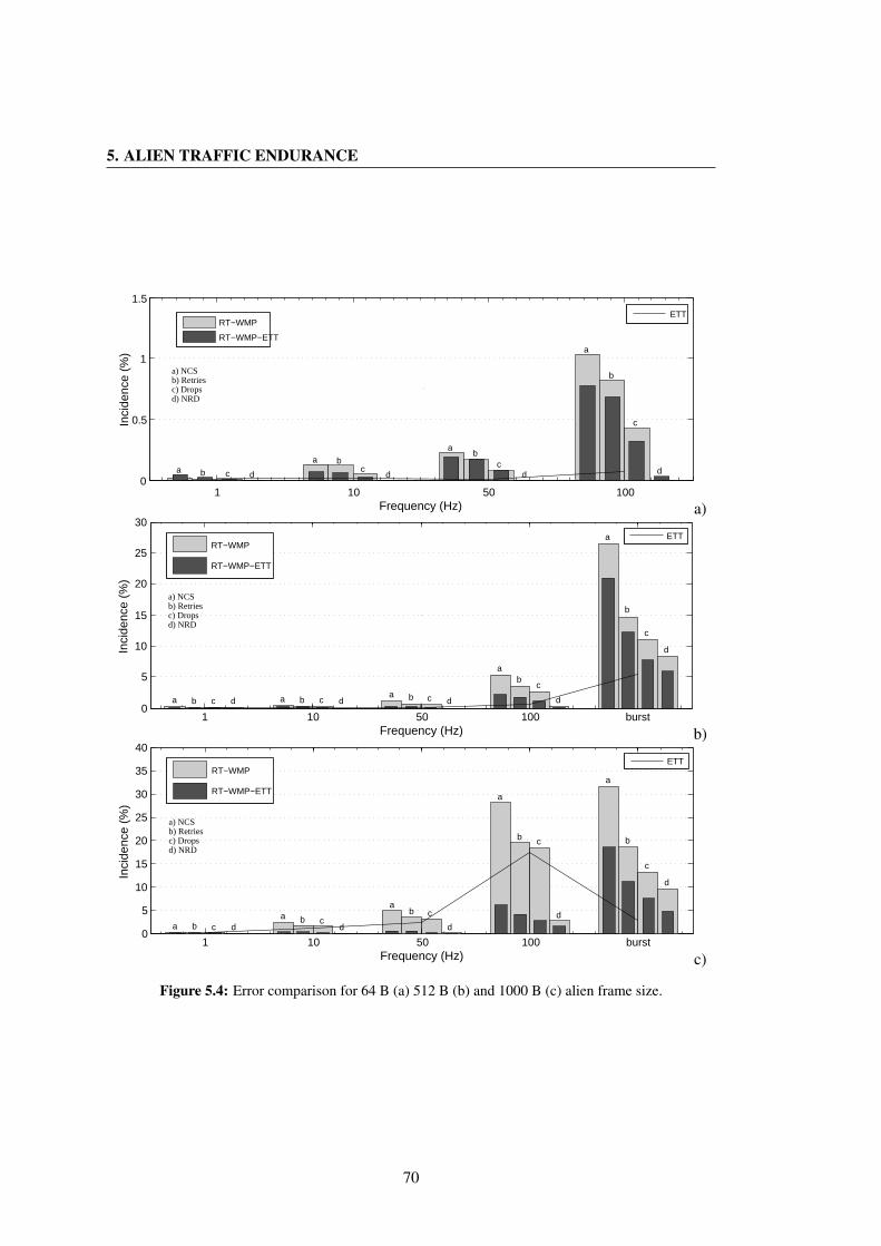
5. ALIEN TRAFFIC ENDURANCE
1 10 50 1000
0.5
1
1.5
a b c d
a bc
d
ab
cd
a
b
c
d
Frequency (Hz)
Inci
denc
e (%
)
RT−WMP
RT−WMP−ETT
ETT
a) NCSb) Retriesc) Dropsd) NRD
a)
1 10 50 100 burst0
5
10
15
20
25
30
a b c d a b c da b c d
ab
c
d
a
b
c
d
Frequency (Hz)
Inci
denc
e (%
)
RT−WMP
RT−WMP−ETT
ETT
a) NCSb) Retriesc) Dropsd) NRD
b)
1 10 50 100 burst0
5
10
15
20
25
30
35
40
a b c da b c
d
ab c
d
a
b c
d
a
b
c
d
Frequency (Hz)
Inci
denc
e (%
)
RT−WMP
RT−WMP−ETT
ETT
a) NCSb) Retriesc) Dropsd) NRD
c)
Figure 5.4: Error comparison for 64 B (a) 512 B (b) and 1000 B (c) alien frame size.
70

5.4 Experimental Results
0 1 10 50 100 burst0
0.5
1
1.5
2
2.5
3x 10
4
a b c a b c a b c a b c ab
c
a
bc
Frequency (Hz)
Del
ay (
us)
(%)
RT−WMP
RT−WMP−ETT
a) 64Bb) 512Bc) 1000B
Figure 5.5: Loop Duration comparison.
50 Hz and 100 Hz) and the ping data size (64 B, 512 B and 1000 B), and burst interferenceby means of a file transfer. The first experiment consisted of analysing the influence of alientraffic on the basic protocol. Figure 5.3 shows the error parameters as functions of the size andperiod of the interference. As can be seen, both frequency and size influence independentlythe amount of errors. However, the upward trend of the graph is, as expected, more markedfor larger alien-data size. Notice that for 1000 byte alien-data size and 100 Hz frequency, forexample, the protocol suffers from about 30% of non consecutive serials while about 3% ofmessages do not reach their destination. This can be a serious problem in a real-time system.The introduction of the timeout extension alleviates the problem. Figure 5.4 shows a compar-ison between some of the error indicators in the basic protocol and the enhanced protocol fordifferent alien frame sizes. As is evident, the enhancement is very effective since it is capa-ble of reducing both the number of errors and retries and the amount of lost messages. Asexpected, the effectiveness of the extension is more marked for larger alien frames. For smallalien frames and low frequencies, in fact, the original and the extended protocol perform quitesimilarly. In some situations the basic RT-WMP even seems to suffer from fewer errors (seefig. 5.4.a), while the higher the frequency and the greater the frames, the greater the improve-ments (see fig. 5.4.b,c). As an example for 1000 byte and 100 Hz alien frames, the proposedsolution reduces the number of errors by about 80% of the original with just 17% of framessuffering from timeout extension. On the other hand, the loop duration suffers from a slightworsening as expected under certain conditions (see fig. 5.5). This is due to the fact that theloops that suffer from a timeout extension in one or more frames will obviously last longerthan the others. Even if this phenomenon can lower the instantaneous bandwidth, this effect isonly partially translated to the global bandwidth thanks to the lower message loss ratio. It ismore evident in situations in which there are many frames affected by ETT (see fig. 5.6). Table5.1 shows the improvements/worsenings brought by the ETT to the basic protocol expressedin percentage terms. The data show very good improvements in terms of errors suffered by theprotocol during normal operation and a negligible worsening in terms of loop duration coupled,however, with an increment in the global bandwidth in certain configurations.
71
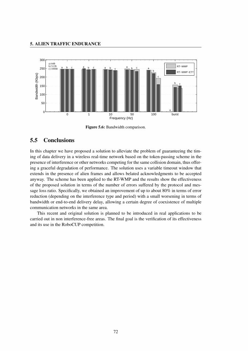
5. ALIEN TRAFFIC ENDURANCE
0 1 10 50 100 burst0
50
100
150
200
250
300
a b c a b c a b ca b c a
b
c
a
b c
Frequency (Hz)
Ban
dwid
th (
Kbp
s)
RT−WMP
RT−WMP−ETT
a) 64Bb) 512Bc) 1000B
Figure 5.6: Bandwidth comparison.
5.5 Conclusions
In this chapter we have proposed a solution to alleviate the problem of guaranteeing the tim-ing of data delivery in a wireless real-time network based on the token-passing scheme in thepresence of interference or other networks competing for the same collision domain, thus offer-ing a graceful degradation of performance. The solution uses a variable timeout window thatextends in the presence of alien frames and allows belated acknowledgments to be acceptedanyway. The scheme has been applied to the RT-WMP and the results show the effectivenessof the proposed solution in terms of the number of errors suffered by the protocol and mes-sage loss ratio. Specifically, we obtained an improvement of up to about 80% in terms of errorreduction (depending on the interference type and period) with a small worsening in terms ofbandwidth or end-to-end delivery delay, allowing a certain degree of coexistence of multiplecommunication networks in the same area.
This recent and original solution is planned to be introduced in real applications to becarried out in non interference-free areas. The final goal is the verification of its effectivenessand its use in the RoboCUP competition.
72

5.5 Conclusions
Size
(B)
6451
210
00Fr
eq(H
z)1
1050
100
110
5010
0bu
rst
110
5010
0bu
rst
ET
T(%
)0.
0095
0.01
0.00
650.
062
0.00
680.
048
0.08
90.
594
5.48
0.04
41.
132.
3717
.529
NC
S(%
)28
653
.683
.774
.933
.754
.924
.241
.179
.222
.28.
99.
4521
.858
.8R
etry
(%)
239
50.8
107.
383
.847
.768
.741
.247
.983
.627
.912
.912
.721
.560
.2D
rops
(%)
191
36.6
107.
874
.839
35.4
22.5
43.7
70.8
12.6
4.46
4.67
14.3
56.4
4N
RD
(%)
n/a
n/a
n/a
n/a
n/a
n/a
n/a
56.2
72.2
n/a
n/a
n/a
52.8
49.5
LD
(%)
97.7
100.
510
0.4
65.5
98.5
103.
199
.497
.511
8.1
99.5
100.
910
1.4
86.9
101.
5
Tabl
e5.
1:R
esul
ts.
73

5. ALIEN TRAFFIC ENDURANCE
74
Chapter 6
Network Connectivity Enforcement
Connectivity is an indispensable requirement for the functioning of a team of cooperatingrobots. Real-time flows exchanged between nodes must not be interrupted if the completionof goals is not to be jeopardized. Network splits must therefore be avoided to guarantee thecorrect operation of the system as a whole and to avoid loss of data or of the robots themselves.
This situation implies collaboration both between individual robots at different levels (com-munication, movement and decision-taking layers) and among the members of the team as awhole to coordinate movements and avoid actions that could split the network and thus jeopar-dize the possibility of completing the goals.
In the literature, however, the issues involved in multi robot applications are usually treatedseparately, in particular the robotic and the communication issues (frequently neglected by therobotics community).
This chapter makes a substantial contribution towards solving this problem and presentsa case study that shows a complete approach, capable of dealing jointly with these issues.This is achieved, specifically, by combining three modules within the system: a CooperativeNavigation Module (CNM), a Communication Module (COM) and a Multi-Task Allocationmodule (MTA).
The CNM module clusters robots in a flexible formation, with one robot being the leaderof the formation and the other robots being the slaves. Each formation is constituted as aMANET derived from the link qualities, causing the system to react in order to prevent networksplits. The connections between robots are maintained by a model based on a spring-dampermechanical analogy.
Connectivity is maintained by means of the RT-WMP protocol used by the COM module.The protocol has been customized and extended for this particular case adding the capabilityof disseminating efficiently a small quantity of broadcast information to the basic scheme.This solution offers a virtual common buffer to the nodes in which they can publish theirown kinematic information and read that of the other nodes with real-time guarantees, withoutjeopardizing the real-time characteristics of the basic scheme and with only a slight worseningin terms of performance. Additionally, RT-WMP provides to the CNM and MTA layers theinformation about link quality among nodes that is used by these upper layers to avoid networksplits and deadlocks, respectively.
75
6. NETWORK CONNECTIVITY ENFORCEMENT
Finally, task allocation techniques have been extended in the MTA module to control therobot clusters, making the accomplishment of tasks compatible with the connectivity con-straints.
Simulations and experimental results in real scenarios are described and discussed. Thesimulations were used to evaluate and select the best of the different techniques developed,which are analyzed by the use of certain proposed metrics. The experiments in real scenariosprovided the opportunity to deal with real problems and assess the reliability of the system.These experiments were designed to highlight the core aspects of the present work, whichare the problems arising in communications with robot mobility and the implications that theconnectivity constraint has on motion planning for successfully completing missions. In thislatter regard, homogeneous robots were used whose goals were to reach specific positions. Therestrictions imposed on task allocation were related only to communications.
This contribution was developed within the framework of the NERO Spanish NationalProject and the URUS European Commission project. The results of this work were publishedin the April 2010 issue of the International Journal of Robotics Research [Tardioli10b].
6.1 Related work
In a multi-robot mission, distributed sensing, control and coordination are essential, and onlypossible if there are communication paths between all the nodes involved (robots and humans);in other words, if the communication network is connected. Usually, robot tasks entail move-ment, and this directly affects the communication network topology and hence the networkconnectivity. The question is how to control the motion of robots to accomplish the missionobjectives while maintaining network connectivity. This fundamental issue has received littleattention in the robotics literature, although it is now an emergent field in many works relatedto robotic missions in real scenarios. A good example is the DARPA Landroids initiative toautonomously cover areas with Wi-Fi [DARPA07].
In [Basu04] movement control algorithms are proposed from the communication fault tol-erance perspective. The idea is to maintain the network biconnected, that is, that there bealways at least two alternate communication paths between each pair of robots. However, theproblem is seen only from the network connectivity point of view, and the fulfillment of mis-sion objectives is not taken into account. In [Facchinetti08] the authors describe an interestingdistributed coordination strategy with the objective maintaining the connectivity among mobilerobots. The proposed approach is based on the periodic broadcast of state information with theend of updating their local view of the network and adapt their trajectory. However, in thisscheme only the leaders are dedicated to the execution of a specific application task while theremaining units are dedicated to maintenance of the connectivity.
In [Rooker04] the Frontier-Based exploration (the objective of the mission) algorithm is ex-tended to deal with network connectivity. These works are limited to simulation and considerthe communication range of robots in relation only to distance. This does not equate with real-ity, where the propagation model is more complicated because the signal depends not only onthe distance, but also on the multiple paths from walls and obstacles. Moreover, communica-tion links usually do not disappear suddenly, and their quality can be measured. In [Nguyen04]
76
6.1 Related work
the signal quality is sensed. In this work, the objective is to maintain communication betweena robot and a base-station. To accomplish this goal, a set of relay robots follows the lead robot.Each node monitors the radio link to the node behind it. When it drops below a preset thresh-old, the node stops and becomes a stationary relay node. Thus, to maintain communicationsa robot chain is deployed. In this work, relay robots only have the mission of maintainingcommunication links. This idea is generalized in [Mosteo09] with a focus on cost bounds forexecution plans. In [Stump08] a similar objective is proposed. A framework is developed tocontrol a team of robots that maintains and improves the communication between a stationaryrobot and another exploring robot. The other members of the team move maintaining a bridgebetween both robots, but only one task at a time is performed by the explorer robot. More-over, no real signals are used and only simulation results are provided. In the present work,however, the system measures real link quality and several tasks can be attempted simultane-ously by the robots, which are always candidates to be relays. Several tasks are planned to besimultaneously accomplished by the robot team.
Cooperating robots need to exchange data on the environment and their own state that isinherently time-constrained [Facchinetti05a]. Unfortunately, protocols for Ad-hoc networkstypically focus on issues such as maximizing throughput or minimizing average message de-lay, neglecting the indeterminism introduced. Moreover, most of the commercial low-level net-work protocols (e.g. 802.11, 802.15.4, etc.) do not provide timeliness guarantees on networktransmissions due to packet collisions, exponential back-offs, and the false blocking problem[Ray03]. Consequently, specific protocols aimed at eliminating indeterminism and supportingreal-time traffic have been developed in recent years, as explained in chapter 2.
The use of the RT-WMP offers support for real-time traffic, priorities and multi-hop capa-bilities, and the necessary information relating to the link quality among the nodes belongingto the network.
As well as the protocol used for communication, a system is needed to ensure that thelink among robots is of sufficient quality. To that end, cooperative robot navigation must beemployed to prevent robots from moving too far apart. There are several proposals for robotformation movement, some of which use a spring model for motion. In [Reif95] restricted po-tential fields were used for simulating spring forces and [Gulec05] used graph theory, where thelinks between nodes are springs. Previous works only had the purpose of maintaining a topol-ogy or formation among the robots, but not maintaining network connectivity as proposed here.To deal with this problem, we have developed a spring-damper model to maintain connectivityamong robots while simultaneously enabling them to perform the mission tasks.
Connectivity constraints add a new complexity to the already NP-hard [Gerkey04] task al-location problem. Basic approaches opportunistically take advantage of network connectivitywhen available [Burgard05], but are not specifically intended to avoid network splits. To dothis, a further possibility is to dictate task generation as well as task allocation. E.g., in ex-ploration, goals may be decided as the result of cost functions that depend on signal quality[Vazquez04, Rooker06]. This is difficult to carry over to more flexible service missions, sincetasks are conditioned by external requirements (e.g. visiting an injured person, and in generalvisiting arbitrary goals), and thus the system cannot create tasks based on its preferences.
More general approaches, in which task generation is not a part of the solution and connec-
77

6. NETWORK CONNECTIVITY ENFORCEMENT
tivity is an explicit requirement, are scarce. In [Wagner04] a behavioral approach can be foundwhere connectivity maintenance is addressed, but is not treated as inviolable. In [Kalra07], aline-of-sight constraint is applied, but the actual link quality is not used.
The allocation method presented in this chapter couples two advantageous aspects of thoseapproaches: reactive allocation based on observed signal conditions, which is considered thecritical constraint, and allocation of given tasks, suitable for a general purpose team not tied toa particular problem. Additionally, as part of our algorithm, we use switchable strategies de-rived from unconstrained approaches such as the Hungarian method [Kuhn55], auction basedheuristics [Mosteo07b] and travelling salesman heuristics [Reinelt94]. In [Mosteo08] the samemulti-robot routing problem under communication constraints is treated, but focusing on alter-native plan building strategies to those evaluated here.
In this work we further develop these techniques extending them to real scenarios, realrobots, and using the actual signal quality as a constraint for the motion and the task alloca-tion techniques. To this end, communication and cooperative motion control components areneeded. This work deals with all these issues within a complete framework: mission accom-plishment, communication connectivity in ad-hoc networks, and robot team cooperative mo-tion. To our knowledge, such an integrated vision of the problem in multi-robot applicationshas not been presented before.
6.2 System Overview
Our motivation is the envisioned prospect of mobile robot teams able to perform tasks in a ver-satile manner while automatically adapting to the communication network conditions, withoutdependence on external infrastructure. This solution is scalable to a relatively small set ofrobots (about 15 units). In this work, our system consists of a set of robots equipped withwireless interfaces. Tasks are modelled as goals to be visited by one of the robots. The missiondefinition is to visit all the goals with any robot in minimum time, while the network remainspermanently connected.
We started from the assumption that maintaining connectivity is a primary constraint neverto be violated. This requirement introduces several other requirements. Firstly, multi-hopsupport is required in the underlying network to extend the coverage area. Secondly, controlover the team movement strategy is needed to prevent robots from moving away and losingconnectivity. Finally, a task allocation system has to be used to dynamically assign tasks torobots.
The approach is based on maintaining multi-hop routes between nodes of sufficient qualityin order to avoid the network becoming disconnected. Thus, a measure of the communicationlink quality is needed. Based on this measure, the robot movements are restricted if necessary.
The approach proposes a modular solution replicated in each robot (see fig. 6.1):
• Cooperative Navigation Module (CNM): generates velocity commands for the robots,based on link qualities and robot goals. This controls the motions to prevent any robotfrom becoming disconnected.
78
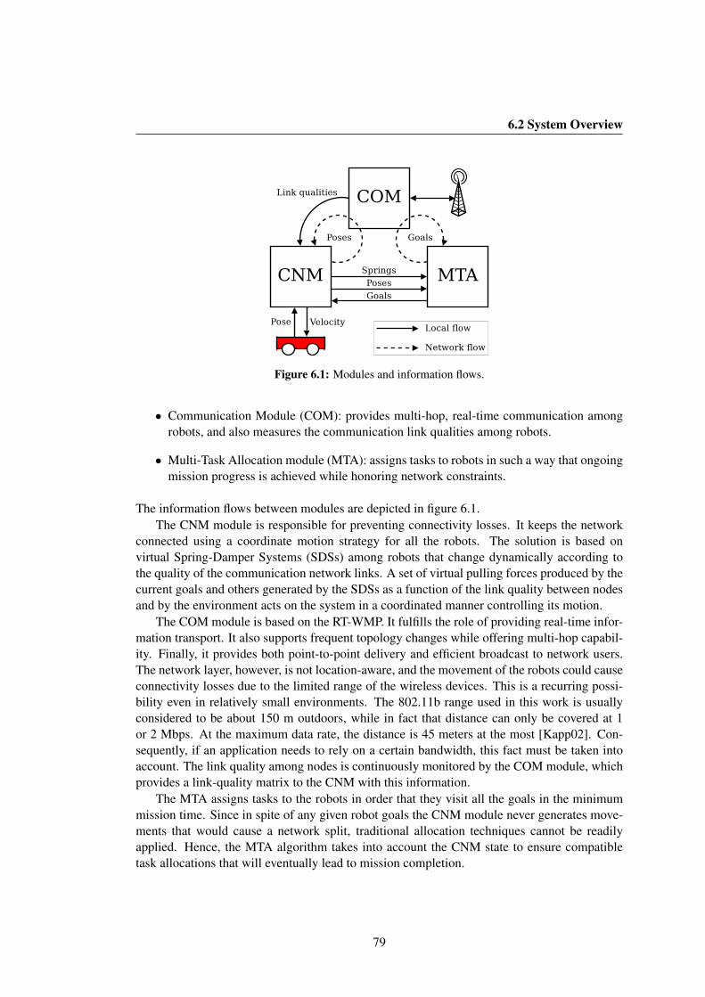
6.2 System Overview
Figure 6.1: Modules and information flows.
• Communication Module (COM): provides multi-hop, real-time communication amongrobots, and also measures the communication link qualities among robots.
• Multi-Task Allocation module (MTA): assigns tasks to robots in such a way that ongoingmission progress is achieved while honoring network constraints.
The information flows between modules are depicted in figure 6.1.The CNM module is responsible for preventing connectivity losses. It keeps the network
connected using a coordinate motion strategy for all the robots. The solution is based onvirtual Spring-Damper Systems (SDSs) among robots that change dynamically according tothe quality of the communication network links. A set of virtual pulling forces produced by thecurrent goals and others generated by the SDSs as a function of the link quality between nodesand by the environment acts on the system in a coordinated manner controlling its motion.
The COM module is based on the RT-WMP. It fulfills the role of providing real-time infor-mation transport. It also supports frequent topology changes while offering multi-hop capabil-ity. Finally, it provides both point-to-point delivery and efficient broadcast to network users.The network layer, however, is not location-aware, and the movement of the robots could causeconnectivity losses due to the limited range of the wireless devices. This is a recurring possi-bility even in relatively small environments. The 802.11b range used in this work is usuallyconsidered to be about 150 m outdoors, while in fact that distance can only be covered at 1or 2 Mbps. At the maximum data rate, the distance is 45 meters at the most [Kapp02]. Con-sequently, if an application needs to rely on a certain bandwidth, this fact must be taken intoaccount. The link quality among nodes is continuously monitored by the COM module, whichprovides a link-quality matrix to the CNM with this information.
The MTA assigns tasks to the robots in order that they visit all the goals in the minimummission time. Since in spite of any given robot goals the CNM module never generates move-ments that would cause a network split, traditional allocation techniques cannot be readilyapplied. Hence, the MTA algorithm takes into account the CNM state to ensure compatibletask allocations that will eventually lead to mission completion.
79

6. NETWORK CONNECTIVITY ENFORCEMENT
Figure 6.2: Spring-damper model to maintain connectivity and motion coordination.
The Communication Module, besides providing the usual networking services, acts as adata source, supplying the CNM with link qualities. The CNM additionally obtains the localrobot pose and propagates it using the communication broadcast service. The Spring-DamperSystems, computed from links and poses are supplied by the navigation module to the Multi-Task Allocation module, which computes goals that are sent back to the CNM and broadcastto other robots. The tight integration of the three modules should be noted. The modulesare identical in all the robots; in this sense the system is decentralized. However, only oneMulti-Task Allocation algorithm is active in providing goals for all the robots using globalinformation, while the rest act as backups. In the case of failure of the robot that executes theallocation algorithm, any other robot would assume its role. The following sections explain thedetails of each module.
6.3 Cooperative Navigation Module
As described in section 6.2, the aim of this layer is to provide a control for the robots to achievetheir objectives while maintaining communication restrictions. We have developed a motionmodel based on a Spring-Damper System analogy (SDS). The forces generated on the SDSstructure are responsible for the coordinate movement of the robots. The model is based onthat presented in [Urcola08], adapted to the communication connectivity problem here dealtwith. Let us briefly present this model.
6.3.1 Spring-Damper model
Figure 6.2 presents a simple structure of the system. This figure illustrates a team of four robotslinked by SDSs. There are two types of robots, mobile and fixed. A fixed robot is, for example,
80

6.3 Cooperative Navigation Module
a base station. We introduced the concept of fixed robot to support applications that needa static base station as, for example, a computer that collects information from all robots orsends commands to them. The objective is to move the robots Ri to a goal using a virtual forceGi whose module is computed as a function of the given leader’s maximum desired velocity,and so it is always bounded. Due to the SDS which attaches two robots, a new force SDi willappear affecting both of them. The forces generated by the SDS for each robot are defined as:
SDi =N∑j=1
sdij aij (6.1)
where A is a matrix whose elements aij represent the links between robots, and the force of aspring-damper link sdij = (sdijx, sdijy) is computed as:
sdij = ks (γ − γ0) du + kv vij (6.2)
where ks and kv are the spring and damping coefficients, chosen to have a slightly overdampedbehavior, du is the unit vector linking i, j robots, and vij is the relative velocity between robotsi and j. These values are calculated from the kinematic information provided by every robot,through the broadcast service of the COM layer (see sec. 6.4). The value of γ is computed asa function of the link quality, s, so it does not represent the actual distance between robots, buta measurement used to establish the connection between each pair of robots when that qualitydecreases. The lower the link quality, the higher γ is. The γ0 represents the rest value of γ.The link quality values are computed by the COM module from a Link Quality Matrix (LQM,explained in section 6.4), describing the topology of the network. A median filter is appliedto obtain s from the LQM values. After several tests we verified that a good function for γ isγ(s) = ks ·(smax−s), smax being the maximum link quality possible between two physically-coupled nodes, and ks a constant computed from the maximum number of robots and the linkquality thresholds explained below.
Since we want to model the behavior of a real system, we have to introduce a damping termDi on the robot forces defined by
Di = fdvi (6.3)
where fd is the damping coefficient and vi = (xi, yi) the velocity vector of the robot. Moreover,the obstacles in the environment could force the robots to modify their relative location. Thisfact is included in the model by means of an external force Ei on the robot Ri, always boundedto a maximum value. Summarizing, the total force Fi on each robot is calculated as:
Fi = Gi + SDi + Di + Ei (6.4)
For this kind of application, this SDS model has several advantages over other approaches tocoordinating the motion of robot teams. It adapts very well to the stated problem for severalreasons. Firstly, this kind of model allows the robot team structure to be maintained consideringthe real kinodynamic constraints of robots, that is, realistic and feasible motions are computed,as we will see in the experiments. Secondly, the link to a task allocator system is direct, because
81

6. NETWORK CONNECTIVITY ENFORCEMENT
Distance
Sign
al
Forbidden Zone
Controlled Zone
Safety Zone
st
Figure 6.3: Theoretical function of the radio signal versus the distance between the transmitter andthe receiver. When the radio has a value less than the safety threshold (st), it enters the Controlledzone where the spring-damper analogy is used to avoid network disconnection.
it can assign tasks (i.e. goals) as attractive forces in a natural manner. Thirdly, influences of theenvironment are also very naturally included in the model as repulsive forces acting on eachrobot, adapting the motion to the dynamism or shape of the environment. Approaches basedon graph models do not incorporate the management of the system dynamics in real situations,making it necessary to deal with dynamic behaviors using other additional models. The pro-posed SDS allows management of cooperative motion, taking into account the real dynamicsof the robots and their connectivity, using a solution that involves a low computational burden.
In order to apply the computed forces calculated by the SDS to each real robot, we use aMotion Generator for differential-drive mobile robots (the kind of robots used in the experi-ments). The Motion Generator transforms these forces (Fi) into linear and angular velocitiesaccording to the equation:
xi = Pxi + QFi (6.5)
By solving this differential equation we can obtain the linear and angular velocities xi = (v , ω),complying with the kinodynamic constraints of the robots. The parameters of P and Q matri-ces are tuned to obtain an overdamped behavior, and to generate feasible trajectories for thereal robots. Details about the model, stability issues, dynamic behavior, parameter tuning andadaptability to the shape and size of the environment can be found in [Urcola08], whose resultsare applicable to the adapted model explained here.
From the point of view of the applied forces, the worst case situation to achieve a missionusing the proposed techniques occurs when all the robots involved in the mission form a chainfrom the base to a goal. This situation will be described in section 6.5. If the goal is unreachablethe spring-damper structures will suffer the maximum forces, the highest being the force of theSDS connecting the base and the first robot. As mentioned above, the parameter ks is computedfor this situation to avoid the link quality between the first robot and the base decreasing undera given threshold.
82

6.3 Cooperative Navigation Module
Figure 6.4: Spring-damper structure generated by the Prim-based algorithm with matrix of linksgenerated for the minimum spanning tree.
6.3.2 Setting up the Virtual Structure
When the link quality between two nodes is high, there is no reason to put an SDS betweenthem. But when the link quality starts to decrease, it is necessary to act to prevent a possiblelink loss. To that end, SDSs are created in our system before the link quality reaches unsafevalues. However, the use of a virtual spring-damper structure to link two nodes restricts themobility of both, and should therefore be used only when really necessary. In fact, SDSs shouldbe created only for those links that have a link quality less than the safety threshold (st) (see fig.6.3) and only when absolutely necessary to maintain the network connectivity. To select theset of necessary SDSs, we have used graph theory. Assimilating the network to a graph, wherethe nodes are the vertices, we fix the weight of the edges as follows: if a link has a qualitygreater than the safety threshold, its weight is zero. Otherwise, the weight is a function of thelink quality. The lower the link quality, the higher the weight of the link. Then, we apply analgorithm based on Prim’s Minimum Spanning Tree (MST) algorithm [Prim57] to such a graphto obtain a spanning tree that contains the maximum possible number of zero-weight edges, andonly the less weighty ones among the other edges. The latter are those corresponding to thelink for which it is necessary to create an SDS. Movement of the robots can imply changesin shared link-quality information and consequently a change in the resulting spanning tree.However, the position of the robots is a continuous function of time (i.e. there are no jumps),and the springs are always created in their rest length. This means that the force generatedat the creation of the SDS is null. This fact guarantees that the system does not suffer fromsudden forces, so that smooth and feasible movements are produced.
This process is completely decentralized. In fact, since all the robots have the same infor-mation about the link qualities in the network, each robot can autonomously calculate the treeand, consequently, the structure of the resulting SDS.
83
6. NETWORK CONNECTIVITY ENFORCEMENT
6.4 Communication Module
As mentioned above, upper layers need information about the link quality among nodes andthe dynamic state of each of the robots. Consequently, the communication module must becapable of providing the link quality between each pair of robots and transporting the kinematicinformation in a multi-hop network with real-time guarantees.
The link quality measurement or prediction is today a challenging question. Some esti-mators have been proposed such as RSSI (Received Signal Strength Indication), SNR (Signalto Noise Ratio), PDR (Packet Delivery Ratio), or BER (Bit Error Rate) [Vlavianos08]. Allof them have limitations while RSSI does not capture the amount of destructive interferenceon links. It is extremely hard to accurately compute the SNR because commercial hardwaredoes not provide noise information while receiving packets, or simply provides no noise levelinformation at all. The use of PDR involves a large latency for estimating the link quality[Souryal06], and the BER computation introduces significant overheads and is sensitive to bitsequences [Vlavianos08]. Moreover, these two latter techniques rely on packet losses that, ingeneral, are not tolerable in real-time systems.
We use RSSI for estimating the link quality because commercial cards provide this measuredirectly (no overheads), and the use of a token passing protocol avoids interferences betweenthe nodes of the network. This latter assumption supposes that no other nodes outside the net-work can interfere with the communication. However, instantaneous RSSI or SNR estimatorscan have temporary peaks due to small scale variations in the multipath propagation. Thusfilters, such as moving average or even Kalman filters (see for example [Farkas08]), must beused to smooth the link quality estimation. For this work we have used RSSI filtered with amoving average. Evidently, any improvement in hardware and estimation techniques can beadopted in the proposed system.
We assume in this work that the robot team is moving in workspaces in which no suddenfalls or changes in signal strength occur. In open and uncluttered environments, such as thoseselected for the experiments, the signal strength changes smoothly, and so the proposed tech-niques are able to enforce connectivity. In cluttered and confined environments (e.g. tunnels)complex propagation patterns occur and serious signal fading can appear. Additional strategiesshould be applied to move the robots in order to recover good signal quality. This is an ongoingwork beyond the scope of this work.
In this work we have used the Real-Time Wireless Multi-hop Protocol because it providesthe real time multi-hop communication needed and a measure of the link qualities. However,any other protocol supporting multi-hop traffic and an estimation of the link qualities can beused in the proposed system. An extension has been made to the protocol to allow the multicastcommunication needed to disseminate kinematic information of the robots to all the nodes ofthe network.
6.4.1 Specializing the RT-WMP
The RT-WMP as initially defined does not have a multicast capability. This means that, toimplement our system, the information on the position of each node (that must reach all theother nodes periodically, see sec. 6.6 for details) would have to travel in the network as unicast
84
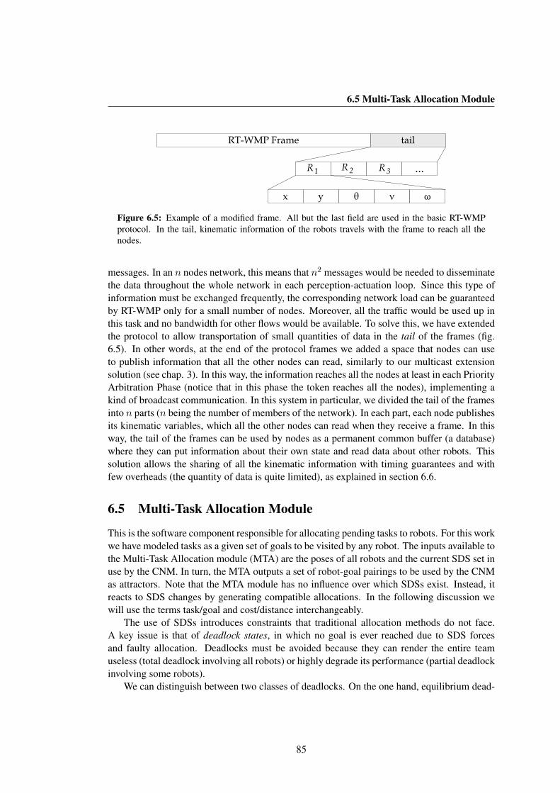
6.5 Multi-Task Allocation Module
x θy ν ω
...
RT-WMP Frame tail
R1 R2 R3
Figure 6.5: Example of a modified frame. All but the last field are used in the basic RT-WMPprotocol. In the tail, kinematic information of the robots travels with the frame to reach all thenodes.
messages. In an n nodes network, this means that n2 messages would be needed to disseminatethe data throughout the whole network in each perception-actuation loop. Since this type ofinformation must be exchanged frequently, the corresponding network load can be guaranteedby RT-WMP only for a small number of nodes. Moreover, all the traffic would be used up inthis task and no bandwidth for other flows would be available. To solve this, we have extendedthe protocol to allow transportation of small quantities of data in the tail of the frames (fig.6.5). In other words, at the end of the protocol frames we added a space that nodes can useto publish information that all the other nodes can read, similarly to our multicast extensionsolution (see chap. 3). In this way, the information reaches all the nodes at least in each PriorityArbitration Phase (notice that in this phase the token reaches all the nodes), implementing akind of broadcast communication. In this system in particular, we divided the tail of the framesinto n parts (n being the number of members of the network). In each part, each node publishesits kinematic variables, which all the other nodes can read when they receive a frame. In thisway, the tail of the frames can be used by nodes as a permanent common buffer (a database)where they can put information about their own state and read data about other robots. Thissolution allows the sharing of all the kinematic information with timing guarantees and withfew overheads (the quantity of data is quite limited), as explained in section 6.6.
6.5 Multi-Task Allocation Module
This is the software component responsible for allocating pending tasks to robots. For this workwe have modeled tasks as a given set of goals to be visited by any robot. The inputs available tothe Multi-Task Allocation module (MTA) are the poses of all robots and the current SDS set inuse by the CNM. In turn, the MTA outputs a set of robot-goal pairings to be used by the CNMas attractors. Note that the MTA module has no influence over which SDSs exist. Instead, itreacts to SDS changes by generating compatible allocations. In the following discussion wewill use the terms task/goal and cost/distance interchangeably.
The use of SDSs introduces constraints that traditional allocation methods do not face.A key issue is that of deadlock states, in which no goal is ever reached due to SDS forcesand faulty allocation. Deadlocks must be avoided because they can render the entire teamuseless (total deadlock involving all robots) or highly degrade its performance (partial deadlockinvolving some robots).
We can distinguish between two classes of deadlocks. On the one hand, equilibrium dead-
85

6. NETWORK CONNECTIVITY ENFORCEMENT
Figure 6.6: Several task allocation related situations: • R1 and R2 are deadlocked by forces inequilibrium. • Let us suppose a faulty allocation policy, with robots abandoning their goal if anSDS is attached to them. R3 could attempt to reach G3, but once its SDS appears, the goal wouldbe abandoned and R3 would move to R′
3 due to the SDS pulling force. At R′3, the SDS is not
needed anymore and disappears, so G3 could be attempted again by R3. This cycle could repeatindefinitely. • Robots linked by SDSs in chain form (R4 and R5) have maximum reachability. •The resulting force of goal assignation and SDSs causes R7 and R8 to move to R′
7 and R′8. At that
point, one of the two is able to move forward using the other as a relay: a chain will have beenformed.
locks happen when a standstill is reached between SDS forces and goal attractors (fig. 6.6, R1
and R2). In this case, no robots are moving and no goal can be reached. On the other hand,dynamic deadlocks (or livelocks) appear when robots are moving, yet fail to complete any task(fig. 6.6, R3).
There are at least two approaches for solving this issue. The on-line approach would try todetect a deadlock once it occurs and adopt measures to escape from it. The off-line approach,which is used in this work, implements an allocation method that is, by design, deadlock-free.
Another point of concern, when there is a static base, is that maximum reachability isachieved with chain configurations (fig. 6.6,R4 andR5). Inducing these configurations ensuresthe completion of tasks that are within team range.
To explain the MTA some concepts must be defined:
• A cluster is each set of robots that are connected, at any hop distance, by SDSs as cur-rently reported by the CNM. Robots without SDSs attached form a trivial mono-robotcluster.
• A supercluster (S-cluster henceforth) is a set of clusters which are aggregated by theMTA algorithm, as we will see. A trivial S-cluster is formed by a single cluster.
86
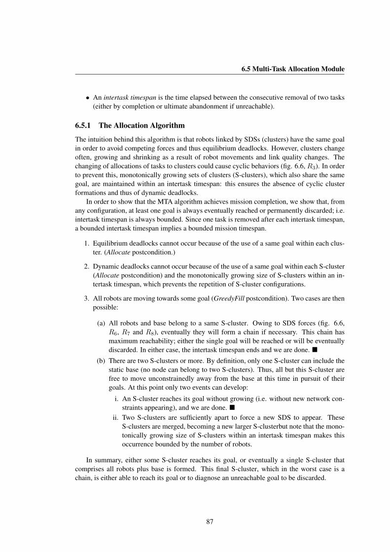
6.5 Multi-Task Allocation Module
• An intertask timespan is the time elapsed between the consecutive removal of two tasks(either by completion or ultimate abandonment if unreachable).
6.5.1 The Allocation Algorithm
The intuition behind this algorithm is that robots linked by SDSs (clusters) have the same goalin order to avoid competing forces and thus equilibrium deadlocks. However, clusters changeoften, growing and shrinking as a result of robot movements and link quality changes. Thechanging of allocations of tasks to clusters could cause cyclic behaviors (fig. 6.6, R3). In orderto prevent this, monotonically growing sets of clusters (S-clusters), which also share the samegoal, are maintained within an intertask timespan: this ensures the absence of cyclic clusterformations and thus of dynamic deadlocks.
In order to show that the MTA algorithm achieves mission completion, we show that, fromany configuration, at least one goal is always eventually reached or permanently discarded; i.e.intertask timespan is always bounded. Since one task is removed after each intertask timespan,a bounded intertask timespan implies a bounded mission timespan.
1. Equilibrium deadlocks cannot occur because of the use of a same goal within each clus-ter. (Allocate postcondition.)
2. Dynamic deadlocks cannot occur because of the use of a same goal within each S-cluster(Allocate postcondition) and the monotonically growing size of S-clusters within an in-tertask timespan, which prevents the repetition of S-cluster configurations.
3. All robots are moving towards some goal (GreedyFill postcondition). Two cases are thenpossible:
(a) All robots and base belong to a same S-cluster. Owing to SDS forces (fig. 6.6,R6, R7 and R8), eventually they will form a chain if necessary. This chain hasmaximum reachability; either the single goal will be reached or will be eventuallydiscarded. In either case, the intertask timespan ends and we are done. �
(b) There are two S-clusters or more. By definition, only one S-cluster can include thestatic base (no node can belong to two S-clusters). Thus, all but this S-cluster arefree to move unconstrainedly away from the base at this time in pursuit of theirgoals. At this point only two events can develop:
i. An S-cluster reaches its goal without growing (i.e. without new network con-straints appearing), and we are done. �
ii. Two S-clusters are sufficiently apart to force a new SDS to appear. TheseS-clusters are merged, becoming a new larger S-clusterbut note that the mono-tonically growing size of S-clusters within an intertask timespan makes thisoccurrence bounded by the number of robots.
In summary, either some S-cluster reaches its goal, or eventually a single S-cluster thatcomprises all robots plus base is formed. This final S-cluster, which in the worst case is achain, is either able to reach its goal or to diagnose an unreachable goal to be discarded.
87

6. NETWORK CONNECTIVITY ENFORCEMENT
6.5.2 Allocation Strategies
Several allocation strategies were tested. For the following descriptions, let SCt be the numberof S-clusters at time instant t, when the subroutine is invoked. See figure 6.13 for a snapshot ofeach strategy execution in the Stage [Gerkey03] simulator. The term gathering in the followingdescriptions refers to the fact that the strategy tries to keep robots together by assigning closetasks.
Hungarian based. The well-known Hungarian method [Kuhn55] computes the optimal pair-ing of tasks/workers. It only assigns one task per worker, leaving any excess tasks aspending for future allocation. We applied it to S-clusters instead of robots to respect theAllocate postcondition.
MINMIX. MINMAX and MINSUM are two common objective functions for multi-robot teams:the former measures the worst robot cost, while the latter measures the sum of all robotcosts. The MINMIX objective [Mosteo07b] showed good properties for general-purposerobotics in some of our previous research, and so we tried it here. It uses a balancedlinear combination of the MINMAX and MINSUM costs to drive the assignation. In thiswork the algorithm was adapted and the insertion heuristic [Reinelt94] is applied usingS-clusters instead of robots.
Greedy with gathering. Let P be the pairing robot-goal of minimum cost, which is allocatedfor starters (hence the greediness). S-cluster mates of the robot in P also receive thatgoal. Then, the previous Hungarian based method (see sec. 6.5.2) is applied to theremaining S-clusters, considering only the SCt − 1 goals closest to the one in P .
TSP with gathering. This algorithm is the only one with a persistent component. While theothers always reallocate remaining tasks from scratch, this one will compute on its firstrun a traveling salesman solution for the one robot with a closest goal. This solution,computed with the insertion heuristic, is kept. Then, and in each subsequent call, thefirst SCt pending goals of this persistent solution are allocated using the Hungarian-based method to the SCt S-clusters. The idea behind this algorithm is to investigate howuseful global planning is in this highly dynamic and reactive system.
6.6 Temporization Issues
To compute the cooperative movement based on the spring-damper analogy, nodes have toshare their kinematic information (absolute pose and velocities) to compute the forces actingon the system using the same set of data. However, due to the distributed nature of the systemand the communication needed to share these data, a perfect synchronization is not possi-ble and thus robots have to work with slightly different information. The time-displacementamong kinematic data on different robots must be sufficiently short to guarantee a correct sys-tem dynamic. The task of propagating the shared data is carried out by the broadcast serviceof the COM module. In fact, in each iteration of the control loop, the latter publishes its kine-matic information (pushing it in the RT-WMP queue) that is propagated by the network. This
88
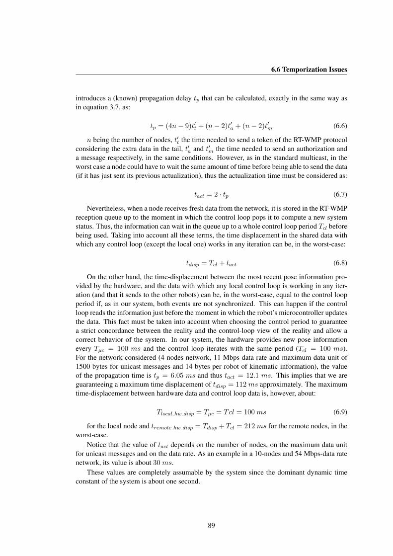
6.6 Temporization Issues
introduces a (known) propagation delay tp that can be calculated, exactly in the same way asin equation 3.7, as:
tp = (4n− 9)t′t + (n− 2)t′a + (n− 2)t′m (6.6)
n being the number of nodes, t′t the time needed to send a token of the RT-WMP protocolconsidering the extra data in the tail, t′a and t′m the time needed to send an authorization anda message respectively, in the same conditions. However, as in the standard multicast, in theworst case a node could have to wait the same amount of time before being able to send the data(if it has just sent its previous actualization), thus the actualization time must be considered as:
tact = 2 · tp (6.7)
Nevertheless, when a node receives fresh data from the network, it is stored in the RT-WMPreception queue up to the moment in which the control loop pops it to compute a new systemstatus. Thus, the information can wait in the queue up to a whole control loop period Tcl beforebeing used. Taking into account all these terms, the time displacement in the shared data withwhich any control loop (except the local one) works in any iteration can be, in the worst-case:
tdisp = Tcl + tact (6.8)
On the other hand, the time-displacement between the most recent pose information pro-vided by the hardware, and the data with which any local control loop is working in any iter-ation (and that it sends to the other robots) can be, in the worst-case, equal to the control loopperiod if, as in our system, both events are not synchronized. This can happen if the controlloop reads the information just before the moment in which the robot’s microcontroller updatesthe data. This fact must be taken into account when choosing the control period to guaranteea strict concordance between the reality and the control-loop view of the reality and allow acorrect behavior of the system. In our system, the hardware provides new pose informationevery Tµc = 100 ms and the control loop iterates with the same period (Tcl = 100 ms).For the network considered (4 nodes network, 11 Mbps data rate and maximum data unit of1500 bytes for unicast messages and 14 bytes per robot of kinematic information), the valueof the propagation time is tp = 6.05 ms and thus tact = 12.1 ms. This implies that we areguaranteeing a maximum time displacement of tdisp = 112ms approximately. The maximumtime-displacement between hardware data and control loop data is, however, about:
Tlocal hw disp = Tµc = Tcl = 100ms (6.9)
for the local node and tremote hw disp = Tdisp + Tcl = 212ms for the remote nodes, in theworst-case.
Notice that the value of tact depends on the number of nodes, on the maximum data unitfor unicast messages and on the data rate. As an example in a 10-nodes and 54 Mbps-data ratenetwork, its value is about 30ms.
These values are completely assumable by the system since the dominant dynamic timeconstant of the system is about one second.
89
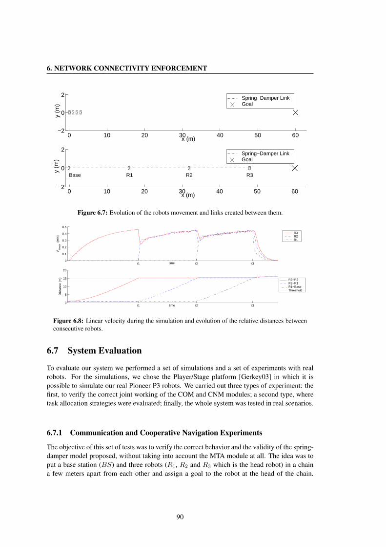
6. NETWORK CONNECTIVITY ENFORCEMENT
0 10 20 30 40 50 60−2
0
2
x (m)
y (
m)
Spring−Damper Link Goal
0 10 20 30 40 50 60−2
0
2
x (m)
y (
m)
R1 R2 R3Base
Spring−Damper Link Goal
Figure 6.7: Evolution of the robots movement and links created between them.
t1 t2 t30
0.1
0.2
0.3
0.4
0.5
time
Vlin
ear (
m/s
)
R3R2R1
t1 t2 t30
5
10
15
20
time
Dis
tanc
e (m
)
R3−R2R2−R1R1−BaseThreshold
Figure 6.8: Linear velocity during the simulation and evolution of the relative distances betweenconsecutive robots.
6.7 System Evaluation
To evaluate our system we performed a set of simulations and a set of experiments with realrobots. For the simulations, we chose the Player/Stage platform [Gerkey03] in which it ispossible to simulate our real Pioneer P3 robots. We carried out three types of experiment: thefirst, to verify the correct joint working of the COM and CNM modules; a second type, wheretask allocation strategies were evaluated; finally, the whole system was tested in real scenarios.
6.7.1 Communication and Cooperative Navigation Experiments
The objective of this set of tests was to verify the correct behavior and the validity of the spring-damper model proposed, without taking into account the MTA module at all. The idea was toput a base station (BS) and three robots (R1, R2 and R3 which is the head robot) in a chaina few meters apart from each other and assign a goal to the robot at the head of the chain.
90
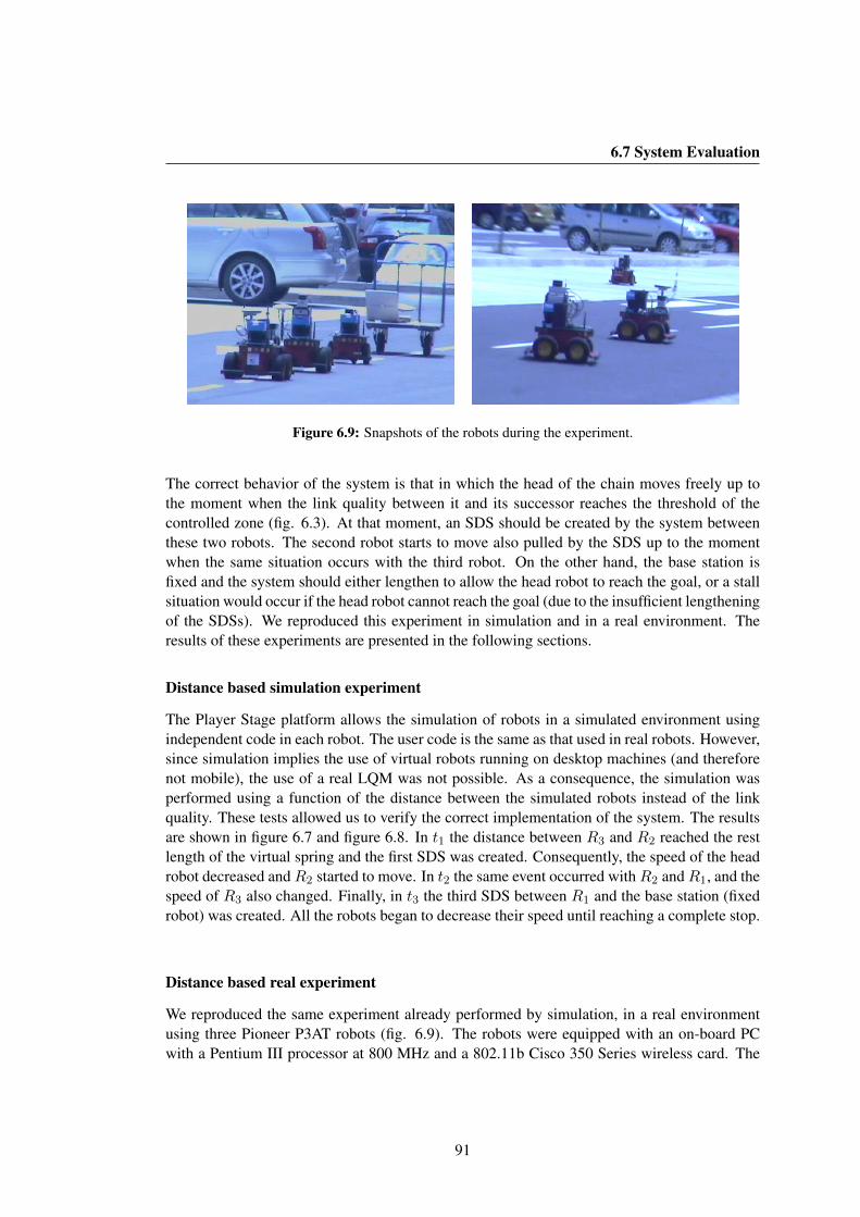
6.7 System Evaluation
Figure 6.9: Snapshots of the robots during the experiment.
The correct behavior of the system is that in which the head of the chain moves freely up tothe moment when the link quality between it and its successor reaches the threshold of thecontrolled zone (fig. 6.3). At that moment, an SDS should be created by the system betweenthese two robots. The second robot starts to move also pulled by the SDS up to the momentwhen the same situation occurs with the third robot. On the other hand, the base station isfixed and the system should either lengthen to allow the head robot to reach the goal, or a stallsituation would occur if the head robot cannot reach the goal (due to the insufficient lengtheningof the SDSs). We reproduced this experiment in simulation and in a real environment. Theresults of these experiments are presented in the following sections.
Distance based simulation experiment
The Player Stage platform allows the simulation of robots in a simulated environment usingindependent code in each robot. The user code is the same as that used in real robots. However,since simulation implies the use of virtual robots running on desktop machines (and thereforenot mobile), the use of a real LQM was not possible. As a consequence, the simulation wasperformed using a function of the distance between the simulated robots instead of the linkquality. These tests allowed us to verify the correct implementation of the system. The resultsare shown in figure 6.7 and figure 6.8. In t1 the distance between R3 and R2 reached the restlength of the virtual spring and the first SDS was created. Consequently, the speed of the headrobot decreased andR2 started to move. In t2 the same event occurred withR2 andR1, and thespeed of R3 also changed. Finally, in t3 the third SDS between R1 and the base station (fixedrobot) was created. All the robots began to decrease their speed until reaching a complete stop.
Distance based real experiment
We reproduced the same experiment already performed by simulation, in a real environmentusing three Pioneer P3AT robots (fig. 6.9). The robots were equipped with an on-board PCwith a Pentium III processor at 800 MHz and a 802.11b Cisco 350 Series wireless card. The
91
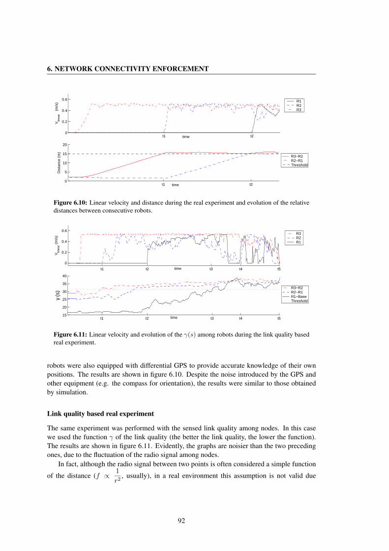
6. NETWORK CONNECTIVITY ENFORCEMENT
t1 t20
0.2
0.4
0.6
time
Vlin
ear
(m/s
) R1R2R3
t1 t20
5
10
15
20
time
Dis
tanc
e (m
)
R3−R2R2−R1Threshold
Figure 6.10: Linear velocity and distance during the real experiment and evolution of the relativedistances between consecutive robots.
t1 t2 t3 t4 t5
0
0.2
0.4
0.6
time
Vlin
ear (
m/s
) R3R2R1
t1 t2 t3 t4 t515
20
25
30
35
40
time
γ (s
)
R3−R2R2−R1R1−BaseThreshold
Figure 6.11: Linear velocity and evolution of the γ(s) among robots during the link quality basedreal experiment.
robots were also equipped with differential GPS to provide accurate knowledge of their ownpositions. The results are shown in figure 6.10. Despite the noise introduced by the GPS andother equipment (e.g. the compass for orientation), the results were similar to those obtainedby simulation.
Link quality based real experiment
The same experiment was performed with the sensed link quality among nodes. In this casewe used the function γ of the link quality (the better the link quality, the lower the function).The results are shown in figure 6.11. Evidently, the graphs are noisier than the two precedingones, due to the fluctuation of the radio signal among nodes.
In fact, although the radio signal between two points is often considered a simple function
of the distance (f ∝ 1
r2, usually), in a real environment this assumption is not valid due
92

6.7 System Evaluation
to interferences, multi-path effect, fading, and so on.Even so, figure 6.11 clearly shows themoments at which the SDS were created by the system. In t1 the value of γ(s) between R3
and R2 increased and passed beyond the threshold causing the first SDS to be created. Therobot R2 started to move. At t2 robot R1 started to move after the link R2 −R1 overcame thethreshold. The delay between this event and t2 was due to a temporary good link between R2
and the base station (not reported in the graph to avoid confusion) that caused the creation ofan alternative multi-hop route and allowed R2 to move a little before the creation of the SDSthat linked it with R1 precisely at t2. This fact shows clearly that in some situations the linkquality among nodes is not directly related to the distance. Between t2 and t3 both links werestable (that is γ(s) were over the threshold for both SDSs) and velocities of R1, R2 and R3
were more or less constant, despite a little oscillation. At t3 γ(s) for the R1-base link (thatgrew rapidly during the movement of the system) reached the threshold and caused the thirdSDS to be created and the stopping of R1. At the same time, links R2 − R3 and R2 − R1
reached a similar γ value and thus a null result force. This fact caused the slowdown of R2
until a complete stop at around t4 that in turn caused a slowdown of R3. After that, fluctuationof the radio signal among robots caused further movements until a complete stop occurred att5 due to force equilibrium. A temporary signal quality improvement between R1 and baseprovoked an R1 advancement, allowing R3 to reach the goal at t5. As can be deduced fromthe experiment, using the link quality instead of distance provides a different behavior, so theuse of distance to create robot connections does not work. Another conclusion is that the SDSmodel is well adapted to controlling the dynamic system motion in real situations providing, inthis respect, similar results to those obtained by simulation.
Effect of obstacles on the link quality
To verify the effect caused by the presence of obstacles and the absence of line-of-sight on oursystem, we performed an experiment in an indoor environment, shown in figure 6.12. We usedtwo mobile robots and a fixed base station, and recorded the link quality among robots and basestation. The goal of the experiment was to move the robot R2 away from R1 in a corridor andobserve the behavior of the link quality and the behavior of the robots when the mobile robotturned around a corner and entered a room (see fig. 6.12). As can be seen in figure 6.12.e, thefunction of the link quality (γ(s)) between R1 and R2 remained more or less constant up to themoment in which R2 started to turn to enter the room (t1). At this moment, in fact, the line ofsight between the antennas of R2 and R1 was partially cut off by the laser head of the former.The function γ grew and an SDS was created between both robots at time t2 (fig. 6.12.b).At this moment R1 started to move to reestablish a good link quality with the leader robot.Despite the movement, γ(s) between R2 and R1 continued growing because R2 entered theroom (t3). Nevertheless, the γ(s) between R1 and the base station grew very slowly (there stillbeing line of sight between them) up to the moment (t4) at which the threshold was reachedand a second SDS was created by the system (fig. 6.12.c). After that both robots started to slowdown because the pulling forces imposed by the SDS and the respective γ functions oscillated alittle around the equilibrium point. At this moment the robots could not move forward withoutloss of communication with the base station.
93
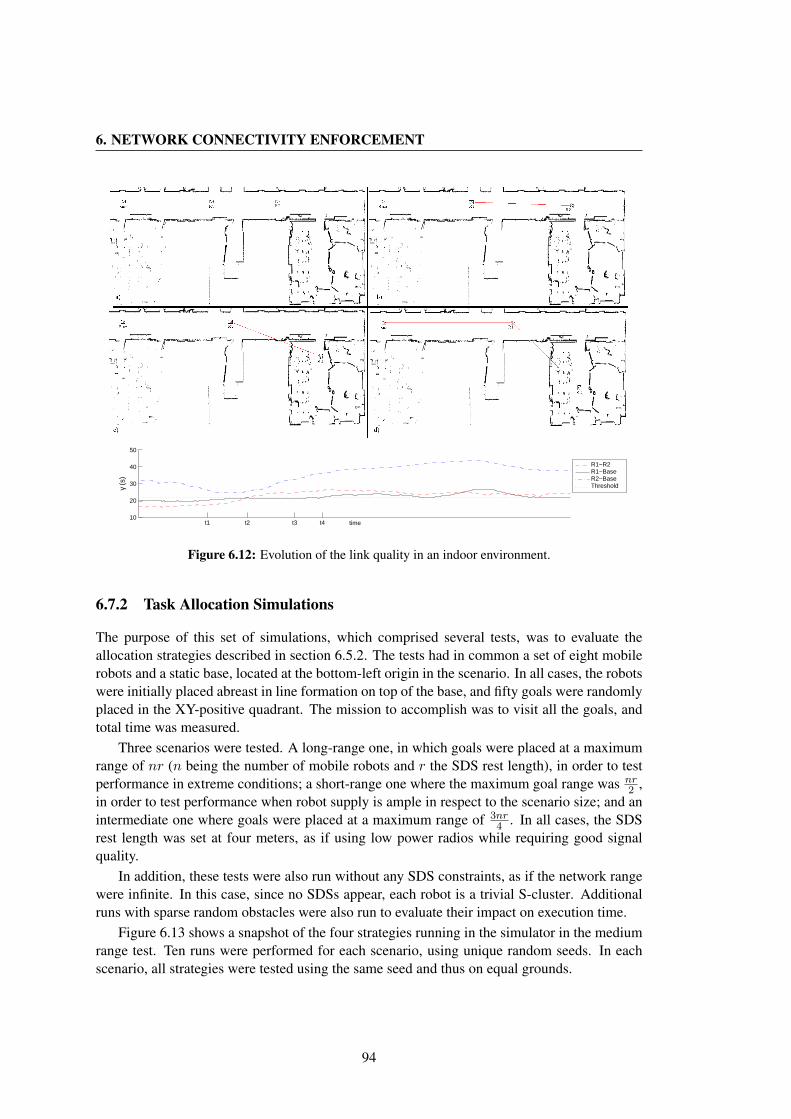
6. NETWORK CONNECTIVITY ENFORCEMENT
t1 t2 t3 t410
20
30
40
50
time
γ (s
)
R1−R2R1−BaseR2−BaseThreshold
Figure 6.12: Evolution of the link quality in an indoor environment.
6.7.2 Task Allocation Simulations
The purpose of this set of simulations, which comprised several tests, was to evaluate theallocation strategies described in section 6.5.2. The tests had in common a set of eight mobilerobots and a static base, located at the bottom-left origin in the scenario. In all cases, the robotswere initially placed abreast in line formation on top of the base, and fifty goals were randomlyplaced in the XY-positive quadrant. The mission to accomplish was to visit all the goals, andtotal time was measured.
Three scenarios were tested. A long-range one, in which goals were placed at a maximumrange of nr (n being the number of mobile robots and r the SDS rest length), in order to testperformance in extreme conditions; a short-range one where the maximum goal range was nr
2 ,in order to test performance when robot supply is ample in respect to the scenario size; and anintermediate one where goals were placed at a maximum range of 3nr
4 . In all cases, the SDSrest length was set at four meters, as if using low power radios while requiring good signalquality.
In addition, these tests were also run without any SDS constraints, as if the network rangewere infinite. In this case, since no SDSs appear, each robot is a trivial S-cluster. Additionalruns with sparse random obstacles were also run to evaluate their impact on execution time.
Figure 6.13 shows a snapshot of the four strategies running in the simulator in the mediumrange test. Ten runs were performed for each scenario, using unique random seeds. In eachscenario, all strategies were tested using the same seed and thus on equal grounds.
94

6.7 System Evaluation
a) Hungarian method. b) MINMIX.
P
c) Greedy with gathering. d) TSP with gathering.
Figure 6.13: Snapshots of simulation runs for the allocation strategies. Solid lines linking robotsindicate S-clusters, while dashed lines from robots to goals indicate assignations. Absent X insome snapshots are already visited goals. Hollow squares are obstacles. In a) it can be seen thatrobots do not attempt to remain close to one another, and only one task per robot is allocated. In b)can be seen the complete MINMIX plans for each S-cluster. In c) can be seen the greedy pairingP and how all the remaining allocated tasks are the closest ones to the task in P . In d) can be seenthe global TSP solution and how the first tasks in it are assigned to S-clusters.
Figure 6.14.a summarizes the time results. In the short-range test we observed a small timepenalty due to network constraints when compared to unconstrained runs. However, the strate-gies followed the same trends in all cases, the non-gathering ones –Hungarian and MINMIX–being the best performers in both constrained and unconstrained runs. This is understandable,since in the short-range scenario there is less area to cover, and thus fewer SDS occurrences.Hence, strategies without gathering do not artificially constrain robot spreading.
The time penalty was greater in the middle-range test. It affected the non-gathering strate-gies in particular, in a trend that was even more pronounced in the long-range test. We saw that
95
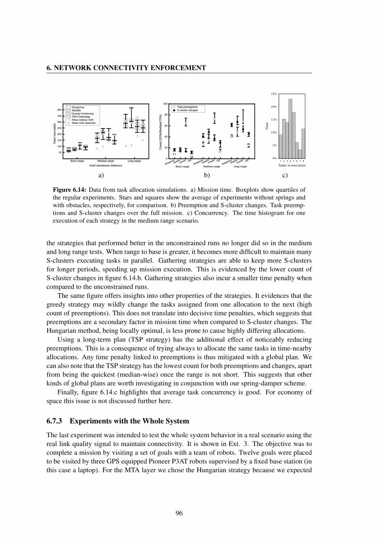
6. NETWORK CONNECTIVITY ENFORCEMENT
1 2 3 4 5 6 7 8
Tasks in execution
0%
5%
10%
15%
20%
25%
Tim
e
a) b) c)
Figure 6.14: Data from task allocation simulations. a) Mission time. Boxplots show quartiles ofthe regular experiments. Stars and squares show the average of experiments without springs andwith obstacles, respectively, for comparison. b) Preemption and S-cluster changes. Task preemp-tions and S-cluster changes over the full mission. c) Concurrency. The time histogram for oneexecution of each strategy in the medium range scenario.
the strategies that performed better in the unconstrained runs no longer did so in the mediumand long range tests. When range to base is greater, it becomes more difficult to maintain manyS-clusters executing tasks in parallel. Gathering strategies are able to keep more S-clustersfor longer periods, speeding up mission execution. This is evidenced by the lower count ofS-cluster changes in figure 6.14.b. Gathering strategies also incur a smaller time penalty whencompared to the unconstrained runs.
The same figure offers insights into other properties of the strategies. It evidences that thegreedy strategy may wildly change the tasks assigned from one allocation to the next (highcount of preemptions). This does not translate into decisive time penalties, which suggests thatpreemptions are a secondary factor in mission time when compared to S-cluster changes. TheHungarian method, being locally optimal, is less prone to cause highly differing allocations.
Using a long-term plan (TSP strategy) has the additional effect of noticeably reducingpreemptions. This is a consequence of trying always to allocate the same tasks in time-nearbyallocations. Any time penalty linked to preemptions is thus mitigated with a global plan. Wecan also note that the TSP strategy has the lowest count for both preemptions and changes, apartfrom being the quickest (median-wise) once the range is not short. This suggests that otherkinds of global plans are worth investigating in conjunction with our spring-damper scheme.
Finally, figure 6.14.c highlights that average task concurrency is good. For economy ofspace this issue is not discussed further here.
6.7.3 Experiments with the Whole System
The last experiment was intended to test the whole system behavior in a real scenario using thereal link quality signal to maintain connectivity. It is shown in Ext. 3. The objective was tocomplete a mission by visiting a set of goals with a team of robots. Twelve goals were placedto be visited by three GPS equipped Pioneer P3AT robots supervised by a fixed base station (inthis case a laptop). For the MTA layer we chose the Hungarian strategy because we expected
96
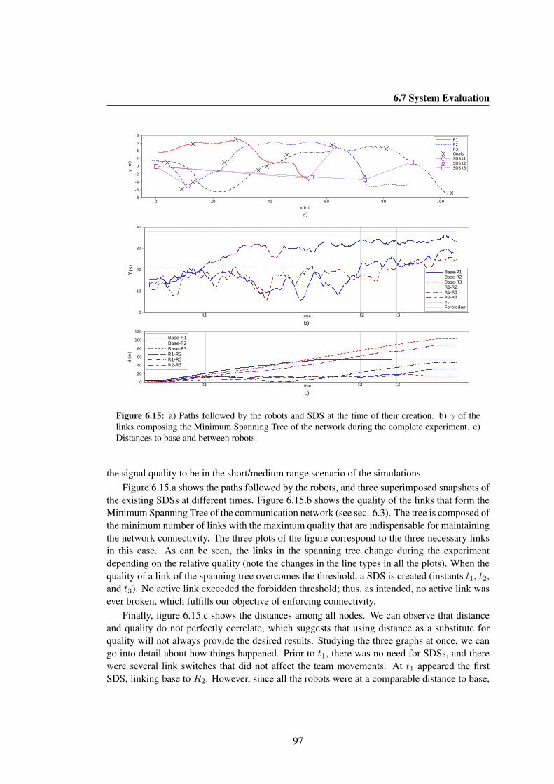
6.7 System Evaluation
0 20 40 60 80 100
a)x (m)
-8
-6
-4
-2
0
2
4
6
8
y (
m)
R1R2R3GoalsSDS t1SDS t2SDS t3
t1 t2 t3
b)time
0
10
20
30
40
ϒ(s)
Base-R1Base-R2Base-R3R1-R2R1-R3R2-R3ϒₒForbidden
t1 t2 t3
c)time
0
20
40
60
80
100
120
d (
m)
Base-R1Base-R2Base-R3R1-R2R1-R3R2-R3
Figure 6.15: a) Paths followed by the robots and SDS at the time of their creation. b) γ of thelinks composing the Minimum Spanning Tree of the network during the complete experiment. c)Distances to base and between robots.
the signal quality to be in the short/medium range scenario of the simulations.Figure 6.15.a shows the paths followed by the robots, and three superimposed snapshots of
the existing SDSs at different times. Figure 6.15.b shows the quality of the links that form theMinimum Spanning Tree of the communication network (see sec. 6.3). The tree is composed ofthe minimum number of links with the maximum quality that are indispensable for maintainingthe network connectivity. The three plots of the figure correspond to the three necessary linksin this case. As can be seen, the links in the spanning tree change during the experimentdepending on the relative quality (note the changes in the line types in all the plots). When thequality of a link of the spanning tree overcomes the threshold, a SDS is created (instants t1, t2,and t3). No active link exceeded the forbidden threshold; thus, as intended, no active link wasever broken, which fulfills our objective of enforcing connectivity.
Finally, figure 6.15.c shows the distances among all nodes. We can observe that distanceand quality do not perfectly correlate, which suggests that using distance as a substitute forquality will not always provide the desired results. Studying the three graphs at once, we cango into detail about how things happened. Prior to t1, there was no need for SDSs, and therewere several link switches that did not affect the team movements. At t1 appeared the firstSDS, linking base to R2. However, since all the robots were at a comparable distance to base,
97

6. NETWORK CONNECTIVITY ENFORCEMENT
link quality changes prevented any strong preference for one of them as a relay, and thus wecan observe that the base used, for short periods of time, any of the three robots as a relay forthe other two. Eventually, R1 lagged behind and consolidated as the stable relay between baseand R2, R3. When these robots moved away from R1, eventually a new relay was necessary:at t2, R2 was linked with a SDS to R1.
Finally, at t3 a third SDS appeared when R3 took the lead towards the farther goal. We canobserve that, with the parameters used, SDSs were quite short when created (circa 10 m) butthe robots still retained a good level of mobility as the SDS elongated. It was not until shortlybefore t2, as link quality decreased, that R1 was stopped by the SDS force pulling from base.Also, R2 did not stop moving (fig. 6.15.c) until the very end of the mission, which reveals thatits SDS to R1 was not yet at equilibrium. This shows that using distance as the SDS triggerwould be difficult: either we could err by being too conservative, or we could try to allowmore mobility and lose connectivity due to signal oscillations. Since different environmentconditions could greatly change the expected maximum length of a link, this again confirmsthat using link quality is a better approach. Task allocation worked as expected given the SDSsat each instant achieveing the mission completion with a low time penalty while obtaining agood communication quality at all times.
6.8 Conclusions
In this chapter we have presented a complete system that enforces communication connectiv-ity in multi-robot missions, such as rescue or surveillance. Our approach proposes a modularsolution: a Communication Module, a Cooperative Navigation Module and a Multi-Task Allo-cation module.
The Communication Module, based on the RT-WMP, offers to upper layers real-time multi-hop communication and information about link quality among the members of the team. More-over, it provides an additional broadcast capability that allows the dissemination of kinematicinformation. This feature, developed specifically for this application, permits the sharing of asmall quantity of data among nodes with few overheads using a scheme similar to the PME.
The Cooperative Navigation Module deals with the coordinated movement of the robots us-ing a physical analogy to a Spring-Damper System; this prevents disconnection of the networkthrough the monitoring of the link quality among nodes. The Multi-Task Allocation moduleguarantees, within the current restrictions imposed on the problem, the completion of the teamtasks while aiming for minimization of mission time. Tasks are reactively reallocated to adaptto the changing communication network topology, taking advantage of the clusters naturallyformed by the dynamics of the cooperative navigation module. Several high-level allocationstrategies were tested, demonstrating that for medium and long-range missions a global planand keeping robots together are advantageous. This minimizes changes in network topologyand task preemption, thus allowing better task parallelization. The whole system has beenimplemented and tested by means of simulations and real multi-robot experiments.
The results show that the proposed solution fulfills the objective of maintaining networkconnectivity at all times while completing the assigned tasks. From the experiments we verifiedthat the use of the link quality information, together with a virtual Spring-Damper System, is
98

6.8 Conclusions
a valid solution for maintaining network connectivity even in the presence of obstacles andabsence of line-of-sight. Estimation of link quality is an open field of research, and any newresult in this field will improve the behavior of this system. The navigation and allocationtechniques are being extended to allow for more complex obstacles than those considered sofar.
To conclude, we have developed a solution that integrates communications, motion coordi-nation and task allocation, which are usually treated in isolation. In addition, we have describednovel techniques for each of the three integrated subsystems.
99

6. NETWORK CONNECTIVITY ENFORCEMENT
100
Chapter 7
RT-WMP in Confined Environments
Providing communications capability both for exploitation and emergency situations in hos-tile underground environments such as tunnels or mines has been an important issue in recentdecades. As a result, tunnels and mines have attracted the interest of researchers who have pro-posed several studies about EM wave propagation, channel characterization and measurements[Lienard00, Dudley07].
As is well known, the most widely used underground communication system is the LeakyFeeder (LF). However, LF based networks are very costly to deploy, maintain and, in addition,lack standardization. Moreover, in an emergency scenario (a collapse or similar) an LF basedcommunication system could be damaged and rendered useless.
In this chapter we propose the use of RT-WMP jointly with its QoS extension to providethe necessary support for the exchange of time-sensitive data in such environments betweenmobile nodes, taking advantage of its native mobility and multi-hop support to implement atype of MESH network. To do this, we have designed and implemented a complete low-costhardware/software platform constituted by a set of embedded-PC-based nodes to be deployedin the confined area at strategic points in order to have a flexible infrastructure capable ofoffering a multimedia link to mobile nodes.
We tested this proposal in a real application in the Somport tunnel, the 8 km-long railroadlinking Canfranc, Spain with France. The specific topology and location led us to produce anadaptation or, more concretely, a specialization of RT-WMP to perform better in this type ofenvironment, taking advantage of the a priori knowledge of the topology.
This contribution is a proof of concept solution and has been developed within the frame-work of the NERO Spanish National Project. The results of this work have to be presented atthe third International Conference on Wireless Communications in Underground and ConfinedAreas held in Val-d’Or, Canada, from August 23 to 24, 2010 [Sicignano10b] that, however, hasbeen postponed.
7.1 Related Work
The 802.11 networks have been extensively tested in outdoor and indoor areas but very fewperformance measurements have been carried out in confined environments such as tunnels or
101
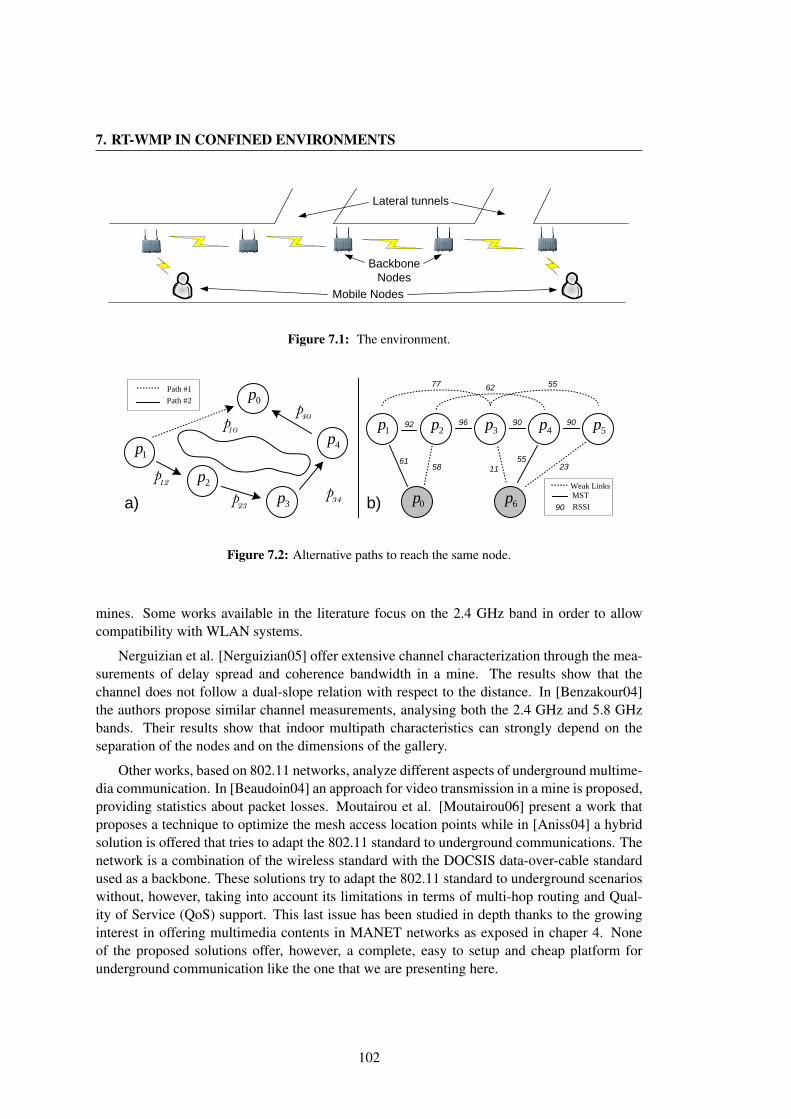
7. RT-WMP IN CONFINED ENVIRONMENTS
Lateral tunnels
BackboneNodes
Mobile Nodes
Figure 7.1: The environment.
5p1p 3p 4p2p
0p 6p
92 96 90 90
77 62 55
231155
5861
Weak LinksMST
90 RSSI
0p
1p
3p
4p
2p
p10p40
p12p34p23
Path #1Path #2
a) b)
Figure 7.2: Alternative paths to reach the same node.
mines. Some works available in the literature focus on the 2.4 GHz band in order to allowcompatibility with WLAN systems.
Nerguizian et al. [Nerguizian05] offer extensive channel characterization through the mea-surements of delay spread and coherence bandwidth in a mine. The results show that thechannel does not follow a dual-slope relation with respect to the distance. In [Benzakour04]the authors propose similar channel measurements, analysing both the 2.4 GHz and 5.8 GHzbands. Their results show that indoor multipath characteristics can strongly depend on theseparation of the nodes and on the dimensions of the gallery.
Other works, based on 802.11 networks, analyze different aspects of underground multime-dia communication. In [Beaudoin04] an approach for video transmission in a mine is proposed,providing statistics about packet losses. Moutairou et al. [Moutairou06] present a work thatproposes a technique to optimize the mesh access location points while in [Aniss04] a hybridsolution is offered that tries to adapt the 802.11 standard to underground communications. Thenetwork is a combination of the wireless standard with the DOCSIS data-over-cable standardused as a backbone. These solutions try to adapt the 802.11 standard to underground scenarioswithout, however, taking into account its limitations in terms of multi-hop routing and Qual-ity of Service (QoS) support. This last issue has been studied in depth thanks to the growinginterest in offering multimedia contents in MANET networks as exposed in chaper 4. Noneof the proposed solutions offer, however, a complete, easy to setup and cheap platform forunderground communication like the one that we are presenting here.
102
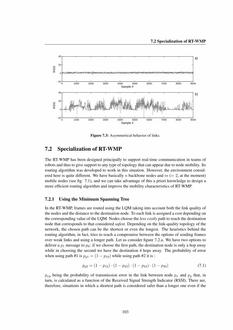
7.2 Specialization of RT-WMP
0 1000 2000 3000 4000 5000 6000 7000 8000 9000−20
0
20
40
Sample #
RS
SI
0 1000 2000 3000 4000 5000 6000 7000 8000 9000−20
0
20
40
Sample #
RS
SI
b)
a)
Figure 7.3: Asymmetrical behavior of links.
7.2 Specialization of RT-WMP
The RT-WMP has been designed principally to support real-time communication in teams ofrobots and thus to give support to any type of topology that can appear due to node mobility. Itsrouting algorithm was developed to work in this situation. However, the environment consid-ered here is quite different. We have basically n backbone nodes and m (= 2, at the moment)mobile nodes (see fig. 7.1), and we can take advantage of this a priori knowledge to design amore efficient routing algorithm and improve the mobility characteristics of RT-WMP.
7.2.1 Using the Minimum Spanning Tree
In the RT-WMP, frames are routed using the LQM taking into account both the link quality ofthe nodes and the distance to the destination node. To each link is assigned a cost depending onthe corresponding value of the LQM. Nodes choose the less costly path to reach the destinationnode that corresponds to that considered safest. Depending on the link-quality topology of thenetwork, the chosen path can be the shortest or even the longest. The heuristics behind therouting algorithm, in fact, tries to reach a compromise between the options of sending framesover weak links and using a longer path. Let us consider figure 7.2.a. We have two options todeliver a p1 message to p0: if we choose the first path, the destination node is only a hop awaywhile in choosing the second we have the destination 4 hops away. The probability of errorwhen using path #1 is pp1 = (1− p10) while using path #2 it is :
pp2 = (1− p12) · (1− p23) · (1− p34) · (1− p40) (7.1)
pxy being the probability of transmission error in the link between node px and py that, inturn, is calculated as a function of the Received Signal Strength Indicator (RSSI). There are,therefore, situations in which a shortest path is considered safer than a longer one even if the
103

7. RT-WMP IN CONFINED ENVIRONMENTS
a) b)
Good Link
QoS FlowWeak Link
p0 p6 p6p0 p6 p6
Figure 7.4: An illustration of mobility scheme.
links are all stronger in the latter.This behavior is desirable in generic networks (e.g. a team of robots uniformly distributed).
However, in situations in which (part of) the topology is known, the routing algorithm canbe improved to obtain an even safer behavior. In tunnels, for example, the backbone nodesare placed at strategic points to guarantee a good and, above all, symmetric link among them.Moreover, they may have high-gain antenna and the transmission power is substantially greaterthan that of the mobile nodes. This implies that the probability of communication error betweenadjacent nodes is very low, almost negligible. Figure 7.3 shows, just to give an example,the difference between the RSSI registered during the experiment described in section 7.3.2between two backbone nodes (fig. 7.3.a) and between one mobile node and one backbone node(fig. 7.3.b). As is evident, the backbone link can be considered practically symmetric whilethe other presents a high variability that can jeopardize the correct operation of the routingalgorithm.
We decided, therefore, to force the protocol to use backbone nodes for backbone commu-nication and mobile nodes to link themselves to the closest (in terms of link quality) backbonenode. To do this, we reduced the topology of the network to a spanning tree where only the bestlinks are selected or, more concretely, to a Minimum Spanning Tree (MST), applying Prim’salgorithm to the LQM. Figure 7.2.b shows the results of this process. The backbone topologyof the network becomes a string and the nodes communicate using the best possible link withthe backbone. The rationale is that the nodes see the network as a tree whose branches are thebest possible links. The general view that nodes have of the topology is just the existence ofa backbone and some mobile nodes. An example of how this new scheme works is given infigure 7.4. As we can see in figure 7.4.a, the link quality between nodes p0 and p1 enables astable connection between the mobile nodes (p0 and p1) and the backbone node while the weaklink is ruled out by Prim’s algorithm. While p1 is moving along the tunnel (Figure 7.4.b), theprotocol manages the link quality change allowing multi-hop re-routing across the network andguaranteeing a connection all the time.
7.3 Evaluation
The main experiment was performed in the Somport tunnel linking the old railway from Can-franc (Spain) to Pau (France) situated in the Pyrenees. The tunnel (see fig. 7.5) has a maximumheight of 6 m, 4.7 m width, 7.7 km length and has a change in slope. It has several lateral gal-leries (about 400 m apart) along its extension and the walls have a roughness in the order ofabout 2 cm. The tunnel is closed to traffic, so we can assume the experiments were made in
104

7.3 Evaluation
Figure 7.5: An illustration of the Somport tunnel.
0 500 1000 1500 2000 2500 3000−80
−60
−40
RS
SI [
dBm
]
0 500 1000 1500 2000 2500 300020
30
40
distance [m]
Del
ay S
prea
d [n
s]
Figure 7.6: RSSI and Delay Spread values sensed from receiver.
stationary conditions. Tests have been done along a stretch of about 7.5 km.Five nodes equipped with minimal embedded and dedicated hardware (100x160 mm PcEngines
ALIX3D3 board, battery powered) and Atheros chipset-based wireless cards and running theMaRTE OS [Rivas01] implementation of RT-WMP, were distributed along the tunnel and usedas backbone nodes. In addition, two laptop computers running Linux OS were used as mobilenodes. The voice was sampled at 8 Khz and 16 bit per sample and was compressed using thespeex [SPEEX09] codec to obtain a full-duplex communication of 15 Kbps bandwidth for eachflow. Each RT-WMP-QoS message contained four speex voice packets. The deadline of thepackets was fixed at 150ms following the ITU-T recommendations [ITU03].
7.3.1 Preliminary Tests
Before performing the final test, however, we made a set of additional experiments to inves-tigate the environment in which the experiment was to take place and chose the appropriateparameters to obtain satisfactory results.
The first test was measuring the RSSI and Delay Spread along the tunnel to obtain infor-mation about the best places to put the backbone nodes, avoiding zones affected by fading orinterference. The second set of tests were performed to discover the best parameters to obtain acorrect and effective voice communication in terms of packet aggregation (the number of voice
105
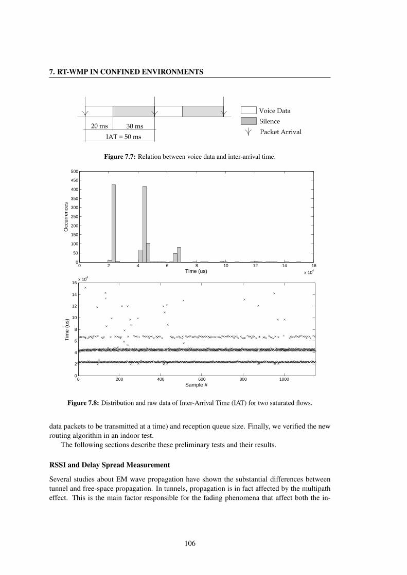
7. RT-WMP IN CONFINED ENVIRONMENTS
20 msIAT = 50 ms
30 ms
Voice DataSilencePacket Arrival
Figure 7.7: Relation between voice data and inter-arrival time.
0 2 4 6 8 10 12 14 16
x 104
0
50
100
150
200
250
300
350
400
450
500
Time (us)
Occ
urre
nces
0 200 400 600 800 10000
2
4
6
8
10
12
14
16x 10
4
Sample #
Tim
e (u
s)
Figure 7.8: Distribution and raw data of Inter-Arrival Time (IAT) for two saturated flows.
data packets to be transmitted at a time) and reception queue size. Finally, we verified the newrouting algorithm in an indoor test.
The following sections describe these preliminary tests and their results.
RSSI and Delay Spread Measurement
Several studies about EM wave propagation have shown the substantial differences betweentunnel and free-space propagation. In tunnels, propagation is in fact affected by the multipatheffect. This is the main factor responsible for the fading phenomena that affect both the in-
106

7.3 Evaluation
0 2 4 6 8 10 12 14 16 18
x 104
0
200
400
600
800
1000
1200
Time (us)
Occ
urre
nces
0 1000 2000 3000 4000 5000 6000 70000
0.5
1
1.5
2
2.5x 10
5
Tim
e (u
s)
Position (m)
Figure 7.9: Distribution and raw data of Inter-Arrival Time (IAT).
tensity and the quality of the signal that reaches a receiver. The first experiment was designedto evaluate the variation of the power sensed by the receiver in order to know the radio signaland its variability along the tunnel and the effect of the fading on the measurements. Thuswe used a procedure to measure the RSSI received by a mobile node while a fixed source wastransmitting. At the same time, we measured the Delay Spread using a spectrum analyzer. Themeasurement was repeated every 25 meters over 3.2 km and the results are shown in figure 7.6.
As we can see, it is possible to appreciate some typical tunnel propagation effects, charac-terized by the fading effect due to the fact that we are operating above the cut-off frequency.
As expected, the mean radio-signal decreases with distance but the fading has a strongpresence both in terms of RSSI and Delay Spread. The RSSI and Delay Spread variation areinfluenced also by the presence of lateral galleries that affect the received signal, producing asharp fall in the signal intensity in correspondence to the lateral galleries. On the other hand,the wave guide effect allows higher RSSI values along the tunnel than in open space. These
107
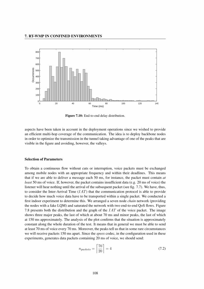
7. RT-WMP IN CONFINED ENVIRONMENTS
0 20 40 60 80 100 120 1400
100
200
300
400
500
600
700
800
Time (ms)
Occ
urre
nces
Figure 7.10: End-to-end delay distribution.
aspects have been taken in account in the deployment operations since we wished to providean efficient multi-hop coverage of the communication. The idea is to deploy backbone nodesin order to optimize the transmission in the tunnel taking advantage of one of the peaks that arevisible in the figure and avoiding, however, the valleys.
Selection of Parameters
To obtain a continuous flow without cuts or interruption, voice packets must be exchangedamong mobile nodes with an appropriate frequency and within their deadlines. This meansthat if we are able to deliver a message each 50 ms, for instance, the packet must contain atleast 50 ms of voice. If, however, the packet contains insufficient data (e.g. 20 ms of voice) thelistener will hear nothing until the arrival of the subsequent packet (see fig. 7.7). We have, thus,to consider the Inter-Arrival Time (IAT ) that the communication protocol is able to provideto decide how much voice data have to be transported within a single packet. We conducted afirst indoor experiment to determine this. We arranged a seven node chain network (providingthe nodes with a fake LQM) and saturated the network with two end-to-end QoS flows. Figure7.8 presents both the distribution and the graph of the IAT of the voice packet. The imageshows three major peaks, the last of which at about 70 ms and minor peaks, the last of whichat 150 ms approximately. The analysis of the plot confirms that the situation is approximatelyconstant along the whole duration of the test. It means that in general we must be able to sendat least 70 ms of voice every 70 ms. Moreover, the peaks tell us that in some rare circumstanceswe will receive packets 150 ms apart. Since the speex codec, in the configuration used in theseexperiments, generates data packets containing 20 ms of voice, we should send:
npackets =
⌈70
20
⌉= 4 (7.2)
108
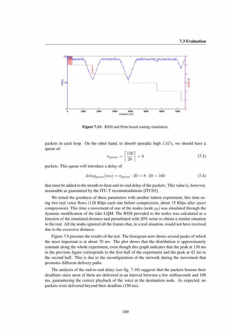
7.3 Evaluation
0 1000 2000 3000 4000 5000 6000 70000
50
100
Position (m)
RS
SI
0 1000 2000 3000 4000 5000 6000 70000
1
2
3
4
5
6
Nod
e Id
Figure 7.11: RSSI and Prim based routing simulation.
packets in each loop. On the other hand, to absorb sporadic high IAT s, we should have aqueue of:
nqueue =
⌈150
20
⌉= 8 (7.3)
packets. This queue will introduce a delay of:
delayqueue(ms) = nqueue · 20 = 8 · 20 = 160 (7.4)
that must be added to the mouth-to-hear end-to-end delay of the packets. This value is, however,assumable as guaranteed by the ITU-T recommendations [ITU03].
We tested the goodness of these parameters with another indoor experiment, this time us-ing two real voice flows (128 Kbps each one before compression, about 15 Kbps after speexcompression). This time a movement of one of the nodes (node p0) was simulated through thedynamic modification of the fake LQM. The RSSI provided to the nodes was calculated as afunction of the simulated distance and perturbated with 20% noise to obtain a similar situationto the real. All the nodes ignored all the frames that, in a real situation, would not have receiveddue to the excessive distance.
Figure 7.9 presents the results of the test. The histogram now shows several peaks of whichthe most important is at about 70 ms. The plot shows that the distribution is approximatelyconstant along the whole experiment, even though this graph indicates that the peak at 130 msin the previous figure corresponds to the first half of the experiment and the peak at 42 ms tothe second half. This is due to the reconfiguration of the network during the movement thatpromotes different delivery paths.
The analysis of the end-to-end delay (see fig. 7.10) suggests that the packets honour theirdeadlines since most of them are delivered in an interval between a few milliseconds and 100ms, guaranteeing the correct playback of the voice at the destination node. As expected, nopackets were delivered beyond their deadline (150 ms).
109

7. RT-WMP IN CONFINED ENVIRONMENTS
1p 3p 4p2p 5p
0p 6p tokenauthmessage
1
2 3 4 5
6
7
8
9101112
13last-hop sender
Figure 7.12: Identity of the last-hop sender.
(a) Node Positions
Position [m]
Nodes 1 - 2 ≈ 2000Nodes 2 - 3 ≈ 2000Nodes 3 - 4 ≈ 1200Nodes 4 - 5 ≈ 1500
(b) Test Parameters
Parameter ValuesFrequency 2.412 GHzChannel rate 6 MbpsTx Power 100 mWQoS flows rate 15 KbpsPacket size 160 bytesDeadline 150 ms
(c) Results
Flow 1 Flow 2
PDR (%) 98.2 % 97.9%MOS > 3.5 > 3.5
Table 7.1: Parameters and results of the experiment.
RSSI and Prim Based Routing
The same experiment gave us information about the effectiveness of the RSSI and Prim basedrouting algorithm. Figure 7.11 shows its behavior. The figure refers to mobile node p0 andshows the identity of the last-hop sender (that is, the identity of the node that delivered themessage to node p0) and the RSSI, considered as indicator of the link quality in this article,with which the former listens to the latter (see fig. 7.12).
The two mobile nodes (p0 and p6) start close to each other and to the node p1. Severalframes are exchanged directly between node p0 and node p6. Then, node p0 starts moving to-wards the other end of the backbone. The link quality with node p6 falls and node p0 begins toexchange frames with node p1 following the rules established by Prim’s algorithm. The sameoccurs with the subsequent nodes. As expected, the link quality with the sender is always main-tained at acceptable values. The algorithm suffers from short oscillations at the switching pointdue to RSSI noise that is, however, completely assumable by the system. In some situations,moreover, node p0 acts as a bridge between adjacent nodes, again due to the RSSI fluctuation.
7.3.2 Real Experiment
The real experiment consisted of the deployment of the cited five nodes in the Somport tunnel.Table 7.1.a shows where the backbone nodes have been deployed along the tunnel in order toprovide a suitable inter-backbone node RSSI value. The second node position, however, waschosen at the peak nearest to the tunnel slope change.
110

7.3 Evaluation
0 0.5 1 1.5 2 2.5 3
x 105
0
200
400
600
800
1000
Time (us)
Occ
urre
nces
0 1000 2000 3000 4000 5000 6000 70000
0.5
1
1.5
2x 10
5
Tim
e (u
s)
Position(m)
Figure 7.13: Distribution and raw data of Inter-Arrival Time (IAT) in the real experiment.
Two laptops running Linux OS were used as mobile nodes. The sampling of the voice sig-nal was performed accessing directly the /dev/dsp device and compressing 320 bytes of data(160 samples of 16 bit) to a 40 bytes speex packet (20 ms of voice). The packets were aggre-gated in groups of four and sent to the other mobile node and, as in the laboratory experiment,the QoS extension was configured to transport up to two QoS messages in each procol loop(see [Sicignano10a] for details). One of the mobile nodes was maintained stationary at about400 m from one end of the backbone while the other was moved, in a car, towards the otherend of the backbone maintaining the voice link at all times. The movement speed was about40 km/h. Table 7.1.b lists the parameter values used in the tests.
The most notable parameters for evaluating voice transmission are the Packet DeliveryRatio (PDR), the end-to-end delay and the variance of the voice packet inter-arrival time (jitter).The following sections show the results of the experiments.
111
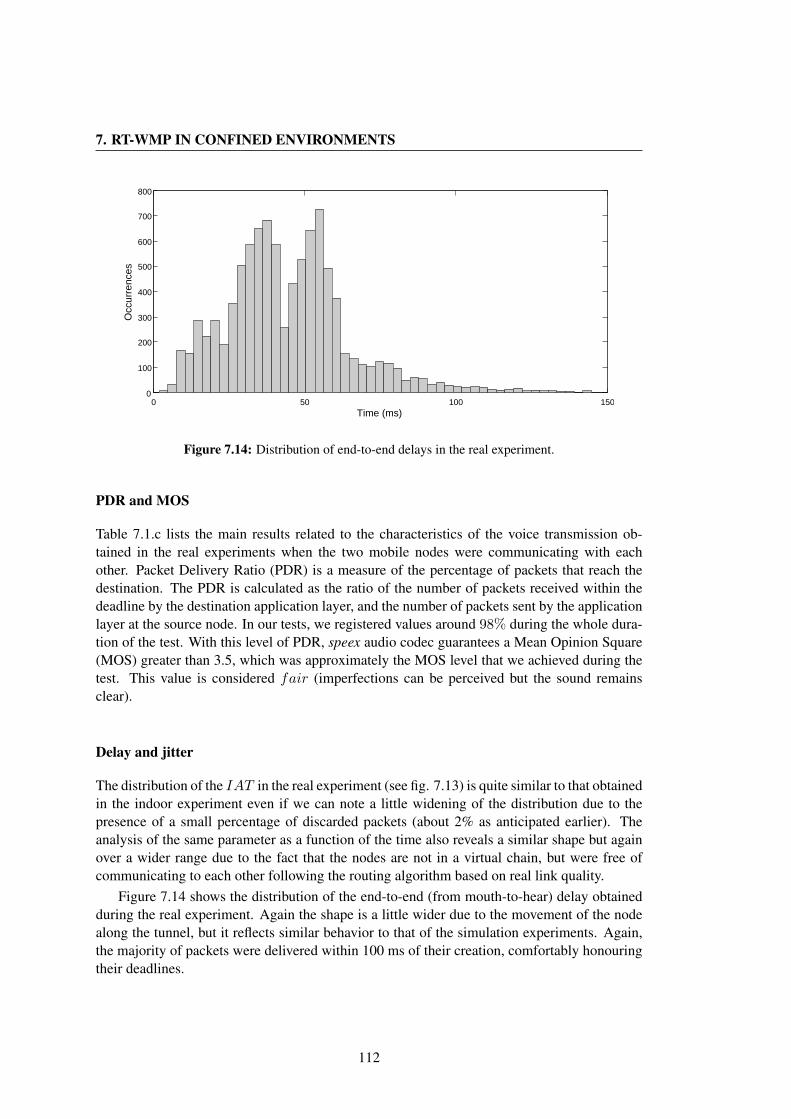
7. RT-WMP IN CONFINED ENVIRONMENTS
0 50 100 1500
100
200
300
400
500
600
700
800
Time (ms)
Occ
urre
nces
Figure 7.14: Distribution of end-to-end delays in the real experiment.
PDR and MOS
Table 7.1.c lists the main results related to the characteristics of the voice transmission ob-tained in the real experiments when the two mobile nodes were communicating with eachother. Packet Delivery Ratio (PDR) is a measure of the percentage of packets that reach thedestination. The PDR is calculated as the ratio of the number of packets received within thedeadline by the destination application layer, and the number of packets sent by the applicationlayer at the source node. In our tests, we registered values around 98% during the whole dura-tion of the test. With this level of PDR, speex audio codec guarantees a Mean Opinion Square(MOS) greater than 3.5, which was approximately the MOS level that we achieved during thetest. This value is considered fair (imperfections can be perceived but the sound remainsclear).
Delay and jitter
The distribution of the IAT in the real experiment (see fig. 7.13) is quite similar to that obtainedin the indoor experiment even if we can note a little widening of the distribution due to thepresence of a small percentage of discarded packets (about 2% as anticipated earlier). Theanalysis of the same parameter as a function of the time also reveals a similar shape but againover a wider range due to the fact that the nodes are not in a virtual chain, but were free ofcommunicating to each other following the routing algorithm based on real link quality.
Figure 7.14 shows the distribution of the end-to-end (from mouth-to-hear) delay obtainedduring the real experiment. Again the shape is a little wider due to the movement of the nodealong the tunnel, but it reflects similar behavior to that of the simulation experiments. Again,the majority of packets were delivered within 100 ms of their creation, comfortably honouringtheir deadlines.
112
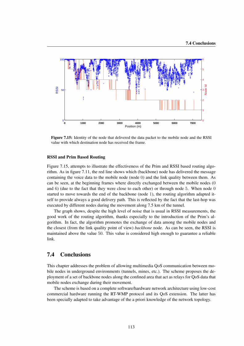
7.4 Conclusions
0 1000 2000 3000 4000 5000 6000 70000
50
100
Position (m)
RS
SI
0 1000 2000 3000 4000 5000 6000 70000
1
2
3
4
5
6
Nod
e Id
Figure 7.15: Identity of the node that delivered the data packet to the mobile node and the RSSIvalue with which destination node has received the frame.
RSSI and Prim Based Routing
Figure 7.15, attempts to illustrate the effectiveness of the Prim and RSSI based routing algo-rithm. As in figure 7.11, the red line shows which (backbone) node has delivered the messagecontaining the voice data to the mobile node (node 0) and the link quality between them. Ascan be seen, at the beginning frames where directly exchanged between the mobile nodes (0and 6) (due to the fact that they were close to each other) or through node 5. When node 0started to move towards the end of the backbone (node 1), the routing algorithm adapted it-self to provide always a good delivery path. This is reflected by the fact that the last-hop wasexecuted by different nodes during the movement along 7.5 km of the tunnel.
The graph shows, despite the high level of noise that is usual in RSSI measurements, thegood work of the routing algorithm, thanks especially to the introduction of the Prim’s al-gorithm. In fact, the algorithm promotes the exchange of data among the mobile nodes andthe closest (from the link quality point of view) backbone node. As can be seen, the RSSI ismaintained above the value 50. This value is considered high enough to guarantee a reliablelink.
7.4 Conclusions
This chapter addresses the problem of allowing multimedia QoS communication between mo-bile nodes in underground environments (tunnels, mines, etc.). The scheme proposes the de-ployment of a set of backbone nodes along the confined area that act as relays for QoS data thatmobile nodes exchange during their movement.
The scheme is based on a complete software/hardware network architecture using low-costcommercial hardware running the RT-WMP protocol and its QoS extension. The latter hasbeen specially adapted to take advantage of the a priori knowledge of the network topology.
113
7. RT-WMP IN CONFINED ENVIRONMENTS
The whole system was finally tested in the Somport tunnel (linking the old railway fromCanfranc, Spain to Pau, France) on 18 January 2010 in the presence of the tunnel crew, thedirector of the roads unit of the Huesca province and representatives of the Spanish Ministryof Public Works, with satisfactory results.
The real experiments show that this is a valid, flexible and easy-to-setup solution for sup-porting QoS flows in tunnels, mines or disaster zones where the use of infrastructure networksis impossible or too expensive. The results confirmed that the system is capable of offeringa correct and effective delivery of QoS packets within a deadline fixed at 150 ms in a 7 nodenetwork, guaranteeing a MOS above 3.5 throughout the duration of the experiment.
114

Chapter 8
The wmpSniffer
Too often, network protocols are proposed and only tested in simulated environments or withsimulation tools such as ns-2 [NS2] or OPNet [OPNET]. However, simulation results fre-quently do not agree with the real behavior of protocols, especially in wireless environmentswhere interference causes the bit error ratio (BER) to be much higher than in protocols wherethe transport medium is a cable or an optic fiber. Moreover, propagation models used for sim-ulation are too simplified and do not contemplate radio-frequency effects such as multi-path orreflections due to obstacles or particular weather conditions. On the other hand (as we havelearnt to our cost) the development of a network protocol is a very hard task. Protocols thatshould work from a theoretical point of view do not always work properly in practice due tounexpected situations or errors or even incorrect implementations. In fact, the nature of a dis-tributed system substantially complicates the analysis and evaluation of a protocol as well asdebugging. The simple desynchronization of the nodes belonging to the network, more thanprobable in distributed wireless networks, can provoke chain reactions that could destabilizethe protocol in an unpredicted/unpredictable manner. A tool is therefore necessary to imple-mentation, to fix bugs or to examine and solve specific problems in behavior. Sniffer toolssuch as wireshark [WIRESH] are very useful for analysis and evaluation but have (from ourpoint of view) some limitations in terms of graphical presentation of data. It is very difficultto understand what is actually happening in the network by only looking at the list of framespresented by the program (see fig. 8.1). Moreover, these tools are not capable of calculatingbasic parameters such as bandwidth occupied, overhead, or end-to-end delivery of messages.We could say that this type of tool represents low-level oriented applications.
To overcome these limitations, we started the development of a dedicated sniffer fromscratch. The result is the wmpSniffer, a RT-WMP sniffer and analyzer capable of showinggraphically the succession of events that take place in a RT-WMP network, offering data overeach one of the frames exchanged, analyzing results (bandwidth, overhead, end-to-end delays,etc. both numerically and graphically), representing graphically the path followed by messagesand so on. Moreover, it is capable of fusing local data collected individually by each node innot completely connected networks to obtain an almost complete dataset useful for debuggingand analysis purposes. It also allows the simulation of RT-WMP networks (in a similar wayas proposed in [Facchinetti05b]), allowing the execution of the nodes in the same machine
115

8. THE WMPSNIFFER
Figure 8.1: Some ethernet frames captured with wireshark.
while recording the frames exchanged. In this configuration, the nodes can be moved in a twodimensional view to simulate mobility and not completely connected or disconnected networks.
This tool has been used throughout the life of the RT-WMP to facilitate the development,debugging and analysis of such a protocol. It is already being used in all the experimentscarried out, in order to monitor and analyze the behavior of the protocol in any situation. Thetool can be considered as a sibling of the RT-WMP and has had a very important role in itsgrowth and, above all, on the development of its extensions.
8.1 The wmpSniffer
The wmpSniffer offers several facilities to RT-WMP developers and users. It is able to graph-ically represent and analyze any type of frame that RT-WMP nodes can exchange, includingmulticast or QoS, and inform about frames that have used the ETT mechanism. Figure 8.2shows the main window of the application. On the left upper side (2D View), there is a big
116

8.1 The wmpSniffer
Figure 8.2: Main window of wmpSniffer.
picture-box where the members of the network are represented as small figures (square witha triangle inside) with their corresponding positions (if available). Lines between the nodesrepresent the existence of a link between them and the corresponding link quality (extractedfrom the LQM) in both directions. The box below the latter (Frames view), represents theframes exchanged by the nodes. Each horizontal line corresponds to one node for which theWMP address is shown both on its right and left. Vertical arrows represent frames exchangedbetween nodes. Each color corresponds to a different type of frame (red for tokens, green forauthorizations, blue for messages and black for drops). When a frame is selected by clickingon it, all its fields are shown in the Frame Info tree-view (e.g. from, to or LQM fields). Below,two sliding selectors and a numeric textbox allow surfing among the frames recorded by theapplication. The Show Options section enables the user to choose visualization options. ThePrim checkbox causes the Minumum Spanning Tree (MST) to be calculated and shown insteadof the complete LQM in the 2D View. The Foreign option makes alien frames visible both inthe Frames and 2D View and able to be selected for analysis in the Frame Info section. TheFrames, 2D and Text checkbox allow the Frames, 2D View and Frame Info views to be enabledor disabled during recording and playing (to limit computation load). Below, the Play andRecord buttons permit network traffic to be recorded and replayed. The Statistics button pro-duces a new window showing statistics about the operations of the protocol (see next section).The Find button allows a particular frame to be searched, specifying a value of one of its fields.Finally, the Exit button terminates the program.
117
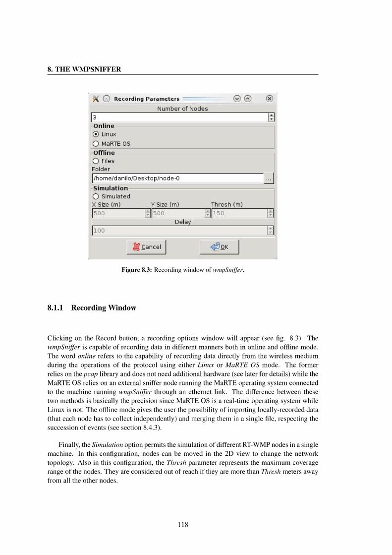
8. THE WMPSNIFFER
Figure 8.3: Recording window of wmpSniffer.
8.1.1 Recording Window
Clicking on the Record button, a recording options window will appear (see fig. 8.3). ThewmpSniffer is capable of recording data in different manners both in online and offline mode.The word online refers to the capability of recording data directly from the wireless mediumduring the operations of the protocol using either Linux or MaRTE OS mode. The formerrelies on the pcap library and does not need additional hardware (see later for details) while theMaRTE OS relies on an external sniffer node running the MaRTE operating system connectedto the machine running wmpSniffer through an ethernet link. The difference between thesetwo methods is basically the precision since MaRTE OS is a real-time operating system whileLinux is not. The offline mode gives the user the possibility of importing locally-recorded data(that each node has to collect independently) and merging them in a single file, respecting thesuccession of events (see section 8.4.3).
Finally, the Simulation option permits the simulation of different RT-WMP nodes in a singlemachine. In this configuration, nodes can be moved in the 2D view to change the networktopology. Also in this configuration, the Thresh parameter represents the maximum coveragerange of the nodes. They are considered out of reach if they are more than Thresh meters awayfrom all the other nodes.
118

8.1 The wmpSniffer
Figure 8.4: Statistic window of wmpSniffer.
119

8. THE WMPSNIFFER
Figure 8.5: Graphics obtained with wmpSniffer.
8.1.2 Statistics Window
This window shows the operational statistics of the protocol (see fig. 8.4). The tree has severalsections including general information, errors occurring during operations (drops, retries, lostmessages etc. and even a statistic about the number of frames presumed lost by the snifferin reception), and information about each one of the node-to-node flows of the session, forreal-time, multicast and QoS traffic. For each flow the mean bandwidth, the overhead and theend-to-end message delivery delay for each one of the priority levels (or classes in case of QoS)is reported. Moreover, by means of this window, it is possible to select (and isolate) the partof the data that does not contain errors, to evaluate the error-free performance. For many ofthe results, it is possible to obtain a graphical representation of the data both in the form ofdistribution and as a function of the time (see fig. 8.5).
8.2 The wmpSniffer Internal structure
The wmpSniffer is organized in a layered structure (see fig. 8.6). The lowest level layer isresponsible for physically sniffing the medium. It relies on two different mechanisms. The firstis based on the pcap library. To utilize this configuration, the wireless network card must beconfigured in monitor mode to be able to receive any type of frame. The RT-WMP frames arenot, in fact, standard TCP/IP frames but lean directly over 802.11 frames. The frames sniffedby the library are then received by the low level layer that is responsible for providing them tothe buffer layer. A second method relies on the use of an external MaRTE OS based sniffer that
120
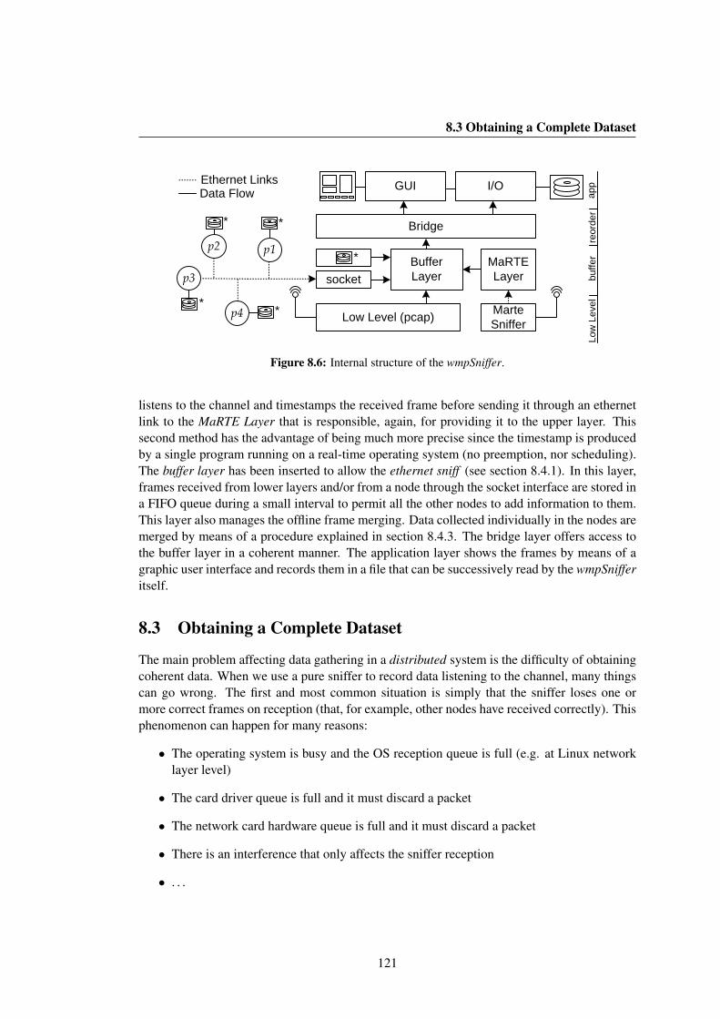
8.3 Obtaining a Complete Dataset
Low Level (pcap) Marte Sniffer
BufferLayer
p2
p3
p4
p1MaRTELayer
Bridge
I/O
socket
*
**
* *
GUIEthernet LinksData Flow
Low
Lev
elbu
ffer
reor
der
app
Figure 8.6: Internal structure of the wmpSniffer.
listens to the channel and timestamps the received frame before sending it through an ethernetlink to the MaRTE Layer that is responsible, again, for providing it to the upper layer. Thissecond method has the advantage of being much more precise since the timestamp is producedby a single program running on a real-time operating system (no preemption, nor scheduling).The buffer layer has been inserted to allow the ethernet sniff (see section 8.4.1). In this layer,frames received from lower layers and/or from a node through the socket interface are stored ina FIFO queue during a small interval to permit all the other nodes to add information to them.This layer also manages the offline frame merging. Data collected individually in the nodes aremerged by means of a procedure explained in section 8.4.3. The bridge layer offers access tothe buffer layer in a coherent manner. The application layer shows the frames by means of agraphic user interface and records them in a file that can be successively read by the wmpSnifferitself.
8.3 Obtaining a Complete Dataset
The main problem affecting data gathering in a distributed system is the difficulty of obtainingcoherent data. When we use a pure sniffer to record data listening to the channel, many thingscan go wrong. The first and most common situation is simply that the sniffer loses one ormore correct frames on reception (that, for example, other nodes have received correctly). Thisphenomenon can happen for many reasons:
• The operating system is busy and the OS reception queue is full (e.g. at Linux networklayer level)
• The card driver queue is full and it must discard a packet
• The network card hardware queue is full and it must discard a packet
• There is an interference that only affects the sniffer reception
• . . .
121
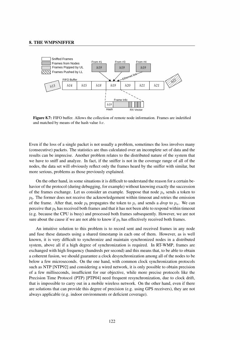
8. THE WMPSNIFFER
h13 h14 h19h18h15 h20 h21
From #1
h21
h19 h19 h19
Ethernet link
From #3 From #4
FIFO Buffer
RX Vector
Frame Info
Frames Popped by ULFrames from NodesSniffed Frames
h22
Frames Pushed by LL
h19Hash
Figure 8.7: FIFO buffer. Allows the collection of remote node information. Frames are indetifiedand matched by means of the hash value hx.
Even if the loss of a single packet is not usually a problem, sometimes the loss involves many(consecutive) packets. The statistics are thus calculated over an incomplete set of data and theresults can be imprecise. Another problem relates to the distributed nature of the system thatwe have to sniff and analyze. In fact, if the sniffer is not in the coverage range of all of thenodes, the data set will obviously reflect only the frames heard by the sniffer with similar, butmore serious, problems as those previously explained.
On the other hand, in some situations it is difficult to understand the reason for a certain be-havior of the protocol (during debugging, for example) without knowing exactly the successionof the frames exchange. Let us consider an example. Suppose that node pa sends a token topb. The former does not receive the acknowledgement within timeout and retries the emissionof the frame. After that, node pb propagates the token to pc and sends a drop to pa. We canperceive that pb has received both frames and that it has not been able to respond within timeout(e.g. because the CPU is busy) and processed both frames subsequently. However, we are notsure about the cause if we are not able to know if pb has effectively received both frames.
An intuitive solution to this problem is to record sent and received frames in any nodeand fuse these datasets using a shared timestamp in each one of them. However, as is wellknown, it is very difficult to synchronize and maintain synchronized nodes in a distributedsystem, above all if a high degree of synchronization is required. In RT-WMP, frames areexchanged with high frequency (hundreds per second) and this means that, to be able to obtaina coherent fusion, we should guarantee a clock desynchronization among all of the nodes to bebelow a few microseconds. On the one hand, with common clock synchronization protocolssuch as NTP [NTP92] and considering a wired network, it is only possible to obtain precisionof a few milliseconds, insufficient for our objective, while more precise protocols like thePrecision Time Protocol (PTP) [PTP04] need frequent resynchronization, due to clock drift,that is impossible to carry out in a mobile wireless network. On the other hand, even if thereare solutions that can provide this degree of precision (e.g. using GPS receivers), they are notalways applicable (e.g. indoor environments or deficient coverage).
122
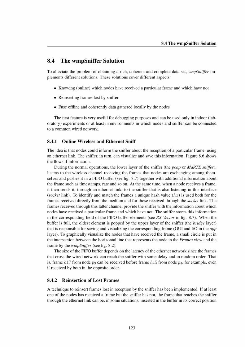
8.4 The wmpSniffer Solution
8.4 The wmpSniffer Solution
To alleviate the problem of obtaining a rich, coherent and complete data set, wmpSniffer im-plements different solutions. These solutions cover different aspects:
• Knowing (online) which nodes have received a particular frame and which have not
• Reinserting frames lost by sniffer
• Fuse offline and coherently data gathered locally by the nodes
The first feature is very useful for debugging purposes and can be used only in indoor (lab-oratory) experiments or at least in environments in which nodes and sniffer can be connectedto a common wired network.
8.4.1 Online Wireless and Ethernet Sniff
The idea is that nodes could inform the sniffer about the reception of a particular frame, usingan ethernet link. The sniffer, in turn, can visualize and save this information. Figure 8.6 showsthe flows if information.
During the normal operations, the lower layer of the sniffer (the pcap or MaRTE sniffer),listens to the wireless channel receiving the frames that nodes are exchanging among them-selves and pushes it in a FIFO buffer (see fig. 8.7) together with additional information aboutthe frame such as timestamps, rate and so on. At the same time, when a node receives a frame,it then sends it, through an ethernet link, to the sniffer that is also listening in this interface(socket link). To identify and match the frames a unique hash value (hx) is used both for theframes received directly from the medium and for those received through the socket link. Theframes received through this latter channel provide the sniffer with the information about whichnodes have received a particular frame and which have not. The sniffer stores this informationin the corresponding field of the FIFO buffer elements (see RX Vector in fig. 8.7). When thebuffer is full, the oldest element is popped by the upper layer of the sniffer (the bridge layer)that is responsible for saving and visualizing the corresponding frame (GUI and I/O in the applayer). To graphically visualize the nodes that have received the frame, a small circle is put inthe intersection between the horizontal line that represents the node in the Frames view and theframe by the wmpSniffer (see fig. 8.2).
The size of the FIFO buffer depends on the latency of the ethernet network since the framesthat cross the wired network can reach the sniffer with some delay and in random order. Thatis, frame h17 from node p3 can be received before frame h15 from node p4, for example, evenif received by both in the opposite order.
8.4.2 Reinsertion of Lost Frames
A technique to reinsert frames lost in reception by the sniffer has been implemented. If at leastone of the nodes has received a frame but the sniffer has not, the frame that reaches the snifferthrough the ethernet link can be, in some situations, inserted in the buffer in its correct position
123

8. THE WMPSNIFFER
s7 (h1) s12 (h6)s9 (h3)s8 (h2) s13 (h7)s6 (h0)
s10 (h4)Frames to ReinsertSniffed Frames s11 (h5)
s15 (h9)
s14 (h8)
Figure 8.8: Reinsertion of lost frames using serial field and heuristic.
by means of a simple heuristic that takes into account the frames serial and the inter-framedelay (see fig. 8.8).
Notice that only received frames can be taken into account. Often, in fact, transmittingnodes have a different perception of the succession of events than the receiving nodes, aboveall in the presence of errors. Let us consider an example. Suppose that pa node needs to send aframe. The RT-WMP core calls the corresponding low-level function that in turn provokes thenetwork card to begin the transmission procedure. As the 802.11 protocol specifies, the cardstarts to listen to the channel waiting at least a DIFS before transmitting. However, if someerror has occurred previously, the channel can be occupied by a pb transmission. The pa nodenetwork card receives the pb frame (f1) and stores it in the reception queue. When the mediumis free, pa emits its frame (f2) and then processes the f1. It has, thus, the perception that thesuccession of frames is f2 and then f1 while the rest of the network has the correct perception(f1 and then f2). Considering received frames only means that this common problem can beavoided, although it does not solve the the double hidden node problem. In fact, it is possiblethat the pa neighbor listened f2 while the pb node listened to f1 instead.
8.4.3 Offline Frame Merge
The third and very interesting characteristic is that which permits fusing offline data collectedlocally by different nodes. This feature is particularly useful in situations in which other meth-ods of data gathering are not possible (e.g. outdoor scenarios with mobile nodes and/or sparsenetworks). In this configuration, nodes record all the received frames individually during theirnormal operation. The objective is to fuse all the frames into a single dataset, maintaining thesuccession of events and delays among them, in order to be able to analyze the protocol behav-ior and performance correctly. We consider this to be a very important issue both for debuggingand analysis purposes. We consider two different ways of obtaining a single dataset, throughoffline clock synchronization and event based reordering.
Offline Synchronization
This first technique relies on the fact that when a node emits a frame, all the nodes in thecoverage range receive it at exactly the same moment. Utilizing these syncronization pointswe could, theoretically, synchronize the node clock offline. At the beginning, we could syn-chronize neighbor nodes in relation to each other. Frames listened by the pa and pb nodes, forinstance, could be used to synchronize these two nodes. Then, the frames listened to by pb andpc could be used to synchronize pb with pc and, indirectly, with pa, etc. In this way we could
124
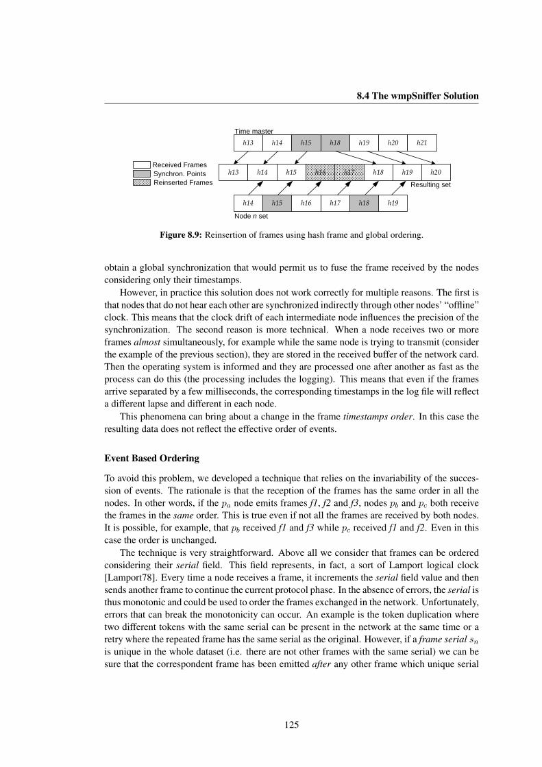
8.4 The wmpSniffer Solution
h13 h14 h17h16h15 h18 h19
h19h17h14 h18h16h15
h13 h14 h19h18h15 h20 h21
h20
Time master
Node n set
Resulting setReinserted FramesSynchron. PointsReceived Frames
Figure 8.9: Reinsertion of frames using hash frame and global ordering.
obtain a global synchronization that would permit us to fuse the frame received by the nodesconsidering only their timestamps.
However, in practice this solution does not work correctly for multiple reasons. The first isthat nodes that do not hear each other are synchronized indirectly through other nodes’ “offline”clock. This means that the clock drift of each intermediate node influences the precision of thesynchronization. The second reason is more technical. When a node receives two or moreframes almost simultaneously, for example while the same node is trying to transmit (considerthe example of the previous section), they are stored in the received buffer of the network card.Then the operating system is informed and they are processed one after another as fast as theprocess can do this (the processing includes the logging). This means that even if the framesarrive separated by a few milliseconds, the corresponding timestamps in the log file will reflecta different lapse and different in each node.
This phenomena can bring about a change in the frame timestamps order. In this case theresulting data does not reflect the effective order of events.
Event Based Ordering
To avoid this problem, we developed a technique that relies on the invariability of the succes-sion of events. The rationale is that the reception of the frames has the same order in all thenodes. In other words, if the pa node emits frames f1, f2 and f3, nodes pb and pc both receivethe frames in the same order. This is true even if not all the frames are received by both nodes.It is possible, for example, that pb received f1 and f3 while pc received f1 and f2. Even in thiscase the order is unchanged.
The technique is very straightforward. Above all we consider that frames can be orderedconsidering their serial field. This field represents, in fact, a sort of Lamport logical clock[Lamport78]. Every time a node receives a frame, it increments the serial field value and thensends another frame to continue the current protocol phase. In the absence of errors, the serial isthus monotonic and could be used to order the frames exchanged in the network. Unfortunately,errors that can break the monotonicity can occur. An example is the token duplication wheretwo different tokens with the same serial can be present in the network at the same time or aretry where the repeated frame has the same serial as the original. However, if a frame serial snis unique in the whole dataset (i.e. there are not other frames with the same serial) we can besure that the correspondent frame has been emitted after any other frame which unique serial
125

8. THE WMPSNIFFER
Node p set
Reinserted FramesSynchron. PointsReceived Frames
=+
+
= h18h14 h19h17h15
Node q set
=
h13 h14 h19h18h15 h20Time master
h17h14 h19h16h15
h17h14 h19h16h15
Node p set
+
=
Resulting set (I)
Resulting set (II)
Resulting set (III)
h13 h14 h17h16h15 h19 h20h18
h13 h14 h18h17h15 h20h19
h13 h14 h15 h18 h19 h20
a)
b)
c)
d)
=
=
Figure 8.10: Recursive reinsertion using global ordering.
sy has a value lower than sn.We thus prepare a first ordered dataset containing all the frames with unique serial obtained
by the different nodes’ dataset. It is called time master set (Stm). The Stm represent a big partof the whole dataset even in sparse networks since (it is supposed that) the network is workingthe majority of the time without errors. The frames are identified by means of a unique hashvalue. Then, all the individual node datasets are analyzed one after another. In general, manyframes are present in both in Stm and in the node sets. Let us suppose that Stm and Sn containthe following hash values hn (see fig. 8.9):
Stm = h13 h14 h15 h18 h19, Sn = h14 h15 h16 h17 h18h19 (8.1)
Since both frames h15 and h18 have been received simultaneously in all the nodes inthe coverage range, we can be sure that frames h16 and h17 have been transmitted, in thisorder, between frames h15 and h18. Thus, they can be reinserted in the global data set, usingh15 and h18 as synchronization points. All the available sets of data are analyzed to reinsertthe maximum possible number of frames. Moreover, the process is recursive since there aresituations in which the reinsertion is more complicated. Let us consider the following example(see fig. 8.10):
Stm = h13 h14 h15 h18 h19 h20, Sp = h14 h15 h16 h17 h19 (8.2)
In this case, even if h15 and h19 are still synchronization points, we can not know withcertainty the relative order of h16, h17 and h18. Here the resulting set is not modified andremains equal to the time master set. However, there could exist a third set Sq:
Sq = h14 h15 h17 h18 h19 (8.3)
that can be used to infer the order of h17 and h18 and reinsert the frame h17. If now theSp set is used again, it is possible to infer the h16 position and reconstruct the complete dataset. As just explained, the process is recursive and ends only when is not possible to reinsertany frame. Sometimes, however, situations exist in which it is not possible to reconstruct
126
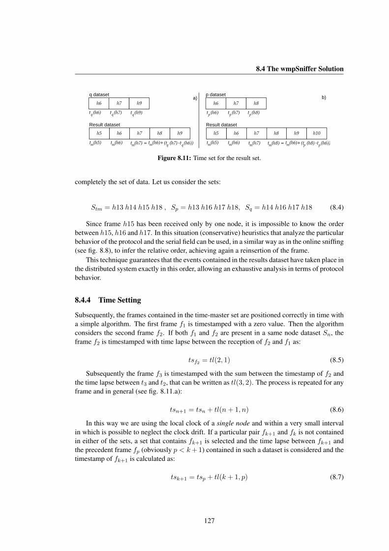
8.4 The wmpSniffer Solution
h7 h9h6
h6 h9h8h7h5
t (h6)mt (h5)m (t (h7)q t (h6)qt (h7)m = t (h6)m + )-
t (h6)q t (h7)q t (h9)q
h6 h9h8h7 h10h5
t (h6)mt (h5)m t (h7)m
h7 h8h6
t (h6)p t (h7)p t (h8)p
(t (h8)p t (h6)pt (h8)m = t (h6)m + )-
a) b)
Result dataset Result dataset
q dataset p dataset
Figure 8.11: Time set for the result set.
completely the set of data. Let us consider the sets:
Stm = h13 h14 h15 h18 , Sp = h13 h16 h17 h18, Sq = h14 h16 h17 h18 (8.4)
Since frame h15 has been received only by one node, it is impossible to know the orderbetween h15, h16 and h17. In this situation (conservative) heuristics that analyze the particularbehavior of the protocol and the serial field can be used, in a similar way as in the online sniffing(see fig. 8.8), to infer the relative order, achieving again a reinsertion of the frame.
This technique guarantees that the events contained in the results dataset have taken place inthe distributed system exactly in this order, allowing an exhaustive analysis in terms of protocolbehavior.
8.4.4 Time Setting
Subsequently, the frames contained in the time-master set are positioned correctly in time witha simple algorithm. The first frame f1 is timestamped with a zero value. Then the algorithmconsiders the second frame f2. If both f1 and f2 are present in a same node dataset Sn, theframe f2 is timestamped with time lapse between the reception of f2 and f1 as:
tsf2 = tl(2, 1) (8.5)
Subsequently the frame f3 is timestamped with the sum between the timestamp of f2 andthe time lapse between t3 and t2, that can be written as tl(3, 2). The process is repeated for anyframe and in general (see fig. 8.11.a):
tsn+1 = tsn + tl(n+ 1, n) (8.6)
In this way we are using the local clock of a single node and within a very small intervalin which is possible to neglect the clock drift. If a particular pair fk+1 and fk is not containedin either of the sets, a set that contains fk+1 is selected and the time lapse between fk+1 andthe precedent frame fp (obviously p < k+1) contained in such a dataset is considered and thetimestamp of fk+1 is calculated as:
tsk+1 = tsp + tl(k + 1, p) (8.7)
127
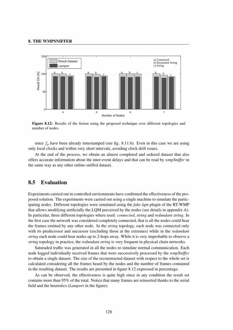
8. THE WMPSNIFFER
4 5 6 70
50
100
150
a b ca b c
a b c a bc
Number of Nodes
Res
ult D
S (
%)
Result Dataset
Lamport
a) Connectedb) Resundant Stringc) String
Figure 8.12: Results of the fusion using the proposed technique over different topologies andnumber of nodes.
since fp have been already timestamped (see fig. 8.11.b). Even in this case we are usingonly local clocks and within very short intervals, avoiding clock drift issues.
At the end of the process, we obtain an almost completed and ordered dataset that alsooffers accurate information about the inter-event delays and that can be read by wmpSniffer inthe same way as any other online-sniffed dataset.
8.5 Evaluation
Experiments carried out in controlled environments have confirmed the effectiveness of the pro-posed solution. The experiments were carried out using a single machine to simulate the partic-ipating nodes. Different topologies were simulated using the fake lqm plugin of the RT-WMPthat allows modifying artificially the LQM perceived by the nodes (see details in appendix A).In particular, three different topologies where used: connected, string and redundant string. Inthe first case the network was considered completely connected, that is all the nodes could hearthe frames emitted by any other node. In the string topology, each node was connected onlywith its predecessor and successor (excluding those at the extremes) while in the redundantstring each node could hear nodes up to 2-hops away. While it is very improbable to observe astring topology in practice, the redundant string is very frequent in physical chain networks.
Saturaded traffic was generated in all the nodes to simulate normal communication. Eachnode logged individually received frames that were successively processed by the wmpSnifferto obtain a single dataset. The size of the reconstructed dataset with respect to the whole set iscalculated considering all the frames heard by the nodes and the number of frames containedin the resulting dataset. The results are presented in figure 8.12 expressed in percentage.
As can be observed, the effectiveness is quite high since in any condition the result setcontains more than 95% of the total. Notice that many frames are reinserted thanks to the serialfield and the heuristics (Lamport in the figure).
128

8.6 Conclusions
8.6 Conclusions
In this chapter we have presented a tool for analyzing and evaluating the RT-WMP protocoland its extensions. This tool is capable of sniffing the wireless medium (both directly andby means of an external node) and representing graphically the succession of events (frameexchange) of such a protocol offering detailed numerical and graphical operational statisticsfor the basic protocol and all of its extensions. Moreover, it is capable of merging local datacollected in different unsynchronized nodes to obtain an almost complete dataset. This lasttechnique, useful for debugging and performance analysis, has been analyzed with interestingresults. More than 95% of the frames exchanged by the nodes were reflected in the resultdataset regardless of the network topology or the number of nodes.
129

8. THE WMPSNIFFER
130

Conclusions
In this thesis, we have presented a complete platform for real-time and QoS communications(both unicast and multicast) in mobile ad-hoc networks especially oriented towards mobilerobotics, developed within the framework of the EXPRES, NERO and TESSEO Spanish Na-tional Projects and the URUS project of the European Commission.
The main contribution consists in the development of a novel wireless real-time protocolcapable of delivering real-time messages over multi-hop paths managing message priorities. Ituses a token-passing scheme to guarantee bounded transmission times in the absence of errors.
The protocol deals with frequent topology changes through the sharing of a matrix thatdescribes the link quality among nodes. The protocol is capable of managing different types oferrors such as token loss, token duplication and node reincorporation after a single or multiplefailure, without losing its real-time characteristics in most cases. Both theoretical and realanalysis show that RT-WMP offers a bandwidth similar or better than that offered by the 802.11plain protocol in worst-case multi-hop situations, and comparable to it in relatively small andcompletely connected networks maintaining real-time behavior.
The results of this development were presented at the fourth IEEE International Conferenceon Mobile Ad-hoc and Sensor Systems held in Pisa, Italy in October 2007 together with thepublication “Real Time Communication over 802.11: RT-WMP” [Tardioli07], and as proof ofconcept application in the paper entitled “Distributed implementation of discrete event controlsystems based on Petri Nets” [Piedrafita08] presented at the 2008 International Symposium onIndustrial Electronics held in Cambridge, United Kingdom, between June and July 2008.
The RT-WMP has also been adopted by the robotic team of the Robotics, Perception andReal-Time Group (RoPERT) of the University of Zaragoza to carry out real-time communica-tions and for use in many real indoor and outdoor applications detailed in this thesis.
The protocol has been successively extended to manage multicast and broadcast flows, thusadding the possibility of managing simultaneously two independent flows of real-time data, oneunicast and the other multicast/broadcast. The extension manages multicast fixed priorities andmessage preemption, and offers the capability of delivering messages with bounded and knownworst-case delay. In addition, the extension can be configured to be used as a standalone uni-cast/multicast protocol, called RT-WMP+, with similar characteristics to RT-WMP. It providesbetter performance in some concrete configurations depending on the number of nodes, thedata rate and maximum transmission unit (MTU) size, and better mean behavior. The satis-factory results of the tests and experiments have been reflected in a paper entitled “Addingmulticast capabilities to wireless multi-hop token-passing protocols: Extending the RT-WMP”
131

CONCLUSIONS
[Tardioli09] presented in the 15th IEEE International Conference on Emerging Technologiesand Factory Automation held in Palma de Mallorca, Spain in August 2009.
This extension continues to be used in many multi-robot applications by the RoPERTgroup, especially in formation movement and cooperative navigation and localization that re-quires an intensive exchange of time-sensitive data among the team members (see [Urcola08],[Urcola09] and [Lazaro10]).
The need for multimedia flow support in addition to real-time support (one can think ofsituations involving humans such as rescues in disaster scenarios, for example), has led us toevaluate the possibility of offering Quality of Service (QoS) together with real-time support.This necessity motivated the development of a QoS extension to the protocol. This additionalcapability offers the possibility of establishing voice and video links among mobile nodes with-out altering the worst-case characteristics of the RT-WMP. It takes advantage of the fact that thebasic protocol works in worst-case situations in very few cases. This extension uses this unusedtime to transport one or more variable-priority messages enabling the protocol to manage mul-timedia traffic. This novel capability includes a technique to control the access to the networkof new flows based on the estimated unused time available. The solution has been implementedand evaluated. The interesting results were published in the book “Ad-hoc net- works, lecturenotes of the institute for computer sciences, social informatics and telecommunications engi-neering” [Sicignano10a] in 2010 and presented at the First International Conference on Ad-hocNetworks held in Niagara Falls, Canada in August 2009.
This extension has also been used in many real experiments involving robots and in asuccessful attempt to offer voice coverage to mobile nodes in the Somport railway tunnel (nearCanfranc, Spain) as detailed in chapter 7.
Awareness of the difficulty of supporting wireless real-time traffic, but above all the im-possibility of having an interference-free channel in some situations, has led us to considerthe problem of offering some timing guarantees in non-optimal scenarios. We have thereforecontributed a technique to make token-passing based protocols more tolerant to alien traffic orinterference. This technique relies on a dynamic acknowledgment timeout that extends (up toa maximum value) in the presence of external traffic in the same collision domain. It allowsbelated acknowledgments to be accepted in any case. This technique has been tested in indoorexperiments demonstrating its ability to reduce substantially the number of protocol errors evenin heavy alien-traffic loads, with only a little worsening in terms of end-to-end message deliverydelay. These satisfactory results are described in a contribution entitled “Adding alien trafficendurance to wireless token-passing real-time protocols” [Tardioli10a] accepted for its presen-tation at the 2010 IEEE Asia-Pacific Services Computing Conference to be held in Hangzhou(China) in December 2010.
This thesis also describes two applications of the proposed solutions and techniques thatdemonstrate the effectiveness of the RT-WMP and its extensions.
The first application consists of a complete platform for cooperative robotics. This platformpresents a technique for carrying out a set of task without losing the connectivity of the networkat any moment. This is a three layer solution in which the lower level manages communicationusing the RT-WMP and offers information about the network topology from the link-qualitypoint of view. The upper layers deal with safe movement generation (to avoid network splits)
132

CONCLUSIONS
and task allocation/reallocation. During the development of the platform, some extra character-istics were added to the RT-WMP. An additional broadcast scheme (with bounded propagationdelay) permitted the sharing of small quantities of data, allowing the nodes to have an up-to-date view of the physical topology of the network. The platform has been implemented andtested both with simulation and real experiments whose results were given in the article “En-forcing network connectivity in robot team missions” [Tardioli10b] published in the April 2010issue of the International Journal of Robotics Research and also presented during the invitedlecture “Task allocation for NRS with enforced connectivity by cooperative navigation” at theWorkshop on Network Robot Systems of the International Conference on Intelligent Robotsand Systems (IROS) held in San Diego, California in October, 2007 [Mosteo07a].
The second application shows both the capabilities of mobility management and QoS com-munication of the protocol. The experiments were designed to demonstrate that RT-WMPjointly with its QoS extension is a valid framework to offer simultaneous real-time and multi-media communication in confined areas like tunnels or mines. In the experiment, a set of nodeswere deployed along the Somport tunnel (the old railway link that connected in the past Can-franc, Spain with France) and placed at strategic points to act as backbone relay nodes for twofreely moving mobile stations. The final experiment, carried out in the presence of the tunnelcrew, the director of the roads unit of the province of Huesca and representatives of the SpanishMinistry of Public Works, consisted in establishing a voice link between the two mobile nodes,one of which was moving along a stretch of about 7.5 km of the 7.7 km tunnel at a considerablespeed. The special characteristics of the environment led us to develop a specialization of theRT-WMP routing algorithm to work in a more effective manner in a string configuration. The(link-quality) topology of the network was reduced to a minimum spanning tree using Prim’salgorithm. In this way, the nodes had the perception that the network was constituted by a setof backbone nodes (connected by strong links) and two mobile stations freely moving alongthe tunnel and free of connection with any of the backbone nodes.
The results were satisfactory. Voice communication was clear and with no interruptions,demonstrating the validity of the improved routing algorithm and the effectiveness of thevariable-priority delivery algorithm, as shown througout this thesis. The data collected duringthe experiment were summarised in a contribution entitled “RT-WMP in Underground Com-munication” [Sicignano10b] accepted for presentation at the third International Conference onWireless Communications in Underground and Confined Areas to be held in Val-d’Or, Canada,in August 2010, postponed, at the present.
While the thesis and its chapters have a more or less chronological order, we have beendeveloping, in parallel with the RT-WMP and its extensions/improvements, a tool that helps toanalyze and debug the protocol. This tool, called wmpSniffer, has the capability of sniffing thewireless medium and represents the frames in a graphical interface for inspection and to ana-lyze the behavior of the protocol. The wmpSniffer is capable of elaborating complex statisticsand visualizing them. Moreover, the tool proposes several techniques to reconstruct a completeset of data starting from a set of unsynchronized local data and allowing, in this way, a deeperanalysis of information collected in real experiments. This is a very powerful capability since,as is well known, the debugging of distributed systems is a very hard task due, among otherthings, to the difficulty of a correct and precise synchronization among nodes and to the im-
133
CONCLUSIONS
possibility, in some circumstances, of collecting all the frames exchanged with a single item ofequipment (when, for example, not all the nodes are in the same collision domain).
To summarize, we have developed and implemented a complete framework for real-timeunicast/multicast multi-hop communication offering, moreover, the possibility of managementof integrated QoS flows. We have developed a method to make the system more tolerant toalien traffic and demonstrated the effectiveness of the solution both with several extensive realexperiments and with publications in international conferences and journals.
The work does not end with this thesis. In fact, several other improvements are on thestocks or are currently being developed.
Future work
We have demonstrated throughout this thesis and with several experimental results that RT-WMPand its extensions are a good choice for real-time and QoS communications in MANETs with arelatively small number of members. However, being a three phase protocol, it unquestionablyadds a significant bandwidth overhead.
The major problem is the n2 dependency of the token size on the number of nodes (the sizeof the LQM is just n ·n) that provokes the exponential growth of the frame size limiting, aboveall, the scalability of the protocol for larger networks.
The problem of the overhead introduced by the three phases has been partially solved forsome concrete scenarios (that depend on the data rate and size, number of nodes, etc.) with thedevelopment of RT-WMP+. However, the problem of the scalability persists.
For this reason, we have recently begun to study an alternative solution in order to reducethe frame size to a linear dependency on the number of nodes, taking advantage of the possi-bility of describing satisfactorily the topology of the network with a spanning tree in a similarway as set out for the scenario described in chapter 7. The approach is promising and somepreliminary tests have been carried out with interesting results. Another interesting route is thedefinition of a multicast technique for QoS messages to allow conference-style communicationamong multiple users.
Finally, a technique to allow a dynamic change in the number of nodes is also being devel-oped. This technique permits a maximum number of nodes to be established for a network inany execution, while actively using only a subset of them. The other nodes can be successivelyincorporated to the network using a real-time proof procedure. In the same manner nodes canleave the network transparently maintaining the global real-time behavior of the network.
Furthermore, we are currently collaborating with the Universidad de Cantabria to formalisethe protocol and to obtain a MAST (an Open Environment for Modeling, Analysis, and Designof Real-Time Systems) [Harbour01] model and facilitate RT-WMP use in processes of real-time planning and scheduling.
134
Conclusiones
En esta tesis, hemos presentado una plataforma completa para comunicaciones de tiempo real(tanto unicast como multicast) y Calidad de Servicio (QoS) en redes moviles ad-hoc, espe-cialmente orientada a la robotica movil y desarrollada en el marco de los proyecto nacionalesEXPRES, NERO y TESSEO y el proyecto de la Comision Europea URUS. La contribucionprincipal consiste en el desarrollo de un nuevo protocolo inalambrico llamado Real-Time Wire-less Multi-hop Protocol (RT-WMP) capaz de entregar mensajes en tiempo real en redes multi-salto gestionando la prioridad de los mensajes. Se utiliza un esquema de paso de testigo quegarantiza, en ausencia de errores, la entrega de los mensajes en tiempo acotado y conocido.
El protocolo es capaz de gestionar frecuentes cambios de topologıa de la red medianteel intercambio de una matriz que describe la calidad de los enlaces entre los nodos. Ademasprovee al usuario con unos mecanismos para resolver situaciones de error debidas a la perdida oa la duplicacion del token o errores de transmision y es capaz de reincorporar los nodos despuesde un fallo simple o multiple sin perder sus caracterısticas de tiempo real en la mayorıa de lassituaciones.
Tanto el analisis teorico como el practico, demuestran que RT-WMP ofrece un ancho debanda similar o mejor que el ofrecido por el protocolo 802.11 en configuraciones de peor casoy comparable con el en redes pequenas completamente conexas, manteniendo, sin embargo,las caracterısticas de tiempo real en cualquier situacion.
Los resultados de este desarrollo fueron presentados en la cuarta International Conferenceon Mobile Ad-hoc and Sensor Systems celebrada en Pisa, Italia, en Octubre de 2007 con lapublicacion “Real Time Communication over 802.11: RT-WMP” [Tardioli07] y como pruebade concepto en la publicacion “Distributed implementation of discrete event control systemsbased on Petri Nets” [Piedrafita08] presentada en el International Symposium on IndustrialElectronics celebrado en Cambridge, Reino Unido, entre Junio y Julio de 2008.
El protocolo RT-WMP ha sido adoptado tambien como protocolo de comunicacion en elequipo de robots del grupo de Robotica, Percepcion y Tiempo Real (RoPERT) de la Univer-sidad de Zaragoza, con el fin de proporcionar soporte para las comunicaciones de tiempo realy para su uso en aplicaciones reales tanto para entornos interiores como exteriores como sedetalla en esta tesis.
El protocolo ha sido ampliado sucesivamente mediante una extension llamada PrioritizedMulticast Extension (PME) para manejar flujos multicast, haciendolo capaz de gestionar si-multaneamente dos flujos independientes de datos de tiempo real: uno unicast y otro multicast.De hecho esta gestiona mensajes multicast con prioridad fija y permite la expulsion temporanea
135

CONCLUSIONES
de los mismos de la red (preemption) garantizando su entrega con un retardo acotado y cono-cido.
Dicha extension puede ser configurada para ser utilizada como un protocolo unicast ymulticast independiente, denominado RT-WMP+, con caracterısticas similares a RT-WMP.Este proporciona un mejor rendimiento en algunas configuraciones concretas en funcion delnumero de nodos, de la velocidad de la red y de la unidad de transmision maxima (MTU),y mejor comportamiento medio. Los satisfactorios resultados de las pruebas y de los exper-imentos se han reflejado en un documento titulado “Adding multicast capabilities to wirelessmulti-hop token-passing protocols: Extending the RT-WMP” [Tardioli09] presentado en la 15thIEEE International Conference on Emerging Technologies and Factory Automation celebra-da en Palma de Mallorca, Espana, en Agosto de 2009. Esta extension se sigue utilizando enmuchas aplicaciones multi-robot en el RoPERT, especialmente en aplicaciones de movimientoen formacion, percepcion y navegacion cooperativa que requieren un intenso intercambio de in-formaciones sensibles al retardo entre los miembros del equipo (vease [Urcola08], [Urcola09]y [Lazaro10]).
La necesidad de soporte para flujos multimedia, ademas del soporte para trafico en tiem-po real (se puede pensar en situaciones que involucran seres humanos, tales como rescates ensituaciones de desastre, por ejemplo), nos ha llevado a evaluar la posibilidad de ofrecer Calidadde Servicio, junto con soporte de trafico de tiempo real. Esta necesidad motivo el desarrollode una extension de QoS para el protocolo. Esta capacidad adicional ofrece la posibilidad deestablecer enlaces de voz y video entre nodos moviles sin alterar las caracterısticas de peorcaso de RT-WMP. Esta extension se basa en el hecho de que el protocolo basico trabaja soloesporadicamente en situaciones de peor caso, ası que la diferencia de tiempo entre el caso nor-mal y el peor caso se puede aprovechar para enviar mensajes de prioridad variable, ofreciendode esta forma la posibilidad de transportar trafico multimedia. Esta nueva caracterıstica incluyeuna tecnica para controlar el acceso a la red de nuevos flujos QoS si ya existen otros que estanutilizando todos los recursos disponibles. La extension de QoS ha sido implementada y evalua-da. Los interesantes resultados han sido publicados en el libro “Ad-hoc networks, lecture notesof the institute for computer sciences, social informatics and telecommunications engineering”[Sicignano10a] en 2010 y presentados en la First International Conference on Ad-hoc Net-works celebrada en Niagara Falls, Canada, en Agosto de 2009. Ademas esta novedosa tecnicaha sido usada en numerosos experimentos reales con robots y en el exitoso intento de ofrecercomunicacion de voz en el antiguo tunel de ferrocarriles del Canfranc que unıa en el pasadoEspana y Francia como se detalla en el capıtulo 7.
La dificultad para soportar el trafico inalambrico de tiempo real, pero sobre todo la im-posibilidad de tener un canal libre de interferencias en algunas situaciones, nos ha llevado aconsiderar el problema de ofrecer ciertas garantıas de tiempo en escenarios no optimos (o seaen presencia de trafico ajeno o interferencias). Por lo tanto, hemos desarrollado una tecnicapara hacer los protocolos basados en paso de testigo mas tolerantes a estos factores. La idease basa en un tiempo de espera de confirmacion dinamico (dynamic acknowledgement) quese extiende (hasta un valor maximo) en presencia del trafico ajeno en el mismo dominio decolision, permitiendo confirmaciones retardadas. Esta tecnica ha sido probada en experimentosde laboratorio demostrando su efectividad en la reduccion del numero de errores del protocolo,
136

CONCLUSIONES
incluso en situaciones de intenso trafico ajeno, y garantizando solo un ligero empeoramiento enterminos de retardo de propagacion de extremo a extremo de los mensajes. Los satisfactoriosresultados se describen en una contribucion titulada “Adding alien traffic endurance to wire-less token-passing real-time protocols” [Tardioli10a] aceptada para su presentacion en la 2010IEEE Asia-Pacific Services Computing Conference que se celebrara en Hangzhou (China) enDiciembre de 2010.
Esta tesis tambien describe dos aplicaciones de las soluciones propuestas y tecnicas quedemuestran la eficacia de RT-WMP y de sus extensiones.
La primera aplicacion se compone de una plataforma completa para la robotica coopera-tiva. Esta plataforma presenta una tecnica para llevar a cabo una serie de tareas sin perder laconectividad de la red en ningun momento. La solucion es modular y ha sido implementadaen tres capas. El nivel inferior esta basado en RT-WMP y maneja la comunicacion de tiemporeal a la vez que ofrece informacion acerca de la topologıa de la red desde el punto de vistade la calidad de los enlaces entre los nodos. Las capas superiores gestionan el desplazamientogenerando movimientos seguros (para evitar la desconexion de la red) y la asignacion y reasig-nacion de tareas. Durante el desarrollo de la plataforma, se agregaron algunas caracterısticasadicionales a RT-WMP que se extendio y especializo para esta aplicacion concreta. Se desar-rollo un esquema de entrega adicional para ofrecer soporte a la diseminacion broadcast depequenas cantidades de datos - cinematicos principalmente - entre los miembros de la red conretardo de propagacion acotado y con el fin de posibilitar el hecho de que todos los nodostuviesen una vision actualizada de la topologıa fısica de la red. La plataforma se ha implemen-tado y probado tanto mediante simulaciones como con experimentos reales, cuyos resultados seilustran en el artıculo “Enforcing network connectivity in robot team missions” [Tardioli10b],publicado en el numero de Abril de 2010 de la International Journal of Robotics Research ypresentada tambien durante la charla invitada “Task allocation for NRS with enforced connec-tivity by cooperative navigation” impartida en el Workshop on Network Robot Systems de laInternational Conference on Intelligent Robots and Systems (IROS), celebrada en San Diego,California, en Octubre de 2007 [Mosteo07a].
La segunda aplicacion muestra las capacidades tanto de gestion de la movilidad como desoporte para trafico con calidad de servicio de RT-WMP. Los experimentos fueron disenadospara demostrar que este protocolo junto con su extension de QoS es una alternativa validapara ofrecer comunicacion simultanea multimedia y de tiempo real en entornos confinadoscomo tuneles o minas. En el experimento, un conjunto de nodos se desplegaron a lo largodel tunel de Somport (el antiguo tunel ferroviario en Canfranc que unıa Espana a Francia) enpuntos estrategicos para que actuasen como nodos repetidores mientras dos nodos moviles eranlibres de moverse a lo largo del tunel. El experimento final, llevado a cabo en presencia de losresponsables del tunel, del director de la unidad de carreteras de la provincia de Huesca y delos representantes del Ministerio de Fomento del Gobierno Espanol, consistio en establecer unenlace de voz entre los dos nodos moviles, uno de los cuales se movıa a lo largo de un tramo deunos 7,5 km del tunel a una velocidad considerable. El conocimiento previo acerca el entornode funcionamiento, nos llevo a desarrollar una especializacion del algoritmo de enrutamientopara que este trabajase de una manera mas eficaz en una configuracion en cadena. La topologıadescrita por la calidad de los enlaces entre los nodos, se redujo a la de un arbol de cobertura
137

CONCLUSIONES
mınimo utilizando el algoritmo de Prim. De esta manera, los nodos tenıan la percepcion deque la red estuviera constituida por un conjunto de nodos que formaban la columna vertebral(conectados por enlaces fuertes) y dos estaciones moviles que podıan moverse libremente alo largo del tunel y libres de conectarse con cualquiera de los nodos de la red dorsal. Losresultados fueron satisfactorios. La comunicacion de voz era clara y sin interrupciones, lo quedemuestra la validez del algoritmo mejorado de enrutamiento y la eficacia del algoritmo deentrega de mensajes de QoS. Los datos recopilados durante el experimento se resumieron enuna contribucion intitulada “RT-WMP in Underground Voice Communication” [Sicignano10b]aceptada para su presentacion en la International Conference on Wireless Communications inUnderground and Confined Areas que se tenıa que celebrar en Val-d’Or, Canada, en Agosto de2010, pero que ha sido pospuesta a una fecha todavıa sin concretar.
Si bien la tesis y sus capıtulos siguen un orden cronologico, hemos venido desarrollando,en paralelo con RT-WMP, sus extensiones y mejoras, una herramienta que nos ha ayudado aanalizar y depurar el protocolo. Esta herramienta, llamada wmpSniffer, tiene la capacidad de es-cuchar el medio inalambrico y representar las tramas intercambiadas por los distintos nodos deuna red RT-WMP en una interfaz grafica para su inspeccion y para analizar el comportamientodel protocolo. El wmpSniffer es capaz de elaborar complejas estadısticas y visualizar los re-sultados de dichas elaboraciones graficamente. Por otra parte, la herramienta cuenta con variastecnicas para reconstruir la traza completa de datos a partir de un conjunto no sincronizado dedatos recogidos localmente en cada nodo permitiendo, de esta manera, un analisis mas profun-do de la informacion recogida en los experimentos reales. Esta es una capacidad muy util yaque, como es bien sabido, la depuracion de los sistemas distribuidos es una tarea muy difıcildebido, entre otras cosas, a la dificultad de una correcta y precisa sincronizacion entre los no-dos y la imposibilidad, en algunas circunstancias, de recoger todas las tramas intercambiadas(cuando, por ejemplo, no todos los nodos estan en el mismo dominio de colision).
En resumen, hemos desarrollado e implementado una plataforma completa para comuni-caciones de tiempo real en redes multi-salto que ofrece soporte tanto para flujos unicast comomulticast y que ademas es capaz de gestionar simultaneamente flujos QoS sin perjudicar lasprestaciones de tiempo real. Por otro lado, hemos desarrollado un metodo para hacer el sistemamas tolerante al trafico ajeno.
Hemos demostrando la validez y eficacia de las soluciones propuestas tanto con variadosy extensos experimentos reales como con publicaciones en conferencias y revistas interna-cionales.
El trabajo no termina con esta tesis, de hecho, varias mejoras estan previstas y alguna ya seesta actualmente desarrollando.
Trabajo futuro
Hemos demostrado a lo largo de esta tesis y con varios resultados experimentales que RT-WMPy sus extensiones son una buena opcion para las comunicaciones de tiempo real y con calidadde servicio en redes MANETs con un numero relativamente pequeno de miembros. Sin em-bargo, al ser este un protocolo de tres fases, sin duda anade una sobrecarga de ancho de bandaimportante.
138

CONCLUSIONES
El principal problema es la dependencia cuadratica que tiene el tamano del token en fun-cion del numero de nodos (el tamano de la LQM es justo n · n ) que provoca su crecimientocuadratico limitando ası la escalabilidad del protocolo para redes mas grandes.
El problema de la sobrecarga introducida por las tres fases, ha sido parcialmente resueltopara algunos escenarios concretos (que dependen de la velocidad de datos y el tamano, numerode de nodos, etc.) con el desarrollo de la RT-WMP+. Sin embargo, el problema de la escal-abilidad persiste. Por este motivo, recientemente hemos comenzado a estudiar una solucionalternativa para reducir la dependencia del tamano del token a una funcion lineal en el numerode nodos, aprovechando la posibilidad de describir de manera satisfactoria la topologıa de laen la red con un arbol de cobertura mınima de una manera similar a la descrita en el capıtulo7. El planteamiento es prometedor, y algunas pruebas preliminares ya han sido efectuadas coninteresantes resultados.
Otro reto interesante es la definicion de una tecnica de multicast para los mensajes de QoSque permita la comunicacion en estilo conferencia entre varios usuarios.
Por otro lado tambien se esta desarrollando una tecnica que permita un cambio dinamicoen el numero de nodos. Esta tecnica permite definir una red especificando un numero maximode nodos mientras que se utilizan activamente solo un subconjunto de ellos. Los otros nodospueden ser sucesivamente incorporados a la red mediante un simple procedimiento que garanti-za el comportamiento de tiempo real en todo momento. De la misma manera los nodos puedensalir de la red de forma transparente.
Ademas, estamos colaborando con la Universidad de Cantabria para formalizar el proto-colo y obtener un modelo MAST [Harbour01] que permita facilitar el uso de los procesos deplanificacion y analisis de tiempo real.
139

CONCLUSIONES
140
Appendix A
RT-WMP Development
The development of RT-WMP has been a very long journey over several years. It currentlyhas more than 10,000 lines of code. The first version ran on the Windows operating system;the subsequent versions were dual-platform (Windows/Linux) while the present version canrun over Linux (both user-space and kernel-space) and over the MaRTE OS operating system.The support for Windows has been discontinued due to the difficulty of implementing somecharacteristics in that operating system. However, the port to other POSIX platforms is a rela-tively easy task thanks to its modular structure and the use of ansi-C as programming language.The current implementation includes some additional characteristics to those described in thethesis, for example, the Linux kernel-space support (to allow transparent use of the protocol)or the frame compression (useful for increasing the mean performance of the protocol). Thecode is open source and is available at the address http://rt-wmp.sourceforge.netunder the GPLv2 license.
A.1 General Considerations
The development of software for real-time systems is quite a hard task. Even if most of theelements of a programming language can be used without problems, the programmer must payspecial attention to certain details.
A.1.1 Instructions Determinism
As repeated several times throughout this document, in practice everything (computation time,phase duration, end-to-end delay etc.) must have a bounded duration in a real-time system. Thisimplies that the code written to manage real-time systems must have a deterministic behavioras well. In other words, all the instructions used in the code must have a bounded duration.The majority of instructions for any imperative language fulfill this requirement, but not all.The simple memory allocation instruction (e.g. malloc), as an example, does not in fact havea deterministic duration since, in general, it has to scan the memory to look for a large enoughpiece of memory, that could not exist. All the memory needed to execute the program must be,
141
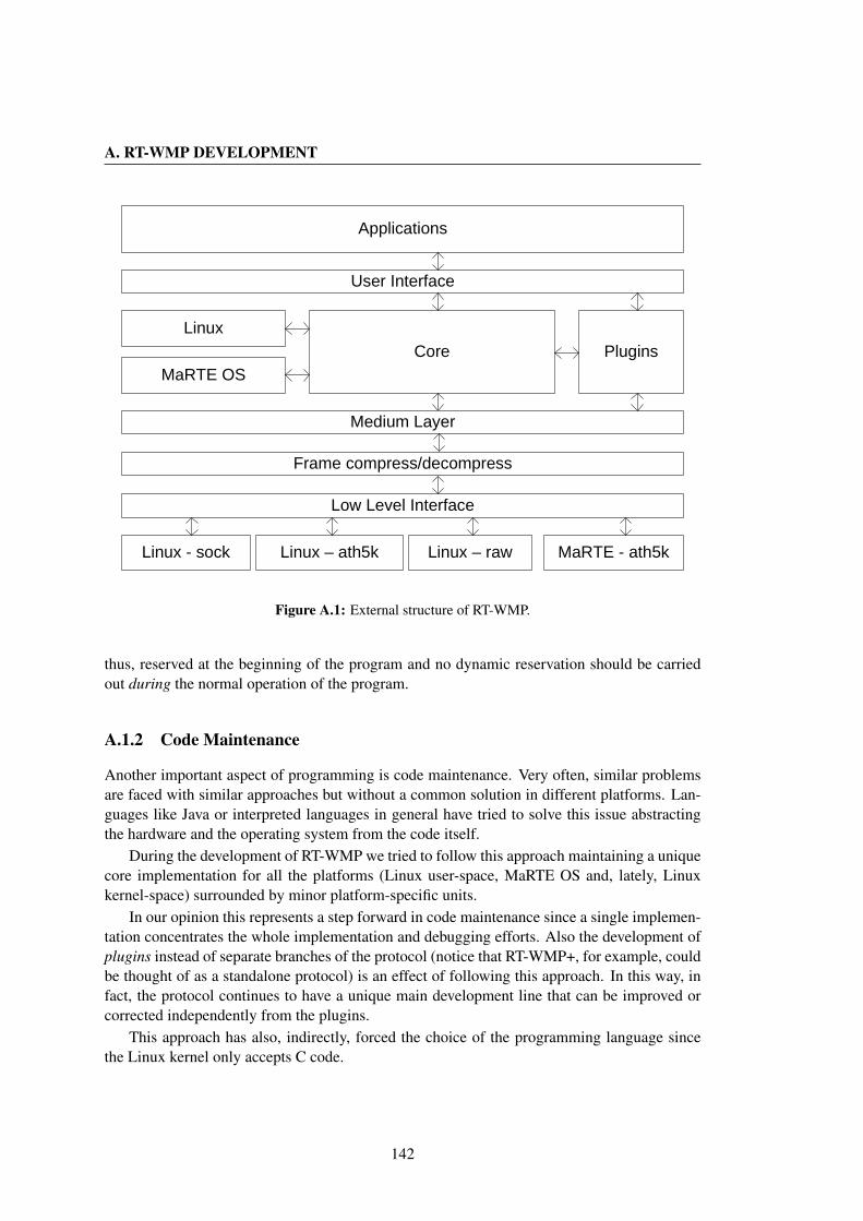
A. RT-WMP DEVELOPMENT
PluginsCore
User Interface
Low Level Interface
MaRTE OS
Applications
Linux
Linux - sock Linux – ath5k Linux – raw MaRTE - ath5k
Frame compress/decompress
Medium Layer
Figure A.1: External structure of RT-WMP.
thus, reserved at the beginning of the program and no dynamic reservation should be carriedout during the normal operation of the program.
A.1.2 Code Maintenance
Another important aspect of programming is code maintenance. Very often, similar problemsare faced with similar approaches but without a common solution in different platforms. Lan-guages like Java or interpreted languages in general have tried to solve this issue abstractingthe hardware and the operating system from the code itself.
During the development of RT-WMP we tried to follow this approach maintaining a uniquecore implementation for all the platforms (Linux user-space, MaRTE OS and, lately, Linuxkernel-space) surrounded by minor platform-specific units.
In our opinion this represents a step forward in code maintenance since a single implemen-tation concentrates the whole implementation and debugging efforts. Also the development ofplugins instead of separate branches of the protocol (notice that RT-WMP+, for example, couldbe thought of as a standalone protocol) is an effect of following this approach. In this way, infact, the protocol continues to have a unique main development line that can be improved orcorrected independently from the plugins.
This approach has also, indirectly, forced the choice of the programming language sincethe Linux kernel only accepts C code.
142
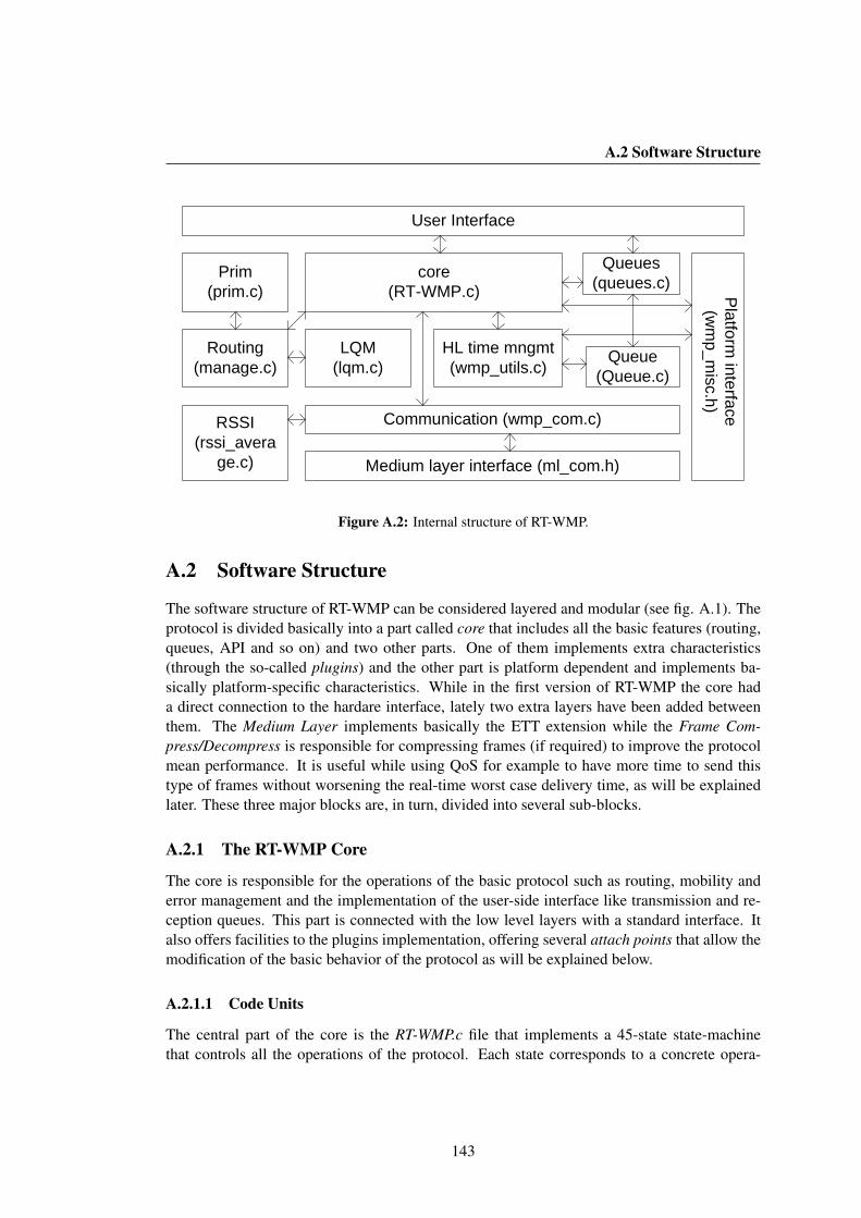
A.2 Software Structure
Queues (queues.c)
LQM (lqm.c)
RSSI(rssi_avera
ge.c)
core (RT-WMP.c)
Communication (wmp_com.c)
Medium layer interface (ml_com.h)
User Interface
Routing (manage.c)
Queue (Queue.c)
Prim(prim.c)
HL time mngmt(wmp_utils.c)
Platform
interface(w
mp_m
isc.h)
Figure A.2: Internal structure of RT-WMP.
A.2 Software Structure
The software structure of RT-WMP can be considered layered and modular (see fig. A.1). Theprotocol is divided basically into a part called core that includes all the basic features (routing,queues, API and so on) and two other parts. One of them implements extra characteristics(through the so-called plugins) and the other part is platform dependent and implements ba-sically platform-specific characteristics. While in the first version of RT-WMP the core hada direct connection to the hardare interface, lately two extra layers have been added betweenthem. The Medium Layer implements basically the ETT extension while the Frame Com-press/Decompress is responsible for compressing frames (if required) to improve the protocolmean performance. It is useful while using QoS for example to have more time to send thistype of frames without worsening the real-time worst case delivery time, as will be explainedlater. These three major blocks are, in turn, divided into several sub-blocks.
A.2.1 The RT-WMP Core
The core is responsible for the operations of the basic protocol such as routing, mobility anderror management and the implementation of the user-side interface like transmission and re-ception queues. This part is connected with the low level layers with a standard interface. Italso offers facilities to the plugins implementation, offering several attach points that allow themodification of the basic behavior of the protocol as will be explained below.
A.2.1.1 Code Units
The central part of the core is the RT-WMP.c file that implements a 45-state state-machinethat controls all the operations of the protocol. Each state corresponds to a concrete opera-
143
A. RT-WMP DEVELOPMENT
tion, like message-queue or dequeue, RSSI update and so on. The same file implements theAPIs for protocol setup, start and stop, both in foreground and background state. A file calledmanage.c manages the routing and all the events that happen during the three phases of theprotocol including error situations. This is the most important unit of the implementation sinceit contemplates all different events that can occur during the operation including error, timeoutexpiration and so on. This part relies, among others, on the wmp com.c unit that is responsi-ble for abstracting the low levels communication layer. This unit offers functions to send andreceive RT-WMP frames. These functions translate the requests to the lower level layers.
The mobility of the nodes is also managed in the core. The lqm.c unit implements theLink Quality Matrix and offers functions to modify, consult or update its elements that are,however, updated after the reception of any frame. The rssi average.c unit manages this event,extracting information about the RSSI from the frame and calculating the mobile average (usingMobileAverage.c) that is then used to actualize the LQM elements. The dijkstra alg.c anddijkstra.c units manage the use of the Dijkstra algorithm within the protocol at the lower andhigher level respectively. The first implements the basic algorithm while the second implementsthe higher level functions that permit knowing the best path, the presence of a concrete node in apath and so on. The prim.c unit is used to calculate (when needed) the Minumum Spanning Treeof the network starting from the information contained in the LQM. The unit queue.c managesthe access to both the reception and transmission queues (implemented in the Queue.c) unit.The access to the queues is possible both from inside the protocol and from the user side (i.e.implements a part of the user interface). Finally the wmp utils.c unit contains high-level time-management functions (low-level ones are platform-dependent).
The core is connected with the rest of the implementation with two interfaces: the mediumlayer interface (ml com.h) and the platform interface wmp misc.h plus a set of attach-pointsused by plugins to modify the protocol behavior (see below). The first interface consists ba-sically of only one send function (ml send) and a receive function (ml receive) by means ofwhich the core sends and receives frames from lower layers. The wmp misc.h is the interfaceto the platform dependent part of the protocol (excluding the low-level communication). At theother side of the interface there is the implementation of time-related or disk access functions(to read configuration files, for example).
A.2.2 Medium Layer
This layer has been recently added to the protocol to manage ETT events in a transparent formand some other behaviors of the protocol. While the ml send function only bypasses the call tothe underlying layer, the ml receive has a slightly more complicated task. The medium layer, infact, receives all the frames from the bottom layer (both RT-WMP and not) and filters the alienones. Moreover, it evaluates the time lost in reception due to the presence of foreign trafficand expands the timeout consequently in a transparent manner (see chap. 7 for details). Thischaracteristic was previously implemented in the lowest communication level but in this wayeach interface had to have its own implementation, increasing the possibility of codificationerror.
144

A.2 Software Structure
A.2.3 Frame Compress/Decompress
To alleviate the problem of overheads, we recently added an extra layer between the mediumand the low level communication layers. This layer is responsible for compressing the wholeRT-WMP frame to reduce the mean protocol overhead. At the moment it uses a gzip compres-sion (zlib library) that is capable of reducing by about 50% the size of the frames on average.The worst-case, however, does not improve since in some situations the compression can in-crease the frame size (there are sets of data that gzip is unable to compress) in which case theframe is sent uncompressed. The worst-case does not worsen either, even if a little computationtime must be taken into account at planning time.
A.2.4 Low Level Communication
Actual reception and transmission is managed by the low-level communication layer. This of-fers to the upper layers uniquely a ll send and ll receive function. To the first of them it isrequired to send the frames while the second must provide to the upper layers all the frames re-ceived within timeout (both protocol and alien ones). Its implementation is platform dependentand partially hardware dependent. Each platform implements, in fact, one or more hardwareinterfaces (hwi).
The linux us Platform
The linux us platform has three different implementations: sock, raw and ath5k. The first usesstandard berkley sockets with UDP and IP protocols. Applications compiled using this hwiare the only ones that do not need superuser privileges to be executed. The raw hwi relieson raw sockets (more direct access to hardware). In this case the ll com.c unit is responsiblefor constructing the frame header (RT-WMP frames travel as encapsulated ethernet in 802.11frames) specifying the 0x6969 protocol identification (PID) (0x6970 for compressed frames).The ath5k hwi relies, however, on a special kernel module called ath5 raw (developed at RoP-ERT) that allows a direct access to hardware guaranteeing a more efficient and less controlledmanagement of the 802.11 frames. It allows us also to know the RSSI of the frames received.This hwi is the preferred choice since it is capable of offering almost real-time behavior evenin a non real-time OS (avoiding the Linux Network Layer).
The MaRTE OS Platform
At present, MaRTE OS only supports two types of wireless network card, those based on theRalink RT61 chipset and those based on the Atheros 5212/52xx chipset. The RT-WMP is capa-ble of using both of them even if the 52xx support is much more complete (the correspondingdriver, brother of ath5k raw for linux, has been developed at RoPERT). The use of MaRTEOS with ath5k raw results in a complete real-time system and is thus the best way to make themost of the RT-WMP real-time characteristics.
145

A. RT-WMP DEVELOPMENT
NEW_TOKEN
WMP_RECEIVE
...
enter_in_state
exit_from_state
next_state
mai
n lo
op
Attach points
Protocol States
ML_RX event
State Function
Figure A.3: Attach Points.
A.2.5 Plugins
One of the most interesting characteristics of the RT-WMP implementations is the so calledplugins. These are pieces of code that modify or alter the behavior of the basic protocol or evenadd functionalities. There are fundamentally three types of plugins (see fig. A.3):
• Extension implementation. Allows modification of the behavior of the basic protocol.Examples are the PME and QoS extension. At the same time implements part of the userinterface like, for example, QoS or multicast queues.
• Functionality addition. Adds new functionality to the basic protocol. Examples aremulti queue (that allows having multiple reception queues) and logger (that allows record-ing locally the received frames to be successively analysed using the wmpSniffer).
• Environment modification. This type of plugins simulates a different environment for thenetwork. Examples are the fake lqm (that allows simulating different network topolo-gies) and fake error (that allows the introduction of fake reception errors or misses).
Some of these act directly on the state machine and modify the succession of events. Asan example, consider the QoS extension. In the basic protocol, after the delivery of a mes-sage, the basic protocol restarts a standard PAP. The machine state moves, thus, from the EN-QUEUE MESSAGE to the NEW TOKEN states. The QoS extension modifies this behaviorintercepting this event and switching, after having prepared the corresponding frame, to theEVALUATE AUTHORIZATION state that provokes the evaluation and the subsequent sendingof the QoS Authorization. To do this, the extensions register their functions to the so calledattach-points. When the execution of the code reaches one attach-point, all the functions regis-tered are called. There are three types of attach-points and a fourth that will be explained later.The first is called enter in state and the registered functions are called before the state machine
146

A.3 API
executes the code associated to that state. In the example above, the QoS registers a functionon the attach point enter in state for the CREATE NEW TOKEN state in order to modify it, af-ter having prepared the corresponding frame, to the EVALUATE AUTHORIZATION state. Thesecond type is called exit from state. In this case the functions are called after the executionof the corresponding state. The third, called next state, is called just after the latter but withthe information about what will be the next state of the state machine. The QoS and multicastextensions use this scheme together with the multi queue plugin.
Other plugins attach to a different type of attach-point called actions. The idea is verysimilar but this time the actions do not correspond to states of the state machines. When theexecution of the code reaches an event attach-point, all the plugins functions registered arecalled. The functions have the possibility of allowing or denying the execution of the codeassociated with the event. As an example, consider the fake error plugin. It registers itself inthe ML RX event that is executed when a protocol frame is correctly received by the mediumlayer. When the fake error function is executed, it has the possibility of denying the pass of theframe to the upper layer provoking a reception error and, probably, a transmission retry.
The fake error and fake lqm use this scheme together with the logger plugins that, however,always allows the execution of the corresponding event.
A.3 API
In this section, the API of the protocol is presented. Functions are often implemented in thecore (especially in the queues.c, RT-WMP.c and inteface.c units). However, some plugins alsohave their own interface. The most important functions, together with those to setup and runthe protocol, are the functions to interact with queues. All these functions work with a Msg datatype that contains information about message priority, source destination and so on. It is definedas in listing A.1. There is a private part where priv t priv is used to manage internally themessage and a two extra fields (in a union) to manage QoS and PME extensions respectively.Due to the reasons explained above, the data field is defined as a constant-size vector. Thecomplete basic interface is defined in listing A.2. It includes functions to setup the protocol(specifying the total number of nodes and WMP address of the local node) and to run theprotocol both in foreground, with the wmpRun() function, or in background with wmpRunBG().Other functions are used to stop the protocol (lines 8 and 9).
The management of the queues is quite complete and straightforward (lines 12− 20). Therest of the functions allow information to be obtained about the protocol operation and setinternal parameters. The names of the functions are quite self-explanatory.
Plugins
The wmpAddPlugin() function accepts a variable-length parameter list function f and is usedto add plugins to the basic protocol. The function f has to register the plugin-related functionto the above-mentioned attach-points.
The multi queue extension adds the functions defined in the listing A.3 to the interface.The multi queue function accepts two parameters: the number and the size of the queues. The
147
A. RT-WMP DEVELOPMENT
rest are similar to the queue-management functions of the basic protocol with the additionof a parameter specifying the number of the queue over which the user wants to execute theoperation. Even if these functions are always compiled together with the protocol, they areonly available for application if the corresponding plugins have been added to the protocol inthe manner explained below.
The PME multicast also extends the global interface with the functions defined in listingA.4. They basically permit access to the multicast queues. Finally, the QoS Extension againprovides functions to access to its particular queues. The functions are listed in the listing A.5.
A.4 Example of Application
The listing A.6 shows an example application of the RT-WMP. The application only sendsmessages (pushing them in the transmission queue) and receives messages from other nodes(popping them from the reception queue).
One transmission and one reception thread are defined. They call the wmpPush() and wmp-Pop() functions respectively. Notice that the latter are both blocking functions. The mainfunction calls the wmpSetup function passing it the id of the node and the number of the net-work nodes. Then the fake lqm plugin is added, specifying the type of network required. Boththreads are launched and finally the protocol is started (in foreground) calling the wmpRun()function (blocking).
148
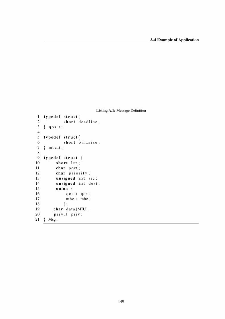
A.4 Example of Application
Listing A.1: Message Definition
1 t y p e d e f s t r u c t {2 s h o r t d e a d l i n e ;3 } q o s t ;45 t y p e d e f s t r u c t {6 s h o r t b i n s i z e ;7 } mbc t ;89 t y p e d e f s t r u c t {
10 s h o r t l e n ;11 char p o r t ;12 char p r i o r i t y ;13 unsigned i n t s r c ;14 unsigned i n t d e s t ;15 union {16 q o s t qos ;17 mbc t mbc ;18 } ;19 char d a t a [MTU] ;20 p r i v t p r i v ;21 } Msg ;
149
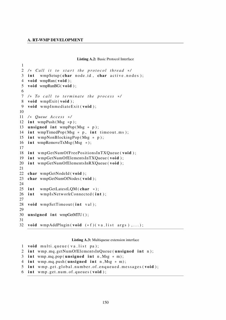
A. RT-WMP DEVELOPMENT
Listing A.2: Basic Protocol Interface
12 /∗ C a l l i t t o s t a r t t h e p r o t o c o l t h r e a d ∗ /3 i n t wmpSetup ( char node id , char a c t i v e n o d e s ) ;4 void wmpRun( void ) ;5 void wmpRunBG( void ) ;67 /∗ To c a l l t o t e r m i n a t e t h e p r o c e s s ∗ /8 void wmpExit ( void ) ;9 void wmpInmedia teExi t ( void ) ;
1011 /∗ Queue Ac ce s s ∗ /12 i n t wmpPush ( Msg ∗p ) ;13 unsigned i n t wmpPop ( Msg ∗ p ) ;14 i n t wmpTimedPop ( Msg ∗ p , i n t t i m e o u t m s ) ;15 i n t wmpNonBlockingPop ( Msg ∗ p ) ;16 i n t wmpRemoveTxMsg ( Msg ∗ ) ;1718 i n t wmpGetNumOfFreePosit ionsInTXQueue ( void ) ;19 i n t wmpGetNumOfElementsInTXQueue ( void ) ;20 i n t wmpGetNumOfElementsInRXQueue ( void ) ;2122 char wmpGetNodeId ( void ) ;23 char wmpGetNumOfNodes ( void ) ;2425 i n t wmpGetLatestLQM ( char ∗ ) ;26 i n t wmpIsNetworkConnected ( i n t ) ;2728 void wmpSetTimeout ( i n t v a l ) ;2930 unsigned i n t wmpGetMTU ( ) ;3132 void wmpAddPlugin ( void (∗ f ) ( v a l i s t a r g s ) , . . . ) ;
Listing A.3: Multiqueue extension interface
1 void m u l t i q u e u e ( v a l i s t pa ) ;2 i n t wmp mq getNumOfElementsInQueue ( unsigned i n t n ) ;3 i n t wmp mq pop ( unsigned i n t n , Msg ∗ m) ;4 i n t wmp mq push ( unsigned i n t n , Msg ∗ m) ;5 i n t w m p g e t g l o b a l n u m b e r o f e n q u e u e d m e s s a g e s ( void ) ;6 i n t wmp get num of queues ( void ) ;
150

A.4 Example of Application
Listing A.4: PME multicast extension interface
1 i n t wmpPushBC ( Msg ∗p ) ;2 i n t wmpPopBC( Msg ∗p ) ;3 i n t wmpGetNumOfElementsInRXBCQueue ( void ) ;4 i n t wmpGetNumOfElementsInTXBCQueue ( void ) ;5 i n t wmpGetNumOfFreePositionsInTXBCQueue ( void ) ;6 i n t wmpGetNumOfFreePositionsInRXBCQueue ( void ) ;
Listing A.5: QoS extension interface
1 void wmpPushQoS ( Msg ∗p ) ;2 i n t wmpPopQoS ( Msg ∗p ) ;
151
A. RT-WMP DEVELOPMENT
Listing A.6: Example application
1 # i n c l u d e < . . .>2 # i n c l u d e ” p l u g i n s / f a k e l q m / f a k e l q m . h ”34 void ∗ f t h r e a d t x ( void ∗ param ){5 whi le ( 1 ){6 Msg m;7 m. p r i o r i t y = rand ( ) % 100 ;8 m. s r c = wmpGetNodeId ( ) ;9 m. d e s t = m. s r c ;
10 whi le (m. d e s t == m. s r c ){11 m. d e s t = rand ( ) % wmpGetNumOfNodes ( ) ;12 }13 s p r i n t f (m. da t a , ” Message ” ) ;14 m. l e n = s t r l e n (m. d a t a ) ;15 wmpPush(&m) ;16 mss l eep ( 1 0 0 ) ;17 }18 }1920 void ∗ f t h r e a d r x ( void ∗ param ){21 whi le ( 1 ){22 Msg m;23 wmpPop(&m) ;24 }25 }2627 i n t main ( i n t argc , char∗ a rgv [ ] ) {28 p t h r e a d t th1 , t h 2 ;29 i f ( a r g c < 3){30 e x i t ( 0 ) ;31 }32 wmpSetup ( a t o i ( a rgv [ 1 ] ) , a t o i ( a rgv [ 2 ] ) ;33 wmpAddPlugin ( fake lqm , STRING ) ;34 wmpSetTimeout ( 5 ) ;35 p t h r e a d c r e a t e (& th2 , 0 , f t h r e a d t x , 0 ) ;36 p t h r e a d c r e a t e (& th1 , 0 , f t h r e a d r x , 0 ) ;37 wmpRun ( ) ;38 }
152
Appendix B
Field Experiments
Many tests and experiments have been done to verify the effectiveness and debug the protocoland its extensions during the development stage. Moreover, numerous tests have been donewithin the framework of specific applications like those described throughout the text and in-troduced in this chapter.
The first tests were made at the beginning of 2006 and the last just a few days ago. Thisappendix summarises some of the experiments conducted in real scenarios such as tunnels, carparks etc.
The experiments belong to different applications and scenarios. An initial catalogue is asfollows:
• Robot underground communication. The objective of this type of experiment was tomaintain connected a team of robots with a base station in an underground environment.The experiment involved several tasks including localization, manipulation, real-timeand, lately, QoS communication.
• Surveillance. In this case the team of robots had to search a car park to locate a carof a specific color and registration number. These experiments involved tasks includingvision, localization and, of course, real-time communication for cooperative perceptionand to transmit photos and results to the base station.
• Network connectivity. These experiments were carried out in the context of the applica-tion described in chapter 6. Again they involved real-time communications for kinematicdata sharing.
• Cooperative Navigation and Localization. Several experiments were carried out toevaluate cooperative navigation and localization techniques developed at RoPERT. Inthese experiments, real-time multicast communication played an important role in thedata sharing.
• Multimedia communication in underground environments. A large set of experi-ments was carried out to evaluate the effectiveness of the QoS extension of the protocoland with the objective of offering multimedia traffic support in underground and tunnelenvironments.
153

B. FIELD EXPERIMENTS
Table B.1: Chronological list of experiments.
Date Type LocationApril, 7, 2006 Robots in Underground Manzanera TunnelApril, 16, 2006 Robots in Underground Manzanera TunnelJuly, 7, 2006 Robots in Underground Manzanera TunnelApril, 18, 2007 Surveillance CPS Car parkNovember 5, 2007 Network Connectivity CPS Car parkNovember 6, 2007 Network Connectivity CPS Car parkNovember 20, 2007 Network Connectivity CPS Car parkNovember 22, 2007 Network Connectivity CPS Car parkJanuary, 18, 2008 Surveillance CPS Car parkJanuary, 20-27, 2008 Cooperative Navigation CPS BuildingMay, 9, 2008 Multimedia in Underground Somport TunnelSeptember, 2, 2008 Network Connectivity CPS Car parkFebruary, 10, 2009 Network Connectivity CPS BuildingFebruary, 27, 2009 Robots in Underground Somport TunnelDecember, 12-18 Cooperative Navigation CPS BuildingJanuary, 19-23 Cooperative Navigation CPS BuildingMarch, 13, 2009 Multimedia in Underground Somport TunnelMarch, 27, 2009 Robots in Underground Somport TunnelMay, 22, 2009 Multimedia in Underground Somport TunnelAugust, 23, 2009 Multimedia in Underground Somport TunnelSeptember, 3-15, 2009 Cooperative Localization CPS BuildingSeptember, 20, 2009 Multimedia in Underground Somport TunnelOctober, 26, 2009 Multimedia in Underground Somport TunnelNovember 14-20, 2009 Cooperative Navigation UPC, BarcelonaJanuary, 25, 2010 Multimedia in Underground Somport Tunnel
The rest of the chapter offers a selective overview of the experiments with some interestingdata and results. Table B.1 shows a chronological list of several of the experiments carried outduring the long life of the protocol. In the following section, the experiments are explainedwith some additional details.
B.1 Robots Cooperation in Underground Environments
The goal of this type of experiment was to prepare a team of robots to be able to access a dis-aster or inaccessible area almost autonomously. The majority of the experiments were carriedout in tunnels (Manzanera or Somport). In this type of experiment, a set of 3 or 4 robots areautonomously deployed along the tunnel to reach a specified zone (the exit of the tunnel or a a
154

B.1 Robots Cooperation in Underground Environments
lateral gallery). The navigation is cooperative and data are exchanged using the RT-WMP pro-tocol. The farthest robot maintains connectivity with a base station (a laptop) at all times usingthe other robots as relays. During the deployment, a relay node stops when the link-qualitywith its predecessor falls below a fixed threshold. When the lead robot reaches the goal point,it collects some type of information (images or laser data) and sends it to the base station usingthe RT-WMP. The lead robots can be moved remotely using a joystick (telemanipulation) to ex-plore the zone. Also, joystick commands travel as real-time messages. In later experiments, thesupport for voice was added to allow communication between suspected victims present in thedisaster area and the base station. The following sections describe some concrete experimentsof this type.
B.1.1 Manzanera Tunnel, April, 7, 2006
This first test (see fig. B.1) was made to test one of the first versions of the RT-WMP imple-mented over the Windows operating system. The goal was to deploy an autonomous chain ofrobots in the 600 m long Manzanera tunnel able to go out of the opposite end of the tunnel andtake some webcam shots. The robots were supervised through a graphical interface by a basestation.
Figure B.1: First test at Manzanera tunnel.
The experiment was not successful. The robots had problems moving and communicationsthat worked well indoors were less successful in the tunnel. However, we learned many lessonsfrom this first experiment enabling us to experience better luck in the subsequent test.
B.1.2 Manzanera Tunnel, April, 16, 2006
The second test (see fig. B.2) attempted the same goal as the first, this time successfully. Oneof the robots exited the tunnel and took some photos from the outside.
Even if the test was considered successful, neither the system nor the protocol could beconsidered totally real-time due to the operating system used and the early stage of developmentof the RT-WMP.
155
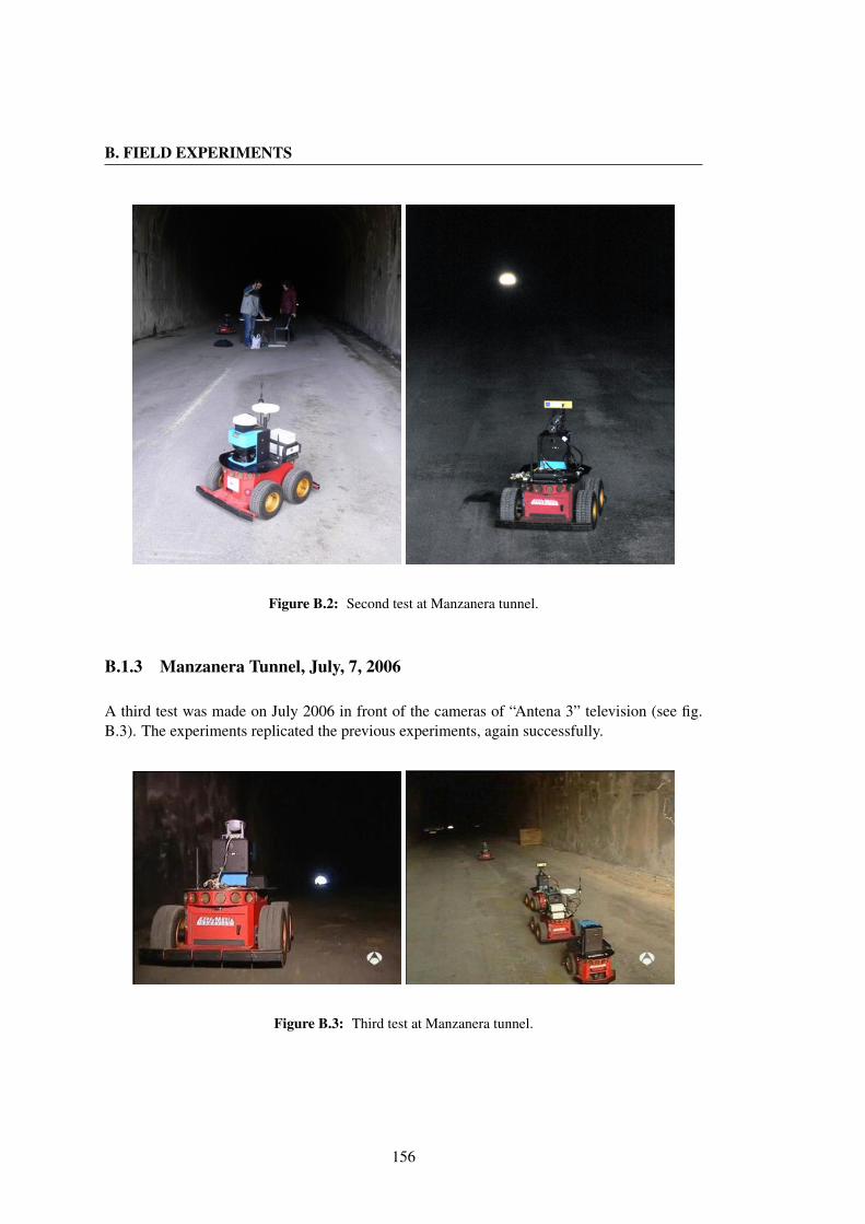
B. FIELD EXPERIMENTS
Figure B.2: Second test at Manzanera tunnel.
B.1.3 Manzanera Tunnel, July, 7, 2006
A third test was made on July 2006 in front of the cameras of “Antena 3” television (see fig.B.3). The experiments replicated the previous experiments, again successfully.
Figure B.3: Third test at Manzanera tunnel.
156

B.1 Robots Cooperation in Underground Environments
B.1.4 Canfranc Tunnel, February, 27, 2009
In these experiments we went back to work with robots after a substantial time period hadelapsed. This time we started to prepare a complex experiment that involved autonomous navi-gation, telemanipulation (using RT-WMP) and voice communication (using the QoS extensionfor the first time in a real hostile environment). The preparation relied most of all on au-tonomous navigation. The robots had to navigate following each other while analysing the linkquality among them to stop and act as relays if the connection went below a certain threshold.
Figure B.4: First test at Somport Tunnel.
The experiment was not completely successful since many mechanical problems forced usto remove one robot from the team (see fig. B.4).
B.1.5 Canfranc Tunnel, March, 27, 2009
At the end of March 2009 we performed the most important experiment with robots up to thatpoint. The goal of the experiment was to reach with one of the robots one of the lateral galleriesof the tunnel, enter a refuge and take some photos of the environment while establishing a voicecommunication between the base station (a laptop at the tunnel entrance) and the farthest robot(see fig. B.5). To guarantee wireless connection between the head and the base station, twoadditional robots acted as relays along the tunnel and a third just at the intersection between thetunnel and the lateral gallery. The robots reached this configuration in an autonomous mannersharing relative localization and link quality information by means of the RT-WMP protocol.When the head robot reached the lateral gallery, a user with the laptop started to telemanipulateit to obtain photos of the environment (that could be seen on the laptop screen). At the sametime a voice link was established between both nodes. The voice quality was not very goodand some strange behavior of the QoS extension was identified as well. The robots returnedautonomously. The experiment was considered quite successful. Subsequent analysis of thelogs by means of the wmpSniffer (see chapter 8) enabled us to identify the problem sufferedby the QoS due to a bug in the implementation.
During the same experiment a second team continued the propagation study measuring theRSSI along 3.2 Km of the tunnel. A node was emitting continuously at a certain point of the
157

B. FIELD EXPERIMENTS
tunnel and two laptops were used to record the measured RSSI every 25 m. The graph of themeasurement showed that, as expected, the RSSI is a function of the distance but also thatmany propagation effects (multipath, reflection, etc.) influence its value, especially in relationto the lateral galleries.
Figure B.5: Experiments at Canfranc tunnel.
B.1.6 Canfranc Tunnel, May, 22, 2009
The experiment was repeated, this time without problems and with an excellent voice quality,in May of the same year in the presence of the Spanish Guardia Civil, who were interested inthis application (see fig. B.6).
Figure B.6: Experiments at Canfranc tunnel on May 2009.
B.2 Multimedia in Confined Environments
The objective of these experiments was to offer multimedia traffic support (especially voice) tomobile nodes in confined environments. This is especially useful in situations in which othermethods such as leaky feeders or infrastructure networks are unavailable or too expensive (fortunnels under construction, disaster areas, mines, etc.). The idea is to deploy a set of easy-to-setup backbone nodes in the confined environment. Two or more mobile nodes use these nodesas relays to establish a voice communication among them. The RT-WMP and its QoS extensionis used as a transport protocol guaranteeing the possibility of establishing simultaneous real-time flows and native mobility management. The experiments were carried out mainly in the
158
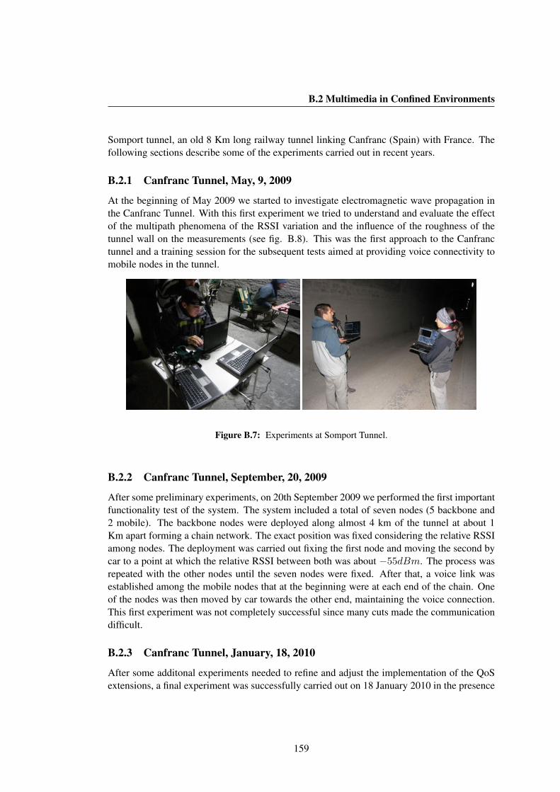
B.2 Multimedia in Confined Environments
Somport tunnel, an old 8 Km long railway tunnel linking Canfranc (Spain) with France. Thefollowing sections describe some of the experiments carried out in recent years.
B.2.1 Canfranc Tunnel, May, 9, 2009
At the beginning of May 2009 we started to investigate electromagnetic wave propagation inthe Canfranc Tunnel. With this first experiment we tried to understand and evaluate the effectof the multipath phenomena of the RSSI variation and the influence of the roughness of thetunnel wall on the measurements (see fig. B.8). This was the first approach to the Canfranctunnel and a training session for the subsequent tests aimed at providing voice connectivity tomobile nodes in the tunnel.
Figure B.7: Experiments at Somport Tunnel.
B.2.2 Canfranc Tunnel, September, 20, 2009
After some preliminary experiments, on 20th September 2009 we performed the first importantfunctionality test of the system. The system included a total of seven nodes (5 backbone and2 mobile). The backbone nodes were deployed along almost 4 km of the tunnel at about 1Km apart forming a chain network. The exact position was fixed considering the relative RSSIamong nodes. The deployment was carried out fixing the first node and moving the second bycar to a point at which the relative RSSI between both was about −55dBm. The process wasrepeated with the other nodes until the seven nodes were fixed. After that, a voice link wasestablished among the mobile nodes that at the beginning were at each end of the chain. Oneof the nodes was then moved by car towards the other end, maintaining the voice connection.This first experiment was not completely successful since many cuts made the communicationdifficult.
B.2.3 Canfranc Tunnel, January, 18, 2010
After some additonal experiments needed to refine and adjust the implementation of the QoSextensions, a final experiment was successfully carried out on 18 January 2010 in the presence
159
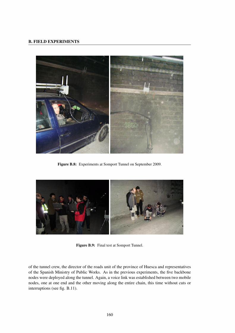
B. FIELD EXPERIMENTS
Figure B.8: Experiments at Somport Tunnel on September 2009.
Figure B.9: Final test at Somport Tunnel.
of the tunnel crew, the director of the roads unit of the province of Huesca and representativesof the Spanish Ministry of Public Works. As in the previous experiments, the five backbonenodes were deployed along the tunnel. Again, a voice link was established between two mobilenodes, one at one end and the other moving along the entire chain, this time without cuts orinterruptions (see fig. B.11).
160

B.3 Surveillance
Figure B.10: Surveillance experiments at CPS car park.
B.3 Surveillance
These experiments had the objective of creating a complete framework for surveillance tasks.The experiment scenario was a car park. The goal was to explore the whole car park withdifferent robots to locate and identify a red car with a particular numberplate. The experimentsinvolved several tasks including navigation, computer vision (with omnidirectional camera),task allocation (to distribute the work to robots in an optimal manner) and real-time commu-nication for synchronization and decision making. In these experiments each robot coveredone or more lanes of the car park and stopped when it found a red car. It then took a photo ofthe numberplate and through a plate recognition software identified the car and sent the imageand the result of the recognition to a base station using multi-hop real-time communication(RT-WMP) (see fig. B.10).
Several experiments were carried out in the CPS car park. The final test was performed on18 January 2008 with satisfactory results.
B.4 Network connectivity
The development of a complete framework for network connectivity enforcement (describedin chapter 6) motivated a large set of experiments in real scenarios. Almost all the experimentswere carried out in the CPS car park between November 2007 and September 2008. A lastexperiment was performed in February 2009 in the CPS building. The final experiments aredescribed in section 6.7.
B.5 Cooperative Navigation and Localization
Cooperation among robots often requires data sharing among the team members. The coopera-tive navigation technique developed between 2008 and 2009 at RoPERT relies on the multicastcapability of RT-WMP. This motivated several experiments related with the protocol and helpedtowards the improvement of such a multicast extension in the same way as the experiments car-ried out during the URUS project. This technique allows formation movement of robots butrequires the sharing of kinematic data among the members of the team that would not be pos-
161
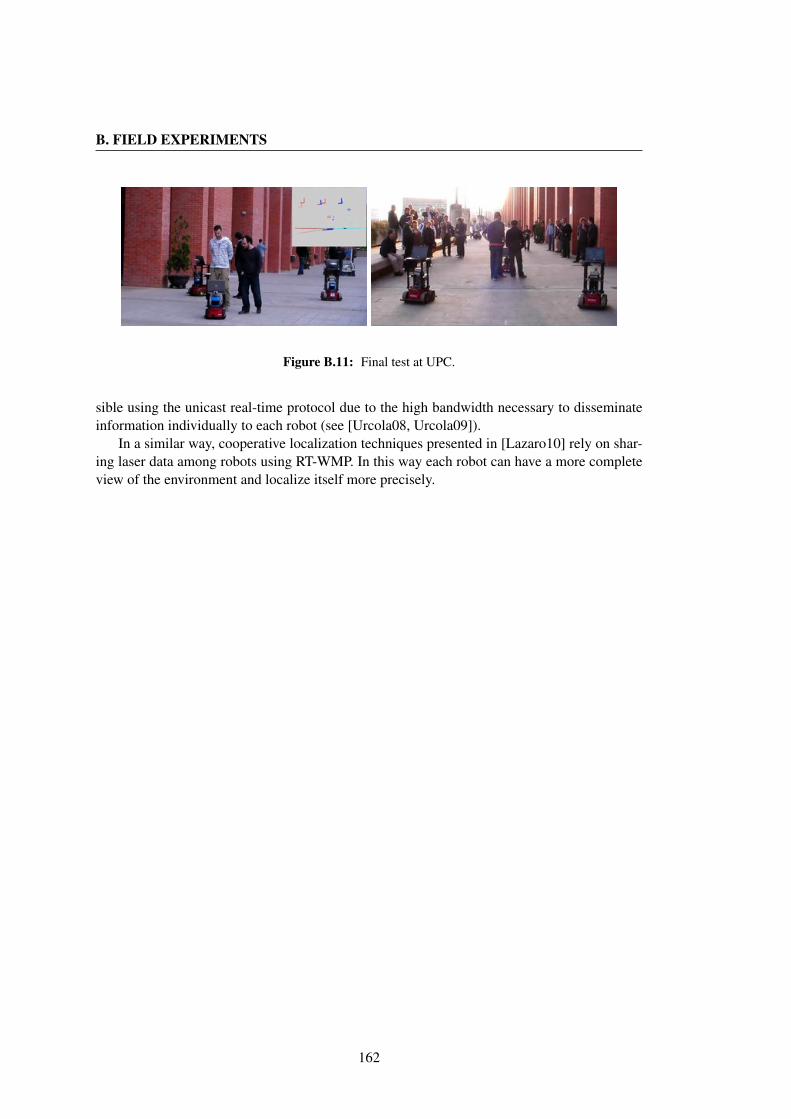
B. FIELD EXPERIMENTS
Figure B.11: Final test at UPC.
sible using the unicast real-time protocol due to the high bandwidth necessary to disseminateinformation individually to each robot (see [Urcola08, Urcola09]).
In a similar way, cooperative localization techniques presented in [Lazaro10] rely on shar-ing laser data among robots using RT-WMP. In this way each robot can have a more completeview of the environment and localize itself more precisely.
162
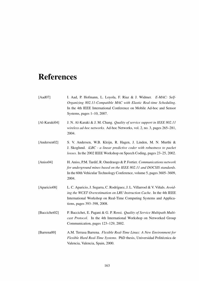
References
[Aad07] I. Aad, P. Hofmann, L. Loyola, F. Riaz & J. Widmer. E-MAC: Self-Organizing 802.11-Compatible MAC with Elastic Real-time Scheduling.In the 4th IEEE International Conference on Mobile Ad-hoc and SensorSystems, pages 1–10, 2007.
[Al-Karaki04] J. N. Al-Karaki & J. M. Chang. Quality of service support in IEEE 802.11wireless ad-hoc networks. Ad-hoc Networks, vol. 2, no. 3, pages 265–281,2004.
[Andersen02] S. V. Andersen, W.B. Kleijn, R. Hagen, J. Linden, M. N. Murthi &J. Skoglund. iLBC - a linear predictive coder with robustness to packetlosses. In the 2002 IEEE Workshop on Speech Coding, pages 23–25, 2002.
[Aniss04] H. Aniss, P.M. Tardif, R. Ouedraogo & P. Fortier. Communications networkfor underground mines based on the IEEE 802.11 and DOCSIS standards.In the 60th Vehicular Technology Conference, volume 5, pages 3605–3609,2004.
[Aparicio08] L. C. Aparicio, J. Segarra, C. Rodrıguez, J. L. Villarroel & V. Vinals. Avoid-ing the WCET Overestimation on LRU Instruction Cache. In the 4th IEEEInternational Workshop on Real-Time Computing Systems and Applica-tions, pages 393–398, 2008.
[Baccichet02] P. Baccichet, E. Pagani & G. P. Rossi. Quality of Service Multipath Multi-cast Protocol. In the 4th International Workshop on Networked GroupCommunication, pages 123–129, 2002.
[Barrena00] A.M. Terrasa Barrena. Flexible Real-Time Linux: A New Environment forFlexible Hard Real-Time Systems. PhD thesis, Universidad Politecnica deValencia, Valencia, Spain, 2000.
163

REFERENCES
[Basu04] P. Basu & J. Redi. Movement Control Algorithms for Realization of FaultTolerant Ad-hoc Robot Networks. IEEE Network, vol. 18, no. 4, pages36–44, July 2004.
[Beaudoin04] J. J. Beaudoin, G. Tran, P. M. Tardif & P. Fortier. Underground experi-ments of video transmission over an IEEE 802.11 infrastructure. In the60th IEEE Vehicular Technology Conference, volume 5, pages 3610–3614Vol. 5, 2004.
[Benzakour04] A. Benzakour, S. Affes, C. Despins & P.M. Tardif. Wideband measure-ments of channel characteristics at 2.4 and 5.8 GHz in underground min-ing environments. In the 60th IEEE Vehicular Technology Conference,volume 5, pages 3595–3599, 2004.
[BLUETOOTH] Bluetooth web site: http://www.bluetooth.com.
[Burgard05] W. Burgard, M. Moors, C. Stachniss & F. Schneider. Coordinated Multi-Robot Exploration. IEEE Transactions on Robotics, vol. 21, no. 3, pages376–378, 2005.
[Chou04] C. T. Chou & K. G. Shin. Analysis of Adaptive Bandwidth Allocation inWireless Networks with Multilevel Degradable Quality of Service. IEEETransactions on Mobile Computing, vol. 3, no. 1, pages 5–17, 2004.
[Damian00] D. E. Herlea Damian, M. L. G. Shaw & B. R. Gaines. Token-Passing BusAccess Method and Physical Layer Specifications. IEEE Standard 802.4-1985, vol. 238, 2000.
[DARPA07] DARPA Landroids to autonomously cover areas with Wi-Fi, 2007.
[Dijkstra59] E. W. Dijkstra. A Note on Two Problems in Connexion with Graphs. Nu-merische Mathematik, vol. 1, pages 269–271, 1959.
[Donatiello03] L. Donatiello & M. Furini. Ad-hoc Networks: A Protocol for SupportingQoS Applications. In the 17th IEEE International Symposium on Paralleland Distributed Processing, pages 219–222, 2003.
[Dudley07] D. G. Dudley, M. Lienard, S. F. Mahmoud & P. Degauque. Wireless prop-agation in tunnels. IEEE Antennas and Propagation Magazine, vol. 49,no. 2, pages 11–26, 2007.
164
REFERENCES
[Ergen03] M. Ergen, D. Lee, R. Sengupta & P. Varaiya. Wireless token ring protocol-performance comparison with IEEE 802.11. In the 8th IEEE InternationalSymposium on Computers and Communication, volume 2, pages 710–715,2003.
[Fabregat04] R. Fabregat, Y. Donoso, J. L. Marzo & A. Ariza. Multi-Objective Mul-tipath Routing Algorithm for Multicast Flows. In the 2004 InternationalSymposium on Performance Evaluation of Computer and Telecommunica-tion Systems, 2004.
[Facchinetti05a] T. Facchinetti, G. Buttazzo & L. Almeida. Dynamic resource reservationand connectivity tracking to support real-time communication among mo-bile units. EURASIP Journal on Wireless Communication and Networking,vol. 5, no. 5, pages 712–730, 2005.
[Facchinetti05b] T. Facchinetti, G. Buttazzo & L. Almeida. A Flexible Visual Simulator forWireless Ad-Hoc Networks of Mobile Nodes. In the 10th IEEE InternationalConference on Emerging Technologies and Factory Automation, 2005.
[Facchinetti08] T. Facchinetti, G. Franchino & G. Buttazzo. A Distributed CoordinationProtocol for the Connectivity Maintenance in a Network of Mobile Units. Inthe 2008 international Conference on Advances in Mesh Networks, pages764–769, 2008.
[Farkas08] K. Farkas, T. Hossmann, F. Legendre, B. Plattner & S.K. Das. Link QualityPrediction in Mesh Networks. Computer Comunications, vol. 31, pages1497–1512, 2008.
[FIP] FIP web site: http://www.worldfip.org/.
[Franchino10] G. Franchino, G. Buttazzo & T. Facchinetti. Factory Automation, chapterToken Passing Techniques for Hard Real-Time Communication. IN-TECH,2010.
[FRTOS] FreeRTOS web site: http://www.freertos.org/.
[Gerkey03] B.P. Gerkey, R.T. Vaughan & A. Howard. The Player/Stage Project: Toolsfor Multi-Robot and Distributed Sensor Systems. In the 2003 InternationalConference on Advanced Robotics, pages 317–323, 2003.
165
REFERENCES
[Gerkey04] B. P. Gerkey & M. J. Mataric. A formal analysis and taxonomy of task allo-cation in multi-robot systems. International Journal of Robotics Research,vol. 23, no. 9, pages 939–954, Sep. 2004.
[Gulec05] N. Gulec & M. Unel. A Novel Coordination Scheme Applied to Nonholo-nomic Mobile Robots. In the 44th IEEE Conference on Decision and Con-trol, pages 5089–5094, 2005.
[Hamidian07] A. Hamidian & U. Korner. Providing QoS in Ad-hoc Networks withDistributed Resource Reservation. In the 20th International TeletrafficCongress, pages 309–320, 2007.
[Hanssen03] F. Hanssen & P. G. Jansen. Real-time communication protocols: anoverview. Technical report, University of Twente in the Netherlands, 2003.
[Harbour01] M. Gonzalez Harbour, J.J. Gutierrez Garcia, J.C. Palencia Gutierrez &J.M. Drake Moyano. MAST: Modeling and Analysis Suite for Real TimeApplications. In the 13th IEEE Euromicro Conference on Real-Time Sys-tems, pages 1–25, 2001.
[IEEE97] IEEE 802.11-1997 Standard, Part 11: Wireless LAN Medium Access Con-trol (MAC) and Physical Layer (PHY) Specifications. IEEE ComputerSo-ciety LAN MAN Stradards Committee, 1997.
[IEEE03a] IEEE 802.15.3-2003 Standard, Part 15.3: Wireless medium access con-trol (MAC) and physical layer (PHY) specifications for higher rate wire-less personal area networks (WPAN). IEEE Computer Society LAN MANStradards Committee, 2003.
[IEEE03b] IEEE 802.15.4-2003 Standard, Part 15.4: Wireless medium access control(MAC) and physical layer (PHY) specifications for Low-Rate Wireless Per-sonal Area Networks (LR-WPANs). IEEE Computer Sogciety LAN MANStradards Committee, 2003.
[IEEE05] IEEE 802.11e-2005 Standard, Part 11e: Wireless LAN Medium AccessControl (MAC) and Physical Layer (PHY) specifications, Amendment 8:Medium Access Control (MAC) Quality of Service Enhancements. IEEEComputer Society LAN MAN Stradards Committee, 2005.
166

REFERENCES
[ISO93] Road Vehicles - Interchange of Digital Information - Controller Area Net-work (CAN) for High-Speed Communication. International Standards Or-ganisation, 1993.
[ITU03] ITU. One-way transmission time. In ITU-T Recommendation G.114, May2003.
[Jia96] X. Jia, J. Cao & W. Jia. Real-time multicast routing with optimal networkcost. In the 3rd IEEE International Workshop on Real-Time ComputingSystems Application, page 49, 1996.
[Jun03] J. Jun, P. Peddabachagari & M. Sichitiu. Theoretical Maximum Through-put of IEEE 802.11 and its Applications. In the 2nd IEEE InternationalSymposium on Network Computing and Applications, page 249, 2003.
[Kalra07] N. Kalra, D. Ferguson & A. Stentz. A Generalized Framework for SolvingTightly-coupled Multirobot Planning Problems. In the 2007 IEEE Interna-tional Conference on Robotics and Automation, pages 3359–3364, 2007.
[Kapp02] S. Kapp. 802.11: Leaving the Wire Behind. IEEE Internet Computing,vol. 6, no. 1, pages 82–85, Jan./Feb. 2002.
[Kopetz89] H. Kopetz, A. Damm, C. Koza, M. Mulazzani, W. Schwabl, C. Senft &R. Zainlinger. Distributed fault-tolerant real-time systems: the Mars ap-proach. IEEE Micro, vol. 9, pages 25–40, Feb. 1989.
[Kuhn55] H. W. Kuhn. The Hungarian Method for the assignment problem. NavalResearch Logistic Quarterly, vol. 2, no. 1, pages 83–97, 1955.
[Lamport78] L. Lamport. Time, clocks, and the ordering of events in a distributed system.Communications of the ACM, vol. 21, no. 7, pages 558–565, July 1978.
[Lazaro10] M. T. Lazaro & J. A. Castellanos. Localization of Probabilistic Robot For-mations in SLAM. In the 2010 IEEE International Conference on Roboticsand Automation, pages 3179–3184, 2010.
[Le Lann93] G. Le Lann & N. Rivire. Real-time communications over broadcast net-works: the CSMA-DCR and the DOD-CSMA-CD protocols. Technical re-port, INRIA, 1993.
167
REFERENCES
[Lee02] D. Lee, R. Attias, A. Puri, R. Sengupta, S. Tripakis & P. Varaiya. A Wire-less Token Ring Protocol For Ad-Hoc Networks. In the 2002 AerospaceConference, 2002.
[Lienard00] M. Lienard & P. Degauque. Natural wave propagation in mine environ-ments. IEEE Transactions on Antennas and Propagation, vol. 48, no. 9,pages 1326–1339, Sep. 2000.
[Lin97] C.R. Lin & M. Gerla. MACA/PR: An asynchronous multimedia multihopwireless network. In Proceedings of the IEEE INFOCOM, 1997.
[Liu00] J. W. S. Liu. Real Time Systems. Prentice Hall PTR, 2000.
[Majumda02] A. Majumda, D. G. Sachs, I. V. Kozintsev, K. Ramchandran & M. M. Ye-ung. Multicast and unicast real-time video streaming over wireless LANs.IEEE Transactions on Circuits and Systems for Video Technology, vol. 12,no. 6, pages 524–534, Jun. 2002.
[Malcolm94] N. Malcolm & W. Zhao. The Timed-Token Protocol for Real-Time Com-munications. Computer, vol. 27, no. 1, pages 35–41, Jan. 1994.
[Malcolm95] N. Malcolm & W. Zhao. Hard real-time communication in multiple-accessnetworks. Real-Time Systems, vol. 8, no. 1, pages 35–77, 1995.
[Mangold02] S. Mangold, S. Choi, P. May, O. Klein, G. Hiertz & L. Stibor. IEEE 802.11eWireless LAN for Quality of Service. In the European Wireless, pages 32–39, 2002.
[Mao06] S. Mao, D. Bushmitch, S. Narayanan & S. S. Panwar. MRTP: A multi-flowreal-time transport protocol for ad-hoc networks. IEEE Transactions onMultimedia, vol. 8, no. 2, pages 356–369, Apr. 2006.
[Martınez05] J. M. Martınez & M. Gonzalez Harbour. RT-EP: A Fixed-Priority RealTime Communication Protocol over Standard Ethernet. In the 10th In-ternational Conference on Reliable Software Technologies, Ada-Europe,pages 180–195, 2005.
[Molle85] M. Molle & L. Kleinrock. Virtual time CSMA: Why two clocks are betterthan one. IEEE Transaction Commununication, vol. 33, pages 919–933,Sep. 1985.
168
REFERENCES
[Moraes08] R. Moraes, F. Vasques & P. Portugal. A TDMA-based mechanism to enforcereal-time behavior in WiFi networks. In the 7th IEEE International Work-shop on Factory Communication Systems, pages 109–112, May 2008.
[Mosteo07a] A. Mosteo, D. Tardioli, L. Riazuelo, J. L. Villarroel & L. Montano. Taskallocation for NRS with enforced connectivity by cooperative navigation.In the Workshop on Network Robot Systems: Ubiquitous, Cooperative,Interactive Robots for Human Robot Symbiosis, 2007.
[Mosteo07b] A. R. Mosteo & L. Montano. Comparative experiments on optimizationcriteria and algorithms for auction based multi-robot task allocation. In the2007 IEEE International Conference on Robotics and Automation, pages3345–3350, 2007.
[Mosteo08] A. R. Mosteo, L. Montano & M.G. Lagoudakis. Multi-Robot Routing underLimited Communication Range. In the 2008 IEEE International Conferenceon Robotics and Automation, pages 1531–1536, 2008.
[Mosteo09] A. R. Mosteo, L. Montano & M.G. Lagoudakis. Guaranteed-PerformanceMulti-Robot Routing under Limited Communication Range. In DistributedAutonomous Robotic Systems, volume 8, pages 491–502. Springer BerlinHeidelberg, 2009.
[Moutairou06] M. Moutairou, H. Aniss & G. Y. Delisle. Wireless mesh access point rout-ing for efficient communication in underground mine. In the 2006 IEEEAntennas and Propagation Society International Symposium, pages 577–580, 2006.
[Nerguizian05] C. Nerguizian, C. L. Despins, S. Affes & M. Djadel. Radio-channel char-acterization of an underground mine at 2.4 GHz. IEEE Transactions onWireless Communications, vol. 4, no. 5, pages 2441–2453, Sep. 2005.
[Ng07] P. C. Ng & S.C. Liew. Throughput Analysis of IEEE 802.11 Multi-hopAd-hoc Networks. IEEE/ACM Transaction on Networking , 2007.
[Nguyen04] H. G. Nguyen, N. Pezeshkian, A. Gupta & N. Farrington. MaintainingCommunication Link for a Robot Operating in a Hazardous Environment.In the 10th International Conference on Robotics and Remote Systems forHazardous Environments, 2004.
[NS2] Ns-2 web site: http://www.isi.edu/nsnam/ns/.
169
REFERENCES
[NTP92] RFC 1305: Network Time Protocol Version 3. IETF - Internet EngineeringTask Force, 1992.
[OPNET] Opnet web site: http://www.opnet.com/.
[PBUS96] EN 50170, General Purpose Field Communication System, Volume 2/3(PROFIBUS). CENELEC, 1996.
[Pedreiras02] P. Pedreiras, P. Gai & L. Almeida. The FTT-Ethernet protocol: Mergingflexibility, timeliness and efficiency. In the 14th Euromicro Conference onReal-Time Systems, pages 152–160, 2002.
[Pedreiras03] P. Pedreiras & A. Luis. The flexible time-triggered (FTT) paradigm: anapproach to QoS management in distributed real-time systems. In the 2003Parallel and Distributed Processing Symposium, pages 1–9, 2003.
[Pedreiras05] P. Pedreiras & L. Almeida. The Industrial Communication TechnologyHandbook, chapter Approaches to enforce real-time behavior in Ethernet.CRC Press, 2005.
[Piedrafita08] R. Piedrafita, D. Tardioli & J. L. Villarroel. Distributed implementation ofdiscrete event control systems based on Petri Nets. In the 2008 IEEE Inter-national Symposium on Industrial Electronics, pages 1738–1745, 2008.
[Pradhan98] P. Pradhan & T. Chiueh. Real-Time Performance Guarantees overWired/Wireless LANs. In the 4th IEEE Real-Time Technology and Ap-plications Symposium, pages 29–38, 1998.
[Prim57] R.C. Prim. Shortest connection networks and some generalizations. BellSystem Technical Journal, vol. 36, pages 1389–1401, 1957.
[PTP04] IEC 61588: Precision clock synchronization protocol for networked mea-surement and control systems. IEC - International Electrotechnical Com-mission, 2004.
[PWRLINK] ETHERNET Powerlink web site http://ethernetpowerlink.org.
[QNX] QNX web site: http://www.qnx.com/.
[Ramamritham94] K. Ramamritham & J. A. Stankovic. Scheduling Algorithms and Operat-ing Systems Support for Real-Time Systems. In Proceedings of the IEEE,volume 82, pages 55–67, 1994.
170
REFERENCES
[Ramanathan97] P. Ramanathan. Graceful Degradation in Real-time Control ApplicationsUsing (m, k)-Firm Guarantee. In the 27th International Symposium onFault-Tolerant Computing, page 132, 1997.
[Ray03] S. Ray, J. B. Carruthers & D. Starobinski. RTS/CTS-induced congestionin ad-hoc wireless LANs. In the 2003 Wireless Communications and Net-working Conference, volume 3, pages 1516–1521, 2003.
[Reddy07] T. B. Reddy, J. P. John & C. S. R. Murthy. Providing MAC QoS for multime-dia traffic in 802.11e based multi-hop ad-hoc wireless networks. ComputerNetworks, vol. 51, no. 1, pages 153–176, Jan. 2007.
[Reif95] J. H. Reif & H. Wang. Social potential fields: a distributed behavioral con-trol for autonomous robots. In the workshop on Algorithmic foundationsof robotics, pages 331–345, 1995.
[Reinelt94] G. Reinelt. The traveling salesman: computational solutions for TSP ap-plications, volume 840 of Lecture Notes in Computer Science. Springer-Verlag Berlin and Heidelberg GmbH Co., 1994.
[Rivas01] M. Aldea Rivas & M. Gonzalez Harbour. MaRTE OS: An Ada Kernel forReal-Time Embedded Applications. In the 6th International Conference onReliable Software Technologies, Ada-Europe, volume 2043, pages 305–317, 2001.
[Rooker04] M. N. Rooker & A. Birk. RoboCup 2004: Robot Soccer World Cup VIII,volume 8 of Lecture Notes in Artificial Intelligence, chapter Combining Ex-ploration and Ad-Hoc Networking in RoboCup Rescue. Springer-Verlag,2004.
[Rooker06] M. N. Rooker & A. Birk. Communicative Exploration with Robot Packs.Lecture Notes in Artificial Intelligence, vol. 4020, pages 267–278, 2006.
[Santos08] F. Santos, L. Almeida & L. Seabra Lopes. Self-configuration of an adap-tive TDMA wireless communication protocol for teams of mobile robots.In the 13th IEEE International Conference on Emerging Technologies andFactory Automation, pages 1197–1204, 2008.
[Santos09] F. Santos, L. Almeida, L. Seabra Lopes, J. L. Azevedo & M. B. Cunha.Communicating among Robots in the RoboCup Middle-Size League. In the13th annual RoboCup International Symposium, pages 320–331, 2009.
171
REFERENCES
[Scalia06] L. Scalia, I. Tinnirello I. & G. Bianchi. MAC Parameters Tuning for BestEffort Traffic in 802.11e Contention-Based Networks. Mediterranean Jour-nal of Computers and networks, vol. 2, pages 1–9, Jan. 2006.
[Schulzrinne96] RFC1889 - RTP: A Transport Protocol for Real-Time Applications. InternetEngineering Task Force, 1996.
[Schwarz02] M. Schwarz. Implementation of a TTP/C Cluster Based on Commercial Gi-gabit Ethernet Components. Master’s thesis, Technische Universitat Wien,Institut fur Technische Informatik, Vienna, Austria, 2002.
[Shelton03] C. Shelton. Scalable Graceful Degradation for Distributed Embedded Sys-tems. PhD dissertation, Carnegie Mellon University, Pittsburgh, Pennsyl-vania, United States, 2003.
[Sheu04] J. P. Sheu, C. H. Liu, S. L. Wu & Y. C. Tseng. A priority MAC protocol tosupport real-time traffic in ad-hoc networks. Wireless Networks, vol. 10,no. 1, pages 61–69, Jan. 2004.
[Sicignano10a] D. Sicignano, D. Tardioli & J. L. Villarroel. Ad-hoc Networks, Lec-ture Notes of the Institute for Computer Sciences, Social Informatics andTelecommunications Engineering, volume 28, chapter QoS over Real-Timewireless multihop Network, pages 110–128. Springer Berlin Heidelberg,2010.
[Sicignano10b] D. Sicignano, D. Tardioli & J. L. Villarroel. RT-WMP in UndergroundVoice Communication. In the 3rd International Conference on WirelessCommunications in Underground and Confined Areas, 2010.
[Sobrinho96] J. L. Sobrinho & A.S. Krishnakumar. Real-Time Traffic over the IEEE802.11 Medium Access Control Layer. Bell Labs Technical Journal, vol. 1,no. 2, pages 172–87, 1996.
[Sobrinho98] J. L. Sobrinho & A. S. Krishnakumar. EQuB-Ethernet quality of serviceusing black bursts. In the 23rd Annual Conference on Local ComputerNetworks, pages 286–296, 1998.
[Sobrinho99] J. L. Sobrinho & A.S. Krishnakumar. Quality-of-service in ad-hoc carriersense multiple access wireless networks. IEEE Journal on Selected Areasin Communications, vol. 17, no. 8, pages 1353–1368, Aug. 1999.
172

REFERENCES
[Souryal06] M. R. Souryal, L. Klein-Berndt, L.E. Miller & N. Moayeri. Link Assess-ment in an Indoor 802.11 Network. In the 2006 IEEE Wireless Communi-cations & Networking Conference, 2006.
[SPEEX09] RFC5574 - RTP Payload Format for the Speex Codec. Internet EngineeringTask Force, 2009.
[Stankovic03] J. A. Stankovic, C. Lu, L. Sha, T. Abdelzaher & J. Hou. Real-Time Com-munication and Coordination in Embedded Sensor Networks. In the Pro-ceedings of the IEEE, volume 91, pages 1002–1022, 2003.
[Stankovic04] J. A. Stankovic. Research Challenges for Wireless Sensor Networks.SIGBED Review: Special Issue on Embedded Sensor Networks and Wire-less Computing, vol. 1, no. 2, pages 9–12, July 2004.
[Stump08] E. Stump, A. Jadbabaie & V. Kumar. Connectivity Management in MobileRobot Teams. In the 2008 IEEE International Conference on Robotics andAutomation, pages 1525–1530, 2008.
[Taheri02] S. A. Taheri & A. Scaglione. Token enabled multiple access (TEMA) forpacket transmission in high bit rate wireless local area networks. In the2002 IEEE International Conference on Communications, volume 3, pages1913–1917, 2002.
[Tardioli07] D. Tardioli & J. L. Villarroel. Real Time Communications over 802.11:RT-WMP. In the 4th IEEE International Conference on Mobile Ad-hoc andSensor Systems, pages 1–11, 2007.
[Tardioli09] D. Tardioli & J. L. Villarroel. Adding multicast capabilities to wirelessmulti-hop token-passing protocols: Extending the RT-WMP. In the 14thIEEE Conference on Emerging Technologies Factory Automation, pages1–10, 2009.
[Tardioli10a] D. Tardioli, L. Almeida & J. L. Villarroel. Adding alien traffic endurance towireless token-passing real-time protocols. In the 2010 IEEE Asia-PacificServices Computing Conference - to be published, 2010.
[Tardioli10b] D. Tardioli, A. R. Mosteo, L. Riazuelo, J. L. Villarroel & L. Montano.Enforcing Network Connectivity in Robot Team Missions. The InternationalJournal of Robotics Research, vol. 29, no. 4, pages 460–480, Apr. 2010.
173

REFERENCES
[Urcola08] P. Urcola, L. Riazuelo, M.T. Lazaro & L. Montano. Cooperative Navi-gation using environment compliant robot formations. In the 2008 IEEEInternational Conference on Intelligent Robots and Systems, pages 2789–2794, 2008.
[Urcola09] P. Urcola & L. Montano. Cooperative robot team navigation strategiesbased on an environment model. In the 2009 IEEE International Confer-ence on Intelligent Robots and Systems, pages 4577–4583, 2009.
[Vazquez04] J. Vazquez & C. Malcolm. Distributed Multirobot Exploration Maintaininga Mobile Network. In the 2nd IEEE International Conference on IntelligentSystems, pages 113–118, 2004.
[Venkatramani94] C. Venkatramani & Tzi cker Chiueh. Supporting real-time traffic on Ether-net. In the 15th Real-Time Systems Symposium, pages 282–286, 1994.
[Vlavianos08] A. Vlavianos, L. K. Law, I. Broustis, S. V. Krishnamurthy & M. Faloutsos.Assesing Link Quality in IEEE 802.11 Wireless Networks: Which is theRight Metric? In the 19th IEEE International Symposium on Personal,Indoor and Mobile Radio Communications, pages 1–6, 2008.
[VXW] VxWorks web site: http://www.windriver.com/products/vxworks/.
[Wagner04] A. Wagner & R. Arkin. Multi-Robot Communication-Sensitive Reconnais-sance. In the 2004 IEEE International Conference on Robotics and Au-tomation, pages 4674–4681, 2004.
[Wang07] P. Wang & W. Zhuang. A Token-Based Scheduling Scheme for WLANs andIts Performance Analysis. In the 2007 IEEE International Conference onCommunications, pages 3716–3721, 2007.
[WIRESH] Wireshark web site: http://www.wireshark.com.
[Ye01] H. Ye, G. C. Walsh & L. Bushnell. Real-Time Mixed Traffic Wireless Net-works. IEEE Transactions on Industrial Electronics, vol. 8, no. 5, Oct.2001.
[Zhai06] H. Zhai, J. Wang & Y. Fang. DUCHA: A New Dual-Channel MAC Protocolfor Multihop Ad-hoc Networks. IEEE Transactions on Wireless Communi-cations, vol. 5, no. 11, pages 3224–3233, Nov. 2006.
174

REFERENCES
[Zhang08] J. Zhang, K. H. Liu & X. Shen. A Novel Overlay Token Ring Protocol forInter-Vehicle Communication. In the 2008 IEEE International Conferenceon Communications, pages 4904–4909, 2008.
[Zuberi96] K. M. Zuberi & K. G. Shin. A Causal Message Ordering Scheme for Dis-tributed Embedded Real-Time Systems. In the 15th Symposium on ReliableDistributed Systems, pages 210–219, 1996.
175

REFERENCES
176

Abbreviations
ABEI Available Bandwidth Estimation IntervalAP Access PointART Available Remaining TimeATP Authorization Transmission PhaseBER Bit Error RatioBW BandwidthCDMA Code Division Multiple AccessCNM Cooperative Navigation ModuleCOM COmmunication ModuleCSMA/CA Carrier Sense Multiple Access/Collision AvoidanceCSMA/CD Carrier Sense Multiple Access/Collision DetectionDCF Distributed Control FunctionDIFS Distributed InterFrame SpaceDSSS Direct Sequence Spread SpectrumETT Extended Timeout TimeFAC Flow Admission ControlFHSS Frequency Hopping Spread SpectrumGART Global Available Remaining TimeGPS Global Positioning SystemGRT Global Remaining TimeGURT Global Used Remaining TimeIAT Inter-Arrival TimeIFS InterFrame SpaceLD Loop DurationLEVP LQM Element Validity PeriodLQM Link Quality MatrixMAC Medium Access Control
177

ABBREVIATIONS
MANET Mobile Ad-hoc NETworkMCT Maximum Cumulative extra-TimeoutMOS Mean Opinion SquareMST Minimum Spanning TreeMTA Multi-Task AllocationMTP Message Transmission PhaseMTU Maximum Transmission UnitNIC Network Interface CardNRD Message not Reaching DestinationPAP Priority Arbitration PhasePCF Point Control FunctionPDR Packet Delivery RatioQAP QoS Authorization PhaseQMP QoS Message PhaseQoS Quality of ServiceQRQ QoS Reception QueueQTQ QoS Transmission QueueRoPERT Robotics Perception and Real-Time groupRSSI Received Signal Strength IndicatorRTS/CTS Request To Send/Clear to SendRT-WMP Real-Time Wireless Multi-hop ProtocolSDS Spring Damper SystemSIFS Short InterFrame SpaceSNR Signal to Noise RatioTDMA Time Division Multiple AccessTSP Traveling Salesman Problem
178