Real Cyclic Load Bearing Test of a Ceramic Reinforced Slab
14
Appl. Sci. 2020, 10, 1763; doi:10.3390/app10051763 www.mdpi.com/journal/applsci Article Real Cyclic Load‐Bearing Test of a Ceramic‐ Reinforced Slab Albert Albareda‐Valls *, Alicia Rivera‐Rogel, Ignacio Costales‐Calvo and David García‐Carrera Polytechnic University of Catalonia, Department of Technology in Architecture, School of Architecture, Av Diagonal 649, 08034 Barcelona, Spain; [email protected] (A.R‐R.); [email protected] (I.C.‐C.); [email protected] (D.G.‐C.) * Correspondence: [email protected]; Tel.: +34‐639‐523‐624 Received: 21 January 2020; Accepted: 29 February 2020; Published: 4 March 2020 Featured Application: This paper contributes to understanding the behavior of ceramic slabs which were widely used during the 1950s and 1960s, especially for industrial buildings. Knowing the ultimate capacity of these slabs under uniform loading, especially under cyclic performance, is crucial to validating these material types in existing buildings. Analytical approaches to the capacities of these slabs are not enough to certify the ultimate loading performance, usually in industrial buildings. Abstract: Ceramic‐reinforced slabs were widely used in Spain during the second half of the 20th century, especially for industrial buildings. This solution was popular due to the lack of materials at that time, as it requires almost no concrete and low ratios of reinforcement. In this study, we present and discuss the results of a real load‐bearing test of a real ceramic‐reinforced slab, which was loaded and reloaded cyclically for a duration of one week in order to describe any damage under a high‐demand loading series. Due to the design of these slabs, the structural response is based more on shear than on bending due to the low levels of concrete and the geometry and location of re‐bars. The low ratio of concrete makes these slabs ideal for short‐span structures, mainly combined with steel or RC frames. The slab which was analyzed in this study covers a span of 4.88 m between two steel I‐beams (IPN400), and corresponds to a building from the mid‐1960s in the city of Igualada (Barcelona, Spain). A load‐bearing test was carried out up to 7.50 kN/m 2 by using two‐story sacks full of sand. The supporting steel beams were propped up in order to avoid any interference in the results of the test; without the shoring of the steel structure, deflections would come from the combination of the ceramic slab together with the steel profiles. A process of loading and unloading was repeated for a duration of six days in order to describe the cyclic response of the slab under high levels of loading. Finally, vibration analysis of the slab was also done; the higher the load applied, the higher the fundamental frequency of the cross section, which is more comfortable in terms of serviceability. Keywords: traditional slabs; ceramic‐reinforced slabs; shear response; cyclic loading 1. Introduction Ceramic slabs were intensively used in Spain during the 1950s and 1960s. The possibility of building rigid and resistant slabs with almost no concrete turned this material type into a very attractive option at that time due to the shortage of materials, especially concrete and steel. A wide range of ceramic cassettes were used for these slabs over more than three decades; some of them have not yet been catalogued or well identified. The idea consisted of building rigid horizontal slabs with the same requirements as precast reinforced concrete ones, but avoiding the beams, with only the
Transcript of Real Cyclic Load Bearing Test of a Ceramic Reinforced Slab

Appl. Sci. 2020, 10, 1763; doi:10.3390/app10051763 www.mdpi.com/journal/applsci
Article
Real Cyclic Load‐Bearing Test of a Ceramic‐
Reinforced Slab
Albert Albareda‐Valls *, Alicia Rivera‐Rogel, Ignacio Costales‐Calvo and David García‐Carrera
Polytechnic University of Catalonia, Department of Technology in Architecture, School of Architecture, Av
Diagonal 649, 08034 Barcelona, Spain; [email protected] (A.R‐R.); [email protected] (I.C.‐C.);
[email protected] (D.G.‐C.)
* Correspondence: [email protected]; Tel.: +34‐639‐523‐624
Received: 21 January 2020; Accepted: 29 February 2020; Published: 4 March 2020
Featured Application: This paper contributes to understanding the behavior of ceramic slabs
which were widely used during the 1950s and 1960s, especially for industrial buildings. Knowing
the ultimate capacity of these slabs under uniform loading, especially under cyclic performance,
is crucial to validating these material types in existing buildings. Analytical approaches to the
capacities of these slabs are not enough to certify the ultimate loading performance, usually in
industrial buildings.
Abstract: Ceramic‐reinforced slabs were widely used in Spain during the second half of the 20th
century, especially for industrial buildings. This solution was popular due to the lack of materials
at that time, as it requires almost no concrete and low ratios of reinforcement. In this study, we
present and discuss the results of a real load‐bearing test of a real ceramic‐reinforced slab, which
was loaded and reloaded cyclically for a duration of one week in order to describe any damage
under a high‐demand loading series. Due to the design of these slabs, the structural response is
based more on shear than on bending due to the low levels of concrete and the geometry and
location of re‐bars. The low ratio of concrete makes these slabs ideal for short‐span structures,
mainly combined with steel or RC frames. The slab which was analyzed in this study covers a span
of 4.88 m between two steel I‐beams (IPN400), and corresponds to a building from the mid‐1960s in
the city of Igualada (Barcelona, Spain). A load‐bearing test was carried out up to 7.50 kN/m2 by
using two‐story sacks full of sand. The supporting steel beams were propped up in order to avoid
any interference in the results of the test; without the shoring of the steel structure, deflections would
come from the combination of the ceramic slab together with the steel profiles. A process of loading
and unloading was repeated for a duration of six days in order to describe the cyclic response of the
slab under high levels of loading. Finally, vibration analysis of the slab was also done; the higher
the load applied, the higher the fundamental frequency of the cross section, which is more
comfortable in terms of serviceability.
Keywords: traditional slabs; ceramic‐reinforced slabs; shear response; cyclic loading
1. Introduction
Ceramic slabs were intensively used in Spain during the 1950s and 1960s. The possibility of
building rigid and resistant slabs with almost no concrete turned this material type into a very
attractive option at that time due to the shortage of materials, especially concrete and steel. A wide
range of ceramic cassettes were used for these slabs over more than three decades; some of them have
not yet been catalogued or well identified. The idea consisted of building rigid horizontal slabs with
the same requirements as precast reinforced concrete ones, but avoiding the beams, with only the

Appl. Sci. 2020, 10, 1763 2 of 14
minimum amount of in situ concrete needed (only enough to fill the interface between the ceramics
and the rebar). Thus, steel reinforcements become crucial in the structural response of these slabs, as
almost no concrete contributes; besides this, most of these slabs were built with smooth bars for
reinforcing, which was quite typical at that time [1–3]. In 1955, the Spanish Ministry of Labor of that
time approved the “Ordenanzas Técnicas y Normas Constructivas para viviendas de renta limitada”,
which was a document which established the Building Regulations for public housing. To be more
specific, it was a document that authorized architects and engineers to prescribe any type of slab
regardless of the amount of concrete and steel, always under their responsibility and after proper
design [4]. From that moment, the use of ceramic slabs spread and became generalized around Spain,
especially for housing, since these solutions meant a significant lower amount of concrete and even
steel. The use of ceramic slabs was later extended to office buildings and industrial hangars, in
combination sometimes with steel or RC frames [5, 6]. Despite the extensive implementation of
ceramic slabs, the literature on their real structural performance and durability is scarce. Although it
is difficult to analytically justify their compliance by using only the current calculation criteria, it is
surprising to see how most structures based on this material type remain impeccable, even with very
surprising load capacities. In this study we analyze the structural behavior of these slabs by means
of a real loading test performed in an industrial building made of metal frames and ceramic slabs (a
typical case of industrial heritage of that time in Spain). As mentioned below, the loading test was
performed by repeating several loading and unloading cycles in order to describe the damage
evolution under cyclic loading.
1.1. Ceramic Slabs as a Material Type
As previously mentioned, ceramic slabs constitute a specific type of precast slab where the
geometry of the lighteners (usually made of ceramics) allows them to contribute to the structural
response; this fact obviously minimizes the amount of steel and, especially, concrete when compared
with other similar material types. Many different geometries of ceramic lighteners existed in the past
in Spain, all them specifically designed for ceramic‐based solutions with higher or lower
responsibility of these elements in the global response, as shown in Figure 1.
Figure 1. Different types of concrete solutions for typical Spanish “ceramic slabs”.
Although these slabs were widely used during the 1950s and 1960s in Spain, they are in total
disuse nowadays due to the lack of monolithic response and the evident limitations in terms of span.
They are a very rigid solution with really low deformation ratios; thus, they do not work for covering
mid‐ or long‐span spaces. Besides this, this material type usually requires globally braced structures.
The characteristic strengths which were usually used for the concrete in these slabs varied, starting
from 17.5 MPa under compression. The quality of the steel was also variable, starting usually from
400 MPa according to the manufacturer. All the properties required by materials were specified in
the document called “Normas para el Proyecto y Ejecución de Forjados de Ladrillo Armado” from
1941 [4], which could be translated as “Regulations oriented to the Project and the Execution of
Reinforced Ceramic Slabs”.
1.2. Determination of the Load‐Bearing Capacity
In order to analytically obtain the load‐bearing capacity of a ceramic‐reinforced slab, the
geometry and strength of components is obviously needed. Assuming that the analysis of these slabs
is not easy, the load‐bearing capacity may be approximated by using the concept of “homogenized
section”. This method allows for calculating the position of the neutral axis of the cross section by
Appl. Sci. 2020, 10, 1763 3 of 14
converting all components as if they were only one and thereby calculating the maximum moment
under bending. Assuming that both ceramics and concrete only work under compression, the
following distribution of forces can be established in the cross section by considering that
deformation along the section always remains plain, as shown in Figure 2.
Figure 2. Scheme of forces in the equilibrium of the section subject to bending.
The position of the neutral axis (N.A., or axis corresponding to zero deformation, where
components turn from being compressed to being tensioned) is determined by a simple balance of
forces. Fc1 and Fc2 in Figure 2, corresponding to the capacity under compression of the upper steel
bars and the capacity under compression of the upper layer made of concrete and ceramics,
respectively, must be equal to Ft1, which is the capacity under tension of the lower steel bars only
(since concrete is cracked in that area). Then, by knowing the position of the neutral axis (N.A. in
Figure 2), it is possible to calculate the value of these forces and finally obtain the maximum resisted
bending moment by multiplying one of these forces by the distance “d” between them (see Equation
(1)).
𝑀 𝐹 𝑑 (1)
Each of these forces may be obtained by multiplying the corresponding area of each component
by its capacity under tension or compression, respectively.
In order to obtain the capacity under shear of these slabs, and assuming that they are not usually
reinforced with transverse reinforcements, the shear capacity of concrete will be taken into
consideration only according to the following expression:
𝑉 𝜏 𝑏 𝑍 (2)
where b0 is the width of available concrete area in the cross section, adding all vertical ribs and
subtracting the existing holes; Z is the distance between the compression and tension final resulting
forces (as an approximation, it could be taken as 90% of the thickness of the slab), and τ is the shear
strength of concrete, which is generally limited to 0.3 MPa.
It is worth pointing out that these slabs sometimes included inclined reinforcements along the
nerves to absorb part of the shear stresses. Re‐bars must be placed vertically or inclined in the cross
section in order to be considered against shear. This allows an important increment of the shear
capacity without need of extra material.
2. Description of the Analyzed Slab
The slab which was analyzed in this study is located in an industrial building built in the mid‐
1960s, with a steel‐framed structure and reinforced ceramic slabs. Steel frames may be classified into
two main categories, depending on their function: principal and secondary structure. The first one
appears in upper floors, forming spans of 9.75 m × 7.0 m, while the second one only appears in
basement floors, dividing the previous span in two; these are 4.88 m and covered by a reinforced
ceramic slab as shown in Figure 3.

Appl. Sci. 2020, 10, 1763 4 of 14
Figure 3. Dimensions of the steel‐framed structure.
The principal columns are composite sections formed by two IPN400 (typical I‐beam cross
section of 400 mm height, widely used in Europe) linked through two 10 mm thick lateral plates,
while secondary columns are formed by uncovered HEB160 profiles. Frames are completed with I‐
beams formed by IPN400 profiles and connected to the columns by means of screws. The total height
of the basement floors is 3.20 m, including slab thickness, assuming that the finishing of these slabs
is made of 3.0 cm terrazzo flooring over a base of 2.0 cm leveling mortar.
2.1. Description of the Slab
The slab which was analyzed here covers a span of 4.88 m, with a total thickness of 230 mm (30
mm of concrete upper layer, plus 200 mm of ceramic scaffolding). If we consider the width of the
support on the metallic IPN400 profiles, the real span of the floor may be reduced to 4.72 m.
According to the classification proposed by Seguí [4] in the manual “Recommendations for the
Recognition, Diagnosis and the Therapy of Ceramics Slab”, this particular slab would be classified
into the AF3 category. This classification implies that the slab is reinforced with passive bars (A), that
ceramics contribute to resist compression stresses, and that the concrete compression upper layer (F)
was done completely in situ.
According to sample extractions and global analysis, the slab is reinforced by smoothed 5 mm
bars of 414 MPa strength. Reinforcement was done at both sides of the slab, with upper and lower
bars. Besides this, some of the main reinforcing bars were placed continuously, going from the upper
face on support areas to the lower face in central areas, in order to optimize their performance.
Overlap takes place in the lower face, once the bar is horizontal again, in order to coincide with
positive reinforcement; as mentioned before, the inclined layout greatly improves the shear capacity
of the section, as shown in Figure 4.
(a) (b)
Figure 4. (a) Typical section of the analyzed slab; (b) View of an inspection which was carried out on
the analyzed slab to extract samples.
Appl. Sci. 2020, 10, 1763 5 of 14
Steel bars that transfer stresses from the upper to the bottom face of the slab correspond to
concrete ribs by simultaneously connecting the whole slab with the concrete upper layer, as shown
in Figure 5.
Figure 5. Reinforcements are inclined so as to maximize their performance against shear.
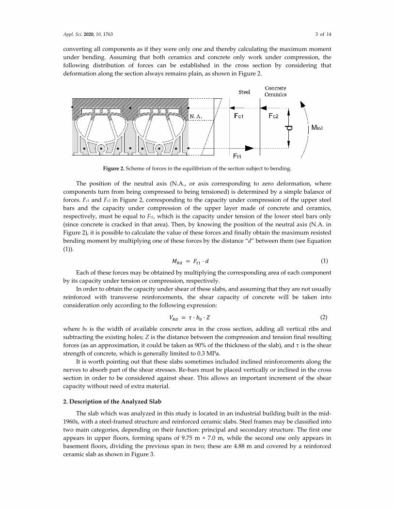
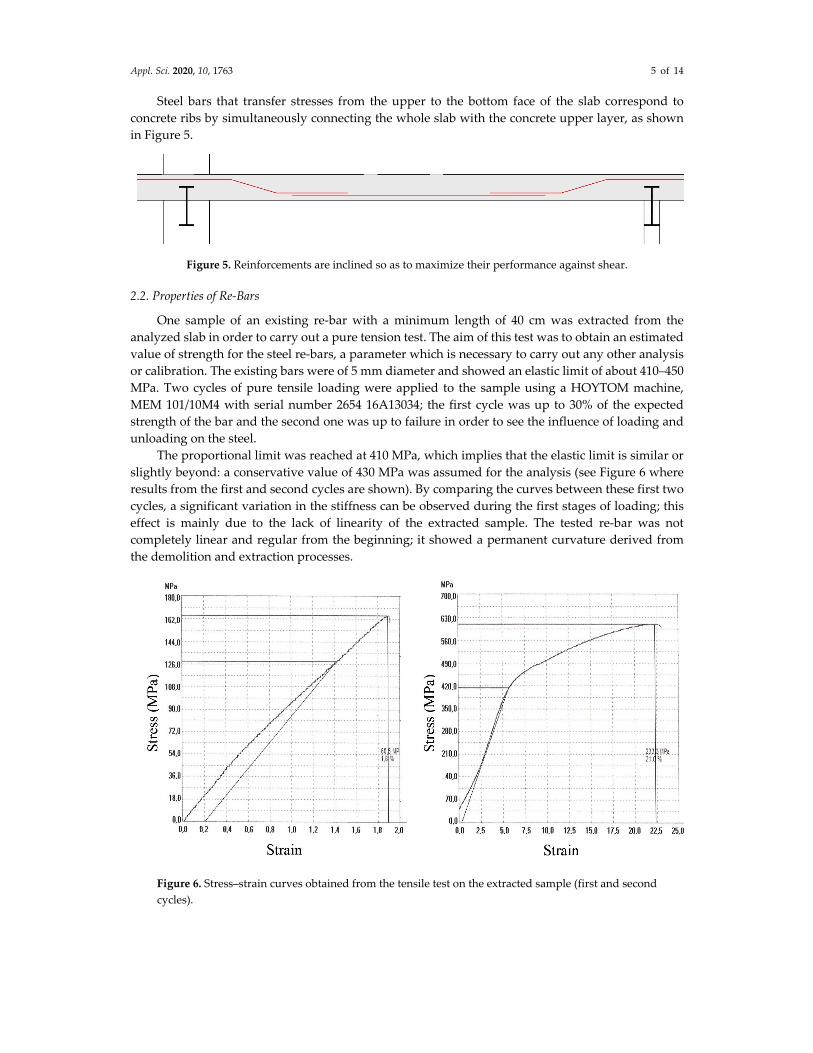
2.2. Properties of Re‐Bars
One sample of an existing re‐bar with a minimum length of 40 cm was extracted from the
analyzed slab in order to carry out a pure tension test. The aim of this test was to obtain an estimated
value of strength for the steel re‐bars, a parameter which is necessary to carry out any other analysis
or calibration. The existing bars were of 5 mm diameter and showed an elastic limit of about 410–450
MPa. Two cycles of pure tensile loading were applied to the sample using a HOYTOM machine,
MEM 101/10M4 with serial number 2654 16A13034; the first cycle was up to 30% of the expected
strength of the bar and the second one was up to failure in order to see the influence of loading and
unloading on the steel.
The proportional limit was reached at 410 MPa, which implies that the elastic limit is similar or
slightly beyond: a conservative value of 430 MPa was assumed for the analysis (see Figure 6 where
results from the first and second cycles are shown). By comparing the curves between these first two
cycles, a significant variation in the stiffness can be observed during the first stages of loading; this
effect is mainly due to the lack of linearity of the extracted sample. The tested re‐bar was not
completely linear and regular from the beginning; it showed a permanent curvature derived from
the demolition and extraction processes.
Figure 6. Stress–strain curves obtained from the tensile test on the extracted sample (first and second
cycles).

Appl. Sci. 2020, 10, 1763 6 of 14
2.3. Estimation of the Theoretical Load‐Bearing Capacity
By considering a total of 4 ribs per meter according to the typical cross section in Figure 2, a
minimum of 12 bars of 5 mm diameter per meter was considered in the lower section of the mid‐span
areas, while no bars were assumed within the upper part (only concrete); this corresponds to a typical
distribution of reinforcements against positive bending moments (those appearing at mid‐span
areas). On the contrary, in supporting areas, there were 12 reinforcing bars in upper levels without
any in the lower section. By using the approximation proposed by Seguí [4] in the ITEC manual to
determine the load‐bearing strength of ceramic‐reinforced slabs, it is possible to estimate the ultimate
load‐bearing capacity.
In order to calculate the ultimate bending moment capacity, we firstly need the position of the
neutral axis under positive (mid‐span areas) and negative (supporting areas) bending moments. This
may be obtained by starting with the total capacity of reinforcements:
𝐹 12 𝑟𝑒𝑏𝑎𝑟𝑠 19.62 mm2 413 MPa 97.2 kN. (3)
The position of the neutral axis in the case of positive bending may be estimated by equating the
total area of concrete which is needed in the upper layer with the maximum tensile capacity of
reinforcing bars:
𝐹 𝐹 → ℎ 1000 mm 15 MPa 97.200 N,
ℎ 6.48 mm. (4)
Thus, the position of the neutral axis almost coincides with the upper layer of the slab, so the
distance “d” is
𝑑 230 mm 6.48 25 198.52 mm (5)
and the final resisted positive bending moment is
𝑀 𝐹 𝑑 97.2 𝑘𝑁 0.198 m 19.24 kNm. (6)
On the contrary, in the case of supporting areas, the tensile force appears in upper layers and it
is the concrete of the ribs in the lower levels which resists compression stresses. These ribs sum to a
total width of 60 cm (15 cm per ceramic piece, and four pieces per meter). Then, the neutral axis is
𝐹 𝐹 → ℎ 600 mm 15 MPa 97.200 N,
ℎ 10.80 mm. (7)
The distance “d” is 194.2 mm, and the ultimate resisted bending moment is slightly lower in this
case:
𝑀 𝐹 𝑑 97.2 kN 0.194 m 18.85 kNm. (8)
Regarding the load‐bearing capacity, it is evident that the contribution of concrete is very low.
Thus, by assuming the span of the tested slab, and due to the hypothesis of continuity on both
supporting edges thanks to the previous shoring of the steel structure, the maximum theoretical
uniform load that could be resisted by this particular ceramic‐reinforced slab (obviously considering
only the bending moment) would be
𝑀 𝑞𝐿12
→ 𝑞 𝑀12𝐿
18.85 kNm12
4.80 9.81 kN/m . (9)
The performance of a flat slab (especially with short span) is not only characterized by the
bending strength; we obviously need to also consider the shear resistance. By again following the
expressions proposed by Segui [4], the total capacity against shear of a ceramic‐reinforced slab would
be
𝑉 0.3 MPa 200 mm 194 mm 11.64 kN/mL. (10)
Appl. Sci. 2020, 10, 1763 7 of 14
This value is relatively low compared with usual acting shear forces, especially compared with
the bending capacity of the same slabs; this is the reason why there are bars inclined at 45° in the
principal ribs of the section (see Figure 5), to enhance the shear response of the section. These inclined
re‐bars provide extra capacity against shear that may be quantified as
Δ𝑉 4 re bars 19.62 mm2 413 𝑀𝑃𝑎 32.41kN. (11)
Finally, the maximum shear capacity of the slab by considering both contributions (concrete and
steel) is about 44.05 kN/mL. Assuming a span of 4.88 m, as in case of the tested slab, the maximum
uniformly distributed load that could be resisted according to shear would be
𝑉 , 44.05𝑘𝑁𝑚𝐿
𝑞 ∗𝐿2→ 𝑞 𝑉 ,
2𝐿
44.05 ∗2
4.88 18.35 kN/m . (12)
In conclusion, the theoretical failure loads (without safety factors) of the analyzed ceramic‐
reinforced slab, obtained by using the formulation proposed in the literature by Seguí [4], are shown
in Table 1.
Table 1. Calculated failure loads of the slab (without safety factors). Adapted from [4].
Failure Mode Maximum
Theoretical Load
Positive bending (mid‐span area) 19.62 kN/m2
Negative bending (supporting areas) 9.81 kN/m2
Shear 18.35 kN/m2
Assuming the hypothesis of full continuity at both supporting edges, negative bending at the
supports is the most restrictive mode of collapse, with a theoretical failure load of 9.81 kN/m2.
3. Loading Test
3.1. Objective
The main objective of the test was to describe the real load‐bearing capacity and behavior of the
analyzed slab, as well as the cyclic loading–unloading response. Due to the industrial use of the
building, the testing load was established as 7.5 kN/m2 uniformly distributed over all the area,
assuming that this load is already close to the predicted failure.
3.2. Methodology
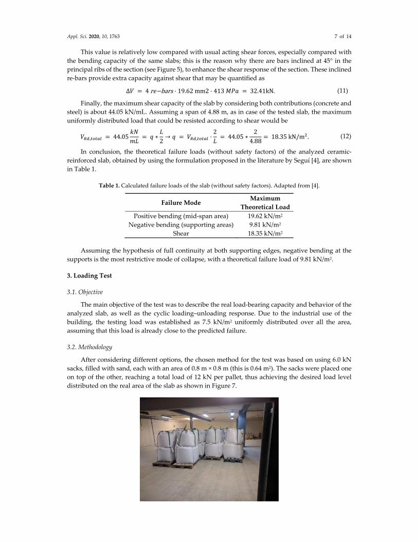
After considering different options, the chosen method for the test was based on using 6.0 kN
sacks, filled with sand, each with an area of 0.8 m × 0.8 m (this is 0.64 m2). The sacks were placed one
on top of the other, reaching a total load of 12 kN per pallet, thus achieving the desired load level
distributed on the real area of the slab as shown in Figure 7.
Appl. Sci. 2020, 10, 1763 8 of 14
Figure 7. General view of the loading test with sand sacks.
As previously mentioned, the main goal of the load‐bearing test was to determinate the capacity
of the ceramic‐reinforced slab itself, independently of the capacity of the steel structure; this is the
reason why the latter was completely shored up to avoid interference (see Figure 7). Otherwise,
deflections of the steel beams would affect the results of the test, assuming that it was dealing strictly
with the slab. This way, the load was only applied on the slab area by keeping the beams infinitely
rigid; this makes the upper reinforcements start to work actively in terms of continuity of the negative
bending moments. By restricting both steel beams against deformation, the tested slab may be
considered continuous on the two supporting edges.
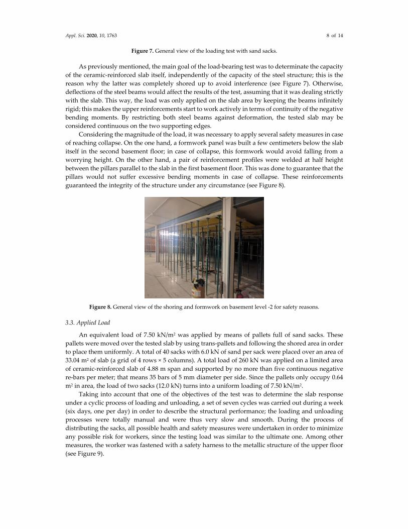
Considering the magnitude of the load, it was necessary to apply several safety measures in case
of reaching collapse. On the one hand, a formwork panel was built a few centimeters below the slab
itself in the second basement floor; in case of collapse, this formwork would avoid falling from a
worrying height. On the other hand, a pair of reinforcement profiles were welded at half height
between the pillars parallel to the slab in the first basement floor. This was done to guarantee that the
pillars would not suffer excessive bending moments in case of collapse. These reinforcements
guaranteed the integrity of the structure under any circumstance (see Figure 8).
Figure 8. General view of the shoring and formwork on basement level ‐2 for safety reasons.
3.3. Applied Load
An equivalent load of 7.50 kN/m2 was applied by means of pallets full of sand sacks. These
pallets were moved over the tested slab by using trans‐pallets and following the shored area in order
to place them uniformly. A total of 40 sacks with 6.0 kN of sand per sack were placed over an area of
33.04 m2 of slab (a grid of 4 rows × 5 columns). A total load of 260 kN was applied on a limited area
of ceramic‐reinforced slab of 4.88 m span and supported by no more than five continuous negative
re‐bars per meter; that means 35 bars of 5 mm diameter per side. Since the pallets only occupy 0.64
m2 in area, the load of two sacks (12.0 kN) turns into a uniform loading of 7.50 kN/m2.
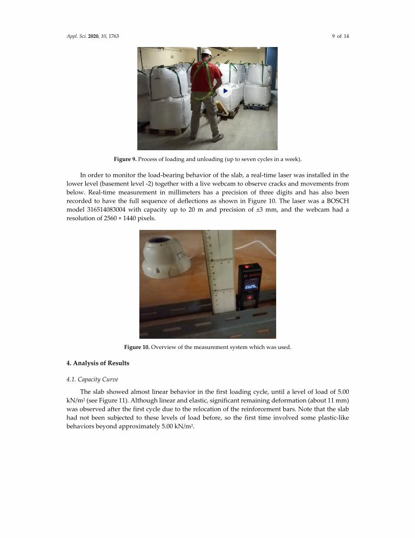
Taking into account that one of the objectives of the test was to determine the slab response
under a cyclic process of loading and unloading, a set of seven cycles was carried out during a week
(six days, one per day) in order to describe the structural performance; the loading and unloading
processes were totally manual and were thus very slow and smooth. During the process of
distributing the sacks, all possible health and safety measures were undertaken in order to minimize
any possible risk for workers, since the testing load was similar to the ultimate one. Among other
measures, the worker was fastened with a safety harness to the metallic structure of the upper floor
(see Figure 9).
Appl. Sci. 2020, 10, 1763 9 of 14
Figure 9. Process of loading and unloading (up to seven cycles in a week).
In order to monitor the load‐bearing behavior of the slab, a real‐time laser was installed in the
lower level (basement level ‐2) together with a live webcam to observe cracks and movements from
below. Real‐time measurement in millimeters has a precision of three digits and has also been
recorded to have the full sequence of deflections as shown in Figure 10. The laser was a BOSCH
model 316514083004 with capacity up to 20 m and precision of ±3 mm, and the webcam had a
resolution of 2560 × 1440 pixels.
Figure 10. Overview of the measurement system which was used.
4. Analysis of Results
4.1. Capacity Curve
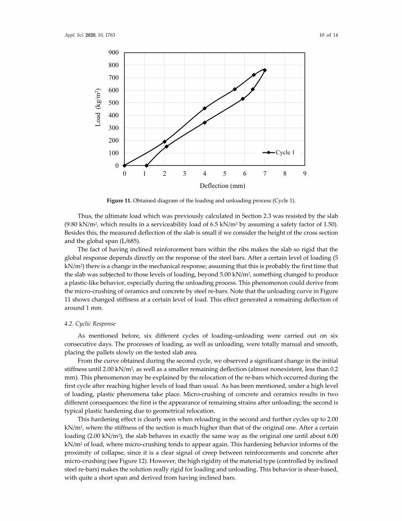
The slab showed almost linear behavior in the first loading cycle, until a level of load of 5.00
kN/m2 (see Figure 11). Although linear and elastic, significant remaining deformation (about 11 mm)
was observed after the first cycle due to the relocation of the reinforcement bars. Note that the slab
had not been subjected to these levels of load before, so the first time involved some plastic‐like
behaviors beyond approximately 5.00 kN/m2.
Appl. Sci. 2020, 10, 1763 10 of 14
Figure 11. Obtained diagram of the loading and unloading process (Cycle 1).
Thus, the ultimate load which was previously calculated in Section 2.3 was resisted by the slab
(9.80 kN/m2, which results in a serviceability load of 6.5 kN/m2 by assuming a safety factor of 1.50).
Besides this, the measured deflection of the slab is small if we consider the height of the cross section
and the global span (L/685).
The fact of having inclined reinforcement bars within the ribs makes the slab so rigid that the
global response depends directly on the response of the steel bars. After a certain level of loading (5
kN/m2) there is a change in the mechanical response; assuming that this is probably the first time that
the slab was subjected to those levels of loading, beyond 5.00 kN/m2, something changed to produce
a plastic‐like behavior, especially during the unloading process. This phenomenon could derive from
the micro‐crushing of ceramics and concrete by steel re‐bars. Note that the unloading curve in Figure
11 shows changed stiffness at a certain level of load. This effect generated a remaining deflection of
around 1 mm.
4.2. Cyclic Response
As mentioned before, six different cycles of loading–unloading were carried out on six
consecutive days. The processes of loading, as well as unloading, were totally manual and smooth,
placing the pallets slowly on the tested slab area.
From the curve obtained during the second cycle, we observed a significant change in the initial
stiffness until 2.00 kN/m2, as well as a smaller remaining deflection (almost nonexistent, less than 0.2
mm). This phenomenon may be explained by the relocation of the re‐bars which occurred during the
first cycle after reaching higher levels of load than usual. As has been mentioned, under a high level
of loading, plastic phenomena take place. Micro‐crushing of concrete and ceramics results in two
different consequences: the first is the appearance of remaining strains after unloading; the second is
typical plastic hardening due to geometrical relocation.
This hardening effect is clearly seen when reloading in the second and further cycles up to 2.00
kN/m2, where the stiffness of the section is much higher than that of the original one. After a certain
loading (2.00 kN/m2), the slab behaves in exactly the same way as the original one until about 6.00
kN/m2 of load, where micro‐crushing tends to appear again. This hardening behavior informs of the
proximity of collapse, since it is a clear signal of creep between reinforcements and concrete after
micro‐crushing (see Figure 12). However, the high rigidity of the material type (controlled by inclined
steel re‐bars) makes the solution really rigid for loading and unloading. This behavior is shear‐based,
with quite a short span and derived from having inclined bars.
0
100
200
300
400
500
600
700
800
900
0 1 2 3 4 5 6 7 8 9
Loa
d (
kg/m
2 )
Deflection (mm)
Cycle 1

Appl. Sci. 2020, 10, 1763 11 of 14
Figure 12. Overview of the loading and unloading process (Cycle 1 and Cycle 2).
From the curves which were obtained in the following cycles up to the sixth, no loss of ultimate
loading capacity was observed. At each cycle, the load reaches a value of 7.50 kN/m2, although each
time there is a slight reduction of stiffness. After the second cycle, the pattern of loading and
unloading is almost the same for all cycles, except for the first loading steps during the last two cycles,
where plastic hardening plays a significant role (see Figure 13. This phenomenon goes hand in hand
with a clear reduction of remaining strains; both effects are clear signals of a certain damage process
within the slab when subjected repeatedly to high levels of loading and unloading in consecutive
cycles.
Figure 13. Overview of the loading and unloading process (several cycles).
All these results lead to the conclusion that this type of slab is very rigid due to its shear‐based
response and dependence on reinforcements. This rigidity does not decrease significantly when
repeating cycles up to high rates of loading.
0
100
200
300
400
500
600
700
800
900
0 1 2 3 4 5 6 7 8 9
Loa
d (k
g/m
2 )
Deflection (mm)
Cycle 1
Cycle 2
0
100
200
300
400
500
600
700
800
900
0 1 2 3 4 5 6 7 8 9
Loa
d (k
g/m
2 )
Deflection (mm)
Cycles 1 to 5
Cycle 6
1 2 3 4 5 6
Appl. Sci. 2020, 10, 1763 12 of 14
5. Vibrational Response
Vibrations which are induced by human walking or machines on slabs become seriously
disturbing when the fundamental frequencies are below 7–8 Hz according to most Standards,
including the “Design of Floor Structures for Human Induced Vibrations” [7]. In slabs of relatively
low self‐weight compared with the load‐bearing capacity, dynamic analysis is needed in order to
avoid comfort problems during serviceability [8–13].
5.1. Estimation of the Elemental Frequency of the Slab Cross Section
In order to estimate the fundamental frequency of the structure, assuming full continuity of the
slab and the beams at both supporting edges in the two cases, the following simplified expression
according to [7] may be used:
𝑓 4/𝜋 3 𝐸 𝐼/ 0.37 𝜇 𝐿 (13)
where E is the estimated elastic modulus of the section, I is the moment of inertia of the cross section,
μ is the total weight in a width of one meter of slab (including live load), and L is the span of the slab.
In the case of one‐way slabs supported by steel beams, like in this case, the fundamental
frequency of the whole structure (fea) may be calculated as the combination of both frequencies (the
frequency f1 of the slab and the frequency f2 of the I‐beam) by means of the Dunkerley [7] expression:
1 𝑓 1 𝑓⁄ 1 𝑓⁄⁄ 14
We consider a moment of inertia of the equivalent section of 270,843,903 mm4 (measured from
section of Figure 4) and obtain an approximated elasticity modulus E of the whole slab by using the
value of deflection obtained in the experimental test during the first cycle of loading:
𝛿 5 𝑊𝐿
384 𝐸 𝐼 → 𝐸 5 𝑊 𝐿 / 384 𝛿 𝐼 . 15
Then, by substituting the obtained value of deflection in the first cycle (7 mm) into the latter
expression, generated by a uniform load of 7.50 kN/m2, it is possible to estimate the secant elastic
modulus:
𝐸 5 3504500
384 7 270843903 97137 MPa. (16)
Regarding the steel I‐beams, it is possible to calculate quite accurately the fundamental
frequency by using the same expression [8]. The mentioned beams are IPN400 profiles (typical steel
I‐beam cross section of 400 mm height, widely used in Europe) with 7 m span, 104 mm4 moment of
inertia, and elastic modulus of 210,000 MPa, characteristic of steel.
Then, by considering all previous expressions and the real self‐weight (slab + pavement = 2.2 +
1.0 = 3.2 kN/m2), the fundamental frequencies of the whole structure were estimated for different
loading levels.
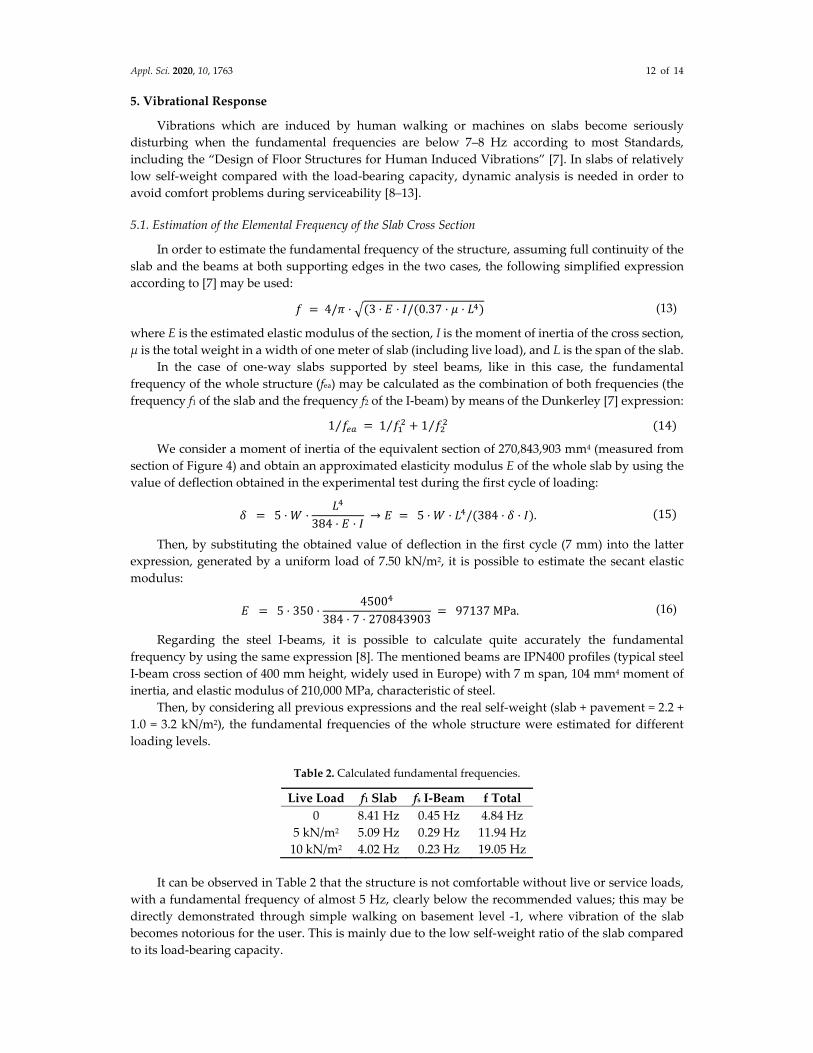
Table 2. Calculated fundamental frequencies.
Live Load f1 Slab fs I‐Beam f Total
0 8.41 Hz 0.45 Hz 4.84 Hz
5 kN/m2 5.09 Hz 0.29 Hz 11.94 Hz
10 kN/m2 4.02 Hz 0.23 Hz 19.05 Hz
It can be observed in Table 2 that the structure is not comfortable without live or service loads,
with a fundamental frequency of almost 5 Hz, clearly below the recommended values; this may be
directly demonstrated through simple walking on basement level ‐1, where vibration of the slab
becomes notorious for the user. This is mainly due to the low self‐weight ratio of the slab compared
to its load‐bearing capacity.
Appl. Sci. 2020, 10, 1763 13 of 14
Note that the higher the applied load, the higher the fundamental frequency of the structure,
although in any case the frequencies are especially high. This is typical of low‐weight structures with
high load‐bearing capacities. These are the reasons why this type of slab was widely used especially
for industrial buildings, where heavy machines worked with high frequencies; slabs with high
capabilities and low frequencies were needed.
6. Conclusions
Derived from the analysis and the real loading test in particular, the results show that the typical
ceramic‐reinforced slabs that were built during the 1960s and 1970s in Spain are rigid solutions with
very high load‐bearing capacities. The results from the test allow us to conclude that the analyzed
slab, 230 mm thick and only 2.2 kN/m2 in weight, resists up to 7.5 kN/m2 extra live load.
Besides this, the structural response of the slab is mostly elastic up to advanced steps of loading,
with all the advantages that this behavior implies. However, a slight plastic response was detected
beyond approximately 5 kN/m2, as this load level had never been reached before; the fact of going
beyond the current load states implies a redistribution of the reinforcements within the section that
results in plastic remaining strains (see the diagrams in Section 4). This effect is even enhanced when
the load is cyclically repeated, although an evident hardening effect was also observed in the first
early stages of loading. The hardening effect is directly derived from the relocation of re‐bars, which
takes place the first time and hardens during the following cycles.
The results from the loading test show that deflections on the analyzed slab were very low
compared with those on other slab types. The maximum mid‐span deflection of the analyzed slab
was 7 mm under 7.50 kN/m2, which corresponds to L/685. This is mainly due to the structural
response of the solution, which is mainly based on shear behavior and steel reinforcements.
Deflections of the slab are mostly those derived from steel re‐bars, with little interference by concrete
and its typical creep.
The slab response under vibration was better as the live load was increased. As a low self‐weight
solution with enhanced load‐bearing capacity, problems derive more from serviceability than from
ultimate strengths. This means that the analyzed slab, as a typical example of the ceramic‐reinforced
slabs which were used throughout Spain, works better when loaded in terms of dynamic response.
When not loaded, the slab is uncomfortable for users due to the low fundamental frequency, which
coincides with the vibration generated by humans walking. However, in the case of heavy machines
with high frequencies, this is an ideal solution.
For all these reasons, the typical ceramic‐reinforced slabs which were used during the 1960s,
1970s, and even later in Spain, especially for industrial buildings, are very powerful slab solutions
from all points of view. It is curious to see how a specific solution for slabs which is currently outside
of the Standards is so efficient from several points of view. Obviously, always limiting spans under
5.00 m, as in the analyzed case, means it works basically under shear. This study on ceramic‐
reinforced slabs verifies that these specific solutions with almost no concrete work efficiently for some
specific cases, which is opposite to the current Standard’s postulates.
Author Contributions: The four authors were involved in the conceptualization, methodology, formal analysis,
investigation, and data curation of this study. Writing—original draft: A.R.‐R.; A.A.‐V. and I.C.‐C; Writing—
review and editing: A.A.‐V.; A.R.‐R. and D.G.‐C. All authors have read and agreed to the published version of
the manuscript.
Funding: This research received no external funding.
Acknowledgments: We acknowledge the Serra Hunter Program for providing funds to carry out this research.
Alicia Rivera‐Rogel acknowledges the financial support received from the “Secretaría de Educación Superior,
Ciencia, Tecnología e Innovación” (SENESCYT) for her doctoral studies at Polytechnic University of Catalonia
(UPC).
Conflicts of Interest: The authors declare no conflict of interest.

Appl. Sci. 2020, 10, 1763 14 of 14
References
1. Institut de Tecnologia de la Construcció – ITEC. Recomendaciones para la Terapia de Forjados Unidireccionales
de Viguetas Autoportantes de Hormigón (“Recommendations for the Therapy of Unidirectional Slabs of Self‐
Supporting Concrete Joists”). Generalitat de Catalunya; Departamento de Política Territorial y Obras
Públicas; Dirección General de Arquitectura y Urbanismo. Barcelona, 1992, 1, 1‐132. [in Spanish].
2. Trias de Bes, J.; Casariego, P. The art of the technology: Construction of structures by domed ceramic with
industrial systems. Informes de la Construcción. 2016, 68, 169.
3. Gemma, M.S. Las últimas construcciones de fábrica de ladrillo resistente: La generación de los años
cincuenta a los setenta (“The last resistant brick factory constructions: The generation from the fifties to the
seventies”). In Actas del Séptimo Congreso Nacional de Historia de la Construcción, Santiago de Compostela;
Instituto Juan de Herrera: Santiago de Compostela, La Coruña, Spain, 26‐29 de octubre, 2011. [in Spanish].
4. Víctor, S. Recomanacions per al reconeixement, la diagnosi i la teràpia de sostres ceràmics In
Recommendations for the Recognition, Diagnosis and the Therapy of Ceramics Slab; Indian Technical and
Economic Cooperation: Barcelona, Spain, 1995.
5. Laureà, M. Forjados cerámicos: Estudio de un colapso (“Ceramic slabs: Study of a collapse”). Associació de
Consultors dʹEstructures 2011, 42, 28–35. [in Spanish].
6. Ramón, B.J. Los forjados de cerámica armada antes y después de la primera instrucción de cálculo a rotura
(“Reinforced ceramic floor slabs before and after the first breakage calculation instruction”). Associació de
Consultors dʹEstructures 2012, 43, 5–21.
7. Feldmann, M., Heinemeyer, Ch., Butz, Chr., Caetano, E., Cunha, A., Galanti, A., Goldack, O., Hechler, O.,
Hicks, S., Keil, A., Lukic, M., Obiala, R., Schlaich, M., Sedlacek, G., Smith, A., Waarts, P. Design of Floor
Structures for Human Induced Vibrations. JRC Scientific and Technical Reports. Joint report, prepared under
the JRC‐ECCS cooperation agreement for the evolution of Eurocode 3 (programme of CEN TC 250).
Luxemburg. 2009, 1‐75.
8. Sedlacek, G., Heinemeyer, C., Butz, C., VEILING, B., Waarts, P., Van Duin, F., Hicks, S., Devine, P. and
Demarco, T. Generalisation of criteria for floor vibrations for industrial, office, residential and public
building and gymnastic halls. European Commission—Technical Steel Research. Report EUR 21972 EN, 2006,
1‐343.
9. Wendell, V.; Ronaldo, B. Control of vibrations induced by people walking on large span composite floor
decks. Eng. Struct. 2011, 33, 2485–2494.
10. Nguyen Huu, A.T. Walking induced floor vibration design and control. Ph. D. Thesis, Swinburne University
of Technology, Melbourne, VIC, Australia, 2013.
11. da Silva, J.G.; de Andrade, S.A.; Lopes, E.D. Parametric modelling of the dynamic behaviour of a steel–
concrete composite floor. Eng. Struct. 2014, 75, 327–339.
12. Mohammed, A.S.; Pavic, A.; Racic, V. Improved model for human induced vibrations of high‐frequency
floors. Eng. Struct. 2018, 168, 950–966.
13. Machado, W.G.; da Silva, A.R.; das Neves, F.D.A. Dynamic analysis of composite beam and floors with
deformable connection using plate, bar and interface elements. Eng. Struct. 2019, 184, 247–256.
© 2020 by the authors. Licensee MDPI, Basel, Switzerland. This article is an open access
article distributed under the terms and conditions of the Creative Commons Attribution
(CC BY) license (http://creativecommons.org/licenses/by/4.0/).