ReadyDATA 5200 Hardware Manual - Netgear · 350 East Plumeria Drive San Jose, CA 95134 USA December...
38
350 East Plumeria Drive San Jose, CA 95134 USA December 2012 202-11024-03 ReadyDATA 5200 Hardware Manual
Transcript of ReadyDATA 5200 Hardware Manual - Netgear · 350 East Plumeria Drive San Jose, CA 95134 USA December...
350 East Plumeria Drive
San Jose, CA 95134
USA
December 2012
202-11024-03
ReadyDATA 5200Hardware Manual
2
NETGEAR ReadyDATA 5200
SupportThank you for selecting NETGEAR products.
After installing your device, locate the serial number on the label of your product and use it to register your product at https://my.netgear.com. You must register your product before you can use NETGEAR telephone support. NETGEAR recommends registering your product through the NETGEAR website. For product updates and web support, visit http://support.netgear.com.
Phone (US & Canada only): 1-888-NETGEAR.
Phone (Other Countries): Check the list of phone numbers at http://support.netgear.com/general/contact/default.aspx.
TrademarksNETGEAR, the NETGEAR logo, and Connect with Innovation are trademarks and/or registered trademarks of NETGEAR, Inc. and/or its subsidiaries in the United States and/or other countries. Information is subject to change without notice. © 2012 All rights reserved.
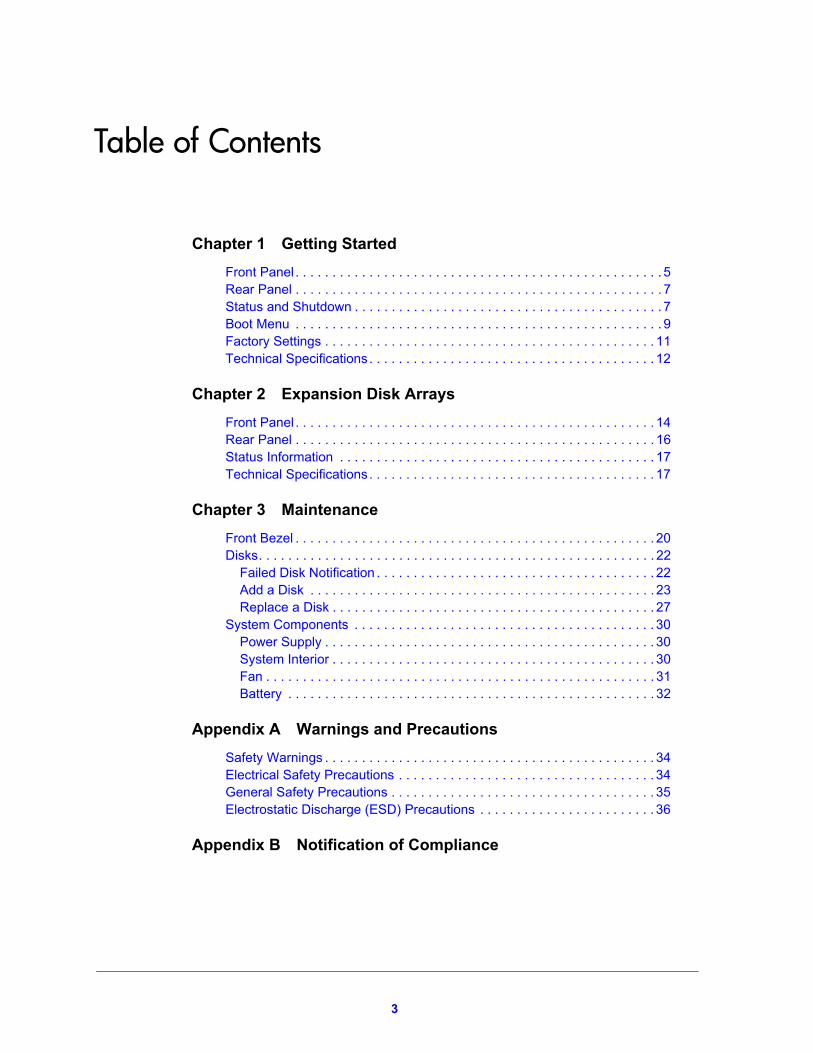
Table of Contents
Chapter 1 Getting Started
Front Panel . . . . . . . . . . . . . . . . . . . . . . . . . . . . . . . . . . . . . . . . . . . . . . . . . . 5Rear Panel . . . . . . . . . . . . . . . . . . . . . . . . . . . . . . . . . . . . . . . . . . . . . . . . . . 7Status and Shutdown . . . . . . . . . . . . . . . . . . . . . . . . . . . . . . . . . . . . . . . . . . 7Boot Menu . . . . . . . . . . . . . . . . . . . . . . . . . . . . . . . . . . . . . . . . . . . . . . . . . . 9Factory Settings . . . . . . . . . . . . . . . . . . . . . . . . . . . . . . . . . . . . . . . . . . . . . 11Technical Specifications. . . . . . . . . . . . . . . . . . . . . . . . . . . . . . . . . . . . . . . 12
Chapter 2 Expansion Disk Arrays
Front Panel . . . . . . . . . . . . . . . . . . . . . . . . . . . . . . . . . . . . . . . . . . . . . . . . . 14Rear Panel . . . . . . . . . . . . . . . . . . . . . . . . . . . . . . . . . . . . . . . . . . . . . . . . . 16Status Information . . . . . . . . . . . . . . . . . . . . . . . . . . . . . . . . . . . . . . . . . . . 17Technical Specifications. . . . . . . . . . . . . . . . . . . . . . . . . . . . . . . . . . . . . . . 17
Chapter 3 Maintenance
Front Bezel . . . . . . . . . . . . . . . . . . . . . . . . . . . . . . . . . . . . . . . . . . . . . . . . . 20Disks. . . . . . . . . . . . . . . . . . . . . . . . . . . . . . . . . . . . . . . . . . . . . . . . . . . . . . 22
Failed Disk Notification . . . . . . . . . . . . . . . . . . . . . . . . . . . . . . . . . . . . . . 22Add a Disk . . . . . . . . . . . . . . . . . . . . . . . . . . . . . . . . . . . . . . . . . . . . . . . 23Replace a Disk . . . . . . . . . . . . . . . . . . . . . . . . . . . . . . . . . . . . . . . . . . . . 27
System Components . . . . . . . . . . . . . . . . . . . . . . . . . . . . . . . . . . . . . . . . . 30Power Supply . . . . . . . . . . . . . . . . . . . . . . . . . . . . . . . . . . . . . . . . . . . . . 30System Interior . . . . . . . . . . . . . . . . . . . . . . . . . . . . . . . . . . . . . . . . . . . . 30Fan . . . . . . . . . . . . . . . . . . . . . . . . . . . . . . . . . . . . . . . . . . . . . . . . . . . . . 31Battery . . . . . . . . . . . . . . . . . . . . . . . . . . . . . . . . . . . . . . . . . . . . . . . . . . 32
Appendix A Warnings and Precautions
Safety Warnings . . . . . . . . . . . . . . . . . . . . . . . . . . . . . . . . . . . . . . . . . . . . . 34Electrical Safety Precautions . . . . . . . . . . . . . . . . . . . . . . . . . . . . . . . . . . . 34General Safety Precautions . . . . . . . . . . . . . . . . . . . . . . . . . . . . . . . . . . . . 35Electrostatic Discharge (ESD) Precautions . . . . . . . . . . . . . . . . . . . . . . . . 36
Appendix B Notification of Compliance
3
1
1. Getting StartedCongratulations on your purchase of a NETGEAR® ReadyDATATM 5200. This ReadyDATA 5200 Hardware Manual describes the physical features of the ReadyDATA 5200. This chapter includes the following sections:
• Front Panel
• Rear Panel
• Status and Shutdown
• Boot Menu
• Factory Settings
• Technical Specifications
This manual assumes that your ReadyDATA 5200 has been installed in a rack according to the instructions in the NETGEAR ReadyDATA 5200 Installation Guide.
For detailed information about configuring, managing, and using your ReadyDATA 5200 storage system, see the ReadyDATA OS Software Manual, which is available on the Resource CD that came with your storage system and at http://support.netgear.com.
4
NETGEAR ReadyDATA 5200
Front Panel
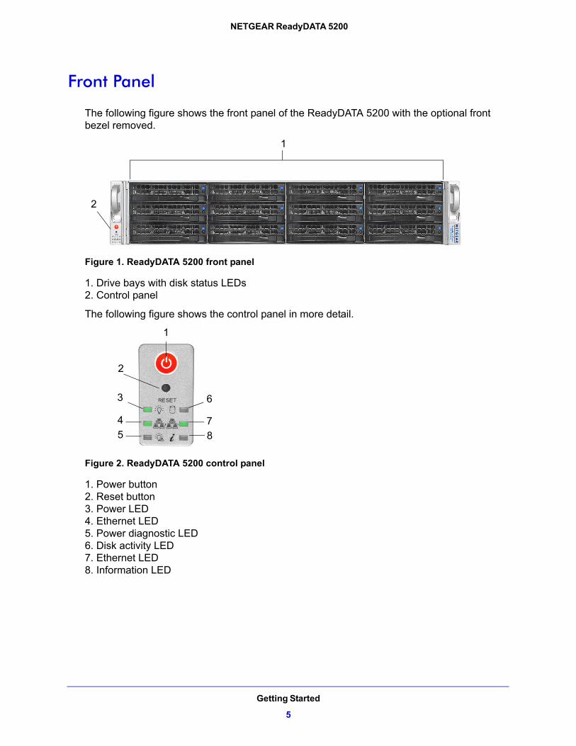
The following figure shows the front panel of the ReadyDATA 5200 with the optional front bezel removed.
1
2
Figure 1. ReadyDATA 5200 front panel
1. Drive bays with disk status LEDs2. Control panel
The following figure shows the control panel in more detail.
1
2
3
4
5
6
7
8
Figure 2. ReadyDATA 5200 control panel
1. Power button2. Reset button3. Power LED4. Ethernet LED5. Power diagnostic LED6. Disk activity LED7. Ethernet LED8. Information LED
Getting Started
5

NETGEAR ReadyDATA 5200
Each drive bay features a latch that releases the pop-out tray handle, as shown in the following figure.
1
2
Figure 3. Disk tray handle and release latch
1. Disk tray handle2. Disk tray release latch
WARNING:
No matter how many hard drives are installed in your system, ensure that all drive trays remain in the drive bays to maintain proper airflow.
For more information about adding and replacing disk drives, see Add a Disk on page 23 and Replace a Disk on page 27.
The ReadyDATA 5200 comes with an front bezel that protects the drive bays with a lockable cover. You can operate the ReadyDATA 5200 with or without the front bezel.
The following image shows a ReadyDATA 5200 with the front bezel installed.
Figure 4. ReadyDATA 5200 with front bezel installed
For more information about installing and removing the front bezel, see Front Bezel on page 20.
Getting Started
6
NETGEAR ReadyDATA 5200
Rear Panel
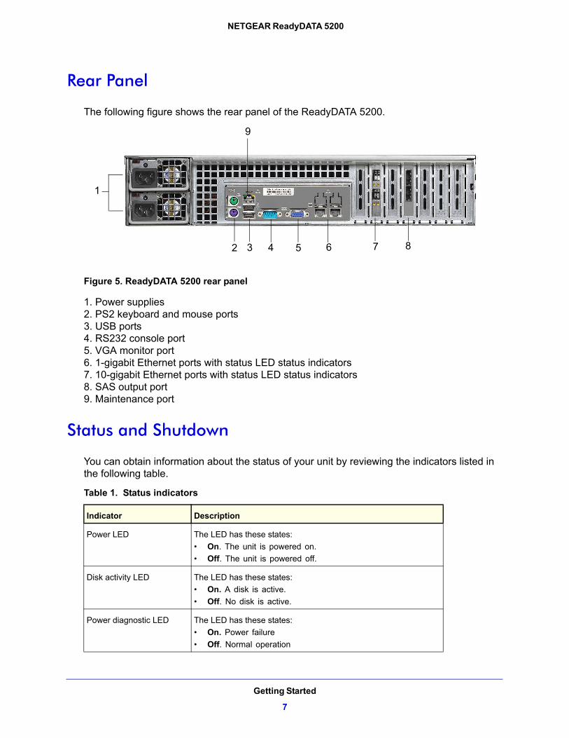
The following figure shows the rear panel of the ReadyDATA 5200.
1
2 3 4 5 6 7 8
9
Figure 5. ReadyDATA 5200 rear panel
1. Power supplies2. PS2 keyboard and mouse ports3. USB ports4. RS232 console port5. VGA monitor port6. 1-gigabit Ethernet ports with status LED status indicators7. 10-gigabit Ethernet ports with status LED status indicators8. SAS output port9. Maintenance port
Status and Shutdown
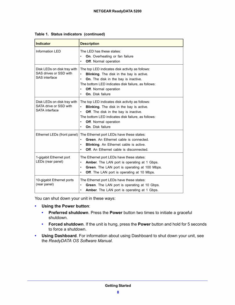
You can obtain information about the status of your unit by reviewing the indicators listed in the following table.
Table 1. Status indicators
Indicator Description
Power LED The LED has these states:
• On. The unit is powered on.
• Off. The unit is powered off.
Disk activity LED The LED has these states:
• On. A disk is active.
• Off. No disk is active.
Power diagnostic LED The LED has these states:
• On. Power failure
• Off. Normal operation
Getting Started
7
NETGEAR ReadyDATA 5200
You can shut down your unit in these ways:
• Using the Power button:
• Preferred shutdown. Press the Power button two times to initiate a graceful shutdown.
• Forced shutdown. If the unit is hung, press the Power button and hold for 5 seconds to force a shutdown.
• Using Dashboard. For information about using Dashboard to shut down your unit, see the ReadyDATA OS Software Manual.
Information LED The LED has these states:
• On. Overheating or fan failure
• Off. Normal operation
Disk LEDs on disk tray with SAS drives or SSD with SAS interface
The top LED indicates disk activity as follows:
• Blinking. The disk in the bay is active.
• On. The disk in the bay is inactive.
The bottom LED indicates disk failure, as follows:
• Off. Normal operation
• On. Disk failure
Disk LEDs on disk tray with SATA drive or SSD with SATA interface
The top LED indicates disk activity as follows:
• Blinking. The disk in the bay is active.
• Off. The disk in the bay is inactive.
The bottom LED indicates disk failure, as follows:
• Off. Normal operation
• On. Disk failure
Ethernet LEDs (front panel) The Ethernet port LEDs have these states:
• Green. An Ethernet cable is connected.
• Blinking. An Ethernet cable is active.
• Off. An Ethernet cable is disconnected.
1-gigabit Ethernet port LEDs (rear panel)
The Ethernet port LEDs have these states:
• Amber. The LAN port is operating at 1 Gbps.
• Green. The LAN port is operating at 100 Mbps.
• Off. The LAN port is operating at 10 Mbps.
10-gigabit Ethernet ports (rear panel)
The Ethernet port LEDs have these states:
• Green. The LAN port is operating at 10 Gbps.
• Amber. The LAN port is operating at 1 Gbps.
Table 1. Status indicators (continued)
Indicator Description
Getting Started
8
NETGEAR ReadyDATA 5200
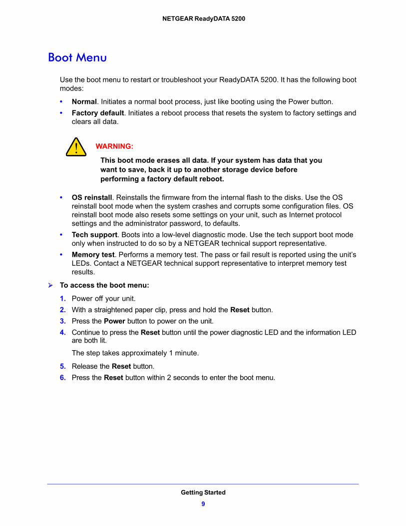
Boot Menu
Use the boot menu to restart or troubleshoot your ReadyDATA 5200. It has the following boot modes:
• Normal. Initiates a normal boot process, just like booting using the Power button.
• Factory default. Initiates a reboot process that resets the system to factory settings and clears all data.
WARNING:
This boot mode erases all data. If your system has data that you want to save, back it up to another storage device before performing a factory default reboot.
• OS reinstall. Reinstalls the firmware from the internal flash to the disks. Use the OS reinstall boot mode when the system crashes and corrupts some configuration files. OS reinstall boot mode also resets some settings on your unit, such as Internet protocol settings and the administrator password, to defaults.
• Tech support. Boots into a low-level diagnostic mode. Use the tech support boot mode only when instructed to do so by a NETGEAR technical support representative.
• Memory test. Performs a memory test. The pass or fail result is reported using the unit’s LEDs. Contact a NETGEAR technical support representative to interpret memory test results.
To access the boot menu:
1. Power off your unit.
2. With a straightened paper clip, press and hold the Reset button.
3. Press the Power button to power on the unit.
4. Continue to press the Reset button until the power diagnostic LED and the information LED are both lit.
The step takes approximately 1 minute.
5. Release the Reset button.
6. Press the Reset button within 2 seconds to enter the boot menu.
Getting Started
9
NETGEAR ReadyDATA 5200
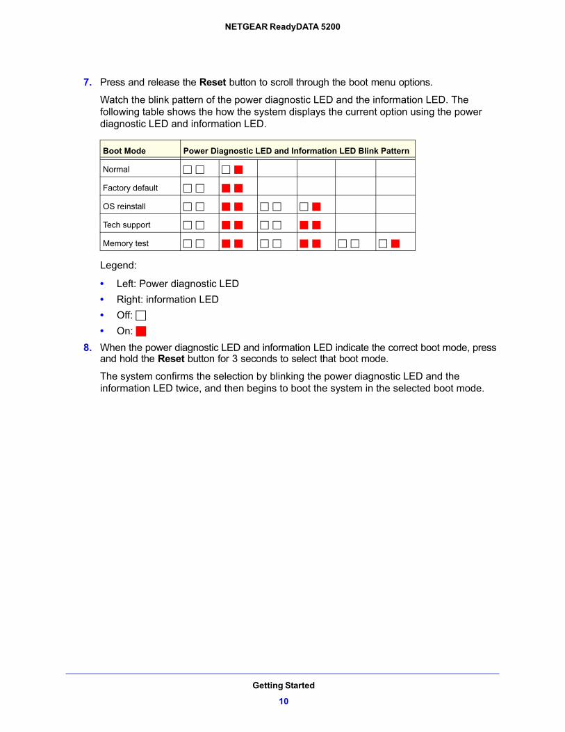
7. Press and release the Reset button to scroll through the boot menu options.
Watch the blink pattern of the power diagnostic LED and the information LED. The following table shows the how the system displays the current option using the power diagnostic LED and information LED.
Boot Mode Power Diagnostic LED and Information LED Blink Pattern
Normal
Factory default
OS reinstall
Tech support
Memory test
Legend:
• Left: Power diagnostic LED
• Right: information LED
• Off:
• On:
8. When the power diagnostic LED and information LED indicate the correct boot mode, press and hold the Reset button for 3 seconds to select that boot mode.
The system confirms the selection by blinking the power diagnostic LED and the information LED twice, and then begins to boot the system in the selected boot mode.
Getting Started
10
NETGEAR ReadyDATA 5200
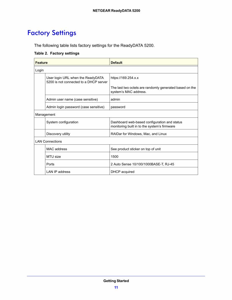
Factory Settings
The following table lists factory settings for the ReadyDATA 5200.
Table 2. Factory settings
Feature Default
Login
User login URL when the ReadyDATA 5200 is not connected to a DHCP server
https://169.254.x.x
The last two octets are randomly generated based on the system’s MAC address.
Admin user name (case sensitive) admin
Admin login password (case sensitive) password
Management
System configuration Dashboard web-based configuration and status monitoring built in to the system’s firmware
Discovery utility RAIDar for Windows, Mac, and Linux
LAN Connections
MAC address See product sticker on top of unit
MTU size 1500
Ports 2 Auto Sense 10/100/1000BASE-T, RJ-45
LAN IP address DHCP acquired
Getting Started
11
NETGEAR ReadyDATA 5200
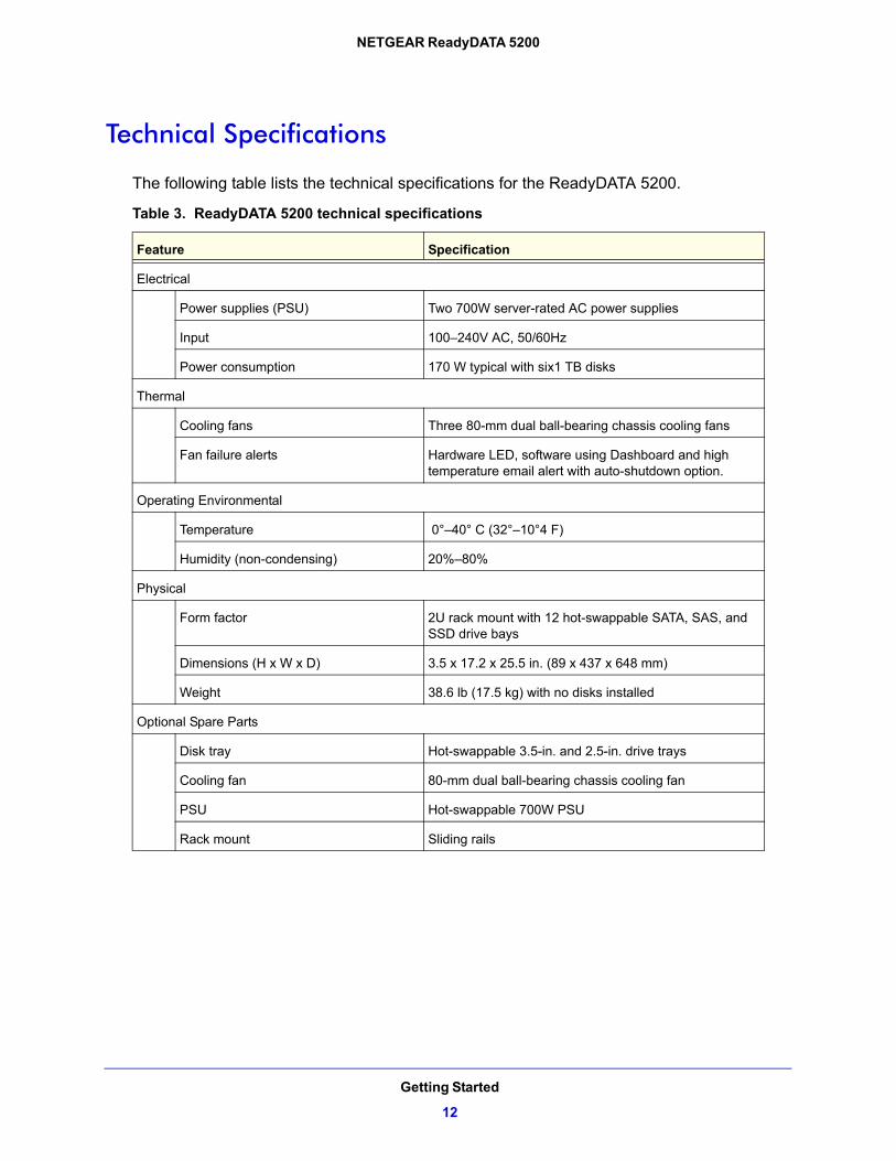
Technical Specifications
The following table lists the technical specifications for the ReadyDATA 5200.
Table 3. ReadyDATA 5200 technical specifications
Feature Specification
Electrical
Power supplies (PSU) Two 700W server-rated AC power supplies
Input 100–240V AC, 50/60Hz
Power consumption 170 W typical with six1 TB disks
Thermal
Cooling fans Three 80-mm dual ball-bearing chassis cooling fans
Fan failure alerts Hardware LED, software using Dashboard and high temperature email alert with auto-shutdown option.
Operating Environmental
Temperature 0°–40° C (32°–10°4 F)
Humidity (non-condensing) 20%–80%
Physical
Form factor 2U rack mount with 12 hot-swappable SATA, SAS, and SSD drive bays
Dimensions (H x W x D) 3.5 x 17.2 x 25.5 in. (89 x 437 x 648 mm)
Weight 38.6 lb (17.5 kg) with no disks installed
Optional Spare Parts
Disk tray Hot-swappable 3.5-in. and 2.5-in. drive trays
Cooling fan 80-mm dual ball-bearing chassis cooling fan
PSU Hot-swappable 700W PSU
Rack mount Sliding rails
Getting Started
12
2
2. Expansion Disk ArraysThis chapter describes physical features of the EDA2000 and EDA4000, which are optional expansion disk arrays you can use with the ReadyDATA 5200.
This manual assumes that your expansion disk array has been installed in a rack according to the instructions in the NETGEAR ReadyDATA 5200 Installation Guide.
The disk expansion arrays do not work independently; instead, they must be connected to a ReadyDATA 5200. For information about how to connect an expansion disk array to a ReadyDATA 5200, see the NETGEAR ReadyDATA 5200 Installation Guide that came with the EDA2000, EDA4000, and ReadyDATA 5200.
This chapter includes the following topics:
• Front Panel
• Rear Panel
• Status Information
• Technical Specifications
13
NETGEAR ReadyDATA 5200
Front Panel
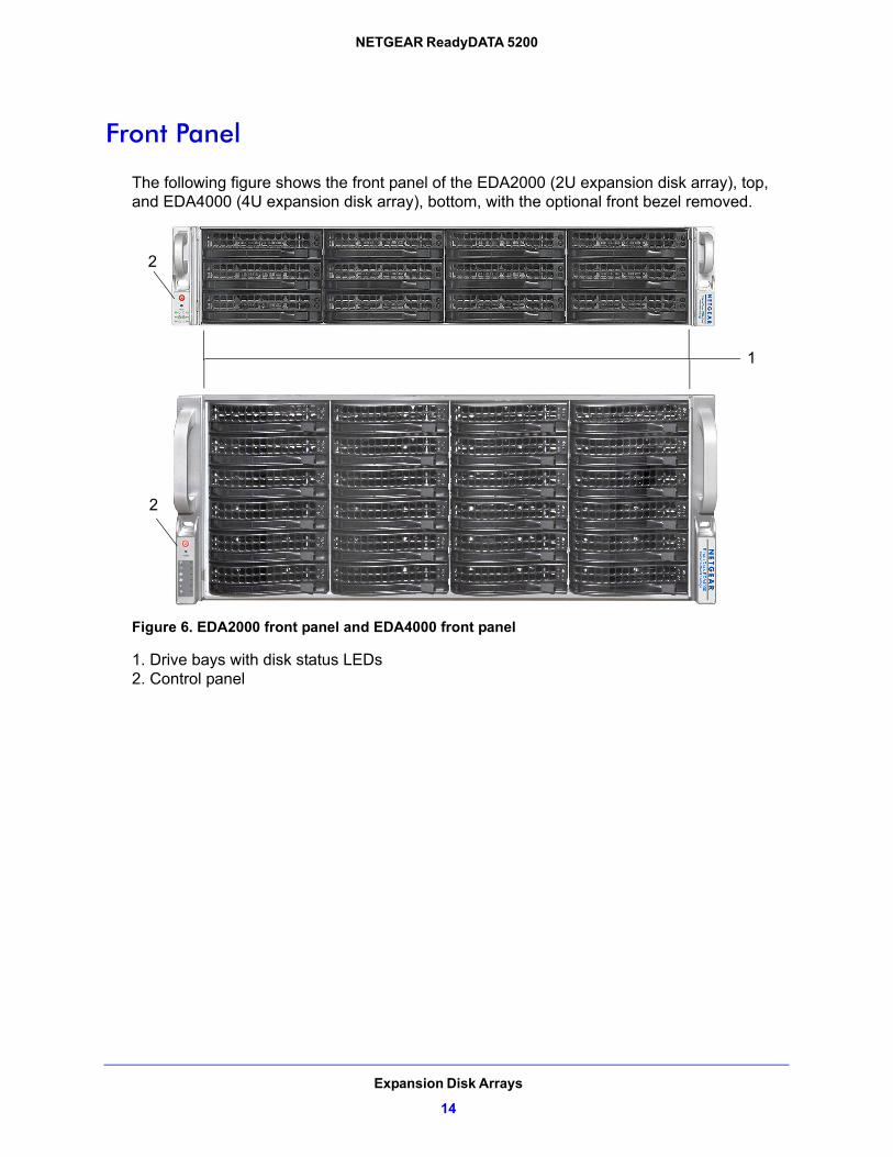
The following figure shows the front panel of the EDA2000 (2U expansion disk array), top, and EDA4000 (4U expansion disk array), bottom, with the optional front bezel removed.
2
2
1
Figure 6. EDA2000 front panel and EDA4000 front panel
1. Drive bays with disk status LEDs2. Control panel
Expansion Disk Arrays
14
NETGEAR ReadyDATA 5200
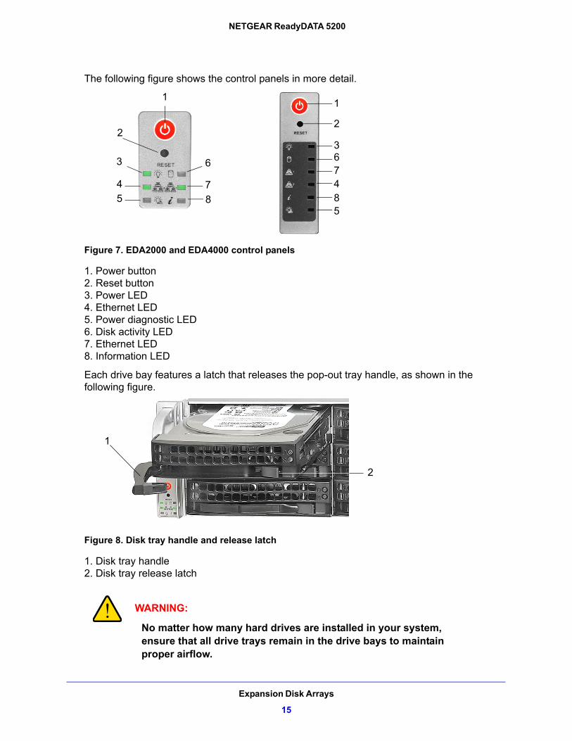
The following figure shows the control panels in more detail.
1
2
3
4
5
6
7
8
1
2
367485
Figure 7. EDA2000 and EDA4000 control panels
1. Power button2. Reset button3. Power LED4. Ethernet LED5. Power diagnostic LED6. Disk activity LED7. Ethernet LED8. Information LED
Each drive bay features a latch that releases the pop-out tray handle, as shown in the following figure.
1
2
Figure 8. Disk tray handle and release latch
1. Disk tray handle2. Disk tray release latch
WARNING:
No matter how many hard drives are installed in your system, ensure that all drive trays remain in the drive bays to maintain proper airflow.
Expansion Disk Arrays
15
NETGEAR ReadyDATA 5200
For more information about adding and replacing disk drives, see Add a Disk on page 23 and Replace a Disk on page 27.
The EDA 2000 and EDA 4000 come with an front bezel that protects the drive bays with a lockable cover. You can operate the EDA2000 and EDA4000 with or without the front bezel.
For more information about installing and removing the front bezel, see Front Bezel on page 20.
Rear Panel
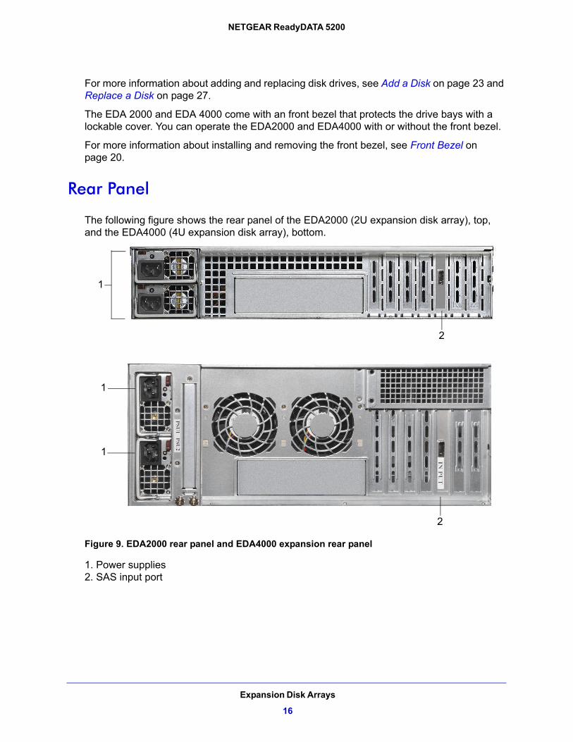
The following figure shows the rear panel of the EDA2000 (2U expansion disk array), top, and the EDA4000 (4U expansion disk array), bottom.
1
1
1
2
2
Figure 9. EDA2000 rear panel and EDA4000 expansion rear panel
1. Power supplies 2. SAS input port
Expansion Disk Arrays
16
NETGEAR ReadyDATA 5200
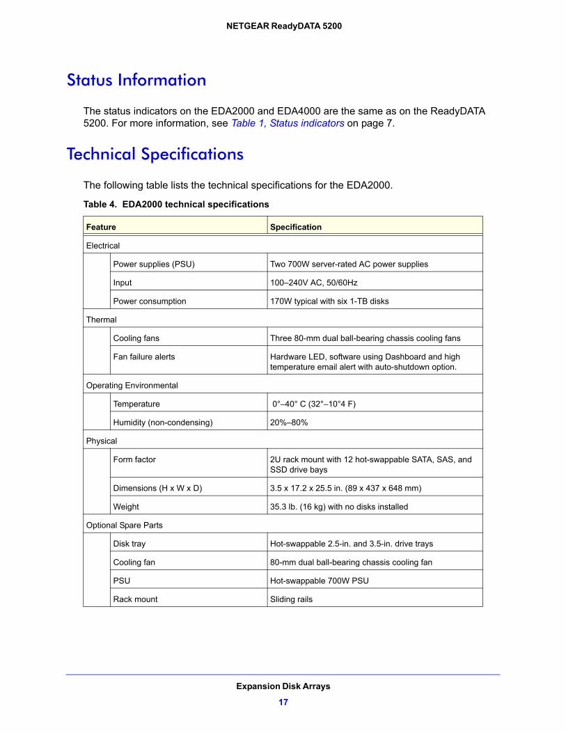
Status Information
The status indicators on the EDA2000 and EDA4000 are the same as on the ReadyDATA 5200. For more information, see Table 1, Status indicators on page 7.
Technical Specifications
The following table lists the technical specifications for the EDA2000.
Table 4. EDA2000 technical specifications
Feature Specification
Electrical
Power supplies (PSU) Two 700W server-rated AC power supplies
Input 100–240V AC, 50/60Hz
Power consumption 170W typical with six 1-TB disks
Thermal
Cooling fans Three 80-mm dual ball-bearing chassis cooling fans
Fan failure alerts Hardware LED, software using Dashboard and high temperature email alert with auto-shutdown option.
Operating Environmental
Temperature 0°–40° C (32°–10°4 F)
Humidity (non-condensing) 20%–80%
Physical
Form factor 2U rack mount with 12 hot-swappable SATA, SAS, and SSD drive bays
Dimensions (H x W x D) 3.5 x 17.2 x 25.5 in. (89 x 437 x 648 mm)
Weight 35.3 lb. (16 kg) with no disks installed
Optional Spare Parts
Disk tray Hot-swappable 2.5-in. and 3.5-in. drive trays
Cooling fan 80-mm dual ball-bearing chassis cooling fan
PSU Hot-swappable 700W PSU
Rack mount Sliding rails
Expansion Disk Arrays
17
NETGEAR ReadyDATA 5200
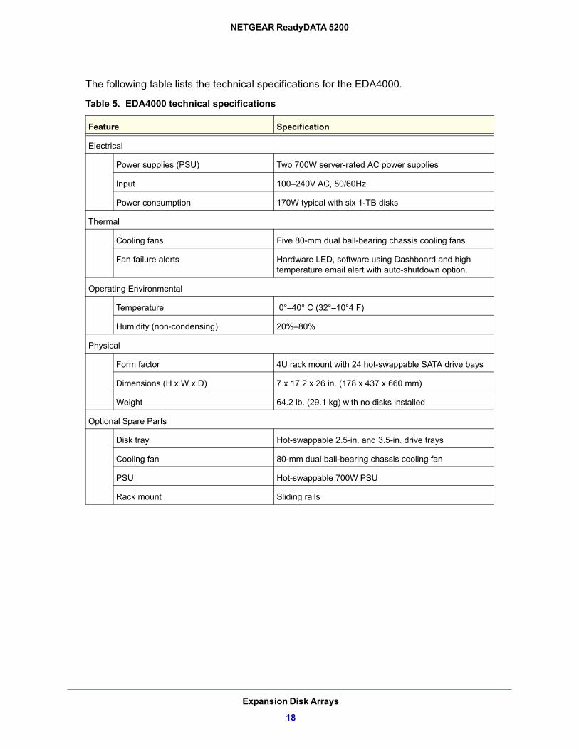
The following table lists the technical specifications for the EDA4000.
Table 5. EDA4000 technical specifications
Feature Specification
Electrical
Power supplies (PSU) Two 700W server-rated AC power supplies
Input 100–240V AC, 50/60Hz
Power consumption 170W typical with six 1-TB disks
Thermal
Cooling fans Five 80-mm dual ball-bearing chassis cooling fans
Fan failure alerts Hardware LED, software using Dashboard and high temperature email alert with auto-shutdown option.
Operating Environmental
Temperature 0°–40° C (32°–10°4 F)
Humidity (non-condensing) 20%–80%
Physical
Form factor 4U rack mount with 24 hot-swappable SATA drive bays
Dimensions (H x W x D) 7 x 17.2 x 26 in. (178 x 437 x 660 mm)
Weight 64.2 lb. (29.1 kg) with no disks installed
Optional Spare Parts
Disk tray Hot-swappable 2.5-in. and 3.5-in. drive trays
Cooling fan 80-mm dual ball-bearing chassis cooling fan
PSU Hot-swappable 700W PSU
Rack mount Sliding rails
Expansion Disk Arrays
18
3
3. MaintenanceThis chapter describes how to perform maintenance activities like adding disks and replacing disks and system components. It includes the following topics:
• Front Bezel
• Disks
• System Components
19
NETGEAR ReadyDATA 5200
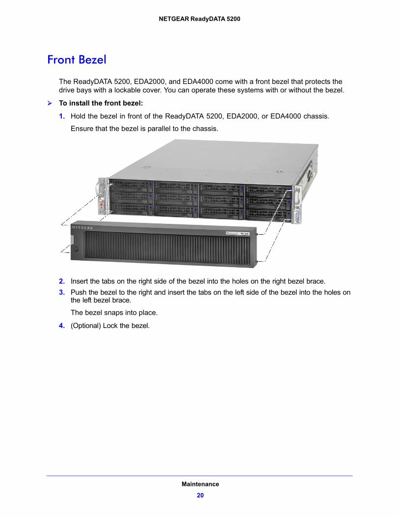
Front Bezel
The ReadyDATA 5200, EDA2000, and EDA4000 come with a front bezel that protects the drive bays with a lockable cover. You can operate these systems with or without the bezel.
To install the front bezel:
1. Hold the bezel in front of the ReadyDATA 5200, EDA2000, or EDA4000 chassis.
Ensure that the bezel is parallel to the chassis.
2. Insert the tabs on the right side of the bezel into the holes on the right bezel brace.
3. Push the bezel to the right and insert the tabs on the left side of the bezel into the holes on the left bezel brace.
The bezel snaps into place.
4. (Optional) Lock the bezel.
Maintenance
20
NETGEAR ReadyDATA 5200
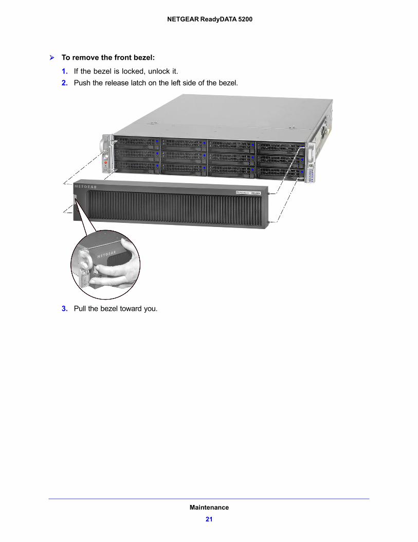
To remove the front bezel:
1. If the bezel is locked, unlock it.
2. Push the release latch on the left side of the bezel.
3. Pull the bezel toward you.
Maintenance
21
NETGEAR ReadyDATA 5200
Disks
The ReadyDATA 5200 does not recognize non-NETGEAR disks. In addition, if you use non-NETGEAR disks, Dashboard might display an error. The ReadyDATA 5200 can recognize only disks that you obtain through NETGEAR or a NETGEAR authorized reseller.
Failed Disk NotificationWhen a disk fails in your ReadyDATA 5200, you are notified by email. Email alerts must be set up for notifications to be sent. In addition, Dashboard provides information about the failed disk.
For information about setting up email alerts and using Dashboard, see the ReadyDATA OS Software Manual, which is available at support.netgear.com.
Each disk bay includes a failed disk LED that illuminates when its disk fails.
If the disk is still under warranty, contact NETGEAR and arrange to have the disk replaced. This process requires that you provide the serial number of the disk. To locate the serial number, open the disk tray and take out the failed disk, or use Dashboard.
WARNING:
No matter how many hard drives are installed in your unit, ensure that all drive trays remain in the drive bays to maintain adequate airflow.
Maintenance
22
NETGEAR ReadyDATA 5200
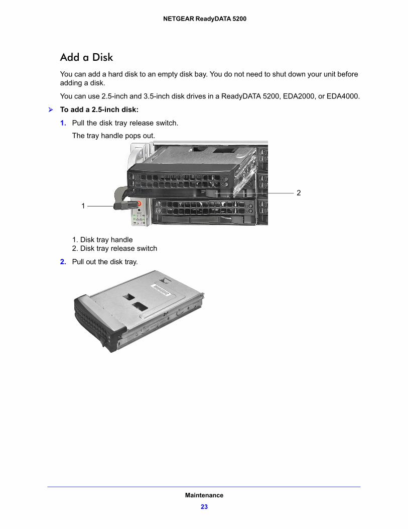
Add a DiskYou can add a hard disk to an empty disk bay. You do not need to shut down your unit before adding a disk.
You can use 2.5-inch and 3.5-inch disk drives in a ReadyDATA 5200, EDA2000, or EDA4000.
To add a 2.5-inch disk:
1. Pull the disk tray release switch.
The tray handle pops out.
1
2
1. Disk tray handle2. Disk tray release switch
2. Pull out the disk tray.
Maintenance
23
NETGEAR ReadyDATA 5200
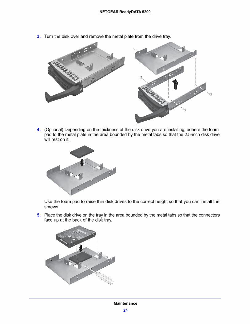
3. Turn the disk over and remove the metal plate from the drive tray.
4. (Optional) Depending on the thickness of the disk drive you are installing, adhere the foam pad to the metal plate in the area bounded by the metal tabs so that the 2.5-inch disk drive will rest on it.
Use the foam pad to raise thin disk drives to the correct height so that you can install the screws.
5. Place the disk drive on the tray in the area bounded by the metal tabs so that the connectors face up at the back of the disk tray.
Maintenance
24
NETGEAR ReadyDATA 5200
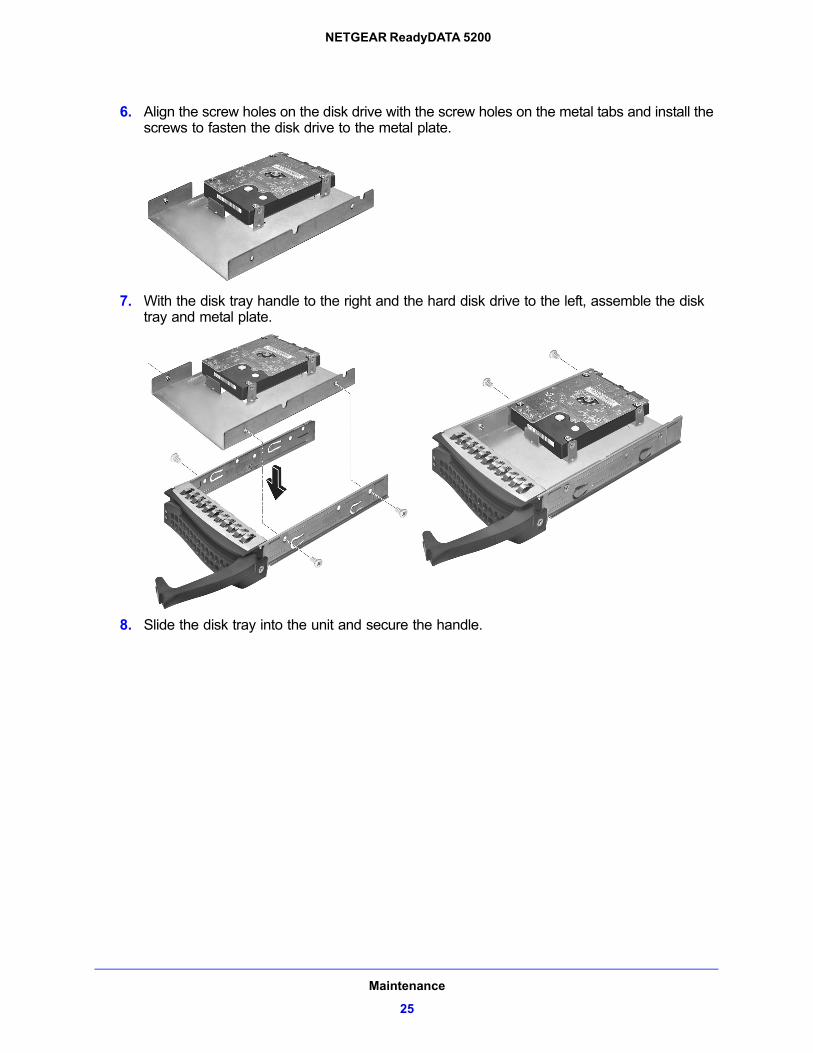
6. Align the screw holes on the disk drive with the screw holes on the metal tabs and install the screws to fasten the disk drive to the metal plate.
7. With the disk tray handle to the right and the hard disk drive to the left, assemble the disk tray and metal plate.
8. Slide the disk tray into the unit and secure the handle.
Maintenance
25
NETGEAR ReadyDATA 5200
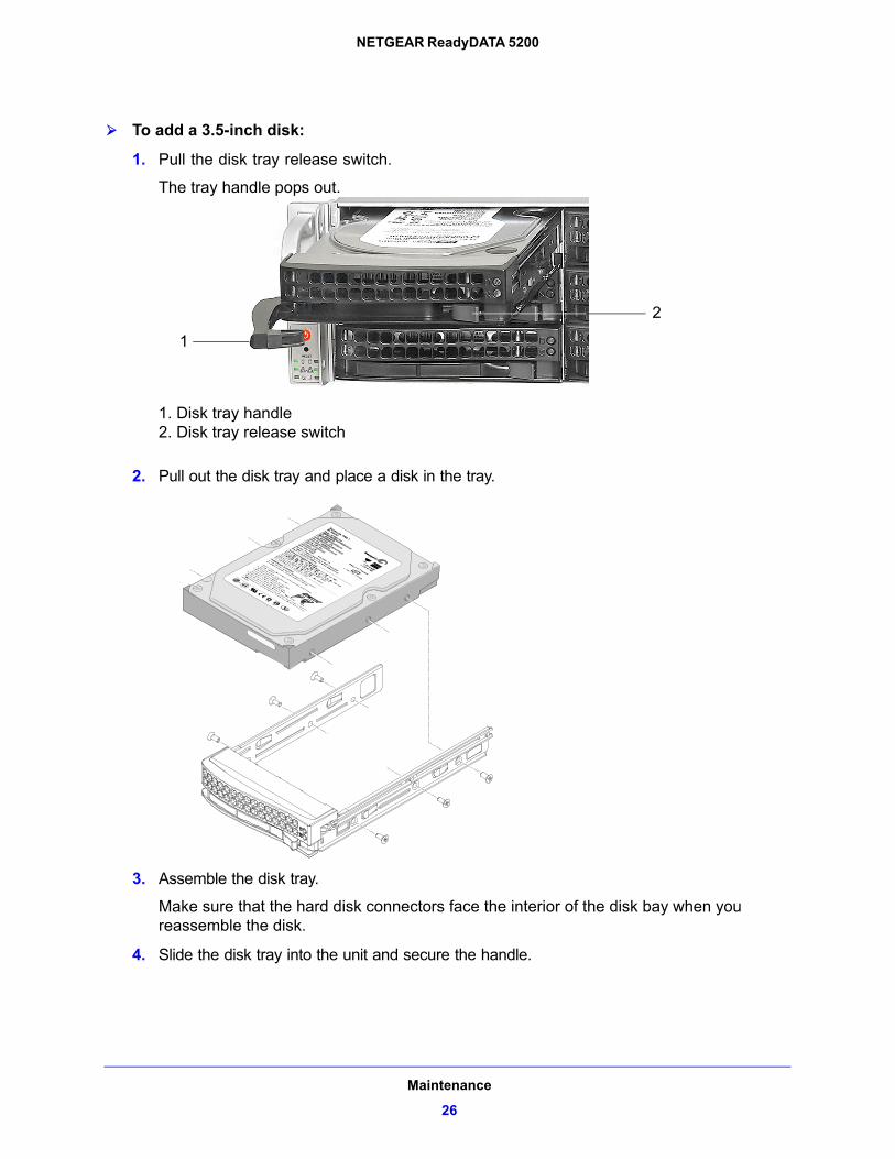
To add a 3.5-inch disk:
1. Pull the disk tray release switch.
The tray handle pops out.
1
2
1. Disk tray handle2. Disk tray release switch
2. Pull out the disk tray and place a disk in the tray.
3. Assemble the disk tray.
Make sure that the hard disk connectors face the interior of the disk bay when you reassemble the disk.
4. Slide the disk tray into the unit and secure the handle.
Maintenance
26
NETGEAR ReadyDATA 5200
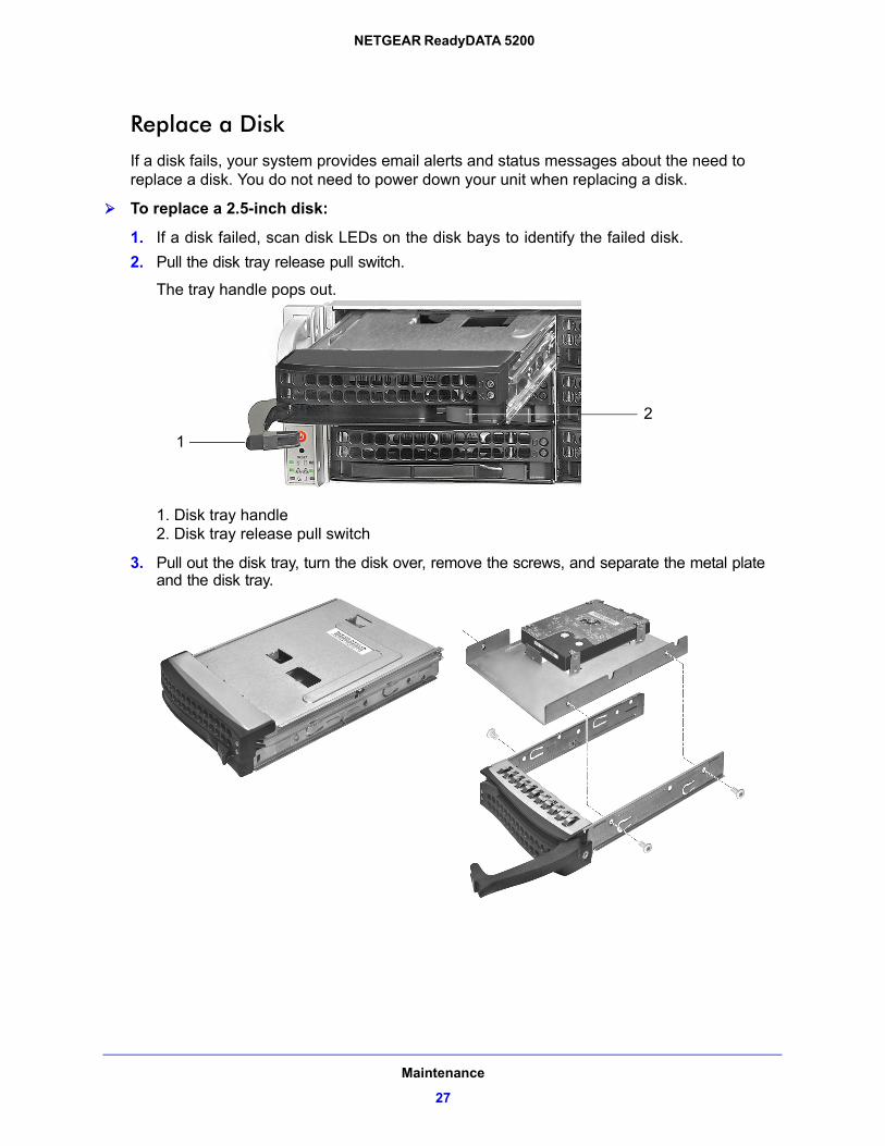
Replace a DiskIf a disk fails, your system provides email alerts and status messages about the need to replace a disk. You do not need to power down your unit when replacing a disk.
To replace a 2.5-inch disk:
1. If a disk failed, scan disk LEDs on the disk bays to identify the failed disk.
2. Pull the disk tray release pull switch.
The tray handle pops out.
1
2
1. Disk tray handle2. Disk tray release pull switch
3. Pull out the disk tray, turn the disk over, remove the screws, and separate the metal plate and the disk tray.
Maintenance
27

NETGEAR ReadyDATA 5200
4. Remove the screws that hold the disk drive to the metal tabs and remove the old disk drive.
5. Replace the disk drive and reassemble the disk tray.
For more information, see Add a Disk on page 23.
6. Slide the disk tray back into the unit and secure the handle.
Maintenance
28
NETGEAR ReadyDATA 5200
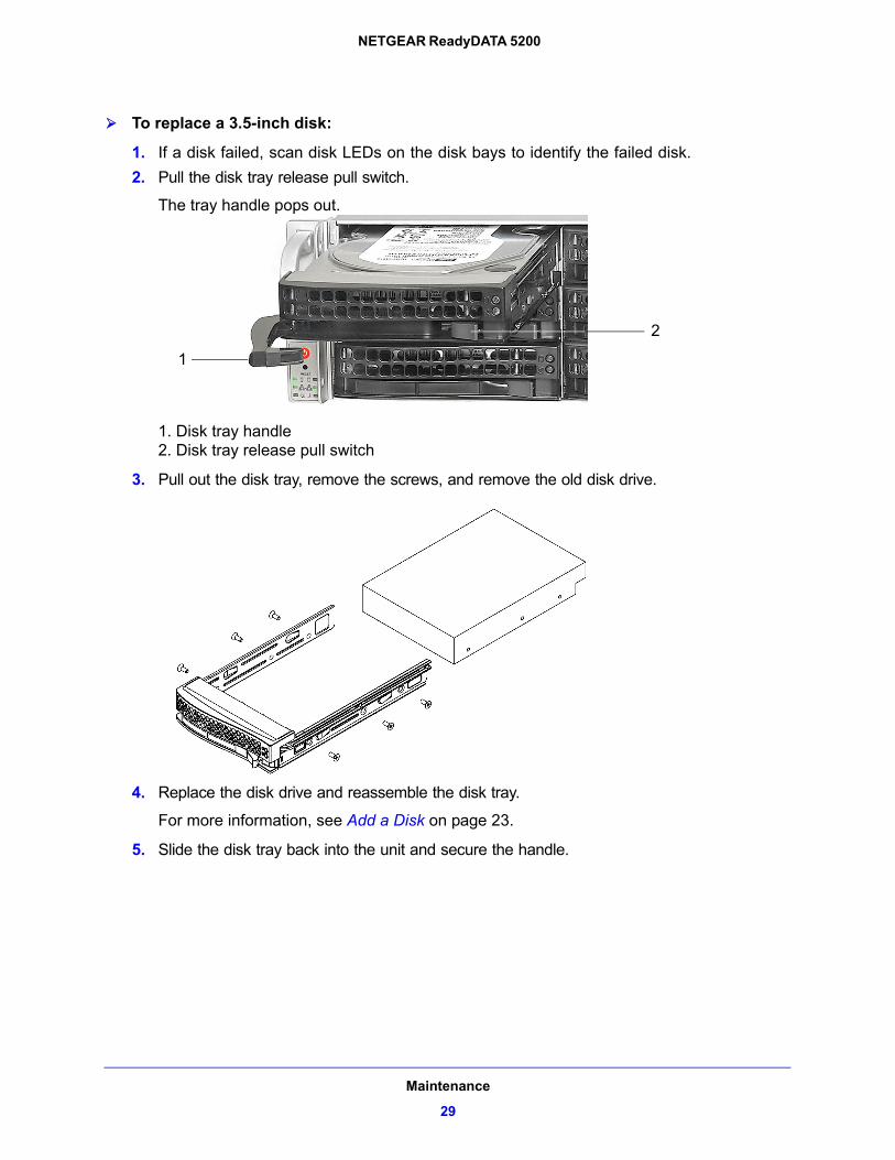
To replace a 3.5-inch disk:
1. If a disk failed, scan disk LEDs on the disk bays to identify the failed disk.
2. Pull the disk tray release pull switch.
The tray handle pops out.
1
2
1. Disk tray handle2. Disk tray release pull switch
3. Pull out the disk tray, remove the screws, and remove the old disk drive.
4. Replace the disk drive and reassemble the disk tray.
For more information, see Add a Disk on page 23.
5. Slide the disk tray back into the unit and secure the handle.
Maintenance
29
NETGEAR ReadyDATA 5200
System Components
You can replace system components on your ReadyDATA 5200, EDA2000, or EDA4000.
Power SupplyIf either of the two power supply modules fails, the other module takes the full load and allows the system to continue operation without interruption. The power diagnostic LED illuminates until the failed unit is replaced.
You do not need to shut down the system to replace a power supply unit. The backup power supply module keeps the system operating while you replace the failed hot-swappable power supply. Replace a failed power supply with the same model.
To replace a power supply:
1. Unplug the AC power cord from the failed power supply module.
2. Depress the locking tab on the power supply module and use the rounded handle to pull it straight out.
3. Push the new power supply unit into the power bay until you hear a click.
4. Secure the locking tab on the unit.
5. Plug the AC power cord back into the unit.
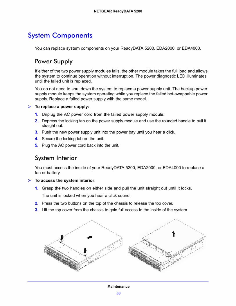
System InteriorYou must access the inside of your ReadyDATA 5200, EDA2000, or EDA4000 to replace a fan or battery.
To access the system interior:
1. Grasp the two handles on either side and pull the unit straight out until it locks.
The unit is locked when you hear a click sound.
2. Press the two buttons on the top of the chassis to release the top cover.
3. Lift the top cover from the chassis to gain full access to the inside of the system.
Maintenance
30
NETGEAR ReadyDATA 5200
WARNING:
Ensure that the chassis cover is in place when the system is operating to allow proper cooling. Out-of-warranty damage to the system can occur if you do not strictly follow this practice.
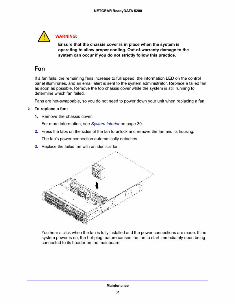
FanIf a fan fails, the remaining fans increase to full speed, the information LED on the control panel illuminates, and an email alert is sent to the system administrator. Replace a failed fan as soon as possible. Remove the top chassis cover while the system is still running to determine which fan failed.
Fans are hot-swappable, so you do not need to power down your unit when replacing a fan.
To replace a fan:
1. Remove the chassis cover.
For more information, see System Interior on page 30.
2. Press the tabs on the sides of the fan to unlock and remove the fan and its housing.
The fan’s power connection automatically detaches.
3. Replace the failed fan with an identical fan.
You hear a click when the fan is fully installed and the power connections are made. If the system power is on, the hot-plug feature causes the fan to start immediately upon being connected to its header on the mainboard.
Maintenance
31
NETGEAR ReadyDATA 5200
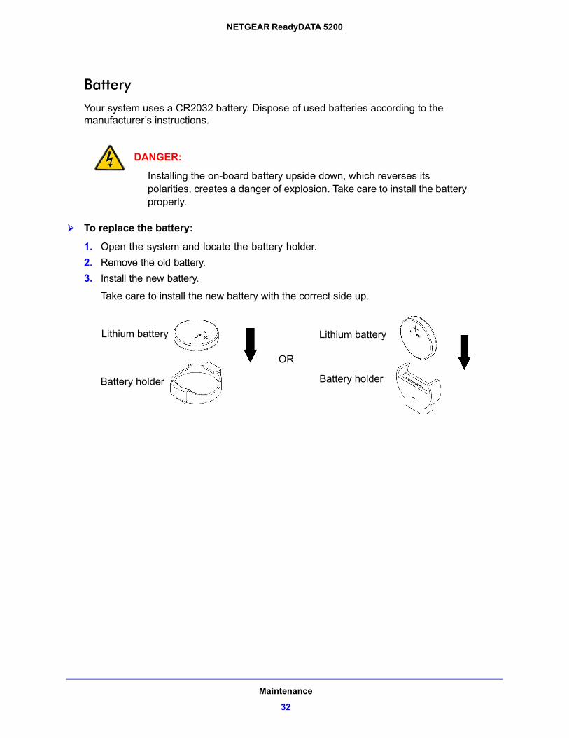
BatteryYour system uses a CR2032 battery. Dispose of used batteries according to the manufacturer’s instructions.
DANGER:
Installing the on-board battery upside down, which reverses its polarities, creates a danger of explosion. Take care to install the battery properly.
To replace the battery:
1. Open the system and locate the battery holder.
2. Remove the old battery.
3. Install the new battery.
Take care to install the new battery with the correct side up.
Lithium battery Lithium battery
Battery holder Battery holder
OR
Maintenance
32
A
A. Warnings and PrecautionsThis appendix contains safety warnings and precautions for the ReadyDATA 5200 . It includes the following sections:
• Safety Warnings
• Electrical Safety Precautions
• General Safety Precautions
• Electrostatic Discharge (ESD) Precautions
33
NETGEAR ReadyDATA 5200
Safety Warnings
1. The equipment is certified for installation only by trained personnel, according to the installation instructions provided with each unit.
2. The socket outlet shall be installed near the equipment and shall be easily accessible. 3. Observe the on-board battery precautions. Follow the battery replacement instructions in
Battery on page 32.
DANGER:
Installing the on-board battery upside down, which reverses its polarities, creates a danger of explosion. Take care to install the battery properly.
4. The units and their associated LAN connections shall be interconnected only with equipment within the same building.
5. Slide or rail-mounted equipment is not to be used as a shelf or a work space.
Electrical Safety Precautions
Follow basic electrical safety precautions to protect yourself from harm and the ReadyDATA 5200 from damage:
• Be aware of the locations of the power on/off switch on the chassis as well as the room’s emergency power-off switch, disconnection switch, or electrical outlet. If an electrical accident occurs, you can then quickly remove power from the system.
• Do not work alone when working with high-voltage components.
• Always disconnect power from the system when removing or installing main system components, such as the main board or memory modules. When disconnecting power, you should first power down the system with the operating system and then unplug the power cords of all the power supply units in the system.
• When working around exposed electrical circuits, another person who is familiar with the power-off controls should be nearby to switch off the power if necessary.
• Use only one hand when working with powered-on electrical equipment. This is to avoid making a complete circuit, which will cause electrical shock. Use extreme caution when using metal tools, which can easily damage any electrical components or circuit boards they come into contact with.
Warnings and Precautions
34
NETGEAR ReadyDATA 5200
• Do not use mats designed to decrease static electrical discharge as protection from electrical shock. Instead, use rubber mats that have been specifically designed as electrical insulators.
• The power supply cords must include a grounding plug and must be plugged into grounded electrical outlets.
General Safety Precautions
Follow these rules to ensure general safety:
• Keep the area around the ReadyDATA 5200 clean and free of clutter.
• The ReadyDATA 5200 weighs approximately 82 pounds when fully loaded. When lifting the system, two people at either end should lift slowly with their feet spread out to distribute the weight. Always keep your back straight and lift with your legs.
• Place the chassis top cover and any system components that have been removed away from the system or on a table so that they will not accidentally be stepped on.
• While working on the system, do not wear loose clothing such as neckties and unbuttoned shirt sleeves, which can come into contact with electrical circuits or be pulled into a cooling fan.
• Remove any jewelry or metal objects from your body, which are excellent metal conductors that can create short circuits and harm you if they come into contact with printed circuit boards or areas where power is present.
• On-board battery: This battery must be replaced only with the same or an equivalent type recommended by the manufacturer. Dispose of used batteries according to the manufacturer’s instructions.
DANGER:
There is a danger of explosion if the on-board battery is installed upside down, which will reverse its polarities.
• Main board replaceable soldered-in fuses: Self-resetting PTC (positive temperature coefficient) fuses on the main board must be replaced by trained service technicians only. The new fuse must be the same as or equivalent to the one replaced. Contact technical support for details and support.
Warnings and Precautions
35
NETGEAR ReadyDATA 5200
Electrostatic Discharge (ESD) Precautions
Electrostatic discharge is generated by two objects with different electrical charges coming into contact with each other. An electrical discharge is created to neutralize this difference, which can damage electronic components and printed circuit boards. The following measures are generally sufficient to neutralize this difference before contact is made to protect your equipment from ESD:
• Use a grounded wrist strap designed to prevent static discharge.
• Keep all components and printed circuit boards (PCBs) in their antistatic bags until ready for use.
• Touch a grounded metal object before removing the board from the antistatic bag.
• Do not let components or PCBs come into contact with your clothing, which might retain a charge even if you are wearing a wrist strap.
• Handle a board by its edges only; do not touch its components, peripheral chips, memory modules, or contacts.
• When handling chips or modules, avoid touching their pins.
• Put the main board and peripherals back into their antistatic bags when not in use.
• For grounding purposes, make sure your computer chassis provides excellent conductivity between the power supply, the case, the mounting fasteners, and the main board.
• After accessing the inside of the system, close the system back up and secure it to the rack unit with the retention screws after ensuring that all connections have been made.
Warnings and Precautions
36

B
B. Notification of ComplianceRegulatory Compliance Information
This section includes user requirements for operating this product in accordance with National laws for usage of radio spectrum and operation of radio devices. Failure of the end-user to comply with the applicable requirements may result in unlawful operation and adverse action against the end-user by the applicable National regulatory authority.
This product’s firmware limits operation to only the channels allowed in a particular Region or Country. Therefore, all options described in this user's guide may not be available in your version of the product.
FCC Requirements for Operation in the United States
FCC Information to User
This product does not contain any user serviceable components and is to be used with approved antennas only. Any product changes or modifications will invalidate all applicable regulatory certifications and approvals
This device complies with Part 15 of the FCC Rules. Operation is subject to the following two conditions: (1) This device may not cause harmful interference, and (2) this device must accept any interference received, including interference that may cause undesired operation.
FCC Guidelines for Human Exposure
This equipment complies with FCC radiation exposure limits set forth for an uncontrolled environment. This equipment should be installed and operated with minimum distance of 20 cm between the radiator and your body.
This transmitter must not be co-located or operating in conjunction with any other antenna or transmitter.
37

NETGEAR ReadyDATA 5200
FCC Declaration Of Conformity
We, NETGEAR, Inc., 350 East Plumeria Drive, San Jose, CA 95134, declare under our sole responsibility that the NETGEAR ReadyDATA 5200 complies with Part 15 of FCC Rules.
Operation is subject to the following two conditions:
• This device may not cause harmful interference, and
• This device must accept any interference received, including interference that may cause undesired operation.
FCC Radio Frequency Interference Warnings & Instructions
This equipment has been tested and found to comply with the limits for a Class A digital device, pursuant to Part 15 of the FCC Rules. These limits are designed to provide reasonable protection against harmful interference in a residential installation. This equipment uses and can radiate radio frequency energy and, if not installed and used in accordance with the instructions, may cause harmful interference to radio communications. However, there is no guarantee that interference will not occur in a particular installation.
If this equipment does cause harmful interference to radio or television reception, which can be determined by turning the equipment off and on, the user is encouraged to try to correct the interference by one or more of the following methods:
• Reorient or relocate the receiving antenna.
• Increase the separation between the equipment and the receiver.
• Connect the equipment into an electrical outlet on a circuit different from that which the radio receiver is connected.
• Consult the dealer or an experienced radio/TV technician for help.
Modifications made to the product, unless expressly approved by NETGEAR, Inc., could void the user's right to operate the equipment.
Canadian Department of Communications Radio Interference Regulations
This digital apparatus, NETGEAR ReadyDATA 5200, the EDA2000, and the EDA4000, do not exceed the Class A limits for radio-noise emissions from digital apparatus as set out in the Radio Interference Regulations of the Canadian Department of Communications.
European Union
The NETGEAR ReadyDATA 5200 complies with essential requirements of EU EMC Directive 2004/108/EC and Low Voltage Directive 2006/95/EC as supported by applying the following test methods and standards:
• EN55022: 2006 / A1: 2007
• EN55024: 1998 / A1: 2001 / A2 : 2003
• EN60950-1: 2005 2nd Edition
• EN 61000-3-2:2006
• EN 61000-3-3:1995 w/A1: 2001+A2: 2005
Notification of Compliance
38