Reading International Journal of Computational Methods
18
International Journal of Computational Methods (2020) 2041015 (18 pages) c World Scientific Publishing Company DOI: 10.1142/S0219876220410157 Numerical Simulation of Viscous Flows Around a Surface Combatant Model at Different Drift Angles Using Overset Grids Jianhua Wang, Zhenghao Liu and Decheng Wan ∗ Computational Marine Hydrodynamics Lab (CMHL) State Key Laboratory of Ocean Engineering School of Naval Architecture, Ocean and Civil Engineering Shanghai Jiao Tong University, Shanghai, P. R. China ∗ [email protected] Received 21 December 2016 Accepted 7 August 2020 Published 19 December 2020 Viscous flows around ship hull is of great complexity, and when the ship is advancing with drift angles, the flow field can be more complicated. In this paper, the viscous flow field around an obliquely towed surface combatant DTMB 5512 is computed using the unsteady Reynolds-averaged Navier–Stokes (URANS) method. The numerical simula- tions are carried out by the in-house CFD solver naoe-FOAM-SJTU, which is developed on the open source platform OpenFOAM. To refine local grids and simulate dynamic ship motions, the overset grid approach is applied. Grid convergence study is first per- formed at straight-ahead towed condition with three sets of grid number and the results show monotonically convergence. Six different drift angles for the DTMB 5512 model at Froude number of 0.28 are simulated and the predicted hydrodynamic forces and flow field are presented. During the simulation, the ship hull is free to trim and sinkage at a free surface environment. As for straight-ahead towed condition, the total resistance coefficient and flow field, i.e., wave pattern and wake region, between this work and the experiment are compared. Both force coefficients and flow field show good agree- ment with the available experimental data. For oblique towed conditions, the lateral force, yaw moment and the derived hydrodynamic derivatives are also presented and compared with the experimental results. The variation of wave pattern and wake region at different drift angles are presented and analyzed. The results show that the current approach can be an effective tool to predict the viscous flows and hydrodynamic loads for oblique towed ships. Keywords : Surface combatant; naoe-FOAM-SJTU solver; viscous flow field; overset grid; drift angle. ∗ Corresponding author. 2041015-1 Int. J. Comput. Methods Downloaded from www.worldscientific.com by KP Teng on 02/24/21. Re-use and distribution is strictly not permitted, except for Open Access articles.
Transcript of Reading International Journal of Computational Methods

2nd Reading
December 18, 2020 16:44 WSPC/0219-8762 196-IJCM 2041015
International Journal of Computational Methods(2020) 2041015 (18 pages)c© World Scientific Publishing CompanyDOI: 10.1142/S0219876220410157
Numerical Simulation of Viscous Flows Around a SurfaceCombatant Model at Different Drift Angles
Using Overset Grids
Jianhua Wang, Zhenghao Liu and Decheng Wan∗
Computational Marine Hydrodynamics Lab (CMHL)State Key Laboratory of Ocean Engineering
School of Naval Architecture, Ocean and Civil EngineeringShanghai Jiao Tong University, Shanghai, P. R. China
Received 21 December 2016Accepted 7 August 2020
Published 19 December 2020
Viscous flows around ship hull is of great complexity, and when the ship is advancingwith drift angles, the flow field can be more complicated. In this paper, the viscous flowfield around an obliquely towed surface combatant DTMB 5512 is computed using theunsteady Reynolds-averaged Navier–Stokes (URANS) method. The numerical simula-tions are carried out by the in-house CFD solver naoe-FOAM-SJTU, which is developedon the open source platform OpenFOAM. To refine local grids and simulate dynamicship motions, the overset grid approach is applied. Grid convergence study is first per-formed at straight-ahead towed condition with three sets of grid number and the results
show monotonically convergence. Six different drift angles for the DTMB 5512 model atFroude number of 0.28 are simulated and the predicted hydrodynamic forces and flowfield are presented. During the simulation, the ship hull is free to trim and sinkage ata free surface environment. As for straight-ahead towed condition, the total resistancecoefficient and flow field, i.e., wave pattern and wake region, between this work andthe experiment are compared. Both force coefficients and flow field show good agree-ment with the available experimental data. For oblique towed conditions, the lateralforce, yaw moment and the derived hydrodynamic derivatives are also presented andcompared with the experimental results. The variation of wave pattern and wake regionat different drift angles are presented and analyzed. The results show that the currentapproach can be an effective tool to predict the viscous flows and hydrodynamic loadsfor oblique towed ships.
Keywords: Surface combatant; naoe-FOAM-SJTU solver; viscous flow field; overset grid;drift angle.
∗Corresponding author.
2041015-1
Int.
J. C
ompu
t. M
etho
ds D
ownl
oade
d fr
om w
ww
.wor
ldsc
ient
ific
.com
by K
P T
eng
on 0
2/24
/21.
Re-
use
and
dist
ribu
tion
is s
tric
tly n
ot p
erm
itted
, exc
ept f
or O
pen
Acc
ess
artic
les.

2nd Reading
December 18, 2020 16:44 WSPC/0219-8762 196-IJCM 2041015
J. Wang, Z. Liu & D. Wan
1. Introduction
Good maneuvering behavior of a ship is essential to keep its navigational safety.In the last few decades, several standards have been developed by the Interna-tional Maritime Organization (IMO) for ship maneuverability. The hydrodynamicperformance acting on an advancing ship with drift angles is of paramount impor-tance in the ship maneuverability. As we know, when a ship is traveling with driftangles, the lateral forces as well as yaw moments acting on the hull will push theship sideways. The effect of drift angle has significant influence on ship resistance,propulsion, maneuverability and stability. Thus, it is essential to investigate the flowcharacteristics around ship hull at different drift angles to better understand thehydrodynamic performance. Up to now, many researchers have studied the hydro-dynamic performance and flow field of different types of oblique towed vessels.
Previous investigations are mostly relied on model tests, where static anddynamic planar motion mechanism (PMM) tests are commonly applied. These testscan be feasible in motion generation using a PMM motion generator in towing tank.Egeberg et al. [2014] investigated the vortices of a surface combatant for staticdrift angles 0◦, 10◦ and 20◦ by means of tomographic particle image velocimetry(TPIV) system in a towing tank. However, there are still some obvious deficienciesin model test. The complexity of experimental settings can lead to time consumingand expensive to predict hydrodynamic performance. In addition, there are limita-tions in obtaining physical understanding of flow field around a ship in model tests,especially for the oblique towed condition.
Numerical simulation methods based on Computational Fluid Dynamics (CFD)for ship maneuverability significantly contribute to resolve the problems. Stern et al.[2011] gave an overview of the benchmark cases for the prediction capabilities ofdifferent ship maneuver simulation methods for typical tanker, container, and com-batant hulls. Bhushan et al. [2009] investigated flow field of a fully appended DTMB5415 at both model scale and full scale using unsteady Reynolds-averaged Navier–Stokes (URANS) method with different wall functions. Wang et al. [2011] com-puted viscous flow around KVLCC2 model using FLUENT, their numerical resultsagreed well with experimental data in static oblique towed conditions. Hajivand andMousavizadegan [2015] carried out a numerical maneuvering oblique towed test fora DTMB 5512 model in OpenFOAM. The obtained linear and nonlinear velocitydependent damping coefficients showed good agreement with available experimentaldata. Detailed validation of the complex free surface flow around a surface combat-ant DTMB5415 at 20◦ static drift condition were presented by Visonneau et al.[2015] using ISIS-CFD flow solver.
The overset grid approach, composed of blocks of overlapping grids which canmove independently, makes it possible to conduct the computation of complexmotions. The overset grid approach has been applied to the computation of staticand dynamic maneuvers. Using the URANS method with dynamic overset grid tech-nology, Carrica et al. [2013] presented numerical results of steady turn and zigzag
2041015-2
Int.
J. C
ompu
t. M
etho
ds D
ownl
oade
d fr
om w
ww
.wor
ldsc
ient
ific
.com
by K
P T
eng
on 0
2/24
/21.
Re-
use
and
dist
ribu
tion
is s
tric
tly n
ot p
erm
itted
, exc
ept f
or O
pen
Acc
ess
artic
les.

2nd Reading
December 18, 2020 16:44 WSPC/0219-8762 196-IJCM 2041015
Numerical Simulation of Viscous Flows Around a Surface Combatant Model
for a surface combatant at both model and full scale, which indicated that URANSapproach with overset grid technology are feasible for ship maneuvering simula-tion. Sakamoto et al. [2012a, 2012b] performed URANS simulations of the barehull DTMB 5415 model using the CFD code Ship-Iowa Ver. 4, where the dynamicoverset grid method was implemented. Verification and validation for the forces,moments and hydrodynamic derivatives acting on the hull and local flow charac-teristics were presented. Meng and Wan [2016] investigated the effect of drift angleon viscous flow and hydrodynamical forces of KVLCC2M ship model in both deepand shallow water using overset grid method.
The objective of this work is to investigate hydrodynamic performance and vis-cous flow field of the DTMB 5512 model at different drift angles. In this paper, thein-house CFD solver naoe-FOAM-SJTU is developed by implementing overset gridtechnique into the open source code OpenFOAM. An external program Suggar++[Noack et al. (2009)] is used to obtain the grid connectivity among multiple oversetcomponent grids. The numerical results of the hydrodynamic forces, moments andthe hydrodynamic derivatives are presented and compared with experiments per-formed by Gui et al. [2001a, 2001b]. The physical experiment is carried out by astatic PMM system to measure the hydrodynamic loads acting on the hull model.The details information of flow field around ship hull will be given and comparedwith the available experiment results, which shows that the current approach can bean alternative tool to predict the viscous flow and hydrodynamic loads for obliquetowed ships.
2. Numerical Methods
2.1. naoe-FOAM-SJTU solver
The CFD solver naoe-FOAM-SJTU is developed for computing viscous flows aroundships and ocean structures [Cao and Wan (2014); Shen et al. (2014, 2015); Shen andWan (2014); Wang et al. (2015, 2016, 2019)], and mainly composed of a dynamicoverset grid module, a 6DoF motion module, a velocity inlet wave-making moduleand a mooring system module. The CFD solver naoe-FOAM-SJTU solves Navier–Stokes equations for unsteady turbulent flows with VOF method capturing freesurface around the ship hull [Wang et al. (2017, 2018)].
The URANS equations are adopted to address the unsteady incompressible vis-cous flow in naoe-FOAM-SJTU solver. The Navier–Stokes equations can be statedas the continuity and the momentum equations, which are listed as follows:
∇ ·U = 0, (1)
∂ρU∂t
+ ∇(ρ(U − Ug)U) = −∇pd − g · x∇ρ
+∇ · (μeff∇U) + (∇U) · ∇μeff + fσ, (2)
2041015-3
Int.
J. C
ompu
t. M
etho
ds D
ownl
oade
d fr
om w
ww
.wor
ldsc
ient
ific
.com
by K
P T
eng
on 0
2/24
/21.
Re-
use
and
dist
ribu
tion
is s
tric
tly n
ot p
erm
itted
, exc
ept f
or O
pen
Acc
ess
artic
les.

2nd Reading
December 18, 2020 16:44 WSPC/0219-8762 196-IJCM 2041015
J. Wang, Z. Liu & D. Wan
where U and Ug are the velocity field and the velocity of grid nodes, respectively.pd = p − ρg · x is the dynamic pressure and p is the total pressure, ρ is the mixeddensity with water and air. μeff = ρ(ν − νt) is the effective dynamic viscosity, inwhich ν and νt are kinematic viscosity and eddy viscosity, respectively. fσ is thesurface tension caused by the free surface.
The free surface is captured by VOF method [Hirt and Nichols (1981)] withartificial bounded compression techniques. Each of the two phase in VOF methodis considered to have a separately defined volume fraction (α), and the volumefraction function can be determined by solving a transport equation:
∂α
∂t+ ∇ · (αU) + ∇ · [α(1 − α)U r] = 0. (3)
Different phases are marked with volume fraction α, which indicates the relativeproportion of fluid in each cell and its value is always between zero and one atinterface. ⎧⎪⎪⎨
⎪⎪⎩α = 0 air,
0 < α < 1 interface,
α = 1 water.
(4)
Van Leer scheme is applied for VOF equation in OpenFOAM. The RANS andVOF transport equations are discretized by finite volume method (FVM). ThePIMPLE algorithm is used to solve the coupled equation of velocity and pressure.The convection terms are solved by a second-order TVD limited linear scheme, andthe diffusion terms are approximated by a second-order central difference scheme.
2.2. Overset grid approach
An overset grid system is composed of blocks of overlapping grids which can moveindependently without any constraints. Every grid cell in the computational domaincan be marked as fringe, hole or donor. The information of cell types is storedin the domain connectivity information (DCI), which is generated by Suggar++utility. Suggar++ is capable of providing DCI for node-centered and cell-centeredsolvers, and can handle structured and unstructured grids. Since OpenFOAM storesinformation at cell centers and is discretized with unstructured grids, this makesSuggar++ a good candidate for implementation of overset grids.
With the overset grid capability, a full 6DoF motion module with a hierarchyof bodies is implemented, which allows the ship and its appendages to move simul-taneously. This module includes two coordinate systems: one is earth-fixed systemand the other is ship-fixed system. The earth-fixed system can be fixed to earthor move at a constant speed respect to the ship. The ship-fixed system is fixed tothe ship and translates and rotates according to the ship motions. At the initialcondition, the two systems are parallel. With the movement of ship, the solver cal-culates the forces and moments in the earth-fixed system and then transforms them
2041015-4
Int.
J. C
ompu
t. M
etho
ds D
ownl
oade
d fr
om w
ww
.wor
ldsc
ient
ific
.com
by K
P T
eng
on 0
2/24
/21.
Re-
use
and
dist
ribu
tion
is s
tric
tly n
ot p
erm
itted
, exc
ept f
or O
pen
Acc
ess
artic
les.

2nd Reading
December 18, 2020 16:44 WSPC/0219-8762 196-IJCM 2041015
Numerical Simulation of Viscous Flows Around a Surface Combatant Model
to ship-fixed system. Details of the 6DoF module with overset grid technique canbe found in Shen et al. [2015].
3. Geometry and Test Conditions
3.1. Geometry
In this work, the bare hull surface combatant DTMB 5512 model was applied tostudy the effect of drift angle on viscous flow and ship hydrodynamics. Static towedmodel tests for bare hull DTMB 5512 were carried out in the towing tank by IowaInstitute of Hydraulic Research (IIHR). The scale factor is 1:46.588. The geometryof the DTMB 5512 model is shown in Fig. 1 with main particulars of the DTMB5512 hull at both full scale and model scale, as shown in Table 1. In order to obtaina mesh with good quality, the sides of hull deck and stern plate are rounded off.
As mentioned in numerical methods part, two coordinate systems are used tosolve the 6DoF equations. One is earth-fixed system and the other is ship-fixedsystem. Figure 2 describes the coordinate systems utilized for the present simu-lations. In the figure, Xs, Ys denote the XY-plane in the ship-fixed system, andXe, Ye denote the XY-plane in the earth-fixed system. The positive direction of Xe
towards to the aft perpendicular and the positive direction of the Ye is from portto starboard. In this way, the direction of the ship rotation is in clockwise sensewith the right-handed coordinate system. During static oblique towed condition,the model is towed at a constant velocity U with the initial drift angle β relativeto the ship’s axis.
Fig. 1. Geometry of DTMB 5512 model.
Table 1. Main dimensions and particulars.
Main features Symbol Full scale Model scale
Scale ratio λ 1 46.588Length between perpendiculars Lpp (m) 142.00 3.048Length of waterline Lwl (m) 142.1 3.052Breadth B (m) 19.06 0.409Draught T (m) 6.150 0.132Displacement Δ (kg) 84,244,000 82.600
Wetted surface S (m2) 2972.6 1.380Longitudinal center of gravity LCG (m) 70.34 1.539Vertical center of gravity KG (m) 5.582 0.120Longitudinal inertia radius Kyy (m) 35.50 0.777Transverse inertia radius Kxx (m) 7.052 0.131Metacentric height GM(m) 1.950 0.096
2041015-5
Int.
J. C
ompu
t. M
etho
ds D
ownl
oade
d fr
om w
ww
.wor
ldsc
ient
ific
.com
by K
P T
eng
on 0
2/24
/21.
Re-
use
and
dist
ribu
tion
is s
tric
tly n
ot p
erm
itted
, exc
ept f
or O
pen
Acc
ess
artic
les.

2nd Reading
December 18, 2020 16:44 WSPC/0219-8762 196-IJCM 2041015
J. Wang, Z. Liu & D. Wan
Fig. 2. Coordinate systems of static simulations.
3.2. Mesh generation
In this paper, the dynamic overset grid approach is applied for the decomposi-tion of the computational grids, which include two parts, i.e., the background gridand the grid around ship hull. Overlapping areas between the two parts can moveindependently without restrictions. Connections between the two parts are built byinterpolation at appropriate cells or points. Figure 3 shows the arrangement of thecomputational domain. The background domain extends to −1.5Lpp < x < 5.0Lpp,−1.5Lpp < y < 1.5Lpp, −1.0Lpp < z < 0.5Lpp, and the hull domain is muchsmaller with a range of −0.2Lpp < x < 1.2Lpp, −0.2Lpp < y < 0.2Lpp,−0.1Lpp < z < 0.1Lpp. The boundary conditions are as following: At the inlet,fixed value condition, Dirichlet condition is adopted. At the outlet, zero Gradientcondition is applied for both velocity and pressure. The farfield is set as symmetry
Fig. 3. Computational domain.
2041015-6
Int.
J. C
ompu
t. M
etho
ds D
ownl
oade
d fr
om w
ww
.wor
ldsc
ient
ific
.com
by K
P T
eng
on 0
2/24
/21.
Re-
use
and
dist
ribu
tion
is s
tric
tly n
ot p
erm
itted
, exc
ept f
or O
pen
Acc
ess
artic
les.
2nd Reading
December 18, 2020 16:44 WSPC/0219-8762 196-IJCM 2041015
Numerical Simulation of Viscous Flows Around a Surface Combatant Model
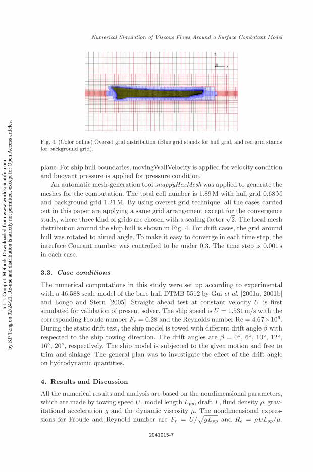
Fig. 4. (Color online) Overset grid distribution (Blue grid stands for hull grid, and red grid standsfor background grid).
plane. For ship hull boundaries, movingWallVelocity is applied for velocity conditionand buoyant pressure is applied for pressure condition.
An automatic mesh-generation tool snappyHexMesh was applied to generate themeshes for the computation. The total cell number is 1.89M with hull grid 0.68Mand background grid 1.21M. By using overset grid technique, all the cases carriedout in this paper are applying a same grid arrangement except for the convergencestudy, where three kind of grids are chosen with a scaling factor
√2. The local mesh
distribution around the ship hull is shown in Fig. 4. For drift cases, the grid aroundhull was rotated to aimed angle. To make it easy to converge in each time step, theinterface Courant number was controlled to be under 0.3. The time step is 0.001 sin each case.
3.3. Case conditions
The numerical computations in this study were set up according to experimentalwith a 46.588 scale model of the bare hull DTMB 5512 by Gui et al. [2001a, 2001b]and Longo and Stern [2005]. Straight-ahead test at constant velocity U is firstsimulated for validation of present solver. The ship speed is U = 1.531m/s with thecorresponding Froude number Fr = 0.28 and the Reynolds number Re = 4.67×10⁶.During the static drift test, the ship model is towed with different drift angle β withrespected to the ship towing direction. The drift angles are β = 0◦, 6◦, 10◦, 12◦,16◦, 20◦, respectively. The ship model is subjected to the given motion and free totrim and sinkage. The general plan was to investigate the effect of the drift angleon hydrodynamic quantities.
4. Results and Discussion
All the numerical results and analysis are based on the nondimensional parameters,which are made by towing speed U , model length Lpp, draft T , fluid density ρ, grav-itational acceleration g and the dynamic viscosity μ. The nondimensional expres-sions for Froude and Reynold number are Fr = U/
√gLpp and Re = ρULpp/μ.
2041015-7
Int.
J. C
ompu
t. M
etho
ds D
ownl
oade
d fr
om w
ww
.wor
ldsc
ient
ific
.com
by K
P T
eng
on 0
2/24
/21.
Re-
use
and
dist
ribu
tion
is s
tric
tly n
ot p
erm
itted
, exc
ept f
or O
pen
Acc
ess
artic
les.

2nd Reading
December 18, 2020 16:44 WSPC/0219-8762 196-IJCM 2041015
J. Wang, Z. Liu & D. Wan
Other nondimensional forms of v′, v′, r′, r′, X ′, Y ′, N ′ are as follows:
⎡⎣v′
v′
⎤⎦ =
⎡⎢⎢⎣
v
U
v
U
⎤⎥⎥⎦, (5)
[r′
r′
]=
⎡⎢⎢⎢⎣
rLpp
U
r
(Lpp
U
)2
⎤⎥⎥⎥⎦, (6)
⎡⎢⎢⎣X ′
Y ′
N ′
⎤⎥⎥⎦ =
⎡⎢⎢⎢⎢⎢⎢⎢⎢⎣
X
0.5ρU2TLpp
Y
0.5ρU2TLpp
N
0.5ρU2TL2pp
⎤⎥⎥⎥⎥⎥⎥⎥⎥⎦
. (7)
In this study, the hydrodynamic forces and moments in Eq. (7) are very importantfor further analysis. According to Maneuvering Modeling Group (MMG) model,the forces and moment coefficients in ship-fixed system of the bare hull model aredescribed as follows:
⎡⎢⎢⎣X ′
Y ′
N ′
⎤⎥⎥⎦ =
⎡⎢⎢⎢⎢⎢⎢⎢⎣
X∗ + Xvvv′2 + Xrrr
′2 + Xvrv′r′
Yv v′ + Yr r′ + Yvv′ + Yv|v|v′|v′| + Yrr
′ + Yr|r|r′|r′|+ Y|v|r|v′|r′ + Yv|r|v′|r′|
Nvv′ + Nr r
′ + Nvv′ + Nv|v|v′|v′| + Nrr′ + Nr|r|r′|r′|
+ N|v|r|v′|r′ + Nv|r|v′|r′|
⎤⎥⎥⎥⎥⎥⎥⎥⎦. (8)
For the static drift tests, the ship model has no angular velocity r and the forcesand moment coefficients on the right hand of Eq. (8) can be simplified as follows:⎡
⎢⎢⎣X ′
Y ′
N ′
⎤⎥⎥⎦ =
⎡⎢⎢⎣
X∗ + Xvvv′2
Yvv′ + Yv|v|v′|v′|Nvv
′ + Nv|v|v′|v′|
⎤⎥⎥⎦, (9)
where X∗ is the towing force with no drift angle.
4.1. Grid convergence study
Grid convergence study is a straight and consistent way to determine the magni-tude of discretization error in numerical simulation. In this paper, grid convergenceexaminations are performed for the cases of the straight-ahead towed condition.This study is also necessary for the numerical computation and determine which
2041015-8
Int.
J. C
ompu
t. M
etho
ds D
ownl
oade
d fr
om w
ww
.wor
ldsc
ient
ific
.com
by K
P T
eng
on 0
2/24
/21.
Re-
use
and
dist
ribu
tion
is s
tric
tly n
ot p
erm
itted
, exc
ept f
or O
pen
Acc
ess
artic
les.

2nd Reading
December 18, 2020 16:44 WSPC/0219-8762 196-IJCM 2041015
Numerical Simulation of Viscous Flows Around a Surface Combatant Model
grid is suitable for the simulation. All grids used in this paper are unstructuredof which systematic refinement in three directions is difficult. In order to achieveconsistent refinement in all directions, the following approach is applied. Snappy-HexMesh requires a preliminary Cartesian grid and splits cells from it to get anunstructured mesh. By creating systematically refined Cartesian grids with a spe-cific refinement ratio and running SnappyHexMesh over these grids, the resultingunstructured grids are approximately systematically refined as required. Accord-ing to the experiments, the errors arising from extrapolation can be reduced if therefinement ratio of r > 1.3 [Hajivand and Mousavizadegan (2015)]. In this study, arefinement ratio of r =
√2 in each direction is selected. The number of meshes and
calculated nondimensional force coefficients are shown in Table 2.Stern et al. [2006] proposed a verification method to estimating uncertainty due
to grid and time step errors. The convergence solution (RG) of different solutions(Si) is defined as follows:
RG =S2 − S1
S3 − S2, (10)
where Si corresponds to solutions with fine, medium and coarse grid, respectively.Different RG values represent different convergence conditions: (1) 0 < RG < 1represents monotonic convergence, and generalized Richardson extrapolation (RE)is used to estimate grid uncertainty. (2) RG < 0 represents oscillatory convergence,and uncertainties can be estimated by attempting to bound the error based onoscillation maximums SU and minimums SL. (3) RG > 1 represents divergence,and uncertainties cannot be estimated. The grid convergence study is conducted atFr = 0.28 with three sets of grid number ranging from 0.64 million to 3.67 million.The results show good convergence, as summarized in Table 2. As the grid is refined,the total resistance coefficient approaches the experimental data monotonically.Thus, the RE method is used to estimate convergence rate in this study [Roache(1994)]. Order of discretization is estimated as follows:
P =ln(1/RG)
ln(r), (11)
Table 2. Grid convergence study.
Grid ID Grid size Cp Cv Ct Error of Ct
EFD 1.706 × 10⁻²
Fine S1 3.67M 0.507 × 10⁻² 1.171 × 10⁻² 1.678 × 10⁻² −1.66%
Medium S2 1.87M 0.499 × 10⁻² 1.162 × 10⁻² 1.661 × 10⁻² −2.64%Coarse S3 0.64M 0.473 × 10⁻² 1.124 × 10⁻² 1.597 × 10⁻² −6.39%RG 0.307 0.237 0.265P 3.4088 4.1559 3.834GCI12 0.87% 0.31% 0.45%GCI23 2.88% 1.27% 1.74%Convergence type Monotonic Monotonic Monotonic
2041015-9
Int.
J. C
ompu
t. M
etho
ds D
ownl
oade
d fr
om w
ww
.wor
ldsc
ient
ific
.com
by K
P T
eng
on 0
2/24
/21.
Re-
use
and
dist
ribu
tion
is s
tric
tly n
ot p
erm
itted
, exc
ept f
or O
pen
Acc
ess
artic
les.
2nd Reading
December 18, 2020 16:44 WSPC/0219-8762 196-IJCM 2041015
J. Wang, Z. Liu & D. Wan
then, Grid Convergence Index (GCI) is defined as follows:
GCIij = FS|eij |
rp − 1, (12)
where FS is a safety factor, and for convergence study with minimum three gridsor more, FS = 1.25 according to Roache [1994], eij is the error between Si and Sj .The GCI can indicate the error using different grids. Small value of GCI means thesolution is accurate relatively. Table 2 shows the GCI values of different hydrody-namic force coefficients. All coefficients show monotonic convergence with RG of0.307, 0.237 and 0.265, respectively. The GCI12 (between fine and medium) of thetotal resistance coefficient Ct is only 0.45%, which can illustrate that grid densityhas limited effect on resistance in fine and medium grid. The GCI of Cp showsthe maximum values. It is obvious that the values of GCI23 (between medium andcoarse) are larger than those of GCI12 and the error of Ct between coarse grid andexperimental results is much larger than that of medium and fine grid. The griduncertainty between the simulation results of fine grid and medium grid is under 1%,but the computational time is significantly increased. Therefore, the medium gridis selected in our following numerical computations of obliquely towed conditions.
4.2. Straight-ahead case and validation
For the calculation of straight-ahead case, comparisons were made with the exper-iments performed by Gui et al. [2001a, 2001b]. The force coefficients are defined asfollows:
⎡⎢⎢⎣
Ct
Cv
Cp
⎤⎥⎥⎦ =
⎡⎢⎢⎢⎢⎢⎢⎢⎢⎣
RT
0.5ρU2TLpp
RV
0.5ρU2TLpp
RP
0.5ρU2TL2pp
⎤⎥⎥⎥⎥⎥⎥⎥⎥⎦, (13)
where ρ is fluid density, TLpp is lateral underwater area and U is the ship speed. Asshown in Table 3, the total resistance coefficient Ct of CFD and EFD is 1.661×10⁻²
and 1.706 × 10⁻², respectively. The predicted result is underestimated by 2.64%,which indicates that the present approach can give accurate prediction of the shipresistance. Predicted motion is also presented in Table 3. The errors of predictedsinkage and trim are 0.75% and 5.96%, respectively.
Furthermore, CFD approach cannot only give the prediction of ship motions andforces, but also the whole flow information around the ship hull. The predicted wavepattern and wake field are presented and compared with the experiment measure-ments [Gui et al. (2001a, 2001b)]. Figure 5 shows the comparison of wave patternbetween this work and experimental results, where Z(m) stands for the wave ele-vation. It is obvious that the predicted bow wave and stern wave crest match fairly
2041015-10
Int.
J. C
ompu
t. M
etho
ds D
ownl
oade
d fr
om w
ww
.wor
ldsc
ient
ific
.com
by K
P T
eng
on 0
2/24
/21.
Re-
use
and
dist
ribu
tion
is s
tric
tly n
ot p
erm
itted
, exc
ept f
or O
pen
Acc
ess
artic
les.

2nd Reading
December 18, 2020 16:44 WSPC/0219-8762 196-IJCM 2041015
Numerical Simulation of Viscous Flows Around a Surface Combatant Model
Table 3. Total resistance comparison between CFD and EFD.
Parameters CFD EFD Error
sinkage (m) −5.32 × 10⁻³ −5.36 × 10⁻³ 0.75%Pitch (degree) −0.103 −0.0972 5.96%
Cp 0.499 × 10⁻²
Cv 1.162 × 10⁻²
Ct 1.661 × 10⁻² 1.706 × 10⁻² −2.64%
Fig. 5. Comparison of wave pattern between present work and experiment.
well with the available measurements. In addition, the scattered wave and shearwave also show good consistence with the experiment.
Comparison of wake region at longitudinal section of x = 0.935 Lpp betweenthis work and experiment is presented in Fig. 6. The distribution of nondimensionalmean velocity Um/U shows consistent tendency with experimental data. However,discrepancies can be observed for the local velocity distribution. CFD result showsa pattern of relatively thicker boundary layer near the waterplane, but thinner nearmid plane. This may be due to viscous modeling using RANS approach. Applyingmore accurate turbulence models maybe an efficient way to improve the compu-tational results according to previous results in Gothenburg 2010 CFD Workshop[Toxopeus et al. (2011)]. Good agreements are achieved for both wave pattern andthe wake region, showing that present numerical method is suitable to study theviscous flow around the hull and can lay a good foundation for the prediction ofoblique towed conditions.
4.3. Static drift
4.3.1. Forces and moments
Figure 7 shows the experimental and computational results of nondimensional forcesand moment coefficients at different drift angles. We can see that the computational
2041015-11
Int.
J. C
ompu
t. M
etho
ds D
ownl
oade
d fr
om w
ww
.wor
ldsc
ient
ific
.com
by K
P T
eng
on 0
2/24
/21.
Re-
use
and
dist
ribu
tion
is s
tric
tly n
ot p
erm
itted
, exc
ept f
or O
pen
Acc
ess
artic
les.

2nd Reading
December 18, 2020 16:44 WSPC/0219-8762 196-IJCM 2041015
J. Wang, Z. Liu & D. Wan
Fig. 6. Comparison of wake region at longitudinal section of x = 0.935 Lpp between present workand experiment.
Fig. 7. Forces and moment coefficients for static drift at different drift angles.
results show an overall agreement with the experimental data. The error increaseswith the growing of drift angle and the difference between computational resultsand experimental data for the longitudinal forces varies from 1.28% to 4.35%. Asfor the lateral forces, the error varies from 5.66% to 10.55%. The predicted yawmoments experience the same trend. While the error between predicted results andexperimental results is up to 11% when the drift angle varies from 0◦ to 10◦ and
2041015-12
Int.
J. C
ompu
t. M
etho
ds D
ownl
oade
d fr
om w
ww
.wor
ldsc
ient
ific
.com
by K
P T
eng
on 0
2/24
/21.
Re-
use
and
dist
ribu
tion
is s
tric
tly n
ot p
erm
itted
, exc
ept f
or O
pen
Acc
ess
artic
les.

2nd Reading
December 18, 2020 16:44 WSPC/0219-8762 196-IJCM 2041015
Numerical Simulation of Viscous Flows Around a Surface Combatant Model
it tends to become larger when the drift angle increases. The predicted forces andmoment show less accuracy at larger drift angle.
According to Eq. (7), the hydrodynamic derivatives can be obtained using theleast square method. The obtained results as well as the error between the hydrody-namic derivatives obtained from computational results and the experimental dataare given in Table 4. For all derivatives, the CFD results were underpredicted com-pared with the experiment. Linear derivatives were more accurate than that of thenonlinear ones with errors up to 6.21% and 9.95%, respectively. This indicates thatthe current approach can be an alternative way to predict the static hydrodynamicderivatives.
4.3.2. Wave pattern
The wave pattern is a significant factor that illustrates the hydrodynamic perfor-mance of a ship, especially for the wave making resistance. Wave patterns are shownin Fig. 8 with the drift angle of β = 0◦, 6◦, 10◦, 20◦. The contours in the figureare colored by wave elevations. With the variation of the drift angle, the wave pat-tern around the hull shows strong asymmetry. The wave amplitude increases at thewindward side and decreases at the leeward side. The trough at the leeward sidebecomes more obvious and the wave elevation sheds diverging waves away from thehull. The different distribution in wave elevation will lead to pressure redistributearound ship hull, which will further affect the hydrodynamic performance, especiallyfor the lateral force and yaw moment.
Unlike the straight-ahead condition, there is no available measurement result forthe flow field including the wave pattern and wake flow. Here, we only comparedthe different hydrodynamic characteristics. In order to give quantitively analysisof the wave pattern at different drift angles, we have measured the wave angle atdifferent conditions. For the straight-ahead condition, the angle is the Kelvin angleof 19.28. While for the obliquely towed cases, the divergent waves and transversewaves are more complicated with strong interactions. Therefore, there is no standardKelvin wave envelope. The wave-making angle θ is then measured by the direction
Table 4. Hydrodynamic derivatives from staticdrift tests.
Derivatives CFD EFD∗ Error
X′vv 0.157 0.162 3.09%
Y ′v 0.187 0.197 5.08%
Y ′v|v| 0.896 0.949 5.58%
N ′v 0.136 0.145 6.21%
N ′v|v| 0.190 0.211 9.95%
Note: ∗EFD results are obtained by the sameprocedure as CFD.
2041015-13
Int.
J. C
ompu
t. M
etho
ds D
ownl
oade
d fr
om w
ww
.wor
ldsc
ient
ific
.com
by K
P T
eng
on 0
2/24
/21.
Re-
use
and
dist
ribu
tion
is s
tric
tly n
ot p
erm
itted
, exc
ept f
or O
pen
Acc
ess
artic
les.

2nd Reading
December 18, 2020 16:44 WSPC/0219-8762 196-IJCM 2041015
J. Wang, Z. Liu & D. Wan
(a) β = 0◦ (b) β = 6◦
(c) β = 10◦ (d) β = 20◦
Fig. 8. Comparison of wave pattern at different drift angle.
of divergent waves and the longitudinal direction of ship hull as shown in Fig. 9.It is obvious that wave angle becomes larger with the increase of drift angle. Waveangle θ = 22◦, 27◦, 36◦ for 6, 10, 20 drift angles, respectively.
4.3.3. Wake region
Apart from the wave patterns, the wake flows in the aft region are also presented tosee the difference with drift angles. Figure 10 illustrates the wake region around thehull at longitudinal section of x = 0.935 Lpp for different drift angles, i.e., β = 0◦,6◦, 10◦, 20◦. All the figures are captured at stable condition to get effective flowinformation. The velocity components are nondimensioned by the ship speed U andthe ship length Lpp. It can be found that velocity contours show much difference. Asthe drift angle increases, the flow field shows a growing asymmetry phenomenon.At drift angle β = 0◦, the wake region around ship hull is very tight, while atβ = 6◦, the wake region becomes larger and extends to the opposite direction.With the increase of drift angle, the wake region, represented by the wake fractionω = (U − Ux)/U , can be extended to a wider area both in transverse direction
2041015-14
Int.
J. C
ompu
t. M
etho
ds D
ownl
oade
d fr
om w
ww
.wor
ldsc
ient
ific
.com
by K
P T
eng
on 0
2/24
/21.
Re-
use
and
dist
ribu
tion
is s
tric
tly n
ot p
erm
itted
, exc
ept f
or O
pen
Acc
ess
artic
les.

2nd Reading
December 18, 2020 16:44 WSPC/0219-8762 196-IJCM 2041015
Numerical Simulation of Viscous Flows Around a Surface Combatant Model
Fig. 9. Schematic of wave angle in obliquely towed condition.
(a) β = 0◦ (b) β = 6◦
(c) β = 10◦ (d) β = 20◦
Fig. 10. Wake region at longitudinal section of x = 0.935 Lpp (view from fore. to aft.)
and vertical direction. It can be noted that the wake fraction of ω = 0.1 can beextended to Z/Lpp > 0.045 at β = 20◦, while it is less than 0.03 in the straight-ahead condition. Since we are using RANS approach with very coarse grid, it isdifficult to resolve the very detailed flow behavior. Futurework will focus on more
2041015-15
Int.
J. C
ompu
t. M
etho
ds D
ownl
oade
d fr
om w
ww
.wor
ldsc
ient
ific
.com
by K
P T
eng
on 0
2/24
/21.
Re-
use
and
dist
ribu
tion
is s
tric
tly n
ot p
erm
itted
, exc
ept f
or O
pen
Acc
ess
artic
les.

2nd Reading
December 18, 2020 16:44 WSPC/0219-8762 196-IJCM 2041015
J. Wang, Z. Liu & D. Wan
accurate turbulent model and larger grid to give more reliable prediction of the flowfield.
5. Conclusions
This paper presents numerical simulation of the obliquely towed surface combatantDTMB 5512 using URANS method with dynamic overset grid. Simulations at sixdifferent drift angles are performed by the CFD solver naoe-FOAM-SJTU. Gridconvergence study with three sets of grids is conducted and it shows the mediumgrid can give good prediction with a lower computational cost. Straight-ahead con-dition is carried out to validate the capability of the present solver for predictinghydrodynamic forces and viscous flow field. Predicted total resistance is comparedwith the experimental results and the error is only −2.64%, which implies thepresent solver is capable of predicting the hydrodynamic forces acting on ship mov-ing obliquely. In addition, the wave pattern and wake field also show good agreementwith experimental data. For static drift tests, the lateral force, yaw moment andthe derived hydrodynamic derivatives are presented and compared with the exper-imental results. The overall trend of the lateral force and yaw moment show fairagreement with the experimental data. The derived hydrodynamic derivatives showgood agreement to the experimental data with the error under 10%. According tothe results, the average error of nonlinear derivatives is larger than that of linearderivatives. Wave patterns and wake regions around the hull at different drift anglesare also presented and analyzed. Flow visualizations give a better description of thehydrodynamic performance during the oblique towed conditions. Future work willmainly focus on more accurate turbulence model and larger grid number to givebetter prediction of the detailed wake flows in large drift angles.
Acknowledgments
This work is supported by the National Natural Science Foundation of China(51809169, 51879159), The National Key Research and Development Programof China (2019YFB1704200, 2019YFC0312400), Chang Jiang Scholars Program(T2014099), Shanghai Excellent Academic Leaders Program (17XD1402300), andInnovative Special Project of Numerical Tank of Ministry of Industry and Informa-tion Technology of China (2016-23/09), to which the authors are most grateful.
References
Bhushan, S., Xing, T., Carrica, P. M. and Stern, F. [2009] “Model-and full-scaleURANS simulations of Athena resistance, powering, seakeeping, and 5415 maneu-vering,” J. Ship Res. 53(4), 179–198, https://www.researchgate.net/profile/TaoXing/publication/233670398 Model- and Full-Scale URANS Simulations of AthenaResistance Powering Seakeeping and 5415 Maneuvering/links/55269fb70cf2f6e65169bdfc.pdf.
2041015-16
Int.
J. C
ompu
t. M
etho
ds D
ownl
oade
d fr
om w
ww
.wor
ldsc
ient
ific
.com
by K
P T
eng
on 0
2/24
/21.
Re-
use
and
dist
ribu
tion
is s
tric
tly n
ot p
erm
itted
, exc
ept f
or O
pen
Acc
ess
artic
les.

2nd Reading
December 18, 2020 16:44 WSPC/0219-8762 196-IJCM 2041015
Numerical Simulation of Viscous Flows Around a Surface Combatant Model
Cao, H. J. and Wan, D. C. [2014] “Development of multidirectional nonlinear numeri-cal wave tank by naoe-FOAM-SJTU solver,” Int. J. Ocean Syst. Eng. 4(1), 52–59,doi:10.5574/IJOSE.2014.4.1.049.
Carrica, P. M., Ismall, F., Hyman, M., Bhushan, S. and Stern, F. [2013] “Turn and zigzagmaneuvers of a surface combatant using a URANS approach with dynamic oversetgrids,” J. Mar. Sci. Technol. 18(2), 166–181, doi:10.1007/s00773-012-0196-8.
Egeberg, T. F., Yoon, H., Stern, F., Pettersen, B. and Bhushan, S. [2014] “Vortex sheddingfrom a ship hull by means of tomographic PIV,” 2014 the 33rd Int. Conf. Ocean, Off-shore and Arctic Engineering, San Francisco, USA, pp. 1–11, doi:10.1115/OMAE2014-23357.
Gui, L., Longo, J. and Stern, F. [2001a] “Towing tank PIV measurement system, dataand uncertainty assessment for DTMB Model 5512,” Exp. Fluids 31(3), 336–346,doi:10.1007/s003480100293.
Gui, L., Longo, J. and Stern, F. [2001b] “Biases of PIV measurement of turbu-lent flow and the masked correlation-based interrogation,” Exp. Fluids 30, 27–35,doi:10.1007/s003480000131.
Hajivand, A. and Mousavizadegan, S. H. [2015] “Virtual maneuvering test in CFDmedia in presence of free surface,” Int. J. Nav. Arch. Ocean Eng. 7(3), 540–558,doi:10.1515/ijnaoe-2015-0039.
Hirt, C. W. and Nichols, B. D. [1981] “Volume of fluid (VOF) method for the dynamic offree boundaries,” J. Comput. Phys. 39, 201–225, doi:10.1016/0021-9991(81)90145-5.
Longo, J. and Stern, F. [2005] “Uncertainty assessment for towing tank tests withexample for surface combatant DTMB model 5415,” J. Ship Res. 49(1), 55–68, http://www.ivt.ntnu.no/imt/courses/tmr7/resources/Stern uncertainty anal JSR.pdf.
Meng, Q. J. and Wan, D. C. [2016] “Numerical simulations of viscous flow around theobliquely towed KVLCC2M model in deep and shallow water,” J. Hydrodyn. Ser. B28(3), 506–518, doi:10.1016/S1001-6058(16)60655-8.
Noack, R. W., Boger, D. A., Kunz, R. F. and Carrica, P. M. [2009] “Suggar++:An improved general overset grid assembly capability,” 2009 the 47th AIAAAerospace Science and Exhibit, San Antonio, USA, pp. 22–25, http://arc.aiaa.org/doi/pdf/10.2514/6.2009-3992.
Roache, P. J. [1994] “Perspective: A method for uniform reporting of grid refinementstudies,” J. Fluids Eng. (ASME) 116, 405–413, doi:10.1115/1.2910291.
Sakamoto, N., Carrica, P. M. and Stern, F. [2012a] “URANS simulations of static anddynamic maneuvering for surface combatant: Part 1. Verification and validation forforces, moment, and hydrodynamic derivatives,”J. Mar. Sci. Technol. 17(4), 422–445,doi:10.1007/s00773-012-0178-x.
Sakamoto, N., Carrica, P. M. and Stern, F. [2012b] “URANS simulations of static anddynamic maneuvering for surface combatant: Part 2. Analysis and validation for localflow characteristics,” J. Mar. Sci. Technol. 17(4), 446–468, doi:10.1007/s00773-012-0184-z.
Shen, Z. R., Carrica, P. M. and Wan, D. C. [2014] “Ship motions of KCS in head waves withrotating propeller using overset grid method,” 2014 the 33rd Int. Conf. Ocean, Off-shore and Arctic Engineering, San Francisco, USA, pp. 1–8, doi:10.1115/OMAE2014-23657.
Shen, Z. R. and Wan, D. C. [2014] “Computation of steady viscous flows around shipwith free surface by overset grids techniques in OpenFOAM,” 2014 the Twenty-FourthInt. Ocean and Polar Engineering Conf., Busan, Korea, pp. 832–838. Document ID:ISOPE-I-14-309, https://www.onepetro.org/conference-paper/ISOPE-I-14-309.
2041015-17
Int.
J. C
ompu
t. M
etho
ds D
ownl
oade
d fr
om w
ww
.wor
ldsc
ient
ific
.com
by K
P T
eng
on 0
2/24
/21.
Re-
use
and
dist
ribu
tion
is s
tric
tly n
ot p
erm
itted
, exc
ept f
or O
pen
Acc
ess
artic
les.

2nd Reading
December 18, 2020 16:44 WSPC/0219-8762 196-IJCM 2041015
J. Wang, Z. Liu & D. Wan
Shen, Z. R., Wan, D. C. and Carrica, P. M. [2015] “Dynamic overset grids in OpenFOAMwith application to KCS self-propulsion and maneuvering,” Ocean Eng. 108, 287–306,doi:10.1016/j.oceaneng.2015.07.035.
Stern, F., Agdrup, K., Kim, S. Y., Hochbaum, A. C., Rhee, K. P., Quadvlieg, F. A. andGorski, J. [2011] “Experience from SIMMAN2008-The first workshop on verificationand validation of ship maneuvering simulation methods,” J. Ship Res. 55(2), 135–147, http://www.ingentaconnect.com/content/sname/jsr/2011/00000055/00000002/art00005.
Stern, F., Wilson, R. and Shao, J. [2006] “Quantitative V&V of CFD simulationsand certification of CFD codes,” Int. J. Numer. Methods Fluids 50(11), 1335–1355,doi:10.1002/fld.1090.
Toxopeus, S. L., Simonsen, C. D., Guilmineau, E., Visonneau, M., Xing, T. and Stern,F. [2011] “Viscous-flow calculations for KVLCC2 in manoeuvring motion in deep andshallow water,” AVT-189 Specialists Meeting on Assessment of Stability and ControlPrediction Methods for NATO Air and Sea Vehicles, Portsdown West, UK, pp. 151–169, doi:10.1007/978-94-007-6143-8 9.
Visonneau, M., Guilmineau, E., Wackers, J., Deng, G. and Queutey, P. [2015] “Assess-ment of statistical and hybrid LES turbulence closures for surface combatantDTMB 5415 at 20◦ static drift condition,” 2015 the 34th Int. Conf. Ocean, Off-shore and Arctic Engineering. St. John’s, Canada, pp. V011T12A021–V011T12A021,doi:10.1115/OMAE2015-41372.
Wang, J. H., Liu, X. J. and Wan, D. C. [2015] “Numerical simulation of an obliquetowed ship by naoe-FOAM-SJTU solver,” 2015 the Twenty-Fifth Int. Ocean andPolar Engineering Conf., Hawaii, USA, pp. 432–438. Document ID: ISOPE-I-15-010,https://www.onepetro.org/conference-paper/ISOPE-I-15-010.
Wang, J. H., Liu, X. J., Wan, D. C. and Chen, G. [2016] “Numerical prediction ofKCS self-propulsion in shallow water,” 2016 the Twenty-Sixth Int. Ocean and PolarEngineering Conf., Rhodes, Greece, pp. 757–763. Document ID: ISOPE-I-16-034,https://www.onepetro.org/conference-paper/ISOPE-I-16-034.
Wang, J. H. and Wan, D. C. [2016] “Numerical simulation of pure yaw motionusing dynamic overset grid technology,” Chin. J. Hydrodyn. 31(5), 567–574,doi:10.16076/j.cnki.cjhd.2016.05.006.
Wang, H. M., Xie, Y. H., Liu, J. M., Zou, Z. J. and He, W. [2011] “Experimental and numer-ical study of hydrodynamic forces on ship in oblique motion,” 2011 Remote Sensing,Environment and Transportation Engineering (RSETE), Nanjing, China, pp. 328–331,doi:10.1109/RSETE.2011.5964280.
Wang, J. H., Zhao, W. W. and Wan, D. C. [2019] “Development of naoe-FOAM-SJTUsolver based on OpenFOAM for marine hydrodynamics,” J. Hydrodyn. 31(1), 1–20,doi:10.1007/s42241-019-0020-6.
Wang, J. H., Zou, L. and Wan, D. C. [2017] “CFD simulations of free running ship undercourse keeping control,” Ocean Eng. 141, 450–464, doi:10.1016/j.oceaneng.2017.06.052.
Wang, J. H., Zou, L. and Wan, D. C. [2018] “Numerical simulations of zigzag maneuverof free running ship in waves by RANS-overset grid method,” Ocean Eng. 162, 55–79,doi:10.1016/j.oceaneng.2018.05.021.
2041015-18
Int.
J. C
ompu
t. M
etho
ds D
ownl
oade
d fr
om w
ww
.wor
ldsc
ient
ific
.com
by K
P T
eng
on 0
2/24
/21.
Re-
use
and
dist
ribu
tion
is s
tric
tly n
ot p
erm
itted
, exc
ept f
or O
pen
Acc
ess
artic
les.