Reading Assignment: Chapter 2 in Electric Circuits, 9 th Edition by Nilsson
43
Reading Assignment: Chapter 2 in Electric Circuits, 9 th Edition by Nilsson Chapter 2: Electrical Devices Several types of electrical devices are introduced in this chapter, including independent sources, dependent sources, and resistors. Independent sources – 2 types: 1) Independent voltage source 2) Independent current source 1 Chapter 2 EGR 260 – Circuit Analysis
-
Upload
michael-crosby -
Category
Documents
-
view
70 -
download
3
description
Chapter 2 EGR 260 – Circuit Analysis. 1. Reading Assignment: Chapter 2 in Electric Circuits, 9 th Edition by Nilsson. Chapter 2: Electrical Devices Several types of electrical devices are introduced in this chapter, including independent sources, dependent sources, and resistors. - PowerPoint PPT Presentation
Transcript of Reading Assignment: Chapter 2 in Electric Circuits, 9 th Edition by Nilsson

Reading Assignment: Chapter 2 in Electric Circuits, 9th Edition by Nilsson
Chapter 2: Electrical Devices
Several types of electrical devices are introduced in this chapter, including independent sources, dependent sources, and resistors.
Independent sources – 2 types:
1) Independent voltage source
2) Independent current source
1Chapter 2 EGR 260 – Circuit Analysis

Independent voltage source – a device which maintains its specified voltage for any load current that is required.
Symbols:
•The symbols shown above are from PSPICE. The boxes on the ends of the wires are simply for connecting wires or other components to the sources.
•Voltages sources have a specified voltage, but the current depends on the circuit and is determined through analysis.
Example: The current provided by the 12V source below varies in each case.
Sinusoidal
Source (e.g., 10sin(120t) V)Source
BatteryVoltageVoltage
General
Circuit 1
2A
Circuit 2
20A
Circuit 312V
100A
12V12V
Long bar represents positive terminal
2Chapter 2 EGR 260 – Circuit Analysis

Independent voltage source characteristics
The “characteristics” of a device typically refers to a graph of I versus V which illustrates the behavior of the device.
The characteristics of an ideal independent 12 V voltage source are shown below.
V
I
12V
Voltage is fixed at 12V
Current can have any value (depends on the circuit)
3Chapter 2 EGR 260 – Circuit Analysis
Real versus ideal independent voltage sources
The voltage delivered by an real voltage source (or practical voltage source) will typically drop as the current required by the source increases. For example:
• The 1.5V across a D-cell in a flashlight drops when the light is turned on.
• The 12V across a car battery drops when the car is started.
• The voltage from a power company drops during peak load hours (the voltage typically ranges from 115V - 130V).
Example:
V
I
12V
Ideal 12V voltage source
Real 12V voltage source
Note: Any voltage source shown in the text is assumed to be ideal.
4Chapter 2 EGR 260 – Circuit Analysis

Independent current source – a device which maintains its specified current for any load voltage that is required. (This device is not as common in everyday use as the independent voltage source.)
Symbol:
•The symbol shown above is from PSPICE. The boxes on the ends of the wires are simply for connecting wires or other components to the source.
•Current sources have a specified current, but the voltage depends on the circuit and is determined through analysis.
Example: The voltage provided by the 2A source below varies in each case.
2A Circuit 110V+
_2A Circuit 275V
+
_2A Circuit 3200V
+
_
5Chapter 2 EGR 260 – Circuit Analysis

Independent current source characteristics
The characteristics of an ideal independent 2A current source are shown below.
Voltage can have any value (depends on the circuit)
V
I
2A
Current is fixed at 2A
Real versus ideal independent current sources
The current delivered by an real current source (or practical current source) will typically drop as the voltage required by the source increases.
Example:
V
I
2A
Ideal 2A current source
Real 2A current source
Note: Any current source shown in the text is assumed to be ideal.
6Chapter 2 EGR 260 – Circuit Analysis
Resistance – the ability of a material to resist the flow of charge through it.
Resistance is related to the physical dimensions and resistivity of a material as follows:
where
l = length of conductor (in cm)
A = cross-sectional area of conductor
= resistivity of the material (in cm)
A
l R
• Resistivity varies tremendously in materials and is related to the atomic structure of the material.
• Low resistivity: Some elements have electrons which are easily broken free (such as those with a single electron in the outer shell) so charge can easily move through the material.
• High resistivity: Some elements have electrons which are tightly held (such as with a full outer shell) so charge cannot easily move through the material.
l
A
7Chapter 2 EGR 260 – Circuit Analysis

Materials are sometimes classified as follows:
Conductor – a material with low resistivity. Examples (at 20oC) :
• Copper: = 1.68 x 10⁻⁸ cm
• Silver: = 1.59 x 10⁻⁸ cm
• Aluminum: = 2.65 x 10⁻⁸ cm
Insulator – a material with high resistivity. Examples:
• Mica: = 1.0 x 10+12 cm
• Quartz (fused): = 7.5 x 10+17 cm
Semiconductor – a material with neither very high nor very low resistivity. Conductivity is controlled through “doping” of the material (adding other elements) and through application of voltages. Examples:
• Silicon: = 0.1 - 60 x 10-3 cm
• Germanium: = 1 - 500 x 10-3 cm
Conductivity – The inverse of resistivity. Conductivity is a measure of how well a material allows the flow of charge through it.
Conductivity = = 1/
8Chapter 2 EGR 260 – Circuit Analysis

Example: Find the resistance of a 200 m length of #12 copper wire (radius = 0.105 cm).
Resistor – A circuit element with some specified value of resistance. The following symbol is used for a resistor:
Typical values:
Most resistance value in circuits are in the range 1 - 10 M
9Chapter 2 EGR 260 – Circuit Analysis

V = IR
Ohm’s Law:
Georg Simon Ohm established that there is an algebraic relationship between voltage and current for a resistor. This is easily shown experimentally by varying the voltage across a resistor and measuring the current through it.
Ohms, A
V of unitsin
I
V Ror (so 1 = 1V/A)
10Chapter 2 EGR 260 – Circuit Analysis
Passive Sign Convention: A resistor is a passive device (it can only absorb energy) so Ohm’s Law must use passive sign convention.
Example: Calculate the current through the resistor shown below.
75V
2.7k
+ _
I

Resistor Characteristics and Ohm’s Law
Ohm’s Law is easily shown experimentally by varying the voltage across a resistor and measuring the current through it. The result is a plot of the “characteristics” for a resistor which show a linear relationship.
V
I
Note that straight-line sections in I-V characteristics are often indicative of resistance.
Examples: Sketch characteristics for a JFET (ohmic region), a light-bulb filament, or a tunnel diode.
11Chapter 2 EGR 260 – Circuit Analysis
R
1 slope m so V
R
1 I
thatindicates Law sOhm'but
b mV Ior b mx y
R
1 m
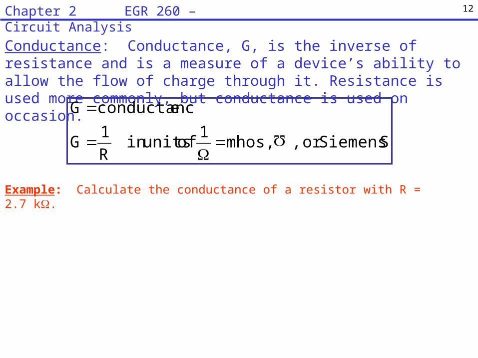
Conductance: Conductance, G, is the inverse of resistance and is a measure of a device’s ability to allow the flow of charge through it. Resistance is used more commonly, but conductance is used on occasion.
Example: Calculate the conductance of a resistor with R = 2.7 k.
S Siemens,or , mhos, 1
of unitsin R
1 G
econductanc G
12Chapter 2 EGR 260 – Circuit Analysis
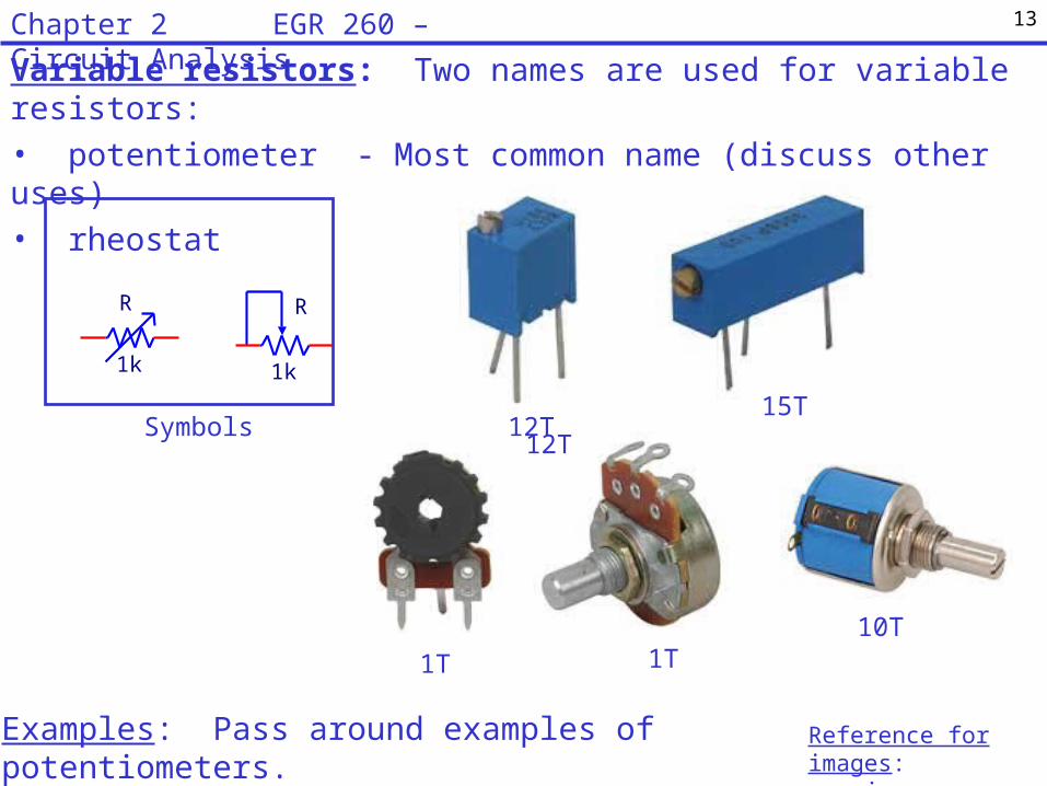
Variable resistors: Two names are used for variable resistors:
• potentiometer - Most common name (discuss other uses)
• rheostat
Examples: Pass around examples of potentiometers.
¾ turn (1T) and 15T turn potentiometers.
R
1k
R
1k
Symbols 12T15T
1T 1T10T
Reference for images: www.jameco.com
12T
13Chapter 2 EGR 260 – Circuit Analysis
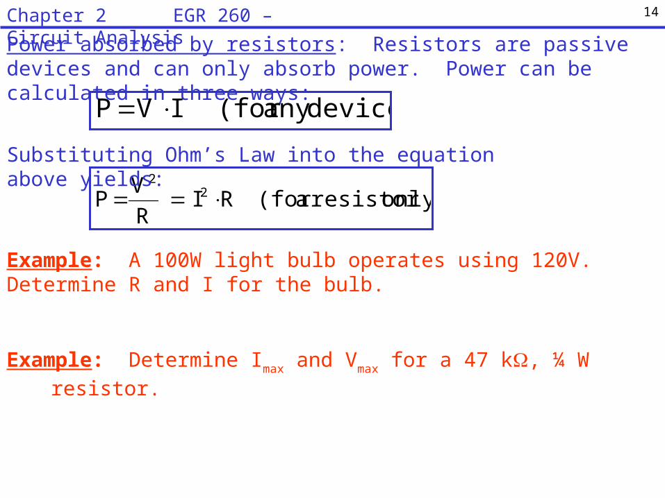
Power absorbed by resistors: Resistors are passive devices and can only absorb power. Power can be calculated in three ways:
Example: A 100W light bulb operates using 120V. Determine R and I for the bulb.
device)any (for IV P
only)resistor a(for RI R
V P 2
2
Substituting Ohm’s Law into the equation above yields:
Example: Determine Imax and Vmax for a 47 k, ¼ W resistor.
14Chapter 2 EGR 260 – Circuit Analysis
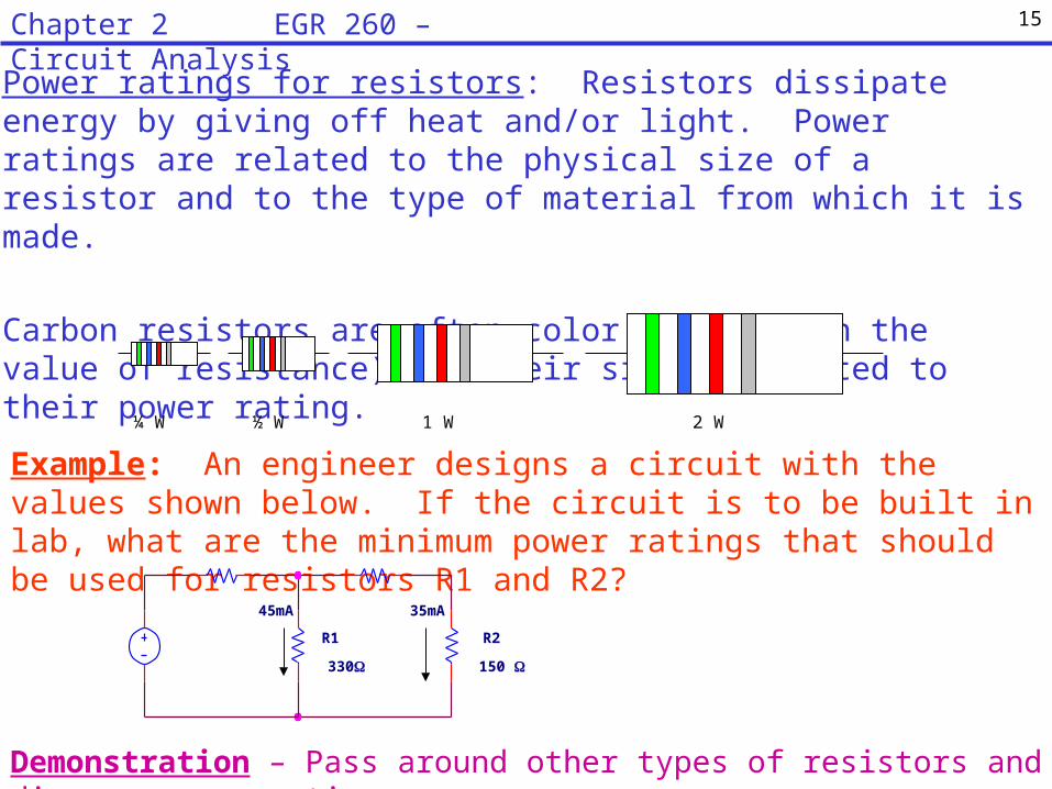
Power ratings for resistors: Resistors dissipate energy by giving off heat and/or light. Power ratings are related to the physical size of a resistor and to the type of material from which it is made.
Carbon resistors are often color coded (with the value of resistance) and their size is related to their power rating.
¼ W ½ W 1 W 2 W
Example: An engineer designs a circuit with the values shown below. If the circuit is to be built in lab, what are the minimum power ratings that should be used for resistors R1 and R2?
R2
150
R1
330
45mA 35mA
Demonstration – Pass around other types of resistors and discuss power ratings.
15Chapter 2 EGR 260 – Circuit Analysis
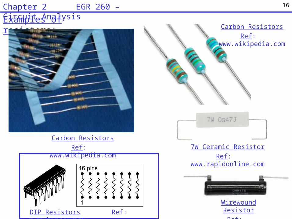
Examples of resistors:
Wirewound Resistor
Ref: www.newark.com
Carbon Resistors
Ref: www.wikipedia.com
Carbon Resistors
Ref: www.wikipedia.com
DIP Resistors Ref: www.jameco.com
7W Ceramic Resistor
Ref: www.rapidonline.com
16Chapter 2 EGR 260 – Circuit Analysis
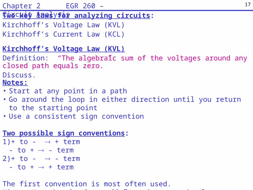
Two key laws for analyzing circuits:Kirchhoff’s Voltage Law (KVL)Kirchhoff’s Current Law (KCL)
Kirchhoff’s Voltage Law (KVL)Definition: “The algebraic sum of the voltages around any closed path equals zero.”Discuss.
Notes:• Start at any point in a path• Go around the loop in either direction until you return to the starting point• Use a consistent sign convention
Two possible sign conventions:1)+ to - + term
- to + - term2)+ to - - term
- to + + term
The first convention is most often used. Hint: Use the sign that you hit first going around a loop.
17Chapter 2 EGR 260 – Circuit Analysis
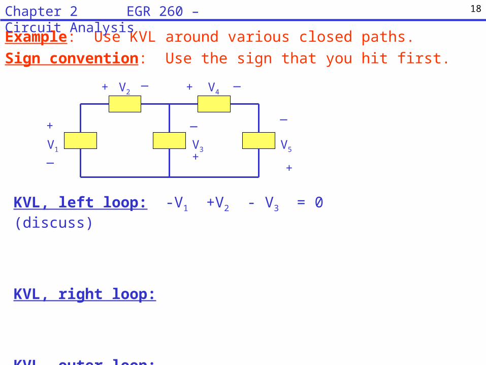
Example: Use KVL around various closed paths.
Sign convention: Use the sign that you hit first.
V1
V2
V3
V4
V5
+
+
+
_
+_
_ _
+
_
KVL, left loop: -V1 +V2 - V3 = 0 (discuss)
KVL, right loop:
KVL, outer loop:
18Chapter 2 EGR 260 – Circuit Analysis

Example: Use KVL around the circuit below to find the voltage Vx. Discuss
the difference in a sign due to convention and a sign due to the value of the
voltage.7V
12V
13V
-9V 17V
-19V
Vx
_+
a
b
Two-subscript notation: Generally the polarity must be indicated with a voltage for it to be clearly defined. Another way to specify the polarity is to add subscripts indicating the location of the positive and negative terminals. For example:
VAB = the voltage from A to B with the positive terminal at A
VBA = the voltage from A to B with the positive terminal at B ( Note that VAB = -VBA)
VAB
A
B
+
_VBA
A
B
_
+
19Chapter 2 EGR 260 – Circuit Analysis
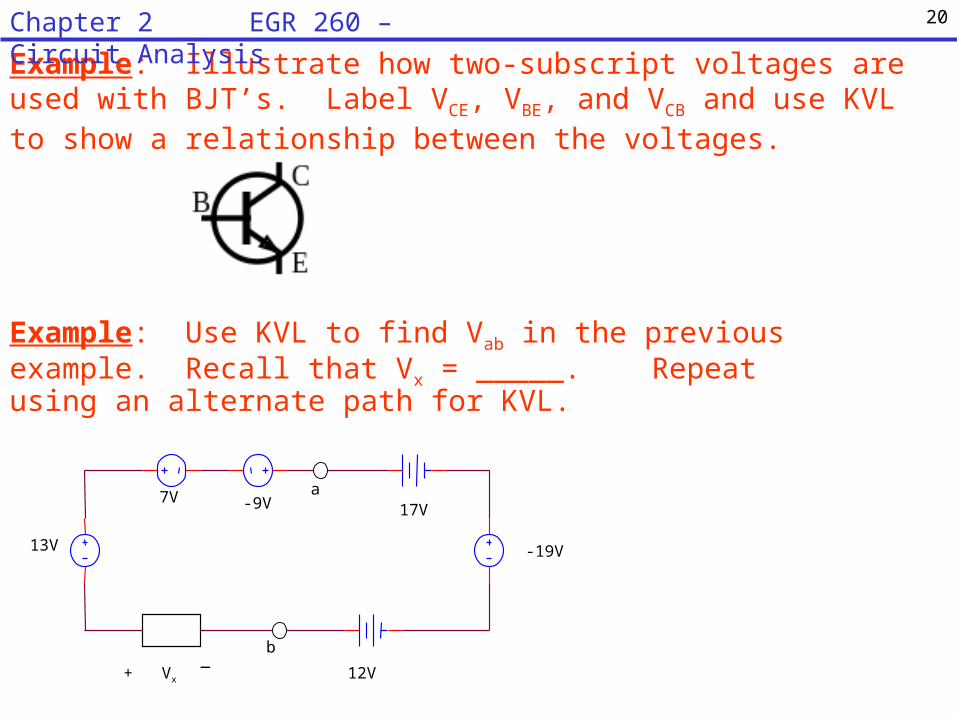
Example: Use KVL to find Vab in the previous example. Recall that Vx = _____. Repeat using an alternate path for KVL.
7V
12V
13V
-9V 17V
-19V
Vx
_+
a
b
Example: Illustrate how two-subscript voltages are used with BJT’s. Label VCE, VBE, and VCB and use KVL to show a relationship between the voltages.
20Chapter 2 EGR 260 – Circuit Analysis

Node: A node is a junction in a circuit where two or more elements have a common connection. Additionally, there can never be two nodes connected by a wire (this would form a single node).
Kirchhoff’s Voltage Law can be used to show an important law about parallel elements. Definitions for nodes and parallel elements are first introduced.
Note: Nodes are sometimes confused with connection points (or solder points). For example, the text typically uses solid circles (dots) to indicate connection points where three or more elements connect. These points may or may not be nodes.
21Chapter 2 EGR 260 – Circuit Analysis
Node, but not a connection
point
Node and a connection point
These two connection point are a single node
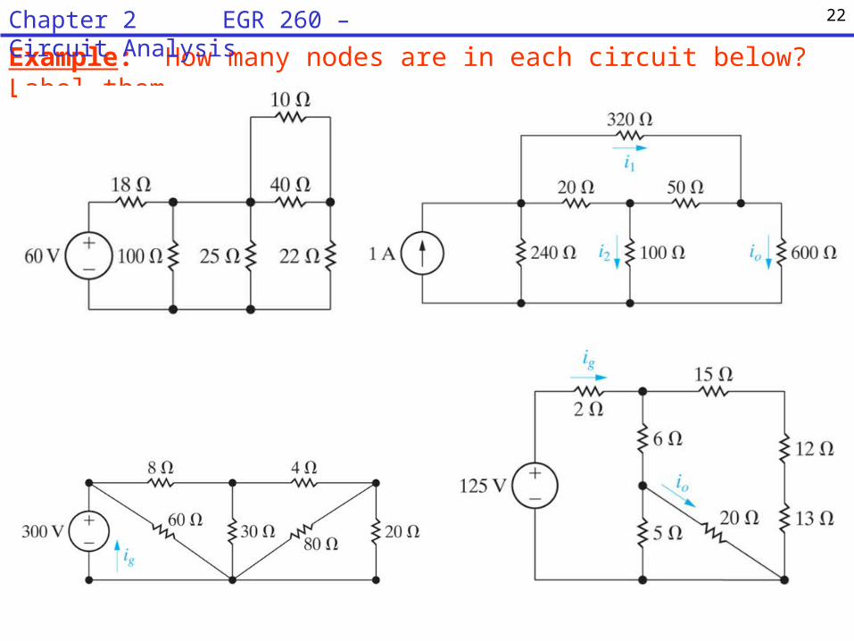
Example: How many nodes are in each circuit below? Label them.
22Chapter 2 EGR 260 – Circuit Analysis

Parallel Circuit Elements: Two circuit elements are “in parallel” if they share the same two nodes.
Example: Identify the nodes and the parallel elements in the circuit below.
R7
R6
R3 R8
R1
R2
R4
R5
Example: Identify the nodes and the parallel elements in the circuit below.
R4
R6
R1
R2
R5R3
Note: Parallel circuit elements do not always appear as parallel lines!
23Chapter 2 EGR 260 – Circuit Analysis

Use KVL to show that:
Parallel circuit: Circuits consisting of only parallel circuit elements are referred to as parallel circuits. Note that the order of the elements is not important.
Parallel circuit elements have the same voltage.
Example: Draw an example of a parallel circuit.
Example: Household circuits (on a single circuit breaker) are examples of parallel circuits. Draw an example of a household circuit.
24Chapter 2 EGR 260 – Circuit Analysis

Kirchhoff’s Current Law (KCL)Three possible definitions are listed below. The first is the most general.
Definition: “The algebraic sum of the currents crossing any closed surface equals zero.”
Discuss.
Definition: “The algebraic sum of the currents entering and leaving a node equals zero.”
Discuss.
Definition: “The sum of the currents entering a node equals the sum of the currents leaving a node.”
Discuss.
Note: Think of a closed surface as a bubble. If the bubble collapses to a point, it could be a node. So applying KCL to a node is a special case and applying it to a closed surface is more general.
25Chapter 2 EGR 260 – Circuit Analysis

Example: Use KCL at various closed surfaces and nodes. Discuss using a sign convention.
I1
I2
I3
I4
I5
I6
AB
C
D
Two possible sign conventions:1)Out = +, In = -2)Out = -, In = +
The first convention is most often used.
KCL, node A (out = +): +I1 – I2 + I6 = 0
KCL, node B (out = +):
KCL, closed surface #1 (out = +):
Closed Surface #1
26Chapter 2 EGR 260 – Circuit Analysis
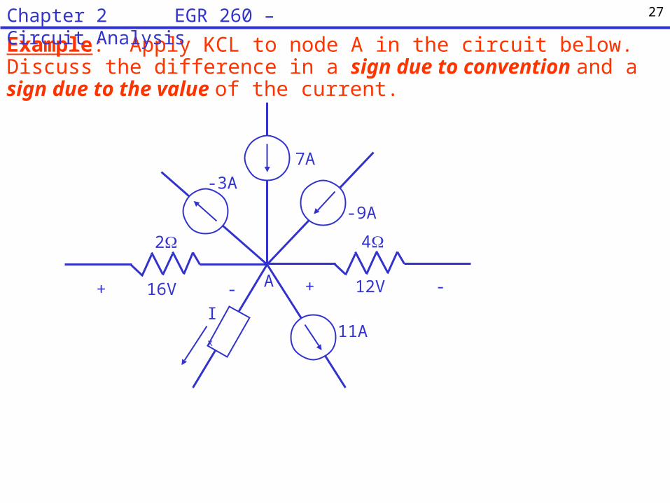
Example: Apply KCL to node A in the circuit below. Discuss the difference in a sign due to convention and a sign due to the value of the current.
7A
-3A
-9A
+ 12V -+ 16V -
42
Ix
A
11A
27Chapter 2 EGR 260 – Circuit Analysis

Example: Find the current I1 in the circuit shown below. Hint: draw a bubble that encompasses the right half of the circuit and apply KCL.
There are times when the most general definition of KCL is the most powerful. Two examples are provided below.
10A
I1
+-
Example: An IEEE standard states that all currents should be defined as entering a device. Label the currents IB, IC, and IE for the Bipolar Junction Transistor (BJT) and use KCL to find the relationship between the currents.
28Chapter 2 EGR 260 – Circuit Analysis

Series Elements - 2 elements are considered to be “in series” if they share one node and no other element is connected to that node.
Use KCL to show that: Series circuit elements have the same current.
Example: Draw an example of a series circuit.
29Chapter 2 EGR 260 – Circuit Analysis

Combining voltage sources
Key point: Voltage sources add algebraically in series.
Example:
Example: Illustrate the well-known fact that flashlight batteries must be put in the flashlight with the correct polarity.
30Chapter 2 EGR 260 – Circuit Analysis
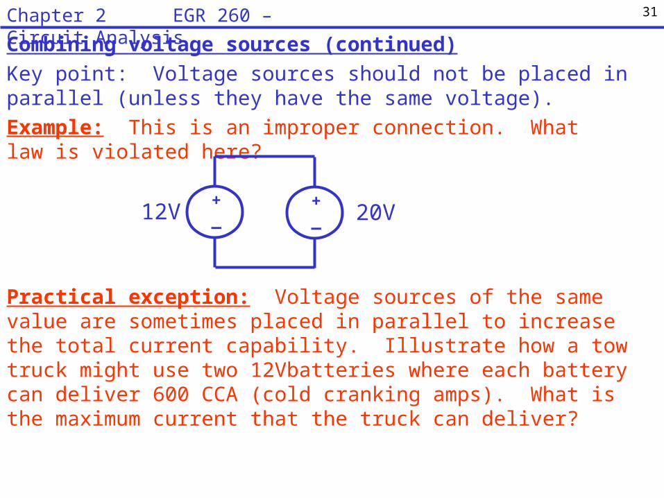
Combining voltage sources (continued)
Key point: Voltage sources should not be placed in parallel (unless they have the same voltage).
Example: This is an improper connection. What law is violated here?
Practical exception: Voltage sources of the same value are sometimes placed in parallel to increase the total current capability. Illustrate how a tow truck might use two 12Vbatteries where each battery can deliver 600 CCA (cold cranking amps). What is the maximum current that the truck can deliver?
31Chapter 2 EGR 260 – Circuit Analysis
+_12V
+_ 20V

Combining current sources
Key point: Current sources add algebraically in parallel.
Example:
Example:
32Chapter 2 EGR 260 – Circuit Analysis

Combining current sources (continued)
Key point: Current sources should not be placed in series (unless they have the same current).
Example: This is an improper connection. What law is violated here?
Practical exception: Current sources of the same value could be placed in series to increase the total voltage capability. For example, suppose that two 10A current sources each have Vmax = 100V and they are placed in series. Illustrate.
33Chapter 2 EGR 260 – Circuit Analysis
2A 6A

Valid versus invalid circuits
The text makes a point that all circuits must always satisfy KVL and KCL. A circuit that does not satisfy KVL or KCL is invalid and would be impossible to construct (or the circuit or equipment might be damaged). A few initial problems in the text ask is a circuit is valid. To test this, simply check KVL around various paths and KCL at various nodes to insure that no invalid equations occur.
Example: Is the following circuit valid?
100V
5A200V
8A
6A
Example: Is the following circuit valid?
150V
200V
100V
75V4A
34Chapter 2 EGR 260 – Circuit Analysis
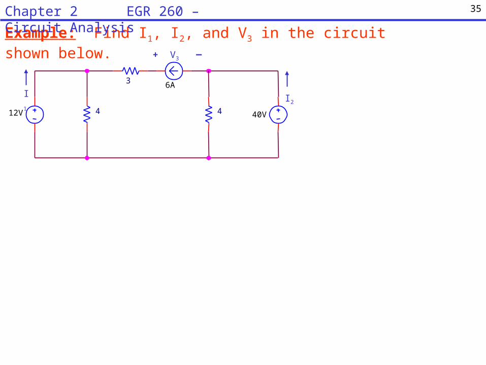
Example: Find I1, I2, and V3 in the circuit shown below.
40V
3
412V
6A
4
I1 I2
V3+ _
35Chapter 2 EGR 260 – Circuit Analysis
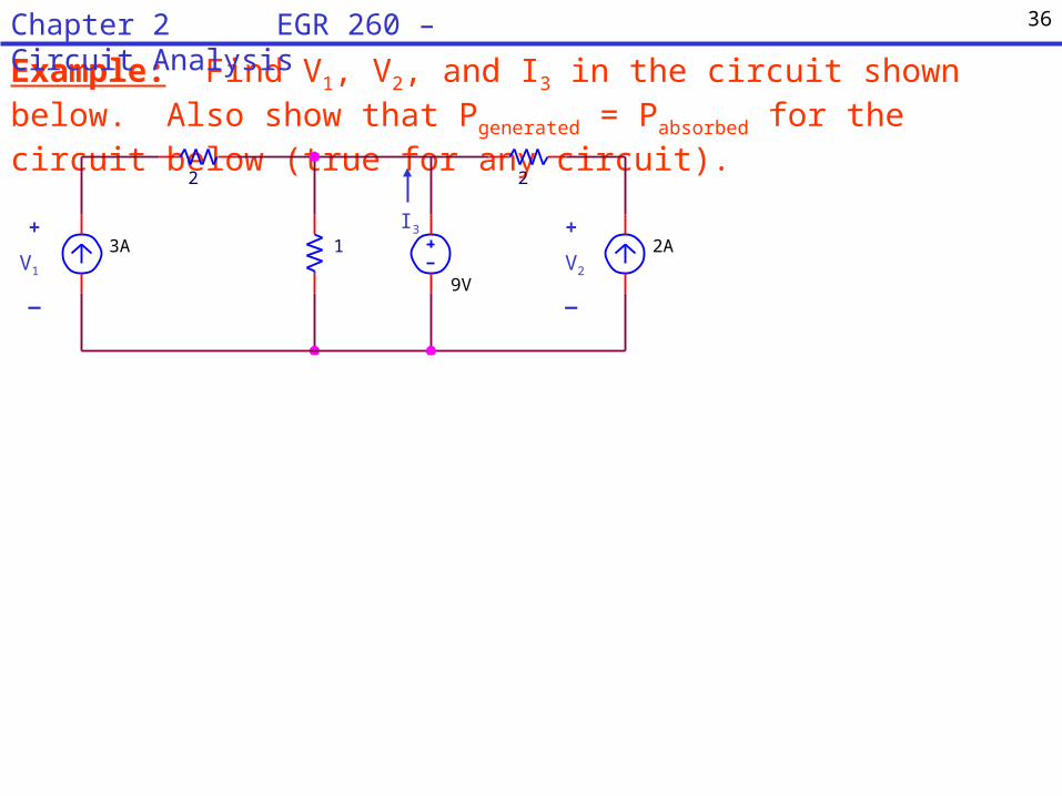
Example: Find V1, V2, and I3 in the circuit shown below. Also show that Pgenerated = Pabsorbed for the circuit below (true for any circuit).
I3
V2
+
_
3A
2
9V
2
1 2AV1
+
_
36Chapter 2 EGR 260 – Circuit Analysis

Example: Find ig, ia, vg, and the total power developed in the circuit shown below.
37Chapter 2 EGR 260 – Circuit Analysis

Example: If ia = 4A and ib = 2A, find ig, vg, and the power dissipated by each
resistor.
38Chapter 2 EGR 260 – Circuit Analysis
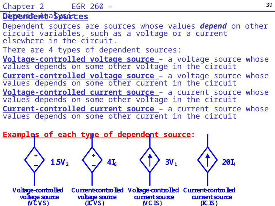
Dependent SourcesDependent sources are sources whose values depend on other circuit variables, such as a voltage or a current elsewhere in the circuit.There are 4 types of dependent sources:Voltage-controlled voltage source – a voltage source whose values depends on some other voltage in the circuitCurrent-controlled voltage source – a voltage source whose values depends on some other current in the circuitVoltage-controlled current source – a current source whose values depends on some other voltage in the circuitCurrent-controlled current source – a current source whose values depends on some other current in the circuit
Examples of each type of dependent source:
+ _ 3V1 20I4 1.5V2
+ _ 4I6
Voltage-controlled voltage source
(VCVS)
Current-controlled voltage source
(ICVS)
Voltage-controlled current source
(VCIS)
Current-controlled current source
(ICIS)
39Chapter 2 EGR 260 – Circuit Analysis
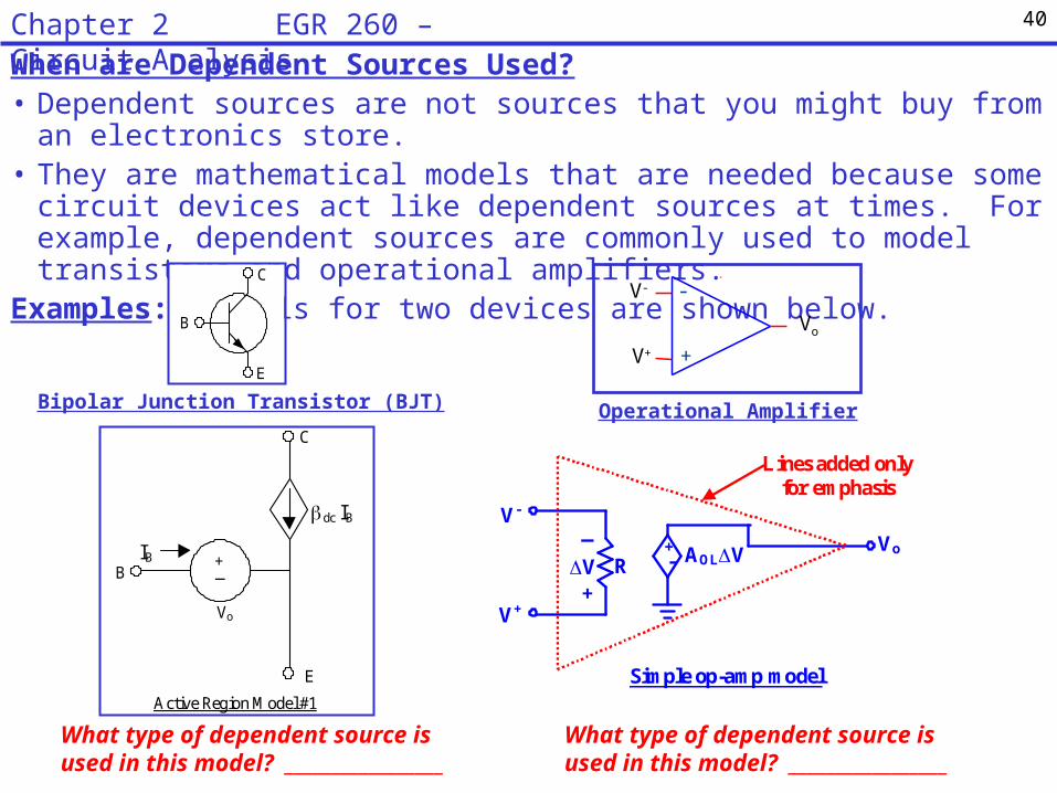
When are Dependent Sources Used?• Dependent sources are not sources that you might buy from an electronics store.• They are mathematical models that are needed because some circuit devices act like
dependent sources at times. For example, dependent sources are commonly used to model transistors and operational amplifiers.
Examples: Models for two devices are shown below.
Bipolar Junction Transistor (BJT) Operational Amplifier
40Chapter 2 EGR 260 – Circuit Analysis
Vo
_ +
C
B
E
Active Region Model #1
dc IB
IB
C
E
B
R Vo +
- AOLV V +
_ V-
V+
Simple op-amp model
Lines added only for emphasis
V-
V+
Vo
-
+
What type of dependent source is used in this model? _________________
What type of dependent source is used in this model? _________________
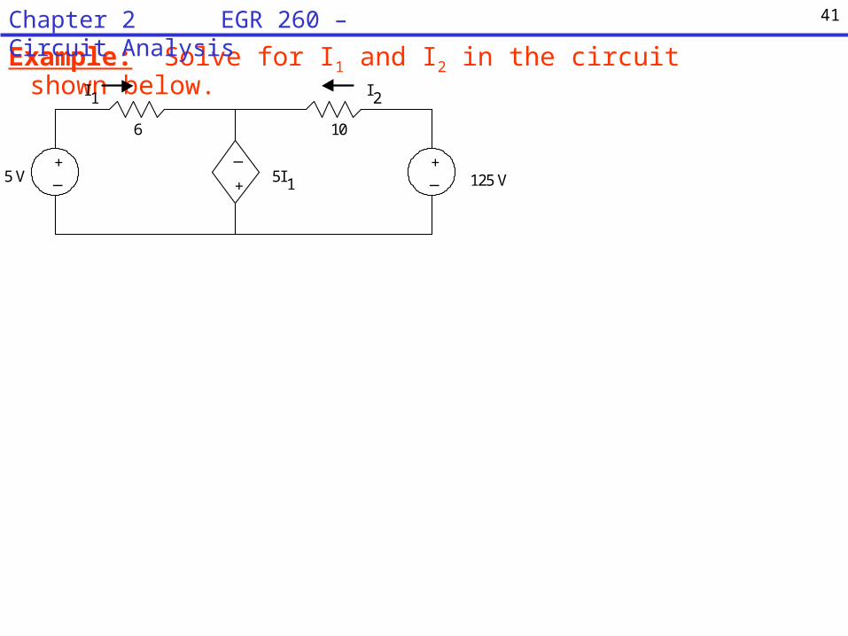
Example: Solve for I1 and I2 in the circuit shown below.
+ _
6 10
I 1
+
_ 5I 1
I 2
5 V + _ 125 V
41Chapter 2 EGR 260 – Circuit Analysis

Example: Solve for I1 and V1 in the circuit shown below.
+ _
8 4
I 1
+ _
10I 1
V 1
12 V + _ 8 V
+ _
3V 1
+ _
42Chapter 2 EGR 260 – Circuit Analysis

Example: Show that Pgenerated = Pabsorbed for the circuit below.
1k
V 1
9 mA + _ 5 V 0.002V
1
+ _
43Chapter 2 EGR 260 – Circuit Analysis