READ THIS FIRST: PAN Manager Configuration...
73
READ THIS FIRST: PAN Manager Configuration Guide For BladeFrame ® BF400 S2 and BladeFrame ® BF200 Document Number 430-SB0072 August 2010 PM5.2_BF
Transcript of READ THIS FIRST: PAN Manager Configuration...

READ THIS FIRST: PAN Manager Configuration Guide
For BladeFrame® BF400 S2 and BladeFrame® BF200
Document Number 430-SB0072
August 2010
PM5.2_BF

CopyrightCopyright © 2010 Egenera, Inc. All rights reserved.
This document, and the product described in it, is furnished under license and may only be used in accordance with the terms of such license. The content of this document is furnished for information purposes only and is subject to change without notice.
Egenera, Egenera stylized logos, BladeFrame, BladeLatch, BladeMate, BladePlane, cBlade, Control Blade, PAN Manager, pBlade, Processing Blade, sBlade, and Switch Blade are either registered trademarks or trademarks of Egenera, Inc. in the United States and/or other countries.
PRIMERGY is a registered trademark of Fujitsu Technology Solutions.
AMD, AMD Opteron, and AMD Athlon are trademarks of Advanced Micro Devices, Inc..
EMC, CLARiiON, and Symmetrix are registered trademarks of EMC Corporation.
The IBM Developer Kit for Linux, Java 2 Technology Edition contains software which is copyright IBM Corporation, Sun Microsystems Inc., Hewlett-Packard Co., and X Consortium.
Intel and Itanium are registered trademarks and Xeon is a trademark of the Intel Corporation in the United States and other countries.
Sun, Sun Microsystems, the Sun Logo, Solaris, and the Java logo are trademarks or registered trademarks of Sun Microsystems, Inc. in the United States and other countries.
Linux is a registered trademark of Linus Torvalds.
Microsoft and Windows are either registered trademarks or trademarks of Microsoft Corporation in the United States and/or other countries. The virtual VGA console uses Microsoft Terminal Services Advanced Client (TSAC), which is a copyright of Microsoft Corporation.
MindTerm is copyright AppGate AB.
Nero is a trademark of Nero AG.
NetApp is a registered trademark and Network Appliance is a trademark of Network Appliance, Inc.
Oracle9i is a trademark of Oracle Corporation.
Red Hat is a registered trademark of Red Hat, Inc. in the United States and other countries.
SUSE is a registered trademark of SUSE LINUX Products GmbH, a Novell business.
VMware, Virtual SMP, and VMotion are registered trademarks or trademarks of VMware, Inc.
Xen, XenSource, XenServer, and XenEnterprise are either registered trademarks or trademarks of Citrix Systems, Inc. in the United States and/or other countries.
All other company and product names are trademarks or registered trademarks of their respective holders.
Printed in the United States of America.[100715:112621]
Egenera, Inc., 165 Forest Street, Marlboro, Massachusetts 01752.

iii
Contents
Preface
Customer Support .................................................................................................... viii
Document Conventions ........................................................................................... viii
Chapter 1: BladeFrame Configuration
Fujitsu Technology Solutions Terminology ............................................................ 1-3
Prerequisites Before Using This Document ............................................................ 1-4
Required Materials .................................................................................................. 1-4
Chapter 2: Making BladeFrame Network Connections
Layout of BladeFrame Network Switches .............................................................. 2-1Making BladeFrame BF400 S2 Network Connections .................................... 2-2Making BladeFrame BF200 Network Connections ......................................... 2-5
BladeFrame Network Connection Requirements .................................................... 2-7Cable Types and Requirements ........................................................................ 2-8Port Numbering Requirements ......................................................................... 2-8Feed Network Cables to Ports .......................................................................... 2-8
Connecting Network Cables to the cBlades ............................................................ 2-9Connections to a BladeFrame BF400 S2.......................................................... 2-9Connections to a BladeFrame BF200............................................................. 2-12

READ THIS FIRST: PAN Manager Configuration Guide
iv
Chapter 3: Making BladeFrame SAN Connections
Layout of SAN Switches ......................................................................................... 3-1Before Connecting SAN Cables to a BladeFrame BF400 S2 .......................... 3-2Before Connecting SAN Cables to a BladeFrame BF200................................ 3-3
SAN Connection Requirements .............................................................................. 3-4Connection Orientation Requirements ............................................................. 3-4Cable Requirements.......................................................................................... 3-4Record the SCSI Port Numbers........................................................................ 3-4
Connecting SAN Cables to the Platform ................................................................. 3-5
Mapping Physical SAN Ports to a WWN on Each HBA ........................................ 3-7
Chapter 4: Configuring BladeFrame Power Settings and Other TasksConfiguring Power for BladeFrame BF400 S2s That Have
PIM-Rs...................................................................................................... 4-2Specify the Preferred Power Cord.................................................................... 4-3
Chapter 5: Configuring a Platform After You Complete Physical Connections
Opening Serial Consoles on the cBlades ................................................................. 5-2Open a Serial Console on a cBlade .................................................................. 5-2Visually Inspect Cable Connections................................................................. 5-3Supply Power.................................................................................................... 5-4Open a Console on a cBlade Remotely ............................................................ 5-4
Configuring Unique IP Addresses for PAN Manager and the cBlades and cBlade Hostnames ....................................................................................................... 5-5
Testing Network Connectivity ................................................................................ 5-7
Using the PAN Manager GUI ................................................................................. 5-8Opening the GUI .............................................................................................. 5-8

Contents
v
Modifying a PAN Manager Internal Network ........................................................ 5-9
Synchronizing the Date and Time with an External Time Source (Recommended, but Optional) ........................................................................................................ 5-10
(Optional) Resetting the PAN Identification ......................................................... 5-11Configuring PAN Attributes........................................................................... 5-12
Testing Physical Connectivity Between the cBlades and the SAN ....................... 5-14Examine the cBlade Indicator Lights ............................................................. 5-14Display all SAN Devices................................................................................ 5-15
Appendixes
Appendix A: Adding or Replacing Processing Blades
Adding a pBlade ..................................................................................................... A-2
Replacing a pBlade ................................................................................................. A-3Selecting the pBlade for Removal ................................................................... A-3Removing an Inactive pBlade ......................................................................... A-4Shutting Down an Active pServer ................................................................... A-4
Reinserting a Removed pBlade .............................................................................. A-5
Failing a pServer Back to its Original pBlade ........................................................ A-6
Appendix B: BladeFrame Environmental Requirements
Appendix C: BladeFrame Power Status Indicators
Understanding Blade Indicator Lights ................................................................... C-1
Understanding PIM-R Indicator Lights .................................................................. C-2

READ THIS FIRST: PAN Manager Configuration Guide
vi

PM5.2_BF vii
Preface
Welcome to PAN Manager PM5.2_BF. READ THIS FIRST: PAN Manager Configuration Guide is part of the PAN Manager documentation set. Its purpose is to describe the tasks that need to be performed before installing PAN Manager software on your BladeFrame.
Audience — READ THIS FIRST: PAN Manager Configuration Guide is for PAN Administrators.
Topics — Read this book to learn about the following:
• Chapter 2, “Making BladeFrame Network Connections”
• Chapter 3, “Making BladeFrame SAN Connections”
• Chapter 4, “Configuring BladeFrame Power Settings and Other Tasks”
• Chapter 5, “Configuring a Platform After You Complete Physical Connections”
PAN Manager Documentation Set — To learn about the other documents available in the PAN Manager documentation set, see the PAN Manager Release Notes.
PAN Manager Features — To learn about the PAN Manager features available in the current release, see the PAN Manager Release Notes.

READ THIS FIRST: PAN Manager Configuration Guide
viii PM5.2_BF
Customer Support
For customer support regarding this product and its documentation, please use the following contact information:
Fujitsu Technology Solutions customer support
Document Conventions
Internet http://support.ts.fujitsu.com
Telephone See the Help Desk information at http://manuals.ts.fujitsu.com/primergyservers.html, under Contact.
Convention Description
> Directory-level delimiter used to navigate the left pane of the PAN Manager GUI.
Example: Resources > Networking
Sans serif italics Variable text, such as a path, a filename, or an LPAN name.
Example: lpan -c lpanname
Sans serif Text that must be typed as shown.
Example: Type root at the login prompt.
Bold The name of a field or window element appearing in a GUI. It also highlights default values in PAN Manager man pages.
Example: In the Users page...

Preface
PM5.2_BF ix
Italics Text that is emphasized.
Example: Do not connect the power.
[text] Text that is optional to a command.
{text} A set of choices, one of which is required.
| Separation of mutually exclusive choices in syntax lines.
Example: lpan [-aD | -rD]{switch | SCSI_ID} lpanname
Note Information of importance or that may not fit in main text.
Caution Failure to heed a caution could result in loss of data.
Warning — Failure to heed a warning could result in physical harm to the user or the hardware.
Convention Description
!

READ THIS FIRST: PAN Manager Configuration Guide
x PM5.2_BF

PM5.2_BF 1-1
Chapter 1BladeFrame
Configuration
Welcome to the Fujitsu Technology Solutions PAN environment.
This document describes essential configuration tasks that you must perform immediately after your authorized support vendor installs your new BladeFrame BF400 S2 or BladeFrame BF200. It is essential to perform the tasks described in this document before you integrate the platform into your SAN, or configure servers or applications.
Perform the tasks in this document only if you are configuring a new BladeFrame BF400 S2 or BladeFrame BF200.
We recommend performing the tasks in this document in the following order:
• Review Fujitsu Technology Solutions Terminology (ahead in this chapter)
• Prerequisites Before Using This Document (ahead in this chapter)
• Making BladeFrame Network Connections (Chapter 2)
• Making BladeFrame SAN Connections (Chapter 3)

READ THIS FIRST: PAN Manager Configuration Guide
1-2 PM5.2_BF
• Configuring BladeFrame Power Settings and Other Tasks (Chapter 4)
• to finalize your PAN Manager configuration, install Fujitsu Technology Solutions license files, and perform other important tasks.
You should also take a few moments to review the BladeFrame Environmental Requirements described in Appendix A, and the BladeFrame Power Status Indicators in Appendix B.
To perform many of these essential tasks, you use the PAN Manager software that your technical service engineer has installed on the cBlades. (The technical service engineer installed an operating system and PAN Manager on each cBlade.)
PAN Manager provides a single control point for allocating, configuring, and monitoring both physical and logical resources on a platform or on a group of platforms that are configured as a single Processing Area Network (PAN).
After PAN Manager is running on the platform and you make I/O connections, use the chapter “Configuring a Platform After You Complete Physical Connections” on page 5-1 to finalize configurations, install Fujitsu Technology Solutions license files, and perform other PAN Manager tasks.

BladeFrame Configuration
PM5.2_BF 1-3
Fujitsu Technology Solutions Terminology
This document relies on the following Fujitsu Technology Solutions-specific terms:
Term Description
Chassis The rack frame that contains the BladeFrame hardware.
Control Blades (cBlades) Blades that handle system and internal network management and provide pBlades with access to external storage, external networks, and DVD-ROM drives.
External Management Network
The network through which administrators communicate with PAN Manager. For security purposes, you should configure this connection on a secure or private network.
Platform The fundamental unit for organizing processing resources in a PAN. A platform consists of a set of pBlades, a redundant pair of cBlades, a set of switches, and a high-speed internal fabric or network connecting all the blades to the switches.
PAN Manager The software that manages a platform and its hardware and software resources. PAN Manager provides both a GUI and CLI for administrators.
Premises Network The data network that is external to PAN Manager control. This is sometimes referred to as pServer Network. Premises network traffic flows into and out of PAN Manager control through rEth Interfaces.
Processing Area Network (PAN)
A distributed set of physical and virtual resources, including processors, disks, tapes, and network connections.
Processing Blades (pBlades) Blades that provide independent processing and memory capabilities.
Redundant Ethernet interface: rEth Interface (rEth)
physical Ethernet interfaces that are configured on each cBlade with the ability to dynamically balance incoming and outgoing network traffic. If one member of the rEth pair fails, the other rEth pair member assumes all incoming and outgoing network traffic.

READ THIS FIRST: PAN Manager Configuration Guide
1-4 PM5.2_BF
Prerequisites Before Using This Document
At this point, your technical service engineer has done the following:
• Provided you with the WWN paper that was shipped with your platform or a replacement cBlade. This paper allows provides the WWNs for the HBAs on your platform.
• Installed the platform hardware
• Installed the firmware for the cBlades and pBlades
• Run the installation verification program (IVP)
• Installed the cBlade software and associated patches
If these tasks have not been completed, do not continue with the tasks in this document. Instead, contact Fujitsu Technology Solutions customer support or your authorized support vendor.
If these tasks have been completed, go to Chapter 2, “Making BladeFrame Network Connections”.
Required Materials
You need the following materials to complete this installation:
• Laptop computer with terminal console software.
• Extension cord or power strip. (Optional if you want to use your laptop’s power supply, and there is no nearby power outlet.)
• Null modem serial cable with DB-9 female connectors on both ends. The cable must be long enough to reach between the back of the platform and your laptop.

PM5.2_BF 2-1
Chapter 2Making BladeFrame
Network Connections
This chapter describes how to connect your BladeFrame to your site’s local network, and perform other network configuration tasks:
• Layout of BladeFrame Network Switches
• BladeFrame Network Connection Requirements
• Connecting Network Cables to the cBlades
Layout of BladeFrame Network Switches
During the BladeFrame chassis installation, the installer must feed all network cables to the chassis so the cables easily plug into the networking ports. Follow the procedure that is appropriate to your platform.
• Making BladeFrame BF400 S2 Network Connections
• Making BladeFrame BF200 Network Connections

READ THIS FIRST: PAN Manager Configuration Guide
2-2 PM5.2_BF
Making BladeFrame BF400 S2 Network Connections
Physical Location of Ports on BladeFrame BF400 S2 cBlades
Before plugging the network cables into the cBlades, note the location and numbering of the network ports (Figure 2.1). The I/O panel on a cBlade EX is located behind the front bezel.
To access the network ports on each cBlade, remove the bezel located on the lower half of the cBlade. To do this, insert a long, slim #1 screwdriver through the slots, loosen the two captive #1 Phillips head screws, and pull the cover forward to expose the BladeFrame BF400 S2 cBlade ports (Figure 2.1).
Figure 2.1 cBlade EX Bezel Removed Showing Fibre Channel and Ethernet Ports
Serial Port Connections
One serial port is located on the front of each BladeFrame BF400 S2 cBlade (Figure 2.1). Installers use a serial console connection from both cBlades to a laptop computer to initially boot the platform and configure PAN Manager. See “Configuring Unique IP Addresses for PAN Manager and the cBlades and cBlade Hostnames” on page 5-5 for information about uniquely
SlotsPCI Expansion
Serial Port

Making BladeFrame Network Connections
PM5.2_BF 2-3
configuring the platform on your local network as well as make hostname changes to the cBlades that are appropriate for the installation site.
External Management Interface Connections
For External Management Network connections, you use the port labelled Management 10/100/1000 on the lower right face of the cBlade (Figure 2.1).
Premises Network Connections
For Premises Network connections to each BladeFrame BF400 S2 platform, you use either Gigabit Ethernet switch ports located on the lower face of each cBlade or 1000BaseSX Ethernet switch ports located on a PCI-X network interface card above the BladeLatch on each cBlade (Figure 2.1).
The hard-coded port numbers for each network port are identified in (Figure 2.1) and (Figure 2.2).

READ THIS FIRST: PAN Manager Configuration Guide
2-4 PM5.2_BF
Figure 2.2 PCI-X Ethernet Ports and Hard-Coded Port Numbering
Note: The BladeFrame BF400 S2 supports four Gigabit Ethernet connections and four 1000BaseSX Ethernet ports per cBlade. The Gigabit Ethernet connections require an SFP (Small Form Factor Pluggable) connector port interface. The SFP connectors are factory installed and are not hot-swappable. If you have problems with the SFP connectors, contact Fujitsu Technology Solutions customer support or your authorized service vendor.
LED Indicators for GigaBit Network Connections
To the right of each GigaBit Ethernet port (excluding those on the PCI-X card) are two LED indicators. The GigaBit Ethernet LED indicators are labeled L (Link) and A (Activity); see Table 2.1.
eth15
eth16
eth17
eth18
PCI-Xnetwork
ports

Making BladeFrame Network Connections
PM5.2_BF 2-5
Table 2.1 Ethernet Port LED Behavior (cBlade EX and cBlade ES)
Making BladeFrame BF200 Network Connections
Physical Location of Ports on BladeFrame BF200 cBlades
Before plugging the network cables into the cBlade ES chassis, note the location and numbering of the network ports. All I/O ports on a cBlade ES are located in the rear of the chassis on the BladeFrame BF200 connection panel. This connection panel differs between the 20-AMP (Figure 2.3) or 30-AMP platform (Figure 2.4) models.
The BladeFrame BF200 connection panel is designed so that physical connections to cBlade 1 (C1) are distinguished from physical connections to cBlade 2 (C2). The panel is laid out so that each IO connection is located closer to the cBlade to which the panel connects it. Therefore, the serial, Gigabit Ethernet, management, and SAN port connections on the C1 side each connect directly to the BladeFrame BF200 cBlade 1; the port connections on the C2 side connect directly to the BladeFrame BF200 cBlade 2.
LED behavior:
LED (green) LED (amber)Status:
(Off) (Off) Power is ON, but no network cable is connected
Steady on (Off) Network link is established
Steady on Flashing Online, with network activity

READ THIS FIRST: PAN Manager Configuration Guide
2-6 PM5.2_BF
Figure 2.3 cBlade ES Ports (20-Amp Chassis)
Figure 2.4 cBlade ES Ports (30-Amp Chassis)
Serial Port Connections
Two serial ports (labelled Serial Port) are located on the BladeFrame BF200 connection panel (Figure 2.3 and Figure 2.4). Each connects directly to the C1 or C2 cBlade. Installers use serial console connections from the BladeFrame BF200 connection panel to a laptop computer to initially boot the platform and configure PAN Manager. See “Opening Serial Consoles on the cBlades” on page 5-2 for information on connecting your laptop to the serial ports on each connection panel. See “Configuring Unique IP Addresses for PAN Manager and the cBlades and cBlade Hostnames” on page 5-5 for information about uniquely configuring the platform on your local network as well as make hostname changes to the cBlades that are appropriate for the installation site.
Serial Ports
Serial Ports

Making BladeFrame Network Connections
PM5.2_BF 2-7
External Management Interface Connections
For External Management Network connections, you use the port labelled Management 10/100 Eth0 located between the two Fibre Channel ports and the two GigaBit ETHERNET ports (Figure 2.3 and Figure 2.4).
Premises Network Connections
For Premises Network connections to each BladeFrame BF200 connection panel, you use the two ports labelled GigaBit ETHERNET located on each (C1 or C2) side of the panel.
The hard-coded port numbers for each network port are identified in (Figure 2.3) and (Figure 2.4).
Note: The BladeFrame BF200 supports two Gigabit Ethernet connections per cBlade. Each connection plugs into an SFP (Small Form Factor Pluggable) connector before it is plugged into the port. The SFP connectors are factory installed and are not hot-swappable. If you have problems with the SFP connectors, contact Fujitsu Technology Solutions customer support or your authorized service vendor.
LED Indicators for GigaBit Network Connections
To the left of each GigaBit Ethernet port are two LED indicators. The GigaBit Ethernet LED indicators are labeled L (Link) and A (Activity); see Table 2.1.
BladeFrame Network Connection Requirements
Network connections to a BladeFrame BF400 S2 and BladeFrame BF200 have the following requirements:

READ THIS FIRST: PAN Manager Configuration Guide
2-8 PM5.2_BF
Cable Types and Requirements
The network connection cables must meet the following requirements:
• Cable types supported:
• Fibre—Duplex LC cables (62.5/125 micron optical cables)
• Copper (BladeFrame BF400 S2 only)—Standard 10/100BaseT or 10/100/1000BaseT Ethernet cable (Cat 5, straight-through)
• Connectors supported:
• Fibre—LC-type connectors
• Copper (BladeFrame BF400 S2 only)—RJ-45 connectors
• Length—Appropriate to reach from the external switch to the switch without stressing the cable
• Each Gigabit Ethernet connection on a BladeFrame BF400 S2 or BladeFrame BF200 requires a separate port on an external Gigabit Ethernet switch.
Port Numbering Requirements
Record which Premise network cable you will plug into each physical port (it should have some appropriate label such as VLAN ID) in either Table 2.2 on page 2-9 and Table 2.3 on page 2-12. The VLAN ID for each physical port connection is important when the site administrator configures Ethernet interfaces on their platform or when they need to reconnect cables that have been unplugged.
When finished with the installation, you should present this information to the site administrator so they can make appropriate PAN Manager configurations.
Feed Network Cables to Ports
Feed the network cables through the chassis channel (found behind the hinges of the glass door) to the ports in the front of each BladeFrame BF400 S2 cBlade. Before you make any BladeFrame BF400 S2 network connections, you must route all cables behind the bezel cable post on the cBlade. For the BladeFrame BF200, you only have to feed the network cables to the rear of the chassis.

Making BladeFrame Network Connections
PM5.2_BF 2-9
Connecting Network Cables to the cBlades
This section describes how to connect the network cables to the cBlades on a BladeFrame BF400 S2 or BladeFrame BF200:
• Connections to a BladeFrame BF400 S2
• Connections to a BladeFrame BF200
Connections to a BladeFrame BF400 S2
Use Table 2.2 to record how you physically map each VLAN ID from your premises network to each Ethernet device.
Table 2.2 Physical BladeFrame BF400 S2 Port on Location Mapped to VLAN IDs From Premise Network
cBlade Physical Port Location
PAN Manager Device Name
VLAN ID from Premises Network
Top cBlade - Fibre
Leftmost eth4/platformname/c1
Second from Left eth3/platformname/c1
Third from Left eth2/platformname/c1
Fourth from Left eth1/platformname/c1
Top cBlade - 1000BaseSX (on PCI-X Card)
Topmost eth15/platformname/c1
Second from Top eth16/platformname/c1
Third from Top eth17/platformname/c1
Fourth from Top eth18/platformname/c1
Bottom cBlade - Fibre

READ THIS FIRST: PAN Manager Configuration Guide
2-10 PM5.2_BF
At the end of the installation, give this completed table to the site administrator so they can make appropriate PAN Manager configurations.
Connect your external management network to a BladeFrame BF400 S2 platform:
1. Approach the front of the BladeFrame BF400 S2 chassis find the ports on labeled Management 10/100/1000 on the lower right face of each cBlade (Figure 2.1).
2. Find the cables (there should be two) leading from your external management network to the installation site.
3. Plug an external management network cable into the port (it requires RJ-45 connector) on each cBlade (Figure 2.5).
Leftmost eth4/platformname/c2
Second from Left eth3/platformname/c2
Third from Left eth2/platformname/c2
Fourth from Left eth1/platformname/2
Bottom cBlade - 1000BaseSX (on PCI-X Card)
Topmost eth15/platformname/c2
Second from Top eth16/platformname/c2
Third from Top eth17/platformname/c2
Fourth from Top eth18/platformname/c2
cBlade Physical Port Location
PAN Manager Device Name
VLAN ID from Premises Network

Making BladeFrame Network Connections
PM5.2_BF 2-11
Figure 2.5 Connect to the BladeFrame BF400 S2 External Management Port
Connect the premises network cables to the BladeFrame BF400 S2 network ports:
1. Approach the front of the BladeFrame BF400 S2 chassis and find the four Gigabit Ethernet ports on each cBlade (labeled Gigabit ETHERNET).
2. Find the cables leading from your Gigabit Ethernet cables (Duplex LC cables) leading from your Premises network switch ports to the installation site.
A pair of cables should extend from each Eth configuration on your Premises network.
3. For each Gigabit Ethernet-based premises network connection, create the physical uplink by plugging in the cables into the Gigabit Ethernet ports on each cBlade (Figure 2.6).
DresscablesbehindBladeLatchafterconnection
ManagementPort
READ THIS FIRST: PAN Manager Configuration Guide
2-12 PM5.2_BF
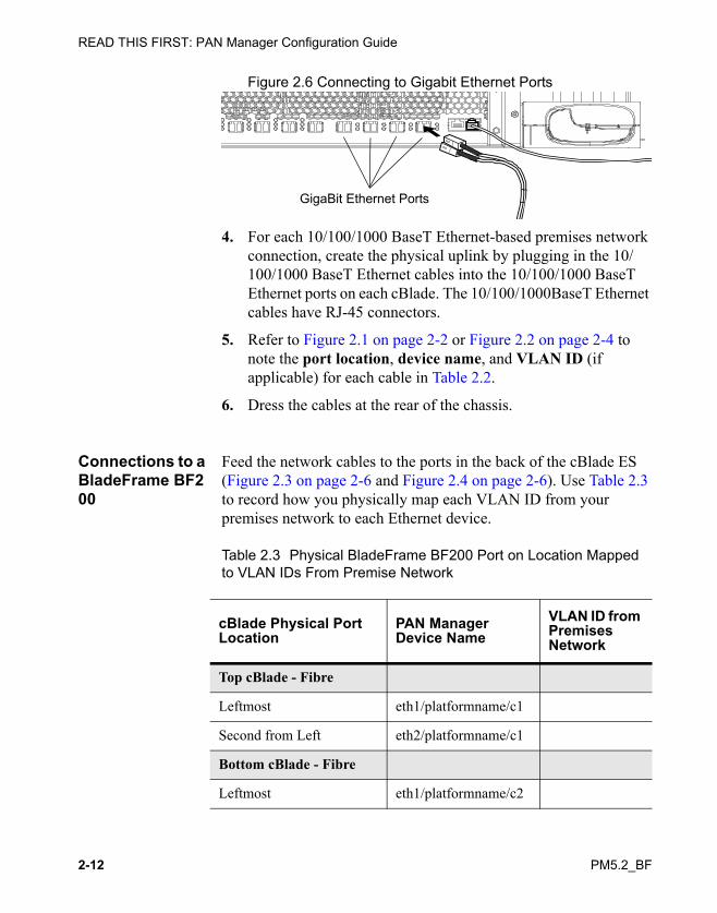
Figure 2.6 Connecting to Gigabit Ethernet Ports
4. For each 10/100/1000 BaseT Ethernet-based premises network connection, create the physical uplink by plugging in the 10/100/1000 BaseT Ethernet cables into the 10/100/1000 BaseT Ethernet ports on each cBlade. The 10/100/1000BaseT Ethernet cables have RJ-45 connectors.
5. Refer to Figure 2.1 on page 2-2 or Figure 2.2 on page 2-4 to note the port location, device name, and VLAN ID (if applicable) for each cable in Table 2.2.
6. Dress the cables at the rear of the chassis.
Connections to a BladeFrame BF200
Feed the network cables to the ports in the back of the cBlade ES (Figure 2.3 on page 2-6 and Figure 2.4 on page 2-6). Use Table 2.3 to record how you physically map each VLAN ID from your premises network to each Ethernet device.
Table 2.3 Physical BladeFrame BF200 Port on Location Mapped to VLAN IDs From Premise Network
GigaBit Ethernet Ports
cBlade Physical Port Location
PAN Manager Device Name
VLAN ID from Premises Network
Top cBlade - Fibre
Leftmost eth1/platformname/c1
Second from Left eth2/platformname/c1
Bottom cBlade - Fibre
Leftmost eth1/platformname/c2

Making BladeFrame Network Connections
PM5.2_BF 2-13
At the end of the installation, give this completed table to the site administrator so they can make appropriate PAN Manager configurations.
Connect your external management network to a BladeFrame BF200 platform:
1. Approach the rear of the cBlade ES chassis, find the BladeFrame BF200 connection panel, and locate the port labelled Management 10/100 Eth0 located between the two Fibre Channel ports and the two GigaBit ETHERNET ports (Figure 2.7).
2. Find the cables (there should be two) leading from your external management network to the installation site.
3. Plug an external management network cable into the port (it requires RJ-45 connector) on each side (C1 and C2) of the BladeFrame BF200 connection panel (Figure 2.7).
Figure 2.7 Connecting to the External Management Ports on the BladeFrame BF200 connection panel
Second from Left eth2/platformname/c2
cBlade Physical Port Location
PAN Manager Device Name
VLAN ID from Premises Network
C2
SERIAL PORT SERIAL PORT
OFF (0)
ON (1)
C1
SCSI 3 SCSI 4 ETH 0 ETH 1 ETH 2
MGMT10/100
SCSI 3 SCSI 4 ETH 0 ETH 1 ETH 2
MGMT10/100
Fibre Channel Fibre Channel GigaBit EthernetGigaBit Ethernet
Management Ports

READ THIS FIRST: PAN Manager Configuration Guide
2-14 PM5.2_BF
Connect the premises network cables to the BladeFrame BF200 network ports:
1. Approach the rear of the cBlade ES chassis, find the BladeFrame BF200 connection panel, and locate the ports labelled GigaBit ETHERNET (Figure 2.8).
Figure 2.8 Connecting to Gigabit Ethernet Ports on the BladeFrame BF200 connection panel
2. Find the cables leading from your Gigabit Ethernet cables (Duplex LC cables) leading from your Premises network switch ports to the installation site.
A pair of cables should extend from each Eth configuration on your Premises network.
3. For each Gigabit Ethernet-based premises network connection, create the physical uplink by plugging in the cables into the Gigabit Ethernet ports on each cBlade (Figure 2.6).
4. Refer to Figure 2.3 on page 2-6 or Figure 2.4 on page 2-6 to note the port location, device name, and VLAN ID (if applicable) for each cable in Table 2.3.
5. Dress the cables at the rear of the chassis.
C2
SERIAL PORT SERIAL PORT
OFF (0)
ON (1)
C1
SCSI 3 SCSI 4 ETH 0 ETH 1 ETH 2
MGMT10/100
SCSI 3 SCSI 4 ETH 0 ETH 1 ETH 2
MGMT10/100
Fibre Channel Fibre Channel GigaBit EthernetGigaBit Ethernet
GigaBit Ethernet Ports

PM5.2_BF 3-1
Chapter 3Making BladeFrame SAN
Connections
This chapter describes how to connect your platform to storage area network (SAN) resources, how to test the connections, and how to configure the HBA ports on the cBlades.
• Layout of SAN Switches
• SAN Connection Requirements
• Connecting SAN Cables to the Platform
Layout of SAN Switches
The procedure for connecting the SAN cables to your cBlades varies slightly, depending on which type of platform you have. Read the section that is appropriate for your platform type.
• Before Connecting SAN Cables to a BladeFrame BF400 S2
• Before Connecting SAN Cables to a BladeFrame BF200

READ THIS FIRST: PAN Manager Configuration Guide
3-2 PM5.2_BF
Before Connecting SAN Cables to a BladeFrame BF400 S2
On the BladeFrame BF400 S2, each cBlade EX is equipped with four QLogic SANBlade 2342 Host Bus Adapters (HBAs). Each cBlade EX requires four SAN cables.
Before plugging the SAN cables into the cBlades, note the location and numbering of the SAN ports (Figure 3.1). The I/O panel on a cBlade EX is located behind the front bezel.
To access the cBlade SAN ports, remove the bezel located on the lower half of the cBlade. To do this, insert a long, slim #1 screwdriver through the slots, loosen the two captive #1 Phillips head screws, and then pull the cover off the guide posts and set it aside.
Figure 3.1 cBlade EX Bezel Removed Showing Fibre Channel and Ethernet Ports
Fibre Channel ports (SCSIn) appear on the left.
Feed the SAN cables through the channel in the chassis behind the glass door, behind the BladeLatch, to the ports in the front of the cBlade EX (Figure 3.1).
SlotsPCI Expansion

Making BladeFrame SAN Connections
PM5.2_BF 3-3
Before Connecting SAN Cables to a BladeFrame BF200
On the BladeFrame BF200, each cBlade ES is equipped with two QLogic SANBlade 2342 Host Bus Adapters (HBAs). Two duplex fibre cables are required per cBlade ES.
Before plugging the SAN cables into the cBlades, note the location and numbering of the SAN ports. Figure 3.2 shows the cBlade ES connection panel layout for the 20-Amp chassis; Figure 3.3 shows the cBlade connection panel layout for the 30-Amp chassis.
Figure 3.2 cBlade ES Ports (20-Amp Chassis)
Figure 3.3 cBlade ES Ports (30-Amp Chassis)

READ THIS FIRST: PAN Manager Configuration Guide
3-4 PM5.2_BF
SAN Connection Requirements
SAN connections to a BladeFrame have the following requirements:
Connection Orientation Requirements
You must install all SAN cables with the transmit (TX) on the cBlade connection to the receive (RX) on the SAN device (Figure 3.4).
Figure 3.4 Fibre Channel Cable Connection Orientation
Cable Requirements
Each SAN connection to the BladeFrame requires cable that meet the following requirements:
• Cable type—Multi-mode Fiber Optic
• Connectors—LC-Type
Note: The SAN connections require an SFP (Small Form Factor Pluggable) connector port interface. The SFP connectors are factory installed and are not hot-swappable. If you have problems with the SFP connectors, contact Fujitsu Technology Solutions customer support or your authorized service vendor.
Record the SCSI Port Numbers
Record which SAN cable you will plug into each physical port (it should have some appropriate label coming from the SAN) in Table 3.1 on page 3-7 or Table 3.2 on page 3-8 (these tables are platform-specific). The WWN associated with each physical port
TxRx
Rx Tx
ControlBlade Fibre Channel
Switch

Making BladeFrame SAN Connections
PM5.2_BF 3-5
connection is important when the site SAN administrator configures WWN interfaces on their platform or when they need to reconnect cables that have been unplugged.
When finished with the installation, you should present this information to the site SAN administrator so they can make appropriate SAN environment configurations.
Connecting SAN Cables to the Platform
After you have determined which SAN devices (switch or array) will be plugged into which ports, you are ready to physically connect the device to its BladeFrame port(s).
Connect Each Fibre Channel Cable to the cBlades:
Caution: Handle the Fibre Channel cable carefully to avoid damaging it.
1. Select the Fibre Channel cable that you want to connect to a cBlade.
2. Align the latches on the connector with the slot in the Fibre Channel port on the cBlade, and plug the Fibre Channel cable into the Fibre Channel port on the cBlade (see Figure 3.5 on page 3-6 or Figure 3.6 on page 3-6).
Warning: When handling Class 1 laser devices and cables, DO NOT look directly into the connector or laser light source, because this could cause serious eye injury or blindness.
!

READ THIS FIRST: PAN Manager Configuration Guide
3-6 PM5.2_BF
Figure 3.5 Connecting to a Fibre Channel Port (cBlade EX)
Figure 3.6 Connecting to a Fibre Channel Port (cBlade ES)
3. Plug the second Fibre Channel cable from the same or another SAN switch into the same Fibre Channel port on the other cBlade.
4. Repeat Step 1 through Step 3 for a second set of Fibre Channel cables, if appropriate, into the ports on both cBlades (Figure 3.5 and Figure 3.6).
Fibre Channel Ports
C2
SERIAL PORT SERIAL PORT
OFF (0)
ON (1)
C1
SCSI 3 SCSI 4 ETH 0 ETH 1 ETH 2
MGMT10/100
SCSI 3 SCSI 4 ETH 0 ETH 1 ETH 2
MGMT10/100
Fibre Channel Fibre Channel GigaBit EthernetGigaBit Ethernet
Fibre Channel Ports
1 2 3 4

Making BladeFrame SAN Connections
PM5.2_BF 3-7
Mapping Physical SAN Ports to a WWN on Each HBA
The platform is physically connected to the site’s SAN environment, but the SAN administrator needs to configure the SAN to recognize each unique WWN for each HBA in this platform. Use Table 3.1 or Table 3.2 (each is platform-specific) to map how each HBA presents its WWN to the SAN fabric. To find the WWNs for the HBAs on your platform you can refer to the WWN paper that was shipped with your platform or replacement cBlade
For additional assistance, contact your customer support representative.
Table 3.1 Physical Port Location Mapped to WWNs From Each HBA on a cBlade EX
cBlade ES Physical HBA Port Location HBA Channel WWN for HBA
C1
Leftmost SCSI4
Second from Left SCSI3
Third from Left SCSI2
Second from Left SCSI1
C2
Leftmost SCSI4
Second from Left SCSI3
Third from Left SCSI2
Second from Left SCSI1

READ THIS FIRST: PAN Manager Configuration Guide
3-8 PM5.2_BF
Table 3.2 Physical Port Location Mapped to WWNs From Each HBA on a cBlade ES
At the end of the installation, give this sheet to the site SAN administrator so they can make appropriate PAN Manager configurations.
cBlade ES Physical HBA Port Location HBA Channel WWN for HBA
C1
Leftmost SCSI3
Second from Left SCSI4
C2
Leftmost SCSI3
Second from Left SCSI4

PM5.2_BF 4-1
Chapter 4Configuring BladeFrame
Power Settings and OtherTasks
This chapter describes how to use the PAN Manager software to configure the platform power settings and other initial tasks.
PIM-B versus PIM-R
The power input modules (Figure 4.1) may be either basic (PIM-B) or redundant (PIM-R). All four must be of the same type.
• The basic PIM is a passive unit with a single attached power cable and no active components.
• The redundant PIM has two attached power cables, which you can connect to two independent power sources. The PIM-R includes firmware to manage status indicators and power-cord failover.

READ THIS FIRST: PAN Manager Configuration Guide
4-2 PM5.2_BF
Figure 4.1 A PIM-B (on left) versus a PIM-R.
If the platform has Basic Power Input Modules (PIM-Bs) (Figure 4.1), you can not configure power settings in PAN Manager. Continue to Chapter 5, “Configuring a Platform After You Complete Physical Connections”.
If the platform has Redundant Power Input Modules (PIM-Rs) (Figure 4.1), continue to the next section.
Configuring Power for BladeFrame BF400 S2s That Have PIM-Rs
Each redundant power input module (PIM-R) connects to two input power sources. The “preferred” power line is used to supply power when both lines are available.
Before configuring the PIM-Rs, determine how you intend to set line preference for each PIM-R:
• If you have easy physical access to the BladeFrame BF400 S2, you can set line preference in either of two ways:
• Use the physical Line Preference Select button on each PIM-R to choose a preferred input power line (Line A or Line B). In order to use the Line Preference Select button, this button must be enabled in PAN Manager.

Configuring BladeFrame Power Settings and Other Tasks
PM5.2_BF 4-3
• Use PAN Manager to set line preference on each PIM-R. (See “Specify the Preferred Power Cord”.)
• If you do not have easy physical access to the BladeFrame BF400 S2, use PAN Manager to set line preference on each PIM-R. (See “Specify the Preferred Power Cord”.)
Specify the Preferred Power Cord
To specify the preferred power cord on BladeFrames that have PIM-Rs:
1. Log on to the PAN Manager GUI via a Web browser. See “Using the PAN Manager GUI” on page 5-8 for details.
2. In the left pane, click Platforms > platform_name.
3. In the right pane, on the Platform platform_name page, select a PIM-R from the Power Domains table.
4. Click the Configure button.
Clear the Enable manual power preference button on physical device check box.
5. In the Configure PIM Settings dialog box, select the preferred power cord (Power Cord A or Power Cord B).
6. Click the Submit button to save your settings and close the dialog box.
When you have selected a preferred power cord, your power configuration tasks are complete. For additional PAN Manager configurations you can make on the platform, see Chapter 5, “Configuring a Platform After You Complete Physical Connections”.

READ THIS FIRST: PAN Manager Configuration Guide
4-4 PM5.2_BF

PM5.2_BF 5-1
Chapter 5Configuring a Platform
After You CompletePhysical Connections
This chapter describes how to configure the BladeFrame using PAN Manager:
• Opening Serial Consoles on the cBlades
• Configuring Unique IP Addresses for PAN Manager and the cBlades and cBlade Hostnames
• Testing Network Connectivity
• Modifying a PAN Manager Internal Network
• Synchronizing the Date and Time with an External Time Source (Recommended, but Optional)
• (Optional) Resetting the PAN Identification
• Testing Physical Connectivity Between the cBlades and the SAN
This chapter assumes the following:
• PM software is running on the platform.
• The cables for SAN and network connections are connected.

READ THIS FIRST: PAN Manager Configuration Guide
5-2 PM5.2_BF
Opening Serial Consoles on the cBlades
Note: This procedure is used throughout the configuration process and is not unique to the task list that follows.
If the platform is not configured on the local network, use a null modem DB9-to-DB9 serial cable with a female connector to connect your laptop directly to a serial port on the cBlade.
If the platform is already configured on the local network, you can open a console on a cBlade remotely instead. See the section “Open a Console on a cBlade Remotely” on page 5-4.
You need a laptop computer with a terminal emulation program installed (such as HyperTerminal on Microsoft Windows or Minicom on Linux).
It is convenient, but not essential, to connect to both cBlades at once, using a second serial cable. If your laptop has only one serial port, you will need a serial-to-USB adapter.
Open a Serial Console on a cBlade
To ensure that your laptop can recognize an external device, be sure the laptop has an adequate power source, such as a standalone power supply unit.
To log on to one or both cBlades using a serial console:
1. Connect the cable from the laptop to the serial port on one cBlade and, optionally, connect the second cable to the serial port on the other cBlade.
On the BladeFrame BF400 S2, the serial port is located in the front of each cBlade EX (Figure 2.2 on page 2-4). On the BladeFrame BF200 the serial port is located on the connection panel in the back of the platform (Figure 2.3 on page 2-6, or Figure 2.4 on page 2-6).

Configuring a Platform After You Complete Physical Connections
PM5.2_BF 5-3
2. Configure your terminal emulation program (such as HyperTerminal) as follows:
Table 5.1 Terminal Settings for a Serial Console on a cBlade
3. With your insertion point in the console window, press Enter. (The cBlade prompt appears in the window if the cBlade is powered on and booted.)
Your cBlade console(s) are now open.
Visually Inspect Cable Connections
The Dell PAN System 3 hardware platform consists of components cabled precisely. An unplugged cable can affect the performance of the platform.
Before doing anything to the system, you must visually inspect the rear of the chassis to ensure that all Ethernet cables and power cables are connected.
Parameter Setting
Bits per second 38400
Data bits 8
Parity (space/mark parity not supported)
None
Stop bits 1
Flow control Xon/Xoff (software)
Terminal, arrow, and control keys
Act as terminal keys
Backspace key Sends delete
Emulation ANSI

READ THIS FIRST: PAN Manager Configuration Guide
5-4 PM5.2_BF
Supply Power Verify that the platform is receiving power by observing each component’s power supply located at the rear of the component. With an appropriate power supply, the two, green power status lights on each power supply remain on.
Caution: If the green power status lights remain dark or the middle yellow status is on, contact your service representative and do not proceed with the initialization.
With power connections established to the Dell PAN System 3, ensure that the [=Vendor chassis model (plats: DBS, DMC)=] and each [=Vendor cBlade model (plats: DRS, DBS, DMC)=] remains powered off at this point in the installation.
Open a Console on a cBlade Remotely
If the platform is already configured on the local network, you can open cBlade console(s) remotely.
Log on to one or both cBlade(s):
1. Select a terminal concentrator port for each connection to your cBlades, and then configure each port as described in Table 5.1.
2. Open a telnet session on your laptop, and connect to the terminal concentrator and the cBlade port, as follows:telnet TermConName TermConPort
where TermConName is the host name or IP address of the terminal concentrator, and TermConPort is the port number of the terminal concentrator’s port that is connected to the cBlade.
3. Press Enter. (The cBlade prompt appears in the window if the cBlade is powered on and booted.)
Your cBlade console(s) are now open.

Configuring a Platform After You Complete Physical Connections
PM5.2_BF 5-5
Configuring Unique IP Addresses for PAN Manager and the cBlades and cBlade Hostnames
Each new platform is configured with default IP addresses for the platform and its cBlades, and default host names for the cBlades. After you complete physical network connections into the platform, you can uniquely configure the platform on your local network as well as make hostname changes to the cBlades that are appropriate for your site.
To configure the platform on your local network, obtain the values for the information in Table 5.2 following information about the platform from your network administrator:
Table 5.2 Installation Information
IP Address or Name Value
PAN Manager (floater) IP address
cBlade 1 IP address
cBlade 2 IP address
Subnet (Network) Mask
Broadcast IP address
Gateway IP Address for External Management Network
Platform name
Hostname of cBlade 1
Hostname of cBlade 2

READ THIS FIRST: PAN Manager Configuration Guide
5-6 PM5.2_BF
To configure the IP addresses for PAN Manager and the cBlades, and the cBlade host names:
1. With PAN Manager running, in a serial console on one of the cBlades (see “Opening Serial Consoles on the cBlades” on page 5-2 for details), enter the following command using the values you have written in Table 5.2:
# extnet -P framemasteripaddr -1 cblade1ipaddr -2 cblade2ipaddr -M networkmaskipaddr -B broadcastipaddr -G gatewayipaddr
where
framemasteripaddr is the new PAN Manager IP addresscblade1ipaddr is the new IP address for cBlade 1cblade2ipaddr is the new IP address for cBlade 2networkmaskipaddr is the new network mask IP addressbroadcastipaddr is the new broadcast IP addressgatewayipaddr is the new gateway IP address
For example, the following:# extnet -P 112.0.5.70 -1 112.0.5.68 -2 112.0.5.69 -B 112.0.5.255 -G 112.0.5.254 -M 255.255.255.0
sets the PAN Manager IP address to 112.0.5.70. It is customary for the cBlade IP addresses to be contiguous with this address. (For additional information about the extnet command, enter man egenera_extnet.)
2. At the warning prompt, enter y.
Upon success, you will see output similar to:Warning: Restarting PAN Manager for external network change.External management network properties set successfully.
3. You do not need to assign new hostnames before you connect the platform to your network. However, you can change the cBlade hostnames to something more meaningful for the installation site than the default hostnames:MyBladeFrame-c1MyBladeFrame-c2
To create a new hostname for each cBlade, in both consoles, enter:

Configuring a Platform After You Complete Physical Connections
PM5.2_BF 5-7
# blade -h hostname platformname/c1# blade -h another_hostname platformname/c2
Note: When you rename cBlades, it is helpful to retain an indication of the cBlade number, such as foo-c1 and foo-c2, where foo is the name of the platform.
4. These hostname changes take effect immediately; you do not need to reboot the cBlades to have them persist.
Testing Network Connectivity
After you configure the platform on your local network, you can use PAN Manager to test your network connection(s).
To test platform network connectivity:
1. From a Linux or Windows workstation on your network, enter the following:# ping PAN_Manager_IP_address
• If you receive a reply to the ping, network connectivity is confirmed.
• If you do not receive a reply to the ping, make sure all connectors are well-seated. If you still do not receive a reply, contact Fujitsu Technology Solutions customer support or your authorized service vendor for assistance.
With the platform powered on and connected to a premises network, you are ready to use PAN Manager. For detailed information see these information resources:
PAN Manager Documentation Set — To learn about the other documents available in the PAN Manager documentation set, see the PAN Manager Release Notes.

READ THIS FIRST: PAN Manager Configuration Guide
5-8 PM5.2_BF
PAN Manager Features — To learn about the PAN Manager features available in the current release, see the PAN Manager Release Notes.
Using the PAN Manager GUI
You can access the PAN Manager software installed on the cBlades using two interfaces: a command line interface (CLI) and a graphical user interface (GUI). While the section “Configuring Unique IP Addresses for PAN Manager and the cBlades and cBlade Hostnames” on page 5-5 shows how to configure the platform on the external network and to rename the cBlades using the PAN Manager CLI, you can use the PAN Manager GUI for most CLI operations. To use the PAN Manager GUI, the platform must be configured to use a local network.
Opening the GUI To open the PAN Manager GUI:
1. Verify that you have a supported web browser. To use the PAN Manager GUI, you must have one of the following:
• Microsoft Internet Explorer 6, or higher
• Mozilla Firefox 1.5, or higher
2. With PAN Manager running, in a serial console on one of the cBlades, determine the PAN Manager IP address of the Dell PAN System for Blades:
a. Log on to either of the cBlades, as described in “Opening Serial Consoles on the cBlades” on page 5-2.
b. Use the extnet command to display the PAN Manager IP address:# extnet
Output similar to the following appears:BladeFrame: MyBladeFrame

Configuring a Platform After You Complete Physical Connections
PM5.2_BF 5-9
Frame Master cBlade1 cBlade2112.0.5.70 112.0.5.68 112.0.5.69
The PAN Manager IP address appears under the label Frame Master; in this example it is 112.0.5.70.
3. Open the web browser, and then enter http://ip_address, where ip_address is the PAN Manager IP address of the Dell PAN System for Blades.
Modifying a PAN Manager Internal Network
PAN Manager uses IP Address-based internal network communication between blades. By changing the IP address of an internal network, the host address for each [=Vendor cBlade model (plats: DRS, DBS, DMC)=] and [=Vendor pBlade model (plats: DRS, DBS, DMC)=] changes. Therefore PAN Manager allocates specific IP addresses which cannot conflict with IP Addresses on the premises network. See Table 5.3 to determine if your premises network will have a conflict with a default PAN Manager Internal Network. If so, use the steps “To modify a PAN Manager internal network:” listed below.
Table 5.3 Default PAN Manager Internal Network IP Addresses
Network Type Subnet Address
Network Mask Address
Broadcast Address
Internal Management Network
192.168.255.0 255.255.255.0 192.168.255.255

READ THIS FIRST: PAN Manager Configuration Guide
5-10 PM5.2_BF
Administrators can modify a PAN Manager Internal Network if the premises network conflicts with a default PAN Manager Internal Network and it is impossible to remove the conflict on the premises network. In this section you use the CLI to modify the default values of an Internal Network as listed in Table 5.3.
Any modification of the internal management network causes a PAN Manager restart which can create temporary outages of the targeted platform.
To modify a PAN Manager internal network:
1. With PAN Manager running, in a serial console on one of the cBlades, log on to the cBlade with a username of root and password of egenera.
2. Use the intnet command to modify a PAN Manager internal network values on the platform:
To modify the Internal Management network settings:# intnet -N networkipaddr -M networkmaskipaddr -B broadcastipaddr -f -t intnet
If you modify the network mask to limit the number of host addresses on the internal management network, you must leave enough capacity for each cBlade and pBlade to have its own IP address.
Synchronizing the Date and Time with an External Time Source (Recommended, but Optional)
The date and time of day were set when you installed the PAN Manager software, and the cBlades synchronize from this time when they boot. If you want to synchronize the time on the platform with the rest of your network (recommended, but optional), you can set up each cBlade to set its time from the same external network time protocol (NTP) server.

Configuring a Platform After You Complete Physical Connections
PM5.2_BF 5-11
To synchronize with external NTP servers:
1. Open a console on either cBlade. See “Opening Serial Consoles on the cBlades” on page 5-2 for details.
2. Log on to the cBlade as root.
3. Disable the /etc/sysconfig/ifc/ntp script by moving or renaming it.
The ntp script overwrites the ntp.conf file with default settings each time the platform restarts. (The default settings synchronize date and time between cBlades, and not with an external time source.) By disabling this script, you ensure that the ntp.conf file is not overwritten with each restart. This ensures that the settings for synchronizing the cBlades with an external time source will persist.
4. Edit the /etc/ntp.conf file to include the NTP servers with which the cBlade is to synchronize.
For more information on working with NTP, see http://www.ntp.org.
5. Restart the NTP service by entering the following:# /etc/rc.d/init.d/ntpd restart
6. Repeat Step 2 through Step 5 for the other cBlade.
(Optional) Resetting the PAN Identification
1. With PAN Manager running, in a serial console on one of the cBlades, log on to the cBlade with a username of root and password of egenera.
2. To modify the platform name, enter:# bframe -n new_platformname [platformname]

READ THIS FIRST: PAN Manager Configuration Guide
5-12 PM5.2_BF
For example, to change the platform name from the default, MyBladeFrame, to PlatformOne, enter:
# bframe -n PlatformOne MyBladeFrame
Configuring PAN Attributes
On a newly installed platform, the Processing Area Network (PAN) name is egenera. You might want to configure the PAN to a name that is unique within the subnet on which the platform is configured, as well as configure information unique to the PAN.
To rename the PAN:
1. With PAN Manager running, in a serial console on one of the cBlades, log on to the cBlade with a username of root and password of egenera.
2. To modify the PAN name, enter:# pan --set-name newpanname
For example, to change the platform name from the default, egenera, to PAN_1, enter:
# pan --set-name PAN_1
To specify PAN identification attributes
Attributes are optional and can be added, modified, or deleted in any order; they can also be entered exclusively instead of as a group. Use the following command syntax to specify the PAN’s identification attributes:
1. With PAN Manager running, in a serial console on one of the cBlades, log on to the cBlade with a username of root and password of egenera.
2. To configure PAN attributes, enter:# pan -L description -o owner -w location

Configuring a Platform After You Complete Physical Connections
PM5.2_BF 5-13
where:
description is a phrase used to identify the PAN. If the description contains spaces, it must be enclosed in double-quotation marks.
owner can be the name of the PAN Administrator or an organization that uses the PAN. If the owner name contains spaces, it must be enclosed in double-quotation marks.
location is the physical location of the PAN and its platform(s). If the location name contains spaces, it must be enclosed in double-quotation marks.
For example, to specify the identification information for a PAN, enter the following:
# pan -L "Data Center PAN" -o "Charlie Gable" -w "7th floor"
where:
-L "Data Center PAN" describes the PAN as the Data Center PAN, -o "Charlie Gable" identifies the owner of the PAN as Charlie Gable, and -w "7th floor" identifies the location of the PAN and platform as the 7th floor.
To configure the SMTP information for the PAN
Administrators can use PAN Manager to configure SMTP for the PAN. Use the following command syntax to specify the PAN’s SMTP attributes:
# smtpsvr -i ip_address -p port -U user -P password -s email_address
where:
ip_address is the IP address of the SMTP mail server at your location.

READ THIS FIRST: PAN Manager Configuration Guide
5-14 PM5.2_BF
port is the port number used by the mail service.
user is the mail server username of the PAN Administrator.
password is the mail server password of the user specified with the -U option.
email_address is the e-mail address from which the PAN Administrator, or the PAN Manager software acting on behalf of the PAN Administrator, can send e-mail messages.
Testing Physical Connectivity Between the cBlades and the SAN
There are two ways to test whether the physical connections are working properly:
• Examine the cBlade Indicator Lights
• Display all SAN Devices
Examine the cBlade Indicator Lights
Adjacent to each Fibre Channel port are LED indicators. Table 5.4 describes what these indicators mean.
Table 5.4 Fibre Channel Port LED Behavior (cBlade)
Yellow LED Green LED
Amber LED Status
(Off) (Off) (Off) Power off
Steady on Steady on Steady on Power on, before firmware init

Configuring a Platform After You Complete Physical Connections
PM5.2_BF 5-15
Display all SAN Devices
After PAN Manager software is running on both cBlades, you can use the PAN Manager san command to further test your connection(s).
To verify that you have physically integrated the platform into the SAN correctly, use PAN Manager to display the storage devices that are visible to the cBlades.
To test SAN connectivity:
1. Open a console on a cBlade. See “Opening Serial Consoles on the cBlades” on page 5-2 for details.
2. Log on to the cBlade as root.
3. At the prompt, enter# san
to display a list of all storage devices visible to the cBlade.
• If you see a list of available devices, SAN connectivity is confirmed.
Flashing Flashing Flashing Flashing together: Power on, after firmware init, or “beacon”
Flashing alternately: Firmware error
(Off) (Off) Steady on/Flashing
Online, 1 Gbps link / I/O activity
(Off) Steady on/Flashing
(Off) Online, 2 Gbps link / I/O activity
Steady on/Flashing
(Off) (Off) Online, 4 Gbps link / I/O activity
Yellow LED Green LED
Amber LED Status

READ THIS FIRST: PAN Manager Configuration Guide
5-16 PM5.2_BF
• If you do not see a list of devices, make sure all connectors are well-seated. If you still do not see a list of devices, contact Fujitsu Technology Solutions customer support or your authorized service vendor for assistance.
After you physically connect the platform to a local SAN environment and the SAN administrator has configured the SAN to recognize each unique WWN for each HBA in this platform, there may be additional setup steps, as described in PAN Manager SAN Integration Guide.

PM5.2_BF
Appendixes
This part of the guide covers miscellaneous information regarding platform hardware. Appendixes include:
• Appendix A, “Adding or Replacing Processing Blades”
• Appendix B, “BladeFrame Environmental Requirements”
• Appendix C, “BladeFrame Power Status Indicators”

PM5.2_BF A-1
Appendix AAdding or Replacing
Processing Blades
This chapter describes how to add or replace a Processing Blade (pBlade). Topics include:
• Adding a pBlade
• Replacing a pBlade
• Reinserting a Removed pBlade
• Failing a pServer Back to its Original pBlade
Note: If you need to replace Control Blades, contact Fujitsu Technology Solutions customer support.

READ THIS FIRST: PAN Manager Configuration Guide
A-2 PM5.2_BF
Adding a pBlade
If your platform was not fully populated with pBlades when you purchased it, at some point you might need to add new pBlades. The platform can remain powered on and fully operational while you add new pBlades.
The chassis comes with filler blades occupying the empty slots. Remove the filler blade in the slot that will receive the new pBlade.
To remove a filler blade:
1. Push on the end of the filler blade’s finger-pull. The finger pull swivels out.
2. Place a finger in the finger-pull and pull the filler blade all the way out. (Filler blades do not have safety latches.)
To insert a pBlade:
1. Align the pBlade rails with the chassis rails in the desired slot.
2. Push the pBlade into the chassis until its BladeLatch “pops” out from the face of the pBlade.
Note: Be sure to push on the front bezel and not on the BladeLatch itself.
3. Firmly push the BladeLatch back into the face of the bezel until it stops.
4. Release the BladeLatch and allow it to spring back until it is flush (or near flush) with the front of the pBlade.
Warning: Place the pBlade in the chassis with care. Find additional physical assistance if necessary to ensure that you insert the pBlade in a controlled manner.
!

PM5.2_BF A-3
Note: If the BladeLatch handle does not remain flush with the front of the pBlade, the pBlade is defective and should be returned.
When a pBlade is recognized by PAN Manager, it is available for allocation to an LPAN. When the pBlade is eventually booted, its indicator light changes to steady blue, indicating that it is in use.
Replacing a pBlade
You can replace an existing pBlade at any time without powering down the platform. However, if the pBlade is currently hosting an active pServer (the indicator light associated with this pBlade is solid blue), you should shut down the pServer before removing the pBlade from the chassis.
This section describes how to:
• Select (identify) a pBlade to remove.
• Remove an inactive pBlade.
• Shut down an active pServer and then remove the pBlade.
• Shut down or failover applications on an active pServer, shut down the pServer, and then remove the pBlade.
Selecting the pBlade for Removal
You can change the state of the pBlade to selected to make it easier to identify the blade to be removed. Selecting a pBlade does not kill processes, shut down the pServer, or power down the pBlade. Selecting a pBlade only changes the indicator light to blinking blue. It does not affect the processing of the pBlade.
To select a pBlade:
1. In the left pane of the PAN Manager GUI, open the Resources tree and click Blades.

READ THIS FIRST: PAN Manager Configuration Guide
A-4 PM5.2_BF
2. On the Blades page, click the pBlade you want to remove.
3. At the bottom of the pBlade name page, click the Select icon (the checkmark).
Note: If you select and remove a pBlade and then insert another into the same slot, the indicator light remains blinking blue. You must unselect the pBlade in the PAN Manager GUI.
Removing an Inactive pBlade
If a pServer is not currently active on the pBlade that you want to remove (the indicator light is solid amber), you can select the pBlade and then remove it.
To remove a pBlade:
1. Open the BladeLatch to unlock the pBlade.
2. Slide the pBlade out until you see the metal safety catch.
3. Press the metal safety catch down.
4. Slide the pBlade out of the slot.
Shutting Down an Active pServer
If a pServer is active on the pBlade you want to remove, you must shut down the pServer before removing the pBlade.
If a high-availability application is running on the pServer, you should stop the application or (if desired) move or failover the application to another pServer.
To shut down a pServer:
1. On the pServer Dashboard, click the Shutdown icon (the down arrow) next to the pServer you want to shut down.
Warning: Place the pBlade in the chassis with care. Find additional physical assistance if necessary to ensure that you insert or remove the pBlade in a controlled manner.
!

PM5.2_BF A-5
To control a high-availability application:
1. In the left pane, click LPANs > LPANname > High Availability.
2. In the High Availability for LPAN LPANname page, in the Applications area, click the Applicationname that you want to control.
3. On the bottom border of this Application Applicationname page, in the Controls area, you can use the following control buttons:
• Click to start this application.
• Click to stop this application.
• Click to move this application to a booted pServer specified in its failover policy configuration or back to its primary pServer, if available.
• Click to run the application’s executable resource(s).
Note: If an action is currently prohibited on the application, the button is shaded.
Reinserting a Removed pBlade
You can move a pBlade to a different slot in the chassis or insert a new or repaired pBlade into a slot previously vacated.
To do so, follow the instructions to shut down any active pServers on the pBlade and then remove the pBlade from the slot. See “Shutting Down an Active pServer” on page A-4 and “Removing an Inactive pBlade” on page A-4.
You need to wait at least 30 seconds between removing a pBlade and reinserting it to allow the Control Blade to update its information on the status of the target slot.

READ THIS FIRST: PAN Manager Configuration Guide
A-6 PM5.2_BF
Failing a pServer Back to its Original pBlade
To fail back a pServer to its original pBlade, you must release its resources, and then reboot the pServer.

PM5.2_BF B-1
Appendix BBladeFrame
EnvironmentalRequirements
The platform requires the environmental limits listed in Table B.1.
Table B.1 Environmental Requirements
System air flow direction is from front to back, with no air filters.
Air movers are sensed for rotational operation and reported to PAN Manager in case of failure. Ambient temperature is also monitored and can be reported through PAN Manager.
Specification Range
Operating temperature 41F to 95F (5C to 35C)
Maximum altitude 6000 feet
Humidity range 10-80% noncondensing
Acoustics Computer room/data center compatible

READ THIS FIRST: PAN Manager Configuration Guide
B-2 PM5.2_BF
Note: For detailed information and data center layout suggestions, see the Technical White Paper entitled Deploying BladeFrames in Enterprise Data Centers. This paper is available from http://support.ts.fujitsu.com.

PM5.2_BF C-1
Appendix CBladeFrame Power Status
Indicators
This appendix describes the indicator lights on the front of the BladeFrame that show the status of each blade during power on and normal operation. It also describes the LED status indicators on the redundant (PIM-R) power modules, if applicable. (There are no LED indicators on the basic (PIM-B) power modules.)
Understanding Blade Indicator Lights
BladeFrame indicator lights show the operating status of a blade.
If you insert or reseat a blade, it first receives power. Next, it is recognized by PAN Manager software. Finally, it executes instructions. These changes in a blade’s state are visible in the indicator light on the front panel (see Table C.1).

READ THIS FIRST: PAN Manager Configuration Guide
C-2 PM5.2_BF
Table C.1 Blade Indicator Light Status
PAN Manager recognizes and confirms a change in blade status before the indicator light reflects the change. This frequently results in a delay between actual status change and the associated light change.
Understanding PIM-R Indicator Lights
A BladeFrame BF400 S2 that is equipped with redundant Power Input Modules (PIM-Rs) allows you to attach the platform to independent power feeds. On a BladeFrame BF400 S2 that has PIM-Rs, you can use PAN Manager to monitor and manage power. (By contrast, the basic PIM (PIM-B) is a passive power unit and is not configurable through software.)
On a BladeFrame BF400 S2 that has PIM-Rs, you can also use the Line Preference Select Switch (see Figure C.1) on the back of the PIM-R to set the line source and line preference, if this feature is
Appearance Status Meaning
Blinking amber Standby The blade has been successfully inserted into the chassis and is receiving standby power.
Steady amber Recognized PAN Manager software, running on the Control Blade, was able to contact the blade through the BladePlane.
Steady blue Active Processing Blade — The Processing Blade is executing software instructions.
Control Blade — The Control Blade is running PAN Manager software.
Blinking blue Selected An administrator has designated the blade as ready for an administrative action. A Processing Blade that is selected can be either active or inactive.

PM5.2_BF C-3
enabled in PAN Manager. See Chapter 4, “Configuring BladeFrame Power Settings and Other Tasks” for complete instructions for configuring power.
Figure C.1 PIM-R Indicator Lights
The LEDs on the back of the PIM-R show which power source is selected and in use (A or B) and the system status of the PIM-R (see Table C.2).
Table C.2 PIM-R LED Status
Line Status
Line Active
Line Preference
Line Preference Select
PIM On / SelectedPIM Control
LineA
LineB
LED Label Color Meaning
Line Status Green The data center power connection to the PIM-R power cord meets the requirements of the platform.
If the LED is off, the power does not meet the platform requirements.
Line Active Green The BladeFrame is using that input as the power source.
Line Preference
Green The power input (A or B) has been selected as the primary power source.
If both LEDs are off, no preference has been set.
PIM On / Selected
Blinking blue
The PIM-R has been selected by PAN Manager for replacement or servicing.

READ THIS FIRST: PAN Manager Configuration Guide
C-4 PM5.2_BF
Steady blue
The PIM-R has been programmed and is fully functional. Removal of the PIM-R in this state will cause the BladeFrame to fail.
PIM Control Blinking amber
The PIM-R is connected to the BladeFrame and the power supply but has not yet been recognized by PAN Manager.
Steady amber
The PIM-R is communicating with the BladeFrame through the system software but PAN Manager has not yet programmed the PIM.
LED Label Color Meaning

Index-1
A
active blade state C-2adding
pBlades to a BladeFrame A-2amber light C-2Assigned name 5-5
B
blade state A-3blade states C-2BladeFrame
modifying hardware A-2BladeFrame EX cabling
connecting the external management network 2-10, 2-13
blue light C-2Broadcast address, configuring IP
Address 5-6
C
cablingconnecting the network 2-9
connecting the premises network 2-11, 2-14
configuringSMTP 5-13
connecting network cables 2-9connecting premises network cables
2-10, 2-11, 2-13, 2-14connectivity testing 5-7
E
Ethernet10/100BaseT cabling 2-7, 2-10,
2-13Gigabit connection on BladeFrame
ES 2-7Gigabit connection on BladeFrame
EX 2-3Gigabit connection requirements
2-8Gigabit connections 2-8
external management networkconnecting 2-10, 2-13
Index

READ THIS FIRST: PAN Manager Configuration Guide
Index-2
G
Gateway address, configuring IP Address 5-6
Gigabit Ethernet connection on BladeFrame EX 2-11, 2-14
H
hostnamesetting new 5-6
I
indicator lights C-1Information required for installation
5-5IP addresses 5-5
L
LED indicators on BladeFrame ES 2-7LED indicators on BladeFrame EX 2-4
M
modifyingBladeFrame hardware A-2
N
networkconnecting 2-9
Network mask, configuring IP Address 5-6
ntp.conf 5-11
ntpd 5-11null modem serial cable 1-4
P
PANconfiguring SMTP 5-13
PAN Manager, configuring IP Address 5-6
pBladeadding A-2failing back to original pBlade A-6reinserting into chassis A-5replacing A-2, A-3selecting A-3
ping command 5-7port numbers 2-8, 3-4premises network
connecting 2-11, 2-14prerequisites 1-4
R
recognized blade state C-2replacing
pBlade A-2, A-3RJ-45 connector 2-12
S
selected blade state A-3, C-2selecting
pBlade A-3serial console
configuring PAN Manager from 5-6, 5-8, 5-10, 5-11, 5-12

Index
Index-3
SFP -Small Form Factor Pluggable on BladeFrame ES 2-7
SFP -Small Form Factor Pluggable on BladeFrame EX 2-4, 3-4
SMTP 5-13smtpsvr command 5-13standby blade state C-2synchronizing time, NTP servers 5-11

READ THIS FIRST: PAN Manager Configuration Guide
Index-4