Reactor Design
48
Reactor Design S,S&L Chapter 7 Terry A. Ring ChE
-
Upload
guillermococha -
Category
Documents
-
view
53 -
download
3
Transcript of Reactor Design
Reactor Design
S,S&L Chapter 7
Terry A. Ring
ChE

Reactor Types
• Ideal– PFR– CSTR
• Real– Unique design geometries and therefore RTD– Multiphase– Various regimes of momentum, mass and
heat transfer

Reactor Cost
• Reactor is– PRF
• Pressure vessel
– CSTR• Storage tank with mixer• Pressure vessel
– Hydrostatic head gives the pressure to design for

Reactor Cost
• PFR– Reactor Volume (various L and D) from reactor
kinetics– hoop-stress formula for wall thickness:
– • t= vessel wall thickness, in.• P= design pressure difference between inside and outside of
vessel, psig• R= inside radius of steel vessel, in.• S= maximum allowable stress for the steel. • E= joint efficiency (≈0.9)• tc=corrosion allowance = 0.125 in.
ctPSE
PRt
6.0

Reactor Cost
• Pressure Vessel – Material of Construction gives ρmetal
– Mass of vessel = ρmetal (VC+2VHead)• Vc = πDL
• VHead – from tables that are based upon D
– Cp= FMCv(W)

Reactors in Process Simulators
• Stoichiometric Model– Specify reactant conversion and extents of
reaction for one or more reactions• Two Models for multiple phases in
chemical equilibrium• Kinetic model for a CSTR• Kinetic model for a PFR• Custom-made models (UDF)
Used in early stages of design

Kinetic Reactors - CSTR & PFR
• Used to Size the Reactor• Used to determine the reactor dynamics• Reaction Kinetics
/)exp()(
)(1
RT
EkTk
CTkdt
dCr
Ao
C
ii
jj
i

PFR – no backmixing
• Used to Size the Reactor
• Space Time = Vol./Q• Outlet Conversion is used for flow sheet
mass and heat balances
kX
kko r
dXFV
0

CSTR – complete backmixing
• Used to Size the Reactor
• Outlet Conversion is used for flow sheet mass and heat balances
k
kko
r
XFV

Review : Catalytic Reactors – Brief Introduction
Major Steps
A B
ABulk Fluid
External Surfaceof Catalyst Pellet
Catalyst Surface
Internal Surfaceof Catalyst Pellet
CAb
CAs
2. Defined by an Effectiveness Factor
1. External DiffusionRate = kC(CAb – CAS)
3. Surface AdsorptionA + S <-> A.S
4. Surface Reaction5. Surface DesorptionB. S <-> B + S
6 . Diffusion of products from interior to pore mouth
B
7 . Diffusion of products from pore mouth to bulk

Catalytic Reactors
• Various Mechanisms depending on rate limiting step• Surface Reaction Limiting• Surface Adsorption Limiting• Surface Desorption Limiting• Combinations
– Langmuir-Hinschelwood Mechanism (SR Limiting)
• H2 + C7H8 (T) CH4 + C6H6(B)
TB
HTT pp
ppkr
04.139.112

Catalytic Reactors – Implications on design
1. What effects do the particle diameter and the fluid velocity above the catalyst surface play?
2. What is the effect of particle diameter on pore diffusion ?3. How the surface adsorption and surface desorption influence the rate law?4. Whether the surface reaction occurs by a single-site/dual –site / reaction
between adsorbed molecule and molecular gas?5. How does the reaction heat generated get dissipated by reactor design?

Enzyme Catalysis
• Enzyme Kinetics
• S= substrate (reactant)• E= Enzyme (catalyst)
OHS
SEOHs CkkCk
CCCkkr
2
2
321
31

Problems
• Managing Heat effects• Optimization
– Make the most product from the least reactant
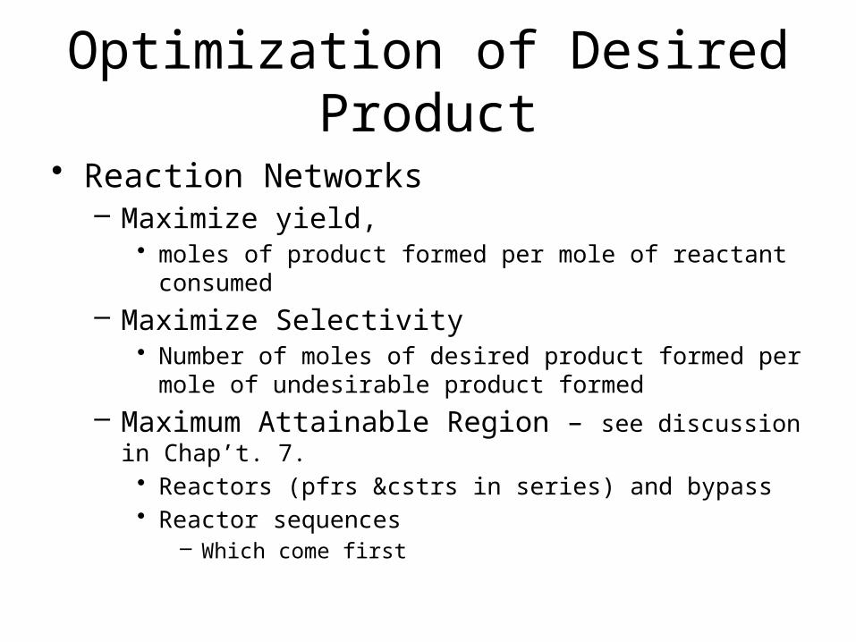
Optimization of Desired Product
• Reaction Networks– Maximize yield,
• moles of product formed per mole of reactant consumed
– Maximize Selectivity• Number of moles of desired product formed per mole of
undesirable product formed
– Maximum Attainable Region – see discussion in Chap’t. 7.• Reactors (pfrs &cstrs in series) and bypass • Reactor sequences
– Which come first

Managing Heat Effects
• Reaction Run Away– Exothermic
• Reaction Dies– Endothermic
• Preventing Explosions• Preventing Stalling

Temperature Effects
• On Equilibrium• On Kinetics

Equilibrium Reactor-Temperature Effects
• Single Equilibrium• aA +bB rR + sS
– ai activity of component I• Gas Phase, ai = φiyiP,
– φi== fugacity coefficient of i• Liquid Phase, ai= γi xi exp[Vi (P-Pi
s) /RT]– γi = activity coefficient of i – Vi =Partial Molar Volume of i
2
ln,exp
RT
H
dT
Kd
RT
G
aa
aaK
orxneq
orxn
aB
aA
sS
rR
eq
Van’t Hoff eq.

Overview of CRE – Aspects related to Process Design
1. Levenspiel , O. (1999), “Chemical Reaction Engineering”, John Wiley and Sons , 3rd ed.
Le Chatelier’s Principle

Unfavorable Equilibrium
• Increasing Temperature Increases the Rate
• Equilibrium Limits Conversion

Overview of CRE – Aspects related to Process Design
1. Levenspiel , O. (1999), “Chemical Reaction Engineering”, John Wiley and Sons , 3rd ed.

Feed Temperature, ΔHrxn
Heat Balance over Reactor
CoolingAdiabatic
Adiabatic
Q = UA ΔTlm

Reactor with Heating or Cooling
Q = UA ΔT

Kinetic Reactors - CSTR & PFR – Temperature Effects
• Used to Size the Reactor• Used to determine the reactor dynamics• Reaction Kinetics
RT
EkTk
CTkdt
dCr
Ao
C
ii
jj
i
exp)(
)(1

PFR – no backmixing
• Used to Size the Reactor
• Space Time = Vol./Q• Outlet Conversion is used for flow sheet
mass and heat balances
kX
kko r
dXFV
0

CSTR – complete backmixing
• Used to Size the Reactor
• Outlet Conversion is used for flow sheet mass and heat balances
k
kko
r
XFV

Unfavorable Equilibrium
• Increasing Temperature Increases the Rate
• Equilibrium Limits Conversion

Various Reactors, Various Reactions
kX
kko r
dXFV
0
k
kko
r
XFV

Reactor with Heating or Cooling
Q = UA ΔT

Temperature Profiles in a Reactor
Exothermic Reaction
Recycle

Best Temperature Path

Optimum Inlet TemperatureExothermic Rxn

Managing Heat Effects
• Reaction Run Away– Exothermic
• Reaction Dies– Endothermic
• Preventing Explosions• Preventing Stalling

Inter-stage Cooler
Exothermic Equilibria
Lowers Temp.

Inter-stage Cold Feed
Exothermic Equilibria
Lowers TempLowers Conversion

Optimization of Desired Product
• Reaction Networks– Maximize yield,
• moles of product formed per mole of reactant consumed
– Maximize Selectivity• Number of moles of desired product formed per mole of
undesirable product formed
– Maximum Attainable Region – see discussion in Chap’t. 6.• Reactors and bypass • Reactor sequences

Reactor Design for Selective Product Distribution
S,S&L Chapt. 7

Overview
• Parallel Reactions– A+BR (desired)– AS
• Series Reactions– ABC(desired)D
• Independent Reactions– AB (desired)– CD+E
• Series Parallel Reactions– A+BC+D– A+CE(desired)
• Mixing, Temperature and Pressure Effects

Examples
• Ethylene Oxide Synthesis• CH2=CH2 + 3O22CO2 + 2H2O
• CH2=CH2 + O2CH2-CH2(desired)
O
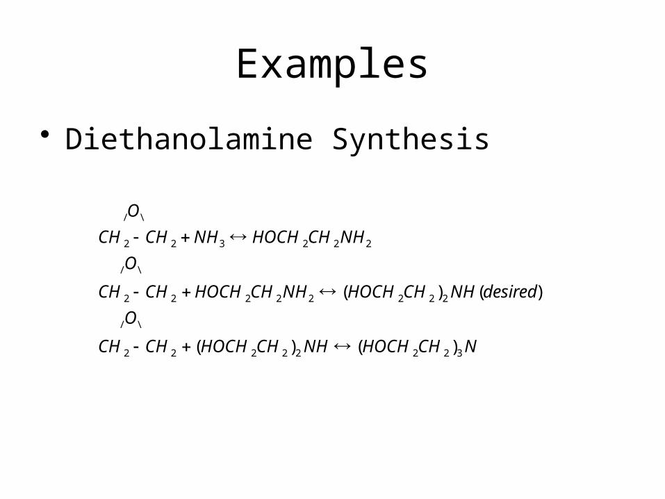
Examples
• Diethanolamine Synthesis
NCHHOCHNHCHHOCHCHCH
O
desiredNHCHHOCHNHCHHOCHCHCH
O
NHCHHOCHNHCHCH
O
32222222
\/
22222222
\/
222322
\/
)()(
)()(

Examples
• Butadiene Synthesis, C4H6, from Ethanol
OHHCCHOCHHC
HCHOCHOHHC
OHHCOHHC
264342
2352
24252

Rate Selectivity
• Parallel Reactions– A+BR (desired)– A+BS
• Rate Selectivity
• (αD- αU) >1 make CA as large as possible• (βD –βU)>1 make CB as large as possible
• (kD/kU)= (koD/koU)exp[-(EA-D-EA-U)/(RT)]– EA-D > EA-U T– EA-D < EA-U T
)()(A
U
Drr
D/UD
U
D Ck
kS UDU
BC

Reactor Design to Maximize Desired Product for Parallel Rxns.

Maximize Desired Product
• Series Reactions– AB(desired)CD
• Plug Flow Reactor• Optimum Time in Reactor

Fractional Yield
OHCOOCHOCH
OHCHOCHOgOHCHCH
2223
23223
222
52
1)(
(k2/k1)=f(T)

Real Reaction Systems
• More complicated than either – Series Reactions– Parallel Reactions
• Effects of equilibrium must be considered• Confounding heat effects• All have Reactor Design Implications
Engineering Tricks
• Reactor types– Multiple Reactors
• Mixtures of Reactors– Bypass– Recycle after Separation
• Split Feed Points/ Multiple Feed Points• Diluents• Temperature Management with interstage
Cooling/Heating

A few words about simulators
• Aspen• Kinetics
– Must put in with “Aspen Units”• Equilibrium constants
– Must put in in the form
lnK=A+B/T+CT+DT2
• ProMax• Reactor type and Kinetics must match!!• Kinetics
– Selectable units• Equilibrium constants