REACTOR™ 40 COMPACT HYDRAULIC • Cable ties...
12
REACTOR™ 40 COMPACT HYDRAULIC Installation Instructions Important Safety Information WARNING See the Important Safety and Product Information guide in the product box for product warnings and other important information. You are responsible for the safe and prudent operation of your vessel. The autopilot is a tool that enhances your capability to operate your boat. It does not relieve you of the responsibility of safely operating your boat. Avoid navigational hazards and never leave the helm unattended. Always be prepared to promptly regain manual control of your boat. Learn to operate the autopilot on calm and hazard-free open water. Use caution when operating the autopilot near hazards in the water, such as docks, pilings, and other boats. CAUTION When in use, beware of hot motor and solenoid components and the risk of entrapment from moving parts. Failure to install and maintain this equipment in accordance with these instructions could result in damage or injury. NOTICE To avoid damage to your boat, the autopilot system should be installed by a qualified marine installer. Specific knowledge of hydraulic steering componentry and marine electrical systems is required for proper installation. Registering Your Device Help us better support you by completing our online registration today. Keep the original sales receipt, or a photocopy, in a safe place. 1 Go to garmin.com/express . 2 Sign in to your Garmin ® account. Installation Preparation The autopilot system consists of multiple components. You should familiarize yourself with all of the component mounting and connection considerations before beginning installation. You must know how the components operate together in order to correctly plan the installation on your boat. You can consult the layout diagrams (Power and Data Layout, page 2) to help understand the mounting and connection considerations. You should lay out all of the components on the boat as you plan the installation to make sure your cables will reach each component. If needed, extension cables (sold separately) for various components are available from your Garmin dealer or from www.garmin.com. You should record the serial number of each component for registration and warranty purposes. Tools Needed • Safety glasses • Drill and drill bits • Wrenches • 90 mm (3.5 in.) hole saw or a rotary cutting tool (for installing an optional helm control) • Wire cutters/strippers • Phillips and flat screwdrivers • Cable ties • Single Pole Single Throw (SPST) switch (to use as an autopilot bypass when not installing the Shadow Drive ™ valve) • Waterproof wire connectors (wire nuts) or heat-shrink tubing and a heat gun • Marine sealant • Marine corrosion inhibitor spray • Portable or handheld compass (to test for magnetic interference) • Hydraulic hose with machine-crimped or field-replaceable fittings that have a minimum rating of 1000 psi • Hydraulic T-fittings • Hydraulic fluid • Thread sealant • Hydraulic bleeding equipment NOTE: Mounting screws are provided for the main components of the autopilot system. If the provided screws are not appropriate for the mounting surface, you must provide the correct types of screws. Mounting and Connection Considerations The autopilot components connect to each other and to power using the included cables. Ensure that the correct cables reach each component and that each component is in an acceptable location before mounting or wiring any components. CCU Mounting and Connection Considerations • The CCU is the primary sensor of the Reactor 40 Compact Hydraulic autopilot system. For best performance, observe these considerations when selecting a mounting location. ◦ A handheld compass should be used to test for magnetic interference in the area where the CCU is to be mounted(Testing a Location for Magnetic Interference, page 2). ◦ The CCU should be mounted on a rigid surface for best performance. • Mounting screws are provided with the CCU. If you use mounting hardware other than the provided screws, the hardware must be quality stainless or brass material to avoid magnetic interference with the CCU. Test any mounting hardware with a handheld compass to make sure no magnetic fields are present in the hardware. • The CCU cable connects the CCU to the ECU and is 5 m (16 ft.) long. ◦ If the CCU cannot be mounted within 5 m (16 ft.) of the ECU, extension cables are available from your local Garmin dealer or at www.garmin.com. ◦ This cable must not be cut. Finding the Best Mounting Location 1 Create a list of all suitable mounting locations for the CCU. Suitable mounting locations should not be within 60 cm (2 ft.) of the following: • Iron • Magnets • High-current wires • Intermittently-running pumps, such as head pumps and live well pumps A large magnet, such as a subwoofer-speaker magnet, should be no closer than 1.5 m (5 ft.) to any of the mounting locations. October 2017 190-02316-02_0A
-
Upload
trinhthuan -
Category
Documents
-
view
214 -
download
1
Transcript of REACTOR™ 40 COMPACT HYDRAULIC • Cable ties...

REACTOR™ 40 COMPACT HYDRAULIC
Installation InstructionsImportant Safety Information
WARNINGSee the Important Safety and Product Information guide in the product box for product warnings and other important information.You are responsible for the safe and prudent operation of your vessel. The autopilot is a tool that enhances your capability to operate your boat. It does not relieve you of the responsibility of safely operating your boat. Avoid navigational hazards and never leave the helm unattended.Always be prepared to promptly regain manual control of your boat.Learn to operate the autopilot on calm and hazard-free open water.Use caution when operating the autopilot near hazards in the water, such as docks, pilings, and other boats.
CAUTIONWhen in use, beware of hot motor and solenoid components and the risk of entrapment from moving parts.Failure to install and maintain this equipment in accordance with these instructions could result in damage or injury.
NOTICETo avoid damage to your boat, the autopilot system should be installed by a qualified marine installer. Specific knowledge of hydraulic steering componentry and marine electrical systems is required for proper installation.
Registering Your DeviceHelp us better support you by completing our online registration today. Keep the original sales receipt, or a photocopy, in a safe place.1 Go to garmin.com/express .2 Sign in to your Garmin® account.
Installation PreparationThe autopilot system consists of multiple components. You should familiarize yourself with all of the component mounting and connection considerations before beginning installation. You must know how the components operate together in order to correctly plan the installation on your boat.You can consult the layout diagrams (Power and Data Layout, page 2) to help understand the mounting and connection considerations.You should lay out all of the components on the boat as you plan the installation to make sure your cables will reach each component. If needed, extension cables (sold separately) for various components are available from your Garmin dealer or from www.garmin.com.You should record the serial number of each component for registration and warranty purposes.
Tools Needed• Safety glasses• Drill and drill bits• Wrenches• 90 mm (3.5 in.) hole saw or a rotary cutting tool (for installing
an optional helm control)
• Wire cutters/strippers• Phillips and flat screwdrivers• Cable ties• Single Pole Single Throw (SPST) switch (to use as an
autopilot bypass when not installing the Shadow Drive™
valve)• Waterproof wire connectors (wire nuts) or heat-shrink tubing
and a heat gun• Marine sealant• Marine corrosion inhibitor spray• Portable or handheld compass (to test for magnetic
interference)• Hydraulic hose with machine-crimped or field-replaceable
fittings that have a minimum rating of 1000 psi• Hydraulic T-fittings• Hydraulic fluid• Thread sealant• Hydraulic bleeding equipmentNOTE: Mounting screws are provided for the main components of the autopilot system. If the provided screws are not appropriate for the mounting surface, you must provide the correct types of screws.
Mounting and Connection ConsiderationsThe autopilot components connect to each other and to power using the included cables. Ensure that the correct cables reach each component and that each component is in an acceptable location before mounting or wiring any components.CCU Mounting and Connection Considerations• The CCU is the primary sensor of the Reactor 40 Compact
Hydraulic autopilot system. For best performance, observe these considerations when selecting a mounting location.◦ A handheld compass should be used to test for magnetic
interference in the area where the CCU is to be mounted(Testing a Location for Magnetic Interference, page 2).
◦ The CCU should be mounted on a rigid surface for best performance.
• Mounting screws are provided with the CCU. If you use mounting hardware other than the provided screws, the hardware must be quality stainless or brass material to avoid magnetic interference with the CCU.Test any mounting hardware with a handheld compass to make sure no magnetic fields are present in the hardware.
• The CCU cable connects the CCU to the ECU and is 5 m (16 ft.) long.◦ If the CCU cannot be mounted within 5 m (16 ft.) of the
ECU, extension cables are available from your local Garmin dealer or at www.garmin.com.
◦ This cable must not be cut.Finding the Best Mounting Location1 Create a list of all suitable mounting locations for the CCU.
Suitable mounting locations should not be within 60 cm (2 ft.) of the following:• Iron• Magnets• High-current wires• Intermittently-running pumps, such as head pumps and
live well pumpsA large magnet, such as a subwoofer-speaker magnet, should be no closer than 1.5 m (5 ft.) to any of the mounting locations.
October 2017190-02316-02_0A

2 Locate the center of rotation of the boat, and measure the distance between the center of rotation and each of the suitable mounting locations you listed in step 1.
3 Select the location closest to the center of rotation.If more than one location is approximately the same distance from the center of rotation, you should select the location that best meets these considerations.• The best location is closest to the centerline of the boat.• The best location is lower in the boat.• The best location is slightly forward in the boat.
Testing a Location for Magnetic InterferenceYou can use a handheld compass to test a mounting location for magnetic interference.1 Hold a handheld compass in the CCU mounting location.2 Move the compass six inches to the left of the location, then
six inches to the right, observe the needle, and select an action:• If the compass needle moves more than three degrees
during this step, magnetic interference is present. Select a new mounting location and repeat the test.
• If the compass needle does not move, or moves less than three degrees, proceed to the next step.
3 Repeat this process while moving the compass above and below the mounting location.
4 Repeat this process while moving the compass in front of and behind the mounting location.
ECU Mounting and Connection Considerations• The ECU can be mounted on a flat surface, facing any
direction.• Mounting screws are included with the ECU, but you may
need to provide different screws if the supplied screws are not suitable for the mounting surface.
• The ECU must be mounted within 0.5 m (19 in.) of the pump.◦ The cables connecting the ECU to the pump cannot be
extended.• The ECU must be mounted in a location where it will not be
submerged or exposed to wash down.• The ECU power cable connects to the boat battery, and it
can be extended if needed (Power Cable Extensions, page 5).
Pump Mounting ConsiderationsConsult the hydraulic-layout diagrams in these instructions to help determine the pump-installation location (Hydraulic Layouts, page 4).• The pump must be mounted at a location to which you can
extend the hydraulic steering lines of the boat.• The pump should be mounted horizontally if possible.• If the pump must be mounted vertically, with the hydraulic
connections facing upward.Shadow Drive Mounting ConsiderationsNOTE: The Shadow Drive is a sensor you install in the hydraulic steering lines of your boat. It detects when you manually take control of the helm and suspends autopilot control of the boat.NOTE: If your autopilot package does not include a Shadow Drive, you should install a manual switch to disable the autopilot if needed.• The Shadow Drive must be mounted horizontally and as level
as possible, with cable ties firmly securing it in place.• The Shadow Drive must be mounted at least 305 mm (12 in.)
away from magnetic materials or devices, such as speakers or electric motors.
• The Shadow Drive should be mounted closer to the helm than to the pump.
• The Shadow Drive should be mounted lower than the lowest helm, but higher than the pump.
• The Shadow Drive must not be connected directly to the fitting at the back of the helm. There must be a length of hose between the fitting at the helm and the Shadow Drive.
• The Shadow Drive must not be connected directly to a hydraulic T-connector in the hydraulic line. There must be a length of hose between a T-connector and the Shadow Drive.
• In a single-helm installation, there must not be a T-connector between the helm and the Shadow Drive.
• In a dual-helm installation, the Shadow Drive should be installed between the pump and the hydraulic T-connector that leads to the upper and lower helm, closer to the T-connector than to the pump.
• The Shadow Drive must be installed in either the starboard steering line or the port steering line.The Shadow Drive must not be installed in either the return line or the high-pressure line, if applicable.
Autopilot Switch Mounting and Connection ConsiderationsIf your autopilot package does not include a Shadow Drive valve, you should install a manual Single Pole Single Throw (SPST) switch (not included) to disable the autopilot if necessary.The switch should be installed near the primary helm, so it is easily accessible when operating the boat.The switch should be connected to the same wires that connect a Shadow Drive valve.If needed, the wires can be extended with 28 AWG (0.08 mm2) wire.Alarm Mounting and Connection Considerations• The alarm should be mounted near the primary helm station.• The alarm can be mounted under the dashboard.• If needed, the alarm wires can be extended with 28 AWG
(0.08 mm2) wire.NMEA 2000® Connection Considerations• The CCU and the helm control must connect to a NMEA
2000 network.• If your boat does not already have a NMEA 2000 network,
one can be built using the included NMEA 2000 cables and connectors (Building a Basic NMEA 2000 Network for the Autopilot System, page 7).
• To use the advanced features of the autopilot, optional NMEA 2000 devices, such as a wind sensor, a water-speed sensor, or a GPS device, can be connected to the NMEA 2000 network.
Power and Data Layout WARNING
When connecting the power cable, do not remove the in-line fuse holder. To prevent the possibility of injury or product damage caused by fire or overheating, the appropriate fuse must be in place as indicated in the product specifications. In addition, connecting the power cable without the appropriate fuse in place voids the product warranty.
2

Item Description Important ConsiderationsÀ
Helm control (or compatible Garmin chartplotter)
A dedicated helm control is not included in all autopilot packages. If you install the autopilot without a dedicated helm control, the autopilot CCU must be connected to the same NMEA 2000 network as a compatible Garmin chartplotter to configure and control the autopilot system.
Á
Helm control data cable
You should install this cable only if you are connecting the autopilot to optional NMEA® 0183 devices, such as a wind sensor, a water-speed sensor, or a GPS device (NMEA 0183 Connection Considerations, page 8).
Â
NMEA 2000 power cable
You should install this cable only if you are building a NMEA 2000 network. Do not install this cable if there is an existing NMEA 2000 network on your boat. You must connect the NMEA 2000 power cable to a 9 to 16 Vdc power source.
Ã
NMEA 2000 network
You must connect the helm control or compatible Garmin chartplotter and the CCU to a NMEA 2000 network using the included T-connectors (NMEA 2000® Connection Considerations, page 2).If there is not an existing NMEA 2000 network on your boat, you can build one using the supplied cables and connectors (Building a Basic NMEA 2000 Network for the Autopilot System, page 7).
Ä
ECU The ECU must be located within 0.5 m (19 in.) of the pump.The cables connecting the ECU to the pump cannot be extended.
Å
CCU You can mount the CCU in a non-submerged location near the center of the boat, in any orientation (CCU Mounting and Connection Considerations, page 1).Mount the CCU away from sources of magnetic interference.
Æ
ECU power cable
You must connect the ECU to a 12 to 24 Vdc power source. To extend this cable, use the correct wire gauge (Power Cable Extensions, page 5).
Item Description Important ConsiderationsÇ
CCU cable To extend this cable to reach the ECU, you may need to use cable extensions (sold separately) (CCU Mounting and Connection Considerations, page 1).You must connect this cable to the alarm and the Shadow Drive valve.
È
Pump The pump must be located within 0.5 m (19 in.) of the ECU.The cables connecting the pump to the ECU cannot be extended.
É
Alarm The alarm provides audible alerts from the autopilot system, and you should install it near the primary helm station (Installing the Alarm, page 6).
Shadow Drive valve (optional)Autopilot switch (not included)
You must install the Shadow Drive valve properly in the hydraulic steering line, and connect it to the CCU cable (Installing the Shadow Drive Valve, page 6).If your autopilot package does not include a Shadow Drive valve, you should install a manual Single Pole Single Throw (SPST) switch (not included) to disable the autopilot if necessary.
Component LayoutSingle-Helm Layout
NOTE: This diagram is for planning purposes only. If needed, specific connection diagrams are included in the detailed installation instructions for each component.Hydraulic connections are not shown in this diagram.Item Description Important ConsiderationsÀ
Helm control A dedicated helm control is not included in all autopilot packages. If you install the autopilot without a dedicated helm control, the autopilot CCU must be connected to the same NMEA 2000 network as a compatible Garmin chartplotter to configure and control the autopilot system.
Á
PumpÂ
ECUÃ
12 to 24 Vdc battery
You must connect the ECU to a 12 to 24 Vdc power source. To extend this cable, use the correct wire gauge (Power Cable Extensions, page 5).You must connect the NMEA 2000 power cable to a 9 to 16 Vdc power source.
3
Item Description Important ConsiderationsÄ
CCU You can mount the CCU in a non-submerged location near the center of the boat, in any orientation (CCU Mounting and Connection Considerations, page 1).Mount the CCU away from sources of magnetic interference.
Å
NMEA 2000 network
You must connect the helm control or compatible Garmin chartplotter and the CCU to a NMEA 2000 network using the included T-connectors (NMEA 2000® Connection Considerations, page 2).If there is not an existing NMEA 2000 network on your boat, you can build one using the supplied cables and connectors (Building a Basic NMEA 2000 Network for the Autopilot System, page 7).
Dual-Helm Layout Guidelines
NOTE: This diagram is for planning purposes only. If needed, specific connection diagrams are included in the detailed installation instructions for each component.Hydraulic connections are not shown in this diagram.Item Description Important ConsiderationsÀ
Helm control A dedicated helm control is not included in all autopilot packages. If you install the autopilot without a dedicated helm control, the autopilot CCU must be connected to the same NMEA 2000 network as a compatible Garmin chartplotter to configure and control the autopilot system.
Á
12 to 24 Vdc battery
You must connect the ECU to a 12 to 24 Vdc power source. To extend this cable, use the correct wire gauge (Power Cable Extensions, page 5).You must connect the NMEA 2000 power cable to a 9 to 16 Vdc power source.
Â
PumpÃ
ECUÄ
NMEA 2000 network
You must connect the helm control or compatible Garmin chartplotter and the CCU to a NMEA 2000 network using the included T-connectors (NMEA 2000® Connection Considerations, page 2).If there is not an existing NMEA 2000 network on your boat, you can build one using the supplied cables and connectors (Building a Basic NMEA 2000 Network for the Autopilot System, page 7).
Å
CCU You can mount the CCU in a non-submerged location near the center of the boat, in any orientation (CCU Mounting and Connection Considerations, page 1).Mount the CCU away from sources of magnetic interference.
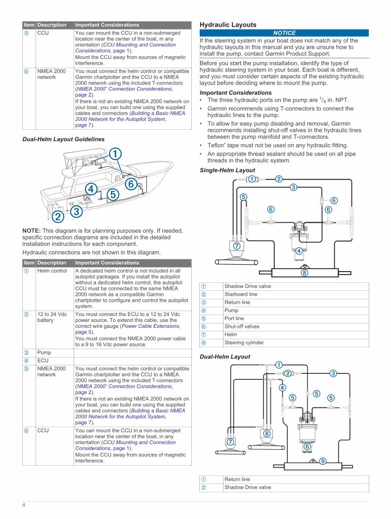
Hydraulic LayoutsNOTICE
If the steering system in your boat does not match any of the hydraulic layouts in this manual and you are unsure how to install the pump, contact Garmin Product Support.Before you start the pump installation, identify the type of hydraulic steering system in your boat. Each boat is different, and you must consider certain aspects of the existing hydraulic layout before deciding where to mount the pump.Important Considerations• The three hydraulic ports on the pump are 1/4 in. NPT.• Garmin recommends using T-connectors to connect the
hydraulic lines to the pump.• To allow for easy pump disabling and removal, Garmin
recommends installing shut-off valves in the hydraulic lines between the pump manifold and T-connectors.
• Teflon® tape must not be used on any hydraulic fitting.• An appropriate thread sealant should be used on all pipe
threads in the hydraulic system.Single-Helm Layout
À
Shadow Drive valveÁ
Starboard lineÂ
Return lineÃ
PumpÄ
Port lineÅ
Shut-off valvesÆ
HelmÇ
Steering cylinder
Dual-Helm Layout
À
Return lineÁ
Shadow Drive valve
4

Â
Starboard lineÃ
Port lineÄ
Shut-off valvesÅ
PumpÆ
Upper helmÇ
Lower helmÈ
Steering cylinder
Installation Procedures CAUTION
Always wear safety goggles, ear protection, and a dust mask when drilling, cutting, or sanding.
NOTICEWhen drilling or cutting, always check what is on the opposite side of the surface.After you have planned the autopilot installation on your boat and satisfied all of the mounting and wiring considerations for your particular installation, you can begin mounting and connecting the components.
Helm Control InstallationA dedicated helm control is not included in all autopilot packages. If you install the autopilot without a dedicated helm control, the autopilot CCU must be connected to the same NMEA 2000 network as a compatible Garmin chartplotter to configure and control the autopilot system.Detailed mounting instructions are included in the helm control box.
Mounting the CCU1 Determine the mounting location.2 Using the CCU as a template, mark the two pilot hole
locations on the mounting surface.3 Using a 3 mm (1/8 in.) bit, drill the pilot holes.4 Use the included screws to attach the CCU to the mounting
surface.NOTE: If you use mounting hardware other than the provided screws, the hardware must be quality stainless or brass material to avoid magnetic interference with the CCU.Test any mounting hardware with a handheld compass to make sure no magnetic fields are present in the hardware.
ECU InstallationMounting the ECUBefore you can mount the ECU, you must select a location and determine the correct mounting hardware (ECU Mounting and Connection Considerations, page 2).1 Hold the ECU in the intended mounting location and mark the
locations of the mounting holes on the mounting surface, using the ECU as a template.
2 Using a drill bit appropriate for the mounting surface and selected mounting hardware, drill the four holes through the mounting surface.
3 Secure the ECU to the mounting surface using the selected mounting hardware.
Connecting the ECU to Power WARNING
When connecting the power cable, do not remove the in-line fuse holder. To prevent the possibility of injury or product damage caused by fire or overheating, the appropriate fuse must be in place as indicated in the product specifications. In addition, connecting the power cable without the appropriate fuse in place voids the product warranty.
You should connect the ECU power cable directly to the boat battery, if possible. Although it is not recommended, if you connect the power cable to a terminal block or other source, you must connect it through a 40 A fuse.If you plan to route the ECU power through a breaker or a switch near the helm, you should consider using an appropriately sized relay and control wire instead of extending the ECU power cable.1 Route the connector-terminated end of the ECU power cable
to the ECU, but do not connect it to the ECU.2 Route the bare-wire end of the ECU power cable to the boat
battery.If the wire is not long enough, it can be extended (Power Cable Extensions, page 5).
3 Connect the black wire (-) to the negative (-) terminal of the battery, and connect the red wire (+) to the positive (+) terminal of the battery.
4 After you install all of the other autopilot components, connect the power cable to the ECU.
Power Cable ExtensionsIf necessary, you can extend the power cable using the appropriate wire gauge for the length of the extension.
Item DescriptionÀ
FuseÁ
BatteryÂ
9 ft. (2.7 m) no extension
Item DescriptionÀ
SpliceÁ
10 AWG (5.26 mm²) extension wireÂ
FuseÃ
8 in. (20.3 cm)Ä
BatteryÅ
8 in. (20.3 cm)Æ
Up to 15 ft. (4.6 m)
Item DescriptionÀ
SpliceÁ
8 AWG (8.36 mm²) extension wireÂ
FuseÃ
8 in. (20.3 cm)Ä
BatteryÅ
8 in. (20.3 cm)Æ
Up to 23 ft. (7 m)
5

Item DescriptionÀ
SpliceÁ
6 AWG (13.29 mm²) extension wireÂ
FuseÃ
8 in. (20.3 cm)Ä
BatteryÅ
8 in. (20.3 cm)Æ
Up to 36 ft. (11 m)
Pump InstallationMounting the PumpBefore you can mount the pump, you must select a location (Pump Mounting Considerations, page 2) and determine the correct mounting hardware (Tools Needed, page 1).1 Hold the pump in the intended mounting location and mark
the locations of the mounting holes on the mounting surface, using the pump as a template.
2 Using a drill bit appropriate for the mounting surface and selected mounting hardware, drill the four holes through the mounting surface.
3 Secure the pump to the mounting surface using the selected mounting hardware.
Connecting the Hydraulic Lines to the PumpFor assistance, see the layout diagrams (Hydraulic Layouts, page 4).1 Disconnect the necessary lines from the hydraulic system.2 Add a T-connector to the starboard and port lines of the
system between the helm and the steering cylinder.NOTE: If the boat has a power-assist module, you must add the T-connectors between the power-assist module and the steering cylinder.
3 Complete an action:• If the boat does not have a return line connected to the
helm, add enough hydraulic hose to connect the return fitting on the helm to the center pump fitting.
• If the boat has a return line connected to the helm, add a T-connector to the return line. If the return line is connected to a power-assist module, you must add the T-connector to the return line between the power-assist module and the helm.
4 Add hydraulic hose to the unused fitting on each T-connector, with enough hose to connect the T-connector to the pump fittings.
5 Connect the port and starboard line T-connectors to the appropriate pump fittings, as shown in the layout diagram for your hydraulic configuration.
6 Install the Shadow Drive valve in the port or starboard hydraulic line between the helm and the T-connector that connects to the pump (Installing the Shadow Drive Valve, page 6).
7 Install a shut-off valve (not included) on each hydraulic line that connects directly to the pump.
Connecting the CCURoute the orange and blue wires from the bare-wire portion of the CCU cable to the location where you plan to install the alarm (Installing the Alarm, page 6).
If the cable is not long enough, extend the appropriate wires with 0.08 mm2 (28 AWG) wire.
Installing the Shadow Drive ValveConnecting the Shadow Drive Valve to the Hydraulic SystemBefore you can install the Shadow Drive valve, you must select a location at which to connect the Shadow Drive to the hydraulic steering of your boat (Shadow Drive Mounting Considerations, page 2).For further assistance, consult the hydraulic-layout diagrams (Hydraulic Layouts, page 4).
Use hydraulic connectors (not included) to install the Shadow Drive valve in the appropriate hydraulic line.
Connecting the Shadow Drive Valve to the CCU1 Route the bare-wire end of the CCU cable to the Shadow
Drive valve.If the cable is not long enough, extend the appropriate wires with 28 AWG (0.08 mm²) wire.
2 Connect the cables, based on this table.Shadow Drive Valve Wire Color CCU Cable Wire ColorRed (+) Brown (+)Black (-) Black (-)
3 Solder and cover all bare-wire connections.
Installing an Autopilot SwitchIf your autopilot package does not include a Shadow Drive valve, you should install a manual Single Pole Single Throw (SPST) switch (not included) to disable the autopilot if necessary.1 Route the bare-wire end of the CCU cable to the switch.
If the cable is not long enough, extend the appropriate wires with 28 AWG (0.08 mm²) wire.
2 Connect the cables, based on this table.Switch Wire Function CCU Cable Wire ColorPositive (+) Brown (+)Negative (-) Black (-)
3 Solder and cover all bare-wire connections.The autopilot functions correctly when the switch contacts are closed. Opening the switch disables the autopilot for manual steering.
Installing the AlarmBefore you can mount the alarm, you must select a mounting location (Alarm Mounting and Connection Considerations, page 2).1 Route the alarm cable to the bare-wire end of the CCU cable.
If the cable is not long enough, extend the appropriate wires with 28 AWG (0.08 mm2) wire.
2 Connect the cables, based on this table.Alarm Wire Color CCU Cable Wire ColorWhite (+) Orange (+)Black (-) Blue (-)
3 Solder and cover all bare-wire connections.4 Secure the alarm with cable ties or other mounting hardware
(not included).
NMEA 2000 and the Autopilot ComponentsA dedicated helm control is not included in all autopilot packages. If you install the autopilot without a dedicated helm control, the autopilot CCU must be connected to the same NMEA 2000 network as a compatible Garmin chartplotter to configure and control the autopilot system.
6

NOTICEIf you are connecting this device to an existing NMEA 2000 network, the NMEA 2000 network should already be connected to power. Do not connect the NMEA 2000 power cable to an existing NMEA 2000 network, because only one power source should be connected to a NMEA 2000 network.If you are connecting this device to an existing NMEA 2000 network or engine network by another manufacturer, you should install a NMEA 2000 Power Isolator (010-11580-00) between the existing network and the Garmin devices.You can connect the CCU and the optional helm control through an existing NMEA 2000 network. If you do not have an existing NMEA 2000 network on your boat, all the parts needed to build one are supplied in the autopilot package (Building a Basic NMEA 2000 Network for the Autopilot System, page 7).To use the advanced features of the autopilot, optional NMEA 2000 devices, such as a GPS device, can be connected to the NMEA 2000 network.If you are unfamiliar with NMEA 2000, you should read the “NMEA 2000 Network Fundamentals” chapter of the Technical Reference for NMEA 2000 Products. To download this document, select Manuals on the product page for your device at www.garmin.com.Building a Basic NMEA 2000 Network for the Autopilot System
NOTICEIf you are installing a NMEA 2000 power cable, you must connect it to the boat ignition switch or through another in-line switch. NMEA 2000 devices will drain your battery if the NMEA 2000 power cable is connected to the battery directly.A dedicated helm control is not included in all autopilot packages. If you install the autopilot without a dedicated helm control, the autopilot CCU must be connected to the same NMEA 2000 network as a compatible Garmin chartplotter to configure and control the autopilot system.1 Connect the three T-connectors
À
together side-by-side.
2 Connect the included NMEA 2000 power cable Á
to a 9 to 12 Vdc power source
Â
through a switch Ã
.You should connect the power cable to the ignition switch of the boat if possible, or route it through an inline switch (not included).NOTE: The braided drain wire (bare) on the NMEA 2000 power cable must be connected to the same ground as the black wire on the NMEA 2000 power cable.
3 Connect the NMEA 2000 power cable to one of the T-connectors.
4 Connect one of the included NMEA 2000 drop cables Ä
to one of the T-connectors and to the helm control (optional) or to a compatible Garmin chartplotter
Å
.
5 Connect the other included NMEA 2000 drop cable to the other T-connector and to the CCU
Æ
.6 Connect the male and female terminators
Ç
to each end of the combined T-connectors.
Connecting the Autopilot Components to an Existing NMEA 2000 NetworkA dedicated helm control is not included in all autopilot packages. If you install the autopilot without a dedicated helm control, the autopilot CCU must be connected to the same NMEA 2000 network as a compatible Garmin chartplotter to configure and control the autopilot system.1 Determine where to connect the CCU
À
and the helm control (optional)
Á
to your existing NMEA 2000 backbone Â
.
2 In the location where you plan to connect the CCU, disconnect one side of a NMEA 2000 T-connector
Ã
from the network.
3 If necessary, connect a NMEA 2000 backbone extension cable (not included) to the side of the disconnected T-connector to extend the NMEA 2000 network backbone.
4 Add an included T‑connector for the CCU to the NMEA 2000 backbone by connecting it to the side of the disconnected T‑connector or backbone extension cable.
5 Route the included drop cable Ä
to the CCU and to the bottom of the T-connector added in step 4.If the included drop cable is not long enough, you can use a drop cable up to 6 m (20 ft.) long (not included).
6 Connect the drop cable to the CCU and the T-connector.7 If needed, repeat steps 2 through 6 for the helm control
(optional) or a compatible Garmin chartplotter.
Connecting Optional NMEA 2000 Devices to the Autopilot SystemYou can use advanced features of the autopilot system by connecting optional NMEA 2000 compatible devices, such as a GPS device, to the NMEA 2000 network.NOTE: You can connect optional devices that are not NMEA 2000 compatible to the helm control through NMEA 0183 (NMEA 0183 Connection Considerations, page 8).1 Add an additional T-connector (not included) to the NMEA
2000 network.2 Connect the optional NMEA 2000 device to the T-connector
by following the instructions provided with the device.
7

Bleeding the HydraulicsNOTICE
This is a general procedure for bleeding a hydraulic steering system. Refer to the instructions provided by the manufacturer of the steering system for more-specific information about bleeding the system.Before you bleed the hydraulic system, you should verify that all hose connections are complete and fully tightened.1 Select an option:
• If the helm reservoir contains insufficient fluid, fill it as needed.
• If the helm reservoir contains excess fluid, remove the excess to avoid fluid overflow during the bleeding process.
2 Insert a bypass hose between the cylinder bleed ports.TIP: If you use a clear plastic hose for this bypass, you can observe air bubbles during the bleeding processes.
3 Manually steer the helm fully to port.4 Open both bypass valves at the cylinder fittings.5 Manually turn the helm slowly to port over three minutes.
TIP: You can stop turning when you no longer see air moving through the bypass hose.
6 Turn on the autopilot system and disable the Shadow Drive.You can refer to the autopilot system documentation for more information on disabling the Shadow Drive.
7 Hold (port) on the helm control for at least 10 seconds.TIP: You can stop holding when you no longer see air moving through the bypass hose.
8 Close both bypass valves at the cylinder fittings.9 If necessary, add fluid to the helm reservoir.10Repeat steps 3 through 9 for the starboard side.11Hold (port) on the helm control until steering stops and
Hydraulic Pump Stall is shown on the helm control.12Hold (starboard) on the helm control until steering stops
and Hydraulic Pump Stall is shown on the helm control.13Select an option:
• If Hydraulic Pump Stall is not shown within 2 to 3 seconds after the cylinder stops, repeat steps 1-13 to bleed the system again.
• If Hydraulic Pump Stall is shown within 2 to 3 seconds after the cylinder stops, the system bleed completed successfully.
After hydraulic bleeding is complete, you can re-enable the Shadow Drive.
ConfigurationThe autopilot must be configured and tuned to your boat dynamics. You can use the Dockside Wizard and the Sea Trial Wizard on the helm control or a compatible Garmin chartplotter to configure the autopilot.See the included configuration guide for more information on configuring the autopilot.
AppendixNMEA 0183 Connection DiagramsThe helm control is not included in all autopilot packages. A helm control must be installed in your autopilot system to connect NMEA 0183 devices according to these diagrams. If you install the autopilot without a helm control, all NMEA devices you plan to use with the autopilot system must be connected to a compatible Garmin chartplotter on the same NMEA 2000 network as the CCU. See the installation instructions provided with your chartplotter for NMEA 0183 connection information.
These wiring diagrams are examples of different situations you may encounter when connecting your NMEA 0183 device to the helm control.NMEA 0183 Connection Considerations• There is one internal NMEA 0183 input port (RX port) and
one internal NMEA 0183 output port (TX port) on the included NMEA 0183 data cable. You can connect one NMEA 0183 device to the internal RX port to input data to this Garmin device, and you can connect up to three NMEA 0183 devices in parallel to the internal TX port to receive data output by this Garmin device.
• See the installation instructions for the NMEA 0183 device to identify the transmit (TX) and receive (RX) wires.
• The device provides one TX port and one RX port. Each internal port has 2 wires, labeled A and B according to the NMEA 0183 convention. The corresponding A and B wires of each internal port should be connected to the A (+) and B (-) wires of the NMEA 0183 device.
• You must use 28 AWG, shielded, twisted-pair wiring for extended runs of wire. Solder all connections and seal them with heat-shrink tubing.
• Do not connect the NMEA 0183 data wires from this device to power ground.
• The power cable from this device and the NMEA 0183 devices must be connected to a common power ground.
• See Specifications, page 9 for a list of the approved NMEA 0183 sentences that are output by and input to this device.
• The internal NMEA 0183 ports and communication protocols are configured on the connected Garmin device. See the NMEA 0183 section of the chartplotter owner's manual for more information.
Two-Way NMEA 0183 Communication
À
NMEA 2000 network (provides power to the helm control)Á
12 Vdc power sourceÂ
Helm controlÃ
NMEA 0183 compatible device
Wire Helm Control Wire Color — Function
NMEA 0183 Compatible Device Wire Function
Ê
N/A PowerË
N/A NMEA 0183 groundÌ
Blue — Tx/A (+) Rx/A (+)Í
White — Tx/B (-) Rx/B (-)Î
Brown — Rx/A (+) Tx/A (+)Ï
Green — Rx/B (-) Tx/B (-)
NOTE: When connecting a NMEA 0183 device with two transmitting and two receiving lines, you do not need to connect the NMEA 2000 bus and the NMEA 0183 device to a common ground.
8

Only One Receiving WireIf your NMEA 0183 compatible device has only one receiving wire (Rx), you must connect it to the blue wire (Tx/A) from the helm control, and leave the white wire (Tx/B) from the helm control unconnected.
À
NMEA 2000 network (provides power to the helm control)Á
12 Vdc power sourceÂ
Helm controlÃ
NMEA 0183 compatible device
Wire Helm Control Wire Color — Function
NMEA 0183 Compatible Device Wire Function
Ê
N/A PowerË
N/A NMEA 0183 groundÌ
Blue — Tx/A (+) RxÍ
White — unconnected N/AÎ
Brown — Rx/A (+) Tx/A (+)Ï
Green — Rx/B (-) Tx/B (-)
NOTE: When connecting a NMEA 0183 device with only one receiving (Rx) line, you must connect the NMEA 2000 bus and the NMEA 0183 device to a common ground.Only One Transmitting WireIf your NMEA 0183 compatible device has only one transmitting wire (Tx), it must be connected to the brown wire (Rx/A) from the helm control, and the green wire (Rx/B) from the helm control must be connected to NMEA 0183 ground.
À
NMEA 2000 network (provides power to the helm control)Á
12 Vdc power sourceÂ
Helm controlÃ
NMEA 0183-compatible device
Wire Helm Control Wire Color — Function
NMEA 0183 Compatible Device Wire Function
Ê
N/A PowerË
Green — Rx/B (-) (connect to NMEA 0183 ground)
NMEA 0183 ground
Wire Helm Control Wire Color — Function
NMEA 0183 Compatible Device Wire Function
Ì
Blue — Tx/A (+) Rx/A (+)Í
White — Tx/B (-) Rx/B (-)Î
Brown — Rx/A (+) Tx/A (+)
NOTE: When connecting a NMEA 0183 device with only one transmitting (Tx) line, you must connect the NMEA 2000 bus and the NMEA 0183 device to a common ground.
SpecificationsCompact PumpSpecification MeasurementDimensions (H × W × D) 84.6 x 100.3 x 155.3 mm (3.3 × 4.0 ×
6.1 in.)Weight 2.2 kg (5 lb.)Temperature range From -15° to 75°C (from 5° to 167°F )Material • Motor frame: Powder coat gloss black
• Motor end caps: Cast aluminum ADC12• Pump body and cap: Anodized die cast
ADC12• Mounting bracket: 304 stainless steel
ECU cable length 0.6 m (24 in.)Input voltage (from the ECU)
13.8 Vdc max.
Main power usage (from the ECU)
• Standby: Less than 1 A• Engaged: From 5 to 10 A• Peak: 34 A
CCUSpecification MeasurementDimensions (L × W × H) 170 × 90 × 50 mm (6.7 × 3.5 × 2 in.)Weight 200 g (7 oz.)Temperature range From -15° to 70°C (from 5° to 158°F)Material Fully gasketed, high-impact plasticWater resistance IEC 60529 IPX7*NMEA 2000 input voltage From 9 to 16 VdcNMEA 2000 LEN 4 (200 mA)*The device withstands incidental exposure to water of up to 1 m for up to 30 min. For more information, go to www.garmin.com/waterrating.
ECUSpecification MeasurementDimensions (W × H × D) 168 × 117 × 51 mm (6.6 × 4.6 × 2 in.)Weight 680 g (24 oz.)Temperature range From -15° to 60°C (from 5° to 140°F)Material Fully gasketed, high-impact aluminum
alloyWater resistance IEC 60529 IPX7*Power cable length 2.7 m (9 ft.)Input voltage From 11.5 to 30 VdcFuse 40 A, blade-typeMain power usage 1 A (not including the pump)*The device withstands incidental exposure to water of up to 1 m for up to 30 min. For more information, go to www.garmin.com/waterrating.
AlarmSpecification MeasurementDimensions (L×diameter) 29/32 × 1 in. (23 × 25 mm)Weight 2.4 oz. (68 g)Temperature range From 5°F to 140°F (from -15°C to 60°C)Cable length 10 ft. (3.0 m)
9

NMEA 2000 PGN InformationCCUType PGN DescriptionTransmit and receive
059392 ISO acknowledgment
059904 ISO request060928 ISO address claim126208 NMEA: Command/Request/Acknowledge
group function126464 Transmit/Receive PGN list group function126996 Product information127257 Transmit/Receive attitude data127251 Transmit/Receive rate of turn
Transmit only 127250 Vessel headingReceive only 127258 Magnetic variation
127488 Engine parameters: Rapid update128259 Water speed129025 Position: Rapid update129026 COG & SOG: Rapid update129283 Cross track error129284 Navigation data130306 Wind data
Helm ControlType PGN DescriptionTransmit and receive
059392 ISO acknowledgment
059904 ISO request060928 ISO address claim126208 NMEA: Command/Request/Acknowledge
group function126464 Transmit/Receive PGN list group function126996 Product information
Transmit only 128259 Water speed129025 Position: Rapid update129026 COG & SOG: Rapid update129283 Cross track error129284 Navigation data129540 GNSS satellites in view130306 Wind data
Receive only 127245 Rudder data127250 Vessel heading127488 Engine parameters: Rapid update128259 Water speed129025 Position: Rapid update129029 GNSS position data129283 Cross-track error129284 Navigation data129285 Navigation: Route/Waypoint information130306 Wind data130576 Small craft status
NMEA 0183 InformationWhen connected to optional NMEA 0183 compatible devices, the autopilot uses the following NMEA 0183 sentences.Type SentenceTransmit hdmReceive wpl
gga
Type Sentencegrmegsagsvrmcbodbwcdtmgllrmbvhwmwvxte
Error and Warning MessagesError Message Cause Autopilot ActionECU Voltage is Low The pump supply voltage
has fallen below 10 Vdc for longer than 6 seconds.
• Alarm sounds for 5 seconds
• Continues in normal operation
Autopilot is not receiving navigation data. Autopilot placed in Heading Hold.
The autopilot is no longer receiving valid navigation data while performing a Route To maneuver.This message also appears if navigation is stopped on a chartplotter before the autopilot is disengaged.
• Alarm sounds for 5 seconds
• Autopilot transitions to heading hold
Connection with Autopilot Lost
The helm control has lost connection with the CCU.
N/A
Lost Wind Data (sailboat only)
The autopilot is no longer receiving valid wind data.
• Alarm sounds for 5 seconds
• Autopilot transitions to heading hold
Low GHC™ Supply Voltage
The supply voltage level has fallen below the value specified in the low voltage alarm menu.
N/A
Error: ECU High Voltage
The pump supply voltage has risen above 33.5 Vdc.
• Alarm sounds for 5 seconds
• The ECU shuts down
Error: ECU Voltage has Dropped Rapidly
The ECU voltage has dropped quickly below 7.0 Vdc.
• Alarm sounds for 5 seconds
• The error is cleared when the ECU voltage rises above 7.3 Vdc.
Error: ECU High Temperature
The ECU temperature has risen above 100°C (212°F ).
• Alarm sounds for 5 seconds
• The ECU shuts down
Error: Lost Communication Between ECU and CCU (when the autopilot is engaged)
Communication between the CCU and the ECU has timed out.
• The helm control beeps, and autopilot transitions to standby.
Registering Your DeviceHelp us better support you by completing our online registration today. Keep the original sales receipt, or a photocopy, in a safe place.1 Go to garmin.com/express .2 Sign in to your Garmin account.
10

Contacting Garmin Support• Go to support.garmin.com for help and information, such as
product manuals, frequently asked questions, videos, and customer support.
• In the USA, call 913-397-8200 or 1-800-800-1020.• In the UK, call 0808 238 0000.• In Europe, call +44 (0) 870 850 1241.
© 2017 Garmin Ltd. or its subsidiariesGarmin® and the Garmin logo are trademarks of Garmin Ltd. or its subsidiaries, registered in the USA and other countries. Reactor™ and Shadow Drive™ are trademarks of Garmin Ltd. or its subsidiaries. These trademarks may not be used without the express permission of Garmin.NMEA®, NMEA 2000®, and the NMEA 2000 logo are trademarks of the National Marine Electronics Association.
11