Reactive Power Control of Direct Drive Synchronous Generators to
14
21 Reactive Power Control of Direct Drive Synchronous Generators to Enhance the Low Voltage Ride-Through Capability Andrey C. Lopes, André C. Nascimento, João P. A. Vieira, Marcus V. A. Nunes and Ubiratan H. Bezerra Federal University of Pará Brazil 1. Introduction The development of wind power generation has grown considerably during the last years. The use of wind generators forming groups denominated wind farms, operating together with conventional sources of energy in weak grids has also increased [1]. The increased penetration of wind energy into the power system over the last few years is directly reflected in the requirements for grid connection of wind turbines. These codes are becoming more and more demanding, requiring wind farms to behave more and more as conventional power plants in the power system. Therefore it is essential to analyze the characteristics of wind generators during the network disturbances [2]. Currently, most of the grid requirements address low voltage ride-through (LVRT) and grid support capabilities of the wind generators. The LVRT requirement specifies that wind generators need to remain connected to the grid when an abnormal grid voltage is detected (e.g. during short-circuit faults). The grid support capability specifies wind generators to assist the power system by supplying ancillary services, such as voltage control, to assure a safe and reliable grid operation. Power electronics based solutions for grid interfacing of wind turbines seem to be a very promising technology that can cope with these grid requirements. The configurations of variable speed wind generation that employ direct drive synchronous generators with permanent magnet and rotor field excitation, present noticeable advantages such as the decoupled control of the generators active and reactive power, the improvement of system efficiency and the fact that the machine stator frequency is decoupled from the grid frequency. The stator converter uses a high frequency switching PWM converter to achieve high control performance with low harmonic distortion, [3]. Due to those aspects in a worldwide basis and specifically in Brazil, there is a trend to install a large amount of wind power based on that technology. The interaction with the grid becomes increasingly important then. This can be understood as follows. When all wind generators would be disconnected in case of a grid failure, these renewable generators will—unlike conventional power plants—not be able to support the voltage and the grid frequency during and immediately following the grid failure. This would cause major problems for the system stability [3]. www.intechopen.com
Transcript of Reactive Power Control of Direct Drive Synchronous Generators to

21
Reactive Power Control of Direct Drive Synchronous Generators to Enhance the
Low Voltage Ride-Through Capability
Andrey C. Lopes, André C. Nascimento, João P. A. Vieira, Marcus V. A. Nunes and Ubiratan H. Bezerra
Federal University of Pará Brazil
1. Introduction
The development of wind power generation has grown considerably during the last years.
The use of wind generators forming groups denominated wind farms, operating together
with conventional sources of energy in weak grids has also increased [1]. The increased
penetration of wind energy into the power system over the last few years is directly
reflected in the requirements for grid connection of wind turbines. These codes are
becoming more and more demanding, requiring wind farms to behave more and more as
conventional power plants in the power system. Therefore it is essential to analyze the
characteristics of wind generators during the network disturbances [2].
Currently, most of the grid requirements address low voltage ride-through (LVRT) and grid
support capabilities of the wind generators. The LVRT requirement specifies that wind
generators need to remain connected to the grid when an abnormal grid voltage is detected
(e.g. during short-circuit faults). The grid support capability specifies wind generators to assist
the power system by supplying ancillary services, such as voltage control, to assure a safe and
reliable grid operation. Power electronics based solutions for grid interfacing of wind turbines
seem to be a very promising technology that can cope with these grid requirements.
The configurations of variable speed wind generation that employ direct drive synchronous generators with permanent magnet and rotor field excitation, present noticeable advantages such as the decoupled control of the generators active and reactive power, the improvement of system efficiency and the fact that the machine stator frequency is decoupled from the grid frequency. The stator converter uses a high frequency switching PWM converter to achieve high control performance with low harmonic distortion, [3]. Due to those aspects in a worldwide basis and specifically in Brazil, there is a trend to install
a large amount of wind power based on that technology. The interaction with the grid
becomes increasingly important then. This can be understood as follows. When all wind
generators would be disconnected in case of a grid failure, these renewable generators
will—unlike conventional power plants—not be able to support the voltage and the grid
frequency during and immediately following the grid failure. This would cause major
problems for the system stability [3].
www.intechopen.com

Wind Turbines
496
With the perspective of integration of more wind parks in Brazil the Grid National Operator
(ONS) already has set requirements for the behavior of the wind generators protection.
Instead of disconnecting them from the grid, the wind generators should be able to follow
the characteristic shown in Fig. 1.
Only when the grid voltage goes below the curve (in duration or voltage level), the wind generators is allowed to disconnect. When the voltage is in the gray area, the wind generators should supply reactive power. In this paper a method is proposed that makes it possible for wind generators using direct drive synchronous generators to stay connected to the grid during faults.
Fig. 1. ONS Requirements for Wind Parks Behaviour during Faults.
The main attention of the chapter is focused on the control strategies of the grid-side converter to provide reactive power support in case of grid disturbances. This control strategy can improve the voltage level during the fault and also contribute to the LVRT requirement. For strong grids there is a decoupling between the active and reactive powers. Thus the total
reactive power injection during a fault is a good solution for this control strategy without to
compromissing the power system transient stability. However if the wind farm is connected
to a weak electrical grid (i.e. voltage and frequency fluctuations conditions), there may be
some power surge problems due to technical constraints related to the weak grid. In this
case the proposed control strategy is based in the reactive injection curve defined by the grid
code requirement improving the power system transient stability.
In this chapter, a variable speed wind turbine with a power electronic interface (a full power
converter system) is considered. It is assumed that the wind turbines are equipped with a
voltage dip ride-through facility and have a rapid current controller. Based on these
assumptions, the wind park is modeled as a current injection source with current limitation
determined by the converter capacity constraint. A similar approach of modeling a wind
park was also adopted in [4] and [5]. The reference current is generated in accordance with
the E.ON grid code which is then injected into the grid.
www.intechopen.com

Reactive Power Control of Direct Drive Synchronous Generators to Enhance the Low Voltage Ride-Through Capability
497
2. Grid requirements and fault ride-through capability
For this study, a set of minimum technical requirements concerning the installation of new wind farm was defined. The interconnection requirements, active and reactive power control and fault ride-through capability are based on the E.ON grid codes and ONS requirements. The Wind Farm covered by the ONS requirements should present Fault Ride Through Capability in order to stay connected to the grid if during and in the moments subsequent to a fault or system disturbance the wind farm terminal voltage is above the value defined in the Time-Voltage characteristic curve presented in Fig. 1. Below the line, the wind park is allowed to trip. For OEN grid code, it is required that during voltage dips a demand of reactive power injection must follow a specified curve. This requirement, besides improving the voltage levels in the electric grid in a defect condition, allows the wind park not to be removed of the system by the trip of the under voltage relay, increasing the ride-through capacity. The generating plants must support the grid voltage with additional reactive current during
a voltage dip. To do this, the voltage control must be activated as shown in Fig. 2 in the
event of a voltage dip of more than 10% of the rms generator voltage. The voltage control
must take place within 20 ms after fault recognition by providing a reactive current on the
voltage side of the generator transformer amounting to at least 2% of the rated current for
each percent of the voltage dip. A reactive power output of at least 100% of the rated current
must be possible if necessary [EON]. The reactive injection curve is generated in accordance
with the E.ON grid code as shown in Fig 2.
Fig. 2. The Principle of Voltage Support in Event of Grid Faults
When the voltage dip goes larger than 10% of the rated generator voltage the control action should act 20 ms after the identification of the fault, supplying reactive current on the low voltage side of the generator transformer at least 2% of the nominal current for each 1% of voltage dip.
www.intechopen.com

Wind Turbines
498
3. Direct drive PMSG wind generators and controls
3.1 Modeling assumptions
The first stage in the simulation process is to model individual system components with an
appropriate degree of complexity. The structure of the direct drive PMSG wind power
system is shown in Fig. 3, in which the generator-side converter is a diode rectifier, the grid-
side converter is a Pulse Width Modulation (PWM) inverter used to sustain the dc-bus
voltage and regulate the grid-side power factor controlled independently through the
decoupled d-q vector control approach for modern PMSG wind generators designs. The DC-
link created by the capacitor in the middle decouples the operation of the two converters, as
shown in Fig. 3.
Fig. 3. Configuration of a PMSG Wind Generators
It has been demonstrated that the PMSG speed changes during voltage dips are negligible
[6]. This is because the power supply to the DC circuit from the machine-side converter is
approximately constant. So in terms of the grid connecting point (PCC) results, the PMSG
mechanical behavior is not particularly relevant. So the model of the PMSG and the
machine-side converter, can be omitted. A constant DC power current source can be used to
represent these instead (thus neglecting the machine side power fluctuations), and the
simulation results at the PCC will not be greatly compromised [6].
3.2 Simplified model
The model introduced in this section is a simplification of the model used in the previous
section. In this model, the DC link voltage is controlled with a boost-chopper. The grid-side
inverter is controlling the reactive power as usual. Fig. 4 shows the structure of this
simplified model with the modified grid-side inverter controller.
Fig. 4. Structure of the Simplified Model
In Fig. 4, P0 represents the initial active power at the beginning of the simulation, based on
the assumption of constant wind speed (wind power) in the wind farm during the short
simulation time frame.
www.intechopen.com

Reactive Power Control of Direct Drive Synchronous Generators to Enhance the Low Voltage Ride-Through Capability
499
4. Models of the converters
Wind generators based on synchronous machines are connected to the electrical grid through static converters as illustrated previously in Fig. 3. In these cases it is required to model both converters, that is, the converter connected to the electrical grid and the one connected to the generator stator, which are both self-commutated PWM converters.
4.1 The grid-side converters models
The grid side converter as showed in Fig. 5 is controlled using a synchronous reference frame. The active part of the complex current becomes Iq and the reactive part is Id. The ouput power of the converter may be written as:
( )s s q q dS P jQ V I jI= + = − (1)
The converter terminal voltage, V´, is defined as:
3
2 2DCV mV′ = (2)
The pulse-width modulation index m is the control variable of the PWM converter. Equation (2) is valid for 0 ≤ m < 1. Reactive power is controlled directly by the reactive current Iq. If the converter is to operate with unity power factor, the reference for the reactive current must be set equal to zero. The output signals in the converter model are the pulse modulation.
Fig. 5. Grid-Side Converter Schematic
Fig. 6. Control Loop for the Grid-Side Converter
www.intechopen.com

Wind Turbines
500
Fig. 7. Control Loop for the DC-Link Voltage
5. The sample power system
The electrical network used as a basis for this investigation is similar to that in [7]. For this
system, a wind park is planned to be installed at bus 2 as illustrated in Fig. 8. The wind
park to be connected is considered in this study as a dynamic equivalent, this way, an
equivalent wind generator of 16MW and 400 V is considered. Each machine has a rated
capacity of 2 MW and is designed to operate with rated terminal voltage of 400 V. The
wind park is to be connected to the distribution electrical grid by 0.4/13.8 kV
transformers. Besides the wind farm generation, two conventional diesel electric plants of
75 MVA and 36 MVA respectively connected to buses 1 and 3 are rated to supply the
electric load of this system.
The model parameters of the speed and voltage regulators and synchronous generators of
the diesel units were obtained from [9] and [10]. The equivalent automatic voltage regulator
used is an IEEE Type 1 model. The equivalent primary machine of the synchronous
generator and its speed governor are first-order models with proportional/integral
frequency control [11], [12].
Fig. 8. Electrical Grid with Wind and Diesel Generation
www.intechopen.com
Reactive Power Control of Direct Drive Synchronous Generators to Enhance the Low Voltage Ride-Through Capability
501
6. Results
The simulation studies were performed considering a new operational practice that
recommends to keep the wind generators in operation even during the fault period. The
evaluation of reactive power injection during the fault will be performed on two conditions:
the first is the adopted by Brazilian grid code which does not require the reactive power
injection. The second injects reactive power following the EON curve.
6.1 Case I
The wind park generation at bus 2 was simulated using the full capacity of the park at 2
MW rated power on each synchronous generator. The short circuit was located near bus 1,
starting at t = 1s, and lasting for 500 ms.
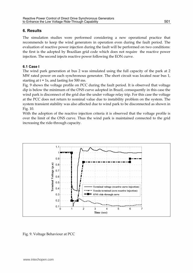
Fig. 9 shows the voltage profile on PCC during the fault period. It is observed that voltage
dip is below the minimum of the ONS curve adopted in Brazil, consequently in this case the
wind park is disconnect of the grid due the under voltage relay trip. For this case the voltage
at the PCC does not return to nominal value due to instability problem on the system. The
system transient stability was also affected due to wind park to be disconnected as shown in
Fig. 10.
With the adoption of the reactive injection criteria it is observed that the voltage profile is
over the limit of the ONS curve. Thus the wind park is maintained connected to the grid
increasing the ride-through capacity.
0 1 2 3 4 5 6 70.1
0.2
0.3
0.4
0.5
0.6
0.7
0.8
0.9
1
1.1
Time (sec)
Ter
min
al
Vo
lta
ge
(p.u
)
Terminal voltage (reactive curve injection)
Tensão terminal (zero reactive injection)
ONS ride-through curve
Fig. 9. Voltage Behaviour at PCC
www.intechopen.com

Wind Turbines
502
0 1 2 3 4 5 6 7-2
-1.5
-1
-0.5
0
0.5
time (sec)
roto
r a
ng
le (
rad
)
with reactive injection curve)
with zero reative injection)
Fig. 10. Rotor Angle of the Synchronous Generator at bus 1.
0 2 4 6 8 10 12-0.02
0
0.02
0.04
0.06
0.08
0.1
0.12
0.14
0.16
gri
d s
ide
act
ive
an
d r
eact
ive
po
wer
(p
.u)
Time (sec)
Qt (reactive injection curve)
Pt (reactive injection curve)
Fig. 11. Reactive and Active Power at PCC
6.2 Case II
The wind park generation at bus 6 was simulated using the full capacity of the wind park at
2 MW rated power on each synchronous generator. The short circuit was located near bus 6,
starting at t = 1s, and lasting for 200 ms. Fig. 12 shows the voltage profile on PCC during the
fault period. It is observed that the voltage dip is 0.65 p.u for the case of zero reactive
injection, whereas for the case of following the reactive power injection curve the voltage
dip is 0.8 p.u. and the reactive current support is provided within 20 ms after the fault
detection in accordance with the E.ON regulation requirement. Thus the reactive power
injection curve improves voltage profile and the ride-through capability.
www.intechopen.com

Reactive Power Control of Direct Drive Synchronous Generators to Enhance the Low Voltage Ride-Through Capability
503
0 1 2 3 4 5 6 7
0.65
0.7
0.75
0.8
0.85
0.9
0.95
1
1.05
Time (sec)
Ter
min
al
volt
ag
e (p
.u.)
With zero reactive injection
With reactive injection curve
Fig. 12. Voltage Behaviour at PCC
Fig. 13 shows the converter reactive power which follows the reactive injection curve during the fault, improving the voltage profile as shown in Fig. 12. The E.ON grid code requirements allow the active power injection by the converter when the voltage dip is above 0.5 p.u. as shown in Fig. 14. It is also observed after fault cleaning time a power injection ramp until the reference power. This method increases the transient stability margin as shown in Fig. 15, in which it is observed a small rotor angle oscillation with the reactive power injection curve.
0 1 2 3 4 5 6 7-0.02
-0.01
0
0.01
0.02
0.03
0.04
0.05
0.06
Timpe (sec)
Gri
de
Sid
e re
act
ive
po
wer
(p
.u.)
With zero reactive injection
With reactive injection curve
Fig. 13. Reactive Power at PCC
www.intechopen.com

Wind Turbines
504
0 1 2 3 4 5 6 7-0.02
0
0.02
0.04
0.06
0.08
0.1
0.12
0.14
0.16
0.18
Timpe (sec)
Gri
d s
ide
act
ive
pow
er (
p.u
.)
With zero reactive injection
With reactive invection curve
Fig. 14. Active Power at PCC
0 1 2 3 4 5 6 7-36
-34
-32
-30
-28
-26
-24
-22
-20
-18
-16
Time (sec)
roto
r an
gle
(d
eg)
With zero reactive injection
With reactive injection curve
Fig. 15. Rotor Angle of the Synchronous Generator at Bus 1
www.intechopen.com

Reactive Power Control of Direct Drive Synchronous Generators to Enhance the Low Voltage Ride-Through Capability
505
7. Conclusion
In this chapter, it was explored the performance of alternative voltage control strategies
applied to direct drive synchronous wind generators, more specifically with permanent
magnetic (PMSG). The reactive power control of the grid-side converter is investigated for
voltages purposes. The E.ON fault response code for wind farms is taken as the base case
for the study. The simulated results presented in this chapter have considered that the
proposed operational procedure has kept running during the fault period (ride-through
capability) the wind generators, and also offers the possibility to supply reactive power
during the voltage dip in order to facilitate voltage restoration. This is possible with the
control of the grid side converter. The results have demonstrated that the consequence of
this new approach is positive in the sense of maintaining transient voltage and rotor angle
stability, once a variable speed wind generator technology, as direct drive synchronous
generator is used.
8. References
[1] A.D. Hansen, G. Michalke, “Multi-pole permanent magnet synchronous generator wind
turbines,” grid support capability in uninterrupted operation during grid faults.
IET Renew. Power Gener., 2009, Vol. 3, Iss. 3, pp. 333–348.
[2] A.D. Hansen, L.H. Hansen, “Wind turbine concepts market penetration over ten years
(1995 to 2004)’, Wind Energy, 2007, 10, (1), pp. 81–97
[3] J. P. A. Vieira, M. V. A. Nunes, A. C. Nascimento, S. R. Silva, U. H. Bezerra, M. F.
Medeiros Júnior, “Analysis of Ride-Through With the Integration of Direct Drive
Synchronous Wind Generators in Power Systems” In: VII INDUSCON, 2006,
Recife. 2006. v1. p1-6.
[4] N. R. Ullah, T. Thiringer, “Variable speed wind turbines for power system stability
enhancement” IEEE Trans. Energy Conv., vol. 22, no. 1, pp. 52-60, mar. 2007.
[5] A. Larson, A. Petersson, N. R. Ullah, O. Carlsson, “Krieger’s flak wind farm” in Proc.
Nordic Wind Power Conf. NWPC 2006, Helsinki, Finland, May 2006.
[6] J. Conroy, R. Watson, “Aggregate modelling of wind farms containing full-converter
wind turbine generators with permanent magnet synchronous machines: transient
stability studies” IET Renewable Power Generation. 2009, vol 3, N. 1, pp. 39-52.
[7] M. V. A. Nunes, J. A. Peças Lopes, H. H. Zurn, U. H. Bezerra, R. G. Almeida, “Influence
of the Variable-Speed Wind Generators in Transient Stability Margin of The
Conventional Generators Integrated in Electrical Grids” IEEE Transactions on
Energy Conversion, Vol. 19, NO. 4, December 2004.
[8] Grid Code: High and Extra High Voltage, E. ON Netz GmbH Tech. Rep., 2006, Status: 1.
[9] P. Kundur, Power system stability and contol, Electric Power Research Institue McGrall-
Hill, 1994.
[10] P. M. Anderson, A. A. Fouad, “Analysis of Faulted Power Systems” Ames, Iowa: Iowa
State Univ. Press, 1995.
[11] G. N. Kariniotakis, G. S. Stavrakakis, “A general simulation for the accurate assessment
of isolated diesel-wind turbines interaction, part I: a general multimachine power
system model,” IEEE Trans. Energy Conversion, vol. 10, pp. 577–583, Sept. 1995.
www.intechopen.com

Wind Turbines
506
[12] N. Jenkins, J.B. Ekanayake, L. Holsworth, X. Wu, “Dynamic modeling of doubly fed
induction generator wind turbines,” IEEE Trans. Power Syst., vol. 18, pp. 803–809,
May 2003.
www.intechopen.com

Wind TurbinesEdited by Dr. Ibrahim Al-Bahadly
ISBN 978-953-307-221-0Hard cover, 652 pagesPublisher InTechPublished online 04, April, 2011Published in print edition April, 2011
InTech EuropeUniversity Campus STeP Ri Slavka Krautzeka 83/A 51000 Rijeka, Croatia Phone: +385 (51) 770 447 Fax: +385 (51) 686 166www.intechopen.com
InTech ChinaUnit 405, Office Block, Hotel Equatorial Shanghai No.65, Yan An Road (West), Shanghai, 200040, China
Phone: +86-21-62489820 Fax: +86-21-62489821
The area of wind energy is a rapidly evolving field and an intensive research and development has taken placein the last few years. Therefore, this book aims to provide an up-to-date comprehensive overview of thecurrent status in the field to the research community. The research works presented in this book are dividedinto three main groups. The first group deals with the different types and design of the wind mills aiming forefficient, reliable and cost effective solutions. The second group deals with works tackling the use of differenttypes of generators for wind energy. The third group is focusing on improvement in the area of control. Eachchapter of the book offers detailed information on the related area of its research with the main objectives ofthe works carried out as well as providing a comprehensive list of references which should provide a richplatform of research to the field.
How to referenceIn order to correctly reference this scholarly work, feel free to copy and paste the following:
Andrey C. Lopes, André C. Nascimento, João P. A. Vieira, Marcus V. A. Nunes and Ubiratan H. Bezerra(2011). Reactive Power Control of Direct Drive Synchronous Generators to Enhance the Low Voltage Ride-Through Capability, Wind Turbines, Dr. Ibrahim Al-Bahadly (Ed.), ISBN: 978-953-307-221-0, InTech, Availablefrom: http://www.intechopen.com/books/wind-turbines/reactive-power-control-of-direct-drive-synchronous-generators-to-enhance-the-low-voltage-ride-throug

© 2011 The Author(s). Licensee IntechOpen. This chapter is distributedunder the terms of the Creative Commons Attribution-NonCommercial-ShareAlike-3.0 License, which permits use, distribution and reproduction fornon-commercial purposes, provided the original is properly cited andderivative works building on this content are distributed under the samelicense.