Reaction Control system Design Considerations for … · Reaction Control system Design...
20
Mars Science Laboratory Reaction Control system Design Considerations for Mars Entry Vehicles Artem Dyakonov April, 2007 PRE-DECISIONAL DRAFT; For planning and discussion purposes only 1 3/12/2008 https://ntrs.nasa.gov/search.jsp?R=20080013457 2018-06-24T12:00:56+00:00Z
Transcript of Reaction Control system Design Considerations for … · Reaction Control system Design...
Mars Science Laboratoryy
Reaction Control system Design Considerations for Mars Entry Vehicles
Artem Dyakonov
April, 2007
PRE-DECISIONAL DRAFT; For planning and discussion purposes only 13/12/2008
https://ntrs.nasa.gov/search.jsp?R=20080013457 2018-06-24T12:00:56+00:00Z
AAD
TeamAAD
Chris E. Glass, NASA LaRC Mark Schoenenberger, NASA LaRC
William I. Scallion, NASA LaRCArtem A. Dyakonov, NASA LaRC
Brian R. Hollis, NASA LaRCKarl T. Edquist, NASA LaRC
Pawel Chwalowski, AMAJohn Van-Norman, AMA
Victor R. Lessard, GENEXNaru Takashima, APL
Michael J. Wright, NASA AmesgChun Tang, NASA Ames
23/12/2008 2
AAD
OverviewAAD
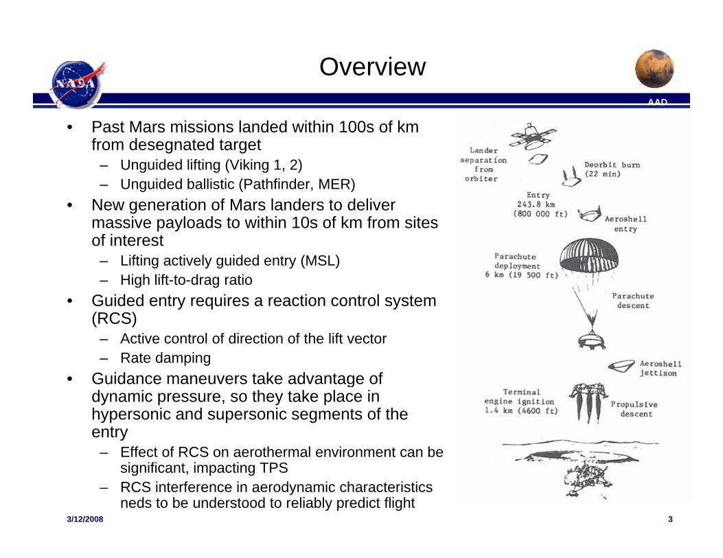
• Past Mars missions landed within 100s of km from desegnated target
– Unguided lifting (Viking 1, 2) – Unguided ballistic (Pathfinder, MER)
• New generation of Mars landers to deliver massive payloads to within 10s of km from sites of interestof interest
– Lifting actively guided entry (MSL)– High lift-to-drag ratio
• Guided entry requires a reaction control system (RCS)(RCS)
– Active control of direction of the lift vector– Rate damping
• Guidance maneuvers take advantage of gdynamic pressure, so they take place in hypersonic and supersonic segments of the entry
– Effect of RCS on aerothermal environment can be
33/12/2008 3
Effect of RCS on aerothermal environment can be significant, impacting TPS
– RCS interference in aerodynamic characteristics neds to be understood to reliably predict flight
AAD
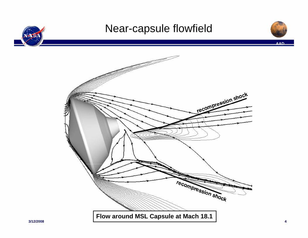
Near-capsule flowfieldAAD
43/12/2008 4
Flow around MSL Capsule at Mach 18.1
AAD
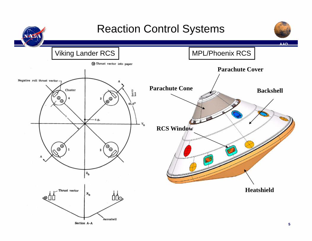
Reaction Control SystemsAAD
Viking Lander RCS
Parachute Cover
MPL/Phoenix RCS
BackshellParachute Cone
RCS Window
Heatshield
53/12/2008 5
AAD
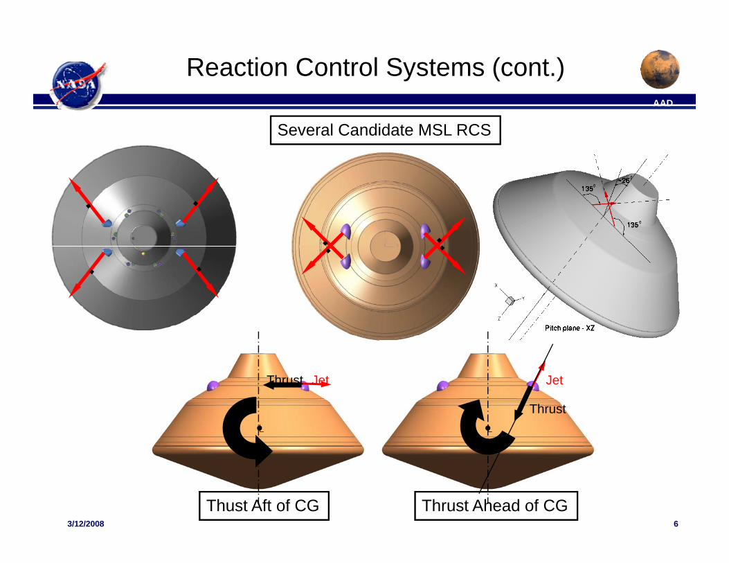
Reaction Control Systems (cont.)AAD
Several Candidate MSL RCS
JetThrust Jet
� �
Thrust
63/12/2008 6
Thust Aft of CG Thrust Ahead of CG
AAD
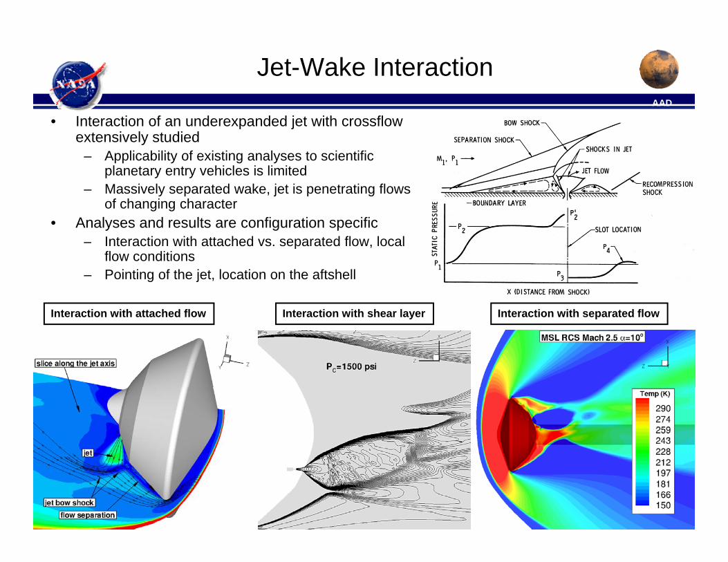
Jet-Wake InteractionAAD
• Interaction of an underexpanded jet with crossflow extensively studied
– Applicability of existing analyses to scientific planetary entry vehicles is limitedplanetary entry vehicles is limited
– Massively separated wake, jet is penetrating flows of changing character
• Analyses and results are configuration specific– Interaction with attached vs. separated flow, localInteraction with attached vs. separated flow, local
flow conditions– Pointing of the jet, location on the aftshell
Interaction with separated flowInteraction with shear layerInteraction with attached flow Interaction with separated flowInteraction with shear layerInteraction with attached flow
73/12/2008 7
AAD
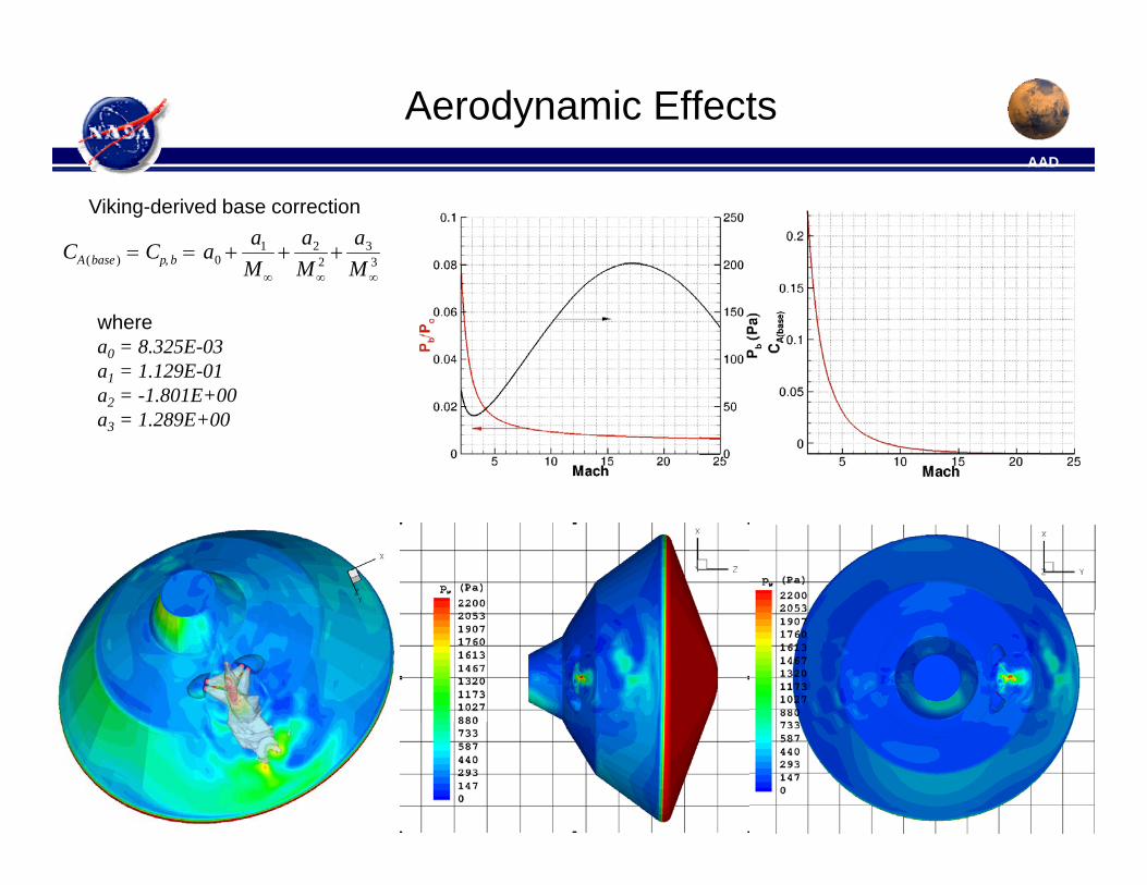
Aerodynamic EffectsAAD
CA(base ) = Cp, b = a0 +a1
M+
a2
M 2 +a3
M 3
Viking-derived base correction
M∞ M∞ M∞
wherea0 = 8.325E-03a1 = 1.129E-01a2 = -1.801E+00a3 = 1.289E+00
83/12/2008 8
AAD
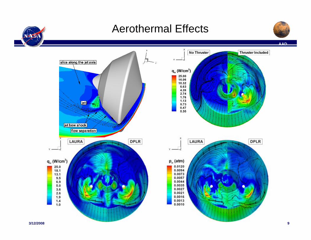
Aerothermal EffectsAAD
93/12/2008 9
AAD
RCS/Gasdynamic Interaction HeritageAAD
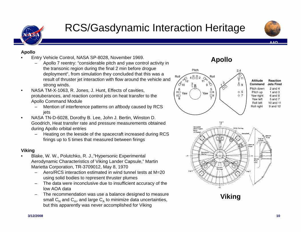
Apollo• Entry Vehicle Control, NASA SP-8028, November 1969.
– Apollo 7 reentry: “considerable pitch and yaw control activity in the transonic region during the final 2 min before drogue
“ f
Apollo
deployment“, from simulation they concluded that this was a result of thruster jet interaction with flow around the vehicle and strong winds.
• NASA TM-X-1063, R. Jones, J. Hunt, Effects of cavities, protuberances, and reaction control jets on heat transfer to the Apollo Command ModuleApollo Command Module
– Mention of interference patterns on aftbody caused by RCS jets
• NASA TN-D-6028, Dorothy B. Lee, John J. Bertin, Winston D. Goodrich, Heat transfer rate and pressure measurements obtained during Apollo orbital entriesg p
– Heating on the leeside of the spacecraft increased during RCS firings up to 5 times that measured between firings
Viking• Blake, W. W., Polutchko, R. J.,”Hypersonic Experimental
A d i Ch t i ti f Viki L d C l ” M tiAerodynamic Characteristics of Viking Lander Capsule,” Martin Marietta Corporation, TR-3709012, May 8, 1970
– Aero/RCS interaction estimated in wind tunnel tests at M=20 using solid bodies to represent thruster plumes
– The data were inconclusive due to insufficient accuracy of the low AOA data
103/12/2008 10
low AOA data– The recommendation was use a balance designed to measure
small CN and Cm, and large CA to minimize data uncertainties, but this apparently was never accomplished for Viking
Viking
AAD
SummaryAAD
• RCS can interfere with the aerodynamic characteristics of entry vehicle – Changes in aerodynamics occur in both supersonic and hypersonic segments of
th t t j tthe entry trajectory• Control gain and aerodynamic cross coupling can occur• In extreme cases the authority of RCS can be negated
– Computational and experimental analyses help bound the phenomena• Difficulties in both computational methods (wakes are hard to solve) and experiment
(moments are small in comparisson to the forebody moments)
• Impact of RCS on aerothermal evironments can be significant– Aeroheating increase by an order of magnitude depending on the specifics of the– Aeroheating increase by an order of magnitude depending on the specifics of the
jet interaction– Impact on TPS selection, cost, schedule
• Based on analyses performed to date, jet interaction with the flow around entry vehicle is better understood– � Paradigms have been developed to minimize destructive interference of RCS jets
113/12/2008 11
AADAAD
BACKUP
123/12/2008 12
AAD
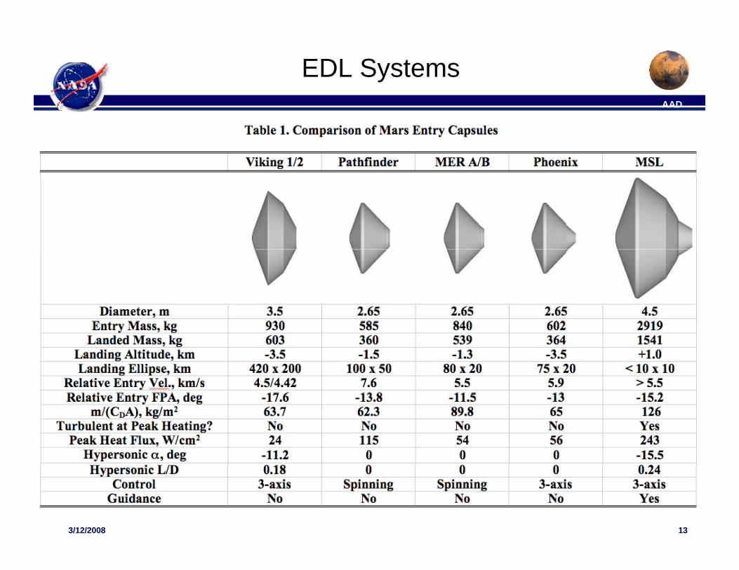
EDL SystemsAAD
133/12/2008 13
AAD
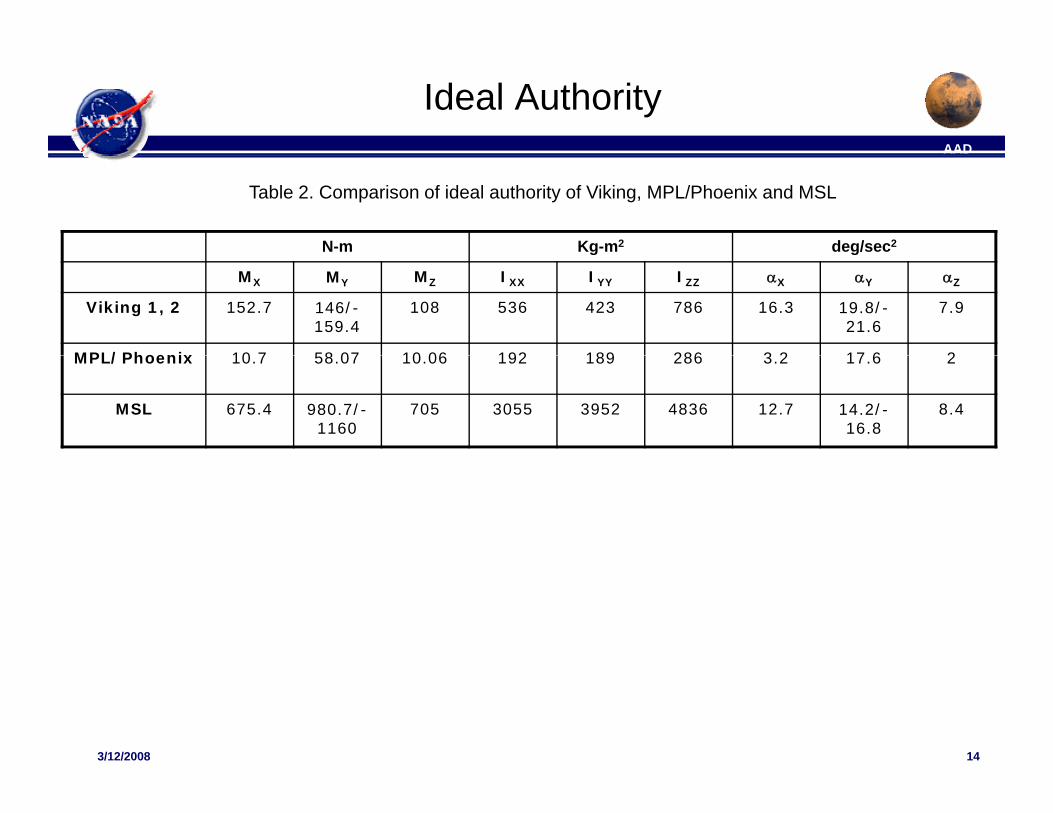
Ideal AuthorityAAD
N-m Kg-m2 deg/sec2
Table 2. Comparison of ideal authority of Viking, MPL/Phoenix and MSL
g g
MX MY MZ IXX IYY IZZ αX αY αZ
Viking 1, 2 152.7 146/-159.4
108 536 423 786 16.3 19.8/-21.6
7.9
MPL/Phoenix 10 7 58 07 10 06 192 189 286 3 2 17 6 2MPL/Phoenix 10.7 58.07 10.06 192 189 286 3.2 17.6 2
MSL 675.4 980.7/-1160
705 3055 3952 4836 12.7 14.2/-16.8
8.4
143/12/2008 14
AAD
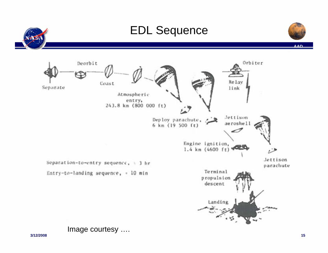
EDL SequenceAAD
153/12/2008 15
Image courtesy ….
AAD
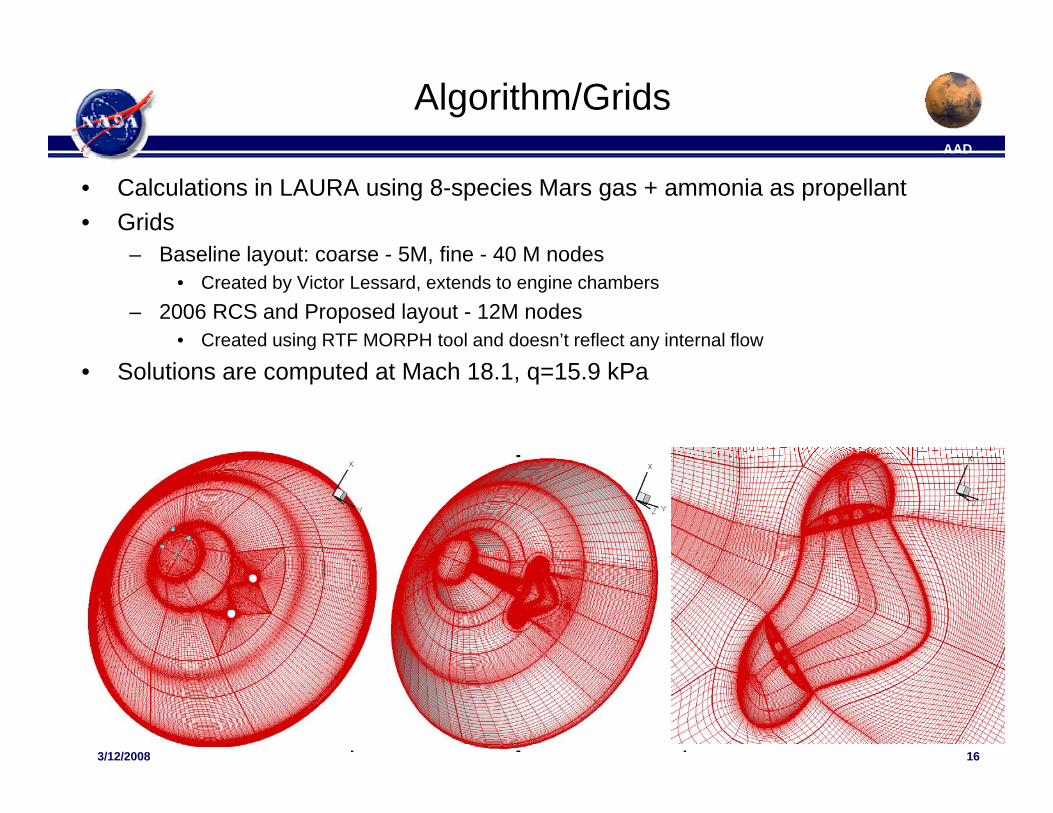
Algorithm/GridsAAD
• Calculations in LAURA using 8-species Mars gas + ammonia as propellant• Grids
Baseline layout: coarse 5M fine 40 M nodes– Baseline layout: coarse - 5M, fine - 40 M nodes• Created by Victor Lessard, extends to engine chambers
– 2006 RCS and Proposed layout - 12M nodes• Created using RTF MORPH tool and doesn’t reflect any internal flow
• Solutions are computed at Mach 18.1, q=15.9 kPa
163/12/2008 16
AAD
Geometric ConsiderationsAAD
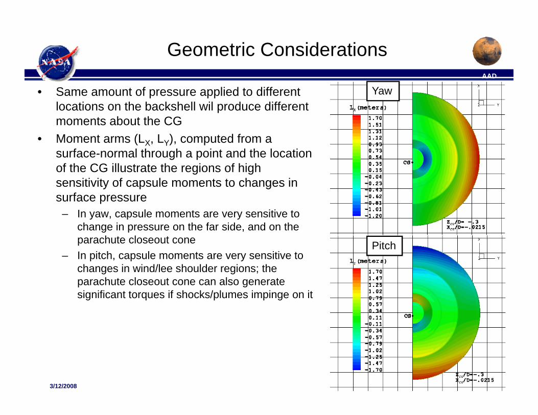
• Same amount of pressure applied to different locations on the backshell wil produce different moments about the CG
Yaw
• Moment arms (LX, LY), computed from a surface-normal through a point and the location of the CG illustrate the regions of high sensitivity of capsule moments to changes insensitivity of capsule moments to changes in surface pressure
– In yaw, capsule moments are very sensitive to change in pressure on the far side, and on the parachute closeout cone
– In pitch, capsule moments are very sensitive to changes in wind/lee shoulder regions; the parachute closeout cone can also generate
Pitch
p gsignificant torques if shocks/plumes impinge on it
173/12/2008 17
AAD
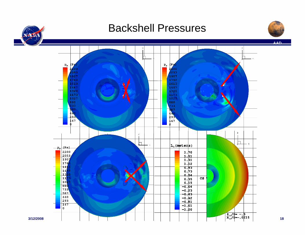
Backshell PressuresAAD
183/12/2008 18
AAD
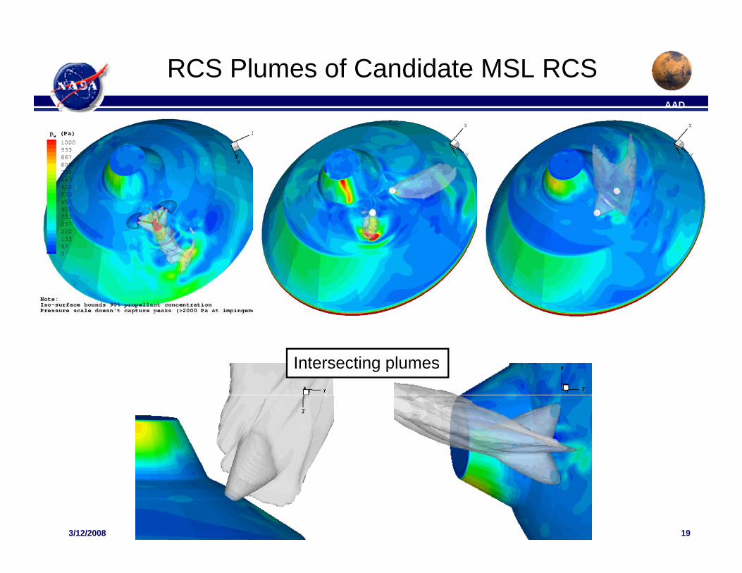
RCS Plumes of Candidate MSL RCSAAD
Intersecting plumes
193/12/2008 19
AAD
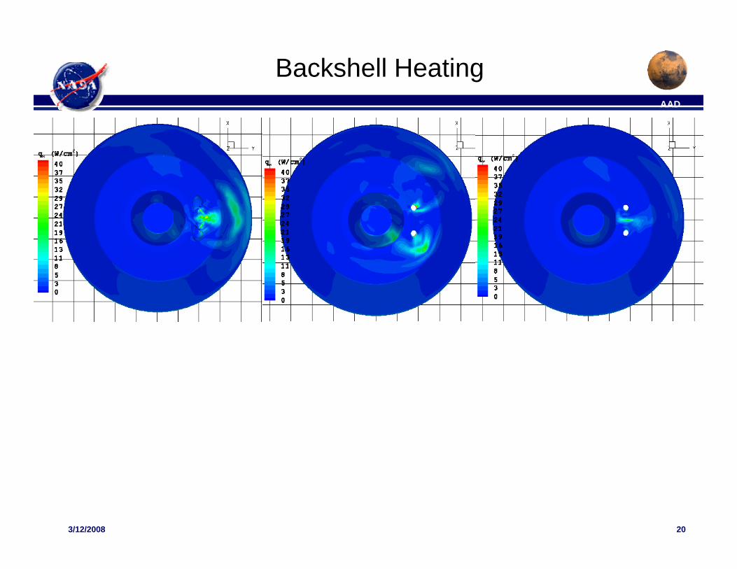
Backshell HeatingAAD
203/12/2008 20