Re: ENSC 340 Process Report for the Pace Maker Beat...
19
TM January 17, 2002 Dr. Andrew Rawicz School of Engineering Science Simon Fraser University Burnaby, BC V5A 1S6 Re: ENSC 340 Process Report for the Pace Maker Beat Recognition System Dear Dr. Rawicz: Enclosed please find our document, Process Report for the Pace Maker Beat Recognition System, outlining the design and implementation of our ENSC 340 project. Further more, this document details the issues we faced during the last semester and the experience we’ve gained from this course. Finally, this document provides information on the next step to be taken in the completion of this product and other relevant areas where the technology developed for this project can be applied. The Pace Maker system was designed for providing real-time feedback on the tempo of rhythm-oriented music. This feedback can be delivered in the form of a graphic or numeric display (as in our proof-of-concept design), or in the form of flashing lights or mechanical actuators. Four talented and dedicated senior engineers have created simplesmart, the company behind Pace Maker. The team consists of Dan Toews (CEO), Grzegorz M. Misa (VP Engineering), Prashan Gunasingam (CFO) and Yasaman Mohammadi (VP Operations). Any questions or concerns regarding the process of our product may be directed to us via email at [email protected]. Sincerely, Dan Toews CEO Enclosure: Process Report for the Pace Maker Beat Recognition System 0
Transcript of Re: ENSC 340 Process Report for the Pace Maker Beat...

TM
January 17, 2002 Dr. Andrew Rawicz School of Engineering Science Simon Fraser University Burnaby, BC V5A 1S6 Re: ENSC 340 Process Report for the Pace Maker Beat Recognition System Dear Dr. Rawicz: Enclosed please find our document, Process Report for the Pace Maker Beat Recognition System, outlining the design and implementation of our ENSC 340 project. Further more, this document details the issues we faced during the last semester and the experience we’ve gained from this course. Finally, this document provides information on the next step to be taken in the completion of this product and other relevant areas where the technology developed for this project can be applied. The Pace Maker system was designed for providing real-time feedback on the tempo of rhythm-oriented music. This feedback can be delivered in the form of a graphic or numeric display (as in our proof-of-concept design), or in the form of flashing lights or mechanical actuators. Four talented and dedicated senior engineers have created simplesmart, the company behind Pace Maker. The team consists of Dan Toews (CEO), Grzegorz M. Misa (VP Engineering), Prashan Gunasingam (CFO) and Yasaman Mohammadi (VP Operations). Any questions or concerns regarding the process of our product may be directed to us via email at [email protected]. Sincerely, Dan Toews CEO Enclosure: Process Report for the Pace Maker Beat Recognition System
0

TM
Process Report for the Pace Maker Beat Recognition System
Submitted by: Dan Toews Grzegorz M. Misa Yasaman Mohammadi Prashan Gunasingam
Submitted to: Dr. Andrew Rawicz (ENSC 340) School of Engineering Science Simon Fraser University Steve Whitmore (ENSC 305) School of Engineering Science Simon Fraser University
Date: January 17, 2002 Version: 1.1
Contact Person: Dan Toews, CEO simplesmart Inc. E-mail: [email protected]
www.sfu.ca/~ymohamma/simplesmart/
I
TM
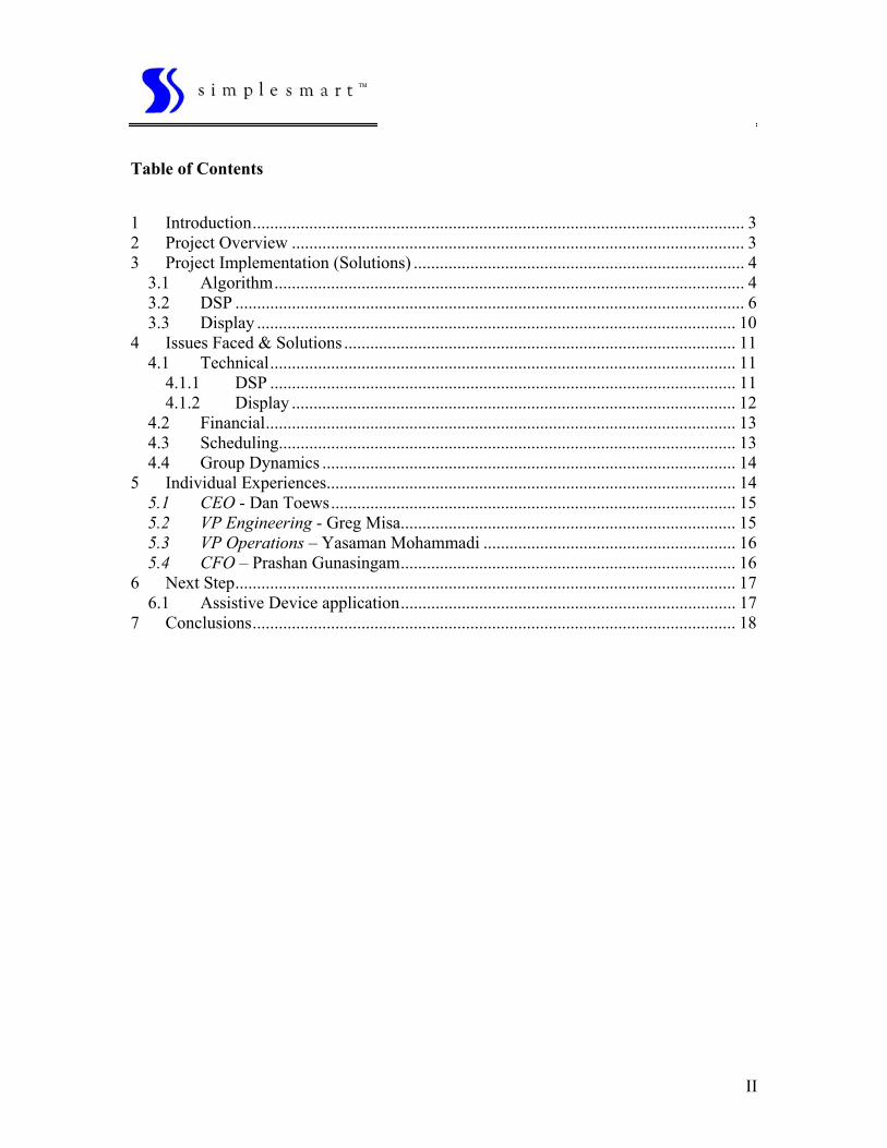
Table of Contents 1 Introduction................................................................................................................. 3 2 Project Overview ........................................................................................................ 3 3 Project Implementation (Solutions) ............................................................................ 4
3.1 Algorithm............................................................................................................ 4 3.2 DSP ..................................................................................................................... 6 3.3 Display .............................................................................................................. 10
4 Issues Faced & Solutions .......................................................................................... 11 4.1 Technical........................................................................................................... 11
4.1.1 DSP ........................................................................................................... 11 4.1.2 Display ...................................................................................................... 12
4.2 Financial............................................................................................................ 13 4.3 Scheduling......................................................................................................... 13 4.4 Group Dynamics ............................................................................................... 14
5 Individual Experiences.............................................................................................. 14 5.1 CEO - Dan Toews............................................................................................. 15 5.2 VP Engineering - Greg Misa............................................................................. 15 5.3 VP Operations – Yasaman Mohammadi .......................................................... 16 5.4 CFO – Prashan Gunasingam............................................................................. 16
6 Next Step................................................................................................................... 17 6.1 Assistive Device application............................................................................. 17
7 Conclusions............................................................................................................... 18
II
TM
1 Introduction
Music, unlike anything else in this world has the ability to transcend borders and languages, to bring forth passion in the hearts of all humankind.
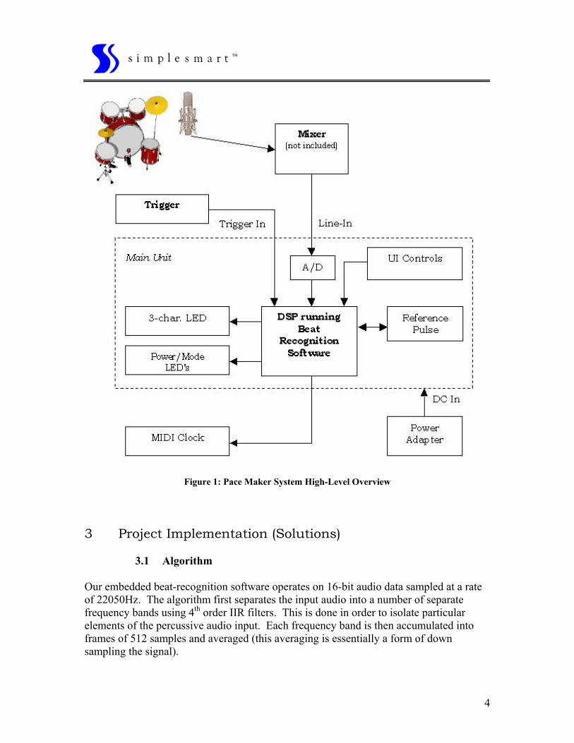
The focus of our company is on musical rhythm. Our goal is to produce products, which unobtrusively aid musicians with the development of their rhythmic skills. Very little effort has been put into the development of such products, until now. The direction of our research is in providing musicians with real-time feedback on their playing. This project started with an idea – to develop a system that could mimic the intuition that humans have in determining the tempo of music. Over the past four months, we have developed and implemented a proof-of-concept design of our beat recognition device designed for use by drummers and percussionists. Many different ideas were tested leading to the current implementation of the product. The completion of our proof-of-concept design, however, is not the end of this project. We are looking forward to the completion of a fully functioning hardware device, as well as applying the technology developed for this product to other projects. From other musician-related products to a device aimed at improving the experience of feeling music, for use by the def, this project has a very broad appeal. 2 Project Overview This project began with the goal of developing a system for performing real-time beat recognition. The Pace Maker is a musical beat tracking system designed for use by drummers and percussionists. By processing a musical performance in real-time with our embedded beat-recognition software, Pace Maker determines the current tempo of the music and provides this information to the musician in a useful and unobtrusive manner. The Pace Maker benefits drummers and percussionists by aiding them in the training of their rhythmic skills and intuition, and by presenting them with a level of control over the music they produce that has been previously unavailable. The Pace Maker beat detection system includes the following components: • Main unit including the processing hardware, tempo display and i/o connectors • Cymbal stand clamp and rack-mount hardware for the main unit • Trigger with hi-hat/cymbal stand clamp • Power adapter and trigger cable
3
TM
4
Figure 1: Pace Maker System High-Level Overview
3 Project Implementation (Solutions)
3.1 Algorithm Our embedded beat-recognition software operates on 16-bit audio data sampled at a rate of 22050Hz. The algorithm first separates the input audio into a number of separate frequency bands using 4th order IIR filters. This is done in order to isolate particular elements of the percussive audio input. Each frequency band is then accumulated into frames of 512 samples and averaged (this averaging is essentially a form of down sampling the signal).

TM
The averaged frequency bands are then fed into the beat candidate detection algorithm. The outputs of these blocks then feed the final heuristic tempo detection routine, which chooses the most likely tempo estimate. below gives an overview of the whole system.
Figure 2
Figure 2: Beat Detection Algorithm Overview
The beat candidate detection blocks operate on the principle of resonant comb-filter banks. By processing the averaged signal bands with a series of comb filters, each with a slightly varying length, the filter which corresponds to the tempo of the music will have a higher energy output than the other filters in the bank. What this means is that each separated frequency band of the input signal is processed by a series of comb filters, each of which corresponds to a particular tempo (BPM). The energies from these comb-filter banks are then fed into a block which performs a heuristic analysis of the tempo.
5

TM
3.2 DSP
The DSP integration is the hardware implementation of MATLAB simulation. The high level structure of the implementation is discussed below.
1. Sampling the audio signal at high frequency. 2. Down sampling and averaging the sampled signal. 3. Processing the averaged signal. 4. Output to display device.
The detailed procedure is given below.
• The PCI DSP board was installed on a desktop PC. • IRQ conflicts caused the board not to function properly. The firmware was not
responding due to IRQ conflict, hence the software could not be run. • It was discovered that the emulator on the board was broken because of the IRQ
conflict. • A new board was installed. • The software was working fine. • The compiler, linker, and loader of the software were not directly linked to the
hardware. This was discovered through trial and error. • Direct implementation of the file, compiling, linking, and loading of the file was
done through console.
6

TM
7
Figure 1. EVM audio Interface First, the standard output of the complier, which is linked with the DSP board via the PCI card, was tested. Secondly, sampling on the c6x EVM board, there is a 16-bit codec that performs the analog-to-digital conversion with sampling frequencies ranging from 5.5 to 48 KHz. The codec is fully programmable from C and assembly. We used available C library function to rest, initialize, and run the codec. Processing samples of a signal can be done within an ISR (interrupt service routine). The processor halts whatever it is processing and goes to a specific location in memory to execute and ISR. The interrupt can be issued externally or internally. There are four external interrupts and twelve internal interrupts possible on the C6x. these interrupts are prioritized. The RESET is considered to be an interrupt having the highest priority. The audio signal sampling is described next. There are three 3.5-mm audio jacks on the back of the EVM that allow for a microphone in, a line in, and a line out. The codec is connected to the D62 DSP through its multi-channel buffered serial port (McBSP). Each of the audio jacks has its own amplifying and filtering capabilities. (Refer to figures 4-5 and L3-1 on pages 54 and 55 of C6x-based). Codec library is supplied in the archived object library file drv6x.lib. The codec library has so-called API (application program interface) functions that can be used to configure and control the operation of the codec.

TM
8
Figure 2. Interrupt service routine Initializing EVM and Codec was next in line. In writing a program that uses the codec to sample an incoming analog signal, several initializations have to be performed. Among these are the initialization of the EVM, McBSP, and codec. The sampling rate for the codec has to be set, as well as any gain adjustment in the input ADC and output DAC. Once the required initializations are made, an interrupt needs to be assigned to the receive register of the codec to halt the processor and jump to an assigned interrupt service routine. The final program will output the same input sample to the codec for audio or video display After completing the code for a sampling program that samples an analog signal, such as the output from a CD player connected to the line-in port of the EVM and generates and interrupt that calls a simple ISR, was tested. This simple ISR is used to receive samples from the McBSP and send them back out, unprocessed for the time being. To test this code, the line out from a CD player was given into the line-in input of the DSP. This was finally sent out to the speaker where the output was verified. Next, the circular buffer and the FIR filter were implemented. These issues are discussed below. In our DSP application algorithm, implementing the bank of comb filters, we need to deal with a moving window: circular buffer in is an addressing mode by which a moving-

TM
window effect can be easily created. In a circular buffer, if a pointer pointing to the last element of the buffer is incremented, it is wrapped around and pointed back to the first element of the buffer. This proves an easy mechanism to exclude the oldest sample while including the newest sample creating a moving-window effect.
Figure 3. Circular Buffer
A 32-coefficient FIR filter is used to implement low-pass, band-pass, and high-pass filters for the application. To do this in C, an additional buffer of length 32 is needed. Two arrays are required: one for the input buffer and the other for the coefficients of the FIR filter. Initially all data in both affrays are zero. The signal is filtered by computing the dot products of the coefficients and the inputs. In our algorithm we used elliptical FIR filter coefficients of order 6 which were computed and normalized in MATLAB. The resultant FIR filters had acceptable signal to noise ratio value, which was sufficient for our purposes.
9

TM
3.3 Display
The two main issues involved in developing the hardware display were: What type of display to use and how to interface it with the DSP board. Below is a block diagram of our final synthesis of the hardware and its interface.
Figure 3: Hardware display and its interface.
1. Selecting the appropriate display unit. We had a couple of options with the display unit. We could either implement an LCD display or an LED display. Our decision was to go with the LED display for several reasons. One is that it provided a large and bright display, which was of great importance. Another advantage in using the LED’s was the simplicity in its implementation. And finally, LED are very cost effective compared with the LCD display. We refrained from using the LCD for the following reasons: The display would be unclear, and to provide a large enough display would require a significant cost, also the implementation would be more complex as compared to the LED’s. The specifications required that the unit be able to display numbers up to 3 digits. Therefore, we required three 7- segment LED displays to do this.
10
TM
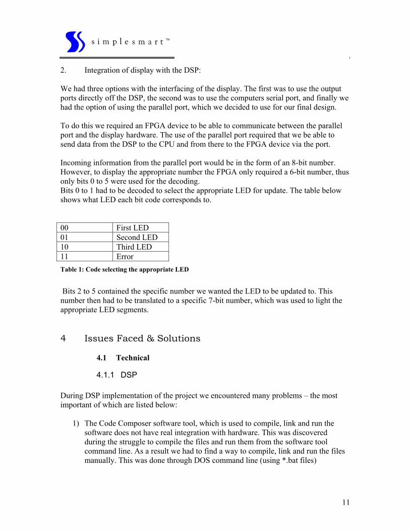
2. Integration of display with the DSP: We had three options with the interfacing of the display. The first was to use the output ports directly off the DSP, the second was to use the computers serial port, and finally we had the option of using the parallel port, which we decided to use for our final design. To do this we required an FPGA device to be able to communicate between the parallel port and the display hardware. The use of the parallel port required that we be able to send data from the DSP to the CPU and from there to the FPGA device via the port. Incoming information from the parallel port would be in the form of an 8-bit number. However, to display the appropriate number the FPGA only required a 6-bit number, thus only bits 0 to 5 were used for the decoding. Bits 0 to 1 had to be decoded to select the appropriate LED for update. The table below shows what LED each bit code corresponds to. 00 First LED 01 Second LED 10 Third LED 11 Error Table 1: Code selecting the appropriate LED
Bits 2 to 5 contained the specific number we wanted the LED to be updated to. This number then had to be translated to a specific 7-bit number, which was used to light the appropriate LED segments.
4 Issues Faced & Solutions
4.1 Technical
4.1.1 DSP During DSP implementation of the project we encountered many problems – the most important of which are listed below:
1) The Code Composer software tool, which is used to compile, link and run the software does not have real integration with hardware. This was discovered during the struggle to compile the files and run them from the software tool command line. As a result we had to find a way to compile, link and run the files manually. This was done through DOS command line (using *.bat files)
11

TM
2) The FIR filter coefficients had to be calculated mathematically. However, due to
real world hardware limitations, the ideal mathematical models that we calculated were not accurate enough for our purposes, hence we had to find new algorithm for our filters from which the FIR coefficients could be calculated. Using sophisticated math and communication system theory, we were able to find the proper filter coefficients.
3) Many C functions were not accessible in the library of the Code Composer tool. As a result, huge amount of coding was sometimes necessary in order to do a specific function (for example instead of using pointers and linked lists to create the circular buffers needed for the bank of comb filters, we had to use arrays and hence not very efficient algorithm to do calculations.
4) The memory map of the linker file that we used was not always proper for a specific implementation. Therefore a huge deal of effort had to be spent on learning the exact process of memory linking from software to hardware on DSP, so that the code would be easily downloaded to the hardware and run from the window command line.
5) The “printf” function during interrupt service routine of the algorithm caused extensive problems due to the limitation of hardware sleep and the amount of cycles that is needed to print to the command line. Hence the debugging of the code was rather difficult since it was almost impossible to use “printf” functions to see the real time value of the variables we needed to observe real time.
6) The amount of noise going through the LINE IN analog input was sufficient enough to cause inaccurate results in our algorithm. Hence we had to optimize the theoretical model (made in MATLAB) to make it more hardware friendly in terms of hardware limitations.
7) As there were no digital bus interface from the DSP board to a dependant daughterboard, an external parallel port was needed to be configured in order to output data into the display device we had built. This needed a complete interface of the DSP board PCI bus and the processor. Unfortunately, due to the limitations of the C library of the Code Composer software tool, this task became increasing tedious and troublesome. But using the correct parallel bus system configuration we were able to transfer data from the DSP PCI bus system into the running processor.
4.1.2 Display Then main technical issue involved the interfacing of the display unit. Our initial effort was to directly use the digital output ports of the DSP. This however would require the use of a micro-controller for proper synchronization. Our next attempt was to us the serial port of the computer to send the information to the FPGA. This as well required synchronization, which would involve a micro-controller. And finally we found the parallel port as the most effective method of integration. This would only require some simple VHDL code to provide the handshaking procedure.
12

TM
Another issue we faced was to design a voltage regulator, which would reduce the 12 Volts coming from the parallel port to a 5 volt max input into the FPGA board. This design required the use of a couple operational amplifiers.
4.2 Financial Sources for financial assistance were provided by the EUSS and the ENSC340/ENSC305 administration committee. Like with any project, we had to determine the cost specifics of our project before applying for funding. We found this to be quite challenging given our limited experience in this area. Also, the risk of not acquiring anticipated funding forced us to be very conservative in our estimates. We had to find a balance between getting what we considered essentials and luxury items. Once a baseline cost estimate was determined we applied for funding. This process was done in parallel with find sources to donate required system components. Some devices, such as the DSP kit, were financially beyond our reach. We had to primarily rely on SFU engineering faculty to provide us with some help. This process inherently contained significant risk. It was not expected that everyone was willing to entrust a group of students with a $1000(USD) DSP solutions kit. Also, the turn around time to receive the funding did not coincide with our ideal timeline for purchasing key components. This was mitigated by personal funding and donations. Even though, additional funding was available through our lab facilities it was not easy to acquire required components. This brought with it a sense of false security in many cases. Along with the acquisition of funds came obligation towards our donors. We found that our timeline didn’t remotely correspond to that dictated by the sponsor. i.e. demo of working product at a mush earlier date than expected. This will be further discussed in the Scheduling section that follows.
4.3 Scheduling As in any project, the process of scheduling was iterative in nature. We found that in retrospect our initial and final schedule were quite different. In determining timelines we focused more on the overall completion of the project. Even though this was a good starting point, we really needed to map out interdependencies of sub tasks along with their timelines. In many cases we found ourselves waiting for some other task to be completed.
13

TM
Also, many issues that we considered easy, in which case little or no time was allocated, turned out to take a lot of time and resources. Note that the converse was not true for the most part. We also noticed that most of the process documents that were required for this project were idea-to-product oriented. Given that this was primarily a research-based project, we found ourselves having to anticipate a lot of the content that were required by some documents. This inability to effectively communicate the ideals of our project had a domino effect on the motivation and general outlook of our team members. Over time, as various aspects of the project came together a more positive attitude was observed. Also, unforeseen technical issues along with unexpected occurrences, such as software licensing issues and burnt DSP boards, had a tremendous impact on our overall scheduling. Even though these can be anticipated as risk we found ourselves financially insecure to mitigate some risks. It is also worthy to note that the structure in which ENSC340 was setup, though demanding, helped us take this project to completion with a span of four months. This wouldn’t have been the case given an independent approach to designing a concept prototype.
4.4 Group Dynamics Group dynamics played an immediate and important role in the progress of this project. The initial stages were filled with chaos, from a project viewpoint. However, everyone progressively assumed a key role that ultimately attributed to the success of our project. These roles were defined by skill set and personal interest. These roles varied from undertaking of essential system components to administrative roles. The lead role was played by different member of the team at different times. Generally, the rest of the team would feed of the success of an individual. This seemed to work well when progress was slow. Also, we found ourselves switching tasks when appropriate. This was primarily done to assist a fellow member of the team. This helped motivate one another to carry out a task to completion. Overall, we found that our skill sets and strengths complemented each other’s quite well. This, along with a lot of constructive criticism resulted in great learning experiences for everyone. 5 Individual Experiences
14

TM
5.1 CEO - Dan Toews
ENSC 340 has been a very valuable course in many respects. To begin with, this course offered us our first real experience of initiating a project from scratch and seeing it through to the end. The fact that nothing was laid out before us at the beginning of the semester really forced us to take into consideration numerous elements of engineering, project development, and project management that we had never considered before. One of the most important things I’ve learned through taking 340 is the importance of proper setup. Whether it means getting and learning the necessary tools, or taking initial steps to properly outline the entire project and ensure that all members of the group are on the same page as to where the project is going, setup is key. I’ve also become more aware of the importance of setting up smaller objectives to be met on a regular basis. By breaking the design work down into small experiments and tasks, rather than just setting deadlines for the “final” results, each member of the design group can be better kept up to date on the other’s progress, and the process of the design can be more easily documented. Finally, I’ve enjoyed the experience of working with a group of very talented people. The project we undertook wasn’t an easy, clear application of something we were already adept in. Rather, this project required each member of the group to go out and learn new skills and new software, as well as develop some very resourceful solutions to some unusual problems. I hope I have another chance to work with this group again soon.
5.2 VP Engineering - Greg Misa This project provided me with a great opportunity to learn and work with an excellent group of people. I found the experience a very rewarding one. It taught me the importance of team effort and cooperation, and also helped me develop my inter-personal skills. One important thing I discovered when working on a project is the necessity of proper planning and having the proper setup before commencing the design. A well-planed project will prevent many unnecessary mistakes and problem, as well as provide each member of the group with a clear idea of what their task is. Proper setup and equipment will prevent much frustration and will save a great deal of time. This became very apparent during the course of the project development and implementation. Another important lesson I’ve learned was to try different approaches if one seems to complex for the task at hand. Very often there is a much simpler solution to what one tries initially. Also, I realized that there are many solution already developed to problems
15
TM
you may be trying to solve. Therefore, it is worth the while to search for components or designs already created by others and apply them to your problem. All in all, although at times frustrating and exhausting, I found the experience a very valuable and rewarding one. It provided me the skills and knowledge necessary to make the development of other projects to come less difficult and more constructive.
5.3 VP Operations – Yasaman Mohammadi During this project I found the opportunity to work and interact with three other engineering students with different background and skills. I have found this experience to be a non-matching and unique one since my academic studies at SFU. Working in this group has served me as an excellent source of inter-personal, social, and technical skills. During working on the project I got to know and understand the importance of flexibility, planning, analysis, and problem solving skills. As for my primary work on DSP, I found this technology to be very powerful and rewarding. Yet, there are so many problems associated with precision and programming. Through one unpleasant experience of *almost* frying the DSP board we desperately needed to get working, I learned how much a good design is important for any product to be safe from and prone to the customers mistakes and accidents. As a result, we decided that our product should serve the customer the same friendly way. Also, working on the project has taught me how much co-ordination with other members of the group is important in order to be able to integrate the product from all software, hardware, user interface, financial issues, feasibility and compatibility aspects. I think that I had the best of people to work with during the semester, and there is nothing that could ever top the experience I had technically and socially with these people.
5.4 CFO – Prashan Gunasingam This project, being the first of it’s kind, brought forth many challenges and unique learning experiences. I had a chance to get to know fellow engineers while learning to work in a dynamic team environment. As this was primarily a research-based project, the uncertainties that settled earlier on in the project was something I had to overcome. Also, most of the work I did was new to me; which meant a lot of time spent learning so that I can apply concepts and technology towards the project. This proved to be a great way of learning how to self-learn. Along with this, I was also able to get some experience in ordering commercial parts and getting
16

TM
samples. As trivial as this task maybe, most often knowing where to look is not as straightforward. Lastly, I learnt that being setup to perform a task would greatly reduce the time spent on solving a problem. Also, being able to do things quickly and efficiently will have a positive effect on one’s attitude. Apart from all these issues, I had a great time hanging out with my fellow team members. 6 Next Step The next step in the design of the Pace Maker system is to complete a fully functioning hardware prototype of the product. Through the work we completed in this course, we are confident that there is indeed a market for this product, and that it would be unique and useful to a number of people. In addition to constructing a hardware prototype, the embedded software needs to be further developed and tested with a wide variety of rhythms and music styles. As well, we plan to integrate our beat-recognition system with a digital metronome, creating a low-cost device, which could possibly capture the market on rhythm assisting devices.
6.1 Assistive Device application One of the most interesting applications of our product is in assisting the hearing-impaired. Our beat detection system can easily be modified to provide feedback on the tempo of music to the def. One application is to accompany music with an interpretive light display, in order to enhance the experience of listening to music for the hearing-impaired. With our beat-recognition technology, a system could be devised to lock onto the tempo of a music source and translate certain elements of the sound into a light display in real-time. Another exciting application would be a dance-assistant device. By detecting the tempo of music in real-time, a hand-held device could be connected to a mechanical vibrator, attached to a person’s body. This device could be worn to a club (or in any situation where the user would want to dance) and would translate the air pressure into a vibrating pulse in-time with the rhythm of the music.
To this end, we are considering applying to SOLUTIONS – an annual design exposition for technologies aimed at the assistive device and health technologies.
17

TM
18
7 Conclusions We feel this was a very successful project. The algorithms we developed, as well as the DSP and LED display work we did, have laid the groundwork for future development of this product (and other related projects).