Re-Engineering of Stators of Three Phase Traction Motors Type 6FRA 6068 Used in(1)
13
Page 1 of 13 Re-engineering of Stators of Three phase Traction Motors type 6FRA 6068 used in WAG9/WAP7 locomotives for Improving their Reliability R.N.Lal ,Senior Executive Director Standards , Ganesh , Director Standards Electrical Directorate , Research Design and Standards Organisation , Lucknow Abstract Insulation and brazed joint failures in the stators of three phase traction motors used in electric locomotives on Indian Railways are primarily on account of excessive shock and vibration and unsupported long length overhangs. Failure of stators contributes to 60% failure of GTOs of the power converters. Based on the trial data and study of literatures , two possible solutions have been proposed in the existing structure of stators which have been tried on stators and validated with the help of Finite Element Analysis for the first time on IR. This analysis reveals that by supporting the overhangs of stators reduces the stress level drastically. Apart from supporting the overhang, augmentation in insulation scheme and improvement in manufacturing practices have also been done. After evaluating these two schemes from point of view of ease of manufacturing, one of them, has been adopted by Indian Railways for repairing and new manufacturing. These schemes are going to have annual saving Rs. 36.24 Crore. vR;kf/kd 'kkWd vkSj okbcjs'ku dh otg ls 3 Qsl VªSD'ku eksVj ds LVsVj esa czsd IokbaV vkSj balqys 'ku dh foQyrk gks x;h gSA ikoj dUosUVj ds 60% thVhvks dh foQyrk dk dkj.k Hkh LVsVj dh mijksDr foQyrk gSA Vªk;y MkVk vkSj miyC/k fjlpZ isij ds v/;;u ds ckn nks Ldhe dks fodflr fd;k x;k gS ftls Hkkjrh; jsy esa igyh ckj ,QbZ, ds ek/;e ls oSyhMsV Hkh fd;k x;k gSA LVsVj ds vksoj gSax dks blds Qsze ds lkFk cak/kus ls okbafMx esa LVªsl de gks tkrk gSA bu nksuksa Ldheksa esa ls lokZf/kd mi;qDr ,d Ldhe dks Hkkjrh; jsy esa dk;Z;kfUor fd;k x;k gSA blds vfrfjDr balqys'ku Ldhe esa Hkh lq/kkj fd;k x;k gSA LVsVj esa lq/kkj dh otg ls Hkkjrh; jsy dks yxHkx 36-26 djksM+ dh okf"kZd cpr gksxhA 1. Introduction Indian Railways introduced three phase electric locomotives in late 1990s for obtaining advantages of higher power, regeneration during braking and superior technology. While the benefits of technology, power & regeneration have been realized, employment of 3 phase induction motors, in the WAG9 variety operating in heavily graded sections of ER/EC Rly and hauling heavy loads of 58 N Boxes, have a higher rate of arising. Similar problem have been reported from three phase traction motors in the diesel locos of IR. Other Railway systems overseas have had similar experiences with axle hung nose suspended three phase traction motors. RDSO has made an effort to study various available literatures on the three phase traction motor and manufacturing practices of some of the leading motor manufacturers and had interaction with some of the designers of these motors. Assistance of Indian motor manufacturers/repairers were also sought to validate the various designs which could be finalised after study. This paper recommends modification which can be adopted on the existing traction motors whenever they are taken for repair as well as covers the improved design parameters for manufacturing of motors in future. It is expected that with the implementation of these modification the problem of failure in stators and in turn failure of GTO will be minimised/eliminated. This paper discusses the failure of Stators along with proposed solutions recommended by RDSO. Action plan to improve the reliability of rotors of three phase tractions motors is being dealt separately.
Transcript of Re-Engineering of Stators of Three Phase Traction Motors Type 6FRA 6068 Used in(1)
Page 1 of 13
Re-engineering of Stators of Three phase Traction Motors type 6FRA 6068 used in WAG9/WAP7 locomotives for Improving their Reliability
R.N.Lal ,Senior Executive Director Standards , Ganesh , Director Standards
Electrical Directorate , Research Design and Standards Organisation , Lucknow
Abstract
Insulation and brazed joint failures in the stators of three phase traction motors used in electric locomotives on Indian Railways are primarily on account of excessive shock and vibration and unsupported long length overhangs. Failure of stators contributes to 60% failure of GTOs of the power converters. Based on the trial data and study of literatures , two possible solutions have been proposed in the existing structure of stators which have been tried on stators and validated with the help of Finite Element Analysis for the first time on IR. This analysis reveals that by supporting the overhangs of stators reduces the stress level drastically. Apart from supporting the overhang, augmentation in insulation scheme and improvement in manufacturing practices have also been done. After evaluating these two schemes from point of view of ease of manufacturing, one of them, has been adopted by Indian Railways for repairing and new manufacturing. These schemes are going to have annual saving Rs. 36.24 Crore.
vR;kf/kd 'kkWd vkSj ok bcjs'ku dh otg ls 3 Qsl VªSD'ku eksV j ds LV sVj e sa c zsd I ok baV vkSj
balqy s'k u dh foQyr k gks x; h gSA ik oj dU o sUVj ds 60% th Vhvk s dh foQyr k dk dk j.k Hkh LV sVj dh mijk sDr fo Qyrk gSA Vªk ;y MkV k vkSj miyC/k fj lpZ isij ds v/;;u ds ckn n ks Ldhe dk s f odf lr fd;k x;k gS f tls Hkkjrh ; jsy e sa i gyh ck j ,QbZ, ds ek/ ;e ls o SyhMsV Hkh f d;k x ;k gSA LVsVj ds vksoj gSax dks blds Q sze ds lkFk cak/ku s ls okb afMx e sa LV ªsl de gk s tkrk gSA bu n ksuksa Ldheksa esa l s lokZf/k d m i;qDr , d Ldh e dks Hk kjrh; jsy e sa dk;Z;k fUor fd;k x;k gSA b lds v frfjDr balqys'k u Ldhe e sa Hkh lq/kkj f d;k x;k gSA LVsV j e sa lq/kk j dh otg ls Hkkjr h; jsy dks yx Hkx 36-26 djk sM+ dh okf"k Zd cp r gksxh A
1. Introduction Indian Railways introduced three phase electric locomotives in late 1990s for obtaining advantages of higher power, regeneration during braking and superior technology. While the benefits of technology, power & regeneration have been realized, employment of 3 phase induction motors, in the WAG9 variety operating in heavily graded sections of ER/EC Rly and hauling heavy loads of 58 N Boxes, have a higher rate of arising. Similar problem have been reported from three phase traction motors in the diesel locos of IR. Other Railway systems overseas have had similar experiences with axle hung nose suspended three phase traction motors.
RDSO has made an effort to study various available literatures on the three phase traction motor and manufacturing practices of some of the leading motor manufacturers and had interaction with some of the designers of these motors. Assistance of Indian motor manufacturers/repairers were also sought to validate the various designs which could be finalised after study. This paper recommends modification which can be adopted on the existing traction motors whenever they are taken for repair as well as covers the improved design parameters for manufacturing of motors in future. It is expected that with the implementation of these modification the problem of failure in stators and in turn failure of GTO will be minimised/eliminated. This paper discusses the failure of Stators along with proposed solutions recommended by RDSO. Action plan to improve the reliability of rotors of three phase tractions motors is being dealt separately.

Page 2 of 13
2. Performance review of three phase traction motor(type 6FRA 6068) In order to have better appreciation of the gravity of problems of three phrase traction motors and its related equipments like temperature and speed sensors, the performance of three phase traction motor of Electric Loco shed Gomoh, and Ajni is given as under :
2004-05 2005-06 2006-07
GMO AQ GMO AQ GMO AQ
Stator FRCPY 14.3 3.0 22.6 2.2 22.5 1.0
Rotor FRCPY 14.6 3.0 25.0 2.2 19.8 1.0
Temp Sensor FRPCPY
3.4 27.2 8.9 20 4.8 6.3
Total Lifting per 100 locos
273 127 389 147 351 61
It can be seen from above that there are higher incidences of failure and loco lifting cases at Gomoh Shed than at Ajni which is primarily on account of the fact that their locos are being used for hauling loads in graded sections and coal sidings tracks which offer poor adhesion. The problem gets aggravated due to excessive shock and vibration and inappropriate slip slide control of locomotives. It is worthwhile mentioning that locomotive is required to be lifted for attending temperature sensor .RDSO has already issued modification which will prevent lifting of locomotive for attending temperature sensor.
3. Stator Failure Failure data collected from ELS, GMO, AQ and GZB has been analysed. RDSO has carried out a study based on data of from TMW, Nasikroad, also, on failure of stators.
Main failures in stators are listed below:
• Inter turn short/flashed in Overhang (NDE & DE)
• Stator Winding Earthed/Flashed with Slots(NDE & DE)
• Temperature Sensor Defective
• Junction Box Flashed
• Stator Rubbed with rotors
To avoid lifting of locomotives for replacement of temperature sensors , RDSO has issued a Modification Sheet RDSO/2007/EL/MS/0350 ,Rev 0 vide RDSO’s letter no. EL/3.2.182 dt 01.11.2007 introducing threaded type mounting arrangement of these sensors. Speed sensors play very important role in an effective slip slide control of locomotives. This problem is being addressed by development of active sensors based on Hall Effect and Doppler Effect.
4. Rewinding at TMW ,NK TMW, Nasik has re-wound so far 101 three phase stators with different makes , both modified ( with 9 mm cord winding support) and unmodified stators. Faults recorded by TMW before re-winding is collected and analysed and major observations are as under :
• 21% failure of stators is on account of rotor bars crack and balance 79% is exclusively on account of stators only.
21%
79% Stator Failure due to Rotor due to winding defects Stator Failure due to winding defects

Page 3 of 13
6 8 %
2 7 %
4 % 1 %
N D E F a i l u r e
D E F a i l u r e
N D E & D E F a i l u r e
O t h e r s
1 3 %
2 7 %
6 0 %
N D E C o i ls F la s h e d &e a r t h e d w i t h c o r e
N D E O v e r h a n g C o i ls
m e lt e d & p a r t e d a t S lo t
N D E O v e r h a n g c o i l
lo o p s f a i le d a t B r a z i n g
5 7 %
3 8 %
5 %
D E O v e r h a n g o n ec o i l m e lt e d a n dp a r t e dD E o n e c o i l m e lt e d a ts lo t e d g e / i n s id e s lo t s
O t h e r s
• If we analyse location wise stator failure , it is 68% on NDE side whereas just 27% on DE side.
• Out of these ,NDE side winding failure, 87% are on account of inter-turn short on overhang or brazing failure on joints.
• Similarly , DE end failure has also been analysed and 95% failure is contributed by grounding with slot and failure in overhangs
• ,All makes of TM Stator are failing and pattern of failure is same across the makes.
5. Investigations :
5.1. Measurement of Shock & Vibration on Stators
5.1.1. BT carried out Shock and Vibration Trials on WAG9 Locomotives to measure the max.
shocks to which traction motors are exposed . This trial was conducted with new as well as worn out pinions. Data for stators follows :
• Even with new pinion , shock and vibration level goes upto 14 g against the design assumption of 8-10 g in dynamic loading condition.

Page 4 of 13
Static Load
Dynamic Load
new gear worn gear
• Shock level multiplies by three times (40g ) with worn out pinions (BTL-77.68). Because of excessive wear in pinions and its inadequate supply, the pinions are running with further low value of BTL ( 77.68 to 77.42)
• With worn out pinion , shock and vibration level goes upto 89 g against the design assumption of 30g in static loading condition.
5.1.2. While studying the cause of rotor bar cracks in three phase traction motors of GM
locomotives ,SIEMENS has carried out Shock and Vibration Trials for GM Diesel Locomotives to ascertain the shocks to which traction motors are subjected . Max. value : 130g.
5.1.3. SIEMENS has carried out similar trials for MRVC projects in Mumbai sub-urban area before
designing the propulsion system. Max. value : 32 g
6. Stator Design Philosophy
RDSO has studied available designs of stators in service on Indian Railways and in abroad.
6.1. Design philosophy , followed by SIEMENS is given below :
Page 5 of 13
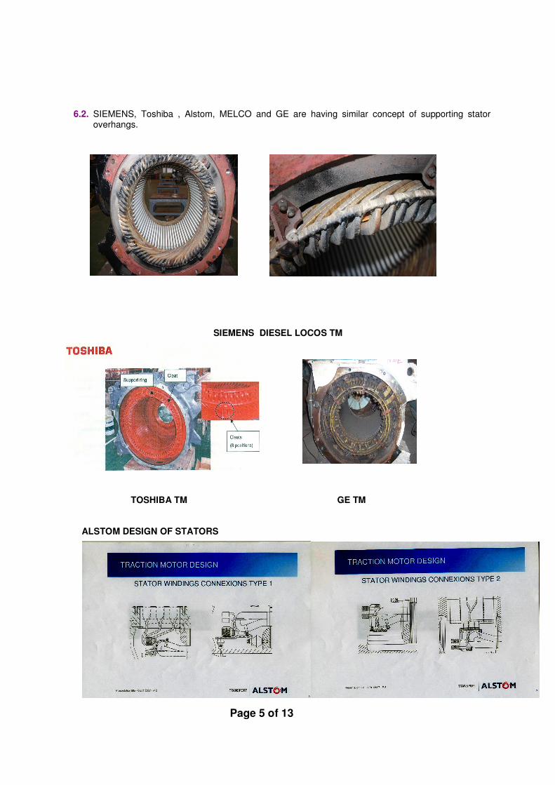
6.2. SIEMENS, Toshiba , Alstom, MELCO and GE are having similar concept of supporting stator overhangs.
SIEMENS DIESEL LOCOS TM
TOSHIBA TM GE TM
ALSTOM DESIGN OF STATORS
Page 6 of 13
6.3. For all types of mainline traction motors Toshiba provides both winding support ring and frame support and their design is suitable for shock level of 40g.
6.4. In a recent presentation made by BT, failure of overhangs of traction motors supplied by BT in
SBB project was discussed , which have been contained by supporting the overhangs with the frame.
6.5. Probable Causes:
6.5.1. Overhangs of existing traction motors are not supported, only 9 mm dia cord is provided on NDE side winding for bracing of winding overhang. There is neither Winding Support Ring nor Frame Support in the existing traction motors with 167 mm long overhang on NDE and 135 mm long overhang on DE.
6.5.2. M/s BT in their report of shock and vibration measurement, carried out on WAG9
locomotive has clearly indicated that they have designed WAG9 traction motor for much lower shock and vibration level based on the experience of Korean Railways.
6.5.3. Measurement of weight of overhangs at TMW ,NK was carried out which is approximately
37 kg on NDE side and 32 Kg on DE side. This unsupported mass of overhangs with high level of shock and vibration further aggravates the problems.
6.5.4. It can be inferred from the above facts that stator overhangs of WAG9 traction motors are
not designed to take care of the level of shocks and vibration to which they are being exposed on Indian Railways.
6.5.5. Movement due to Inadequate Supports of overhangs leads to:
6.5.5.1. Weakening of support ties due to thermo-mechanical stresses results in
alteration of natural frequency of end-windings. 6.5.5.2. Mechanical vibrations transmitted through the machine frame and core lead to
end-winding movement and resulting fatigue in the copper series joints, or damage of turn insulation
6.5.5.3. Failure at the series joints due to fatigue leading to localized overheating and
burning of insulation. 6.5.5.4. Fatigue of joints could be the result of defective workmanship ( brazing
technique) or from forces caused by vibrations or inadequate bracings on winding overhangs
6.5.5.5. Grounding of insulation near core on both the sides is also due to excessive
shock and vibration due to inadequate support.
6.5.5.6. Vibrations results in relative movement in between two layers of coils near shoulders(bend) on both the sides .
6.5.5.7. Because of less space in knuckle portion of the coils , relative movement of two
parallel copper conductors’ end one above another leads to the rubbing of coils and damaging the insulation. Vibration aggravates the same.
6.5.6. It can be seen from the design philosophy of all the three phase traction motor
manufacturers that they have provided support to over hang portion of stator which it seems take care of the problem of failure of stators. It is worth mentioning that there are no stator failures in last 7-8 years in three phase diesel locomotive working on Indian
Page 7 of 13
Railways wherein overhang of stator winding is properly supported. Length of overhang in traction motors of diesel locos is just 135mm only.
6.5.7. In view of above it is considered necessary to provide support to overhang portion of
stator to arrest these failures in existing fleet as well as future build locomotives. While it may be possible to adopt suitable design for future build traction motors in line with other manufacturers by making certain changes in design of end chambers of stator frames, but in old traction motors this has to be managed within the space available.
7. Interaction with TM Manufacturers :
All the manufactures of Traction Motors in India , ABB, BHEL,KEC,CGL,BT and Saini were requested to study the problems of stators and rotors vide RDSO’s letter no. EL/3.2.182, dt. 07.09.2007 and suggest possible securing arrangement for over hang portion of stator, if possible by physically carrying out these changes on an old stator frame. However, only M/s BHEL and M/s Saini responded to our request even though we sent reminder to others on 17.10.2007. Because of the limitation of space ,modification was first carried out on stators ,both by BHEL ,Bhopal (six nos.) and Saini Electricals & Engg (two nos. of stators got modified through TMW, Nasikroad) and subsequently these stators were rewound without any problem. After ensuring successful implementation of the proposed schemes, Ms Saini has taken initiatives and got both the schemes validated through Finite Element Analysis by SIDBI Innovation and Incubation Center of IIT ,Kanpur . There proposals are discussed as under :
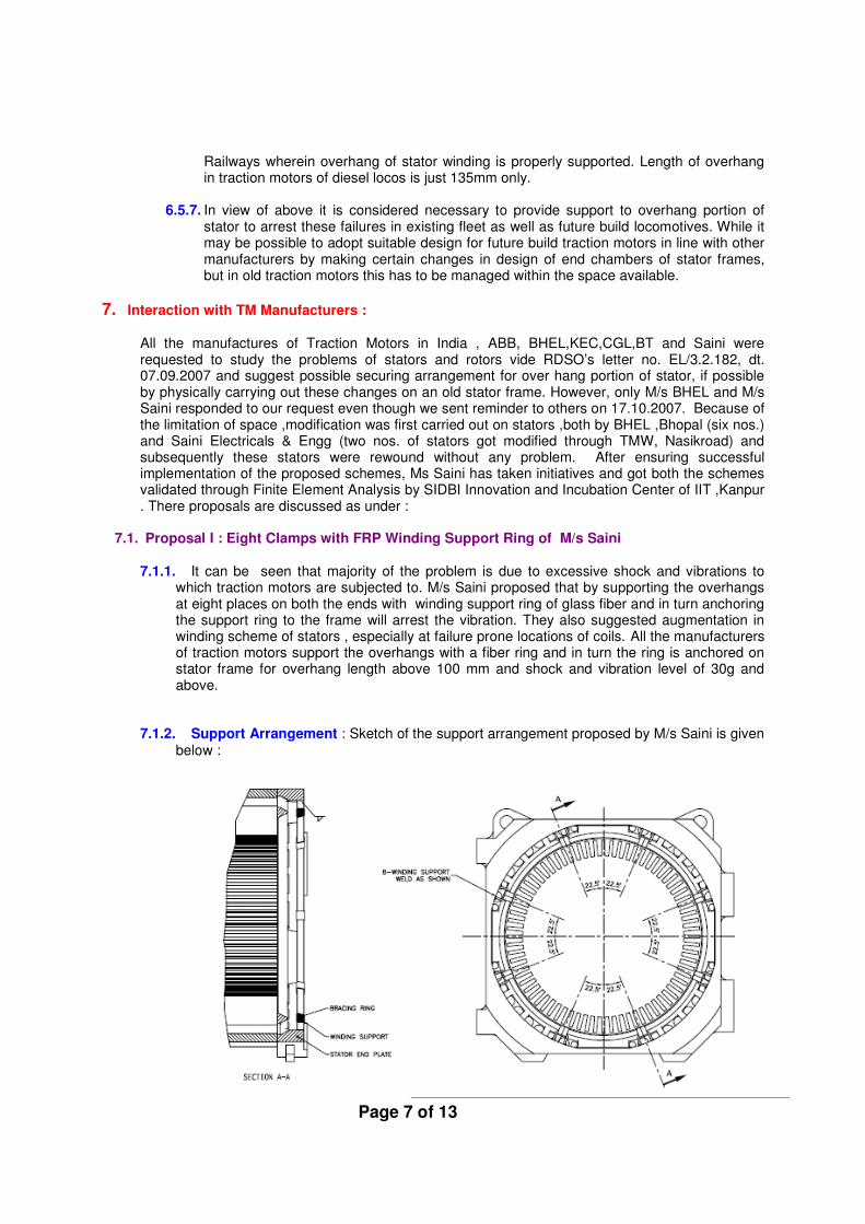
7.1. Proposal I : Eight Clamps with FRP Winding Support Ring of M/s Saini
7.1.1. It can be seen that majority of the problem is due to excessive shock and vibrations to
which traction motors are subjected to. M/s Saini proposed that by supporting the overhangs at eight places on both the ends with winding support ring of glass fiber and in turn anchoring the support ring to the frame will arrest the vibration. They also suggested augmentation in winding scheme of stators , especially at failure prone locations of coils. All the manufacturers of traction motors support the overhangs with a fiber ring and in turn the ring is anchored on stator frame for overhang length above 100 mm and shock and vibration level of 30g and above.
7.1.2. Support Arrangement : Sketch of the support arrangement proposed by M/s Saini is given below :

Page 8 of 13
Clamps Winding support ring
Proposed Support Arrangement for Stator Overhangs
All these eight clamps are to be bolted, each with M6 four bolts on stator chambers as shown above, which will be anchoring the winding support ring of FRP .Total 32 bolts nos. of M6 bolt, each designed for Proof Load Stress of 225 MPa is more than adequate to take care of maximum stress of 496 KPa load of each side of stator overhang at 90g of shock and vibration. It can also easily meet the pulsating load of 350 kg at 200-300 htz.
7.1.3. Augmentation of Insulation in Winding Scheme: To arrest failure near core ends &
shoulders of coils on both sides and knuckle of coil on NDE side following augmentations in winding arrangement are proposed. Measures discussed in following four paras,i.e 7.1.3.1 to 7.1.3.4 coupled with proper securing of over hangs as mentioned above will eliminate failure of stators.
7.1.3.1. Stator Winding Earthed/Flashed with Slots: Following action plan is proposed:
• The support arrangement discussed above is going to arrest the problem of grounding of insulation at slot ends.
• Apart from this, additional U-sections of Nomex (which has got insulation class of 220
0C) are proposed to be provided at slot ends in line with existing design of M/s
Siemens.
7.1.3.2. Inter turn short/flashed in Overhang: Following action plan is proposed to prevent failure on this account:
•••• Provision of securing arrangement between adjacent coils after inserting fibre glass epoxy pieces wrapped with nomex-felt between coils to fill up the available gap between coils to prevent relative movement between coils.
• Avoid crossing of two parallel copper conductors’ end one above other at knuckle portion, as space between two adjacent knuckles is very less , leading to rubbing of two coils knuckle which damages insulation. It should cross on each other in overhang portion away from knuckle to create sufficient space between knuckle & leads. Provision of extra layer of nomex in between is proposed.
• Avoid inter-turn failure at all bends as stresses developed on insulation during forming & shaping, interleaving of 2 mil X 25 mm Kapton tape in between turns at all 4 bends. The above scheme is already being followed by SIEMENS in traction motors of Diesel locos and there is no failure on account of stators.

Page 9 of 13
7.1.3.3. Failure at Brazed Joints at NDE Side : Following action plan is proposed -
•••• The proposed support arrangement of overhangs on NDE side is going to arrest the stresses on brazed joints.
•••• To provide tying between all series joints & interconnection (jumpers) with help of nomex-felt & glass tape to prevent movements.
•••• Since the space between two adjacent knuckles is very less ,crossing of two parallel copper conductors’ end one above other at knuckle portion, leads to rubbing of two coils knuckle and so damaging insulation. To prevent this rubbing two adjacent knuckles should cross on each other in overhang portion in such a way so that there is sufficient space between knuckle & lead. Provision of extra layer of nomex in between is proposed.
• To ensure controlled brazing at required temperature, it is proposed to resort to Induction brazing in place of existing gas brazing to customize low temperature high strength solder joint. Induction brazing is being followed by M/s SIEMENS and BHEL and even other leading manufacturers recommend for it.
7.1.3.4. Other failures on account of damage to Insulation :
• To avoid damaging insulation during forming of coils, use of former against the existing practice of using one pre-formed coil as the template for several times and finally using the template coil in stator is being proposed.
• Rotating curing is proposed immediately after VPI to ensure uniform distribution of resin followed by stationary curing, as resin will not ooze out during curing statically & bonding will be adequate.
•••• Existing practice of removing Kapton layer from brazing portion with gas should be replaced with solvent dipping as followed by SIEMENS.
7.2. Proposal II : Seven Clamps with FRP Winding Support Ring from M/s BHEL
7.2.1. BHEL has suggested only support arrangement at seven places.
• At four places, recesses are made by machining the stator chambers on either sides as shown below and then clamps are fixed with two bolts.
• At three other places, stators frames are drilled and L-section clamps are fixed with two bolts each from the top of the frame and threads in clamps.
• At the location, where connections for terminals are brought out on NDE side, no support has been provided in this scheme.
• All these clamps are anchoring the FRP winding support ring.
7.2.2. BHEL has not suggested any improvement in winding scheme to cater the problems of inter-turn short and grounding at slot ends.
7.3. Comparison of Two Schemes :
7.3.1. Finite Element analysis: To validate both the proposed schemes which are based on assumptions made that support arrangement of overhangs is going to eliminate stator overhang failure M/s Saini got FEA analysis carried out at SIDBI Innovation and Incubation Center at IIT, Kanpur for both the schemes on the request of RDSO. Like any other engineering system ,finite element analysis of stator frame has also three phases:

Page 10 of 13
7.3.1.1. Pre-processing Phase :
• Topological Description of Stator Designs: In the pre-processing stage, the stator frame along with windings has been represented by its geometrically 3 D model. The primary objective of the model is to realistically replicate the important parameters and features of the stator frames along with complete windings. 3-D models for existing stators and two proposed designs have been made on Solid Works and the same have been used by importing into an FEA environment. Once the finite element geometric models have been created, a meshing procedure is used to define and break up the model into small elements.
• Boundary Conditions or Environmental Factors : For carrying out the analysis two sets of boundary conditions were applied :
� Mechanical Shocks and Vibration :
BT carried out a trial to study vibration related problems on traction motors of WAG9 locomotives in Sept’2002 and measured shocks and vibration levels in various working condition of locomotives. The maximum values of accelerations recorded at various frequencies are taken as boundary conditions. The maximum level of shock and vibration has been taken as 89g for both static and dynamic loading condition for the analysis. Locations, where tri-axes accelerometers were provided for measurement are given in the trial report of BT. At these locations, these boundary conditions were applied.
� Thermal Conditions:
Maximum permissible temperature rise in traction motors is 2300C as at
this temperature pulsing of convertors stops and maximum flow of air through a traction motor is 1.2 m
3/sec at 1781 Pa. Since this temperature
is measured with temperature sensors embedded in stator frames, to take care of possibility of errors in measurement , for this analysis max. temperature in the stator, assumed is 300
0C. This boundary condition is
also used to validate if there is any thermal locking in stator windings with and without support arrangement.
7.3.1.2. Analysis ( computation of Solution) : The next stage of the FEA process is analysis. ABAQUS is the software used for FEA. A series of computational procedures are carried out involving applied forces as per boundary conditions discussed above and the properties of the elements. This structural analysis has provided stresses which are caused by applied boundary conditions such as mechanical vibrations and thermal loading.
7.3.1.3. Post-processing (visualization) : These results has been presented in graphical
tools within the FEA environment to view and to fully identify implications of the analysis.

Page 11 of 13
7.3.2. FEA Results : 7.3.2.1. FEA of Stators with original overhang arrangement , i.e without any support:
Analysis matches with the failure data. More stresses are coming on the winding overhangs near slot ends and its free portion . Red colour shows location of maximum stresses and dark blue location with least stress.
7.3.2.2. FEA of Stators with overhang support arrangement at eight locations as proposed by M/s SAINI in Proposal I: Because of uniform support at eight locations
which anchor winding ring , stresses on winding overhangs is eliminated.
Page 12 of 13
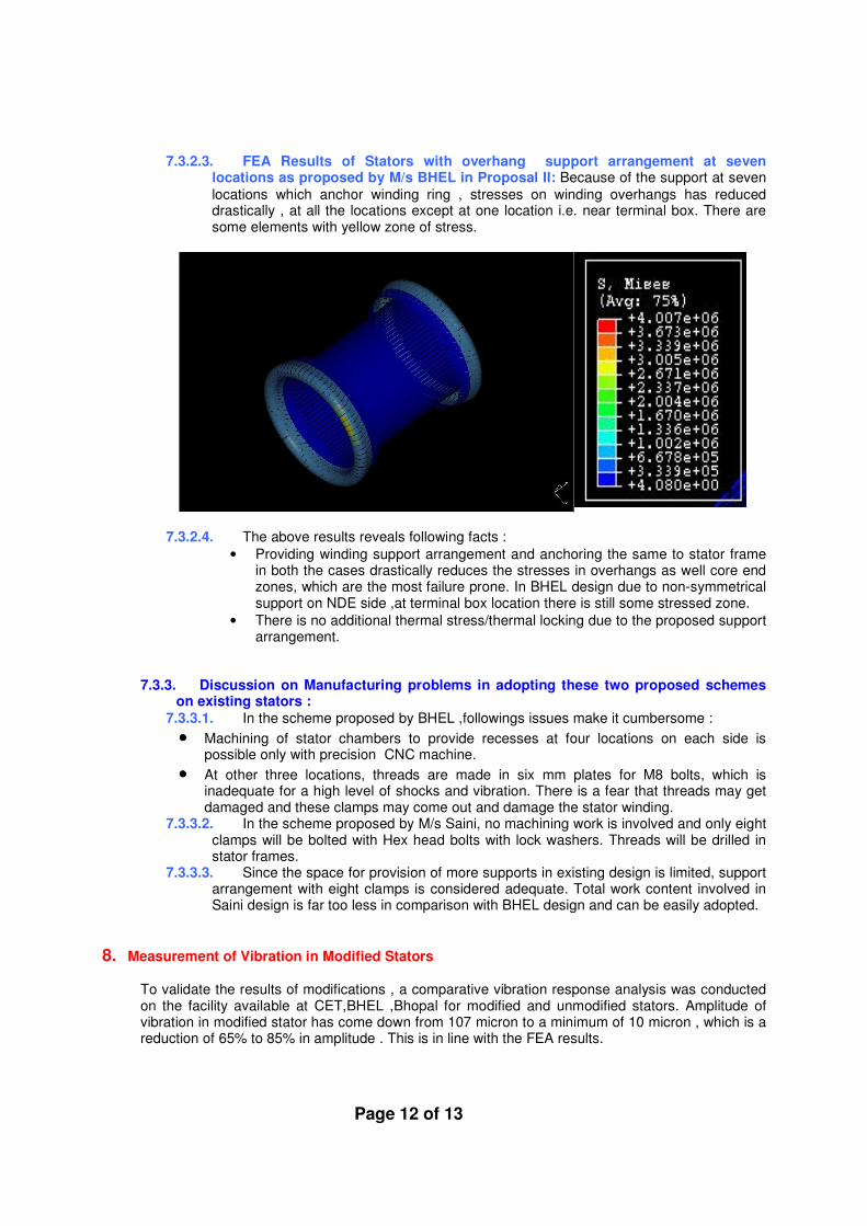
7.3.2.3. FEA Results of Stators with overhang support arrangement at seven locations as proposed by M/s BHEL in Proposal II: Because of the support at seven
locations which anchor winding ring , stresses on winding overhangs has reduced drastically , at all the locations except at one location i.e. near terminal box. There are some elements with yellow zone of stress.
7.3.2.4. The above results reveals following facts :
• Providing winding support arrangement and anchoring the same to stator frame in both the cases drastically reduces the stresses in overhangs as well core end zones, which are the most failure prone. In BHEL design due to non-symmetrical support on NDE side ,at terminal box location there is still some stressed zone.
• There is no additional thermal stress/thermal locking due to the proposed support arrangement.
7.3.3. Discussion on Manufacturing problems in adopting these two proposed schemes on existing stators :
7.3.3.1. In the scheme proposed by BHEL ,followings issues make it cumbersome :
•••• Machining of stator chambers to provide recesses at four locations on each side is possible only with precision CNC machine.
•••• At other three locations, threads are made in six mm plates for M8 bolts, which is inadequate for a high level of shocks and vibration. There is a fear that threads may get damaged and these clamps may come out and damage the stator winding.
7.3.3.2. In the scheme proposed by M/s Saini, no machining work is involved and only eight clamps will be bolted with Hex head bolts with lock washers. Threads will be drilled in stator frames.
7.3.3.3. Since the space for provision of more supports in existing design is limited, support arrangement with eight clamps is considered adequate. Total work content involved in Saini design is far too less in comparison with BHEL design and can be easily adopted.
8. Measurement of Vibration in Modified Stators
To validate the results of modifications , a comparative vibration response analysis was conducted on the facility available at CET,BHEL ,Bhopal for modified and unmodified stators. Amplitude of vibration in modified stator has come down from 107 micron to a minimum of 10 micron , which is a reduction of 65% to 85% in amplitude . This is in line with the FEA results.

Page 13 of 13
9. Conclusions
9.1. RDSO proposed two schemes for stator support arrangement which has been accepted by Railway Board . These are :
9.1.1. Immediate measures for re-winding of existing stators . So far 48 stators have been
modified with this scheme .
9.1.2. As a long term measures, it is proposed to change the design of clamp and bracing rings, so as to provide uniform and adequate support to over hang of stator coil as there is no constraint in adopting these proposals on new motors. CLW is going to cut in this scheme for future production.