RD BRAKING SYSTEM KEYNOTE SPEECH BY DATO’ SURET SINGH
269
Transcript of RD BRAKING SYSTEM KEYNOTE SPEECH BY DATO’ SURET SINGH


1
THE 23RD JASIC ASIA EXPERT MEETING RELATED TO VEHICLE BRAKING SYSTEM
KEYNOTE SPEECH BY DATO’ SURET SINGH
DIRECTOR GENERAL OF ROAD SAFETY DEPARTMENT, MALAYSIA
Good Morning and ohayogozaimas,
Mr. MASASI ISHIHARA – CHAIRMAN of BRAKES AND RUNNING GEAR SUBCOMMITTEE IN JASIC
Mr. MASAHARU OOSAWA - MEMBER of BRAKES AND RUNNING GEAR SUBCOMMITTEE IN JASIC Mr. MAKOTO MATSUO - MEMBER of BRAKES AND RUNNING GEAR SUBCOMMITTEE IN JASIC Mr. TORU IHARA - MEMBER of BRAKES AND RUNNING GEAR SUBCOMMITTEE IN JASIC Mr. YOSHIAKI NANBU - Secretariat of Expert Meeting and G/I Meeting in JASIC
Delegates from various Malaysian Government Departments,
Representatives of Motor Industries and Association in Malaysia.
All others present.
Ladies and Gentlemen,
I on behalf of the Ministry Of Transport Malaysia for being the host for
the 23rd JASIC Asia Expert Meeting with the theme Vehicle

2
Braking System ,would like to welcome all to this meeting and to the
foreign delegates and participants to have a nice stay in Malaysia.
Since Malaysia participated in the 1st JASIC meeting held in October
1998 in Tokyo, and their subsequent meetings, we became fully
aware of the importance to become a member and to participate in
the World Forum for Harmonization of Vehicle Regulations (WP29).
We also became fully aware of the advantages of global
harmonization of vehicle regulations. For that reason, on 4th April
2006, Malaysia has joined WP29 and signed 2 important agreements
which are 1958 and 1998 Agreements. This accession has results
many advantages to automotive industry players and also our
government.
For parts and components manufacturer the advantage is the
reduction in the development and production cost resulting from the
standardization of vehicle design specification. Another advantage is
the simplified certification procedures or process of each country,
which will expands the market and gives users a wider range of
choice.

3
The automobile and motorcycle manufacturers should comply with
the harmonized of vehicle regulations in order to overcome trade
barrier between nations.
In this context the parts and component manufacturers should also
strife to produce quality products in compliance with the regulations
for automobile and motorcycle manufactures and parts/components
replacement market.
The Motor Industry in Malaysia has grown very dramatically which
comprises of automobile and motorcycle manufacturers, motor
vehicle assemblers and automotive/motorcycle parts and
components manufacturers and fabrication of body works.
Malaysia has started to export local manufactured motor vehicles to
other countries and experiences various obstacle in compliance with
the regulations and certification process.
4
With the accession to the 1958/1998 Agreement in WP29 will
benefit the automotive and motorcycle industries and its product
acceptance by complying to the UN/ECE Regulations.
Ladies and Gentlemen,
The theme of this meeting “Vehicle Braking System” is the right
choice. Recently, there were news spreading all over the world
including Malaysia regarding the accidents occurred because of the
brakes failure especially public service vehicles.
As we all already well informed, braking system is part of the most
important system in a vehicle consist of combination of interacting
parts that work to slow the vehicle. It is very dangerous to road users
if the braking system not functioning correctly. To ensure the safety,
durability and performance of the vehicle braking system, WP29 has
come out with several regulations to control the brakes requirements
which are UNECE R13 : Brakes for M and N category , UNECE
R13H : Brakes for M1 category and UNECE R78 : Brakes for L
category vehicles.

5
Today, our partner from JAPAN will explains all technical
requirements about Vehicle Braking System under the WP29
requirements.
As for government, we will adopt these regulations as soon possible.
This expert meeting is one of our initiatives in order to establish
awareness among our industry players to get ready before they are
fully implemented in Malaysia.
For that reason, I hope we all can make all information beneficial and
apply them into our vehicle system in Malaysia.
Finally, I would like to thank all of you who are able to attend this The
23rd JASIC Asia Expert Meeting here today in Putrajaya.
Thank you

1
ECE Brake Regulation
Committee Chairman
Brakes and Running Gear Subcommittee
in JASIC
M.Ishihara

2
Table of Contents (1)
(1) GRRF Activities① Organization ② Objectives ③ List of Regulation
(2) General Aspect of Regulation① Principal ② Structure

3
Table of Contents (2)
(3)R13H① History & Current Status② Relevant Information③ Technical Requirement

4
(1) GRRF Activities
① Organization② Objectives of GRRF③ List of Regulation relevant to GRRF

5
① Organization of GRRF for Rule Making in UN
ECE RegulationECE (Geneva)
WP29
GRRF
ECE Reg. GTR**Global Technical Regulation
1998 agreement1958 agreement
: Brakes & Running Gear・’58/’98 Agreement Contracting Parties・Observer Countries・Non-Governmental Organization :OICA, CLEPA,ISO etc
UN

6
Covers Safety and Environment relevant to Brake and Running Gear
② Objectives of GRRF
SAFETY
ACTIVE SAFETY
PASSIVE SAFETYECE Reg.
ENVIROMENTCONSIDERATIONS
BRAKE
TYRE
COLLISION
EXHUST EMISSION
STEERING
TPMS
HEAD REST

7
③ List of Regulation relevant to GRRF
NO Contents
13 Commercial vehicle brake, EVSC13H Passenger vehicle brake, ESC, BAS30 Passenger vehicle tyre
54 Passenger vehicle tyre
55 Mechanical coupling
64 Temporary use spare tyre, TPMS
75 Motor cycle tyre
78 Motor cycle brake79 Steering equipment
89 Speed limiting device
90 Replacement brake Linings/Pad
117 Tyre noise, wet μ

8
(2) General Aspect of ECE Regulation
1. Principle of ECE Regulation
2. Structure of Regulation

9
(1) Social DemandRegulation shall have Social Necessity from Safety / Environment
(2) Minimum RequirementShall be reasonable considering Safety/Cost benefit.
(3) Performance RequirementShall be “Performance Requirement” as much as possible and minimize Design Requirement to maintain the design flexibility.
(4) Harmonized RegulationShall consider Global Harmonization.
1.Principle of ECE Regulation

10
2. Structure of Regulation
① Scope・Application of Vehicle Category( M1, M2, M3, N1, N2, N3, O1, O2, O3, L1, L2---etc )
② Definition・Define the Technical Terms used in the regulation
③ Application of Approval, Application・Certification Method, Certification Sheet
④ Specification・Technical Requirement
11
2. Structure of Regulation
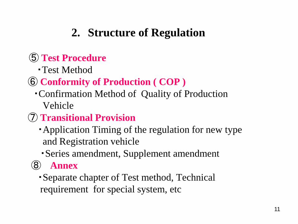
⑤ Test Procedure・Test Method
⑥ Conformity of Production ( COP )・Confirmation Method of Quality of Production
Vehicle⑦ Transitional Provision・Application Timing of the regulation for new typeand Registration vehicle・Series amendment, Supplement amendment
⑧ Annex・Separate chapter of Test method, Technical requirement for special system, etc

12
(3) R13HPassenger Vehicle Brake
① History & Current Status② Relevant Information③Technical Requirement

13
① History & Current status
1. History of Harmonization of PC BrakeRegulations
2. Country/Region who has introduced R13H

14
1. History of harmonization of PC brake regulations
Harmonized regulations for PC Brake R13H
1980~ 1990~ 2000~
・’80
Activity Started
at UN WP29/GRRF
・’92 Technical Consideration almost Finished ・’95 Detailed Consideration Completed
・98/5 R13H Adopted
ECE
(EU:71/320/EEC)
R1307/7
01/7 R13H
US FMVSS10595/5 FMVSS135
00/9
(Equivalent to Harmonized Regulation R13H)
Japan Safety Standard Article 12 New Safety Standard
Article 12 (R13H)94/4
96/1 04/1
98/11Safety STD Article 12(almost Equivalent to Harmonized Regulation R13H)

15
Summary Table of ECE R13H
・Secondary Performance in Various condition ・Smooth Phase inRBS⑰
・Control strategy ・Fail safe concept etcAnnex CEL⑯
・Compensation・Warning・Static performance ・Battery conditionEBS
Road surface:High μ, Low μ, Split μ, High μ → Low μ, Low μ→ High μ ・Utilized adhesion rate ε≧0.75 ・Vehicle behavior
ABS
≧1.5Dynamic parking
・20%(Without Trailer)・12%(With Trailer)Hand 400
Foot 500GVM
Static parking
⑫
ABS failure test⑪
LLVMGVM
Circuit failureEnergy failure
≦70≧6.4365~
500100
GVM
Dry
Engine off⑨
100HighNo rear lockbetween 0.15≦Z≦0.8
65~1000
65LowμWheel lock upSequence
⑧
・When 0.15≦Z≦0.8, f1>f2・When 0.2≦K≦0.8, f1 ≦ (Z+0.04)/0.7LLVMGVM
Adhesion
Equivalent toleft column α
≧ 70% &≦150% of achieved value①
Just after⑤Tested Value ①
100Fade
1.5kmAttain 3.0m/s250(4 times)DCooling
procedure
Equivalent toleft column α
≧60% of achieved value①&≧4.82Just after③Tested
Value ①100NFade condition
45secAttain 3.0m/s2
120 →60・15 times
GVM
Heating Procedure
S≦0.1V≧5.7680% Vmax≦160km/s2DHigh Speed
≦70≧6.4365~100℃65~500
100NLLVMGVM
Dry
Ordinary
Stopping Distance(m)
MFDD α(m/s2)
Temperature/Interval
Pedal force(N)
Initial speed(km/h)GearLoad Road
Performance RequirementTest ConditionNo
recovery
utilization
μ
⑩
performance
⑦
⑥
⑤
④
③
②
①
+0.0067V2
N
30
N65~
100℃ ≧2.44≧5.15
≦168
≦85
⑮
⑭
⑬

16
2. Country/region who introduced R13H
EU ○Norway ○Switzerland ○
Ukraine ○
Macedonia ○
Russian Federation ○
Belarus ○
Bosnia & Herzegovina ○
Azerubaijan ○
Serbia ○
Montenegro ○
Croatia ○
Turkey ○
Israel △
Tunisia ○
Republic of South Africa ○Africa
Europe
Middle East
Japan ○People's Republic of China △
Republic of Korea △
Hong Kong △
Taiwan △
Malaysia ○
Thailand (△)
Singapole △
USA △Canada △Argentina △Brazil △Chile △
Australia △
New Zealand △Oceania
Asia
America
○:Country/region who introduced R13H
△: Country who introduced equivalent regulation to R13H
RED: Contracting party of 1958 Agreement

17
② Relevant Information
1) Characteristics of Brake Regulation2) Basic Criteria

18
1) Characteristics of Brake Regulation
(1) Stopping Distance / MFDDA : Basic Requirement
(2) Vehicle Stability in braking
(1) Cold condition (Ordinarily condition)B : Test condition
(2) Hot condition (Fade)
C : New Technology Provision
(1) ABS (including EMC*) * Electromagnetic Compatibility(2) EBS (Electronically Controlled Braking system)(3) RBS (Regenerative Braking System)
(6) Safety Requirement for Complex Electronic Vehicle Control System(Annex CEL)
(3) Failure conditions (Secondary Brake)(4) Parking Brake(Static and Dynamic condition)
(4) BAS (Brake Assist System)(5) ESC (Electronic Vehicle Stability Control System)

19
2) Basic Criteria
(1) Stopping Distance
(2) Brake/Steering Operation
(3) Gear Shift Position in Braking
(4) Vehicle Stability

20
(1) Stopping Distance / MFDD

21
1. Definition of Stopping Distance
Time (sec)Brake On point
Braking DistanceStoppingDistance
MFDD
0.36 sec
Actual Deceleration
Dec
eler
atio
n (m
/sec
2 )
Vehi
cle
Velo
city
(m/s
ec)
Bra
king
D
ista
nce
(m)
Vehicle Velocity

22
2. Definition of MFDD (Mean Fully Developed Deceleration)
Vehi
cle
Velo
city
(m/s
2 )
Time (Sec)
V0
s m / )S - S (.
v - v = dMFDD be
ebm
222
9225
V b=0.8V0
Ve =0.1V0
Sb
Se
Bra
king
Dis
tanc
e (m
)
Vehicle Velocity
Braking DistanceS

23
3. Conversion of MFDD to Stopping Distance
V - S
V = d m10.0
0386.00
02
d
VVS = m
0386.010.0 02
0 +
dm= Mean Fully Developed Deceleration (m/sec2)
S=Stopping distance (m)
V0=Initial vehicle speed (km/h)

24
(2) Brake/Steering Operation(2) -1. Pedal Effort
(2) -2. Steering Correction is permitted under following condition
(2) -3. Wheel locking
Max. 500N, with no wheel locking
120 deg at first 2 sec 240 deg in total until vehicle stop
No wheel locking allowed over 15km/h vehicle speed
120deg
-120deg
-240deg
240deg
2sec
Stop
Brake start
OK
NG

25
(3) Gear Shift Position in Braking Gear shift position : Mainly Neutral position
(Drive position in some conditions)
(4) Vehicle Stability Vehicle has to be managed in braking within 3.5m-wide lane
Vehicle Slip Angle has to be less than 15 degrees
15 deg
3.5m
Braking starts
Stop

26
③Technical Requirement
1. Relevant Systems (1) Conventional system (2)ABS (Anti Lock Braking System)(3)EBS (Electronic Control Braking System)(4)RBS (Regenerative Braking System)(5)BAS(Brake Assist System)(6)ESC(Electronic Stability Control System)

27
(1) Conventional system without ABS(A) Dual circuit : Front-rear split Example
Booster
P-valve
Pedal
Master cylinder

28
(B) Dual circuit : X-diagonal split Example
Booster
P-valve
Pedal
Master cylinder
(1) Conventional system without ABS

29
(2) ABS ( In case of Front-Rear split )
Booster
ABS-Modulator
Pedal
Master cylinder
ECU
WSS(Wheel Speed Sensor)
・ Example

30
(3) EBS (Electronic Control Brake System)
EBS-Modulator
Pedal
Master cylinder
ECU
WSS(Wheel Speed Sensor)
・ Example

31
(4) RBS (Regenerative Braking System)
EBS-modulator
Pedal
Master cylinder
ECU
WSS
Mot
or
Battery
・ Example

(5)BAS (Brake Assist System)
Effective ness of BAS
Emergency Brake(Initial Vehicle Speed: 50 km/h)
W/O BAS W/ BAS
Stop
ping
Dis
tanc
e (m
)0
10
15
20
Expert Driver
5Brake
Torque
TimeWithout BAS
Judgment of Emergency Braking
Air
Stroke sensor
Solenoid
Assists braking force
ECU
With BASAssist
Experienced driver
・ Example
プレゼンター
プレゼンテーションのノート
緊急時のブレーキの踏み込み速度の違いは、ブレーキペダルの根元に取付けられたストロークセンサで検出します。 そして、ECUが緊急時の判定を行いますと、必要な制動力を助成する機構となっています。 ブレーキアシストがあれば、普通のドライバーでも熟練ドライバーに近い制動停止距離が実現します。

33
(6) ESC (Electronic Vehicle Stability Control System)・ Example
Brake Pressure Sensor
Wheel Speed Sensor(Each wheel)
Brake ECU
Steering Sensor
Brake Actuator
Yaw Rate & Acceleration Sensor
EFI/ECT ECU
On Board LAN
Braking Force Cntrol Unit
Driving Condition Detection Unit
Power Train Control Unit
Electronic Control Slot Valve

34
2. Function of brake equipment
The service braking system must make it possible to control the movement of the vehicle and to halt it safely, speedily and effectively, whatever its speed and load, on any up or down gradient. It must be possible to graduate this braking action. The driver must be able to achieve this braking action from his driving seat without removing his hands from the steering control.
5.1.2.1 Service braking system
5.1.2.2 Secondary braking systemThe secondary braking system must make it possible by application of the service brake control to halt the vehicle within a reasonable distance in the event of failure of the service braking system. It must be possible to graduate this braking action. The driver must be able to obtain this braking action from his driving seat without removing his hands from the steering control.For the purposes of these provisions it is assumed that not more than one failure of the service braking system can occur at one time
5.1.2.3 Parking braking system
The parking braking system must make it possible to hold the vehicle stationary on an up or down gradient even in the absence of the driver, the working parts being then held in the locked position by a purely mechanical device.The driver must be able to achieve this braking action from his driving seat.

35
2. Function of brake equipment5.2. Characteristics of braking systems
5.2.1. The set of braking systems with which a vehicle is equipped must satisfy the requirements laid down for service, secondary and parking braking systems.
5.2.2.1. there must be at least two controls, independent of each other and readily accessible to the driver from his normal driving position. Every brake control shall be designed such that it returns to the fully off position when released. This requirement shall not apply to a parking brake control when it is mechanically locked in an applied position.
5.2.2.2. The control of the service braking system must be independent of the control of the parking braking system;
5.2.2.3. The effectiveness of the linkage between the control of the service braking system and the different components of the transmission systems must not be liable to diminish after a certain period of use;
5.2.2.4. The parking braking system must be so designed that it can be actuated when the vehicle is in motion; This requirement may be met by the actuation of the vehicle’s service braking system, even partially, by means of an auxiliary control.

36
3. Type O Requirement
Prescribed value and other criteriaInitial braking speed
100km/h
Stopping distance 0.1V+0.0060v2 (70 m)
Mean fully developed deceleration
6.43m/s2
Force applied to control
65 to 500N
(1) In Cold condition with Engine Disconnected
Focusing point
- Stopping distance
- MFDD (Deceleration)
- Vehicle stability

37
(2) In Cold condition with Engine Connected
Focusing point
- Stopping distance
- MFDD (Deceleration)
- Vehicle stability
Prescribed values and other criteriaInitial braking speed 80%Vmax ≤ 160km/h
Stopping distance 0.1V+0.0067v2
Mean fully developed deceleration
5.76m/s2
Force applied to control
65 to 500N
3. Type O Requirement

38
Braking Force Distribution between Front and Rear axle is prescribed for non-ABS Vehicles
<Purpose> To assure vehicle stability To assure steerability
<Requirement (Calculation)>Earlier Rear wheel locking than front wheel is not allowed
for Stability.Too Early Front wheel locking is not allowed for
steerability.
4. Brake Force Distribution Requirement

39
(1) Formula
gP
EhzP
T= NT = f
⋅⋅⋅+1
1
1
11
gP
EhzP
T= NT = f
⋅⋅⋅−2
2
2
22
21:8.015.0 ffZ >≤≤
7.0/)04.0(:8.02.0 1 +≤≤≤ Zfk
<Definition>Z = Braking ratiok = Peak friction coefficient of
road surfacef1 = Adhesion utilization front axlef2 = Adhesion utilization rear axleT1 = Braking force at front axleT2 = Braking force at rear axleN1 = Front axle load in brakingN2 = Rear axle load in brakingP = Vehicle weightP1 = Static front axle loadP2 = Static rear axle loadh = Gravity heightE = Wheel baseg = Gravity acceleration
4. Brake Force Distribution Requirement
P1
P2
E
h
N1
N2
T1 T2
<Static> <Braking>

40
(2) Brake Force Distribution (Laden & Unladen)
0100200300400500600700800900
1000
0 500 1000 1500 2000
Front brake force T1(kgf)
Rear
bra
ke forc
e T
2(k
gf)
Actual Brake Force(Calculation)
Ideal Curve Laden
Ideal Curve Unladen
4. Brake Force Distribution Requirement

41
(3) Unladen Condition
4. Brake Force Distribution Requirement
0100200300400500600700800900
1000
0 500 1000 1500 2000
Front brake force T1 (kgf)
Rear
bra
ke f
orc
e T
2 (
kgf)
Rear lock prescribed line
Front lock Prescribed line
Actual Brake Force(Calculation)

42
(4) Laden Condition
4. Brake Force Distribution Requirement
0100200300400500600700800900
1000
0 500 1000 1500 2000
Front brake force T1 (kgf)
Rear
bra
ke f
orc
e T
2 (
kgf)
Front lock prescribed line
Rear lock prescribed line
Actual Brake Force(Calculation)

43
(5) Adhesion Curves (Unladen)
gP
EhzP
T= NT = f
⋅⋅⋅+1
1
1
11
gP
EhzP
T= NT = f
⋅⋅⋅−2
2
2
22
4. Brake Force Distribution Requirement
21:8.015.0 ffZ >≤≤
7.0/)04.0(:8.02.0 1 +≤≤≤ Zfk
f1 = Adhesion utilization front axle
f2 = Adhesion utilization rear axle
Adhesion Curve (Unladen)
0.0
0.1
0.2
0.3
0.4
0.5
0.6
0.7
0.8
0.0 0.2 0.4 0.6 0.8
f2
K=(Z+0.04)/0.7
Z (Braking ratio)
K (P
eak
fric
tion
coef
ficie
nt) f1
K=Z
0.15
44
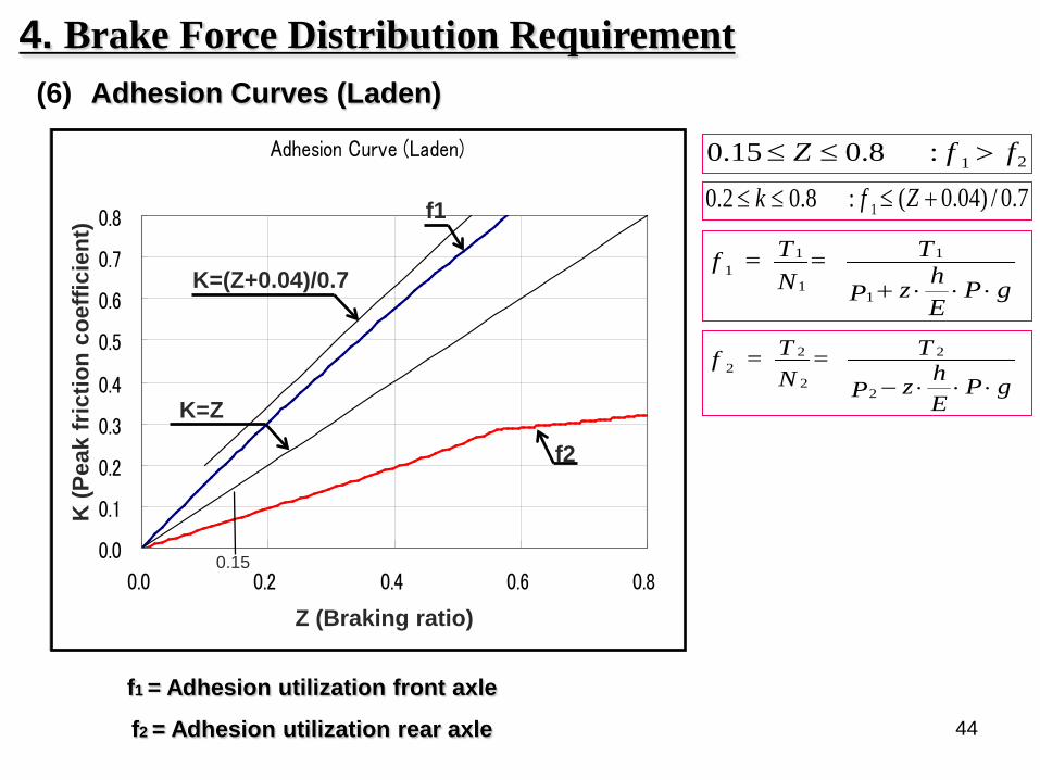
(6) Adhesion Curves (Laden)
4. Brake Force Distribution Requirement
gP
EhzP
T= NT = f
⋅⋅⋅+1
1
1
11
gP
EhzP
T= NT = f
⋅⋅⋅−2
2
2
22
21:8.015.0 ffZ >≤≤
7.0/)04.0(:8.02.0 1 +≤≤≤ Zfk
f1 = Adhesion utilization front axle
f2 = Adhesion utilization rear axle
Adhesion Curve (Laden)
0.0
0.1
0.2
0.3
0.4
0.5
0.6
0.7
0.8
0.0 0.2 0.4 0.6 0.8
f1
f2
K=(Z+0.04)/0.7
K=Z
Z (Braking ratio)
K (P
eak
fric
tion
coef
ficie
nt)
0.15

45
5. Un-braked Trailer Requirement(1) Requirement
(2) Calculation
Deceleration of Laden condition shall be more than 5.4 m/s.
PP
Pd = dRM
MMRM ++
dM+R = Calculated MFDD with Trailer
dM = MFDD on Type O test without Trailer
PM = Mass of vehicle
PR = Max mass of Trailer

46
6. Type I Requirement(1) Hot condition
Prescribed values and other criteriaInitial braking speed
100km/h
Stopping distance 75% of prescribed requirement of cold condition: 0.1V+0.0080v2 (90m)
60% requirement60% of the performance results of Type-0 test
Mean fully developed deceleration
75% requirement 4.82m/s2 or more
60% requirement60% of the performance results of Type-0 test
Force applied to control
Pedal force equivalent to that applied in Type-0 test
Focusing point
To check the brake performance stability after certain heating procedure
Heating up procedureVehicle speed:
120 -->60 km/hBrake application:
20 timesBraking interval:
45 sec

47
(2) Recovery performance
Focusing point
To check the brake recovery performance after certain cooling procedure.
Too high effectives checked, also has to be stable.
Cooling down procedureVehicle speed:
50 km/hBrake application:
4 timesBraking interval:
1.5 km
Prescribed values and other criteriaInitial braking speed 100km/h
Stopping distance 70% or more and 150% or less of the performance results of Type-0 test
Mean fully developed deceleration
Force applied to control
Pedal force equivalent to that used in Type-0 test
6. Type I Requirement
48
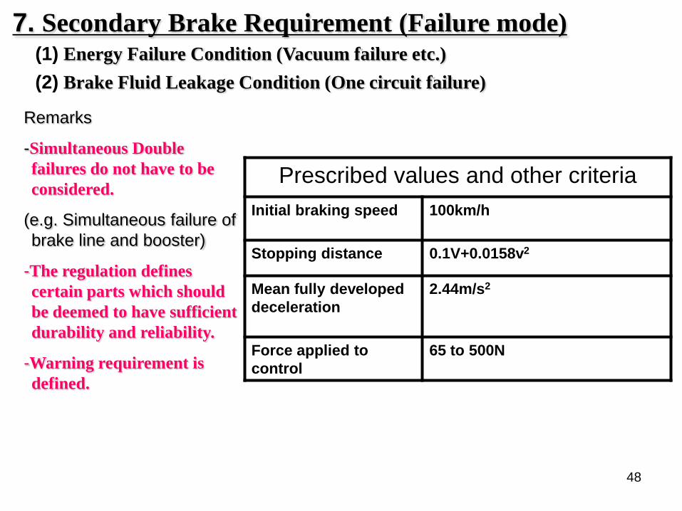
7. Secondary Brake Requirement (Failure mode)(1) Energy Failure Condition (Vacuum failure etc.)
Remarks
-Simultaneous Double failures do not have to be considered.
(e.g. Simultaneous failure of brake line and booster)
-The regulation defines certain parts which should be deemed to have sufficient durability and reliability.
-Warning requirement is defined.
Prescribed values and other criteriaInitial braking speed 100km/h
Stopping distance 0.1V+0.0158v2
Mean fully developed deceleration
2.44m/s2
Force applied to control
65 to 500N
(2) Brake Fluid Leakage Condition (One circuit failure)

49
7. Secondary Brake Requirement (Failure mode)
5.2.2.10 Certain parts, such as the pedal and its bearing, the master cylinder and its piston or pistons, the control valve, the linkage between the pedal and the master cylinder or the control valve, the brake cylinders and their pistons, and the lever-and-cam assemblies of brakes, shall not be regarded as liable to breakage if they are amply dimensioned, are readily accessible for maintenance, and exhibit safety features at least equal to those prescribed for other essential components (such as the steering linkage) of the vehicle. Any such part as aforesaid whose failure would make it impossible to brake the vehicle with a degree of effectiveness at least equal to that prescribed for secondary braking, must be made of metal or of a material with equivalent characteristics and must not undergo notable distortion in normal operation of the braking systems.
(3) Provision regarding durability of Brake parts

50
8. Warning signal
Fault warning NoteDifferential circuit pressure/Low fluid level RedPKB application (not failure) Red ControlBrake power unit failure/Low pressure Red
& acoustic**Only under the specified condition
Low energy level in electrically actuated braking systems
Red or acoustic
Electric control transmission failure resulting in only secondary performance
Red <6.43 m/s2
Electric control transmission -Low voltage resulting in only secondary performance
Red <6.43 m/s2
Break in the wiring within electric transmission or failure in the control of EPB
Red*& Yellow
*Flashing
(1) Summary table of Red warning signal : failure or defect defined in ECE13H

51
Fault warning NoteABS electrical or sensor failure Yellow
Lining wear-out Yellow When the Electric Pad Wear Indicator is installed
RBS distribution of braking among Axles failure
Yellow
EBS unsuitable compensation by the electric control transmission failure
Yellow
Electric control transmission failure Yellow ≧6.43 m/s2
Electric control transmission - Low voltage
Yellow ≧6.43 m/s2
(2) Summary table of Yellow warning signal: an electrically detected defect within the Vehicle brake equipment
8. Warning signal

52
9. Parking Brake Requirement
(1) Static parking brake performance
(2) Trailer towing capacity
Following item has to full fill regulation.
@ 20% slopeLever effort < 400NPedal effort < 500N
@ 12% slopeLever effort < 400NPedal effort < 500N

53
9. Parking Brake Requirement
Prescribed values and other criteria
Initial braking speed 30km/h
Mean fully developed deceleration
1.5m/s2
Deceleration immediately before stopping
Hand-operated: 400N or lessFoot-operated: 500N or less
(3) Dynamic parking brake performanceApplication of parking brake when the vehicle is in motion

54
(4) Electric Parking Brake System (EPB)
・Performance Requirement1.The Secondary performance for failure mode within the
electric control ・The Residual PKB performance
Static Performance for 8% slope2.Warning
・10 seconds red flashing indication etc
9. Parking Brake Requirement

55
10. Pad/Lining Wear Requirement5.2.11. Wear of the brakes must be capable of being easily taken up by
means of a system of automatic adjustment. In addition, the control and the components of the transmission and of the brakes must possess a reserve of travel ---------------.
5.2.11.1. Wear adjustment shall be automatic for the service brake. Automatic wear adjustment devices shall be such that after heating followed by cooling of the brakes, effective braking is still ensured. In particular the vehicle shall remain capable of normal running after the tests conducted in accordance with Annex3, paragraph 1.5 (Type-I test).
5.2.11.2. Checking the wear of the service brake friction components5.2.11.2.1. It shall be possible to easily assess this wear on service brake linings
from the outside or underside of the vehicle, without the removal of the wheels, by the provision of appropriate inspection holes or by some other means. This may be achieved by utilizingsimple standard workshop tools or common inspection equipment for vehicles.Alternatively, a sensing device per wheel (twin wheels are considered as a single wheel),which will warn the driver at his driving position when lining replacement is necessary,is acceptable.-------------
.

56
10. Pad/Lining Wear Requirement.5.2.11.2.2. Assessment of the wear condition of the friction surfaces of
brake discs or drums may only be performed by direct measurement of the actual component or examination of any brake disc or drum wear indicators, which may necessitate some level of disassembly.
Therefore, at the time of type approval, the vehicle manufacturer shall define the following:
(a) The method by which wear of the friction surfaces of drums and discs may beassessed, including the level of disassembly required and the tools and processrequired to achieve this.
(b) Information defining the maximum acceptable wear limit at the point at whichreplacement becomes necessary.
This information shall be made freely available, e.g. vehicle handbook or electronic data record.

57
11. Brake Fluid Requirement
5.2.12. In hydraulic-transmission braking systems, the filling ports of the fluid reservoirs must be readily accessible; in addition, the receptacles containing the reserve fluid must be so designed and constructed that the level of the reserve fluid can be easily checked without the receptacles having to be opened, and the minimum total reservoir capacity is equivalent to the fluid displacement resulting when all the wheel cylinders or caliper pistons serviced by the reservoirs move from a new lining, fully retracted position to a fully worn, fully applied position. If these latter conditions are not fulfilled, the red warning signalspecified in paragraph 5.2.21.1.1 below, shall draw the driver’s attention to any fall in the level of reserve fluid liable to cause a failure of the braking system.
5.2.13.The type of fluid to be used in hydraulic transmission braking systemsshall be identified by the symbol in accordance with Figure 1 or 2 of ISO Standard9128 - 1987 and the appropriate DOT marking (e.g. DOT3). The symbol and the markingmust be affixed in a visible position in indelible form within 100 mm of the filling portsof the fluid reservoirs; additional information may be provided by the manufacturer.

58
12. ABS Requirement
<Purpose>
① To check Adhesion Utilization and Vehicle Stability when ABS activated on *various road condition.
② Secondary performance for ABS failure and requirement for warning.
③ EMC (Electromagnetic Compatibility)
ABS system must not be affected by Electric / Magnetic field.
* Various road condition (next page for details)A : High µ road surfaceB : Low µ road surfaceC : µ split (different µ on left / right)D : µ jumping (High µ to Low µ, Low µ to High µ)

59
Various road condition
High µ
A : High µ road surface
Low µ
B : Low µ road surface
High µ
Low µ
C : µ split (different µ on left / right)
High µ Low µD : µ jumping (Low µ to High µ)
High µLow µD : µ jumping (High µ to Low µ)
12. ABS Requirement

60
(1) ABS Efficiency (condition A & B)ε=ΖAL/KM≧0.75
ΖAL: Maximum braking rate under ABS controlKM: Friction coefficient of road surface
(2) The Vehicle Stability and Wheel Lock
(Condition A,B,C,D)
* Various road conditionA : High µ road surfaceB : Low µ road surfaceC : µ split (different µ on left / right)D : µ jumping (High µ to low µ, low µ to High µ)
12. ABS Requirement

61
Prescribed values and other criteriaInitial braking speed 100km/h
Stopping distance 0.1V+0.075v2 (85m)
Mean fully developed deceleration
5.144 m/s2
(80% of Type O)Force applied to control
65 to 500N
Vehicle behavior The wheels shall not lock up at speeds exceeding 15km/h.The vehicle shall not deviate from a 3.5m-wide lane.The yaw angle shall not exceed 15 degrees.
(3) Secondary brake performance for ABS failure
(4) EMC (R10)The braking system shall not exhibit any malfunction caused by Electromagnetic field.
Remarks
-High µ condition
(Condition A)
12. ABS Requirement

62
13. Other Requirement

63
Performance Requirement・Additional requirements for failure within the electric
control transmission*The secondary brake performance under malfunction
of electric control transmission*Static service brake performance*Compensation*Charge-discharge balance with the use of electric
energy*Warning signal
1. EBS

64
2. RBS
This provision is mainly applied for Electric Vehicle and Hybrid vehicle
Performance requirement
① Secondly brake performance at system failure in various condition
② Smooth phase-in between conventional brake(Hydraulic) and Regenerative brake.

65
Performance Requirement
① Deceleration:aBAS ≧ aABS X 0.85at pedal force range of 0.5x to 0.7x FABS
②Activation:Manufacturer's Choice
Category B
Pedal force FD
ecel
erat
ion
aFABS0.5xFABS0.7xFABS
aABSaABSX0.85
W/O BASW/ BAS
ABSActivationaBAS
①Deceleration:ΔFEXT X 0.2≦ΔFBAS ≦ΔFEXT X
0.6②Activation:3.5m/s2 ≦aT*≦ 5.0m/s2
Category A
Dec
eler
atio
n a
Pedal force FFABS FABS,extrapolated
aABS
aT *
ΔFEXT
ΔFBAS
ABS Activation
W/ BAS
FT
Detect Emergency Braking by Pedal Effort and Activate BAS
W/O BAS
Detect Emergency Braking by Pedal Speed and Activate BAS
3. BAS

66
◆ Test Procedure & Judgment Criteria(Road surface μ≧0.9)
Test Procedure Judgment Criteria
Yaw Rate Ratio =Yr(t1)Yr(max) ≦0.35
Directional Stability
Responsiveness
270°≦ Maximum Steering Angle≦ 300°
Yaw Rate Ratio =Yr(t1.75)Yr(max) ≦0.20
and
Lateral Displacement of Steering Operation
=∫∫Lateral Accel ≧ 1.83 m / 1.52 m(GVW≦3.5t / GVW>
3.5t )
Time500ms
Time
St A
ngle
Yaw
Rat
e
1 s
Yr(max)
Yr(t1)
Late
ral A
ccel
∫∫Lateral Acceleration
4. ESCPerformance Requirement (Over Steer Intervention)
Dwell Sine Steering at 80km/h

67
3.Logic Diagram・Explanation of 2.・Under Steer Control Algorithm
1.System Diagram・System・Hard Wear Layout・Each Hard Wear Function
2.Basic Operational Characteristics・Capability of Braking Torque of each Wheel・Control of Propulsion Torque・Control during Acceleration/Deceleration・ ESC Active Vehicle Speed Range
◆ Technical Documentation
[
4. ESCPerformance Requirement(Under Steer Intervention)

68
5. Special Requirements on Safety Aspects of Complex Electronic Vehicle Control System (Annex CEL)
This regulation is applied to brake system with over-ride electronic control system.
(e.g. Hydraulic brake system with ABS, ACC,ESC, etc…)
Performance Requirement
The car manufacture should explain the system control strategy and fail safe concept etc. at type approval.
Secondary Brake performance has to be kept when the over-ride system failed.

69
Thank you very much for your attention

1
Braking Regulation No.1for Commercial Vehicle
Member of JASIC Brake CommitteeMasaharu Oosawa
Technical Requirement
Nov. 2010

2
• Introduction Section NumberVehicles ・・・・ 1Summary ・・・・ 2, 3Typical Brake systems for Commercial Vehicle ・・・・ 4, 5, 6
• Technical Requirement ・・・・ 7 ~ 31PerformanceStructure

3
1. Vehicles of R13
This Regulation applies to Vehicles of categories M2, M3, N and O.
M2 Bus GVM ≦5tM3 Bus 5t <GVMN1 Truck GVM ≦3.5tN2 Truck 3.5t <GVM ≦12tN3 Truck 12t <GVMO1 Trailer GVM ≦0.75tO2 Trailer 0.75t <GVM ≦3.5tO3 Trailer 3.5t <GVM ≦10tO4 Trailer 10t <GVM

4
2. Contents of R13Regulation 1 Scope
2 Definitions3 Application for approval4 Approval5 Specifications6 Tests7 Modification of vehicle type or braking system and extension of approval8 Conformity of production9 Penalties for non-conformity of production
10 Production definitely discontinued11 Names and addresses of Technical Services responsible for conducting approval tests, and of Administrative12 Transitional provisions
ANNEXES Annex1 Braking equipment, devices, methods and conditions not covered by this Regulation
Annex2Communication concerning the approval or extension or refusal or withdrawal of approval or production definitelydiscontinued of a vehicle type with regard to braking, pursuant to Regulation No.13
Annex3 Arrangements of approval marksAnnex4 Braking tests and performance of braking systemsAnnex5 Additional provisions applicable to certain vehicles as specified in the ADRAnnex6 Method of measuring the response time on vehicles equipped with compressed-air braking systemsAnnex7 Provisions relating to energy sources and energy storage devices (Energy accumulators)Annex8 Provisions relating to specific conditions for spring braking systemsAnnex9 Provisions relating to parking braking systems equipped with mechanical brake-cylinder locking device (LockAnnex10 Distribution of braking among the axles of vehicles and requirements for compatibility between towing vehiclesAnnex11 Cases in which Type-Ⅰand/or Type-Ⅱ(or Type-ⅡA) tests do not have to be carried outAnnex12 Conditions governing the testing of vehicles equipped with inertia (overrun) braking systemsAnnex13 Test requirements for vehicles fitted with anti-lock systemsAnnex14 Test conditions for trailers with electrical braking systemsAnnex15 Inertia dynamometer test method for brake liningsAnnex16 Compatibility between towing vehicles and trailers with respect to ISO11992 data communicationsAnnex17 Test procedure to assess the functional compatibility of vehicles equipped with electric control linesAnnex18 Special requirements to be applied to the safety aspectsof complex electronic vehicle control systemsAnnex19 Performance testing of trailer braking componentsAnnex20 Alternative procedure for the type approval of trailersAmmex21 Special requirements for vehicles equipped with a vehicle stability function
R13 is a Monster Regulation
5
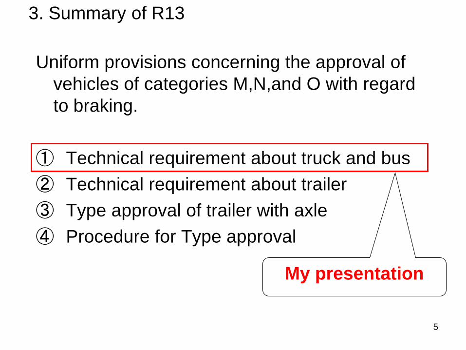
3. Summary of R13
Uniform provisions concerning the approval of vehicles of categories M,N,and O with regard to braking.
① Technical requirement about truck and bus② Technical requirement about trailer③ Type approval of trailer with axle④ Procedure for Type approval
My presentation

6
4. Typical service braking system
(1) For light trucksHydraulic braking system・dual-circuit braking system・hydraulic transmission・vacuum-assisted braking system・a pedal is the point where force is applied
by the driver’s muscular.
(2) For heavy duty trucksCompressed-air braking system・dual-circuit braking system・pneumatic transmission・full-power braking system・a pedal is a switch of compressed air
energy .
Master cylinder
Booster
Pedal
Pedal
Brake valve Air tank
Air dryerAir compressor
MPV

7
5. Typical parking braking system (1) For light trucks
① Wheel brake・mechanical transmission・muscular energy braking system・a lever is the point where force is applied
by the driver’s muscular.
② Transmission brake・mechanical transmission・muscular energy braking system・a lever is the point where force is applied
by the driver’s muscular. Engine
Transmission
leverParking cable
Axle
Transmission brake
lever
Parking cableWheel brake

8
A spring pushes the push rod when the compression air is exhausted from the parking brake valve, and it applies the brakes.
5. Typical parking braking system (2) For heavy duty trucksWheel brake・pneumatic transmission・full-power braking system・a lever is a switch of compressed air energy .・spring brakes are generally used for a
parking braking system.
Parking valve
Air tank
Air dryerAir compressor
MPV
Wheel brake
lever
Spring brake chamber
Parking Brake ValveSpring
Rod
Spring Brake Chamber Brake
Brake
Spring Parking Brake Valve
Usually a spring shrinks by the compression air from the parking brake valve.
【 reference 】 Typical Spring Brake
Brake Valve
Spring Brake Chamber
( Shrink ) ( Expand )

9
6. Typical endurance braking system
Engine
Transmission
② Engine retarder・mechanism in which an increased retarding effect is obtained by changing the valve timing to increase the internal resistance of the engine.
① Exhaust retarder・mechanism in which an increased retarding effect is obtained by blocking the flow of the exhaust gas to increase the internal resistance of the engine.
③ Hydraulic retarder・mechanism in which a retarding effect is obtained by using components links, usually to the driving wheels, and which pumps a fluid in a restricted circuit.
Axle
Exhaust pipe
Radiator
Endurance braking systems are generally used for trucks and buses, are not used for passenger vehicles.
プレゼンター
プレゼンテーションのノート
me

10
7. Function of brake equipment
5.1.2.1. Service braking system• The service braking system shall make it possible to control the movement of the vehicle and to halt it safely,
speedily and effectively, whatever its speed and load, on any up or down gradient. It shall be possible to graduate this braking action. The driver shall be able to achieve this braking action from his driving seat without removing his hands from the steering control.
5.1.2.2. Secondary braking system• The secondary braking system shall make it possible to halt the vehicle within a reasonable distance in the
event of failure of the service braking system. It shall be possible to graduate this braking action. The driver shall be able to obtain this braking action from his driving seat while keeping at least one hand on the steering control. For the purposes of these provisions it is assumed that not more than one failure of the service braking system can occur at one time.
5.1.2.3. Parking braking system• The parking braking system shall make it possible to hold the vehicle stationary on an up or down gradient
even in the absence of the driver, the working parts being then held in the locked position by a purely mechanical device. The driver shall be able to achieve this braking action from his driving seat, subject, in the case of a trailer, to the provisions of paragraph 5.2.2.10. of this Regulation. The trailer air brake and the parking braking system of the towing vehicle may be operated simultaneously provided that the driver is able to check, at any time, that the parking brake performance of the vehicle combination, obtained by the purely mechanical action of the parking braking system, is sufficient.
These are almost the same as R13H. There is the requirement of the test position used in parking brake examination.

11
7. Function of brake equipment5.2. Characteristics of braking systems
5.2.1.2.3.• IF the service braking system and the secondary braking system have the same control, the effectiveness of
the linkage between that control and the different components of the transmission systems shall not be liable to diminish after a certain period of use;
5.2.1.2.1.• There shall be at least two controls, independent of each other and readily accessible to the driver
from his normal driving position. For all categories of vehicles, except M2 and M3, every brake control (excluding an endurance braking system control) shall be designed such that it returns to the fully off position when released. This requirement shall not apply to a parking brake control (or that part of a combined control) when it is mechanically locked in an applied position;
5.2.1.1.• The set of braking systems with which a vehicle is equipped shall satisfy the requirements laid
down for service, secondary and parking braking systems.
5.2.1.2.2.• The control of the service braking system shall be independent of the control of the parking braking
system;
5.2.1.2.4.• If the service braking system and the secondary braking system have the same control, the parking braking
system shall be so designed that it can be actuated when the vehicle is in motion. This requirement shall not apply if the vehicle's service braking system can be actuated, even partially, by means of an auxiliary control;
These are almost the same as R13H.

12
7. Function of brake equipment5.1.4.2.• For the purpose of determining the in-use braking forces of each axle of the vehicle, with a compressed-air
braking system, air pressure test connections are required:
5.2.1.20.• In the case of a pneumatic service braking system comprising two or more independent sections, any
leakage between those sections at or downstream of the control shall be continuously vented to atmosphere.
5.2.1.14.• Without prejudice to the requirements of paragraph 5.1.2.3. of this Regulation, where an auxiliary source of
energy is essential to the functioning of a braking system, the reserve of energy shall be such as to ensure that, if the engine stops or in the event of a failure of the means by which the energy source is driven, the braking performance remains adequate to bring the vehicle to a halt in the prescribed conditions.
5.2.1.5.1.• In the event of failure in any part of the transmission of a braking system, the feed to the part not
affected by the failure shall continue to be ensured if required for the purpose of halting the vehicle with the degree of effectiveness prescribed for residual and/or secondary braking. This condition shall be met by means of devices which can be easily actuated when the vehicle is stationary, or by automatic means.
Annex8 3.1.• A spring braking system shall be so designed that, in the event of a failure in that system, it is still
possible to release the brakes. This may be achieved by the use of an auxiliary release device (pneumatic, mechanical, etc.).
R13H does not have these. These are some requirements of compressed-air braking systems.

13
7. Function of brake equipment5.2.1.17• If the trailer is of category O3 or O4, the service braking system shall be of the continuous or semi-
continuous type.
5.2.1.18.1.• When the towing vehicle's secondary braking system comes into action, there shall also be a
graduated braking action in the trailer;
5.1.3.8.• Shut-off devices which are not automatically actuated shall not be permitted. In the case of articulated
vehicle combinations, the flexible hoses and cables shall be a part of the power-driven vehicle. In all other cases, the flexible hoses and cables shall be a part of the trailer.
Annex8 2.3.1.• The feed circuit to the spring compression chamber shall either include an own energy reserve or shall be fed
from at least two independent energy reserves. The trailer supply line may be branched from this feed line under the condition that a pressure drop in the trailer supply line shall not be able to apply the spring brake actuators.
Annex8 2.7.• If a power-driven vehicle authorized to tow a trailer with a continuous or semi-continuous braking system is
fitted with a spring braking system, automatic application of the said system shall cause application of the trailer's brakes.
R13H does not have these.These are some requirements of compressed-air braking systems for towing vehicles .

14
8. Type O Requirement
(1) Cold condition with Engine Disconnected
The prescribed value and criteria are different in each vehicle category.
Focusing point
-Stopping distance
-MFDD (Deceleration)
-Vehicle stability
Category M2 M3 N1 N2 N3
Initial braking speed 60km/h 60km/h 80km/h 60km/h 60km/h
Stopping distance
Mean fullydevelopeddecelerationForce applied tocontrolVehicle behaviour without wheel lock
without deviation of the vehicle from its coursewithout abnormal vibration
Prescribed value and other criteria
5.0m/s2
70daN
Cold condition : the brake temperature is below 100℃.

15
8. Type O Requirement
(2) Cold condition with Engine Connected
Focusing point
-Stopping distance
-MFDD (Deceleration)
-Vehicle stability
Cold condition : the brake temperature is below 100℃.
The prescribed value and criteria are different in each vehicle category.
Category M2 M3 N1 N2 N3
100km/h 90km/h 120km/h 100km/h 90km/h
Stopping distance
Mean fullydevelopeddecelerationForce applied tocontrolVehicle behaviour without wheel lock
without deviation of the vehicle from its coursewithout abnormal vibration
4.0m/s2
70daN
Prescribed value and other criteria
Initial braking speed80%Vmax, but not exceeding the above speed

16
9. Brake Force Distribution Requirement
Braking Force Distribution between Front and Rear axle for non-ABS Vehicles
<Purpose>• To assure vehicle stability• To assure vehicle steerbility
<Requirement (Calculation)>• Earlier Rear wheel locking than front wheel is not allowed for Stability.• Too Early Front wheel locking is not allowed for Steerbility.
This is almost the same as R13H.The requirement apply to vehicle with more than two axles.

17
9. Brake Force Distribution Requirement(1) Formula
0.15≦Z≦0.8 : f1 > f20.2≦k≦0.8 : Z ≧0.1 + 0.85 ( k - 0.2 )
• i = axle index (i = 1, front axle; i = 2, second axle; etc.)• Pi = normal reaction of road surface on axle i under static conditions• Ni = normal reaction of road surface on axle i under braking• Ti = force exerted by the brakes on axle i under normal braking conditions on the road• fi = Ti/Ni, adhesion utilized by axle i • J = deceleration of vehicle• g = acceleration due to gravity: g = 9.81 m/s2
• z = braking rate of vehicle = J/g • P = mass of vehicle• h = height above ground of centre of gravity specified by the manufacturer and agreed by the Technical Services conducting the
approval test• E = wheelbase• k = theoretical coefficient of adhesion between tyre and road
.P.gEhz. + P
T = NT = f
1
1
1
11
.P.gEhz. - P
T = NT = f
2
2
2
22
In order to verify the requirements, the manufacturer shall provide the adhesion utilization curves for the front and rear axles calculated by the formula.

18
0.8
0.7
0.6
0.5
0.4
0.3
0.2
0.1
0.0 0.1 0.30.2 0.4 0.5 0.6 0.7 0.80.45
k = z
k = z + 0.05
k(f )i
z
( z + 0.07 ) 0.85k =
9. Brake Force Distribution Requirement(2) Adhesion Curves ;
0.15≦Z≦0.8 : f1 > f20.2≦k≦0.8 : Z ≧ 0.1 + 0.85 ( k - 0.2 )
vehicles of category N1 with a laden / unladen rear axle loading ratio not exceeding 1.5 or having a maximum mass of less than 2 tonnes
in the range of z values between 0.3 and 0.45, an inversion of the adhesion utilization curves is permitted provided that the adhesion utilization curve of the rear axle does not exceed by more than 0.05

19
0.8
0.7
0.6
0.5
0.4
0.3
0.2
0.1
0.0
k(f )i
0.1 0.30.2 0.4 0.5 0.6 0.7 0.8z
k = z
( z - 0.21 ) 0.50
k = z + 0.08
k = z - 0.08
0.15
( z + 0.07 ) 0.85
k =
k =
9. Brake Force Distribution Requirement(3) Adhesion Curves ;
0.15≦Z≦0.8 : f1 > f2
or
0.2≦k≦0.8 : Z ≧ 0.1 + 0.85 ( k - 0.2 )0.15≦Z≦0.3 : Z – 0.08 ≦ k≦ Z + 0.080.3≦Z≦0.5 : Z ≧ k + 0.08 【for f2】
0.5≦Z≦0.61 : Z ≧ 0.51k + 0.21 【for f2】
other vehicles of category N1
20
0.8
0.7
0.6
0.5
0.4
0.3
0.2
0.1
0.0
k(f )i
0.1 0.30.2 0.4 0.5 0.6 0.7 0.8z
k = z
( z - 0.02 ) 0.74
k = z + 0.08
k = z - 0.08
0.15
k =
k = ( z + 0.07 ) 0.85
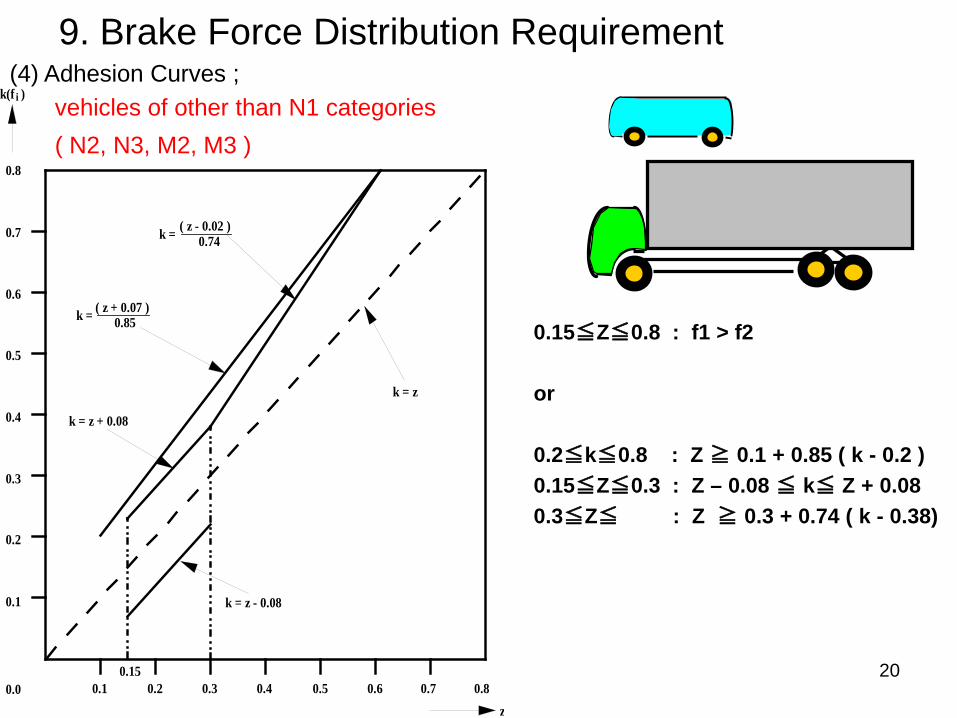
9. Brake Force Distribution Requirement(4) Adhesion Curves ;
0.15≦Z≦0.8 : f1 > f2
or
0.2≦k≦0.8 : Z ≧ 0.1 + 0.85 ( k - 0.2 )0.15≦Z≦0.3 : Z – 0.08 ≦ k≦ Z + 0.080.3≦Z≦ : Z ≧ 0.3 + 0.74 ( k - 0.38)
vehicles of other than N1 categories( N2, N3, M2, M3 )

21
10. Compatibility between towing vehicles and trailers
Requirements for compatibility between towing vehicles and trailers without ABS
<Purpose>• To assure combination-vehicle stability• To assure combination-vehicle steerbility
Wheel Lock of trailer Wheel Lock of tractor
Progress direction Progress direction
By the wheel lock of the trailer, the trailer swing occurs. this is very dangerous.
By the wheel lock of the tractor, the jackknife occurs. this is very dangerous.

22
10. Compatibility between towing vehicles and trailers
< Requirement ( Calculation ) >• Prescribed deceleration of combination-vehicle appear depending on pressure at
coupling head of control line.
In brakes, braking power is not added to thecoupler that connects a tractor and a trailer. As a result, the combination-vehicle stability is good.
If the deceleration of the trailer is the same as the deceleration of the tractor, the stability of the combination-vehicle is good.
R13H does not have this.
tractor
tractor trailer
trailer

23
10. Compatibility between towing vehicles and trailers
(1) Definition
・Kc = correction factor: semi-trailer laden・ Kv = correction factor: semi-trailer unladen・TM = sum of braking forces at the periphery of all wheels of towing vehicles for trailers・ PM = total normal static reaction of road surface on wheels of towing vehicles for trailers ・pm = pressure at coupling head of control line・TR = sum of braking forces at periphery of all wheels of trailer・PR = total normal static reaction of road surface on all wheels of trailer ・ PRmax = value of PR at maximum mass of trailer・ER = distance between king-pin and centre of axle or axles of semi-trailer・hR = height above ground of centre of gravity of semi-trailer specified by the manufacturer and agreed by
the technical services conducting the approval test

24
10. Compatibility between towing vehicles and trailers
(2) Braking rate TM/PM and pressure pm ; Towing vehicles other than tractors for semi-trailers
In the case of a power-driven vehicle authorized to tow trailers of category O3 or O4 fitted with a compressed air braking system, the permissible relationship between the braking rate TM/PM and the pressure pm shall lie within the areas shown on diagram 2 of this annex for all pressures between 20 and 750 kPa.
diagram 2

25
10. Compatibility between towing vehicles and trailers
(3) Braking rate TM/PM and pressure pm ; Tractors for semi-trailers
In the case of a vehicle fitted with a compressed air braking system, the permissible relationship between the braking rate TM/PM and the pressure pm shall be within the areas shown on diagram 3 of this annex for all pressures between 20 and 750 kPa.
diagram 3

26
(1) Requirement
Deceleration of Laden condition shall be more than 5.0 m/s2
11. Un-Braked Trailer Requirement
(2) Calculation
dM+R = calculated MFDD with trailer m/s2
dM = MFDD on TypeO test without Trailer PM = Mass of vehicle PR = Max mass of trailer
This is almost the same as R13H.

27
M2
N1
M3, N2, N3
Conditions of heating procedure
unmber of brakeapplications
55
55
time of brakinginterval ( sec )
80% Vmax ≦ 100
60
15
15
20
Category ofvehicles
1/2 V1
1/2 V1
1/2 V1
80% Vmax ≦ 120
80% Vmax ≦ 60
V1 : initial speed( km/h )
V2 : speed at end( km/h )
12. TypeⅠ Requirement
Category M2 M3 N1 N2 N3
Initial braking speed 60km/h 60km/h 80km/h 60km/h 60km/h
Force applied tocontrol
Stopping distance
Mean fully developeddeceleration
80% of Type-O requirement of cold condition
60% of Type-O test result of MFDD
60% of Type-O test result of stopping distance
80% requirement 5.0m/s2
Pedal force equivalent to that applied in Type-O test
Prescribed value and other criteria
(1) With repeated braking
(2) Hot condition
Focusing point
Check brake performance after certain heating procedure
(3) Free running testVerify that the vehicle is capable of free running after brake temperatures become to be cold.
① wheels are running freely. or
② the temperatures shall not exceed a drum / disc temperature increase of 80℃ while driving at 60km/h.
This is almost the same as R13H.The prescribed value and criteria are different from R13H.R13 does not have the recovery performance. but, R13 has the free running test.

28
13. Secondary Brake Requirement (Failure mode)
(1) Energy Failure Condition① In Case of Vacuum-assisted braking system
・Vacuum failure
② In Case of Full-power braking system
・Failure of energy sources ( 5 times of braking after warning without energy supply )
・Capacity of energy reservoirs (9 times of braking without energy supply)
・Capacity of down-circuit energy reservoirs ( 5times of braking in up-circuit failure)
(2) Brake Air or Fluid Leakage Condition ( One circuit failure)・Rear circuit failure
・Front circuit failure
(3) Failure Condition Of Braking Distribution System ( L.S.P.V failure)

29
13. Secondary Brake Requirement (Failure mode)
Remarks
- Simultaneous double failures shall not be assumed.
- The regulation defines certain parts which should be deemed to have sufficient durability and reliability.
- Warning requirement is defined.
Category M2 M3 N1 N2 N3
Initial braking speed 60km/h 60km/h 70km/h 50km/h 40km/h
Stopping distance
Mean fullydevelopeddeceleration
by footby hand
Force applied tocontrol
0.15v+(2V2/115)0.15v+(2V
2/130)
2.5m/s2
2.2m/s2
70daN60daN
Prescribed value and other criteria
This is almost the same as R13H. The prescribed value and criteria are different in each vehicle category.

30
13. Secondary Brake Requirement (Failure mode)
(4) Provision regarding durability of Brake parts
5.2.1.2.8.certain parts, such as the pedal and its bearing, the master cylinder and its piston or pistons (hydraulic systems), the control valve (hydraulic and/or pneumatic systems), the linkage between the pedal and the master cylinder or the control valve, the brake cylinders and their pistons (hydraulic and/or pneumatic systems), and the lever-and-cam assemblies of brakes, shall not be regarded as liable to breakage if they are amply dimensioned, are readily accessible for maintenance, and exhibit safety features at least equal to those prescribed for other essential components (such as the steering linkage) of the vehicle. Any such part as aforesaid whose failure would make it impossible to brake the vehicle with a degree of effectiveness at least equal to that prescribed for secondary braking shall be made of metal or of a material with equivalent characteristics and shall not undergo notable distortion in normal operation of the braking systems.
This is almost the same as R13H.

31
Stopping distance Stopping distanceLaden ( m ) Unladen ( m )
M2 60 1.5 0.15v+(100/25)×(v2/130) 1.3
M3 60 1.5 0.15v+(100/30)×(v2/130) 1.5
N1 70 1.3 1.1
N2 50 1.3 1.1
N3 40 1.3 0.15v+(100/30)×(v2/115) 1.3
MFDD( m/s2 )
MFDD( m/s2 )
0.15v+(100/25)×(v2/115)
0.15v+(100/30)×(v2/115)
0.15v+(100/30)×(v2/130)
Category ofvehicles
Prescribed value and other criteriaV
( km/h )
14. Residual Brake Requirement (after transmission Failure mode)
・ Residual brake requirement shall be required when secondary brake requirement of one circuit failure is met by parking braking system.
( It is almost a case in a heavy-duty vehicle with multi axles. )
・ Residual brake requirement is the requirement of a service braking systemafter transmission failure mode.
R13H does not have this.

32
15. Warning signal(1) Summary table of Red warning signal
Fault Warning Note
Differential circuit pressure / Low fluid level Red
PKB application ( not failure ) RedBrake power unit failure / Low pressure Red & acousticLow energy level in electrically actuated braking Red or acousticElectric control transmission failure on EBS resulting inonly secondary performance
Red
Low voltage of Electric control transmission resultingin only secondary performance on EBS
Red
Break in the wiring within electric transmission offailure in the control of EPB
Red & Yellow
Low pressure in the line feeding energy to the springcompression chamber
Red or acoustic
Trailer provide corresponding failure informationRed & Yellow of trailer,or Red of trailer
Failure within electric control transmission of trailer orfailure of energy supply available from ISO 7638resulting in only secondary performance
Red & Yellow of trailer,or Red of trailer
Low energy level in electrically actuated brakingsystems in case of trailer
Red & Yellow of trailer,or Red of trailer
Low voltage of electric control transmission on EBS incase of trailer connected tractor
Red & Yellow of trailer,or Red of trailer

33
15. Warning signal(2) Summary table of Yellow warning signal
Fault Warning NoteABS electrical or sensor failure YellowPad wear YellowBraking force distribution failure among axles on RBS YellowEBS excessive compensation on electric controltransmission ( failure /not failure )
Yellow
Electric control transmission failure on EBS YellowLow voltage of electric control transmission on EBS YellowCoupling force control failure YellowCoupling force control excessive compensation ( notfailure )
Yellow
ABS electrical failure in case of trailer Yellow of trailerEBS excessive compensation on electric controltransmission in case of trailer ( failure /not failure )
Yellow of trailer
Failure within electric control transmission of trailer orfailure of energy supply available from ISO 7638
Yellow of trailer
Electric control transmission failure on EVSC in caseof trailer
Yellow of trailer under review
Low voltage of electric control transmission on EBS incase of trailer not connected tractor
Yellow of trailer
EVSC is in intervention mode Yellow of ESCflashing onand off
EVSC failure Yellow of ESC on a light
EVSC of trailer is in intervention mode Yellow of ESCflashing onand off
EVSC OFF Yellow of ESC OFF

34
16. Stop lamps
Summary table of Stop lamps
R13 prescribes generation of a braking signal to illuminate stop lamps
Service Braking System
Endurance with EBSBraking ( EBS : Electronic Braking System ) System
without EBS
Engine Braking
AutomaticallyCommanded Braking
Selective Braking( activation of part of the service braking system )
Regenerative Braking System
0.7 1.0 1.3
Decelaration (m/s2)
may
may
shall
shall not
shall
shall
shall not
shall not
may

35
Category
V(km/h)
Stopping distance (m)MFDD(m/s2)
M3 60 0.15v+(1.33v2/130) 3.75
N3 60 0.15v+(1.33v2/115) 3.3
Prescribed value and other criteria
17. Type-Ⅱtest (downhill behaviour test)
Category : M3, N3
Purpose :
Vehicle can be driven at 30km/h on 6% down slope for 6km by service braking system and endurance braking system.
Purpose of Type - Ⅱtest
Actual Type -Ⅱtest
① Towing test
② Hot performance test of service braking system after towing test
Test vehicle( laden )
6% down - gradient6km
Vehicle Speed = 30km/h
Test vehicle( laden )
towing vehicle
Energy is equivalent
Hot performance of service braking system after towing test
Test vehicle
Test of service braking system
R13H does not have this.

36
Category :
Purpose :
Vehicle can be driven at 30km/h on 7% down slope for 6km by only endurance braking system.
( Not use service braking system )
Purpose of Type - ⅡA test
Actual Type -ⅡA test
Towing test
Test vehicle( laden )
towing vehicle
Energy is equivalent
18. Type-ⅡA test (endurance braking performance)
Test vehicle( laden )
6km
7% down - gradient
Vehicle Speed = 30km/h
① Interurban motor coaches and long distance motor coaches of M3
② N3 which are authorized to tow a trailer of O4
③ Certain vehicles subject to ADR
ADR : European Agreement concerning the International Carriage of Dangerous Goods by Road
R13H does not have this.

37
19. Parking Brake Requirement
(1) Static parking brake performance
laden laden
laden
laden laden
laden
(2) Trailer towing capacity
18% slope
Hand lever force ≦60daN
Foot pedal force ≦70daN
12% slope
Hand lever force ≦60daN
Foot pedal force ≦70daN
Parking braking system of towing vehicle can hold combination of vehicles on 12% slope
Focusing point :

38
19. Parking Brake Requirement
(3) Dynamic parking brake performanceApplication of parking brake when the vehicle is in motion
Initial braking speed 30km/h
Mean fully developeddeceleration 1.5m/s
2
Hand - operated : 60daN or LessFoot - operated : 70daN or Less
Applied force
Prescribed value
)) ) ) )
laden
Test of parking braking system

39
19. Parking Brake Requirement
(4) Electric Parking Brake System
1. The Secondary performance for failure mode within the electric control.
・ The Residual PKB performance Static Performance for 8% slope
2. Warning
・10seconds red flashing indication etc.
This is almost the same as R13H.

40
20. Response Time Requirement ( not failure )
< Purpose >
・To assure the response performance of the compressed-air braking system in normalcy.
< Requirement >
・It prescribes time when the air pressure rises after having pushed a brake pedal.
R13H does not have this.
① push a brake pedal
② brakes air pressure rises
③ brake is actuated
To check the response time for air braking system in normalcy

41
20. Response Time Requirement ( not failure )■ Scope : vehicles equipped with compressed – air braking systems
■ Initial air pressure : governor cut in
■ LSPV : Laden condition
■ Dummy air tank for tractor :
① a pipe 2.5m long with an internal diameter of 13mm joined to the coupling head of the control line
② a tank 385cm2 volume or a pipe 2.5m long with an internal diameter of 13mm joined to the coupling head of the supply line
■ Pedal operation speed : 0.2sec which is a time to reach the full stroke
■ Requirement of response time :
Truck & Tractor, 75%Pmax ≦0.6 sec , at the cylinder pressure of the least favourably placed brake
Tractor, 75%Pmax≦0.4sec, 10%Pmax≦0.2sec, at dummy pipe pressure on the control line
full stroke
peda
lst
roke
time
press
ure
pressure
75% Pmax,truck, tractor ≦0.6sec ( brake cylinder )tractor ≦0.4sec ( dummy pipe of the control line )
10% Pmax, tractor ≦0.2sec ( dummy pipe of the control line )
0.2sec
time
R13H does not have this.

42
21. Exhaust Response Time Requirement ( failure mode )
R13H does not have this.
< Purpose >
・To assure the exhaust response performance of the compressed-air braking system when the control line at the coupling head of the combination-vehicle is broken.
< Requirement >
・ It prescribes time when the air pressure of the supply line drops after having pushed a brake pedal.
To check the exhaust response time for air braking system of the combination-vehicle at the time of trouble.
×② push a brake pedal
③ air is exhausted
⑥ brake of trailer is actuated
① control line at the coupling head is broken
④ air pressure of the supply lines at the coupling head drops⑤ relay emergency valve of trailer is actuated
tractortrailer

43
21. Exhaust Response Time Requirement ( failure mode )■ Scope : vehicles equipped with compressed – air braking systems, and authorized to tow trailers of O3 or O4
■ Dummy air tank for tractor : a pipe 2.5m long with an internal diameter of 13mm joined to the coupling head of the supply line
■ Air pressure : failure of the control line at the coupling head
■ Pedal operation speed : 0.2sec which is a time to reach the full stroke
■ Requirement of response time :
≦2sec, at 150kPa of dummy pipe pressure on the supply line
full stroke
peda
lst
roke
time
press
ure
pressure of the trailer supply line
at 150kPa of dummypipe on the supply line,
0.2sec
150kPa
time ≦ 2sec
R13H does not have this.

44
22. Air Compressor Actuating Time Requirement
R13H does not have this.
< Purpose >
・To assure the filling performance of the air compressor.
< Requirement >
・ It prescribes time till maximizing air tank pressure from zero by actuating the air compressor .

45
time
press
ure
pressure
t1
t2
p1
p2
■ Scope : vehicles equipped with compressed – air braking systems
■ Initial air pressure : 0
■ Dummy air tank for tractor : air tank volume = 20R/P, R=Maximum mass of the axles of the trailer, P=Maximum pressure on the supply line
■ Compressor speed : Maximum engine speed
■ Requirement of air compressor actuating time :
① Auxiliary tank capacity < 20% of the total air brake tank,
Truck t1 ≦180sec, t2 ≦360sec ( accessory line is closed )
Tractor t1 ≦360sec, t2 ≦540sec ( accessory line is closed )
② Auxiliary tank capacity ≧ 20% of the total air brake tank,
Additional requirement
Truck t3 ≦ 480sec ( accessory line is normal )
Tractor t3 ≦ 660sec ( accessory line is normal )
■ Definition :
t1 : time from 0 to p1 in air brake tank
t2 : time from 0 to p2 in air brake tank
t3 : time from 0 to p2 in the least-favoured tank
p1 : 0.65 p2
p2 : governor cut out pressure ( maximum pressure )
22. Air Compressor Actuating Time Requirement
R13H does not have this.
governor cut out pressure
(0.65p2)

46
23. Spring Brake Requirement
Point of Annex8 2.3.2. • Spring brakes can be released at least one time after accessory line failure• Measurement pressure in the spring brake chambers ≧ Pressure to release the spring brakes
Point of Annex8 2.3.3. • During re- changing of the braking system from zero pressure, spring brakes shall work till the
secondary braking performance is satisfied.
Point of Annex8 2.3.4.• Once applied, spring brakes shall not release till the residual braking performance is satisfied.
Point of Annex8 2.4.• Spring brakes can be applied and released at least three times if the initial pressure in the spring
brake chamber is maximum.
Point of Annex8 2.5.• Pressure in the spring brake chamber when the springs begin to actuate the brakes, shall not be
greater than 80 % of the governor cut in pressure.
R13H does not have this.

47
24. Pad / Lining Wear Requirement
5.2.1.11.1.• Wear adjustment shall be automatic for the service brakes. However, the fitting of automatic brake
adjustment devices is optional for off-road vehicles of categories N2 and N3 and for the rear brakes of vehicles of category N1. Brakes equipped with automatic brake adjustment devices shall, after heating followed by cooling, be capable of free running as defined in paragraph 1.5.4. of Annex 4 following the Type-I test also defined in that annex.
5.2.1.11.• Wear of the brakes shall be capable of being easily taken up by means of a system of manual or
automatic adjustment. In addition, the control and the components of the transmission and of the brakes shall possess a reserve of travel and, if necessary, suitable means of compensation such that, when the brakes become heated, or the brake linings have reached a certain degree of wear, effective braking is ensured without immediate adjustment being necessary.
5.2.1.11.2.1.• It shall be possible to easily assess this wear on service brake linings from the outside or underside
of the vehicle, without the removal of the wheels, by the provision of appropriate inspection holes or by some other means. This may be achieved by utilizing simple standard workshop tools or common inspection equipment for vehicles. Alternatively, a sensing device per wheel (twin wheels are considered as a single wheel), which will warn the driver at his driving position when lining replacement is necessary, is acceptable. In the case of an optical warning, the yellow warning signal specified in paragraph 5.2.1.29.1.2. below may be used.
These are almost the same as R13H.

48
25. Disc / Drum Wear Requirement
5.2.1.11.2.2.• Assessment of the wear condition of the friction surfaces of brake discs or drums may only be
performed by direct measurement of the actual component or examination of any brake disc or drum wear indicators, which may necessitate some level of disassembly. Therefore, at the time of type approval, the vehicle manufacturer shall define the following: (a) The method by which wear of the friction surfaces of drums and discs may be assessed, including the level of disassembly required and the tools and process required to achieve this. (b) Information defining the maximum acceptable wear limit at the point at which replacement becomes necessary. This information shall be made freely available, e.g. vehicle handbook or electronic data record.
This is almost the same as R13H.
49
26. Brake Fluid Requirement
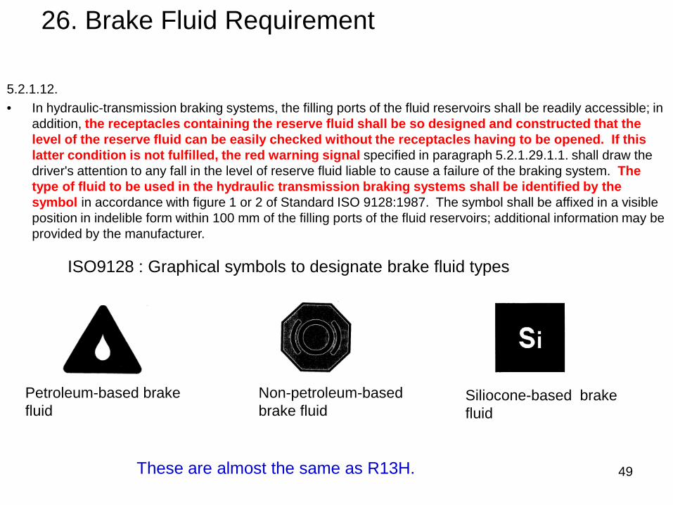
5.2.1.12.• In hydraulic-transmission braking systems, the filling ports of the fluid reservoirs shall be readily accessible; in
addition, the receptacles containing the reserve fluid shall be so designed and constructed that the level of the reserve fluid can be easily checked without the receptacles having to be opened. If this latter condition is not fulfilled, the red warning signal specified in paragraph 5.2.1.29.1.1. shall draw the driver's attention to any fall in the level of reserve fluid liable to cause a failure of the braking system. The type of fluid to be used in the hydraulic transmission braking systems shall be identified by the symbol in accordance with figure 1 or 2 of Standard ISO 9128:1987. The symbol shall be affixed in a visible position in indelible form within 100 mm of the filling ports of the fluid reservoirs; additional information may be provided by the manufacturer.
Petroleum-based brake fluid
Non-petroleum-based brake fluid
Siliocone-based brake fluid
ISO9128 : Graphical symbols to designate brake fluid types
These are almost the same as R13H.

50
27. Other Requirement ( ABS )
Purpose ① To check Adhesion Utilization and Vehicle Stability when ABS activated on various road condition.
Various road condition ( next page for details )A : High μ road surfaceB : Low μ road surfaceC : μ split ( different μ on left / right )D : μ jumping ( High μ to Low μ, Low μ to High μ )
② To check enough Energy which ABS can activate.
③ Residual braking performance for ABS failure and warning
④ EMC ( Electromagnetic Compatibility )ABS system must not be affected by Electric / Magnetic field.
(1) ABS performance

51
27. Other Requirement ( ABS )
Various road condition
A : High μ road surface
High μ
B : Low μ road surface
Low μ
C : μ split ( different μ on left / right )
High μ
Low μ
D : μ jump ( Low μ to High μ )
High μ Low μ
D : μ jump ( High μ to Low μ ) High μLow μ

52
27. Other Requirement ( ABS )
(2) ABS Efficiency ( condition A & B )
ε= Z AL / K M ≧ 0.75ZAL : Maximum braking rate under ABS controlKM : Friction coefficient of road surface
(3) Vehicle Stability and Wheel Lock ( condition A, B, C, D )
(4) Energy ( condition B )
Secondary braking performance shall be satisfied after Vmax / 7 seconds braking controlled by ABS.
Various road conditionA : High μ road surfaceB : Low μ road surfaceC : μ split ( different μ on left / right )D : μ jumping ( High μ to Low μ, Low μ to High μ )

53
Stopping distance Stopping distanceLaden ( m ) Unladen ( m )
M2 60 1.5 0.15v+(100/25)×(v2/130) 1.3
M3 60 1.5 0.15v+(100/30)×(v2/130) 1.5
N1 70 1.3 1.1
N2 50 1.3 1.1
N3 40 1.3 0.15v+(100/30)×(v2/115) 1.3
MFDD( m/s2 )
MFDD( m/s2 )
0.15v+(100/25)×(v2/115)
0.15v+(100/30)×(v2/115)
0.15v+(100/30)×(v2/130)
Category ofvehicles
Prescribed value and other criteriaV
( km/h )
27. Other Requirement ( ABS )
Remarks- High μ condition
(5) Residual braking performance for ABS failure
(6) EMC ( UNECE No.10 )
The braking system shall not exhibit any malfunction caused by Electromagnetic field.
UNECE No.10 : UNIFORM PROVISIONS CONCERNING THE APPROVAL OF VEHICLES WITH REGARD TO ELECTROMAGNETIC COMPATIBILITY

54
28. Other Requirement ( EBS )
EBS ( Electronically Controlled Braking System )
Additional requirements for failure within electric control transmission systems( i.e. EBS)
• Secondary braking performance under malfunction of electric control transmission
• Static service braking performance• Compensation• Charge – discharge balance with the use of electric energy• Warning signal
This is almost the same as R13H.

55
29. Other Requirement (RBS)
RBS ( Regenerative Braking System )
This provision is mainly applied for Electric Vehicle and Hybrid vehicle.
① Secondly brake performance at system failure in various condition.
② Smooth phase – in between conventional brake and regenerative brake.
This is almost the same as R13H.

56
30. Other Requirement (Special requirement relating safety aspects of complex electronic vehicle control system )
< Purpose >
This regulation is applied to brake system with over – ride electronic control system.
( e.g. Hydraulic brake system with ABS, ACC, EVSC, etc....... )
• The car manufacture should explain the system control strategy and fail safe concept etc. at type approval.
• Secondary braking performance has to be kept when the over – ride system failed.
This is the same as R13H.

57
31. Other Requirement ( EVSC )
EVSC ( Electronic Vehicle Stability Control )< Purpose >• Active Safety• In order to reduce a sideslip accident and a rollover accident< Requirement >• Show an effect about the vehicle stability
( the vehicle stability with EVSC is better than that without EVSC )• Warning ( EVSC active, EVSC failure, EVSC off )
Engine control
warningBraking control
Braking control
Understeer
Oversteer
Rollover
① without EVSC ② with EVSC

58
END
Thank you very much for your kind attention

1
Toru IHARA
NTSELNational Traffic Safety and Environment Laboratory
Nov. 2010
Braking test procedure
R13H / R13

2
3.Facility & equipment2.Type approval system & flow1.Organization of NTSEL
4.Test ProcedureR13H Braking for passenger cars ( R13 Braking for commercial vehicles )
Contents
(1)Facility (2)Equipment for R13H/R13 test(3)Calibration

3
3.Facility & equipment2.Type approval system & flow1.Organization of NTSEL
4.Test ProcedureR13H Braking for passenger cars (R13 Braking for commercial vehicles )
Contents
(1)Facility (2)Equipment for R13H/R13 test(3)Calibration

4
Organization of NTSEL
President
Auditor
General Affairs Division
Planning Office
Environment Research Department
Executive Director
Automobile Safety Research Department
Traffic System Research Department
Automobile Recall Technical Verification Department
Automobile Type Approval Test Department
Automobile Proving Ground

5
3.Facility & equipment2.Type approval system & flow1.Organization of NTSEL
4.Test ProcedureR13H Braking for passenger cars ( R13 Braking for commercial vehicles )
(1)Facility (2)Equipment for R13H/R13 test(3)Calibration
Contents

6
A system in which the government evaluates conformity with safety / environmental standards, confirms quality assurance system of mass produced vehicles/equipments with identical construction/device, and grants type designation. This process is carried out before the vehicle/equipment is manufactured and sold.
In this system, NTSEL performs technical examinations to evaluate conformity to safety/environmental standards as technical service.
NTSEL
Type approval system

7
Meeting with applicant
Selection of test items & vehicles,
Acceptance
Conduct tests
Examination of documents
Organization of contents of
examination,Approval
Meeting on construction of vehicle and device
Rough schedule adjustment
Confirm application documents
Select necessary test items, test vehicles and test dates
Accept applications
Prepare for various tests in advance
Conduct tests
Create test reports
Verification of in-house test data
Final confirmation of application documents
Organize contents of examination
Judge conformity to provisions of Safety Regulations, Approval
Notify MLIT of test results
Flow of certification

8
3.Facility & equipment2.Type approval system & flow1.Organization of NTSEL
4.Test ProcedureR13H Braking for passenger cars ( R13 Braking for commercial vehicles )
(1)Facility (2)Equipment for R13H/R13 test(3)Calibration
Contents

9
Facility
High friction surface Length 250m, Width 6m
Length 1350m, Width 60m
Low friction surface Length 200m, Width 8m
①Test Track
②ABS test section
Large curvature turning section with bank(Designed for 75km/h)
Small curvature turning section with bank(Designed for 70km/h)
③Grade slope

10
① Test Track
• Road surface affording good adhesion
• Flat and level, straight-line pavement
• Suitable road width and lane marker for braking points

11
② ABS test Section
Low friction surface
Low friction surface
High friction surface
Basalt tile pavement
High friction surface:Friction coefficient 0.8
Low friction surface:Friction coefficient 0.3

12
③ Grade slope
R13H:20% grade slope
R13:18% grade slope for Truck12% grade slope for Trailer

13
3.Facility & equipment2.Type approval system & flow1.Organization NTSEL
4.Test ProcedureR13H Braking for passenger cars R13 Braking for commercial vehicles
(1)Facility (2)Equipment for R13H/R13 test(3)Calibration
Contents

14
Check points Service braking and braking with
failure
Parking braking
ABS
Braking temperature before braking
O O O
Initial braking speed and stopping distance
O O O
Mean fully developed deceleration
O O O
Force applied to control O O O
Wheel lockup at speeds exceeding 15km/h
O O
Vehicle behavior O O
Deceleration time O
Control angle O
Equipment
Thermocouples
Speed sensor( G sensor )
Measuring gauge of control force
Wheel speed sensor
Visual check
Measuring unit(Generated from data)
Steering angle sensor

15
Thermocouple
Thermocouple

16
Fifth wheel type Non-contact type
Speed sensor

17
GPS type
Speed sensor

18
Brake pedal type Hand brake type
Measuring gauge of control force

19
Steering angle sensorWheel speed sensor
Wheel speed sensor & Steering angle sensor

20
Temperature monitor
Main body of the onboard measuring unit
4 Main display&Main body of the onboard measuring unit
1 Display of Vehicle speed/deceleration/control force
2 Amplifier for fifth wheel onboard measuring unit
12
4
33 Temperature monitor
Measuring unit (In case of Fifth wheel)

21
Measurement unit
・ Deceleration time
・ MFDD・ Temperature
before braking・ Stopping distance
Display and meters
・Deceleration
・Control force
・Vehicle speed
Measuring unit (In case of GPS)
GPS Head unit

22
3.Facility & equipment2.Type approval system & flow1.Organization of NTSEL
4.Test ProcedureR13H Braking for passenger cars ( R13 Braking for commercial vehicles )
(1)Facility (2)Equipment for R13H/R13 test(3)Calibration
Contents

23
• Calibrate at several points from 0N to 500N • Confirm the accuracy between the push & pull gauge
and output
Push & pull gauge
Pedal force sensor
Calibration –Pedal force-
Output gauge
• Some tools or sensors need to be calibrated before each testing.

24
50 m
Calibration of Vehicle Speed
• In case of fifth wheel or non-contact sensor, calibrate its pulse output from 0m to 50m
• In case of GPS, the calibration is not necessary. Only check its accuracy.
• Confirm the accuracy within ±1% according to R13H Annex3 1.1.2
25
Contents
3.Facility & equipments2.Type approval system & flow1.Organization of NTSEL
4.Test ProcedureR13H Braking for passenger cars ( R13 Braking for commercial vehicles)
(1)Facility (2)Equipment for R13H/R13 test(3)Calibration

26
Checking points before testing
• Confirmation of testing vehicle- Vehicle type and number- Type of ENG- Tire size and inflation pressure- Measurement equipment
and its calibration - Confirmation of testing vehicle
Braking parts / modified parts for testing- Measurement mass
• Confirmation item of test condition- Weather conditions- State of testing road surface

27
Confirmation of testing vehicle( Modified parts / brake pipes )
Cut valves
Return-pipe to reservoir tank
27
Control valves

28
Master backMaster cylinder
ABS modulator
Tire size
Confirmation of testing vehicle( Braking parts)
Disk/Drum size

29
Wheel speed sensor
Acceleration sensor
ABS modulator
Engine control CPUYaw rate sensor
Steering control angular rotation sensor
Confirmation of testing vehicle( Braking parts)

30
Checking of behavior during brake testing
Vehicle behavior Without locking of the wheel at speed exceeding 15km/h
Without deviation of the vehicle from a 3.5m lane
Without exceeding a yaw angle of 15°
Without abnormal vibration

31
Type-0 normal test (in cold & disconnected)
time(t)
Stopping distance
Braking point
Pad temperature before braking :65-100℃
Veh
icle
sp
eed(V)
Stopping distance 0.1 V+0.0067v2 or less
MFDD 5.76m/s2 or more
Control force 65~500N
Braking speed : 98% or exceeding 100 km/h
Gear position : N

32
Type-0 high speed test (in cold & connected)
time(t)
Stopping distance
Braking point
Pad temperature before braking :65-100℃
Braking speed : 80%Vmax≦(98% or exceeding 160km/h)
Veh
icle
sp
eed(V)
Gear position : D
Stopping distance 0.1 V+0.0067v2 or less
MFDD 5.76m/s2 or more
Control force 65~500N

33
Cut valve
Return pipe
Secondary braking test (Brake fluid leakage)
Reservoir

34
Secondary braking test (Brake fluid leakage)
time(t)
Stopping distance
Braking point
Pad temperature before braking :65-100℃
Braking speed : 98% or exceeding 100 km/h
Veh
icle
sp
eed(V)
Gear position : N
Stopping distance 0.1 V+0.0158v2 or less
MFDD 2.44m/s2 or more
Control force 65~500N

35
The vacuum hose is pulled out, and then the mastering power becomes defective
Secondary braking test (Energy failure)

36
Secondary braking test (Energy failure)
time(t)
Stopping distance
Braking point
Pad temperature before braking :65-100℃
Braking speed : 98% or exceeding 100 km/h
Veh
icle
sp
eed(V)
Gear position : N
Stopping distance 0.1 V+0.0158v2 or less
MFDD 2.44m/s2 or more
Control force 65~500N

37
Type-0 test at ABS system failure
Disconnect ABS Fuse
Confirm ABS failure indicator lamp is turned on
*The failure mode is different according to the vehicle.

38
time(t)
Stopping distance
Braking point
Pad temperature before braking :65-100℃
Braking speed : 98% or exceeding 100 km/h
Veh
icle
sp
eed(V)
Gear position : N
Stopping distance 0.1 V+0.0075v2 or less
MFDD 5.15m/s2 or more
Control force 65~500N
Type-0 test at ABS system failure

39
Parking brake static test
Inclination of 20%
Up
Down
Gear position : N
Control force Foot type:500N or lessHand type:400N or less

40
Confirmation of warning lamp of parking brake
Checkthe warning lamp is on<Foot brake type>
<Hand brake type>

41
(t)
Deceleration immediately before stop
1.5m/s2 or more
Type-0 Parking brake dynamic test
Gear position : N
Braking point
Stopping distance
Braking speed : 98% or exceeding 30 km/h
Pad temperature before braking :65-100℃
Stopping distance 0.1V+0.0257v2or less
MFDD 1.5m/s2 or more
Control force Foot type:500N or lessHand type:400N or less
Deceleration immediately before stop 1.5m/s2 or more
Veh
icle
sp
eed(V)

42
Type-I fade and recovery test
• SequenceHeating up procedure to put brakes in hot condition
↓Fade test(Check the brake performance under hot condition)
↓Cooling down procedure to put brakes in recovery condition
↓Recovery test (Check the brake performance under recovery condition)

43
Type-I fade and recovery test (Heating)
速
度
Time
Initial speed of braking :
V1=80%Vmax≦120km/h
Interval between each braking is 45 sec
repeat 15 times
1/2V1
Deceleration 3.0m/s2 or more
Gear position : D
Pad temperature before braking :65-100℃(First time only)
V1
Veh
icle
sp
eed(V)

44
Type-I fade and recovery test (Fade test)
(t)
15th braking
Initial speed of braking :100km/h
Braking point
Stopping distance
Gear position : N
Veh
icle
sp
eed(V)

45
Braking speed 98% or exceeding 100 km/h
Stopping distance
75% requirement :0.1V+0.0080v2 or less
60% requirement :Result of Type0 normal of 60% or more
MFDD 75% requirement : 4.82m/s2or more
60%requirement :Result of Type0 normal of 60% or more
Control force Same as Result of Type0 normal
Vehicle behavior
Without locking of the wheel at speed exceeding 15km/h
Without deviation of the vehicle from a 3.5m lane
Without exceeding a yaw angle of 15°
Without abnormal vibration
Type-I fade and recovery test (Fade test)

46
Type-I fade and recovery test (Cooling)
速
度
Distance
Interval between each braking is 1.5km.
repeat 4 times
Deceleration 3.0m/s2 or more
Gear position : D
Initial speed of braking :50km/h

47
Type-I fade and recovery test (Recovery test)
(t)
(V)
4th braking
Stopping distance
Braking point
Initial speed of braking :100km/h
Gear position : N

48
Braking speed 98% or exceeding 100 km/h
Stopping distance
Result of Type0 normal From 70 to 150%
MFDD Result of Type0 normalFrom 70 to 150%
Control force Same as Result of Type0 normal
Vehicle behavior
Without locking of the wheel at speed exceeding 15km/h
Without deviation of the vehicle from a 3.5m lane
Without exceeding a yaw angle of 15°
Without abnormal vibration
Type-I fade and recovery test (Recovery test)

49
ABS testing• Purpose
To confirm the braking force utilization rate and other data during ABS intervention by using road surfaces of different adhesion coefficients.
• Road surface: Definitions(i) High µ surface : A road surface having an adhesion coefficient of
about 0.8 (ii) Low µ surface : A road surface having an adhesion coefficient
of 0.3 or less(iii) Split µ surface : A road surface where the left and right wheels
have different adhesion utilization coefficients

50
(5)Additional check ABS
(a) Confirmation of wheel lock Confirmation no wheel lock in ABS operation (b) High μ→Low μ test Confirmation vehicle behavior from high-μ surface to low-μ
surface(c) Low μ →High μ test Confirmation vehicle behavior from low-μ surface to high-μ
surface(d) Split μ test Confirmation vehicle behavior on a split-μ surface
ABS testing overview
Test item Contents(1)ABS failure braking test and confirmation of warning lamp
Confirmation of braking ability and operation of warning lamp in the ABS failure
(2)ZAL measurement Measurement of braking rate of the vehicle with the ABS in operation
(3)ZMALS measurement Measurement of ZAL of the power driven vehicle on a split surface
(4)k measurement Measurement of Adhesion coefficient between tire and road surface

51
The marking on the tires for Visual check of lock
Mark on the tires to check wheel rotation visually

52
ABS testing(ZALmeasurement)• These tests are executed on Low μ road and high μ road.• ABS system is available.• It is executed three times, and the average time (tm) is
calculated.• Maximum braking rate (ZAL) is calculated from the following
expressions (tm) between the calculated mean time.
ZAL=0.849/tm
(t)
time required :t
(V)
Initial speed of braking :55km/h
45km/h
15km/h
Gear position : N

53
ABS testing(K value measurement)• These tests are executed on Low μ road and high μ road.• These tests are executed on each axle.
(Front axle braking only and rear axle braking only)• ABS system is NOT operative• Three t within 5% of minimum measurements (t min) is measured and
mean value (tm) is calculated. Zm=0.566/tm
• By the equation in annex6( appendix2 1.1.8&1.2.3) and measured Zm, KL and KH value is calculated as for Lowμand High μof PBC.
(t)
(V)
40km/h20km/h
Gear position : N
Initial speed of braking :50km/h
time required :t

54
ABS testing (The adhesion utilized : εcalculated)
• These values are calculated for Low μ road and high μ road.• The adhesion utilized for the vehicle is quotient of the
maximum braking rate with the ABS operative (ZAL) and the coefficient of adhesion (KM).
ε = ZAL / KM
ε ≧ 0.75

55
ABS testing (ZMALS measurement)
Measuring steer angle
Veh
icle
speed
T
time
V0:55km/h45km/h
15km/h
High-μ surfaceLow-μ surface
Gear position : N

56
ABS testing (ZMALS measurement)
• The right and left wheels of the vehicle are situated on the high μ road and the low μ road surfaces and braking is applied.
• It is executed three times, and the average time (tm) is calculated.
• Braking ratio (ZMALS) is calculated from (tm) between the calculated mean time.
ZMALS=0.849/tm• Braking ratio (ZMALS) must satisfy the following
expressions. ZMALS ≧ 0.75× 4KL+KH
5
ZMALS ≧ KL

57
Additional ABS testing
• PurposeTo confirm the following under various road surface conditions:
- The wheels do NOT lock up- The vehicle behavior is stable

58
Additional ABS testing(check item)
Criteria to be checked High µsurface
Low µsurface
From high µsurface to low µ surface
From low µ surface to high µsurface
Split µsurface
Test speed 40 and 120km/h
40 and 120km/h
40 and 120km/h
50km/h 40km/h
The wheels do not lock up at speeds exceeding 15km/h
O O O O O
The yaw angle does not exceed 15 degrees
O O O O O
The vehicle does not deviate from a 3.5m-wide lane
O O O O O
The steering angle does not exceed 120 degrees during the first two seconds and 240 degrees throughout the test
O
The vehicle does not cross the border line on the road surface
O

59
• Requirement that should be described in the document① Description of function of "System"② Layout and illustration of "System"③ Safety concept of manufacturer
• Verification and tests① Verification of the function of “System”
Confirmation of operation of each function under normal conditions
② Verification of “Safety concept”Confirmation of “System” operation even under the
influence of the unit failure
Special requirements on Safety aspects of Complex Electronic Vehicle Control System
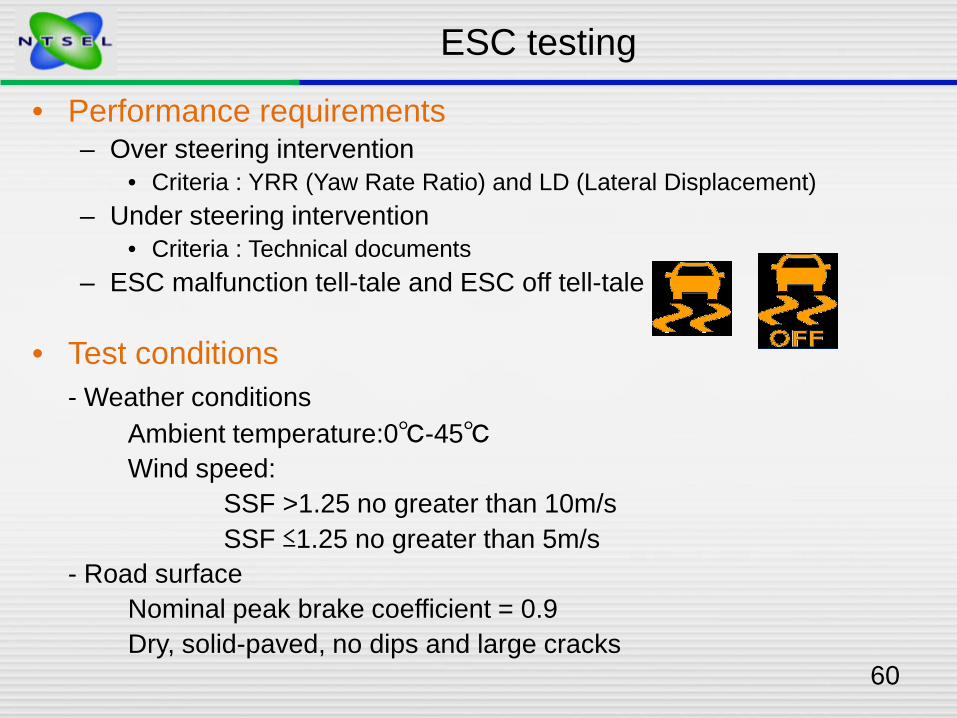
60
ESC testing
• Performance requirements– Over steering intervention
• Criteria : YRR (Yaw Rate Ratio) and LD (Lateral Displacement) – Under steering intervention
• Criteria : Technical documents– ESC malfunction tell-tale and ESC off tell-tale
• Test conditions- Weather conditions
Ambient temperature:0℃-45℃Wind speed:
SSF >1.25 no greater than 10m/sSSF ≤1.25 no greater than 5m/s
- Road surfaceNominal peak brake coefficient = 0.9Dry, solid-paved, no dips and large cracks

61
ESC testing (Outrigger)
Picture is from NHTSA document
• What is SSF ?SSF (Static stability factor) = T/2H
where T = track width, H =height of the center of gravity- In case of SSF ≤1.25, outrigger may be used for
testing safety.

62
ESC testing (Steering robot)
• Automated steering machine- Required steering pattern shall be applied by using steering robot- Capable of supplying steering torques between 40 to 60 Nm- Operate with steering wheel velocities up to 1200 deg/s
Steering robot

63
• Test sequence (1)- Brake conditioning
- Tire conditioning
ESC testing (Conditioning)
Speed (km/h) Procedure Time ABS
1 56 Braking around 4.91m/s2 10 stops Not activated
2 72 Braking higher than 4.91m/ s2 3 stops Activate
3 72 Coast driving 5 min -
Speed (km/h) Procedure Lateral acceleration
1 (Around 31 -34) Driven around a 30m circle(CW:3 ACW :3)
4.91-5.89m/s2
2 56 1Hz sinusoidal input (10 times ×4 set)

64
• Test sequence (2)- SIS ( Slowly increasing steer) test
- Dwell sine steer input test
ESC testing (SIS/DSS)
Speed (km/h) Procedure Time CW/ACW
1 80 ±2 13.5 deg/s increasing steering input 3 ACW
2 80 ±2 13.5 deg/s increasing steering input 3 CW
3 By using above 6 data, determine “Quantity A”( A = Basic steer input value at 2.94 m/s2)
Speed (km/h) Steering amplitude Max. CW/ACW1 80 ±2 From 1.5 A, increasing by 0.5A 6.5A ACW2 80 ±2 From 1.5 A, increasing by 0.5A 6.5A CW
3 By using above data, calculate values ofYRR (1s &1.75s after completion of input) and LD(1.07s after input)

65
< Movies >
ESC testing (SIS/DSS)

66
EVSC testing (R13)
• R13 annex 21- EVSC (Electric Vehicle Stability Control)
Check EVSC by choosing one demonstration from each control in the following table.
Compare dynamic manoeuvres with ON / OFF
Directional control Roll-over controlReducing radius input Steady state circularStep steer input test J-turn
Sine with dwellJ-turn
μ-split single lane changeReversed steering test or “fish hook” test
Double lane change

67
< Movies >
EVSC testing (R13)

68
Thank you for your attention

ECE Regulation 78-03
BRAKING( Category L )
<Category concerned> L3Motorcycle
Session of Technical Requirement
<System concerned> Conventional system
プレゼンター
プレゼンテーションのノート
From now Presentation item changes to Regulation 78-03

Self IntroductionMakoto Matsuo
Kawasaki Heavy Industries, LTD.
engineer
JAMAJapan Auto Mobile
AssociationsMotorcycle Brake Subcommittee
chairman
JASICBrakes and Running Gear
Subcommitteemember

Purpose of R78
・This regulation requires minimum requirement of performance and specification of Motorcycles.

History of R78
Series 00 01 02 03
Entry into force from
15 October1988
22 November1990
8 January1995
18 June2007
・Requirement on dynamic performance andtechnical specifications have been revised.
For the 03 series of amendment, technical requirement which was developed as gtr(global technical regulation) No.3 motorcycle brake system based on R78-02, FMVSS 122 and JSS12-61 has been introduced.
・So test conditions, procedures and performance-requirements are same as gtr No.3.
・Gtr No.3 includes “ statement of technical rational and justification”.
・So you can get more infomations like “backgrand”of R78-03 by reading gtr No3.
・You can find gtr No.3 in UNECE site.

Countries adopting R78
・40 countries adoptECE R78.
・There are32 administrative authorities
and 79 technical services.
> These informationcome fromECE/TRANS/WP.29/343/Rev.18
You can see more clearly in UNECE site.

CONTENTS of Regulation 78-031. Scope2. Definitions3. Application for approval4. Approval5. Specifications
5.1. Brake system requirements5.2. Durability 5.3. Measurement of dynamic performance5.4. Brake lining materials
6. Tests ( prescribed in Annex 3. )7. Modifications of vehicle type or braking system and extension of approval8. Conformity of production9. Transitional provisions
10. Penalties for non-conformity of production11. Production definitely discontinued12. Names and addresses of Technical Services responsible for conducting
approval tests and of Administrative DepartmentsANNEXES
1. Communication concerning the approval or extension or refusal or withdrawal of proposal or production definitely discontinued of atype of vehicle of category L with regard to braking pursuant toRegulation No.78
1. Appendix- List of vehicle data for the purpose of Regulation No.90 approvals2. Arrangements of approval mark3. Test conditions, procedures and performance requirements

1. Scope
This regulation applies to vehicles of categories L1, L2, L3, L4 and L5.・Categories are defined in Annex 7 to the Consolidated Resolution on the
Construction of Vehicles ( R.E.3 )・These categories do not include:
(a) Vehicles with a Vmax < 25 km/h.(b) Vehicles equipped for disabled riders.
Today’s presentation is for category L3
Category wheel Engine capacity Max speedL1 two ≦50cm3 ≦50km/hL2 three ≦50cm3 ≦50km/hL3 two 50cm3< 50km/h<L4 Three
( asymmetrically arranged )( motor cycle with sidecars )
50cm3< 50km/h<
L5 Three( symmetrically arranged )
50cm3< 50km/h<

2. Definitions – 1/4 ( definition of brake parts )・”Brake system” means
the combination of parts consisting of the control, transmission, and brake, but excluding the engine, whose function is to progressively reduce the speed of a moving vehicle, bring it to a halt, and keep it stationary when halted.
・”Control” means the part actuated directly by the rider in order to supply or control the energy required for braking the vehicle to the transmission.
・”Transmission” means the combination of components that provide the functional link between the control and the brake.
・“Brake” means those parts of the brake system where the forces opposing the movement of the vehicle are developed.
・”Service brake system” means a brake system which is used for slowing the vehicle when in motion.

2. Definitions – 2/4= + +
Brake pedal
Brake pedal
Brake lever
Master cylinder
Brake disc
caliperBrake disk
caliper
Brake hose
reservoir
Master cylinder
Brake lever
reservoirMaster
cylinder
Brake hose
reservoir
Control Transmission BrakeBrake system
Service brake system

2. Definitions – 3/4 ( Definition of test weight )・”Laden” means so loaded as to attain the gross vehicle mass which is the technically permissible maximum laden mass as declared by the manufacture.
・“Lightly loaded” means mass in running order plus 15 kg for test equipment, or the laden condition, whichever is less.
・”Mass in running order” means the sum of the unladen vehicle mass and driver mass.
・”Unladen vehicle mass” means the nominal mass of the vehicle as indicated by the manufacturer(s) including all factory fitted equipment for normal operation of that vehicle, plus coolant, oil, 90% of fuel and 100% of other gas or liquids, as specified bythe manufacturer.
・”Driver mass” means the nominal mass of a driver that shall be 75kg ( subdivided into 68kg occupant mass at the seat and 7kg luggage mass )
Unladen vehiclemass
Driver mass
15kg( test
equipment )
Mass in running order
Lightly loaded
Passenger,etc
Laden

2. Definitions – 4/4 ( other definition )
・“Engine disconnect” means when the engine is no longer connected to the drive wheel(s).
・”Test speed” means the vehicle speed measured the moment the driver begins to actuate the brake control(s). For tests where the simultaneous action of two controls is specified,the vehicle speed is taken from the point the first control is actuated.
・”Stopping distance” means the distance traveled by the vehicle from the point the rider begins to actuate the brake control to the point at which the vehicle reaches a full stop.For tests where the simultaneous action of two controls is specified, the distance traveled is taken from the point the first control is actuated.

5.1. Brake system requirements1. Vehicles shall have configurations
that enable a rider to actuate the service brake system control ・ while seated in the normal driving position and・ with both hands on the steering control.
2. Vehicles shall be equipped with two separate service brake system, ・ with at least one brake operating on the front wheel and ・ at least one brake operating on the rear wheel.
3. In cases where two separate service brake systems are installed, ・ the systems may share a common brake, if a failure in one system
dose not affect the performance of the other.4. For vehicles that use hydraulic fluid for brake force transmission,
the master cylinder shall:(a) Have a sealed, covered, separate reservoir;(b) Have a minimum reservoir capacity
・ equivalent to 1.5 times the total fluid displacement ・ required to satisfy the new to fully worn lining condition ・ with the worst case brake adjustment condition;
(c) Have a reservoir where ・ the fluid level is visible for checking ・ without removal of the cover.

5.2. Durability1. Wear of the brakes shall be compensated for
by means of ・a system of automatic or ・manual adjustment.
2. The friction material thickness shall either ・be visible without disassembly, or ・where the friction material is not visible,
wear shall be assessed by means of a device designed for that purpose.3. During all tests in this Regulation and on their completion,
・there shall be no friction material detachment and ・no leakage of brake fluid.
5.4. Brake lining materials
・Brake linings shall not contain asbestos.

5.3. Measurement of dynamic performance – 1/61. MFDD ( Mean Fully Developed Deceleration )
MFDD = ( Vb2 - Ve2 ) / 25.92 ( Se - Sb ) in m/s2
where;V1 = vehicle speed when rider actuates the controlVb = vehicle speed at 0.8 V1 in km/hVe = vehicle speed at 0.1 V1 in km/hSb = distance travelled between V1 and Vb in metersSe = distance travelled between V1 and Ve in meters
2. Stopping distance;To calculate the corrected stopping distance ( Ss ) using the actual vehicle test speed,
Ss = 0.1Vs + ( Sa – 0.1Va )・Vs2/ Va2
where;Vs = specified vehicle test speed in km/hSa = actual stopping distance in metresVa = actual vehicle test speed in km/h
Note; This equation is only valid when the actual test speed( Va )is within ±5km/h of the specified test speed ( Vs ).
3. Continuous deceleration recordingFor the burnishing procedure and tests such as wet brake, heat fade-heating procedure, there is a continuous recording of the vehicle’s instantaneous
deceleration from the moment a force is applied to the end of the stop.

5.3. Measurement of dynamic performance – 2/6Sample of the measurement data ( Dry stop test – single brake :
Front ) The moment a force is applied
The end of the stop
Vehicle speed
deceleration
Brake actuation force Brake
temperature

5.3. Measurement of dynamic performance – 3/6 ( MFDD )
V1 Vb Ve STOP
= 0.8V1 = 0.1V1
Sb
Se
MFDD = ( Vb2-Ve2)/25.92 ( Se – Sb ) in m/s2
Rider actuates the control
Distance travelled Between V1 and Vb
Distacce travelledBetween V1 and Ve
Braking

5.3. Measurement of dynamic performance – 4/6 ( MFDD )• MMFDD is the vehicle deceleration calculated between 80 and 10 % of the vehicle• intial speed.
Vb km/h = Vb ×1000/3600 m/s = Vb ×1/3.6 m/s
Ve km/h = Ve ×1/3.6 m/s
MFDD = ( Vb – Ve ) / t
( Se – Sb ) = ( Vb + Ve ) ×t ×1/2
t = 2 ( Se – Sb ) / ( Vb + Ve )
MFDD = ( Vb – Ve ) ( Vb + Ve ) / 2( Se – Sb )
= ( Vb – Ve ) ×1/3.6 ( Vb + Ve ) ×1/3.6 / 2( Se – Sb )
= ( Vb2- Ve2 ) / 25.92 ( Se – Sb )
Vb
Ve
V1
timet
speed
Vb-Ve
SeSb
Se - Sb
This is calculation to change unit from km/h to m/s
This is equation to get the deceleration rate.
This is equation to get the area of trapezoid.
Changing the equations

5.3. Measurement of dynamic performance – 5/6 ( Stopping distance )
Vs
Va
Sa
Specified test speed in km/h
Actual test speed in km/h STOP
Actual stopping distance in metresSs: corrected stopping distance
= 0.1Vs + ( Sa – 0.1Va ) ・ Vs2/Va2
Should be within ±5km/h of the Vs
Braking
0.1Va Sa – 0.1Va
0.1Vs ( Sa – 0.1Va)・Vs2/Va2Ss

5.3. Measurement of dynamic performance – 6/6 ( Stopping distance )
Stopping distance:Based on the basic equations of motion:
S=0.1・V+ (X)・V2
WhereS=stopping distance in metersV=vehicle speed in km/hX=a variable based on the requirement for each test ( deceleration )0.1・V is a factor for the brake system reaction time.
・Stopping distance performance requirements are set for a specified initial test speed.・While professional test riders can approach this initial test speed,
it is unlikely that the test will be started at the exact speed specified, affecting thestopping distance requirement.
・So it is necessary to correct the measured stopping distance to compensate for thedifference between the specified test speed and the actual speed where the brakewere applied.
Ss = 0.1Vs + (Sa – 0.1Va)・(Vs/Va )2
Corrected stopping distance
A factor for the reaction time by the specified test speed
Stopping distance by actual test speed without a factor for the reaction time
Ratio of specified speed and actual test speed
This explanation is in R78-03
Stopping distance by specified test speed without a factor for a reaction time

Preparation and Test sequence
Test sequence Vehicle Remarkscondition
1 Burnishing Lightry Preparation for testLoaded
2 Dry stop test – single brake control actuated
Laden
3 Dry stop test – all service brake controls actuated
Lightry loaded
4 High speed test Lightly loaded
5 Wet brake test Laden
6 Heat fade test Laden

Annex 3 2. Preparation5.Burnishing procedure
( This procedure may be completed by the manufacture )・Vehicle lightly loaded;・Engine disconnected;・Test speed;
・Brake application;Each service brake system control actuated separately;
・Vehicle deceleration;
・Number of decelerations; ・Initial brake temperature before each brake application;
Less than 100℃・After burnishing,
Initial Final50km/h or 0.8Vmax, lower 5 ~ 10km/h
Front 3.0~3.5m/s2
Rear 1.5~2.0m/s2
Braking
100 per brake system
Adjust the brakes in accordance with the manufacture’srecommendations.
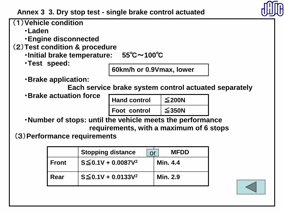
Annex 3 3. Dry stop test - single brake control actuated(1)Vehicle condition
・Laden・Engine disconnected
(2)Test condition & procedure・Initial brake temperature: 55℃~100℃・Test speed:
・Brake application: Each service brake system control actuated separately
・Brake actuation force
・Number of stops: until the vehicle meets the performance requirements, with a maximum of 6 stops
(3)Performance requirements
Hand control ≦200NFoot control ≦350N
Stopping distance MFDDFront S≦0.1V + 0.0087V2 Min. 4.4
Rear S≦0.1V + 0.0133V2 Min. 2.9
or
60km/h or 0.9Vmax, lower

Annex 3 4. Dry stop test – all service brake controls actuated
(1)Vehicle condition・Lightly loaded・Engine disconnected
(2)Test condition & procedure・Initial brake temperature: 55℃~100℃・Test speed: ・Brake application: Simultaneous actuation of both brake
・Brake actuation force
・Number of stops: until the vehicle meets the performance requirements, with a maximum of 6 stops
(3)Performance requirements
Stopping distance MFDDS≦0.0060V2 -
Hand control ≦250NFoot control ≦400N
100km/h or 0.9Vmax, lower

Annex 3 5. High speed test ( not required for vehicles with Vmax ≦ 125km/h )(1)Vehicle condition
・Lightly loaded・Engine connected with the transmission in the highest gear
(2)Test condition & procedure・Initial brake temperature: 55℃~100℃・Test speed:
・Brake application: Simultaneous actuation of both service brake system controls
・Brake actuation force
・Number of stops: until the vehicle meets the performance requirements, with a maximum of 6 stops
(3)Performance requirementsStopping distance MFDDS≦0.1V + 0.0067V2 Min. 5.8
Vehicle max speed Test speed125km/h< <200km/h 0.8 Vmax200km/h≦ 160 km/h
Hand control ≦200NFoot control ≦350N
or

Annex 3 6. Wet brake test 1/2(1)General
・For each brake system.・Drum brakes or fully enclosed disc brakes are exempt from this test
unless ventilation or open inspection ports are present. (2)Vehicle condition
・Laden ・Engine disconnected・Each brake is fitted with water spray equipment
(3)Baseline test・Dry stop test
With the brake control force that results in a vehicle deceleration of 2.5 ~ 3.0m/s2 , and the following is determined;
・Conduct 3 baseline stops and average the values
①Average brake control force measured when the vehicle istraveling between 80% and 10% of the specified test speed.
②Average vehicle deceleration in the period 0.5 to 1.0seconds after the point of actuation of the brake control.
③Maximum vehicle deceleration during the complete stopbut excluding the final 0.5 seconds.

Annex 3 6. Wet brake test 2/2
(4)Wet brake stop(a)The vehicle is ridden at the test speed used in the baseline test with
the water spray equipment operating on the brake(s) andwith no application of the brake system;
(b)After a distance of ≧500m, apply the averaged brake control forcedetermined in the baseline test ;
(c)Measure the average vehicle deceleration in the period 0.5 to 1.0seconds after the point of actuation of the brake control;
(d)Measure the maximum vehicle deceleration during the complete stopbut excluding the final 0.5 seconds.
(5)Performance requirement
Average vehicle deceleration in the period 0.5 to 1.0 seconds after the point of actuation of the brake control
≧60% of the baseline test
Maximum vehicle deceleration during the complete stop but excluding the final 0.5 seconds
≦120% of the baseline test
and

Annex 3 7. Heat fade test 1/3
(1)General・ Vehicle; laden.・ Each service brake system control actuated separately
(2)Baseline test・Dry stop test - single brake control actuated・Measurement of either MFDD or the stopping distance.
(3)Heating procedure・Test speed
・Engine transmission
・Initial brake temperature prior to first stop only; 55℃ ≦ ≦ 100℃
Test speed V 0.5V 0Enginetransmission
connect with the highest Disconnected appropriate gear
Front brake 100km/h or 0.7Vmax, lowerRear brake 80km/h or 0.7Vmax, lower
Braking

Annex 3 7. Heat fade test 2/3
・Brake actuation force;・Constant control force・Vehicle deceleration rate of 3.0 – 3.5m/s2 between80% and 10% of the specified speed
・Carry out a stop , then immediately use maximumacceleration to reach the specified speed and maintain that speed until the next stop.
Number of stop; 10Interval between stops; 1000m

Annex 3 7. Heat fade test 3/3
(4)Hot brake stop・Conditions used in the baseline test.・Within one minute of the completion of the heating procedure. ・Brake actuation force; less than or equal to the force used in thebaseline test.
・Measurement of either MFDD or the stopping distance.
(5)Performance requirements
Stopping distance MFDD
S≦1.67S1-0.67×0.1VwhereS1; stopping distance in
the baseline testV ; specified test speed in km/h
More than 60% of the MFDDin the baseline test
or

ENDThank you so much for your attention!
Next presentation is for
Test Procedure.
2010/12/21 1
Toru IHARA
NTSELNational Traffic Safety and Environment Laboratory
Nov. 2010
Braking test procedure
R78-03

2010/12/21 2
2.Facility & equipment
3.Test Procedure
R78 Braking for L categories
Contents
(1)Facility
(2)Equipment for R78 test
(3)Calibration
1.Scope and focus

2010/12/21 3
Category Wheel Engine capacity Max speedL1 Two ≦50cm3 ≦50km/hL2 Three ≦50cm3 ≦50km/hL3 Two 50cm3< 50km/h<
L4 Three( asymmetrically arranged )( motor cycle with sidecars )
50cm3< 50km/h<
L5 Three( symmetrically arranged )
50cm3< 50km/h<
Scope and Focus
• In Japan It is mandatory for L3 category vehicles to undergo national periodical inspections. Therefore NTSEL mainly tests for L3 category vehicles.

2010/12/21 4
2.Facility & equipment
3.Test Procedure
R78 Braking for L categories
Contents
(1)Facility
(2)Equipment for R78 test
(3)Calibration
1.Scope and focus

2010/12/21 5
Test Track and ABS test surface
- High friction surface:Peak brake coefficient
nominal 0.9 Lane width
2.5m
- Low friction surface:Peak brake coefficient
≤ 0.45 Lane width
2.5m
The PBC is measured by using ASTM E1337-90 or Appendix 1 of Annex 3

2010/12/21 6
Check points Service braking and braking with
failure
ABS
Braking temperature before braking
O O
Initial braking speed and stopping distance
O O
Mean fully developed deceleration
O O
Force applied to control O O
Wheel lockup O O
Vehicle behavior O O
Deceleration time O
Equipment
Thermocouples
Speed sensor( G sensor )
Measuring gauge of control force
Wheel speed sensor
Visual check
Measuring unit(Generated from data)

2010/12/21 7
Thermocouple
Front : Right side
Rear : Left side
Thermocouples

2010/12/21 8
GPS Speed sensor
Integrated G sensorin GPS UNIT
Speed sensor

2010/12/21 9
Measuring gauge of control force
Force sensor
Strain gauge
Hydraulic sensor Control force is converted from measured hydraulic

2010/12/21 10
Measuring equipment
Measurement unit
・ Deceleration time・ MFDD・ Temperature
before braking・ Stopping distance
Display and meters
・Deceleration
・Braking force
・Vehicle speed
・ Stopping distance
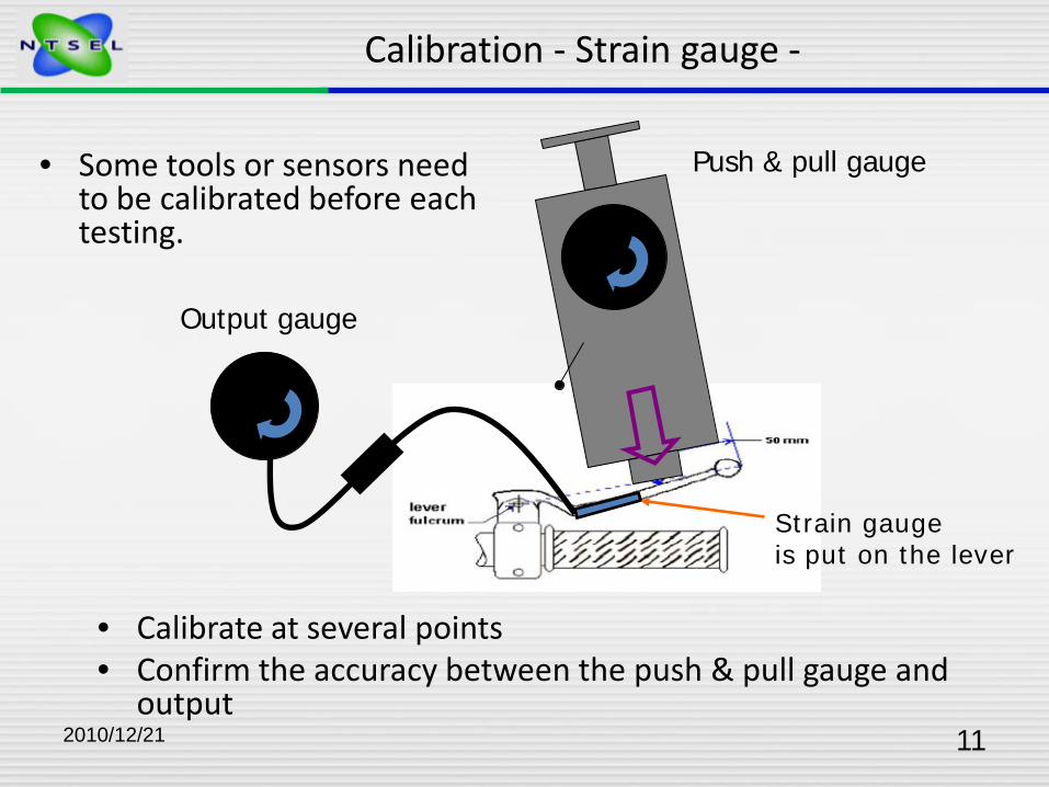
2010/12/21 11
• Calibrate at several points • Confirm the accuracy between the push & pull gauge and
output
Push & pull gauge
Calibration - Strain gauge -
Output gauge
• Some tools or sensors need to be calibrated before each testing.
Strain gauge is put on the lever

2010/12/21 12
2.Facility & equipment
3.Test Procedure
R78 Braking for L categories
Contents
(1)Facility
(2)Equipment for R78 test
(3)Calibration
1.Scope and focus

2010/12/21 13
Checking points before testing
• Confirmation of testing vehicle- Vehicle Type and number- Type of ENG- Tire size and inflation pressure- Measurement equipment
and its calibration - Confirmation of testing vehicle
Braking parts / modified parts for testing- Measurement mass
• Confirmation item of test condition- Weather conditions
Ambient temperature:0 - 45℃Wind speed:Not more than 5 m/s
- State of testing road surface

2010/12/21 14
Confirmation of testing vehicle
Water spray for wet brake test
Water spray
Water tank

2010/12/21 15
Cut valve unit
Confirmation of testing vehicle
For adjusting control force during the test

2010/12/21 16
Measurement mass
• Laden condition (Maximum mass)– The technically permissible maximum laden mass as specified by
manufacturer
• Lightly loaded condition– “Mass in running order” + 15kg ( 30kg: ABS test on a low friction surface)
• Mass in running order– “Unladen vehicle mass” + “Driver mass”
• Unladen vehicle mass– The nominal mass of the vehicle as specified by manufacturer– Including tools, oils, 90 % fuel and 100 % of other liquids
• Driver mass– Nominal mass of a driver 75 kg
• =( driver 68kg + luggage 7kg )

2010/12/21 17
Measurement mass
Specification Test condition
Unladen vehicle mass 247kg -
Mass in running order 247+75kg(Driver) = 322kg
Lightly loaded condition 322+within 15kg322+within 30kg(ABS)
= 332kg338kg
Laden condition(Maximum mass)
421kg < 423kg
Distribution of mass as specified by manufacturer
Fr:155kgRr:266kg
Fr:153kgRr:270kg
- Laden condition in test may exceed Maximum mass
- The allowance of distributed mass in test is within ±10kg

2010/12/21 18
Corrected stopping distance
Ss=0.1Vs+(Sa-0.1Va)×Vs2/Va2
Ss = corrected stopping distance in metersVs = specified vehicle test speed in km/hSa = actual stopping distance in metersVa = actual vehicle test speed in km/h
Ex) Dry stop test –single brake control actuated-
Specified speed : 100km/h
Braking speed : 101.5km/h
Stopping distance : 38.2m
Ss=0.1×100+(38.2-0.1×101.5)
×100^2/101.5^2
=37.51
=37.5m
This equation is only valid when Va is within +/- 5 km/h of Vs.
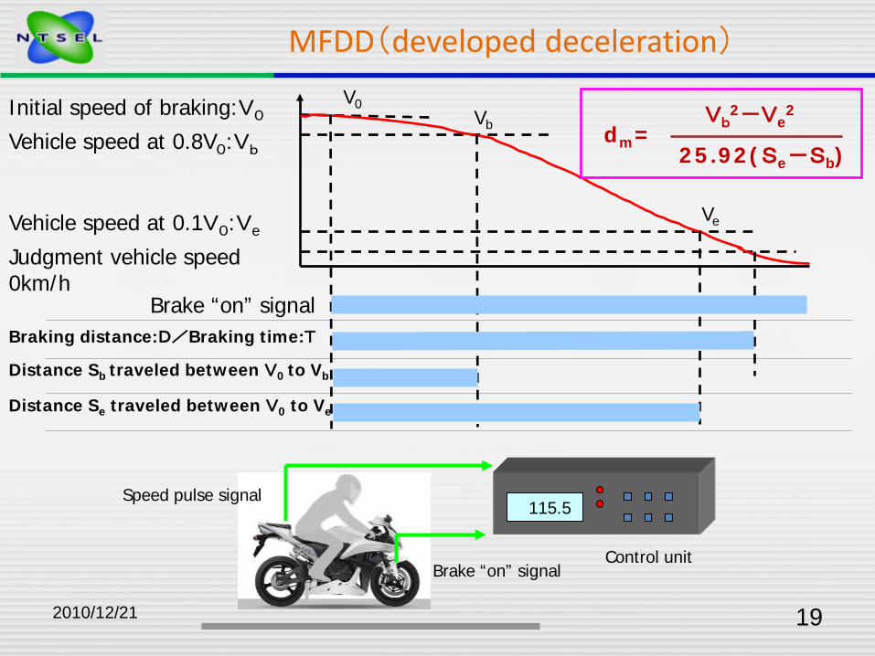
2010/12/21 19
MFDD(developed deceleration)
115.5Speed pulse signal
Brake “on” signalControl unit
V0
Ve
VbInitial speed of braking:V0
Vehicle speed at 0.8V0:Vb
Vehicle speed at 0.1V0:Ve
Judgment vehicle speed 0km/h
Brake “on” signalBraking distance:D/Braking time:T
Vb2-Ve
2
25.92(Se-Sb)dm=
Distance Sb traveled between V0 to Vb
Distance Se traveled between V0 to Ve

2010/12/21 20
Checking of behavior during brake testing
Vehicle behavior The vehicle is positioned in the center of the test lane for the beginning of each stop
Stops are made without the vehicle wheels passing outside the applicable test lane and without wheel lock

2010/12/21 21
R78 Test overview
TestR78
Annex3
1.Brake
1. Dry stop test –single brake control actuated- 3
2. Dry stop test -all service brake controls actuated- 4
3. High speed test 5
4. Wet brake test 6
5. Heat fade test 7
2.Parking brake Parking brake system test 8
3.Others
1. ABS test 9
2. Partial failure test –for split service brake systems 10
3. Power-assisted braking system failure test 11
4. Peak braking coefficient 1.1.3Appendix 1
Heat fade is always the last test to be carried out.
Conventional L3 tests are above highlighted items

2010/12/21 22
Dry stop test -single brake control actuated- (L3)
60km/h or 0.9Vmax ,whichever is lower
○Pad temperature before braking :55~100℃
○Initial speed of braking
○Gear position :engine disconnected or N
time(t)
Braking point
Veh
icle
sp
eed
(V
)
Stopping distance
-Carried out for each brake, such as only front, only rear
(rear)
(front)

2010/12/21 23
Dry stop test -single brake control actuated- (L3)
StoppingdistanceorMFDD
Front:0.1 v+0.0087v2 or lessRear: 0.1 v+0.0133v2 or less
Front: 4.4m/s2 or moreRear: 2.9m/s2 or more
Control force Less than 200N(Hand)Less than 350N(Foot)

2010/12/21 24
100km/h or 0.9Vmax ,whichever is lower
time(t)
Braking point
○Pad temperature before braking : 55~100℃
○Initial speed of braking
Veh
icle
sp
eed
(V
)
○Gear position :engine disconnected or N
Dry stop test -all service brake controls actuated- (L3)
Stopping distance
Stopping distance
0.0060v2 or less
Control force
Less than 250N(Hand)Less than 400N(Foot)
- Apply all service brakes (front &rear)
-The criteria is only stopping distance in lightly loaded condition
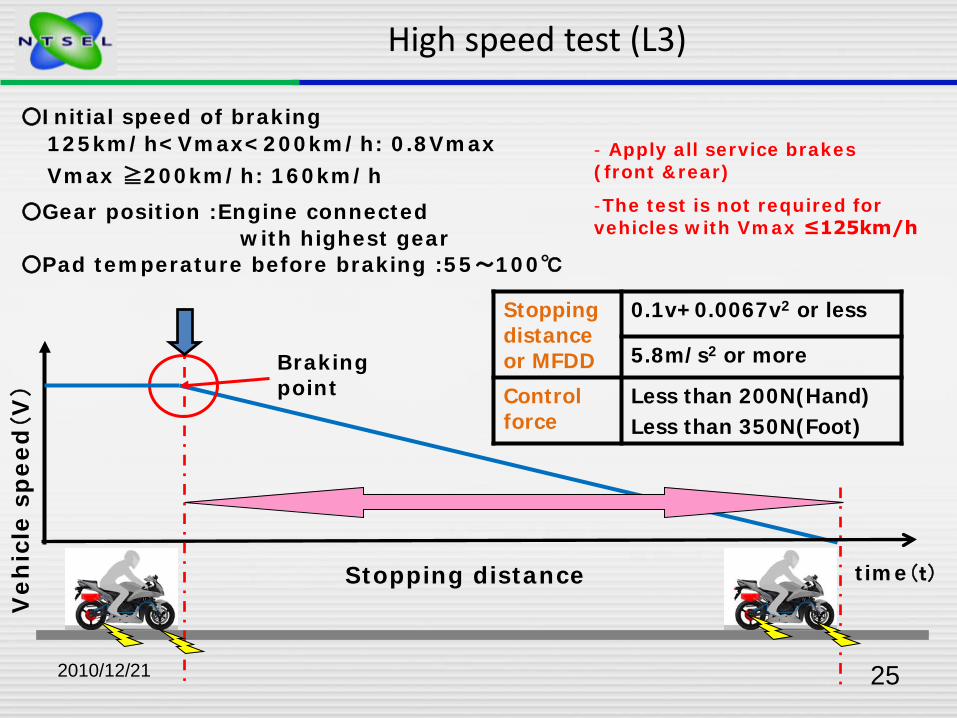
2010/12/21 25
High speed test (L3)
125km/h<Vmax<200km/h: 0.8VmaxVmax ≧200km/h: 160km/h
○Pad temperature before braking :55~100℃
○Initial speed of braking
○Gear position :Engine connected with highest gear
time(t)
Braking point
Veh
icle
sp
eed
(V
)
Stopping distance
Stopping distance or MFDD
0.1v+0.0067v2 or less
5.8m/s2 or more
Control force
Less than 200N(Hand)Less than 350N(Foot)
- Apply all service brakes (front &rear)
-The test is not required for vehicles with Vmax ≤125km/h

2010/12/21 26
Wet brake test(Overview) (L3)
The test is comprised of 2 parts for each brake system in laden condition.In case of CBS, the vehicle is tested in the lightly loaded condition also.(i) A baseline test based on the dry stop test - single brake control
actuated (ii) A single wet brake stop
Before the test, it is necessary to confirm the vehicle conditionwith water spray as follows:- Installation of water spray- Position of its nozzle- Flow rate of water spray
15L / min
Confirmation of flow rate
Drum brakes or fully enclosed disc brakes are exempt from this test unless ventilation or open inspection ports are present

2010/12/21 27
80%V
10%V
60km/h or 0.9Vmax ,whichever is lower
○Pad temperature before braking :55-100℃
○Initial speed of braking
○Gear position : Engine disconnected or N
time(t)
Braking point
Veh
icle
sp
eed
(V
)Wet brake test(baseline test)
Initial speed of braking
Deceleration between 80% and 10% of the specified test speed:2.5~3.0m/s2. Control force is to become this deceleration
D1= The average vehicle deceleration in the period 0.5s to 1.0s after the braking point
D2= The maximum vehicle deceleration during the complete stop but excluding the final 0.5s
-Carried out for each brake
Average the above 4 values from 3 stops
○Measure D1 ,D2, Deceleration and Control force.
(Front)

2010/12/21 28
Before Wet brake stop, the vehicle shall be driven at the initial speed over 500m with water spray operating
time(t)
Braking point
Veh
icle
sp
eed
(V
)
Wet brake test(Wet brake stop)
60km/h or 0.9Vmax ,whichever is lower
○Pad temperature before braking :55-100℃
○Initial speed of braking
○Gear position : Engine disconnected or N Carried out for each brake
○Control force: Determined force of baseline
Average deceleration(DW1)
DW1
≧0.6×D1
Maximum deceleration(DW2)
DW2
≦1.2×D2
○Measure DW1 and DW2 , and compare with D1 and D2 of baseline
(Front)

2010/12/21 29
Heat fade test(Overview)
The test is comprised of 3 parts for each brake system in ladencondition that are carried out consecutively for each brake system.
(i) A baseline test using the dry stop test - single brake control actuated
(ii) A heating procedure which consists of a series of repeated stops in order to heat the brake system
(iii) A hot brake stop using the dry stop test - single brake control actuated, to measure the brake's performance after the heating procedure
The test is not applicable to parking brake systems and secondary service brake systems
Before the baseline test, it is necessary to confirm the interval distance in heating procedure is 1000m

2010/12/21 30
Heat fade test(baseline test)
60km/h or 0.9Vmax ,whichever is lower
○Pad temperature before braking :55-100℃
○Initial speed of braking
time(t)
Braking point
Veh
icle
sp
eed
(V
)
Stopping distance
Initial speed of braking
○Gear position :engine disconnected or N
Stopping distance or MFDD
0.1v+0.0067v2 or less
5.8m/s2 or more
Control force
Less than 200N(Hand)Less than 350N(Foot)
Carried out for each brake
(rear)
(front)

2010/12/21 31
Interval: 1000±0100m
repeat 10 times
Heat fade test(Heating procedure)
- Front: 100km/h or 0.7Vmax ,whichever is lower- Rear: 80km/h or 0.7Vmax ,whichever is lower
○Pad temperature before braking :55-100℃
○Initial speed of braking
○Gear position : Engine connected with the transmission in highest gear
Veh
icle
sp
eed
(V
)
distance
Deceleration between 80% and 10% of the specified test speed:3.0~3.5m/s2. Control force is to become this deceleration. Therefore, before the heating procedure, the pre-test may be necessary to determine control force.
Each brake

2010/12/21 32
Carried out within one minute after heating procedure
60km/h or 0.9Vmax ,whichever is lower○Initial speed of braking
time(t)
Braking point
Veh
icle
sp
eed
(V
)
Stopping distance
Heat fade test(Hot brake stop)
Initial speed of braking
○Gear position :engine disconnected or N○Control force: less than baseline force
Each brake
Stopping distance or MFDD
S2≦1.67S1-0.67×0.1VS1: Corrected stopping distance in the baseline test (m)
S2: Corrected stopping distance in the hot brake stop (m)
dh≧0.6dcdc:MFDD in the baseline test (m/s2)
dh:MFDD in the hot brake stop (m/s2)

2010/12/21 33
< Movies >
ABS tests

2010/12/21 34
Thank you for your attention

第23回アジア専門家会議概要報告
「ブレーキに関する専門家会議」
1. 日時: 2010.11.23 9:00~16:30
2. 場所: マレーシア運輸局大会議室
3. 開催者:マレーシア運輸局(JPJ)
4. 出席者:マレーシア運輸省(MOT)、運輸局(JPJ),規格・工業調査局(SIR
IM)、自動車工業会、(MAA)、等、合計約35名
5. 日本側出席者:R13H技術要件の説明者として石原氏(トヨタ)、R13技術要件
の説明者として大澤氏(いすゞ)、R78技術要件の説明者として松尾氏(川崎)、
R13H・R13・R78の試験要件の説明者として伊原氏(NTSEL)、
事務局として JASIC 南部 合計5名
6. 内容概要
主催者を代表して道路安全局長 DATO’ SURET SINGH 氏よりキーノートスピーチを頂
いた後、JASIC側からのプレゼンと質疑を通じ、マレーシア関係者の疑問を解消、
会議は和やか且つ盛況の内に終了した。
<Malaysia 側のキーノートスピーチ>
マレーシアは1998年の第一回JASIC会議に参加して以来、WP29のメンバ
ーとなることの重要性や世界的な車両法規調和の利点を認識している。ひとつはコスト
ダウン、認証プロセスの簡素化、そして各国間の貿易障壁を取り除くためにも必要であ
る。自動車や2輪を含むマレーシアの産業は劇的に発展した。自動車を生産し輸出し始
めたし、一方で法令や認証プロセスの遵守での障害を経験もした。WP29の58、9
8協定への参画は自動車産業に恩恵をもたらすだろう。
本日のテーマである車両ブレーキシステムに関しては、ブレーキの故障による事故が
マレーシアも含め全世界で取り沙汰されている。ブレーキシステムは重要なシステムと
して既に紹介されているが、ユーザにとってはその機能が働かなければ、非常に危険な
ものとなる。本日、日本から来た同胞はブレーキの全ての技術的要件を説明してくれる。
政府としても早急にこの法規を採用したいし、この専門家会議を産業界の目覚めの第一
歩としたい。そして説明いただく内容をマレーシアの自動車システムに適用して行きた
い。

<日本 JASIC 側のプレゼン>
1)乗用車ブレーキ(R13H)の技術要件について
(石原氏/トヨタ)
冒頭 GRRF のルールメイキングでの位置付け、法規作成の理念等の説明の後,乗用車ブ
レーキ法規規制値の変遷、現在の規制状況、各国の採用状況、基本的要求事項、試験
条件、新技術の内容法規策定への準備などについて説明した。
今後進めてゆく予定のブレーキ試験の詳細について理解を深めることが出来た。
2)トラック・バスブレーキ(R13)の技術要件について
(大澤氏/いすゞ)
R13Hに含まれないR13特有の技術要件を中心に、ブレーキシステムの内容・機
能も含め、各構造・機能への要求事項、試験条件などについて説明した。さらに活発
な質疑応答が行われ、疑問点について理解を深めることができた。
3)2輪ブレーキ(R78)の技術要件について
(松尾氏/川崎)
法規の目的、歴史、採用国、法規内容、適用範囲、各用語の定義、要求事項、各試験
内容などについて説明した。さらに活発な質疑応答が行われ、疑問点について理解を
深めることができた。
4)乗用車ブレーキ(R13H)、トラック・バスブレーキ(R13)、2輪ブレーキ(R
78)の試験要件について
(伊原氏/NTSEL)
認証の流れ、設備、装置、試験対象の仕様・構造・挙動確認、試験条件、各種試験の内
容、ABS・EBS・EVSC 試験の内容(テストシーンビデオ含む)などについて説明した。さらに活発
な質疑応答が行われ、疑問点について理解を深めることができた。
[R13H、R13技術要件についての主な質疑]
Q1:認証に要する時間はどれほど?
A1:日本では平均してテクニカルレポート作成に6週間、そのあと認可証発行までに2
週間位の期間が必要(伊原)。
Q2:ワーニングに対しどういう状態がOKなのか?
A2:故障時点灯で有り、OK な状態は無い。但し通常赤色に対し電気的な故障は黄色。
又 EBS の電気的故障については正常時票件を満たす場合には黄色。それを下回る場合に
は赤色が規定されている。(石原)。
Q3:(故障車や駐車違反車両の前軸や後軸を乗っけて引っ張る)トーイングトラクタは、
カテゴリーNなのかOなのか?R13はどのようにすればよいのか?
A3:あとで回答する。(大澤)

回答;
故障車や駐車違反車両の前軸や後軸を乗っけて引っ張るトーイングトラクタはカテゴ
リーNとなる。
R13のトラックの規定は適用するが、R13のトラクタ(牽引車)の規定は適用しな
い。
理由;
R13の牽引車の規定は、「In the case of a power-driven vehicle authorized to tow
a trailer of category O3 or O4 」や「In the case of a power-driven vehicle authorized
to tow an unbraked trailer」などの前提条件があり、牽引する事が authorized され
た車両に適用される。
R13で牽引する事が authorized された車両とは、正常時に牽引する事が authorized
された車両であって、非常時の牽引は該当しない。
故障車や駐車違反車両の前軸や後軸を乗っけて引っ張るトーイングトラクタは非常時
の牽引であり、R13法規上の牽引車には該当しない。
[R13、R13Hの試験要件についての主な質疑]
Q1:Type-I fade and recovery test の一連の所要時
間は?また、2日に分けて実施できないのか?
A1:約2時間です。Heating から Recovery までを一日で実施しないといけない。(伊原)
Q2:RBSやBASの説明は?
A2:BASはまだ経験が無い。RBSはメーカーの説明でニュートラルでほとんどRB
Sが作動しないためニュートラルで実施すればRBSでも通常のブレーキと大きな違
いはない。(伊原)
Q3:KLKHとは?
A3:それぞれ低μ、高μの摩擦係数を示している。(伊原)
Q4:ESC試験でタイヤコンディショニングで違う速度でABS作動有無で2回やるの
はなぜか?
A4:、gtr を経てUSの意見も踏まえ定めているため。(石原)
Q5:ESC試験用のアウトリガーの仕様指定はあるのか?
A5:車両重量などによって規則の附則9に仕様の記載がある。(伊原)
[R78技術要件及び試験要件についての主な質疑]
Q1:運転者体重条件75kgは世界的なものか?
A1:そうです。内訳はドライバ自身の68kgと付属物7kgです。(松尾)
Q2:家族全員(出た事例は大人 2 人、子供 2人)が乗っているケースもあるが大丈夫か?
A2:製造元が称している車両総重量以下であればOKである。逆に質問だが、法規上何
人も乗っていいのですか?(伊原)

A2-1:2人までしか認められていません(JPJ)。
Q3:制動距離の代わりにMFDD(Mean Fully Developed zd
eceleration)を選択することができるのか?
A3:その通り。その際、計測速度の許容値は±5km/hであることに注意せねばなら
ない。(伊原)
Q4:高速試験はエンジンサイズには関わらないのか?また油圧ブレーキはどうするの
か?
A4:エンジンサイズには関わらない。最高速により分類される。(松尾)
A4-1:油圧ブレーキの場合は圧力コントロールが難しいため、カットバルブを使用して
油圧から操作力を換算して試験をしている。(伊原)
Q5:電動2輪の規定はないのか?
A5:現時点では特に定められていない。(松尾)
A5-1:電動かどうかはRBSがなければブレーキには関係ない。(伊原)
以上