R&D Activities on High Field and HTS Magnets at BNL · R&D Activities on High Field and HTS Magnets...
70
High Field/HTS Magnet R&D at BNL Ramesh Gupta Sept 21, 2014 1 Superconducting Magnet Division R&D Activities on High Field and HTS Magnets at BNL Ramesh Gupta Brookhaven National Laboratory Upton, NY 11973 USA September 21, 2014
Transcript of R&D Activities on High Field and HTS Magnets at BNL · R&D Activities on High Field and HTS Magnets...

High Field/HTS Magnet R&D at BNL Ramesh Gupta Sept 21, 2014 1
Superconducting Magnet Division
R&D Activities on High Field
and HTS Magnets at BNL
Ramesh Gupta
Brookhaven National Laboratory
Upton, NY 11973 USA
September 21, 2014

High Field/HTS Magnet R&D at BNL Ramesh Gupta Sept 21, 2014 2
Superconducting Magnet Division
First - Personal Thanks
Thank you for inviting me and for asking our
participation in CEPC-SppC. I enjoyed my
stay here and appreciate your hospitality. Selfie

High Field/HTS Magnet R&D at BNL Ramesh Gupta Sept 21, 2014 3
Superconducting Magnet Division
Contents
• Alternate Magnet Designs
– Common Coil
– Open Midplane Dipole
15 T good field quality magnetic design for both will be presented
• Progress in HTS Magnet Technology at BNL
• A few thoughts on R&D Plan (separate file)
• Summary
Note: This presentation is limited to the research program at BNL only - mostly in the areas
where it has made significant contributions and are relevant to future SppC magnet R&D.
High Field/HTS Magnet R&D at BNL Ramesh Gupta Sept 21, 2014 4
Superconducting Magnet Division
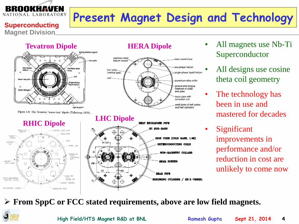
Present Magnet Design and Technology
• All magnets use Nb-Ti
Superconductor
• All designs use cosine
theta coil geometry
• The technology has
been in use and
mastered for decades
• Significant
improvements in
performance and/or
reduction in cost are
unlikely to come now
Tevatron Dipole HERA Dipole
RHIC Dipole LHC Dipole
From SppC or FCC stated requirements, above are low field magnets.

High Field/HTS Magnet R&D at BNL Ramesh Gupta Sept 21, 2014 5
Superconducting Magnet Division
Superconductor & Magnet Technologies for a 15 T and 20 T Dipole Design
• A 15 T central field means >16 T peak field on the coil.
Similarly, a 20 T central field means ~22 T peak field on the coil.
• For machines to reach design energy in a few year after the start
(or some time during its lifetime), the magnets should have a
reasonable margin. This implies ~19 T peak field on the coil for
a 15 T dipole and ~25 T peak field on coil for a 20 T dipole.
• Therefore, if the above operating fields are to be taken strongly,
a hybrid magnet design with HTS playing some role seem
necessary. “Nb3Sn only” is at best marginal for a 15-16 T design.

High Field/HTS Magnet R&D at BNL Ramesh Gupta Sept 21, 2014 6
Superconducting Magnet Division
http://www.bnl.gov/magnets/staff/gupta
Common Coil Design

High Field/HTS Magnet R&D at BNL Ramesh Gupta Sept 21, 2014 7
Superconducting Magnet Division
Common Coil Design (The Basic Concept)
• Simple 2-d geometry with large bend radius (no complex 3-d ends)
• Conductor friendly (suitable for brittle materials – can do both Wind & React and React & Wind)
• Compact (compared to single aperture LBL’s D20 magnet, half the yoke size for two apertures)
• Block design (for large Lorentz forces at high fields)
• Efficient and methodical R&D due to simple & modular design
• Minimum requirements on big expensive tooling and labor
• Lower cost magnets expected
Coil #1
Coil #2
Main Coils of the Common Coil Design
High Field/HTS Magnet R&D at BNL Ramesh Gupta Sept 21, 2014 8
Superconducting Magnet Division
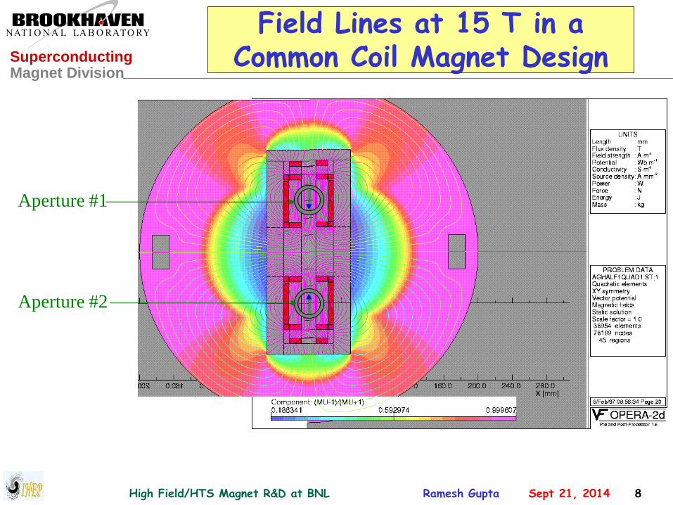
Field Lines at 15 T in a Common Coil Magnet Design
Aperture #1
Aperture #2
High Field/HTS Magnet R&D at BNL Ramesh Gupta Sept 21, 2014 9
Superconducting Magnet Division
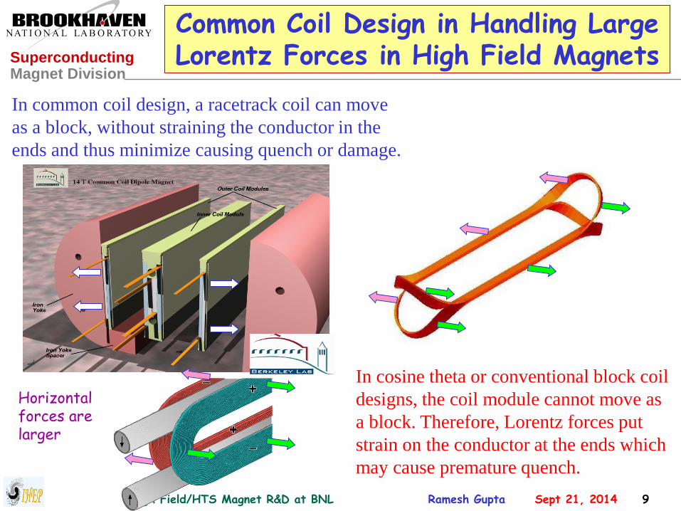
Common Coil Design in Handling Large Lorentz Forces in High Field Magnets
In common coil design, a racetrack coil can move
as a block, without straining the conductor in the
ends and thus minimize causing quench or damage.
Horizontal forces are larger
In cosine theta or conventional block coil
designs, the coil module cannot move as
a block. Therefore, Lorentz forces put
strain on the conductor at the ends which
may cause premature quench.

High Field/HTS Magnet R&D at BNL Ramesh Gupta Sept 21, 2014 10
Superconducting Magnet Division
Possible Layout of Common Coil Designs
Internal
Support
Module Collar Module
Coil
Modules HTS
Coil
R&D Magnet 15 T Field Quality Magnet
15 T design is
based on Nb3Sn
conductor with
Jc = 2200 A/mm2
@(12T, 4.2K)
Vary aperture after the coils are made
• a unique feature in R&D magnets
• lower separation, higher field
A good field
quality
magnetic
design is
demonstrated
More horizontal
space for structure
will need a minor
iteration

High Field/HTS Magnet R&D at BNL Ramesh Gupta Sept 21, 2014 11
Superconducting Magnet Division
Demonstration of a Good Field Quality in Geometric Harmonics
Normal Harmonics at 10 mm in the units of 10-4
-1.0
-0.8
-0.6
-0.4
-0.2
0.0
0.2
0.4
0.6
0.8
1.0
0 2 4 6 8 10 12 14
(from 1/4 model)
Typical Requirements:
~ part in 104, we have part in 105
MAIN FIELD: -1.86463 (IRON AND AIR):
b 1: 10000.000 b 2: 0.00000 b 3: 0.00308
b 4: 0.00000 b 5: 0.00075 b 6: 0.00000
b 7: -0.00099 b 8: 0.00000 b 9: -0.01684
b10: 0.00000 b11: -0.11428 b12: 0.00000
b13: 0.00932 b14: 0.00000 b15: 0.00140
b16: 0.00000 b17: -0.00049 b18: 0.00000
Horizontal coil aperture:
40 mm
High Field/HTS Magnet R&D at BNL Ramesh Gupta Sept 21, 2014 12
Superconducting Magnet Division
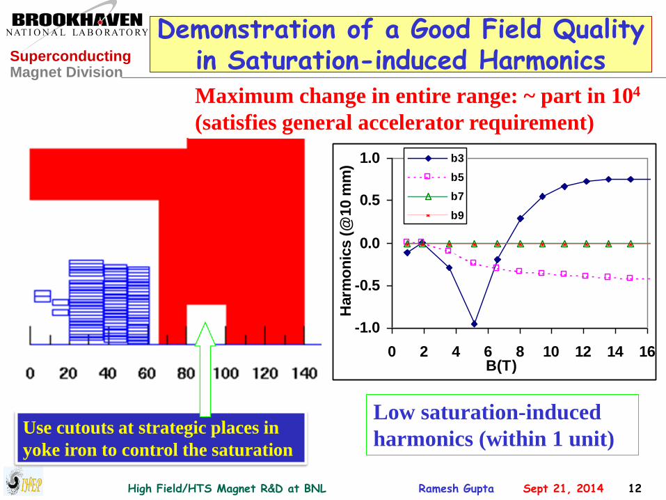
Demonstration of a Good Field Quality in Saturation-induced Harmonics
-1.0
-0.5
0.0
0.5
1.0
0 2 4 6 8 10 12 14 16B(T)
Harm
on
ics (
@10 m
m)
b3
b5
b7
b9
Low saturation-induced
harmonics (within 1 unit) Use cutouts at strategic places in
yoke iron to control the saturation
Maximum change in entire range: ~ part in 104
(satisfies general accelerator requirement)

High Field/HTS Magnet R&D at BNL Ramesh Gupta Sept 21, 2014 13
Superconducting Magnet Division
Demonstration of a Good Field Quality in End Harmonics
n Bn An
2 0.00 0.00
3 0.01 0.00
4 0.00 -0.03
5 0.13 0.00
6 0.00 -0.10
7 0.17 0.00
8 0.00 -0.05
9 0.00 0.00
10 0.00 -0.01
11 -0.01 0.00
12 0.00 0.00
13 0.00 0.00
14 0.00 0.00
15 0.00 0.00
16 0.00 0.00
17 0.00 0.00
18 0.00 0.00
End harmonics in Unit-m
Contribution to integral (an,bn) in a 14 m long dipole (<10-6) End harmonics can be made small in a common coil design.
-0.020-0.015-0.010-0.0050.0000.0050.0100.0150.0200.0250.030
0 2 4 6 8 10 12 14 16
Harmonic Number (a2:skew quad)
Delt
a-I
nte
gra
l bn
an
n bn an
2 0.000 0.001
3 0.002 0.000
4 0.000 -0.005
5 0.019 0.000
6 0.000 -0.014
7 0.025 0.000
8 0.000 -0.008
9 -0.001 0.000
10 0.000 -0.001
11 -0.001 0.000
12 0.000 0.000
(Very small)

High Field/HTS Magnet R&D at BNL Ramesh Gupta Sept 21, 2014 14
Superconducting Magnet Division
New Analytical Tool for Optimizing Common Coil Design
ASC2014
50 mm, 15 T Nb3Sn
design for IHEP
High Field/HTS Magnet R&D at BNL Ramesh Gupta Sept 21, 2014 15
Superconducting Magnet Division
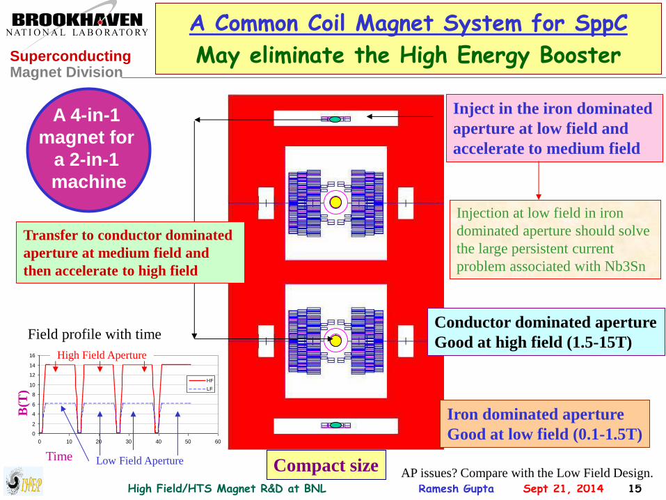
A Common Coil Magnet System for SppC
May eliminate the High Energy Booster
Inject in the iron dominated
aperture at low field and
accelerate to medium field
Transfer to conductor dominated
aperture at medium field and
then accelerate to high field
Iron dominated aperture
Good at low field (0.1-1.5T)
Conductor dominated aperture
Good at high field (1.5-15T)
Compact size
A 4-in-1
magnet for
a 2-in-1
machine
0
2
4
6
8
10
12
14
16
0 10 20 30 40 50 60
HF
LF
High Field Aperture
Low Field Aperture
B(T
)
Time
AP issues? Compare with the Low Field Design.
Injection at low field in iron
dominated aperture should solve
the large persistent current
problem associated with Nb3Sn
Field profile with time

High Field/HTS Magnet R&D at BNL Ramesh Gupta Sept 21, 2014 16
Superconducting Magnet Division
Common Coil Magnet System (Estimated cost savings by eliminating HEB)
SSC: 20+20 TeV;
SppC: 50+50 TeV
2 TeV HEB Cost in SSC (derived):
$700-800 million
Estimated for 5 TeV (5-50 TeV vlhc):
~$1,500 million (in 1990 US$)
Cost savings in equivalent 2040 $?
Based on 1990 cost in US$
Cost Distribution of Major Systems(Reference SSC Cost: 1990 US $7,837 million)
Other Accl.
& Facilities
23.3%Main
Collider
56.7%
HEB
9.3%
Experi-
ments
10.7%
(Derived based on certain assumptions)
A part of this saving (say ~20-30%) may be
used towards two extra apertures, etc. in
main tunnel. Estimated savings ~ $1 billion.

High Field/HTS Magnet R&D at BNL Ramesh Gupta Sept 21, 2014 17
Superconducting Magnet Division
Possibility of a Combined Function Common Coil Magnet Design
In a conventional superconducting magnet design, the right side of
the coil return on the left side. In a common coil magnet, the coil
does not return on the other side, it returns to other aperture.
• Thus in a common coil
magnet, the combined
function magnet design is
simpler as the coils on the
right and left sides could be
easily different.
Left side coil Right side coil
High Field/HTS Magnet R&D at BNL Ramesh Gupta Sept 21, 2014 18
Superconducting Magnet Division
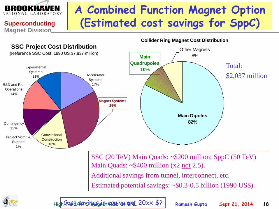
A Combined Function Magnet Option (Estimated cost savings for SppC)
Collider Ring Magnet Cost Distribution
Main Dipoles
82%
Main
Quadrupoles
10%
Other Magnets
8%
SSC (20 TeV) Main Quads: ~$200 million; SppC (50 TeV)
Main Quads: ~$400 million (x2 not 2.5).
Additional savings from tunnel, interconnect, etc.
Estimated potential savings: ~$0.3-0.5 billion (1990 US$).
Cost savings in equivalent 20xx $?
Total:
$2,037 million
SSC Project Cost Distribution (Reference SSC Cost: 1990 US $7,837 million)
Contingency
12%
Magnet Systems
29%
R&D and Pre-
Operations
14%
Experimental
Systems
11% Accelerator
Systems
17%
Conventional
Construction
16%
Project Mgmt. &
Support
1%

High Field/HTS Magnet R&D at BNL Ramesh Gupta Sept 21, 2014 19
Superconducting Magnet Division
React & Wind Nb3Sn Common Coil Dipole
http://www.bnl.gov/magnets/staff/gupta/
R. Gupta, M. Anerella, J. Cozzolino, J. Escallier,
G. Ganetis, A. Ghosh, M. Harrison, J. Muratore,
W. Sampson and P. Wanderer
Presented by Ramesh Gupta
@ ASC 2006
(also included react & wind Bi2212 HTS)

High Field/HTS Magnet R&D at BNL Ramesh Gupta Sept 21, 2014 20
Superconducting Magnet Division
Special Consideration for Nb3Sn Magnets
High temperature (~650o C) reaction is required to turn Nb-Sn mixture in to Nb3Sn
A15 phase which becomes superconducting at low temperatures.
Nb3Sn is brittle after this high temperature reaction. Moreover, during the reaction,
Nb-Sn expands and contracts while becoming sensitive to strain.
Two distinct approaches for making Nb3Sn magnets:
1. Wind & React
First wind the coil and then react the entire coil package.
First “good news” then “bad news”!
2. React & Wind
First react the conductor and then wind the coil.
First “bad news” then “good news”!

High Field/HTS Magnet R&D at BNL Ramesh Gupta Sept 21, 2014 21
Superconducting Magnet Division
A Few Advantages of React & Wind Approach
• In the “React & Wind” approach the coil and associated structure is
not subjected to the high temperature reaction. This allows one to use
a variety of insulation and other materials in coil modules.
» In “Wind & React”, one is limited in choosing insulating material,
etc. since the entire coil package goes through reaction.
• The “React & Wind” approach appears to be more adaptable for
building production magnets in industry by extending most present
techniques. Once the proper tooling is developed and the cable is
reacted, most remaining steps in industrial production of magnets
remain nearly the same in both Nb-Ti and Nb3Sn magnets.
• Since no specific component of “React & Wind” approach appears
to be length dependent, demonstration of a particular design and/or
technique in a short magnet, should be applicable in long production
magnet (except for mechanical, quench protection, etc.).

High Field/HTS Magnet R&D at BNL Ramesh Gupta Sept 21, 2014 22
Superconducting Magnet Division
Basic Features of BNL Nb3Sn 10+ T React & Wind Common Coil Dipole
• Two layer, 2-in-1 common coil design
• 10.2 T bore field, 10.7 T peak field at 10.8
kA short sample current
• 31 mm horizontal aperture
• Large (338 mm) vertical aperture
» A unique feature for coil testing
• Dynamic grading by electrical shunt
• 0.8 mm, 30 strand Rutherford cable
• 70 mm minimum bend radius
• 620 mm overall coil length
• Coil wound on magnetic steel bobbin
• One spacer in body and one in ends
• Iron over ends
• Iron bobbin
• Stored Energy@Quench ~0.2 MJ

High Field/HTS Magnet R&D at BNL Ramesh Gupta Sept 21, 2014 23
Superconducting Magnet Division
Mechanical Design Features
Main components of support structure:
• Stainless steel collar: 13 mm thick
• Rigid yoke: 534 mm o.d.
• Stainless steel shell : 25 mm thick
• End plate: 127 mm thick
• Magnet is designed for almost no cold
pre-stress (horizontal, vertical or axial)
• Small warm vertical load is applied to
account for differential thermal expansion
• Inflatable bladder to keep coil outward
• Keepers (SS) to lock coil to collars
• End plates (SS) were circumferentially
welded to shell
The original support structure was
designed for 40 mm, 12.5 T dipole.
Choice of conductor, etc. made it 31
mm, 10.2 T dipole.

High Field/HTS Magnet R&D at BNL Ramesh Gupta Sept 21, 2014 24
Superconducting Magnet Division
Nb3Sn High Temperature Reaction
Used for reacting long
lengths of Nb3Sn cable
Oil impregnation puts a thin coating on
wires of Rutherford cable to avoid
sintering during the reaction
Oil Impregnation Setup Large (1.5 m3) reaction furnace
Cable was pre-annealed to take out
initial thermal expansion and to avoid
possible local strain during high
temperature reaction.

High Field/HTS Magnet R&D at BNL Ramesh Gupta Sept 21, 2014 25
Superconducting Magnet Division
Automatic Coil Winder : A Key Component in Developing “React & Wind” Technology
Each part and step in this new automatic coil winder is carefully designed to
minimize the potential of bending degradation to brittle superconductors
during the winding process. The machine is fully automated and computer
controlled to minimize uncontrolled errors (human handling). All steps are
recorded to carefully debug the process, as and if required.

High Field/HTS Magnet R&D at BNL Ramesh Gupta Sept 21, 2014 26
Superconducting Magnet Division
BNL Nb3Sn React & Wind Common Coil Dipole DCC017 During Final Assembly

High Field/HTS Magnet R&D at BNL Ramesh Gupta Sept 21, 2014 27
Superconducting Magnet Division
Quench Plot of BNL React & Wind Common Coil Dipole DCC017
5000
6000
7000
8000
9000
10000
11000
0 10 20 30 40 50 60 70
Quench Number
Qu
en
ch
Cu
rre
nt
(A)
COIL 32
COIL 33
COIL 34
COIL 35
Level-no quench
Short Sample with bending strain
THERMAL CYCLE
2550 100 200
Ramp rates, A/s
10 25
Computed Short Sample
• Magnet reached short sample after a number of quenches
Reasonable for the first technology magnet
• No significant ramp rate dependence
Ic=10.8 kA
Bpk=10.7 T
Bss=10.2 T

High Field/HTS Magnet R&D at BNL Ramesh Gupta Sept 21, 2014 28
Superconducting Magnet Division
Load-line and Peak Field Line with Extracted Strand Measurements
8.0
8.5
9.0
9.5
10.0
10.5
11.0
11.5
12.0
8.0 8.5 9.0 9.5 10.0 10.5 11.0 11.5 12.0
Current (kA)
Fie
ld (
T)
B0
Bpk
Coil 32 Ic
• Magnet reached short sample based on the
measurements of the extracted strand of the
two types of cables used in coils.
• Magnet did not have any energy extraction
system. There was a concern if there could
be strain degradation due to thermo-
mechanical effects. No conclusive evidence
based on limited information.
• Magnet had practically no pre-stress on the
coil (horizontal, vertical or axial). No
experiment are planned to determine if pre-
stress could improve the performance.
• Relative (internal) deflections of coils
could have been ~100 mm. Absolute
deflections much higher (~a factor of two).

High Field/HTS Magnet R&D at BNL Ramesh Gupta Sept 21, 2014 29
Superconducting Magnet Division
HTS Magnet R&D in a Common Coil Hybrid Design
• Perfect for R&D magnets now.
HTS is subjected to the similar
forces that would be present in an all
HTS magnet. Therefore, several
technical issues will be addressed.
• Also a good design for specialty
magnets where the performance, not
the cost is an issue. Also future
possibilities for main dipoles.
• Field in outer layers is ~2/3 of that in
the 1st layer. Use HTS in the 1st layer
(high field region) and LTS in the
other layers (low field regions).
HTS COILS
LTS COILS
High Field/HTS Magnet R&D at BNL Ramesh Gupta Sept 21, 2014 30
Superconducting Magnet Division
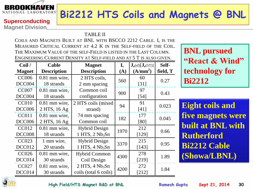
Bi2212 HTS Coils and Magnets @ BNL
TABLE II
COILS AND MAGNETS BUILT AT BNL WITH BSCCO 2212 CABLE. Ic IS THE
MEASURED CRITICAL CURRENT AT 4.2 K IN THE SELF-FIELD OF THE COIL.
THE MAXIMUM VALUE OF THE SELF-FIELD IS LISTED IN THE LAST COLUMN.
ENGINEERING CURRENT DENSITY AT SELF-FIELD AND AT 5 T IS ALSO GIVEN.
Coil /
Magnet
Cable
Description
Magnet
Description
Ic
(A)
Je(sf)[Je(5T)]
(A/mm2)
Self-
field, T
CC006
DCC004
0.81 mm wire,
18 strands560
60
[31]0.27
CC007
DCC004
0.81 mm wire,
18 strands
2 HTS coils,
2 mm spacing
Common coil
configuration900
97
[54]0.43
CC010
DCC006
0.81 mm wire,
2 HTS, 16 Ag94
91
[41]0.023
CC011
DCC006
0.81 mm wire,
2 HTS, 16 Ag
2 HTS coils (mixed
strand)
74 mm spacing
Common coil182
177
[80]0.045
CC012
DCC008
0.81 mm wire,
18 strands
Hybrid Design
1 HTS, 2 Nb3Sn1970
212
[129]0.66
CC023
DCC012
1 mm wire,
20 strands
Hybrid Design
1 HTS, 4 Nb3Sn3370
215
[143]0.95
CC026
DCC014
0.81 mm wire,
30 strands4300
278
[219]1.89
CC027
DCC014
0.81 mm wire,
30 strands
Hybrid Common
Coil Design
2 HTS, 4 Nb3Sn
coils (total 6 coils)4200
272
[212]1.84
Eight coils and
five magnets were
built at BNL with
Rutherford
Bi2212 Cable
(Showa/LBNL)
BNL pursued
“React & Wind”
technology for
Bi2212

High Field/HTS Magnet R&D at BNL Ramesh Gupta Sept 21, 2014 31
Superconducting Magnet Division
Magnet Structures for Bi-2212
Com
mon C
oil
Des
ign
High Field/HTS Magnet R&D at BNL Ramesh Gupta Sept 21, 2014 32
Superconducting Magnet Division
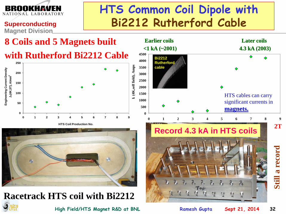
HTS Common Coil Dipole with Bi2212 Rutherford Cable
8 Coils and 5 Magnets built
with Rutherford Bi2212 Cable
Racetrack HTS coil with Bi2212
0
500
1000
1500
2000
2500
3000
3500
4000
4500
0 1 2 3 4 5 6 7 8 9
HTS Coil Production No.
I c (
4K
,sel
f fi
eld
), A
mp
s
Ic
HTS cables can carry
significant currents in
magnet coils.
Earlier coils
<1 kA (~2001)
Later coils
4.3 kA (2003)
0
500
1000
1500
2000
2500
3000
3500
4000
4500
0 1 2 3 4 5 6 7 8 9
HTS Coil Production No.
I c (
4K
,sel
f fi
eld
), A
mp
s
Ic
HTS cables can carry
significant currents in
magnets.
Earlier coils
<1 kA (~2001)
Later coils
4.3 kA (2003)
Bi2212
Rutherford
cable
Bi2212
Rutherford
cable
Record 4.3 kA in HTS coils2T
0
50
100
150
200
250
0 1 2 3 4 5 6 7 8 9
HTS Coil Production No.
En
gin
ee
rin
g C
urr
en
t D
en
sit
y
Je(4
K,5
T),
A/m
m2
Sti
ll a
rec
ord

High Field/HTS Magnet R&D at BNL Ramesh Gupta Sept 21, 2014 33
Superconducting Magnet Division
Unique Coil Test Features
A unique feature of this design is a large vertical open space for high field
testing of racetrack HTS insert coils without disassembling the magnet.
HTS insert coil test configuration
(HTS/Nb3Sn Hybrid magnet)
HTS Coil
HTS coil made with Rutherford cable from Showa/LBL
HTS coils made with BSCCO tape from ASC

High Field/HTS Magnet R&D at BNL Ramesh Gupta Sept 21, 2014 34
Superconducting Magnet Division
Conclusions from BNL Experience of React & Wind Common Coil Dipole
• “React & Wind” is an appealing alternate option for building long
length high field Nb3Sn production magnet.
• Successful construction and test of the BNL common coil magnet
proves that, “React & Wind is a viable technology for high
field Nb3Sn accelerator magnets”.
• It should be possible to make React & Wind magnets up to ~15 T.
• Due to a unique large open space, this magnet can be used for
inexpensive and fast turn around high field HTS insert coil tests

High Field/HTS Magnet R&D at BNL Ramesh Gupta Sept 21, 2014 35
Superconducting Magnet Division
http://www.bnl.gov/magnets/staff/gupta
Open Midplane Dipole

High Field/HTS Magnet R&D at BNL Ramesh Gupta Sept 21, 2014 36
Superconducting Magnet Division
Open Midplane Dipole for FCC (as championed by Bob Palmer)
Courtesy: Bob Palmer, BNL

High Field/HTS Magnet R&D at BNL Ramesh Gupta Sept 21, 2014 37
Superconducting Magnet Division
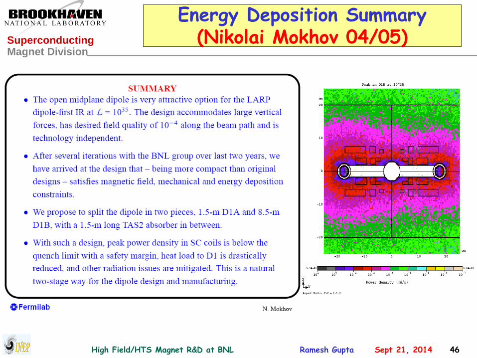
An Ideal Open Midplane Design
• Decay particles will, therefore, deposit energy in a
warm absorber that is sufficiently away from the
superconducting coils or support structure.
• In a partial “open midplane design”, although there
is “no conductor” at the midplane, there could be
some “other structure” between the upper and lower
halves of the coil to help deal with Lorentz forces.
• Those designs, though significantly reduce energy
deposited in coils from direct hit, could still face heat
from secondary showers produced by the other
structure. In addition, the energy deposition in that
cold structure itself could be significant.
• Therefore, an “ideal” or “true” open midplane dipole
should be preferred, if a viable design can be proven.
An ideal open midplane design will have no structure on the axis

High Field/HTS Magnet R&D at BNL Ramesh Gupta Sept 21, 2014 38
Superconducting Magnet Division
Challenges associated with the “Ideal” or “True” Open Midplane Dipole Design
#1 In usual cosine theta or block coil designs, there are large
attractive forces between upper and lower coils. How can
these coils hang in air with no structure in between?
#2 The ratio of peak field in the coil to the design field
appears to become large for large midplane gaps.
#3 The large gap at midplane appears to make obtaining
good field quality a challenging task. Gap requirements
are such that a significant portion of the cosine theta,
which normally plays a major role in generating field and
field quality, must be taken out from the coil structure.
Several innovative solutions were developed to
overcome above challenges (at least theoretically) with a
significant funding from LARP. However, the funding was
terminated before those solutions could be proven.
High Field/HTS Magnet R&D at BNL Ramesh Gupta Sept 21, 2014 39
Superconducting Magnet Division
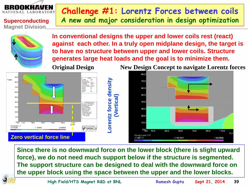
Challenge #1: Lorentz Forces between coils A new and major consideration in design optimization
Since there is no downward force on the lower block (there is slight upward
force), we do not need much support below if the structure is segmented.
The support structure can be designed to deal with the downward force on
the upper block using the space between the upper and the lower blocks.
In conventional designs the upper and lower coils rest (react)
against each other. In a truly open midplane design, the target is
to have no structure between upper and lower coils. Structure
generates large heat loads and the goal is to minimize them.
Zero vertical force line
Lo
ren
tz f
orc
e d
en
sit
y
(Vert
ical)
Original Design New Design Concept to navigate Lorentz forces

High Field/HTS Magnet R&D at BNL Ramesh Gupta Sept 21, 2014 40
Superconducting Magnet Division
Vertical Forces at 15 T (design optimized to first order)
Net upward vertical force on
lower double pancake coil
Downward vertical force on upper double
pancake coil is taken by the support structure
between two double pancake coils
Net Force per quadrant:
Horizontal = 11 MN/m; Vertical –5.4 MN/m

High Field/HTS Magnet R&D at BNL Ramesh Gupta Sept 21, 2014 41
Superconducting Magnet Division
Mechanical Analysis (J. Schmalzle)
Above deflections are at design field (13.6 T). They are ~1-2 mil higher at 15 T.
In a more optimized design the relative values of the x and y deflections
are 3-4 mil (100 micron) and the maximum value is 6-7 mil (170 micron)
Y-deflections X-deflections

High Field/HTS Magnet R&D at BNL Ramesh Gupta Sept 21, 2014 42
Superconducting Magnet Division
Challenge #2: Peak Field
Quench Field: ~16 T with Jc = 3000 A/mm2, Cu/Non-cu = 0.85
Quench Field: ~15.8 T with Jc = 3000 A/mm2, Cu/Non-cu = 1.0
Several designs have been optimized with a small peak enhancement: ~7% over Bo
Relative field
enhancement in coil
(peak field) over the
central field
Similar to that in an
optimized cosine
theta designs
High Field/HTS Magnet R&D at BNL Ramesh Gupta Sept 21, 2014 43
Superconducting Magnet Division
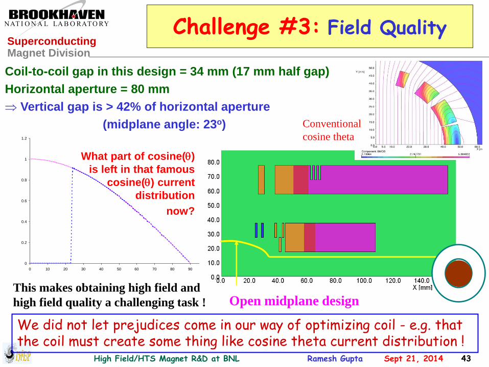
Challenge #3: Field Quality
Coil-to-coil gap in this design = 34 mm (17 mm half gap)
Horizontal aperture = 80 mm
Vertical gap is > 42% of horizontal aperture
(midplane angle: 23o)
Open midplane design
0
0.2
0.4
0.6
0.8
1
1.2
0 10 20 30 40 50 60 70 80 90 100
What part of cosine()
is left in that famous
cosine() current
distribution
now?
We did not let prejudices come in our way of optimizing coil - e.g. that the coil must create some thing like cosine theta current distribution !
This makes obtaining high field and
high field quality a challenging task !
Conventional
cosine theta
High Field/HTS Magnet R&D at BNL Ramesh Gupta Sept 21, 2014 44
Superconducting Magnet Division
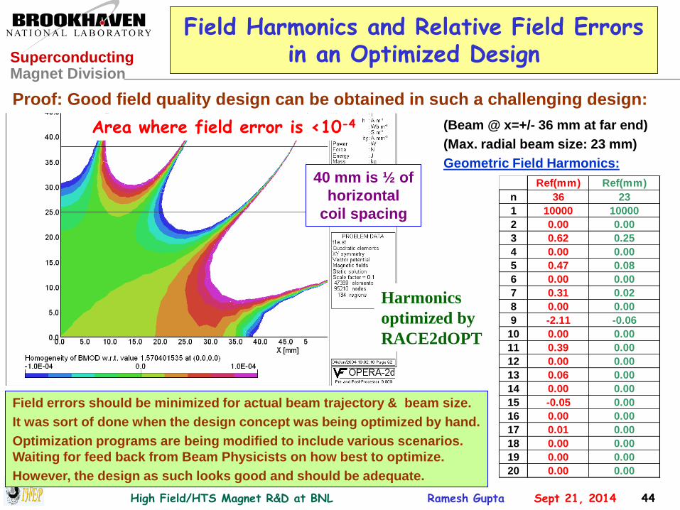
Field Harmonics and Relative Field Errors in an Optimized Design
Ref(mm) Ref(mm)
n 36 23
1 10000 10000
2 0.00 0.00
3 0.62 0.25
4 0.00 0.00
5 0.47 0.08
6 0.00 0.00
7 0.31 0.02
8 0.00 0.00
9 -2.11 -0.06
10 0.00 0.00
11 0.39 0.00
12 0.00 0.00
13 0.06 0.00
14 0.00 0.00
15 -0.05 0.00
16 0.00 0.00
17 0.01 0.00
18 0.00 0.00
19 0.00 0.00
20 0.00 0.00
Proof: Good field quality design can be obtained in such a challenging design:
(Beam @ x=+/- 36 mm at far end)
(Max. radial beam size: 23 mm)
Geometric Field Harmonics:
Area where field error is <10-4
Field errors should be minimized for actual beam trajectory & beam size.
It was sort of done when the design concept was being optimized by hand.
Optimization programs are being modified to include various scenarios.
Waiting for feed back from Beam Physicists on how best to optimize.
However, the design as such looks good and should be adequate.
40 mm is ½ of
horizontal
coil spacing
Harmonics
optimized by
RACE2dOPT

High Field/HTS Magnet R&D at BNL Ramesh Gupta Sept 21, 2014 45
Superconducting Magnet Division
Field Uniformity in an Optimized 15 T Open Midplane Dipole Design
The maximum horizontal
displacement of the
beam at the far end of IP
is +/- 36 mm.
The actual field errors in
these magnets will now
be determined by
construction, persistent
currents, etc.; i.e., they
are not limited by the
design geometry.
Proof that good field quality can be obtained in such a
wide open midplane dipole design:
Note:
The scale is a few parts in 10-5.
Rel
ati
ve
Fie
ld E
rrors
High Field/HTS Magnet R&D at BNL Ramesh Gupta Sept 21, 2014 46
Superconducting Magnet Division
Energy Deposition Summary (Nikolai Mokhov 04/05)

High Field/HTS Magnet R&D at BNL Ramesh Gupta Sept 21, 2014 47
Superconducting Magnet Division
Summary of Optimized Open Midplane Nb3Sn Dipole Designs for LARP
A B C D E F
H(mm) 84 135 160 120 80 120
V(mm) 33 20 50 30 34 40
V/H 0.39 0.15 0.31 0.25 0.43 0.33
Bo(T) 13.6 13.6 13.6 13.6 15 13.6
Bss(T) 15 15 15 14.5 16 15
Jc(A/mm2) 2500 3000 3000 3000 3000 3000
Cu/Sc 1 1,1.8 0.85 0.85 0.85 1
A(cm2) 161 198 215 148 151 125
Ri(mm) 135 400 400 320 300 300
Ro(mm) 470 800 1000 700 700 700
E(MJ/m) 2.2 4.8 9.2 5.2 4.1 4.8
Fx(MN/m) 9.6 10.1 12.3 9.5 10.4 9.6
Fy(MN/m) -3.0 -6.8 -8.7 -7.0 -5.1 -5.4
For more information (publications + talks): http://www.bnl.gov/magnets/Staff/Gupta/
High Field/HTS Magnet R&D at BNL Ramesh Gupta Sept 21, 2014 48
Superconducting Magnet Division
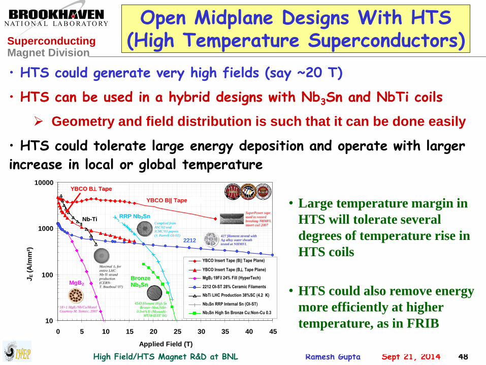
Open Midplane Designs With HTS (High Temperature Superconductors)
• HTS could generate very high fields (say ~20 T)
• HTS can be used in a hybrid designs with Nb3Sn and NbTi coils
Geometry and field distribution is such that it can be done easily
• HTS could tolerate large energy deposition and operate with larger
increase in local or global temperature
10
100
1000
10000
0 5 10 15 20 25 30 35 40 45
Applied Field (T)
JE (
A/m
m²)
YBCO Insert Tape (B|| Tape Plane) YBCO Insert Tape (B Tape Plane) MgB2 19Fil 24% Fill (HyperTech) 2212 OI-ST 28% Ceramic Filaments NbTi LHC Production 38%SC (4.2 K) Nb3Sn RRP Internal Sn (OI-ST) Nb3Sn High Sn Bronze Cu:Non-Cu 0.3
YBCO B|| Tape Plane
YYBBCCOO BB TTaappee
PPllaannee
2212
RRRRPP NNbb33SSnn
BBrroonnzzee
NNbb33SSnn MgB2
NNbb--TTii SSuuppeerrPPoowweerr ttaappee
uusseedd iinn rreeccoorrdd
bbrreeaakkiinngg NNHHMMFFLL
iinnsseerrtt ccooiill 22000077
1188++11 MMggBB22//NNbb//CCuu//MMoonneell
CCoouurrtteessyy MM.. TToommssiicc,, 22000077
427 filament strand with
Ag alloy outer sheath
tested at NHMFL
Maximal JE for
entire LHC
NbTi strand
production
(CERN-
T. Boutboul '07)
CCoommpplliieedd ffrroomm
AASSCC''0022 aanndd
IICCMMCC''0033 ppaappeerrss
((JJ.. PPaarrrreellll OOII--SSTT))
44554433 ffiillaammeenntt HHiigghh SSnn
BBrroonnzzee--1166wwtt..%%SSnn--
00..33wwtt%%TTii ((MMiiyyaazzaakkii--
MMTT1188--IIEEEEEE’’0044))
• Large temperature margin in
HTS will tolerate several
degrees of temperature rise in
HTS coils
• HTS could also remove energy
more efficiently at higher
temperature, as in FRIB

High Field/HTS Magnet R&D at BNL Ramesh Gupta Sept 21, 2014 49
Superconducting Magnet Division
Common Coil Open Midplane Dipole?
How about common coil
open midplane dipole?
Can one tolerate some
perturbation in a small
region in the ends where
turns must go from one
aperture to another?

High Field/HTS Magnet R&D at BNL Ramesh Gupta Sept 21, 2014 50
Superconducting Magnet Division
Other HTS Magnet R&D
Programs at BNL
(select cases)

High Field/HTS Magnet R&D at BNL Ramesh Gupta Sept 21, 2014 51
Superconducting Magnet Division
HTS Magnet Program at BNL
• HTS magnet R&D over a wide range:
– High field, Medium field and low field (high temperature)
– Many geometries – racetrack, cosine theta, solenoid
• Number of HTS coils/magnets designed built & tested:
– Well over 100 HTS coils and well over 10 HTS magnets
• Type of HTS used:
– Bi2223, Bi2212, ReBCO, MgB2 – wire, cable, tape
• Amount of HTS acquired:
– ~50 km (4 mm tape equivalent)
• Our recent activities have been largely on magnets with ReBCO
– (yet one Bi2223 and one MgB2 magnet is ready for testing)

High Field/HTS Magnet R&D at BNL Ramesh Gupta Sept 21, 2014 52
Superconducting Magnet Division
High Field (16T) Demo of HTS Magnet
Field on axis: 15.7 T
Field on coil : 16.2 T
(original target: 10-12T)
Highest field all HTS solenoid
Overall Jo in coil:
>500 A/mm2 @16 T
Insert solenoid: 14 pancakes, 25 mm aperture
PBL/BNL SBIR

High Field/HTS Magnet R&D at BNL Ramesh Gupta Sept 21, 2014 53
Superconducting Magnet Division
Large Aperture High Field HTS Magnet
0
25
50
75
100
125
150
175
200
225
250
275
300
0 5 10 15 20 25 30 35 40 45 50 55 60 65 70 75 80
Cu
rre
nt
(A)
Temp(K)
Peak Field on Coil at 250 A : ~9.2 T
Coil operated with margin at 250 A
PBL/BNL 100 mm HTS Solenoid Test for Muon Collider
Half midsert operated at 250 A @4 K
(6.4 T field on axis, 9.2 T peak field on coil
Design value for full midsert: 220 A for 10 T
Half midsert (12 pancakes)
Full midsert (24 pancakes)
Run stopped at 250 A

High Field/HTS Magnet R&D at BNL Ramesh Gupta Sept 21, 2014 54
Superconducting Magnet Division
Superconducting Magnetic Energy Storage (SMES)
High field large aperture HTS solenoid with huge stresses
Key Target Parameters: 25T, 100mm, 1.7MJ, 12mm ReBCO
Funded by arpa-e as a “high risk, high reward” project

High Field/HTS Magnet R&D at BNL Ramesh Gupta Sept 21, 2014 55
Superconducting Magnet Division
SMES Magnet
Inner Coil
(28 pancakes)
Outer Coil
(16 pancakes)

High Field/HTS Magnet R&D at BNL Ramesh Gupta Sept 21, 2014 56
Superconducting Magnet Division
2 pancakes 1140 A, 4K
HTS SMES Magnet Test Results 100 mm bore ReBCO SMES Coil
46 pancakes 350 A, 27K, 12.5 T
Peak
fie
lds h
igh
er
12 pancakes 760 A, 4K, 11.4 T

High Field/HTS Magnet R&D at BNL Ramesh Gupta Sept 21, 2014 57
Superconducting Magnet Division
HTS Quadrupole for FRIB
(now part of baseline design)
FRIB: Facility for Rare Isotope Beams, now under construction at MSU, USA.

High Field/HTS Magnet R&D at BNL Ramesh Gupta Sept 21, 2014 58
Superconducting Magnet Division
Radiation Tolerant HTS Quad for the
Fragment Separator Region of FRIB
Exposure in the first magnet itself:
Head Load : ~10 kW/m, 15 kW
Fluence : 2.5 x10¹⁵ n/cm2 per year
Radiation : ~10 MGy/year
Pre-separator quads and dipole
To create intense rare isotopes, 400 kW beam hits the production target.
Magnets in the fragment separator region are exposed to unprecedented radiation
and heat loads. HTS can efficiently remove that at elevated temperatures.
Courtesy: Zeller, MSU
Radiation resistant
Co
urt
esy: A
l Z
elle
r, F
RIB
/MS
U

High Field/HTS Magnet R&D at BNL Ramesh Gupta Sept 21, 2014 59
Superconducting Magnet Division
6 feet
1.3 m
Warm Iron Design with Bi2223 HTS
First Generation HTS Quad for FRIB
Mirror Iron
Return YokeIron Pole
HTS Coils
in Structure
Mirror cold iron
Mirror warm iron

High Field/HTS Magnet R&D at BNL Ramesh Gupta Sept 21, 2014 60
Superconducting Magnet Division
First Generation HTS Quad Test (operation over a large temperature range)
0
50
100
150
200
250
300
0 10 20 30 40 50 60 70 80 90 100
Tempratue (K)
Cu
rren
t @
0.1
mV
/cm
(A
)
Two Coils
Four Coils
Six Coils
Twelve Coils

High Field/HTS Magnet R&D at BNL Ramesh Gupta Sept 21, 2014 61
Superconducting Magnet Division
Second Generation HTS Quad for FRIB Fragment Separator Region
Important: Magnet for a real machine- baseline design of FRIB
YBCO from two vendors
ASC and SuperPower

High Field/HTS Magnet R&D at BNL Ramesh Gupta Sept 21, 2014 62
Superconducting Magnet Division
Large Temperature Margins (only possible with HTS)
HTS provides robust operation against local and global heat loads
High Field/HTS Magnet R&D at BNL Ramesh Gupta Sept 21, 2014 63
Superconducting Magnet Division
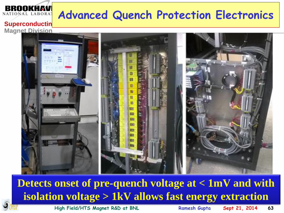
Advanced Quench Protection Electronics
Detects onset of pre-quench voltage at < 1mV and with
isolation voltage > 1kV allows fast energy extraction

High Field/HTS Magnet R&D at BNL Ramesh Gupta Sept 21, 2014 64
Superconducting Magnet Division
Protection of HTS Magnet During an Operational Accident Near Design Current
175A
185A Design: 210 A in SP Coils
Ringing in power supply
made situation worse
90mV

High Field/HTS Magnet R&D at BNL Ramesh Gupta Sept 21, 2014 65
Superconducting Magnet Division
A Warm bore Cryo-cooled Magnet with 6 HTS coils
Evening: Switch ON; Morning: COLD
Suitable for various studies
Quench studies
Measure magnetization
induced harmonics
as a function of time
as a function of
temperature
as a function of field

High Field/HTS Magnet R&D at BNL Ramesh Gupta Sept 21, 2014 66
Superconducting Magnet Division
Low Magnetic Field Application HTS Solenoid with Superconducting Cavity
for the Energy Recovery Linac (ERL) at BNL
HTS solenoid is placed in cold to warm transition
region after the superconducting cavity where
neither LTS or copper solenoid would work
Early focusing provides a unique and better technical solution

High Field/HTS Magnet R&D at BNL Ramesh Gupta Sept 21, 2014 67
Superconducting Magnet Division
HTS Cosine Theta R&D for Hadron Collider

High Field/HTS Magnet R&D at BNL Ramesh Gupta Sept 21, 2014 68
Superconducting Magnet Division
Cos () Coil - PBL/BNL STTR#1 (12 mm, one block, 77 K)
BENEFITS of Kapton-CI:
•No epoxy/adhesive to HTS tape
(prone to degradation by epoxy)
• Standard insulation in magnets
•Cured coil can be handled easily
•Makes good coil (including ends)
No measurable degradation@77 K

High Field/HTS Magnet R&D at BNL Ramesh Gupta Sept 21, 2014 69
Superconducting Magnet Division
Cos () Coil - PBL/BNL STTR#2 (4 mm, goal: full coil, 4 K test)
Future Plan (Phase I & Phase II)
No measurable degradation@77 K
• Construction and 4 K test of full
cos (θ) coil in next few months
• R&D to develop base technology
for accelerator magnets in next
few years (includes measuring
and finding ways to deal with
magnetization)
• Use these magnets in an
accelerator in next few decades

High Field/HTS Magnet R&D at BNL Ramesh Gupta Sept 21, 2014 70
Superconducting Magnet Division
SUMMARY and CONCLUSIONS
• This presentation summarized research activities at BNL that
are directly relevant to future circular colliders such as SppC.
• Common coil and open midplane magnet design are appealing as
they offer some unique and attractive technical solutions.
• Use of HTS is essential for magnets with design field of >16 T.
• A significant progress has been made in HTS magnet technology.
Given the time frame for building the next high energy collider,
HTS magnets should become a mature technology provided a
proper investment is made in R&D at this stage.
• There is a significant similarity between the IHEP and BNL on
how to carry out future magnet programs. A collaboration
between the two would be beneficial for developing technology.