RD-180 Engine Production and Flight...
14
AIAA-2004-3998 1 American Institute of Aeronautics and Astronautics RD-180 Engine Production and Flight Experience Boris I. Katorgin*, Vladimir K. Chvanov**, Felix J. Chelkis*** NPO Energomash, Khimki, Russia Michael Popp + , Lawrence G. Tanner ++ , Robert C. vanGiessen +++ , Scott J. Connally ++++ Pratt & Whitney Space Propulsion, West Palm Beach, Florida The RD-180 engine is a high performance, cost-effective booster engine with unique features, which enable Atlas launch vehicle growth, enhanced launch vehicle effectiveness and mission payload flexibility. The engine is a 900,000 lbf thrust, high specific impulse staged combustion cycle LOX/kerosene engine, which has been in production since 1998 for use on Atlas III and Atlas V launch vehicles. Production engines are being provided to Lockheed Martin by RD AMROSS, a 50/50 Pratt & Whitney / NPO Energomash Joint Venture company incorporated in the US. Current production engines are being built and acceptance tested by NPO Energomash in Russia, and are delivered to Lockheed Martin in Denver for vehicle integration. Engine acceptance processing, engine integration and launch support activities are conducted by joint NPO Energomash / Pratt & Whitney teams. To date, 23 engines have been delivered and 8 have been flown on missions from Cape Canaveral, with 100% mission success. I. Introduction In 1995, Lockheed Martin selected a NPO Energomash and Pratt & Whitney team to develop the RD-180 engine for use on its Atlas III and Atlas V launch vehicles. The engine was derived from the flight-proven NPO Energomash designed man-rated and reusable RD-170 engine. Its oxidizer rich staged combustion cycle and high chamber pressure make it the highest performance operational LOX/kerosene engine worldwide. Within four years after program start the engine development and certification for use on Atlas III was completed. The first production engine was delivered to Lockheed Martin in early 1999, and the first successful RD-180 powered Atlas launch took place on 24 May 2000, with the launch of an Atlas IIIA. Since then, the engine has also been certified for use on Atlas V which had its successful maiden launch on 21 August 2002. 40 th Joint Propulsion Conference Fort Lauderdale, Florida, July 11-14, 2004 __________________________________________________ * General Director and General Designer ** First Deputy General Director and General Designer *** Chief Designer + Program Manager, RD-180 Production and Flight Support, Associate Fellow, AIAA ++ Chief Engineer, RD-180 Engine Program +++ Senior Project Engineer, RD-180 Engine Program ++++ Cape Canaveral Site Representative, RD-180 Engine Program ____________________________________________ Copyright © 2004 by Pratt & Whitney. Published by the American Institute of Aeronautics and Astronautics, Inc., with permission. 40th AIAA/ASME/SAE/ASEE Joint Propulsion Conference and Exhibit 11 - 14 July 2004, Fort Lauderdale, Florida AIAA 2004-3998 Copyright © 2004 by Pratt & Whitney. Published by the American Institute of Aeronautics and Astronautics, Inc., with permission.
Transcript of RD-180 Engine Production and Flight...

AIAA-2004-3998
1 American Institute of Aeronautics and Astronautics
RD-180 Engine Production and Flight Experience
Boris I. Katorgin*, Vladimir K. Chvanov**, Felix J. Chelkis*** NPO Energomash, Khimki, Russia
Michael Popp+, Lawrence G. Tanner++, Robert C. vanGiessen+++, Scott J. Connally++++
Pratt & Whitney Space Propulsion, West Palm Beach, Florida
The RD-180 engine is a high performance, cost-effective booster engine with unique features, which enable Atlas launch vehicle growth, enhanced launch vehicle effectiveness and mission payload flexibility. The engine is a 900,000 lbf thrust, high specific impulse staged combustion cycle LOX/kerosene engine, which has been in production since 1998 for use on Atlas III and Atlas V launch vehicles. Production engines are being provided to Lockheed Martin by RD AMROSS, a 50/50 Pratt & Whitney / NPO Energomash Joint Venture company incorporated in the US. Current production engines are being built and acceptance tested by NPO Energomash in Russia, and are delivered to Lockheed Martin in Denver for vehicle integration. Engine acceptance processing, engine integration and launch support activities are conducted by joint NPO Energomash / Pratt & Whitney teams. To date, 23 engines have been delivered and 8 have been flown on missions from Cape Canaveral, with 100% mission success.
I. Introduction In 1995, Lockheed Martin selected a NPO Energomash and Pratt & Whitney team to develop the RD-180 engine for use on its Atlas III and Atlas V launch vehicles. The engine was derived from the flight-proven NPO Energomash designed man-rated and reusable RD-170 engine. Its oxidizer rich staged combustion cycle and high chamber pressure make it the highest performance operational LOX/kerosene engine worldwide. Within four years after program start the engine development and certification for use on Atlas III was completed. The first production engine was delivered to Lockheed Martin in early 1999, and the first successful RD-180 powered Atlas launch took place on 24 May 2000, with the launch of an Atlas IIIA. Since then, the engine has also been certified for use on Atlas V which had its successful maiden launch on 21 August 2002.
40th Joint Propulsion Conference Fort Lauderdale, Florida, July 11-14, 2004
__________________________________________________ * General Director and General Designer ** First Deputy General Director and General Designer *** Chief Designer + Program Manager, RD-180 Production and Flight Support, Associate Fellow, AIAA++ Chief Engineer, RD-180 Engine Program +++ Senior Project Engineer, RD-180 Engine Program ++++ Cape Canaveral Site Representative, RD-180 Engine Program
____________________________________________Copyright © 2004 by Pratt & Whitney. Published by the American Institute of Aeronautics and Astronautics, Inc., with permission.
40th AIAA/ASME/SAE/ASEE Joint Propulsion Conference and Exhibit11 - 14 July 2004, Fort Lauderdale, Florida
AIAA 2004-3998
Copyright © 2004 by Pratt & Whitney. Published by the American Institute of Aeronautics and Astronautics, Inc., with permission.

AIAA-2004-3998
2 American Institute of Aeronautics and Astronautics
Production engines are being provided to Lockheed Martin by RD AMROSS, a 50/50 Pratt & Whitney / NPO Energomash Joint Venture company incorporated in the US1. The RD-180 engine has been in production since 1998, with 23 engines delivered and 8 of those flown to date. Current production engines are being built and acceptance tested by NPO Energomash in Russia, and, upon completion of acceptance processing, are delivered to Lockheed Martin in Denver for vehicle integration. All launches to date have taken place from Cape Canaveral, however, preparations are currently under way to start launching Atlas V vehicles from Vandenberg in late 2005. Engine acceptance processing, engine integration and launch support activities are conducted by joint NPO Energomash / Pratt &Whitney teams. US production capabilities are being established at the present time, however, this paper will exclusively address production and use of Russian-produced engines.
The RD-180 engine enables Atlas launch vehicle growth by providing a cost-effective engine with the following unique features, which enhance the launch vehicle effectiveness:
· Smooth and continuous throttling from 47% power to 100% power · Atlas V booster engine interchangeability with Atlas III · Self-contained engine pneumatic system, 4 fewer fluid interfaces than with previous engine · Self-contained thrust vector control actuators; no auxiliary roll system required · Self-contained hydraulics after engine start · Reduced engine integration and checkout time, 12 days vs. 80 for previous engine · Possibility to use single engine in 2nd stage · Reduced engine cost
Figure 1 shows the Lockheed Martin Atlas launch vehicle family and the GTO payload capabilities for the
different Atlas III and Atlas V versions with RD-180. Figure 2 provides photographs of RD-180 powered Atlas III and Atlas V launches from Cape Canaveral. References 2-5 provide more detailed information on Lockheed Martin’s Atlas III and Atlas V launch vehicles. Mission payload flexibility for Atlas is also provided by the possibility to use either a single-engine or dual-engine Centaur upper stage, which is made possible due to the high thrust, high specific impulse and deep throttling capability of the RD-180 engine. It is the only engine with a throttle capability that is used aboard an expendable US launch vehicle, and it throttles without an appreciable loss of performance. Engine thrust settings are varied during booster ascent to minimize vehicle loads by throttling back during the maximum transonic loads and high dynamic pressure region of flight while otherwise maximizing vehicle performance. This throttling capability also provides a smoother and less stressful ride for the rocket and its satellite payload and allows for more efficient use of propellants. Figure 3 shows Atlas III and Atlas V boost phase engine thrust profiles.
Figure 1. Atlas Launch Vehicle Family Figure 2. Photographs of Atlas III and Atlas V
(Courtesy of Lockheed Martin Corporation) Launches from Cape Canaveral (Courtesy of Lockheed Martin Corporation)
Atlas Launch Vehicle Family by Lockheed Martin Astronautics
Atlas V(HLV)
Atlas V(500 Series)(0-5 SRBs)
Atlas IIAS Atlas III(SEC)
Atlas III(DEC)
Atlas IIAtlas IIA
12/91 12/93 5/00First Flight
Atlas V(400 Series)(0-3 SRBs)
2
6
10
14
18
22
26
30(k kg) (k lb) 21st Century Growth
SingleEngineCentaur
LoxTankStretch
RD-180Engine
SRBs
CommonCentaur
3.8mCommonCoreBooster
5m PLFGSO Kit
SRBs LiquidStrapons
1
3
5
7
9
11
13
GTO
Cap
abili
ty
2/02
RD-180
Atlas V(HLV)
Atlas V(500 Series)(0-5 SRBs)
Atlas IIAS Atlas III(SEC)
Atlas III(DEC)
Atlas IIAtlas IIA
12/91 12/93 5/00First Flight
Atlas V(400 Series)(0-3 SRBs)
2
6
10
14
18
22
26
30
2
6
10
14
18
22
26
30(k kg) (k lb) 21st Century Growth
SingleEngineCentaur
LoxTankStretch
RD-180Engine
SRBs
CommonCentaur
3.8mCommonCoreBooster
5m PLFGSO Kit
SRBs LiquidStrapons
1
3
5
7
9
11
13
GTO
Cap
abili
ty
2/02
RD-180 Atlas IIIA(AC-201)
Atlas V-401(AV-001)
Atlas V-521(AV-003)

AIAA-2004-3998
3 American Institute of Aeronautics and Astronautics
Figure 3. Atlas III and Atlas V Boost Phase Engine Thrust Profiles
The RD-180 engine will also be used in the Galaxy Express (GX) launch vehicle program6. This program is a joint activity between the Government of Japan and the Galaxy Express Corporation, a joint venture of Japanese and American corporations. The GX launch vehicle is a two-stage vehicle, with Lockheed Martin being responsible for the booster stage, and the Japanese industry team responsible for the upper stage, see Figure 4. Much of the GX Stage 1 hardware is very similar to that of Lockheed Martin’s Atlas III launch vehicle.
Figure 4. Galaxy Express (GX) Launch Vehicle with RD-180 Booster Propulsion (Courtesy of Lockheed Martin Corporation)
The current paper provides an RD-180 development background and engine description, followed by a description of the engine production at NPO Energomash in Russia and engine/vehicle integration and launch processing support activities. A summary of the RD-180 flight history is also included.
II. RD-180 Development Background and Engine Description Development of the RD-180 engine for use on Lockheed Martin launch vehicles was initiated in 1996 through a joint venture between Russia’s premier rocket engine enterprise, NPO Energomash (NPO EM) and Pratt & Whitney, a United Technologies Company. A streamlined development program was possible since the key technologies and full-scale combustion devices had been previously developed in Russia for the RD-170/171 family of engines used on the Energia-Buran and Zenit launch vehicles respectively. The RD-180 matured rapidly as a 2-chamber derivative of the 4-chamber RD-170/171 engines. It has 70% common hardware with the RD-170, and 30% is scaled from the RD-170. The development tasks centered around proving out the new turbomachinery, scaled for approximately 50% flow at 105% of the RD-170 pump discharge pressures. In addition, a more simple open-loop control system was provided which required new designs for the thrust control valve and the mixture ratio control valve. A newly designed engine-mounted fuel pre-valve was also provided to accommodate the necessary interface with the Atlas launch vehicles for engine start requirements. Figures 5 and 6 show a RD-180 engine schematic, and side views, respectively. Figure 7 shows a photograph of the first production engine during vehicle integration.
Japan’sSubsystem
Lockheed MartinSubsystemAtlas
LOx/RP-1Stage I
Payload Fairing
LOx/LNG Stage 2
RD-180Engine
Japan’sSubsystem
Lockheed MartinSubsystemAtlas
LOx/RP-1Stage I
Payload Fairing
LOx/LNG Stage 2
RD-180Engine
Atlas III vs. Atlas V Flight Thrust Profiles
0
10
20
30
40
50
60
70
80
90
100
0 50 100 150 200 250 300 350 400
Seconds
Pow
er L
evel
Atlas V MLVAtlas V HLVAtlas III

AIAA-2004-3998
4 American Institute of Aeronautics and Astronautics
Figure 5. RD-180 Engine Schematic Figure 6. RD-180 Engine
Using modified hardware from RD-170 engines, a demonstrator engine was quickly assembled to allow testing of the most significant new component, the main turbopump unit (MTU), which included the main LOX and main kerosene pumps on a single shaft, driven by a single stage turbine. Two such demonstrator engines, designated as DP-170, were assembled and tested between November 1996 and March 1997 for 12 tests and 1,610 seconds of run time, operated over a wide range of thrust and mixture ratio levels, and proved out the viability and performance of the scaled MTU designs over power levels and mission durations exceeding that required for Atlas III applications. The configuration was based on an RD-170 thrust frame, a 4-duct turbine hot gas collector manifold with two ducts capped, RD-170 LOX and kerosene boost pumps, modified RD-170 control system components, a single RD-170 preburner, (two are used on the RD-170/171 engines) and two main combustion chambers. Thus, the basic scheme of the RD-180 was tested in the existing test facilities for the RD-170 with very few changes to the engine interfaces required.
Following this highly successful test series, the first RD-180 engines were assembled for testing, and new
facility interfaces and adapters were designed and manufactured by NPO EM. These engines, for all intents and purposes, represented the flight configuration for use on Atlas III launch vehicles, and included new scaled boost pumps and thrust frame and the new valves mentioned previously. For development, 11 builds of 6 engines were tested 58 times for 8,986 seconds of runtime. The first engine of this series failed during its third hot fire test as a result of inappropriate scheduling of the new control valves during the start transient. Corrective action was identified and another test engine was under test in only 5 weeks. The third RD-180 to be tested was delivered to the Marshall Space Flight Center where 4 tests were conducted in a simulated Atlas III integrated test vehicle for 131 seconds, see Figure 8. These tests were limited in duration due to less than full size propellant run tanks, however, they were instrumental in proving out key launch vehicle interfaces and control system logic.
Figure 7. First RD-180 Production Engine Figure 8. RD-180 Engine Test at NASA during Vehicle Integration Marshall Space Flight Center
FuelInlet
HeatExchanger
LOX BoostPump
Fuel BoostPump
Fuel InletValve
FuelPump
LOXPump
Preburner
Turbine
ChamberMain Fuel
Valve
StartBottle
MixtureRatio Valve
ThrustControlValve
Main LOX Valve
HypergolicStart
Ampoule
Hot GasBellows
LOXInlet
FuelInlet
HeatExchanger
LOX BoostPump
Fuel BoostPump
Fuel InletValve
FuelPump
LOXPump
Preburner
Turbine
ChamberMain Fuel
Valve
StartBottle
MixtureRatio Valve
ThrustControlValve
Main LOX Valve
HypergolicStart
Ampoule
Hot GasBellows
LOXInlet
FrameTurbine
Hot Gas Ducts
LOX Boost Pump
Fuel Boost PumpLOX
Pump
Fuel Pump
Gimbal Actuator
Heat Exchanger
Preburner
Nozzle
Gimbal Unit
Combustion Chamber(2)
Fuel Inlet Valve
FrameTurbine
Hot Gas Ducts
LOX Boost Pump
Fuel Boost PumpLOX
Pump
Fuel Pump
Gimbal Actuator
Heat Exchanger
Preburner
Nozzle
Gimbal Unit
Combustion Chamber(2)
Fuel Inlet Valve

AIAA-2004-3998
5 American Institute of Aeronautics and Astronautics
Although the certification test series for Atlas III applications was planned as 2 engines and 14 tests, 5 builds
of 4 engines, tested 25 times for a total of 4,618 seconds were required to overcome problems that surfaced only after initiating the certification test series. The first cert test engine experienced a failure during its 5th test that was determined to be due to inadequate locking features in the stack up of the main LOX pump rotor. Again, corrective action was identified and lessons learned applied to other locations in the MTU with similar locking features. Certification testing resumed after the corrective actions had been verified in another development engine test, however, additional problems were subsequently experienced with high cycle fatigue of small plumbing lines. Understanding the vibratory environments, root cause, and corrective actions proved to be time consuming but through minor engineering changes and additional testing, a successful certification test series was completed in early 1999.
Two additional development and certification test series were conducted for Atlas V Medium Launch
Vehicle (MLV) and for Atlas V Heavy Launch Vehicle (HLV) applications. For MLV, 5 builds of 3 engines were tested 21 times for 3,781 seconds which was followed by a single certification engine test series of 5 tests and 1,024 seconds. This testing demonstrated the engine’s ability to operate at higher power levels than for Atlas III and for longer durations. (Typically 100 seconds at 100% power and 130 seconds at 95% power). Testing to demonstrate the use of the engine for the HLV core included 4 engine rebuilds tested 13 times for 4,039 seconds and a certification test series on one engine, 5 tests for 1,521 seconds. This series of tests demonstrated durations of over 350 seconds at 47% power level.
To date, 23 flight engines have been acceptance tested in Russia and delivered to LM in Denver; five have
flown successfully on Atlas III launch vehicles and 3 have successfully powered Atlas V missions. RD-180 engines have now accumulated 177 firings and more than 32,000 seconds of total run time. Key operating parameters for the RD-180 are shown in Table 1 below. Further information on the RD-180 engine and its development program may be found in References 7 and 8. Table 1. RD-180 Engine Performance Characteristics. Thrust SL/Vacuum 390K kgf (3.8 MN) / 423 K kgf (4.2 MN) Isp SL/Vac 311.3 sec / 337.8 sec Cycle Staged Combustion, Oxidizer rich turbine drive Throttle Range 47% to 100% Chamber Pressure 25.66 MPa (3,722 psi) Mixture Ratio (O/F) 2.72 ± 7% Length 3.58 m Maximum diameter 3.0 m Chamber exit diameter 1.43 m Nozzle area ratio 36.87 : 1 Weight (dry) 5,520 kg
AIAA-2004-3998
6 American Institute of Aeronautics and Astronautics
III. Engine Production 3.1 NPO Energomash Facilities
RD-180 engines are produced in NPO Energomash’s extensive production facilities in Khimky, Russia, just outside Moscow. The plant, dating to 1941, contains over 2 million square feet of manufacturing floor space, experimental and test facilities and a complete design bureau. NPO Energomash has the on-site capability to receive raw material and perform all operations necessary to completely make, assemble and test large-scale rocket engines.
Manufacturing facilities have been continuously developed and upgraded to perform the entire range of conventional and unconventional manufacturing processes. Some of the inherent capabilities include:
· Casting of large steel and nickel alloys · Extensive welding (EB, TIG, MIG and others), including welds
up to 2 inches thick on a variety of metal alloys · Brazing, both conventional and vacuum compression · Stamping and forming of large and thick sheet · Electro Discharge Machining (EDM) · Electro Chemical Machining (ECM) · Plating and other surface treatments (passivation, electropolishing, etc) · Heat treatment and cold treatment (in air and in special environments) · Cleaning and degreasing for exposure to LOX · All conventional machining operations (milling, turning, cutting, grinding, drilling)
NPO Energomash’s single location test capability is unmatched. Unique on-site test rigs include:
· Large vibratory stands capable of exposing entire engines to the full range of vibratory environments
· A comprehensive water-flow system with the capacity to operate large, high pressure turbomachinery at or near design flow
· Proof and burst test chambers operating in excess of 15,000 psi · Dynamic testing equipment to determine resonances and natural frequencies
Quality and non-destructive test capability includes advanced methods such as:
· Dye penetrant and fluorescent penetrant inspection · Ultrasonic inspection · X-ray and Gamma ray inspection · Leak testing
NPO Energomash has two complete hot fire test stands with the ability to test engines approaching 2 million
pounds of thrust while limiting noise and exhaust. This is accomplished by use of a scrubbing hydrodamper. Engines are tested in a fully enclosed chamber which exhausts to the hydrodamper. Exhaust products are vented up the stack. In addition to limiting emissions, the enclosed test stand also provides a protected work environment for mount, dismount and maintenance activities.
In contrast to typical US manufacturers, few parts are sourced outside the plant. Chamber assemblies (designed by EM but manufactured off-site), actuators, instrumentation and helium bottles are among the few vendor-supplied items. EM manufactures, on site, bolts, nuts, seals, springs, gaskets, filters and many other items usually procured from outside sources. The capability of NPO Energomash’s Khimky plant is unmatched elsewhere in the industry.
AIAA-2004-3998
7 American Institute of Aeronautics and Astronautics
3.2 Engine Production Schedule
A typical RD-180 manufacturing and assembly cycle occupies 18 months from first chips to the assembled engine ready for shipment. Figure 9 shows a basic schedule.
Figure 9. RD-180 Engine Production Schedule 3.3 Components and Parts Manufacturing
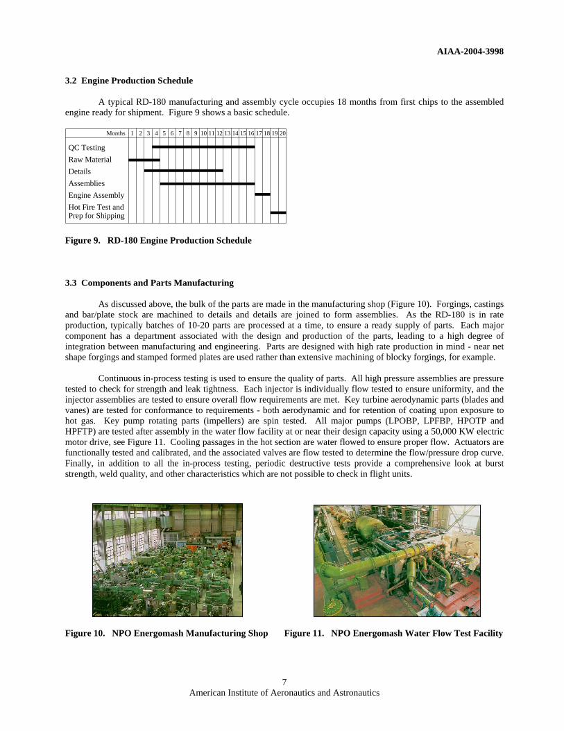
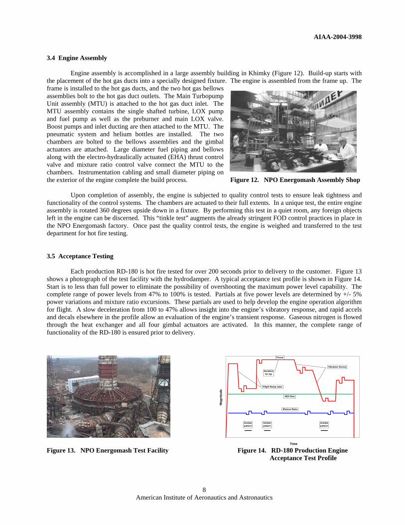
As discussed above, the bulk of the parts are made in the manufacturing shop (Figure 10). Forgings, castings and bar/plate stock are machined to details and details are joined to form assemblies. As the RD-180 is in rate production, typically batches of 10-20 parts are processed at a time, to ensure a ready supply of parts. Each major component has a department associated with the design and production of the parts, leading to a high degree of integration between manufacturing and engineering. Parts are designed with high rate production in mind - near net shape forgings and stamped formed plates are used rather than extensive machining of blocky forgings, for example.
Continuous in-process testing is used to ensure the quality of parts. All high pressure assemblies are pressure tested to check for strength and leak tightness. Each injector is individually flow tested to ensure uniformity, and the injector assemblies are tested to ensure overall flow requirements are met. Key turbine aerodynamic parts (blades and vanes) are tested for conformance to requirements - both aerodynamic and for retention of coating upon exposure to hot gas. Key pump rotating parts (impellers) are spin tested. All major pumps (LPOBP, LPFBP, HPOTP and HPFTP) are tested after assembly in the water flow facility at or near their design capacity using a 50,000 KW electric motor drive, see Figure 11. Cooling passages in the hot section are water flowed to ensure proper flow. Actuators are functionally tested and calibrated, and the associated valves are flow tested to determine the flow/pressure drop curve. Finally, in addition to all the in-process testing, periodic destructive tests provide a comprehensive look at burst strength, weld quality, and other characteristics which are not possible to check in flight units. Figure 10. NPO Energomash Manufacturing Shop Figure 11. NPO Energomash Water Flow Test Facility
QC TestingRaw MaterialDetailsAssembliesEngine AssemblyHot Fire Test andPrep for Shipping
1 2 3 4 5 6 7 8 9 10 11 12 13 14 15 16 17 18 19 20Months
AIAA-2004-3998
8 American Institute of Aeronautics and Astronautics
3.4 Engine Assembly
Engine assembly is accomplished in a large assembly building in Khimky (Figure 12). Build-up starts with the placement of the hot gas ducts into a specially designed fixture. The engine is assembled from the frame up. The frame is installed to the hot gas ducts, and the two hot gas bellows assemblies bolt to the hot gas duct outlets. The Main Turbopump Unit assembly (MTU) is attached to the hot gas duct inlet. The MTU assembly contains the single shafted turbine, LOX pump and fuel pump as well as the preburner and main LOX valve. Boost pumps and inlet ducting are then attached to the MTU. The pneumatic system and helium bottles are installed. The two chambers are bolted to the bellows assemblies and the gimbal actuators are attached. Large diameter fuel piping and bellows along with the electro-hydraulically actuated (EHA) thrust control valve and mixture ratio control valve connect the MTU to the chambers. Instrumentation cabling and small diameter piping on the exterior of the engine complete the build process. Figure 12. NPO Energomash Assembly Shop
Upon completion of assembly, the engine is subjected to quality control tests to ensure leak tightness and functionality of the control systems. The chambers are actuated to their full extents. In a unique test, the entire engine assembly is rotated 360 degrees upside down in a fixture. By performing this test in a quiet room, any foreign objects left in the engine can be discerned. This “tinkle test” augments the already stringent FOD control practices in place in the NPO Energomash factory. Once past the quality control tests, the engine is weighed and transferred to the test department for hot fire testing. 3.5 Acceptance Testing
Each production RD-180 is hot fire tested for over 200 seconds prior to delivery to the customer. Figure 13 shows a photograph of the test facility with the hydrodamper. A typical acceptance test profile is shown in Figure 14. Start is to less than full power to eliminate the possibility of overshooting the maximum power level capability. The complete range of power levels from 47% to 100% is tested. Partials at five power levels are determined by +/- 5% power variations and mixture ratio excursions. These partials are used to help develop the engine operation algorithm for flight. A slow deceleration from 100 to 47% allows insight into the engine’s vibratory response, and rapid accels and decals elsewhere in the profile allow an evaluation of the engine’s transient response. Gaseous nitrogen is flowed through the heat exchanger and all four gimbal actuators are activated. In this manner, the complete range of functionality of the RD-180 is ensured prior to delivery.
Figure 13. NPO Energomash Test Facility Figure 14. RD-180 Production Engine Acceptance Test Profile
0%
10%
20%
30%
40%
50%
60%
70%
80%
90%
100%
0 10 20 30 40 50 60 70 80 90 100 110 120 130 140 150 160 170 180 190 200 210
Time
Mag
nitu
de
Duration for Isp
Flight Ramp rates
HEX flow
Gimbalpattern
Gimbalpattern
Gimbalpattern
Mixture Ratio
Vibration Survey
Thrust

AIAA-2004-3998
9 American Institute of Aeronautics and Astronautics
Acceptance test data is recorded on over 100 individual sensors in and around the engine. Pressures, temperatures, vibration, valve position and many other parameters are monitored and compared to both engine limits and historical experience. A comprehensive data review is performed on all measured and derived parameters. Any out of limit or out of family data is reviewed and dispositioned.
All hardware is once again examined post-test. Internal borescope inspections, external visual inspections, leak tests and electrical system tests verify the hardware’s acceptability for flight. Finally, after all ground test instrumentation is removed, the engine is cleaned and packaged for shipment. 3.6 Engine Delivery
Engine delivery to the customer occurs after successful completion of the hot fire test and a review of the engine paperwork by representatives of RD AMROSS and the customer. An extensive two week review verifies and validates all engine hardware passports, configuration management data and test data. Ultimately, complete compliance to all Engine Specification and Interface Control Document requirements is assured.
Once engine buy-off has occurred, accepted engines are held at the Khimky facility prior to shipment. Typically 2-5 RD-180 engines are air-shipped using Antonov AN-124 aircraft directly from Moscow’s Sheremetevo Airport, Figure 15. RD-180 located less than 10 miles from the NPO Energomash facility, to Denver Engine Delivery at Denver International Airport in Colorado. Figure 15 shows a RD-180 engine in International Airport its shipping container being unloaded from the aircraft in Denver.
IV. Engine/Vehicle Integration Processing and Launch Support 4.1 Overview
After engine delivery, the RD-180 engine is integrated with either the Atlas III or Atlas V boosters. Integration activities occur at Lockheed Martin’s Final Assembly Building (FAB) in Littleton, CO. Upon completion of the engine integration work, the booster is flown via air cargo to the launch site where final launch processing tasks are performed. All current launches are from Cape Canaveral Air Force Station (CCAFS) for Atlas III/V, however, future Atlas V launches will also be conducted from Vandenberg Air Force Base (VAFB), starting at the end of 2005.
The RD-180 engine is designed to minimize the work required to integrate, test and launch. There are 11 plumbing interfaces to mate to the vehicle, and in addition there are 3 panels containing the engine electrical interfaces. In most cases, the minimum test requirements are only to verify that the plumbing connections are leak proof, and the electrical connections are intact in order to support functional testing of critical systems. The level of engine testing required at the launch site is also streamlined to facilitate tight launch schedules. Currently all integration and launch tasks are monitored by joint NPO Energomash / Pratt & Whitney teams.
The subsequent sections will describe in more detail the tasks that are performed on the engine at each location, and also highlight some of the lessons learned since the successful conclusion of the first article campaigns. 4.2 Engine/Vehicle Integration After delivery to Lockheed Martin, the engine goes through a detailed receiving inspection. Figure 16 shows an engine in Lockheed Martin’s facilities after opening of the shipping container, ready for the receiving inspection. This is primarily a visual inspection but also includes a review of the engine logbook, which contains documents covering critical manufacturing pedigree, acceptance test results, engine configuration, and remaining component life.

AIAA-2004-3998
10 American Institute of Aeronautics and Astronautics
Prior to mating the engine with the booster tanks, an uninstalled electrical test is performed. This automated test is performed by an Electrical Test Unit (ETU), which performs approximately 3000 individual readings on the engine to establish baseline electrical health and readiness for engine installation activities, see Figure 17. Performing this test with the automated ETU equipment has reduced the test time from 5 shifts for the manual test procedure to a one-shift automated operation. Figure 16. Engine in Receiving Inspection Figure 17. Electrical Testing on the RD-180 using
the ETU (foreground) After the engine is installed, the following engine plumbing interfaces are mated to the vehicle:
a. LOX feedline b. RP-1 feedline c. Chilldown exit d. Helium bottle charge e. High flow ambient nitrogen f. Heated nitrogen purge g. Hydraulic supply h. Hydraulic return i. Heat exchanger inlet j. Heat exchanger outlet k. Abort purge helium (Atlas V only)
After all plumbing interfaces are mated, engine leak checks are performed. Engine leak checks consist of
pressure decay, helium detector, and flow-meter checks to verify the integrity of the engine (LOX, RP-1, pneumatic, and hot gas duct systems) and the engine interfaces. Leak tests on the RD-180 are performed using a Pneumatic Test Unit (PTU).
The vehicle electrical harnesses are then mated to the engine, see Figure 18. A series of installed electrical
tests are performed by the ETU on critical circuits to ensure the integrity of the mated connectors. This includes continuity readings and pressure switch tests.
Figure 18. The RD-180 Electrical Interface Mated to the Vehicle

AIAA-2004-3998
11 American Institute of Aeronautics and Astronautics
At this point, the hydraulic connections from the vehicle to the Remote Hydraulic Cart (RHC) are made and
bled. The engine chambers are then hydraulically repositioned from a shipping configuration to a null configuration to allow the vehicle heat shield to be installed. The RHC can be seen in Figure 17, and is driven by a remote pump in a Hydraulic Test Unit (not shown). All actuator command functions to the engine to accomplish these hydraulic tasks are provided by the ETU. The final automated hydraulic tests are performed on the engine. This consists of functional tests of the engine thrust control and mixture ratio valves, as well as functional and clearance tests of the Thrust Vector Control (TVC) actuators and chambers. Engine tests are now complete, and the booster is ready to be shipped to the launch site. Five Atlas III and three Atlas V boosters have been successfully integrated in the FAB to date. One Atlas III and two Atlas V boosters are currently in work. Lessons learned from integrating this first series of boosters include altering the sequence of tasks to allow some engine tests to be performed in parallel, and relaxing test limits to accommodate environmental fluctuations. In the future, work will continue to feed lessons learned back into the integration flow to further optimize integration schedules. At present, without any interruptions from external events or problems, the engine portion of booster integration lasts approximately 3-4 weeks, which has been reduced from 10 weeks experienced during the first article campaigns. The goal is to reduce this time frame even further. 4.3 Engine Check-out on the Launch Vehicle After arrival of the booster stage at the launch site, the booster is erected at the launch pad, and a comprehensive engine visual inspection is performed in the vertical orientation. Figure 19 shows an Atlas V booster upon arrival inside the Atlas Spaceflight Operations Center (ASOC) at Cape Canaveral. Figure 20 shows an Atlas III booster at Cape Canaveral being prepared for erection at the launch pad. Figure 19. Atlas V Booster at upon arrival Figure 20. Atlas III Booster at Cape Canaveral inside the ASOC at Cape Canaveral just prior to Erection at the Launch Pad (Courtesy of Lockheed Martin Corporation) (Courtesy of Lockheed Martin Corporation)
The engine pre-launch tests are part of integrated vehicle tests that are summarized as follows:
a. Engine solenoid simulator installation (prevents accidental solenoid activation) b. Initial power on testing (general engine control and instrumentation health) c. Ampoule simulator installation d. Engine internal and interface leak checks (repeat of FAB leak check) e. Hydraulic functional tests f. Simulated flight (engine start and abort command sequence verification)

AIAA-2004-3998
12 American Institute of Aeronautics and Astronautics
g. Wet dress rehearsal (WDR) h. Live hypergol ampoule installation i. Final engine and ampoule leak checks j. Engine solenoid simulator removal and final control path checkout k. Final visual inspection
These tests are monitored by a joint NPO Energomash / Pratt & Whitney operations team. Facilities have
been set up at the launch sites to accommodate independent ITAR-compliant mission support rooms. In these rooms, engine data, video, and communications are independently monitored and evaluated by the two teams. Figure 21 shows NPO Energomash and associated Lockheed Martin RD-180 support personnel in a mission support room at the Atlas Spaceflight Operations Center (ASOC) located at CCAFS. This room is used to monitor critical engine tests and events, including WDR and launch countdown. Pratt & Whitney RD-180 operations personnel are in a similar room.
Figure 21. NPO Energomash in ASOC Mission Support Room Pre-launch data from all testing is evaluated and feeds into a more comprehensive engine launch readiness review held at Pratt & Whitney’s facility approximately one week prior to launch. At approximately two days before launch, all engine tests are complete, and a summarized launch readiness review is presented to Lockheed Martin at the launch site. Currently, five Atlas III and three Atlas V boosters have been processed at CCAFS, and have been successfully used on Atlas launches. The lessons learned from these activities include altering test sequences to allow some engine tasks to be performed in parallel, the elimination of redundant tests, and the optimization of engine limits to reflect worst case vehicle and external environments. Atlas V vehicle processing times continue to be reduced as experienced is gained. From an initial duration of over 6 months during first article campaigns, Atlas III and V processing times have been as low as approximately 1.5 months, with actual RD-180 engine testing being less than 25% of that. The lessons learned process is expected to further reduce launch site engine processing times to assist Lockheed Martin in achieving even more optimized launch processing cycles. To date, during all the time spent integrating the engine to various boosters and performing pre-launch testing, the RD-180 engine hardware, checkout procedures, or support teams have never delayed shipment to a launch site, have never suspended or delayed a WDR or launch countdown, and have never been the cause of a launch slip. 4.4 Engine Flight Summary
To date, there have been 8 flights from CCAFS with Atlas boosters powered by RD-180 engines. All flights met or exceeded contractual requirements for targeted orbits. Table 2 provides a complete listing of all eight RD-180 powered Atlas launches to date.

AIAA-2004-3998
13 American Institute of Aeronautics and Astronautics
Table 2. RD-180 Flight History
RD-180 Engine Serial Number
Vehicle Tail Number
Vehicle Series
Spacecraft Customer
Launch Date
2T AC-201 Atlas IIIA EUTELSAT 05/24/00
4T AC-204 Atlas IIIB EchoStar VII 02/21/02
9T AV-001 Atlas V 401 EUTELSAT 08/21/02
5T AC-205 Atlas IIIB AsiaSat 4 04/11/03
10T AV-002 Atlas V 401 Hellas-Sat 05/13/03
11T AV-003 Atlas V 521 Rainbow 1 07/17/03
3T AC-203 Atlas IIIB Navy UHF F-11 12/17/03
7T AC-202 Atlas IIIA MBSAT 03/13/04
Comprehensive reviews of flight data have not revealed any engine issues that would require changes to the engine hardware configuration. Engine performance has met or exceeded specification requirements on each flight to date. This also means that no significant changes are currently required to engine acceptance test, vehicle integration, or pre-launch checkout approaches. All lessons learned from the flight data are currently in a category consisting of ways to optimize in-flight vehicle software control of the RD-180 engine.
V. Summary and Conclusions
The RD-180 engine is a high performance, cost-effective booster engine with several unique features, which enable Atlas launch vehicle growth, enhanced launch vehicle effectiveness and mission payload flexibility. The engine is a 900,000 lbf thrust, high specific impulse staged combustion cycle LOX/kerosene engine, which has been in production since 1998 for use on Atlas III and Atlas V launch vehicles. Production engines are being provided to Lockheed Martin by RD AMROSS, a 50/50 Pratt & Whitney / NPO Energomash Joint Venture company incorporated in the US. Current production engines are being built and acceptance tested by NPO Energomash in Russia, and are delivered to Lockheed Martin in Denver for vehicle integration. Engine acceptance processing, engine integration and launch support activities are conducted by joint NPO Energomash / Pratt & Whitney teams.
To date, 23 engines have been delivered and 8 have been flown on missions from Cape Canaveral, with 100% mission success. Lessons learned during post-production engine integration and launch support processing are being incorporated to streamline those activities and make them more efficient and cost-effective in the future. A Vandenberg launch site pathfinder program will make that site operational for Atlas V launches in the future, with a first launch expected at the end of 2005. The RD-180 engine will also be used in the GX program, with an Initial Launch Capability at the Japanese Tanegashima launch site in 2006.
AIAA-2004-3998
14 American Institute of Aeronautics and Astronautics
VI. References
1 Popp, M., Parsley, R.C., “International Cooperation in Space Launch Propulsion”, AIAA-2003-2906, International Air and Space Symposium, Dayton, OH, July 2003.
2 Sasso, S.E., Karas, J.C., “Atlas III & Atlas V - 21st Century Launch Systems”, IAF-00-V.6.02, 51st International Astronautical Congress, Rio de Janeiro, Brazil, October 2000.
3 Sowers, G., “First Flight - Atlas V Evolved Expendable Launch Vehicle”, AIAA-2002-4204, 38th Joint
Propulsion Conference, Indianapolis, IN, July 2002. 4 Winn, R., “Atlas V - First to Flight”, AIAA-2003-8277, 21st AIAA International Communications Satellite
System Conference, Yokohama, Japan, April 2003. 5 Gillespie, T., “Atlas V Heavy Launch System”, AIAA-2004-4062, 40th Joint Propulsion Conference, Fort
Lauderdale, FL, July 2004. 6 Bliss, R., Lollini, D., Miyoshi, K., “Overview of The Galaxy Express Launch Vehicle Program”, AIAA-2003-
2262, 39th Joint Propulsion Conference, Huntsville, AL, July 2003. 7 Katorgin, B.I., Chvanov, V.K., Chelkis, F.Y., Ford, R.N., Tanner, L.G., “Atlas with RD-180 Now”, AIAA-
2001-3961, 37th Joint Propulsion Conference, Salt Lake City, UT, July 2001. 8 Tanner, L.G., “Development and Characteristics of the Russian / American RD-180 Rocket Engine”, AIAA
Liquid Propulsion Short Course, 38th Joint Propulsion Conference, Indianapolis, IN, July 2002.