
Basic Knowledge of Antenna and Antenna SelectionBasic Knowledge of Antenna and Antenna Selection

RC2500 Satellite Antenna Controller V1.34
Contents Subject to Change
24 January 2012
Research Concepts, Inc.
9501 Dice Lane
Lenexa, KS 66215 USA
913.422.0210
www.researchconcepts.com


WARRANTY
One Year Limited Warranty
Research Concepts, Inc., RCI, warrants to the original purchaser this product shall be free from defects in material and workmanship for one year, unless expressed otherwise, from the date of the original purchase.
During the warranty period, RCI will provide, free of charge, both parts and labor necessary to correct such defects.
To obtain such warranty service, the original purchaser must:
1. Notify RCI as soon as possible after discovery of a possible defect of:
a. the model and serial number
b. identity of the seller and date of purchase
c. detailed description of the problem, including details on the electrical connection to associated equipment’s and list of such equipment, and circumstances when problem arose.
d. Obtain a return material authorization (RMA) number from RCI.
2. Deliver the product to RCI, or ship the same in its original container or equivalent, fully insured and shipping charges prepaid.
Correct maintenance, repair and use are important to obtain proper performance from this product. Therefore, read the instruction manual carefully and completely. This warranty does not apply to any defect that RCI determines is due to:
1. Improper maintenance or repair, including the installation of parts or accessories that do not conform to the quality and specifications of the original parts.
2. Misuse, abuse, neglect, or improper installation including disregard for installation of backup or safety override equipment.
3. Accidental or intentional damage.
4. Lightening or acts of God.
There are no implied warranties.
The foregoing constitutes RCI’s entire obligation with respect to this product, and the original purchaser and any user or owner shall have no other remedy and no claim for incidental or consequential damages. Some states do not allow limitations or exclusions of incidental or consequential damages, so the above limitation and exclusion may not apply to you.
This warranty gives you specific legal rights and you may also have other rights, which may vary from state to state.
For service information:
Phone: (913) 422-0210
FAX: (913) 422-0211
EMAIL: [email protected]


RC2500 Manual Revision History
7 July, 1998 v1.00a
Original Manual derived from RC2000C Az/El Manual v1.10
16 July, 1998 v1.00b
added inclination estimator, PCB layouts
12 April, 1999 v1.10a
made various corrections, added hardware documentation, and appendices discussing: pol-pot sensing, RC2500 and the SA 8841, RC2500 and the Satcom 4020, and the firmware revision history.
21 July 2000 v1.20a
further corrections and clarifications, added appendices for: 36VDC driven antennas, Electrospace 93f2, Harris 7022, NPL 9000, Andrew LMKDS.
19 October 2001 v1.20b
added Appendix R, the RC2500 ACU Working with SSE Antenna Interface Unit. Also added, Appendix S Andrew Plug Compatible Controller.
29 April 2010 v1.21
Added Polarization Display Scale Factor to section 5.8.5
04 May 2010 v1.33
Added new sections:
3.4.8 Jammed Sensing Configuration 5.4.6 Continuous Step Tracking 5.4.7 Periodic Peaking on Geostationary Satellites 07 June 2010 v1.34 Updated software version. 24 January 2012 v.134
Updated Appendix S with a description and table for Connector J1. Replaced sections 3.3.1, 3.3.1.1, 3.3.1.2, 3.3.1.3, 3.3.3

TABLE OF CONTENTS
CHAPTER 1 – INTRODUCTION 1 1.1 Organization of this Manual 1 1.2 Before You Begin 1
CHAPTER 2 – BASIC FUNCTION DESCRIPTION 2 2.1 Front Panel 2 2.2 Changing Modes with the MODE Key 4 2.3 Mode Descriptions 4 2.4 Mode Access 7 2.5 Expert Access 7
CHAPTER 3 – INSTALLATION/ SETUP 8 3.1 Controller Versions 8 3.2 Before You Begin 8 3.3 Mechanical and Electrical Installation 9
Resolver Input 11 3.3.1 Azimuth, Elevation, and Polarization Resolvers 11
3.3.1.1 Resolver Resolution and Accuracy 11 3.3.1.2 Physical Mounting of Resolvers 11 3.3.1.3 Resolver Electrical Connections 13
Auxiliary Input Connection, J4 15 Note: Pin 8 (LIM SRC) is not normally used. This is the isolated supply that powers the limit sensing circuitry. An External Positive voltage of 5 to 12 Volts may be connected here, however R13 must be removed from the PC Board first. The Negative terminal of this supply is Pin (LIM COM). 15 Motor Control Connector, J5 16 *NOTE: Azimuth directions are given for the Northern Hemisphere, reverse these for use in the Southern Hemisphere. 16 3.3.2 Antenna Interface Connections 17
3.3.2.1 7134 Summary and Individual Limits Versions Connections 18 3.3.2.2 9135 Version Connections 20
3.3.3 AGC Interface Connection 22 3.3.4 PC Remote Control Interface Connection 23
3.4 Software Configuration 24 3.4.1 Polarization Equipment Code 24 3.4.2 Reversing the Resolver Sense Direction. 24 3.4.3 Fast and Slow Speed Setting 25 3.4.4 Determine Offset Angles 25 3.4.5 Programming Satellites 26 3.4.6 Setting AZ/EL/POL Drive Parameters 26 3.4.7 Simultaneous Azimuth and Elevation Movement 27 3.4.8 Jammed Sensing Configuration 28
3.5 Installation and Setup Checklist 29 CHAPTER 4 – INCLINED ORBIT SATELLITES 30
4.1 Geostationary and Inclined Orbit Satellites 30 4.2 RC2500B Tracking Algorithm 32
4.2.1 STEP_TRACK 33 4.2.2 PROGRAM_TRACK 34 4.2.3 Intelli-Search 34
4.3 Implementing the Tracking Algorithms 36 4.3.1 Location Information 36 4.3.2 Antenna Radiation Pattern 36 4.3.3 Real Time Clock 37 4.3.4 Receiver AGC Signal 37
4.4 Configuring the Tracking System 37 4.4.1 AGC Adjustment and Configuration 37
4.4.1.1 Single Receiver - Single Frequency Band Inclined Orbit Satellite AGC Setup 38 4.4.1.2 Single Receiver - Dual Frequency Band Inclined Orbit Satellite AGC Setup 40 4.4.1.3 Using Two AGC Channels 41 4.4.1.4 Amplifier Gain vs. Frequency Characteristics 41
4.4.2 CONFIG Mode Data 42 4.4.3 Initiating a Track on an Inclined Orbit Satellite 43 4.4.6 Tracking Problems 44
4.5 Inclined Orbit Satellite Setup Checklist 45 CHAPTER 5 – MODES IN-DEPTH FUNCTION DESCRIPTION 46
5.1 MANUAL Mode 46
5.2 AUTO Mode 46 5.3 REMOTE Mode 47 5.4 TRACK Mode 47
5.4.1 SEARCH Sub-mode 47 5.4.2 STEP TRACK Sub-mode 48 5.4.3 PROGRAM TRACK Sub-mode 49 5.4.4 TRACK Mode - ERROR Sub-mode 49 5.4.5 TRACK MENU 49 5.4.6 Continuous Step Tracking 51 5.4.7 Periodic Peaking on Geostationary Satellites 52
5.5 SETUP Mode 52 5.6 RESET Mode 54 5.7 DELETE Mode 55 5.8 CONFIG Mode 55
5.8.1 Reverse Sensor Direction 56 5.8.2 Simultaneous Azimuth and Elevation Movement 56 5.8.3 Remote Communication Parameters 56 5.8.4 Position Display Offsets 57 5.8.5 Polarization Display Scale Factor 57 5.8.6 Polarization Equipment Code 58 5.8.7 Azimuth, Elevation, and Polarization Drive Options 58 5.8.8 Time and Date Settings 60 5.8.9 Signal Strength Parameters 60 5.8.10 Antenna Parameters 61 5.8.11 Track Mode Parameters 62
5.8.11.1 MAX TRACK ERROR 62 5.8.11.2 SEARCH ENABLE 63 5.8.11.3 SEARCH WIDTH 63
5.8.12 Expert Access Flag 63 5.8.13 Reset System Data 64
CHAPTER 6 – SPECIFICATIONS 65 CHAPTER 7 – TROUBLESHOOTING/ALARM CODES 66
7.1 SYSTEM ERROR CODES 66 LOW BATTERY 66 ESTOP 66 MAINTENANCE 66 SUMMARY LIMIT 66 UP, DOWN, CW, CCW limits 67 ANT AZIM, ANT ELEV, ANT POL 67 AZIM SLOW SPEED, ELEV SLOW SPEED 67 COMM PORT 67 POL OPTIONS 67 AZ/EL OPTIONS 67 TIME/DATE 67 ANT/RCVR CONFIG 67 TRACK CONFIG 68
7.2 TRACK MODE ERRORS 68 JAMMED 68 LIMIT 68 RUNAWAY 68 DRIVE 68 PEAK LIMIT 68 SYSTEM 68 CHECKSUM 68
7.3 OPERATIONAL TROUBLESHOOTING TIPS 68 ANTENNA MUST BE PEAKED MANUALLY AFTER AN AUTO-MOVE 68 ANT AZIM, ANT ELEV or ANT POL ERRORS OCCUR 69 ENTRY SELECTED HOLDS INVALID DATA 69 GAPS IN THE TRACK TABLE 69
APPENDIX A – EXPERT ACCESS / RESET SYSTEM DATA CODE 71 APPENDIX B – FIELD UPGRADING 72
Updating RC2500 Antenna Controllers that are In-Service. 72 To Perform a Complete RC2500 System Reset 73 To Convert the RC2500 from 115VAC to 230VAC Operation: 73 RC2500 Non-Volatile Memory Items Worksheet 1 74
CONFIG MODE ITEMS 74 Satellite positions stored in memory 74
RC2500 Non-Volatile Memory Items Worksheet 2 75
CONFIG MODE ITEMS 75 Satellite positions stored in memory 75
APPENDIX C – RS-422 SERIAL INTERFACE 76 RS-232 to RS-422 Protocol Converter 76 Software 76
APPENDIX D – THE RCI RS422 INTERFACE SPECIFICATION 78 Introduction 78 Electrical Specifications 78 Physical Specifications 78 Data Format 80 Message Protocol 80 Message Format 80
Message Delimiters 80 Address Character 81 Command Character 81 Check Character 81 Message Timing 81
Command Restrictions 81 Slave State Diagram: Introduction 81 Mnemonics Description 82 States Description 82
APPENDIX E – RC2500 COMMUNICATIONS PROTOCOL 84 Revision History 84 Overview 84 Communications Parameters 84
APPENDIX F – ESTIMATING SATELLITE INCLINATION 95 APPENDIX G – SCHEMATICS/ PCB LAYOUTS 99 APPENDIX H – POLARIZATION SENSING WITH A POTENTIOMETER 109
General Description 109 An Example 113
APPENDIX I – REPLACING THE SA 8840 CONTROLLER 114 APPENDIX J – REPLACING THE RSI/ SATCOM 4010 CONTROLLER 118 APPENDIX K – DRIVING 36VDC MOTORS 119
Single Speed 36 VDC AIU for an Antenna with TVRO-type Actuators 119 1.0 Scope 119 2.0 Smart Booster 119 2.1 Smart Booster Modifications 120 2.2 Smart Booster I/O 120 2.3 Smart Booster Documentation 121 3.0 RC2500 Interface to the AIU 121 3.1 Wiring Diagrams 123
APPENDIX L – REPLACING THE ELECTROSPACE 93C-23 CONTROLLER 132 APPENDIX M – REPLACING THE HARRIS 7022 136 APPENDIX N – REPLACING THE NPL 9000 139
Setting Soft Limits for RC2500 Controllers which Replace the NPL 9000 142 Introduction 142 Setting the Soft Limits 142 Corrupted Limits Alarm Messages 142 Soft Limits Theory of Operation 142 Resetting the Limits 143
APPENDIX O – REPLACING THE ANDREW APC 100/ APC 300 145 LMKDS Input 145
Antenna I/O Connector 146 Auxiliary I/O Connection 147
Setting Soft Limits for RC2500 Controllers which Replace Andrew Products 148 Introduction 148 Setting the Soft Limits 148 Corrupted Limits Alarm Messages 148 Soft Limits Theory of Operation 148 Resetting the Limits 149
APPENDIX P – USING THE RC2500 151

APPENDIX Q – WORKING WITH THE SA 8151 152 APPENDIX R – WORKING WITH THE SSE ANTENNA INTERFACE UNIT 155 APPENDIX S – ANDREW PLUG COMPATIBLE CONTROLLER 157
Hardware Description and Interconnects 157 AGC Input Connector, J1 158 AGC Interface Connection 158 Resolver Input Connector, J2 159 Auxiliary Input Connection, J4 160 Motor Control Connector, J5 161
Software Features 162 Setting Soft Limits for RC2500 Controllers which Replace Andrew Products 162 Introduction 162 Setting the Soft Limits 162 Corrupted Limits Alarm Messages 162 Soft Limits Theory of Operation 162 Resetting the Limits 163
APPENDIX T – VERSION 1.15 ADDENDUM 176 5.8.1 Sensor Type and Reverse Direction 177 5.8.11 Expert Access Flag 178
SOFTWARE REVISION HISTORY 180 Software Version Number Suffix Legend 180


RC2500 Antenna Controller Chapter 1 Introduction 1
Research Concepts, Inc. • 9501 Dice Lane • Lenexa, Kansas • 66215 • USA www.researchconcepts.com
Chapter 1 – INTRODUCTION The RC2500 is a satellite antenna controller manufactured by Research Concepts Inc. (RCI). The RC2500 operates with low-voltage resolvers for position feedback and an Antenna Interface Unit or A.I.U. which is typically mounted at the antenna pad. The RC2500 features the popular user interface found in the RC2000 series of Antenna Controllers manufactured by RCI and can store up to 30 satellites in its non-volatile memory. It is PC remote controllable through the standard RS-422 port. Simple remote control software is supplied with the unit. The SABUS-based remote control protocol is compatible with many head-end and broadcast automation systems.
The RC2500A model is designed to operate with geostationary satellites. A single Az/El position is stored in memory for each satellite. The RC2500B supports all the features of the ‘A’ model but also tracks up to 5 of the 30 stored inclined orbit satellites through the use of step track and memory track algorithms. Automatic polarization tracking is not supported.
A version of the RC2500 (A or B) is available which is plug compatible with the Vertex 7134 antenna controller. The EPROM for this version of the software is labeled ‘summary’. Another version of the controller is available which supports individual azimuth ccw, azimuth cw, elevation down, elevation up, polarization ccw, and polarization cw limit switches. The EPROM for this version of the controller is labeled ‘individual’. For the ‘individual limits’ version of the controller the antenna position sensor and antenna stimulus interfaces are plug compatible with the Vertex 7134 controller. A third version is plug compatible with the Harris 9135 controller.
1.1 Organization of this Manual This manual is divided into two broad parts, Installation and Reference. The Installation part of this manual is designed to familiarize the user with the controller and guide him or her through the installation and configuration of the controller. The Reference portion of the manual gives a detailed description of all of the features and capabilities of the controller.
The Installation portion of the manual is comprised of Chapters 2 through 4. Chapter 2 explains the user interface and the basic operation of the unit. Chapter 3 guides the user through the physical installation and wiring of the unit as well as the initial software configuration. Chapter 4 covers all aspects of tracking inclined orbit satellites from setup to normal operations. Inclined orbit tracking is available only on the RC2500B model.
The Reference portion of this manual is comprised of chapters 5, 6, and 7 as well as the appendices which follow. These chapters of the manual describe the fields on the screens that the user will encounter, as well as the data that can be entered at any prompt. After the initial installation, when the user has become familiar with the operation of the controller, these chapters will probably be the only ones consulted by the user to handle the routine chores of adding new satellites and deleting old ones.
1.2 Before You Begin Please read and understand the manual. Time invested in understanding the installation and operation of the controller will insure satisfactory results. The unit has been tested thoroughly and will work accurately and reliably if it is installed and configured properly.
2 RC2500 Antenna Controller Chapter 2 Basic Function Description
Research Concepts, Inc. • 9501 Dice Lane • Lenexa, Kansas • 66215 • USA www.researchconcepts.com
Chapter 2 – BASIC FUNCTION DESCRIPTION This chapter describes the controller's front panel layout, user interface and basic operation. When the user has completed this chapter, he or she should have a basic understanding of the various operating modes of the unit, and be able to use the keyboard and liquid crystal display (LCD) to navigate through those modes.
2.1 Front Panel
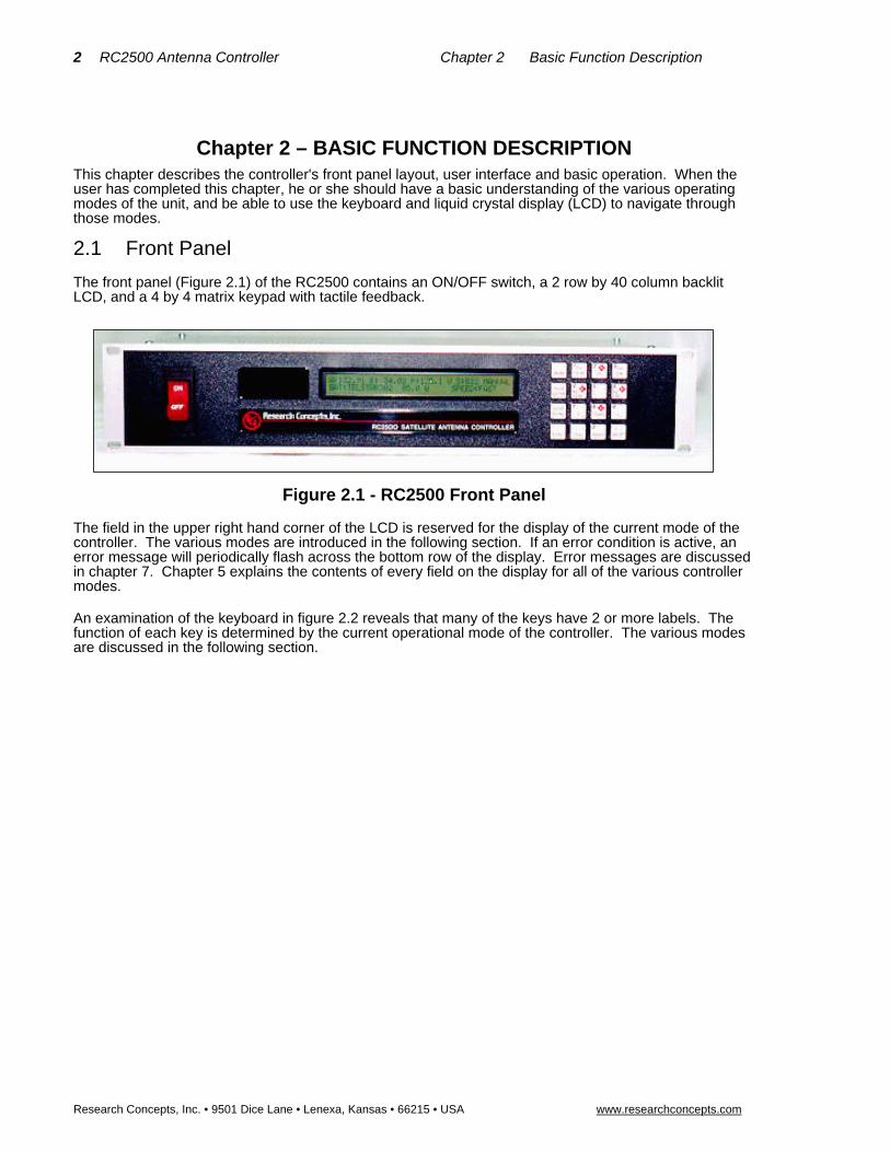
The front panel (Figure 2.1) of the RC2500 contains an ON/OFF switch, a 2 row by 40 column backlit LCD, and a 4 by 4 matrix keypad with tactile feedback.
Figure 2.1 - RC2500 Front Panel
The field in the upper right hand corner of the LCD is reserved for the display of the current mode of the controller. The various modes are introduced in the following section. If an error condition is active, an error message will periodically flash across the bottom row of the display. Error messages are discussed in chapter 7. Chapter 5 explains the contents of every field on the display for all of the various controller modes.
An examination of the keyboard in figure 2.2 reveals that many of the keys have 2 or more labels. The function of each key is determined by the current operational mode of the controller. The various modes are discussed in the following section.

RC2500 Antenna Controller Chapter 2 Basic Function Description 3
Research Concepts, Inc. • 9501 Dice Lane • Lenexa, Kansas • 66215 • USA www.researchconcepts.com
Figure 2.2 - RC2500 Keypad
MODE
This key allows the user to change the controller’s current mode. Modes are used to access the various functions of the controller. For example, when MANUAL mode is active the user can manually jog the antenna; When SETUP is active the user can program satellite position data into the controller’s non-volatile memory. The modes are divided into two groups: Operational Modes (which include MANUAL, AUTO, REMOTE, and TRACK modes) and Programming Modes (which include SETUP, DELETE, RESET, and CONFIG modes). To change from one GROUP to the other DEPRESS THE MODE KEY FOR AT LEAST FIVE SECONDS AND THEN RELEASE IT. To toggle between the modes in a given group rapidly depress and release the mode key.
SCROLL UP, SCROLL DOWN
These keys are used to scroll up or down through a list of items.
YES, NO
These keys are used to supply an answer to a yes or no type question.
ENTER
This key is used to select an entry from a list, terminate a prompt for some action by the user, or to complete the entry of numeric data.
0-9, DECIMAL POINT (with the stop key), BKSP
These keys are used for numeric entry. The BKSP key causes the cursor to move one column to the left writing over the character that was there.
SPEED
This key toggles the az/el speed from fast to slow and vice versa.
AZ CW, AZ CCW, UP, DOWN
These keys are used to manually jog the antenna in certain modes. CW refers to clockwise and CCW refers to counter clockwise. The sense of azimuth rotation is as seen by an observer located above the antenna. On early versions of the controller the AZ CW, AZ CCW, UP, and DOWN labels were not present on these keys. On these controllers (when certain modes are active) the left arrow key initiates ccw azimuth movement, the right arrow key initiates cw azimuth movement, the up arrow key initiates up elevation movement, and the down arrow key initiates down elevation movement.
Mode CCW
N
CW
Scroll
Scroll
Dn/No
Up/Yes
Enter
E W
VH
Stop
S
Speed
+/-
BKSP
1 2 3
4 5 6
7 8 9
0.
Up
Down
PolPol
AZCCW
AZCW

4 RC2500 Antenna Controller Chapter 2 Basic Function Description
Research Concepts, Inc. • 9501 Dice Lane • Lenexa, Kansas • 66215 • USA www.researchconcepts.com
E, W, N, S
These direction keys, E east, W west, N north, and S south specify a direction when entering latitude or longitude data.
POL CCW, POL CW, H, V
These keys control the antenna polarization. The CCW and CW keys skew the polarization control device counterclockwise and clockwise. The H and V keys are used to either select or specify the polarization position associated with a given satellite. Note that via CONFIG mode the user can specify the type of polarization control present in the system: none, single port, or dual port (simultaneous H and V).
STOP
During automatic moves this key may be used to halt the movement of the antenna.
Note that all of these keys are not active simultaneously. The function of each key is dependent on the current mode of the controller. In some modes certain keys are ignored.
2.2 Changing Modes with the MODE Key
The controller’s current mode is always displayed in the upper right hand corner of the controller’s display. The user can switch the current controller mode by use of the MODE key. The MODE key is always active - when the MODE key is depressed and released, the controller's current mode will change.
The modes are divided into two groups, referred to as mode groups. The Operational mode group consists of the MANUAL, AUTO, REMOTE, and TRACK modes. TRACK Mode is only available on the RC2500B model. The Programming mode group consists of the SETUP, RESET, DELETE, and CONFIG. The Programming modes are typically only used during system installation and configuration. The Operational modes are used in everyday operation of the controller.
To switch between modes in a group, rapidly depress and release the MODE key. To switch to a mode in the other group of modes, depress the MODE key for at least five seconds and release. Note that the Expert Access feature can prevent access to certain modes. See section 2.5 for more information on the Expert Access feature.
2.3 Mode Descriptions
The mode system on the RC2500 antenna controller resembles the menu system used with many personal computer (PC) programs. On a PC program a menu system allows the user to perform operations or to enter in data. The user must navigate through the menu structure to the particular menu which allows access to the function or data that the user wishes to manipulate. On the RC2500 the mode which is currently active is always displayed in the upper right hand corner of the LCD.
On power-up, either MANUAL or TRACK mode will be active. If the RC2500B unit powered down while tracking an inclined orbit satellite TRACK mode will receive control, otherwise MANUAL mode will be active on power up. The RC2500A always powers up in MANUAL Mode.
Here is a summary of the modes implemented on the RC2500 ...
MANUAL
A: 120.77 E: 71.25 P: 174.7 S:635 MANUAL SAT: SBS 2 97.0 W SPEED:FAST
In manual mode you can:
5. Jog the antenna in elevation and azimuth using the AZIM CW, AZIM CCW, ELEV UP, and ELEV DOWN keys.
6. Toggle the speed from fast to slow (and vice versa) with the SPEED key.
7. Toggle the signal strength display using the SCROLL UP and SCROLL DOWN keys to show the voltage at AGC Channel 1 (displays 1:###), the voltage at AGC Channel 2 (displays 2:###) or the stronger of AGC1 or AGC2 (displays S:###).

RC2500 Antenna Controller Chapter 2 Basic Function Description 5
Research Concepts, Inc. • 9501 Dice Lane • Lenexa, Kansas • 66215 • USA www.researchconcepts.com
Currently the AGC Channel Scroll feature is not supported
When MANUAL mode is active, the following information is displayed on the top row of the LCD: azimuth position (A:), elevation position (E:), polarization position if applicable (P:), and the current signal strength (S:, 1:, or 2:).
If the controller is configured for a polarization control device (enabled via CONFIG mode), the polarization position (P:) will be displayed and the user will be able to jog the antenna in polarization with the POL CCW and POL CW keys. If the controller is configured for a single port polarization control device, the H and V keys can be used to select either the horizontal or vertical polarization of the satellite on which the satellite was last automatically positioned.
The signal strength is derived from a receiver automatic gain control (AGC) output.
The bottom row of the LCD displays the name and longitude of the satellite that was the last target of an AUTO move, and either the FAST or SLOW banner to indicate the speed which will be used for jogging the antenna. When the antenna is being jogged at slow speed the voltage applied to the actuator is displayed to the right of the SLOW speed banner.
AUTO
SELECT A SATELLITE: PANAMSAT-1 AUTO USE SCROLL UP/DOWN, ENTER TO SELECT
This mode allows the user to automatically position the antenna on any satellite that has been programmed into memory. The list of programmed satellites is reviewed via the SCROLL UP/DOWN keys, and the ENTER key initiates the automatic move. The STOP key will terminate the move. When the antenna is positioned, the controller will switch to MANUAL mode for a geostationary satellite, and track mode is activated for an inclined orbit satellite.
REMOTE
A: 120.77 E: 71.25 P: 174.7 S: 635 REMOTE SAT:SBS 2 FAST
In this mode the controller receives and acts on commands received via the communications port. This mode can only receive control if enabled via a CONFIG mode item. The only key which is active is the MODE key, which can be used to switch to a different mode.
SETUP
A:120.77 E: 71.25 P:174.7 S: 635 MANUAL SAT: SBS 2 SELECT:BRAZLST A1 FAST
This mode allows a user to associate a satellite name with an antenna azimuth and elevation position and to assign horizontal and vertical polarization positions to that satellite. The satellite name and the antenna position data associated with it is stored in non-volatile memory. Once stored in memory, the satellite is available for recall by AUTO mode.
When SETUP mode is first activated, the user can jog the antenna using the AZIM CCW, AZIM CW, ELEV DOWN, ELEV UP, and ELEV DOWN keys. On controllers configured for polarization control the polarization may be skewed using the POL CCW and POL CW keys. The user peaks the antenna on the desired satellite. The satellite name is selected using the SCROLL UP and SCROLL DOWN keys (the selected satellite name is displayed to the right of the SELECT: banner). If the desired satellite name is not available select the USER entry to manually enter a satellite name.
When the ENTER key is depressed the user is prompted to enter:
1. The satellite longitude,
2. Whether or not the satellite is in an inclined orbit (and if so, the satellite frequency band and the current inclination of the satellite's orbital plane to the earth's equatorial plane - more on this in the chapter on tracking), and
3. The horizontal and vertical polarization values for the satellite (if the controller has been configured to support polarization control).

6 RC2500 Antenna Controller Chapter 2 Basic Function Description
Research Concepts, Inc. • 9501 Dice Lane • Lenexa, Kansas • 66215 • USA www.researchconcepts.com
When the user has entered all of the requested data, the controller will respond with "DATA ACCEPTED", and the user can jog the antenna to another satellite and repeat the procedure. If the satellite just entered was an inclined orbit satellite, the controller will activate TRACK mode and will initiate a track on the satellite.
RESET
AZ: DRIVE EL: OK PL:SENSOR RESET RESET AXIS: 1-AZ/EL, 3-POL
This mode allows the user to examine the error status of the motor drive circuits and reset them if a fault has occurred. The drive systems of each axis are independent. A DRIVE error indicates that the drive circuits detected an over current fault and shut down. A JAMMED error indicates that the antenna actuators were commanded to move but no movement was detected. A RUNAWAY error indicates that antenna movement was detected when the actuators were not energized. A SENSOR error indicates backwards movement of a sensor. The ‘proper’ sense of antenna movement is described in Chapter 3.
When a RUNAWAY error is sensed for the azimuth axis, the elevation error status will indicate OFFAXIS. Similarly, if an elevation RUNAWAY error is sensed the azimuth axis error status will indicate OFFAXIS. When a RUNAWAY error is sensed the controller disables the drives via the A.I.U.’s DRIVE_ENABLE output. When this output is activated both the azimuth and elevation axes are disabled. OFFAXIS indicates that the axis is disabled because of an error that occurred on another axis.
An error condition for a given axis may be reset by depressing the numeric key associated with that axis as described on the bottom row of the display. Errors are described in chapter 7.
DELETE
SELECT A SATELLITE: PANAMSAT-1 DELETE USE SCROLL UP/DOWN, ENTER TO SELECT
This mode allows the user to delete satellites from non-volatile memory. The SCROLL UP/DOWN and ENTER keys are active.
CONFIG
ANTENNA LATITUDE LL.L:45.0 CONFIG TENTHS AFTER DEC. PT ENT,BKSP,SCRLL ^v
This mode allows the user to view and enter configuration data into the controller. This data is stored in non-volatile memory and is used to set certain parameters and enable or disable certain controller options. The following parameters and options are controlled or configured via data entered into the controller from CONFIG mode:
communication port parameters
simultaneous azimuth/elevation movement
azimuth, elevation, and polarization sensor offsets
time and date
az/el angle display parameters
az/el slow speed and movement control parameters
polarization options
az/el drive systems options
antenna parameters
tracking system setup and control parameters
expert access
reset all system data to default values
In CONFIG mode, the SCROLL UP/DOWN keys are used to select the parameter to be viewed or modified. If asterisks are displayed in the parameter field, it means that the present value is invalid. It can be modified using the numeric keypad to key in a new value, followed by ENTER. (For the
RC2500 Antenna Controller Chapter 2 Basic Function Description 7
Research Concepts, Inc. • 9501 Dice Lane • Lenexa, Kansas • 66215 • USA www.researchconcepts.com
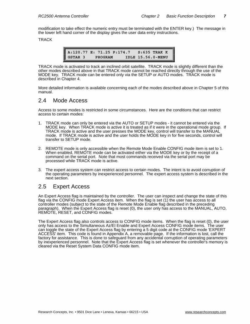
modification to take effect the numeric entry must be terminated with the ENTER key.) The message in the lower left hand corner of the display gives the user data entry instructions.
TRACK
A:120.77 E: 71.25 P:174.7 S:635 TRAK K GSTAR 3 PROGRAM IDLE 15.56.0-MENU
TRACK mode is activated to track an inclined orbit satellite. TRACK mode is slightly different than the other modes described above in that TRACK mode cannot be reached directly through the use of the MODE key. TRACK mode can be entered only via the SETUP or AUTO modes. TRACK mode is described in Chapter 4.
More detailed information is available concerning each of the modes described above in Chapter 5 of this manual.
2.4 Mode Access
Access to some modes is restricted in some circumstances. Here are the conditions that can restrict access to certain modes:
1. TRACK mode can only be entered via the AUTO or SETUP modes - it cannot be entered via the MODE key. When TRACK mode is active it is treated as if it were in the operational mode group. If TRACK mode is active and the user presses the MODE key, control will transfer to the MANUAL mode. If TRACK mode is active and the user holds the MODE key in for five seconds, control will transfer to SETUP mode.
2. REMOTE mode is only accessible when the Remote Mode Enable CONFIG mode item is set to 1. When enabled, REMOTE mode can be activated either via the MODE key or by the receipt of a command on the serial port. Note that most commands received via the serial port may be processed while TRACK mode is active.
3. The expert access system can restrict access to certain modes. The intent is to avoid corruption of the operating parameters by inexperienced personnel. The expert access system is described in the next section.
2.5 Expert Access
An Expert Access flag is maintained by the controller. The user can inspect and change the state of this flag via the CONFIG mode Expert Access item. When the flag is set (1) the user has access to all controller modes (subject to the state of the Remote Mode Enable flag described in the preceding paragraph). When the Expert Access flag is reset (0), the user only has access to the MANUAL, AUTO, REMOTE, RESET, and CONFIG modes.
The Expert Access flag also controls access to CONFIG mode items. When the flag is reset (0), the user only has access to the Simultaneous Az/El Enable and Expert Access CONFIG mode items. The user can toggle the state of the Expert Access flag by entering a 5 digit code at the CONFIG mode 'EXPERT ACCESS' item. This code is found in Appendix A, a removable page. If the information is lost, call the factory for assistance. This is done to safeguard from any accidental corruption of operating parameters by inexperienced personnel. Note that the Expert Access flag is set whenever the controller's memory is cleared via the Reset System Data CONFIG mode item.

8 RC2500 Antenna Controller Chapter 3 Installation/Setup
Research Concepts, Inc. • 9501 Dice Lane • Lenexa, Kansas • 66215 • USA www.researchconcepts.com
Chapter 3 – INSTALLATION/ SETUP This chapter guides the user through the installation and the initial software setup. The procedures outlined in this chapter cover the mechanical and electrical installation of the unit, setting the azimuth and elevation limits, determining the azimuth and elevation slow speed parameters, and programming the satellite positions into non-volatile memory. Italicized items refer to CONFIG mode items the installer may or may not have to modify.
3.1 Controller Versions There are several different drive-output and operating firmware versions of the RC2500 product that allow it to operate with antenna interface units of various manufacturers. All RC2500 versions use the same processor board. Currently, these hardware/firmware versions are as follows:
7134 Summary Limits Version
This version is pin compatible with the Vertex 7134 antenna -controller. It features a summary limit input (all six limits are wired in series) and dual speed operation. This version can also be used with individual limits by utilizing pins of the Aux I/O connector and different firmware.
9135 Version
Meant as a retrofit to existing Harris antennas using the 9135 controller, this version features individual limits and a variable slow speed controlled by a pulse-width–modulated signal from the RC2500. This version uses a unique drive board.
Other Hardware Versions
There have been several other variations of the RC2500 with the hardware based on one of the two versions above. Refer to the final appendices (H and greater) for details of these variants.
There exists an RC2500A and RC2500B version for each of these antenna types. The RC2500B is capable of tracking inclined-orbit satellites and the RC2500A is not.
3.2 Before You Begin Before installing the unit the installer must ensure that the line voltage is correct, the controller's memory has been cleared, and that he or she is familiar enough with the mode system described in Chapter 2 to place the controller in any desired mode. All units are shipped from the factory with memory cleared, a line cord appropriate for the line voltage selected.
If the line cord received with the unit is not appropriate for the power available at the installation site, the installer should check the controller to ensure that the proper line voltage has been selected.
The RC2500 can be configured to operate on either 115 VAC or 230 VAC. The AC input voltage the unit is currently configured for is displayed in a window located in the fuse holder. To change the AC input voltage selection, remove the fuse holder and reverse the jumper assembly (on which the ‘115’ and ‘230’ labels are located). The fuse holder is designed to accommodate 1/4” by 1 1/4” fuses. If the RC2500 is configured for 115 VAC operation, use a 2 amp slow blow type fuse. If the RC2500 is configured for 230 VAC operation, use a 1 amp slow blow type fuse.
When the AC line voltage has been verified, and before any of the antenna wiring has been connected, the installer should become familiar with the controller's user interface. It is not necessary to understand every aspect of the controller's operation to install the unit, but the installer should be familiar with the mode structure of the RC2500 and be able to use the MODE key to place the controller in any of the modes described in Chapter 2.
When the unit is powered up, it should be verified that the controller goes to MANUAL mode ('MANUAL' displayed in the upper right hand corner of the LCD). Before the controller is shipped from the factory, the memory is cleared. If the unit does not power up in Manual mode or if the memory is corrupted, the installer should perform a system reset to place the controller into a known state before proceeding with the installation.
To perform a system reset:

RC2500 Antenna Controller Chapter 3 Installation/Setup 9
Research Concepts, Inc. • 9501 Dice Lane • Lenexa, Kansas • 66215 • USA www.researchconcepts.com
1. Use the MODE key to place the controller into CONFIG mode ('CONFIG' displayed in the upper right hand corner of the LCD).
2. Use the SCROLL DOWN and SCROLL UP keys to bring up the RESET SYSTEM DATA screen. If the RESET SYSTEM DATA item does not appear, the EXPERT ACCESS flag (see section 2.5) may need to be reset.
3. To inspect the status of the EXPERT ACCESS flag use the SCROLL DOWN key (while still in CONFIG mode) to bring up the EXPERT ACCESS CONFIG mode item. If a 1 does not appear in the data entry field, enter the 5 digit code described in section 2.5 to toggle the EXPERT ACCESS flag on. This will allow access to the RESET SYSTEM DATA CONFIG mode item.
4. At the RESET SYSTEM DATA screen enter the same 5 digit code followed by the ENTER key.
3.3 Mechanical and Electrical Installation This section covers the mechanical and electrical installation of the unit. For rack mount models, use 4 #10-32 mounting screws to secure the unit to a standard 19" rack. It is assumed that an Antenna Interface Unit (A.I.U.) has been installed and is operational at the antenna. This “outdoor unit” is connected to the RC2500 by at least one 25-conductor cable. For a minimum-level of operations of the antenna through the RC2500, resolver connections for the active axes as well as the antenna interface connections must be made.
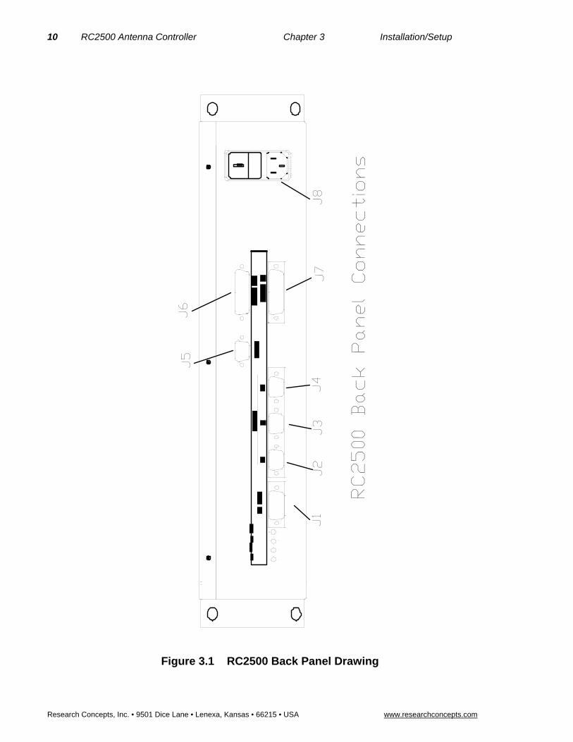
All connections to the RC2500 are made at the back panel. The RC2500 back panel contains 4 holes for potentiometer screw adjustment and 8 connectors of various types. The purpose of each of these connectors is listed below. Please refer to figure 3.1 for a diagram of the controller back panel during the following discussion.
Connector J1 is a DB-15 receptacle used primarily for AGC signal input while the RC2500 is tracking inclined orbit satellites. In addition to this function, J1 supports 4 bits of digital I/O and various bus voltages which allow for future expansion.
J2, J3, and J4 are identical DB-9 receptacles used to bring the low voltage resolver signals into the RC2500. These act as the primary antenna-position sensing inputs. The duplicate pinout of these connectors allow for easy testing of the position sensing circuitry by swapping connectors.
J5 is another DB-9 receptacle used for the remote control interface of the RC2500. The port conforms to the RS-422 electrical specification. Mis-connections of J5 with J2, J3, or J4 will not cause system damage.
J7, located to the right of J4, is a DB-25 plug that acts as the Antenna I/O connector. This connector acts as the antenna motion control port of the RC2500. The port consists of multiple solid-state low-side relay drivers rated at 700mA sink each. Max voltage is +27VDC on these drivers. In addition to the drivers this port supports several 24 VDC, low current, status inputs with isolated return paths. For the 7134 summary limit version and the 9135 version, this connector acts as the only AIU connection. For the 7134 version with individual limits, all antenna motion commands use this connector along with a single limit input, the remaining limit inputs are routed through J7.
J6, located directly above J7, is the Auxiliary I/O connector. This port, based on a DB-25 receptacle, supports axis-specific limit inputs as well as contact closures for summary faults and peripheral equipment control. A +5 VDC regulated output (200mA max), a +24 VDC unregulated output (1 Amp max), and an analog voltage input are also available.
The final connector, J8, is an IEC power inlet combination. This module serves as a voltage switch (115VAC/230VAC), single-ended fuse holder (2 Amp slow-blow at 115VAC; 1 AMP slow-blow at 230VAC), as well as supporting the standard inlet for Line, Neutral, and Ground from the AC mains
10 RC2500 Antenna Controller Chapter 3 Installation/Setup
Research Concepts, Inc. • 9501 Dice Lane • Lenexa, Kansas • 66215 • USA www.researchconcepts.com
Figure 3.1 RC2500 Back Panel Drawing
J1
J2
J3
J4
J5
J6
J7
J8
RC2500 Back Panel Connections

RC2500 Antenna Controller Chapter 3 Installation/Setup 11
Research Concepts, Inc. • 9501 Dice Lane • Lenexa, Kansas • 66215 • USA www.researchconcepts.com
Resolver Input
3.3.1 Azimuth, Elevation, and Polarization Resolvers
The low-voltage resolvers used for position sensing with the RC2500 are meant to directly sense the angle of each of the principal antenna axes. Resolvers act as rotary transformers that have a primary coil driven by a sinusoidal AC voltage and 2 secondaries, one oriented to produce a voltage proportional to the Cosine of the angular position and the second oriented to produce a voltage proportional to the Sine of the angular position. A converter inside the RC2500 calculates the position from these two voltages.
Andrew antennas use two different resolver types, single-speed and two-speed. A single speed resolvers produce 360 degrees of electrical travel for 360 degrees of shaft travel. A two-speed resolver produces 720 degrees of electrical travel for 360 degrees of shaft travel. Multi-speed resolvers are used by industry to improve the fundamental pointing resolution and accuracy of the system.
3.3.1.1 Resolver Resolution and Accuracy
The 360° angular region (or 180° region in the case of two-speed resolvers) measured by the resolvers and on-board resolver-to-digital converters is divided into 216 (or 65,536) discrete positions. Therefore one ‘count’ is equivalent to 360 / 65,536 = 0.005493° (or 0.0027466° for two-speed). This number represents the resolution of the angular mesurement system of the RC2500. The RC2500 can position an antenna to no better than within 0.005493° of the target position. The actual positioning performance will depend strongly on the mechanical and electrical drive components of the system. The accuracy of the system depends almost solely upon the accuracy of the resolvers used. The standard resolvers shipped with the RC2500 have + 7 arc-minute accuracy or + 0.11667°. Two speed resolvers tend to have accuracies that approach twice that of a single speed resolver.
3.3.1.2 Physical Mounting of Resolvers
The recommended resolvers, RCI P/N Z-RESOLVER are size 11, that is they are 1 inch in diameter and 1and ¾ inches long. They are shipped with 12 inch flying lead connections that extend from the side of the resolver body opposite the shaft end. A drawing of the resolver is shown in Figure 3.2. Special bracketry may be required to mount the resolvers to the principle axes of the antenna. This will most certainly be the case if this is a retrofit installation and larger 120VAC synchros were originally used. A bellows type strain relief is recommended for the interconnection of the resolver shaft to the principal axis shaft.
Care should be taken to ensure that the resolvers are protected from the weather. In most instances, a rubber “boot” is constructed which covers most of the resolver body and has a single liquid tight fitting for the resolver cable. The resolver cable is meant to run directly to the RC2500.
The resolvers shaft must be positioned such that the sensed position does not wrap around (from 0.00 to 360.00 or 360.00 to 0.00) within the antenna’s normal range of movement for a given installation.

12 RC2500 Antenna Controller Chapter 3 Installation/Setup
Research Concepts, Inc. • 9501 Dice Lane • Lenexa, Kansas • 66215 • USA www.researchconcepts.com
Figure 3.2 Resolver Mechanical Drawing

RC2500 Antenna Controller Chapter 3 Installation/Setup 13
Research Concepts, Inc. • 9501 Dice Lane • Lenexa, Kansas • 66215 • USA www.researchconcepts.com
3.3.1.3 Resolver Electrical Connections
NOTE: SHIELDED CABLE IS REQUIRED FOR THE RESOLVER CONNECTIONS. THE SHIELD MUST BE CONNECTED TO RC2500 CHASSIS GROUND AT THE CONTROLLER AND MUST NOT BE CONNECTED AT THE ANTENNA.
Three shielded twisted-pairs for each resolver are required to minimize noise pickup and cross-coupling, which can result in antenna positioning errors. A cable such as Belden 87777 (RCI p/n CBL-3x2x22_STP) is recommended. Most resolvers have flying lead connections. Wire-to-wire interconnects can be accomplished with solder and heat shrink tubing or a water-proof crimp connector such as RCI p/n CN-JIZR.
J2, J3, and J4 are identical DB-9 receptacles The duplicated pinout of these connectors allow for easy testing of the position sensing circuitry by swapping connectors. The individual pin definitions are as follows:
Pin # Description Resolver Wire Lead Color
1 Ref. Drain Wire No Connect at Resolver
2 Resolver Reference Red w/ White Stripe
3 Resolver SIN - Blue
4 Resolver COS - Black
5 Resolver SIN + Yellow
6 COS Drain Wire No Connect at Resolver
7 SIN Drain Wire No Connect at Resolver
8 Resolver Reference Yellow w/ White Stripe
9 Resolver COS + Red
The resolver type position sensors wired as in the table above should result in the sensed position changing in the correct manner when the antenna is moved. The A.I.U. should already have been wired such that the axes are all moving in the correct direction with local jog controls if any.
Here is the ‘correct’ relationship between antenna movement and sensed position.
4. Azimuth CW antenna movement (as viewed by an observer located above the antenna) must result in an increasing sensed position.
5. Elevation UP antenna movement must result in an increasing sensed position.
6. When the controller’s POL CW key is depressed, the sensed polarization position must increase.
The LCD display of the RC2500 may show limit indications rather than the digitized angles. Proper display of the sensed angles will not be possible until all of the antenna position limit connections are accounted for.

14 RC2500 Antenna Controller Chapter 3 Installation/Setup
Research Concepts, Inc. • 9501 Dice Lane • Lenexa, Kansas • 66215 • USA www.researchconcepts.com
J2, located on the left side of the back panel is the Resolver Input connector. This port, based on a DB-50P connector, supports three resolver inputs. The table below indicates the pin # and their usage.
J2 Pin #
& (resource #)
Description APC100/300 Pin #
1 AZ SIN HI 1 AZ SIN HI
2-4 not used 2-4 not used
5 GROUND FOR DRAIN WIRE 5 not used
6-7 not used 6-7 not used
8 EL COS - 8 EL COS RTN
9-11 not used 9-11 not used
12 POL SIN - 12 POL SIN RTN
13 POL COS + 13 POL COS HI
14-15 No Connection 14-15 not used
16 EL REF - 16 EL REF RTN
17 POL REF + 17 POL REF HI
18 No Connection 18 not used
19 AZ COS - 19 AZ COS RTN
20-22 No Connection 20-22 not used
23 EL SIN - 23 EL SIN RTN
24 EL COS + 24 EL COS HI
25-27 No Connection 25-27 not used
28 POL SIN + 28 POL SIN HI
29-30 No Connection 29-30 not used
31 AZ REF - 31 AZ REF RTN
32 EL REF + 32 EL REF HI
33 No Connection 33 not used
34 AZ SIN - 34 AZ SIN RTN
35 AZ COS + 35 AZ COS HI
36-38 No Connection 36-38 not used
39 EL SIN + 39 EL SIN HI
40-45 No Connection 40-45 not used
46 POL COS - 46 POL COS RTN
47 AZ REF + 47 AZ REF HI
48-49 No Connection 48-49 not used
50 POL REF - 50 POL REF RTN
RC2500 Antenna Controller Chapter 3 Installation/Setup 15
Research Concepts, Inc. • 9501 Dice Lane • Lenexa, Kansas • 66215 • USA www.researchconcepts.com
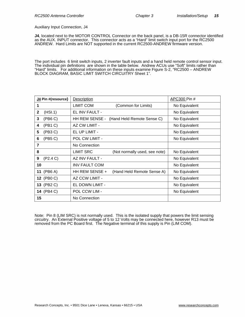
Auxiliary Input Connection, J4
J4, located next to the MOTOR CONTROL Connector on the back panel, is a DB-15R connector identified as the AUX. INPUT connector. This connector acts as a “Hard” limit switch input port for the RC2500 ANDREW. Hard Limits are NOT supported in the current RC2500-ANDREW firmware version.
The port includes 6 limit switch inputs, 2 inverter fault inputs and a hand held remote control sensor input. The individual pin definitions are shown in the table below. Andrew ACUs use “Soft” limits rather than “Hard” limits. For additional information on these inputs examine Figure S-2, “RC2500 – ANDREW BLOCK DIAGRAM, BASIC LIMIT SWITCH CIRCUITRY Sheet 1”.
J4 Pin #(resource) Description APC300 Pin #
1 LIMIT COM (Common for Limits) No Equivalent
2 (HSI.1) EL INV FAULT - No Equivalent
3 (PB6 C) HH REM SENSE - (Hand Held Remote Sense C) No Equivalent
4 (PB1 C) AZ CW LIMIT - No Equivalent
5 (PB3 C) EL UP LIMIT - No Equivalent
6 (PB5 C) POL CW LIMIT - No Equivalent
7 No Connection
8 LIMIT SRC (Not normally used, see note) No Equivalent
9 (P2.4 C) AZ INV FAULT - No Equivalent
10 INV FAULT COM No Equivalent
11 (PB6 A) HH REM SENSE + (Hand Held Remote Sense A) No Equivalent
12 (PB0 C) AZ CCW LIMIT - No Equivalent
13 (PB2 C) EL DOWN LIMIT - No Equivalent
14 (PB4 C) POL CCW LIM - No Equivalent
15 No Connection
Note: Pin 8 (LIM SRC) is not normally used. This is the isolated supply that powers the limit sensing circuitry. An External Positive voltage of 5 to 12 Volts may be connected here, however R13 must be removed from the PC Board first. The Negative terminal of this supply is Pin (LIM COM).

16 RC2500 Antenna Controller Chapter 3 Installation/Setup
Research Concepts, Inc. • 9501 Dice Lane • Lenexa, Kansas • 66215 • USA www.researchconcepts.com
Motor Control Connector, J5
J5, located on the right side of the back panel, is a DB-50R connector identified as the MOTOR CONTROL connector. This connector acts as the antenna motion control port of the RC2500-ANDREW ACU .
The port consists of 10 solid-state sinking drivers and a +12 Volt source for driving the optical isolator inputs of the Andrew outdoor unit. The individual pin definitions as well as their mating connection at the APC300 are shown in the table below. For additional information on this port examine Figure S-3, RC2500 – ANDREW BLOCK DIAGRAM, OUTPUT CIRCUITRY Sheet 2.
This information is meant to replace that contained in section 3.3.2 of the RC2500 Manual.
J5 Pin#(resource) Description APC300 Pin #
1 (PA1) Azimuth Drive East *, (0.4V = AZ move East) 1 AZ EAST -
2 (PA0) Azimuth Drive West *, (0.4V = AZ move West) 2 AZ WEST -
3 (PA2) Azimuth Drive Fast, (0.4V = AZ move Fast) 3 AZ FAST -
4 (PC1) Azimuth Drive Slow, (0.4V = AZ move Slow) 4 AZ SLOW -
5 (PA5) Elevation Drive Down, (0.4V = EL move Down) 5 EL DOWN -
6 (PA4) Elevation Drive Up, (0.4V = EL move Up) 6 EL UP -
7 (PA6) Elevation Drive Fast, (0.4V = EL move Fast) 7 EL FAST -
8 (PA7) Elevation Drive Slow, (0.4V = EL move Slow) 8 EL SLOW -
9 (PA3) Polarization Drive CCW, (0.4V = Pol move CCW) 9 POL CCW -
10 (PC2) Polarization Drive CW, (0.4V = Pol move CW) 10 POL CW -
11 – 17 No Connection No Connection
18 Drive +12 V 18 AZ EAST +
19 Drive +12 V 19 AZ WEST +
20 Drive +12 V 20 AZ FAST +
21 Drive +12 V 21 AZ SLOW +
22 Drive +12 V 22 EL DOWN +
23 Drive +12 V 23 EL UP +
24 Drive +12 V 24 EL FAST +
25 Drive +12 V 25 EL SLOW +
26 Drive +12 V 26 POL CCW +
27 Drive +12 V 27 POL CW +
28 Drive +12 V No connection
29 Drive +12 V No connection
30-50 No Connection No Connection
*NOTE: Azimuth directions are given for the Northern Hemisphere, reverse these for use in the Southern Hemisphere
.

RC2500 Antenna Controller Chapter 3 Installation/Setup 17
Research Concepts, Inc. • 9501 Dice Lane • Lenexa, Kansas • 66215 • USA www.researchconcepts.com
3.3.2 Antenna Interface Connections
The RC2500 is designed to operate with an Antenna Interface Unit (A.I.U.) sometimes referred to as an “outdoor box”. The A.I.U. contains the drive modules or contactors that switch power to the motors of the antenna mount. It also supports wiring from antenna mounted limit switches which, when actuated, shut down the motor drive for that axis/direction combination. Often the A.I.U. will have local jog controls that allow service personnel to move the antenna at the pedestal. An emergency disconnect should always be provided at the antenna pad for operating safety. This function may also be integrated into the A.I.U.
The antenna interface connections are made through DB-25 connectors. The low impedance nature of these connections make them relatively immune to outside interference. To further increase the interface’s immunity and to reduce possible emissions, a 25 conductor cable with an overall shield should be used. A cable such as Belden 9948 or equivalent (RCI p/n CBL-25_22) is recommended.
The RC2500 communicates with the A.I.U. through the use of open-collector relay drivers. These low-side drivers are designed to operate with 24VDC relays that have one side tied to the +24V loop supply originating in the outdoor box. These relays should always have locally mounted back EMF or “buck” diodes across the coil. Figure 3.3 illustrates typical interconnects for the Azimuth CW move command line. The relay drivers of the RC2500 are optically isolated, have internal current limits and are protected from over-voltage by metal oxide varistors.
In the version of the RC2500 that operates with the Harris 9135 A.I.U., 2 100mA high-side drivers are used to transmit a PWM waveform that controls the speed of the azimuth and elevation motors.
The A.I.U. transmits status information back to the RC2500 through low impedance current loops. These current loops drive the LED portion of opto-isolators in the RC2500. 5 to 10mA is the normal loop current for these circuits. They will, however reliably operate at 1 mA. An open-circuit will indicate a limit has been reached for most cases. This, combined with the opto-isolated drivers described above, allows the A.I.U. and RC2500 to have 5000V of isolation.
Figure 3.3 Typical Antenna Interface Unit Limit Switch/ Relay-Drive Wiring
18 RC2500 Antenna Controller Chapter 3 Installation/Setup
Research Concepts, Inc. • 9501 Dice Lane • Lenexa, Kansas • 66215 • USA www.researchconcepts.com
The different RC2500 versions will have different pin definitions for connectors J7 and J6. In the case of the 7134 summary limit version and the 9135 version, only J7 is required to make connection to the A.I.U. For the case of the 7134 individual limits version, both J7 and J6 connections are required.
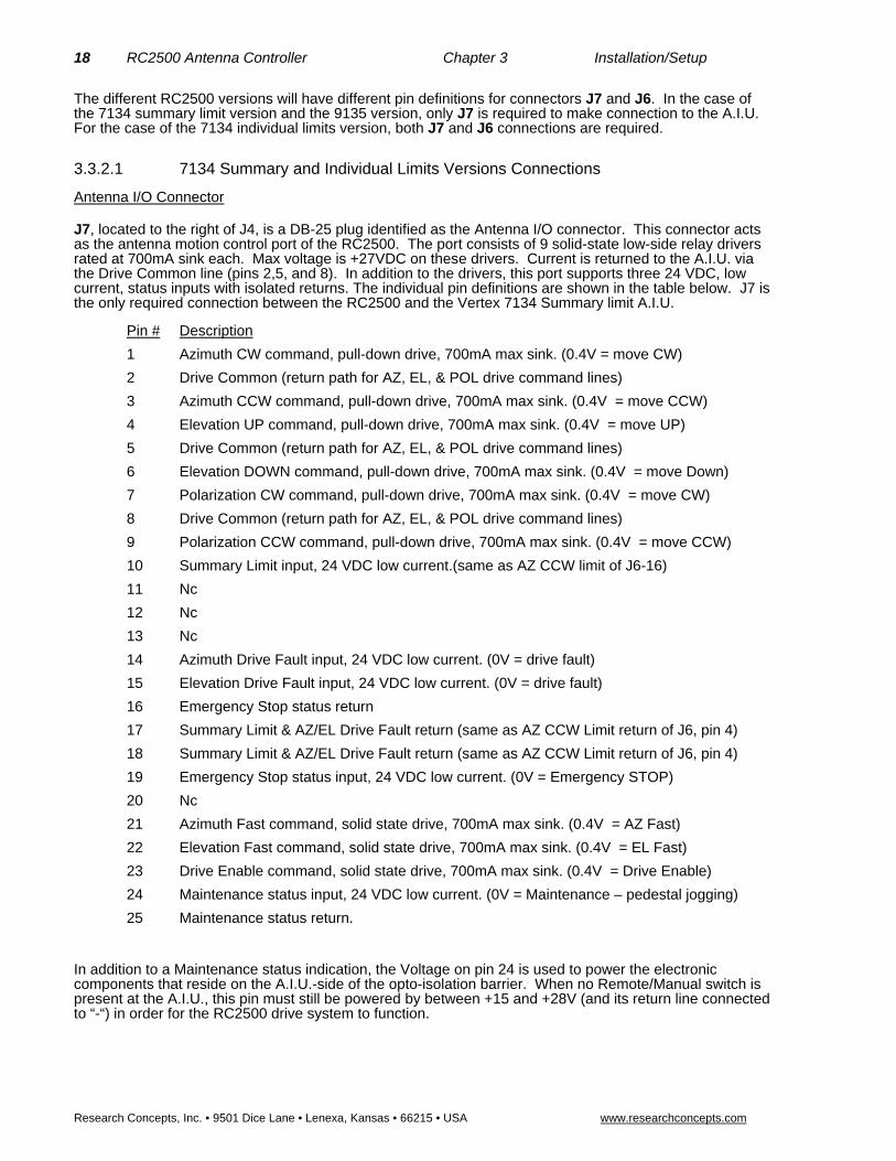
3.3.2.1 7134 Summary and Individual Limits Versions Connections
Antenna I/O Connector
J7, located to the right of J4, is a DB-25 plug identified as the Antenna I/O connector. This connector acts as the antenna motion control port of the RC2500. The port consists of 9 solid-state low-side relay drivers rated at 700mA sink each. Max voltage is +27VDC on these drivers. Current is returned to the A.I.U. via the Drive Common line (pins 2,5, and 8). In addition to the drivers, this port supports three 24 VDC, low current, status inputs with isolated returns. The individual pin definitions are shown in the table below. J7 is the only required connection between the RC2500 and the Vertex 7134 Summary limit A.I.U.
Pin # Description
1 Azimuth CW command, pull-down drive, 700mA max sink. (0.4V = move CW)
2 Drive Common (return path for AZ, EL, & POL drive command lines)
3 Azimuth CCW command, pull-down drive, 700mA max sink. (0.4V = move CCW)
4 Elevation UP command, pull-down drive, 700mA max sink. (0.4V = move UP)
5 Drive Common (return path for AZ, EL, & POL drive command lines)
6 Elevation DOWN command, pull-down drive, 700mA max sink. (0.4V = move Down)
7 Polarization CW command, pull-down drive, 700mA max sink. (0.4V = move CW)
8 Drive Common (return path for AZ, EL, & POL drive command lines)
9 Polarization CCW command, pull-down drive, 700mA max sink. (0.4V = move CCW)
10 Summary Limit input, 24 VDC low current.(same as AZ CCW limit of J6-16)
11 Nc
12 Nc
13 Nc
14 Azimuth Drive Fault input, 24 VDC low current. (0V = drive fault)
15 Elevation Drive Fault input, 24 VDC low current. (0V = drive fault)
16 Emergency Stop status return
17 Summary Limit & AZ/EL Drive Fault return (same as AZ CCW Limit return of J6, pin 4)
18 Summary Limit & AZ/EL Drive Fault return (same as AZ CCW Limit return of J6, pin 4)
19 Emergency Stop status input, 24 VDC low current. (0V = Emergency STOP)
20 Nc
21 Azimuth Fast command, solid state drive, 700mA max sink. (0.4V = AZ Fast)
22 Elevation Fast command, solid state drive, 700mA max sink. (0.4V = EL Fast)
23 Drive Enable command, solid state drive, 700mA max sink. (0.4V = Drive Enable)
24 Maintenance status input, 24 VDC low current. (0V = Maintenance – pedestal jogging)
25 Maintenance status return.
In addition to a Maintenance status indication, the Voltage on pin 24 is used to power the electronic components that reside on the A.I.U.-side of the opto-isolation barrier. When no Remote/Manual switch is present at the A.I.U., this pin must still be powered by between +15 and +28V (and its return line connected to “-“) in order for the RC2500 drive system to function.

RC2500 Antenna Controller Chapter 3 Installation/Setup 19
Research Concepts, Inc. • 9501 Dice Lane • Lenexa, Kansas • 66215 • USA www.researchconcepts.com
Auxiliary I/O Connection
J6, located directly above J7, is the Auxiliary I/O connector. This port, based on a DB-25 receptacle, supports isolated, axis-specific limit inputs as well as contact closures for summary faults and peripheral equipment control. A +5 VDC regulated output (200mA max), a +24 VDC unregulated output (1 Amp max), and an analog voltage input, all referenced to the RC2500 ground, are also available The individual pin definitions are shown in the table below. Both J6 and J7 are required when operating with a Vertex 7134 A.I.U. that support separate limits.
Pin # Description
1 Summary Fault dry contact COM, (3A @ 125VAC or 3A @ 30VDC).
2 Summary Fault dry contact NO, (3A @ 125VAC or 3A @ 30VDC).
3 Azimuth CW Limit return.
4 Azimuth CCW Limit return(same as Summary Limit-AZ/EL Drive Fault return,J7-17&-18)
5 Elevation Down Limit return.
6 Elevation Up Limit return
7 Polarization CW Limit return.
8 Polarization CCW Limit return.
9 Drive Common (return path, same as J7, pins 2,5,8)
10 PC0 output dry contact NC, (3A @ 125VAC or 3A @ 30VDC).
11 P0.2 Auxiliary analog/digital input 0 - +5 VDC.
12 Ground (for digital/analog I/O).
13 Ground for system bus voltages.
14 Summary Fault dry contact NC, (3A @ 125VAC or 3A @ 30VDC).
15 Azimuth CW Limit input, 24 VDC low current. (0V = CW Limit reached)
16 Azimuth CCW Limit input, 24VDC (0V = CCW Limit reached) (same as J7-10 ).
17 Elevation Down Limit input, 24 VDC low current. (0V = Down Limit reached)
18 Elevation UP Limit input, 24 VDC low current. (0V = Up Limit reached)
19 Polarization CW Limit input, 24 VDC low current. (0V = CW Limit reached)
20 Polarization CCW Limit input, 24 VDC low current. (0V = CCW Limit reached)
21 PC1 Relay Driver, 700mA max sink. (0.4V = Relay On)
22 PC0 output dry contact COM, (3A @ 125VAC or 3A @ 30VDC).
23 PC0 output dry contact NC, (3A @ 125VAC or 3A @ 30VDC).
24 +5 Volts DC digital power, 200mA max.
25 Unregulated +24 VDC bus voltage, 1 Amp max..
Once the above connections have been made, verify that antenna motion in the appropriate direction can be affected from the front panel in MANUAL mode.
20 RC2500 Antenna Controller Chapter 3 Installation/Setup
Research Concepts, Inc. • 9501 Dice Lane • Lenexa, Kansas • 66215 • USA www.researchconcepts.com
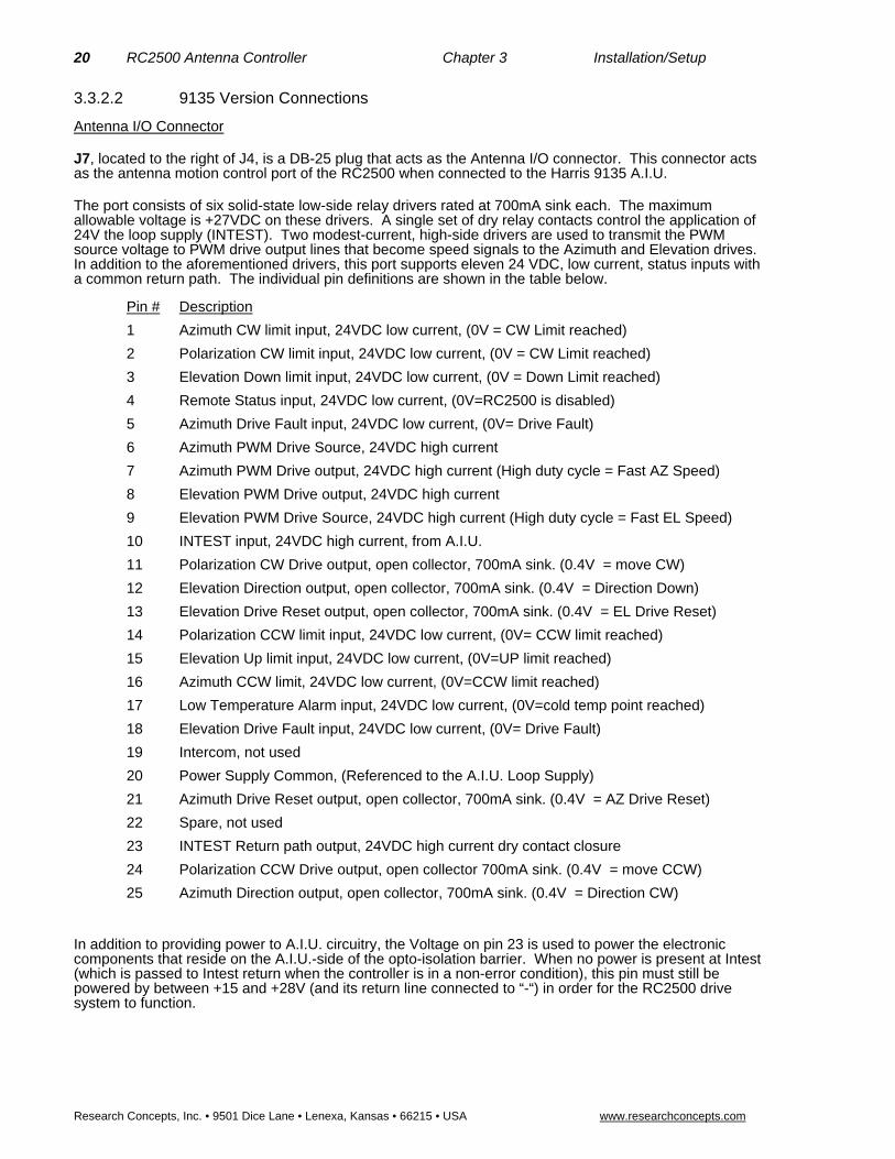
3.3.2.2 9135 Version Connections
Antenna I/O Connector
J7, located to the right of J4, is a DB-25 plug that acts as the Antenna I/O connector. This connector acts as the antenna motion control port of the RC2500 when connected to the Harris 9135 A.I.U.
The port consists of six solid-state low-side relay drivers rated at 700mA sink each. The maximum allowable voltage is +27VDC on these drivers. A single set of dry relay contacts control the application of 24V the loop supply (INTEST). Two modest-current, high-side drivers are used to transmit the PWM source voltage to PWM drive output lines that become speed signals to the Azimuth and Elevation drives. In addition to the aforementioned drivers, this port supports eleven 24 VDC, low current, status inputs with a common return path. The individual pin definitions are shown in the table below.
Pin # Description
1 Azimuth CW limit input, 24VDC low current, (0V = CW Limit reached)
2 Polarization CW limit input, 24VDC low current, (0V = CW Limit reached)
3 Elevation Down limit input, 24VDC low current, (0V = Down Limit reached)
4 Remote Status input, 24VDC low current, (0V=RC2500 is disabled)
5 Azimuth Drive Fault input, 24VDC low current, (0V= Drive Fault)
6 Azimuth PWM Drive Source, 24VDC high current
7 Azimuth PWM Drive output, 24VDC high current (High duty cycle = Fast AZ Speed)
8 Elevation PWM Drive output, 24VDC high current
9 Elevation PWM Drive Source, 24VDC high current (High duty cycle = Fast EL Speed)
10 INTEST input, 24VDC high current, from A.I.U.
11 Polarization CW Drive output, open collector, 700mA sink. (0.4V = move CW)
12 Elevation Direction output, open collector, 700mA sink. (0.4V = Direction Down)
13 Elevation Drive Reset output, open collector, 700mA sink. (0.4V = EL Drive Reset)
14 Polarization CCW limit input, 24VDC low current, (0V= CCW limit reached)
15 Elevation Up limit input, 24VDC low current, (0V=UP limit reached)
16 Azimuth CCW limit, 24VDC low current, (0V=CCW limit reached)
17 Low Temperature Alarm input, 24VDC low current, (0V=cold temp point reached)
18 Elevation Drive Fault input, 24VDC low current, (0V= Drive Fault)
19 Intercom, not used
20 Power Supply Common, (Referenced to the A.I.U. Loop Supply)
21 Azimuth Drive Reset output, open collector, 700mA sink. (0.4V = AZ Drive Reset)
22 Spare, not used
23 INTEST Return path output, 24VDC high current dry contact closure
24 Polarization CCW Drive output, open collector 700mA sink. (0.4V = move CCW)
25 Azimuth Direction output, open collector, 700mA sink. (0.4V = Direction CW)
In addition to providing power to A.I.U. circuitry, the Voltage on pin 23 is used to power the electronic components that reside on the A.I.U.-side of the opto-isolation barrier. When no power is present at Intest (which is passed to Intest return when the controller is in a non-error condition), this pin must still be powered by between +15 and +28V (and its return line connected to “-“) in order for the RC2500 drive system to function.

RC2500 Antenna Controller Chapter 3 Installation/Setup 21
Research Concepts, Inc. • 9501 Dice Lane • Lenexa, Kansas • 66215 • USA www.researchconcepts.com
Auxiliary I/O Connection
J6, located directly above J7, is the Auxiliary I/O connector. This port, based on a DB-25 receptacle, supports a single isolated input, contact closures for summary faults and peripheral equipment control as well as two open collector relay drivers similar to those found in J7. The INTEST, INTEST Return and Power Supply Common connections of J6 are duplicated here for convenience. A +24 VDC unregulated output (1 Amp max) referenced to the RC2500 ground is also available. The individual pin definitions are shown in the table below.
Pin # Description
1 Summary Fault dry contact COM, (3A @ 125VAC or 3A @ 30VDC).
2 Summary Fault dry contact NO, (3A @ 125VAC or 3A @ 30VDC).
3 PC0 dry contact COM, (3A @ 125VAC or 3A @ 30VDC).
4 PC0 dry contact NC, (3A @ 125VAC or 3A @ 30VDC).
5 PC0 dry contact NO, (3A @ 125VAC or 3A @ 30VDC).
6 Unregulated +24 VDC bus voltage, 1 Amp max.
7 Unregulated +24 VDC bus voltage, 1 Amp max.
8 Aux. Relay Drive 1, open collector relay driver, 700mA sink, (0.4V = Relay On)
9 Aux. Relay Drive 2, open collector relay driver, 700mA sink, (0.4V = Relay On)
10 INTEST (see J7 pin 10), 24VDC high current from A.I.U.
11 INTEST (see J7 pin 10), 24VDC high current from A.I.U.
12 INTEST Return (see J7 pin 23), 24VDC high current dry contact closure
13 INTEST Return (see J7 pin 23), 24VDC high current dry contact closure
14 Summary Fault dry contact NC, (3A @ 125VAC or 3A @ 30VDC).
15 Unregulated +24 VDC return, (RC2500 ground)
16 Unregulated +24 VDC return, (RC2500 ground)
17 Unregulated +24 VDC return, (RC2500 ground)
18 Unregulated +24 VDC return, (RC2500 ground)
19 Unregulated +24 VDC return, (RC2500 ground)
20 Unregulated +24 VDC return, (RC2500 ground)
21 Unregulated +24 VDC return, (RC2500 ground)
22 Auxiliary Input 1, 24VDC low current.
23 Auxiliary Input 1 Return, 24VDC low current.
24 Power Supply Common, (Referenced to the A.I.U. Loop Supply)
25 Power Supply Common, (Referenced to the A.I.U. Loop Supply)
Once the above connections have been made, verify that antenna motion in the appropriate direction can be affected from the front panel in MANUAL mode.

22 RC2500 Antenna Controller Chapter 3 Installation/Setup
Research Concepts, Inc. • 9501 Dice Lane • Lenexa, Kansas • 66215 • USA www.researchconcepts.com
3.3.3 AGC Interface Connection J1, located on the left side of the back panel is a DB-25P (plug). It supports the basic pin set for an Andrew AGC Connector and has several additional features. J1 is used primarily for AGC signal input while the RC2500B is tracking inclined orbit satellites. The RC2500A model does not support inclined orbit tracking modes. In addition to the AGC input function, J1 supports 4 bits of digital I/O and various bus voltages that allow for future expansion. In the APC100/300 AGC interface, there are two form C relay contacts. The RC2500 interface supports just one of these, PC3-relay which acts as a Summary Alarm.
The AGC voltage or received signal strength voltage from the system receiver must be between –15VDC and +15VDC. The signal may be either positive-going or negative-going for an increasing signal strength (selectable in the configuration menu). When the magnitude of the difference between the “on satellite” voltage and “off satellite” voltage is less than 1.3 volts AGC channel 1 should be used. For voltage differences greater than 1.3 volts use AGC channel 2. Four potentiometer adjustments at the back panel set the gain and offset for the two channels.
A shielded pair such as Alpha 1292C should be used to minimize external noise pickup on the AGC line. The shield should be connected at the RC2500 system ground and open circuited at the receiver or modem. For further discussion of the AGC inputs, AGC input tuning, and inclined-orbit tracking see Chapter 4.
The individual pin definitions of J1 ( for the APC100/300 interface and the RC2500 interface) are shown in the table below.
J1 Pin # RC2500ANDREW Signal Description APC300 Pin # & Description DB25P
1 HI CH1 INPUT AGC 1 Signal Input 1 Primary Beacon +
2 LO AGC Signal Return 2 Primary Return
3 HI CH2 INPUT AGC 2 Signal Input 3 Secondary Beacon +
4 LO AGC Signal Return 4 Secondary Return
5 not used not used
6 CH1 Select Output PC3-RY-NC 6 Selected Beacon
7 COM PC3-RY-COM 7 Tally Relay
8 CH2 Select Output PC3-RY-NO 8 Internal Connection
9 not used not used
10 not supported 10 FAULT/POWER OFF
11 not supported 11 COM SUMMARY ALARM
12 not supported 12 TALLY RELAY
13 not used not used
14 PC4 Digital I/O not used
15 PC5 Digital I/O not used
16 PC6 Digital I/O not used
17 PC7 Digital I/O not used
18 Digital Ground not used
19 +5 VOLT DC DIG POWER 500mA max. not used
20 Unreg. +24 VDC 500mA max. not used
21 Power Ground not used
22 -12 VOLTS DC 50mA max. not used
23 +12 VOLTS DC 50mA max not used
24 AGC 2 OFFSET TEST POINT not used
25 AGC 1 OFFSET TEST POINT not used
RC2500 Antenna Controller Chapter 3 Installation/Setup 23
Research Concepts, Inc. • 9501 Dice Lane • Lenexa, Kansas • 66215 • USA www.researchconcepts.com
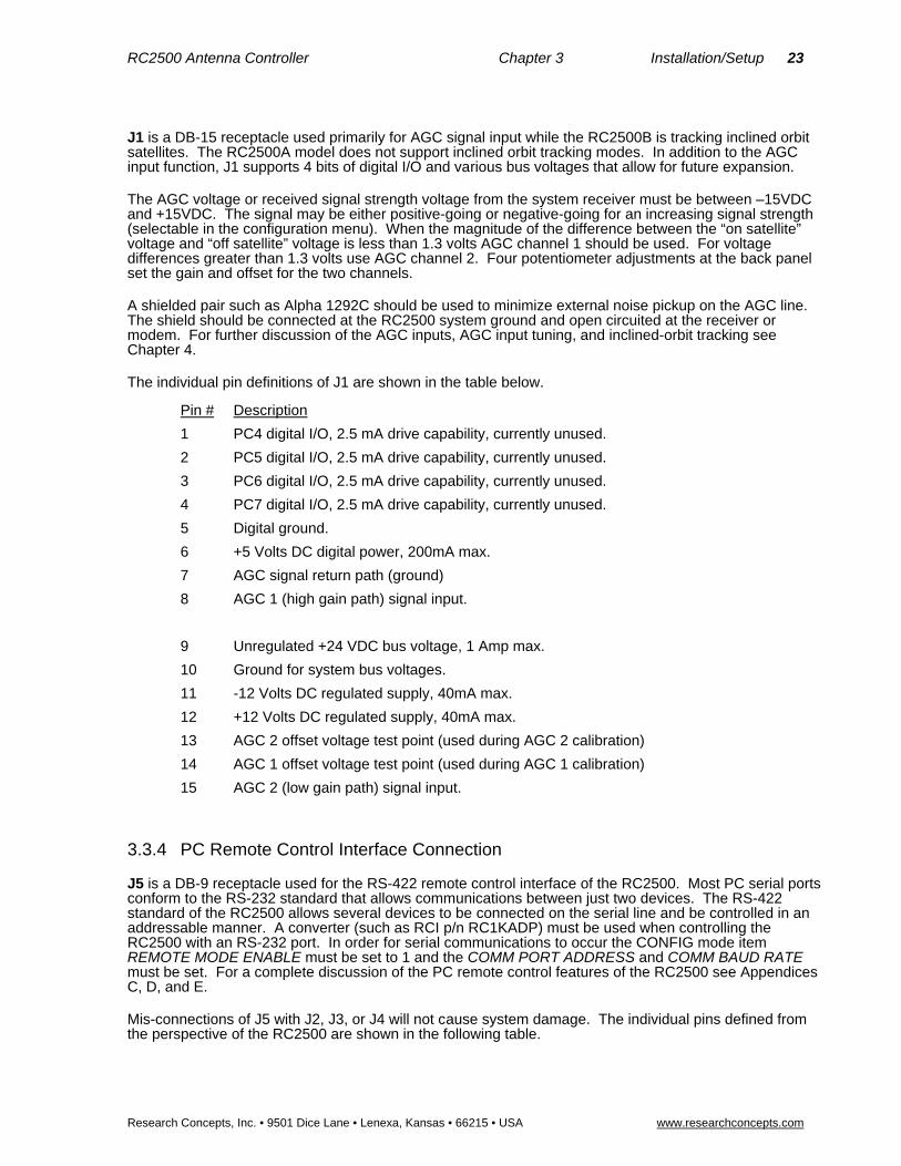
J1 is a DB-15 receptacle used primarily for AGC signal input while the RC2500B is tracking inclined orbit satellites. The RC2500A model does not support inclined orbit tracking modes. In addition to the AGC input function, J1 supports 4 bits of digital I/O and various bus voltages that allow for future expansion.
The AGC voltage or received signal strength voltage from the system receiver must be between –15VDC and +15VDC. The signal may be either positive-going or negative-going for an increasing signal strength (selectable in the configuration menu). When the magnitude of the difference between the “on satellite” voltage and “off satellite” voltage is less than 1.3 volts AGC channel 1 should be used. For voltage differences greater than 1.3 volts use AGC channel 2. Four potentiometer adjustments at the back panel set the gain and offset for the two channels.
A shielded pair such as Alpha 1292C should be used to minimize external noise pickup on the AGC line. The shield should be connected at the RC2500 system ground and open circuited at the receiver or modem. For further discussion of the AGC inputs, AGC input tuning, and inclined-orbit tracking see Chapter 4.
The individual pin definitions of J1 are shown in the table below.
Pin # Description
1 PC4 digital I/O, 2.5 mA drive capability, currently unused.
2 PC5 digital I/O, 2.5 mA drive capability, currently unused.
3 PC6 digital I/O, 2.5 mA drive capability, currently unused.
4 PC7 digital I/O, 2.5 mA drive capability, currently unused.
5 Digital ground.
6 +5 Volts DC digital power, 200mA max.
7 AGC signal return path (ground)
8 AGC 1 (high gain path) signal input.
9 Unregulated +24 VDC bus voltage, 1 Amp max.
10 Ground for system bus voltages.
11 -12 Volts DC regulated supply, 40mA max.
12 +12 Volts DC regulated supply, 40mA max.
13 AGC 2 offset voltage test point (used during AGC 2 calibration)
14 AGC 1 offset voltage test point (used during AGC 1 calibration)
15 AGC 2 (low gain path) signal input.
3.3.4 PC Remote Control Interface Connection
J5 is a DB-9 receptacle used for the RS-422 remote control interface of the RC2500. Most PC serial ports conform to the RS-232 standard that allows communications between just two devices. The RS-422 standard of the RC2500 allows several devices to be connected on the serial line and be controlled in an addressable manner. A converter (such as RCI p/n RC1KADP) must be used when controlling the RC2500 with an RS-232 port. In order for serial communications to occur the CONFIG mode item REMOTE MODE ENABLE must be set to 1 and the COMM PORT ADDRESS and COMM BAUD RATE must be set. For a complete discussion of the PC remote control features of the RC2500 see Appendices C, D, and E.
Mis-connections of J5 with J2, J3, or J4 will not cause system damage. The individual pins defined from the perspective of the RC2500 are shown in the following table.

24 RC2500 Antenna Controller Chapter 3 Installation/Setup
Research Concepts, Inc. • 9501 Dice Lane • Lenexa, Kansas • 66215 • USA www.researchconcepts.com
Pin # Description
1 Nc
2 Nc
3 Receive.
4 Transmit.
5 Nc
6 Transmit return.
7 Nc
8 Nc
9 Receive return.
3.4 Software Configuration Once the cabling between the RC2500 and the position sensors and the RC2500 and the A.I.U has been completed, certain configuration items should be set for optimum performance. This section describes how to set these parameters in the configuration mode of the RC2500. For a discussion of how to enter CONFIG mode see Chapter 2.
Many of the following items are only visible from CONFIG mode when “Expert Access” has been enabled. To enable expert access, refer to Section 2.5 and Appendix A.
3.4.1 Polarization Equipment Code
Depending on the application, several different feed configurations may be possible. If the antenna has a dual-port feed that will simultaneously receive vertical and horizontal polarization signals, only a single feed position must be stored for each satellite. A single port feed requires that two positions, vertical and horizontal be stored for each satellite position. If a non-moving feed is in place, or if you are working with circularly polarized signals, there will be no requirement for positioning of the feed. In this third case there will be no displayed angle for a polarization axis on the RC2500 display.
Determine your feed type. In CONFIG mode scroll down to the item POL CONTROL EQUIPMENT CODE. At the prompt, enter 0 for a fixed feed or a circularly polarized feed, enter 1 for a single-port feed, or enter 2 for a dual port feed.
3.4.2 Reversing the Resolver Sense Direction.
The A.I.U. should already have been wired such that the axes are all moving in the correct direction with local jog controls if any.
The resolver type position sensors wired as in the table found in the resolver installation section should result in the sensed position changing in the following manner when the antenna is moved.
Azimuth CW antenna movement (as viewed by an observer located above the antenna) must result in an increasing sensed position.
Elevation UP antenna movement must result in an increasing sensed position.
When the controller’s POL CW key is depressed, the sensed polarization position must increase.
RC2500 Antenna Controller Chapter 3 Installation/Setup 25
Research Concepts, Inc. • 9501 Dice Lane • Lenexa, Kansas • 66215 • USA www.researchconcepts.com
If the geometry of the installation results in position change in the incorrect direction, the CONFIG mode items REVERSE AZIMUTH SENSOR DIRECTION, REVERSE ELEVATION SENSOR DIRECTION, REVERSE POLARIZATION SENSOR DIRECTION may be used to correct the condition without making a wiring change. If any given axis requires a reversal, set its reversal CONFIG mode item to 1.
3.4.3 Fast and Slow Speed Setting
In manual mode, one of two speeds may be selected by toggling the “Speed” key on the keypad of the RC2500. Auto moves proceed at fast speed until the position of the active axis is within The AZ/EL FAST SLOW THRESHOLD count value. One “count” is equivalent to about 0.0055° of angle(360° ÷ 216). At this point, the system shifts to slow speed until the measured position is within the COAST THRESHOLD count value for a given axis. The drive then shuts down and the antenna is allowed to coast to a stop. If the antenna stops with a position count error greater than MAX POSITION ERROR , the controller will wait AZ/EL SLOW DEADBAND number of mSec and a retry will be attempted. This cycle will repeat until the antenna arrives within the target zone or until it has performed the pre-stored number of AZ/EL AUTO RETRY ATTEMPTS. These parameters and others are visible from the CONFIG menu only when “Expert Access” is enabled and the AZ/EL/POL DRIVE OPTIONS parameter has been set to 1. These items are described in detail in Chapter 5.
There are two different slow speed systems available on the RC2500. The first system simply has a relay driver output that selects one of two speeds. These two speeds should be adjusted to the desired level at the A.I.U. This system is present on the Vertex 7134 outdoor box. There is no fine speed adjustment in the RC2500 for this case.
In the second speed control scheme, the Harris 9135 outdoor box receives a pulse train from the indoor unit that is converted to a DC level. This DC level controls the speed of the motors. As the pulse train “on” duty cycle approaches 100%, the speed of the motor approaches the fast preset in the drive module. As the pulse train “on” duty cycle approaches 0%, the speed of the motor approaches the slow preset in the drive module. “Fast” speed is achieved by simply keeping pulse width at 100%.
For the RC2500/9135, the user sets the slow speed for each axis independently by entering a slow speed code at the AZIM SLOW SPEED CODE and ELEV SLOW SPEED CODE prompts in CONFIG mode. The Speed Code determines the duty cycle of a pulse width modulated waveform. The outdoor unit low-pass-filters this waveform and produces a motor speed proportional to the duty cycle.
After a system reset, the slow speed codes for azimuth and elevation are set to 128. This should produce a speed roughly half-way between the minimum and maximum speeds set in the A.I.U. Determine your required slow speed by changing the speed codes for each axis and trying it.
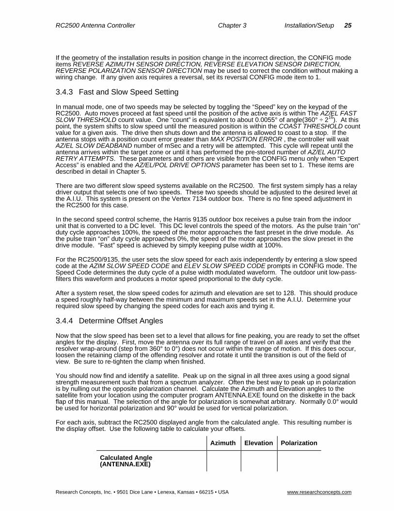
3.4.4 Determine Offset Angles
Now that the slow speed has been set to a level that allows for fine peaking, you are ready to set the offset angles for the display. First, move the antenna over its full range of travel on all axes and verify that the resolver wrap-around (step from 360° to 0°) does not occur within the range of motion. If this does occur, loosen the retaining clamp of the offending resolver and rotate it until the transition is out of the field of view. Be sure to re-tighten the clamp when finished.
You should now find and identify a satellite. Peak up on the signal in all three axes using a good signal strength measurement such that from a spectrum analyzer. Often the best way to peak up in polarization is by nulling out the opposite polarization channel. Calculate the Azimuth and Elevation angles to the satellite from your location using the computer program ANTENNA.EXE found on the diskette in the back flap of this manual. The selection of the angle for polarization is somewhat arbitrary. Normally 0.0° would be used for horizontal polarization and 90° would be used for vertical polarization.
For each axis, subtract the RC2500 displayed angle from the calculated angle. This resulting number is the display offset. Use the following table to calculate your offsets.
Azimuth Elevation Polarization
Calculated Angle (ANTENNA.EXE)

26 RC2500 Antenna Controller Chapter 3 Installation/Setup
Research Concepts, Inc. • 9501 Dice Lane • Lenexa, Kansas • 66215 • USA www.researchconcepts.com
Azimuth Elevation Polarization
RC2500 Displayed Angle
Difference( DISPLAY OFFSET)
Once this has been accomplished, enter the differences in the controller’s AZIM DISPLAY OFFSET, ELEV DISPLAY OFFSET, and POL DISPLAY OFFSET CONFIG mode items as appropriate. Return to manual mode. The RC2500 should now display the correct angles to the satellite.
3.4.5 Programming Satellites
Now we are ready to program satellites into the controller’s memory. All satellites are programmed into memory via SETUP mode. In SETUP mode you may jog the antenna in azimuth and elevation to peak up on a satellite, specify the satellite name and jog the polarization to assign H and V polarization values (if appropriate). This information is retained in the controller's non-volatile memory. Later, the user can automatically position the antenna on a satellite which has previously been programmed into memory by invoking the AUTO mode and using the SCROLL UP and SCROLL DOWN keys followed by the ENTER key to select the satellite.
SETUP mode is straightforward. If you wish to assign a satellite name that is not in the list, the USER entry in the satellite name list should be selected. The user is then prompted to enter an alphanumeric string using the SCROLL UP, SCROLL DOWN, and ENTER keys.
After the satellite name has been selected, you are prompted to enter in the satellite's longitude position. If the satellite name came from the controller’s internal list, you are presented with a longitude value also from the controller's internal list. The range of longitude values accepted by the controller ranges from 0 to 180 West and 0 to 180 East. Satellites located over North America have West longitude values. Satellites located over Asia have East longitude values. Some Intelsat literature gives satellite longitude values in a range of 0 to 359. In this scheme, values from 0 to 180 correspond to East longitudes. Values from 180 to 359 correspond to West longitudes. To convert from the Intelsat scheme to the scheme used by the controller, a simple example is presented. If the satellite longitude is specified as 325 degrees in the Intelsat scheme, to convert to the value needed for entry into the controller, calculate 360 - 325 (= 35). The value entered into the controller would then be 35.0 West.
Since your antenna is already pre-positioned on a satellite from the previous step, you may want to proceed into setup and store this satellite position. Note the exact AZ, EL and POL positions stored for this satellite on the Worksheet located in the back of this manual. It is recommended that you first program in a pair of satellites (noting the stored positions) and then use the AUTO mode to repeatedly position the antenna on one satellite and then the other. This will exercise the controller, actuators, mount, and position sensors as well as the positioning algorithm.
3.4.6 Setting AZ/EL/POL Drive Parameters
Now is a good time to modify the CONFIG mode items that govern the positioning of the antenna. These items were described in the section on fast and slow speed setting. You will also find a detailed discussion of these items in the CONFIG mode section of Chapter 5. All of these variables have default values that may or may not be appropriate for your antenna system. In the following discussion, remember one “count” is equivalent to 0.005493° of angle (360° ÷ 216) and DEADBANDS are measured in milli-Seconds (1/1000th of a Second).
Enter CONFIG mode and make sure EXPERT ACCESS is enabled and AZ/EL/POL DRIVE OPTIONS is enabled. An important item to determine for a given antenna system is the amount of coasting that is present when the drive shuts down from slow speed. To determine this, for the azimuth axis, Set AZ/EL FAST SLOW THRESHOLD to 1000, AZ/EL AUTO RETRY ATTEMPTS to 2, AZ/EL SLOW DEADBAND to 5000, AZIM COAST THRESHOLD & ELEV COAST THRESHOLD and AZIM MAX POSITION ERROR to 1. Move back and forth between the two previously stored satellites. With these settings, the antenna will move to the target position, shut off the drive at the target position, wait 5 Seconds, and then attempt to move back toward the target position. During this 5 second wait period, note how far the antenna traveled beyond the target position. Perform the auto-move several times from both directions. Average the readings taken. Divide this value (in degrees) by 0.005493 counts/degree. Enter this new value at the AZIM COAST Threshold prompt. This should result in the antenna coasting to a stop very near the target position.

RC2500 Antenna Controller Chapter 3 Installation/Setup 27
Research Concepts, Inc. • 9501 Dice Lane • Lenexa, Kansas • 66215 • USA www.researchconcepts.com
You may perform the same steps for the Elevation and Polarization axes to determine ELEV COAST THRESHOLD and POL COAST THRESHOLD.
Once the coast factors have been determined for the three axes, note the values you found in the table below:
Azimuth Elevation Polarization
Coast Threshold (counts)
AZIM MAX POSITION ERROR and ELEV MAX POSITION ERROR for normal operations can be set to 1/10th of a 3dB beamwidth converted to “counts”. Determine your 3dB beamwidth from the manufacturer’s data, divide the angle in degrees by 10 and then by 0.005493 degrees/count. Enter this value into the two CONFIG mode items . POL MAX POSITION ERROR may be returned to the default value of 10. This much error represents a theoretical cross-pol isolation of about –60 dB, much better than typical commercial feeds. These values are merely suggestions, you are free to make the CONFIG items larger or smaller than the calculated values.
Return AZ/EL FAST SLOW THRESHOLD to 400, AZ/EL AUTO RETRY ATTEMPTS to 3, AZ/EL SLOW DEADBAND to 2000 POL FAST SLOW THRESHOLD to 400, POL AUTO RETRY ATTEMPTS to 3, POL SLOW DEADBAND to 2000, their default values. These may be modified later for increased performance.
The CONFIG mode items AZ/EL FAST DEADBAND and POL FAST DEADBAND are the length of time in mSec that the controller will wait between opposite FAST motions for the given axis. These values allow for a coast-to-stop time and minimize wear on the mechanical components. These may remain at their default values.
Once the drive options have been set to values appropriate for your system (and entered into the table on the back page of this manual, you may want to disable the AZ/EL/POL DRIVE OPTIONS item to protect them from inadvertent changes later.
After the operation of the system has been verified by testing with two geostationary satellites, the rest of the satellites may be programmed in following the procedure in SETUP mode.
3.4.7 Simultaneous Azimuth and Elevation Movement
The RC2500 has the capability to move the azimuth and elevation axis actuators simultaneously during AUTO mode moves. The use of this feature is subject to the limitations in the A.I.U. If the A.I.U. is capable of driving both the azimuth and elevation axes simultaneously, Auto moves will take less time if this feature is enabled. Turn on this feature by going to the CONFIG mode SIMULTANEOUS AZ/EL ENABLE item and keying in 1 followed by the ENTER key.

28 RC2500 Antenna Controller Chapter 3 Installation/Setup
Research Concepts, Inc. • 9501 Dice Lane • Lenexa, Kansas • 66215 • USA www.researchconcepts.com
3.4.8 Jammed Sensing Configuration
Setting the Jammed Sensing
Version 1.33 makes it possible to customize the jammed sensing system for each axis. Jammed errors are explained in section 5.6. The AZ/EL Fast Deadband and the Pol Fast Deadband screens in the CONFIG mode are used to configure the jammed sensing system. The deadband screens are also still used to customize the deadband as discussed in section 5.8.7.
Figure-A:
The two last numbers configure the jammed sensing. The example in Figure-A shows the jammed sensing set to ‘45’. The first of the two numbers (in this case 4) sets the number of seconds before the software checks for a jammed error. The second number (in this example 5) sets the number of counts that are required to avoid a jammed error.
Using the example in Figure-A, when a drive command is first given, the controller initially waits 4 seconds before checking for a jammed error. After the initial 4 second wait, the controller begins to check for a jammed error during the next 4 seconds. During this time, the controller checks to see if the counts changed by a quantity of 5. If the antenna has moved at least 5 counts in the 4 second period, then no error occurs. If the antenna moved less than 5 counts in the 4 second period, then a jammed error occurs. The controller continually repeats this procedure throughout the movement.
Disabling Jammed Sensing
Jammed sensing can be disabled by setting the last digit to zero. For example, Figure-A shows a setting of ‘45’. If the number was changed to ‘40’ jammed sensing would be disabled.

RC2500 Antenna Controller Chapter 3 Installation/Setup 29
Research Concepts, Inc. • 9501 Dice Lane • Lenexa, Kansas • 66215 • USA www.researchconcepts.com
3.5 Installation and Setup Checklist This section gives a summary of the installation and configuration procedure outlined in this chapter. The summary is presented in the form of a checklist.
1. Before power is applied, verify that the line voltage is correct. Check the line voltage level displayed in the window of the power entry module.
2. Make sure that the memory has been cleared. Familiarize yourself with the menu system.
3. Make the required electrical connections. A shielded cable must be used for the position sensors and the shield must be connected at the back of the controller and not at the antenna. Make sure connections to the A.I.U. are correct. Shielded cable is also recommended for this connection.
4. Determine the feed arrangement and set the Polarization Equipment code.
5. Change the sensor directions for Az, El, and/or POL if the geometry of the installation requires it.
6. Verify that fast and slow speeds are adequate.
7. Locate and peak up on a Satellite, verify its identity and longitude from a current satellite guide. Make sure that the polarization axis is peaked as well.
8. Using the ANTENNA.EXE program, determine the azimuth and elevation angles to the satellite from your location. Use these angles to determine the azimuth and elevation offset angles to enter in to CONFIG mode. Set the appropriate polarization offset.
9. Go to SETUP mode and program in two satellites of interest using ANTENNA.EXE and the display of the RC2500 to find them.
10. Determine the dynamic coast, thresholds, and deadbands for the antenna system.
11. Program in the remainder of the Satellites of interest using ANTENNA.EXE and the display of the RC2500 to find them
12. Enable simultaneous azimuth and elevation movement in AUTO mode if the equipment in the A.I.U. will support it. Verify Auto moves between satellites stored in memory

30 RC2500 Antenna Controller Chapter 4 Inclined Orbit Satellites
Research Concepts, Inc. • 9501 Dice Lane • Lenexa, Kansas • 66215 • USA www.researchconcepts.com
Chapter 4 – Inclined Orbit Satellites There are multiple versions of the RC2500 antenna controller that operate with a variety of antenna types. These controller versions rare grouped into two categories, the RC2500A and the RC2500B. The difference between the two groups is the ability of the ‘B’ models to track inclined orbit satellites. The ‘A’ models do not have this capability. This chapter describes the characteristics of inclined orbit satellites and the tracking algorithms available on the RC2500B. The chapter begins with a tutorial on inclined orbit satellite operation, and continues with a description of the controller's tracking algorithms. It concludes with a section that guides the user through the hardware and software configuration procedure which must be performed prior to initiating a track on an inclined orbit satellite.
4.1 Geostationary and Inclined Orbit Satellites
To successfully track inclined orbit satellites with the RC2500B it is necessary to become somewhat familiar with the characteristics of an inclined orbit satellite's apparent motion as seen by the antenna. This section briefly reviews the orbital geometry of geostationary satellites, and then discusses inclined orbit satellites.
A geostationary satellite appears fixed in space to an observer at any point on the earth. In reality, the earth is rotating about its axis, and the satellite appears to be stationary because it is orbiting the earth in the earth's equatorial plane with a period identical to the earth's rate of rotation. The earth's equatorial plane is the plane defined by the earth's equator. Please refer to figure 4.1.
Many forces act on a satellite in geostationary orbit that tend to tilt the satellite's orbital plane away from the earth's equatorial plane and to pull the satellite out of its assigned longitudinal position. These forces are due to the gravitational attraction of the moon (which also gives rise to ocean tides) and the nonspherical earth. A discussion of these forces is beyond the scope of this presentation. A geostationary satellite must expend propellant to perform station-keeping maneuvers to maintain an orbit at the proper longitudinal position within the earth's equatorial plane.
East-West station-keeping maneuvers are performed to maintain the satellite's longitudinal position and North-South station-keeping maneuvers are performed to keep the satellite's orbital plane aligned with the earth's equatorial plane. Between 20 and 40 percent of the satellite's launch weight is due to station-keeping propellant. A satellite's design life is determined by the amount of station-keeping fuel onboard. A satellite is sometimes allowed to drift into an inclined orbit to extend its operational life. For a geostationary satellite, approximately 90 percent of the propellant is expended for North-South station-keeping activities. If North-South station-keeping ceases the operational life of the satellite may be greatly extended.
The orbital plane of an inclined orbit satellite is 'inclined' with respect to the earth's equatorial plane. Note that in figure 4.1 the inclination angle between the inclined orbit satellite's orbital plane and the earth's equatorial plane is greatly exaggerated. Typical inclination angles are less than 10 degrees. When satellite North-South station-keeping activities are suspended, the inclination of the satellite's orbit increases by approximately 0.9 degrees per year. Whereas a geostationary satellite appears fixed in space, the apparent position of a satellite in an inclined orbit varies with time.
If an inclined orbit satellite could be viewed by an observer located at the center of the earth, the apparent motion of the inclined orbit satellite would be a figure eight centered on the earth's equatorial plane. The motion of the satellite is periodic, which means that the figure eight pattern repeats itself. The period of the motion is 23 hours, 56 minutes, and 4 seconds. To an observer located at the center of the earth, the angle subtended by the figure eight pattern from North to South (i.e. height of the figure '8') is twice the inclination angle and the angle subtended by the figure eight pattern from East to West (i.e. width of the figure '8') is approximately the inclination angle (in degrees) squared divided by 115.
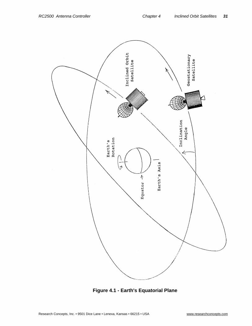
RC2500 Antenna Controller Chapter 4 Inclined Orbit Satellites 31
Research Concepts, Inc. • 9501 Dice Lane • Lenexa, Kansas • 66215 • USA www.researchconcepts.com
Figure 4.1 - Earth's Equatorial Plane
32 RC2500 Antenna Controller Chapter 4 Inclined Orbit Satellites
Research Concepts, Inc. • 9501 Dice Lane • Lenexa, Kansas • 66215 • USA www.researchconcepts.com
The apparent motion is slightly greater and somewhat skewed when viewed from the surface of the earth. The exact shape of the pattern varies with the longitudinal position of the satellite and the place on the earth from which the satellite motion is viewed. To estimate the height and width of an inclined orbit satellite's motion as viewed from the surface of the earth, a good approximation is to multiply the results of the equations above by 1.2.
Examination of these relationships show that the figure eight pattern is much taller than it is wide. For example, if the orbital plane of a satellite is inclined with respect to the earth's equatorial plane by 5 degrees, the apparent height and width of the figure eight pattern of the satellite's apparent motion as viewed from the surface of the earth is:
Height (North to South): 1.2 * 2 * 5 = 12 degrees
Width (East to West): (1.2 * 5 * 5) / 115 = 0.26 degrees
This example shows that the apparent motion of the satellite is practically a straight line. This knowledge of the satellite's apparent motion as viewed by the antenna is exploited by the RC2500B tracking antenna controller.
The 23 hour, 56 minute, and 4 second period of the satellite's apparent motion is referred to as a sidereal day. A sidereal day is the time that it takes the earth to complete exactly one revolution. The '24 hour' solar day is the period of time that it takes the sun to reach the same point in the sky. The solar day is longer than the sidereal day because the earth is in orbit around the sun and the earth must rotate more than 360 degrees for the sun to reach the same point in the sky.
Sidereal time refers to the time reference used to record time during a sidereal day. A sidereal time clock would progress up to 23 hours, 56 minutes, 3 seconds and then wrap around to 0 hours, 0 minutes, 0 seconds. All sidereal times used by the RC2500B controller and referenced in this manual are in seconds.
The apparent motion of the satellite as seen by the antenna is at it greatest when the satellite is passing through the earth’s equatorial plane. The apparent motion of the satellite is zero at the endpoints of the figure eight pattern when the satellite appears to reverse direction.
4.2 RC2500B Tracking Algorithm The tracking algorithm used on the RC2500B can be divided into 3 distinct parts, or submodes - STEP_TRACK, PROGRAM_TRACK, and SEARCH. A TRACK_ERROR submode is also implemented. These submodes are summarized here to provide an overview of the tracking algorithm. The following sections will provide much greater detail. Notice that certain words are italicized in the following subsections. The italicized text refers to parameters which are specified by the user either at the time of system installation (via CONFIG mode), when a track is initiated (via SETUP mode), or once a track has been established (via the TRACK mode menu). The idea is to get the user familiar with the parameters which he or she must either specify or adjust. All of these parameters are described in more detail in later sections.
The TRACK submodes will be described in chronological order as seen by a user initiating a track on an inclined orbit satellite. A track is initiated from SETUP mode. The user peaks the antenna on the inclined orbit satellite, selects the satellite name, longitude, inclination and frequency band, and then sets the satellite's horizontal and vertical polarization positions. At this point the controller enters STEP_TRACK mode. Note that not all versions of the software support polarization control.
In the STEP_TRACK submode the controller periodically performs peakups on the inclined orbit satellite. It stores azimuth and elevation positions of these peaks in a track table in non-volatile memory. The track table divides the sidereal day into 48 time segments. Whenever the current sidereal time equals the starting time for one of the 48 time segments, a peakup occurs and the antenna azimuth and elevation values are stored into the appropriate position within the track table. The track table stores a map of the satellite's apparent motion as seen by the antenna.
During a step_track operation, the controller peaks the antenna by monitoring the received signal strength. Signal strength information is available to the controller via the AGC (automatic gain control) input. The AGC input accepts a DC signal generated by the AGC circuits of a satellite receiver, or by a beacon receiver. The AGC setup and configuration procedure is described in section 4.4.1.

RC2500 Antenna Controller Chapter 4 Inclined Orbit Satellites 33
Research Concepts, Inc. • 9501 Dice Lane • Lenexa, Kansas • 66215 • USA www.researchconcepts.com
The PROGRAM_TRACK submode is active whenever a satellite's track table contains valid satellite position data for the current time. When PROGRAM_TRACK is active the antenna smoothly tracks the satellite by interpolating between track table azimuth and elevation position entries. Once a complete track table has been established for a satellite, the controller will remain in the PROGRAM_TRACK submode.
The SEARCH submode is active when the satellite signal is lost and track table data is not available. In this submode the controller performs a search for the satellite in the region where it calculates the satellite will be found, based on its knowledge of the satellite's apparent motion. If the satellite is found while the controller is performing a search, the STEP_TRACK submode will receive control. If the satellite is not found while performing the search, the controller will wait Search Retry Interval minutes and perform another search. If while waiting for the Search Retry Interval to expire, the sidereal time advances to a time for which valid track table data is available, the PROGRAM_TRACK mode will become active.
The automatic search may be disabled via the Search Enable CONFIG mode item. If the automatic search is disabled, the user is simply prompted to position the antenna on the satellite and hit the ENTER key.
The TRACK_ERROR submode becomes active whenever an error occurs. Some of the errors which can occur are: antenna jammed, antenna limit reached while tracking, antenna runaway, track table data corrupted, system CONFIG data corrupted, or a peak limit error has occurred (while peaking the antenna the controller had to move too far - possibly peaking on an adjacent satellite). Errors are described in Chapter 7.
4.2.1 STEP_TRACK
In the STEP_TRACK submode, the controller will periodically jog the antenna in elevation and then azimuth to peak up the antenna's received signal strength. This step_track operation will be referred to as a peakup. The STEP_TRACK submode is active whenever there is no track table information available for the current sidereal time and a satellite signal is present.
When STEP_TRACK mode is active, two events can trigger a step track operation. The first is when the current sidereal time reaches a value that corresponds to one of the 48 track table entries. The second is when the controller calculates that the antenna pointing error exceeds the value specified by the user. The Max Track Error CONFIG mode item allows the user to specify the maximum tracking error in tenths of a dB.
The controller constantly calculates the antenna pointing error based on the following data: the apparent motion of the satellite (determined by the Inclination of the satellite’s orbital plane), the antenna's beamwidth (determined by the Antenna Size and the satellite frequency Band), and the length of time since the last peakup. To determine the peakup interval, the controller assumes that the satellite is always moving at its maximum velocity as seen by the antenna. The maximum velocity occurs when the satellite is passing through the earth’s equatorial plane. When the controller determines that in length of time since the last peakup occurred the satellite could have moved so far as to allow the antenna pointing error to exceed the Max Track Error specified by the user, a peakup will be initiated.
The size of the azimuth and elevation movements (or step sizes) for the step_track operation is also determined by the Max Track Error value. The step size corresponds to the angular movement of the antenna which would change the received signal strength by Max Track Error tenths of a dB. It is calculated based on the antenna's beamwidth and radiation pattern.
Reducing the Max Track Error value results in more frequent step_track operations with smaller step sizes. There are limits to how small the max track error may be. This is discussed in section 4.4.5 - Tracking Problems. Step_track operations will occur more frequently for satellites with larger orbital Inclination values, or with larger antenna sizes. For a given Antenna Size and satellite Inclination, step track operations will occur more frequently for Ku band transponders than for C band transponders. (The user is prompted to enter satellite Band data during setup.) For hybrid satellites (both C and Ku band), the TRACK menu system allows the user to switch bands.
The STEP_TRACK submode will pass control to these TRACK mode submodes on the following conditions:
PROGRAM_TRACK..receives control when the current sidereal time equals a time for which track table data is available.

34 RC2500 Antenna Controller Chapter 4 Inclined Orbit Satellites
Research Concepts, Inc. • 9501 Dice Lane • Lenexa, Kansas • 66215 • USA www.researchconcepts.com
SEARCH..receives control if the satellite signal is lost.
ERROR..receives control if any error is encountered.
4.2.2 PROGRAM_TRACK
When the PROGRAM_TRACK submode is active, the controller smoothly positions the antenna to azimuth and elevation positions derived from the track table, regardless of whether a satellite signal is present or not. The track table holds a map of the satellite's apparent motion as a function of sidereal time. The controller performs a linear interpolation between adjacent track table entries to determine the correct antenna position.
In PROGRAM_TRACK submode antenna movement occurs whenever the controller calculates that the error between the antenna's current position and the antenna's proper position as determined from the track table exceeds Max Track Error tenths of a dB. To determine the error between the current and calculated antenna position, the controller calculates the antenna beamwidth based on the Antenna Size and the frequency Band. If the Max Track Error parameter is decreased in value, the antenna pointing error will be less, but the antenna will move more often, which increases wear on the antenna actuators.
The PROGRAM_TRACK submode also periodically performs peakups (similar to STEP_TRACK submode) to check the accuracy of track table entries. If the discrepancy between the peakup position and the position stored in the track table is greater than that specified by the Max Track Error parameter, the update flag for each entry in the track table is set TRUE. The frequency at which these track table accuracy checks occur is determined by the Update Check parameter. The default Update Check interval is 33 hours, but can be changed by the user to any value in the range of 1 to 999 hours (via the TRACK MENU system).
If the current sidereal time reaches a value that corresponds to an entry in the track table whose update flag is set TRUE, and the current signal strength level indicates that a satellite signal is present, a peakup will occur, the track table entry will be updated, and the track table update flag is reset FALSE. If the satellite signal is not present the update flag remains set TRUE and the system will try again in 23 hours, 56 minutes, and 4 seconds. The user can view the contents of each track table entry and examine the present state of the update flag. In addition the user can invoke the Force Update or Reset Update functions to force the update flag for each entry in the track table to be either set TRUE or reset FALSE, respectively. These functions are accessible via the TRACK MENU system, which is described in more detail in section 5.4.
The PROGRAM_TRACK submode will pass control to the other TRACK mode submodes under the following circumstances:
STEP_TRACK..receives control when the current sidereal time reaches a value for which there are no valid track table entries and a valid satellite signal is present.
SEARCH..receives control when the current sidereal time reaches a value for which there are no valid track table entries and a valid satellite signal is not present.
ERROR..receives control when any error is encountered.
4.2.3 Intelli-Search
The SEARCH submode receives control whenever the satellite signal is lost and the track table does not contain antenna azimuth and elevation position data for the current sidereal time. Whenever the SEARCH submode is active the controller periodically performs a search over the region where the controller has calculated that the satellite will be found. The Intelli-Search algorithm determines the extent of the search region based on the Satellite Longitude, the Antenna Latitude and Antenna Longitude, the antenna beamwidth (as calculated from the Antenna Size and frequency Band), and the Elevation and Azimuth Scale Factors.
The Azimuth and Elevation scale factors are fixed and refer to the mapping of antenna azimuth and elevation position counts to antenna azimuth and elevation angles, respectively. The 360° (or 2*PI) angular region measured by the resolvers and on-board resolver-to-digital converters is divided into 216 (or 65,536) discrete positions. The azimuth and elevation scale factors are the number of counts in one radian of angle for the two axes. This value is 10,430 counts/radian for both Az and El. One ‘count’ is equivalent to 360 / 65,536 = 0.005493°. This number represents the resolution of the angular

RC2500 Antenna Controller Chapter 4 Inclined Orbit Satellites 35
Research Concepts, Inc. • 9501 Dice Lane • Lenexa, Kansas • 66215 • USA www.researchconcepts.com
measurement system of the RC2500. The RC2500 can position an antenna to no better than within 0.005493° of the target position. The actual positioning performance will depend strongly on the mechanical and electrical drive components of the system. The accuracy of the system depends almost solely upon the accuracy of the resolvers used. The standard resolvers shipped with the RC2500 have + 7 arc-minute accuracy or + 0.11667°.
The use of the Intelli-Search algorithm relieves the user of the task of having to specify the controller's search region. Other tracking antenna controllers limit the search to a box shaped region and force the user to determine the boundaries of the search region, which is often a trial and error process. Please refer to figure 4.2 on the following page. If the box shaped region specified by the user is too small the controller may not search the entire region where the satellite's apparent motion takes it, and for some segments of the satellite's movement, the controller may not be able to find the satellite. If the box search region is too large, the controller may find an adjacent satellite. If the search region is not centered properly, both of the error conditions described above could occur.
The Intelli-Search algorithm calculates the shape of the search region based on easily determined physical data supplied by the user, and information derived from the antenna positions and longitudes of the geostationary satellites in the vicinity of the inclined orbit satellite which is being tracked. In most cases the search region is shaped like a parallelogram. The long dimension of the parallelogram is calculated based on the satellite Inclination angle specified by the user when the track is initiated from SETUP mode. The width (or short dimension) of the parallelogram is specified by the Search Width parameter entered via CONFIG mode. The Search Width has a range of values of 1 to 10, with 1 specifying the narrowest search window and 10 specifying the widest window. The default value of 3 is adequate for most situations.
If a satellite signal is found during a search, the controller switches to the STEP_TRACK submode. If a satellite signal is not found during the search, the unit waits awhile and then performs another search. If during the wait the sidereal time advances to a value for which there is valid track table data, the controller will switch to the PROGRAM_TRACK mode. The wait period between successive searches is determined by the value of the Search Retry Interval parameter. The default value of this parameter is 10 minutes, but it can be changed to any value between 0 and 999 minutes via the TRACK menu.
The search consists of successive sweeps separated from one another by an angle corresponding to a 2 dB rolloff of the antenna pattern. The antenna pattern is calculated based on the Antenna Size and frequency Band. The controller will sweep in azimuth, increment the elevation angle, and then sweep again in azimuth. This will continue until the entire search region has been covered. The automatic search may be enabled or disabled via the Search Enable CONFIG mode item. When the automatic search is disabled, the user is prompted to manually jog the antenna onto the desired satellite, and then hit the ENTER key.
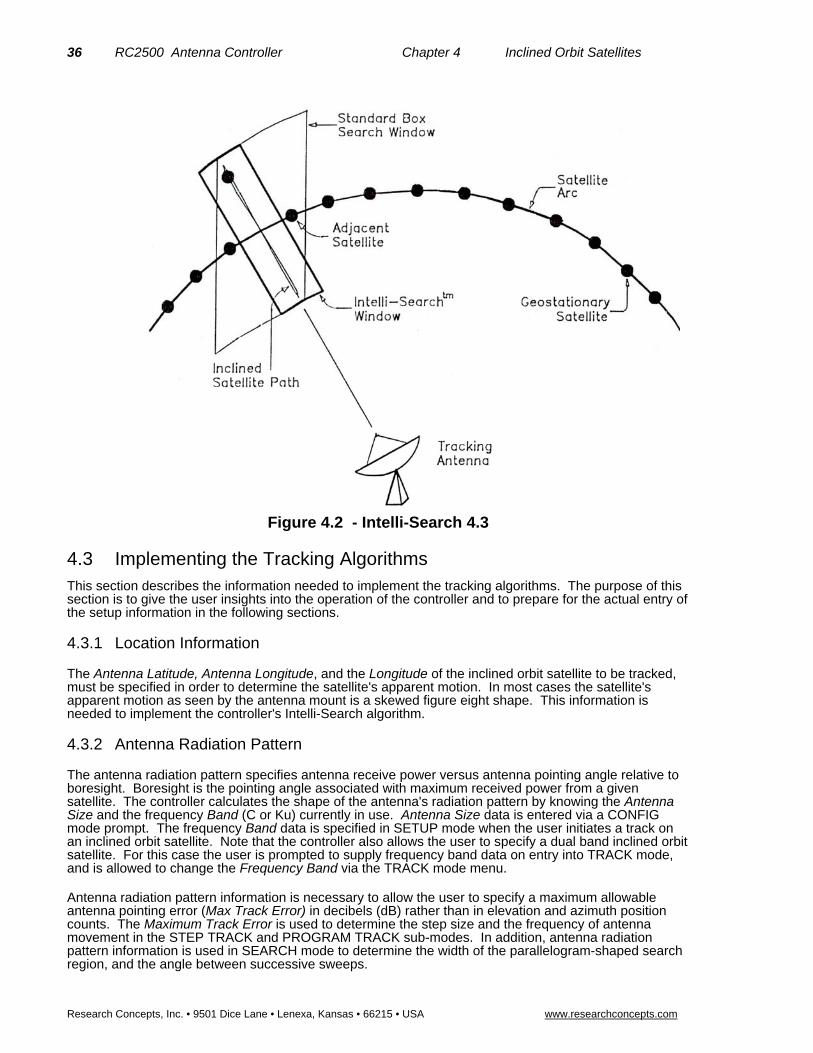
36 RC2500 Antenna Controller Chapter 4 Inclined Orbit Satellites
Research Concepts, Inc. • 9501 Dice Lane • Lenexa, Kansas • 66215 • USA www.researchconcepts.com
Figure 4.2 - Intelli-Search 4.3
4.3 Implementing the Tracking Algorithms
This section describes the information needed to implement the tracking algorithms. The purpose of this section is to give the user insights into the operation of the controller and to prepare for the actual entry of the setup information in the following sections.
4.3.1 Location Information
The Antenna Latitude, Antenna Longitude, and the Longitude of the inclined orbit satellite to be tracked, must be specified in order to determine the satellite's apparent motion. In most cases the satellite's apparent motion as seen by the antenna mount is a skewed figure eight shape. This information is needed to implement the controller's Intelli-Search algorithm.
4.3.2 Antenna Radiation Pattern
The antenna radiation pattern specifies antenna receive power versus antenna pointing angle relative to boresight. Boresight is the pointing angle associated with maximum received power from a given satellite. The controller calculates the shape of the antenna's radiation pattern by knowing the Antenna Size and the frequency Band (C or Ku) currently in use. Antenna Size data is entered via a CONFIG mode prompt. The frequency Band data is specified in SETUP mode when the user initiates a track on an inclined orbit satellite. Note that the controller also allows the user to specify a dual band inclined orbit satellite. For this case the user is prompted to supply frequency band data on entry into TRACK mode, and is allowed to change the Frequency Band via the TRACK mode menu.
Antenna radiation pattern information is necessary to allow the user to specify a maximum allowable antenna pointing error (Max Track Error) in decibels (dB) rather than in elevation and azimuth position counts. The Maximum Track Error is used to determine the step size and the frequency of antenna movement in the STEP TRACK and PROGRAM TRACK sub-modes. In addition, antenna radiation pattern information is used in SEARCH mode to determine the width of the parallelogram-shaped search region, and the angle between successive sweeps.

RC2500 Antenna Controller Chapter 4 Inclined Orbit Satellites 37
Research Concepts, Inc. • 9501 Dice Lane • Lenexa, Kansas • 66215 • USA www.researchconcepts.com
4.3.3 Real Time Clock
The controller contains a real time clock (powered by the same lithium battery that powers the controller's non-volatile memory) which is used to calculate the sidereal time. The period of the satellite's motion is one sidereal day. The controller maintains a track table which contains the satellite's azimuth and elevation positions as a function of sidereal time. The controller uses the time and date maintained by the real time clock to calculate the sidereal time. The user specifies the Time and Date via CONFIG mode prompts.
It is important that the user not change the time value when the time changes from Standard Time to Daylight Savings Time. The satellite does not experience the time shift. If the time is changed forward or backward by one hour, the data in the program track table will no longer be correct. For this reason the user should not change the time as the time standard changes. If this causes confusion the time may be specified as Universal Coordinated Time (for known as Greenwhich Mean Time - GMT). Note that the real time clock used in the controller will properly account for leap years. The RC2500B tracking algorithm is year 2000 compliant.
4.3.4 Receiver AGC Signal
To implement the tracking algorithms, the controller requires an input signal, which indicates the strength of the received signal. Such a signal is generated within a satellite receiver or modem, and is referred to as an AGC signal. (AGC is the abbreviation for Automatic Gain Control.) On satellite receivers, this signal may also be referred to as a 'Signal Strength' or 'Tuning Meter' output. An AGC output typically varies in proportion to the received power of the transponder, which the receiver is currently tuned to.
The signal strength input is used to peak up the antenna while step tracking. The step tracking operation positions the antenna to maximize the received signal strength. Signal strength is also used to determine whether or not a satellite transponder is currently active. If the signal strength reading falls below a threshold set by the user, the controller assumes that a satellite signal is not present. If the satellite signal is lost while step tracking, the SEARCH sub-mode receives control. When the PROGRAM_TRACK sub-mode is active, the presence of a satellite signal governs whether or not track table update operations are performed. The procedures required to perform the controller setup for various receiver AGC configurations are covered in detail in the next section.
4.4 Configuring the Tracking System This section describes the procedures that the user must follow to configure the tracking system. The procedures for adjusting the AGC gain and offset pots, determining the AGC threshold parameters, and entering other CONFIG mode data pertaining to the tracking system, are all covered in this section.
4.4.1 AGC Adjustment and Configuration
The controller has the provision to process two channels of AGC information. This means that two receivers may be connected to the controller (one receiver is required). The two channels are referred to as AGC1 and AGC2. The controller chooses the stronger of the two as its AGC input. Each channel has separate gain and offset potentiometer adjustments. The installer uses the pots to transform the receiver's AGC signal swing into a range of values which is easily measured by the controller.
In addition to the potentiometers, there are three CONFIG mode items that are related to the AGC system. The three items are:
1. AGC Polarity Flag - This flag indicates to the controller whether a stronger satellite signal corresponds to a higher AGC voltage (positive polarity) or a lower AGC voltage (negative polarity). Both AGC channels must have the same polarity. Each AGC channel contains an internal pull down resistor. This means that if one of the AGC channels is unused, its input is pulled to ground. This can cause problems if the AGC Polarity Flag specifies negative polarity or if the AGC input range traverses zero volts. In these cases, an input of zero volts (ground potential) corresponds to a possible satellite signal. To account for these cases, the installer must adjust the offset pot of the unused channel such that it results in a measured signal strength near zero.
2. 2. AGC C Band Threshold - When the receiver is tuned to a C band satellite and the signal strength is above this value, it is assumed that a satellite signal is present. The same threshold is applied to both AGC channels.

38 RC2500 Antenna Controller Chapter 4 Inclined Orbit Satellites
Research Concepts, Inc. • 9501 Dice Lane • Lenexa, Kansas • 66215 • USA www.researchconcepts.com
3. 3. AGC K/L Band Threshold - This is similar to the C Band Threshold described above, except it pertains to Ku or L Band. If the signal strength is above this value when the receiver is tuned to a Ku or L band satellite, the controller assumes that a satellite signal is present.
The signal strength is displayed when MANUAL, TRACK, and SETUP modes are active. In TRACK, and SETUP modes, the signal strength of the AGC channel that corresponds to the strongest received satellite signal is displayed. In MANUAL mode, the signal strength of a user-selected channel can be displayed. The channel to be displayed is chosen by using the SCROLL UP/DOWN Keys. The AGC channel selected is noted by a 1: preceding the signal strength value for AGC1 and a 2: preceding the signal strength value for AGC2. Continuing to press the same SCROLL key will cycle through the selections of 1:, 2:, and S: . When the S: is displayed, the system selects the stronger of the two AGC inputs as in TRACK and SETUP modes.
Currently the AGC Channel Scroll feature is not supported
The signal strength is displayed as a number in the range of 0 to 1023. Note that in MANUAL, TRACK, and SETUP modes, the maximum signal strength that can be displayed is 999. A signal greater than 999 is displayed as '***'. The displayed value takes into account the setting of the AGC Polarity Flag. In other words, a greater signal strength value always corresponds to a large displayed signal value.
4.4.1.1 Single Receiver - Single Frequency Band Inclined Orbit Satellite AGC Setup
The following paragraphs describe the setup procedure for the simplest case - only one receiver and controller AGC input are used, and the user is tracking only C band (or only Ku or L band) inclined orbit satellites. The AGC will be adjusted to show a reading of 650 when on satellite and 75 when off satellite.
1. Align the antenna with a strong satellite (geostationary or inclined orbit) of the proper frequency band. Place a voltmeter on the receiver's AGC output, measure and record the voltage. In the description that follows, the term 'on satellite' will be used to refer to the antenna aligned with a strong satellite. Note the value below:
“On Satellite” AGC Voltage = .
2. Jog the antenna off of the satellite so the antenna is looking at empty sky. Measure and record the receiver's AGC voltage. In the description that follows, the term 'off satellite' will be used to refer to this case where the antenna is positioned well off of any satellite, looking at nothing. Note the value below.
“Off Satellite” AGC Voltage = .
3. At this point you may refer to the program diskette accompanying your RC2500 controller. On this diskette, among other programs, is one entitled: 2_5KAGC.EXE. This DOS program will perform the required ACG setup calculations and make recommendations as to the connections for the AGC. If you should choose this route, execute the program and skips steps 4 through 9 and go directly to step 10.
4. To manually determine the configuration of the AGC system, you will determine which AGC channel to use, determine the polarity of the AGC signal, and calculate the required Voffset value to be set on your RC2500. Briefly, the process is as follows: a) If the difference between the “On Satellite” Voltage and “Off Satellite” voltage is less than 1.3 volts, choose AGC1, otherwise choose AGC2. b) if the “On Satellite” Voltage is greater than the “Off Satellite” voltage choose positive AGC, otherwise choose negative AGC. c) The required Voffset is calculated from the equation below:
Where;
VS = is the “On Satellite” voltage noted above,
VN = is the “Off Satellite” voltage noted above,
For Positive AGC J=3.177, for Negative AGC J=1.823.
LVV
VKJ
VV
VV
NS
S
NS
Soffset
812812 .*.*
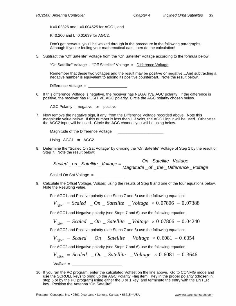
RC2500 Antenna Controller Chapter 4 Inclined Orbit Satellites 39
Research Concepts, Inc. • 9501 Dice Lane • Lenexa, Kansas • 66215 • USA www.researchconcepts.com
K=0.02326 and L=0.004525 for AGC1, and
K=0.200 and L=0.01639 for AGC2.
Don’t get nervous, you’ll be walked through in the procedure in the following paragraphs. Although if you’re feeling your mathematical oats, then do the calculation!
5. Subtract the “Off Satellite” Voltage from the “On Satellite” Voltage according to the formula below:
“On Satellite” Voltage - “Off Satellite” Voltage = Difference Voltage
Remember that these two voltages and the result may be positive or negative…And subtracting a negative number is equivalent to adding its positive counterpart. Note the result below.
Difference Voltage = __________________
6. If this difference Voltage is negative, the receiver has NEGATIVE AGC polarity. If the difference is positive, the receiver has POSITIVE AGC polarity. Circle the AGC polarity chosen below.
AGC Polarity = negative or positive
7. Now remove the negative sign, if any, from the Difference Voltage recorded above. Note this magnitude value below. If this number is less than 1.3 volts, the AGC1 input will be used. Otherwise the AGC2 input will be used. Circle the AGC channel you will be using below.
Magnitude of the Difference Voltage = _____________________
Using AGC1 or AGC2
8. Determine the “Scaled On Sat Voltage” by dividing the “On Satellite” Voltage of Step 1 by the result of Step 7. Note the result below:
Scaled On Sat Voltage = _____________
9. Calculate the Offset Voltage, Voffset, using the results of Step 8 and one of the four equations below. Note the Resulting value.
For AGC1 and Positive polarity (see Steps 7 and 6) use the following equation:
For AGC1 and Negative polarity (see Steps 7 and 6) use the following equation:
For AGC2 and Positive polarity (see Steps 7 and 6) use the following equation:
For AGC2 and Negative polarity (see Steps 7 and 6) use the following equation:
Voffset = _______________________
10. If you ran the PC program, enter the calculated Voffset on the line above. Go to CONFIG mode and use the SCROLL keys to bring up the AGC Polarity Flag item. Key in the proper polarity (chosen in step 6 or by the PC program) using either the 0 or 1 key, and terminate the entry with the ENTER key. Position the Antenna “On Satellite”.
07388.007806.0___ VoltageSatelliteOnScaledVoffset
VoltageDifferencetheofMagnitude
VoltageSatelliteOnVoltageSatelliteonScaled
____
_____
6354.06081.0___ VoltageSatelliteOnScaledVoffset
04240.007806.0___ VoltageSatelliteOnScaledVoffset
3646.06081.0___ VoltageSatelliteOnScaledVoffset

40 RC2500 Antenna Controller Chapter 4 Inclined Orbit Satellites
Research Concepts, Inc. • 9501 Dice Lane • Lenexa, Kansas • 66215 • USA www.researchconcepts.com
11. If the receiver's AGC has NEGATIVE polarity (results of Step 6 or the PC program), go to step 12. If the receiver's AGC has POSITIVE polarity, go to MANUAL mode and examine the signal strength for the AGC channel that was not selected in step 7 or by the PC program. (SCROLL UP or SCROLL DOWN until the channel number is displayed i.e. 2: ). If the signal strength reading for that channel is greater than 10, adjust the OFFSET pot for that channel until the signal strength reading for that channel is less than 10. To lower the displayed signal strength, turn the appropriate OFFSET pot clockwise. Proceed to step 13.
Currently the AGC Channel Scroll feature is not supported
12. If the receiver's AGC has NEGATIVE polarity (results of Step 6 or the PC program), go to MANUAL mode and examine the signal strength for the AGC channel that was not selected in step 7 or by the PC program. (SCROLL UP or SCROLL DOWN until the channel number is displayed i.e. 2: ). If the signal strength reading for that channel is greater than 10, adjust the OFFSET pot for that channel until the signal strength reading for that channel is less than 10. To lower the displayed signal strength value, turn the appropriate OFFSET pot counter-clockwise. Proceed to step 13.
Currently the AGC Channel Scroll feature is not supported
13. Connect the receiver's AGC output to the controller's AGC input (AGC1 or AGC2) chosen in Step 7 above or by the PC program. Be sure to connect the ground return of the controller to a ground on the receiver. See figure 3.1 and the discussion of section 3.3.3.
14. Using a voltmeter clip the black lead to the RC2500 J1 pin 7 and the red lead to J1 pin 14 if using AGC1 or J1 pin 13 if using AGC2. Adjust the OFFSET pot for the appropriate AGC channel until a reading of your calculated Voffset is obtained. (See Step 9 or the PC program) To increase the offset voltage, turn the OFFSET pot clockwise.
15. Adjust the gain pot for the appropriate AGC channel for a displayed signal strength of 650. To increase the displayed signal strength, turn the GAIN pot clockwise for Vs positive with positive AGC or when Vs is negative with negative AGC. Turn the Gain Pot counterclockwise for an increase in displayed signal strength for Vs positive with negative AGC or when Vs is negative with positive AGC.
16. Now, readjust the Offset pot to show a reading of Voffset on the voltmeter described in Step 15. Re-tweak the Gain pot for a displayed signal strength of 650. You may need to do this step 2 or three times to get the values as close as practical.
17. Jog the antenna off of the satellite until the picture is just barely visible. Note the signal strength value. Go to CONFIG mode and use the SCROLL keys to bring up either the AGC C Band Threshold item or the AGC K/L Band Threshold item, whichever is appropriate for the frequency band that the user has chosen to operate at (and has adjusted the pots at). Key in the signal strength value noted above. Terminate the entry with the ENTER key.
AGC Threshold = ________________
4.4.1.2 Single Receiver - Dual Frequency Band Inclined Orbit Satellite AGC Setup
The setup procedure described above was for the case where a single satellite receiver is connected to the controller, and the user is interested in tracking only satellites of a single frequency band (either C or Ku). A slight increase in complexity occurs if the user must be able to track both C and Ku band inclined orbit satellites. This is because the same AGC channel is used for both frequency bands, and therefore the OFFSET and GAIN pot adjustments for that channel must be made so as to accommodate both frequency bands. At the heart of the problem is the fact that the signal strength (as seen by the receiver's AGC circuits) will vary with the frequency band selected due to differences in antenna gain, LNB gain, and the differences in output power between C, Ku, and L band satellites.
The adjustment procedure for the dual band case is very similar to the single band case described above. The following paragraphs describe the modifications required to adapt the single receiver - single band procedure, to the single receiver - dual band case.
1. The procedure is similar to step 1 above except that the user should align the antenna with a strong C band and a strong Ku (or L) band satellite. The installer should then choose the largest of the two (or three) levels as the “On Satellite” voltage.
2. Similar to step 2 above except that both C and Ku (or L) band AGC voltages are obtained when the antenna is looking at nothing. The installer should then choose the smallest of the two (or three) levels as the “Off Satellite” voltage.

RC2500 Antenna Controller Chapter 4 Inclined Orbit Satellites 41
Research Concepts, Inc. • 9501 Dice Lane • Lenexa, Kansas • 66215 • USA www.researchconcepts.com
3. Follow steps 3 through 17 above.
4.4.1.3 Using Two AGC Channels
Connecting a second receiver to the controller is straightforward. The controller AGC input channel GAIN and OFFSET adjustments have enough range to handle any possible receiver AGC scheme, as long as the AGC level is between –15 VDC and +15 VDC. In step 7 of the adjustment procedure, the installer is instructed to select the controller AGC input channel based on the range of the receiver's AGC output. AGC input channel 1 is designed to handle 'small' AGC signal swings, and AGC input channel 2 is designed for 'large' AGC signal swings. There is enough adjustment range, however, so that either channel may be connected to any receiver AGC output.
If two receivers are used, both must have the same AGC polarity, and the GAIN and OFFSET pots of each channel must be adjusted so that the same threshold values are appropriate for each channel. The controller will use as its AGC input the stronger of the two signals. All pot adjustments will have to take place in MANUAL mode with the scroll keys setting a single displayed AGC channel. (SCROLL UP or SCROLL DOWN until the channel number is displayed i.e. 2: )
Currently the AGC Channel Scroll feature is not supported
4.4.1.4 Amplifier Gain vs. Frequency Characteristics
An amplifier's gain vs. frequency characteristic, or gain flatness, is the variation of the amplifier's gain with changing frequency. The ideal response is to have a flat gain characteristic (the gain does not vary with frequency). Amplifiers with poor gain flatness characteristics can cause problems for the tracker. This section describes a simple test (no equipment required) that the user can carry out to check the receiving system's gain flatness.
There are four places in a satellite receiving system that may have gain flatness problems that can affect the operation of the tracker. These are the LNB, the coaxial cable connecting the LNB to the receiver, line amps (or bullet amps) inserted in the 950 - 1750 MHz IF, and the receiver's IF or AGC stages. If a spectrum analyzer is connected into the receiver's block IF line, the gain flatness of the LNB and any line amps present can be observed. When the antenna is pointed away from any satellite, the spectrum analyzer displays the received noise, which should be constant with frequency. If the display is not a horizontal line then some gain variation with frequency is present.
To understand how a poor gain flatness characteristic can cause problems, remember that the purpose of the AGC input is to let the controller determine whether a satellite signal is present or not, and to provide relative signal strength information when peaking the antenna. A signal is assumed to be present whenever the AGC input is above the threshold level for whichever band - C or Ku or L - has been selected. When the receiver is tuned to various transponders, gain flatness problems could cause the AGC signal to be above the threshold, when in fact no satellite signal is present. For certain transponders, gain flatness problems could also cause the controller's AGC input scaling network to be saturated when the antenna is aligned with a strong satellite, making it impossible for the controller to detect changes in signal strength when attempting to peak the antenna.
To test the gain flatness of the satellite receiver, perform the following procedure. The procedure assumes a single receiver, single frequency band system.
Position the antenna well off of any satellite. Tune the receiver to each transponder. Make sure that the signal strength reading is below the threshold assigned via CONFIG mode.
Align the antenna with a strong satellite. Tune the receiver to each active transponder on the satellite. Make sure that the signal strength is well above the threshold and below 999.
If the system fails either of the tests above, then the user can either attempt to correct the problem by readjusting the GAIN and OFFSET pots (using the procedure outlined earlier), or by correcting the gain flatness problem. Most gain flatness problems can be traced to a problem with the coaxial cable connecting the antenna to the receiver (sometimes called a 'suck-out') or to bullet amplifiers. Some bullet amplifiers have been observed to have really terrible gain flatness characteristics.
To perform the above tests on a dual frequency band system, repeat the test for each frequency band. On a dual receiver system, simply perform the test on each receiver. On a dual frequency system the tests should be performed with the controller in MANUAL mode, so that there is no confusion as to which

42 RC2500 Antenna Controller Chapter 4 Inclined Orbit Satellites
Research Concepts, Inc. • 9501 Dice Lane • Lenexa, Kansas • 66215 • USA www.researchconcepts.com
AGC input channel the displayed signal strength reading corresponds to. (SCROLL UP or SCROLL DOWN until the desired channel number is displayed i.e. 2: ).
Currently the AGC Channel Scroll feature is not supported
4.4.2 CONFIG Mode Data
This section briefly describes each of the CONFIG mode items and how they relate to the tracking system. The names of CONFIG mode items appear in italics. The installer should go through this section and enter in the relevant data. Be sure to terminate each entry with the ENTER key. If an entry is terminated by depressing the SCROLL keys, the data entered by the user is not stored in non-volatile memory. After all of the data has been entered, the user should go through the data items again to verify that all entries were properly recorded.
The Remote Mode Enable, Comm Address, and Comm Baud Rate CONFIG mode items control the operation of the REMOTE mode system. If REMOTE mode is enabled, commands may be received via the serial port while tracking an inclined orbit satellite, and front panel control of polarization is disabled. While TRACK mode is active, a remote command received which specifies an azimuth or elevation movement will cause REMOTE mode to activate - no tracking occurs in REMOTE mode. A remote command which is received that does not involve azimuth or elevation movement, will be serviced by TRACK mode without disrupting the tracking operation in progress.
The Azim Slow Speed and the Elev Slow Speed codes are discussed in section 3.4.3. These speed codes should be initialized because all movement in TRACK mode occur at slow speed.
The Simultaneous Az/El Enable CONFIG mode item is not relevant in TRACK mode as no movements in TRACK mode occur about each axis simultaneously. This item is only applicable to movements that occur in AUTO mode.
For inclined orbit tracking, it is generally best to set the Max Position Error CONFIG mode item to 0.
The Time and Date are entered via CONFIG mode. The use of time and date information by the tracker is described in section 4.3.3. Note that once a track is established for a satellite the Time and Date should not be changed. If this is a problem, the user might set the Time and Date to Coordinated Universal Time (formally called Greenwich Mean Time - GMT). Please refer to section 4.3.3.
The AGC Polarity Flag, AGC C Band Threshold, and the AGC K/L Band Threshold CONFIG mode items are discussed in section 4.4.1. Please refer to that section for more information on these items.
The Antenna Latitude and Antenna Longitude are required by the tracking algorithms to predict the apparent motion of the satellite. The data is entered in a degrees.tenths_of_degrees format. Most maps show latitude and longitude data in a degrees.minutes format. Below is a table of minutes versus tenths_of_degrees.
MinutesDegrees Minutes Degrees 06 0.1 36 0.6 12 0. 42 0.7 18 0.3 48 0.8 24 0.4 54 0.9 30 0.5
The latitude and longitude data entry must also specify a direction. For latitude the options are North or South, and for longitude the options are East and West. Locations in North America and South America have westerly longitudes, while locations in Asia have easterly longitudes. Section 2.1 describes the keys used to specify the direction associated with latitude or longitude data entry.
The Antenna Size parameter specifies the antenna diameter in centimeters. Use the table below to convert feet or meters into centimeters.
Feet Meters Centimeters 5.9 1.80 180 8 2.44 244 10 3.05 305 12 3.66 366 15 4.57 457 20 6.10 610 23 7.00 700 24 7.32 732

RC2500 Antenna Controller Chapter 4 Inclined Orbit Satellites 43
Research Concepts, Inc. • 9501 Dice Lane • Lenexa, Kansas • 66215 • USA www.researchconcepts.com
The Max Track Error and Search Width CONFIG mode items are discussed in section 4.2. The default values are 10 and 3, respectively. The Max Track Error is specified in tenths of a dB. When initiating a track on an inclined orbit satellite for the first time, it is probably best to leave these parameters at their default values. See the section on tracking problems at the end of this chapter for more information on the Max Track Error parameter.
The Search Enable CONFIG mode item is used to enable or disable the Intelli-Search feature when the SEARCH sub-mode is active. When disabled, the SEARCH sub-mode will simply prompt the user to manually jog the antenna (via the front panel) back onto the satellite and hit the ENTER key. When the ENTER key is pressed, control will transfer to the STEP TRACK sub-mode. The Intelli-Search should be disabled for transmit applications, or when the RC2500B is interfaced to an antenna which moves very slowly.
4.4.3 Initiating a Track on an Inclined Orbit Satellite
This section describes the process of initiating a track on an inclined orbit satellite. It is assumed here that the user has entered the configuration data outlined in sections 4.4.1 through 4.4.2 into the controller, and that there are no alarm messages flashing on the bottom row of the display. If there are active alarms, they must be cleared before initiating a track on an inclined orbit satellite.
The steps required to initiate a track are very similar to the procedure used to program a geostationary satellite into the controller's memory. A track is initiated from SETUP mode as follows:
1. Go to SETUP mode and use the jog keys to manually align the antenna with the satellite. The
2. Use the SCROLL keys to select the satellite name. Press ENTER to assign the name to the satellite. If the name is not in the list, go to step 3.
3. If the satellite name was found, skip this step. If the name was not in the list, select the USER entry. Then use the SCROLL keys to scroll through the alphanumeric list to key in the name of the satellite. Press the ENTER key to select each letter/number, and press ENTER at the "*" to terminate the entry. A blank space can be entered by pressing SCROLL UP once and SCROLL DOWN once.
4. 'IS THIS AN INCLINED ORBIT SAT'. Hit the YES key in response to this question.
5. 'ENTER SAT LON LLL.L'. Use the number keys and the decimal point to enter the numeric portion of the satellite longitude; i.e., if the longitude is 100.5 West, key in '100.5'. Terminate the entry of the numeric portion of the satellite longitude by hitting the ENTER key. The BKSP key may be used to backspace over any incorrectly entered data any time before the ENTER key is pressed.
6. The user is next prompted to enter the direction associated with the longitude entry. Hit the 4 key to specify an East longitude, and hit the 6 key for a West longitude. Hit the ENTER key to terminate the entry.
7. 'SELECT BAND 0-C,1-K,2-C&K,3-L'. If the satellite is a hybrid which has both C and Ku band transponders, select 2. Otherwise, key in the appropriate band designation.
8. 'SAT INCLINATION (2-16 DEG):' See the Appendices for a list of inclined orbit satellites and a nomograph which may be used to determine the inclination of the satellite's orbital plane to the earth's equatorial plane. Key in the appropriate value, followed by ENTER. Note that very few communications satellites have an inclination greater than 6 degrees. If you are unsure of the satellite inclination, try 5 degrees.
9. The user is next prompted to specify the horizontal and vertical polarization values for the satellite if a single port feed was specified (or a single polarization value if a dual-port feed was specified). Use the CW and CCW keys to skew the polarization, and the H and V (or <enter>) keys to set the polarization. 'INITIAL TRACK POL (H OR V)?' Press the appropriate key for the polarization of the initial track.
10. Control will transfer to TRACK mode. 'TRAK' will be displayed in the upper right hand corner of the display. If the user designated a hybrid satellite (both C and Ku band), the following prompt appears: 'BAND? 0-C 1-K:'. Select the appropriate band for the receiver transponder you wish to initiate the TRACK function for. The band designation for a hybrid satellite may be changed via the TRACK menu. The band which the controller assumes is active is displayed in the upper right hand corner of the display just to the right of the 'TRAK' banner.

44 RC2500 Antenna Controller Chapter 4 Inclined Orbit Satellites
Research Concepts, Inc. • 9501 Dice Lane • Lenexa, Kansas • 66215 • USA www.researchconcepts.com
11. 'INITIALIZING - PLEASE WAIT' will appear, then the controller will switch to STEP TRACK sub-mode. The controller will STEP TRACK for 23 hours, 56 minutes, and 4 seconds while building up the program track table. When program track data is available for the current sidereal time, control will transfer to the PROGRAM TRACK sub-mode. If the satellite transponder goes down while step tracking, the controller will switch to SEARCH mode and attempt to require the satellite.
12. The SYSTEM error message at this point indicates that an alarm message is flashing on the bottom row of the display.
13. If the Search Enable CONFIG mode item is enabled, a good test of the tracking system is to exit TRACK mode by depressing the MODE key, and selecting the satellite via AUTO mode to reacquire the satellite. AUTO mode will prompt for the desired polarization and transfer control to the SEARCH sub-mode of TRACK mode. A search will be performed and when the satellite is found, STEP tracking will resume.
Please review the description of TRACK mode in chapter 5 for a complete explanation of each of the TRACK mode submodes and the TRACK mode menu system. Every field of every display screen is described in that section.
4.4.6 Tracking Problems This section discusses problems that can occur while tracking an inclined orbit satellite. TRACK mode contains an ERROR submode, which displays an error message when it is active. Chapter 7 discusses all of the possible errors that can occur. This section discusses the most common problems.
The LIMIT error occurs when an antenna limit (either azimuth or elevation) is encountered when tracking an inclined orbit satellite. This error will only occur while the STEP TRACK or PROGRAM TRACK submodes are active. The SEARCH submode will not attempt to move outside of the azimuth or elevation limits. This error generally means that the azimuth or elevation (usually elevation) limits are not set wide enough.
1. A PEAK LIMIT error indicates that the controller had to move the antenna too far during a STEP TRACK peaking operation. The maximum movement of the antenna from the starting position for a STEP TRACK operation is limited. This is to prevent the antenna from peaking up on an adjacent satellite. This problem can be caused by a number of situations:
2. Specifying too large of an antenna diameter, or specifying Ku band when tracking a C band satellite. These cause the controller to calculate too narrow of an antenna beamwidth. This beamwidth is used to determine the maximum allowable movement from the starting position for a STEP TRACK operation.
3. Specifying too small of a satellite inclination. In STEP TRACK mode, the controller performs peakups often enough to avoid exceeding the maximum antenna pointing error specified by the Max Track Error CONFIG mode item. If the specified satellite inclination is too small, the peakups will not occur often enough, and the antenna may move far enough during a peakup to trigger the PEAK LIMIT error.
4. The C Band AGC Threshold or the K/L Band AGC Threshold is set too low. If the threshold values are set too low, when the transponder powers down, the AGC signal of the receiver may be above the threshold when the antenna is looking at noise. In this case the controller would mistakenly assume that the satellite signal is present, and attempt to peak up on the noise.
5. If the error occurs during a peakup operation while the PROGRAM TRACK sub-mode is active, it may be that the Update Check Interval TRACK mode MENU item is set too large.
6. There may not be a sufficient number of position counts-per-degree of antenna movement about one of the antenna axes. . One ‘count’ is equivalent to 360 / 65,536 = 0.005493°. This number represents the resolution of the angular measurement system of the RC2500. The RC2500 can position an antenna to no better than within 0.005493° of the target position If a move of less than one count is specified the antenna will round the step size up to one count. Note that all systems will have one count of play or looseness in the antenna - see the next section. A good rule of thumb is that there should be 10 position counts over the antenna’s 3 dB beamwidth for each axis. This should be an unlikely problem in the RC2500 except for very large, short wavelength antennas.
7. Play or looseness between the antenna axis of rotation and the resolver can cause problems. The user can test to see if the antenna peaks on a satellite at different positions depending on which way

RC2500 Antenna Controller Chapter 4 Inclined Orbit Satellites 45
Research Concepts, Inc. • 9501 Dice Lane • Lenexa, Kansas • 66215 • USA www.researchconcepts.com
the antenna approached the satellite. This should be an unlikely problem when using resolvers on the fundamental axis of rotation.
See section 7.3 - Troubleshooting for more track related errors.
4.5 Inclined Orbit Satellite Setup Checklist
1. Connect the AGC output from the satellite receiver to one of the controller AGC input channels. Determine the AGC Polarity. Enter the polarity into the controller via CONFIG mode.
2. Adjust the GAIN and OFFSET pots for the selected AGC channel so that when the antenna is aligned with a strong satellite the signal strength level is around 650, and when the antenna is well off of any satellite the signal strength level is around 75.
3. Determine the values for the AGC C Band Threshold and/or the AGC K/L Band Threshold, depending on which frequency bands are used. The threshold values are used to determine whether or not a satellite signal is present.
4. With the antenna positioned well away from any satellite, tune the satellite receiver across all transponders to verify that the noise floor is below the threshold.
5. With the antenna aligned with a strong satellite tune the satellite receiver across all bands, and verify that the signal strength level does not reach saturation and remains above the threshold.
6. Enter in the data for the following via CONFIG mode: Antenna Latitude and Longitude, the Time and Date, and the Antenna Size (in centimeters). Note - once the time is set and the controller is tracking, do not change the time (i.e. Standard to Daylight Savings) as this will invalidate the data in the track table.
7. Go to SETUP mode and program in an inclined orbit satellite. As a test of the search algorithm, the user can go to AUTO mode and select the inclined orbit satellite from the list of satellites programmed into non-volatile memory. The controller should then perform a search. When the search is complete, if the satellite is found, step tracking will resume. An automatic search will only be performed if the Search Enable CONFIG mode items is set to 1.
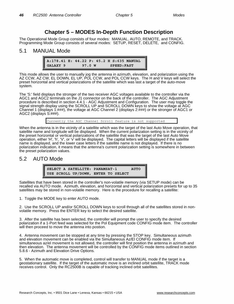
46 RC2500 Antenna Controller Chapter 5 Modes
Research Concepts, Inc. • 9501 Dice Lane • Lenexa, Kansas • 66215 • USA www.researchconcepts.com
Chapter 5 – MODES In-Depth Function Description The Operational Mode Group consists of four modes: MANUAL, AUTO, REMOTE, and TRACK. Programming Mode Group consists of several modes: SETUP, RESET, DELETE, and CONFIG.
5.1 MANUAL Mode
A:178.41 E: 44.22 P: 45.2 H S:635 MANUAL GALAXY 9 97.0 W SPEED:FAST
This mode allows the user to manually jog the antenna in azimuth, elevation, and polarization using the AZ CCW, AZ CW, EL DOWN, EL UP, POL CCW, and POL CCW keys. The H and V keys will select the preset horizontal and vertical polarizations of the satellite which was last a target of the auto-move system.
The 'S:' field displays the stronger of the two receiver AGC voltages available to the controller via the AGC1 and AGC2 terminals on the J1 connector on the back of the controller. The AGC Adjustment procedure is described in section 4.4.1 - AGC Adjustment and Configuration. The user may toggle the signal strength display using the SCROLL UP and SCROLL DOWN keys to show the voltage at AGC Channel 1 (displays 1:###), the voltage at AGC Channel 2 (displays 2:###) or the stronger of AGC1 or AGC2 (displays S:###).
Currently the AGC Channel Scroll feature is not supported
When the antenna is in the vicinity of a satellite which was the target of the last Auto Move operation, that satellite name and longitude will be displayed. When the current polarization setting is in the vicinity of the preset horizontal or vertical polarizations of the satellite that was the target of the last Auto Move operation, either 'H', 'h', 'V', or 'v' will be displayed. The capital letters will be displayed if the satellite name is displayed, and the lower case letters if the satellite name is not displayed. If there is no polarization indication, it means that the antenna's current polarization setting is somewhere in between the preset polarization values.
5.2 AUTO Mode
SELECT A SATELLITE: PANAMSAT-1 AUTO USE SCROLL UP/DOWN, ENTER TO SELECT
Satellites that have been stored in the controller's non-volatile memory (via SETUP mode) can be recalled via AUTO mode. Azimuth, elevation, and horizontal and vertical polarization presets for up to 35 satellites may be stored in non-volatile memory. Here is the procedure for recalling a satellite:
1. Toggle the MODE key to enter AUTO mode.
2. Use the SCROLL UP and/or SCROLL DOWN keys to scroll through all of the satellites stored in non-volatile memory. Press the ENTER key to select the desired satellite.
3. After the satellite has been selected, the controller will prompt the user to specify the desired polarization if a 1-Port feed was selected for the Pol Equipment code CONFIG mode item. The controller will then proceed to move the antenna into postion.
4. Antenna movement can be stopped at any time by pressing the STOP key. Simultaneous azimuth and elevation movement can be enabled via the Simultaneous Az/El CONFIG mode item. If simultaneous az/el movement is not allowed, the controller will first position the antenna in azimuth and then elevation. The antenna movement will be controlled by the CONFIG mode items outlined in section 5.8.6 - Azimuth and Elevation Drive Options.
5. When the automatic move is completed, control will transfer to MANUAL mode if the target is a geostationary satellite. If the target of the automatic move is an inclined orbit satellite, TRACK mode receives control. Only the RC2500B is capable of tracking inclined orbit satellites.
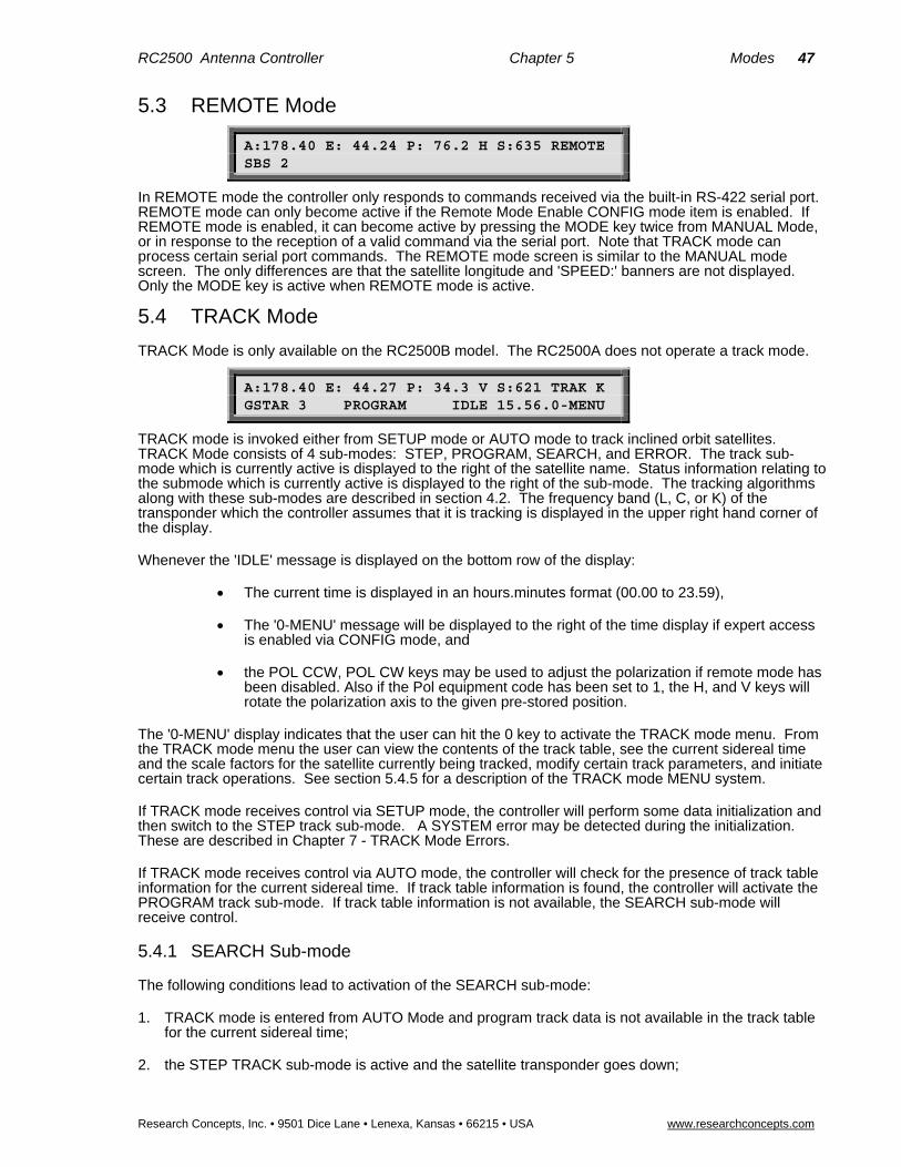
RC2500 Antenna Controller Chapter 5 Modes 47
Research Concepts, Inc. • 9501 Dice Lane • Lenexa, Kansas • 66215 • USA www.researchconcepts.com
5.3 REMOTE Mode
A:178.40 E: 44.24 P: 76.2 H S:635 REMOTE SBS 2
In REMOTE mode the controller only responds to commands received via the built-in RS-422 serial port. REMOTE mode can only become active if the Remote Mode Enable CONFIG mode item is enabled. If REMOTE mode is enabled, it can become active by pressing the MODE key twice from MANUAL Mode, or in response to the reception of a valid command via the serial port. Note that TRACK mode can process certain serial port commands. The REMOTE mode screen is similar to the MANUAL mode screen. The only differences are that the satellite longitude and 'SPEED:' banners are not displayed. Only the MODE key is active when REMOTE mode is active.
5.4 TRACK Mode
TRACK Mode is only available on the RC2500B model. The RC2500A does not operate a track mode.
A:178.40 E: 44.27 P: 34.3 V S:621 TRAK K GSTAR 3 PROGRAM IDLE 15.56.0-MENU
TRACK mode is invoked either from SETUP mode or AUTO mode to track inclined orbit satellites. TRACK Mode consists of 4 sub-modes: STEP, PROGRAM, SEARCH, and ERROR. The track sub-mode which is currently active is displayed to the right of the satellite name. Status information relating to the submode which is currently active is displayed to the right of the sub-mode. The tracking algorithms along with these sub-modes are described in section 4.2. The frequency band (L, C, or K) of the transponder which the controller assumes that it is tracking is displayed in the upper right hand corner of the display.
Whenever the 'IDLE' message is displayed on the bottom row of the display:
The current time is displayed in an hours.minutes format (00.00 to 23.59),
The '0-MENU' message will be displayed to the right of the time display if expert access is enabled via CONFIG mode, and
the POL CCW, POL CW keys may be used to adjust the polarization if remote mode has been disabled. Also if the Pol equipment code has been set to 1, the H, and V keys will rotate the polarization axis to the given pre-stored position.
The '0-MENU' display indicates that the user can hit the 0 key to activate the TRACK mode menu. From the TRACK mode menu the user can view the contents of the track table, see the current sidereal time and the scale factors for the satellite currently being tracked, modify certain track parameters, and initiate certain track operations. See section 5.4.5 for a description of the TRACK mode MENU system.
If TRACK mode receives control via SETUP mode, the controller will perform some data initialization and then switch to the STEP track sub-mode. A SYSTEM error may be detected during the initialization. These are described in Chapter 7 - TRACK Mode Errors.
If TRACK mode receives control via AUTO mode, the controller will check for the presence of track table information for the current sidereal time. If track table information is found, the controller will activate the PROGRAM track sub-mode. If track table information is not available, the SEARCH sub-mode will receive control.
5.4.1 SEARCH Sub-mode
The following conditions lead to activation of the SEARCH sub-mode:
1. TRACK mode is entered from AUTO Mode and program track data is not available in the track table for the current sidereal time;
2. the STEP TRACK sub-mode is active and the satellite transponder goes down;

48 RC2500 Antenna Controller Chapter 5 Modes
Research Concepts, Inc. • 9501 Dice Lane • Lenexa, Kansas • 66215 • USA www.researchconcepts.com
3. or PROGRAM TRACK mode is active, and the AGC inputs indicate that a satellite signal is not present when the sidereal time advances to a value for which track data is not available in the track table.
The behavior of the controller when the SEARCH sub-mode is active is determined by the state of the Search Enable CONFIG mode item. If Search is disabled, when the SEARCH sub-mode activates, the controller will prompt the user to manually align the antenna with the satellite (by using the jog keys) and hit the ENTER key to transfer control to the STEP TRACK sub-mode. If the sidereal time advances to a value for which track data is available in the track table, control will transfer to the PROGRAM TRACK sub-mode.
If the Search Enable CONFIG mode item is enabled, the controller will perform a search for the satellite using the Intelli-Search algorithm. When the search is performed, the controller will sweep the antenna in a serpentine shaped pattern over the region where it has calculated the satellite will be found. The width of the search box is controlled by the Search Width CONFIG mode item. If during the search a signal is detected above the appropriate AGC threshold (either C or K/L) the antenna will return to the position where the signal was detected and control will transfer to the STEP TRACK sub-mode. If the search is unsuccessful, the controller will wait for Search Retry minutes before initiating another search. The Search Retry parameter may be inspected and modified via the TRACK MENU - Modify menu. Additional information concerning the Search sub-mode is available in section 4.2.3. Note that for transmit applications it is generally advisable to disable the automatic search feature.
When the SEARCH sub-mode is active, the following messages will be displayed to the right of the satellite name on the bottom row of the display.
SEARCH - A search is in progress. If a satellite is found, the STEP track sub-mode activates.
SEARCH IDLE - A search has been performed and a satellite was not found. The controller is waiting to perform another search. The TRACK MENU function may be invoked to initiate another search, or to change the Search Retry Interval. If the sidereal time advances to a value for which track table data is available, the PROGRAM track sub-mode will activate.
5.4.2 STEP TRACK Sub-mode
When the STEP track sub-mode is active, the following actions can occur:
1. The antenna is periodically jogged in elevation and then in azimuth to peak-up the received signal strength.
2. The controller compiles the track table.
3. Control will transfer to the PROGRAM track sub-mode if the sidereal time advances to a value for which track table information is available.
4. If the signal strength indicates that the transponder has powered down, the controller will wait a short while for the transponder to come back online before activating the SEARCH sub-mode.
5. The TRACK MENU system may be used to immediately trigger a peaking operation. See section 5.4.5 for a description of the TRACK MENU system. A more detailed description of the STEP track algorithm is given in section 4.2.1.
When the STEP sub-mode is active, the following messages may be displayed:
STEP SIG OK IDLE - The AGC input indicates that a satellite signal is present and the controller is waiting to perform another peaking operation.
STEP SIG OK PEAKING - The controller is jogging the antenna to find the maximum signal strength. The step size is determined by the Max Track Error CONFIG Mode item, the antenna size, and the frequency band.
STEP NO SIG IDLE - The AGC input indicates that a satellite signal is not present (the AGC level is below the appropriate threshold level). The controller will wait approximately 5 minutes for the AGC to return before activating the SEARCH sub-mode.

RC2500 Antenna Controller Chapter 5 Modes 49
Research Concepts, Inc. • 9501 Dice Lane • Lenexa, Kansas • 66215 • USA www.researchconcepts.com
5.4.3 PROGRAM TRACK Sub-mode
In the PROGRAM track sub-mode, the controller positions the antenna based on values stored in the track table. The controller will also periodically perform a peaking operation similar to that which occurs in the STEP track sub-mode. If the difference between the peakup position and the position stored in the track table is greater than the error specified by the Max Track Error CONFIG mode item, the update flag for each track table entry is set. When a receiver AGC signal is present and the sidereal time is equal to that associated with a track table entry whose update flag is reset, a peakup occurs, the peakup azimuth and elevation position count values are placed in the track table, and the update flag for that track table entry is reset.
When the PROGRAM track sub-mode is active, control can switch to either the STEP track or SEARCH sub-modes when the sidereal time advances to a value for which track table data is not available. When this occurs, the STEP track sub-mode will activate if a receiver AGC signal is available, otherwise, control will transfer to the SEARCH sub-mode. A more detailed description of the PROGRAM track sub-mode may be found in section 4.2.2.
The TRACK MENU system may be used to immediately trigger a reposition of the antenna to the azimuth and elevation position derived from the track table, and to view the contents of the track table. The TRACK MENU system also allows the user to specify the time interval between peakup operations which check the accuracy of the data in the track table. Additionally, the TRACK MENU system allows the user to clear the track table. The menu system is described in section 5.4.5.
When the PROGRAM sub-mode is active the following messages may be displayed:
PROGRAM IDLE - The PROGRAM track sub-mode is active. The controller is waiting to reposition the antenna.
PROGRAM REPOSITION - The controller has determined that the antenna pointing error is greater than that specified by the max track error parameter, and is currently repositioning the antenna to a position derived from the track table.
PROGRAM PEAKING - The controller is performing a step track operation to either check the accuracy of or update a track table entry.
5.4.4 TRACK Mode - ERROR Sub-mode
The ERROR sub-mode activates whenever an error is detected. No tracking occurs while the ERROR submode is active. The only way to exit from the ERROR submode is to exit TRACK mode by hitting the MODE key, or via a Track Reset command received by the serial port. The various track mode errors are described in section 7.2 - TRACK MODE ERRORS.
5.4.5 TRACK MENU
The TRACK mode MENU system allows the user to view and modify data relating to the satellite being tracked. The MENU system may be invoked whenever the CONFIG mode Expert Access Flag is set by hitting the 0 key while in the SEARCH IDLE, STEP IDLE, and PROGRAM IDLE states. When the menu system is invoked, the user will be presented with the following display, referred to as the main MENU display.
1.VIEW 2.MODIFY 3.XXXXXX:_ MENU TRAK K SAT NAME ENTER TO EXIT
The contents of the field XXXXXX: will be either 'REPEAK', 'SEARCH', or 'ALIGN', depending on the track submode which is currently active. Note that track operations cease when the MENU system is active. Make sure that you always exit the MENU system. Hitting the ENTER key repeatedly will always cause the MENU system to terminate by returning control to the IDLE state.
VIEW
From the main MENU display, hit the 1 key to select the VIEW system. Here is the initial view display.

50 RC2500 Antenna Controller Chapter 5 Modes
Research Concepts, Inc. • 9501 Dice Lane • Lenexa, Kansas • 66215 • USA www.researchconcepts.com
TM,AZ,EL TTTTT AAAAA EEEEE MENU TRAK K SAT NAME SCROLL ^v,ENTER TO EXIT
Where
TTTTT is the sidereal time in seconds
AAAAA is the azimuth scale factor in position counts per radian
and EEEEE is the elevation scale factor in position counts per radian
Subsequent toggles on the SCROLL UP/DOWN keys display the following information from the track table.
II TTTTT AAAAA EEEEE F MENU TRAK K SAT NAME SCROLL ^v,ENTER TO EXIT
Where
II is the entry index, 0-47
TTTTT is the sidereal time in seconds for the entry
AAAAA is the azimuth position in counts
EEEEE is the elevation position in counts
and F denotes the state of the update flag. '.' indicates that the update flag is set, a blank indicates that the update flag is reset.
After the 47th entry has been displayed, the first screen will appear again and the entire process will repeat. To exit this option, press ENTER to return to the MENU screen.
MODIFY
From the main MENU display hit the 2 key to select the MODIFY system.
UPDATE CHECK 0-999 HRS: 72 MENU TRAK K SAT NAME SCROLL ^v,ENTER TO EXIT
There are 8 data items that the user is allowed to modify with this option. Each is successively accessed by pressing the SCROLL UP/DN keys and advancing through the list. Each entry is explained in Table 1.
TABLE 1
Entry Name Range Description
UPDATE CHECK 0-999 HRS The period of time between track table basepoint update checks. Default 33 hours.
SEARCH RETRY 0-999 MINS The period of time between successive SEARCH attempts when no signal is present and track table data is not available. Default 10 minutes.
BAND: C,K 1 or 2 For dual band inclined orbit satellites, this prompt allows the user to change the frequency band. Note that the current band is displayed in the upper right hand corner of the LCD.
CLEAR TRACK 0 or 1 Press 1 to clear the track table entries, or 0 to leave as is. Be careful with this one!

RC2500 Antenna Controller Chapter 5 Modes 51
Research Concepts, Inc. • 9501 Dice Lane • Lenexa, Kansas • 66215 • USA www.researchconcepts.com
RESET UPDATE 0 or 1 Press 1 to clear the track table UPDATE flags, 0 to not modify the existing data.
FORCE UPDATE 0 or 1 Press 1 to set the track table UPDATE flags, 0 to not modify the existing data. (Opposite function of RESET UPDATE.)
MAX ERROR 1-30 Specifies the maximum tracking error in tenths of a dB. Default value is 5.
SEARCH WIDTH 1-10 Specifies a normalized scaling factor that increases or decreases the width of the search window. Values greater than 3 increase it, less than 3 decrease it. Default value is 3.
To exit this option, press ENTER at any time to return to the MENU screen.
REPEAK, SEARCH, or ALIGN
Hitting the 3 key followed by the ENTER key at the main MENU display will initiate some action by the controller. The action taken depends on the TRACK sub-mode which is active. Table 2 describes the action taken for each of the track sub-modes.
TABLE 2
Sub-mode XXXXXX Action
STEP REPEAK Causes the controller to immediately repeak the antenna.
SEARCH SEARCH Causes the controller to initiate another search.
PROGRAM .ALIGN The controller will reposition the antenna based on the current sidereal time and the current az/el data in the track table.
Selecting item number 3 from the main MENU display will always cause the MENU system to terminate and initiate the selected action.
5.4.6 Continuous Step Tracking
Step Track Preference for Inclined Orbit Satellite
This feature forces the ACU to constantly remain in the Step Track sub-mode whenever signal strength is present. To enable this feature, the Update Check Interval must be set to zero.
To access the Update Check Interval:
1. Use the TRACK Mode “0-MENU” system. 2. Select “2.MODIFY” 3. Select “UPDATE CHECK 0-999 HRS:” 4. Enter a value of “0” (zero) and press enter.
The UPDATE CHECK setting determines how often the ACU updates the track table. When the number is set to zero, the ACU is forced to stay in Step Track mode, as long as signal strength is present. If signal strength is not present, the ACU will operate in Program Track (section 5.4.3) mode, as long as track table data is available. If signal strength is not present and track table data is not available, the ACU will operate in Automatic or Manual Search modes (section 5.4.1).
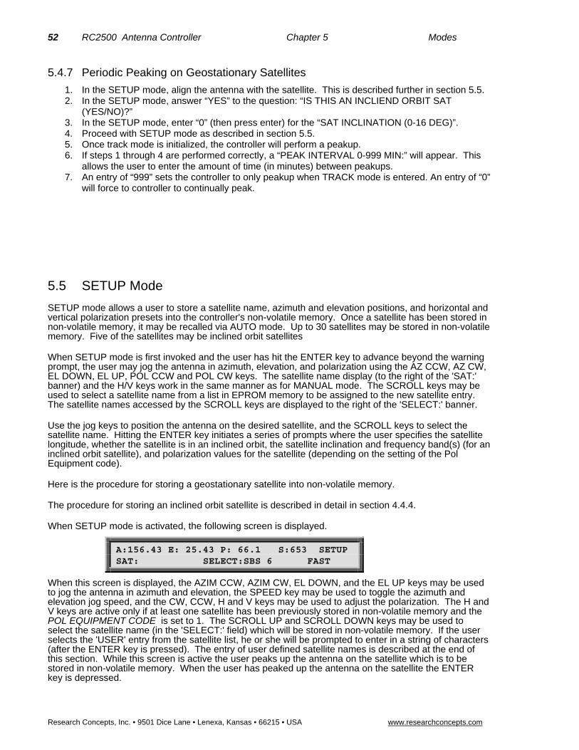
52 RC2500 Antenna Controller Chapter 5 Modes
Research Concepts, Inc. • 9501 Dice Lane • Lenexa, Kansas • 66215 • USA www.researchconcepts.com
5.4.7 Periodic Peaking on Geostationary Satellites
1. In the SETUP mode, align the antenna with the satellite. This is described further in section 5.5. 2. In the SETUP mode, answer “YES” to the question: “IS THIS AN INCLIEND ORBIT SAT
(YES/NO)?” 3. In the SETUP mode, enter “0” (then press enter) for the “SAT INCLINATION (0-16 DEG)”. 4. Proceed with SETUP mode as described in section 5.5. 5. Once track mode is initialized, the controller will perform a peakup. 6. If steps 1 through 4 are performed correctly, a “PEAK INTERVAL 0-999 MIN:” will appear. This
allows the user to enter the amount of time (in minutes) between peakups. 7. An entry of “999” sets the controller to only peakup when TRACK mode is entered. An entry of “0”
will force to controller to continually peak.
5.5 SETUP Mode
SETUP mode allows a user to store a satellite name, azimuth and elevation positions, and horizontal and vertical polarization presets into the controller's non-volatile memory. Once a satellite has been stored in non-volatile memory, it may be recalled via AUTO mode. Up to 30 satellites may be stored in non-volatile memory. Five of the satellites may be inclined orbit satellites
When SETUP mode is first invoked and the user has hit the ENTER key to advance beyond the warning prompt, the user may jog the antenna in azimuth, elevation, and polarization using the AZ CCW, AZ CW, EL DOWN, EL UP, POL CCW and POL CW keys. The satellite name display (to the right of the 'SAT:' banner) and the H/V keys work in the same manner as for MANUAL mode. The SCROLL keys may be used to select a satellite name from a list in EPROM memory to be assigned to the new satellite entry. The satellite names accessed by the SCROLL keys are displayed to the right of the 'SELECT:' banner.
Use the jog keys to position the antenna on the desired satellite, and the SCROLL keys to select the satellite name. Hitting the ENTER key initiates a series of prompts where the user specifies the satellite longitude, whether the satellite is in an inclined orbit, the satellite inclination and frequency band(s) (for an inclined orbit satellite), and polarization values for the satellite (depending on the setting of the Pol Equipment code).
Here is the procedure for storing a geostationary satellite into non-volatile memory.
The procedure for storing an inclined orbit satellite is described in detail in section 4.4.4.
When SETUP mode is activated, the following screen is displayed.
A:156.43 E: 25.43 P: 66.1 S:653 SETUP SAT: SELECT:SBS 6 FAST
When this screen is displayed, the AZIM CCW, AZIM CW, EL DOWN, and the EL UP keys may be used to jog the antenna in azimuth and elevation, the SPEED key may be used to toggle the azimuth and elevation jog speed, and the CW, CCW, H and V keys may be used to adjust the polarization. The H and V keys are active only if at least one satellite has been previously stored in non-volatile memory and the POL EQUIPMENT CODE is set to 1. The SCROLL UP and SCROLL DOWN keys may be used to select the satellite name (in the 'SELECT:' field) which will be stored in non-volatile memory. If the user selects the 'USER' entry from the satellite list, he or she will be prompted to enter in a string of characters (after the ENTER key is pressed). The entry of user defined satellite names is described at the end of this section. While this screen is active the user peaks up the antenna on the satellite which is to be stored in non-volatile memory. When the user has peaked up the antenna on the satellite the ENTER key is depressed.

RC2500 Antenna Controller Chapter 5 Modes 53
Research Concepts, Inc. • 9501 Dice Lane • Lenexa, Kansas • 66215 • USA www.researchconcepts.com
If the satellite name chosen is already stored in non-volatile memory, the user is presented with the following screen.
SELECT:SBS 6 DUPLICATE ENTRY SETUP OVERWRITE EXISTING DATA, USE YES/NO KEYS
If the user selects NO the initial screen is displayed and the selection process is repeated. The user is next prompted to specify whether or not the satellite is in an inclined orbit.
SELECT: SBS 6 SETUP IS THIS AN INCLINED ORBIT SAT (YES/NO)?
The user is next prompted to specify the satellite longitude with the following screen.
SELECT:SBS 6 SETUP ENTER SAT LON LLL.L: 99.0 W 0-9.ENT,BKSP
If the satellite name was not user defined, a value will be present in the longitude field. The longitude is specified in <degrees>.<tenths_of_degrees>.
If the satellite being set up is an inclined orbit satellite, the user will next be presented with the following prompt for the satellite band.
SELECT: SBS 6 SETUP SELECT BAND 0-C,1-K,2-C&K,3-L: ENT,BKSP
The response to this prompt will be either the 0, 1, 2, or 3 key.
For an inclined orbit satellite, the user will receive the following prompt for the satellite inclination.
SELECT: SBS 6 SETUP SAT INCLINATION (2-16): 5 ENT,BKSP
At this prompt, the user should enter the inclination angle of the satellite's orbital plane to the earth's equatorial plane. A default value of 5 degrees is offered.
For both geostationary and inclined orbit satellites, the user is next prompted to specify the horizontal and vertical polarizations if the POL EQUIPMENT CODE item is set to 1, or just a single polarization in the POL EQUIPMENT CODE item is set to 2. (The user is prompted to hit enter rather than H or V). If POL EQUIPMENT CODE is set to 0 the will be no prompt for polarizaiton.
SELECT:SBS 6 P: 75.6 SETUP USE CW, CCW TO ADJUST - H, V KEYS TO SET
When this screen is displayed the CW and CCW keys may be used to adjust the polarization, and the H and V keys may be used to set each polarization.
If the satellite being set up is in an inclined orbit, and both H and V polarizations were stored, the controller will prompt the user to specify the initial track polarization with the following message.
INITIAL TRACK POL (H OR V)?
At this point the user should select either H or V as the polarization to use for tracking when control switches to TRACK mode. When the user has selected the initial polarization, the 'DATA ACCEPTED' message will appear for a few seconds, and control will switch to TRACK mode.
If the satellite just entered was not an inclined orbit satellite, after the 'DATA ACCEPTED' message appears the controller remains in SETUP mode. Control transfers to the initial screen, and the process

54 RC2500 Antenna Controller Chapter 5 Modes
Research Concepts, Inc. • 9501 Dice Lane • Lenexa, Kansas • 66215 • USA www.researchconcepts.com
may be repeated. Note that the MODE key may be pressed at any time to exit the mode that is currently active.
User-Defined Satellite Names
If the desired satellite name is not in memory, you can assign a new name of up to ten (10) alphanumeric characters (A-Z, 0-9, hyphen (-), or space) by accessing the USER entry mode as follows.
From the screen which allows the user to jog the antenna in azimuth and elevation to peak up on the desired satellite, use the SCROLL UP/DOWN keys to bring up the 'USER' entry in the list, and press ENTER. The following screen will be displayed:
SELECT:* KEY IN SAT NAME SETUP USE SCROLL UP/DOWN, BKSP & ENTER KEYS
Note that the cursor will be displayed under the '*' character. The SCROLL UP and SCROLL DOWN keys may be used to select alpha-numeric characters (A-Z, 0-9, hyphen (-), and space). A space can be entered in the name by depressing SCROLL UP key once, and SCROLL DOWN key once, and then ENTER (from the ‘*’ prompt). The BKSP key may be used to delete the character to the left of the cursor. During alpha-numeric data entry, the ENTER key has two functions. If the ENTER key is depressed while the '*' character is displayed, the alpha-numeric data entry session is terminated. If the ENTER key is depressed when the '*' character is not displayed, the cursor will advance to the right one space and the user will be prompted again with the '*' character. If the ENTER key is depressed when the cursor is in the tenth character position of the satellite name data field the entry is terminated.
5.6 RESET Mode
The RESET mode is used to display azimuth, elevation, and polarization drive fault conditions, and to re-enable the drive outputs in the event the microcontroller has disabled an axis. When RESET mode is activated, one of the following screens will be displayed.
AZ: OK EL: OK RESET RESET AXIS: 1-AZ/EL
AZ: OK EL: OK PL: OK RESET RESET AXIS: 1-AZ/EL, 2-POL
The first screen will be displayed if POL EQUIPMENT CODE CONFIG mode item is set to 0, the second screen will be displayed if the POL EQUIPMENT CODE CONFIG mode item is set to 1 or 2.
The status of each axis is displayed after the appropriate banner (AZ:, EL:, or PL:) on the top line of the LCD. If a fault exists for an axis, no movement may occur about that axis until the fault condition for that axis is reset. Use the 1 key to reset the azimuth and elevation axes or the 2 key to reset polarization axis.
Here are the status messages which may be displayed:
OK
Indicates that no fault conditions are active for the axis (azimuth, elevation, or polarization).
JAMMED
Indicates that the antenna was commanded to move about the axis and no movement was detected by the controller. This indicates either that the antenna did not move when commanded to do so, or the sensor failed and the controller was not able to detect any movement (azimuth, elevation, or polarization).
RUNAWAY

RC2500 Antenna Controller Chapter 5 Modes 55
Research Concepts, Inc. • 9501 Dice Lane • Lenexa, Kansas • 66215 • USA www.researchconcepts.com
The drive was deactivated because the processor sensed movement for a drive which was not commanded to move. This error is rarely caused by an actual runaway condition (the antenna moving on its own). This error is usually due to a faulty sensor or noise pickup due to the sensor shield not being connected properly. See Chapter 3 for proper shield connection instructions (azimuth and elevation).
DRIVE
The axis was deactivated due to a drive fault condition (azimuth or elevation axis).
SENSOR
This error will occur if the antenna commands a polarization movement, and movement is detected in the wrong direction. Note that a polarization jammed condition will occasionally register as a sensor error. Polarization movement in the wrong direction should only occur during setup (polarization axis only).
5.7 DELETE Mode
SELECT A SATELLITE: PANAMSAT-1 DELETE USE SCROLL UP/DOWN, ENTER TO SELECT
This mode is used to delete a satellite entry. This mode can only be activated if the Expert Access flag is set. Refer to section 2.5 for more information on the expert access system.
To delete a satellite from the controller’s non-volatile memory:
1. Use the MODE key to activate DELETE mode.
2. Scroll through the ASSIGNED satellite names.
3. When the desired satellite name is shown, press ENTER. The system will display the message
DATA DELETED
5.8 CONFIG Mode The CONFIG mode allows the user to view and/or modify various controller parameters and to enable or disable certain features. When this mode is active, the SCROLL keys may be used to select various items for either viewing or modification. To change the value of a parameter, the user can simply key in a new value. The BKSP (backspace) KEY is active. If a new value is keyed in, for the change to take effect and update the parameter's value in the controller's non-volatile memory, the entry must be terminated with the ENTER key. If the present value of the parameter is invalid, '*' characters will be displayed in the item's data field. If the user terminates a data entry with the ENTER key and the value is accepted, the next CONFIG mode item will be displayed. If the user terminates a data entry with the ENTER key and the data is not accepted, the CONFIG mode item will not change. The MODE key can be pressed at any time to exit CONFIG mode.
Access to certain CONFIG mode items can be restricted depending on the status of the EXPERT ACCESS flag and by the values currently assigned to certain CONFIG mode items. When the EXPERT ACCESS flag is reset to “0” (see section 2.5), the only CONFIG mode items which will be accessible will be SIMULTANEOUS AZ/EL ENABLE, REMOTE MODE ENABLE, and EXPERT ACCESS ENABLE. When the EXPERT ACCESS flag is set to “1”, access to the other CONFIG mode items can be further restricted by the value of a controlling CONFIG mode item.
An example will clarify the concept of a controlling CONFIG mode item. Three CONFIG mode items related to access to the controller via its serial port are REMOTE MODE ENABLE, COMM PORT ADDRESS, and COMM BAUD RATE. The REMOTE MODE ENABLE CONFIG item is the controlling item for the COMM PORT ADDRESS and COMM BAUD RATE ITEMS. If the REMOTE MODE ENABLE CONFIG mode item has a value of 0 (disabled) then the other two items will not appear in the list of CONFIG mode items. In the descriptions which follow the controlling items and the items which are controlled by other items will be clearly delineated.
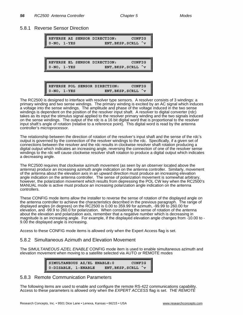
56 RC2500 Antenna Controller Chapter 5 Modes
Research Concepts, Inc. • 9501 Dice Lane • Lenexa, Kansas • 66215 • USA www.researchconcepts.com
5.8.1 Reverse Sensor Direction
REVERSE AZ SENSOR DIRECTION: CONFIG 0-NO, 1-YES ENT,BKSP,SCRLL ^v
REVERSE EL SENSOR DIRECTION: CONFIG 0-NO, 1-YES ENT,BKSP,SCRLL ^v
REVERSE POL SENSOR DIRECTION: CONFIG 0-NO, 1-YES ENT,BKSP,SCRLL ^v
The RC2500 is designed to interface with resolver type sensors. A resolver consists of 3 windings: a primary winding and two sense windings. The primary winding is excited by an AC signal which induces a voltage into the sense windings. The amplitude and phase of the voltage induced in the two sense windings is dependent on the position of the resolver input shaft. A resolver to digital converter (rdc) takes as its input the stimulus signal applied to the resolver primary winding and the two signals induced on the sense windings. The output of the rdc is a 16 bit digital word that is proportional to the resolver input shaft’s angle of rotation (relative to a reference point). This digital word is read by the antenna controller’s microprocessor.
The relationship between the direction of rotation of the resolver’s input shaft and the sense of the rdc’s output is governed by the connection of the resolver windings to the rdc. Specifically, if a given set of connections between the resolver and the rdc results in clockwise resolver shaft rotation producing a digital output which indicates an increasing angle, reversing the connection of one of the resolver sense windings to the rdc will cause clockwise resolver shaft rotation to produce a digital output which indicates a decreasing angle.
The RC2500 requires that clockwise azimuth movement (as seen by an observer located above the antenna) produce an increasing azimuth angle indication on the antenna controller. Similarly, movement of the antenna about the elevation axis in an upward direction must produce an increasing elevation angle indication on the antenna controller. The sense of polarization movement is somewhat arbitrary, however, the polarization movement which results from depressing the POL CW key when the RC2500’s MANUAL mode is active must produce an increasing polarization angle indication on the antenna controllers.
These CONFIG mode items allow the installer to reverse the sense of rotation of the displayed angle on the antenna controller to achieve the characteristics described in the previous paragraph. The range of displayed angles (in degrees) on the RC2500 is 0.00 to 359.99 for azimuth, -99.99 to 260.00 for elevation, and -99.9 to 260.0 for polarization. When considering the sense of rotation of the antenna about the elevation and polarization axis, remember that a negative number which is decreasing in magnitude is an increasing angle. For example, if the displayed elevation angle changes from -10.00 to -9.00 the displayed angle is increasing.
Access to these CONFIG mode items is allowed only when the Expert Access flag is set.
5.8.2 Simultaneous Azimuth and Elevation Movement
The SIMULTANEOUS AZ/EL ENABLE CONFIG mode item is used to enable simultaneous azimuth and elevation movement when moving to a satellite selected via AUTO or REMOTE modes
SIMULTANEOUS AZ/EL ENABLE:0 CONFIG 0-DISABLE, 1-ENABLE ENT,BKSP,SCRLL ^v
5.8.3 Remote Communication Parameters
The following items are used to enable and configure the remote RS-422 communications capability. Access to these parameters is allowed only when the EXPERT ACCESS flag is set. THE REMOTE

RC2500 Antenna Controller Chapter 5 Modes 57
Research Concepts, Inc. • 9501 Dice Lane • Lenexa, Kansas • 66215 • USA www.researchconcepts.com
MODE ENABLE item is the controlling item for the COMM PORT ADDRESS and COMM BAUD RATE items.
The REMOTE MODE ENABLE item is used to enable access to REMOTE mode. If REMOTE mode is enabled, the controller will respond to serial commands whose address matches the controller's address. If the controller is not in TRACK mode and a valid command is received, control will transfer to REMOTE mode. If TRACK mode is active and a valid command is received, TRACK mode will process the command (without interrupting the track) if the command does not specify azimuth or elevation movement. If the command does specify movement, control will transfer to REMOTE mode and tracking will cease. See the Appendices for the command set.
REMOTE MODE ENABLE:0 CONFIG 0-DISABLE, 1-ENABLE ENT,BKSP,SCRLL ^v
The COMM PORT ADDRESS item selects the address of the communications port. Valid values for this parameter are 49 to 111.
COMM PORT ADDRESS: 50 CONFIG 49 - 111 ENT,BKSP,SCRLL ^v
The COMM BAUD RATE item selects the baud rate that the controller’s serial port will be initialized to. Valid values for this parameter are 3 (300 baud), 6 (600 baud), 12 (1200 baud), 24 (2400 baud), 48 (4800 baud) and 96 (9600 baud).
COMM BAUD RATE (HUNDREDS):96 CONFIG 3, 6, 12, 24, 48, 96 ENT,BKSP,SCRLL ^v
5.8.4 Position Display Offsets
AZIM DISPLAY OFFSET: 45.5 CONFIG -179.99 TO 180.00 ENT,BKSP,SCRLL ^v
ELEV DISPLAY OFFSET: -13.5 CONFIG -179.99 TO 180.00 ENT,BKSP,SCRLL ^v
POL DISPLAY OFFSET: 2.5 CONFIG -179.99 TO 180.00 ENT,BKSP,SCRLL ^v
The values specified for the AZIM DISPLAY OFFSET, ELEV DISPLAY OFFSET, and POL DISPLAY OFFSET CONFIG mode items are added to the position values sensed by the azimuth, elevation, and polarization position sensors, respectively. These CONFIG mode items can be used to convert the antenna’s sensed positions into actual pointing angle.
Note that the resolvers must be installed such that the sensed position does not wrap around (from 0.00 to 360.00 or 360.00 to 0.00) within the antenna’s normal range of movement for a given installation. The controller’s Azim Display Offset, Elev Display Offset, and Pol Display Offset CONFIG mode items can be used to correct for any position offsets introduced by this requirement.
5.8.5 Polarization Display Scale Factor
POL DISPLAY SCALE FACTOR:50 CONFIG DEG/VOLT, 5-100 ENT,BKSP,SCRLL ^v
RC2500s that use a potentiometer (POL-POT option) for the polarization position should set the scale factor for angle readout. The scale factor is specified as the amount of degrees per volt. The scale factor
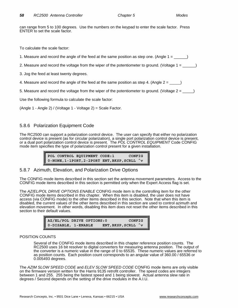
58 RC2500 Antenna Controller Chapter 5 Modes
Research Concepts, Inc. • 9501 Dice Lane • Lenexa, Kansas • 66215 • USA www.researchconcepts.com
can range from 5 to 100 degrees. Use the numbers on the keypad to enter the scale factor. Press ENTER to set the scale factor.
To calculate the scale factor:
1. Measure and record the angle of the feed at the same position as step one. (Angle 1 = ______)
2. Measure and record the voltage from the wiper of the potentiometer to ground. (Voltage 1 = ______)
3. Jog the feed at least twenty degrees.
4. Measure and record the angle of the feed at the same position as step 4. (Angle 2 = _____)
5. Measure and record the voltage from the wiper of the potentiometer to ground. (Voltage 2 = _____)
Use the following formula to calculate the scale factor:
(Angle 1 - Angle 2) / (Voltage 1 - Voltage 2) = Scale Factor.
5.8.6 Polarization Equipment Code
The RC2500 can support a polarization control device. The user can specify that either no polarization control device is present (as for circular polarization), a single port polarization control device is present, or a dual port polarization control device is present. The POL CONTROL EQUIPMENT Code CONFIG mode item specifies the type of polarization control present for a given installation.
POL CONTROL EQUIPMENT CODE:1 CONFIG 0-NONE,1-1PORT,2-2PORT ENT,BKSP,SCRLL ^v
5.8.7 Azimuth, Elevation, and Polarization Drive Options
The CONFIG mode items described in this section set the antenna movement parameters. Access to the CONFIG mode items described in this section is permitted only when the Expert Access flag is set.
The AZ/EL/POL DRIVE OPTIONS ENABLE CONFIG mode item is the controlling item for the other CONFIG mode items described in this chapter. When this item is disabled, the user does not have access (via CONFIG mode) to the other items described in this section. Note that when this item is disabled, the current values of the other items described in this section are used to control azimuth and elevation movement. In other words, disabling this item does not reset the other items described in this section to their default values.
AZ/EL/POL DRIVE OPTIONS:0 CONFIG 0-DISABLE, 1-ENABLE ENT,BKSP,SCRLL ^v
POSITION COUNTS
Several of the CONFIG mode items described in this chapter reference position counts. The RC2500 uses 16 bit resolver to digital converters for measuring antenna position. The output of the converter is a numeric value in the range of 0 to 65535. These numeric values are referred to as position counts. Each position count corresponds to an angular value of 360.00 / 65536 or 0.005493 degrees.
The AZIM SLOW SPEED CODE and ELEV SLOW SPEED CODE CONFIG mode items are only visible on the firmware version written for the Harris 9135 retrofit controller. The speed codes are integers between 1 and 255. 255 being the fastest speed and 1 being slowest. Actual antenna slew rate in degrees / Second depends on the setting of the drive modules in the A.I.U.

RC2500 Antenna Controller Chapter 5 Modes 59
Research Concepts, Inc. • 9501 Dice Lane • Lenexa, Kansas • 66215 • USA www.researchconcepts.com
AZIM SLOW SPEED CODE:176 CONFIG 1 –255 ENT,BKSP,SCRLL ^v
During an automatic move, when the antenna position is within AZ/EL FAST/SLOW THRESHOLD position counts of the target position, the antenna speed will switch from fast to slow.
AZ/EL FAST SLOW THRESHOLD: 400 CONFIG 0-1000 COUNTS ENT,BKSP,SCRLL ^v
The AZ/EL AUTO RETRY ATTEMPTS CONFIG mode item sets the maximum number of attempts which will be made to hit a target position (within MAX POSITION ERROR COUNTS - described below) during an automatic move initiated from AUTO or TRACK modes.
AZ/EL AUTO RETRY ATTEMPTS:3 CONFIG 2-5 ENT,BKSP,SCRLL ^v
The 'FAST DEADBAND and 'SLOW DEADBAND CONFIG mode items are used for the anti-reversal system. The anti-reversal system keeps the antenna from rapidly changing direction. If the antenna has been moving in a given direction, the Deadband CONFIG mode items specify the amount of time that the system will wait before asserting the antenna drive lines to move the antenna in the opposite direction. There are 2 different Deadband values specified - there are unique fast and slow speed values. If the antenna has been moving fast, the Fast Deadband parameters specify the wait interval; if the antenna has been moving slow, the Slow Deadband parameters specify the wait interval. Both Deadband values are given in milliseconds.
AZ/EL FAST DEADBAND:2000 CONFIG 175-5000 MSEC ENT,BKSP,SCRLL ^v
AZ/EL SLOW DEADBAND: 800 CONFIG 175-5000 MSEC ENT,BKSP,SCRLL ^v
During an automatic move in AUTO or TRACK modes, the 'COAST THRESHOLD CONFIG mode items set the number of counts before the target position is reached where the drive will be deactivated. The idea is to deactivate the drive and let the antenna coast into position. If, prior to the initiation of the move operation, the total number of counts that the actuator has to move to reach the target position is less than the COAST THRESHOLD, the drive will be deactivated when its position is within MAX POSITION ERROR counts of the target position.
AZIM COAST THRESHOLD: 40 CONFIG 1-500 COUNTS ENT,BKSP,SCRLL ^v
ELEV COAST THRESHOLD: 40 CONFIG 1-500 COUNTS ENT,BKSP,SCRLL ^v
The MAX POSITION ERROR CONFIG mode items set the maximum acceptable error between the final resting position and a target position for an automatic move which occurs in AUTO mode.
AZIM MAX POSITION ERROR: 5 CONFIG 0-100 COUNTS ENT,BKSP,SCRLL ^v
ELEV MAX POSITION ERROR: 5 CONFIG 0-100 COUNTS ENT,BKSP,SCRLL ^v

60 RC2500 Antenna Controller Chapter 5 Modes
Research Concepts, Inc. • 9501 Dice Lane • Lenexa, Kansas • 66215 • USA www.researchconcepts.com
A similar set of quantities are defined for the polarization axis.
POL FAST SLOW THRESHOLD: 80 CONFIG 0-1000 COUNTS ENT,BKSP,SCRLL ^v
POL AUTO RETRY ATTEMPTS:3 CONFIG 2-5 ENT,BKSP,SCRLL ^v
POL FAST DEADBAND:2000 CONFIG 175-5000 MSEC ENT,BKSP,SCRLL ^v
POL SLOW DEADBAND: 800 CONFIG 175-5000 MSEC ENT,BKSP,SCRLL ^v
POL COAST THRESHOLD: 40 CONFIG 1-500 COUNTS ENT,BKSP,SCRLL ^v
POL MAX POSITION ERROR: 5 CONFIG 0-100 COUNTS ENT,BKSP,SCRLL ^v
5.8.8 Time and Date Settings
Access to the Time and Date CONFIG mode items is permitted only when the EXPERT ACCESS flag is set. Time and Date are only used in track modes, therefore this section may be ignored for the RC2500A controller.
ENTER TIME (HH.MM.SS): 08.46.00 CONFIG USE 0-9 OR . ENT,BKSP,SCRLL ^v
The real-time clock must be set to establish a time reference for all tracking data stored in the controller. Enter the local time using the 0-9 keys and the . key to separate the hours, minutes, and seconds fields. Each field must have two digits entered; i.e., 8 must be entered as 08 or the unit will not accept the entry. The time cannot be changed for daylight-savings time purposes once valid track data is stored, or the unit will not function properly.
ENTER DATE (MM.DD.YY):07.03.92 CONFIG USE 0-9 OR . ENT,BKSP,SCRLL ^v
Enter the current date in the format shown. Again, use the 0-9 keys to enter the month, day, and year fields, and use the . key to separate fields. Single digit fields must be entered with a 0 preceding, as shown in the example for 07.03.92.
Note: The RC2500 is Y2K compliant. The sidereal time is derived from the real-time clock as the number of seconds that have elapsed since 00:00 on 1 January 1992.
5.8.9 Signal Strength Parameters
The controller has to have signal strength information for tracking inclined orbit satellites. Signal strength information is generally obtained from the receiver's automatic gain control (AGC) system. The

RC2500 Antenna Controller Chapter 5 Modes 61
Research Concepts, Inc. • 9501 Dice Lane • Lenexa, Kansas • 66215 • USA www.researchconcepts.com
procedures used to adjust the controller's AGC input circuits and obtain these parameters is described in section 4.4.1 - AGC Adjustment and Configuration. Access to these CONFIG mode items is permitted only when the EXPERT ACCESS FLAG is set. The AGC port signal-strength is displayed in MANUAL mode but it is only used during track modes, therefore this section may be ignored for the RC2500A controller.
AGC POLARITY FLAG;1 CONFIG 0-NEGATIVE 1-POSITIVE ENT,BKSP,SCRLL ^v
The AGC Polarity Flag tells the controller what the sense is on the input AGC voltage used for tracking. A positive sense is defined as one that increases in magnitude as the RF signal strength increases. If the AGC voltage decreases as the RF signal increases, its sense is considered negative. Enter the appropriate value, either 0 or 1, followed by ENTER to key in the value.
AGC C BAND THRESHOLD:125 CONFIG 0 - 999 ENT,BKSP,SCRLL ^v
When the receiver is tuned to a C band satellite and the signal strength is above the AGC C Band Threshold value, it is assumed that a satellite signal is present. The same threshold is applied to both AGC channels.
AGC K/L BAND THRESHOLD:150 CONFIG 0 - 999 ENT,BKSP,SCRLL ^v
This is similar to the C band threshold described above, except it pertains to Ku or L band. If the signal strength is above the AGC K/L Band Threshold value when the receiver is tuned to a Ku or L band satellite, the controller assumes that a satellite signal is present.
5.8.10 Antenna Parameters
The following items specify antenna related parameters which are used by the tracking system. Access to these items is only permitted when the EXPERT ACCESS flag is set. These parameters are used only in the track modes, therefore this section may be ignored for the RC2500A controller.
ANTENNA LATITUDE LL.L: 38.9 N CONFIG TENTHS AFTER DEC. PT ENT,BKSP,SCRLL ^v
ANTENNA LONGITUDE LLL.L: 97.5 W CONFIG TENTHS AFTER DEC. PT ENT,BKSP,SCRLL ^v
The antenna location is necessary for the satellite track path prediction algorithm. The format for these entries is <degrees>.<tenths of degrees> (as opposed to a <degrees>.<minutes> format found on most maps). A conversion table from minutes to tenths of degrees is shown below.
Minutes Tenths of Degrees Minutes Tenths of Degrees 00 .0 30 .5 06 .1 36 .6 12 .2 42 .7 18 .3 48 .8 24 .4 54 .9
After entering the latitude/longitude using the 0-9 and “.” keys, press ENTER. The RC2500B will prompt for the appropriate direction terminator, E/W for longitude, N/S for latitude. Enter the correct value using the 2-North, 8-South, 4-East, or 6-West keys. Terminate the entry with the ENTER key.
ANT SIZE (40 - 1200):244 CONFIG CENTIMETERS ENT,BKSP,SCRLL ^v
The Antenna Size is used to calculate various parameters associated with TRACK mode. The size is specified in centimeters, and the following table lists some common sizes.

62 RC2500 Antenna Controller Chapter 5 Modes
Research Concepts, Inc. • 9501 Dice Lane • Lenexa, Kansas • 66215 • USA www.researchconcepts.com
Diam. in Feet Diam. In Meters RC2000C Input 5.9 1.8 180 8.0 2.44 244 10.0 3.05 305 12.0 3.66 366 15.0 4.57 457 20.0 6.1 610 23.0 7.0 700
Use the 0-9 keys followed by ENTER to input the antenna diameter
5.8.11 Track Mode Parameters
The following parameters are used by the track system. These parameters are described in more detail in chapter 4. These items may only be accessed when the EXPERT ACCESS flag is set. These parameters are used only in the track modes, therefore this section may be ignored for the RC2500A controller.
5.8.11.1 MAX TRACK ERROR
MAX TRACK ERROR(1-30):5 CONFIG IN TENTHS OF A DB ENT,BKSP,SCRLL ^v
The MAX TRACK ERROR CONFIG mode item specifies the maximum antenna tracking error in tenths of a dB. This parameter has more influence over the operation of the tracking system than any other. The significance of this variable is described in detail in sections 4.2.1 and 4.2.2 of this manual, which cover the operation of the controller in the STEP TRACK and PROGRAM TRACK sub-modes.
In the STEP TRACK sub-mode, the value of this parameter determines how often peaking operations occur. The controller will peak the antenna often enough so that in between peakups the signal strength variation due to antenna pointing error will not exceed Max Track Error tenths of a dB.
In the PROGRAM TRACK sub-mode, the controller tracks that satellite based on the current sidereal time, and data in the track table. The controller will reposition the antenna often enough so that the error between the antenna's azimuth and elevation position and the azimuth and elevation positions derived from interpolation of track table data is less than Max Track Error tenths of a dB.
The MAX TRACK ERROR parameter specifies the azimuth and elevation step sizes during peaking operations which occur during the STEP TRACK and PROGRAM TRACK sub-modes. Some users erroneously conclude that the smallest value of Max Track Error leads to the tightest track. When the value of this parameter is reduced to a point where the peakup azimuth or elevation step sizes approach the value of the mechanical hysteresis (slop) of the antenna – sensor interconnect, the controller cannot peakup properly. This can lead to PEAK LIMIT errors, or to the antenna peaking itself off of the satellite.
Here is the mechanism which can lead to this undesirable result:
1. The Max Track Error parameter is set to a 'low' value which results in an elevation peakup step size of just one position count.
2. When a peakup occurs, the controller measures the signal strength at the current antenna position, and then moves the antenna up or down in elevation in an attempt to find the strongest satellite signal. After recording the signal strength at the starting position, the controller moves the antenna up in elevation by one position count.
3. Due to mechanical hysteresis, the antenna's pointing angle does not change even though the antenna's elevation resolver has moved one position count.
4. Thermal noise in the receiver's AGC circuit or changing atmospheric conditions result in the controller measuring a stronger AGC input at the 'new' antenna position.
5. Since a stronger signal was measured when the antenna moved up, the controller concludes that the satellite has moved up. The controller will record the signal strength at the current antenna position, and again move up by one position count. At the new position, the controller will measure the signal strength again to determine if the signal is stronger at the new position than at the starting position.

RC2500 Antenna Controller Chapter 5 Modes 63
Research Concepts, Inc. • 9501 Dice Lane • Lenexa, Kansas • 66215 • USA www.researchconcepts.com
This process will continue until a weaker signal strength is recorded. When that occurs, the controller will back up one step and conclude that it has found the elevation peak.
6. A problem occurs if the controller makes the wrong decision at step 4. Any time the controller step size is comparable in magnitude to the antenna's mechanical hysteresis, a problem WILL eventually occur.
For most antennas the MAX TRACK ERROR should not be made smaller than 5 (0.5 dB). The fundamental ability of an antenna system to track a satellite will depend to a large extent on the mechanical characteristics of the mount.
5.8.11.2 SEARCH ENABLE
SEARCH ENABLE:1 CONFIG 0-DISABLE, 1-ENABLE ENT,BKSP,SCRLL ^v
The SEARCH ENABLE CONFIG mode item specifies whether or not the Intelli-Search algorithm is enabled or disabled. When the STEP TRACK submode is active and the signal strength input indicates that the satellite transponder has gone down, the controller will switch to the SEARCH sub-mode. The SEARCH ENABLE CONFIG mode item is the controlling item for the SEARCH WIDTH CONFIG mode item which is described next.
If the SEARCH ENABLE CONFIG mode item is enabled, the controller will execute the Intelli-Search algorithm. During an Intelli-Search, the controller will perform a serpentine-shaped search over a region where the controller has calculated that the satellite's apparent motion will take it. If the satellite is not found during the Intelli-Search, the search is periodically repeated until either signal strength information is available, or track table information becomes available.
If the SEARCH ENABLE item is disabled, the user is simply prompted to manually position the antenna on the satellite and hit the ENTER key to continue. The Intelli-Search should be disabled for transmit applications. It may also be advantageous to disable Intelli-Search for antennas which move very slowly.
5.8.11.3 SEARCH WIDTH
SEARCH WIDTH:3 CONFIG 1-10, NOMINAL=3 ENT,BKSP,SCRLL ^v
The SEARCH WIDTH item controls the width of the sweeps that occur during execution of the Intelli-Search algorithm. If the angular extent of the sweeps is too large, the controller could mistakenly align the antenna with an adjacent satellite. A search with narrow sweeps takes much less time to complete, but may not sweep over a region which is wide enough to find the satellite.
The SEARCH WIDTH is not an absolute value - increasing its value results in wider sweeps, and decreasing its value narrows the sweeps. The actual pointing angle over which search sweeps occur is a function of the antenna beamwidth and the SEARCH WIDTH parameter. For a given SEARCH WIDTH value, the search sweeps of an antenna with a narrower beamwidth will be greater than for an antenna with a larger beamwidth.
The default SEARCH WIDTH value of 3 is appropriate for satellites with 2-degree spacing. For faster searches, the value can be lowered to 1 or 2.
Access to the SEARCH WIDTH CONFIG mode item is only allowed when the SEARCH ENABLE CONFIG mode item described above is set to 1 (enabled).
5.8.12 Expert Access Flag
EXPERT ACCESS is used to control access to CONFIG mode items. When the EXPERT ACCESS flag is set (ON or 1), the user has access to all controller modes and all CONFIG mode items. When the EXPERT ACCESS Flag is reset (OFF), the user is locked out of several modes and most CONFIG mode items. The purpose of this feature is to keep an operator away from the modes and CONFIG mode items which can change the contents of the controller's non-volatile memory.

64 RC2500 Antenna Controller Chapter 5 Modes
Research Concepts, Inc. • 9501 Dice Lane • Lenexa, Kansas • 66215 • USA www.researchconcepts.com
When the EXPERT ACCESS screen is displayed, the present state of the EXPERT ACCESS Flag is displayed in the data entry field. A display value of 1 indicates that the EXPERT ACCESS Flag is set, and a value of 0 indicates that the flag is reset. To toggle the state of the flag, the user must key in a 5 digit code at the prompt followed by the ENTER key. This code is found in Appendix A, a removable page. If the information is lost, call the factory for assistance.
EXPERT ACCESS (0-OFF, 1-ON): 1 CONFIG ENTER CODE TO TOGGLE ENT,BKSP,SCRLL ^v
5.8.13 Reset System Data
The RESET SYSTEM DATA CONFIG mode data item is used to reset the controller's non-volatile memory. When this occurs, and most of the various CONFIG mode items are initialized to a default value. In addition, all previously stored satellites are deleted. This operation is performed at the factory prior to shipment. Access to this item is allowed only when the EXPERT ACCESS flag is set. To reset the system memory, the user must key in the same 5 digit code used for Expert Access, followed by the ENTER key. This code is found in Appendix A, a removable page. If the information is lost, call the factory for assistance.
RESET SYSTEM DATA: 0 CONFIG ENTER CODE ENT,BKSP,SCRLL ^
When field upgrading to firmware versions that operate with a memory map different from the current version a system reset will be necessary. Appendix A contains the procedure for field upgrades of the firmware.

RC2500 Antenna Controller Chapter 6 Specifications 65
Research Concepts, Inc. • 9501 Dice Lane • Lenexa, Kansas • 66215 • USA www.researchconcepts.com
Chapter 6 – Specifications Inspect unit for any damage caused during shipping. If any exists, notify shipper immediately. During the Installation process be sure to record all of the applicable CONFIG mode data and stored satellite position for later reference.
A. PHYSICAL
Size: 19.0" x 3.5"H x 9.0"D (Rack)
Weight: 7 lbs.
Temperature: 0-50oC
Input Power: 115/230 VAC, 50/60 Hz., 48 W, single-pole fused ½ Amp.
B. TRACK MODE
Antenna Size: 0.4 - 12.0 meters
Tracking Accuracy: Mount/Resolver Dependent
0.1 - 3.0 dB, selectable
Maximum Inclination: +/- 16 deg., standard
Tracking Modes: Intelli-Searchtm, Step Track, Program Track
AGC Input Range: -15 volts to 15 volts DC
AGC Input Impedance: 2M ohm
AGC Inputs: 2
Inclined Satellites: 5 Max
Total Number of Satellites: 30 (Geo + Inclined Orbit).
C. Non-Volatile Memory Battery - Duracell DL2450

66 RC2500 Antenna Controller Chapter 7 Troubleshooting/Alarm Codes
Research Concepts, Inc. • 9501 Dice Lane • Lenexa, Kansas • 66215 • USA www.researchconcepts.com
Chapter 7 – TROUBLESHOOTING/ALARM CODES The alarm system monitors important system parameters and flashes a message on the bottom line of the LCD display if an error is found. The parameters monitored include the condition of the lithium battery, status of the azimuth and elevation antenna drive systems, and the values of certain variables. Some error codes have priority over others. Alarm conditions are sampled sequentially, with the highest priority sampled first. As corrective action is taken for each error, the code is eliminated, and if there is a lesser error, it will then appear.
7.1 SYSTEM ERROR CODES The alarm system monitors important system parameters and flashes a message on the bottom line of the LCD display if an error is found. The parameters monitored include the condition of the lithium battery, status of the azimuth and elevation antenna drive systems, and the values of certain variables. Some error codes have priority over others. Alarm conditions are sampled sequentially, with the highest priority sampled first. As corrective action is taken for each error, the code is eliminated, and if there is a lesser error, it will then appear.
Many of the alarm messages described in this section are caused by corrupt CONFIG mode items. Note that access to certain CONFIG mode items is controlled by the value of other CONFIG mode items. See the first few paragraphs of section 5.8 for an explanation of the role of controlling CONFIG mode items. If the value of a controlling CONFIG mode item is such that access to other CONFIG mode items is restricted, corrupt values of those other CONFIG mode items can still generate an alarm message. Access to the corrupted item is only available if the controlling item is changed to allow it.
All of the CONFIG mode items must be initialized to a valid value, even if the feature associated with that CONFIG mode item is disabled. For example, even if REMOTE mode is disabled, the Comm Port Baud Rate and Comm Port Address CONFIG mode items must still be initialized properly.
LOW BATTERY
The RC2000C constantly monitors the level of the lithium battery. When the power level is low, this error code will appear. Replace the battery with a Duracell DL2450. Make sure that the unit is unplugged from the AC power before removing the cover to change the battery. Take care to hold the battery tab away from the battery housing while replacing the battery, and it will not be necessary to reprogram the memory. Since there is a chance that the non-volatile memory will be corrupted when the battery is changed, please refer to the Appendix A section entitled ‘Updating RC2500 Antenna Controllers that are In-Service’ before changing the battery.
ESTOP
This alarm message indicate that the Emergency Stop button at the A.I.U. has been actuated. Determine the cause of the emergency stop. No antenna motion is allowed from the RC2500 or the A.I.U. when this alarm is active. This error may be reset only by resetting the Emergency Stop button located near the Antenna in the A.I.U. ESTOP is controlled by a current loop described in Sec. 3.3.2. Interruption of this current loop by a broken connection or loop supply failure will also produce the error. Refer to the controller specific appendices for details about this error in non-standard applications.
MAINTENANCE
This alarm message indicate that the Remote/Maintenance switch at the A.I.U. has set to allow local jogging of the antenna from the A.I.U. In this state, the RC2500 cannot control antenna motion and simply displays the position of each axis. This Status Flag may be reset only by switching the Remote/Maintenance switch at the A.I.U. to Remote. MAINTENANCE is controlled by a current loop described in Sec. 3.3.2. Interruption of this current loop by a broken connection or loop supply failure will also produce the error. Refer to the controller specific appendices for details about this error in non-standard applications.
SUMMARY LIMIT
For the ‘7134 Summary Limits’ firmware version, the arrival of the antenna at any of the six position limits will produce a Summary Limit alarm. The Summary Limit alarm message indicates that a limit has been reached on one of the antenna axes. Antenna motion in this state is limited only by the limit switch
RC2500 Antenna Controller Chapter 7 Error Codes 67
Research Concepts, Inc. • 9501 Dice Lane • Lenexa, Kansas • 66215 • USA www.researchconcepts.com
position at the A.I.U. This error may be reset only by moving the antenna away from the limit of the offending axis. In the event that a limit is reached and the move key for that axis is held down for an extended period, a jam error will occur. The jam will not be evident due to the higher priority of the summary limit alarm. If this occurs, first reset the jammed error then, move the antenna away from the limit. See Section 5.6. SUMMARY LIMIT is controlled by a current loop described in Sec. 3.3.2. Interruption of this current loop by a broken connection or loop supply failure will also produce the error. Refer to the controller specific appendices for details about this error in non-standard applications.
UP, DOWN, CW, CCW limits
For the ‘7134 Individual Limits’ firmware version, the arrival of the antenna at any of the six position limits (AZ- CW/CCW, EL UP/DOWN, and POL- CW/CCW) will produce a Limit Display over the angular readout for that axis. Antenna motion for the given axis and direction is not allowed. To clear the limit and begin displaying the angular position, move the antenna away from the limit with the keypad in manual mode. All axis limits are controlled by a current loops described in Sec. 3.3.2. Interruption of these current loops by a broken connection or loop supply failure will also produce Limit displays. Refer to the controller specific appendices for details about these errors in non-standard applications.
ANT AZIM, ANT ELEV, ANT POL
These alarm messages indicate that an error has been detected for the axis referenced in the alarm message. When one of these alarms are detected, the axis is disabled. Go to RESET mode (section 5.6) to view the actual fault condition which was detected and to clear the fault.
AZIM SLOW SPEED, ELEV SLOW SPEED
The azimuth and elevation slow speed codes have been corrupted. The slow speed codes are entered via the Azim and Elev Slow Speed CONFIG mode items. See Sections 5.8.6 and 3.4.3
COMM PORT
This error (caused by an incorrect checksum) indicates that the value of at least one of the following CONFIG mode items has been corrupted: Remote Mode Enable, Comm Port Baud Rate, or Comm Port Address. Remote Mode Enable is the controlling item for this group of CONFIG mode items - it must be enabled to allow access to the Comm Port Baud Rate and Comm Port Address CONFIG mode items. See section 5.8.3.
POL OPTIONS
This error (caused by an incorrect checksum) indicates that the value of at least one of the following CONFIG mode items has been corrupted: Polarization Equipment Code. See sections 5.8.5 and 3.4.1.
AZ/EL OPTIONS
This error (caused by an incorrect checksum) indicates that the value of at least one of the following CONFIG mode items has been corrupted: Az/El/Pol Drive Options Enable, Az/El Fast Slow Threshold, Az/El Retry Attempts, Az/El Fast Deadband, Az/El Slow Deadband, Azim Coast Threshold, Elev Max Position Error, or Simultaneous Az/El Enable. The Az/El Drive Options Enable CONFIG mode item is the controlling item for most members of this group of CONFIG mode items - it must be enabled to allow access to the other items. See sections 5.8.6 and 3.4.
TIME/DATE
This alarm code indicates either the Time or Date is corrupt. The time and date are entered via CONFIG mode. See section 5.8.7.
ANT/RCVR CONFIG
This error codes indicates that at least one of the following CONFIG mode items is corrupt: AGC Polarity Flag, AGC C Band Threshold, AGC K/L Band Threshold, Antenna Latitude, Antenna Longitude, Ant Size, Azim Constant, or Elev Constant. See sections 5.8.8 and 5.8.9.

68 RC2500 Antenna Controller Chapter 7 Troubleshooting/Alarm Codes
Research Concepts, Inc. • 9501 Dice Lane • Lenexa, Kansas • 66215 • USA www.researchconcepts.com
TRACK CONFIG
This error code indicates that at least one of the following CONFIG mode items is corrupt: Max Track Error, Search Enable, or Search Width. See section 5.8.10.
7.2 TRACK MODE ERRORS
Should one of the following errors occur during TRACK operation, the controller will display an error message mid-position of the second row on the display. All tracking operations will halt until the error is corrected.
JAMMED
If the controller does not sense feedback/position changes from the resolver-to-digital converter while it asserts the drive lines, it will halt the drive signals and display the JAMMED message. To reset the error use the mode key to enter RESET mode and reset the axis that was shut down. See Section 5.6.
LIMIT
The controller encountered an azimuth or elevation limit during a track movement operation. This represents a serious error because it means the limits have to be changed to allow tracking of this satellite. When installing the antenna, be sure to set the limits wide enough to allow ample tracking over the entire range.
RUNAWAY
This error indicates a runaway or large, unexpected position change. The controller will shut down the drive experiencing this error and will have to be reset in RESET mode. Section 5.6
DRIVE
This error indicates a drive system fault due to over-current or drive failure. The controller will shut down the drive experiencing this error and will have to be reset in RESET mode. Section 5.6
PEAK LIMIT
This error indicates that the antenna moved too far in either azimuth or elevation while attempting to peak the antenna. This error is described in section 4.4.6 - Tracking Problems.
SYSTEM
System errors were summarized in section 7.1.
CHECKSUM
This error indicates the memory in the satellite's track table or header has been corrupted. The only way to correct this error is to re-initialize the satellite by re-storing it in SETUP mode. See Section 5.5.
7.3 OPERATIONAL TROUBLESHOOTING TIPS
ANTENNA MUST BE PEAKED MANUALLY AFTER AN AUTO-MOVE
The Controller returns to approximately the correct position but must be re-peaked manually to achieve a good signal. This is generally an indication of mechanical hysteresis (slop) between the antenna pointing position and the position sensor. When this occurs the antenna will peak up in one position when approaching the satellite from the west and another when approaching the satellite from the east. To test for this, move the antenna quite a distance west of the satellite and manually move the antenna east at slow speed until the peak is reached. Repeat the procedure when approaching the satellite from the east. The difference in azimuth position between the 2 peaks is the mechanical hysteresis. In this

RC2500 Antenna Controller Chapter 7 Error Codes 69
Research Concepts, Inc. • 9501 Dice Lane • Lenexa, Kansas • 66215 • USA www.researchconcepts.com
situation, try to eliminate the slop in the mount. If this is not possible, always approach each satellite from the same direction in which it was originally programmed (typically east to west).
ANT AZIM, ANT ELEV or ANT POL ERRORS OCCUR
To determine the cause of this error, go to RESET mode. One of the following error messages will be displayed: JAMMED, RUNAWAY, or DRIVE. Here are the likely causes of each of these errors:
JAMMED - This error indicates that the drive was commanded to move, but movement was not sensed. This can be caused by an mechanical jam at the antenna, or the antenna may be moving but position feedback changes are not getting back to the controller. Determine which condition exists.
If the antenna is not moving there may either be a faulty motor, a wiring problem, or a mechanical limit switch has been encountered and is not registering at the controller. If the antenna is moving but position changes are not reaching the controller, check the resolver wiring and the physical mounting of the resolver on the antenna mount.
RUNAWAY - This error occurs when are large, unexpected position change is encountered when the antenna has not been commanded to move. If the Antenna has not actually moved, check the resolver wiring for intermittent connections.
DRIVE - This error indicates that the motor drive modules located in the A.I.U. have encountered a fault condition. This fault condition may be due to a temporary over-current or an actual drive failure. The failure may be reset in RESET mode. If the problem persists, check the documentation received with the A.I.U. for possible causes of the drive fault. See Section 5.6.
ENTRY SELECTED HOLDS INVALID DATA
When a satellite is selected via auto mode, the controller displays the message “ENTRY SELECTED HOLDS INVALID DATA”. Before the controller executes an automatic move it checks to see if the azimuth, elevation, and polarization (if any) data items are valid. If they are not, the error message is displayed. This error can also occur if the state of the POL CONTROL EQUIPMENT CODE CONFIG mode item was changed after the satellite was programmed into non-volatile memory.
GAPS IN THE TRACK TABLE
If the program track table has gaps even though the transponder has not powered down, there may no be a problem and just a slight change in a CONFIG mode item may be in order. In TRACK sub-mode, the controller periodically peaks the antenna. Two events can trigger a peaking operation. The antenna will peakup at the sidereal times corresponding to entries in the track table, and store the peak azimuth and elevation antenna positions. A peaking operation will also occur whenever the controller calculates that the antenna pointing error could exceed the error specified by the Max Track Error CONFIG mode item because of the satellite's apparent motion. The controller calculates this time interval by knowing the satellite's inclination, and calculating the antenna beamwidth based on the antenna size and frequency band.
Since the track table has 48 entries and a sidereal day is 23 hours, 56 minutes and 4 seconds long, a track table-inspired peakup will occur roughly every 30 minutes. A problem can arise if a Max Track Error inspired peakup is in progress when the track table peakup should occur - the controller will not perform the track table peakup, and no azimuth and elevation position data will be stored in the track table. This causes gaps in the track table data (which may be examined via the TRACK MENU - VIEW function). To prevent this from occurring, the controller will not initiate a Max Track Error peakup within 120 seconds prior to a sidereal time which corresponds to a track table entry. The 120 seconds is referred to as the Peakup Holdoff Interval.
The user can change the Peakup Holdoff Interval by manipulating the value of the Az/El Slow Deadband CONFIG mode item. If the Az/El Slow Deadband CONFIG mode item is a multiple of 50, the default value of 120 seconds is used as the Peakup Holdoff Interval. The user can select any Peakup Holdoff Interval (up to 500 seconds) by selecting a Peakup Holdoff Interval which is not a multiple of 50.
The relationship between these two items is illustrated by way of an example:
Az/El Slow Deadband = 818 milliseconds

70 RC2500 Antenna Controller Chapter 7 Troubleshooting/Alarm Codes
Research Concepts, Inc. • 9501 Dice Lane • Lenexa, Kansas • 66215 • USA www.researchconcepts.com
818 divided by 50 equals 16 with a remainder of 18. For this case the Peakup Holdoff Interval will be (18 * 10) or 180 seconds.
The Peakup Holdoff Interval should be longer than the worst case time that it takes to perform a peaking operation. The worst case peakup time will correspond to the portion of the satellite's apparent motion when the satellite is passing through the earth's equatorial plane.

RC2500 Antenna Controller Appendix A Expert Access/ Reset Code 71
Research Concepts, Inc. • 9501 Dice Lane • Lenexa, Kansas • 66215 • USA www.researchconcepts.com
Appendix A – EXPERT ACCESS / RESET SYSTEM DATA CODE To clear the system memory or toggle the expert access, the user must enter the five-digit code 41758, then press enter. This code has been printed in this removable appendix only, so that management can choose to remove the information to eliminate the possibility of inexperienced users entering the code and clearing the memory inadvertently. USE CAUTION!
For a discussion of expert access, see section 5.8.11. RESET SYSTEM DATA is covered in section 5.8.12
72 RC2500 Antenna Controller Appendix B Field Upgrading
Research Concepts, Inc. • 9501 Dice Lane • Lenexa, Kansas • 66215 • USA www.researchconcepts.com
Appendix B – Field Upgrading
Updating RC2500 Antenna Controllers that are In-Service. This paper explains the procedure for upgrading the firmware for RC2500 series Antenna Controllers. The controller firmware is contained in an EPROM memory chip. Changing the EPROM may sometimes corrupt the data stored in the non-volatile memory of the controller. This procedure ensures that this data is valid after the upgrade. Following the firmware upgrade procedure, the system reset and operating voltage change procedures are listed.
1. Enter into CONFIG mode and verify that Expert Access is enabled. (See manual section 5.8.11 for enabling instructions) Verify that REMOTE MODE is enabled. (See manual section 5.8.3 for enabling instructions) Scroll through the list with the SCROLL UP and SCROLL DWN keys. Log every item on the included worksheet.
2. Using AUTO mode, position the antenna on each of the geostationary satellites stored in memory. Record the name, longitude, and azimuth/ elevation positions for each on the bottom half of the Config mode items worksheet. While positioned on each satellite, use the H and V keys to move to horizontal and vertical polarization (if applicable). Record these values on the worksheet.
3. Turn the unit off and disconnect it from the remaining components of the antenna system. Move the unit to a static-free workstation for chip replacement. Remove the lid and position the unit on the bench facing toward you.
4. Locate the RC2500 digital board (B-2_5KDIG1) located on the right side of the unit. Remove the existing EPROM chip (U4) from its socket and replace it with the upgrade EPROM.
5. Make sure proper grounding straps are used to avoid static discharge damage to the processor section. Make sure the chip is oriented properly in its socket. The notch or dot should line up with the notch of the outline silk-screened onto the PCB under the socket. Make sure that the legs of the EPROM package fit into each pin socket and do not bend up under the IC upon insertion.
6. Verify that U4 is properly oriented in its socket. Replace the lid, reinstall the 2500 into the rack, and reconnect the other components of the antenna system.
7. Power-up the RC2500 and verify the start-up banner and subsequent manual mode.
8. Go to CONFIG mode and key-in the data recorded in Step 2. Each entry must be terminated with the ENTER key. After the data has been entered, scroll through the CONFIG mode items and verify correct data entry.
9. Go to SETUP mode. Position the antenna on each of the satellites that were recorded in step 2. Select the satellite name, enter the satellite longitude, and move the polarization axis to the recorded H and V positions in response to the appropriate SETUP mode prompts. See Sec. 5.5 for SETUP mode details.
10. Using AUTO mode, position the antenna on each of the geostationary satellites stored in memory. Verify that the antenna moves to each satellite correctly. This completes the procedure.
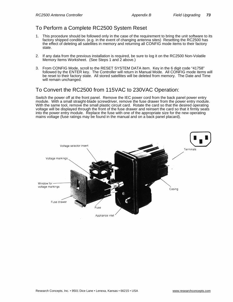
RC2500 Antenna Controller Appendix B Field Upgrading 73
Research Concepts, Inc. • 9501 Dice Lane • Lenexa, Kansas • 66215 • USA www.researchconcepts.com
To Perform a Complete RC2500 System Reset
1. This procedure should be followed only in the case of the requirement to bring the unit software to its factory shipped condition. (e.g. in the event of changing antenna sites) Resetting the RC2500 has the effect of deleting all satellites in memory and returning all CONFIG mode items to their factory state.
2. If any data from the previous installation is required, be sure to log it on the RC2500 Non-Volatile Memory Items Worksheet. (See Steps 1 and 2 above.)
3. From CONFIG Mode, scroll to the RESET SYSTEM DATA item. Key in the 6 digit code “41758” followed by the ENTER key. The Controller will return in Manual Mode. All CONFIG mode items will be reset to their factory state. All stored satellites will be deleted from memory. The Date and Time will remain unchanged.
To Convert the RC2500 from 115VAC to 230VAC Operation: Switch the power off at the front panel. Remove the IEC power cord from the back panel power entry module. With a small straight-blade screwdriver, remove the fuse drawer from the power entry module. With the same tool, remove the small plastic circuit card. Rotate the card so that the desired operating voltage will be displayed through the front of the fuse drawer and reinsert the card so that it firmly seats into the power entry module. Replace the fuse with one of the appropriate size for the new operating mains voltage (fuse ratings may be found in the manual and on a back panel placard).

74 RC2500 Antenna Controller Appendix B Field Upgrading
Research Concepts, Inc. • 9501 Dice Lane • Lenexa, Kansas • 66215 • USA www.researchconcepts.com
RC2500 Non-Volatile Memory Items Worksheet 1 Current Firmware Version ___________________
CONFIG MODE ITEMS
REVERSE AZ SENS DIRECTION: ____________ REVERSE EL SENS DIRECTION: ____________ REVERSE POL SENS DIRECTION: ___________ AZIM SLOW SPEED CODE: _________________ ELEV SLOW SPEED CODE: ________________ SIMULTANEOUS AZ/EL ENABLE: ____________ REMOTE MODE ENABLE: __________________ COMM PORT ADDRESS: ___________________ COMM BAUD RATE: _______________________ AZIM DISPLAY OFFSET: ___________________ ELEV DISPLAY OFFSET: ___________________ POL DISPLAY OFFSET: ____________________ POL CONTROL EQUIPMENT CODE: _________ AZ/EL/POL DRIVE OPTIONS: _______________ AZ/EL FAST SLOW THRESHOLD: ____________ AZ/EL AUTO RETRY ATTEMPTS: ____________ AZ/EL FAST DEADBAND: __________________ AZ/EL SLOW DEADBAND: __________________ AZIM COAST THRESHOLD: ________________ ELEV COAST THRESHOLD: ________________ AZIM MAX POSITION ERROR: ______________
ELEV MAX POSITION ERROR: ______________ POL FAST SLOW THRESHOLD: _____________ POL AUTO RETRY ATTEMPTS: _____________ POL FAST DEADBAND: ____________________ POL SLOW DEADBAND: ___________________ POL COAST THRESHOLD: _________________ POL MAX POSITION ERROR: _______________ CURRENT TIME (HH.MM.SS): _______________ CURRENTE DATE (MM.DD.YY): _____________ AGC POLARITY FLAG: ____________________ AGC C BAND THRESHOLD: ________________ AGC K/L BAND THRESHOLD: _______________ ANTENNA LATITUDE: _____________________ ANTENNA LONGITUDE: ___________________ ANT SIZE: _______________________________ MAX TRACK ERROR: _____________________ SEARCH ENABLE: ________________________ SEARCH WIDTH: _________________________ EXPERT ACCESS: special code to toggle enable_ RESET SYSTEM DATA: special code for RESET_
Satellite positions stored in memory
Name LONG AZ EL POl
________ _____ ______ ______ _______
________ _____ ______ ______ _______
________ _____ ______ ______ _______
________ _____ ______ ______ _______
________ _____ ______ ______ _______
________ _____ ______ ______ _______
________ _____ ______ ______ _______
________ _____ ______ ______ _______
________ _____ ______ ______ _______
________ _____ ______ ______ _______
________ _____ ______ ______ _______
________ _____ ______ ______ _______
________ _____ ______ ______ _______
________ _____ ______ ______ _______
________ _____ ______ ______ _______

RC2500 Antenna Controller Appendix B Field Upgrading 75
Research Concepts, Inc. • 9501 Dice Lane • Lenexa, Kansas • 66215 • USA www.researchconcepts.com
RC2500 Non-Volatile Memory Items Worksheet 2 Current Firmware Version ___________________
CONFIG MODE ITEMS
REVERSE AZ SENS DIRECTION: ____________ REVERSE EL SENS DIRECTION: ____________ REVERSE POL SENS DIRECTION: ___________ AZIM SLOW SPEED CODE: _________________ ELEV SLOW SPEED CODE: _________________ SIMULTANEOUS AZ/EL ENABLE: ____________ REMOTE MODE ENABLE: __________________ COMM PORT ADDRESS: ___________________ COMM BAUD RATE: _______________________ AZIM DISPLAY OFFSET: ___________________ ELEV DISPLAY OFFSET: ___________________ POL DISPLAY OFFSET: ____________________ POL CONTROL EQUIPMENT CODE:__________ AZ/EL/POL DRIVE OPTIONS: ________________ AZ/EL FAST SLOW THRESHOLD: ____________ AZ/EL AUTO RETRY ATTEMPTS: ____________ AZ/EL FAST DEADBAND: ___________________ AZ/EL SLOW DEADBAND: __________________ AZIM COAST THRESHOLD: _________________ ELEV COAST THRESHOLD: ________________ AZIM MAX POSITION ERROR: _______________
ELEV MAX POSITION ERROR: ______________ POL FAST SLOW THRESHOLD: _____________ POL AUTO RETRY ATTEMPTS: _____________ POL FAST DEADBAND: ____________________ POL SLOW DEADBAND: ___________________ POL COAST THRESHOLD: _________________ POL MAX POSITION ERROR: _______________ CURRENT TIME (HH.MM.SS): _______________ CURRENTE DATE (MM.DD.YY): _____________ AGC POLARITY FLAG: _____________________ AGC C BAND THRESHOLD: ________________ AGC K/L BAND THRESHOLD: _______________ ANTENNA LATITUDE: _____________________ ANTENNA LONGITUDE: ___________________ ANT SIZE: _______________________________ MAX TRACK ERROR: ______________________ SEARCH ENABLE: ________________________ SEARCH WIDTH: _________________________ EXPERT ACCESS: special code to toggle enable_ RESET SYSTEM DATA: special code for RESET_
Satellite positions stored in memory
Name LONG AZ EL POl
________ _____ ______ ______ _______
________ _____ ______ ______ _______
________ _____ ______ ______ _______
________ _____ ______ ______ _______
________ _____ ______ ______ _______
________ _____ ______ ______ _______
________ _____ ______ ______ _______
________ _____ ______ ______ _______
________ _____ ______ ______ _______
________ _____ ______ ______ _______
________ _____ ______ ______ _______
________ _____ ______ ______ _______
________ _____ ______ ______ _______
________ _____ ______ ______ _______
________ _____ ______ ______ _______
Name LONG AZ EL POl
________ _____ ______ ______ _______
________ _____ ______ ______ _______
________ _____ ______ ______ _______
________ _____ ______ ______ _______
________ _____ ______ ______ _______
________ _____ ______ ______ _______
________ _____ ______ ______ _______
________ _____ ______ ______ _______
________ _____ ______ ______ _______
________ _____ ______ ______ _______
________ _____ ______ ______ _______
________ _____ ______ ______ _______
________ _____ ______ ______ _______
________ _____ ______ ______ _______
________ _____ ______ ______ _______

76 RC2500 Antenna Controller Appendix C RS-422 Serial Interface
Research Concepts, Inc. • 9501 Dice Lane • Lenexa, Kansas • 66215 • USA www.researchconcepts.com
Appendix C – RS-422 Serial Interface The RC1000A, RC2000A, RC2000C, and RC2500 antenna controllers support an RS-422 serial interface. The communications protocol employed by RCI is compatible with the SABUS standard originally developed by the Scientific Atlanta Corporation. The protocol is described in appendix D - RS-422 Communications Protocol. The aspects of the communications interface which are unique to the RC2500 antenna controller are described in Appendix E RC2500-RS-4-22 Command Set.
RS-232 to RS-422 Protocol Converter The RS-422 signal levels are not directly compatible with the RS-232 serial ports available on personal computers. RS-232 is a point to point protocol - a PC can only communicate with one peripheral connected to the PC via an RS-232 interface. The RS-422 interface employed by the RC2000 allows a single PC to communicate with up 63 devices. An RS-232 to RS-422 protocol converter (designated RC1KADP) is available from Research Concepts, Inc. The diagrams and schematics at the end of this appendix document the connection of a PC to an RC2500 via an RC1KADP protocol converter.
Software Software to control the RC2500 is available from a number of sources. The diskette included with the manual includes a program which allow a PC to control an RC2500 (a protocol converter is required). The RC2500_A.EXE program is designed primarily for use by software developers or by integrators during installation. This program features a crude user interface which displays each byte of data sent to the controller and each byte received from the controller in an ASCII format and hex format. We recommend that this program be used to verify the operation of the system during initial installation and checkout of the RC1KADP and the associated cabling.
The Autopilot 2/16 and 4/16 software packages are produced by Broadcast Automation Systems ( (905) 822-7935) and are available from Research Concepts. This program can control theRC2500, RC2000 and the RC1000A antenna controllers as well as the Standard Agile Omni model 830BR or the DX657 satellite receivers. This program runs under Windows 95 and NT and gives the user the ability to schedule antenna and receiver events. Contact Research Concepts For more information on these products.
Here are other suppliers of software products which are compatible with the RC1000/RC2000/RC2500.
Crystal Computer Corporation, (404) 263-0555
Florical Systems, (904) 372-8326
Image Communications, (408) 335-2141
Louth Automation, (415) 329-9498
Link Research (UK) ++44 1923 244 233
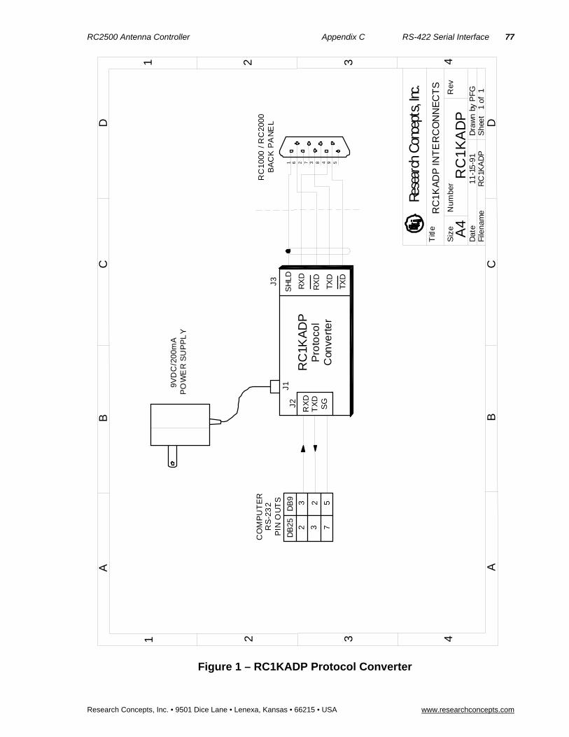
RC2500 Antenna Controller Appendix C RS-422 Serial Interface 77
Research Concepts, Inc. • 9501 Dice Lane • Lenexa, Kansas • 66215 • USA www.researchconcepts.com
Figure 1 – RC1KADP Protocol Converter
DB
9D
B25
3 2 5
2 3 7
CO
MP
UT
ER
RS
-23
2P
IN O
UT
S
9V
DC
/20
0mA
PO
WE
R S
UP
PL
Y
RC
1KA
DP
INT
ER
CO
NN
EC
TS
11-1
5-9
1R
C1K
AD
P
RX
DT
XD
SG
TX
D
TX
D
RX
D
SH
LDJ2
J3
J1
RC
1KA
DP
Pro
toco
lC
onve
rte
r
RC
1K
AD
P
594837261
RC
10
00 /
RC
200
0B
AC
K P
AN
EL
A4
Nu
mb
erR
ev
Titl
e
Siz
e
She
et
1 o
f 1
Dra
wn
by P
FG
File
nam
eD
ate
A A
B B
C C
D D
11
22
33
44
Rese
arch
Con
cept
s, In
c.
RX
D

78 RC2500 Antenna Controller Appendix D The RCI RS422 Interface Specification
Research Concepts, Inc. • 9501 Dice Lane • Lenexa, Kansas • 66215 • USA www.researchconcepts.com
Appendix D – The RCI RS422 Interface Specification
Introduction The purpose of this document is to explain the key parameters needed by a user to interface to the RCI RS422 Interface. This interface is compatible with the SAbus and can be readily integrated into an existing SAbus network. A few query and control commands are all that are needed to control the equipment and fetch all data from it. The user should refer to RCI document ‘RC2500 Communications Protocol’ for the specific program commands and descriptions of their functions.
Electrical Specifications RS-422 is a unipolar, balanced, 5-volt serial interface designed to connect equipment which must exchange data over considerable distances with high-noise immunity and high speed. Standard IC drivers and receivers are available for RS-422 that convert to and from TTL logic levels. The RS-422 drivers/receivers in the controllers allow up to 32 devices to be connected in parallel with up to 1,500 feet between the master and group of controllers.
Physical Specifications The physical implementation of the interface takes the form of a 9-pin "D" connector located on the rear panel of the controller. This connector and its wiring is compatible with EIA RS-449, which is the mechanical specification for RS-422/423-compatible equipment. The 9-pin connector chosen is described as the secondary interface in RS-449 and has only the four data lines and shield. No hardware handshaking is used in the protocol, so all the control lines specified for the standard 37-pin connector are not needed. The controller operates as a slave only and has a female connector, whereas master devices have male connectors. Multiple controllers, connected in a daisy chain fashion, can operate in electrical parallel with only a single 5-conductor cable required to connect all devices controlled by a master. Figure 1 illustrates the connection of a master and multiple controllers.
RS-422 Protocol
The interface is a multi-drop, balanced line, asynchronous, full-duplex communications link designed to interconnect equipment for remote control and switching applications. Products that are compatible can be linked together over a parallel-connected 4-wire circuit without regard to their particular function.
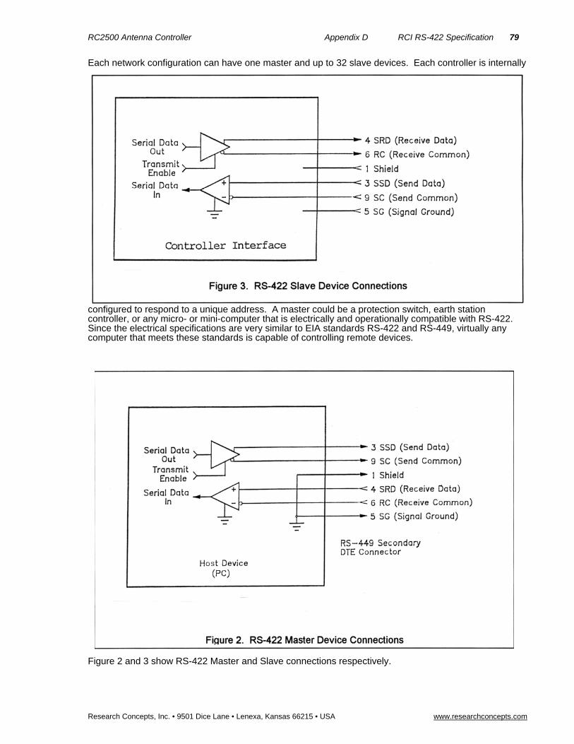
RC2500 Antenna Controller Appendix D RCI RS-422 Specification 79
Research Concepts, Inc. • 9501 Dice Lane • Lenexa, Kansas 66215 • USA www.researchconcepts.com
Each network configuration can have one master and up to 32 slave devices. Each controller is internally
configured to respond to a unique address. A master could be a protection switch, earth station controller, or any micro- or mini-computer that is electrically and operationally compatible with RS-422. Since the electrical specifications are very similar to EIA standards RS-422 and RS-449, virtually any computer that meets these standards is capable of controlling remote devices.
Figure 2 and 3 show RS-422 Master and Slave connections respectively.

80 RC2500 Antenna Controller Appendix D The RCI RS422 Interface Specification
Research Concepts, Inc. • 9501 Dice Lane • Lenexa, Kansas • 66215 • USA www.researchconcepts.com
Data Format
The data format supports the industry's standard asynchronous ASCII format with one start bit, eight data bits (7-bit ASCII with the 8th bit sent as even parity), and one stop bit. The ASCII control character subset 00-1F (hex) are reserved for message control. The printable ASCII characters 20-7F (hex) are used for address, command and data characters. The standard bus data rate via direct connect (up to 1,500 ft.) is 9,600 BAUD; the data rate for devices connected to a master via modem is 1,200 BAUD, typically.
Message Protocol Message format and protocol over the bus is a derivative of IBM's binary synchronous communications protocol (BISYNC). The master station sends a command over the bus to all remote stations. The station whose address is contained in the second byte of the command message carries out the requested commands, and then replies with a response message containing its own address and status information relating to its present condition. A remote station only sends a response following a command containing its unique address from the master. This prevents bus contention caused by more than one remote device communicating over the bus at the same time.
A remote device ignores all commands that contain parity or checksum errors, protocol errors, a wrong address, or message overrun errors. A remote device replies with a not-acknowledged (NAK) character, 15 hex, if it receives an invalid command or data.
Message Format Command messages (see Figure 4) begin with Start-of-text byte, STX, followed by a remote address, a command byte and multiple data bytes. The End-of-text byte, ETX, is sent following the last data byte, and the message is terminated by a checksum character. Response messages are identical to command messages in format (but not content) with the exception of the ACK (Acknowledge) or NAK (Not Acknowledge) character at the start of the message instead of STX. Figure 4 illustrates the format of the command and response messages. A command or reply message may have a variable length.
Message Delimiters
A command message begins with STX (02 hex), the ASCII Start-of-text control character. A message-acknowledged reply begins with ACK (06 hex), the ASCII Acknowledge control character, and a message-not acknowledged reply begins with NAK (15 hex), the ASCII Not Acknowledge control character. All messages end with the ETX (03 hex), the ASCII End-of-text control character, followed by the checksum byte.

RC2500 Antenna Controller Appendix D RCI RS-422 Specification 81
Research Concepts, Inc. • 9501 Dice Lane • Lenexa, Kansas 66215 • USA www.researchconcepts.com
Address Character The device address must be a valid ASCII printable character between 31 and 6F in hex; thus, 63 addresses are possible. These are set in the controller in decimal format, or 49-111.
Command Character
The command character (CMD) immediately follows the device address and specifies one of several possible commands for a particular device. See RCI document ‘RC2500 Command Set’ for a complete description of these commands.
Check Character
The last character of any message is the check character (CHK). This character is simply the bit-by-bit exclusive OR of all characters in the message starting with the STX character through the ETX character. This forms a Longitudinal Redundancy parity check over the entire message.
Message Timing
The NAK or ACK reply does not signify that a function has actually taken place, but only that the message was received and understood. The user should query the controller later to see if the command was actually carried out, or is still in progress. Figure 5 shows the controller state diagram.
Command Restrictions All slaves will respond to a command "0", 30 (hex), with 6 data bytes of ASCII characters in the following form:
ACK ADDR 30 type D5 D6 ETX CHSUM
where type is RC2K for an RC2000A, RC1K for an RC1000A, 2KCA for an RC2000C for el-over-az mounts, 2KCP for an RC2000C for polar mounts, 2KCE for az-over-el mounts, 2500 for the RC2500A, 25CA for an RC2500B for el-over-az mounts, 25CP for an RC2500B for polar mounts, and 25CE for az-over-el mounts.
Slave State Diagram: Introduction General Description. The slave State diagram (see Figure 5) presents the required protocol implementation at the slave device that guarantees the proper transfer and processing of communication messages sent by a Master controller.
State Diagram Notation. Each state that a slave can assume is represented graphically as a circle. A single-digit number is used within the circle to identify the state.

82 RC2500 Antenna Controller Appendix D The RCI RS422 Interface Specification
Research Concepts, Inc. • 9501 Dice Lane • Lenexa, Kansas • 66215 • USA www.researchconcepts.com
All permissible transitions between states are represented graphically by arrows between them. Each transition is qualified by a condition that must be true in order for the transition to occur. The device will remain in its current state if conditions which qualify transitions leading to other states are false, or conditions that qualify pseudo-transitions are true. A pseudo-transition is a transition that occurs within the same state and is represented graphically by arrows leaving from and arriving at the same state. Table 1 describes mnemonics used to identify transitions in the state diagram.
Table 1. State Diagram Mnemonics
_______________________________________________________________________
Mnemonics Description _______________________________________________________________________
STX Start-of-Text ASCII control character, used as a header in command messages to identify the beginning of a new message.
ETX End-of-Text ASCII control character, used as a termination character in messages to identify the end of data.
Checksum LRC byte (Longitudinal Redundancy Check) is a last byte in the message data block. The value of LRC byte is the exclusive OR of all message bytes including the STX and the ETX bytes and is used to detect errors during transmission of data.
_______________________________________________________________________
States Description
State 1 (Slave Idle State). In State 1, a slave is ready to receive a new message, and therefore, must complete any previous message reception. A slave always powers on in State 1.
A slave will exit State 1 and enter State 2 (Slave Addressed State) only if STX byte is received.
State 2 (Slave Addressed State). In State 2, a slave is waiting to receive the address byte, the second byte of a command message.
A slave will exit State 2 and enter:
State 3 (Slave Data State) if received address byte equals a slave's address.
State 1 (Slave Idle State) if received address byte does not equal a slave's address.
State 2 (remain in current state) if STX byte is received, which may be the beginning of a new message data block.
State 3 (Slave Data State). In State 3, a slave is engaged in receiving the command and associated data bytes sent by a master-controller.
A slave will exit State 3 and enter:
State 4 (Slave Data Error State) if ETX byte is received signifying the end of data in the message.
State 1 (Slave Idle State) if invalid command, or data character, or incorrect number of data bytes is received.
State 4 (Slave Data Error State). In State 4, a slave is waiting to receive a Checksum byte which tests the transmitted message for errors.
A slave will exit State 4 and enter:

RC2500 Antenna Controller Appendix D RCI RS-422 Specification 83
Research Concepts, Inc. • 9501 Dice Lane • Lenexa, Kansas 66215 • USA www.researchconcepts.com
State 5 (Command Execute State) if a Checksum byte is true -received LRC value of Checksum byte equals the LRC value computed by a slave during message reception.
State 1 (Slave Idle State) if a Checksum byte is false -- received LRC value of Checksum byte does not equal the LRC value computed by a slave during message reception.
State 5 (Command Execute State). In State 5, a slave, having completed reception of a message, executes a function specified by a command byte. A slave will send an appropriate response message to a master-controller after receiving the last character of the message.
A slave will always exit State 5 and enter Device Idle State, State 1.

84 RC2500 Antenna Controller Appendix E RC2500 Comm Protocol
Research Concepts, Inc. • 9501 Dice Lane • Lenexa, Kansas • 66215 • USA www.researchconcepts.com
Appendix E – RC2500 Communications Protocol
Revision History 12/8/97 Original communications protocol for the RC2500 derived from the RC2000C v1.1x document.
Overview
The RC2500 command set conforms to the SA Bus protocol originally defined by Scientific Atlanta. This file describes the commands used to implement the SA bus remote interface for the RC2500 antenna controller. See the SA Bus specification included with RC2500 manual for a complete description of the protocol.
Communications Parameters The controller’s baud rate and address must be set before communication with a host is possible. These quantities can be specified in the CONFIG mode. The range of acceptable addresses is 49 to 111. The possible baud rate values are 300, 600, 1200, 2400, 4800, or 9600. The usual SA Bus baud rate is 9600. For completeness, the transmission parameters are repeated here: 7 data bits, even parity, 1 stop bit.
RC2500 Online/Offline
To enable REMOTE mode on the RC2500, the internal remote$mode$enable$flag must be set. This flag is set at the Remote Mode Enable prompt in CONFIG mode. When this flag is set, REMOTE mode can be entered in two ways. One way REMOTE mode can be activated is by depressing the mode button. REMOTE mode can be found just after AUTO mode. REMOTE mode will also be activated when a valid command arrives via the serial port. Certain commands can be processed by TRACK mode.
If the remote$mode$enable$flag is FALSE and a valid command arrives via the serial port, the offline reply is sent to the host. Here is the format of the offline reply...
byte 0 ACK byte 1 A where A is the RC2500 address byte 2 'CC' the command code of the message which triggered this reply. byte 3 'F' ASCII 'F', for offline. byte 4 ETX byte 5 'checksum the checksum. The checksum character is simply the bit-by-bit
exclusive OR of all characters in the message starting with the STX character through the ETX character.
RC2500 Unrecognized Commands - NAK Reply
If an unrecognized command arrives (one whose command code is either unknown or whose length is not compatible with the given command code, but which has the correct address and checksum), a NAK reply is sent to the host. The format of the NAK reply is ...
byte 0 NAK byte 1 A where A is the RC2500 address byte 2 'CC' the command code of the unrecognized message. byte 3 ETX byte 4 checksum
Device Type Query Command
The SA Bus specification requires that command character 30h must trigger the return of the six character device type string. The message format for this query will be ...
byte 0 STX byte 1 A where A is the RC2500 address byte 2 30h 30 hex - the device type query command code
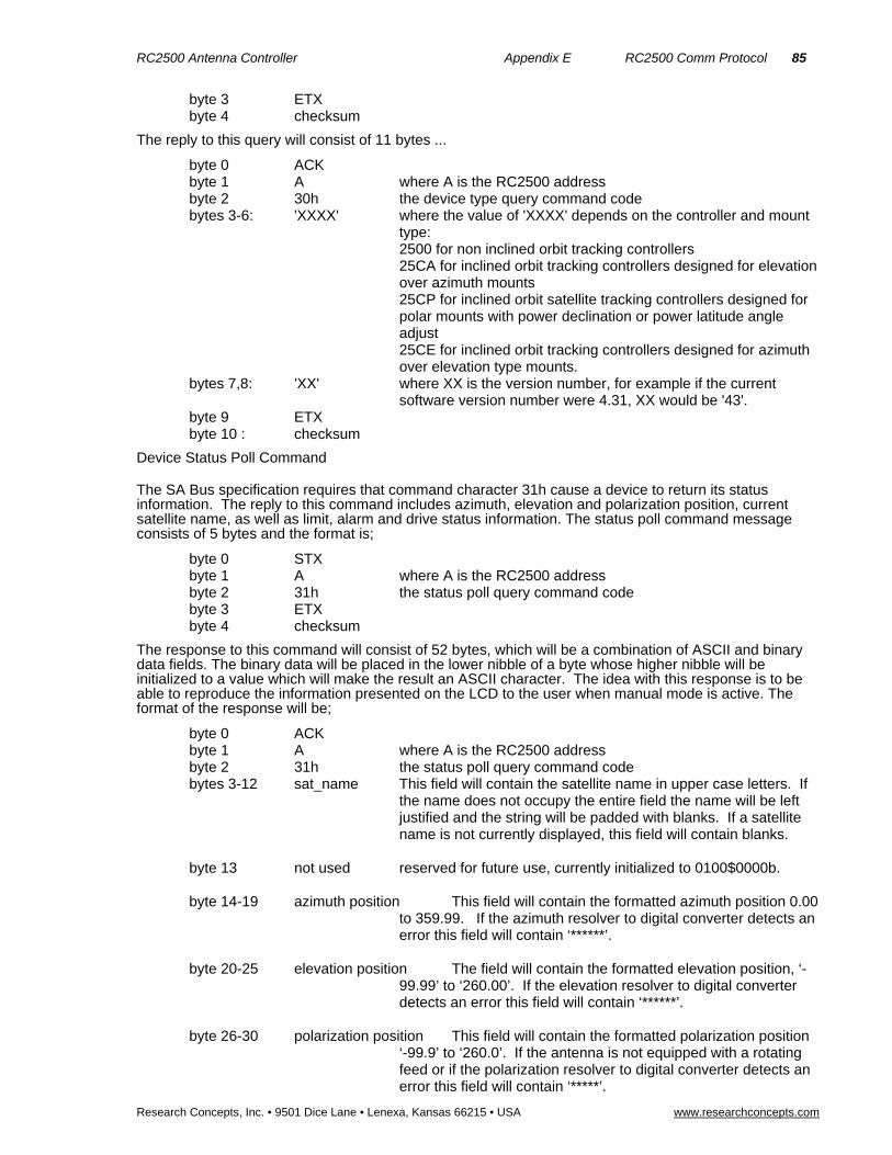
RC2500 Antenna Controller Appendix E RC2500 Comm Protocol 85
Research Concepts, Inc. • 9501 Dice Lane • Lenexa, Kansas 66215 • USA www.researchconcepts.com
byte 3 ETX byte 4 checksum
The reply to this query will consist of 11 bytes ...
byte 0 ACK byte 1 A where A is the RC2500 address byte 2 30h the device type query command code bytes 3-6: 'XXXX' where the value of 'XXXX' depends on the controller and mount
type: 2500 for non inclined orbit tracking controllers 25CA for inclined orbit tracking controllers designed for elevation
over azimuth mounts 25CP for inclined orbit satellite tracking controllers designed for
polar mounts with power declination or power latitude angle adjust
25CE for inclined orbit tracking controllers designed for azimuth over elevation type mounts.
bytes 7,8: 'XX' where XX is the version number, for example if the current software version number were 4.31, XX would be '43'.
byte 9 ETX byte 10 : checksum
Device Status Poll Command
The SA Bus specification requires that command character 31h cause a device to return its status information. The reply to this command includes azimuth, elevation and polarization position, current satellite name, as well as limit, alarm and drive status information. The status poll command message consists of 5 bytes and the format is;
byte 0 STX byte 1 A where A is the RC2500 address byte 2 31h the status poll query command code byte 3 ETX byte 4 checksum
The response to this command will consist of 52 bytes, which will be a combination of ASCII and binary data fields. The binary data will be placed in the lower nibble of a byte whose higher nibble will be initialized to a value which will make the result an ASCII character. The idea with this response is to be able to reproduce the information presented on the LCD to the user when manual mode is active. The format of the response will be;
byte 0 ACK byte 1 A where A is the RC2500 address byte 2 31h the status poll query command code bytes 3-12 sat_name This field will contain the satellite name in upper case letters. If
the name does not occupy the entire field the name will be left justified and the string will be padded with blanks. If a satellite name is not currently displayed, this field will contain blanks.
byte 13 not used reserved for future use, currently initialized to 0100$0000b. byte 14-19 azimuth position This field will contain the formatted azimuth position 0.00
to 359.99. If the azimuth resolver to digital converter detects an error this field will contain ‘******’.
byte 20-25 elevation position The field will contain the formatted elevation position, ‘-
99.99’ to ‘260.00’. If the elevation resolver to digital converter detects an error this field will contain ‘******’.
byte 26-30 polarization position This field will contain the formatted polarization position
‘-99.9’ to ‘260.0’. If the antenna is not equipped with a rotating feed or if the polarization resolver to digital converter detects an error this field will contain ‘*****’.

86 RC2500 Antenna Controller Appendix E RC2500 Comm Protocol
Research Concepts, Inc. • 9501 Dice Lane • Lenexa, Kansas • 66215 • USA www.researchconcepts.com
byte 31 azimuth, elevation, and polarization limits, binary data 7 6 5 4 3 2 1 0 0 1 A B $ C D E F
A ‘0’ in a bit position implies that the antenna is not at the limit, a ‘1’ in the bit position implies that the antenna is at the limit. Here is the mapping of bit positions to the limits ....
A - Azimuth Clockwise B - Azimuth Counterclockwise C - Elevation Up D - Elevation Down E - Polarization Clockwise F - Polarization Counterclockwise If the controller is designed to interface to an outdoor unit which
just reports a summary limit indication (such as the Vertex 7134), bit position F will report the status of the summary limit.
byte 32 polarization equipment and display status code - binary data 7 6 5 4 3 2 1 0 0 1 X X $ Y Z Z Z
where ‘XX’ is ... 00 if a rotating feed is not present in the system 01 if a single port rotating feed is present in the system 10 if a dual port rotating feed is present in the system. A dual
port rotating feed can simultaneously receive both horizontally and vertically polarized signals.
where ‘Y’ is ... 0 if polarization movements are not allowed. 1 if polarization movements are allowed. Discussion - The ‘Y’ field described above only contains
meaningful data when TRACK mode is active. Polarization movement is not allowed during a TRACK mode peaking operation. If a polarization operation occurs while peaking the antenna the peak obtained may not be reliable. If a ‘go to’ H or V polarization command is received via the serial port the controller will execute the command after the peaking operation is completed. The reply to the ‘go to’ command will be an ACK.
A polarization jog command which is received during a peaking
operation will not be registered and executed later. The reply to the command will be a NAK.
where ‘ZZZ’ is ... 000 if the ‘H' polarization code is displayed 001 if the 'h' polarization code is displayed 010 if the 'V' polarization code is displayed 011 if the 'v' polarization code is displayed 100 if no polarization code is displayed

RC2500 Antenna Controller Appendix E RC2500 Comm Protocol 87
Research Concepts, Inc. • 9501 Dice Lane • Lenexa, Kansas 66215 • USA www.researchconcepts.com
byte 33 azimuth movement/alarm status - binary data 7 6 5 4 3 2 1 0 0 1 0 S $ X X X X
where ‘S’ is ... 0 if the axis is configured for slow speed movement 1 if the axis is configured for fast speed movement where ‘XXXX’ is ... 0000 no alarms or movement 0010 ccw movement pending 0011 cw movement pending 0100 ccw movement in progress 0101 cw movement in progress 0111 an auto move is in progress 1000 off axis alarm active. This alarm code is reported if an
elevation alarm is active. The controller has a single output which disables both the azimuth and elevation drives. If a jammed, sensor, or runaway alarm is detected for the elevation axis the controller will disable the elevation drive which also has the effect of disabling the azimuth drive. When this occurs the azimuth off axis alarm activates.
1001 sensor direction alarm active 1010 runaway alarm active 1011 jammed alarm active 1100 drive alarm active. This is triggered by an overcurrent
condition.
Note - Higher value status codes have priority over lower value ones, i.e. if as part of an auto move command the antenna is moving clockwise the status will be reported as 'auto move in progress' rather than 'clockwise movement in progress'.
byte 34 elevation movement/alarm status - binary data 7 6 5 4 3 2 1 0 0 1 0 S $ X X X X
where ‘S’ is ... 0 if the axis is configured for slow speed movement 1 if the axis is configured for fast speed movement where ‘XXXX’ is ... 0000 no alarms or movement 0010 ccw movement pending 0011 cw movement pending 0100 ccw movement in progress 0101 cw movement in progress 0111 an auto move is in progress 1000 off axis alarm active. This alarm code is reported if an
azimuth alarm is active. The controller has a single output which disables both the azimuth and elevation drives. If a jammed, sensor, or runaway alarm is detected for the azimuth axis the controller will disable the azimuth drive which also has the effect of disabling the elevation drive. When this occurs the elevation off axis alarm activates.
1001 sensor direction alarm active 1010 runaway alarm active 1011 jammed alarm active

88 RC2500 Antenna Controller Appendix E RC2500 Comm Protocol
Research Concepts, Inc. • 9501 Dice Lane • Lenexa, Kansas • 66215 • USA www.researchconcepts.com
1100 drive alarm active. This is triggered by an overcurrent condition.
Note - Higher value status codes have priority over lower value ones, i.e. if as part of an auto move command the antenna is moving down status will be reported as 'auto move in progress' rather than 'down movement in progress'.
byte 35 polarization movement/alarm status - binary data 7 6 5 4 3 2 1 0 0 1 0 S $ X X X X
where ‘S’ is ... 0 if the axis is configured for slow speed movement 1 if the axis is configured for fast speed movement where ‘XXXX’ is ... 0000 no alarms or movement 0010 ccw movement pending 0011 cw movement pending 0100 ccw movement in progress 0101 cw movement in progress 0111 an auto move is in progress 1000 off axis alarm active. This alarm code is currently not
supported for the polarization axis. 1001 sensor direction alarm active 1010 runaway alarm active 1011 jammed alarm active 1100 drive alarm active. This is triggered by an overcurrent
condition.
Note - Higher value status codes have priority over lower value ones, i.e. if as part of an auto move command the antenna is moving clockwise the status will be reported as 'auto move in progress' rather than 'clockwise movement in progress'.
byte 36 alarm code - binary data 0 1 A A $ A A A A 5 4 3 2 1 0
A5 .. A0 specify the alarm code (0-63). Alarm messages flash on the bottom row of the display. Here are the alarm codes which have been defined ...
0 - No alarm active 1 - Low battery 2 - Antenna azimuth alarm active. 3 - Antenna elevation alarm active. 4 - Maintenance indication from the outdoor unit. 5 - Emergency stop detected at the outdoor unit. 6 - Summary limit from outdoor unit. A version of the RC2500 is
available which is designed to interface with outdoor units which report a single summary limit indication back to the controller. With a single summary limit indication the controller has no way of determining which limit has activated. On these versions of the controller when a summary limit is detected a message is flashed on the bottom line of the display by the alarm display system. This is not really an alarm condition.
12 - The communications port parameters are corrupted (in which case it is doubtful that this reply would make it back to the host).
14 - The inclined orbit satellite tracking parameters are corrupted.

RC2500 Antenna Controller Appendix E RC2500 Comm Protocol 89
Research Concepts, Inc. • 9501 Dice Lane • Lenexa, Kansas 66215 • USA www.researchconcepts.com
15 - The antenna and/or receiver parameters are corrupted. 16 - Time or Date corrupted. 17 - The az/el/pol display offsets or sensor direction flags are
corrupted. 18 - The polarization equipment code or polarization auto move
parameters are corrupted. 19 - Antenna polarization alarm detected. 20 - The azimuth and/or elevation auto move parameters or the
simultaneous az/el flag is corrupted. On versions of the controller designed to interface with the Harris 9135 outdoor enclosure this alarm code will be asserted if the azimuth and/or elevation slow speed parameters are corrupted.
byte 37: Track Mode submode or error status and track frequency band - binary data 7 6 5 4 3 2 1 0 0 1 B B $ S S S S
where ‘BB’ is ... 00 - C band 01 - Ku band 11 - L band and where ‘SSSS’ is ... 0000 - track mode not active 0001 - track setup submode active 0010 - track auto mode entry 0011 - step track submode active 0100 - track auto search submode active 0101 - program track submode active 0110 - track manual search submode active 1000 - track jammed error 1001 - track limit error 1010 - track drive error 1011 - track peak limit error 1100 - track geo position error 1101 - track system error track 1110 - track checksum error bytes 38 - 41: AGC Channel 1 The AGC channel 1 voltage is represented internally by a
numeric value between 0 and 1023. This numeric value is converted to an ASCII string - ‘ 0’ and ‘1023’. The most significant digit will be placed in byte 38 and the least significant digit will be placed in byte 41. The string will be right justified and padded with blanks (on the left).
bytes 42 - 45: AGC Channel 2 The AGC channel 2 voltage is represented internally by a
numeric value between 0 and 1023. This numeric value is converted to an ASCII string - ‘ 0’ and ‘1023’. The most significant digit will be placed in byte 42 and the least significant digit will be placed in byte 45. The string will be right justified and padded with blanks (on the left).
bytes 46 - 49: Reserved - At this time these bytes are initialized to 0100$0000b. byte 50: ETX byte 51: checksum
Query Name Command

90 RC2500 Antenna Controller Appendix E RC2500 Comm Protocol
Research Concepts, Inc. • 9501 Dice Lane • Lenexa, Kansas • 66215 • USA www.researchconcepts.com
This query command instructs the RC2500 to send back to the host computer the name of a satellite stored in non-volatile memory (via the controller’s SETUP mode) and the total number of satellites stored in non-volatile memory. The command contains the index of the desired entry in the satellite list. A maximum of 30 satellites can be stored in memory. This query command contains 7 bytes and the format is;
byte 0 STX byte 1 A where A is the RC2500 address byte 2 35h the query name command code bytes 3,4 'XX' where XX is the index of the satellite name being requested.
Normally this would be '01' the first time through and then incremented until the 'YY' (YY being the last entry in the list) satellite name is read. The maximum possible range for XX and YY is 1 through 30.
byte 5 ETX byte 6 checksum the checksum
The normal response to this query command contains 19 bytes and the format is as follows;
byte 0 ACK byte 1 A where A is the RC2500 address byte 2 35h the query name command code bytes 3,4 'XX' where XX is the index of the satellite name being requested. bytes 5,6 'YY' where YY is the total number of satellite names contained in the
list. bytes 7-16: sat name This field will contain the satellite name. The name will be in
capital letters and normally be left justified. The only time the satellite name will not be left justified is if the user selected the USER entry from SETUP mode and manually entered blank characters before the satellite name.
byte 17: ETX byte 18 : checksum the checksum
Note that if entry 'XX' does not exist in the list (or the list has no entries) the NAK reply will be sent back to the host.
Auto Move Command
This command causes the controller to automatically position the antenna in either azimuth and elevation and/or polarization. The command contains 16 bytes. Here is the format;
byte 0 STX byte 1 A where A is the RC2500 address byte 2 32h the auto move command code byte 3 polarization This field can specify 'H', 'V', ' ' (blank), or 'P'. byte 4-13 sat_name/position This field specifies the satellite name or a target azimuth
and elevation or polarization position. byte 14 : ETX byte 15 : checksum
The normal reply to this command will be the same as the reply to the status poll query except that the command code field will be '32h'. Note that if the satellite name is not found or target positions for a move to a target position are not specified properly a NAK reply will be sent to the host.
The Auto Move command has 3 forms.
Form 1. If the sat_name/position field contains the name of a satellite saved via the controller's SETUP mode the controller will position the antenna at the azimuth and elevation positions associated with that satellite. The satellite name should be in capital letters, left justified and padded on the right with blanks in the sat_name/position field. Note that the satellite name specified in the command must exactly match a satellite name stored in the controller's non-volatile memory.

RC2500 Antenna Controller Appendix E RC2500 Comm Protocol 91
Research Concepts, Inc. • 9501 Dice Lane • Lenexa, Kansas 66215 • USA www.researchconcepts.com
With this form of the command, the polarization field may contain either 'H', 'V', or ' ' (a blank, 20 hex or 32 decimal). If an 'H' or a 'V' is specified, in addition to positioning the antenna in azimuth and elevation, the polarization control device will be commanded to go to the position associated with either the horizontal (if 'H' is specified) or vertical (if 'V' is specified) polarization specified for the satellite. If the field contains a blank the polarization is not changed. For example, this command with 'H' in the polarization field and 'SBS 6 ' in the sat_name/position field will specify an auto move to SBS 6 and the polarization will be adjusted to horizontal for the SBS 6 satellite.
Form 2. If the sat_name/position field contains a valid pair of azimuth and elevation sensor position counts the antenna will move to the position specified. The first 5 characters of the sat_name/position field specify the azimuth position (azimuth sub-field) and the last five characters specify the elevation position (elevation sub-field). Within each of the sub-fields the position must be right justified and left padded with zeroes. For example, a sat_name/position field value of '0152500750' specifies an azimuth position of 1525 counts and an elevation position of 750. For this form of the auto move command, only the blank character is accepted in the polarization field. Note that the position must be specified in position counts and not in an angle format. See the discussion below on the Mapping of Sensor Position Counts to Displayed Angle.
Form 3. If the polarization field contains the 'P' character, the command is interpreted as a go_to_polarization command. For this form of the command, the first 5 characters of the sat_name/position field specify the target polarization position in the controller's internal polarization position representation (polarization sub-field). The polarization position in the polarization sub-field must be right justified and left padded with zeroes. The second 5 characters of the sat_name/position field must contain '00000'. For example, if the sat_name/position field contains '0050000000' the polarization control device is commanded to adjust the polarization to a position of 500. See the next paragraph for more information on the relationship between sensor position and displayed angle.
Mapping of Sensor Position Counts to Displayed Angle
The RC2500 is designed to interface with antennas equipped with resolver type position sensors. The resolver is excited by an AC voltage. The angle of the resolver shaft modulates the amplitude of a pair of quadrature output signals. A resolver to digital converter (rdc) takes as its input the quadrature outputs of the resolver as well as the excitation voltage and produces a binary output which is read by the RC2500’s micro-controller The RC2500 is equipped with a 16 bit resolver to digital converter. A 16 bit rdc produces 65536 (or 216) unique binary output values, which are represented internally in the controller as numbers in the range of 0 through 65535. It is these position counts which are passed to the controller in Form 2 and Form 3 of the Auto Move command. To convert from position counts to shaft angle use the following formula ..
Resolver_Shaft_Angle = (Position_Count * 360.0) / 65536
Note that the resolver output wraps (or rolls over) from 360.0 to 0.0 degrees if the shaft is rotated 360 degrees. The resolver must be mechanically attached to the antenna so that this wrapping does not occur within the antenna’s normal range of movement (to enable the controller to calculate which direction to move to reach a target position). For this reason (and to facilitate calibration of the resolvers) an offset angle is added to the calculated resolver angle. The sum of the resolver shaft angle and the offset angle may be adjusted by adding or subtracting 360 degrees so that the resulting angle lies in a desired range of values. It is this adjusted value which is displayed. Each axis has it’s own unique offset angle. These angles are specified via the Azim Display Offset, Elev Display Offset, and Pol Display Offset CONFIG mode items. The range of the ‘Display Offset CONFIG mode items are -179.99 to 180.00. Each axis will considered separately.
For the azimuth axis, the display angle will be the sum of the azimuth resolver shaft angle and the Azim Display Offset CONFIG mode item adjusted by either adding or subtracting 360.0 degrees so that the resulting angle lies in the range of 0.00 to 360.00 degrees.
For the elevation axis, the display angle will be the sum of the elevation resolver shaft angle and the Elev Display Offset CONFIG mode item adjusted by either adding or subtracting 360.0 degrees so that the resulting angle lies in the range of -99.99 to 260.00.
For the polarization axis, the display angle will be the sum of the polarization resolver shaft angle and the Pol Display Offset CONFIG mode item adjusted by either adding or subtracting 360.0 degrees so that the resulting angle lies in the range of -99.9 to 260.0.
Azimuth/Elevation/Polarization Jog Command

92 RC2500 Antenna Controller Appendix E RC2500 Comm Protocol
Research Concepts, Inc. • 9501 Dice Lane • Lenexa, Kansas • 66215 • USA www.researchconcepts.com
This command jogs the antenna in azimuth, elevation, or polarization. The command contains 11 bytes. Here is the format of the command;
byte 0 STX byte 1 A where A is the RC2500 address byte 2 33h the command code byte 3 direction This field can specify 'C', 'W', 'D', 'U', O, L, or 'X' where ... C refers to azimuth Counter clockwise, W refers to azimuth clockWise, D refers to elevation Down, U refers to elevation Up, O refers to polarization cOunter clockwise, L refers to polarization cLockwise, and X means stop all movement. byte 4 speed This field specifies the jog speed, either 'F' (Fast) or 'S' (Slow).
Note that this field must contain a valid value even if the direction field specifies 'X' (Stop).
bytes 5-8 : duration This field specifies the duration of the jog command in
milliseconds. The valid range of values for this field is '0000' to '9999'. As a practical matter, the resolution of the timer used to time the move is approximately 175 milliseconds, so any move will be for a time interval equal to a multiple of approx. 175 milliseconds. Note that this command must contain a valid value even if the direction field specifies 'X' (Stop).
byte 9 ETX byte 10 : checksum the checksum
If this command can be executed, the reply to this command will be the same as the reply to the status poll query command except the command code will be '33h'. A NAK reply will be sent to the host if the direction specifies C, W, U, D, O, or L and the limit input associated with the axis and direction specified by the command is asserted (only for versions of the controller which support individual limits). Note that the controller can only support a remote jog about a single axis. For example, if a remote jog is in progress about the azimuth axis and a remote elevation jog command is received (that can be executed), the azimuth jog will terminate regardless of the duration specified for the remote azimuth jog. A NAK reply will also be sent to the host if polarization movement is specified and the Pol Control Equipment Code CONFIG mode item is set to 0 (No Pol Control). If the direction byte contains ‘X’ all antenna movement will stop. If TRACK mode is active and the direction byte specifies ‘X’, ‘C’, ‘W’, ‘D’, or ‘U’ REMOTE mode will receive control and all tracking will cease. If TRACK mode is active and a peaking or search operation is in progress the NAK reply will be returned to the host.
Polarization Command
The following command specifies a move to a preset polarization position. The command contains 6 bytes.
The format of the command is as follows;
byte 0 STX byte 1 A where A is the RC2500 address byte 2 34h the command code byte 3 'X' this field will specify either ‘H’ or ‘V’ where ... H specifies that the controller drive the polarization to the
horizontal polarization position associated with the satellite that was the last target of an auto move operation.
V specifies that the controller drive the polarization to the vertical
polarization position associated with the satellite that was the last target of an auto move operation.

RC2500 Antenna Controller Appendix E RC2500 Comm Protocol 93
Research Concepts, Inc. • 9501 Dice Lane • Lenexa, Kansas 66215 • USA www.researchconcepts.com
byte 4 ETX byte 5 checksum
The reply to this command will be the same as the reply to the status poll query command except the command code will be 34h. Note that the NAK reply will be sent back to the host if there are no satellites available in the RC2500’s memory or if the Pol Control Equipment Code CONFIG mode item is set to 0 (No Pol Control). Note that if the Pol Control Equipment Code is set to 2 (2 Port Feed) there is only one polarization position associated with the satellite and receipt of this command with either the ‘H’ or ‘V’ argument will result in a move to the single polarization position associated with the satellite. If TRACK mode is active and a peaking or search operation is in progress this command will not be executed until after the peaking or search operation terminates. If this occurs the normal acknowledgment will be sent to the host.
Miscellaneous Command
This command performs miscellaneous functions. Here is the format of the command.
byte 0 STX byte 1 A where A is the RC2500 address byte 2 36h the miscellaneous command code byte 3 'X' the sub-command code byte 4 'Y' the sub-command parameter byte 5 ETX byte 6 checksum The sub-command code 'X' can have the following values ... 'X' = 'R' This specifies the azimuth or elevation drive reset command.
This accomplishes the same function as the RESET mode of the RC2500: it allows the user to reset the azimuth, elevation, or polarization alarms. When the sub-command code is 'R', the sub-command parameter 'Y' must be either 'A', 'E', or 'P' (for azimuth, elevation, or polarization respectively) to specify which axis will be reset. If the 'P' command is specified, the command will be accepted only if the Pol Control Equipment Code CONFIG mode item is set to 1 (ONE PORT) or 2 (TWO PORT).
'X' = 'T' This sub-command is used to reset track mode errors (sub-
command parameter 'Y' = R). When the TRACK mode ERROR sub-mode is active this command will cause the ERROR sub-mode to terminate. The controller will react as if TRACK mode was activated via AUTO mode. Note that if a system error is active (an error message flashing on the bottom row of the display) the condition which generated the system error must be rectified or the controller will probably return to the TRACK mode ERROR sub-mode. This sub-command can also be used to switch frequency bands when a dual band satellite is being tracked. A sub-command parameter of 'C' will specify C band and a sub-command parameter of 'K' will specify K band. The reply to this command will be a NAK if TRACK mode is not active, the satellite being tracked was not specified as a dual band satellite (when the track was initiated via SETUP mode), or if track polarization movement is not allowed (see byte 32 of the device status poll command). If polarization movements are not allowed the controller is either peaking the antenna or performing a search. Changing the band during a peaking operation or search can cause the antenna to not accurately peak the antenna.

94 RC2500 Antenna Controller Appendix E RC2500 Comm Protocol
Research Concepts, Inc. • 9501 Dice Lane • Lenexa, Kansas • 66215 • USA www.researchconcepts.com
The reply to this command will be the same as the reply to the status poll query except the command code will be '36h'.
C Program
A C program, RC2500_A.EXE, has been written which allows a user to send commands to the RC2500 via the serial port. The program runs on an IBM PC (or compatible) and was designed to aid the software developer who is writing programs to control the RC2500 or an installer verifying the serial port wiring. All of the commands listed above can be sent to the controller. The program features three windows. In the top window the user is prompted for commands to send to the controller. In the middle window, the command strings sent to the controller are displayed. The bottom window displays all characters received from the controller. The source code is included with the program and a developer may examine and freely use any of the routines. A disk containing this program is included with each controller. Because the program displays all characters both sent to and received from the controller it is useful for performing loopback tests to verify the host computer serial port wiring.
Message Delimiters
Here are the delimiters used with SA bus messages, along with their value’s in hex and decimal.
ASCII name Hex value decimal value STX 2 2 ETX 3 3 ACK 6 6 NAK 15 21

RC2500 Antenna Controller Appendix F Satellite Inclination 95
Research Concepts, Inc. • 9501 Dice Lane • Lenexa, Kansas 66215 • USA www.researchconcepts.com
Appendix F – Estimating Satellite Inclination Satellite Inclination refers to the angle of the satellite orbit with the earth’s equatorial plane. Normal satellite station-keeping maneuvers maintain the inclination near zero and the longitude to the assigned position. Satellite fuel reserves may be extended if it is allowed to incline naturally and station-keeping is maintained only in longitude. Whereas a geostationary satellite appears fixed in space, the apparent position of a satellite in an inclined orbit varies with time.
The pull of lunar and solar gravity combine to cause the inclination to naturally increase by 0.75 to 0.95 degrees per year. The figure below shows increasing inclination at the rate of 0.9 degrees per year for satellites with various staring inclinations.
The Table below lists selected satellites, their longitude and inclination as of June 1998. To use the figure with the tabular data: 1) Locate the June 1998 inclination from the table. 2) Find that point on the left scale of the figure. 3) Move from that point parallel to the diagonal plotted lines out to the current date. 4) The current estimated inclination is now read from the left scale of the figure. As an example estimate the inclinatioin of InSat 2A in March 2002. InSat 2A has a starting inclination of 0.8444 degrees. This point is shown on the graph with an ‘x’. For the year 2002 and 1/4th, the inclination is shown by a ‘*’, about 4.2 degrees.
Common Name Longitude Inclination USA 115/Milstar 2 (US) 4.0E ? Eutelsat 2F4 (EUTE) 7.0E 0 Eutelsat 2F2 (EUTE) 10.0E 0 Eutelsat 2F1 (EUTE) 13.0E 0 Italsat 2 Italy) 13.1E 0.0929 Italsat 1 (Italy) 14.4E 1.0476 Eutelsat 2F3 (EUTE) 16.0E 0 Astra 1A (Lux) 19.2E 0 Eutelsat 1F5/ECS 5 (EUTE) 21.5E 3.1668 DFS 3 (Germany) 23.5E 0 Eutelsat 1F4/ECS 4 (EUTE) 25.5E 3.9538 Gorizont 20 (CIS) 25.7E 4.822 Arabsat 2A (Arabsat) 26.0E 0 DFS 2/Kopernikus (Germany) 28.2E 0 Arabsat 2B(Arabsat) 30.5E 0
Estimated Satellite Inclination
0123456789
10
1998 1999 2000 2001 2002 2003 2004 2005 2006 2007 2008 2009 2010
Year
Incl
inat
ion
, deg
rees

96 RC2500 Antenna Controller Appendix F Satellite Inclination
Research Concepts, Inc. • 9501 Dice Lane • Lenexa, Kansas • 66215 • USA www.researchconcepts.com
Turksat 1B (Turkey) 31.3E 0 Intelsat 510 (ITSO) 33.0E 4.5278 Raduga 28 (CIS) 35.0E 3.5556 USA 65/DSP F15 (US) 37.4E ? Gorizont 31 (CIS) 40.5E 0.3692 Turksat 1C (Turkey) 42.0E 0 Raduga 1-3 (CIS) 48.7E 1.804 Gorizont 32 (CIS) 53.0E 0.1664 Arabsat 1C 55.0E 0 USA 44/DSCS 3A2 (US) 57.0E ? Intelsat 703 (ITSO) 57.0E 0 Intelsat 604 (ITSO) 60.0E 0 USA 97/DSCS 3B10 (US) 60.0E ? Intelsat 602 (ITSO) 62.0E 0 Intelsat 804 (ITSO) 64.0E 0 Intelsat 704 (ITSO) 66.0E 0 PanAMSat 4/PAS 4 (US) 68.5E 0 Raduga 32 (CIS) 70.0E 1.1374 Intelsat 505 (ITSO) 71.0E 6.7181 USA 95/UFO 2 (US) 71.1E 3.3863 Ops 6391/FLSatCom F1(US) 72.7E 13.666 USA 111/UFO 5 (US) 72.8E 3.9048 InSat 2A (India) 73.9E 0.8444 Apstar 2R (PRC) 76.5E 0 Luch 1-1 (CIS) 77.1E 1.012 Thaicom 2 (Thailand) 78.5E 0 Thaicom 3 (Thailand) 78.5E 0 Cosmos 2319 (CIS) 79.6E 0.5984 Gorizont 24 (CIS) 80.0E 3.6791 Express 2 (CIS) 79.9E 0 Zhongxing 1/DFH-2A1 (PRC) 81.5E 3.924 Insat 1D(India) 83.0E 0 Raduga 30 (CIS) 83.8E 2.0917 TDRS F3 (US) 85.7E 3.9186 Gorizont 28 (CIS) 90.0E 2.0652 Measat 1 (Malaysia) 91.5E 0 Insat 2B (India) 93.5E 0 Insat 2C (India) 93.5E 0 Gorizont 27 (CIS) 96.3E 2.8027 Zhongxing 3/DFH-2A3 (PRC) 97.8E 2.2434 AsiaSat 2 (AC) 100.5E 0 Gorizont 25 (CIS) 103.0E 3.3392 Asisat 1 (AC) 105.5E 0 Palapa B2R (Indonesia) 108.0E 0 BS 3N (Japan) 108.8E 0 Zhongxing 2/DFH2-A2/PRC 110.4E 2.4338 Palapa C2 (Indonesia) 113.0E 0 Zhongxing 5/Chinasat 5 (PRC) 115.3E 1.8272 Koreasat1/Mugunghwa1 (Korea) 116.0E 0 Koreasat2/Mugunghwa2 (Korea) 116.0E 0 Palapa B4 (Indonesia) 117.8E 0 Thaicom 1 (Thailand) 120.0E 0 Gorizont 30/Rimsat 2 (CIS) 122.0E 1.7451 JCSAT 4 (Japan) 124.0E 0 Zhongxing 8/DFH3-2 (PRC) 125.0E 0 Raduga 27 (CIS) 127.5E 4.4957 JCSAT 3 (Japan) 128.0E 0 N-Star 1 (Japan) 131.8E 0 Apstar 1A (PRC) 134.0E 0 N-Star 2 (Japan) 135.9E 0 Apstar 1 (PRC) 138.0E 0 Gorizont 22 (CIS) 140.0E 4.4788 Agila 1/Palapa B2P(Phillippines) 140.5E 1.866 Superbird C (Japan) 144.0E 0 Gorizont 21 (CIS) 145.0E 4.5549 USA 39/DSP F14 (US) 145.4E ? Agila 2/Mabuhay 1 (Phillippines) 146.0E 0 Measat 2 (Malaysia) 148.0E 0

RC2500 Antenna Controller Appendix F Satellite Inclination 97
Research Concepts, Inc. • 9501 Dice Lane • Lenexa, Kansas 66215 • USA www.researchconcepts.com
JCSAT 5 (Japan) 150.0E 0 Palapa C! (Indonesia 150.5E 0 Optus A3/Aussat K3 (Australia) 151.9E 2.0891 JCSAT 2 (Japan) 154.0E 0 Optus B3 (Australia) 156.05 0 Intelsat 503 (ITSO) 156.8E 7.2689 Superbird A (Japan) 158.0E 0 Gorisont 29/Rimsat 1 (CIS) 161.0E 2.017 Superbird B (Japan) 162.0E 0 Optus A2/Aussat 2 (Australia) 163.9E 3.8774 USA 130/DSP F18 (US) 165.0E 0 PanAmSat 2/PAS 2 (US) 169.0E 0 OPS 6394/FltSatCom F4 (US) 171.5E 11.8686 UHF-F8 (US) 172.0E 0 Intelsat 802 (ITSO) 174.0E 0 USA 93/DSCS 3B9 (US) 175.0E ? Intelsat 702(ITSO) 177.0E 0 USA 12/DSCS 3B5 (US) 180.0E ? Intelsat 701 (ITSO) 180.0E 0 USA 108/UFO 4 (US) 177.6W 3.8322 Intelsat 513 (ITSO) 177.0W 2.2826 TDRS F5 (US) 174.3W 0 USA 138/UFO 8 (US) 172.0W 0 TDRS F7 (US) 171.3W 2.1958 Raduga 25 (CIS) 170.0W 5.0361 Aurora II/Satcom C5 (US) 139.0W 0 Satcom C1 (US) 137.0W 0 USA 78/DSCS 3814 (US) 135.0W/i ? Satcom C4 (US) 135.0W 0 Galaxy 1R (US) 133.0W 0 Satcom C3 (US) 131.0W 0 DSCS 3A1 (US) 129.9W 6.4707 Galaxy 5 (US) 125.0W 0 Galaxy 9 (US) 123.0W 0 SBS 5 (US) 123.0W 0 USA 99/Milstar 1 (US) 120.0W 0 Telestar 303/3D (US) 120.0W 2.3654 Echostar 1 (US) 119.0W 0 Morelos 2 (Mexico) 116.8W 0 Solidardad 2 (Mexico) 113.0W 0 Anik E1 (Canada) 111.1W 0 Solidaridad 1 (Mexico) 109.2W 0 Anik E2 (Canada) 107.3W 0 GStar 1 (US) 105.0W 1.6489 GStar 4 (US) 105.0W 0 USA 114/UFO 6 (US) 104.5W 3.9984 GE 1 (US) 103.0W 0 USA107/DSP F17 (US) 103.2W ? DBS 1 (US) 101.0W 0 Spacenet 4 (US) 101.0W 0 ACTS (US) 99.9W 0 USA 20/FltSatCom F& (US) 99.0W 4.2122 GOES 7 (US) 98.3W 4.4766 Galaxy 6 (US) 74.0W 0 Telstar 5 (US) 97.0W 0 Galaxy 3R (US) 95.0W 0 SBTS AZ (Brazil) 92.0W 0 Galaxy 7 (US) 91.0W 0 Telstar 402R (US) 89.0W 0 GE 3 (US) 87.0W 0 GE 2 (US) 85.0W 0 Brasilsat B3 (Brazil) 84.0W 0 Spacenet 3R (US) 83.0W 0 Satcom K2 (US) 81.0W 0.9439 SBTS 1 (Brazil) 79.0W 2.8546 SBS 4 (US) 77.0W 4.1119 Comstar D4 (US) 75.8W 9.9315 SBS 6 (US) 74.0W 0

98 RC2500 Antenna Controller Appendix F Satellite Inclination
Research Concepts, Inc. • 9501 Dice Lane • Lenexa, Kansas • 66215 • USA www.researchconcepts.com
Nahuel 1A (Argentina) 71.8W 0 Brazilsat B1 (Brazil) 70.0W 0 Brazilsat B2 (Brazil) 65.0W 0 Intelsat 512 (ITSO) 55.5W 3.3054 Intrelsat 706 (ITSO) 53.0W 0 USA 113/DSCS 3B4 (US) 52.5W ? Intelsat 709 (ITSO) 50.0W 0 TDRS 1 (US) 49.4W 9.9691 TDRS F6 (US) 47.0W 0 PanAmSat 1/PAS 1 (US) 45.0W 0 PanAmSat 6/PAS 6 (US) 43.0W 0 USA 11/DSCS 387 (US) 42.5W ? TDRS F4 (US) 41.0W 1.4035 Intelsat 502 (ITSO) 40.5W 7.5864 Intelsat 806 (ITSO) 40.5W 0 Orion 1 (US) 37.5W 0 Columbia 515 (ITSO) 37.5W 0.7002 Intelsat 601 (ITSO) 34.5W 0 Skynet 4A (UK) 34.0W 3.3484 Hispasat 1A (Spain) 30.0W 0 Hispasat 1B (Spain) 30.0W 0 Intelsat 506 (ITSO) 29.7W 5.8389 Intelsast 801 (ITSO) 28.0W 0 Intelsat 605 (ITSO) 27.5W 0 Intelsat 603 24.5W 0 USA 127/UFO 7 (US) 23.7W 4.2787 USA 46/FltSatCom F8 (US) 22.8W 2.2468 Intelsat K (ITSO) 21.5W 0 Intelsat 803 (ITSO) 21.5W 0 NATO 3D (NATO) 18.3W 5.2312 Intelsat 705 (ITSO) 18.0W 0 NATO 4A (NATO) 17.7W 2.2174 Luch 1 (CIS) 16.0W 0.2749 USA 104/UFO 3 (US) 14.5W 3.3217 Express 1 (CIS) 14.0W 0 Cosmos 2291 (CIS) 13.4W 1.3763 USA 82/DSCS 3B12 (US) 12.0W 0 Gorizont 26 (CIS) 11.0W 3.0548 USA 98/NATO 4B NATO 10.0W 1.881 USA 75/DSP F16 (US) 8.9W ? Amos 1 (Isreal) 4.0W 0 Intelsat 707 (ITSO) 1.0W 0
Notes:

RC2500 Antenna Controller Appendix G Schematics/ PCB Layouts 99
Research Concepts, Inc. • 9501 Dice Lane • Lenexa, Kansas 66215 • USA www.researchconcepts.com
Appendix G – Schematics/ PCB Layouts
Processor Board Layout

100 RC2500 Antenna Controller Appendix G Schematics/ PCB Layouts
Research Concepts, Inc. • 9501 Dice Lane • Lenexa, Kansas • 66215 • USA www.researchconcepts.com
Processor Board – Core

RC2500 Antenna Controller Appendix G Schematics/ PCB Layouts 101
Research Concepts, Inc. • 9501 Dice Lane • Lenexa, Kansas 66215 • USA www.researchconcepts.com
Processor Board – Analog Input
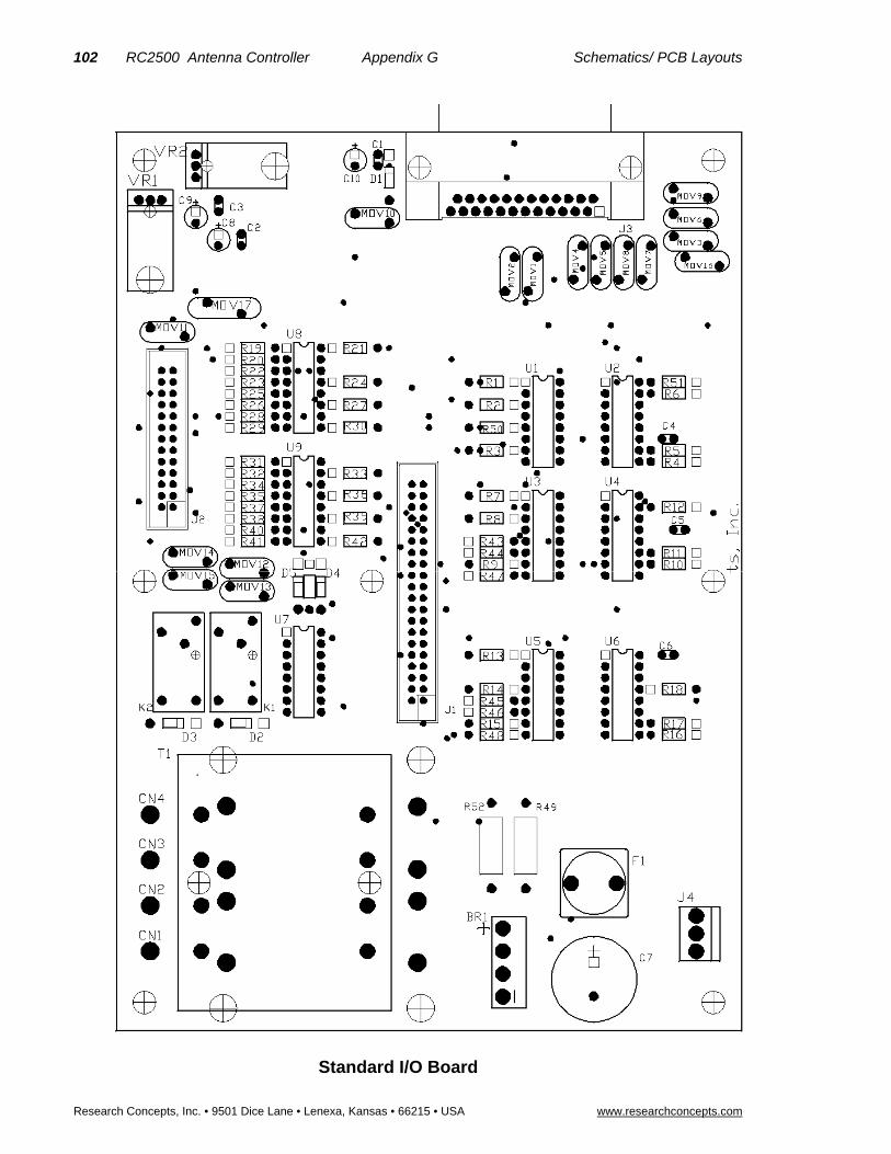
102 RC2500 Antenna Controller Appendix G Schematics/ PCB Layouts
Research Concepts, Inc. • 9501 Dice Lane • Lenexa, Kansas • 66215 • USA www.researchconcepts.com
Standard I/O Board
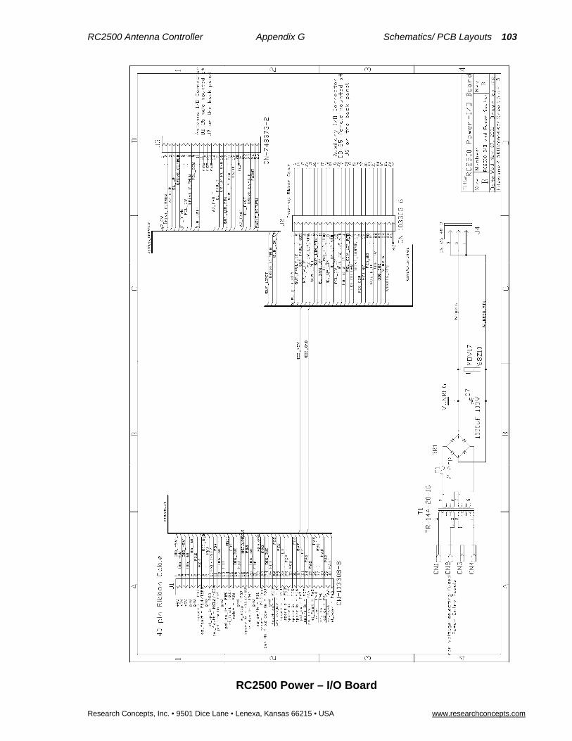
RC2500 Antenna Controller Appendix G Schematics/ PCB Layouts 103
Research Concepts, Inc. • 9501 Dice Lane • Lenexa, Kansas 66215 • USA www.researchconcepts.com
RC2500 Power – I/O Board

104 RC2500 Antenna Controller Appendix G Schematics/ PCB Layouts
Research Concepts, Inc. • 9501 Dice Lane • Lenexa, Kansas • 66215 • USA www.researchconcepts.com
RC2500 I/O & Power Section – Input Section
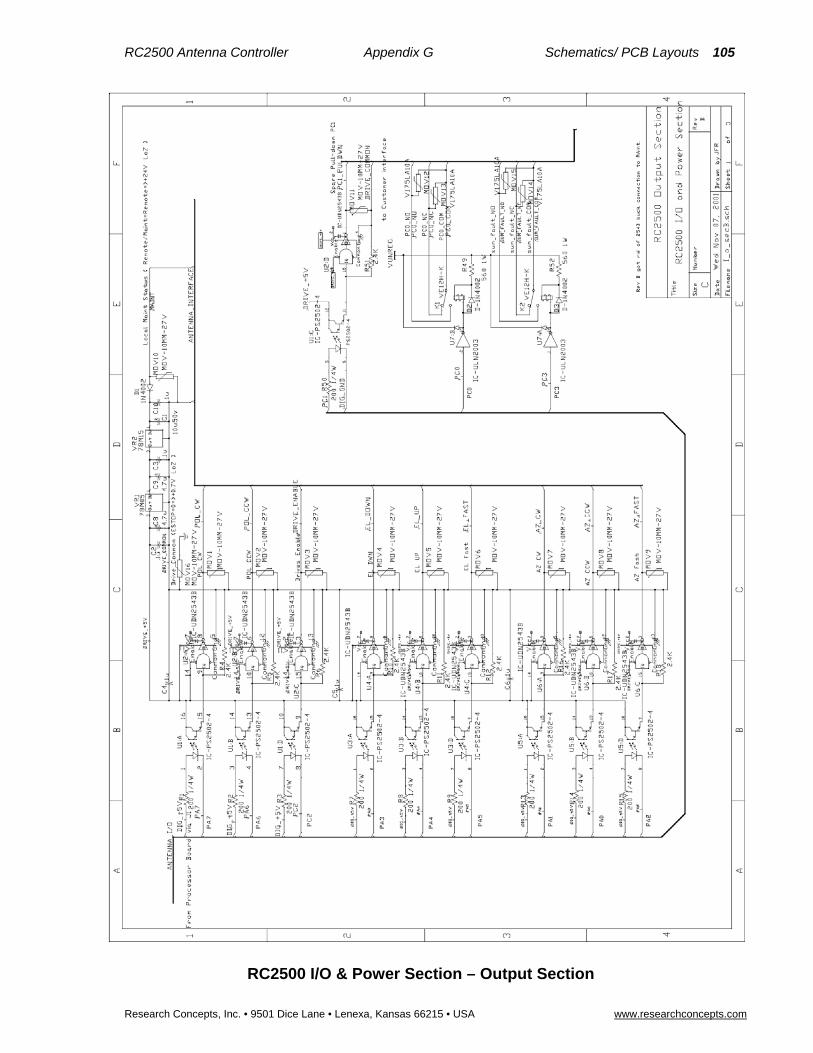
RC2500 Antenna Controller Appendix G Schematics/ PCB Layouts 105
Research Concepts, Inc. • 9501 Dice Lane • Lenexa, Kansas 66215 • USA www.researchconcepts.com
RC2500 I/O & Power Section – Output Section
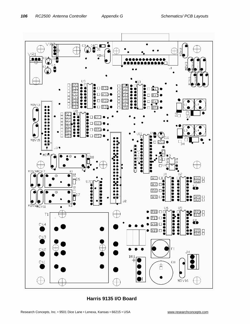
106 RC2500 Antenna Controller Appendix G Schematics/ PCB Layouts
Research Concepts, Inc. • 9501 Dice Lane • Lenexa, Kansas • 66215 • USA www.researchconcepts.com
Harris 9135 I/O Board
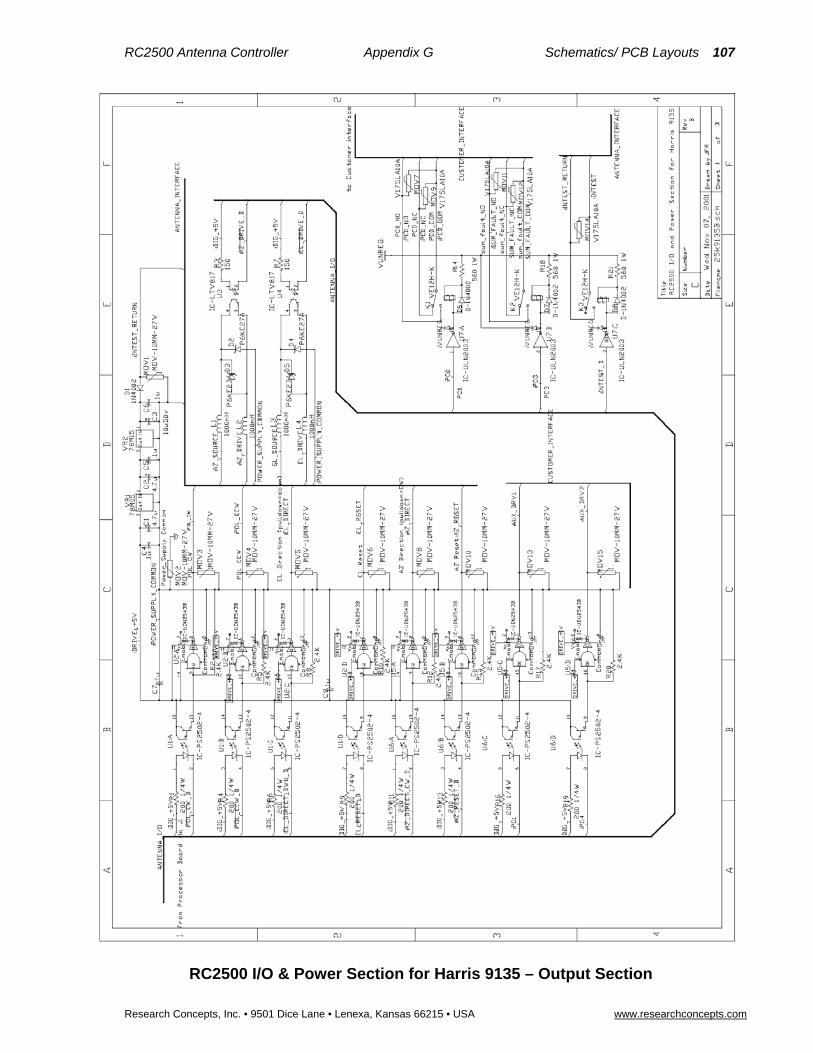
RC2500 Antenna Controller Appendix G Schematics/ PCB Layouts 107
Research Concepts, Inc. • 9501 Dice Lane • Lenexa, Kansas 66215 • USA www.researchconcepts.com
RC2500 I/O & Power Section for Harris 9135 – Output Section

108 RC2500 Antenna Controller Appendix G Schematics/ PCB Layouts
Research Concepts, Inc. • 9501 Dice Lane • Lenexa, Kansas • 66215 • USA www.researchconcepts.com
RC2500 I/O & Power Section for Harris 9135 – Input Section

RC2500 Antenna Controller Appendix H Polarization Sensing with a Potentiometer 109
Research Concepts, Inc. • 9501 Dice Lane • Lenexa, Kansas 66215 • USA www.researchconcepts.com
Appendix H – Polarization Sensing with a Potentiometer
General Description The RC2500 v1.07 software release supports a potentiometer based polarization position sensor. Versions of the software that support this feature can be identified by examining the five character string that immediately follows the software version number on the controller’s startup screen. The five character will consist of lower case letters and the hyphen character (‘-‘). The fifth character in that string will be ‘p‘ for versions of the software that support a potentiometer based polarization sensor or a hyphen for versions of the software that are configured for the usual resolver based sensor.
The polarization potentiometer is interfaced to the controller via a small printed circuit board that attaches to the controller’s AGC port. The AGC port is normally used to input analog signal strength information for implementing a step track based inclined orbit satellite tracking algorithm. When the software that supports a polarization potentiometer is installed the controller’s AGC1 input is connected to the polarization sense potentiometer. Note that the controller’s AGC2 input is still supported when the controller is configured for use with a polarization potentiometer. The cables that interface to the polarization potentiometer and the AGC2 signal source terminate on a connector on the circuit board that is attached to the controller’s AGC port.
The printed circuit board that is used as the interface between the AGC port and the polarization sensor is RCI p/n FC-2_5KPLP2. The Layout and Schematic of this PCB is shown at the end of this section. When used with FC-2_5KPLP2, the RC2500 AGC1 channel is disabled and wired for a direct pass-through of the 0 to 5V polarization pot signal. Referring to schematic of the RC2500 digital board (appendix G), pots P3 and P4 were removed. Resistor R16 was replaced with a 20K resistor. The wiper of pot P4 was jumpered to the CW terminal of P4. The wiper of pot P3 was jumpered to the CCW terminal of P4. An additional 20K resistor was added to ground from pin 3 of U17:B.
The Polarization potentiometer connections are made to the terminal strip on the 2_5KPLP2 PCB. The pot terminal closest in resistance to the pot wiper when the Pol axis is fully CCW should be connected to the “Ref” terminal. The wiper of the pot should be connected to the “Signal” terminal. And the remaining terminal of the pot should be connected to the return terminal.
Software that supports the potentiometer based polarization sensor includes an additional CONFIG mode item to allow for the display of polarization position in an angular format. The CONFIG mode item is designated Pol Display Scale Factor and it specifies the number of degrees of polarization movement per for each one volt change in the polarization position sense voltage.
POL DISPLAY SCALE FACTOR: 20 CONFIG DEG/VOLT, 5 – 500 ENT,BKSP,SCRLL ^v
To sense the polarization position the controller applies a 5 volt DC reference voltage to the potentiometer via the interface board’s Ref and RTN terminals. As the potentiometer shaft is rotated the voltage on the pot’s wiper terminal (connected to the interface board’s Sig terminal) varies between the voltages applied to the pot’s other two terminals. The controller’s microprocessor reads this voltage as a numeric value between 0 and 1023 (1023 = 210-1).
The controller’s displayed polarization position is calculated according to the following formula …
Pol_Position = ((5 * Pol_Cnt * Scale_Factor) / 1024) + Offset (Equation 1)
Where …
Pol_Position is the polarization angle in degrees.tenths_of_degrees
Pol_Cnt is the potentiometer wiper voltage converted to a numeric value 0 to 1023 for a 0.0 to 5.0 volt input.
Scale_Factor is the Pol Display Scale Factor CONFIG mode item described above.
Offset is the Pol Display Offset CONFIG mode item described in the RC2500 User Manual.

110 RC2500 Antenna Controller Appendix H Polarization Sensing with a Potentiometer
Research Concepts, Inc. • 9501 Dice Lane • Lenexa, Kansas • 66215 • USA www.researchconcepts.com
FC-2_5KPLP2 – Layout

RC2500 Antenna Controller Appendix H Polarization Sensing with a Potentiometer 111
Research Concepts, Inc. • 9501 Dice Lane • Lenexa, Kansas 66215 • USA www.researchconcepts.com
FC-2_5KPLP2 – Schematic

112 RC2500 Antenna Controller Appendix H Polarization Sensing with a Potentiometer
Research Concepts, Inc. • 9501 Dice Lane • Lenexa, Kansas • 66215 • USA www.researchconcepts.com
Configuring Controller to Display Polarization Angle
To interface the controller to the polarization position sense potentiometer and calibrate the controller to display the polarization in an angular format, use the following procedure …
1. Power down the controller. Ensure that the potentiometer will not encounter an internal physical limit before the feed’s physical limit of rotation is reached or the polarization limit switch becomes active. This is sometimes referred to as ‘centering the pot’. An ohm meter may be useful here.
2. Connect the potentiometer to the controller using the interface diagram. It is best to use shielded cable with a bare drain wire. Connect the pot’s wiper to the Sig terminal of the interface board. Make the other two pot connections to the Ref and RTN terminals of the interface board. Connect the drain wire at the back of the interface board’s RTN (return) terminal. The drain wire should not be connected to anything at the antenna nor should the drain wire or shield be allowed to come in contact with earth ground (or any metal connected to earth ground - like the antenna mount). If the cable is spliced be sure to splice the drain wire. By not allowing the shield or drain wire to come in contact with earth ground ground loops will be avoided. Ground loops can lead to noise pickup and unreliable polarization position readings.
3. Connect the polarization motor drive lines.
4. Power up the controller. Make sure that the Pol Display Offset and Reverse Pol Sensor Direction CONFIG mode items are set to zero.
5. From MANUAL mode, jog the controller in polarization using the Pol CW and Pol CCW keys. When the Pol CW key is jogged the displayed polarization position must increase. Note that if the pol jog keys are depressed and the controller does not sense antenna movement or if the movement is in the wrong direction a Pol Alarm message will flash on the bottom row of the controller’s LCD display. The jog keys must be depressed for at least two seconds before the alarm will be sensed. This alarm can be reset by either using the controller’s RESET mode or by cycling power to the controller. If the movement is in the wrong direction either reverse the wires connected to the Ref and RTN terminals, reverse the motor’s direction of rotation by reconfiguring the motor drive line, or use the Reverse Pol Sensor Direction CONFIG mode item.
6. The reference position for polarization position angle display is usually vertical polarization of a satellite located at a longitudinal position equal to that of the earth station. Note that for C band satellites the polarization orientation of adjacent satellites are well coordinated. For Ku band satellites this is often not the case. Align the antenna with a satellite and peak up vertical polarization on that satellite. Use a volt meter to measure the voltage between the interface board’s Sig and RTN terminals. Record this voltage along with the satellite longitude position. Call this SAT1.
7. Repeat step 6 for a different satellite. Call this SAT2.
8. Use the following relationship to calculate the satellite polarization angle … Pol_Angle = - ATAN( sin(L) / tan(A) ) (Equation 2) where L is the difference in longitude between the satellite and earth station, and A is the earth station latitude. All angles are in degrees. Treat westerly longitudes as negative numbers. The sign of L is important.
9. Calculate the ratio … R = (Pol_Angle_SAT1 – Pol_Angle_SAT2) / (Pol_Voltage_SAT1 – Pol_Voltage_SAT2) (Equation 3) If R is a negative number change the sign to make it a positive number. Round to the nearest integer value and enter the value into the controller as the Pol Display Scale Factor CONFIG mode item.
10. Go to the controller’s MANUAL mode. With the antenna aligned with SAT2 and peaked on vertical polarization note the displayed polarization angle (designated Disp_SAT2). Calculate the following quantity .. Pol_Display_Offset = Pol_Angle_SAT2 – Disp_SAT2 (Equation 4)

RC2500 Antenna Controller Appendix H Polarization Sensing with a Potentiometer 113
Research Concepts, Inc. • 9501 Dice Lane • Lenexa, Kansas 66215 • USA www.researchconcepts.com
Enter this value into the controller at the Pol Display Offset CONFIG mode prompt. In MANUAL mode the controller should now display a polarization position of Pol_Angle_SAT2.
An Example Assume that the earth station is located at 39 N latitude, 95 W longitude. The antenna is first aligned with Satellite 1 and peaked up on vertical polarization. The voltage between the add-on board’s Sig (+ DVM test lead) and RTN (- DVM test lead) terminals is measured and recorded. The antenna is next aligned with Satellite 2 and peaked on vertical polarization. Again the voltage between the Sig and RTN terminals is recorded.
Satellite 1 Satellite 2
Longitude 99 W (-99) 87 W (-87)
Pol_Voltage 2.75 volts 2.0 volts
L -99 - -95 = -4 -87- -95 = 8
Pol_Angle (use equation 2) 4.9 degrees -9.8 degrees
Calculate the Display Pol Scale Factor CONFIG mode item (equation 3 above) …
(4.9 – (-9.8)) / (2.75 – 2.0) = 14.7 / 0.75 = 19.6 degrees per volt.
Round this to 20 deg/volt and enter this value into the controller via the CONFIG mode Display Pol Scale Factor prompt. Make sure that the Pol Display Offset CONFIG mode item is set to 0.0. Return to the controller’s MANUAL mode.
In MANUAL mode, with the antenna peaked on Satellite 2 vertical polarization and the Pol Display Offset CONFIG mode item set to 0.0, the display should read 40.03 degrees. We know this based on equation 1 and the microprocessor’s A/D characteristic – a value of 0 to 5 volts is converted into a numeric value of 0 to 1023. For this example, 2.0 volts * 1024 / 5.0 is approximately 410 position counts.
In the table above the Pol_Angle for SAT2 is given as –9.8 degrees. The displayed polarization of 40.03 degrees corresponds to the Disp_Sat2 value referenced in step 10 above. Calculate the value of the Pol Display Offset CONFIG mode item (equation 4 above) ….
Pol_Display_Offset = -9.8 – 40.03 = -49.83
Enter this value at the Pol Display Offset CONFIG mode prompt. In MANUAL mode the displayed polarization position should now be –9.8.

114 RC2500 Antenna Controller Appendix I Replacing the SA 8840 Controller
Research Concepts, Inc. • 9501 Dice Lane • Lenexa, Kansas • 66215 • USA www.researchconcepts.com
Appendix I – Replacing the SA 8840 Controller It is possible to use the RC2500 to replace the Scientific Atlanta SA8840A Antenna Controller and enjoy the added capabilities of inclined-orbit tracking and PC remote control. In order to be compatible with the Antenna and SA8841A outdoor box, resolvers are placed on the azimuth and elevation pivot points, a potentiometer is installed to sense polarization position (See Appendix H above), and several RC2500 modifications both hardware and software are performed at the factory. The firmware version for this unit is: version 1.07wsa-p, the date: 2.19.98, and the checksum: 'A1'.
The SA8841A outdoor box reports Limits to the indoor box with open-collector drivers. Six inputs transfer limit information to the RC2500. They are: AZ_CW, AZ_CCW, EL_UP, EL_DWN, POL_CW, POL_CCW. The “safe” operating region is defined as the non- conducting state of the drivers. That is a low-voltage (on the order of 0.4V) on the RC2500 input terminal indicates a limit has been reached. A high voltage (+24VDC) on the pin indicates that a limit has not been reached. Note that this is different from other control schemes where the conducting state indicates the safe operating region.
A seventh input, Pedestal_Override, lets the RC2500 know whether the antenna is being jogged under local control at the base-mounted SA8841 A.I.U. Again, this is an open-collector driver. When Pedestal override is active, this driver is non-conducting, the input voltage on the pin would be high (+24VDC), and the RC2500 will indicate “MAINTENANCE” flashing on the lower line of the display.
The drive board of the RC2500, FC-2_5K9135, is modified to accept a “low-side” limit switch input. The following components are removed: MOV1, MOV2, L1, L2, L3, L4, D2, D3, D4, D5, U3, U4, R3, R7, K3, D8, R21, and MOV14. Referring to the schematic of the AZ-CCW_LIM input section of the board on page 101 (Appendix G), resistors R40 and R42 were removed. A single 2K resistor is inserted vertically into the pad of R40 connected to U10 pin 1. The free end of this resistor is tied via a flying lead to the +24VDC unregulated supply found at the R21 high-side pad. A jumper is added from the R42 pad connected to U10 pin 2 to the remaining free pad of R40. Similar modifications are made for the 6 remaining limit input circuits. The Aux relay drive input line are jumpered to free PLD outputs. The table below indicates which RC2500 input connection is used for each outdoor box limit connection.
SA8840A limit signal RC2500 input pin
AZ Limit Up (CW) Antenna I/O connector J7 Pin 1
AZ Limit Down (CCW) Antenna I/O connector J7 Pin 16
EL Limit Up Antenna I/O connector J7 Pin 15
EL Limit Down Antenna I/O connector J7 Pin 3
POL Limit Up (CW) Antenna I/O connector J7 Pin 2
POL Limit Down (CCW) Antenna I/O connector J7 Pin 14
Pedestal Override Antenna I/O connector J7 Pin 4
There are four other connections that must be made to disable limit inputs of the RC2500:
RC2500 J7 pin Disposition for SA8840 version
J7-5 AZ_Fault Externally jumpered to J7-10 to disable AZ_Fault
J7-18 EL_Fault Externally jumpered to J7-23 to disable EL_Fault
J6-12 Intest Externally jumpered to J6-7 (+24VDC supply line)
J6-24 pwr_supply_common Externally jumpered to J6-21 (+24VDC return line)
The Output of the RC2500 with its 700mA open-collector drivers is directly compatible with the drive inputs to the outdoor box. The definition of the pins have been changed from that in the original 9135
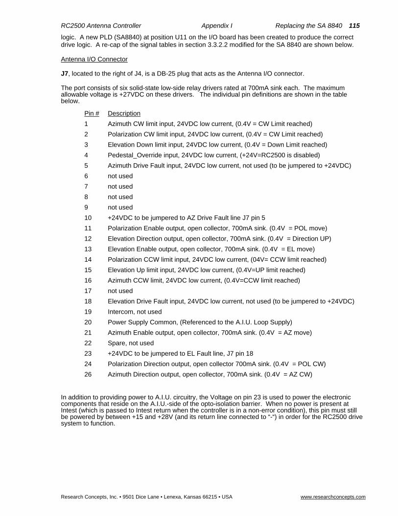
RC2500 Antenna Controller Appendix I Replacing the SA 8840 115
Research Concepts, Inc. • 9501 Dice Lane • Lenexa, Kansas 66215 • USA www.researchconcepts.com
logic. A new PLD (SA8840) at position U11 on the I/O board has been created to produce the correct drive logic. A re-cap of the signal tables in section 3.3.2.2 modified for the SA 8840 are shown below.
Antenna I/O Connector
J7, located to the right of J4, is a DB-25 plug that acts as the Antenna I/O connector.
The port consists of six solid-state low-side relay drivers rated at 700mA sink each. The maximum allowable voltage is +27VDC on these drivers. The individual pin definitions are shown in the table below.
Pin # Description
1 Azimuth CW limit input, 24VDC low current, (0.4V = CW Limit reached)
2 Polarization CW limit input, 24VDC low current, (0.4V = CW Limit reached)
3 Elevation Down limit input, 24VDC low current, (0.4V = Down Limit reached)
4 Pedestal_Override input, 24VDC low current, (+24V=RC2500 is disabled)
5 Azimuth Drive Fault input, 24VDC low current, not used (to be jumpered to +24VDC)
6 not used
7 not used
8 not used
9 not used
10 +24VDC to be jumpered to AZ Drive Fault line J7 pin 5
11 Polarization Enable output, open collector, 700mA sink. (0.4V = POL move)
12 Elevation Direction output, open collector, 700mA sink. (0.4V = Direction UP)
13 Elevation Enable output, open collector, 700mA sink. (0.4V = EL move)
14 Polarization CCW limit input, 24VDC low current, (04V= CCW limit reached)
15 Elevation Up limit input, 24VDC low current, (0.4V=UP limit reached)
16 Azimuth CCW limit, 24VDC low current, (0.4V=CCW limit reached)
17 not used
18 Elevation Drive Fault input, 24VDC low current, not used (to be jumpered to +24VDC)
19 Intercom, not used
20 Power Supply Common, (Referenced to the A.I.U. Loop Supply)
21 Azimuth Enable output, open collector, 700mA sink. (0.4V = AZ move)
22 Spare, not used
23 +24VDC to be jumpered to EL Fault line, J7 pin 18
24 Polarization Direction output, open collector 700mA sink. (0.4V = POL CW)
26 Azimuth Direction output, open collector, 700mA sink. (0.4V = AZ CW)
In addition to providing power to A.I.U. circuitry, the Voltage on pin 23 is used to power the electronic components that reside on the A.I.U.-side of the opto-isolation barrier. When no power is present at Intest (which is passed to Intest return when the controller is in a non-error condition), this pin must still be powered by between +15 and +28V (and its return line connected to “-“) in order for the RC2500 drive system to function.

116 RC2500 Antenna Controller Appendix I Replacing the SA 8840 Controller
Research Concepts, Inc. • 9501 Dice Lane • Lenexa, Kansas • 66215 • USA www.researchconcepts.com
Auxiliary I/O Connection
J6, located directly above J7, is the Auxiliary I/O connector. This port, based on a DB-25 receptacle, supports a single isolated input, contact closures for summary faults and peripheral equipment control as well as two open collector relay drivers similar to those found in J7. The INTEST, INTEST Return and Power Supply Common connections of J6 are duplicated here for convenience. A +24 VDC unregulated output (1 Amp max) referenced to the RC2500 ground is also available. The individual pin definitions are shown in the table below.
Pin # Description
1 Summary Fault dry contact COM, (3A @ 125VAC or 3A @ 30VDC).
3 Summary Fault dry contact NO, (3A @ 125VAC or 3A @ 30VDC).
3 PC0 dry contact COM, (3A @ 125VAC or 3A @ 30VDC).
4 PC0 dry contact NC, (3A @ 125VAC or 3A @ 30VDC).
5 PC0 dry contact NO, (3A @ 125VAC or 3A @ 30VDC).
6 Unregulated +24 VDC bus voltage, 1 Amp max.
7 Unregulated +24 VDC bus voltage, 1 Amp max. externally jumpered to J6 pin 12.
8 AZ Speed, open collector relay driver, 700mA sink, (0.4V = AZ slow)
9 EL Speed, open collector relay driver, 700mA sink, (0.4V = EL slow)
10 INTEST (see J7 pin 10), 24VDC high current from A.I.U.
11 INTEST (see J7 pin 10), 24VDC high current from A.I.U.
12 INTEST Return (see J7 pin 23), externally jumpered to J6 pin 7.
13 INTEST Return (see J7 pin 23),
14 Summary Fault dry contact NC, (3A @ 125VAC or 3A @ 30VDC).
15 Unregulated +24 VDC return, (RC2500 ground)
16 Unregulated +24 VDC return, (RC2500 ground)
17 Unregulated +24 VDC return, (RC2500 ground)
18 Unregulated +24 VDC return, (RC2500 ground)
19 Unregulated +24 VDC return, (RC2500 ground)
20 Unregulated +24 VDC return, (RC2500 ground)
21 Unregulated +24 VDC return, (RC2500 ground), externally jumpered to J6 pin 24
22 Auxiliary Input 1, 24VDC low current.
23 Auxiliary Input 1 Return, 24VDC low current.
24 Power Supply Common, externally jumpered to J6 pin 21
25 Power Supply Common, (Referenced to the A.I.U. Loop Supply)
A 24” adapter cable has been produced ( RCI p/n FB-SA8840DONGL) that makes the interconnection between the RC2500 and connectors that previously went to the SA8840 ACU. The Schematic of this Dongle is supplied on the following page.

RC2500 Antenna Controller Appendix I Replacing the SA 8840 117
Research Concepts, Inc. • 9501 Dice Lane • Lenexa, Kansas 66215 • USA www.researchconcepts.com
FB-SA8840DONGL

118 RC2500 Antenna Controller Appendix J Replacing the RSI/Satcom 4010 Controller
Research Concepts, Inc. • 9501 Dice Lane • Lenexa, Kansas • 66215 • USA www.researchconcepts.com
Appendix J – Replacing the RSI/ Satcom 4010 Controller It is possible to use the RC2500 to replace the RSI/ Satcom Technologies 4010 Antenna Controller and enjoy the added capabilities of inclined-orbit tracking and PC remote control. In order to be compatible with the Antenna and 4020 outdoor box, resolvers are placed on the azimuth and elevation pivot points, a potentiometer is installed to sense polarization position (See Appendix H above), and several RC2500 modifications both hardware and software are performed at the factory. The firmware version for this unit is: version 1.07wra-p, the date: 3.17.98, and the checksum: '34'.
The 4020 has 5VDC isolated limit switch outputs that are directly compatible with the inputs of the RC2500 using the Standard I/O board with isolated inputs (7134 version). The limit “+” terminal of the 4020 is connected to the limit input and the limit “-“ terminal of the 4020 is connected to the limit return line. The “safe” operating region is defined as the non- conducting state of the drivers. That is a pull-down occurring on the limit return line (5VDC is always on the limit input) of the RC2500 input terminal indicates a limit has been reached. A high voltage (+5VDC) on the limit return line indicates that a limit has not been reached. Note that this is different from other control schemes where the conducting state indicates the safe operating region. A software modification has been performed to compensate for the inversion. All six positional limits operate in this manner.
A seventh input, Auto/Man, lets the RC2500 know whether the antenna is being jogged under local control at the base-mounted 4020 A.I.U. Again, this is a pull-down on the Maintenance Status Return line with +5VDC always on the Maintenance Status Input line. When Manual Mode (RC2500 to be disabled) is active, this driver is non-conducting, the voltage on the maintenance status return line would be high (+5VDC), and the RC2500 will indicate “MAINTENANCE” flashing on the lower line of the display.
The Standard pin-out information found in section 3.3.2.1 is applicable for this version with the exceptions described below. In order for the Internal drive system to function, the Maintenance input of the RC2500 must be powered by a voltage between 17 and 24 VDC. A jumper is connected externally from J6 pin 25 to J7 pin 24 to facilitate this. This circuit is completed by using an external jumper to connect the Drive Common line to Vunreg return. (J7 pin 8 to J6 pin13). The ESTOP circuit was disabled by wiring The ESTOP input to Vunreg (+24VDC) and the ESTOP return line to Vunreg return. (jumper J7 pin 19 to J6 pin 25 and then jumper J7 pin 16 to J6 pin 13). Both Drive fault lines are disabled by connecting U8 pin 12 to U8 pin 11 and connecting U8 pin 13 to U8 pin 14.

RC2500 Antenna Controller Appendix K Driving 36VDC Motors 119
Research Concepts, Inc. • 9501 Dice Lane • Lenexa, Kansas 66215 • USA www.researchconcepts.com
Appendix K – Driving 36VDC Motors Using the Smart Booster II
Single Speed 36 VDC AIU for an Antenna with TVRO-type Actuators
1.0 Scope
An antenna control package has been designed for Rincon Research. The customer has a pair of DH 4.2 meter antennas which utilize an elevation over azimuth type mount equipped with 36 VDC actuators. The customer wants to modify the antenna to allow tracking of non-geosynchronous satellites based on two line element data sets. The customer wants to send antenna steering commands to the antenna controller from a PC.
To allow open loop satellite tracking the antenna needs to be equipped with true sensing position encoders. The antenna controller will be an RC2500 running the Vertex 7134 outdoor unit software. The RC2500 supports resolver type position sensors. For the AIU a pair of modified Research Concepts Smart Booster II drives will be employed – one driving the azimuth axis and the other driving the elevation axis. These are solid state drives with a maximum rated output of 8 amps at about 30 VDC. The drives operate at a single speed and support dynamic braking and electronic over-current protection.
It is assumed that the antenna will use either the existing limit switches or will be equipped with limit switches based on steering diodes. The modifications do not address polarization control.
This document describes the RC2500 interface to the AIU and the modifications performed to the Smart Booster II product.
2.0 Smart Booster
The Smart Booster II is a 36 volt DC drive designed to allow satellite receivers with low current actuator drives to control large satellite antennas equipped with 36 volt actuators. The Smart Booster II can supply up to 8 amps (at 30 volts) to the actuators. The drive utilizes a single solid state H bridge with built-in electronic overcurrent sensing and dynamic braking.
The Smart Booster II supports dual axis mounts – both axis can not be driven simultaneously, however. A DPDT relay connects the H bridge to either the azimuth or elevation axis actuators. The input circuit for each axis consists of a pair of opto-isolators. For a given axis, a pair of terminals connects the input circuit to the low current actuator drive of a satellite receiver. When the Smart Booster detects current flow it activates the H bridge and configures the DPDT relay if necessary. The polarity of the output current is determined by the polarity of the input current.
For this application the following modifications are performed to the Smart Booster II …
The input circuits are modified to interface to the RC2500 control outputs. The RC2500 employs pull down current drivers. The Booster is modified to accept a 24 volt DC loop power supply voltage (available from the RC2500) as well as 3 pull down inputs to interface to the RC2500 AZ CW (EL UP), AZ CCW (EL DOWN), and DRIVE ENABLE outputs. The DRIVE ENABLE output is used to reset a drive alarm condition (caused by an over-current).
The DPDT relay is disabled to remove support for two axis control.
One of the motor drive terminals for the disabled axis is used to indicate drive alarm status.

120 RC2500 Antenna Controller Appendix K Driving 36VDC Motors
Research Concepts, Inc. • 9501 Dice Lane • Lenexa, Kansas • 66215 • USA www.researchconcepts.com
2.1 Smart Booster Modifications
Remove the following components: R32, C3, C4, V1, V2
Replace the following components …
Component Replace With …
R5 Jumper
R6, R7, R8 2600 ohm, 1 watt resistor. Alternatively, a second 1300 ohm, 0.5 watt resister can be added in series with the existing 1300 ohm, 0.5 watt resister.
U6 (PLD – programmable logic device)
Replace the standard PLD (BOOST4) with the BOOST5 PLD.
Install the following components …
Component Description
D12 1N4002
K3 G6H-2-12VDC relay (10 pin DIP). Use a 14 pin socket with 4 pins removed.
R31 2000 ohm, ¼ watt resistor
Make the following modifications to the board (see the circuit board bottom trace mask) …
1. Near IC3, cut two traces and install two jumpers.
2. Install a 1300 ohm, 0.5 watt resistor between J2-5 and J3-4. Use heat shrink tubing to prevent shorts.
3. Install a 16 AWG jumper between J3-2 and the large via in the trace connected to J2-2.
2.2 Smart Booster I/O
The following table describes the input and output characteristics of the modified Smart Booster.
J2 Terminal Description
J2-1 No Connect
J2-2 Alarm Status Output, 24 VDC => No Alarm, Float => Over-current Alarm Active
J2-3 Motor Drive Output
J2-4 Motor Drive Output
J2-5 24 VDC Input
J2-6 Az Ccw/El Down Input. Pull to ground to activate drive. Internally tied to 24 VDC through 2600 ohm in series with an opto-coupler photo diode.
J2-7 Az Cw/El Up Input. . Pull to ground to activate drive. Internally tied to 24 VDC through 2600 ohm in series with an

RC2500 Antenna Controller Appendix K Driving 36VDC Motors 121
Research Concepts, Inc. • 9501 Dice Lane • Lenexa, Kansas 66215 • USA www.researchconcepts.com
J2 Terminal Description
opto-coupler photo diode.
J2-8 Reset Input. Pull to ground to reset an alarm triggered by an over-current condition. . Internally tied to 24 VDC through 2600 ohm in series with an opto-coupler photo diode.
2.3 Smart Booster Documentation
The following Smart Booster II documents can be found at the end of this section.
Production Smart Booster II Schematic
Schematic Showing Changes to the Smart Booster II input circuit.
PCB Layout with Component Legend
Circuit Board bottom side trace diagram showing cut traces and jumper locations.
Data sheet showing the internal configuration of the Omron G6H type relay (K3 in the Smart Booster).
3.0 RC2500 Interface to the AIU
This section describes the interface of the RC2500 (running Vertex 7134 AIU software) to the Smart Booster based AIU. This version of the RC2500 supports a number of features that are not needed for this application.
All controller output signals are optically isolated pull down type current drivers. There are a number of terminals dedicated to the return signals associated with these pull down drivers. The controller’s unregulated 24 volts DC power supply and the associated return are available on the Auxiliary I/O connector (J6). This voltage will be used to power the control loop (i.e. provide current for the pull down drivers).
The controller inputs are optically isolated. A current of approximately 1 milliamp (ma) will ‘turn the input on’. Note that each input has a return associated with it. A given return may be connected to a number of ‘inputs’.
Note that the documentation for the RC2500 states that J6 is the Antenna I/O connector and J7 is the Auxiliary I/O connector. The labeling on the back of the controller lists J7 as the Antenna I/O connector and J6 as the Auxiliary I/O connector. The back panel is correct.
Here is a description of the signals present on the controller’s J7 connector (D25 male) …
Terminal Signal Name Description
1, 3, 4, 6, 7, 9
AZ CW, AZ CCW, EL UP, EL DOWN, POL CW, POL CCW respectively.
Pull down type current drivers. The controller turns the driver ON to command the antenna to move in the direction associated with the driver.
2, 5, 8 DRIVE COMMON The return paths associated with the az, el, and pol drivers. Note that this signal is also available on the controller’s Auxiliary I/O connector (J6).
10 SUMMARY LIMIT Summary Limit input. When the current to this terminal is interrupted the controller assumes that one of the limit switches is active. Not used with the 36 volt AIU. Tied to 24 VDC in this design. Note that this signal is also present on the Auxiliary I/O connector (J6). When this input is asserted the controller displays the ‘Summary Limit’ alarm message.
11, 12, 13 NO CONNECTS In this design these pins should be tied to the SUMMARY LIMIT (24 VDC) via bus wire on the J7 mating connector. Other circuits that require 24 VDC are tied to these terminals

122 RC2500 Antenna Controller Appendix K Driving 36VDC Motors
Research Concepts, Inc. • 9501 Dice Lane • Lenexa, Kansas • 66215 • USA www.researchconcepts.com
Terminal Signal Name Description
on the J7 mating terminal.
14, 15 AZ DRIVE FAULT, EL DRIVE FAULT
These inputs indicate the fault status of the azimuth and elevation drives. When current flows into these inputs the controller assumes that the drives are OK. The input current associated with these inputs returns via the SUMMARY LIMIT RETURN. In this design these inputs are connected to the Alarm Status outputs of the azimuth and elevation drives.
16 ESTOP RETURN This is the return associated with the emergency stop input. In this design this pin is tied to one of the SUMMARY LIMIT RETURN terminals (which is at ground potential) via bus wire on the J7 mating connector.
17, 18 SUMMARY LIMIT RETURN
The return associated with the SUMMARY LIMIT input. Tied to ground in this design. Note that this signal is also present on the Auxiliary I/O connector (J6).
19 ESTOP Emergency stop switch input. When current flows into this terminal the controller assumes that the AIU Emergency Stop is not active. If the controller senses that the Emergency Stop is active the controller disables antenna control and displays the ‘Emergency Stop’ message. Not used in this design. This terminal is tied to 24 VDC.
20 Not Connected In this design this terminal is tied to pin 19 via bus wire on the J7 mating connector. Pin 19 is tied to 24 VDC. This terminal is used to connect other circuits to 24 VDC.
21, 22 AZ FAST, EL FAST Azimuth and elevation fast/slow current drivers – not used in this design.
23 DRIVE ENABLE This output is used to reset the azimuth and elevation drives. The controller pulls this pin low to reset the drives. The return associated with this current driver is DRIVE COMMON. On this design this output is connected to the drive Reset In inputs.
24 MAINT Maintenance input. When current flows in this circuit the controller assumes that the AIU is able to accept drive commands from the controller. If current is not flowing in this circuit the controller disables antenna control and displays the ‘Maintenance’ alarm message. In this design this feature is not used and this terminal is tied to 24 VDC.
25 MAINT RETURN The return associated with the MAINT input.
The following table discusses the signals on the RC2500’s Auxiliary I/O connector (J6) …
Terminal Signal Name Description
4 AZ CCW LIMIT RETURN This terminal is internally connected to the SUMMARY LIMIT RETURN signal of the Antenna I/O connector (J7). In this design this terminal is tied to ground to provide a ground return for circuits whose terminals are on the J7 connector.
5, 6, 7, 8 EL DOWN LIMIT RETURN, EL UP LIMIT RETURN, POL CW LIMIT RETURN, POL CCW LIMIT RETURN
These pins are the return signals associated with various limit inputs found on the J6 connector. The circuits are not supported with the RC2500 Vertex 7134 AIU interface software. In this design these terminals are tied with bus wire to the AZ CCW LIMIT RETURN and the DRIVE COMMON terminals only to facilitate connecting those two terminals together.
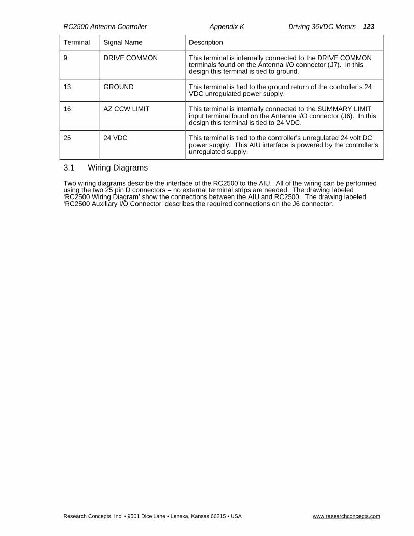
RC2500 Antenna Controller Appendix K Driving 36VDC Motors 123
Research Concepts, Inc. • 9501 Dice Lane • Lenexa, Kansas 66215 • USA www.researchconcepts.com
Terminal Signal Name Description
9 DRIVE COMMON This terminal is internally connected to the DRIVE COMMON terminals found on the Antenna I/O connector (J7). In this design this terminal is tied to ground.
13 GROUND This terminal is tied to the ground return of the controller’s 24 VDC unregulated power supply.
16 AZ CCW LIMIT This terminal is internally connected to the SUMMARY LIMIT input terminal found on the Antenna I/O connector (J6). In this design this terminal is tied to 24 VDC.
25 24 VDC This terminal is tied to the controller’s unregulated 24 volt DC power supply. This AIU interface is powered by the controller’s unregulated supply.
3.1 Wiring Diagrams
Two wiring diagrams describe the interface of the RC2500 to the AIU. All of the wiring can be performed using the two 25 pin D connectors – no external terminal strips are needed. The drawing labeled ‘RC2500 Wiring Diagram’ show the connections between the AIU and RC2500. The drawing labeled ‘RC2500 Auxiliary I/O Connector’ describes the required connections on the J6 connector.

124 RC2500 Antenna Controller Appendix K Driving 36VDC Motors
Research Concepts, Inc. • 9501 Dice Lane • Lenexa, Kansas • 66215 • USA www.researchconcepts.com
Smart Booster II Schematic

RC2500 Antenna Controller Appendix K Driving 36VDC Motors 125
Research Concepts, Inc. • 9501 Dice Lane • Lenexa, Kansas 66215 • USA www.researchconcepts.com
Schematic Showing Changes to the Smart Booster II Input Circuit
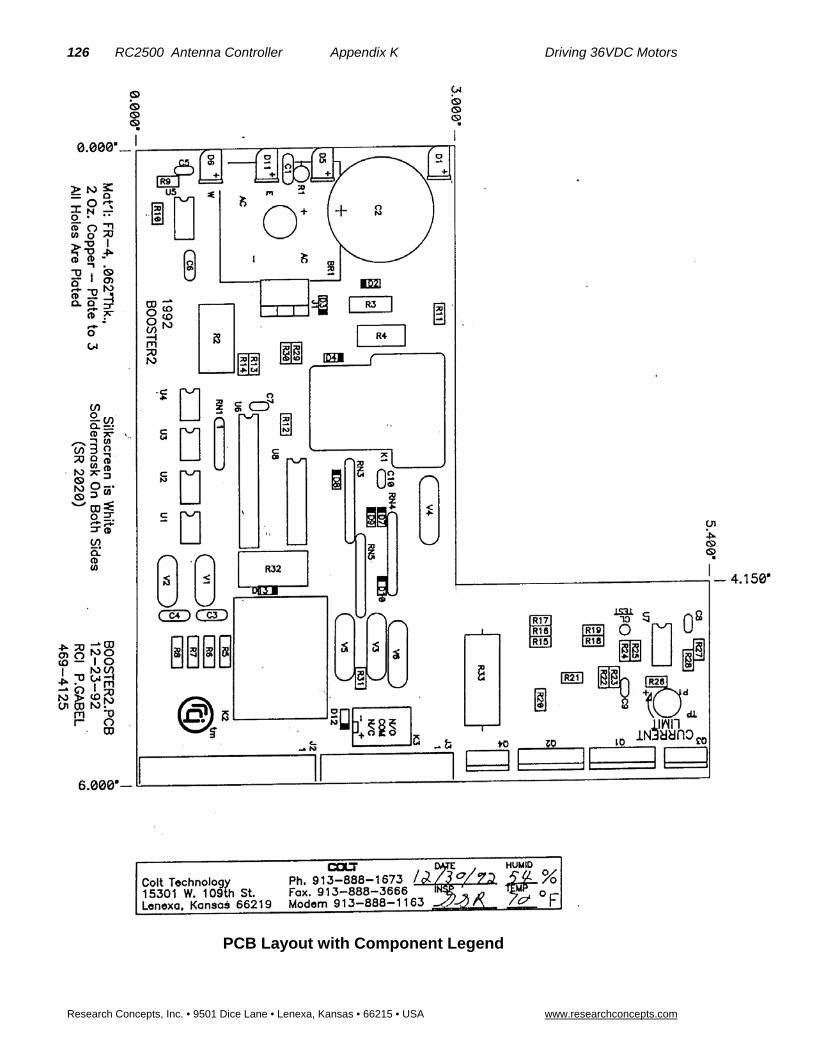
126 RC2500 Antenna Controller Appendix K Driving 36VDC Motors
Research Concepts, Inc. • 9501 Dice Lane • Lenexa, Kansas • 66215 • USA www.researchconcepts.com
PCB Layout with Component Legend

RC2500 Antenna Controller Appendix K Driving 36VDC Motors 127
Research Concepts, Inc. • 9501 Dice Lane • Lenexa, Kansas 66215 • USA www.researchconcepts.com
Circuit Board bottom side trace diagram showing cut traces and jumper locations

128 RC2500 Antenna Controller Appendix K Driving 36VDC Motors
Research Concepts, Inc. • 9501 Dice Lane • Lenexa, Kansas • 66215 • USA www.researchconcepts.com
Data sheet showing the internal configuration of the Omron G6H type relay
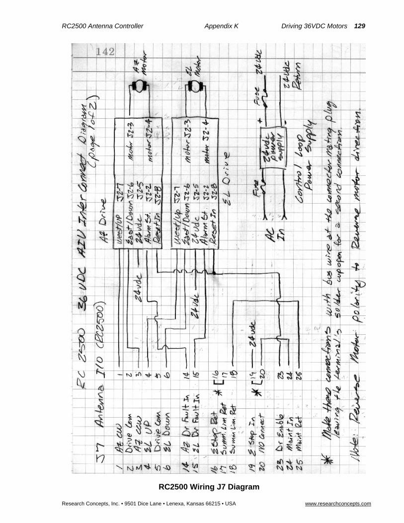
RC2500 Antenna Controller Appendix K Driving 36VDC Motors 129
Research Concepts, Inc. • 9501 Dice Lane • Lenexa, Kansas 66215 • USA www.researchconcepts.com
RC2500 Wiring J7 Diagram
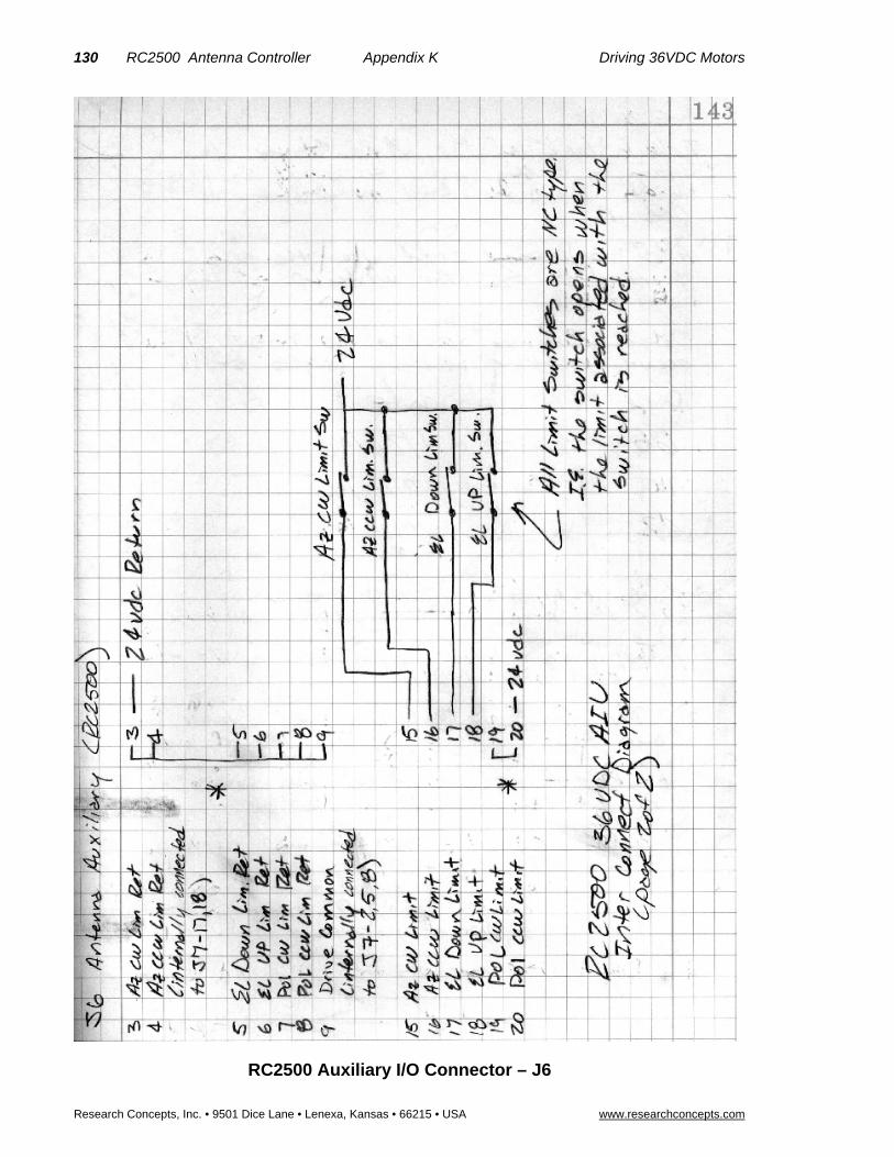
130 RC2500 Antenna Controller Appendix K Driving 36VDC Motors
Research Concepts, Inc. • 9501 Dice Lane • Lenexa, Kansas • 66215 • USA www.researchconcepts.com
RC2500 Auxiliary I/O Connector – J6

RC2500 Antenna Controller Appendix K Driving 36VDC Motors 131
Research Concepts, Inc. • 9501 Dice Lane • Lenexa, Kansas 66215 • USA www.researchconcepts.com
Single Speed 36 VDC AIU for an Antenna with Limit Switches
The following document describes an RC2500 / Smart Booster system for Haystack Observatory. This is similar to the Rincon project – the differences are that the Haystack system will use limit switches on the antenna and the control loop will be powered by an external 24 VDC supply.

132 RC2500 Antenna Controller Appendix L Replacing the Electrospace 93C-23
Research Concepts, Inc. • 9501 Dice Lane • Lenexa, Kansas • 66215 • USA www.researchconcepts.com
Appendix L – Replacing the Electrospace 93C-23 Controller It is possible to use the RC2500 to replace the Electrospace Corporation 93C-23 Antenna Controller and enjoy the added capabilities of inclined-orbit tracking and PC remote control. In order to be compatible with the Antenna and the 83MC4 outdoor box, resolvers are placed on the azimuth and elevation pivot points. If the polarization axis is motorized, a resolver or potentiometer (see appendix H) must be mounted at the polarization pivot point. Information on the connection and use of resolvers is found in section 3.3.1. The firmware version for this unit is: version 1.12eea--, the date: 2.9.00, and the checksum: 'AE'. The RC2500 uses the 2_5KI_O1 as the interface PCB.
Limit and Status Inputs
The 83MC4 has six, 24VDC non-isolated limit switch outputs that are directly compatible with the limit inputs of the RC2500 using the Standard I/O board with isolated inputs. The “Limit Status” terminals of the 83MC4 are connected to the limit input and the limit “Drive Gnd” terminals of the 83MC4 are connected to the limit return lines. The “safe” operating region is defined as the conducting state of the drivers. That is, an open-circuit occurring on the limit status line of the RC2500 input terminal indicates a limit has been reached. All six positional limits operate in this manner.
Three other inputs represent System Interlock, AZ Interlock and EL Interlock. The AZ and EL interlock lines, which, under normal conditions, provide 24VDC, go to an open circuit when the AZ or EL motor circuit breakers trip. These two lines are connected to the AZ Drive fault and EL Drive Fault inputs. When the motor circuit breakers trip, an appropriate drive fault message will be displayed on the RC2500 front panel. To clear these faults, the circuit breakers in the 83MC4 must be switched to the “on” position and then the drive error may be cleared at the RC2500 as described is section 5.6.
The system Interlock provides 24VDC under normal conditions and shows an open circuit when the system interlock is opened or the emergency stop switch is actuated. The system interlock status is connected to the RC2500 Emergency stop input and the Maintenance Status input. Loss of 24V at this point will also cause all position limits to be asserted, AZ and EL Faults, and Emergency Stop will show on the front Panel. After the System Interlock and/or Emergency Stop switches are returned to their normal positions the remaining drive faults may be cleared as described in Section 5.6.
A tenth input, ACU/LOCAL Status, lets the RC2500 know whether the antenna is being jogged under local control at the base-mounted A.I.U. This line is connected to the Maintenance status return line of the RC2500. When Local Mode (RC2500 to be disabled) is activated, by flipping the ACU/LOCAL switch to “LOCAL”, this line is pulled to ground potential and the maintenance optical isolator will go into a conducting state. The RC2500 will indicate “MAINTENANCE” flashing on the lower line of the display until the switch is flipped to “ACU”.
The Output of the RC2500 with its 24V x 700mA open-collector drivers are directly compatible with the drive inputs to the 83MC4 outdoor box. There are 10 drive inputs for the maximum configuration Electrospace AIU. These are: AZ Enable, AZ CW/CCW, AZ Slew, AZ Brake, EL Enable, EL UP/DOWN, EL Slew, EL Brake, POL Enable, and POL CW/CCW.
The Interface between the RC2500 ACU and 83MC4 AIU is summarized in the following tables showing all connections at J6 and J7. There are 13 connections labeled Drive Ground. All of these connections must be connected to the Drive Ground pins of the 83MC4 AIU.
Antenna I/O Connector
J7, located to the right of J4, is a DB-25 plug identified as the Antenna I/O connector. This connector acts as the antenna motion control port of the RC2500. The port consists of 9 solid-state low-side relay drivers rated at 700mA sink each. Max voltage is +27VDC on these drivers. Current is returned to the A.I.U. via the Drive Common line (pins 2,5, and 8). In addition to the drivers, this port supports three 24 VDC, low current, status inputs with isolated returns. The individual pin definitions as well as their mating connection at the 83MC4 are shown in the table below.
RC2500 Pin # & (resource)
Description 83MC4 Pin #

RC2500 Antenna Controller Appendix L Replacing the Electrospace 93C-23 133
Research Concepts, Inc. • 9501 Dice Lane • Lenexa, Kansas 66215 • USA www.researchconcepts.com
RC2500 Pin # & (resource)
Description 83MC4 Pin #
1 (PA1) Azimuth Direction, pull-down drive, 700mA max sink. (0.4V = direction CCW)
AZ CW/CCW TB3-4
2 Drive Ground (return path for AZ, EL, & POL drive command and limit status lines)
DRIVE GND TB3-1,2
3 (PA0) Azimuth Enable, pull-down drive, 700mA max sink. (0.4V = AZ move)
AZ EN TB3-3
4 (PA4) Elevation Enable, pull-down drive, 700mA max sink. (0.4V = EL move)
EL EN TB3-7
5 Drive Ground (return path for AZ, EL, & POL drive command and limit status lines)
DRIVE GND TB3-1,2
6 (PA3) Azimuth Brake, solid state drive, 700mA max sink. (0.4V = AZ Brake release)
AZ BRK TB3-6
7 (PA7) Elevation Brake, solid state drive, 700mA max sink. (0.4V = EL Brake release)
EL BRK TB3-10
8 Drive Ground (return path for AZ, EL, & POL drive command and limit status lines)
DRIVE GND TB3-1,2
9 (PA6) EL Slew, solid state drive, 700mA max sink. (PC1 0.4V = EL Fast Slew)
EL SLEW TB3-??
10 (PB0) Azimuth CCW Limit Status input, 24 VDC low current.(same as J6-16) not used here.
No connect
11 nc
12 nc
13 nc
14 (P2.4) Azimuth Interlock Status input, 24 VDC low current. (0V = AZ fault)
AZ INTLK TB3-17
15 (HSI.1) Elevation Interlock Status input, 24 VDC low current. (0V = EL fault)
EL INTLK TB3-20
16 (PB7) Drive Ground (Emergency Stop status return) DRIVE GND TB3-1,2
17 (PB0, HSI.1, P2.4)
Drive Ground (Interlock Status and Az CCW Lim return; same as J6-4)
DRIVE GND TB3-1,2
18 (PB0, HSI.1, P2.4)
Drive Ground (Interlock Status and Az CCW Lim return; same as J6-4)
DRIVE GND TB3-1,2
19 (PB7) System Interlock Status Input, 24 VDC low current. (ESTOP input, 0V = Emergency STOP)
SYSTEM INTLK TB3-16
20 Nc
21 (PA2) AZ Slew, solid state drive, 700mA max sink. (0.4V = AZ Fast Slew)
AZ SLEW TB3-??
22 (PA5) Elevation Direction, pull-down drive, 700mA max sink. (0.4V = move DOWN)
EL UP/DWN TB3-8
23 (PC2) Polarization Enable, pull-down drive, 700mA max sink. (0.4V = POL move)
POL EN TB3-??
24 (PB6) System Interlock status input, 24 VDC low current. (0V = ESTOP or Interlock open)
SYSTEM INTLK TB3-16
25 (PB6) ACU / Local Status input, low current return path (0V = Local Pedestal controls active.)
ACU/LOCAL STATUS TB3-13
In addition to a Maintenance status indication, the Voltage on pin 24 is used to power the electronic components that reside on the A.I.U.-side of the opto-isolation barrier. When no System Interlock Input is present, this pin must still be powered by between +15 and +28V (and its return line connected to “-“) in order for the RC2500 drive system to function.

134 RC2500 Antenna Controller Appendix L Replacing the Electrospace 93C-23
Research Concepts, Inc. • 9501 Dice Lane • Lenexa, Kansas • 66215 • USA www.researchconcepts.com
Auxiliary I/O Connection
J6, located directly above J7, is the Auxiliary I/O connector. This port, based on a DB-25 receptacle, supports isolated, axis-specific limit inputs as well as contact closures for summary faults and peripheral equipment control. A +5 VDC regulated output (200mA max), a +24 VDC unregulated output (1 Amp max), and an analog voltage input, all referenced to the RC2500 ground, are also available The individual pin definitions are shown in the table below. Both J6 and J7 are required when operating with the Electrospace 83MC4 A.I.U. that support separate limits.
RC2500 Pin # & (resource)
Description 83MC4 Pin #
1 (PC3) Summary Fault dry contact COM, (3A @ 125VAC or 3A @ 30VDC).
Unused
2 (PC3) Summary Fault dry contact NO, (3A @ 125VAC or 3A @ 30VDC).
Unused
3 (PB1) Drive Ground (Azimuth CW Limit return). DRIVE GND TB3-1,2
4 (PB0, HSI.1, P2.4)
Drive Ground (Interlock Status and Az CCW Lim return; same as J7-17)
DRIVE GND TB3-1,2
5 (PB2) Drive Ground (Elevation Down Limit return.) DRIVE GND TB3-1,2
6 (PB3) Drive Ground (Elevation Up Limit return) DRIVE GND TB3-1,2
7 (PB5) Drive Ground (Polarization CW Limit return). DRIVE GND TB3-1,2
8 (PB4) Drive Ground (Polarization CCW Limit return). DRIVE GND TB3-1,2
9 Drive Common (return path, same as J6, pins 2,5,8) DRIVE GND TB3-1,2
10 (PC0) PC0 output dry contact NC, (3A @ 125VAC or 3A @ 30VDC).
Unused
11 (P0.2) P0.2 Auxiliary analog/digital input 0 - +5 VDC. Unused
12 Ground (for digital/analog I/O). Unused
13 Ground for system bus voltages. Unused
14 (PC3) Summary Fault dry contact NC, (3A @ 125VAC or 3A @ 30VDC).
Unused
15 (PB1) Azimuth CW Limit input, 24 VDC low current. (0V = CW Limit reached)
AZ CW Limit Status TB3-19
16 (PB0) Azimuth CCW Limit input, 24VDC (0V = CCW Limit reached) (same as J7-10 ).
AZ CCW Limit Status TB3-18
17 (PB2) Elevation Down Limit input, 24 VDC low current. (0V = Down Limit reached)
EL Down Limit Status TB3-21
18 (PB3) Elevation UP Limit input, 24 VDC low current. (0V = Up Limit reached)
EL Up Limit Status TB3-22
19 (PB5) Polarization CW Limit input, 24 VDC low current. (0V = CW Limit reached)
POL CW Limit Status TB3-??
20 (PB4) Polarization CCW Limit input, 24 VDC low current. (0V = CCW Limit reached)
POL CCW Limit Status TB3-??
21 (PC1) Polarization Direction, pull-down drive, 700mA max sink. (0.4V = move CCW)
POL CW/CCW TB3-??
22 (PC0) PC0 output dry contact COM, (3A @ 125VAC or 3A @ 30VDC).
unused
23 (PC0) PC0 output dry contact NO, (3A @ 125VAC or 3A @ 30VDC).
unused
24 +5 Volts DC digital power, 200mA max. unused
25 Unregulated +24 VDC bus voltage, 1 Amp max.. unused

RC2500 Antenna Controller Appendix L Replacing the Electrospace 93C-23 135
Research Concepts, Inc. • 9501 Dice Lane • Lenexa, Kansas 66215 • USA www.researchconcepts.com
Once the above connections have been made, verify that antenna motion in the appropriate direction can be affected from the front panel in MANUAL mode. You may now continue the RC2500 installation with sections 3.3.3 through 3.5.
Connections to the 83MC4 designated with TB3-?? Indicate that the termination point in the AIU has not been determined at the time of publishing of this appendix. Contact RCI for further support.
136 RC2500 Antenna Controller Appendix M Replacing the Harris 7022
Research Concepts, Inc. • 9501 Dice Lane • Lenexa, Kansas • 66215 • USA www.researchconcepts.com
Appendix M – Replacing the Harris 7022
Antenna Position Controller
It is possible to use the RC2500 to replace the Harris Corporation 7022 Antenna Position Controller and enjoy the added capabilities of inclined-orbit tracking, multiple stored locations, and PC remote control. In order to be compatible with the Antenna and the 7022 Antenna Drive (AIU), resolvers are placed on the azimuth, elevation and polarization pivot points. Information on the connection and use of resolvers is found in section 3.3.1. The firmware version for this unit is: version 1.13wia--, the date: 2.11.00, and the checksum: '90'. The RC2500 uses the 2_5KI_O1 as the interface PCB.
Limit and Status Inputs
The 7022 AIU has six, 24VDC non-isolated limit switch outputs that are directly compatible with the limit inputs of the RC2500 using the Standard I/O board with isolated inputs (7134 version). The “Limit Status” terminals of the 7022 AIU are connected to the limit input and the limit Ground terminals of the 7022 AIU are connected to the limit return lines. The “safe” operating region is defined as the conducting state of the drivers. That is, an open-circuit occurring on the limit status line of the RC2500 input terminal indicates a limit has been reached. All six positional limits operate in this manner. Current is returned to the AIU through two, drive ground connections.
A seventh input, AUTO - MANUAL, lets the RC2500 know whether the antenna is being jogged under local control at the base-mounted A.I.U. This line is connected to the former AZ Drive Fault line of the RC2500 (P2.4). When Manual Mode (RC2500 to be disabled) is activated by flipping the Auto – Manual switch to “Manual”, this line is pulled to +24V potential and the optical isolator will go into a conducting state. The RC2500 will indicate “MAINTENANCE” flashing on the lower line of the display until the switch is flipped to “Manual”.
In the 7022 Antenna Drive, no other fault information is transmitted to the ACU. AZ and EL Drive Fault indications are not presented by the AIU.
The Output of the RC2500 with its 24V x 700mA open-collector drivers are directly compatible with the drive inputs to the 7022 Antenna Drive. There are 10 drive inputs for the maximum configuration 7022 AIU. These are: AZ Drive, AZ Direction, AZ Speed, AZ Brake, EL Drive, EL Direction, EL Speed, EL Brake, POL CW Drive, and POL CCW Drive. Current is returned through the RC2500 Drive Common lines to the two ground lines running from the 7022 Antenna Drive.
The RC2500 is optically isolated from the 7022 Antenna Drive. The RC2500 requires +24VDC from the 7022 Antenna Drive to operate some active components on the Antenna side of the isolation barrier. In the original configuration, there is no such connection. Since the intercom connection is no longer supported, it is recommended that it be used to carry this signal. The 24VDC supply is available in several places within the drive cabinet. Here are the recommended steps to modify the 7022 Antenna Drive: 1) Disconnect the wire between TB2-45 and the center pin of the swing-out panel intercom jack AT THE INTERCOM JACK and remove it from the wire bundle going into the cabinet interior. 2) Take the now free end of this wire and connect it to TB3-6 where one end of a 1K resistor is terminated. Now the interface cable connection from TB2-45, nominally a Blue wire, will present +24VDC modulated by the ESTOP switch. This point will be connected to +24VDC supply input of the RC2500. This pin powers an opto-isolator (PB6) that indicates an Emergency Stop to the RC2500. When the Emergency Stop switch is asserted at the Drive, the drive section of the RC2500 will be powered down and an “Emergency Stop” message will flash on the RC2500 display. The Emergency Stop message will disappear when +24VDC from the Drive unit is restored.
The Interface between the RC2500 ACU and 7022 AIU is summarized in the following tables showing all connections at J6 and J7. There are 13 connections labeled Drive Ground. All of these connections must be connected to the two Drive Ground pins of the 7022 AIU.
Antenna I/O Connector
J7, located to the right of J4, is a DB-25 plug identified as the Antenna I/O connector. This connector acts as the antenna motion control port of the RC2500. The port consists of 9 solid-state low-side relay drivers rated at 700mA sink each. Max voltage is +27VDC on these drivers. Current is returned to the A.I.U. via the Drive Common line (pins 2,5, and 8). In addition to the drivers, this port supports three 24 VDC, low current, status inputs with isolated returns. The individual pin definitions as well as their mating connection at the 7022 Antenna Drive are shown in the following table.

RC2500 Antenna Controller Appendix M Replacing the Harris 7022 137
Research Concepts, Inc. • 9501 Dice Lane • Lenexa, Kansas 66215 • USA www.researchconcepts.com
RC2500 Pin # & (resource #)
Description 7022 AIU Pin #
1 (PA1) Azimuth Direction, pull-down drive, 700mA max sink. (0.4V = direction CW)
AZ DIRECTION TB2-37
2 Drive Ground (return path for AZ, EL, & POL drive command and limit status lines)
DRIVE GND TB2-47,48
3 (PA0) Azimuth Drive, pull-down drive, 700mA max sink. (0.4V = AZ move)
AZ DRIVE TB2-36
4 (PA4) Elevation Drive, pull-down drive, 700mA max sink. (0.4V = EL move)
EL DRIVE TB2-33
5 Drive Ground (return path for AZ, EL, & POL drive command and limit status lines)
DRIVE GND TB2-47,48
6 (PA3) Polarization CCW Command, pull-down drive, 700mA max sink. (0.4V = move CCW)
POL CCW TB2-32
7 (PA7) Elevation Brake, pull-down drive, 700mA max sink. (0.4V = EL Brake release)
EL Brake TB2-39
8 Drive Ground (return path for AZ, EL, & POL drive command and limit status lines)
DRIVE GND TB2-47,48
9 (PA6) EL Speed solid state drive, 700mA max sink. (0.4V = EL Slow Speed)
EL SPEED TB2-35
10 (PB0) Azimuth CCW Limit Status input, 24 VDC low current.(same as J6-16) not used here
No connect
11 nc No connect
12 nc No connect
13 nc No connect
14 (P2.4) AUTO – MANUAL Status input, 24 VDC low current. (+24V = Manual…a.k.a. Maintenance)
AUTO – MANUAL TB2-24
15 (HSI.1) Unused Status input, 24 VDC low current. (formerly 0V = EL fault)
No connect
16 (PB7) Unused; PB7 sense return No connect
17 (PB0, HSI.1,P2.4)
Drive Ground (AUTO – MANUAL and AZ CCW status return; same as J6-4)
DRIVE GND TB2-47,48
18 (PB0 HSI.1,P2.4)
Drive Ground (AUTO – MANUAL and AZ CCW status return; same as J6-4)
DRIVE GND TB2-47,48
19 (PB7) Unused; PB7 sense input No connect
20 nc No connect
21 (PA2) AZ Speed solid state drive, 700mA max sink. (0.4V = AZ Slow Speed)
AZ SPEED TB2-38
22 (PA5) Elevation Direction, pull-down drive, 700mA max sink. (0.4V = move UP)
EL DIRECTION TB2-34
23 (PC2) Polarization CW Command, pull-down drive, 700mA max sink. (0.4V = move CW)
POL CW TB2-31
24 (PB6) +24 VDC supply from AIU **see text discussion **, 24 VDC low current. (ESTOP input, 0V = Emergency STOP)
+24VDC Supply from AIU, *see text.* TB2-45
25 (PB6) ESTOP input return line (formerly Maint status return) DRIVE GND TB2-47,48
Remember, the Voltage on pin 24 is used to power the electronic components that reside on the A.I.U.-side of the opto-isolation barrier. This pin must still be powered by between +15 and +28V (and the drive ground line connected to “-“) in order for the RC2500 drive system to function.
Auxiliary I/O Connection
J6, located directly above J7, is the Auxiliary I/O connector. This port, based on a DB-25 receptacle, supports isolated, axis-specific limit inputs as well as contact closures for summary faults and peripheral equipment control. A +5 VDC regulated output (200mA max), a +24 VDC unregulated output (1 Amp max), and an analog voltage input, all referenced to the RC2500 ground, are also available The individual
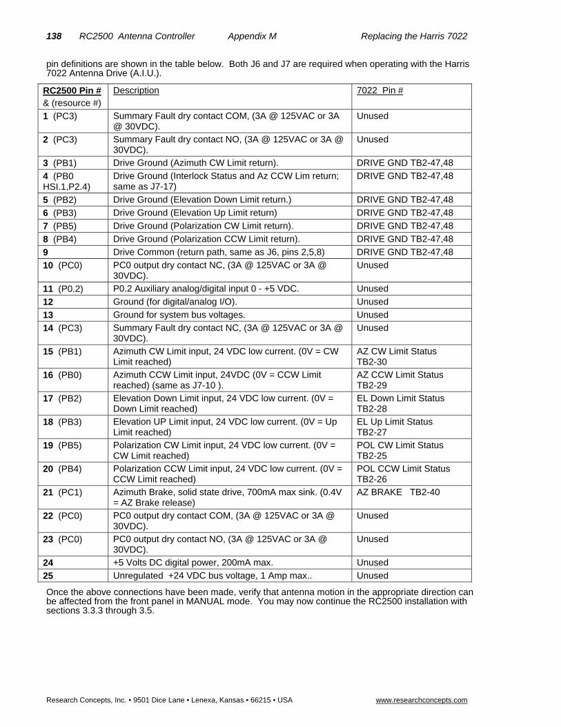
138 RC2500 Antenna Controller Appendix M Replacing the Harris 7022
Research Concepts, Inc. • 9501 Dice Lane • Lenexa, Kansas • 66215 • USA www.researchconcepts.com
pin definitions are shown in the table below. Both J6 and J7 are required when operating with the Harris 7022 Antenna Drive (A.I.U.).
RC2500 Pin # & (resource #)
Description 7022 Pin #
1 (PC3) Summary Fault dry contact COM, (3A @ 125VAC or 3A @ 30VDC).
Unused
2 (PC3) Summary Fault dry contact NO, (3A @ 125VAC or 3A @ 30VDC).
Unused
3 (PB1) Drive Ground (Azimuth CW Limit return). DRIVE GND TB2-47,48
4 (PB0 HSI.1,P2.4)
Drive Ground (Interlock Status and Az CCW Lim return; same as J7-17)
DRIVE GND TB2-47,48
5 (PB2) Drive Ground (Elevation Down Limit return.) DRIVE GND TB2-47,48
6 (PB3) Drive Ground (Elevation Up Limit return) DRIVE GND TB2-47,48
7 (PB5) Drive Ground (Polarization CW Limit return). DRIVE GND TB2-47,48
8 (PB4) Drive Ground (Polarization CCW Limit return). DRIVE GND TB2-47,48
9 Drive Common (return path, same as J6, pins 2,5,8) DRIVE GND TB2-47,48
10 (PC0) PC0 output dry contact NC, (3A @ 125VAC or 3A @ 30VDC).
Unused
11 (P0.2) P0.2 Auxiliary analog/digital input 0 - +5 VDC. Unused
12 Ground (for digital/analog I/O). Unused
13 Ground for system bus voltages. Unused
14 (PC3) Summary Fault dry contact NC, (3A @ 125VAC or 3A @ 30VDC).
Unused
15 (PB1) Azimuth CW Limit input, 24 VDC low current. (0V = CW Limit reached)
AZ CW Limit Status TB2-30
16 (PB0) Azimuth CCW Limit input, 24VDC (0V = CCW Limit reached) (same as J7-10 ).
AZ CCW Limit Status TB2-29
17 (PB2) Elevation Down Limit input, 24 VDC low current. (0V = Down Limit reached)
EL Down Limit Status TB2-28
18 (PB3) Elevation UP Limit input, 24 VDC low current. (0V = Up Limit reached)
EL Up Limit Status TB2-27
19 (PB5) Polarization CW Limit input, 24 VDC low current. (0V = CW Limit reached)
POL CW Limit Status TB2-25
20 (PB4) Polarization CCW Limit input, 24 VDC low current. (0V = CCW Limit reached)
POL CCW Limit Status TB2-26
21 (PC1) Azimuth Brake, solid state drive, 700mA max sink. (0.4V = AZ Brake release)
AZ BRAKE TB2-40
22 (PC0) PC0 output dry contact COM, (3A @ 125VAC or 3A @ 30VDC).
Unused
23 (PC0) PC0 output dry contact NO, (3A @ 125VAC or 3A @ 30VDC).
Unused
24 +5 Volts DC digital power, 200mA max. Unused
25 Unregulated +24 VDC bus voltage, 1 Amp max.. Unused
Once the above connections have been made, verify that antenna motion in the appropriate direction can be affected from the front panel in MANUAL mode. You may now continue the RC2500 installation with sections 3.3.3 through 3.5.

RC2500 Antenna Controller Appendix N Replacing the NPL 9000 139
Research Concepts, Inc. • 9501 Dice Lane • Lenexa, Kansas 66215 • USA www.researchconcepts.com
Appendix N – Replacing the NPL 9000 It is possible to use the RC2500 Antenna Control Unit (ACU) to replace the Northern Precision Labs, NPL 9000 series Antenna Controller and enjoy the industry-standard RCI operator interface and added capabilities of inclined-orbit tracking, multiple stored locations, and PC remote control. In order to be compatible with the Antenna and the Antenna Drive Unit (ADU), resolvers are placed on the azimuth, elevation and polarization pivot points. Information on the connection and use of resolvers is found in section 3.3.1. The firmware version for this unit is: version 1.14wna--, the date: 4.3.00, and the checksum: 'XX'. The RC2500 uses a modified 2_5KI_O1 as the interface PCB.
ADU Status Input
The NPL 9000 ADU has a single, 12VDC non-isolated output that is directly compatible with the limit inputs of the RC2500. This “Local Jog Control Active” signals to the ACU with 12VDC when the ADU is being driven from the Antenna-Pad-mounted jog controls. In response to this stimulous, the RC2500 will remove its Drive Supply from the “+” drives lines of the ADU and flash “ALARM – MAINTENANCE” on the LCD. In this state the RC2500 may not move the antenna. When the 12V signal is removed, the flashing alarm message disappears, the 12V supply is restored and control is resumed from the RC2500.
The “Local Jog Control Active” terminals of the ADU are connected to a limit input and limit return terminals of the RC2500. The former ESTOP input (PB7) is used for this input.
The antenna has limit switches to guard against over-travel on all three axes. These limit switches interface with the ADU. The RC2500 ACU operates with “soft” limits. That is, a given resolver position entered from the front panel, serves as a limit. The soft limits of course should be “inside” the antenna limit switches.
The Output of the RC2500 with its 10, 24V x 700mA open-collector drivers is directly compatible with the drive inputs to the NPL 9000 ADU. There are 6 drive inputs for the ADU. These are: AZ WEST, AZ EAST, EL UP, EL DOWN, POL CW, and POL CCW. When the NPL 9000 ADU is NOT in “Local Jog Mode” the entire interface is powered from the RC2500. ADU relays provide isolation between the grounding system of the RC2500 and the grounding system of the ADU. When “Local Jog Mode” is asserted at the ADU, the interface is powered by the ADU 12V source.
The standard I/O drive board of the RC2500 is modified to adapt to the NPL 9000 interface. A secondary regulator, reverse- and over-current protection stage is added to supply the required 12VDC when the RC2500 is powering the interface. The PC0 relay is used to apply this voltage to the drive interface and remove it in the case of errors or when the Local jog Mode is active. The six “+” lines of the drive interface running from the LMKDS are terminated at 3 previously unused pins of J7 supplying the +12V . The drive side of the RC2500 is also powered
The hardware interface between the RC2500 ACU and NPL 9000 ADU is summarized in the following tables showing all connections at J6 and J7. Following the interconnection tables, a description of the unique operating firmware for this version is given.
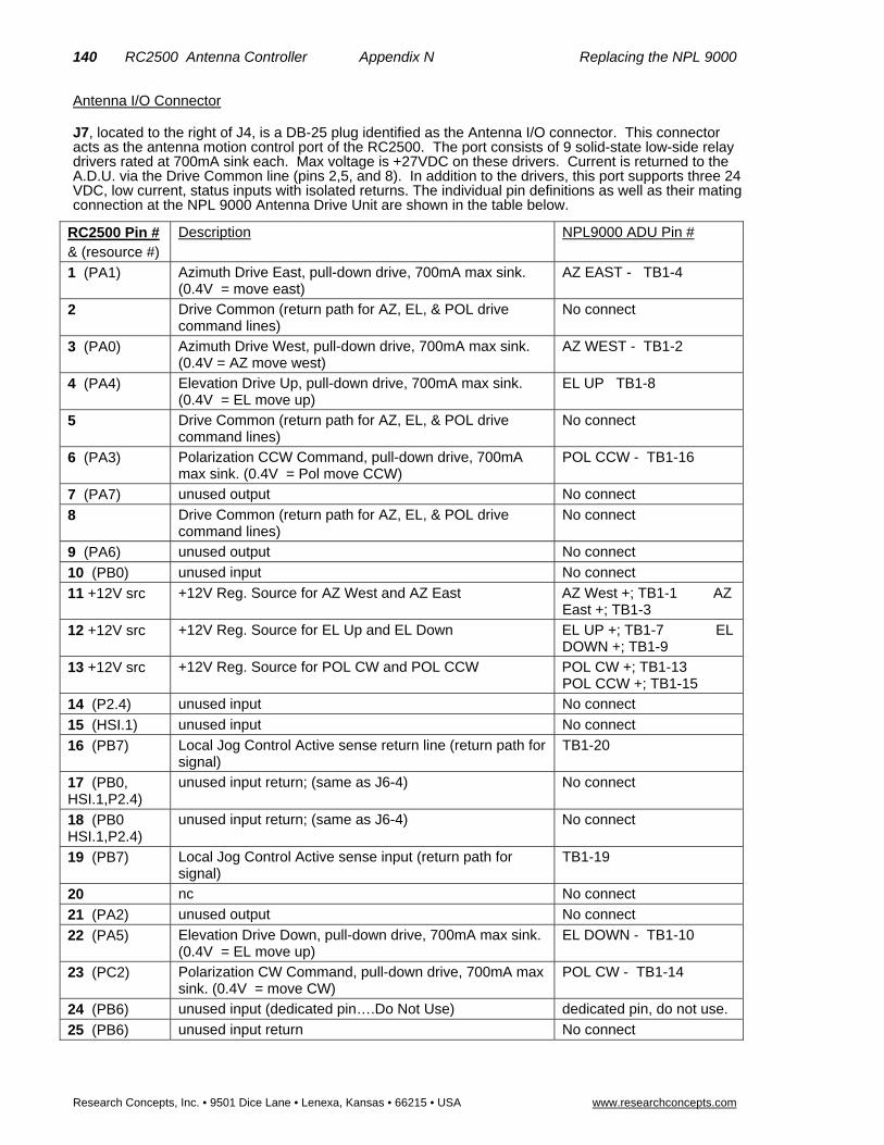
140 RC2500 Antenna Controller Appendix N Replacing the NPL 9000
Research Concepts, Inc. • 9501 Dice Lane • Lenexa, Kansas • 66215 • USA www.researchconcepts.com
Antenna I/O Connector
J7, located to the right of J4, is a DB-25 plug identified as the Antenna I/O connector. This connector acts as the antenna motion control port of the RC2500. The port consists of 9 solid-state low-side relay drivers rated at 700mA sink each. Max voltage is +27VDC on these drivers. Current is returned to the A.D.U. via the Drive Common line (pins 2,5, and 8). In addition to the drivers, this port supports three 24 VDC, low current, status inputs with isolated returns. The individual pin definitions as well as their mating connection at the NPL 9000 Antenna Drive Unit are shown in the table below.
RC2500 Pin # & (resource #)
Description NPL9000 ADU Pin #
1 (PA1) Azimuth Drive East, pull-down drive, 700mA max sink. (0.4V = move east)
AZ EAST - TB1-4
2 Drive Common (return path for AZ, EL, & POL drive command lines)
No connect
3 (PA0) Azimuth Drive West, pull-down drive, 700mA max sink. (0.4V = AZ move west)
AZ WEST - TB1-2
4 (PA4) Elevation Drive Up, pull-down drive, 700mA max sink. (0.4V = EL move up)
EL UP TB1-8
5 Drive Common (return path for AZ, EL, & POL drive command lines)
No connect
6 (PA3) Polarization CCW Command, pull-down drive, 700mA max sink. (0.4V = Pol move CCW)
POL CCW - TB1-16
7 (PA7) unused output No connect
8 Drive Common (return path for AZ, EL, & POL drive command lines)
No connect
9 (PA6) unused output No connect
10 (PB0) unused input No connect
11 +12V src +12V Reg. Source for AZ West and AZ East AZ West +; TB1-1 AZ East +; TB1-3
12 +12V src +12V Reg. Source for EL Up and EL Down EL UP +; TB1-7 EL DOWN +; TB1-9
13 +12V src +12V Reg. Source for POL CW and POL CCW POL CW +; TB1-13 POL CCW +; TB1-15
14 (P2.4) unused input No connect
15 (HSI.1) unused input No connect
16 (PB7) Local Jog Control Active sense return line (return path for signal)
TB1-20
17 (PB0, HSI.1,P2.4)
unused input return; (same as J6-4) No connect
18 (PB0 HSI.1,P2.4)
unused input return; (same as J6-4) No connect
19 (PB7) Local Jog Control Active sense input (return path for signal)
TB1-19
20 nc No connect
21 (PA2) unused output No connect
22 (PA5) Elevation Drive Down, pull-down drive, 700mA max sink. (0.4V = EL move up)
EL DOWN - TB1-10
23 (PC2) Polarization CW Command, pull-down drive, 700mA max sink. (0.4V = move CW)
POL CW - TB1-14
24 (PB6) unused input (dedicated pin….Do Not Use) dedicated pin, do not use.
25 (PB6) unused input return No connect

RC2500 Antenna Controller Appendix N Replacing the NPL 9000 141
Research Concepts, Inc. • 9501 Dice Lane • Lenexa, Kansas 66215 • USA www.researchconcepts.com
Auxiliary I/O Connection
J6, located directly above J7, is the Auxiliary I/O connector. This port, based on a DB-25 receptacle, supports isolated, axis-specific limit inputs (unused) as well as contact closures for summary faults and peripheral equipment control. A +5 VDC regulated output (200mA max), a +24 VDC unregulated output (1 Amp max), and an analog voltage input, all referenced to the RC2500 ground, are also available The individual pin definitions are shown in the table below. Both J6 and J7 are required when operating with the NPL 9000 Antenna Drive Unit (ADU).
RC2500 Pin #
& (resource #)
Description NPL9000 ADU Pin #
1 (PC3) Summary Fault dry contact COM, (3A @ 125VAC or 3A @ 30VDC).
Unused
2 (PC3) Summary Fault dry contact NO, (3A @ 125VAC or 3A @ 30VDC).
Unused
3 (PB1) unused input return No connect
4 (PB0 HSI.1,P2.4)
unused input return No connect
5 (PB2) unused input return No connect
6 (PB3) unused input return No connect
7 (PB5) unused input return No connect
8 (PB4) unused input return No connect
9 Drive Common (return path for AZ, EL, & POL drive command lines)
No connect
10 (PC0) PC0 output dry contact NC, (3A @ 125VAC or 3A @ 30VDC). (dedicated pin….Do Not Use)
dedicated pin, do not use.
11 (P0.2) P0.2 Auxiliary analog/digital input 0 - +5 VDC. Unused
12 Ground (for digital/analog I/O). Unused
13 Ground for system bus voltages. Unused
14 (PC3) Summary Fault dry contact NC, (3A @ 125VAC or 3A @ 30VDC).
Unused
15 (PB1) unused input No connect
16 (PB0) unused input (same as J7-10) No connect
17 (PB2) unused input No connect
18 (PB3) unused input No connect
19 (PB5) unused input No connect
20 (PB4) unused input No connect
21 (PC1) unused output No connect
22 (PC0) PC0 output dry contact COM, (3A @ 125VAC or 3A @ 30VDC). (dedicated pin….Do Not Use)
dedicated pin, do not use.
23 (PC0) PC0 output dry contact NO, (3A @ 125VAC or 3A @ 30VDC). (dedicated pin….Do Not Use)
dedicated pin, do not use.
24 +5 Volts DC digital power, 200mA max. Unused
25 Unregulated +24 VDC bus voltage, 0.3 Amp max.. Unused
Once the above connections have been made, verify that antenna motion in the appropriate direction can be affected from the front panel in MANUAL mode. You may now continue the RC2500 installation with sections 3.3.3 through 3.5.

142 RC2500 Antenna Controller Appendix N Replacing the NPL 9000
Research Concepts, Inc. • 9501 Dice Lane • Lenexa, Kansas • 66215 • USA www.researchconcepts.com
Setting Soft Limits for RC2500 Controllers which Replace the NPL 9000
Introduction
RC2500 software version 1.14 added support for user specified azimuth, elevation, and polarization limits. The Andrew LMKDS and NPL 9000 antenna interface units (AIU’s) do not provide limit status information to the RC2500. These AIU’s do process limit information to keep the antenna from moving past a physical limit but do not provide limit information to the RC2500. The software modification described here allows a user to input limit information to the RC2500. If the limit information is valid the RC2500 will not allow movements of the antenna outside of the region defined by the user-specified limits. When the antenna reaches a limit a limit indication will be displayed in the appropriate position display field when the controller is operating in a mode where antenna position information is displayed.
Setting the Soft Limits
The user specifies the position of the soft limits via the RC2500’s CONFIG mode. Six additional CONFIG mode items have been added. These are Azim CCW Limit, Azim CW Limit, Elev Down Limit, Elev Up Limit, Pol CCW Limit, and Pol CW Limit.
Here is the procedure for setting the soft limits (this assumes that the antenna’s mechanical limit switches are installed and properly adjusted)…
1. Verify that the Reverse Az Sensor Direction, Reverse El Sensor Direction, and Reverse Pol Sensor Direction CONFIG mode items have been properly initialized as described in section 3.xx.
2. Verify that the Azim Display Offset, Elev Display Offset, and Pol Display Offset CONFIG mode items have been initialized as described in section 3.xx.
3. To determine the location of the antenna’s azimuth CCW limit, from the RC2500’s MANUAL mode jog the antenna in the azimuth CCW direction until the antenna quits moving due to activation of the azimuth CCW limit switch. Jog the antenna in the azimuth CW direction approximately 3 degrees. Record the displayed azimuth position. The range of displayed azimuth position values is 0.0 to 359.99 degrees.
4. To determine the location of the antenna’s azimuth CW limit, from the RC2500’s MANUAL mode jog the antenna in the azimuth CW direction until the antenna quits moving due to activation of the azimuth CW limit switch. Jog the antenna in the azimuth CCW direction approximately 3 degrees. Record the displayed azimuth position.
5. From CONFIG mode, initialize the Azim CCW Limit and Azim CW Limit items to the azimuth positions recorded in steps 3 and 4 above. Be sure to terminate each entry by hitting the ENTER key.
6. The elevation down/up and polarization ccw/cw limits are determined in a similar manner. Note that the range of displayed elevation positions is –99.99 to 260.00 degrees and the range of displayed polarization positions is –99.9 to 260.0 degrees.
Corrupted Limits Alarm Messages
The soft limit data is stored in the controller’s non-volatile memory. The controller constantly checks the validity of non-volatile memory. If the controller detects that any of the limits are corrupt the ‘LIMITS ALARM’ error message will flash on the bottom row of the display.
Soft Limits Theory of Operation
The RC2500 is designed to interface with antenna’s that employ resolver type position sensors. The controller employs a resolver to digital converter (RDC) to convert the electrical outputs of the resolver to a 16 bit digital word. (0 to 65535 – referred to as the resolver position count) This digital word represents the angular deflection of the resolver input shaft relative to a reference position, 0.00 to 359.99 degrees. When the resolver output reaches 359.99 (65535) it rolls over to 0.00 (0), this is termed the resolver rollover point.
The controller displays azimuth positions as an angular value between 0.00 and 359.99 degrees. For the elevation axis the range of displayed values is –99.99 to 260.00. For the polarization axis, the range of

RC2500 Antenna Controller Appendix N Replacing the NPL 9000 143
Research Concepts, Inc. • 9501 Dice Lane • Lenexa, Kansas 66215 • USA www.researchconcepts.com
displayed values is –99.9 to 260.0. The key to understanding the mapping of resolver position to display angle is to recognize that an indicated position of –99.99 degrees is equivalent to 260.01 degrees.
The resolver input shaft is attached to the antenna pivot points. The controller expects the sensed position to increase as the antenna moves azimuth CW, elevation UP, or polarization CW. The Reverse Az/El/Pol Sensor Direction CONFIG mode items can be set to 1 to reverse the sense of the resolvers indicated direction of rotation. When the Reverse Sensor Direction flag is set to 1 for a given axis, the 16 bit output of the RDC is subtracted from 65535 and the result becomes the resolver position count.
It is advantageous for operators if the antenna controller displays the antenna’s actual azimuth, elevation, and polarization pointing angles. If the couplers that connect the shafts of the resolvers to the antenna pivot points are carefully adjusted the resolvers can directly indicate the antenna pointing angles about each axis. This can cause problems, however, because the RC2500’s auto move routines cannot operate properly if the resolver rollover points occur in the antenna’s active range.
The Azim/Elev/Pol Display Offset CONFIG mode items specify an angle that is added to each resolver’s sensed position (adjusted for the Reverse Sensor Direction CONFIG mode items). The Display Offset values can be any value between –179.99 and 180.00 degrees. The addition of the Offsets is performed in a modulo 360 manner. The offset is added to the adjusted resolver reading and the result is adjusted by adding or subtracting 360 degrees so that the display angle lies in the range of values appropriate for that axis: 0.00 to 359.99 for the azimuth axis and –99.99 to 260.00 for the elevation and polarization axis.
The user specifies a soft limit by entering an angle at the soft limit CONFIG mode prompt. That angle corresponds to a display angle for the axis whose limit is being entered. The controller will accept any valid display angle for the axis whose limit is being set for either limit associated with that axis if the offset associated with that axis is valid (a valid offset means that the checksum – described later in this paragraph - agrees with the offset value and the offset is greater than –180.00 and less than or equal to +180.00). If the angle entered is not a valid display angle for the axis associated with the limit or the offset associated with that axis is not valid the controller will display ‘INVALID DATA’ when the user hits the ENTER key to terminate the data entry. The offset for that axis is subtracted from the value entered. The resulting angle is converted into a resolver position count and that value is stored in the controller’s non-volatile memory. Also stored in memory is a checksum. The checksum is mathematically related to the resolver position count that corresponds to the limit that is being set. The purpose of the checksum is to allow the controller to periodically test the limit value to see if the controller’s non-volatile memory has been corrupted.
When the user is prompted to set a soft limit the data entry field for the soft limit will contain the current value of the soft limit for that axis if the following are true…
a) The checksum for both limits associated with that axis are valid.
b) The offset for the axis being set is valid (the offset value agrees with its checksum and the value of the offset is greater than –180.00 and less than or equal to +180.00).
c) The value of the upper limit associated with that axis (azimuth CW, elevation up, or polarization CW) is greater than or equal to the lower limit associated with that axis (azimuth CCW, elevation down, or polarization CW).
If these conditions are not met the data field will contain ‘*’ characters. The last condition implies that a soft limit value that is accepted by the controller will not be displayed at the data prompt if its magnitude relative to the other limit associated with that axis does not meet the criteria outlined in item c above.
For a given axis, limit indications will be displayed and antenna motion disabled when operating outside the region defined by the limits if the conditions outlined in items a, b, and c above are met and RDC alarm is not active. If an RDC alarm is active the position display field for that axis will contain ‘*’ characters. The alarm display system will display the ‘LIMITS ALARM’ message if items a and c given above are not met for each of the limits associated with the azimuth, elevation, and polarization axis.
Resetting the Limits
When the Reset System Data CONFIG mode item is employed to reset system data the lower limits for each axis (azimuth CCW, elevation down, and polarization CCW) are set to 0 and the upper limit for each axis (azimuth CW, elevation up, and polarization CW) are set to 65535. The checksums for all limits are also validated. This will disable the display of the ‘LIMITS ALARM’ message.
In certain cases it may be advantageous to reset the limits without resetting all system data. The following procedure can be employed to reset the limits associated with a given axis.

144 RC2500 Antenna Controller Appendix N Replacing the NPL 9000
Research Concepts, Inc. • 9501 Dice Lane • Lenexa, Kansas • 66215 • USA www.researchconcepts.com
a) Record the value of the display offset associated with the axis.
b) Reset the display offset associated with the axis by entering 0.0 at the appropriate CONFIG mode prompt.
c) Reset the lower limit associated with the axis (azimuth CCW, elevation down, or polarization CCW) by entering 0.0 at the appropriate CONFIG mode prompt.
d) If resetting the azimuth limits set the Azimuth CW Limit to 359.99. If resetting the elevation or polarization limits, set the Elevation Up Limit or Polarization CW Limit to –0.01.
e) Reinitialize the offset associated with the axis whose limits are being reset to the value recorded in step a above.
Rc25_lmkds_add.doc completed 4.2.00 by SMM

RC2500 Antenna Controller Appendix O Replacing the Andrew APC100/ APC 300 145
Research Concepts, Inc. • 9501 Dice Lane • Lenexa, Kansas 66215 • USA www.researchconcepts.com
Appendix O – Replacing the Andrew APC 100/ APC 300 It is possible to use the RC2500 Antenna Control Unit (ACU) to replace the Andrew APC 100 / APC 300 Antenna Controller and enjoy the industry-standard RCI operator interface. In order to be compatible with the Antenna and the Andrew Local Motor Controller (LMKDS), resolvers are placed on the azimuth, elevation and polarization pivot points. Information on the connection and use of resolvers is found in section 3.3.1. For retrofit installations, the existing resolvers may work if they operate with a 4.4Vrms, 2KHz reference and have a transformation ration of 2:1. The firmware version for this unit is: version 1.14 waa--, the date: 4.3.00, and the checksum: '34'. The RC2500 uses a modified 2_5KI_O1 as the interface PCB.
LMKDS Input The Output of the RC2500 with its 10, 24V x 700mA open-collector drivers is directly compatible with the drive inputs to the LMKDS Local Motor Controller. There are 10 drive inputs for the LMKDS. These are: AZ EAST, AZ WEST, AZ FAST, AZ SLOW, EL DOWN, EL UP, EL FAST, EL SLOW, POL CCW, and POL CW. The entire interface is powered from the RC2500. Optoisolators provide isolation between the grounding system of the RC2500 and the grounding system of the LMKDS.
The antenna has limit switches to guard against over-travel on all three axes. These limit switches interface with the LMKDS. In the APC100/300 system, this limit information is not transmitted to the ACU. The RC2500 ACU operates with “soft” limits. That is, a given resolver position entered from the front panel, serves as a limit. The soft limits of course should be “inside” the antenna limit switches.
The standard I/O drive board of the RC2500 is modified to adapt to the LMKDS interface. A secondary regulator and over-current protection stage is added to supply the required 12VDC when the RC2500 is powering the interface. The PC0 relay is used to apply this voltage to the drive interface and remove it in the case of errors.
The hardware interface between the RC2500 ACU and LMKDS is summarized in the following tables showing all connections at J6 and J7. Following the interconnection tables, a description of the unique operating firmware for this version is given.

146 RC2500 Antenna Controller Appendix O Replacing the Andrew APC100/ APC 300
Research Concepts, Inc. • 9501 Dice Lane • Lenexa, Kansas • 66215 • USA www.researchconcepts.com
Antenna I/O Connector
J7, located to the right of J4, is a DB-25 plug identified as the Antenna I/O connector. This connector acts as the antenna motion control port of the RC2500. The port consists of 9 solid-state low-side relay drivers rated at 700mA sink each. Max voltage is +27VDC on these drivers. Current is returned to the A.I.U. via the Drive Common line (pins 2,5, and 8). In addition to the drivers, this port supports three 24 VDC, low current, status inputs with isolated returns. The individual pin definitions as well as their mating connection at the LMKDS are shown in the table below.
RC2500 Pin # & (resource #)
Description LMKDS Pin #
1 (PA1) Azimuth Drive East, pull-down drive, 700mA max sink. (0.4V = move east)
AZ EAST TB1-2
2 Drive Common (return path for AZ, EL, & POL drive command lines)
No connect
3 (PA0) Azimuth Drive West, pull-down drive, 700mA max sink. (0.4V = AZ move west)
AZ WEST TB1-4
4 (PA4) Elevation Drive Up, pull-down drive, 700mA max sink. (0.4V = EL move up)
EL UP TB1-12
5 Drive Common (return path for AZ, EL, & POL drive command lines)
No connect
6 (PA3) Polarization CCW Command, pull-down drive, 700mA max sink. (0.4V = Pol move CCW)
POL CCW TB1-18
7 (PA7) Elevation Slow, pull-down drive, 700mA max sink. (0.4V = EL move slow)
EL SLOW TB1-16
8 Drive Common (return path for AZ, EL, & POL drive command lines)
No connect
9 (PA6) Elevation Fast, pull-down drive, 700mA max sink. (0.4V = EL move fast)
EL FAST TB1-14
10 (PB0) unused input No connect
11 +12V src +12V Reg. Source for AZ West and AZ East AZ West +; TB1-1 AZ East +; TB1-3
12 +12V src +12V Reg. Source for EL Up and EL Down EL UP +; TB1-7 EL DOWN +; TB1-9
13 +12V src +12V Reg. Source for POL CW and POL CCW POL CW +; TB1-13 POL CCW +; TB1-15
14 (P2.4) unused input No connect
15 (HSI.1) unused input No connect
16 (PB7) unused input return No connect
17 (PB0, HSI.1,P2.4)
unused input return; (same as J6-4) No connect
18 (PB0 HSI.1,P2.4)
unused input return; (same as J6-4) No connect
19 (PB7) unused input No connect
20 nc No connect
21 (PA2) Azimuth Fast, pull-down drive, 700mA max sink. (0.4V = AZ move fast)
AZ FAST TB1-6
22 (PA5) Elevation Drive Down, pull-down drive, 700mA max sink. (0.4V = EL move down)
EL DOWN TB1-10
23 (PC2) Polarization CW Command, pull-down drive, 700mA max sink. (0.4V = Pol move CW)
POL CW TB1-20
24 (PB6) unused input dedicated pin, do not use
25 (PB6) unused input return No connect

RC2500 Antenna Controller Appendix O Replacing the Andrew APC100/ APC 300 147
Research Concepts, Inc. • 9501 Dice Lane • Lenexa, Kansas 66215 • USA www.researchconcepts.com
Auxiliary I/O Connection
J6, located directly above J7, is the Auxiliary I/O connector. This port, based on a DB-25 receptacle, supports isolated, axis-specific limit inputs (unused) as well as contact closures for summary faults and peripheral equipment control. A +5 VDC regulated output (200mA max), a +24 VDC unregulated output (1 Amp max), and an analog voltage input, all referenced to the RC2500 ground, are also available The individual pin definitions are shown in the table below. Both J6 and J7 are required when operating with the LMKDS.
RC2500 Pin # & (resource #)
Description LMKDS Pin #
1 (PC3) Summary Fault dry contact COM, (3A @ 125VAC or 3A @ 30VDC).
Unused
2 (PC3) Summary Fault dry contact NO, (3A @ 125VAC or 3A @ 30VDC).
Unused
3 (PB1) unused input return No connect
4 (PB0 HSI.1,P2.4)
unused input return No connect
5 (PB2) unused input return No connect
6 (PB3) unused input return No connect
7 (PB5) unused input return No connect
8 (PB4) unused input return No connect
9 Drive Common (return path for AZ, EL, & POL drive command lines)
No connect
10 (PC0) PC0 output dry contact NC, (3A @ 125VAC or 3A @ 30VDC).
dedicated pin, do not use.
11 (P0.2) P0.2 Auxiliary analog/digital input 0 - +5 VDC. Unused
12 Ground (for digital/analog I/O). Unused
13 Ground for system bus voltages. Unused
14 (PC3) Summary Fault dry contact NC, (3A @ 125VAC or 3A @ 30VDC).
Unused
15 (PB1) unused input No connect
16 (PB0) unused input (same as J7-10) No connect
17 (PB2) unused input No connect
18 (PB3) unused input No connect
19 (PB5) unused input No connect
20 (PB4) unused input No connect
21 (PC1) Azimuth Slow, pull-down drive, 700mA max sink. (0.4V = AZ move Slow)
AZ SLOW TB1-8
22 (PC0) PC0 output dry contact COM, (3A @ 125VAC or 3A @ 30VDC).
dedicated pin, do not use.
23 (PC0) PC0 output dry contact NO, (3A @ 125VAC or 3A @ 30VDC).
dedicated pin, do not use.
24 +5 Volts DC digital power, 200mA max. Unused
25 Unregulated +24 VDC bus voltage, 1 Amp max.. Unused
Once the above connections have been made, verify that antenna motion in the appropriate direction can be affected from the front panel in MANUAL mode. You may now continue the RC2500 installation with sections 3.3.3 through 3.5.

148 RC2500 Antenna Controller Appendix O Replacing the Andrew APC100/ APC 300
Research Concepts, Inc. • 9501 Dice Lane • Lenexa, Kansas • 66215 • USA www.researchconcepts.com
Setting Soft Limits for RC2500 Controllers which Replace Andrew Products
Introduction
RC2500 software version 1.14 added support for user specified azimuth, elevation, and polarization limits. The Andrew LMKDS and NPL 9000 antenna interface units (AIU’s) do not provide limit status information to the RC2500. These AIU’s do process limit information to keep the antenna from moving past a physical limit but do not provide limit information to the RC2500. The software modification described here allows a user to input limit information to the RC2500. If the limit information is valid the RC2500 will not allow movements of the antenna outside of the region defined by the user-specified limits. When the antenna reaches a limit a limit indication will be displayed in the appropriate position display field when the controller is operating in a mode where antenna position information is displayed.
Setting the Soft Limits
The user specifies the position of the soft limits via the RC2500’s CONFIG mode. Six additional CONFIG mode items have been added. These are Azim CCW Limit, Azim CW Limit, Elev Down Limit, Elev Up Limit, Pol CCW Limit, and Pol CW Limit.
Here is the procedure for setting the soft limits (this assumes that the antenna’s mechanical limit switches are installed and properly adjusted)…
1. Verify that the Reverse Az Sensor Direction, Reverse El Sensor Direction, and Reverse Pol Sensor Direction CONFIG mode items have been properly initialized as described in section 3.xx.
2. Verify that the Azim Display Offset, Elev Display Offset, and Pol Display Offset CONFIG mode items have been initialized as described in section 3.xx.
3. To determine the location of the antenna’s azimuth CCW limit, from the RC2500’s MANUAL mode jog the antenna in the azimuth CCW direction until the antenna quits moving due to activation of the azimuth CCW limit switch. Jog the antenna in the azimuth CW direction approximately 3 degrees. Record the displayed azimuth position. The range of displayed azimuth position values is 0.0 to 359.99 degrees.
4. To determine the location of the antenna’s azimuth CW limit, from the RC2500’s MANUAL mode jog the antenna in the azimuth CW direction until the antenna quits moving due to activation of the azimuth CW limit switch. Jog the antenna in the azimuth CCW direction approximately 3 degrees. Record the displayed azimuth position.
5. From CONFIG mode, initialize the Azim CCW Limit and Azim CW Limit items to the azimuth positions recorded in steps 3 and 4 above. Be sure to terminate each entry by hitting the ENTER key.
6. The elevation down/up and polarization ccw/cw limits are determined in a similar manner. Note that the range of displayed elevation positions is –99.99 to 260.00 degrees and the range of displayed polarization positions is –99.9 to 260.0 degrees.
Corrupted Limits Alarm Messages
The soft limit data is stored in the controller’s non-volatile memory. The controller constantly checks the validity of non-volatile memory. If the controller detects that any of the limits are corrupt the ‘LIMITS ALARM’ error message will flash on the bottom row of the display.
Soft Limits Theory of Operation
The RC2500 is designed to interface with antenna’s that employ resolver type position sensors. The controller employs a resolver to digital converter (RDC) to convert the electrical outputs of the resolver to a 16 bit digital word. (0 to 65535 – referred to as the resolver position count) This digital word represents the angular deflection of the resolver input shaft relative to a reference position, 0.00 to 359.99 degrees. When the resolver output reaches 359.99 (65535) it rolls over to 0.00 (0), this is termed the resolver rollover point.
The controller displays azimuth positions as an angular value between 0.00 and 359.99 degrees. For the elevation axis the range of displayed values is –99.99 to 260.00. For the polarization axis, the range of

RC2500 Antenna Controller Appendix O Replacing the Andrew APC100/ APC 300 149
Research Concepts, Inc. • 9501 Dice Lane • Lenexa, Kansas 66215 • USA www.researchconcepts.com
displayed values is –99.9 to 260.0. The key to understanding the mapping of resolver position to display angle is to recognize that an indicated position of –99.99 degrees is equivalent to 260.01 degrees.
The resolver input shaft is attached to the antenna pivot points. The controller expects the sensed position to increase as the antenna moves azimuth CW, elevation UP, or polarization CW. The Reverse Az/El/Pol Sensor Direction CONFIG mode items can be set to 1 to reverse the sense of the resolvers indicated direction of rotation. When the Reverse Sensor Direction flag is set to 1 for a given axis, the 16 bit output of the RDC is subtracted from 65535 and the result becomes the resolver position count.
It is advantageous for operators if the antenna controller displays the antenna’s actual azimuth, elevation, and polarization pointing angles. If the couplers that connect the shafts of the resolvers to the antenna pivot points are carefully adjusted the resolvers can directly indicate the antenna pointing angles about each axis. This can cause problems, however, because the RC2500’s auto move routines cannot operate properly if the resolver rollover points occur in the antenna’s active range.
The Azim/Elev/Pol Display Offset CONFIG mode items specify an angle that is added to each resolver’s sensed position (adjusted for the Reverse Sensor Direction CONFIG mode items). The Display Offset values can be any value between –179.99 and 180.00 degrees. The addition of the Offsets is performed in a modulo 360 manner. The offset is added to the adjusted resolver reading and the result is adjusted by adding or subtracting 360 degrees so that the display angle lies in the range of values appropriate for that axis: 0.00 to 359.99 for the azimuth axis and –99.99 to 260.00 for the elevation and polarization axis.
The user specifies a soft limit by entering an angle at the soft limit CONFIG mode prompt. That angle corresponds to a display angle for the axis whose limit is being entered. The controller will accept any valid display angle for the axis whose limit is being set for either limit associated with that axis if the offset associated with that axis is valid (a valid offset means that the checksum – described later in this paragraph - agrees with the offset value and the offset is greater than –180.00 and less than or equal to +180.00). If the angle entered is not a valid display angle for the axis associated with the limit or the offset associated with that axis is not valid the controller will display ‘INVALID DATA’ when the user hits the ENTER key to terminate the data entry. The offset for that axis is subtracted from the value entered. The resulting angle is converted into a resolver position count and that value is stored in the controller’s non-volatile memory. Also stored in memory is a checksum. The checksum is mathematically related to the resolver position count that corresponds to the limit that is being set. The purpose of the checksum is to allow the controller to periodically test the limit value to see if the controller’s non-volatile memory has been corrupted.
When the user is prompted to set a soft limit the data entry field for the soft limit will contain the current value of the soft limit for that axis if the following are true…
a) The checksum for both limits associated with that axis are valid.
b) The offset for the axis being set is valid (the offset value agrees with its checksum and the value of the offset is greater than –180.00 and less than or equal to +180.00).
c) The value of the upper limit associated with that axis (azimuth CW, elevation up, or polarization CW) is greater than or equal to the lower limit associated with that axis (azimuth CCW, elevation down, or polarization CW).
If these conditions are not met the data field will contain ‘*’ characters. The last condition implies that a soft limit value that is accepted by the controller will not be displayed at the data prompt if its magnitude relative to the other limit associated with that axis does not meet the criteria outlined in item c above.
For a given axis, limit indications will be displayed and antenna motion disabled when operating outside the region defined by the limits if the conditions outlined in items a, b, and c above are met and RDC alarm is not active. If an RDC alarm is active the position display field for that axis will contain ‘*’ characters. The alarm display system will display the ‘LIMITS ALARM’ message if items a and c given above are not met for each of the limits associated with the azimuth, elevation, and polarization axis.
Resetting the Limits
When the Reset System Data CONFIG mode item is employed to reset system data the lower limits for each axis (azimuth CCW, elevation down, and polarization CCW) are set to 0 and the upper limit for each axis (azimuth CW, elevation up, and polarization CW) are set to 65535. The checksums for all limits are also validated. This will disable the display of the ‘LIMITS ALARM’ message.
In certain cases it may be advantageous to reset the limits without resetting all system data. The following procedure can be employed to reset the limits associated with a given axis.

150 RC2500 Antenna Controller Appendix O Replacing the Andrew APC100/ APC 300
Research Concepts, Inc. • 9501 Dice Lane • Lenexa, Kansas • 66215 • USA www.researchconcepts.com
a) Record the value of the display offset associated with the axis.
b) Reset the display offset associated with the axis by entering 0.0 at the appropriate CONFIG mode prompt.
c) Reset the lower limit associated with the axis (azimuth CCW, elevation down, or polarization CCW) by entering 0.0 at the appropriate CONFIG mode prompt.
d) If resetting the azimuth limits set the Azimuth CW Limit to 359.99. If resetting the elevation or polarization limits, set the Elevation Up Limit or Polarization CW Limit to –0.01.
e) Reinitialize the offset associated with the axis whose limits are being reset to the value recorded in step a above.
Rc25_lmkds_add.doc completed 4.2.00 by SMM

RC2500 Antenna Controller Using the RC2500 with AZ over EL Mounts 151
Research Concepts, Inc. • 9501 Dice Lane • Lenexa, Kansas 66215 • USA www.researchconcepts.com
Appendix P – Using the RC2500 with Azimuth Over Elevation Antenna Mounts
A version of the RC2500 software is available that can perform inclined orbit satellite tracking with azimuth over elevation type antenna mounts. Software versions that support azimuth over elevation mounts have an ‘e’ in the third digit of the suffix appended to the software version number that is displayed as the controller powers up. For example, ‘v1.13w_e__’ indicates support for azimuth over elevation type mounts.
Antenna Setup
For azimuth over elevation type mounts, the controller assumes that the mount has been aligned such that when the antenna is pointing south (true, not magnetic), changing the elevation angle by 1 degree changes the antenna pointing angle by 1 degree. When the mount is adjusted in this manner and the antenna is pointing either due east or due west, movement of the antenna in elevation just causes the antenna polarization to change - there is no change in the antenna's pointing angle.
Another way to state this is that the mount must be configured in a manner similar to a polar mount which has been adjusted to properly track the satellites in geostationary orbit. An azimuth over elevation mount is basically a polar mount with a variable latitude angle and a declination value of zero.
Sometimes azimuth over elevation antenna mounts are configured such that when the mount is aligned with the satellite of interest one degree of elevation movement results in one degree of antenna pointing angle change. If this is the case specify the antenna longitude (via the Antenna Longitude CONFIG mode item) to be the same as that of the satellite.
SMM, 2.14.00

152 RC2500 Antenna Controller Appendix Q Working with the SA 8151
Research Concepts, Inc. • 9501 Dice Lane • Lenexa, Kansas • 66215 • USA www.researchconcepts.com
Appendix Q – Working with the SA 8151 It is possible to use the RC2500 Antenna Control Unit (ACU) to replace the Scientific Atlanta SA 8040 Antenna Controller when operated with the SA 8151 Local Control Unit (LCU) and enjoy the industry-standard RCI operator interface and added capabilities of inclined-orbit tracking, multiple stored locations, and PC remote control. In order to be compatible with the Antenna and the LCU, resolvers are placed on the azimuth, elevation and polarization (if required) pivot points. Information on the connection and use of resolvers is found in section 3.3.1. The firmware version for this unit is: version 1.07wra-p, the date: 3.17.98, and the checksum: '34'. The RC2500 uses a modified 2_5KI_O1 as the interface PCB.
LCU Limit Status Outputs
The SA8151 LCU has four non-isolated outputs that are directly compatible with the limit inputs of the RC2500. These outputs connect to the limit return lines of J6. A 5V source located in the LCU is connected to all high-side limit input lines. The limits are directly connected to a normally open set of contacts in the antenna-mounted limit switch. When the limit is reached, the contacts close, allowing current to flow through the RC2500 optoisolator. The normally-closed side of the limit switch is used to interrupt drive power to the motors. The “safe” operating region is defined as the non- conducting state of the drivers. That is a pull-down occurring on the limit return line (5VDC is always on the limit input) of the RC2500 input terminal indicates a limit has been reached. A high voltage (+5VDC) on the limit return line indicates that a limit has not been reached. Note that this is different from other control schemes where the conducting state indicates the safe operating region.
This “Local / Remote” switch located on the control panel of the LCU signals to the ACU with 5VDC when the LCU is to be driven from the ACU. This 5VDC supply also powers the drive side interface. The LCU is switched to “Local” the 5VDC goes to zero and, the RC2500 will flash “ALARM – MAINTENANCE” on the LCD. In this state the RC2500 may not move the antenna. When the 5V signal is returned, the flashing alarm message disappears, and control is resumed from the RC2500.
The limit inputs formerly used for AZ fault, EL fault, and EStop are wired out of the circuit.
ACU Drive Outputs
The Output circuitry of the RC2500 is modified to be compatible with the drive inputs to the SA 8151 LCU. There are 4 drive inputs for the LCU. These are: AZ CW, AZ CCW, EL UP, and EL DOWN. Optionally, POL CW, and POL CCW may also be controlled. They are active high, that is they move the antenna when 5V is applied to the line. The RC2500 drives these lines with opto-isolated darlington drives in a pull-up configuration.
The standard I/O drive board of the RC2500 is modified to adapt to the SA 8151 interface. VR1 and VR2 are removed from the circuit. A MPTE5 transient protection diode is installed between pins 1 and 2 and a jumper is installed between pins 1 and 3 of VR1. A 0.2A-trip, resettable fuse is installed between pins 1 and 2 of VR2. IC’s U2, U4, and U6 are removed and replaced with DIP headers supporting connections between pin 9 and pin 8, and between pin 10 and pin 6. The limit inputs formerly used for AZ fault, EL fault, and EStop are wired out of the circuit by connecting U8 pin 12 to U8 pin 11, U8 pin 13 to U8 pin 14, and .U9 pin 10 to U9.
The hardware interface between the RC2500 ACU and SA 8151 LCU is summarized in the following tables showing all connections at J6 and J7 of the ACU.

RC2500 Antenna Controller Appendix Q Working with the SA 8151 153
Research Concepts, Inc. • 9501 Dice Lane • Lenexa, Kansas 66215 • USA www.researchconcepts.com
Antenna I/O Connector
J7, located to the right of J4, is a DB-25 plug identified as the Antenna I/O connector. This connector acts as the antenna motion control port of the RC2500. The port consists of 6 solid-state high-side Darlington drivers rated at 20mA source each. 5V supply current is sourced from the LCU Local/Remote switch via the Maintenance status input. ACU limit inputs are sourced with 5V from a non-switched LCU 5V supply. In addition to the drivers, this port supports three 24 VDC, low current, status inputs with isolated returns. The individual pin definitions as well as their mating connection at the NPL 9000 Antenna Drive Unit are shown in the table below. All voltages are referenced to LCU return TB1-8.
RC2500 Pin # & (resource #)
Description SA 8151 LCU Pin #
1 (PA1) Azimuth Drive CW, pull-up drive, 20mA max source. (5 V = move CW)
AZ CW - TB2-2
2 Drive Common (return path for AZ, EL, & POL drive command lines)
LCU return TB1-8
3 (PA0) Azimuth Drive CCW, pull-up drive, 20mA max source. (5 V = move CCW)
AZ CCW - TB2-1
4 (PA4) Elevation Drive Up, pull-up drive, 20mA max source. (5 V = move Up)
EL UP TB1-2
5 Drive Common (return path for AZ, EL, & POL drive command lines)
No connect
6 (PA3) Elevation Drive Down, pull-up drive, 20mA max source. (5 V = move Down)
EL Down TB1-1
7 (PA7) Polarization Drive CW, pull-up drive, 20mA max source. (5 V = move CW)
No connect T.B.D.
8 Drive Common (return path for AZ, EL, & POL drive command lines)
No connect
9 (PA6) Polarization Drive CCW, pull-up drive, 20mA max source. (5 V = move CW)
No connect T.B.D.
10 (PB0) reserved input (same as J6 pin16) No connect 11 nc unused pin No connect 12 nc unused pin No connect 13 nc unused pin No connect 14 (P2.4) unused input No connect 15 (HSI.1) unused input No connect 16 (PB7) unused input No connect 17 (PB0, HSI.1,P2.4)
unused input return; (same as J6-4) No connect
18 (PB0 HSI.1,P2.4)
unused input return; (same as J6-4) No connect
19 (PB7) unused input No connect 20 unused pin No connect 21 (PA2) unused output No connect 22 (PA5) unused output No connect 23 (PC2) unused output No connect 24 (PB6) Local/Remote Status input, 5 VDC low current, (5V
= LCU in remote mode…RC2500 active) Local / Remote TB1-6
25 (PB6) Local/Remote Status input return LCU return TB1-8
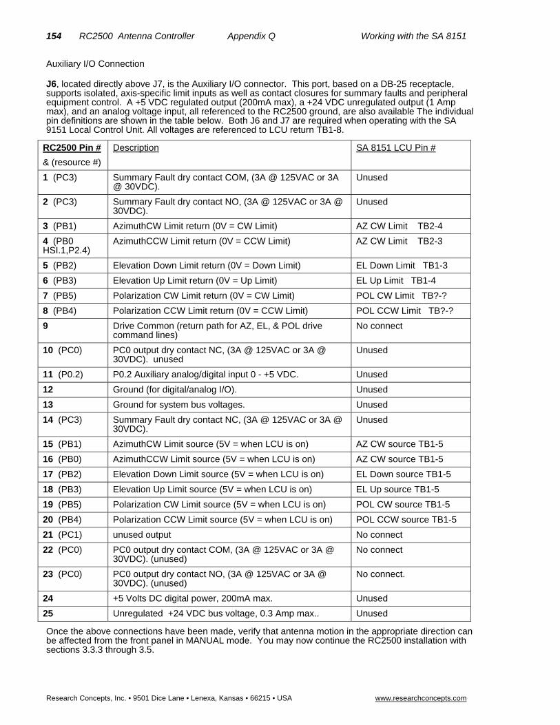
154 RC2500 Antenna Controller Appendix Q Working with the SA 8151
Research Concepts, Inc. • 9501 Dice Lane • Lenexa, Kansas • 66215 • USA www.researchconcepts.com
Auxiliary I/O Connection
J6, located directly above J7, is the Auxiliary I/O connector. This port, based on a DB-25 receptacle, supports isolated, axis-specific limit inputs as well as contact closures for summary faults and peripheral equipment control. A +5 VDC regulated output (200mA max), a +24 VDC unregulated output (1 Amp max), and an analog voltage input, all referenced to the RC2500 ground, are also available The individual pin definitions are shown in the table below. Both J6 and J7 are required when operating with the SA 9151 Local Control Unit. All voltages are referenced to LCU return TB1-8.
RC2500 Pin #
& (resource #)
Description SA 8151 LCU Pin #
1 (PC3) Summary Fault dry contact COM, (3A @ 125VAC or 3A @ 30VDC).
Unused
2 (PC3) Summary Fault dry contact NO, (3A @ 125VAC or 3A @ 30VDC).
Unused
3 (PB1) AzimuthCW Limit return (0V = CW Limit) AZ CW Limit TB2-4
4 (PB0 HSI.1,P2.4)
AzimuthCCW Limit return (0V = CCW Limit) AZ CW Limit TB2-3
5 (PB2) Elevation Down Limit return (0V = Down Limit) EL Down Limit TB1-3
6 (PB3) Elevation Up Limit return (0V = Up Limit) EL Up Limit TB1-4
7 (PB5) Polarization CW Limit return (0V = CW Limit) POL CW Limit TB?-?
8 (PB4) Polarization CCW Limit return (0V = CCW Limit) POL CCW Limit TB?-?
9 Drive Common (return path for AZ, EL, & POL drive command lines)
No connect
10 (PC0) PC0 output dry contact NC, (3A @ 125VAC or 3A @ 30VDC). unused
Unused
11 (P0.2) P0.2 Auxiliary analog/digital input 0 - +5 VDC. Unused
12 Ground (for digital/analog I/O). Unused
13 Ground for system bus voltages. Unused
14 (PC3) Summary Fault dry contact NC, (3A @ 125VAC or 3A @ 30VDC).
Unused
15 (PB1) AzimuthCW Limit source (5V = when LCU is on) AZ CW source TB1-5
16 (PB0) AzimuthCCW Limit source (5V = when LCU is on) AZ CW source TB1-5
17 (PB2) Elevation Down Limit source (5V = when LCU is on) EL Down source TB1-5
18 (PB3) Elevation Up Limit source (5V = when LCU is on) EL Up source TB1-5
19 (PB5) Polarization CW Limit source (5V = when LCU is on) POL CW source TB1-5
20 (PB4) Polarization CCW Limit source (5V = when LCU is on) POL CCW source TB1-5
21 (PC1) unused output No connect
22 (PC0) PC0 output dry contact COM, (3A @ 125VAC or 3A @ 30VDC). (unused)
No connect
23 (PC0) PC0 output dry contact NO, (3A @ 125VAC or 3A @ 30VDC). (unused)
No connect.
24 +5 Volts DC digital power, 200mA max. Unused
25 Unregulated +24 VDC bus voltage, 0.3 Amp max.. Unused
Once the above connections have been made, verify that antenna motion in the appropriate direction can be affected from the front panel in MANUAL mode. You may now continue the RC2500 installation with sections 3.3.3 through 3.5.

RC2500 Antenna Controller Appendix R Working with the SSE AIU 155
Research Concepts, Inc. • 9501 Dice Lane • Lenexa, Kansas 66215 • USA www.researchconcepts.com
Appendix R – Working with the SSE Antenna Interface Unit It is possible to use the RC2500 Antenna Control Unit (ACU) to replace the Superior Satellite Engineers (SSE) PC-based ACU and enjoy the industry-standard RCI operator interface and added capabilities of inclined-orbit tracking, multiple stored locations, and PC remote control. The SSE ACU-AIU-Antenna system was manufactured between 1988 and 1991. The SSE Antenna Interface Unit (AIU) mounted at the antenna pad has a single speed AZ/EL drive which uses 115VAC single-phase reversing motors. The Polarization angle was set by either a Polarotor interface, a Ferrorotator, or a standard Seavey-type motorized feedhorn with pot feedback. The RC2500 does not support the polarotor or ferrorotator interface. With additional circuitry, the RC2500 can operate with a Seavey-type feedhorn See Appendix H.
The Wiring between the Outside Controller Box and the Indoor unit is an 11-wire interface. 5 wires carry the AZ and EL potentiometer voltages, + 5 V and –5V sources and a signal ground. A single wire carries the drive signal for the Polarotor interface. These 6 wires will be unused in the RC2500 retrofit. The remaining 5 wires carry the drive interface for AZ and EL motion. They are: AZ Right, AZ Left, EL Up, EL Down and Relay Return. A +12VDC supply must be used from the AIU to power the high side of the drive relays in the ACU. The Low-side of the relays are presented to the ACU to be connected to the Relay Return line, energizing the circuit and moving the antenna.
In order to be compatible with the Antenna and the AIU, resolvers are placed on the azimuth, elevation and polarization (if required) pivot points. Cabling will be added to support these resolvers. Information on the connection and use of resolvers is found in section 3.3.1. The RC2500 uses a standard 2_5KI_O1 as the interface PCB.
(unused) RC2500 Limit Switch Inputs
We will use the summary limit version of the software. The summary limit input shall be permanently disabled internally at the ACU. No limit indications will be available at the ACU. When encountering a limit for greater than 3 seconds, the ACU will indicate a jammed condition. This error must be cleared (from the front panel) and the antenna may be moved away from the limit position. The AZ fault, EL fault, and ESTOP input will be permanently disabled at the ACU.
Drive Connections:
J7 on the RC2500 has six solid-state pull-down relay drivers that will directly connect to the four normally-open drive lines coming from the AIU and optionally to 2 Polarization drive lines. The current is returned through 3 “Drive Common” lines connected to the AIU “Relay Return” lines. The +12V supply and a return line of the AIU must be brought in to the ACU. The (now) unused wires that formerly carried the AZ pot wiper and EL pot wiper may be used for this purpose. This is required to power the drive circuitry on the AIU side of the opto-isolation barrier. The AZ Fast, EL Fast, and Drive Enable lines shall not be used. All drive connections will be made at the male DB-25 connector J7.
The hardware interface between the RC2500 ACU and SSE AIU is summarized in the following table showing all connections at J7 of the ACU.

156 RC2500 Antenna Controller Appendix R Working with the SSE AIU
Research Concepts, Inc. • 9501 Dice Lane • Lenexa, Kansas • 66215 • USA www.researchconcepts.com
Antenna I/O Connector
J7, located to the right of J4, is a DB-25 plug identified as the Antenna I/O connector. This connector acts as the antenna motion control port of the RC2500. The port consists of 6 solid-state high-side Darlington drivers rated at 20mA source each.
RC2500 Pin # & (resource #)
Description SSE Signal Name
1 (PA1) Azimuth Drive CW, pull-up drive, 20mA max source. (5 V = move CW).
AZ Right
2 Drive Common (return path for AZ, EL, & POL drive command lines) )
Relay Return
3 (PA0) Azimuth Drive CCW, pull-up drive, 20mA max source. (5 V = move CCW)
AZ Left
4 (PA4) Elevation Drive Up, pull-up drive, 20mA max source. (5 V = move Up
EL Up
5 Drive Common (return path for AZ, EL, & POL drive command lines) )
Relay Return
6 (PA3) Elevation Drive Down, pull-up drive, 20mA max source. (5 V = move Down
EL Down
7 (PA7) Polarization Drive CW, pull-up drive, 20mA max source. (5 V = move CW)
No connect T.B.D.
8 Drive Common (return path for AZ, EL, & POL drive command lines) )
Relay Return
9 (PA6) Polarization Drive CCW, pull-up drive, 20mA max source. (5 V = move CW)
No connect T.B.D.
10 (PB0) reserved input (same as J6 pin16) No connect
11 nc unused pin No connect
12 nc unused pin No connect
13 nc unused pin No connect
14 (P2.4) unused input No connect
15 (HSI.1) unused input No connect
16 (PB7) unused input No connect
17 (PB0, HSI.1,P2.4)
unused input return; (same as J6-4) No connect
18 (PB0 HSI.1,P2.4)
unused input return; (same as J6-4) No connect
19 (PB7) unused input No connect
20 unused pin No connect
21 (PA2) unused output No connect
22 (PA5) unused output No connect
23 (PC2) unused output No connect
24 (PB6) Local/Remote Status input, 12 VDC low current, (12V = AIU in remote mode…RC2500 active)
+12V supply from AIU
25 (PB6) Local/Remote Status input return Relay Return

RC2500 Antenna Controller Appendix S Andrew Plug Compatible Controller 157
Research Concepts, Inc. • 9501 Dice Lane • Lenexa, Kansas 66215 • USA www.researchconcepts.com
Appendix S – Andrew Plug Compatible Controller A new version of the RC2500 Antenna Controller has been produced. It is plug compatible with Andrew APC100 and APC300 Controllers. This allows the user to enjoy the industry-standard qualities of the RC2500 on their existing Andrew antennas. The RC2500-ANDREW uses the same DB-50 Receptacle (DB-50R) control connector and DB50 Plug (DB-50P) resolver connector as the Andrew Controllers. This allows the direct field replacement without cable changes.
This appendix consists of two major parts, the first, a description of hardware and interconnects and the second, a description of the new “Soft Limits” portion of the configuration menu. This appendix is meant as a supplement to the main RC2500 manual. Please refer to the main manual text for installation guidance unless this appendix calls out a change.
Note that there are no Hard Limit inputs used in this version of the RC2500. Limit switches on the antenna interact only with the Antenna Interface Unit (AIU) halting motion at that level. The RC2500-ANDREW controller uses “soft” limits. Soft limits are stored positions, set during installation, that halt the antenna motion before the “hard” limits are reached.
After the Hardware and Software sections of this appendix, 5 sections of the I/O PCB schematic are reproduced along with two diagrams showing the component layout of the I/O PCB. Finally, a diagram showing the interconnects between the original RC2500 resolver connectors and the DB-50P is shown.
Hardware Description and Interconnects
The RC2500 Andrew controller uses a larger housing. While still 2 rack-units tall, the RC2500-ANDREW version is 12 inches deep versus the 9-inch deep standard RC2500. This version of the RC2500 uses the same front panel, display, and processor board as the standard RC2500. A new I/O PCB is used which accommodates the Andrew APC100/300 features.
The RC2500 back panel differs from the standard RC2500. A back Panel drawing showing the new connectors is in Figure S-1. Connector J1 is now a DB-25P. Like the DB-15R of the standard RC2500, it is used to support AGC input, contact closure, and digital i/o capability. J2 is now a DB-50R used to take as input all three of the resolvers. J2 is described below. J3 is now the PC remote control connector (RS-422) this has the same characteristics as the J5 referred to in section 3.3 and 3.3.4. J4 is an auxiliary input connector and is described below. Finally, J5 is the motor control connector. In a normal, non-tracking installation, only J2 and J5 are used.
The following four tables describe the new connectors J1, J2, J4, and J5 found on the RC2500-ANDREW Antenna Controller.

158 RC2500 Antenna Controller Appendix S Andrew Plug Compatible Controller
Research Concepts, Inc. • 9501 Dice Lane • Lenexa, Kansas • 66215 • USA www.researchconcepts.com
AGC Input Connector, J1 This section replaces Section 3.3.3 of the RC2500 Manual.
AGC Interface Connection J1, located on the left side of the back panel is a DB-25P (plug). It supports the basic pin set for an Andrew AGC Connector and has several additional features. J1 is used primarily for AGC signal input while the RC2500B is tracking inclined orbit satellites. The RC2500A model does not support inclined orbit tracking modes. In addition to the AGC input function, J1 supports 4 bits of digital I/O and various bus voltages that allow for future expansion. In the APC100/300 AGC interface, there are two form C relay contacts. The RC2500 interface supports just one of these, PC3-relay which acts as a Summary Alarm.
The AGC voltage or received signal strength voltage from the system receiver must be between –15VDC and +15VDC. The signal may be either positive-going or negative-going for an increasing signal strength (selectable in the configuration menu). When the magnitude of the difference between the “on satellite” voltage and “off satellite” voltage is less than 1.3 volts AGC channel 1 should be used. For voltage differences greater than 1.3 volts use AGC channel 2. Four potentiometer adjustments at the back panel set the gain and offset for the two channels.
A shielded pair such as Alpha 1292C should be used to minimize external noise pickup on the AGC line. The shield should be connected at the RC2500 system ground and open circuited at the receiver or modem. For further discussion of the AGC inputs, AGC input tuning, and inclined-orbit tracking see Chapter 4.
The individual pin definitions of J1 ( for the APC100/300 interface and the RC2500 interface) are shown in the table below.
J1 Pin # RC2500ANDREW Signal Description APC300 Pin # & Description DB25P
1 HI CH1 INPUT AGC 1 Signal Input 1 Primary Beacon +
2 LO AGC Signal Return 2 Primary Return
3 HI CH2 INPUT AGC 2 Signal Input 3 Secondary Beacon +
4 LO AGC Signal Return 4 Secondary Return
5 not used not used
6 CH1 Select Output PC3-RY-NC 6 Selected Beacon
7 COM PC3-RY-COM 7 Tally Relay
8 CH2 Select Output PC3-RY-NO 8 Internal Connection
9 not used not used
10 not supported 10 FAULT/POWER OFF
11 not supported 11 COM SUMMARY ALARM
12 not supported 12 TALLY RELAY
13 not used not used
14 PC4 Digital I/O not used
15 PC5 Digital I/O not used
16 PC6 Digital I/O not used
17 PC7 Digital I/O not used
18 Digital Ground not used
19 +5 VOLT DC DIG POWER 500mA max. not used
20 Unreg. +24 VDC 500mA max. not used
21 Power Ground not used
22 -12 VOLTS DC 50mA max. not used
23 +12 VOLTS DC 50mA max not used
24 AGC 2 OFFSET TEST POINT not used
25 AGC 1 OFFSET TEST POINT not used
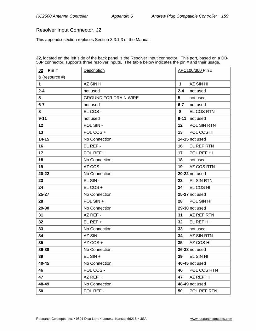
RC2500 Antenna Controller Appendix S Andrew Plug Compatible Controller 159
Research Concepts, Inc. • 9501 Dice Lane • Lenexa, Kansas 66215 • USA www.researchconcepts.com
Resolver Input Connector, J2
This appendix section replaces Section 3.3.1.3 of the Manual.
J2, located on the left side of the back panel is the Resolver Input connector. This port, based on a DB-50P connector, supports three resolver inputs. The table below indicates the pin # and their usage.
J2 Pin #
& (resource #)
Description APC100/300 Pin #
1 AZ SIN HI 1 AZ SIN HI
2-4 not used 2-4 not used
5 GROUND FOR DRAIN WIRE 5 not used
6-7 not used 6-7 not used
8 EL COS - 8 EL COS RTN
9-11 not used 9-11 not used
12 POL SIN - 12 POL SIN RTN
13 POL COS + 13 POL COS HI
14-15 No Connection 14-15 not used
16 EL REF - 16 EL REF RTN
17 POL REF + 17 POL REF HI
18 No Connection 18 not used
19 AZ COS - 19 AZ COS RTN
20-22 No Connection 20-22 not used
23 EL SIN - 23 EL SIN RTN
24 EL COS + 24 EL COS HI
25-27 No Connection 25-27 not used
28 POL SIN + 28 POL SIN HI
29-30 No Connection 29-30 not used
31 AZ REF - 31 AZ REF RTN
32 EL REF + 32 EL REF HI
33 No Connection 33 not used
34 AZ SIN - 34 AZ SIN RTN
35 AZ COS + 35 AZ COS HI
36-38 No Connection 36-38 not used
39 EL SIN + 39 EL SIN HI
40-45 No Connection 40-45 not used
46 POL COS - 46 POL COS RTN
47 AZ REF + 47 AZ REF HI
48-49 No Connection 48-49 not used
50 POL REF - 50 POL REF RTN
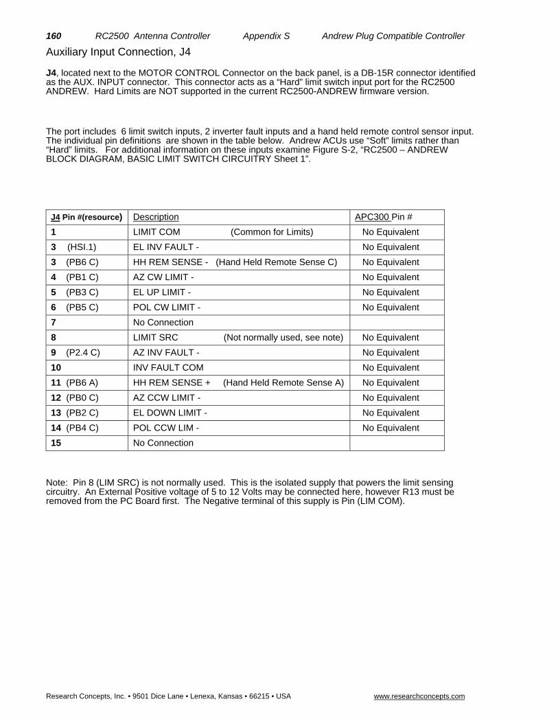
160 RC2500 Antenna Controller Appendix S Andrew Plug Compatible Controller
Research Concepts, Inc. • 9501 Dice Lane • Lenexa, Kansas • 66215 • USA www.researchconcepts.com
Auxiliary Input Connection, J4
J4, located next to the MOTOR CONTROL Connector on the back panel, is a DB-15R connector identified as the AUX. INPUT connector. This connector acts as a “Hard” limit switch input port for the RC2500 ANDREW. Hard Limits are NOT supported in the current RC2500-ANDREW firmware version.
The port includes 6 limit switch inputs, 2 inverter fault inputs and a hand held remote control sensor input. The individual pin definitions are shown in the table below. Andrew ACUs use “Soft” limits rather than “Hard” limits. For additional information on these inputs examine Figure S-2, “RC2500 – ANDREW BLOCK DIAGRAM, BASIC LIMIT SWITCH CIRCUITRY Sheet 1”.
J4 Pin #(resource) Description APC300 Pin #
1 LIMIT COM (Common for Limits) No Equivalent
3 (HSI.1) EL INV FAULT - No Equivalent
3 (PB6 C) HH REM SENSE - (Hand Held Remote Sense C) No Equivalent
4 (PB1 C) AZ CW LIMIT - No Equivalent
5 (PB3 C) EL UP LIMIT - No Equivalent
6 (PB5 C) POL CW LIMIT - No Equivalent
7 No Connection
8 LIMIT SRC (Not normally used, see note) No Equivalent
9 (P2.4 C) AZ INV FAULT - No Equivalent
10 INV FAULT COM No Equivalent
11 (PB6 A) HH REM SENSE + (Hand Held Remote Sense A) No Equivalent
12 (PB0 C) AZ CCW LIMIT - No Equivalent
13 (PB2 C) EL DOWN LIMIT - No Equivalent
14 (PB4 C) POL CCW LIM - No Equivalent
15 No Connection
Note: Pin 8 (LIM SRC) is not normally used. This is the isolated supply that powers the limit sensing circuitry. An External Positive voltage of 5 to 12 Volts may be connected here, however R13 must be removed from the PC Board first. The Negative terminal of this supply is Pin (LIM COM).

RC2500 Antenna Controller Appendix S Andrew Plug Compatible Controller 161
Research Concepts, Inc. • 9501 Dice Lane • Lenexa, Kansas 66215 • USA www.researchconcepts.com
Motor Control Connector, J5
J5, located on the right side of the back panel, is a DB-50R connector identified as the MOTOR CONTROL connector. This connector acts as the antenna motion control port of the RC2500-ANDREW ACU .
The port consists of 10 solid-state sinking drivers and a +12 Volt source for driving the optical isolator inputs of the Andrew outdoor unit. The individual pin definitions as well as their mating connection at the APC300 are shown in the table below. For additional information on this port examine Figure S-3, RC2500 – ANDREW BLOCK DIAGRAM, OUTPUT CIRCUITRY Sheet 2.
This information is meant to replace that contained in section 3.3.2 of the RC2500 Manual.
J5 Pin#(resource) Description APC300 Pin #
1 (PA1) Azimuth Drive East *, (0.4V = AZ move East) 1 AZ EAST -
2 (PA0) Azimuth Drive West *, (0.4V = AZ move West) 2 AZ WEST -
3 (PA2) Azimuth Drive Fast, (0.4V = AZ move Fast) 3 AZ FAST -
4 (PC1) Azimuth Drive Slow, (0.4V = AZ move Slow) 4 AZ SLOW -
5 (PA5) Elevation Drive Down, (0.4V = EL move Down) 5 EL DOWN -
6 (PA4) Elevation Drive Up, (0.4V = EL move Up) 6 EL UP -
7 (PA6) Elevation Drive Fast, (0.4V = EL move Fast) 7 EL FAST -
8 (PA7) Elevation Drive Slow, (0.4V = EL move Slow) 8 EL SLOW -
9 (PA3) Polarization Drive CCW, (0.4V = Pol move CCW) 9 POL CCW -
10 (PC2) Polarization Drive CW, (0.4V = Pol move CW) 10 POL CW -
11 – 17 No Connection No Connection
18 Drive +12 V 18 AZ EAST +
19 Drive +12 V 19 AZ WEST +
20 Drive +12 V 20 AZ FAST +
21 Drive +12 V 21 AZ SLOW +
22 Drive +12 V 22 EL DOWN +
23 Drive +12 V 23 EL UP +
24 Drive +12 V 24 EL FAST +
25 Drive +12 V 25 EL SLOW +
26 Drive +12 V 26 POL CCW +
27 Drive +12 V 27 POL CW +
28 Drive +12 V No connection
29 Drive +12 V No connection
30-50 No Connection No Connection
*NOTE: Azimuth directions are given for the Northern Hemisphere, reverse these for use in the Southern Hemisphere.

162 RC2500 Antenna Controller Appendix S Andrew Plug Compatible Controller
Research Concepts, Inc. • 9501 Dice Lane • Lenexa, Kansas • 66215 • USA www.researchconcepts.com
Software Features
The software features of the RC2500A/B Andrew are identical to those described in the manual except for the addition of support for “Soft” Limits. The standard RC2500 supports “Hard” limits. Hard limits are limits that exist due to the operation of an electromechanical switch on the antenna. “Soft” limits are those that exist only in the memory of the ACU.
Setting Soft Limits for RC2500 Controllers which Replace Andrew Products
Introduction
RC2500 software version 1.14 added support for user specified azimuth, elevation, and polarization limits. The Andrew LMKDS and NPL 9000 antenna interface units (AIU’s) do not provide limit status information to the RC2500. These AIU’s do process limit information to keep the antenna from moving past a physical limit but do not provide limit information to the RC2500. The software modification described here allows a user to input limit information to the RC2500. If the limit information is valid the RC2500 will not allow movements of the antenna outside of the region defined by the user-specified limits. When the antenna reaches a limit a limit indication will be displayed in the appropriate position display field when the controller is operating in a mode where antenna position information is displayed.
Setting the Soft Limits
The user specifies the position of the soft limits via the RC2500’s CONFIG mode. Six additional CONFIG mode items have been added. These are Azim CCW Limit, Azim CW Limit, Elev Down Limit, Elev Up Limit, Pol CCW Limit, and Pol CW Limit.
Here is the procedure for setting the soft limits (this assumes that the antenna’s mechanical limit switches are installed and properly adjusted)…
7. Verify that the Reverse Az Sensor Direction, Reverse El Sensor Direction, and Reverse Pol Sensor Direction CONFIG mode items have been properly initialized as described in section 3.xx.
8. Verify that the Azim Display Offset, Elev Display Offset, and Pol Display Offset CONFIG mode items have been initialized as described in section 3.xx.
9. To determine the location of the antenna’s azimuth CCW limit, from the RC2500’s MANUAL mode jog the antenna in the azimuth CCW direction until the antenna quits moving due to activation of the azimuth CCW limit switch. Jog the antenna in the azimuth CW direction approximately 3 degrees. Record the displayed azimuth position. The range of displayed azimuth position values is 0.0 to 359.99 degrees.
10. To determine the location of the antenna’s azimuth CW limit, from the RC2500’s MANUAL mode jog the antenna in the azimuth CW direction until the antenna quits moving due to activation of the azimuth CW limit switch. Jog the antenna in the azimuth CCW direction approximately 3 degrees. Record the displayed azimuth position.
11. From CONFIG mode, initialize the Azim CCW Limit and Azim CW Limit items to the azimuth positions recorded in steps 3 and 4 above. Be sure to terminate each entry by hitting the ENTER key.
12. The elevation down/up and polarization ccw/cw limits are determined in a similar manner. Note that the range of displayed elevation positions is –99.99 to 260.00 degrees and the range of displayed polarization positions is –99.9 to 260.0 degrees.
Corrupted Limits Alarm Messages
The soft limit data is stored in the controller’s non-volatile memory. The controller constantly checks the validity of non-volatile memory. If the controller detects that any of the limits are corrupt the ‘LIMITS ALARM’ error message will flash on the bottom row of the display.
Soft Limits Theory of Operation
The RC2500 is designed to interface with antenna’s that employ resolver type position sensors. The controller employs a resolver to digital converter (RDC) to convert the electrical outputs of the resolver to a 16 bit digital word. (0 to 65535 – referred to as the resolver position count) This digital word represents the angular deflection of the resolver input shaft relative to a reference position, 0.00 to 359.99 degrees. When the resolver output reaches 359.99 (65535) it rolls over to 0.00 (0), this is termed the resolver rollover point.
The controller displays azimuth positions as an angular value between 0.00 and 359.99 degrees. For the elevation axis the range of displayed values is –99.99 to 260.00. For the polarization axis, the range of displayed values is –99.9 to 260.0. The key to understanding the mapping of resolver position to display angle is to recognize that an indicated position of –99.99 degrees is equivalent to 260.01 degrees.

RC2500 Antenna Controller Appendix S Andrew Plug Compatible Controller 163
Research Concepts, Inc. • 9501 Dice Lane • Lenexa, Kansas 66215 • USA www.researchconcepts.com
The resolver input shaft is attached to the antenna pivot points. The controller expects the sensed position to increase as the antenna moves azimuth CW, elevation UP, or polarization CW. The Reverse Az/El/Pol Sensor Direction CONFIG mode items can be set to 1 to reverse the sense of the resolvers indicated direction of rotation. When the Reverse Sensor Direction flag is set to 1 for a given axis, the 16 bit output of the RDC is subtracted from 65535 and the result becomes the resolver position count.
It is advantageous for operators if the antenna controller displays the antenna’s actual azimuth, elevation, and polarization pointing angles. If the couplers that connect the shafts of the resolvers to the antenna pivot points are carefully adjusted the resolvers can directly indicate the antenna pointing angles about each axis. This can cause problems, however, because the RC2500’s auto move routines cannot operate properly if the resolver rollover points occur in the antenna’s active range.
The Azim/Elev/Pol Display Offset CONFIG mode items specify an angle that is added to each resolver’s sensed position (adjusted for the Reverse Sensor Direction CONFIG mode items). The Display Offset values can be any value between –179.99 and 180.00 degrees. The addition of the Offsets is performed in a modulo 360 manner. The offset is added to the adjusted resolver reading and the result is adjusted by adding or subtracting 360 degrees so that the display angle lies in the range of values appropriate for that axis: 0.00 to 359.99 for the azimuth axis and –99.99 to 260.00 for the elevation and polarization axis.
The user specifies a soft limit by entering an angle at the soft limit CONFIG mode prompt. That angle corresponds to a display angle for the axis whose limit is being entered. The controller will accept any valid display angle for the axis whose limit is being set for either limit associated with that axis if the offset associated with that axis is valid (a valid offset means that the checksum – described later in this paragraph - agrees with the offset value and the offset is greater than –180.00 and less than or equal to +180.00). If the angle entered is not a valid display angle for the axis associated with the limit or the offset associated with that axis is not valid the controller will display ‘INVALID DATA’ when the user hits the ENTER key to terminate the data entry. The offset for that axis is subtracted from the value entered. The resulting angle is converted into a resolver position count and that value is stored in the controller’s non-volatile memory. Also stored in memory is a checksum. The checksum is mathematically related to the resolver position count that corresponds to the limit that is being set. The purpose of the checksum is to allow the controller to periodically test the limit value to see if the controller’s non-volatile memory has been corrupted.
When the user is prompted to set a soft limit the data entry field for the soft limit will contain the current value of the soft limit for that axis if the following are true…
d) The checksum for both limits associated with that axis are valid. e) The offset for the axis being set is valid (the offset value agrees with its checksum and the
value of the offset is greater than –180.00 and less than or equal to +180.00). f) The value of the upper limit associated with that axis (azimuth CW, elevation up, or polarization
CW) is greater than or equal to the lower limit associated with that axis (azimuth CCW, elevation down, or polarization CW).
If these conditions are not met the data field will contain ‘*’ characters. The last condition implies that a soft limit value that is accepted by the controller will not be displayed at the data prompt if its magnitude relative to the other limit associated with that axis does not meet the criteria outlined in item c above.
For a given axis, limit indications will be displayed and antenna motion disabled when operating outside the region defined by the limits if the conditions outlined in items a, b, and c above are met and RDC alarm is not active. If an RDC alarm is active the position display field for that axis will contain ‘*’ characters. The alarm display system will display the ‘LIMITS ALARM’ message if items a and c given above are not met for each of the limits associated with the azimuth, elevation, and polarization axis.
Resetting the Limits
When the Reset System Data CONFIG mode item is employed to reset system data the lower limits for each axis (azimuth CCW, elevation down, and polarization CCW) are set to 0 and the upper limit for each axis (azimuth CW, elevation up, and polarization CW) are set to 65535. The checksums for all limits are also validated. This will disable the display of the ‘LIMITS ALARM’ message.
In certain cases it may be advantageous to reset the limits without resetting all system data. The following procedure can be employed to reset the limits associated with a given axis.
f) Record the value of the display offset associated with the axis. g) Reset the display offset associated with the axis by entering 0.0 at the appropriate CONFIG
mode prompt. h) Reset the lower limit associated with the axis (azimuth CCW, elevation down, or polarization
CCW) by entering 0.0 at the appropriate CONFIG mode prompt.

164 RC2500 Antenna Controller Appendix S Andrew Plug Compatible Controller
Research Concepts, Inc. • 9501 Dice Lane • Lenexa, Kansas • 66215 • USA www.researchconcepts.com
i) If resetting the azimuth limits set the Azimuth CW Limit to 359.99. If resetting the elevation or polarization limits, set the Elevation Up Limit or Polarization CW Limit to –0.01.
j) Reinitialize the offset associated with the axis whose limits are being reset to the value recorded in step a above.
Rc25_lmkds_add.doc completed 4.2.00 by SMM
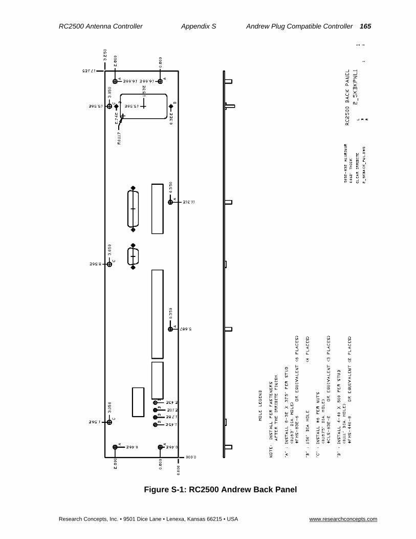
RC2500 Antenna Controller Appendix S Andrew Plug Compatible Controller 165
Research Concepts, Inc. • 9501 Dice Lane • Lenexa, Kansas 66215 • USA www.researchconcepts.com
Figure S-1: RC2500 Andrew Back Panel
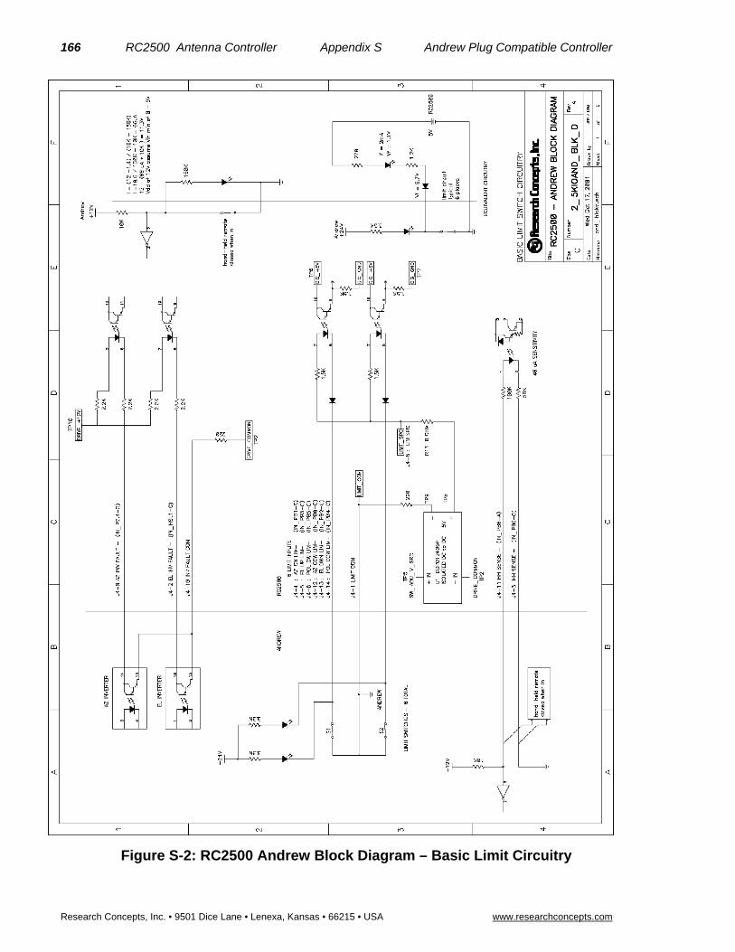
166 RC2500 Antenna Controller Appendix S Andrew Plug Compatible Controller
Research Concepts, Inc. • 9501 Dice Lane • Lenexa, Kansas • 66215 • USA www.researchconcepts.com
Figure S-2: RC2500 Andrew Block Diagram – Basic Limit Circuitry

RC2500 Antenna Controller Appendix S Andrew Plug Compatible Controller 167
Research Concepts, Inc. • 9501 Dice Lane • Lenexa, Kansas 66215 • USA www.researchconcepts.com
Figure S-3: RC2500 Andrew Block Diagram – Output Circuitry

168 RC2500 Antenna Controller Appendix S Andrew Plug Compatible Controller
Research Concepts, Inc. • 9501 Dice Lane • Lenexa, Kansas • 66215 • USA www.researchconcepts.com
Figure S-4: RC2500 I/O and Power Section – Line Power
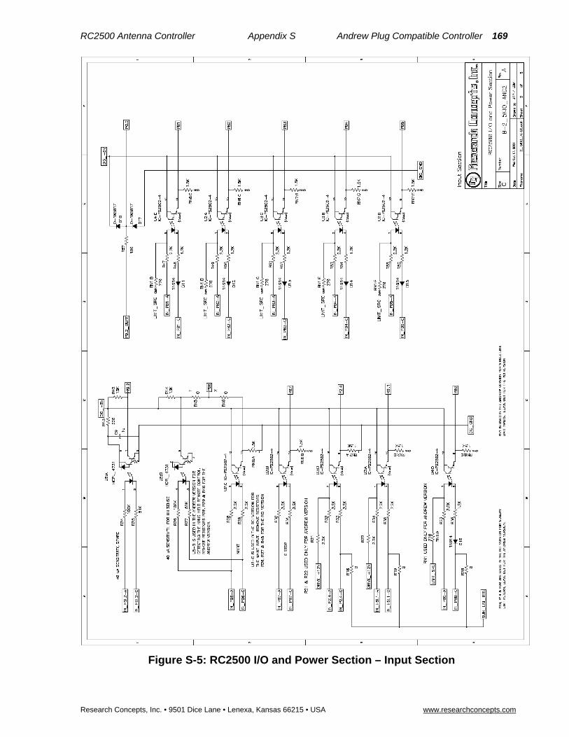
RC2500 Antenna Controller Appendix S Andrew Plug Compatible Controller 169
Research Concepts, Inc. • 9501 Dice Lane • Lenexa, Kansas 66215 • USA www.researchconcepts.com
Figure S-5: RC2500 I/O and Power Section – Input Section

170 RC2500 Antenna Controller Appendix S Andrew Plug Compatible Controller
Research Concepts, Inc. • 9501 Dice Lane • Lenexa, Kansas • 66215 • USA www.researchconcepts.com
Figure S-6: RC2500 I/O and Power Section – Output Section

RC2500 Antenna Controller Appendix S Andrew Plug Compatible Controller 171
Research Concepts, Inc. • 9501 Dice Lane • Lenexa, Kansas 66215 • USA www.researchconcepts.com
Figure S-7: RC2500 I/O and Power Section – I/O_Connect

172 RC2500 Antenna Controller Appendix S Andrew Plug Compatible Controller
Research Concepts, Inc. • 9501 Dice Lane • Lenexa, Kansas • 66215 • USA www.researchconcepts.com
Figure S-8: RC2500 I/O and Power Section – Configuration Details

RC2500 Antenna Controller Appendix S Andrew Plug Compatible Controller 173
Research Concepts, Inc. • 9501 Dice Lane • Lenexa, Kansas 66215 • USA www.researchconcepts.com
Figure S-9: RC2500 – Common Assembly Details

174 RC2500 Antenna Controller Appendix S Andrew Plug Compatible Controller
Research Concepts, Inc. • 9501 Dice Lane • Lenexa, Kansas • 66215 • USA www.researchconcepts.com
Figure S-10: RC2500 – Andrew Assembly Details
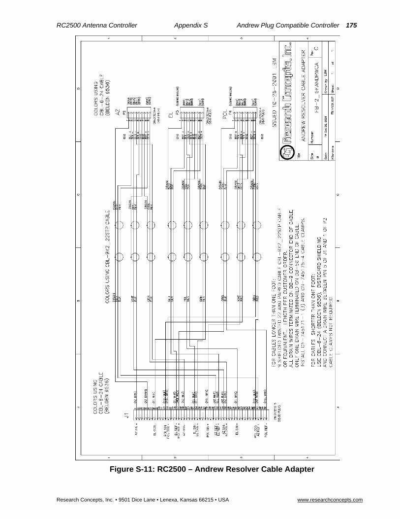
RC2500 Antenna Controller Appendix S Andrew Plug Compatible Controller 175
Research Concepts, Inc. • 9501 Dice Lane • Lenexa, Kansas 66215 • USA www.researchconcepts.com
Figure S-11: RC2500 – Andrew Resolver Cable Adapter

176 RC2500 Antenna Controller Appendix T Version 1.15 RC2500 Support on Special Features
Research Concepts, Inc. • 9501 Dice Lane • Lenexa, Kansas • 66215 • USA www.researchconcepts.com
Appendix T – Version 1.15 Addendum Support on the Special Features for the RC2500
This version of the RC2500 adds support for the following features …
Dual Speed Resolvers Dual speed resolvers provide 720 degrees of indicated (or electrical) rotation for 360 degrees physical rotation of the resolver input shaft. A conventional (or single speed) resolver produces 360 degrees of electrical rotation for 360 degrees of mechanical rotation. Dual speed resolvers are sometimes also referred to as four pole resolvers. Dual speed resolvers from Litton (Clifton Precision) are frequently labeled ‘Brushless Resolver 2X’ with the 2X indicating dual speed. Most Andrew APC 300 installations included dual speed resolvers on the az/el axis. In addition Andrew also offered a polarization resolver kit where a single speed resolver was mechanically attached to the rotating feed’s axis of rotation with 2:1 gearing. To the controller, a single speed polarization resolver with 2:1 gearing is indistinguishable from a dual speed resolver attached directly to the polarization axis of rotation. The installer can configure the controller for dual speed resolvers via the Az Sensor, El Sensor, or Pl Sensor CONFIG mode items. The menu items labeled ‘2:1’ specify dual speed resolvers. Those labeled 1:1 specify single speed resolvers. In these CONFIG mode items ‘FOR’ (Forward) and ‘REV’ (Reverse) refer to the sense of reported resolver motion. If the resolver does not move in the correct direction, switch from Forward to Reverse, or vice versa.
Starting with the version 1.15 software, the Reverse Az/El/Pol Sensor CONFIG mode items have been replaced by the Az Sensor, El Sensor, and Pol Sensor CONFIG mode items documented below.
AGC Channel Display The RC2500 requires an analog voltage proportional to signal strength to implement the Step Track Algorithm. The controller accepts two channels of signal strength information, AGC 1 and AGC 2. AGC refers to Automatic Gain Control. Receiver AGC circuits are frequently the source of signal strength information supplied to the RC2500. Normally, the RC2500 uses the stronger of the two AGC input channels for step tracking and the stronger of the two AGC inputs is displayed on the controller’s LCD (to the right of the ‘S:’ banner). When adjusting the Gain and Offset potentiometers of an AGC channel it is convenient to look at the output of that channel rather than the peak value. In MANUAL mode, hitting the SCROLL UP or SCROLL DOWN keys will display either the peak value (“S:876”), AGC 1 channel output (“1:423”), or AGC 2 channel output (“2:876”). The current manual describes documents this feature but then has a disclaimer saying that this feature has not been implemented.
Sticky Key Az/El Jog During installation of the antenna or measurement of antenna patterns it is necessary to move the antenna a lot. Some antennas move slowly and it is not convenient for installers to manually jog the antenna over wide angles. With a sticky key jog operation the installer initiates antenna movement by depressing the Az CCW, AZ CW, El Down, or El Up keys and stops antenna movement by hitting the Stop key. Sticky key jog operations occur from MANUAL mode. Sticky key jogs are disabled at program startup and whenever the controller exits MANUAL mode. To enable sticky key jog operation the controller must be configured for Expert Access. If Expert Access is enabled, to enable sticky key jog operation enter 50562 at the CONFIG mode Expert Access prompt. Control will switch to MANUAL mode and sticky key operation is enabled. When a sticky key jog is in progress the controller still senses limits and detects jammed errors. When the user exits MANUAL mode the sticky key jog feature will be disabled.
Replacing an Andrew APC 300 with a Research Concepts RC2500 Antenna Controller
Most Andrew APC 300 installations were equipped with dual speed az/el resolvers and single speed pol resolvers with direct attachment (or 1:1 gearing) to the pol axis.
The following information was obtained from the APC300 antenna controller manual.

RC2500 Antenna Controller Appendix T Version 1.15 Support on Special Features 177
Research Concepts, Inc. • 9501 Dice Lane • Lenexa, Kansas • 66215 • USA www.researchconcepts.com
Description Andrew P/N
Dual speed resolver, 4 pole, size 11, (Harowe Server p/n 11BRCX-310-M-85V, Clifton Precision p/n 11-BHM-19F/F776)
300327
Dual speed az/el resolver kit, 3.6 meter to 4.6 meter antennas RESK5-300
Dual speed az/el resolver kit, 5.6 meter to 9.3 meter antennas RESK9-300
Single speed resolver, 2 pole, size 11, (Harowe Server p/n 11BRCX-310-R-85V, Clifton Precision p/n 11-BHW-46TK/F561 and 11-BHW-46TK/F817)
208349
Single speed az/el resolver kit, 3.6 meter to 4.6 meter antennas RESK5
Single speed az/el resolver kit, 5.6 meter to 9.3 meter antennas RESK9
Polarization resolver kit, 2:1 gear ratio signal, used on 9.3 meter, 9.1 meter, 7.6 meter, and 7.3 meter antennas
PK9DR
A resolver’s input shaft has continuous rotation, there are no built-in stops. At one point in the resolver’s range of travel the electrical output will transition from 359.99 to 0.0 degrees. This is sometime referred to as the resolver’s rollover point. The RC2500 requires that the rollover point not occur within the antenna’s range of travel. The APC 300 does not have this requirement, the resolver rollover point can occur within the antenna’s range of travel. The APC300 can compensate for this. When retrofitting an APC300 installation with an RC2500 the resolver’s may have to be adjusted.
Manual Changes
5.8.1 Sensor Type and Reverse Direction
AZ SENSOR 0-FOR 1:1, 1-REV 1:1 : CONFIG 2-FOR 2:1, 3-REV 2:1 ENT,BKSP,SCRLL ^v
EL SENSOR 0-FOR 1:1, 1-REV 1:1 : CONFIG 2-FOR 2:1, 3-REV 2:1 ENT,BKSP,SCRLL ^v
PL SENSOR 0-FOR 1:1, 1-REV 1:1 : CONFIG 2-FOR 2:1, 3-REV 2:1 ENT,BKSP,SCRLL ^v
The RC2500 is designed to interface with resolver type sensors. A resolver consists of 3 windings: a primary winding and two sense windings. The primary winding is excited by an AC signal which induces a voltage into the sense windings. The amplitude and phase of the voltage induced in the two sense windings is dependent on the position of the resolver input shaft. A resolver to digital converter (rdc) takes as its input the stimulus signal applied to the resolver primary winding and the two signals induced on the sense windings. The output of the rdc is a 16 bit digital word that is proportional to the resolver input shaft’s angle of rotation (relative to a reference point). This digital word is read by the antenna controller’s microprocessor.
Most antenna’s employ single speed resolvers. With a single speed resolver 360 degrees of physical rotation of the input shaft results in 360 degrees of electrical rotation. Some Andrew antenna’s configured to interface to the Andrew APC300 antenna controller are equipped with dual speed resolvers. A dual speed resolver provides 360 degrees of indicated (or electrical) rotation for 180 degrees of physical rotation of the resolver input shaft.

178 RC2500 Antenna Controller Appendix T Version 1.15 RC2500 Support on Special Features
Research Concepts, Inc. • 9501 Dice Lane • Lenexa, Kansas • 66215 • USA www.researchconcepts.com
A dual speed resolver appears as if it is mechanically coupled to the input shaft with 2:1 gearing. In the 1980’s, dual speed resolvers were employed to increase the resolution and accuracy or resolver measurements. Note that sometimes single speed resolvers are referred to a 2 pole resolver’s and dual speed resolvers are referred to a 4 pole resolvers. Clifton Precision (Litton) dual speed resolvers are often labeled ‘2X’.
In the Az Sensor, El Sensor, and Pl Sensor menu’s depicted above, menu items 2 and 3 (labeled 2:1) select dual speed resolvers. Menu items 0 and 1 (labeled 1:1) select single speed resolvers.
The relationship between the direction of rotation of the resolver’s input shaft and the sense of the rdc’s output is governed by the connection of the resolver windings to the rdc. Specifically, if a given set of connections between the resolver and the rdc results in clockwise resolver shaft rotation producing a digital output which indicates an increasing angle, reversing the connection of one of the resolver sense windings to the rdc will cause clockwise resolver shaft rotation to produce a digital output which indicates a decreasing angle.
The RC2500 requires that clockwise azimuth movement (as seen by an observer located above the antenna) produce an increasing azimuth angle indication on the antenna controller. Similarly, movement of the antenna about the elevation axis in an upward direction must produce an increasing elevation angle indication on the antenna controller. The sense of polarization movement is somewhat arbitrary, however, the polarization movement which results from depressing the POL CW key when the RC2500’s MANUAL mode is active must produce an increasing polarization angle indication on the antenna controllers.
These CONFIG mode items allow the installer to reverse the sense of rotation of the displayed angle on the antenna controller to achieve the characteristics described in the previous paragraph. The range of displayed angles (in degrees) on the RC2500 is 0.00 to 359.99 for azimuth, -99.99 to 260.00 for elevation, and -99.9 to 260.0 for polarization. When considering the sense of rotation of the antenna about the elevation and polarization axis, remember that a negative number which is decreasing in magnitude is an increasing angle. For example, if the displayed elevation angle changes from -10.00 to -9.00 the displayed angle is increasing.
In the Az Sensor, El Sensor, and Pl Sensor menu’s depicted above, menu items 1 and 3 (labeled ‘REV’) select the reverse sense of resolver rotation., menu items 0 and 2 (labeled ‘FOR’) select the forward sense of resolver motion.
For example, if the antenna azimuth axis is equipped with single speed resolvers, the Az Sensor CONFIG mode item should be set to either 0 or 1. If the Az Sensor item is set to 0 and the sense of azimuth rotation is not correct change the Az Sensor item to 1.
Access to these CONFIG mode items is allowed only when the Expert Access flag is set.
5.8.11 Expert Access Flag
EXPERT ACCESS is used to control access to certain operating modes and CONFIG mode items. When the EXPERT ACCESS flag is set (ON or 1), the user has access to all controller modes and all CONFIG mode items. When the EXPERT ACCESS Flag is reset (OFF), the user is locked out of several modes (SETUP and DELETE) and most CONFIG mode items. The purpose of this feature is to keep an operator away from the modes and CONFIG mode items which can change the contents of the controller's non-volatile memory.
When the EXPERT ACCESS screen is displayed, the present state of the EXPERT ACCESS Flag is displayed in the data entry field. A display value of 1 indicates that the EXPERT ACCESS Flag is set, and a value of 0 indicates that the flag is reset. To toggle the state of the flag, the user must key in a 5 digit code at the prompt followed by the ENTER key. This code is found in Appendix A, a removable page. If the information is lost, call the factory for assistance.
EXPERT ACCESS (0-OFF, 1-ON): 1 CONFIG ENTER CODE TO TOGGLE ENT,BKSP,SCRLL ^v
The Expert Access CONFIG mode item also allows the user to enable the Sticky Key azimuth and elevation jog feature. It is not convenient for installers to repeatedly jog the antenna over wide angles in course of antenna installations and pattern measurements. With a sticky key jog operation the installer initiates antenna movement by depressing the Az CCW, AZ CW, El Down, or El Up keys and stops antenna movement by hitting the Stop key.

RC2500 Antenna Controller Appendix T Version 1.15 Support on Special Features 179
Research Concepts, Inc. • 9501 Dice Lane • Lenexa, Kansas • 66215 • USA www.researchconcepts.com
Sticky key jog operations occur from MANUAL mode. Sticky key jogs are disabled at program startup and whenever the controller exits MANUAL mode. To enable sticky key jog operation the controller must be configured for Expert Access. If Expert Access is enabled, to enable sticky key jog operation enter 50562 at the CONFIG mode Expert Access prompt. Control will switch to MANUAL mode and sticky key operation is enabled. When a sticky key jog is in progress the controller still senses limits and detects jammed errors. When the user exits MANUAL mode the sticky key jog feature will be disabled.
Manual Revision Notes (related to this software update).
I corrected a problem with the expert access description. The first line of the original text said that it limited access to certain CONFIG items. I added certain operating modes to the first sentence. In the third sentence I added the modes that the user is locked out of (delete and setup).
AGC scroll up/down disclaimers, sections 4.4.1 and 5.1, maybe leave them in for awhile and mention that the feature is implemented with version 1.15 of the software.
Chapter 3 – install section – mention dual speed resolvers and sticky key, maybe also a special section for andrew upgraders –> dual speed resolvers and andrew p/n’s
In chapter 5 config, bring in the documentation and show the screens for the soft limits along with the soft limit documentation. In chapter 3, after dual speed resolver/direction setup, discuss setting/resetting soft limits and refer customers to chapter 5 – config – soft limit stuff.

180 RC2500 Antenna Controller Software Revision History
Research Concepts, Inc. • 9501 Dice Lane • Lenexa, Kansas • 66215 • USA www.researchconcepts.com
Software Revision History
Software Version Number Suffix Legend Software Revision History (for manual)
v1.04 August 18, 1998
Implement suffixes after the version number to indicate the features supported by the software. Originally, a four character suffix was implemented: Satellite list (first character), I/O type (second character), tracking mount geometry (third character), summary limit (fourth column).
Perform the following bug fixes and modifications …
Increase the range of acceptable values for the Coast and Max Position Error.
Correct the operation of the stop key in TRACK and MANUAL modes.
v1.05 August 21, 1998
This version corrects the following bugs …
Any remote automove command that specified a blank in the polarization code field would be accepted.
Make the jammed alarm less sensitive (only v1.05e-a-, checksum ‘c8’).
Implement a hardware watchdog timer.
v1.06 Nov 19, 1998
This version corrected the following bugs …
Toggling the Sensor Direction CONFIG mode items generates a runaway alarm.
Runaway alarms occur when the Maintenance input is active and the user is jogging the antenna from the antenna pad.
Change the priority of the displayed alarm codes. Prior to this a summary limit had higher priority than the az/el/pol axis alarms.

RC2500 Antenna Controller Software Revision History 181
Research Concepts, Inc. • 9501 Dice Lane • Lenexa, Kansas • 66215 • USA www.researchconcepts.com
v1.07 Feb 12, 1999
Add support for emulation of the SA8840 using the 9135 I/O board with 2_5K8840 PLD (programmable logic device). This required the adding support for a polarization potentiometer. The fifth character of the suffix appended to the version number indicates if a polarization pot is present or not. Before this the suffix consisted of only 4 characters.
Also create a version to support the SatCom Technologies 4020 AIU (antenna interface unit).
v1.08 May 14, 1999 derived from v1.07
Modify the az/el jammed sensing system to reduce jammed alarms for slow moving antenna’s.
v1.09 Nov 17, 1999 derived from v1.08
A partial fix for a problem with the serial communications system that resulted in the controller occasionally ignoring status query commands.
v1.11 Dec 14, 1999 derived from v1.09
This version fixed a serial communications problem originally addressed with v1.09 and added a European satellite list.
v1.12 Feb 9, 2000 derived from v1.11
Add emulation support for contactor based AIU’s. These AIU’s contain relays that need to be sequenced on activation and/or release. The target AIU’s were those used with the Harris 7022 and Electrospace 93C-23F.
v1.13 Feb 10, 2000 derived from v1.12
Add support for…
Inclined orbit satellite tracking with azimuth over elevation type mounts,
Both the original AIU stimulus scheme and the new stimulus scheme introduced with version 1.12.
Fixes … correct bugs in the Electrospace E93C-23F and Harris 7022 emulations of v1.12, (later) update the Harris 7022 emulation scheme.
v1.14 March 4, 2000 derived from v1.13
This version added emulation of NPL 9000 and Andrew APC100/300 controllers. Support for soft az/el/pol limits was added.
v1.15 Oct. 10, 2001 derived from v1.14
Add support for …
Dual speed resolvers – Replace the Reverse Az/El/Pol Sensor Direction CONFIG items with Az/El/Pl Sensor CONFIG items that specify reversal (FOR/REV) and single/dual speed resolvers (1:1/2:1).
MANUAL mode display of AGC1 (‘1:’), AGC2 (‘2:’), and peak signal strength (‘S:’) via the SCROLL UP/DOWN keys.
A sticky key az/el jog feature to facillitate antenna pattern measurements.
Non-inclined orbit tracking versions of the software.
Fixes … adjust the satellite name and polarization code display parameters and create unique polarization potentiometer polarization code display parameters. The resolver to digital conversion routines were streamlined.

182 RC2500 Antenna Controller Software Revision History
Research Concepts, Inc. • 9501 Dice Lane • Lenexa, Kansas • 66215 • USA www.researchconcepts.com

RC2500 Antenna Controller Software Revision History 183
Research Concepts, Inc. • 9501 Dice Lane • Lenexa, Kansas • 66215 • USA www.researchconcepts.com
v1.33 March 11, 2010
SMM created documentation for the RC2500 v.133 and v.1.34 software revisions.
Jammed Sensing Configuration
v1.34 May 04, 2010
Periodic Peakup on Geostationary Satellites – The ACU can be configured to periodically peakup the antenna to maximize signal strength.
Continual Step-Tracking – The ACU can be configured to always track in Step Track mode.
Note: Expert access must be enabled to access the TRACK mode “0-MENU” system.
![46 2012 8147-8151 - Elixir International Journal (2012) 8147-8151.pdfM. A. Abd El-Khalek/ Elixir Appl. Chem. 46 (2012) 8147-8151 ... and flotation [2]. ... The froth was then scraped](https://static.fdocuments.in/doc/165x107/5b2b72a67f8b9afd358b5562/46-2012-8147-8151-elixir-international-2012-8147-8151pdfm-a-abd-el-khalek.jpg)


![Design of Ionofree Micro Strip Quad Helix Antenna for ... · antenna, bifilar helices antenna, microstrip antenna, quadrafilar helix antenna. ... Helical antenna [1],[2] is broadband](https://static.fdocuments.in/doc/165x107/5b9506e809d3f2ea5c8b5a04/design-of-ionofree-micro-strip-quad-helix-antenna-for-antenna-bifilar-helices.jpg)

