RC210 Repeater Controller Hardware Manual - Arch Cape Oregon
24
Arcom Communications 24035 NE Butteville Rd Aurora, Oregon 97002 (503) 678-6182 [email protected] http://www.arcomcontrollers.com/ RC210 Repeater Controller Hardware Manual Hardware Version 3.1 January 25, 2010 Reproduction or translation of any part of this manual beyond that permitted by sections 107 or 108 of the 1976 United States Copyright Act (or its legal successor) without the express written permission of Arcom Communications is unlawful as noted below. Requests for permission to copy or for further information should be addressed to Arcom Communications. Except as noted above, permission is hereby granted for any non-profit group or individual to reproduce any portion of this document provided that: the reproduction is not sold for profit; the intent of reproduction is to further disseminate information on the RC210 Repeater Controller kit; the reproduction is not used for advertising or otherwise promoting any specific commercial product other than the RC210; and full credit is given to Arcom Communications as the original source of information. The information contained in the manual has been carefully checked for accuracy and is believed to be entirely reliable. However, no responsibility is assumed for inaccuracies. Arcom Communications reserves the right to make changes in the RC210 Repeater Controller kit to improve reliability, function or design without obligation to purchasers of previous equipment. Arcom Communications does not assume any liability arising out of the application or use of any product or circuit described herein; neither does it convey license under its patent rights or the rights of others.
Transcript of RC210 Repeater Controller Hardware Manual - Arch Cape Oregon

Arcom Communications24035 NE Butteville RdAurora, Oregon 97002
(503) [email protected]
http://www.arcomcontrollers.com/
RC210 Repeater ControllerHardware ManualHardware Version 3.1
January 25, 2010
Reproduction or translation of any part of this manual beyond that permitted by sections 107 or 108 of the 1976 United States Copyright Act (or its legal successor)without the express written permission of Arcom Communications is unlawful as noted below. Requests for permission to copy or for further information should beaddressed to Arcom Communications. Except as noted above, permission is hereby granted for any non-profit group or individual to reproduce any portion of thisdocument provided that: the reproduction is not sold for profit; the intent of reproduction is to further disseminate information on the RC210 Repeater Controller kit; thereproduction is not used for advertising or otherwise promoting any specific commercial product other than the RC210; and full credit is given to Arcom Communicationsas the original source of information.
The information contained in the manual has been carefully checked for accuracy and is believed to be entirely reliable. However, no responsibility is assumed forinaccuracies. Arcom Communications reserves the right to make changes in the RC210 Repeater Controller kit to improve reliability, function or design without obligationto purchasers of previous equipment. Arcom Communications does not assume any liability arising out of the application or use of any product or circuit described herein;neither does it convey license under its patent rights or the rights of others.

2
(This page intentionally blank)

3
INTRODUCTION.......................................................................................................................................................................4
FEATURES ..................................................................................................................................................................................4
DESCRIPTION OF FEATURES ..............................................................................................................................................5
A STANDALONE REPEATER......................................................................................................................................................5HALF-DUPLEX OR FULL-DUPLEX LINK....................................................................................................................................5CONTROL RECEIVER..................................................................................................................................................................5REMOTE BASE...........................................................................................................................................................................5A WORD ABOUT IDENTIFICATION ........................................................................................................................................6SPECIFICATIONS......................................................................................................................................................................6
HARDWARE REFERENCE ........................................................................................................................................................7
POWER.......................................................................................................................................................................................7CARRIER OPERATED SWITCH...................................................................................................................................................7SUB-AUDIBLE TONE DECODER................................................................................................................................................8PUSH-TO-TALK ........................................................................................................................................................................8RECEIVER AUDIO AND DE-EMPHASIS....................................................................................................................................8TRANSMITTER AUDIO .............................................................................................................................................................8DTMF DECODERS ....................................................................................................................................................................9INDICATOR LEDS ....................................................................................................................................................................9AUXILIARY AUDIO INPUTS.....................................................................................................................................................9EXPANSION CONNECTORS.......................................................................................................................................................9RADIO CONNECTIONS............................................................................................................................................................ 10I/O CONNECTIONS ................................................................................................................................................................11ANALOG INPUTS..................................................................................................................................................................... 12
Voltage .............................................................................................................................................................................. 12Current.............................................................................................................................................................................. 13Measuring Temperature................................................................................................................................................ 13Measuring Power ............................................................................................................................................................. 14
ALARMS................................................................................................................................................................................... 14LOGIC OUTPUTS ..................................................................................................................................................................... 15FAN OUTPUT........................................................................................................................................................................... 15SERIAL DATA INPUT/OUTPUT.............................................................................................................................................. 16AUDIO DELAY EXPANSION HEADERS ................................................................................................................................... 17CHECKING COS AND PTT OPERATION................................................................................................................................ 18SETTING AUDIO LEVELS ....................................................................................................................................................... 18ARCOM COMMUNICATIONS NO-NONSENSE LICENSE AGREEMENT FOR THE OPERATINGFIRMWARE OF THE RC210 REPEATER CONTROLLER ............................................................................................ 19
PC BOARD COMPONENT PLACEMENT..............................................................................................................................21
4
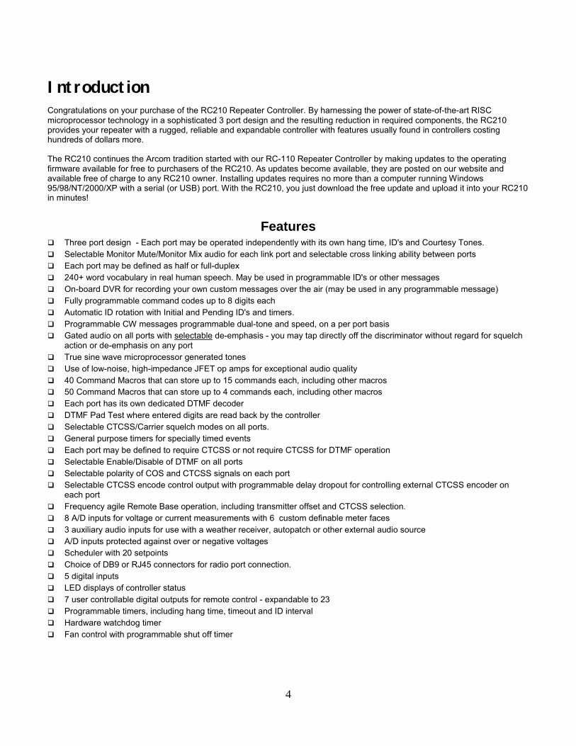
IntroductionCongratulations on your purchase of the RC210 Repeater Controller. By harnessing the power of state-of-the-art RISCmicroprocessor technology in a sophisticated 3 port design and the resulting reduction in required components, the RC210provides your repeater with a rugged, reliable and expandable controller with features usually found in controllers costinghundreds of dollars more.
The RC210 continues the Arcom tradition started with our RC-110 Repeater Controller by making updates to the operatingfirmware available for free to purchasers of the RC210. As updates become available, they are posted on our website andavailable free of charge to any RC210 owner. Installing updates requires no more than a computer running Windows95/98/NT/2000/XP with a serial (or USB) port. With the RC210, you just download the free update and upload it into your RC210in minutes!
Features! Three port design - Each port may be operated independently with its own hang time, ID's and Courtesy Tones.! Selectable Monitor Mute/Monitor Mix audio for each link port and selectable cross linking ability between ports! Each port may be defined as half or full-duplex! 240+ word vocabulary in real human speech. May be used in programmable ID's or other messages! On-board DVR for recording your own custom messages over the air (may be used in any programmable message)! Fully programmable command codes up to 8 digits each! Automatic ID rotation with Initial and Pending ID's and timers.! Programmable CW messages programmable dual-tone and speed, on a per port basis! Gated audio on all ports with selectable de-emphasis - you may tap directly off the discriminator without regard for squelch
action or de-emphasis on any port! True sine wave microprocessor generated tones! Use of low-noise, high-impedance JFET op amps for exceptional audio quality! 40 Command Macros that can store up to 15 commands each, including other macros! 50 Command Macros that can store up to 4 commands each, including other macros! Each port has its own dedicated DTMF decoder! DTMF Pad Test where entered digits are read back by the controller! Selectable CTCSS/Carrier squelch modes on all ports.! General purpose timers for specially timed events! Each port may be defined to require CTCSS or not require CTCSS for DTMF operation! Selectable Enable/Disable of DTMF on all ports! Selectable polarity of COS and CTCSS signals on each port! Selectable CTCSS encode control output with programmable delay dropout for controlling external CTCSS encoder on
each port! Frequency agile Remote Base operation, including transmitter offset and CTCSS selection.! 8 A/D inputs for voltage or current measurements with 6 custom definable meter faces! 3 auxiliary audio inputs for use with a weather receiver, autopatch or other external audio source! A/D inputs protected against over or negative voltages! Scheduler with 20 setpoints! Choice of DB9 or RJ45 connectors for radio port connection.! 5 digital inputs! LED displays of controller status! 7 user controllable digital outputs for remote control - expandable to 23! Programmable timers, including hang time, timeout and ID interval! Hardware watchdog timer! Fan control with programmable shut off timer

5
Description of Features
The RC210 provides 3 radio "ports", each of which may be operated independently or in unison with the others. With simpleprogramming, each port can be configured as follows:
A Standalone RepeaterA signal received on that port's receiver is retransmitted out that port's transmitter. Each port has its own independent hangtimer, timeout timer, 10 courtesy tones and dedicated DTMF decoder, so you may operate one RC210 to control 3 independentrepeaters. On command, any port may be tied to any other port for linking purposes.
Half-Duplex Or Full-Duplex LinkIf a port is configured as half-duplex, a signal received on that port's receiver is NOT retransmitted out that port's transmitter.Through DTMF commands, the receiver's COS (and CTCSS signal, if so equipped) and audio is routed to either - or both - ofthe other ports. This is useful for linking to other sites or connecting your system to an EchoLink©, IRLP© or other such system.
Control ReceiverBecause of the RC210's ability to control any Port from any other Port, there is no need for a special, dedicated control receiverport. By using the right combination of Macro Functions, you can easily and quickly disable or enable any function the RC210 iscapable of performing. For example, you have a repeater on Port 1 and a link on Port 2.
Remote BaseAny port can be used for a remote base - a half-duplex (or simplex) radio connected to the repeater system that allows therepeater users to remotely operate on a different frequency/mode/band than the repeater. Frequency, transmitter offset andCTCSS may all be remotely programmed over the air. The RC210 also supports control of Kenwood mobiles that provide forDTMF control through their microphone port. The complete list of supported remote base radios can be found in Appendix A.
Regardless of how you configured a port, each one provides all signals needed for the radio connected to it (COS, transmit anddiscriminator audio, CTCSS encode and decode). You have a choice of either DB9's or RJ45 modular jacks as your radio portconnector. COS and CTCSS decoder input polarity is selectable through easy-to-use push-pin jumper blocks, so the RC210 canaccommodate just about any radio available.
Audio gating is provided on each radio port so you may obtain audio directly from the receiver's discriminator without the worryof finding a source of gated audio in the receiver. De-emphasis is also provided on each port. However if you don't need de-emphasis on any particular port, it's a simple matter to change a jumper (no soldering required) and obtain "flat" audio (20 hz to15Khz) throughout the audio chain. The use of low-noise JFET operational amplifiers ensures good gain, high input impedance,and very clean audio.
DTMF tones are normally muted on ALL ports however you can turn off muting on a port-by-port basis. This allows for passingDTMF tones out a link.
Any port can be used for entering DTMF commands, even programming commands for other ports. Since each port has its own,dedicated DTMF decoder, a command can be entered from any port uninterrupted regardless of activity on other ports.
Many timers are provided, such as repeater transmitter hang time, timeout, ID intervals, how long the cooling fan should remainon after the transmitter unkeys, and more. These timers are remotely programmable.
The RC -210 incorporates true human speech. A custom, repeater oriented vocabulary is provided for use in IDs, alarm andother controller messages. In addition, the on-board digital voice recorder allows the recording of up to 20 custom recordingswhich may also be used in these messages.

6
All parameters of the controller can be remotely programmed using DTMF. Timers, control codes, port configuration andmessages can all be changed at the whim of the repeater owner. All the command codes may be programmed to your own,special and unique code. This makes the RC210 very easy to incorporate into existing systems without users having to relearncode structures. All parameters are stored in non-volatile EEPROM, so your settings are retained even if the controller losespower.
The controller's programming is protected from unauthorized access by the use of 3 different 5-digit secret passcodes - oneused for each port. Each port may be programmed independently without affecting the others.
The RC -210 represents all numbers in standard decimal notation. In other words, you don't need to worry about convertingprogramming parameters to hexadecimal notation before actually programming anything.
There are 7 buffered general-purpose digital outputs also provided that can be used to remotely control devices at the repeater.Alternately these outputs can be programmed to perform other tasks. With the addition of simple external shift registers, thesecan be expanded to 64 outputs.
The controller uses flash memory to store its operating program. Just plug your computer into the RC -210's programming portand you can upload updates in minutes.
A Word About IdentificationThe RC210 provides an intelligent algorithm for ID sequences to minimize disruption to ongoing repeater communications, whileproviding entertaining messages and meeting FCC requirements for repeater identification.
If the repeater has not been in use for a period of time and a new user keys the repeater, the controller will ID after he unkeyswith one of the three Initial ID messages (these messages automatically rotate). This message could say "Welcome" followed bythe callsign, or some other such "friendly" message.
After the Initial ID is finished, the Pending ID timer starts to run. After it times out, it looks to see if any repeater activity hasoccurred since the Initial ID played. If there has been activity and no user is currently talking, the Pending ID is played.Otherwise, the controller waits for no user and then will send the Pending ID message.
Specifications
Microprocessor: Atmel ATMega128 RISC processor running at 16 MhzProgram Memory: 128K Bytes - Flash EEPROMRunning Memory: 4K Bytes RAM, 4K Bytes EEPROMSpeech Method: ISD 4003 series VoiceCorder© ICLogic Inputs: Low < .8 volts
High: 5 volts maxAnalog Inputs: 0 - 5 vdc maximumLogic Outputs: 90v @ 500 ma open collectorAudio Inputs: High impedance >10KAudio Outputs: up to 6 volts p-pPower Requirement: 11.5 to 15V dc @ 60 ma.Operating Temp: -15 to +55 degrees C (5 to 150 degrees F)Board size: 9.0 x 5.2 inches (9.0 x 5.4 inches including connectors)Connectors: Phoenix 4 pin power connector (mating plug included with RC210)
DB-25 female for I/O and A/D. Radio ports are DB9 or RJ45
7
Hardware Reference
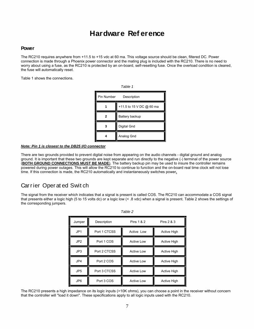
PowerThe RC210 requires anywhere from +11.5 to +15 vdc at 60 ma. This voltage source should be clean, filtered DC. Powerconnection is made through a Phoenix power connector and the mating plug is included with the RC210. There is no need toworry about using a fuse, as the RC210 is protected by an on-board, self-resetting fuse. Once the overload condition is cleared,the fuse will automatically reset.
Table 1 shows the connections.
Table 1
Pin Number Description
1 +11.5 to 15 V DC @ 60 ma
2 Battery backup
3 Digital Gnd
4 Analog Gnd
Note: Pin 1 is closest to the DB25 I/O connector
There are two grounds provided to prevent digital noise from appearing on the audio channels - digital ground and analogground. It is important that these two grounds are kept separate and run directly to the negative (-) terminal of the power source(BOTH GROUND CONNECTIONS MUST BE MADE). The battery backup pin may be used to insure the controller remainspowered during power outages. This will allow the RC210 to continue to function and the on-board real time clock will not losetime. If this connection is made, the RC210 automatically and instantaneously switches power.
Carrier Operated SwitchThe signal from the receiver which indicates that a signal is present is called COS. The RC210 can accommodate a COS signalthat presents either a logic high (5 to 15 volts dc) or a logic low (< .8 vdc) when a signal is present. Table 2 shows the settings ofthe corresponding jumpers.
Table 2
Jumper Description Pins 1 & 2 Pins 2 & 3
JP1 Port 1 CTCSS Active Low Active High
JP2 Port 1 COS Active Low Active High
JP3 Port 2 CTCSS Active Low Active High
JP4 Port 2 COS Active Low Active High
JP5 Port 3 CTCSS Active Low Active High
JP6 Port 3 COS Active Low Active High
The RC210 presents a high impedance on its logic inputs (>10K ohms), you can choose a point in the receiver without concernthat the controller will "load it down". These specifications apply to all logic inputs used with the RC210.
8
Sub-Audible Tone DecoderIn addition to the COS signal, the controller can optionally use a signal derived from an external CTCSS (continuous tonecontrolled squelch switch) decoder on each port. If this option is used, the controller can be commanded to require users to usesub-audible tone with their transmissions on that port. The RC210 accommodates either a logic high (5 to 15 vdc) or a logic low(< .8 v) when a valid tone is detected. This is set using the jumper settings, as shown in Table 2.
Push-To-TalkThe controller provides a solid-state switch closure to ground, capable of sinking 500 ma from a positive source at a voltage ofup to 100 vdc. This should accommodate just about any radio on the market.
Receiver Audio And De-EmphasisAudio from the receivers needs to be supplied to the controller and is controlled by a crosspoint switch matrix undermicroprocessor control. Each receiver's audio is routed to the appropriate transmitter(s) as needed.
The audio circuitry in the controller allows for a variety of signal levels and impedances. It is capacitively coupled, which meansthat a dc level may be present on the signal provided. The level is internally adjustable, so a fairly wide range of levels isacceptable, but for best results the level should be between .5 and 2.5 volts peak-to-peak. This should accommodate just aboutany receiver.
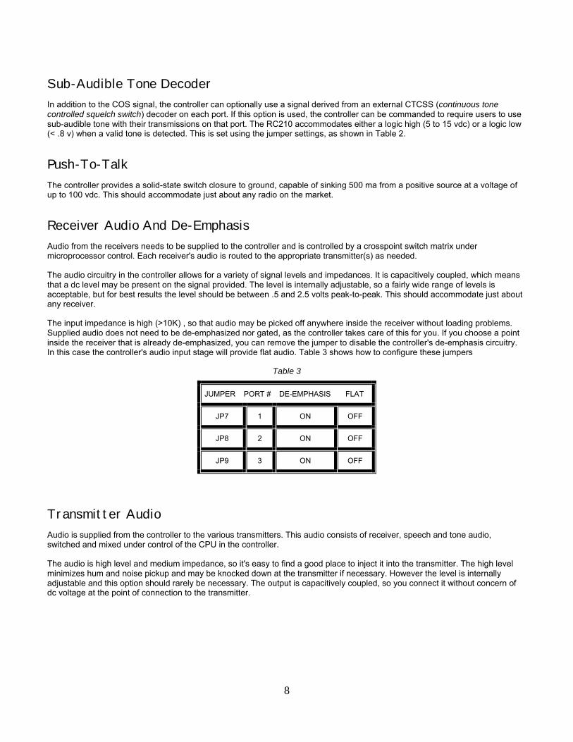
The input impedance is high (>10K) , so that audio may be picked off anywhere inside the receiver without loading problems.Supplied audio does not need to be de-emphasized nor gated, as the controller takes care of this for you. If you choose a pointinside the receiver that is already de-emphasized, you can remove the jumper to disable the controller's de-emphasis circuitry.In this case the controller's audio input stage will provide flat audio. Table 3 shows how to configure these jumpers
Table 3
JUMPER PORT # DE-EMPHASIS FLAT
JP7 1 ON OFF
JP8 2 ON OFF
JP9 3 ON OFF
Transmitter AudioAudio is supplied from the controller to the various transmitters. This audio consists of receiver, speech and tone audio,switched and mixed under control of the CPU in the controller.
The audio is high level and medium impedance, so it's easy to find a good place to inject it into the transmitter. The high levelminimizes hum and noise pickup and may be knocked down at the transmitter if necessary. However the level is internallyadjustable and this option should rarely be necessary. The output is capacitively coupled, so you connect it without concern ofdc voltage at the point of connection to the transmitter.

9
DTMF DecodersEach port has its own dedicated DTMF decoder, with each decoder being connected full time to its respective port. DTMF maybe entered at any time from any port without regard to activity on the other ports. The controller will store the commands and acton them in the order they were received. Each decoder may be configured to require CTCSS in order to function or not requireCTCSS.
Indicator LEDsLED's are provided for monitoring all the Port's COS, CTCSS, PTT and Valid DTMF signals. These can be useful for setting upand verifying operation of these various signals and are marked directly on the PC board. In order to reduce powerconsumption when the LEDs do not have to be powered up, the push-on jumper on JP13 may be removed. If mounting theRC210 in a cabinet, a switch may be connected to JP13 to allow the operator to conveniently turn the LEDs on and off asneeded.
Auxiliary Audio InputsThese inputs allow you to add external audio devices without using one of the radio ports. For example, you could connect aweather receiver to one and be able to monitor weather conditions on demand. If the weather receiver has an output that istriggered when a S.A.M.E. Alert is issued, you can use one of the Alarm inputs on the RC210 to automatically trigger one (or all)of the transmitters.
The Auxiliary Audio Inputs do not provide any means for adjusting their level, so you must provide this capability in yourinterface between your audio source and the RC210. The impedance of these inputs is approximately 20K and the level shouldbe adjusted to approximately 100 mv peak-to-peak.
Expansion ConnectorsThere are several pin header connectors on the PC board which allow for easy access to several data lines in the RC210.
J8 - DTMF EXPAND J7 - I/0 EXPAND J9 - AUDIO EXPAND
Pin 1 BCD Output Q1 Pin 1 Shift Register Data Pin 1 Digital Gnd
Pin 2 BCD Output Q2 Pin 2 Shift Register Clock Pin 2 Vcc (+5)
Pin 3 BCD Output Q4 Pin 3 Shift Register Latch Pin 3 Record input to ISD
Pin 4 BCD Output Q8 Pin 4 LED Serial Data Pin 4 Auxiliary Audio Input 3
Pin 5 Decoder Strobe Port 1 Pin5 LED Data Pin 5 Auxiliary Audio Input 2
Pin 6 Decoder Strobe Port 2 Pin 6 LED Clock Pin 6 Auxiliary Audio Input 1
Pin 7 Decoder Strobe Port 3 Pin 7 Vcc (+5 Vdc)
Pin 8 Decoder Select Port 1 Pin 8 Digital Ground
Pin 9 Decoder Select Port 2
Pin 10 Decoder Select Port 3
10
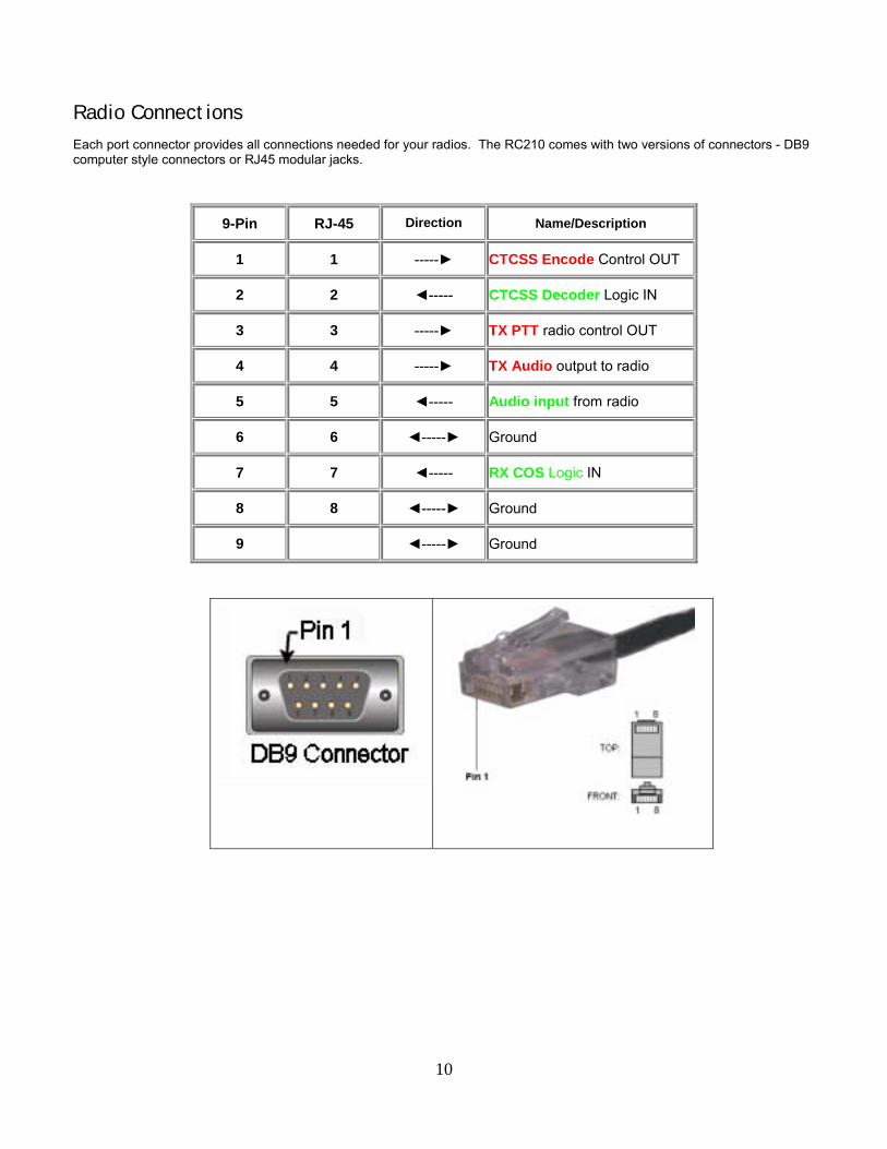
Radio ConnectionsEach port connector provides all connections needed for your radios. The RC210 comes with two versions of connectors - DB9computer style connectors or RJ45 modular jacks.
9-Pin RJ-45 Direction Name/Description
1 1 -----► CTCSS Encode Control OUT
2 2 ◄----- CTCSS Decoder Logic IN
3 3 -----► TX PTT radio control OUT
4 4 -----► TX Audio output to radio
5 5 ◄----- Audio input from radio
6 6 ◄-----► Ground
7 7 ◄----- RX COS Logic IN
8 8 ◄-----► Ground
9 ◄-----► Ground
11
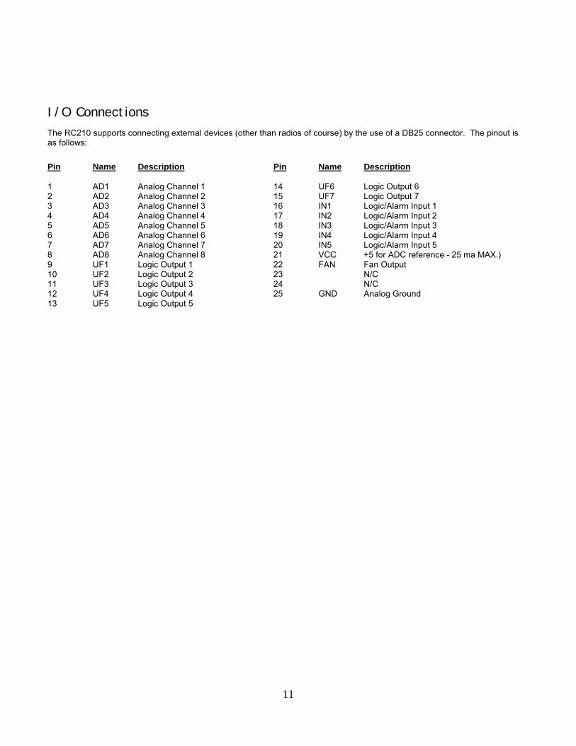
I/O ConnectionsThe RC210 supports connecting external devices (other than radios of course) by the use of a DB25 connector. The pinout isas follows:
Pin Name Description Pin Name Description
1 AD1 Analog Channel 1 14 UF6 Logic Output 62 AD2 Analog Channel 2 15 UF7 Logic Output 73 AD3 Analog Channel 3 16 IN1 Logic/Alarm Input 14 AD4 Analog Channel 4 17 IN2 Logic/Alarm Input 25 AD5 Analog Channel 5 18 IN3 Logic/Alarm Input 36 AD6 Analog Channel 6 19 IN4 Logic/Alarm Input 47 AD7 Analog Channel 7 20 IN5 Logic/Alarm Input 58 AD8 Analog Channel 8 21 VCC +5 for ADC reference - 25 ma MAX.)9 UF1 Logic Output 1 22 FAN Fan Output10 UF2 Logic Output 2 23 N/C11 UF3 Logic Output 3 24 N/C12 UF4 Logic Output 4 25 GND Analog Ground13 UF5 Logic Output 5

12
Analog InputsThe RC210 allows you to connect external analog devices and readback their value on command. This is typically used forremote monitoring of such things as backup battery voltage, transmitter power, etc. There are 8 "meters" corresponding to the 8Analog inputs. There are 6 meter faces you may define (this is explained in the Programming section) to any of these meters;the selection of which properly scales the reading as well as properly "announcing" the meterface when readback of the value isrequested.
VoltsAmpsWattsDegreesMPHPercent
NOTE: While these inputs are protected against reasonable overload conditions, care should nevertheless be taken never to apply avoltage that exceeds +5.2v or any voltage that is below ground (negative).
VoltageThe major task involved in using a meter face is to design a sensor circuit that generates a sensor voltage in the approximaterange of 0 to 5 Vdc that is linearly related to actual physical measurement, such as a 12 volt battery. A simple device tomeasure battery voltage would be a 10K potentiometer (pot). The actual voltages would be across the entire pot, and the sensorvoltage would be taken off the wiper. To adjust the pot correctly, it might be set to produce 2.5 volts output at the wiper when 20volts is put across the entire 10K. Since the typical battery used in a repeater is unlikely to produce 20 volts, this would be asafe �transducer� or sensor circuit for a typical 12 volt battery.
Or perhaps you'd like to monitor AC line voltage:
13
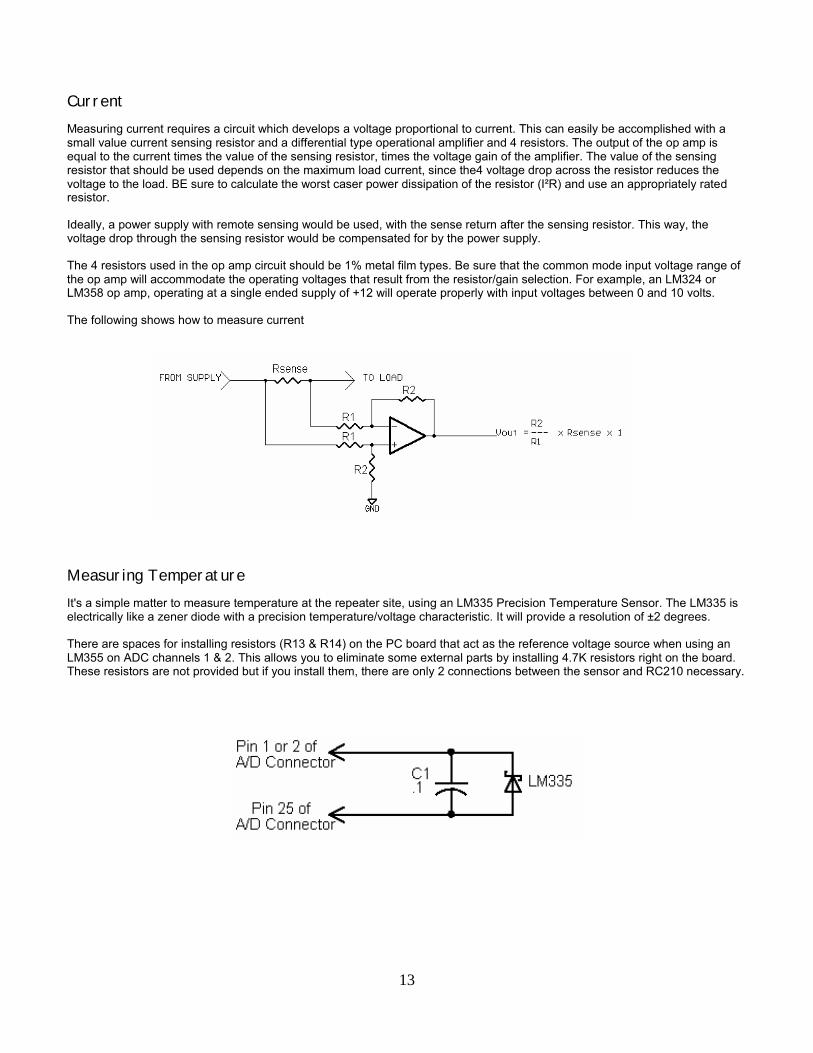
CurrentMeasuring current requires a circuit which develops a voltage proportional to current. This can easily be accomplished with asmall value current sensing resistor and a differential type operational amplifier and 4 resistors. The output of the op amp isequal to the current times the value of the sensing resistor, times the voltage gain of the amplifier. The value of the sensingresistor that should be used depends on the maximum load current, since the4 voltage drop across the resistor reduces thevoltage to the load. BE sure to calculate the worst caser power dissipation of the resistor (I²R) and use an appropriately ratedresistor.
Ideally, a power supply with remote sensing would be used, with the sense return after the sensing resistor. This way, thevoltage drop through the sensing resistor would be compensated for by the power supply.
The 4 resistors used in the op amp circuit should be 1% metal film types. Be sure that the common mode input voltage range ofthe op amp will accommodate the operating voltages that result from the resistor/gain selection. For example, an LM324 orLM358 op amp, operating at a single ended supply of +12 will operate properly with input voltages between 0 and 10 volts.
The following shows how to measure current
Measuring TemperatureIt's a simple matter to measure temperature at the repeater site, using an LM335 Precision Temperature Sensor. The LM335 iselectrically like a zener diode with a precision temperature/voltage characteristic. It will provide a resolution of ±2 degrees.
There are spaces for installing resistors (R13 & R14) on the PC board that act as the reference voltage source when using anLM355 on ADC channels 1 & 2. This allows you to eliminate some external parts by installing 4.7K resistors right on the board.These resistors are not provided but if you install them, there are only 2 connections between the sensor and RC210 necessary.

14
Measuring PowerPower is different than other types of measurements in that meter deflection is not linearly proportional to power level. The scaleis expanded out at the low end and "compressed" at the high end. This is due to the fact that power is proportional to voltage orcurrent squared (this is known as a logarithmic scale). The power meter face in the RC210 takes this into account when taking ameasurement.
Many watt meters provide a dc voltage output relational to forward and reflected power. In this example, we'll show how to usethese outputs to interface to the RC210.
Resistors are selected on the basis of the power level to be measured to provide 0 to 5 volt dc levels to the controller's analoginputs and should be adjusted for accurate reading at the normal power level.
AlarmsThe RC210 incorporates 5 alarm logic inputs that when used with the proper sensors, can monitor various things around therepeater site. For example, you could install a switch on the door to the building, so you'd know when someone opens the door.More details may be found in the Programming Reference section of this manual.
All logic inputs are triggered on a logic low (pulled to ground) and remain triggered until that Alarm is turned off. In other words, ifthe trigger signal is only momentary, the Alarm will remain triggered even though the input signal returns to its non-triggeredstate, until it is manually (or by a macro) turned off. More details may be found in the Command Reference section of thismanual.
WARNING: NEVER apply more than +5 volts to any logic input pin.

15
Logic OutputsThe RC210 provides 7 general purpose outputs (expandable to 32) that you can use to switch electronic devices on and off atyour repeater site. While these outputs are buffered by open collector transistors, care should be used so as not to exceed theirratings (90V dc @ 500 ma). If you're switching an inductive load, be sure to use a quenching diode across it. If you need morelogic outputs, you can connect external shift registers and obtain up to 32 outputs. Fig 1 shows how this can be accomplished.
Only some of the stages needed to recover those functions have to be used. Each shift register used adds 8 outputs. So if youonly need an additional 16 outputs (above and beyond the 7 "on-board" outputs), you only need add 2 stages. If you want alladditional 64, you'll need a total of 8 shift registers (74HC595). Remember that these outputs are logic level and cannot driveloads.
The outputs of the shift registers cannot drive outside devices directly. You will need some kind of driver in order to drive otherthan TTL level devices. When an output of the shift register is selected by command, that output goes to a logic high. A goodoption would be to use a ULN2003A Darlington array transistor array, which can drive up to half an amp (500 ma) load at avoltage of up to 90vdc.
Fan OutputThe controller also provides a switched fan output that can be used to control a cooling fan for the repeater transmitter. To avoidunnecessary wear and tear on the fan, the fan only comes on when any transmitter is keyed, and remains on for 1 to 60 minutesafter the last transmitter drops. The amount of time the fan remains on is selected in programming mode.
This output is not meant to drive a fan directly, but rather an external relay or driver transistor which is then used to drive the fan.Its signal is available on Pin 22 of J4, the I/0 connector. When active, the Fan Output is pulled to ground. This output is an opencollector therefore it will not source any voltage.
16
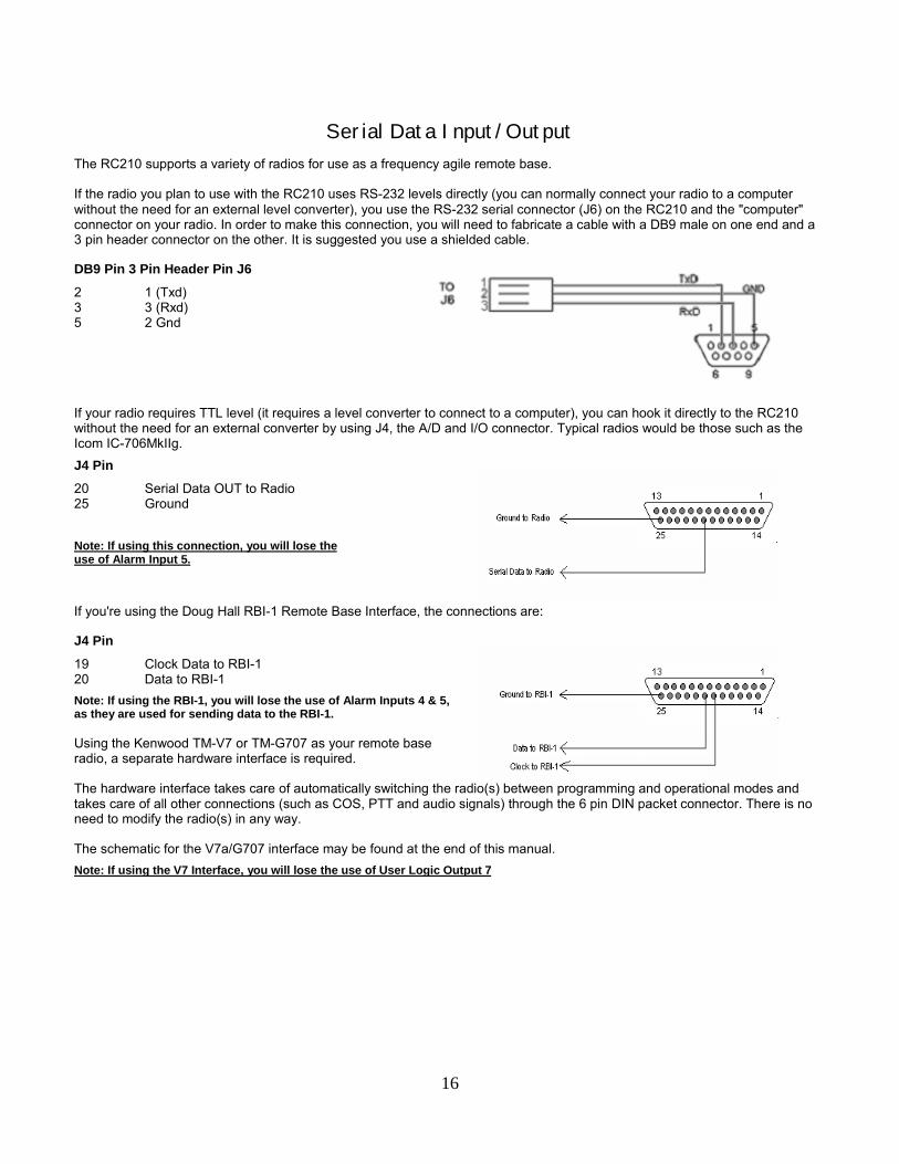
Serial Data Input/OutputThe RC210 supports a variety of radios for use as a frequency agile remote base.
If the radio you plan to use with the RC210 uses RS-232 levels directly (you can normally connect your radio to a computerwithout the need for an external level converter), you use the RS-232 serial connector (J6) on the RC210 and the "computer"connector on your radio. In order to make this connection, you will need to fabricate a cable with a DB9 male on one end and a3 pin header connector on the other. It is suggested you use a shielded cable.
DB9 Pin 3 Pin Header Pin J6
2 1 (Txd)3 3 (Rxd)5 2 Gnd
If your radio requires TTL level (it requires a level converter to connect to a computer), you can hook it directly to the RC210without the need for an external converter by using J4, the A/D and I/O connector. Typical radios would be those such as theIcom IC-706MkIIg.
J4 Pin
20 Serial Data OUT to Radio25 Ground
Note: If using this connection, you will lose theuse of Alarm Input 5.
If you're using the Doug Hall RBI-1 Remote Base Interface, the connections are:
J4 Pin
19 Clock Data to RBI-120 Data to RBI-1Note: If using the RBI-1, you will lose the use of Alarm Inputs 4 & 5,as they are used for sending data to the RBI-1.
Using the Kenwood TM-V7 or TM-G707 as your remote baseradio, a separate hardware interface is required.
The hardware interface takes care of automatically switching the radio(s) between programming and operational modes andtakes care of all other connections (such as COS, PTT and audio signals) through the 6 pin DIN packet connector. There is noneed to modify the radio(s) in any way.
The schematic for the V7a/G707 interface may be found at the end of this manual.Note: If using the V7 Interface, you will lose the use of User Logic Output 7

17
Figure 1
The RC210 supports the Kenwood single-band mobiles TM-271A (2 meters) and TM-471A (70 cm). Interfacing the necessaryserial connections is easy. See Figure 1 above
Note: If using this connection, you will lose the use of Alarm Input 5.
In addition to the above connections, you will also need to provide the audio, PTT, etc. signals as well.
Unfortunately, the A suffix models (the ones sold in the USA) do not have a packet jack already installed and the necessarysignals are not readily available from the mic jack. Fortunately however, Kenwood made these signals very easily accessible butit does require you open the radio in order to connect to them.
If you remove the cover of the radio, you will see gold plated pads near the power connections. These pads are normally used inthe E model (European) to connect a pigtail, which then provides the necessary signal access for packet use. These will supplythe needed connections (other than programming) to the RC210 for remote base use as well.
PAD NAME SIGNAL
PKS PTT (active low)SQC COS (active high of +5)PR9 Receive audio *PKD Transmit audio *
* The characteristics of both receive and transmit audio is determined by menu selection 39, which is normally used for packet.
In the 1200 baud mode:
PR9 provides 500 mv p-to-p, deemphasized and squelch gated audioPKD provides preemphasized transmit audio
In 9600 mode:
PR9 provides 500 mv p-to-p, non-deemphasized and non-gated discriminator audioPKD provides non-emphasized transmit audio

18
Audio Delay Expansion HeadersAudio from the receiver buffers is routed through pin header connectors on the PC board to allow connection of the Arcomrepeater audio delay (RAD) board. This board provides an audio delay of approx. 60 ms, which removes DTMF bursts andsquelch tail crashes from the transmitted audio. If the board is not connected, there must be jumpers in place between pins (pins2 & 3) of JP10, JP11 and JP12 to complete the audio path from receivers to the crosspoint switch.
Checking COS And PTT OperationOnce connections are made, the next step is to verify that COS and PTT are operating properly. There are a series of LED's onthe RC210 that are used to indicate the status of various functions. Their function is marked on the PC board. They may beturned off to save power when you don't need them by removing the jumper from JP13. By observing the LED's, you can easilyverify COS, PTT, CTCSS and DTMF operation.
Setting Audio LevelsRefer to the PCB layout at the end of this manual while making adjustments. If you do not have a signal generator oroscilloscope, you might want to explore the use of a Sound Card based Audio Spectrum Analyzer program available fromInterFlex Systems Design Corporation. It can be helpful to measure audio levels, look for distortion, twist in the DTMF tones, etc.
Using a signal generator, generate a signal on the receiver's frequency with 1000 Hz modulation @ 3 Khz deviation. Keep inmind that for best quality audio and to avoid clipping, we want the minimum amount of amplification necessary. An oscilloscopeshould be used to measure the voltage. Following the Table 5, adjust the appropriate trimpot for a level of .75 volt peak-to-peakat the corresponding test point.
Table 5
PORT TRIMPOT TESTPOINT
1 "Port1 Disc" TP1
2 "Port2 Disc" TP2
3 "Port3 Disc" TP3
Once the receiver levels are adjusted, it's time to adjust the transmitter audio levels. While still generating a signal on thereceiver frequency, adjust the corresponding trimpot for +/- 3 Khz of the appropriate transmitter.
Table 6
PORT TRIMPOT
1 "P1 Tx"
2 "P2 Tx"
3 "P3 Tx"
Using a radio equipped with a DTMF pad, transmit on the receiver frequency and while transmitting a DTMF tone (it issuggested you use either a "3" or a "5" for this adjustment, as these are the most difficult tones to decode. The correspondingLED should light with every DTMF key press.

19
Note: If you don't have access to test equipment, you can temporarily adjust the receiver buffer trimpots to the midpoint and adjust thetransmit trimpots so the repeated audio "sounds the same" as does your radio when transmitting direct. But be sure to set these levels withthe proper test equipment before deploying your repeater!
The Tone trimpot adjusts the level of courtesy tones and CW ID's. You should adjust it for +/- 3 Khz deviation.
The Play trimpot adjusts the level of the output of the speech chip. You can adjust this for a comfortable level while thecontroller is speaking (you can enter a command that causes the controller to speak in order to adjust this level).
Note: If you have set the discriminator and transmit audio levels correctly, the levels of tones and speech should be identical on all 3ports.
ARCOM COMMUNICATIONS NO-NONSENSE LICENSEAGREEMENT FOR THE OPERATING FIRMWARE OF THE
RC210 REPEATER CONTROLLERIMPORTANT - READ CAREFULLY
This license statement and limited warranty constitutes a legal agreement ("License Agreement") between you (either as anindividual or a single entity) and Arcom Communications for the software product ("Firmware") identified above, including anysoftware, media, and accompanying on-line or printed documentation.
BY DOWNLOADING OR OTHERWISE USING THE FIRMWARE, YOU AGREE TO BE BOUND BY ALL OF THE TERMS ANDCONDITIONS OF THIS LICENSE AGREEMENT.
Upon your acceptance of the terms and conditions of the License Agreement, Arcom Communications grants you the right touse the Firmware in the manner provided below.
This Firmware is owned by Arcom Communications and is protected by copyright law and international copyrighttreaty. Therefore, you must treat this Firmware like any other copyrighted material (e.g., a book), except that youmay either make copies of the Firmware solely for backup or archival purposes or transfer the Firmware to a singlehard disk provided you keep the original solely for backup or archival purposes.
You may transfer the Firmware and documentation on a permanent basis provided you retain no copies and therecipient agrees to the terms of this License Agreement. Except as provided in this License Agreement, you may nottransfer, rent, lease, lend, copy, modify, translate, sublicense, time-share or electronically transmit orreceive the Firmware, media or documentation.
TO THE MAXIMUM EXTENT PERMITTED BY APPLICABLE LAW, ARCOM COMMUNICATIONS DISCLAIM ALL OTHERWARRANTIES AND CONDITIONS, EITHER EXPRESS OR IMPLIED, INCLUDING, BUT NOT LIMITED TO, IMPLIEDWARRANTIES OF MERCHANTABILITY, FITNESS FOR A PARTICULAR PURPOSE, TITLE, AND NON-INFRINGEMENT,WITH REGARD TO THE FIRMWARE, AND THE PROVISION OF OR FAILURE TO PROVIDE SUPPORT SERVICES. THISLIMITED WARRANTY GIVES YOU SPECIFIC LEGAL RIGHTS. YOU MAY HAVE OTHERS, WHICH VARY FROMSTATE/JURISDICTION TO STATE/JURISDICTION.
LIMITATION OF LIABILITY TO THE MAXIMUM EXTENT PERMITTED BY APPLICABLE LAW, IN NO EVENT SHALL ARCOMCOMMUNICATIONS OR ITS SUPPLIERS BE LIABLE FOR ANY SPECIAL, INCIDENTAL, INDIRECT, OR CONSEQUENTIALDAMAGES WHATSOEVER (INCLUDING, WITHOUT LIMITATION, DAMAGES FOR LOSS OF BUSINESS PROFITS,BUSINESS INTERRUPTION, LOSS OF BUSINESS INFORMATION, OR ANY OTHER PECUNIARY LOSS) ARISING OUT OFTHE USE OF THE FIRMWARE OR INABILITY TO USE THE FIRMWARE PRODUCT OR THE PROVISION OF OR FAILURETO PROVIDE SUPPORT SERVICES, EVEN IF ARCOM COMMUNICATIONS HAS BEEN ADVISED OF THE POSSIBILITY OFSUCH DAMAGES.


21
PC Board ComponentPlacement

22

23

24