
RC-1604 - Remanufacturing, Repurposing, and … · REPORT 12-20 REMANUFACTURING, REPURPOSING, ......
70
A publication of Mineta National Transit Research Consortium College of Business San José State University San José, CA 95192-0219 REPORT 12-20 REMANUFACTURING, REPURPOSING, AND RECYCLING OF POST-VEHICLE-APPLICATION LITHIUM-ION BATTERIES Charles R. Standridge, Ph.D. Lindsay Corneal, Ph.D. June 2014
Transcript of RC-1604 - Remanufacturing, Repurposing, and … · REPORT 12-20 REMANUFACTURING, REPURPOSING, ......

A publication of
Mineta National Transit Research ConsortiumCollege of BusinessSan José State UniversitySan José, CA 95192-0219
REPORT 12-20
REMANUFACTURING, REPURPOSING, AND RECYCLING OF POST-VEHICLE-APPLICATION
LITHIUM-ION BATTERIES
Charles R. Standridge, Ph.D.Lindsay Corneal, Ph.D.
June 2014

TECHNICAL REPORT DOCUMENTATION PAGE
1. Report No. 2. Government Accession No. 3. Recipient’s Catalog No.
4. Title and Subtitle 5. Report Date
6. Performing Organization Code
7. Authors 8. Performing Organization Report
9. Performing Organization Name and Address 10. Work Unit No.
11. Contract or Grant No.
12. Sponsoring Agency Name and Address 13. Type of Report and Period Covered
14. Sponsoring Agency Code
15. Supplemental Notes
16. Abstract
17. Key Words 18. Distribution Statement
19. Security Classif. (of this report) 20. Security Classif. (of this page) 21. No. of Pages 22. Price
Form DOT F 1700.7 (8-72)
58
CA-MNTRC-14-1137
Remanufacturing, Repurposing, and Recycling of Post-Vehicle-Application Lithium-Ion Batteries
June 2014
MNTRC Report 12-20Charles R. Standridge, Ph.D. and Lindsay Corneal, Ph.D.
Mineta National Transit Research ConsortiumCollege of Business San José State University San José, CA 95192-0219
U.S. Department of TransportationResearch & Innovative Technology Admin.1200 New Jersey Avenue, SEWashington, DC 20590
Final Report
UnclassifiedUnclassified
No restrictions. This document is available to the public through The National Technical Information Service, Springfield, VA 22161
DTRT12-G-UTC21
$15.00
As lithium-ion batteries are an efficient energy storage mechanism, their use in vehicles is increasing to support electrification to meet increasing average mileage and decreasing greenhouse gas emission standards. Principles of environmentalism and sustainability suggest the development of processes for the remanufacturing, repurposing, and recycling of post-vehicle-application lithium-ion batteries. Proprietary commercial processes for remanufacturing for reuse in vehicles require safe battery testing that is supported by a newly developed workbench. Repurposing, with a focus on stationary energy storage applications and the development of battery management systems, is demonstrated. Recycling to recover the battery component materials using manual disassembly and acid leaching at relatively low temperatures and in short time periods is shown to be effective. A cost benefit-analysis shows that remanufacturing is profitable. Repurposing is profitable if the development cost is no more than $83/kWh to $114/kWh, depending on research and development expenses. Recycling, driven by environmental and sustainability principles, is not profitable in isolation. The cost of recycling must be borne by remanufacturing and repurposing. A forecasting model shows that the number of post-vehicle-application lithium-ion batteries will be sufficient to support remanufacturing, repurposing, and recycling.

To order this publication, please contact:
Mineta National Transit Research Consortium College of Business
San José State University San José, CA 95192-0219
Tel: (408) 924-7560 Fax: (408) 924-7565
Email: [email protected]
transweb.sjsu.edu/mntrc/index.html
by Mineta National Transit Research Consortium All rights reserved
Library of Congress Catalog Card Number:
Copyright © 2014
XXXXXXXXXXXX
061014

Mineta Nat ional Transi t Research Consort ium
iv

Mineta Nat ional Transi t Research Consort ium
v
ACKNOWLEDGMENTS
The work described in this report was sponsored by the Mineta National Transit Research Consortium and the US DOT Research Innovative Technology Administration with matching funds provided by the Michigan Department of Transportation, A123 Systems, and Grand Valley State University (GVSU). This sponsorship is gratefully acknowledged.
Sybesma’s Electronics of Holland, Michigan, participated as a full partner. This work would not have been possible without the support and personal involvement of Hank Sybesma, President of Sybesma’s Electronics.
Meaghan Foster, now of the Stephen Foster CPA firm in Stevensville, Michigan, led the development of the forecasting and economic analysis facet of this work while she was a student in the Masters in Accounting program at GVSU. She was supported by Professor Paul Isely, chair of the Economics Department at GVSU, and assisted by Mehedi Hasan, a student in the Master of Science in Engineering program at GVSU.
The remanufacturing portion of the project was led by Matt Barnaby, a co-op student in the Bachelor of Science in Engineering program at GVSU. He worked in close cooperation with Hank Sybesma to enhance the proprietary work of Sybesma’s Electronics. The primary result of this effort was a workbench for testing lithium-ion batteries safely.
Todd Alexander, a student in the Master of Science in Engineering program at GVSU, completed a repurposing demonstration for his capstone project under the supervision of Professor Lindsay Corneal of the School of Engineering. A design for a second, more complex repurposing demonstration was completed by Josh Zantello, a co-op student in the Bachelor of Science in Engineering program at GVSU.
The recycling component was led by Professor Lindsay Corneal and Eric Li, a student in the Master of Science in Engineering Program at GVSU. Their work has demonstrated a recycling process able to separate lithium-ion cells into component materials in a relatively benign environment: low temperatures, low concentrations of acid, in short time periods.
Background material concerning lithium-ion batteries was gathered as a part of a companion project – Lithium Ion Batteries: Recycling and Repurposing –sponsored by the Center for Advanced Automotive Technology at Macomb Community College. The contributions of the faculty of Muskegon Community College, Charles Ammond and Greg Marczak, are appreciated.
The authors also thank MTI staff, including Deputy Executive Director and Research Director Karen Philbrick, Ph.D.; Director of Communications and Technology Transfer Donna Maurillo; Research Support Manager Joseph Mercado; and Webmaster Frances Cherman. Additional editorial and publication support was provided by Editorial Associate Nancy Hannaford.

Mineta Nat ional Transi t Research Consort ium
vi Acknowledgments

Mineta Nat ional Transi t Research Consort ium
vii
TABLE OF CONTENTS
Executive Summary 1
I. Introduction 3
II. Availability of After Vehicle Life Batteries 5
III. Cost-Benefit Analysis 11Remanufacturing 11Repurposing 13Recycling 15
IV. Remanufacturing 19
V. Repurposing 23Energy Storage System Concept Demonstration 23Mobile Recycling Platform Design 30
VI. Recycling 33Safety and Precautions 33Battery Disassembly 34Material Extraction 35Results and Discussion 38
VII. Summary and Conclusion 41
Abbreviations and Acronyms 45
Endnotes 47
Bibliography 51
About the Authors 55
Peer Review 57

Mineta Nat ional Transi t Research Consort ium
viii Table of Contents

Mineta Nat ional Transi t Research Consort ium
ix
LIST OF FIGURES
1. Electric Vehicle Demand Forecast, 2010-2050 6
2. Plug-in Hybrid Electric Vehicle Demand Forecasts, 2010-2050 6
3. Post-Vehicle-Application Battery Forecasting Model 7
4. Optimistic View of the Number of Available Post-Vehicle-Application Batteries, 2010-2050 8
5. Middle View of the Number of Available Post-Vehicle-Application Batteries, 2010-2050 8
6. Pessimistic View of the Number of Available Post-Vehicle-Application Batteries, 2010-2050 9
7. Fail-Safe Workbench for Battery Testing 20
8. Self-Sealing Container for Battery 21
9. Mobile Energy Storage Unit, as Designed 24
10. Mobile Energy Storage Unit, as Assembled 25
11. Balancing of Cells in Battery 1 27
12. Battery 1 Voltage over Time 28
13. Battery Pack Assembly Voltage over Time 29
14. Mobile Recycling Platform (MRP) Layout 30
15. MRP Energy Storage System (ESS) Schematic 31
16. Layout of a Disassembled LiFePO4 Cell with an Unopened Cell 35

Mineta Nat ional Transi t Research Consort ium
x List of Figures
Mineta Nat ional Transi t Research Consort ium
xi
LIST OF TABLES
1. Cost-Benefit Analysis per Battery for Remanufacturing 13
2. Cost-Benefit Analysis per Battery for Repurposing 15
3. Cost-Benefit Analysis per Battery for Recycling 17
4. MRP Power Requirements 32
5. Material Separation and Extraction Tests with Aluminum and Copper Foil Using H2SO4, HNO3, and NMP 37
6. Material Preparation and Extraction Tests with Excessive Aluminum and Copper Foil 38
7. Reactions for Gas Collection Tests 38

Mineta Nat ional Transi t Research Consort ium
xii List of Tables
Mineta Nat ional Transi t Research Consort ium
1
EXECUTIVE SUMMARY
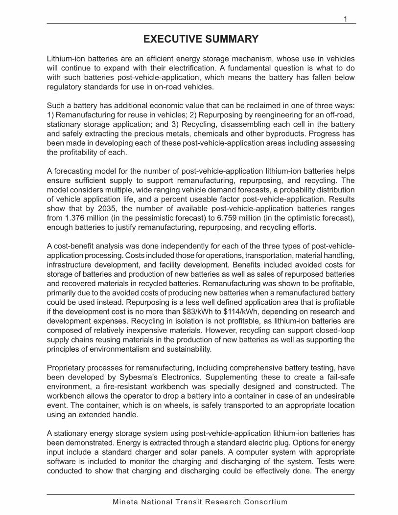
Lithium-ion batteries are an efficient energy storage mechanism, whose use in vehicles will continue to expand with their electrification. A fundamental question is what to do with such batteries post-vehicle-application, which means the battery has fallen below regulatory standards for use in on-road vehicles.
Such a battery has additional economic value that can be reclaimed in one of three ways: 1) Remanufacturing for reuse in vehicles; 2) Repurposing by reengineering for an off-road, stationary storage application; and 3) Recycling, disassembling each cell in the battery and safely extracting the precious metals, chemicals and other byproducts. Progress has been made in developing each of these post-vehicle-application areas including assessing the profitability of each.
A forecasting model for the number of post-vehicle-application lithium-ion batteries helps ensure sufficient supply to support remanufacturing, repurposing, and recycling. The model considers multiple, wide ranging vehicle demand forecasts, a probability distribution of vehicle application life, and a percent useable factor post-vehicle-application. Results show that by 2035, the number of available post-vehicle-application batteries ranges from 1.376 million (in the pessimistic forecast) to 6.759 million (in the optimistic forecast), enough batteries to justify remanufacturing, repurposing, and recycling efforts.
A cost-benefit analysis was done independently for each of the three types of post-vehicle-application processing. Costs included those for operations, transportation, material handling, infrastructure development, and facility development. Benefits included avoided costs for storage of batteries and production of new batteries as well as sales of repurposed batteries and recovered materials in recycled batteries. Remanufacturing was shown to be profitable, primarily due to the avoided costs of producing new batteries when a remanufactured battery could be used instead. Repurposing is a less well defined application area that is profitable if the development cost is no more than $83/kWh to $114/kWh, depending on research and development expenses. Recycling in isolation is not profitable, as lithium-ion batteries are composed of relatively inexpensive materials. However, recycling can support closed-loop supply chains reusing materials in the production of new batteries as well as supporting the principles of environmentalism and sustainability.
Proprietary processes for remanufacturing, including comprehensive battery testing, have been developed by Sybesma’s Electronics. Supplementing these to create a fail-safe environment, a fire-resistant workbench was specially designed and constructed. The workbench allows the operator to drop a battery into a container in case of an undesirable event. The container, which is on wheels, is safely transported to an appropriate location using an extended handle.
A stationary energy storage system using post-vehicle-application lithium-ion batteries has been demonstrated. Energy is extracted through a standard electric plug. Options for energy input include a standard charger and solar panels. A computer system with appropriate software is included to monitor the charging and discharging of the system. Tests were conducted to show that charging and discharging could be effectively done. The energy

Mineta Nat ional Transi t Research Consort ium
2 Executive Summary
storage system consists of two batteries known to have similar state-of-life characteristics. The original equipment manufacturer provided a battery management system.
A second, more realistic scale repurposing application, an energy storage system for a semi-mobile recycling platform to create an off-grid site for recycled goods, has been designed and is currently under development. Energy to power the storage system will be collected by solar panels. The amount of goods is monitored for retrieval as needed instead of on a predetermined schedule. The energy storage system supports cameras for monitoring, flood lights for site illumination, tube lights for internal platform illumination, a digital video recorder, and cell phones for transmission of monitoring information. A battery management system will be developed.
Recycling demonstration efforts focused on cleanly separating, and thus recovering, copper, aluminum and lithium iron phosphate from batteries. Laboratory-scale experiments were designed and conducted based on a review of previous studies concerning lithium cobalt oxide batteries. Acid leaching was identified as the most popular method for extracting raw materials from lithium cobalt oxide batteries. Disassembly demonstration equipment included a glove box with fume hood and air pump, a utility knife, and a sheet metal cutter. The cylindrical lithium iron phosphate batteries of interest have four layers within the jelly roll that comprises the cell beneath the outer cover: aluminum foil coated with lithium iron phosphate, copper foil coated with graphite, and the other two separator membranes with electrolyte residue on them. At the center of the jelly roll is a metallic tube, made of stainless steel. Material extraction means separating the coatings from the copper and aluminum foils. Acid leaching using nitric acid for aluminum and sulfuric acid for copper both at relatively low concentrations was successful at separating the coatings and the foil. The experiments were conducted at various temperatures ranging from 33°C to 60°C. The material was exposed to the acid for either one or two minutes.
Mineta Nat ional Transi t Research Consort ium
3
I. INTRODUCTION
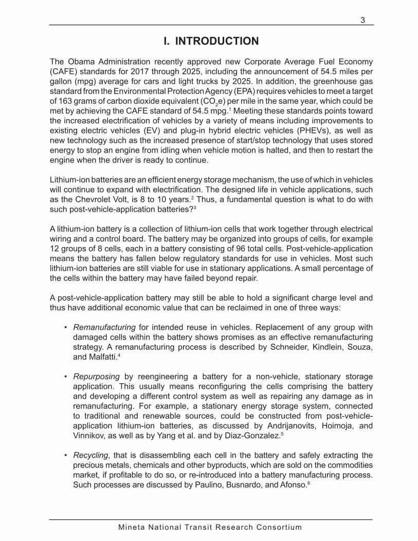
The Obama Administration recently approved new Corporate Average Fuel Economy (CAFE) standards for 2017 through 2025, including the announcement of 54.5 miles per gallon (mpg) average for cars and light trucks by 2025. In addition, the greenhouse gas standard from the Environmental Protection Agency (EPA) requires vehicles to meet a target of 163 grams of carbon dioxide equivalent (CO2e) per mile in the same year, which could be met by achieving the CAFE standard of 54.5 mpg.1 Meeting these standards points toward the increased electrification of vehicles by a variety of means including improvements to existing electric vehicles (EV) and plug-in hybrid electric vehicles (PHEVs), as well as new technology such as the increased presence of start/stop technology that uses stored energy to stop an engine from idling when vehicle motion is halted, and then to restart the engine when the driver is ready to continue.
Lithium-ion batteries are an efficient energy storage mechanism, the use of which in vehicles will continue to expand with electrification. The designed life in vehicle applications, such as the Chevrolet Volt, is 8 to 10 years.2 Thus, a fundamental question is what to do with such post-vehicle-application batteries?3
A lithium-ion battery is a collection of lithium-ion cells that work together through electrical wiring and a control board. The battery may be organized into groups of cells, for example 12 groups of 8 cells, each in a battery consisting of 96 total cells. Post-vehicle-application means the battery has fallen below regulatory standards for use in vehicles. Most such lithium-ion batteries are still viable for use in stationary applications. A small percentage of the cells within the battery may have failed beyond repair.
A post-vehicle-application battery may still be able to hold a significant charge level and thus have additional economic value that can be reclaimed in one of three ways:
• Remanufacturing for intended reuse in vehicles. Replacement of any group with damaged cells within the battery shows promises as an effective remanufacturing strategy. A remanufacturing process is described by Schneider, Kindlein, Souza, and Malfatti.4
• Repurposing by reengineering a battery for a non-vehicle, stationary storage application. This usually means reconfiguring the cells comprising the battery and developing a different control system as well as repairing any damage as in remanufacturing. For example, a stationary energy storage system, connected to traditional and renewable sources, could be constructed from post-vehicle- application lithium-ion batteries, as discussed by Andrijanovits, Hoimoja, and Vinnikov, as well as by Yang et al. and by Diaz-Gonzalez.5
• Recycling, that is disassembling each cell in the battery and safely extracting the precious metals, chemicals and other byproducts, which are sold on the commodities market, if profitable to do so, or re-introduced into a battery manufacturing process. Such processes are discussed by Paulino, Busnardo, and Afonso.6

Mineta Nat ional Transi t Research Consort ium
4 Introduction
This exploratory study involves identifying and bridging the gaps in remanufacturing, repurposing, and recycling technology. The progress made in each area is discussed in turn.
Equally important is an initial assessment of the profitability of remanufacturing, repurposing, and recycling. While these three activities seem technologically possible and necessary based on the principles of sustainability, they can only be effectively pursued if shown to be profitable. This includes developing an understanding of the number of post-vehicle-application batteries available for processing. A forecast is developed in this regard.

Mineta Nat ional Transi t Research Consort ium
5
II. AVAILABILITY OF AFTER VEHICLE LIFE BATTERIES
The number of post-vehicle-application lithium-ion batteries available over time can be estimated from forecasts of the numbers of EVs and PHEVs projected to be sold over time. Multiple previously existing such forecasts encompass a wide range. This is reflective of the challenges of creating a market for EVs and PHEVs, and consequently lithium-ion batteries.7 These multiple forecasts are organized into three categories:
1. A pessimistic view of future demand based on the Energy Information Administration’s (EIA) statistical analysis of future vehicle demand.8
2. An optimistic view of future demand based on the IEA future EV and PHEV report.9
3. A middle view, computed as the mathematical average of three independent industrial forecasts. The industrial forecasts seem reasonable as they are within the upper and lower bounds created by the public forecasts in items 1 and 2.
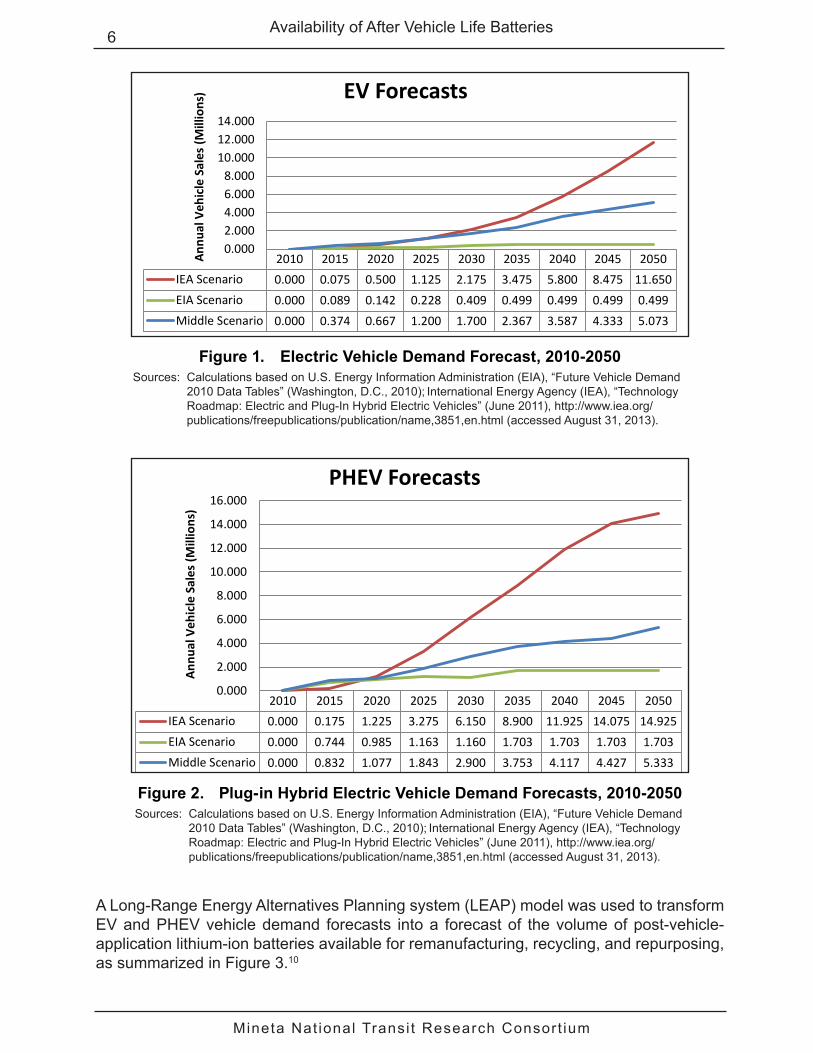
Figure 1 shows the three forecasts for EVs and Figure 2 shows these forecasts for PHEVs, with the pessimistic view represented by a green line, the optimistic view by a red line, and the middle view by a blue line. Assumptions concerning these forecasts are:
• The EIA (pessimistic view) forecast ends at 2035. No growth after 2035 was assumed.
• The demand for PHEV vehicles in 2010 was so small that it can be considered to be zero.
• The optimistic forecast is a fraction of the IEA forecast, which appears to contain an inconsistency. About 120 million vehicles in total sales per year is projected for 2050, but the report also states that 55% of that amount is just short of 120 million vehicles. Thus, this projection appears to be overestimated by nearly 50%. Reducing the forecast by 50% to account for this apparent inconsistency still results in a very high upper bound. This is explained by the IEA report not accounting for full market saturation of vehicles. To adjust for this omission and obtain a usable upper bound, an additional 50% reduction was applied resulting in an optimistic forecast of 25% of the original IEA forecast.
• Manufacturing of new EV and PHEV vehicles will expand to meet demand.
Mineta Nat ional Transi t Research Consort ium
6 Availability of After Vehicle Life Batteries
2010 2015 2020 2025 2030 2035 2040 2045 2050IEA Scenario 0.000 0.075 0.500 1.125 2.175 3.475 5.800 8.475 11.650EIA Scenario 0.000 0.089 0.142 0.228 0.409 0.499 0.499 0.499 0.499Middle Scenario 0.000 0.374 0.667 1.200 1.700 2.367 3.587 4.333 5.073
0.0002.0004.0006.0008.000
10.00012.00014.000
Annu
al V
ehic
le S
ales
(Mill
ions
) EV Forecasts
Figure 1. Electric Vehicle Demand Forecast, 2010-2050Sources: Calculations based on U.S. Energy Information Administration (EIA), “Future Vehicle Demand
2010 Data Tables” (Washington, D.C., 2010); International Energy Agency (IEA), “Technology Roadmap: Electric and Plug-In Hybrid Electric Vehicles” (June 2011), http://www.iea.org/publications/freepublications/publication/name,3851,en.html (accessed August 31, 2013).
2010 2015 2020 2025 2030 2035 2040 2045 2050IEA Scenario 0.000 0.175 1.225 3.275 6.150 8.900 11.925 14.075 14.925EIA Scenario 0.000 0.744 0.985 1.163 1.160 1.703 1.703 1.703 1.703Middle Scenario 0.000 0.832 1.077 1.843 2.900 3.753 4.117 4.427 5.333
0.000
2.000
4.000
6.000
8.000
10.000
12.000
14.000
16.000
Ann
ual V
ehic
le S
ales
(Mill
ions
)
PHEV Forecasts
Figure 2. Plug-in Hybrid Electric Vehicle Demand Forecasts, 2010-2050Sources: Calculations based on U.S. Energy Information Administration (EIA), “Future Vehicle Demand
2010 Data Tables” (Washington, D.C., 2010); International Energy Agency (IEA), “Technology Roadmap: Electric and Plug-In Hybrid Electric Vehicles” (June 2011), http://www.iea.org/publications/freepublications/publication/name,3851,en.html (accessed August 31, 2013).
A Long-Range Energy Alternatives Planning system (LEAP) model was used to transform EV and PHEV vehicle demand forecasts into a forecast of the volume of post-vehicle-application lithium-ion batteries available for remanufacturing, recycling, and repurposing, as summarized in Figure 3.10

Mineta Nat ional Transi t Research Consort ium
7Availability of After Vehicle Life Batteries
Figure 3. Post-Vehicle-Application Battery Forecasting Model
Source: Authors’ diagram.
The model considers that 85% of the batteries are reusable in post-vehicle-applications and that the remaining 15% are damaged beyond repair.11
Battery vehicle application life is modeled as uniformly distributed between 3 and 10 years. The maximum value is based on design specifications of 8 to 10 years of application life.12 Such batteries have been in use an insufficient time for experience to confirm the frequency with which the maximum duration of vehicle application can be reached. We have observed the duration to be as little as 3 years in some cases. As no other information on battery life is currently available, modeling this quantity as uniformly distributed is appropriate, as only the minimum and maximum can be estimated.
From this input, the supply of post-vehicle-application lithium-ion batteries available for remanufacturing, repurposing, and recycling is forecast. Results are shown for the optimistic, pessimistic, and middle vehicle demand forecasts in Figure 4, Figure 5, and Figure 6. In 2035, the number of available post-vehicle-application batteries ranges from 1.376 million in the pessimistic forecast to 6.759 million in the optimistic forecast, with a middle forecast of 3.773 million, enough batteries to justify remanufacturing, repurposing, and recycling efforts. More importantly, the number of available post-vehicle-application life batteries is between approximately 55% and 60% of the number of batteries needed for new EV and PHEV production, further supporting the opportunity for remanufacturing. In 2050, this range is approximately 70% to 85%, showing a growing opportunity for remanufacturing.

Mineta Nat ional Transi t Research Consort ium
8 Availability of After Vehicle Life Batteries
2.22 3.67
4.82 6.76
8.83
11.14
13.67
16.26
18.66
0.84 1.72
3.33 5.19
7.54
9.95
12.38
15.59
18.69
21.59
24.16
26.58
0
5
10
15
20
25
30
2010
2013
2016
2019
2022
2025
2028
2031
2034
2037
2040
2043
2046
2049
Num
ber o
f Bat
terie
s (M
illio
ns) End of Life Batteries: Optimistic View
Available EOLBatteries YearDemand Total
Figure 4. Optimistic View of the Number of Available Post-Vehicle- Application Batteries, 2010-2050
Source: International Energy Agency (IEA), “Technology Roadmap: Electric and Plug-In Hybrid Electric Vehicles” (June 2011); Available EOL Batteries/Year derived from model in Figure 3.
0.99 1.39
1.86 2.51
3.00 3.77
4.56 5.34
6.11 6.78
7.43
0.97 1.42 1.74
2.52 3.35
4.29
5.21 6.12
7.07 7.91
8.55 9.42
10.41
0
2
4
6
8
10
12
2010
2013
2016
2019
2022
2025
2028
2031
2034
2037
2040
2043
2046
2049
Num
ber o
f Bat
terie
s (M
illio
ns) End of Life Batteries: Middle View
Available EOLBatteries YearDemand Total
Figure 5. Middle View of the Number of Available Post-Vehicle- Application Batteries, 2010-2050
Source: Private Industrial Forecasts; Available EOL Batteries/Year derived from model in Figure 3.

Mineta Nat ional Transi t Research Consort ium
9Availability of After Vehicle Life Batteries
0.66 0.88
1.02 1.15
1.22 1.38
1.60
1.79 1.87 1.87 1.87
0.67
0.95 1.13
1.29 1.43
1.53
1.82
2.20 2.20 2.20 2.20 2.20 2.20
0
0.5
1
1.5
2
2.5
2010
2013
2016
2019
2022
2025
2028
2031
2034
2037
2040
2043
2046
2049
Num
ber o
f Bat
terie
s (M
illio
n) End of Life Batteries: Pessimistic View
Available EOL BatteriesYear
Demand Total
Figure 6. Pessimistic View of the Number of Available Post-Vehicle- Application Batteries, 2010-2050
Source: U.S. Energy Information Administration (EIA), “Future Vehicle Demand 2010 Data Tables” (Washington, D.C., 2010); Available EOL Batteries/Year derived from model in Figure 3.

Mineta Nat ional Transi t Research Consort ium
10 Availability of After Vehicle Life Batteries

Mineta Nat ional Transi t Research Consort ium
11
III. COST-BENEFIT ANALYSIS
There are three viable options for handling post-vehicle-application lithium-ion batteries: remanufacturing, repurposing, and recycling. The cost-benefit analysis for each was developed independently of the other two. In this section the costs and benefits common to all three are discussed. Costs and benefits are projected over a five-year period, with costs projected to increase 3% per year, and are expressed per individual battery. Currently, information is most available concerning the Chevrolet Volt battery. The cost of manufacturing a new Chevrolet Volt battery is estimated to be $10,000.13 A report by Argonne National Laboratory Center for Transportation provides a percentage breakdown for manufacturing cost of an EV battery: 80% material, 10% labor, with the remaining 10% being overhead, which includes the research and development cost required to create post-vehicle-application reprocessing systems.14
The Argonne report also estimates material handling and receiving costs. The worst-case scenario for remanufacturing and repurposing is 1% of the cost per battery. For recycling, which requires more material handling, the worst-case scenario cost is $1/pound.15
Transportation costs are calculated as $2.50/pound, based on an average of estimates from hazardous material freight shipped domestically and within 1,000 miles for remanufacturing and repurposing. For recycling, the cost of shipping from the automotive manufacturing center in Detroit to an established recycling center in Lancaster, Ohio, can be calculated more precisely. The weight of a Chevrolet Volt battery is used, which General Motors currently quotes at 435 pounds.16 For this research, the nominal weight was increased to 500 pounds to account for additional packaging. Lithium-ion currently is considered a Class 9 Hazardous Material, with most shipping occurring via ground freight. Fuel surcharges are included as well.
Avoided storage of post-vehicle-application lithium-ion batteries is a benefit. Storage cost is estimated at $20/square foot annually, which includes lighting, environmental control and rental expenses for a 30 square foot battery. For example, the battery in the Chevrolet Volt is 5.5 feet long.17 The rental cost of warehouse space varies widely, with $20/square foot being a relatively low estimate.18 Thus, the benefit of avoiding storage is conservatively estimated.
The forecast of post-vehicle-application batteries shows sufficient volume to support the capital investment and gains from scale necessary to employ this cost-benefit structure.
REMANUFACTURING
One way to potentially lower vehicle battery costs is to use remanufactured instead of new batteries. Haruna et al. discuss some advanced techniques in this regard.19 Remanufacturing has to do with replacing cells within a battery that can no longer hold sufficient charge to meet the standards for use in a vehicle. Remanufacturing involves partial disassembly of the battery, removal of substandard cells, replacement of these cells, and reassembly of the battery.

Mineta Nat ional Transi t Research Consort ium
12 Cost-Benefit Analysis
Remanufacturing avoids costs associated with producing new batteries as well as storage costs for post-vehicle-application batteries through their reuse. Battery production, new or remanufactured, requires labor, material and overhead. These costs are about $10,000 for a new battery and are estimated to be $2,500 for a remanufactured battery. Thus, a benefit of $7,500 in avoided costs is realized by remanufacturing.
Labor and overhead are conservatively considered to be the same for a remanufactured battery as for a new battery. The cost savings for a remanufactured battery are related to materials. The assumption is made that, on average, 10% of the battery must be replaced. Batteries are composed of individual cells. Thus, the assumption can be equivalently stated as 10% of the cells must be replaced, on average. Our experience in handling one particular type of post-vehicle-application battery, consisting of 96 cells with subgroups of 8 cells, indicates that at most 1 subgroup needs to be replaced. Thus, 10% seems to be a conservative assumption. The 80% material cost would be $8,000 for a new battery. Since only 10% of cells are replaced, the materials cost for a remanufactured battery is $800.
Currently, there is no large-scale remanufacturing of post-vehicle-application lithium-ion batteries. Thus, the cost of facilities to conduct this activity must be assumed based on the cost of manufacturing facilities for new batteries, and the robustness of these assumptions assessed. Martinez reports that the cost to build the LG Chem battery manufacturing plant in Holland, Michigan, was $303 million.20 The plant is capable of producing 200,000 batteries per year. Thus, the cost per first production year battery is $1,515. A cost reduction for a battery remanufacturing plant with respect to a new plant seems reasonable.
The individual cell manufacturing capabilities, involving a considerable amount of chemistry and cell construction, is not replicated in this research. The activities of the remanufacturing plant are limited to electrical and mechanical activities needed to disassemble batteries into cells and reassemble cells into batteries. Thus, it is assumed that remanufacturing will be carried out in a new $25 million remanufacturing plant with a 30-year payback period capable of producing 30,000 remanufactured batteries per year. The cost per first year remanufactured battery is calculated as $833; that is, 55% of the cost of a new battery.
The cost-benefit analysis for remanufacturing is presented in Table 1. A negative value in the Total Costs over Benefits row indicates a savings compared to a new battery; a positive value indicates a new battery is less expensive. Even after the high initial cost of investment for creating the new remanufacturing plant, as well as the operational, transportation, and material handling costs discussed above, remanufacturing is a viable alternative to reduce the cost of a lithium-ion battery for a vehicle application, by approximately 40%.
The robustness of the initial plant cost estimate must be examined. The initial plant investment recovery cost is less than 1% of the total cost. For example, if this cost were 10 times higher, remanufacturing would still be cost effective. Thus, the assumption is robust.

Mineta Nat ional Transi t Research Consort ium
13Cost-Benefit Analysis
Table 1. Cost-Benefit Analysis per Battery for RemanufacturingFY
2012-13FY
2013-14FY
2014-15FY
2015-16FY
2016-17 TotalCosts of Remanufacturing
A. Operational Costs1
A1. Labor $1,000 $1,030 $1,061 $1,093 $1,126 $5,309 A2. Replacement Material $800 $824 $849 $874 $900 $4,247 A3. Overhead $700 $721 $743 $765 $788 $3,716 A4. R&D Costs $300 $309 $318 $328 $338 $1,593
Subtotal Operational Costs $2,800 $2,884 $2,971 $3,060 $3,151 $14,866 B. Transportation ($2.50/pound)2 $1,250 $1,288 $1,326 $1,366 $1,407 $6,636 C. Material Handling + Receiving3 $100 $103 $106 $109 $113 $531 D. Initial Plant Investment Recovery4 $28 $29 $30 $31 $32 $149
SubtotalCosts(A+B+C+D) $4,178 $4,303 $4,432 $4,565 $4,702 $22,182Revenues / Benefits
E. Reduction of New Battery Costs5 $7,500 $7,425 $7,348 $7,268 $7,186 $36,727 F. Avoided Storage ($20/square foot)6 $605 $623 $642 $661 $681 $3,212
SubtotalRevenues/Benefits(E+F) $8,105 $8,048 $7,990 $7,929 $7,867 $39,939Total (negative value, in parentheses, indicates savings over cost of new battery)
Costs over Benefits ([A+B+C+D]-[E+F]) ($3,927) ($3,745) ($3,557) ($3,364) ($3,165) ($17,758)Cumulative Change ($3,927) ($7,672) ($11,229) ($14,593) ($17,758)
Sources: Sam Abuelsamid, “General Motors builds first Volt battery pack on production line” (2010), http://green.autoblog.com/2010/01/07/general-motors-builds-first-volt-battery-pack-on-production-line/ (accessed February 12, 2014); L. Gaines and R. Cuenca, “Costs of Lithium Ion Batteries for Vehicles,” Center for Transportation Research, Argonne National Laboratory Publication (May 2000), http://www.transportation.anl.gov/pdfs/TA/149.pdf (accessed August 31, 2013); Curtis, Dan, “The Value of Climate Control: What It Means Inside Self Storage” (September 2003), http://www.insideselfstorage.com/articles/2003/09/the-value-of-climate-control.aspx (accessed August 31, 2013).
Notes:1. Chevrolet Volt battery manufacturing cost of $10,000 (Abuelsamid 2010) with percentage rates taken from Gaines
and Cuenca (2000) Labor 10%, Overhead 7%, R&D 3%, and material 80% as well as 10% of existing material replaced.
2. Transportation costs are derived from estimates from hazardous material freight shipment and include a fuel surcharge and assume shipment within 1,000 miles at 500 pounds, which includes 435 pounds based on the Chevrolet Volt battery with additional package weight.
3. Based on Gaines and Cuenca (2000). 1% of battery cost. 4. Assume a new remanufacturing plant is installed this year at $25,000,000 with a 30-year payback period, 30,000
battery plant production per year.5. $10,000 cost of new Chevrolet Volt battery (Abuelsamid 2010) less labor, overhead, and material costs of a
remanufactured battery.6. $20/square foot is an estimate of the cost of warehousing a battery; this includes lighting, temperature control and
rent (Curtis 2003) with 30.25 square feet required for a current Chevrolet Volt battery.7. Costs are assumed to increase at the rate of 3% per year.
REPURPOSING
Repurposing post-vehicle-application lithium-ion batteries provides a second way to extend useful life and thus lower the overall cost of the battery. Repurposing is a relatively new idea that currently appears most useful for stationary storage applications, which is the focus of the cost-benefit analysis. Repurposing requires dismantling batteries into cells and reassembling cells into a different configuration than for the vehicle application,

Mineta Nat ional Transi t Research Consort ium
14 Cost-Benefit Analysis
as well as developing the control system, both hardware and software, for the new application. Each configuration may require a specifically designed battery case. Thus, each repurposing application appears to be unique, requiring its own design, development, and manufacturing activities.
Gaines and Cuenca estimate that research and development costs could range from $50/kWh to $150/kWh and that a successful storage system built from repurposed lithium-ion batteries could be sold for $50/kWh to $150/kWh.21
For example, a Chevrolet Volt battery has a 16 kWh capacity. Thus, research and development costs for this battery would range from $800 (i.e., 16kWh × $50/kWh) to $2,400. Further, the same authors estimate that an additional 10% in research and development costs are needed to support the addition of such a storage system to the electric grid. For a Chevrolet Volt battery, this cost would range from $80 (i.e., $800 × 10%) to $240. In addition, the revenue from the sale of a repurposed Chevrolet Volt battery would also be in the $800 to $2,400 range.
The analysis also assumes that a $30 million dollar repurposing plant would be built in the first year, with a 30-year payback period and a capacity to make 5,000 units per year. Thus, the cost per first production year battery is $6,000, over 7 times more per battery than remanufacturing and thus about 4 times more than the cost of manufacturing a new battery, an extremely conservative estimate.
The cost-benefit analysis for the optimistic view of $50/kWh in research and development (R&D) expenses and $150/kWh in sales is shown in Table 2. Like remanufacturing, repurposing does have the potential to lower initial battery costs, even with inclusion of the conservatively high initial plant investment recovery expense.
Robustness with respect to R&D expenses and sales revenue can be examined as follows. Since costs and benefits are mathematically linear, it can be straightforwardly determined that the highest R&D expense for which repurposing is profitable, given $150/kWh in sales, is $82.65/kWh. In the same manner, given an R&D expense of $50/kWh, the lowest sale price for which repurposing is profitable is $114.05. This leads to Equation 1, which is valid in the range $50.00/kWh to $82.65/kWh for R&D expenses and thus $114.05 to $150.00/kWh for sales revenue. Based on Equation 1 it can be concluded that sales revenue must increase by about $1.10 for each $1.00 increase in R&D expenses.
Sales ($)/kWh = (1.10 × R&D Expenses ($)/kWh) + $59.00 (Eq. 1)

Mineta Nat ional Transi t Research Consort ium
15Cost-Benefit Analysis
Table 2. Cost-Benefit Analysis per Battery for RepurposingFY
2012-13FY
2013-14FY
2014-15FY
2015-16FY
2016-17 TotalCosts of Repurposing
A. Research and Development Costs1 $800 $824 $849 $874 $900 $4,247 B. Transportation ($2.50/pound)2 $1,250 $1,288 $1,326 $1,366 $1,407 $6,636 C. Material Handling + Receiving3 $100 $103 $106 $109 $113 $531 D. Initial Plant Investment Recovery4 $200 $206 $212 $219 $225 $1,062
E. Infrastructure Costs5 $80 $82 $85 $87 $90 $425 SubtotalCosts(A+B+C+D+E) $2,430 $2,503 $2,578 $2,655 $2,735 $12,901Revenues / Benefits
F. Reduction of New Battery Costs6 $2,400 $2,472 $2,546 $2,623 $2,701 $12,742 G. Avoided Storage ($20/square foot)7 $605 $623 $642 $661 $681 $3,212
SubtotalRevenues/Benefits(E+F) $3,005 $3,095 $3,188 $3,284 $3,382 $15,954Total (negative value (in parentheses) indicates savings over cost of new battery)
Costs over Benefits ([A+B+C+D+E]-[F+G]) ($575) ($592) ($610) ($628) ($647) ($3,053)Cumulative Change ($575) ($1,167) ($1,777) ($2,406) ($3,053)
Sources: Calculations based on L. Gaines and R. Cuenca, Costs of Lithium-Ion Batteries for Vehicles, Center for Transportation Research, Argonne National Laboratory Publication (May 2000), http://www.transportation.anl.gov/pdfs/TA/149.pdf (accessed August 31, 2013); Dan Curtis, “The Value of Climate Control: What It Means Inside Self Storage” (September 2003), http://www.insideselfstorage.com/articles/2003/09/the-value-of-climate-control.aspx (accessed August 31, 2013).
Notes:1. Assumes $50/kWh R&D cost using 16kWh Chevrolet Volt battery. 2. Transportation costs are derived from estimates from hazardous material freight shipment and include a fuel
surcharge and assume shipment within 1,000 miles at 500 pounds which includes 435 pounds based on the Chevrolet Volt battery with additional package weight.
3. Based on Gaines and Cuenca (2000): 1% of battery cost.4. Based on Gaines and Cuenca (2000) report assuming 10% of R&D costs to build capacity into the electric grid.5. Assumes a new repurposing plant is installed first year at $30,000,000 with a 30-year payback period, 5,000 battery
plant production per year.6. Assume $150/kWh secondary market sales at 16kWh for Chevrolet Volt battery.7. $20/square foot is an estimate of the cost of warehousing a battery this includes lighting, temperature control and
rent (Curtis 2003) with 30.25 square feet for a current Chevrolet Volt battery.8. Costs are assumed to increase at a rate of 3% per year.
RECYCLING
Eventually, each cell in every battery will be unable to support any application and thus must be recycled. Recycling involves disassembling a cell into its components and properly disposing of each component. Jody et al. estimate that with increased technological breakthroughs recycling could yield up to 20% recovery of battery cost.22 Some technical aspects of recycling are discussed by Georgi-Maschler et al.23 A review of recycling processes is given by Xu et al.24 Kumar takes the position that recycling is necessary to ensure an adequate supply of lithium.25 It should be noted that there are non-monetary benefits of lithium-ion battery recycling when environmentalism and sustainability are also taken into consideration.26 This would include developing closed-loop supply chains in which the materials recovered by recycling would be returned to the battery manufacturing process.

Mineta Nat ional Transi t Research Consort ium
16 Cost-Benefit Analysis
Gaines and Cuenca estimate the operational costs of a lithium-ion battery recycling facility at $2.25/pound.27 For a Chevrolet Volt battery, this yields an operational cost of recycling of $979 (i.e., $2.25/pound × 435 pounds). As lithium-ion battery recycling facilities currently exist, no plant infrastructure charges are assumed. This is a conservative assumption.
The benefits of recycling come from two areas: the recoverable commodities extracted from the battery during the actual recycling process and the avoided costs for storing post-vehicle-application units. Extractable materials fall into four categories: cobalt, lithium salts, aluminum, and other (steel, plastic, paper and miscellaneous metals). Benefits are derived from fall 2012 commodities market prices for these materials. An optimistic assumption of 100% extraction of each of these materials is used. The results show that in the current commodities market the costs far outweigh the benefits of recycling electric vehicle batteries, as shown in Table 3.
Consider the following recycling alternatives. Lithium-ion is a nonrenewable ore that is highly priced at its purest form at a fall 2012 commodity price of nearly $50/pound. The lithium used in an electric vehicle is not the pure form of lithium; instead it undergoes a series of chemical processes that turn it into one member of the family of lithium salts. Yet there is growing speculation that lithium supplies could soon become exhausted, especially with ever increasing demand for technologies that require the metal. If that happens, the commodity price for not only pure lithium but lithium salts could soar.28 Gruber et al. report a detailed study of the future supply of lithium.29
Gaines and Nelson estimate that as lithium supplies approach a point of shortage, lithium prices could increase by 10 times its current value.30 Further, they state that if lithium supplies become critically low, prices would increase by 20 times their current value. It is assumed that under these conditions the price of lithium salts would increase by the same proportion. This seems reasonable, as lithium salts were traded at $5/kg in fall 2012, which is almost equal to the price of pure lithium. In a later paper, the same authors argue that the latter is not likely to occur. Using the data in Table 3, recycling would be profitable if the price of lithium salts increased to $97.04/kg, an increase of about 17 times.31
In addition, suppose economies of scale could be applied to recycling as the increase in the number of batteries available for recycling increases. Since the data in Table 3 are mathematically linear, it is straightforward to determine that a 58.1% reduction in all costs (line items A through C) would make recycling profitable.

Mineta Nat ional Transi t Research Consort ium
17Cost-Benefit Analysis
Table 3. Cost-Benefit Analysis per Battery for RecyclingFY
2012-13FY
2013-14FY
2014-15FY
2015-16FY
2016-17 TotalCosts of Recycling
A. Operational Costs1 $979 $1,008 $1,039 $1,070 $1,102 $5,198 B. Transportation Costs2
B1. Class 250 Freight3 $1,105 $1,138 $1,172 $1,207 $1,244 $5,867 B2. Fuel Surcharges $141 $145 $150 $154 $159 $749 B3. Hazardous Material Charges $32 $33 $34 $35 $36 $170 Subtotal Transportation Costs $1,278 $1,316 $1,356 $1,397 $1,438 $6,785 C. Material Handling + Receiving4 $500 $515 $530 $546 $563 $2,655
SubtotalCosts(A+B+C) $2,757 $2,840 $2,925 $3,013 $3,103 $14,637Revenues / Benefits
D. Recoverable Commodities5 D1. Cobalt ($4.40/100 grams) $230 $237 $244 $251 $259 $1,221 D2. Lithium Salts ($5.70/kg) $100 $103 $106 $109 $113 $531 D3. Aluminum ($1.89/kg) $100 $103 $106 $109 $113 $531 D4. Other (Stainless Steel, Plastic, Paper, other metals) $120 $124 $127 $131 $135 $637
Subtotal Recoverable Commodities $550 $567 $583 $601 $619 $2,920 E. Avoided Storage ($20/square foot)6 $605 $623 $642 $661 $681 $3,212
SubtotalRevenues/Benefits(D+E) $1,155 $1,190 $1,225 $1,262 $1,300 $6,132Total (negative value (in parentheses) indicates savings over cost of new battery)
Costs over Benefits ([A+B+C]-[D+E]) $1,602 $1,650 $1,700 $1,751 $1,803 $8,505 Cumulative Change $1,602 $3,252 $4,952 $6,702 $8,505
Sources: Calculations based on L. Gaines and R. Cuenca, Costs of Lithium-Ion Batteries for Vehicles, Center for Transportation Research, Argonne National Laboratory Publication (May 2000), http://www.transportation.anl.gov/pdfs/TA/149.pdf (accessed August 31, 2013); Dan Curtis, “The Value of Climate Control: What It Means Inside Self Storage” (September 2003), http://www.insideselfstorage.com/articles/2003/09/the-value-of-climate-control.aspx (accessed August 31, 2013).
Notes:1. 435 pounds represents the current weight of a Chevrolet Volt battery, and the operation costs of $2.25 per pound is
an estimate of operational costs for a lithium-ion battery recycling facility (Gaines and Cuenca, 2000).2. Transportation estimates are quoted from United Postal Service large freight and hazardous materials division, and
assume movement of Chevrolet Volt batteries from Detroit facility to Lancaster, Ohio, the closest large lithium-ion battery recycling facility.
3. 500 pounds is calculated as the 435 pounds that is the current weight of a Chevrolet Volt battery and additional weight for packaging.
4. Material handling is quoted at $1.00 per pound based on an estimate by Gaines and Cuenca (2000), and the 500 pounds is the shipping weight of the battery.
5. All quoted prices are from the fall 2012 price of each commodity.6. $20/square foot is an estimate of the cost of warehousing a battery; this includes lighting, temperature control taken
from Curtis (2003) and rent with 30.25 square feet for a current Chevrolet Volt Battery.7. Costs are assumed to increase at a rate of 3% per year.

Mineta Nat ional Transi t Research Consort ium
18 Cost-Benefit Analysis

Mineta Nat ional Transi t Research Consort ium
19
IV. REMANUFACTURING
Remanufacturing involves transforming a post-vehicle-application battery to once again meet the standards for use in a moving vehicle. A battery is composed of multiple cells. It is often the case, in our experience, that a battery is deemed no longer useful in a vehicle due to the failure of a small number of cells to hold a sufficient charge. Thus, remanufacturing requires identifying these cells and replacing them with other cells capable of holding a sufficient charge. The replacement cells could come from another post-vehicle-application battery. This approach transforms a set of post-vehicle-application batteries into a smaller number of remanufactured batteries plus individual cells that have failed and thus must be recycled.
A proprietary process for remanufacturing, known as cut-and-paste, has been developed by Sybesma’s Electronics. This process includes comprehensive battery testing, disassembly of post-vehicle-application batteries, and assembly of remanufactured batteries.
Lithium-ion batteries are safe to handle when they are properly sealed, are prevented from making an electrical connection, and are safely contained to eliminate the possibility of falling or being dropped. However, these batteries, as with any batteries, are able to store great amounts of energy. Releasing this energy inadvertently or unintentionally can be dangerous and damaging.
Testing involves rapidly charging and discharging the battery. Safe testing requires proper management of the charging and discharging cycles. Excessive charging can result in negative outcomes such as fire or explosion of individual cells.
Even with proper safe testing management, a fail-safe environment must be provided, which was accomplished through a specially designed and constructed workbench as shown in Figure 7. The characteristics of the workbench that supports fail-safe testing are:
• The table is made of nylon, a non-flammable material.
• The battery is placed inside the covering on the top of the table. The battery fits in the covering in only one way.
• The covering has vent holes to properly vent heat during testing.
• The covering prevents the scattering of battery materials in case of an explosion.
• The charge control board is mounted on the inside of the top cover and fits on the battery in only one way.
• The table top is on a pivot that can be opened using the lever mounted on the top of the table.
• When the table top is opened, the battery detaches from the charge control board and drops into a self-sealing container under the table, which is not shown in Figure 7.

Mineta Nat ional Transi t Research Consort ium
20 Remanufacturing
• The lever cover is mounted on a pivot, which can be quickly moved when the table needs to drop.
Figure 7. Fail-Safe Workbench for Battery TestingSource: Authors’ photograph, Sybesma’s Electronics facility, 2013.
A picture of the self-sealing container (normally placed below the workbench) is shown in Figure 8. The insulated, extended handle and wheels allow the case to be moved to a safe, outdoor location quickly, in less than one minute. The pivoting lid seals the battery in the container as the battery drops into the container. The container is made of metal to prevent the further impact of any negative event.

Mineta Nat ional Transi t Research Consort ium
21Remanufacturing
Figure 8. Self-Sealing Container for BatterySource: Authors’ photograph, Sybesma’s Electronics facility, 2013.

Mineta Nat ional Transi t Research Consort ium
22 Remanufacturing

Mineta Nat ional Transi t Research Consort ium
23
V. REPURPOSING
Repurposing involves transforming a post-vehicle-application battery for use in an off-road application such as an energy storage system. Reconfiguring the cells of the battery, as well as development of a battery management system appropriate to each particular energy storage system, are the biggest technical challenges. As with remanufacturing, some battery repair may be needed.
A completed repurposing concept demonstration is discussed as is a design for a larger-scale demonstration. The former uses a pouch battery with the same battery chemistry and materials but organized in rectangular-layered (prismatic) form instead of the cylindrical form used in the remanufacturing and recycling activities.
ENERGY STORAGE SYSTEM CONCEPT DEMONSTRATION
In the consumer market there are many devices other than the automobile that are hindered by the high cost of lithium-ion batteries. With the influx of post-vehicle-application batteries, energy storage devices can be more economically created and operated. For example, a residential load-leveling energy storage system can be developed at a lower cost using repurposed batteries verses new. The cost can be offset further with lower utility rates for off-peak-hour electrical usage in the home, with battery discharge used to “balance” electrical usage during on-peak hours.
A stationary energy storage system was constructed to provide an example of the benefits and effectiveness of utilizing repurposed lithium-ion batteries. In order to demonstrate the effectiveness of combining multiple batteries and to increase storage capacity, two batteries known to have similar state-of-life characteristics were used.
The original equipment manufacturer provided a battery management system (BMS) consisting of a metal-oxide-semiconductor field-effect transistor (MOSFET) board and a main control board (MCB) for charge control. In order to obtain useful electricity for commercial electronic devices, a power inverter was used to generate 120 volts (V), alternating current (AC) from the direct current (DC) battery source.
A charging source for the batteries was needed. Thus, a high performance battery charger was included. A power supply was specified to complement the charger. Solar panels were chosen to provide the DC power source for the charger, as long as the output voltage was maintained within the batteries’ specification limits. For this research, 2 solar panels were connected in parallel at a distance of up to 50 feet. The panels used were Siemens SM46 panels, each capable of outputting 46 watts at peak performance (i.e., 14.6 V, at 3.15 amps).32
A CellLog cell voltage monitor provided the means for acquiring battery cell data during charge and discharge cycles.33 With the help of LogView software (a free software application available on-line from Geokon34), test data were collected, exported, and plotted for analysis.

Mineta Nat ional Transi t Research Consort ium
24 Repurposing
Abuse tests conducted on the pouch cells did not yield any thermal run-away conditions. Excessive charge, excessive discharge, and even driving a nail through the pouch did not lead to catastrophic events. Thus a negative event in the event of an accident was thought to be very unlikely.
The cart that houses the energy storage unit as designed is shown in Figure 9. The word module is used instead of battery in Figure 9.
Figure 9. Mobile Energy Storage Unit, as DesignedSource: Author-supplied figure.
The final assembly is shown in Figure 10, with a rear compartment on the back side of the cart to house the solar panels.

Mineta Nat ional Transi t Research Consort ium
25Repurposing
Figure 10. Mobile Energy Storage Unit, as AssembledSource: Authors’ photo, 2013.
Tests were conducted on the Energy Storage System (ESS) to verify functionality of the CellLog/LogView data acquisition system:
1. CellBalancingwithoutaBMS: The two batteries were connected in parallel with the BMS disconnected. The balancing of the cells was recorded for analysis.
2. SolarCharging: The batteries were then charged for 30 minutes.
The two batteries had slightly different voltages before balancing. The battery being monitored had an initial voltage of 12.95 V, and the battery being connected in parallel had in initial voltage of 13.05 V. Since the second battery had a higher voltage, it acted as the charging source for first battery.
Within each battery there are four cells. As shown in Figure 11, each of the cells in battery 1 increased in voltage immediately after the two batteries were connected. This occurred at approximately 2 minutes after data collection began. It took about 8 minutes for each cell to

Mineta Nat ional Transi t Research Consort ium
26 Repurposing
reach steady state voltage. Even in steady state conditions, the voltage for each cell group was still slightly different. This is to be expected, as no two cells are identical. The plot shown in Figure 11 magnifies the discrepancy between cell voltages, as the y-axis scale is in milli-volts (mV). At steady state, the voltage difference is approximately 7 mV to 8 mV.
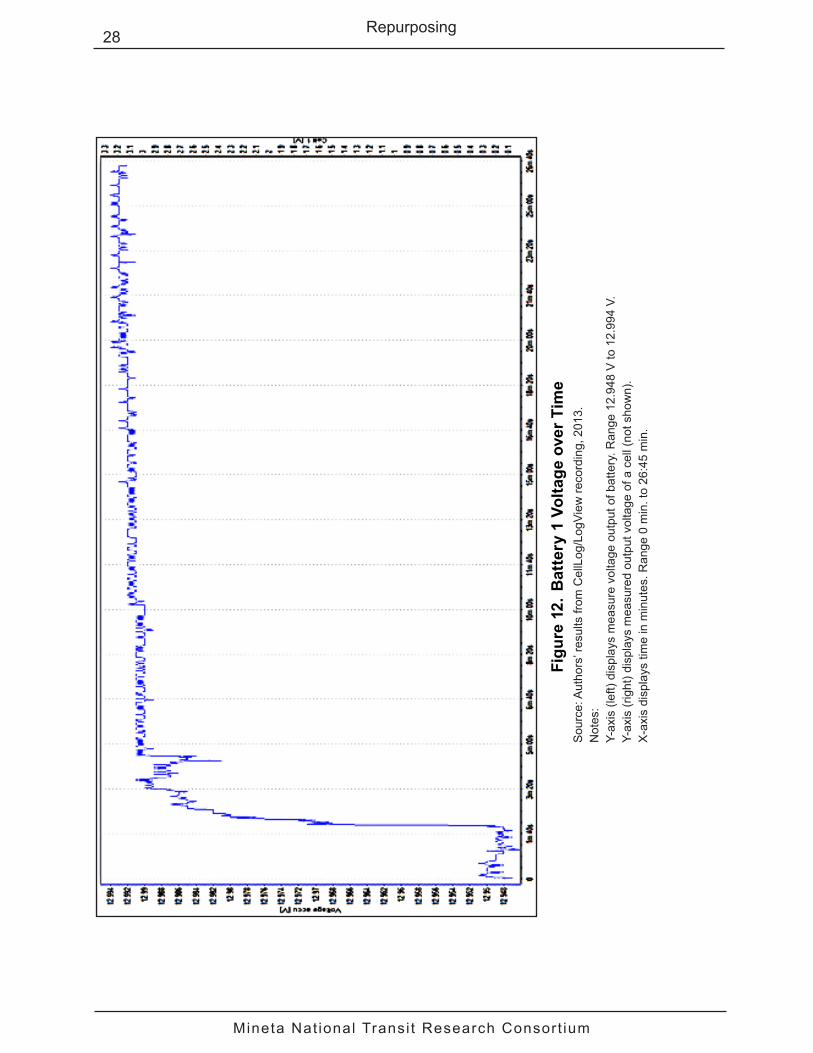
As shown in Figure 12, the voltage of the first battery was monitored at the same time as the voltages of the individual cells in battery 2 (shown in Figure 11). The largest increase in module voltage occurred within the first 3 minutes of the modules being connected. Steady state voltage was achieved after about 20 minutes, reaching 12.993 V, only slightly less than the target voltage of 13 V.
This demonstration showed the effectiveness of charging the ESS with the 2 solar panels. The test was conducted on April 21, 2013 at 3:00 p.m., near Rapid City, Michigan. To maximize solar gain, the solar panels were mounted at an angle of 70 degrees relative to the horizontal, facing the sun. Due to possible cloudy conditions, sunlight is a variable power source. As well, continuous fluctuations of the voltage levels observed were due in part to the BMS conducting cell balancing operations. The overall pack voltage for the solar test is shown in Figure 13. Horizontal trends in the data set are assumed to be caused by the times when the solar panels were not providing sufficient power to charge the pack (due to cloud cover).

Mineta Nat ional Transi t Research Consort ium
27Repurposing
Figu
re 1
1. B
alan
cing
of C
ells
in B
atte
ry 1
Sou
rce:
Aut
hors
’ res
ults
from
Cel
lLog
/Log
View
reco
rdin
g, 2
013.
Not
es:
Y-ax
is (l
eft)
disp
lays
mea
sure
d vo
ltage
out
put o
f bat
tery
. Ran
ge 1
2.94
8 V
to 1
2.99
4 V.
Y-ax
is (r
ight
) dis
play
s m
easu
red
volta
ge o
utpu
t of e
ach
cell.
Ran
ge 3
.224
V to
3.2
56 V
.X
-axi
s di
spla
ys ti
me
in m
inut
es. R
ange
0 m
in. t
o 19
:10
min
.R
ed is
bat
tery
cel
l 1; G
reen
is b
atte
ry c
ell 2
; Yel
low
is b
atte
ry c
ell 3
; Pin
k is
bat
tery
cel
l 4.
Mineta Nat ional Transi t Research Consort ium
28 Repurposing
Figu
re 1
2. B
atte
ry 1
Vol
tage
ove
r Tim
eS
ourc
e: A
utho
rs’ r
esul
ts fr
om C
ellL
og/L
ogVi
ew re
cord
ing,
201
3.N
otes
: Y-
axis
(lef
t) di
spla
ys m
easu
re v
olta
ge o
utpu
t of b
atte
ry. R
ange
12.
948
V to
12.
994
V.Y-
axis
(rig
ht) d
ispl
ays
mea
sure
d ou
tput
vol
tage
of a
cel
l (no
t sho
wn)
.X
-axi
s di
spla
ys ti
me
in m
inut
es. R
ange
0 m
in. t
o 26
:45
min
.

Mineta Nat ional Transi t Research Consort ium
29Repurposing
Figu
re 1
3. B
atte
ry P
ack
Ass
embl
y Vo
ltage
ove
r Tim
eS
ourc
e: A
utho
rs’ r
esul
ts fr
om C
ellL
og/L
ogVi
ew re
cord
ing,
201
3.N
otes
: Y-
axis
(lef
t) di
spla
ys m
easu
re v
olta
ge o
utpu
t of b
atte
ry. R
ange
12.
948
V to
12.
994
V.Y-
axis
(rig
ht) d
ispl
ays
mea
sure
d ou
tput
vol
tage
of a
cel
l (no
t sho
wn)
.X
-axi
s di
spla
ys ti
me
in m
inut
es. R
ange
0 m
in. t
o 31
:40
min
.

Mineta Nat ional Transi t Research Consort ium
30 Repurposing
MOBILE RECYCLING PLATFORM DESIGN
The design of a mobile recycling platform (MRP) demonstrates the reuse of post-vehicle-application lithium-ion batteries in an energy storage system. The MRP is a semi-mobile platform to create a deposit site for recyclable goods. The volume of goods is monitored to allow for as-needed retrieval, instead of using a predetermined time schedule. The platform must be powered through means other than attachment to the installed power-grid, as it may be placed at locations where grid connections are not available, such as at a county fair. The MRP consists of a collection of smaller assemblies divided into two main macro-assemblies: the storage assembly (SA) and the power assembly (PA).
The SA is the unit that is used by the public as the drop-off point for recycled goods. The SA is lit and monitored from within and without to ensure safety and checking the volume of goods deposited. The public should have enough access to allow depositing of the goods, but only authorized personnel should be able to remove the bins and access the interior. The SA must have enough space for a number of “bin-bays” and a workspace.
The superstructure consists of a modified, decommissioned semi-truck trailer as shown in Figure 14. The trailer is modified by removing sections of the side wall to allow the bins to be inserted from one side. The removed sections are then covered with doors, with holes cut into them through which the recycled goods can be inserted into the bins. The bin-bays are the spaces behind the side-doors of the superstructure where the bins are stored. Each bin-bay is separated externally by the door attached to the superstructure, but internally separated by vacant space. The workplace is a bin-bay devoid of bins, an area to store electrical control units, data storage/transmission units, and peripheral devices.
Figure 14. Mobile Recycling Platform (MRP) LayoutSource: Authors’ rendering.Notes: This MRP is a standard semi-truck trailer, approximately 53 feet long by 13.5 feet high by 8.5 feet wide.
A structure is suspended over the receiving side of the trailer. The overhang provides cover for persons using the MRP to deposit recyclable goods as well as providing mounting points for electronic equipment such as cameras and lights.

Mineta Nat ional Transi t Research Consort ium
31Repurposing
The receptacles for the goods are the bins within the trailer. The bins are on casters to allow mobility. The bins are constrained using their own weight. Bins are removed with a vehicle with a mechanized lift. The cameras are used to monitor the levels of goods within the bins. Night vision capability allows the cameras to see into the bins at night and during other low-light conditions. The wires from the cameras can then be fed either to a data retrieval device or to a power source, and the data transmitted wirelessly. LED lights are attached to the trailer and/or to an attached overhang. The lights provide adequate illumination for the cameras and for safety during bin removal. The data from the cameras are collected in a data-storage device (e.g., a DVR) periodically. The data are then sent to a separate location via a separate unit. Data transmission may be done via cell phone, through internet or other means determined by location of the MRP.
Power to run the MRP comes primarily from renewable energy, specifically solar. There must be enough power generated to completely power all equipment and charge the batteries comprising the energy storage system. The power generated from the solar panels is stored in repurposed lithium-ion batteries. The batteries are connected in parallel in order to maximize the amount of energy stored while keeping the voltage in line with the other PA components. A separate unit converts the power generated from the solar panels into a suitable format for the ESS. The power from the solar panels and battery banks are in DC, which the inverter transforms to AC. This is done to power the more common AC devices and to allow for the SA and the PA to be placed farther away with less voltage drop, as shown in Figure 15.
Figure 15. MRP Energy Storage System (ESS) SchematicSource: Authors’ schematic, 2013.
The power assembly contains several electrical components interconnected to perform the desired function. Table 4 summarizes power requirements. The power values are adjusted upward by 30% to compensate for loss from wiring, lengths of cord, and unknown hindrances to the electrical paths. There is one camera per bin-bay/receiving door, one LED

Mineta Nat ional Transi t Research Consort ium
32 Repurposing
floodlight for interior lighting, four LED tube lights illuminate the exterior of the receiving-side of the trailer, and one cell phone per camera, plus one backup phone.
Table 4. MRP Power Requirements
Item Description Quantity
Individual Wattage
(W)
Hours of Use per Day
(hr)
Total Watts (W)
Total Watt- Hours
(Wh)Camera Infra-red, to view bins and trailer 5 2.4 24 12 288Flood Light LED, to illuminate trailer inside 1 10 8 10 80Tube Light LED, to illuminate trailer outside 4 8 12 32 384DVR Records data received from
cameras1 35 24 35 840
Cell Phone Transmits data and/or creates LAN network for cameras
6 5.45 24 32.7 784.8
Total Assuming all units are on and using rated power conditions 121.7 2,376.8Adjusted Assuming 30% Factor of Safety 158.2 3,089.8
The number of batteries needed to meet the power requirements is calculated as follows. First, suppose that the prismatic battery packs used in the concept demonstration are employed. The power capacity in watt-hours (Wh) of a single battery is computed using Equation 2.
Power Capacity (Wh) = Voltage × Current (Eq. 2)
For a prismatic battery, this yields 720 Wh (i.e., 12 V × 60 amp-hours). Dividing the watt-hours per battery into the adjusted power requirements shown in Table 4 yields 4.46 batteries per day of energy storage required. For three days, 14 batteries would be required.
For cylindrical batteries, the same computations yield 21 batteries, as storage capacity is 480 watt-hours (i.e., 40 V × 12 amp-hours).
Mineta Nat ional Transi t Research Consort ium
33
VI. RECYCLING
Since the beginning of the development and mass manufacturing of lithium-ion batteries, increasing public concern about the environment has resulted in stricter regulations worldwide related to the adequate destination of hazardous residues containing heavy metals.35 The new lithium iron phosphate (LiFePO4) batteries contain no heavy metals, such as cobalt or nickel, and thus their recycling offers less opportunity for profit due to their inexpensive components and manufacturing. Nevertheless, recycling is still an important issue because of the potential flammability of the battery, toxic material within the battery, and massive space needed to dispose of voluminous numbers of units.
Since the lithium iron phosphate batteries are new to the market, no studies on their recycling currently exist. Studies on lithium cobalt oxide (LiCoO2) battery recycling were examined and acid leaching was identified as the most popular method. Based on these LiCoO2 recycling methods, laboratory-scale experiments were designed and conducted to determine which methods were most effective for recycling lithium iron phosphate batteries. Safety protocols and precautions were strictly followed, including manually disassembling the battery cells in a glove box with fume hood.
SAFETY AND PRECAUTIONS
Because metallic lithium in the used batteries can accumulate on the graphite anode by overcharging and abnormal deposition, and vigorous oxidation of metallic lithium with moisture or air can be dangerous, safety in mechanical treatment and waste minimization are most important for successful recovery of useful materials.36 Therefore, two problems need to be addressed for successful dismantling: disposal of harmful wastes and prevention of explosion.
Only five previous studies mention the hazard during opening the battery cells, and of those, four discuss needed precautions. The generally accepted methods for material recovery are hydrometallurgical and pyrometallurgical methods after mechanically dismantling the cells. Four studies mention required immersion of the cell into liquid nitrogen before cutting to prevent flames and explosions.37 Additionally, Georgi-Maschler et al. discuss how the Batres Company crushes batteries in a carbon dioxide (CO2) gas atmosphere.38 Thereby, the volatile organic electrolyte evaporates and is collected as non-usable condensate. However, for small lab-scale operations, a fume hood and vent are sufficient. Although not emphasized by all four studies, it is implied that the battery cell should be opened in a dry atmosphere, due to lithium’s violent reactivity with water vapor and possible short-circuiting when exposed to oxygen.
Lisbona and Snee performed a series of safety tests to identify hazards. The nail test is particularly worth noting, in which the cell was punctured by a nail driven into the surface at a constant speed (8 cm/s).39 There are two components to the heat generation as the cell is discharged: one from current flowing through the cell as the separator integrity is broken, and another from the current that flows through the nail. Heating of the cell is localized in and around the nail as opposed to the more uniform distribution that usually takes place in a conventional short-circuit test. Thermal runaway during a nail test is more

Mineta Nat ional Transi t Research Consort ium
34 Recycling
likely to occur when the cell is punctured by the nail at relatively shallow depths.40 As the contact area is relatively small in shallow depth punctures, heat dissipation will be limited. Heat generation during puncturing motivates preventing possible heat generation from inappropriate cutting of the battery cells during recycling.
BATTERY DISASSEMBLY
Methods of disassembly are specific to each battery type due to differences in packaging, structure, and components. Before a disassembly method was developed for the cylindrical lithium iron phosphate batteries, several previous studies were examined to determine the optimal way to successfully disassemble the cells in a controlled laboratory environment. Known industrial processes such as shredding and crushing were not emphasized.
According to Xu et al, the plastic cases of the batteries were removed using a small knife and a screwdriver.41 Then, the battery cell was immersed in liquid nitrogen for 4 minutes, so that the metallic shell that covers the battery could be cut easily and safely with a saw. The ends of the metallic shell were removed and a longitudinal cut was made, aiming to access the internal material of the battery, which was then removed using pliers. Finally, the anode and cathode were uncurled manually, separated and dried for 24 hours at 60°C. Contestabile et al. agree with Xu, and recommend refrigeration be used on an industrial scale.42
Lain discusses the extraction of the electrolyte by immersion in a suitable solvent for a few hours.43 After separation from the residual solids, the solvent can be recovered by evaporation at reduced pressure, leaving the pure electrolyte. The main requirements are that the boiling point at reduced pressure be below the lithium salt decomposition temperature (approximately 80°C), and that the material be available in an anhydrous state. However, no further information is given regarding a potential solution to extract the electrolyte, and the process is suspected to be not economical, due to the low quantity of electrolyte in each battery cell.
For this research, the equipment needed for the disassembly included a glove box with fume hood and air pump, a utility knife, and a sheet metal cutter. The disassembly procedure presented here was developed by trial and error through three successful iterations. There are a total of four layers within the jelly roll that comprises the cell beneath the outer cover. One layer is an aluminum foil coated with LiFePO4 (the cathode with the glossy black coating shown in Figure 16), one layer is copper foil coated with graphite (the anode with the matte black coating shown in Figure 16), and the other two beige layers (shown in Figure 16) are separator membranes with electrolyte residue on them. At the center of the jelly roll is a metallic tube made of stainless steel. The black fragments scattered in this image are copper and graphite chips from the corroded copper foil. As expected, the LiFePO4-coated aluminum layer appeared to be mechanically and chemically intact, but like the copper foil, it was extremely easy to tear the aluminum foil without proper handling. Finally, the coatings on both the copper and aluminum foils were unable to be scratched off cleanly, thus either a hydrothermal or chemical method is required for material extraction.

Mineta Nat ional Transi t Research Consort ium
35Recycling
Figure 16. Layout of a Disassembled LiFePO4 Cell with an Unopened CellSource: Authors’ photo, 2013.
MATERIAL EXTRACTION
As seen from the dismantling process, the LiFePO4 cell consists of a graphite-coated copper foil (anode), LiFePO4-coated aluminum foil (cathode), two separator layers, liquid electrolyte, plastic components, and aluminum shells. The coatings must be separated from the copper and aluminum foil.
Most current studies focus on lithium cobalt oxide batteries.44 Since lithium iron phosphate batteries are new to the market, no previous research studies about them were found. An acid leaching method was used in most existing studies to separate coatings and foils. This method uses acid to dissolve solid electrode material, after which a solvent extraction, precipitation method, etc., are used to separate the metal.45
Although the processes mentioned above were at a pilot or laboratory testing phase, the concern of environmental influences for large industrial applications could not be ignored. Thus, most existing research promotes non-toxic extracting reagents for the chemical process.
Before acid leaching, extraction methods used N-Methyl-2-pyrrolidone (NMP) to filter out the copper and aluminum foils at elevated temperatures (60°C and 100°C) for 1 hour.46
Mineta Nat ional Transi t Research Consort ium
36 Recycling
For the acid leaching process, HCl, H2SO4, or HNO3 are generally used. According to Lee and Rhee,47 using H2SO4, or HNO3 as the leaching agent, with the addition of hydrogen peroxide (H2O2) as a reducing agent, could increase the leaching efficiency of cobalt by 45% and lithium by 10% compared with that in only nitric acid leaching, but the effect on LiFePO4 remains uncertain. The leaching reaction is as follows:
2LiCoO2 + 6H+ +H2O2 ↔ 2Co2+ + O2 +2Li+ + 4H2O (Eq. 3)
Cyanex 272 was the most popular choice among the existing research in solvents extraction, and was used to extract aluminum and cobalt at different pH values. According to Kosaraju, the use of Cyanex in Solvent 70 results in the extraction of 90% lithium at pH values from 0.1 to 1.0.48
One phenomenon observed during the material separation process was that, after several weeks of storage inside the fume hood, the copper foil and graphite coating separated without any effort when a cell was dismantled, as compared to another cell stored outside of the fume hood with the graphite coating securely attached to the copper foil. Potential cause for this phenomenon is the constant exposure to acidic gas over a certain period of time. Acidic gas produced inside the fume hood consists of the vapor phase of H2SO4, HNO3, sulfur dioxide (SO2), and nitrogen dioxide (NO2). However, since the H2SO4 and HNO3 vapor occupies minimal volume, over only a short period of time inside the fume hood during material separation process, the probability for SO2 or NO2 as the contributor to this phenomenon is higher.
To verify the type of gas that triggered the material separation and duplicate the results, an experiment was performed. The gas tests were conducted using two sealed bottles and designated LiFePO4 cells. In order to collect SO2 and NO2 in adequate concentration, 2 mol/L H2SO4 and HNO3 were used to react with cathode and anode material, respectively. In order to collect as much gas as possible, a beaker with a small diameter was used to contain the reaction. A glass funnel was positioned inverted to cover the beaker’s top, so that the gas would rise through the funnel tube into the bottle stationed above. Due to the non-sealed gas collection setup, not all the gas produced from the reactions could be collected. However, the concentration level of the gas in the bottle could be estimated through color observation.
The binder used on the coating for both electrodes is polyvinylidene fluoride (PVdF), which is approximately 5% of the weight of the electrode. By weight, the anode consists of 30% copper, and 60% graphite; the cathode consists of 15% aluminum, and 75% LiFePO4. In a series of control tests, the graphite-coated copper foil and LiFePO4-coated aluminum foil were immersed in aqueous H2SO4 and HNO3 solutions, respectively. The temperatures tested were room temperature (25°C), 60°C, 80˚C and 100°C, as suggested by Xu et al. and Li et al.49 To test the effect of NMP on separating the anode and cathode material, the copper foil and aluminum foil were separately immersed in pure NMP and aqueous NMP solution at elevated temperature.
The theoretical reaction between copper and H2SO4 is shown in Equation 4:

Mineta Nat ional Transi t Research Consort ium
37Recycling
Cu(s) + 2H2SO4 (aq) 2H2O(l) + SO2(g) + CuSO4(aq) (Eq. 4)
where the resulting solution (CuSO4) is blue, and a yellow gas (SO2) can be observed.
The reaction between aluminum and HNO3 is shown in Equation 5:
2Al(s) + 6HNO3(aq) 2Al(NO3)3(aq) + 3H2(g) (Eq. 5)
However, the aluminum foil and LiFePO4 coating were put into the HNO3 at the same time so that the nitric acid would oxidize the Fe2+ to Fe3+ as shown in Equation 6:
H+ + HNO3(aq) + Fe2+ NO2(g) + H2O + Fe3+ (Eq. 6)
The released NO2 gas for this reaction is dark yellow and toxic; hence the necessity of a fume hood. The concentration of both H2SO4 and HNO3 started at 2 mol/L, as suggested by Xu et al.50 The reduced concentrations of 1 mol/L and 0.5 mol/L were used to investigate whether the same leaching effects would occur under more economical conditions.
The test specifications are given in Table 5. The purpose of the tests was to separate the material, not to convert the metal foil to aqueous solution. So the leaching agents were expected not to deplete after the separation of the material, hence the low pH value after leaching tests was predicted. The effect of LiFePO4 in the reaction between aluminum and nitric acid (HNO3) is currently ignored until a better understanding of its behavior can be gained, so that the lithium within the LiFePO4 can be extracted in the future.
Table 5. Material Separation and Extraction Tests with Aluminum and Copper Foil Using H2SO4, HNO3, and NMP
Test No. Solid Agent
Acid Concentration (mol/L)
Temperature (°C)
Time (min.)
1a Al HNO3 2.00 40.00 11b Al HNO3 0.50 40.00 11c Al HNO3 0.50 50.00 12a Cu H2SO4 2.00 33.00 12b Cu H2SO4 1.00 40.00 12c Cu H2SO4 0.50 40.00 13a Al NMP 2.00 60.00 603b Cu NMP 2.00 60.00 60
Table 6 shows the specifications for three additional acid leaching tests. In previous tests, the mass of copper and aluminum were calculated with complete reaction in mind, which means the acid present inside the beaker is able to react with all the foil inserted. However, the purpose of the tests was merely to separate the foil from the coating, rather than completely dissolving the foil in the acid. Thus, all previous tests had leftover acid with metal foil removed after the material extraction. The three acid leaching tests presented

Mineta Nat ional Transi t Research Consort ium
38 Recycling
in the following table propose more metal foil than the acid could fully dissolve in the short period of time allowed to separate the coating from the metal foil.
Table 6. Material Preparation and Extraction Tests with Excessive Aluminum and Copper Foil
Test No. Solid Agent
Acid Concentration (mol/L)
Temperature (°C)
Time (min.)
4a Cu H2SO4 0.50 30.00 24b Al HNO3 0.50 50.00 24c Al HNO3 0.50 50.00 2
Table 7 shows the reactions during the gas collection process. The last column represents the time the cell was stored inside the bottle before opening.
Table 7. Reactions for Gas Collection TestsTest No. Solid Agent
Acid Concentration (mol/L)
Temperature (°C)
Time (days)
5a Al HNO3 2.00 50.00 3.005b Al HNO3 2.00 50.00 4.005c Cu H2SO4 2.00 33.00 3.00
RESULTS AND DISCUSSION
For test 1a (Table 5), bubbles formed on the surface of the foil immediately after the foil was immersed in the HNO3 solution. Total separation of LiFePO4 and aluminum occurred after 0.5 minutes, along with the solution turning yellow and minor heat dissipation (2°C temperature rise). A yellow-colored gas was released, suggesting simultaneous reaction between HNO3 and LiFePO4, with the release of NO2. After separation and drying of the material, the LiFePO4 layer became brittle, while the aluminum foil appeared intact. The concentration of HNO3 was decreased to 0.5 mol/L in test 1b (Table 5) and similar results occurred. By observation, about 90% of the LiFePO4 coating detached from the aluminum foil after 1 minute, and no emission of yellow gas was observed. To improve the material separation with low concentration of the HNO3, the temperature was increased to 50°C in test 1c (Table 5). By observation, more than 95% of the LiFePO4 coating detached from the aluminum foil after 1 minute, but a light emission of yellow gas was observed. After the drying of the material, serried ranks of small holes were observed on the LiFePO4 surface. Due to extreme chemical inertness and high thermal stability of PVdF binder, it is possible that the HNO3 at the elevated temperature had damaged the structure of LiFePO4, and further examination of the remaining solution will be needed.51 Future testing includes prolonging the test period to 2 minutes to ensure total separation of the foil and coating with light concentration of the leaching agent.

Mineta Nat ional Transi t Research Consort ium
39Recycling
For test 2a (Table 5), bubbles formed on the surface of the copper foil immediately after the foil was immersed in the H2SO4 solution. Separation of graphite and copper occurred after 0.5 minutes along with the solution turning blue and minor heat dissipation (4°C temperature rise). A yellow-colored gas was released, suggesting the release of SO2. Since graphite does not react with H2SO4, the separation of the material is simple. Serried ranks of small holes were observed on the copper foil, suggesting corrosion of the copper occurred during the fast reaction with the sulfuric acid. The concentration of the sulfuric acid dropped to 1 mol/L for test 2b, and to 0.5 mol/L for test 2c, while the temperature was kept constant. For these tests, the resulting solution had a light green color, and no corrosion was observed on the copper foil, and the other observed results remained the same. Future studies include further decreasing the H2SO4 concentration for more economical results.
Two tests (3a and 3b, shown in Table 5) using NMP were conducted with anode and cathode foils, but the results were not successful. The temperature was kept at 60°C, and the concentration of the NMP was 2 mol/L. For the cathode foil, bubbles were observed on the surface immediately. After 60 minutes, the remaining solution had a light yellow color with orange precipitate. The separation of the aluminum and LiFePO4 was minimal, and both became brittle and were corroded after drying. The remaining solution had a pH value of 4.0, while the NMP had a pH of 7.0. For the anode foil, bubbles were observed on the surface immediately. After 60 minutes, the remaining solution had a dark yellow color, and a pH value of 6.0. The separation of copper and graphite was minimal, but no corrosion of the copper was observed. Because of the high cost of NMP and the high concentration needed to achieve similar results to those by much cheaper acid at lower concentration, the NMP extraction method is not a feasible option for the large-scale recycling application.
The results from the tests described in Table 6 verified the prediction: 40mL leaching agent H2SO4 at 0.5 mol/L was capable of separating 5 g of copper from the graphite coating in 2 minutes. Gas and heat dissipation were minimal, and the solution after 2 minutes was light green. Using 40 mL of leaching agent HNO3 at 0.5 mol/L was capable of separating 3 g of aluminum from the LiFePO4 coating in 2 minutes, and the gas and heat dissipation were also minimal. However, the shape of the foil played a negative role in this set of experiments. Due to the shape limitation of the beaker, the electrode foil had to be folded in order to submerge totally into the leaching agent, thus reducing the available surface of reaction. In the future, to achieve the highest reaction efficiency, shredding the electrode foil prior to reaction is recommended.
Using NO2 gas to separate copper foil from the graphite coating prior to dismantling the cell was successful (see summary in Table 7), while using SO2 gas was not. On the second day, the yellow color faded inside the NO2 bottle, suggesting the gas was being absorbed into the cell. Meanwhile, signs of corrosion were observed on the end of the cell inside the NO2 bottle. After three days, both cells from the NO2 bottle and SO2 bottle were taken out. The cell in the NO2 bottle had one side of the graphite coating come off the copper foil, while the cell in SO2 bottle still had the coating intact. The outer shell of the cell in the NO2 bottle showed signs of corrosion, while the one in SO2 had none. These results demonstrate that SO2 was not the trigger for self-separation of the graphite coating, and

Mineta Nat ional Transi t Research Consort ium
40 Recycling
longer time inside the NO2 bottle would be needed for the graphite coating to separate completely from copper foil.
The second phase of the test focused on the use of NO2 only. After 4 days, the cell was taken out of the bottle, and the graphite coating came off completely. One thing worth noting is the observed longitudinal tear on the aluminum shell of the cell, caused by the expansion of the jelly roll. The cathode material appeared to be intact, suggesting the HNO3 vapor did not have significant effect during the test. Otherwise, the HNO3 vapor would react with the cathode. The result suggests that technically, copper-graphite separation with acidic gas is a viable option. However, unless direct supply of NO2 gas is present in large-scale applications, using a chemical reaction to produce NO2 for material extraction would cost more than using 0.5 mol/L H2SO4. Future work includes optimal concentration measurement of NO2 to achieve copper-graphite self-separation, component determination of the results from lithium extraction, and refinement of the lithium extraction method.

Mineta Nat ional Transi t Research Consort ium
41
VII. SUMMARY AND CONCLUSION
Increased fuel economy standards, as well as more stringent greenhouse gas emission standards, are driving vehicle manufacturers toward electrification. The efficient energy storage provided by lithium-ion batteries implies that their use in vehicles will continue to expand with electrification. Increased use in vehicles makes the issue of what to do with post-vehicle-application lithium-ion batteries even more important.
Lithium-ion batteries provide compact, dense energy storage, which along with their chemical composition, implies that they must be handled with proper safety procedures. The principles of environmentalism and sustainability imply that the processing of post-vehicle-application batteries must be done in a way that is not harmful to Earth and that does not unnecessarily consume natural resources. Thus, recycling of the materials comprising the batteries must be considered, even if not currently economically viable.
A forecasting model for the number of post-vehicle-application lithium-ion batteries was used to ensure sufficient supply to support such processing. The model considered multiple, wide ranging vehicle demand forecasts, a probability distribution of vehicle application life, and a percent useable factor for post-vehicle-application batteries. Results show that by 2035, the number of available post-vehicle-application batteries ranges from 1.376 million in the pessimistic forecast to 6.759 million in the optimistic forecast, with a middle forecast of 3.773 million, enough batteries to justify remanufacturing, repurposing, and recycling efforts. More importantly, the number of available post-vehicle-application batteries is between approximately 55% and 60% of the number of batteries needed for new EV and PHEV production, further supporting the opportunity for remanufacturing. In 2050, this range is projected to be approximately 70% to 85%, showing a growing opportunity for remanufacturing. These results support the development of repurposing and recycling processes as well.
A cost-benefit analysis was done independently for each of the three types of post-vehicle-application processing: remanufacturing, repurposing, and recycling. Costs included those for operations, transportation, material handling, infrastructure development, and facility development. Benefits included avoided costs for storage of batteries and production of new batteries, as well as sales of repurposed batteries and recovered materials in recycled batteries. Remanufacturing was shown to be cost effective, primarily due to the avoided costs of producing new batteries when a remanufactured battery could be used instead. Repurposing is a less defined application area. However, repurposing was shown to be economically feasible when the development costs of repurposing applications were less than $83/kWh to $114/kWh, depending on research and development expenses.
Recycling in isolation is not economically feasible, as lithium-ion batteries are composed of relatively inexpensive materials. However, recycling can support closed-loop supply chains reusing materials from post-vehicle-application batteries in the production of new batteries as well as supporting the principles of environmentalism and sustainability. Recycling can occur following a vehicle application as well as following a repurposing application.
Mineta Nat ional Transi t Research Consort ium
42 Summary and Conclusion
Remanufacturing involves transforming a post-vehicle-application battery to once again meet the standards for use in a moving vehicle. Proprietary processes for remanufacturing have been developed by Sybesma’s Electronics. These include battery testing. Even with proper safe testing management, a fail-safe environment must be provided, which is accomplished through a specially designed and constructed workbench. The workbench is fire resistant and allows the operator to drop a battery into a safe container in case of a negative event. The container may be safely transported outdoors.
Repurposing will most often be focused on stationary energy storage applications. Development of a battery management system appropriate to each particular energy storage system is the biggest technical challenge, along with reconfiguring the cells comprising the battery.
A concept demonstration of one such application was developed. Energy is obtained from the energy storage system through a standard electric plug. There are a variety of options for energy input to the storage system, including a standard charger and solar panels. A computer system with appropriate software is included to monitor the charging and discharging of the system. Tests were conducted to show that charging and discharging could be done effectively. The energy storage system consists of two batteries known to have similar state-of-life characteristics. The original equipment manufacturer provided a battery management system consisting of a MOSFET transistor board and a main control board for charge control.
A second, more realistic scale repurposing application, an energy storage system for a semi-mobile recycling platform to create a mobile site for recycled goods, has been designed and is currently under development. The platform must be powered through means other than attachment to the installed power-grid. The volume of delivered recyclable goods is monitored to allow for as-needed retrieval, instead of on a predetermined schedule. The energy storage system must support cameras, flood lights for site illumination, tube lights for internal platform illumination, a DVR, and one or more cell phones for transmission of monitoring information. Energy input to the storage system will be collected by solar panels. A storage system control panel will be developed.
Recycling efforts focused on cleanly separating and thus recovering copper, aluminum, iron phosphate, and lithium from batteries. Since the lithium iron phosphate batteries are new to the market, no studies on their recycling currently exist. Thus, laboratory-scale experiments were designed and conducted based on a review of previous studies concerning lithium cobalt oxide batteries. Acid leaching was identified as the most popular method for extracting raw materials from lithium cobalt oxide batteries. Methods of disassembly are specific to each battery type due to differences in packaging, structure, and components. In this case, disassembly equipment includes a glove box with fume hood and air pump, a utility knife, and a sheet metal cutter. There are a total of 4 layers within the jelly roll that comprise the cell beneath the outer cover: aluminum foil coated with LiFePO4, copper foil coated with graphite, and the other 2 separator membranes with electrolyte residue on them. At the center of the jelly roll is a metallic tube made of stainless steel. Material extraction means separating the coatings from the copper and aluminum foils. Acid leaching using nitric acid for aluminum and sulfuric acid for copper

Mineta Nat ional Transi t Research Consort ium
43Summary and Conclusion
was successful at separating the coatings from the foils. The experiments were conducted at various temperatures ranging from 33°C to 60°C. The material was exposed to the acid for either 1 or 2 minutes. Other, unsuccessful, experiments were conducted using NMP.
Additional work is needed in repurposing and recycling. The former involves constructing a realistic demonstration such as the portable recycling facility. We are exploring the possibility of replacing the gasoline engine in a golf cart with repurposed batteries. Additional validation of the recycling process will be attempted through its application to batteries from other manufacturers such as LGChem and Johnson Controls.

Mineta Nat ional Transi t Research Consort ium
44 Summary and Conclusion

Mineta Nat ional Transi t Research Consort ium
45
ABBREVIATIONS AND ACRONYMS
AC Alternating CurrentBMS Battery Management SystemCAFE Corporate Average Fuel Economy Co CobaltCO2 Carbon DioxideCO2e Carbon Dioxide EquivalentDC Direct CurrentDVR Digital Video RecorderEIA Energy Information AdministrationEOL End of (Vehicle) LifeESS Energy Storage SystemEV Electric VehicleGVSU Grand Valley State UniversityHCl Hydrochloric AcidH2SO4 Sulfuric AcidHNO3 Nitric AcidH2O WaterH2O2 Hydrogen PeroxideIEA International Energy AgencyKg KilogramkWh Kilowatt-HourLEAP Long-Range Energy Alternatives Planning SystemLED Light Emitting DiodeLi LithiumLiCoO2 Lithium Cobalt OxideLiFePO4 Lithium Iron PhosphateMCB Main Control Boardmol/L Moles Per LiterMOSFET Metal-Oxide-Semiconductor Field-Effect Transistormpg Miles per GallonMRP Mobile Recycling PlatformmV Milli-VoltNMP N-Methyl-2-Pyrrolidone NO2 Nitrogen DioxideO OxygenPA Power AssemblyPHEV Plug-In Hybrid Electric VehiclePVdF Polyvinylidene Fluoride

Mineta Nat ional Transi t Research Consort ium
46 Abbreviations and Acronyms
R&D Research and DevelopmentSA Storage AssemblySO2 Sulfur DioxideV Volt

Mineta Nat ional Transi t Research Consort ium
47
ENDNOTES
1. Center for Climate and Energy Solutions, FederalVehicleStandards (2013), http://www.c2es.org/federal/executive/vehicle-standards (accessed October 1, 2013).
2. GM-Volt.com, “Chevy Volt Specs” (2011), http://gm-volt.com/full-specifications (accessed August 31, 2013).
3. J. Neubauer and A. Persaran, “The Ability of Battery Second Use Strategies to Impact Plug-In Electric Vehicle Prices and Serve Utility Energy Storage Applications,” JournalofPowerSources 196, no. 23 (2011): 10351.
4. E. L. Schneider, W. Kindlein, S. Souza, and C. F. Malfatti, “Assessment and Reuse of Secondary Batteries Cells,” JournalofPowerSources 189, no. 2 (2009): 1264.
5. A. Andrijanovits, H. Hoimoja, and D. Vinnikov, “Comparative Review of Long-term Energy Storage Technologies for Renewable Energy Systems,” Electronics andElectricalEngineering 2, issue 118 (2012): 21; Z. Yang, J. Liu, S. Baskaran, C. H. Imhoff, and J. D. Holladay, “Enabling Renewable Energy and the Future Grid with Advanced Electricity Storage,” JOM 62, no. 9 (2012): 14-23; F. Diaz-Gonzalez, “A Review of Energy Storage Technologies for Wind Power.” Renewable&SustainableEnergyReviews 16, no. 4 (2012): 2154.
6. J.F. Paulino, N. G. Busnardo, and J. C. Afonso, “Recovery of Valuable Elements from Spent Li-Batteries,” JournalofHazardousMaterials 150, no. 3 (2008): 843.
7. BCG-The Boston Consulting Group, “Batteries for Electric Cars: Challenges, Opportunities, and the Outlook to 2020,” BCG Focus (2010), http://www.bcg.com/expertise_impact/industries/energy_environment/publicationdetails.aspx?id=tcm:12-36622&mid=tcm:12-36569 (accessed August 31, 2013).
8. U.S. Energy Information Administration (EIA), “Future Vehicle Demand 2010 Data Tables” (Washington, D.C., 2010).
9. International Energy Agency (IEA), “Technology Roadmap: Electric and Plug-In Hybrid Electric Vehicles” (June 2011), http://www.iea.org/publications/freepublications/publication/name,3851,en.html (accessed August 31, 2013).
10. Commend, An Introduction to Leap (2012), http://www.energycommunity.org (accessed August 31, 2013).
11. B.J. Jody, E. J. Daniels, C. M. Duranceau, J. A. Pomykala Jr., and J. S. Spangenberger, “End-of-Life Vehicle Recycling: State of the Art of Resource Recovery from Shredder Residue” (September 2010), Center for Transporation Research, Argonne National Laboratory Publication, http://www.es.anl.gov/Energy_systems/CRADA_Team/publications/End%20of%20life%20vehicle%20recycling%20Technology%20review.pdf (accessed August 31, 2013).

Mineta Nat ional Transi t Research Consort ium
48 Endnotes
12. GM-Volt.com, “Chevy Volt Specs.”
13. Sam Abuelsamid, “General Motors builds first Volt battery pack on production line” (2010), http://green.autoblog.com/2010/01/07/general-motors-builds-first-volt-battery-pack-on-production-line/ (accessed February 12, 2014).
14. L. Gaines and R. Cuenca, Costs of Lithium-ion Batteries for Vehicles, Center for Transportation Research, Argonne National Laboratory Publication (May 2000), http://www.transportation.anl.gov/pdfs/TA/149.pdf (accessed August 31, 2013).
15. Ibid.
16. GM-Volt.com, “Chevy Volt Specs.”
17. Ibid.
18. Dan Curtis, “The Value of Climate Control: What It Means Inside Self Storage” (September 2003), http://www.insideselfstorage.com/articles/2003/09/the-value-of-climate-control.aspx (accessed August 31, 2013).
19. H. Haruna, S. Itoh, T. Horiba, E. Seki, and K. Kohno, “Large-Format Lithium-Ion Batteries for Electric Power Storage,” JournalofPowerSources 196, no. 16 (2011): 7002.
20. Shandra Martinez, “LG Chem to Build $303 Million Lithium Battery Plant in Holland for Chevrolet Volts” (2010), http://www.mlive.com/business/west-michigan/index.ssf/2010/03/lg_chem_to_build_1st_north_ame.html (accessed August 31, 2013).
21. Gaines and Cuenca, CostsofLithium-IonBatteriesforVehicles.
22. Jody et al., “End-of-Life Vehicle Recycling.”
23. T. Georgi-Maschler, B. Friedrich, R. Weyhe, H. Heegn, and M. Rutz, “Development of a Recycling Process for Li-Ion Batteries,” JournalofPowerSources 207 (2012): 173.
24. J. Xu, H. R. Thomas, R. W. Francis, K. R. Lum, J. Wang and B. Liang, “A Review of Processes and Technologies for the Recycling of Lithium-Ion Secondary Batteries.” JournalofPowerSources 177, no. 2 (2008): 512.
25. A. Kumar, “Second Life and Recycling of EV Batteries Will Ensure the Completion of ‘Green Car’ Tag” (2010) AutomotiveandTransportation, http://www.frost.com/sublib/display-market-insight-top.do?id=216476073 (accessed August 31, 2013).
26. J. Dewulf, G. Van der Vorst, K. Denturck, H. Van Langenhove, W. Ghyoot, J. Tytgat, and K. Vandeputte, “Recycling Rechargeable Lithium Ion Batteries: Critical Analysis of Natural Resource Savings,” Resources,ConservationandRecycling 54, no. 4 (2010): 229.

Mineta Nat ional Transi t Research Consort ium
49Endnotes
27. Gaines and Cuenca, CostsofLithium-IonBatteriesforVehicles.
28. O. Egbue and S. Long, “Barriers to Widespread Adoption of Electric Vehicles: An Analysis of Consumer Attitudes and Perceptions,” EnergyPolicy, no. 48 (2012): 717-729.
29. P.W. Gruber, P. A. Medina, G. A. Keoleian, S. E. Kesler, M. P. Everson, and T. J. Wallington, “Global Lithium Availability.” JournalofIndustrialEcology 15, no. 5 (2011) [doi: 10.1111/j.1530-9290.2011.00359.x]: 760-775.
30. L. Gaines and P. Nelson, Lithium-Ion Batteries: PossibleMaterials Issues, Center for Transportation Research, Argonne National Laboratory Publication (2010), http://www.transportation.anl.gov/pdfs/B/583.PDF (accessed August 31, 2013).
31. L. Gaines and P. Nelson, Lithium-Ion Batteries: Examining Material Demand andRecyclingIssues, report by: Argonne National Laboratory, Argonne, IL. 2011. http://www.transportation.anl.gov/pdfs/B/626.PDF (accessed August 31, 2013).
32. Siemens, “SM46; Siemens Solar Module Details and Specifications” (no date), http://www.siemen.co.uk/sm46.html (accessed May 31, 2014).
33. Hobby King (supplier), “Cell-Log 8M Cell Voltage Monitor 2-8S Lipo” (no date), http://www.hobbyking.com/hobbyking/store/__10952__Cell_Log_8M_Cell_Voltage_Monitor_2_8S_Lipo.html (accessed May 30, 2014).
34. Geokon, Model8001-3Software;LogViewSoftware” (January 2014), www.geokon.com/content/datasheets/8001-3_LogView_Software.pdf (accessed May 30, 2014).
35. Xu, et al., “A Review of Processes and Technology.”
36. Ibid.
37. Xu, et al., “A Review of Processes and Technology”; M. Contestabile, S. Panero, and B. Scrosati, “A Laboratory-Scale Lithium-Ion Battery Recycling Process,” JournalofPowerSources, 92 (2001): 65-69; Georgi-Maschler et al., “Development of a Recycling Process for Li-Ion Batteries”; Michael J. Lain, “Recycling of Lithium Ion Cells and Batteries,” JournalofPowerSources 97-98 (2001): 736-738.
38. Georgi-Maschler et al., “Development of a Recycling Process for Li-Ion Batteries.”
39. D. Lisbona, and T. Snee, “A Review of Hazards Associated with Primary Lithium and Lithium-Ion Batteries,” ProcessSafetyandEnvironmentalProtection89 (2011): 434-442.
40. R. Spotnitz and J. Franklin, “Abuse Behavior of High-Power, Lithium-Ion Cells,” JournalofPowerSources113 (2003): 81–100; M.S. Wu, P. C. J. Chiang, J. C. Lin, and Y. S. Jan “Correlation between Electrochemical Characteristics and Thermal Stability of

Mineta Nat ional Transi t Research Consort ium
50 Endnotes
Advanced Lithium Ion Batteries in Abuse Tests- Short-Circuit Tests,” ElectrochimicaActa 49 (2004): 1803–1812.
41. Xu, et al., “A Review of Processes and Technology.”
42. Contestabile et al., “A Laboratory-Scale Lithium-Ion Battery Recycling Process.”
43. Lain, “Recycling of Lithium-Ion Cells and Batteries.”
44. R. Wang, Y. Lin, and S. Wu “A Novel Recovery Process of Metal Values from the Cathode Active Materials of the Lithium-Ion Secondary Batteries,” Hydrometallurgy 99 (2009): 194-201; L. Li, J. Ge, R. Chen, F. Wu, S. Chen and X. Zhang, “Environmental Friendly Leaching Reagent for Cobalt and Lithium Recovery from Spent Lithium Ion Batteries,” WasteManagement 30 (2010): 2615-2621.
45. Wang et al., “A Novel Recovery Process.”
46. Li et al., “Environmentally Friendly Leaching”; Contestabile et al., “A Laboratory-Scale Lithium-Ion Battery Recycling Process.”
47. C.K. Lee and K. I. Rhee, “Preparation of LiCoO2 from spent lithium-ion batteries,” JournalofPowerSources 109 (2002): 17–21.
48. S. Kosaraju, “Investigation of Hev Li-ion Batteries for Lithium Recovery,” Master’s thesis, Chalmers University of Technology, Göteborg, Sweden, 2012.
49. Xu et al., “A Review of Processes”; Li et al., “Environmentally Friendly Leaching.”
50. Xu et al., “A Review of Processes.”
51. J. Zhao, K. K. C. Ho, S. Shamsuddin, A. Bismarck, and V. Dutschk, “A Comparative Study of Fibre/Matrix Interface in Glass Fibre Reinforced Polyvinylidene Fluoride Composites,” Colloids and SurfacesA: Physicochemical and EngineeringAspects 413 (2012): 58-64.

Mineta Nat ional Transi t Research Consort ium
51
BIBLIOGRAPHY
Abuelsamid, Sam. “General Motors Builds First Volt Battery Pack on Production Line.” 2010. http://green.autoblog.com/2010/01/07/general-motors-builds-first-volt-battery-pack-on-production-line/ (accessed February 12, 2014).
Andrijanovits, A., H. Hoimoja, and D. Vinnikov. “Comparative Review of Long-term Energy Storage Technologies for Renewable Energy Systems.” ElectronicsandElectricalEngineering 2, issue 118 (2012): 21.
BCG-The Boston Consulting Group. “Batteries for Electric Cars: Challenges, Opportunities, and the Outlook to 2020.” BCGFocus. 2010. http://www.bcg.com/expertise_impact/industries/energy_environment/publicationdetails.aspx?id=tcm:12-36622&mid=tcm:12-36569 (accessed August 31, 2013).
Center for Climate and Energy Solutions. FederalVehicleStandards. 2013. http://www.c2es.org/federal/executive/vehicle-standards (accessed October 1, 2013).
Commend. AnIntroductiontoLeap. 2012. http://www.energycommunity.org (accessed August 31, 2013).
Contestabile, M., S. Panero, and B. Scrosati. “A Laboratory-Scale Lithium-ion Battery Recycling Process.” JournalofPowerSources 92 (2001): 65-69.
Curtis, Dan. “The Value of Climate Control: What It Means Inside Self Storage.” September 2003. http://www.insideselfstorage.com/articles/2003/09/the-value-of-climate-control.aspx (accessed August 31, 2013).
Dewulf, J., G. Van der Vorst, K. Denturck, H. Van Langenhove, W. Ghyoot, J. Tytgat, and K. Vandeputte. “Recycling Rechargeable Lithium Ion Batteries: Critical Analysis of Natural Resource Savings.” Resources,ConservationandRecycling 54, no. 4 (2010): 229.
Diaz-Gonzalez, F. “A Review of Energy Storage Technologies for Wind Power.” Renewable&SustainableEnergyReviews 16, no. 4 (2012): 2154.
Egbue, O, & Long, S. Barriers to Widespread Adoption of Electric Vehicles: An Analysis of Consumer Attitudes and Perceptions. EnergyPolicy, no. 48 (2012): 717-729.
Gaines, L. and R. Cuenca. CostsofLithium-ionBatteriesforVehicles. Center for Transportation Research, Argonne National Laboratory Publication. May 2000. http://www.transportation.anl.gov/pdfs/TA/149.pdf (accessed August 31, 2013).
Gaines, L. and P. Nelson. Lithium-ionBatteries:PossibleMaterialsIssues. Center for Transportation Research, Argonne National Laboratory Publication. 2010. http://www.transportation.anl.gov/pdfs/B/583.PDF (accessed August 31, 2013).

Mineta Nat ional Transi t Research Consort ium
52 Bibliography
Gaines, L., and P. Nelson. Lithium-ionBatteries:ExaminingMaterialDemandandRecyclingIssues. Report by: Argonne National Laboratory, Argonne, IL. 2011. http://www.transportation.anl.gov/pdfs/B/626.PDF (accessed August 31, 2013).
Geokon. Model8001-3Software;LogViewSoftware.” January 2014. http://www.geokon.com/content/datasheets/8001-3_LogView_Software.pdf(accessed May 30, 2014).
Georgi-Maschler, T., B. Friedrich, R. Weyhe, H. Heegn, and M. Rutz. “Development of a Recycling Process for Li-Ion Batteries.” JournalofPowerSources 207 (2012): 173.
GM-Volt.com. “Chevy Volt Specs.” 2011. http://gm-volt.com/full-specifications (accessed August 31, 2013).
Gruber, P.W., P. A. Medina, G. A. Keoleian, S. E. Kesler, M. P. Everson, and T. J. Wallington. “Global Lithium Availability.” JournalofIndustrialEcology 15, no. 5 (2011) [doi: 10.1111/j.1530-9290.2011.00359.x]: 760-775.
Haruna, H., S. Itoh, T. Horiba, E. Seki, and K. Kohno. “Large-Format Lithium-ion Batteries for Electric Power Storage.” JournalofPowerSources 196, no. 16 (2011): 7002.
Hobby King (supplier). “Cell-Log 8M Cell Voltage Monitor 2-8S Lipo.” No date. http://www.hobbyking.com/hobbyking/store/__10952__Cell_Log_8M_Cell_Voltage_Monitor_2_8S_Lipo.html (accessed May 30, 2014).
International Energy Agency (IEA). “Technology Roadmap: Electric and Plug-In Hybrid Electric Vehicles.” June 2011. http://www.iea.org/publications/freepublications/publication/name,3851,en.html (accessed August 31, 2013).
Jody, B.J., E. J. Daniels, C. M. Duranceau, J. A. Pomykala Jr., and J. S. Spangenberger. “End-of-Life Vehicle Recycling: State of the Art of Resource Recovery from Shredder Residue.” September 2010. Center for Transporation Research, Argonne National Laboratory Publication. http://www.es.anl.gov/Energy_systems/CRADA_Team/publications/End%20of%20life%20vehicle%20recycling%20Technology%20review.pdf (accessed August 31, 2013).
Kosaraju, S. “Investigation of Hev Li-ion Batteries for Lithium Recovery.” Master’s thesis, Chalmers University of Technology, Göteborg, Sweden, 2012.
Kumar, A. “Second Life and Recycling of EV Batteries Will Ensure the Completion of ‘Green Car’ Tag.” 2010. AutomotiveandTransportation. http://www.frost.com/sublib/display-market-insight-top.do?id=216476073 (accessed August 31, 2013).
Lain, Michael J. “Recycling of Lithium Ion Cells and Batteries.” JournalofPowerSources 97-98 (2001): 736-738.

Mineta Nat ional Transi t Research Consort ium
53Bibliography
Lee, C.K. and K. I. Rhee. “Preparation of LiCoO2 from spent lithium-ion batteries.” JournalofPowerSources 109 (2002): 17–21.
Li, L., J. Ge, R. Chen, F. Wu, S. Chen and X. Zhang. “Environmental Friendly Leaching Reagent for Cobalt and Lithium Recovery from Spent Lithium-Ion Batteries.” WasteManagement 30 (2010): 2615-2621.
Lisbona, D. and T. Snee. “A Review of Hazards Associated with Primary Lithium and Lithium-Ion Batteries.” ProcessSafetyandEnvironmentalProtection89 (2011): 434-442.
Martinez, Shandra. “LG Chem to Build $303 Million Lithium Battery Plant in Holland for Chevrolet Volts.” 2010. http://www.mlive.com/business/west-michigan/index.ssf/2010/03/lg_chem_to_build_1st_north_ame.html (accessed August 31, 2013).
Neubauer, J., and A. Persaran. “The Ability of Battery Second Use Strategies to Impact Plug-In Electric Vehicle Prices and Serve Utility Energy Storage Applications.” JournalofPowerSources 196, no. 23 (2011): 10351.
Paulino, J.F., N. G. Busnardo, and J. C. Afonso. “Recovery of Valuable Elements from Spent Li-Batteries.” JournalofHazardousMaterials 150, no. 3 (2008): 843.
Schneider, E. L., W. Kindlein, S. Souza, and C. F. Malfatti. “Assessment and Reuse of Secondary Batteries Cells.” JournalofPowerSources 189, no. 2 (2009): 1264.
Siemens. “SM46; Siemens Solar Module Details and Specifications.” No date. http://www.siemen.co.uk/sm46.html (accessed May 31, 2014).
Spotnitz, R. and J. Franklin. “Abuse Behavior of High-Power, Lithium-Ion Cells.” JournalofPowerSources113 (2003): 81–100.
U.S. Energy Information Administration (EIA). “Future Vehicle Demand 2010 Data Tables.” Washington, D.C., 2010.
Wang, R., Y. Lin, and S. Wu. “A Novel Recovery Process of Metal Values from the Cathode Active Materials of the Lithium-Ion Secondary Batteries.” Hydrometallurgy 99 (2009): 194-201.
Wu, M. S., P. C. J. Chiang, J. C. Lin, and Y. S. Jan. “Correlation between Electrochemical Characteristics and Thermal Stability of Advanced Lithium-ion Batteries in Abuse Tests- Short-Circuit Tests.” ElectrochimicaActa 49 (2004): 1803–1812.
Xu, J., H. R. Thomas, R. W. Francis, K. R. Lum, J. Wang, and B. Liang. “A Review of Processes and Technologies for the Recycling of Lithium-ion Secondary Batteries.” JournalofPowerSources 177, no. 2 (2008): 512.
Yang, Z., J. Liu, S. Baskaran, C. H. Imhoff, and J. D. Holladay. “Enabling Renewable

Mineta Nat ional Transi t Research Consort ium
54 Bibliography
Energy and the Future Grid with Advanced Electricity Storage.” JOM 62, no. 9 (2012): 14-23.
Zhao, J., K. K. C. Ho, S. Shamsuddin, A. Bismarck, and V. Dutschk. “A Comparative Study of Fibre/Matrix Interface in Glass Fibre Reinforced Polyvinylidene Fluoride Composites.” ColloidsandSurfacesA:PhysicochemicalandEngineeringAspects 413 (2012): 58-64.

Mineta Nat ional Transi t Research Consort ium
55
ABOUT THE AUTHORS
CHARLES R. STANDRIDGE, PH.D.
Charles R. Standridge, Ph.D. is the Associate Dean of the Seymour and Esther Padnos College of Engineering and Computing at Grand Valley State University where he is responsible for advising services, K-12 outreach activities, and the Department of Occupational Safety and Health. In addition, he is the principal investigator for the work described in this report. He is also leading the technical work on the Lake Michigan Wind Assessment project whose goal is to examine the wind energy potential in Lake Michigan. He is active in curriculum development in the energy systems area. He received a Bachelor of Science degree in Computer Science from Washington University in St. Louis as well as the Master of Science and Ph.D. degrees in Industrial Engineering/Operations Research from Purdue University.
LINDSAY CORNEAL, PH.D.
Dr. Lindsay Corneal is an Assistant Professor in the School of Engineering at Grand Valley State University. She led the repurposing demonstration and recycling process development areas of this project. She has been active in developing curriculum concerning materials for energy systems. She earned a BASc (Applied Science) in Mechanical Engineering with a Materials option from the University of Windsor (Canada), an MBA from Lawrence Technological University, and a Ph.D. in Materials Science & Engineering from Michigan State University. She also spent six years as a product engineer at DaimlerChrysler (now Chrysler, LLC) where her main responsibility was the power steering system for the Ram pick-up truck.

Mineta Nat ional Transi t Research Consort ium
56 About the Authors

Mineta Nat ional Transi t Research Consort ium
57
PEER REVIEW
San José State University, of the California State University system, and the MTI Board of Trustees have agreed upon a peer review process required for all research published by MNTRC. The purpose of the review process is to ensure that the results presented are based upon a professionally acceptable research protocol.
Research projects begin with the approval of a scope of work by the sponsoring entities, with in-process reviews by the MTI Research Director and the Research Associated Policy Oversight Committee (RAPOC). Review of the draft research product is conducted by the Research Committee of the Board of Trustees and may include invited critiques from other professionals in the subject field. The review is based on the professional propriety of the research methodology.

Mineta Nat ional Transi t Research Consort ium
58 Peer Review


![10.2 Attractiveness criteria for remanufacturing in ... · remanufacturing process is assigned to the low automation of the process [18]. Core acquisition . Another challenge to remanufacturing](https://static.fdocuments.in/doc/165x107/5f2b3ad3b4bcda5693165ad5/102-attractiveness-criteria-for-remanufacturing-in-remanufacturing-process.jpg)