RC-1395 - Evaluation of Alignment Tolerances for Dowel Bars · PDF file ·...
228
i Evaluation of Alignment Tolerances for Dowel Bars and their Effects on Joint Performance Lev Khazanovich, Ph.D. Neeraj Buch, Ph.D.-Project PI Alex Gotlif, Ph.D. Michigan State University Pavement Research Center of Excellence Final Report RC-1395 June 2001
Transcript of RC-1395 - Evaluation of Alignment Tolerances for Dowel Bars · PDF file ·...

i
Evaluation of Alignment Tolerances for Dowel Bars and their Effects on Joint Performance Lev Khazanovich, Ph.D. Neeraj Buch, Ph.D.-Project PI Alex Gotlif, Ph.D. Michigan State University Pavement Research Center of Excellence Final Report RC-1395 June 2001

ii
TABLE OF CONTENTS
Page No. DISCLAIMER ix ACKNOWLEDGEMENTS x INTRODUCTION xi CHAPTER 1-LITERATURE REVIEW 1-1 CHAPTER 2-FINITE ELEMENT MODELING OF 2-1 PCC-DOWEL INTERACTION Modeling Contact Behavior 2-1 CHAPTER 3-FINITE ELEMENT MODELING OF 3-1 PULL OUT TEST Axisymmetric Model 3-1 2-D Plane Model 3-3 CHAPTER 4-FINITE ELEMENT MODELING OF 4-1 VERTICALLY MISALIGNED DOWEL 2-D Finite Element Model 4-1 3-D Finite Element Model 4-2 3-D Model for Nonuniformly Misaligned Dowel 4-2 Limitations of the Analysis 4-5 CHAPTER 5-FINITE ELEMENT MODELING OF 5-1 HORIZONTALLY MISALIGNED DOWEL 2-D Finite Element Model 5-1 3-D Finite Element Model 5-3 Simplified Spring Model 5-5 Limitations of the Analysis 5-7 CHAPTER 6-COMBINED SPRING MODEL OF A VERTICALLY 6-1 AND HORIZONTALLY MISALIGNED DOWEL CHAPTER 7-MULTI-SLAB ANALYSIS OF PCC PAVEMENTS 7-1 WITH MISALIGNED DOWELS CHAPTER 8-CONCLUSIONS AND RECOMMENDATIONS 8-1 CHAPTER 9-REFERENCES 9-1
iii
APPENDICES APPENDICES Appendix A-INTRODUCTION TO FEM A-1
Appendix B-STRESS DISTRIBUTIONS FOR VERTICALLY B-1
MISALIGNED DOWEL BARS Appendix C- STRESS DISTRIBUTIONS FOR HORIZONTALLY C-1 MISALIGNED DOWEL BARS Appendix D-TYPICAL ABAQUS INPUT FILES D-1

iv
LIST OF FIGURES Page No. Figure I-Vertically misaligned dowel bar xii Figure II-Horizontally misaligned bar xiii Figure III-An outline for determining misalignment tolerance level xv Figure IV- An outline for determining misalignment tolerance level xvi To provide proper joint formation Figure 2.1-Finite element model pf dowel-PCC interaction 2-2 using soft interlayer Figure 2.2-Modified Coulomb friction model 2-3 Figure 3.1-Axisymmetric model of pull out test 3-5 Figure 3.2-Direct assignment of the initial normal contact pressure 3-5 Figure 3.3-Accounting for initial bond strength 3-6 Figure 3.4-Contact shear stress distribution from axisymmetric model 3-7 Figure 3.5-Effect of friction coefficient on contact shear stresses 3-7 Figure 3.6-Effect of dowel temperature change coefficient on contact 3-8 shear stresses Figure 3.7-Effect of the maximum slip tolerance on contact shear stresses 3-8 Figure 3.8-2-D plane model of pull out test 3-9 Figure 3.9-Comparison of contact shear stresses from the axisymmetric 3-9 and 2-D plane models Figure 4.1-Schematic finite element model of a misaligned dowel 4-7 Figure 4.2-Distribution of shear stresses around misaligned dowel 4-7 Figure 4.3-Distribution of longitudinal stresses around misaligned dowel 4-8 Figure 4.4-Resistance of misaligned dowels to joint opening 4-8 Figure 4.5-3-D model of vertically misaligned dowel. 4-9 Figure 4.6-3-D model of dowel 4-9 Figure 4.7-3-D model of a PCC segment 4-10 Figure 4.8-Distribution of Mises equivalent stresses for perfectly 4-10 aligned dowel, dowel dia. 1.25” and joint opening 0.2” Figure 4.9-Distribution of equivalent pressure for perfectly aligned dowel, 4-11 dowel dia. 1.25” and joint opening 0.2” Figure 4.10-Distribution of Mises equivalent stresses for vertically 4-11 misaligned dowel, dowel dia. 1.25”, mislaignment is 1” and joint opening 0.2” Figure 4.11-Distribution of equivalent pressure for a misaligned dowel, 4-12 dowel dia. 1.25”, misalignment is 1” and joint opening 0.2” Figure 4.12-Behavior of uniformly misaligned dowels 4-12 Figure 4.13-Behavior of oppositely misaligned dowels 4-13 Figure 4.14-Modification of the FEM to account for opposite 4-13 dowel misalignment Figure 4.15-Distribution of Mises equivalent shear stresses for a 4-14 misaligned dowel, dowel dia. 1.25” , vertical misalignment is 1” Figure 4.16-Distribution of equivalent pressure for a misaligned dowel, 4-14 dowel dia. 1.25”, vertical misalignment is 1”

v
Figure 4.17-Distribution of longitudinal stresses for a misaligned dowel, 4-15 dowel dia. 1.25” , vertical misalignment is 1” Figure 4.18-Distribution of longitudinal PCC stresses for a misaligned dowel 4-15 with horizontal misalignment 1” for several distances from the dowel, dowel dia. 1.25” , vertical misalignment is 1” , friction is 0.3 Figure 4.19-Diagram illustrating pull out force calculations. 4-16 Figure 4.20-Pullout force for different joint openings and vertical dowel 4-16 misalignments, dowel dia. 1” , coefficient of dowel-PCC friction is 0.3 Figure 4.21-Pullout force for different joint openings and vertical dowel 4-17 misalignments, dowel dia. 1.25” , coefficient of dowel-PCC friction is 0.3 Figure 4.22-Pullout force for different joint openings and vertical dowel 4-17 misalignments, dowel dia. 1.5” , coefficient of dowel-PCC friction is 0.3 Figure 4.23-Pullout force for different joint openings and vertical dowel 4-18 misalignments, dowel dia. 1” , coefficient of dowel-PCC friction is 0.5 Figure 4.24-Pullout force for different joint openings and vertical dowel 4-19 misalignments, dowel dia. 1.25” , coefficient of dowel-PCC friction is 0.5 Figure 4.25-Pullout force for different joint openings and vertical dowel 4-20 misalignments, dowel dia. 1.5” , coefficient of dowel-PCC friction is 0.5 Figure 4.26-Effect of dowel-PCC friction and vertical dowel misalignment 4-20 on pullout force, dowel dia. 1”, joint opening is 0.2” Figure 4.27-Effect of dowel-PCC friction and vertical dowel misalignment 4-21 on pullout force, dowel dia. 1.25”, joint opening is 0.2” Figure 4.28-Effect of dowel-PCC friction and vertical dowel misalignment 4-21 on pullout force, dowel dia. 1.5”, joint opening is 0.2” Figure 4.29-Modification of the finite element model to account for analysis 4-22 of a single misaligned dowel Figure 4.30-Determination of the equivalent spring stiffness 4-23 Figure 4.31-Effect of misalignment uniformity on pullout force magnitude 4-24 Figure 5.1-2D model of a horizontally misaligned dowel 5-7 Figure 5.2-2D model of a horizontally misaligned dowel––central fragment 5-7 Figure 5.3-Distribution of longitudinal stresses for a perfectly aligned dowel 5-8 Figure 5.4-Distribution of shear stresses for a perfectly aligned dowel 5-8 Figure 5.5-Distribution of transverse stresses for a perfectly aligned dowel 5-9 Figure 5.6-Distribution of longitudinal stresses for a misaligned dowel, 5-9 misalignment is 1” Figure 5.7-Distribution of shear stresses for a misaligned dowel, 5-10 misalignment is 1” Figure 5.8-Distribution of transverse stresses for a misaligned dowel, 5-10 misalignment is 1” Figure 5.9-PCC joint with dowels misaligned in different directions 5-11

vi
Figure 5.10-Effect of PCC width and dowel misalignment on pullout force 5-11 Figure 5.11-3D model of horizontally misaligned dowel 5-12 Figure 5.12-3D model of dowel 5-12 Figure 5.13-3D model of a PCC fragment 5-13 Figure 5.14-Distribution of longitudinal PCC stresses for a misaligned dowel, 5-13 horizontal misalignment is 1” for several distances from the dowel, dowel dia. is 1” Figure 5.15-Comparison of longitudinal PCC stresses obtained using regular 5-14 and fine finite element mesh, dowel dia. is 1" Figure 5.16-Comparison of dowel pullout forces caused by joint opening 5-14 obtained using regular and fine finite element mesh, dowel dia. is 1" Figure 5.17-Pullout force for different joint openings and horizontal dowel 5-15 misalignments, dowel dia. 1” , coefficient of dowel-PCC friction is 0.3 Figure 5.18-Pullout force for different joint openings and horizontal dowel 5-15 misalignments, dowel dia. 1.25” , coefficient of dowel-PCC friction is 0.3 Figure 5.19-Pullout force for different joint openings and horizontal dowel 5-16 misalignments, dowel dia. 1.5” , coefficient of dowel-PCC friction is 0.3 Figure 5.20-Effect of dowel-PCC friction and horizontal dowel misalignment 5-16 on pullout force, dowel dia. 1”, joint opening is 0.2” Figure 5.21-Effect of dowel-PCC friction and horizontal dowel misalignment 5-17 on pullout force, dowel dia. 1.25”, joint opening is 0.2” Figure 5.22-Effect of dowel-PCC friction and horizontal dowel misalignment 5-17 on pullout force, dowel dia. 1.5”, joint opening is 0.2” Figure 7.1-2D model of a multi-slab system 7-3 Figure 7.2-Distribution of longitudinal PCC stresses in Case 1 7-4 Figure 7.3-Distribution of longitudinal PCC stresses near dowels in Case 1 7-4 Figure 7.4-Distribution of longitudinal PCC stresses in Case 2 7-5 Figure 7.5-Distribution of longitudinal PCC stresses near dowels in Case 2 7-5 Figure 7.6-Distribution of longitudinal PCC stresses in Case 3 7-6 Figure 7.7-Distribution of longitudinal PCC stresses near dowels in Case 3 7-6 Figure 7.8-Distribution of longitudinal PCC stresses in Case 4 7-7 Figure 7.9-Distribution of longitudinal PCC stresses near the misaligned dowel 7-7 in Case 4 Figure 7.10-Distribution of longitudinal PCC stresses in Case 5 7-8 Figure 7.11-Distribution of longitudinal PCC stresses near the misaligned dowel 7-8 in Case 5 Figure 7.12-Distribution of longitudinal PCC stresses in Case 6 7-9 Figure 7.13-Distribution of longitudinal PCC stresses near the misaligned dowel 7-9 in Case 6 Figure 8.1-Pullout Test 8-5 Figure 8.2-Combined pullout/bending test 8-5 Figure 8.3-Generalized pullout test 8-6 Figure B.1-Distribution of Mises equivalent shear stresses for a B-2 misaligned dowel, dowel dia. 1” , vertical misalignment is 0.125” Figure B.2-Distribution of equivalent pressure for a misaligned dowel, B-2 dowel dia. 1”, vertical misalignment is 0.125”

vii
Figure B.3-Distribution of longitudinal stresses for a misaligned dowel, B-3 dowel dia. 1” , vertical misalignment is 0.125” Figure B.4-Distribution of Mises equivalent shear stresses for a B-3 misaligned dowel, dowel dia. 1” , vertical misalignment is 0.25” Figure B.5-Distribution of equivalent pressure for a misaligned dowel, B-4 dowel dia. 1”, vertical misalignment is 0.25” Figure B.6-Distribution of longitudinal stresses for a misaligned dowel, B-4 dowel dia. 1” , vertical misalignment is 0.25” Figure B.7-Distribution of Mises equivalent shear stresses for a B-5 misaligned dowel, dowel dia. 1” , vertical misalignment is 0.5” Figure B.8-Distribution of equivalent pressure for a misaligned dowel, B-5 dowel dia. 1”, vertical misalignment is 0.5” Figure B.9-Distribution of longitudinal stresses for a misaligned dowel, B-6 dowel dia. 1” , vertical misalignment is 0.5” Figure B.10-Distribution of Mises equivalent shear stresses for a B-6 misaligned dowel, dowel dia. 1” , vertical misalignment is 1” Figure B.11-Distribution of equivalent pressure for a misaligned dowel, B-7 dowel dia. 1”, vertical misalignment is 1” Figure B.12-Distribution of longitudinal stresses for a misaligned dowel, B-7 dowel dia. 1” , vertical misalignment is 1” Figure B.13-Distribution of Mises equivalent shear stresses for a B-8 misaligned dowel, dowel dia. 1.25”, vertical misalignment is 0.125” Figure B.14-Distribution of equivalent pressure for a misaligned dowel, B-8 dowel dia. 1.25”, vertical misalignment is 0.125” Figure B.15-Distribution of longitudinal stresses for a misaligned dowel, B-9 dowel dia. 1.25” , vertical misalignment is 0.125” Figure B.16-Distribution of Mises equivalent shear stresses for a B-9 misaligned dowel, dowel dia. 1.25” , vertical misalignment is 0.25” Figure B.17-Distribution of equivalent pressure for a misaligned dowel, B-10 dowel dia. 1.25”, vertical misalignment is 0.25” Figure B.18-Distribution of longitudinal stresses for a misaligned dowel, B-10 dowel dia. 1.25” , vertical misalignment is 0.25” Figure B.19-Distribution of Mises equivalent shear stresses for a B-11 misaligned dowel, dowel dia. 1.25” , vertical misalignment is 0.5” Figure B.20-Distribution of equivalent pressure for a misaligned dowel, B-11 dowel dia. 1.25”, vertical misalignment is 0.5” Figure B.21-Distribution of longitudinal stresses for a misaligned dowel, B-12 dowel dia. 1.25” , vertical misalignment is 0.5” Figure B.22-Distribution of Mises equivalent shear stresses for a B-12 misaligned dowel, dowel dia. 1.25” , vertical misalignment is 1” Figure B.23-Distribution of equivalent pressure for a misaligned dowel, B-13 dowel dia. 1.25”, vertical misalignment is 1” Figure B.24-Distribution of longitudinal stresses for a misaligned dowel, B-13 dowel dia. 1.25” , vertical misalignment is 1” Figure B.25-Distribution of Mises equivalent shear stresses for a B-14 misaligned dowel, dowel dia. 1.5” , vertical misalignment is 0.125” Figure B.26-Distribution of equivalent pressure for a misaligned dowel, B-14 dowel dia. 1.5”, vertical misalignment is 0.125” Figure B.27-Distribution of longitudinal stresses for a misaligned dowel, B-15

viii
dowel dia. 1.5” , vertical misalignment is 0.125” Figure B.28-Distribution of Mises equivalent shear stresses for a B-15 misaligned dowel, dowel dia. 1.5” , vertical misalignment is 0.25” Figure B.29-Distribution of equivalent pressure for a misaligned dowel, B-16 dowel dia. 1.5”, vertical misalignment is 0.25” Figure B.30-Distribution of longitudinal stresses for a misaligned dowel, B-16 dowel dia. 1.5” , vertical misalignment is 0.25” Figure B.31-Distribution of Mises equivalent shear stresses for a B-17 misaligned dowel, dowel dia. 1.5” , vertical misalignment is 0.5” Figure B.32-Distribution of equivalent pressure for a misaligned dowel, B-17 dowel dia. 1.5”, vertical misalignment is 0.5” Figure B.33-Distribution of longitudinal stresses for a misaligned dowel, B-18 dowel dia. 1.5” , vertical misalignment is 0.5” Figure B.34-Distribution of Mises equivalent shear stresses for a B-18 misaligned dowel, dowel dia. 1.5” , vertical misalignment is 1” Figure B.35-Distribution of equivalent pressure for a misaligned dowel, B-19 dowel dia. 1.5”, vertical misalignment is 1” Figure B.36-Distribution of longitudinal stresses for a misaligned dowel, B-19 dowel dia. 1.5” , vertical misalignment is 1” Figure C.1-Distribution of Mises equivalent shear stresses for a perfectly C-2 aligned dowel, dowel dia. 1.25” Figure C.2-Distribution of equivalent pressure stresses for a perfectly C-2 aligned dowel, dowel dia. 1.25” Figure C.3-Distribution of longitudinal stresses for a perfectly aligned dowel, C-3 dowel dia. 1.25” Figure C.4-Distribution of Mises equivalent shear stresses for a misaligned C-3 dowel with horizontal misalignment 0.125”, dowel dia. 1.25” Figure C.5-Distribution of equivalent pressure stresses for a misaligned C-4 dowel with horizontal misalignment 0.125”, dowel dia. 1.25” Figure C.6-Distribution of longitudinal stresses for a misaligned dowel with C-4 horizontal misalignment 0.125”, dowel dia. 1.25” Figure C.7-Distribution of Mises equivalent shear stresses for a misaligned C-5 dowel with horizontal misalignment 0.25”, dowel dia. 1.25” Figure C.8-Distribution of equivalent pressure stresses for a misaligned C-5 dowel with horizontal misalignment 0.25”, dowel dia. 1.25” Figure C.9-Distribution of longitudinal stresses for a misaligned dowel with C-6 horizontal misalignment 0.25”, dowel dia. 1.25” Figure C.10-Distribution of Mises equivalent shear stresses for a misaligned C-6 dowel with horizontal misalignment 0.5”, dowel dia. 1.25” Figure C.11-Distribution of equivalent pressure stresses for a misaligned C-7 dowel with horizontal misalignment 0.5”, dowel dia. 1.25” Figure C.12-Distribution of longitudinal stresses for a misaligned dowel with C-7 horizontal misalignment 0.5”, dowel dia. 1.25” Figure C.13-Distribution of Mises equivalent shear stresses for a misaligned C-8 dowel with horizontal misalignment 1”, dowel dia. 1.25” Figure C.14-Distribution of equivalent pressure stresses for a misaligned C-8 dowel with horizontal misalignment 1”, dowel dia. 1.25” Figure C.15-Distribution of longitudinal stresses for a misaligned dowel with C-9 horizontal misalignment 1”, dowel dia. 1.25”

ix
Figure C.16-Distribution of Mises equivalent shear stresses for a misaligned C-9 dowel with horizontal misalignment 0.125”, dowel dia. 1.5” Figure C.17-Distribution of equivalent pressure stresses for a misaligned dowel C-10 with horizontal misalignment 0.125”, dowel dia. 1.5” Figure C.18-Distribution of longitudinal stresses for a misaligned dowel with C-10 horizontal misalignment 0.125”, dowel dia. 1.5” Figure C.19-Distribution of Mises equivalent shear stresses for a misaligned C-11 dowel with horizontal misalignment 0.25”, dowel dia. 1.5” Figure C.20-Distribution of equivalent pressure stresses for a misaligned dowel C-11 with horizontal misalignment 0.25”, dowel dia. 1.5” Figure C.21-Distribution of longitudinal stresses for a misaligned dowel with C-12 horizontal misalignment 0.25”, dowel dia. 1.5” Figure C.22-Distribution of Mises equivalent shear stresses for a misaligned C-12 dowel with horizontal misalignment 0.5”, dowel dia. 1.5” Figure C.23-Distribution of equivalent pressure stresses for a misaligned dowel C-13 with horizontal misalignment 0.5”, dowel dia. 1.5” Figure C.24-Distribution of longitudinal stresses for a misaligned dowel with C-13 horizontal misalignment 0.5”, dowel dia. 1.5” Figure C.25-Distribution of Mises equivalent shear stresses for a misaligned C-14 dowel with horizontal misalignment 1”, dowel dia. 1.5” Figure C.26-Distribution of equivalent pressure stresses for a misaligned dowel C-14 with horizontal misalignment 1”, dowel dia. 1.5” Figure C.27-Distribution of longitudinal stresses for a misaligned dowel C-15 with horizontal misalignment 1”, dowel dia. 1.5”
LIST OF TABLES Page No. Table 7.1-Representative joint openings 7-2

x
DISCLAIMER
This document is disseminated under sponsorship of the Michigan Department of Transportation
(MDOT) in the interest of information exchange. MDOT assumes no liability for its contents or
use thereof. The contents of this report reflect the views of the contracting organization, which is
responsible for the accuracy of the information presented herein. The contents may not
necessarily agree with the views of MDOT, nor represent any standard, specification, or
operational policy.

xi
ACKNOWLEDGEMENTS
The Michigan Department of Transportation (MDOT) and the Pavement Research Center of
Excellence (PRCE) sponsored this work at Michigan State University. The research team would
like to thank the Technical Advisory Group (TAG) for their comments and assistance over the
course of the project

xii
INTRODUCTION The Michigan Department of Transportation (MDOT) uses dowel bars to assure that adequate load transfer takes place across transverse joints in rigid pavements. Dowel bars are placed at pavement mid-depth, and care is taken to minimize the detrimental effects of misalignment. Dowel bars at contraction joints should be exactly parallel to both the surface and centerline of the hardened slab. If they deviate from the desired position, they are said to be misaligned. Misalignment may result from misplacement (initially placing the dowels in an incorrect position), displacement (movement during the paving operation), or both. Dowel bars are typically placed in the joint by positioning them in wire basket assemblies, which in turn are pinned to the subbase or subgrade prior to paving. This secures the bars during paving when the concrete is placed. During the last decade, MDOT has allowed the use of a dowel bar inserter (DBI) attachment to the paver, in lieu of using a fixed assembly. The specified placement tolerances for a dowel bar, whether placed by a DBI or as part of a load transfer assembly, are the same. The basis for these alignment tolerances needs to be evaluated. Several major pavement performance studies (Yu et al. 1997, Khazanovich et al. 1998, Hoerner et al. 2000) demonstrated that properly placed dowels significantly reduce transverse joint faulting and corner cracking. However, dowel misalignment may cause unwarranted restraint at joints (locked joints) and result in transverse cracking, corner breaks, and spalling at the concrete face around the dowel. Moreover, once spalling occurs around a dowel, load transfer effectiveness may decrease and pavement roughness may increase. To prevent these detrimental effects, transportation agencies limit allowable dowel misalignment. Currently, no clear consensus exists among state agencies regarding the level of practical limits on dowel placement tolerances. Normally, a maximum allowable alignment error of 0.25 inches per 18-inch length of dowel bar is specified. However, the Georgia Department of Transportation specifies an allowable tolerance of 3/8 inch/foot in both the horizontal and vertical direction, and several other agencies specify an allowable tolerance of 1/4 inch/foot in both the horizontal and vertical directions. These specifications were developed based on very limited data from field and laboratory performance studies. The current design details recommended by MDOT for the load transfer assembly, including dowel bar sizes and orientation, are explained in MDOT’s Road Standard Plan series R-39-C and R-40-C. The tolerances were established for jointed reinforced concrete pavements (JRCP) with long joint spacings. MDOT has been gradually reducing joint spacing from about 41 feet for JRCP in the 1980's to about 14-16 feet (4-5 meters) for jointed plain concrete pavement (JPCP) in use today. As joint spacing changes the stress from thermal contraction/expansion exerted at the joint interface changes. The ability of the joint to perform under this applied stress is directly related to the relative alignment of the bars. The dowel bar’s performance is a key factor that directly affects the service life of the joint. The objective of this study is to develop justifiable tolerance levels that ensure that doweled joints do not cause high levels of stress and damage due to misaligned dowels. With this objective in mind the project scope was as follows: • Determine the desirable design alignment tolerances for dowel bars for MDOT’s current
JRCP and JPCP designs with consideration of construction constraints.

xiii
• Calculate, by numerical modeling, the effects of dowel misalignment on dowel bending moments, tensile stress levels, and corresponding concrete bearing stresses for various misalignment scenarios, where one or more dowel bars are misaligned by varying amounts for a given joint spacing.
• Estimate the probable effects on joint integrity (initial damage probability, long term condition and over all effectiveness) from any adverse stress developments from the various misalignment scenarios.
Definition Dowel misalignment is defined as the maximum deviation of a dowel end from a horizontal longitudinal line running through the dowel midpoint. Projection of those components on vertical and horizontal planes is called vertical and horizontal misalignment, respectively, as shown in figures I and II.
Vertical misalignment
Figure I. Vertically misaligned dowel (cross-section view).

xiv
Horizontal misalignment
Figure II. Horizontally misaligned dowel (plan view). OVERALL APPROACH Dowel misalignment may adversely affect pavement performance in two ways: • Misaligned dowels may prevent joint formation. • Dowel misalignment creates additional restraints to PCC slab movements due to seasonal
changes in PCC temperature. Although some results from this study are applicable to the analysis of joint formation, the main focus of the research effort was on the effect of misaligned dowels on long-term performance (i.e., it was assumed that PCC joints are properly formed). The purpose of this analysis is to determine what tolerance levels allow joints to function properly (i.e., open and close) due to changes in PCC temperature without damaging the PCC around dowels. The stresses caused by misaligned dowels depend on many factors, such as PCC properties, dowel diameter, dowel-PCC friction, misalignment level, and environmental conditions. If these stresses exceed a critical level, permanent damage may occur at the joint. The purpose of this study is to develop a rational procedure for determination of the level of misalignment, which causes joint distress. Figure III presents the research team’s vision of the procedure. As can be observed from figure III, significant number of design parameters affect tolerance level through design joint opening (i.e., expected temperature movement of an unrestrained joint. The
xv
most widely accepted procedure for prediction of joint opening is that proposed by Darter (1977). According to this procedure, the maximum joint opening can be calculated using the following equation:
))(*(***12 min shconstrPCC TTLw εαβ +−=
where:
w = joint opening, inches εsh = PCC slab shrinkage strain αPCC = PCC coefficient of thermal expansion, 1/oF L = joint spacing, feet β = coefficient of friction between the base type and the PCC
(use 0.65 for stabilized base and 0.85 for granular base if other information is available)
Tmin = lowest PCC temperature (averaged through PCC depth), oF Tconstr = PCC temperature at set (averaged through PCC depth), oF
Can be estimated based on local experience or determined using the program HIPERPAVE
The research team is planning to adopt this procedure for this study. It should be noted, however, that accurate prediction of design joint opening is very important for reliable long-term joint performance prediction, and needs to be improved in future studies. The first stage of this project involves the development of finite element models capable of analyzing stresses caused by dowel misalignment. This report presents several finite element models developed using the commercial finite element software ABAQUS (Hibbitt et al. 1998). This includes a finite element model of a pullout test, a finite element model for a single vertically misaligned dowel, a single horizontal misaligned dowel, and a finite element model for a multi-slab system with misaligned dowels. Based on the results of this analysis, the effect on dowel misalignment of joint performance is discussed. The report also presents recommendations for future analytical and laboratory studies. It is envisioned that in a potential second stage of the project, verification of the ABAQUS models developed in Phase I take place and the development of a failure criteria to be used for misalignment tolerance level be initiated. Also, since the results of the first stage show a need to refine the ABAQUS model, some additional model development related to multi-dowel modeling is warranted. The results of the second stage will produce; (i) procedure for determining the effect of misalignment level on dowel pullout force and critical PCC stresses, (ii) recommendations for selecting critical response levels (i.e., what level of pullout forces is tolerable), and (iii) recommendations for allowable tolerance level. Upon successful completion of the second stage, it is recommended to conduct additional field investigations and full-scale laboratory studies to verify conclusions and recommendations developed in the second stage.

xvi
Figure IV presents an outline of the procedure for determining allowable misalignment tolerance level allowing proper joint formation. Although comprehensive ABAQUS modeling for analysis of joint formation is not planned in this study, the models developed and the testing conducted will allow for fair estimation of dowel resistance to joint formation and tolerance level development. More sophisticated model refinement may be conducted in subsequent studies.

xvii

xviii

1-1
CHAPTER 1
LITERATURE REVIEW
A literature review was performed in this study. Brief abstracts of the reviewed papers and reports are presented below. Evaluation of Dowel Placement Using a Dowel Bar Inserter Brian T. Bock and Paul A. Okamoto This paper presents the results of several field investigations to evaluate the effectiveness of automatic dowel bar inserter equipment to properly place dowel bars in rigid pavements. The results of three nondestructive testing surveys of dowel bar alignment using the radar technique are also discussed. Evaluations of dowel bar alignment were conducted at three projects where the dowel bar inserter was used in Idaho, Texas, and Wisconsin. A commercially available radar system capable of locating steel embedded in concrete was used. High-frequency electromagnetic pulses are sent into the concrete by the transducer, which may be hand-held. The pulses are reflected by the reinforcing bars (or other embedded steel) back to the transducer and are then sent to the radar control unit for signal processing and fed to a line-scan graphic recorder. The system produces a real time graphic recording, and that indicates the horizontal position and relative depth of the embedded steel. Cores were obtained to calibrate the graphic recordings and to obtain the actual embedded depth of the steel bars. For satisfactory long-term performance of rigid pavements, dowel bars must be placed as parallel as practical to the longitudinal axis and the horizontal plane of the pavement. Pavement slabs should be free to expand and contract with changes in slab temperature and moisture. Resistance to movement is caused by subbase friction and locked joints. For slabs up to 20 feet, resistance due to subbase friction is not a major problem. The magnitude of restraint caused by locked joints depends on the degree of dowel misalignment, number of misaligned dowel bars, and degree of dowel corrosion. Locked joints may result in transverse cracking, corner breaks, and spalling at the concrete face around the dowel. Once spalling occurs around a dowel, load transfer effectiveness of the dowel may decrease. The reason for the dowel bar placement tolerance specifications is to minimize problems associated with locked joints. In the past, a maximum allowable alignment error of 0.25 inch per 18 inch length of dowel bar was commonly specified. Recently, many State agencies have been revising the allowable tolerance levels. For example, the Georgia Department of Transportation specifies an allowable tolerance of 3/8 in/ft in both the horizontal and vertical direction, and several other agencies specify an allowable tolerance of ¼ in/ft in both the horizontal and vertical directions. Traditionally, dowel bars have been positioned in wire basket assemblies, which in turn are pinned to the subbase or subgrade prior to paving. Recently, automatic dowel bar inserter equipment has been used to insert dowels directly into the plastic concrete. Until

1-2
now, dowel bar alignment in fresh concrete was determined by carefully exposing both dowel bar ends immediately after placement of concrete and directly measuring misalignment. In hardened concrete, dowel alignment can be measured using a pachometer to locate the dowel bars and taking partial-depth cores near the dowel ends. Currently, ground penetrating radar devices are being used to determine the accuracy of dowel placement. A total of 16 joints were evaluated in alternating inside and outside lanes during the Idaho investigation. Dowels were placed at all 16 joints with a Gomaco dowel bar inserter. The evaluation in Texas compared alignment data from 52 two-lane joints where basket assemblies were used to data from 52 two-lane joints where the Guntert and Zimmerman dowel bar inserter was used. Similarly, in Wisconsin, data from 50 joints where a Guntert and Zimmerman dowel bar inserter was used were compared to data from 30 joints where conventional basket assemblies were pinned to the subbase. In these projects, the dowel bar inserter performed well compared to the basket assembly construction. Based on the dowel depth, longitudinal displacement, vertical tilt, and horizontal skew, there does not appear to be any significant difference between the two types of construction. The percentage of dowels vertically misaligned is similar for both the inserter and basket joints. The distribution of tilt is more symmetrical for basket joints than inserter joints, indicating that vertical misalignment may not be independent of paving direction. Horizontal misalignment appears to be independent of paving direction. The study indicated that the radar technique for estimating horizontal skew needs to be improved. Longitudinal displacement relative to the joint was estimated quantitatively. Due to variability in radar output interpretation and operator experience, only the presence of displacement (rather than degree of magnitude) can be estimated. The occurrence of longitudinal displacement was similar for both types of joints. Any longitudinal displacement detected may not be caused by the dowel placement techniques used. Displacement can be introduced if the joint location for sawing is not correctly marked or the saw cut does not follow the correctly marked joint location. The depth derived from radar testing is not an absolute measurement. Because of several factors—including operator experience, quality of calibration, and equipment operation—there is variability associated with each measurement. Field Evaluation of Dowel Placement in Concrete Pavements Shiraz D. Tayabji and Paul A. Okamoto (Transportation Research Record No. 1110, pp.101-109) This paper presents the results of a laboratory and field investigation conducted to determine the effectiveness of the radar device for evaluating dowel bar misalignment and to evaluate the effectiveness of an automatic dowel bar inserter to properly place dowel bars in rigid pavements.

1-3
Current practice for load transfer at joints of rigid pavements is to use round steel dowel bars. Bar diameter is generally 1/8 of slab thickness, dowel spacing is 12 inch, and dowel length is 18 inch. Dowel bars are placed at pavement mid-depth and require care in placement to minimize the detrimental effects of misalignment. Dowels may be placed using wire basket support assemblies or inserted directly into plastic concrete by an automatic dowel bar inserter. Use of the inserter has not been widespread because of concern with obtaining accurate dowel alignment. Recently, several new dowel bar inserters have been introduced, and they are being promoted as capable of accurate placement of dowels and correctly finishing the concrete after dowel insertion without disturbing the dowels. A small test section was constructed in the laboratory. The test section was 12 feet wide, 4 feet long, 8 inch thick, and incorporated a joint at mid-length. Dowels, 1.25 inches in diameter and 18 inch long, were placed along the joint. Dowel placement was then determined with the radar device at regular intervals starting about 6 hours after concrete placement. A field evaluation of an automatic dowel bar inserter and the radar technique for locating the position of the dowel bars was conducted during the first week of June 1986. Project specifications required use of epoxy coated 1.24 inch diameter and 18 inch long dowel bars. A maximum allowable misalignment level of 0.25 in per 12 inch of the dowel bar length was specified. Project specifications allowed the use of dowel bar assemblies or a dowel bar inserter manufactured by Guntert and Zimmerman or approved equal. Data presented in the paper indicated that the radar technique could determine the location of dowel bars placed in concrete pavements. The depth of a dowel bar at a point can be measured with a reasonable degree of accuracy. However, the degree of accuracy is operator dependent. The technique is suitable, with proper modifications, for rapid assessment of up to 100 joints per day. Based on a test of selected joints from one day’s paving, the inserter appeared to meet the specified dowel bar placement tolerances. It was suggested that as the radar technique for determining the dowel bar misalignment is improved in the future, better specifications would need to be developed for controlling placement. Items to be addressed should include acceptable misalignment of an individual dowel, as well as the acceptable number of misaligned dowels per joint. Dowel Placement Tolerances for Concrete Pavements Shiraz D. Tayabji (Transportation Research Record No. 1062, pp.47-54) The results of an investigation conducted to develop placement tolerances for dowels at concrete pavements are presented. A theoretical analysis of dowel misalignment was attempted. The purpose of the analysis was to compute restraint stresses induced in the

1-4
concrete pavement for different levels of dowel misalignment. The effect of dowel misalignment was then investigated in the laboratory by conducting pullout tests on sections of concrete slabs incorporating a joint and dowels with different levels of misalignment. There is no clear consensus among State agencies regarding the level of practical limits on dowel placement tolerances. Normally, an alignment error of ¼ inch per 18 inch length of dowel has been considered acceptable, but many agencies specify different permissible levels. Attempts have been made to measure levels of misalignment by using radar devices or by using a pachometer and taking partial-depth or full-depth cores near the ends of dowels. For basket assemblies, basket rigidity and proper fastening of the basket assembly to the subbase are critical. Even a small movement or rotation of the basket assembly during the paving operation is sufficient to cause noncompliance of dowel placement. For implanted dowels, different paving sequences have been used to achieve proper placement of dowel bars. Some paving sequences used strike-off and concrete consolidation operations following dowel placement. In a recent study in Pennsylvania, horizontal, vertical, and longitudinal misalignments were measured at implanted and conventionally placed dowel bar joints. It was found that 60 percent of the implanted dowels and 40 percent of conventionally placed dowels were outside specified limits of tolerance. Only a few investigations have been conducted to study levels and effects of dowel misalignment. The number of field investigations has been limited because of lack of practical methods for evaluating alignment of dowels in place. Smith and Benham conducted laboratory tests in Indiana using small slab sections incorporating a joint and dowel spaced at 12-inch on center. Results indicated that for a 6-inch-thick slab section, an alignment error in excess of 1 in caused spalling. Friberg determined the relationship between the deflection of dowel and dowel misalignment as follows:
movementslabofdirectiontheindoweltheofntmisalignmewhere
aBBaEIpi
=
++=
α
α,
}6/(]/)1)[(2/{( 332
i = total slab end movement. a = total joint width P= dowel shear developed due to misalignment E = modulus of elasticity of dowel steel I = moment of Inertia of dowel section B = relative stiffness of dowel and concrete
EI4GDB 4=
G = modulus of dowel concrete reaction D = dowel diameter
1-5
In this study, analytical modeling was used to perform stress analysis of joints incorporating dowels with different levels of misalignment. The items considered in the analysis were slippage between the dowel and the concrete, simulation of temperature drop in the concrete slab, and dowel misalignment levels. Modeling was conducted using the computer programs SAP4 and BMINES for the case of a single dowel with skew misalignment. On the basis of the dowel misalignment, it was concluded that it is not currently feasible to conduct a rational analysis of misaligned dowel bars. After the analytical modeling attempt, a laboratory test program was conducted to study the effect of dowel misalignment. Testing consisted of a pullout test of slab specimens incorporating a joint and dowels with different levels of misalignment. Initial tests were conducted with a single misaligned dowel per test specimen and used rollers along the sides of the specimen to ensure that the pullout direction remained perpendicular to the joint during the test. Pullout loads measured during these tests were relatively low. Because of a concern that the low measured loads could be due to improper testing procedures, the test procedure was modified. In the modified test procedure, a pair of misaligned dowels was used. The two dowels were misaligned in opposite directions to cancel out side forces and thus eliminate any tendency for the slab sections to tilt while being pulled apart. Laboratory test results indicate that pullout loads are relatively low for dowel misalignment levels of less than 1 in per 18 inch length of dowel bar and a maximum joint opening of 0.25 inch. A maximum joint opening of 0.25 inch was selected for the laboratory test because joint opening in the field due to daily and seasonal volume changes generally range from about 0.05 to 0.20 inch for slab lengths ranging from about 15 to 40 feet. There was relatively little difference in measured pullout loads between specimens incorporating a ¼-inch misalignment and specimens incorporating a ½-inch misalignment. Because of the limited number of tests conducted during the study, and because these tests did not consider the effects of multiple misaligned dowels at joints, no recommendations were made to change the current permissible levels of misalignment. However, it was suggested that misalignment levels greater than specified might be acceptable. It was also suggested that to ensure a realistic specification, it is necessary that a practical, reliable, and cost-effective nondestructive test method be available to measure dowel misalignment in the field. A Designed System of Load Transfer Dowels for Joints in PCC Pavement F.R. Ross and T.S. Rutkowski (1989) Regardless of type or purpose, joints in concrete pavement are points of potential structural difficulty. Transverse joints in particular are troublesome because they are exposed to the relentless impact of repeated heavy loads. Methods of strengthening

1-6
transverse joints are legion. Among the more prominent are construction of thickened slabs and/or base course, protection of the subgrade against water intrusion, the reduction of joint spacing, and the installation of load transfer devices. But dowel systems have several drawbacks: they are costly, and they are subject to misalignment during construction. So, as construction and material costs rose rapidly in 1970s, engineers sought an alternative to reinforced concrete and turned to plain pavements with closely spaced, non-doweled joints. As partial compensation for the absence of dowels, joints in these pavements were frequently skewed and random spaced. The consensus among pavement engineers today seems to be that load transfer reinforcement is not needed for lightly loaded pavements but is needed for pavements that will be heavily loaded. For moderately loaded pavements, the situation is not so clear. Dowel bars at contraction joints should be exactly parallel to both the surface and centerline of the hardened slab. If they deviate from the desired position, they are said to be misaligned. Misalignment may result from misplacement (initially placing the dowels in an incorrect position), displacement (movement during the paving operation), or both. Tolerances ranging from 1 to 4 percent have been recommended (where percent is the end-to-end misalignment divided by the dowel length). In this study, horizontal and vertical misplacements were measured separately, as were misplacement and displacement. Using these measurements, an attempt was made to determine the amount of each that could be tolerated. The experimental segment of the pavement in this study contained three sections, designated A, B, and C. Section A was 1500 feet in length and had skewed joints with no reinforcement. Section B was 200 feet long and had right angle joints spaced at 20 feet with 1¼-in x 18-in epoxy coated dowel bars (these dowel dimensions are standard in Wisconsin for reinforced joints in 9 inch pavements). Section C was 200 feet long and had right angle joints spaced at 20 feet, but these were reinforced with epoxy coated dowel bars specifically designed for this pavement. For the 728 dowel bars in this sample, the mean horizontal and vertical misplacements were 1.16 and 0.83 percent, respectively. In contrast to the mean value, the median misplacements were 0.6 percent horizontally and 0.4 percent vertically. From the distribution curves, 5 percent were misplaced more than 3.5 percent (1/2 in) and 2 percent (1/4 in) vertically. The data suggest that improper setting of entire assemblies, rather than deviations of individual bars within the assemblies caused the horizontal misplacement noted on the project. On the other hand, individual bars may be appreciably misplaced, even though the assembly itself is positioned quite accurately. Eighteen dowels, three of each of six different assemblies, were equipped with electronic motion-sensing transducers and monitored for movement before and after the concrete placing operation. For these instrumented bars, the mean residual displacement (position before placing concrete – position after concrete hardens) was only 0.23 percent. In addition, the standard deviation (0.2 percent) and the maximum displacement (0.5 percent) were both quite small. Hence, it was tentatively concluded that dowel bars

1-7
initially placed with less than 3.5 percent deviation horizontally and 2.0 percent vertically, and fixed to the base course, will produce only small movements and the final misalignment will not adversely affect joint performance. The degree of dowel misalignment encountered on this project has not affected joint movements. The standard practice for placement of dowel baskets demonstrated on this project would represent the minimum acceptable level inspection required. Based on the performance of specifically designed dowels, it was recommended that moderately loaded pavements should be constructed with non-doweled, random skewed, plain pavement systems or with modified dowel systems using joint spacing of 30 feet. Summary Based on the limited and somewhat dated published literature it is evident that the potential impact of dowel bar misalignment on concrete pavement performance is not clear. The laboratory studies conducted thus far are on one and two misaligned dowels and have showed relatively little difference in measured pullout forces between specimens incorporating 0.25 inch misalignment and specimens incorporating 0. 5 inch misalignment. In a similar and related laboratory study the authors indicated that misalignments up to 1 inch do not impact the pullout forces. This particular study was unsuccessful in numerically modeling the complex concrete-dowel interface; hence, the laboratory results could not be validated. During the last decade, the use of a dowel bar inserter (DBI), in lieu of using a fixed assembly has become more prevalent. The specified placement tolerances are the same, whether the dowels are placed by a DBI or as part of a load transfer assembly, hence; basis for these alignment tolerances needs to be evaluated. Based on the limitations of the existing studies and changing construction practices this study initiated by the Michigan Department of Transportation (MDOT) is very timely and the results presented in the subsequent sections of this report significantly contribute to the understanding (theoretical) of dowel bar misalignment. The study reported herein includes the development of several finite element models using a commercial finite element package—ABAQUS. A comprehensive PCC–dowel interaction model was developed and calibrated/validated using the results of a pullout test.

2-1
CHAPTER 2 FINITE ELEMENT MODELING
OF PCC-DOWEL INTERACTION Dowel–concrete slab interaction is a complex problem. Properly designed, manufactured, and installed dowels should provide desirable shear load transfer efficiency between the adjacent slabs and, at the same time, not resist the slab’s horizontal movements during temperature contraction or expansion. Although dowel coating significantly reduces friction between the dowel and the surrounding concrete, results of pullout tests show that this friction is not completely eliminated and, therefore, has to be considered in the analysis. The finite element method (FEM) was identified as the most appropriate analytical method for analysis of dowel–PCC interaction (a short introduction to the FEM is provided in appendix A). A commercial general-purpose finite element package, ABAQUS, was selected as a tool for development of a finite element model. Selection of an appropriate analysis method for modeling of misaligned doweled joints was based upon a clear set of defensible criteria. The selection procedure was focused on the appropriate analysis approach, defined here as the underlying theories, assumptions, approximations, and algorithms. Once a short list of appropriate analysis approaches was identified, specific computer implementations/programs were evaluated. The evaluation criteria were divided into two categories: • Technical – the ability to predict the appropriate response. • Operational – the ability to implement the method in a practical design environment. Preliminary evaluation of the problems that need to be analyzed under this project revealed that the finite element program should handle 3D finite element models with geometrical and material nonlinearity. Several general purposes finite element packages, such as ABAQUS, DYNA-3D, ANSYS, and ALGOR as well as a finite element program specifically developed for pavement analysis at DELF University, CAPA3D, were evaluated in this study. It was found that CAPA3D offers a very comprehensive dowel joint model, but it does not allow modeling of dowel misalignment. Therefore, selection was limited to the choice of general-purpose packages. Although the packages mentioned have similar capabilities, ABAQUS was selected as a primary analysis tool. ABAQUS is a very powerful and reliable general-purpose, production-oriented, finite-3D, dynamic, nonlinear finite element code designed to address structural and heat transfer problems. ABAQUS incorporates implicit (ABAQUS/STANDARD) and explicit (ABAQUS/EXPLICIT) dynamic solvers to allow analysis of a wide range of linear and nonlinear applications. The ABAQUS solvers are well integrated, allowing a single analysis to switch between solvers as needed. ABAQUS is a modular code consisting of a library of over 300 different element types, a comprehensive material model library, and a library procedure with different procedures (static, heat transfer, dynamic). This makes ABAQUS the most powerful general-purpose code available.

2-2
Selecting ABAQUS is further justified by the fact that the majority of 3D finite element rigid pavement models were developed using it. Zaghloul and White (1993) developed a nonlinear, dynamic model of rigid pavements. Darter et al. (1995) used ABAQUS to investigate the effect of foundation support and base layers on pavement responses. Hammon (1997) used ABAQUS for a comprehensive analysis of joints in JPCP. In this study, the following two approaches for modeling dowel–PCC interaction were explored: • Modeling contact behavior using soft elements. • Modeling contact behavior using special contact elements. Each of these approaches is described below. Modeling Contact Behavior Using Soft Elements The simplest way to model dowel–PCC interaction in a finite element model is to place an interlayer of elastic or elastic-plastic elements between and rigidly connected to the dowel and the surrounding PCC elements, as shown in figure 2.1. Different degrees of bond between the dowel and the surrounding PCC can be modeled by varying the stiffness of this interlayer; a very stiff interlayer corresponds to full bond between the dowel and the PCC, whereas a very soft interlayer models a full slip interface condition. The advantage of this approach is the simplicity of its implementation. If only small elastic deformations are considered, this approach leads to reasonable results. However, in this study, large inelastic displacements have to be modeled, so the use of a thin soft interlayer is not an appropriate approach. Large deformations cause significant distortion of the interlayer elements, which makes the entire solution unstable. Although an increase in the interlayer thickness improves the stability of the solution, it reduces the interlayer’s ability to adequately describe contact behavior. Based on these observations, the soft interlayer approach was not used in this study.
Modeling of Contact Behavior Using Special Contact Elements When surfaces are in contact they usually transmit shear stresses (as well as normal stresses). The ABAQUS finite element modeling software includes an option to model contact behavior by identifying and pairing potential contact surfaces. If this option is used, each contact condition is defined in terms of two contacting surfaces. One of the surfaces of the pair is the “slave” surface and the other is the “master” surface. The nodes of the master surface are constrained not to penetrate into the master surface. The *FRICTION suboption in ABAQUS provides a relationship between shear and normal components of contact stresses. The friction model in ABAQUS is an extended version of the classical Coulomb friction model (Amoton’s Law), which states that the contact surfaces do not slide over each other if the shear

2-3
stress magnitude is less than μ, the coefficient of friction, times the pressure stress between them. This behavior is shown in figure 2.2. In this study, the ABAQUS friction model was selected as the primary modeling tool for analysis of dowel–PCC interaction. The pullout test was identified as a benchmark test for establishing dowel–concrete interface parameters.
dowel
soft interlayer
Figure 2.1. Finite element model of dowel–PCC interaction using soft interlayer
Figure 2.2. Modified Coulomb friction model..
00 100 200
Pressure stress
Cri
tical
shea
r st
ress
critical slip line
friction coefficient
1
shear stress limit
stick region

2-4

3-1
CHAPTER 3 FINITE ELEMENT MODELING OF PULLOUT TESTS
The pullout test results were obtained from the MDOT research report 79 F-159 titled “Testing of Dowel Bar Bond-Breaking Coatings” by Oehler and Simonsen in November 1982. This report provided a brief summary of pullout test on dowel bars coated with RC-250 and MC-70 bituminous materials meeting MDOT specifications for bond breaking coatings. The tests were conducted to compare the pullout resistance of dowels sampled from Project IR 38101-18171A on I-94 in Jackson County. The test also included uncoated dowel bars for purposes of comparison. Additional details about the project and testing can be obtained from the cited reference. Based on this data the research team decided to numerically model the pullout test prior to modeling dowel misalignment. Modeling of the pullout test provides the following benefits for this project: • A finite element model of a pullout test can be transformed easily into a model of a
misaligned dowel. • Robustness of the dowel–concrete interaction model is verified. • Matching the results of the pullout test provides an opportunity to establish defensible
parameters of the dowel–concrete interaction model. In this study, the following two finite element models of the pullout tests were developed: • An axisymmetric model. • A plane stress model. The first model captures the 3D nature of dowel–PCC interaction behavior. However, it cannot be transformed easily into a model for a misaligned dowel. The second model somewhat simplifies PCC–dowel interaction behavior but can be transformed easily into a misaligned dowel model. Comparison of these two models permits indirect evaluation of the discrepancy introduced by a plane stress model. Axisymmetric Model The axisymmetric model treats a pullout test as a contact of two cylinders, as shown in figure 3.1. A larger (PCC) cylinder surrounds a smaller (steel) cylinder. The horizontal displacements of the PCC cylinder are restrained, whereas the right end of the steel cylinder is subjected to horizontal movement. The only discrepancy between this model and an actual pullout test structure is that the PCC block in a pullout test has a prismatic shape. However, this slight difference should not affect the magnitude of PCC resistance to dowel movements. Comparison of figures 2.1 and 3.1, however, immediately reveals a necessity to assign initial contact pressure on the PCC–dowel contact surface. Indeed, if this pressure is assumed equal to 0, the surrounding PCC should not show any resistance to the horizontal dowel movement. This contradicts the results of pullout tests, which show significant resistance of PCC to horizontal

3-2
dowel displacement. Therefore, to model the pullout test using the friction model, it is necessary to introduce an initial contact pressure between the PCC and dowel in the finite element model. Three approaches for providing this contact pressure were explored in this study: • Direct assignment of the external compressive forces at the dowel–PCC interface (figure
3.2). • Assignment of negative change of PCC temperature. • Assignment of positive change of dowel temperature. The last two options are mathematically equivalent, but the third is more convenient in finite element realization. Therefore, the second option was eliminated from consideration. Although the first and last options produced very similar results, the last option was more numerically stable than the first. Therefore, initial contact pressure was provided in this study by assigning initial temperature expansion of dowels, and dowel temperature change was considered as one of the model parameters. Note: Although the notion of initial contact pressure may appear artificial, it has several physical interpretations/justifications. Indeed, these stresses can be a result of PCC layer compaction after pavement placement or the result of dowel resistance to PCC shrinkage contraction. Another phenomenon that has a different physical mechanism but leads to an equivalent mathematical model is the effect of initial bonding. If the PCC and the dowel develop a certain physical bond, a certain shear stress will need to be applied to break this bond even if no normal pressure is acting. Figure 3.3 illustrates how this effect can be accounted for in the initial contact pressure model. By applying an additional contact normal pressure, the minimum shear stress required to move the dowel is set equal to the initial bond strength. Friction Parameters of the Axisymmetric Model Because the ABAQUS suboption *FRICTION was used for analysis of dowel–PCC interaction, the following parameters had to be assigned: • Friction coefficient. • Shear stress limit. • Maximum elastic slip or slip tolerance level. The maximum elastic slip or slip tolerance level refers to a specific implementation of the friction theory in ABAQUS, namely, stiffness method. The stiffness method for friction is a penalty method that permits some relative motion (an elastic slip) when the interface should be sticking. In this study, elastic slip was controlled by setting the SLIP TOLERANCE parameter. SLIP TOLERANCE defines the ratio of maximum elastic slip to characteristic contact surface dimensions. In addition to these three parameters, change in dowel temperature was also considered as a model parameter.

3-3
A factorial of ABAQUS runs with different model parameters was performed. The right edge of the dowel was subjected to horizontal displacement up to 0.1 inch. The resulting dowel–PCC contact interface shear stresses were calculated and the resulting pullout forces were determined. The results were compared with typical results of pullout tests. Based on this analysis, the following baseline model parameters that most closely match laboratory pullout test forces were selected: • Friction coefficient = 0.3. • Shear stress limit = 300 psi. • Maximum slip tolerance level = 0.2. • Dowel temperature increase – 12.5 oF. Figure 3.4 presents the distribution of shear stresses in the 1.25-inch dowel and the surrounding PCC corresponding to dowel displacement equal to 0.1 inch, as predicted by the axisymmetric model if these parameters are used. The contact interface shear stresses are predicted to be between 50 and 65 psi. The resulting pullout force was determined to be equal to 1,929 lb for 0.1 inch dowel displacement. These values agree with the results of typical pullout tests. Sensitivity Analysis To evaluate the effect of the model parameters on the computed shear stresses and resulting pullout forces, several series of ABAQUS runs were performed. In each series of runs, all but one parameter were kept equal to the baseline model parameters. Figure 3.5 presents the effect of the friction coefficient on the contact shear stresses. As expected, an increase in the friction coefficient leads to an increase in the contact shear stresses and resulting pullout forces. In this example, an increase in the friction coefficient from 0.1 to 0.5 resulted in an increase in the force required to displace the dowel 0.1 inch. from 700 to 3000 lb. Figure 3.6 presents the effect of dowel temperature change on the contact shear stresses. Since this temperature change represents the level of the initial normal contact stresses, it could be expected that increases in this temperature would result in increases in dowel resistance to movement. Analysis of figure 3.6 supports this observation. In this example, the dowel temperature change from 6.25 oF to 25 oF leads to an increase in the resulting pullout force from 965 to 3860 lb and, correspondingly, an increase in the mean contact shear stresses from 28.4 to 113.7 psi. Figure 3.7 presents the effect of the maximum slip tolerance level on the dowel–PCC interaction behavior. A decrease in the slip tolerance level leads to a more rapid increase in dowel–PCC interface resistance to horizontal dowel horizontal displacements but does not affect the maximum pullout force. At this point, it is not possible to say what parameter better reflects actual interface behavior, since no test data are available for dowel displacements less that 0.1 inch.
3-4
The results of the sensitivity study show that the model predictions agree with the expected trends. 2D Plane Stress Model The 2D model considered in this study consists of two parts, as shown in figure 3.8. The first segment models the interaction of a dowel with PCC below and above the dowel. The thickness of this segment is assumed to be equal to the effective dowel width. The second segment accounts for the remaining PCC and was selected to be equal to the specimen size in the pullout test or dowel spacing in the PCC slab joint. The parts were assumed to be rigidly connected at the top and the bottom surfaces. Since the 2D model cannot model a circular dowel cross-section, a rectangular one with the effective width and height replaced it. The effective dowel width, bd, was selected to provide equality in the areas of contact surfaces. This resulted in the following relationship:
2*dbd
π=
where d is the dowel diameter. The effective dowel height, hd, was selected to provide equality in dowel flexural stiffness. This resulted to the following relationship:
3
4
*16**3
dd b
dh π=
The friction coefficient and the maximum elastic slip tolerance level were assumed to be equal to the corresponding parameters of the axisymmetric model. The dowel temperature change was selected to provide the same level of normal contact stresses as was observed in the axisymmetric model. However, this resulted in a great temperature change (equal to 100 oF). Figures 3.9 shows a comparison of predicted pullout forces and mean contact shear stress from the 2D plane stress and axisymmetric models. Relatively good agreement between two models is observed. The parameters (friction coefficient and initial temperature) of 2D plane stress and axisymmetric models of the pullout test result are used later in 2D and 3D finite element models of the misaligned dowel, respectively.

3-5
Figure 3.1. Axisymmetric model of pullout test.
Figure 3.2. Direct assignment of the initial normal contact pressure.
u

3-6
00 100 200
Pressure stress
Cri
tical
shea
r st
ress critical slip line
friction coefficient
1
shear stress limit
stick region
0
initial bondstrength
Figure 3.3. Accounting for initial bond strength.

3-7
Figure 3.4. Contact shear stress distribution from the axisymmetric model.
Figure 3.5. Effect of friction coefficient on contact shear stresses.
0
500
1000
1500
2000
2500
0 0.02 0.04 0.06 0.08 0.1Dowel displacement, in
Pullo
ut fo
rce,
lb
0102030405060708090100
Mea
n co
ntac
t she
ar st
ress
, ps
i friction=0.1 friction=0.3 friction=0.5

3-8
0
500
1000
1500
2000
2500
0 0.02 0.04 0.06 0.08 0.1Dowel displacement, in
Pullo
ut fo
rce,
lb
0
20
40
60
80
100
120
Mea
n co
ntac
t she
ar st
ress
, ps
i Temp=6.25 Temp=12.5 Temp=25
Figure 3.6. Effect of dowel temperature change coefficient on contact shear stresses.
Figure 3.7. Effect of the maximum slip tolerance on contact shear stresses.
0
500
1000
1500
2000
2500
0 0.02 0.04 0.06 0.08 0.1Dowel displacement, in
Pullo
ut fo
rce,
lb
0
10
20
30
40
50
60
70
Mea
n co
ntac
t she
ar st
ress
, ps
i Tolearnce=0.5% Tolerance=1% Tolerance=2%

3-9
Figure 3.8. 2-D plane model of pullout test.
Figure 3.9. Comparison of contact shear stresses from the axisymmetric and 2D plane models.
u
0
500
1000
1500
2000
2500
0 0.02 0.04 0.06 0.08 0.1Dowel displacement, in
Pullo
ut fo
rce,
lb
0
10
20
30
40
50
60
70
Con
tact
shea
r st
ress
, psi
Axisymmetric2D Plane

4-1
CHAPTER 4 FINITE ELEMENT MODELING OF VERTICALLY MISALIGNED DOWEL
Two models were developed to analyze the effect of vertical dowel misalignment on joint behavior. A simple 2D model was developed first. To validate and further elaborate findings from that model, a more comprehensive 3D model was also developed. A discussion of the findings from both models is presented below. 2D Finite Element Model of Vertical Misalignment The 2D plane model was used to analyze a single misaligned dowel. A cross-section of the dowel located at dowel mid-length was subjected to a horizontal displacement, u, and vertical displacement, v, as shown in figure 4.1. The horizontal displacement simulates the effect of PCC temperature movements on the misaligned dowel, whereas the vertical displacement simulates the effect of misalignment. The induced normal forces in a dowel represent the total resistance provided by the concrete due to dowel misalignment. A series of finite element runs were performed to investigate the influence of magnitude of dowel misalignment. The following design parameters were used in the model: • PCC modulus of elasticity = 4,000,000 psi • PCC Poisson’s ratio = 0.15 • PCC coefficient of thermal expansion = 5*10-6 in./in./oF • PCC joint spacing = 15 feet. • Dowel modulus of elasticity = 40,000,000 psi • Dowel Poisson’s ratio = 0.3 • Dowel coefficient of thermal expansion = 5*10-6 in./in./oF • Dowel length = 18 inch. • Dowel spacing = 12 inch. • Coefficient of subgrade reaction = 200 psi/inch • ABAQUS element type - CAX4R Figures 4.2 and 4.3 present typical distributions of shear stresses and longitudinal stresses in PCC and dowels caused by dowel misalignment. One can see that reasonable patterns of stresses are observed. At the same time, preliminary analysis of dowels with significant misalignment (1 and 2 inches per dowel half length) did not result in a decisive conclusion about the validity of the proposed model. Figure 4.4 presents a comparison of dowel resistance to joint opening for two levels of misalignment. Although a dowel with greater misalignment exhibited higher resistance to joint opening, the difference between the restrained forces is not as significant as expected. Therefore, more validation and any necessary model correction are needed.

4-2
3D Model of Vertical Misalignment The 3D ABAQUS model developed in this study consists of three parts, as shown in figures 4.5, 4.6, and 4.7. One segment models a dowel connecting to other segments, which model two adjacent slabs. The height, length, and width of the PCC segments are equal to the PCC slab thickness, half the joint spacing, and half the dowel spacing, respectively. The left longitudinal cross-section was restrained from transverse movements to simulate symmetrical boundary conditions. The left and right ends of the model were also restrained from horizontal displacement, and the bottom surface was supported by a Winkler foundation with k-value equal to 200psi/inch. The dowel and PCC segments were connected using the special contact friction elements. An initial contact pressure between the PCC and dowel in the finite element model was introduced by assigning a positive change to the dowel temperature. The effect of magnitude of vertical dowel misalignment was investigated in this study. Each analysis was performed in two loading steps. The first step involved an increase in dowel temperature to provide initial contact pressure between the dowel and surrounding PCC. The second step simulated temperature movements of the joint by decreasing PCC and dowel temperature by up to –200oF. Figure 4.8 and 4.9 present stress distribution of Mises equivalent stresses and pressure stresses, respectively, for a perfectly aligned dowel. The dowel diameter was equal to 1.25 inch, and the friction coefficient was assigned equal to 0.3, which corresponded to an average pullout PCC shear stress of 60 psi. One can observe that the resulting stress distributions are symmetrical with respect to dowel and joint opening causes no major stress concentration. Figures 4.10 and 4.11 present stress distributions of Mises equivalent stresses and pressure stresses, respectively, in the dowels and the surrounding PCC when the joint opening is equal to 0.2 inch and dowel misalignment is equal to 1 inch. Although dowel misalignment leads to some non-uniformity of stress distribution around the dowel, this non-uniformity is not extremely pronounced. Comparison of pullout forces for a case of a perfectly aligned dowel and a dowel with 2-inch misalignment also showed an increase in pullout force only by about 10 percent. 3D Model of Non-uniformly Misaligned Dowel The 2D and 3D ABAQUS models described above assume that all dowels in the joint are misaligned on the same magnitude and direction, permitting the analysis of a dowel and the surrounding concrete independent from the behavior of other dowels, since the behavior of all dowels should be similar. If a point located at the mid-depth level between two dowels is forced to move downward due to bending of a dowel located to the right, then the dowel located to the left of this point also forces it to move downward (see figure 4.12). To account for the effect of non-uniform misalignment, the model was modified slightly. Two cases were considered: • All dowels in the joint are misaligned on the same magnitude but adjacent dowels are
misaligned in the opposite direction (i.e., if the left end of a dowel is misaligned downward then the left ends of two adjacent dowels are misaligned upward).
• Only one dowel in the joint is misaligned and all other dowels are perfectly aligned.

4-3
Oppositely Misaligned Dowels If two adjacent dowels are misaligned on the same magnitude but in the opposite direction, then if the pavement is subjected to uniform change in temperature loading the points located at the mid-depth level between these dowels should not experience vertical movements. Indeed, if both dowels are aligned (misalignment is equal to zero) these points will not experience vertical displacement. Non-zero misalignment of the right dowel and PCC temperature contraction induces dowel bending, which, in turn, causes PCC bending. However, if a point located at the mid-depth level between two dowels is forced to move upward due to bending of a dowel located to the right, then the dowel located to the left of this point forces it to move downward (see figure 4.13). Therefore, the total vertical displacement of the points located between two dowels should be equal to zero, and restraining the nodes located at the mid-depth of the right longitudinal side of the model allows modeling of the effect of dowels misaligned in the opposite direction (see figure 4.14). Figures 4.15, 4.16, and 4.17 present stress distributions of equivalent Mises stresses, pressure stresses, and longitudinal stresses, respectively, in the dowels and the surrounding PCC when the joint opening is equal to 0.2 inch and dowel misalignment is equal to 1 inch Non-uniform dowel misalignment leads to significant increase in PCC stresses in the area surrounding dowels. Figure 4.18 presents profiles of longitudinal PCC stresses at different distances from the dowel centerline; the stresses remain high even at some distance from the dowel. Since PCC stress distribution around a dowel may be highly non-uniform, it was decided to select total dowel pullout force as a measure of PCC-dowel resistance to the joint opening (see figure 4.19). This force is defined as a total normal force in a dowel cross-section located in the middle of the joint and normal to the dowel longitudinal axis. It was found, however, that it is more numerically stable to compute this force as a sum of the normal force in a vertical PCC cross-section located a sufficient distance from a joint. Using the finite model described above, the dowel pullout force was computed for the following input parameters: • Dowel diameter: 1, 1.25, and 1.5 inch. • Coefficient of dowel-PCC friction: 0.3 and 0.5. • Dowel misalignment: 0.1, 0.125, 0.25, .0.5, and 1 inch. • Joint opening: 0, 0.04, 0.08, 0.12, 0.16, and 0.2 inch. In all cases, dowel length was assigned equal to 18 in., joint spacing was equal to 15 feet, and modulus of elasticity of PCC and dowel were assumed equal to 4 and 40 million psi, respectively. Appendix B contains stress distributions in the dowel and PCC for different levels of dowel misalignment and friction coefficient. As could be expected, stress magnitude and stress non-uniformity increase with misalignment level. Figures 4.20 through 4.22 present dowel pullout forces for dowel diameters equal to 1, 1.25, and 1.5 inch, respectively, for a PCC-dowel friction coefficient equal to 0.3. The same trend was observed for a PCC-dowel friction coefficient equal to 0.5, as illustrated by figures 4.23 through 4.25. Figures 4.26 through 4.28 present

4-4
comparisons of pullout forces for the PCC-dowel friction coefficient equal to 0.3 and 0.5 and different levels of misalignment of a 1, 1.25, and 1.5-inch. dowel diameter, respectively. These figures illustrate that an increase in PCC-dowel friction increases dowel pullout force.
Single Misaligned Dowels Uniformly misaligned dowels and opposite misaligned dowels are two extreme cases. To model intermediate cases, the vertical restraints at the mid-depth points introduced in the previous model were replaced by vertical springs (see figure 4.29). Lower spring stiffness represents higher uniformity in misalignment. Higher spring stiffness represents higher non-uniformity in misalignment. In limited cases (very low and very high spring stiffness), the model approaches the cases on uniform misalignment and oppositely uniform misalignment. If only one dowel is misaligned and the PCC is subjected to a uniform drop in temperature, then PCC slab movement will cause bending in the misaligned dowel which, in turn, will cause bending of the PCC slab. However, unlike bending of the uniformly misaligned dowels, this bending will be resisted not only by the strip of PCC located between two dowels but by both PCC slabs adjacent to the joint. To estimate the degree of resistance of the PCC slab to bending due to bending moment applied at the edge and the stiffness of spring capable to imitate that resistance, a factorial of finite element runs was performed using the computer program ISLAB2000. As illustrated in figure 4.30, two slabs were loaded by a couple of forces each to simulate a bending moment induced by a misaligned dowel. The conclusion of that analysis is that longitudinal spring stiffness equal to 40,000 psi/in. represents the restraint provided by the PCC area not included in the 3D finite element model. Analysis of a single misaligned dowel resulted in PCC stresses higher than in the case of uniformly misaligned dowels but lower than in the case of oppositely misaligned dowels, assuming that all other parameters are the same. Figure 4.31 presents a comparison of pullout forces for the cases of aligned dowels, uniformly misaligned dowels, a single misaligned dowel, and oppositely misaligned dowels. Non-uniform dowel misalignment (single misaligned dowel and oppositely misaligned dowel) causes greater restraint to horizontal movements at the PCC joint than uniform misalignment. On the other hand, a single misaligned dowel causes less restraint than oppositely misaligned dowels. Simplified Spring Model Based on the results of the analysis of a oppositely misaligned dowels, the following piece-wise linear model for a pullout force as a function of a joint opening was developed:
inch06.0uif)06.0u(*K06.0*Kinch06.0uifu*K
PIII
I
≥−+<
=
where: P – pullout force

4-5
u – joint opening, in. KI and KII - dowel pullout stiffness
The models for dowel pullout stiffnesses, KI and KII, as functions of vertical dowel misalignment were developed for each dowel diameter separately. The models resulted in the following equations:
Dowel Diameter 1.0 inch. K1=240274m+918716m ,μ +88534 ,μ Rs=0.9965 K2=135665m+1057488 m ,μ Rs=0.9971
Dowel Diameter 1.25 inch. K1=298452m+914166 m ,μ +111541 ,μ Rs=0.9971 K2=147467m+1256517 m ,μ Rs=0.9973
Dowel Diameter 1.5 inch. K1=342490m+883326 m ,μ +134753 ,μ Rs=0.9956 K2=181545m+1648375 m ,μ Rs=0.9978 where
μ - coefficient of PCC-dowel friction. m – relative vertical misalignment defined as
dLMm =
where m – vertical misalignment, in. Ld – dowel length, in.
This model permits efficient analysis of the effect of opposite vertical dowel misalignment on multi-slab system behavior. Limitations of the Analysis This chapter presented the results of an investigation of the effect of vertical dowel misalignment on restraints the dowel exhibits to joint opening. Only one dowel was explicitly included in the
Comment: This is a blank box on my screen. Please check.

4-6
finite element model. This model can adequately describe the behavior of uniformly aligned dowels. However, misalignment non-uniformity can play a great effect on the joint behavior. Therefore, to provide a more accurate joint modeling, at least three dowels should be modeled.

4-7
u
v
Figure 4.1. Schematic finite element model of a misaligned dowel.
Figure 4.2. Distribution of shear stresses around misaligned dowel.

4-8
Figure 4.3. Distribution of longitudinal stresses around a misaligned dowel.
0
500
1000
1500
2000
2500
3000
0 0.02 0.04 0.06 0.08 0.1 0.12Joint opening, in
Dow
el r
esis
tanc
e, lb
1-in misalignment2-in misalignment
Figure 4.4. Resistance of misaligned dowels to joint opening.

4-9
Figure 4.5. 3D model of vertically misaligned dowel.
Figure 4.6. 3D model of a dowel.

4-10
Figure 4.7. 3D model of a PCC segment
Figure 4.8. Distribution of Mises equivalent shear stresses for a perfectly aligned dowel; dowel diameter is equal 1.25 in. joint opening is equal to 0.2 in.

4-11
Figure 4.9. Distribution of equivalent pressure for a perfectly aligned dowel; dowel diameter is
equal 1.25 in. joint opening is equal to 0.2 in.
Figure 4.10. Distribution of Mises equivalent shear stresses for a vertically misaligned dowel; dowel diameter is equal 1.25 in, misalignment is equal to 1.0in, joint opening is equal to 0.2 in.

4-12
Figure 4.11. Distribution of equivalent pressure for a misaligned dowel; dowel diameter is equal 1.25 in, vertical misalignment is equal to 1.0 in, joint opening is equal to 0.2 in.
Figure 4.12. Behavior of uniformly misaligned dowels

4-13
Figure 4.13. Behavior of oppositely misaligned dowels.
Figure 4.14. Modification of the finite element model to account for opposite dowel
misalignment
Vertical
Restraint

4-14
Figure 4.15. Distribution of Mises equivalent shear stresses for a misaligned dowel; dowel
diameter is equal 1.25 in, vertical misalignment is equal to 1 in.
Figure 4.16. Distribution of equivalent pressure for a misaligned dowel; dowel diameter is equal
1.25 in, vertical misalignment is equal to 1 in.

4-15
Figure 4.17. Distribution of longitudinal stresses for a misaligned dowel; dowel diameter is
equal 1.25 in, vertical misalignment is equal to 1 in.
0
100
200
300
400
500
600
700
800
900
0 2 4 6 8 10
Distance, in
Lon
gitu
dina
l Str
ess,
psi
y=1.8 iny=3.0 iny=5.0 in
Figure 4.18. Distribution of longitudinal PCC stresses for a misaligned dowel with vertical
misalignment 1 inch for several distances from the dowel; dowel diameter is equal 1.25 inch; friction is equal 0.3.

4-16
Pullout forcePullout force
PCC normal stresses Dowel normal stresses
Figure 4.19. Diagram illustrating pullout force calculation process
0
2000
4000
6000
8000
10000
12000
14000
0 0.05 0.1 0.15 0.2
Joint Opening, in.
Pullo
ut F
orce
, lb.
Misalignment 0.0 inMisalignment 0.125 inMisalignment 0.25 inMisalignment 0.5 inMisaalignment 1.0 in
Figure 4.20. Pullout force for different joint openings and vertical dowel misalignments. Dowel
diameter is equal to 1.0 inch. Coefficient of dowel-PCC friction is equal to 0.3.
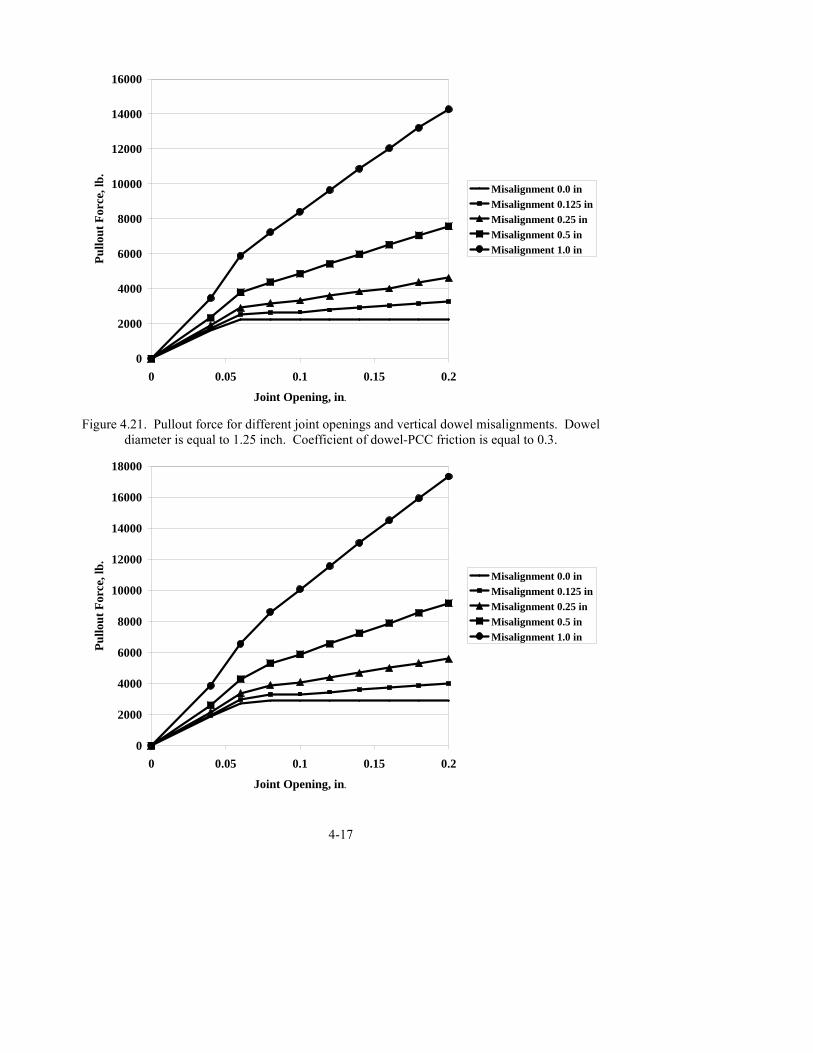
4-17
0
2000
4000
6000
8000
10000
12000
14000
16000
0 0.05 0.1 0.15 0.2
Joint Opening, in.
Pullo
ut F
orce
, lb.
Misalignment 0.0 inMisalignment 0.125 inMisalignment 0.25 inMisalignment 0.5 inMisalignment 1.0 in
Figure 4.21. Pullout force for different joint openings and vertical dowel misalignments. Dowel
diameter is equal to 1.25 inch. Coefficient of dowel-PCC friction is equal to 0.3.
0
2000
4000
6000
8000
10000
12000
14000
16000
18000
0 0.05 0.1 0.15 0.2
Joint Opening, in.
Pullo
ut F
orce
, lb.
Misalignment 0.0 inMisalignment 0.125 inMisalignment 0.25 inMisalignment 0.5 inMisalignment 1.0 in

4-18
Figure 4.22. Pullout force for different joint openings and vertical dowel misalignments. Dowel diameter is equal to 1.5 inch. Coefficient of dowel-PCC friction is equal to 0.3.
0
2000
4000
6000
8000
10000
12000
14000
16000
18000
0 0.05 0.1 0.15 0.2
Joint Opening, in.
Pullo
ut F
orce
, lb. Misalignment 0.0 in
Misalignment 0.125 inMisalignment 0.25 inMisalignment 0.5 inMisalignment 1.0 in
Figure 4.23. Pullout force for different joint openings and vertical dowel misalignments. Dowel
diameter is equal to 1.0 inch. Coefficient of dowel-PCC friction is equal to 0.5.

4-19
0
5000
10000
15000
20000
25000
0 0.05 0.1 0.15 0.2
Joint Opening, in.
Pullo
ut F
orce
, lb.
Misalignment 0.0 inMisalignment 0.125 inMisalignment 0.25 inMisalignment 0.5 inMisalignment 1.0 in
Figure 4.24. Pullout force for different joint openings and vertical dowel misalignments. Dowel
diameter is equal to 1.25 inch. Coefficient of dowel-PCC friction is equal to 0.5.

4-20
0
5000
10000
15000
20000
25000
30000
0 0.05 0.1 0.15 0.2
Joint Opening, in.
Pullo
ut F
orce
, lb.
Misalignment 0.0 inMisalignment 0.125 inMisalignment 0.25 inMisalignment 0.5 inMisalignment 1.0 in
Figure 4.25. Pullout force for different joint openings and vertical dowel misalignments. Dowel
diameter is equal to 1.5 inch. Coefficient of dowel-PCC friction is equal to 0.5.
0
2000
4000
6000
8000
10000
12000
14000
16000
18000
20000
0 0.2 0.4 0.6 0.8 1
Vertical Misalignment, in
Pullo
ut F
orce
, lb
Friction=0.3Friction=0.5
Figure 4.26. Effect of dowel-PCC friction and vertical dowel misalignment on pullout force.
Dowel diameter is equal to 1 in. Joint opening is equal to 0.2 in.

4-21
0
5000
10000
15000
20000
25000
0 0.2 0.4 0.6 0.8 1
Vertical Misalignment, in
Pullo
ut F
orce
, lb
Friction=0.3Friction=0.5
Figure 4.27. Effect of dowel-PCC friction and vertical dowel misalignment on pullout force.
Dowel diameter is equal to 1.25 in. Joint opening is equal to 0.2 in.
0
5000
10000
15000
20000
25000
30000
0 0.2 0.4 0.6 0.8 1
Vertical Misalignment, in
Pullo
ut F
orce
, lb
Friction=0.3Friction=0.5
Figure 4.28. Effect of dowel-PCC friction and vertical dowel misalignment on pullout force.
Dowel diameter is equal to 1.5 in. Joint opening is equal to 0.2 in.

4-22
Figure 4.29. Modification of the finite element model to account for analysis of a single
misaligned dowel.
Spring

4-23
Figure 4.30. Determination of the equivalent spring stiffness.

4-24
0
2000
4000
6000
8000
10000
12000
0 0.05 0.1 0.15 0.2
Joint Opening, in.
Pullo
ut F
orce
, lb.
NoneUniformSingleNonuniform
Figure 4.31. Effect of misalignment uniformity on pullout force magnitude.

5-1
CHAPTER 5 FINITE ELEMENT MODELING OF HORIZONTALLY MISALIGNMENT DOWEL Two models were developed to analyze the effect of horizontal dowel misalignment on joint behavior. A simple 2D model was developed first. To validate and further elaborate findings from that model, a more comprehensive 3D model was also developed. A discussion of the findings from both models is presented below. 2D Finite Element Model of a Horizontally Misaligned Dowel The 2D plane ABAQUS model developed for initial investigation of a horizontally misaligned dowel consists of three parts: one segment models a dowel connecting two other segments which model the PCC of two adjacent slabs (see figures 5.1 and 5.2). The plane stress elements were used to model both the PCC and the dowel. Special friction contact elements were used to model dowel–PCC interaction. The total number of nodes and elements was equal to 3116 and 2801, respectively. The following design parameters were used in the model: • PCC modulus of elasticity = 4,000,000 psi • PCC Poisson’s ratio = 0.15 • PCC coefficient of thermal expansion = 5*10-6 in/in/oF • PCC joint spacing = 15 feet • Dowel modulus of elasticity = 40,000,000 psi • Dowel Poisson’s ratio = 0.3 • Dowel coefficient of thermal expansion = 5*10-6 in/in/oF • Dowel length = 18 inch • Dowel spacing = 12 inch • Coefficient of subgrade reaction = 200 psi/inch • ABAQUS element type - CAX4R The dowel surface was defined as the master surface, and the PCC contact surface was defined as the slave. The length of the PCC segments was equal to half of the joint spacing. Since the 2D model cannot model a circular dowel cross-section, a rectangular one with the effective width and height replaced it. The dowel height and thickness were determined using the same approach as was used for the 2D model of a vertically misaligned dowel. The effective dowel width, bd, was selected to provide equality in the areas of contact surfaces:
2*dbd
π=
where d is the dowel diameter. The effective dowel height, hd, was selected to provide equality in dowel flexural stiffness. This resulted in the following relationship:

5-2
3
4
*16**3
dd b
dh π=
The longitudinal edges of the PCC segments were restrained from transverse movements to simulate restraints from the surrounding PCC and dowels. The horizontal displacements of transverse edges of the PCC fragments simulated the effect of PCC temperature movements. The dowel axis could be aligned or misaligned with the longitudinal axis. An initial contact pressure between the PCC and dowel in the finite element model was introduced by assigning a positive change in the dowel temperature. A series of finite element runs were performed to investigate the influence of magnitude of dowel misalignment. Each analysis was performed in two loading steps. The first step involved increasing the dowel temperature to provide initial contact pressure between the dowels and surrounding PCC. The second step simulated temperature movements of the joint by inducing horizontal displacements of left and right ends of the model up to 0.1 inch with a 0.02 inch increment. This corresponds to joint openings from 0 to 0.2 inch. Figures 5.3, 5.4, and 5.5 present distributions of longitudinal, shear, and normal stresses, respectively, in a perfectly aligned dowel and the surrounding PCC. The stress distributions are symmetrical with respect to the longitudinal axis, and the magnitude of the resulting stresses is relatively low. Figures 5.6, 5.7, and 5.8 present distributions of longitudinal, shear, and normal stresses, respectively, in a misaligned dowel and the surrounding PCC. The dowel misalignment was equal to 1 inch. Dowel misalignment causes significant increases in all components of PCC stress distributions around dowels. Moreover, a significant increase in restraint provided by dowels to the joint opening was observed. Therefore, the researchers preliminarily concluded that horizontal misalignment of dowels may significantly affect joint behavior, and that conclusion led to a decision to perform a comprehensive 3D finite element modeling of horizontal dowel misalignment. Prior to that modeling, however, an additional 2D analysis was performed. It was prompted by an observation that a selection of a PCC segment width equal to half of the dowel spacing may significantly over-restrain PCC segments. Indeed, such restraints provide accurate modeling of a PCC stress state only if all dowels in a joint are misaligned by the same magnitude but neighboring dowels are misaligned in different directions, as shown in figure 5.9. Since it was desirable to isolate the effect of misalignment of a single dowel, it was decided to increase the width of PCC segments to double dowel spacing. A comparison of dowel pullout force for different levels of joint opening and dowel misalignment made for a dowel spacing equal to 12 in from the model with the PCC width equal to the dowel spacing (Model A) and from the model with the PCC width equal to the double dowel spacing (Model B) (see figure 5.10). For large joint openings, both models produce similar pullout forces. However, Model B produced more reasonable pullout forces for smaller joint openings.
5-3
Therefore, double dowel spacing was recommended for PCC segments’ width for 3D modeling. 3D Finite Element Model of a Horizontally Misaligned Dowel The 3D model developed in this study consists of three parts, as shown in figures 5.11, 5.12, and 5.13. One segment models a dowel connecting to other segments, which model the PCC of two adjacent slabs. The height, length, and width of the PCC segments are equal to half the PCC slab thickness, half the joint spacing, and double the dowel spacing, respectively. In the examples considered in this study, the height, length, and width of the PCC segments were equal to 5, 90, and 24 inch, respectively. The bottom surface was supported by the Winkler foundation with k-value equal to 200psi/in. The upper surface was restrained from vertical displacement to model symmetrical behavior. Although in reality stresses and displacement distributions are not exactly symmetrical with respect to the PCC plate mid plane, they are close to symmetrical for the type of loading considered in this study. The dowel axis could be aligned or misaligned with the longitudinal axis. The dowel and PCC segments were connected using the special contact friction elements. An initial contact pressure between the PCC and dowel in the finite element model was introduced by assigning a positive change in the dowel temperature. The total number of nodes and elements in the finite element model were 11488 and 8240, respectively. The execution time for a representative problem was equal to 650 sec of CPU time and up to 14 hours of clock time. The effects of magnitude of horizontal dowel misalignment, dowel–PCC friction, and dowel diameter on dowel behavior were investigated in this study. Each analysis was performed in two loading steps. The first step involved increasing the dowel temperature to provide initial contact pressure between the dowel and surrounding PCC. The second step simulated temperature movements of the joint by inducing horizontal displacements of the left and right ends of the dowel up to 0.1 inch with a 0.02 inch increment. This corresponds to joint openings from 0 to 0.2 inch. Appendix C presents stress distribution in dowels and surrounding PCC for the joint opening equal to 0.2 inch and different levels of dowel misalignment. An increase in dowel misalignment increases both stress magnitude and non-uniformity. For example, for dowel misalignment equals 1 inch, the magnitude of Mises equivalent stresses is likely to exceed PCC shear strength for a significant area around the dowel. This may cause joint failure. A zone of longitudinal stresses exceeding 140 psi occupies the entire dowel length from the site of higher tension. Some longitudinal stresses are much higher. Figure 5.14 presents the distribution of longitudinal PCC stresses along the dowel length for different distances from a dowel. Even 1 inch away from a dowel, some stresses exceed 600 psi. Stress distribution becomes more uniform about 4 inch from the joint, but the PCC tensile stresses are still relatively high.

5-4
Although the results of the 3D analysis appeared to be reasonable and quantitatively agreed with the results of 2D analysis, it was decided to validate the finite element model by performing several runs and with a mesh twice finer than in the runs presented above. The purpose of this activity was to verify that the fineness of the mesh does not affect the results of the analysis. Four cases were considered. The dowel diameter was equal to 1 inch. The PCC–dowel friction coefficient was equal to 0.3. The dowel misalignment was varied from 0.125 to 1 inch. The joint opening was equal to 0.2 inch. Figure 5.15 presents a comparison of longitudinal PCC stress at 1 inch from dowel from analyses performed using regular and fine finite element meshes. Very good agreement is observed between the two stress distributions. Figure 5.16 presents a comparison of total dowel pullout forces obtained for four different cases using regular and fine meshes. Again, good agreement is observed between the results. This verifies that the finite element mesh used in the analysis is sufficiently fine to produce accurate results. Since PCC stress distribution around a dowel may be highly non-uniform, it was decided to select total dowel pullout force as a measure of PCC–dowel resistance to the joint opening. This force is defined as a total normal force in a dowel cross-section located in the middle of the joint and normal to the dowel longitudinal axis. It was found, however, that it is more numerically stable to compute this force as a sum of the normal force in a vertical PCC cross-section located a sufficient distance from a joint. Using the finite model described above, the dowel pullout force was computed for the following input parameters: • Dowel diameter: 1, 1.25, and 1.5 inch. • Coefficient of dowel-PCC friction: 0.3 and 0.5. • Dowel misalignment: 0, 0.125, 0.25, .0.5, and 1 inch. • Joint opening: 0, 0.04, 0.08, 0.12, 0.16, and 0.2 inch. In all cases, dowel length was assigned equal to 18 inch, joint spacing was equal to 15 feet, and modulus of elasticity of PCC and dowel were assumed equal to 4 and 40 million psi, respectively. Figures 5.17, 5.18, and 5.19 present dowel pullout forces for dowel diameters equal to 1, 1.25, and 1.5 inch for a PCC-dowel friction coefficient equal to 0.3. The magnitude of pullout force increases with increases in joint opening and dowel misalignment. Figure 5.20 presents a comparison of pullout forces for the PCC-dowel friction coefficient equal to 0.3 and 0.5 and different levels of misalignment of a 1.25-inch dowel. This figure illustrates that an increase in PCC–dowel friction increases dowel pullout force. Simplified Spring Model Based on the results of this analysis, the following piece-wise linear model for a pullout force as a function of a joint opening was developed:

5-5
inuifuKKinuifuK
PIII
I
06.0)06.0(*06.0*06.0*
>−+≤
=
where P – pullout force u – joint opening, in
KI and KII - dowel pullout stiffness The models for dowel pullout stiffnesses, KI and KII, as functions of horizontal dowel misalignment were developed for each dowel diameter separately. The models resulted in the following equations: Dowel Diameter 1 inch K1=253754 m+1089603 mμ +89852μ , Rs=0.9961 K2=184689 m+1063994 mμ , Rs=0.9972 Dowel Diameter 1.25 inch K1=334913 m+1144525 mμ +109595 ,μ Rs=0.9964 K2=211569 m+1359858 mμ , Rs=0.9971 Dowel Diameter 1.50 inch K1=390761 m+1219439mμ +133063 ,μ Rs=0.9953 K2=234378 m+1868980mμ Rs=0.9972 where
μ - coefficient of PCC-dowel friction. m – relative horizontal misalignment defined as
dLMm =
where M – horizontal misalignment, in Ld – dowel length, in
This model permits efficient analysis of the effect of dowel misalignment on multi-slab system behavior. Limitations of the Analysis This chapter presented the results of investigation of the effect of horizontal dowel misalignment on restraints the dowel exhibits to joint opening. Only one dowel was explicitly included in the finite element model. This model can adequately describe the behavior of uniformly aligned dowels. It was shown in chapter 4, and indirectly confirmed in this chapter, that non-uniformity can have a great effect on joint behavior. Therefore, to provide more accurate joint modeling, at least three dowels should be modeled. Also, PCC–
Comment: Looks like an empty square to me.

5-6
base friction was ignored in this study and should be considered in more sophisticated models.

5-7
Figure 5.1. 2D model of a horizontally misaligned dowel.
Figure 5.2. 2D model of a horizontally misaligned dowel—central fragment.
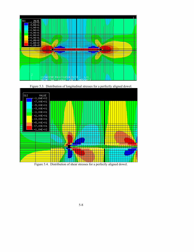
5-8
Figure 5.3. Distribution of longitudinal stresses for a perfectly aligned dowel.
Figure 5.4. Distribution of shear stresses for a perfectly aligned dowel.

5-9
Figure 5.5. Distribution of transverse stresses for a perfectly aligned dowel.
Figure 5.6. Distribution of longitudinal stresses for a misaligned dowel; misalignment is equal to 1 in.

5-10
Figure 5.7. Distribution of shear stresses for a misaligned dowel; misalignment is equal to 1 in.
Figure 5.8. Distribution of transverse stresses for a misaligned dowel; misalignment is equal
to 1 in.

5-11
Figure 5.9. PCC joint with dowels misaligned in different directions.
0
1000
2000
3000
4000
5000
6000
7000
8000
9000
0 0.02 0.04 0.06 0.08 0.1
Displacement, in
Pullo
ut F
orce
, lb
Model A, Misal.= 0.0inModel A, Misal.= 1.0inModel B, Misal.=0.0inModel B, Misal.=1.0in
Figure 5.10. Effect of PCC width and dowel misalignment on pullout force.

5-12
Figure 5.11. 3D model of horizontally misaligned dowel.
Figure 5.12. 3D model of a dowel.

5-13
Figure 5.13. 3D model of a PCC fragment.
Figure 5.14. Distribution of longitudinal PCC stresses for a misaligned dowel with horizontal misalignment 1 in for several distances from the dowel; dowel diameter is equal 1in
0
100
200
300
400
500
600
700
800
900
0 2 4 6 8 10
Distance,in
Lon
gitu
dina
l Str
ess,p
si
y=1.5 iny=3.0 iny=5.5 in

5-14
0
100
200
300
400
500
600
700
800
900
0 2 4 6 8 10
Distance, in
Lon
gitu
dina
l str
ess,
psi
Regular meshFine mesh
Figure 5.15. Comparison of longitudinal PCC stresses obtained using regular and fine finite element mesh; dowel diameter is equal 1 inch.
0
2000
4000
6000
8000
10000
12000
14000
0 2000 4000 6000 8000 10000 12000 14000
Pullout Force, Fine Mesh
Pullo
ut F
orce
, lb.
Reg
ular
Mes
h
Figure 5.16. Comparison of dowel pullout forces caused by joint opening obtained using
regular and fine finite element mesh; dowel diameter is equal 1 inch.

5-15
0
2000
4000
6000
8000
10000
12000
14000
0 0.05 0.1 0.15 0.2
Joint Opening, in.
Pullo
ut F
orce
, lb.
Misalignment 0.0 inMisalignment 0.125 inMisalignment 0.25 inMisalignment 0.5 inMisalignment 1 in
Figure 5.17. Pullout force for different joint openings and horizontal dowel misalignments. Dowel diameter is equal to 1.0 inch. Coefficient of dowel-PCC friction is equal to 0.3.
02000400060008000
1000012000140001600018000
0 0.05 0.1 0.15 0.2
Joint Opening, in.
Pullo
ut F
orce
, lb.
Misalignment 0.0 inMisalignment 0.125 inMisalignment 0.25 inMisalignment 0.5 inMisalignment 1 in
Figure 5.18. Pullout force for different joint openings and horizontal dowel misalignmensts.
Dowel diameter is equal to 1.25 in. Coefficient of dowel-PCC friction is equal to 0.3.

5-16
0
5000
10000
15000
20000
25000
0 0.05 0.1 0.15 0.2
Joint Opening, in.
Pullo
ut F
orce
, lb.
Mialignment 0.0 inMisalignment 0.125 inMisalignment 0.25 inMisalignment 0.5 inMisalignment 1 in
Figure 5.19. Pullout force for different joint openings and horizontal dowel misalignments.
Dowel diameter is equal to 1.5 inch. Coefficient of dowel-PCC friction is equal to 0.3.
0
2000
4000
6000
8000
10000
12000
14000
16000
18000
20000
0 0.2 0.4 0.6 0.8 1
Horizontal Misaligment, in
Pullo
ut F
orce
,lb
Friction=0.3Friction=0.5
Figure 5.20. Effect of dowel-PCC friction and horizontal dowel misalignment on
pullout force. Dowel diameter is equal to 1 inch. Joint opening is equal to 0.2 in.
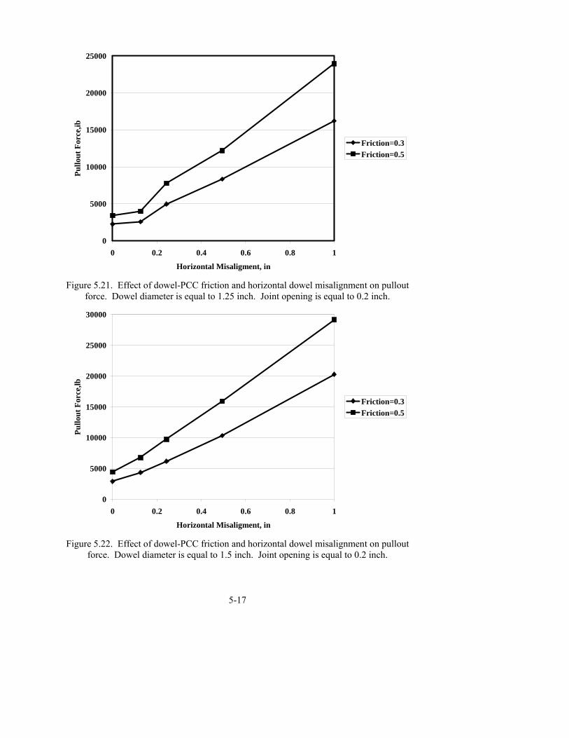
5-17
0
5000
10000
15000
20000
25000
0 0.2 0.4 0.6 0.8 1
Horizontal Misaligment, in
Pullo
ut F
orce
,ib
Friction=0.3Friction=0.5
Figure 5.21. Effect of dowel-PCC friction and horizontal dowel misalignment on pullout
force. Dowel diameter is equal to 1.25 inch. Joint opening is equal to 0.2 inch.
0
5000
10000
15000
20000
25000
30000
0 0.2 0.4 0.6 0.8 1
Horizontal Misaligment, in
Pullo
ut F
orce
,lb
Friction=0.3Friction=0.5
Figure 5.22. Effect of dowel-PCC friction and horizontal dowel misalignment on pullout
force. Dowel diameter is equal to 1.5 inch. Joint opening is equal to 0.2 inch.

6-1
CHAPTER 6 COMBINED SPRING MODEL OF A VERTICALLY
AND HORIZONTALLY MISALIGNED DOWEL The combined effect of vertical and horizontal misalignment was not investigated directly in this study. Moreover, as it was shown in chapters 4 and 5, the effects of both vertical and horizontal misalignments depend not only the misalignment magnitude of a dowel itself but also on the magnitude of the misalignment of adjacent dowels. Therefore, a finite element model with at least three dowels should be used for direct modeling of the combined effect of vertical and horizontal misalignment. Because such modeling could not performed in this study (for lack of time, budget, and hardware), the following simplified procedure was recommended instead. Step 1. Determine horizontal and vertical components of dowel misalignment. Step 2. Estimate oppositely uniform part of vertical misalignment and, using corresponding equations from chapter 4, determine dowel pullout stiffnesses in vertical direction, KIvert and KIIvert. Step 3. Determine dowel pullout stiffnesses in horizontal direction, KIhor and KIIhor, using corresponding equations from chapter 5. Step 4. Determine combined dowel pullout stiffnesses, KIcomb and KIIcomb.
IvertIhorIcomb KKK +=
IIvertIIhorIIcomb KKK += Step 5. If dowels are misaligned uniformly in the horizontal direction, determine combined pullout force using the following equation:
inuifuKKinuifuK
PIIIcomb
Icombcomb 06.0)06.0(*06.0*
06.0*>−+≤
=
where
P – combined pullout force u – joint opening, in If dowels are misaligned non-uniformly in the horizontal direction, a multi-slab analysis should be performed. This analysis will be discussed in chapter 7.

7-1
CHAPTER 7 MULTI-SLAB ANALYSIS OF PCC PAVEMENTS
WITH MISALIGNED DOWELS To evaluate the effect of misalignment of one or more dowels in a multi-slab system on the entire system behavior, a 2D finite element model was developed. The model consisted of three PCC slabs connected with doweled joints. A center slab was modeled as a full-length slab, whereas only half of the right and left slabs were modeled directly because the centers of the right and left slabs were restrained from longitudinal movements (see figure 7.1). The PCC slabs were modeled using 2D plane stress elements. Dowels were modeled using spring elements. The stiffness of those springs was determined using the pullout force-joint opening relationships presented in previous sections. The researchers investigated the effect of dowel misalignment on behavior of 15-feet. long PCC slabs subjected to contraction caused by temperature drops of 200 oF. The following design parameters were used in the model: • PCC modulus of elasticity = 4,000,000 psi • PCC Poisson’s ratio = 0.15 • PCC coefficient of thermal expansion = 5*10-6 in/in/oF • Dowel modulus of elasticity = 40,000,000 psi • Dowel diameter = 1.5 inches. • Dowel Poisson’s ratio = 0.3 • Dowel coefficient of thermal expansion = 5*10-6 in/in/oF • Dowel length = 18 inches. • Dowel spacing = 12 inches. • ABAQUS element type - CPS4R and SPRING2 The following cases were considered: • Case 1. All dowels are perfectly aligned. • Case 2. All dowels are misaligned on the same magnitude but adjacent dowels misaligned in
opposite direction. • Case 3. All dowels in the left joint are perfectly aligned and all dowels in the right joint are
misaligned. • Case 4. One central dowel in the left joint is misaligned and all other dowels are perfectly
aligned. • Case 5. One central dowel in the right joint and one central dowel in the left joint are
misaligned and all other dowels are perfectly aligned. • Case 6. One edge dowel in the left joint is misaligned and all other dowels are perfectly
aligned.

7-2
If a certain dowel was misaligned, the magnitude of misalignment was 1 inch. It should be noted that for the case of a single misaligned dowel, the analysis is conservative since simplified models for oppositely misaligned dowels are used. Figures 7.2 and 7.3 present the stress distribution for Case 1 for the entire system and for a fragment near the joint. The stress distribution is quite uniform, with slight stress concentration near dowels. Figures 7.4 and 7.5 present the stress distribution for Case 2 for the entire system and for a fragment near the joint. The magnitude of stresses both near and far from dowels increases compared to the stresses from Case 1. Figures 7.6 and 7.7 present the stress distribution for Case 3 for the entire system and for a fragment near the left joint. The magnitude of stresses both near and far from dowels are higher than the corresponding stresses from Case 1 but lower than the corresponding stresses from Case 2. Figures 7.8 and 7.9 present the stress distribution for Case 4 for the entire system and for a fragment near the misaligned dowel. There is a significant stress concentration around the misaligned dowel that propagates far from the dowel itself. Nevertheless, the magnitudes of the stresses are not as high as the magnitude of stresses near the misaligned dowels in Cases 2 and 3. Figures 7.10 and 7.11 present the stress distribution for Case 5 for the entire system and for a fragment near the misaligned dowel. There is a significant stress concentration around the misaligned dowel that propagates far from the dowel itself. Moreover, the magnitudes of the stresses near misaligned dowels are even higher than the corresponding stresses from Case 2. Finally, figures 7.12 and 7.13 present the stress distribution for Case 6 for the entire system and for a fragment near the misaligned dowel. There is a significant stress concentration at the edge where the misaligned dowel is located. However, the magnitudes of the stresses near misaligned dowels are lower than the corresponding stresses from Case 4. Table 7.1 summarizes the data for all cases. Cases 1 and 2 exhibited very similar joint openings. On the other hand, Case 3 resulted in significant differences in joint opening between joints with aligned and misaligned dowels. A joint with misaligned dowels remained tight, whereas a joint with aligned dowels was wide open. This wide opening may result in excessive joint faulting. This analysis leads to the conclusion that dowel misalignment may significantly affect joint opening and cause excessive PCC stresses near joints.

7-3
Table 7.1. Representative joint openings due to a temperature drop of 200 oF.
Joint opening, inch Case Left joint Right joint
1 0.1764 0.1764 2 0.1657 0.1657 3 0.3125 0.0388 4 0.1124 0.2373 5 0.1717 0.1717 6 0.2225 0.2882
Figure 7.1. 2D model of a multi-slab system.

7-4
Figure 7.2. Distribution of longitudinal PCC stresses in Case 1.
Figure 7.3. Distribution of longitudinal PCC stresses near dowels in Case 1.

7-5
Figure 7.4. Distribution of longitudinal PCC stresses in Case 2.
Figure 7.5. Distribution of longitudinal PCC stresses near dowels in Case 2.

7-6
Figure 7.6. Distribution of longitudinal PCC stresses in Case 3.
Figure 7.7. Distribution of longitudinal PCC stresses near dowels in Case 3.

7-7
Figure 7.8. Distribution of longitudinal PCC stresses in Case 4.
Figure 7.9. Distribution of longitudinal PCC stresses near the misaligned dowel in Case 4.
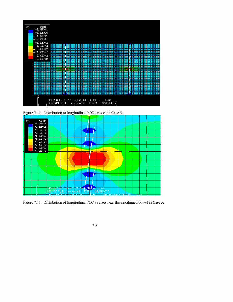
7-8
Figure 7.10. Distribution of longitudinal PCC stresses in Case 5.
Figure 7.11. Distribution of longitudinal PCC stresses near the misaligned dowel in Case 5.

7-9
Figure 7.12. Distribution of longitudinal PCC stresses in Case 6.
Figure 7.13. Distribution of longitudinal PCC stresses near the misaligned
dowel in Case 6.

8-1
CHAPTER 8 CONCLUSIONS, RECOMMENDATIONS AND FUTURE RESEARCH NEEDS
The study reported herein included the development of several finite element models using a commercial finite element package—ABAQUS. A comprehensive PCC–dowel interaction model was developed and calibrated/validated using the results of a pullout test. Based on the preliminary analysis, the following conclusions can be drawn:
1. Non-uniform dowel misalignment leads to significant increases in PCC stresses in the
area surrounding dowels.
2. A single misaligned dowel resulted in PCC stresses higher than in the case of uniformly misaligned dowels but lower than in the case of oppositely misaligned dowels, assuming that all other parameters are the same. Non-uniform dowel misalignment (single misaligned dowel and oppositely misaligned dowel) causes greater restraint to horizontal movements at the PCC joint than uniform misalignment. On the other hand, a single misaligned dowel causes less restraint than oppositely misaligned dowels.
3. The analysis of multiple slabs suggests that if several consecutive joints are locked up, a
uniform drop in temperature may cause significant longitudinal stresses and lead to premature cracking if acting together with heavy axle loading and slab curling. On the other hand, if only one joint has misaligned dowels and all neighboring joints do not, then the adjacent joints may open widely and prevent the joint with misaligned dowels from forming properly. This may lead to an increase in effective joint spacing and, in turn, to random cracking near the joint.
4. The level of non-uniformity of dowel misalignment is very important.
5. To model random dowel misalignment properly; at least three dowels should be modeled.
6. Even in the case of oppositely misaligned dowels, misalignment up to 1/8 inch did not
cause significant restraints on joint behavior.
7. A more comprehensive model should be used to verify and, if necessary, modify these recommendations.
The analysis of misaligned dowels showed that uniform vertical misalignment did not cause significant resistance to joint horizontal movements. At the same time, non-uniform misalignment may cause joint lock-up and premature pavement failure. Since the use of automatic dowel bar inserters may result in such non-uniform misalignment, this effect should be further investigated. Future studies should include comprehensive laboratory and field-testing, as well as finite element modeling of a fragment of a joint with at least three dowels.

8-2
Although the magnitude and uniformity of dowel misalignment are significant factors affecting joint performance, its interaction with other factors should be considered. A brief discussion of those factors is presented below.
• Dowel–PCC friction. As was shown in chapters 4 and 5, an increase in friction magnifies
the effect of dowel misalignment. On the other hand, a reduction of friction may raise the allowable misalignment tolerance level.
• Dowel diameter. The interaction of dowel diameter and dowel misalignment was not
investigated in this study. To investigate this effect properly, more information is required regarding the dependence of the friction coefficient and initial contact pressure on dowel diameter.
• PCC thickness. The effect of PCC thickness was not investigated in this study. Indirect
observations lead to the preliminary conclusion that an increase in PCC thickness leads to an increase in pullout force; however, it should also decrease PCC stresses due to dowel misalignment. More investigation is needed.
• PCC/base/subgrade friction. An increase in PCC/base/subgrade friction reduces
maximum joint opening and, therefore, reduces the effect of dowel misalignment. In this study, this effect was ignored.
• Coefficient of thermal expansion. An increase in the coefficient of thermal expansion
increases joint opening, and, as a result, increases the effect of dowel misalignment. Therefore, a PCC pavement with a low coefficient of thermal expansion (high quality PCC aggregate) may tolerate much higher levels of dowel misalignment than a PCC pavement with a high coefficient of thermal expansion (for example, built from recycled aggregates).
• Climatic conditions. Greater variations in PCC temperature cause wider joint openings
and increase the effect of dowel misalignment. On the other hand, a pavement built in a moderate climate may tolerate a higher level of dowel misalignment.
• PCC set temperature. A higher PCC set temperature will result in wider joint opening in
the winter and, therefore, increase the effect of dowel misalignment. In this study, several comprehensive finite element models were developed for a single dowel misaligned vertically or horizontally. Those models provide accurate modeling of joints with all dowels misaligned uniformly or joints with adjacent dowels misaligned by the same magnitude but in different directions. To more accurately investigate the effect of random dowel misalignment, it is recommended to generalize the models to include at least three dowels, each of which is misaligned independently from the others in both vertical and horizontal directions. The model developed in this study will be crucial for the development of dowel misalignment tolerance levels for automatic dowel bar inserters.

8-3
The finite element model for multi-slab analysis clearly demonstrates that the presence of dowel misalignment can significantly affect joint opening and the subsequent stress development. However, the model assumes that all joints have been properly formed. It is recommended to develop a finite element model of joint formation that accounts for the presence of misaligned dowels. Such a model permits accurate evaluation of the magnitude of dowel misalignment, which prevents joints from proper formation. Future Research Needs To verify the finite element models developed in this study and to provide proper inputs to them, the following laboratory tests are recommended: 1. Modified pullout test 2. Combined pullout/bending test 3. Generalized pullout test Modified Pullout Test To provide better information about the dowel–PCC interaction condition, it is recommended to conduct a pullout test (figure 8.1) with a modified test protocol. Instead of measuring the pullout force every 0.1 inch of dowel displacement, the pullout force will be recorded every 0.005 inch from 0 to 0.1 inch and every 0.05 inch from 0.1 to 0.3 inch. This test will allow reliable determination of the elastic tolerance parameter in the dowel–PCC interaction model. It is recommended to conduct this test for dowel diameters of 1.25 and 1.5 inches. Combined Pullout/Bending Test As stated in this report, the results of the pullout test permit the backcalculation of only one of two dowel–PCC interaction model parameters: friction coefficient or initial dowel/PCC contact pressure. To determine the dowel/PCC friction coefficient, a combined pullout/bending test can be conducted (see figure 8.2). If the dowels are pulled out with different angles, the vertical component of the dowel end displacement should cause additional dowel–PCC contact pressure. By comparing the pullout forces obtained from different angles, the friction coefficient can be determined. It is recommended to conduct this test for 1.25-inch dowels and three vertical-to-horizontal displacement ratios: 0, .05, and 0.1 inch. Conduct Generalized Pullout Test

8-4
Through numerical modeling, it was discovered in this study that both magnitude of dowel misalignment and misalignment non-uniformity (variation of misalignment from dowel to dowel in a joint) affect joint behavior. To validate this finding, a generalized pullout test is proposed. A fragment of a joint with three dowels will be modeled (see figure 8.3). The following scenarios will be considered: • All three dowels are perfectly aligned. • All three dowels are horizontally misaligned. • All three dowels are vertically misaligned. • All three dowels are horizontally misaligned, but the center dowel is misaligned in different
direction. • All three dowels are vertically misaligned, but the center dowel is misaligned in different
direction. • Two side dowels are aligned but the center dowel is horizontally misaligned • Two side dowels are aligned but the center dowel is vertically misaligned This test will be conducted for 1.25-in dowels and four levels of misalignment: 0.125 inch, 0.25 inch, 0.5 inch, and 1.0 inch. The results of this test will help to answer the following questions: • What is the effect of dowel misalignment on joint resistance to opening? • Is there any difference in the effects of horizontal and vertical misalignment? Should they be
limited to the same or different values? • What is the effect of non-uniform misalignment in vertical and horizontal directions? These tests will also provide crucial information for validation of the finite element model and development of dowel misalignment tolerance guidelines.

8-5
P
u
Figure 8.1. Pullout test.
P
u
Pbend
Figure 8.2. Combined pullout/bending test.

8-6
u
P P
Figure 8.3. Generalized pullout test.

9-1
CHAPTER 9 REFERENCES
Bock, B.T. and Okamoto, P., (1989), Evaluation of Dowel Placement Using a Dowel Bar Inserter, Proceedings of the 4th International Conference on Concrete Pavement Design and Rehabilitation, April.
Darter, M.I. (1977). Design of Zero-Maintenance Plain Jointed Concrete Pavement: Vol. I - Development of Design Procedures. Federal Highway Administration, Report No. FHWA -RD-77-111, Washington, D.C., June. Darter, M.I., K.T. Hall, and C. Kuo. (1995). Support Under Portland Cement Concrete Pavements. NCHRP Report 372. Washington, DC. Hammons M.I. (1997). Development of an Analysis System for Discontinuities in Rigid Airfield Pavements. FAA, Technical Report GL-97-3. Hibbitt, Karlsson, and Sorensen, Inc. (1998). ABAQUS, Finite Element Computer Program. Version 5.6. Hoerner T.E., M.I. Darter, L. Khazanovich, L. Titus-Glover, and K.L. Smith. (2000). “Improved Prediction Models for PCC Pavement Performance-Related Specifications, Volume I: Final Report,” Report: FHWA-RD-00-130. McLean, VA: Federal Highway Administration. Khazanovich, L., M. Darter, R. Bartlett. (1997). Common Characteristics of Good and Poorly Performing PCC Pavements. Washington, DC: Federal Highway Administration. Khazanovich, L., H.T. Yu, S. Rao, K. Galasova, E. Shats, and R. Jones. (2000). ISLAB2000—Finite Element Analysis Program for Rigid and Composite Pavements. User’s Guide. ERES Consultants, Champaign, Illinois. Ross, F.T., and Rutkowski, T.S. (1989). A Designed System of Load Transfer Dowels for Joints in PCC Pavement, Final Report, Wisconsin Department of Transportation. Tayabji, S.D. (1988). “Dowel Placement Tolerances for Concrete Pavements,” Transportation Research Record 1062, pp.47-54. Tayabji, S.D., and Okamoto, P.1988). “Field Evaluation of Dowel Placement in Concrete Pavements,” Transportation Research Record 1062, pp.101-109. Yu, H.T., M.I. Darter, K.D. Smith, J. Jiang, and L. Khazanovich. (1996). Performance of Concrete Pavements, vol III - Improving Concrete Pavement Performance. Report No. FHWA-RD-95-111. Washington, DC: Federal Highway Administration.

9-2
Zaghloul, S. and T. White (1993). “Nonlinear Dynamic Analysis of Concrete Pavements,” Proceedings, Fifth International Conference on Concrete Pavement Design and Rehabilitation, Vol 1., West Lafayette, IN: Purdue University, pp. 277-292.

A-1
APPENDIX A INTRODUCTION TO THE FINITE ELEMENT METHOD
This brief introduction to the theoretical background of the finite element method was extracted from class notes developed by Professor Yijun Liu at the University of Cincinnati. The research team appreciates Professor Liu’s permission to use these materials. The rest of the class notes can be found at http://urbana.mie.uc.edu/yliu/FEM-525/FEM-525.htm. Determining stresses, strains, and deflections in pavement structures is a complex engineering problem. Closed form (simple expression) analytical solutions are invaluable to a point, but they do not have the flexibility to analyze many pavement structures, including PCC slab–dowel interaction. The introduction of computers in the middle of the 20th century opened the door for a more flexible way of solving structural problems—the finite element method (FEM). In the FEM, the system to be analyzed is represented by an assemblage of discrete bodies called “finite elements.” These elements are interconnected at specific locations called “nodes.” Within each element, actual displacements are approximated using special functions called “displacement functions” or “shape functions.” These functions relate displacements at each point within the element with the element nodes. For each element, a relationship between the generalized node displacements and the generalized forces applied at the nodes is developed using the principle of virtual work or some other approach. This relationship is expressed in the form of an element stiffness matrix: [k] {d} = {p} where
[k] – element stiffness matrix [d] – generalized nodal displacements [p] – generalized nodal forces
The element stiffness matrix incorporates geometrical and material properties of one element. The overall stiffness matrix, [K], is then formatted by superimposing the individual element stiffness matrices using the element connectivity properties of the structure. [K] is used to solve a system of equations relating applied forces and displacements within the structure: [K] {D} = {P} where
[K] – global stiffness matrix {D}– generalized nodal displacements for the whole system {P}– applied nodal for forces for the whole system
Solution of this system gives the displacements within the system: {D}=[K]-1 {P}

A-2
Using nodal displacements and shape functions, stresses and strains can be found for each element.

B-1
APPENDIX B STRESS DISTRIBUTIONS FOR VERTICALLY
MISALIGNED DOWEL This appendix presents stress distributions in vertically misaligned dowels and the surrounding PCC for joint openings equal to 0.2 in and different levels of dowel misalignment. For these cases, the friction coefficient was 0.3, which corresponds to pullout PCC shear stress equal to 60 psi for a perfectly aligned 1.25 inch dowel. Figures B.1 through B.12 present stress distributions for a 1 inch dowel, figures B.13 through B.24 present stress distributions for distributions for a 1.25 inch dowel, and figures B.25 through B.36 present stress distributions for a 1.5 inch dowel. The level of misalignment is varied from 0.125 to 1 inch. It is assumed that adjacent dowels in a joint are misaligned by the same magnitude but in opposite direction. For each combination of dowel diameter and dowel misalignment, distributions of Mises shear stresses, pressure stresses, and longitudinal stresses are provided. Misalignments as small as 0.125 inch cause stress concentration zones in the new PCC joint. An increase in dowel misalignment up to 0.25 inch leads to a more pronounced change in the character of PCC stress distribution around a dowel, as seen in figures B.4 through B.6, B.16 through B.18, and B.28 through B.30. A zone of stress concentration of longitudinal stresses occupies the entire dowel length. Nevertheless, the magnitude of PCC stresses is still relatively low. A further increase in dowel misalignment does not change the character of stress distribution but causes a significant increase in stress magnitude, as seen in figures B.7 through B.12, B.18 through B.24, and B.31 through B.36.

B-2
Figure B.1. Distribution of Mises equivalent shear stresses for a misaligned dowel;
dowel diameter is equal 1 in, vertical misalignment is equal to 0.125 in.
Figure B.2. Distribution of equivalent pressure for a misaligned dowel; dowel diameter is equal 1 in, vertical misalignment is equal to 0.125 in.

B-3
Figure B.3. Distribution of longitudinal stresses for a misaligned dowel; dowel diameter is equal 1 in, vertical misalignment is equal to 0.125 in.
Figure B.4. Distribution of Mises equivalent shear stresses for a misaligned dowel; dowel diameter is equal 1 in, vertical misalignment is equal to 0.25 in.

B-4
Figure B.5. Distribution of equivalent pressure for a misaligned dowel; dowel diameter is equal 1 in, vertical misalignment is equal to 0.25 in.
Figure B.6. Distribution of longitudinal stresses for a misaligned dowel; dowel diameter is equal 1 in, vertical misalignment is equal to 0.25 in.

B-5
Figure B.7. Distribution of Mises equivalent shear stresses for a misaligned dowel;
dowel diameter is equal 1 in, vertical misalignment is equal to 0.5 in.
Figure B.8. Distribution of equivalent pressure for a misaligned dowel; dowel diameter is
equal 1 in, vertical misalignment is equal to 0.5 in.

B-6
Figure B.9. Distribution of longitudinal stresses for a misaligned dowel; dowel diameter is equal
1 in, vertical misalignment is equal to 0.5 in.
Figure B.10. Distribution of Mises equivalent shear stresses for a misaligned dowel; dowel
diameter is equal 1 in, vertical misalignment is equal to 1 in.

B-7
Figure B.11. Distribution of equivalent pressure for a misaligned dowel; dowel diameter is equal 1 in, vertical misalignment is equal to 1 in.
Figure B.12. Distribution of longitudinal stresses for a misaligned dowel; dowel diameter is equal 1 in, vertical misalignment is equal to 1 in.

B-8
Figure B.13. Distribution of Mises equivalent shear stresses for a misaligned dowel; dowel diameter is equal 1.25 in, vertical misalignment is equal to 0.125 in.
Figure B.14. Distribution of equivalent pressure for a misaligned dowel; dowel diameter is equal
1.25 in, vertical misalignment is equal to 0.125 in.

B-9
Figure B.15. Distribution of longitudinal stresses for a misaligned dowel; dowel diameter is
equal 1.25 in, vertical misalignment is equal to 0.125 in.
Figure B.16. Distribution of Mises equivalent shear stresses for a misaligned dowel; dowel
diameter is equal 1.25 in, vertical misalignment is equal to 0.25 in.
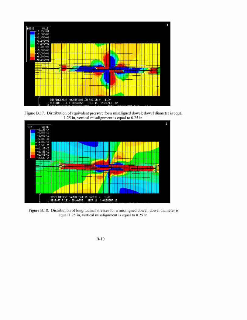
B-10
Figure B.17. Distribution of equivalent pressure for a misaligned dowel; dowel diameter is equal
1.25 in, vertical misalignment is equal to 0.25 in.
Figure B.18. Distribution of longitudinal stresses for a misaligned dowel; dowel diameter is
equal 1.25 in, vertical misalignment is equal to 0.25 in.

B-11
Figure B.19. Distribution of Mises equivalent shear stresses for a misaligned dowel;
dowel diameter is equal 1.25 in, vertical misalignment is equal to 0.5 in.
Figure B.20. Distribution of equivalent pressure for a misaligned dowel; dowel diameter is equal
1.25 in, vertical misalignment is equal to 0.5 in.

B-12
Figure B.21. Distribution of longitudinal stresses for a misaligned dowel; dowel diameter is
equal 1.25 in, vertical misalignment is equal to 0.5 in.
Figure B.22. Distribution of Mises equivalent shear stresses for a misaligned dowel; dowel diameter is equal 1.25 in, vertical misalignment is equal to 1 in.
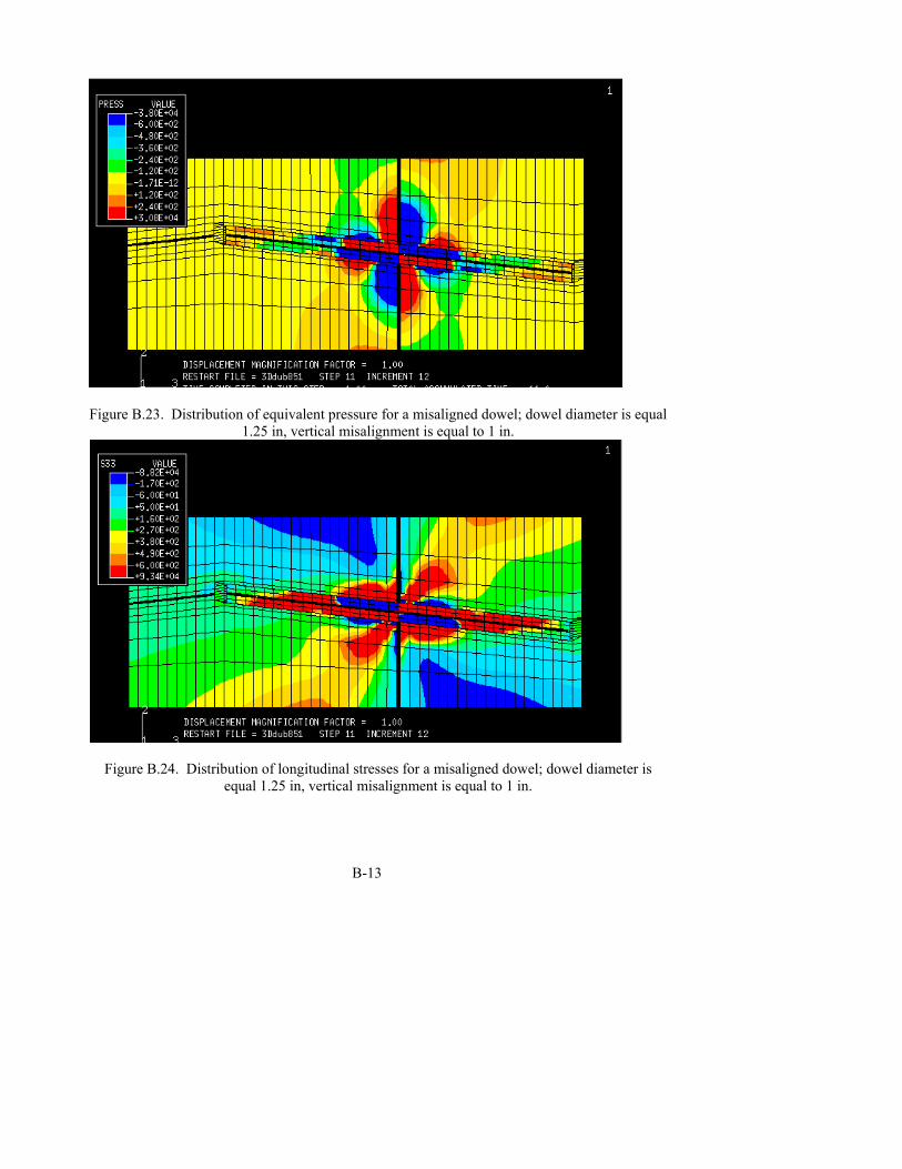
B-13
Figure B.23. Distribution of equivalent pressure for a misaligned dowel; dowel diameter is equal
1.25 in, vertical misalignment is equal to 1 in.
Figure B.24. Distribution of longitudinal stresses for a misaligned dowel; dowel diameter is
equal 1.25 in, vertical misalignment is equal to 1 in.

B-14
Figure B.25. Distribution of Mises equivalent shear stresses for a misaligned dowel; dowel
diameter is equal 1.5 in, vertical misalignment is equal to 0.125 in.
Figure B.26. Distribution of equivalent pressure for a misaligned dowel; dowel diameter is equal 1.5 in, vertical misalignment is equal to 0.125 in.

B-15
Figure B.27. Distribution of longitudinal stresses for a misaligned dowel; dowel diameter is equal 1.5 in, vertical misalignment is equal to 0.125 in.
Figure B.28. Distribution of Mises equivalent shear stresses for a misaligned dowel; dowel
diameter is equal 1.5 in, vertical misalignment is equal to 0.25 in.

B-16
Figure B.29. Distribution of equivalent pressure for a misaligned dowel; dowel diameter is equal 1.5 in, vertical misalignment is equal to 0.25 in
Figure B.30. Distribution of longitudinal stresses for a misaligned dowel; dowel diameter is equal 1.5 in, vertical misalignment is equal to 0.25 in.

B-17
Figure B.31. Distribution of Mises equivalent shear stresses for a misaligned dowel; dowel
diameter is equal 1.5 in, vertical misalignment is equal to 0.5 in.
Figure B.32. Distribution of equivalent pressure for a misaligned dowel; dowel diameter is equal 1.5 in, vertical misalignment is equal to 0.5 in

B-18
Figure B.33. Distribution of longitudinal stresses for a misaligned dowel; dowel diameter is equal 1.5 in, vertical misalignment is equal to 0.5 in.
Figure B.34. Distribution of Mises equivalent shear stresses for a misaligned dowel; dowel
diameter is equal 1.5 in, vertical misalignment is equal to 1 in.

B-19
Figure B.35. Distribution of equivalent pressure for a misaligned dowel; dowel diameter is equal 1.5 in, vertical misalignment is equal to 1 in
Figure B.36. Distribution of longitudinal stresses for a misaligned dowel; dowel diameter is equal 1.5 in, vertical misalignment is equal to 1 in.

C-1
APPENDIX C STRESS DISTRIBUTIONS FOR HORIZONTALLY
MISALIGNED DOWEL
This appendix presents stress distributions in horizontally misaligned dowels and the surrounding PCC for joint openings equal to 0.2 inch and different levels of dowel misalignment. For these cases, the friction coefficient was 0.3, which corresponds to pullout PCC shear stress equal to 60 psi for a perfectly aligned 1.25-inch dowel. Figures C.1 through C.3 present stress distributions in a perfectly aligned 1.25-inch dowel. Figures C.4 through C.15 present stress distributions for a 1.25-in misaligned dowel, and figures C.16 through C.27 present stress distributions for 1.5-inch misaligned dowel. The level of misalignment is varied from 0.125 to 1 inch. For each combination of dowel diameter and dowel misalignment, distributions of Mises shear stresses, pressure stresses, and longitudinal stresses are provided. Figures C.1 through C.3 present distributions of equivalent Mises stresses, equivalent pressure stresses, and longitudinal stresses in a perfectly aligned dowel and the surrounding PCC. The stress distributions are symmetrical with respect to the slab mid-depth plane, and the magnitude of the resulting stresses is relatively low. Longitudinal PCC stresses are uniformly distributed along the dowel length except for small zones of stress concentration near dowel ends. For misaligned dowels, the patterns observed are similar to those observed for vertical displacement (see appendix B). Although misalignment as small as 0.125 inch causes stress concentration zones in the new PCC joint, only slight non-uniformity of longitudinal stresses is observed in figures C.6 and C.18. An increase in dowel misalignment up to 0.25 inch leads to a more pronounced change in the character of PCC stress distribution around a dowel, as seen in figures C.7 through C.9 and C.19 through C.21. A zone of stress concentration of longitudinal stresses occupies the entire dowel length. Nevertheless, the magnitude of PCC stresses is still relatively low. A further increase in dowel misalignment does not change the character of stress distribution but causes a significant increase in stress magnitude, as seen in figures C.13 through C.15 and C.22 through C.27.

C-2
Figure C.1. Distribution of Mises equivalent shear stresses for a perfectly aligned dowel;
dowel diameter is equal 1.25 in.
Figure C.2. Distribution of equivalent pressure stresses for a perfectly aligned dowel;
dowel diameter is equal 1.25 in.

C-3
Figure C.3. Distribution of longitudinal stresses for a perfectly aligned dowel; dowel
diameter is equal 1.25 in.
Figure C.4. Distribution of Mises equivalent shear stresses for a misaligned dowel with horizontal misalignment 0.125 in; dowel diameter is equal 1.25 in.

C-4
Figure C.5. Distribution of equivalent pressure stresses for a misaligned dowel with
horizontal misalignment 0.125 in; dowel diameter is equal 1.25 in.
Figure C.6. Distribution of longitudinal stresses for a misaligned dowel with
horizontal misalignment 0.125 in; dowel diameter is equal 1.25 in.

C-5
Figure C.7. Distribution of Mises equivalent shear stresses for a misaligned dowel with
horizontal misalignment 0.25 in; dowel diameter is equal 1.25 in.
Figure C.8. Distribution of equivalent pressure stresses for a misaligned dowel with
horizontal misalignment 0.25 in; dowel diameter is equal 1.25 in.
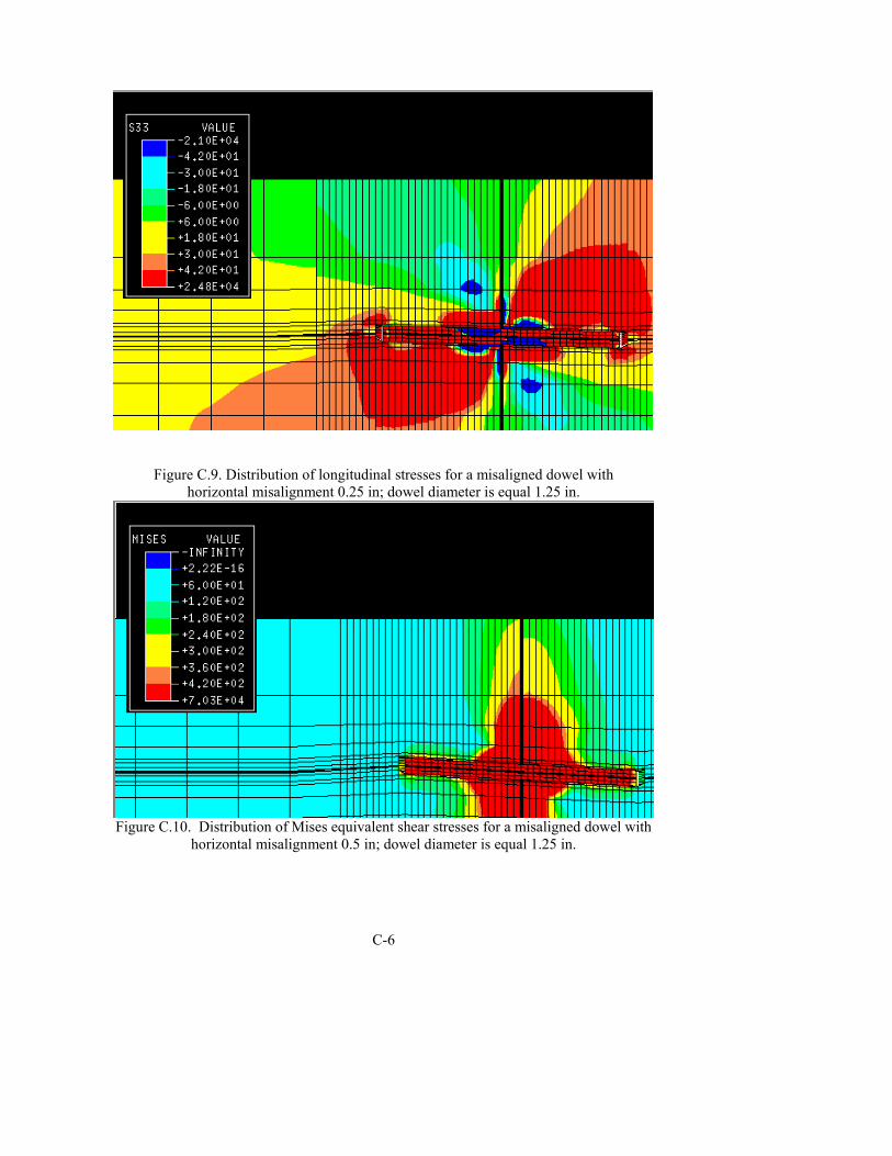
C-6
Figure C.9. Distribution of longitudinal stresses for a misaligned dowel with horizontal misalignment 0.25 in; dowel diameter is equal 1.25 in.
Figure C.10. Distribution of Mises equivalent shear stresses for a misaligned dowel with
horizontal misalignment 0.5 in; dowel diameter is equal 1.25 in.

C-7
Figure C.11. Distribution of equivalent pressure stresses for a misaligned dowel with horizontal misalignment 0.5 in; dowel diameter is equal 1.25 in.
Figure C.12. Distribution of longitudinal stresses for a misaligned dowel with
horizontal misalignment 0.5 in; dowel diameter is equal 1.25 in.

C-8
Figure C.13. Distribution of Mises equivalent shear stresses for a misaligned dowel with horizontal misalignment 1 in; dowel diameter is equal 1.25 in.
Figure C.14. Distribution of equivalent pressure stresses for a misaligned dowel with
horizontal misalignment 1 in; dowel diameter is equal 1.25 in.

C-9
Figure C.15. Distribution of longitudinal stresses for a misaligned dowel with horizontal misalignment 1 in; dowel diameter is equal 1.25 in.
Figure C.16. Distribution of Mises equivalent shear stresses for a misaligned dowel with
horizontal misalignment 0.125 in; dowel diameter is equal 1.5 in.

C-10
Figure C.17. Distribution of equivalent pressure stresses for a misaligned dowel with
horizontal misalignment 0.125 in; dowel diameter is equal 1.5 in.
Figure C.18. Distribution of longitudinal stresses for a misaligned dowel with
horizontal misalignment 0.125 in; dowel diameter is equal 1.5 in.

C-11
Figure C.19. Distribution of Mises equivalent shear stresses for a misaligned dowel with
horizontal misalignment 0.25 in; dowel diameter is equal 1.5 in.
Figure C.20. Distribution of equivalent pressure stresses for a misaligned dowel with
horizontal misalignment 0.25 in; dowel diameter is equal 1.5 in.

C-12
Figure C.21. Distribution of longitudinal stresses for a misaligned dowel with
horizontal misalignment 0.25 in; dowel diameter is equal 1.5 in.
Figure C.22. Distribution of Mises equivalent shear stresses for a misaligned dowel with
horizontal misalignment 0.5 in; dowel diameter is equal 1.5 in.

C-13
Figure C.23. Distribution of equivalent pressure stresses for a misaligned dowel with
horizontal misalignment 0.5 in; dowel diameter is equal 1.5 in.
Figure C.24. Distribution of longitudinal stresses for a misaligned dowel with
horizontal misalignment 0.5 in; dowel diameter is equal 1.5 in.

C-14
Figure C.25. Distribution of Mises equivalent shear stresses for a misaligned dowel with
horizontal misalignment 1 in; dowel diameter is equal 1.5 in.
Figure C.26. Distribution of equivalent pressure stresses for a misaligned dowel with
horizontal misalignment 1 in; dowel diameter is equal 1.5 in.

C-15
Figure C.27. Distribution of longitudinal stresses for a misaligned dowel with horizontal
misalignment 1 in; dowel diameter is equal 1.5 in

D-1
APPENDIX D. TYPICAL ABAQUS INPUT FILES Problem 1. Axisymmetric Pullout Test Model • PCC modulus of elasticity = 4,000,000 psi • PCC Poisson’s ratio = 0.15 • PCC coefficient of thermal expansion = 0.000005 in./in./oF • PCC joint spacing = 15 ft. • dowel modulus of elasticity = 40,000,000 psi • dowel Poisson’s ratio = 0.3 • dowel coefficient of thermal expansion = 0.000005 in./in./oF • dowel length = 18 in. • dowel spacing = 12 in. • Coefficient of subgrade reaction = 200 psi • ABAQUS element type - CAX4R • Maximum axis displacement =0.1 in. *HEADING Axisymmetric pullout test model *PREPRINT,MODEL=no,HISTORY=NO,ECHO=YES ** ................. NODES STEEL *NODE 1,0.,37.25 41,0.,27.25 *ngen,nset=line1 1,41,1 *NODE 247,0.625,37.25 287,0.625,27.25 *ngen,nset=line2 247,287,1 *nfill,nset=NSTEEL line1,line2,6,41 ** NODES CONCRETE *NODE 288,0.625,36.25 324,0.625,27.25 *ngen,nset=line3 288,324,1 *NODE 1916,5.,36.25 1952,5.,27.25 *ngen,nset=line4 1916,1952,1 *nfill line3,line4,44,37 *NODE 1953,0.,27. 2007,0.,0. *ngen,nset=line5

D-2
1953,2007,1 *NODE 4703,5.,27. 4757,5.,0. *ngen,nset=line6 4703,4757,1 *nfill,NSET=NCON3 line5,line6,50,55 *NSET,NSET=outline,generate 5,251,82 ** ** ...............ELEMENTS STEEL *ELEMENT,TYPE=CAX4R,ELSET=ST1 1,3,85,83,1 *ELGEN,ELSET=ST1 1,20,2,1,2,82,20 *ELEMENT,TYPE=CAX4R,ELSET=ST2 201,167,249,247,165 *ELGEN,ELSET=ST2 201,20,2,1 ** ...............ELEMENTS CONCRETE *ELEMENT,TYPE=CAX4R,ELSET=CON1 241,290,327,325,288 *ELGEN,ELSET=CON1 241,18,2,1 *ELEMENT,TYPE=CAX4R,ELSET=CON2 278,327,364,362,325 389,438,512,510,436 759,808,956,954,806 1499,1548,1733,1731,1546 1684,1733,1918,1916,1731 277,2283,2338,361,324 314,2338,2393,398,361 351,2393,2448,435,398 388,2448,2503,472,435 462,2503,2613,546,472 536,2613,2723,620,546 610,2723,2833,694,620 684,2833,2943,768,694 758,2943,3053,842,768 906,3053,3273,990,842 1054,3273,3493,1138,990 1202,3493,3713,1286,1138 1350,3713,3933,1434,1286 1498,3933,4153,1582,1434 1683,4153,4428,1767,1582 1868,4428,4703,1952,1767 *ELGEN,ELSET=CON2 278,18,2,1,3,37,37 389,18,2,2,5,74,74 759,18,2,4,5,148,148 1499,18,2,5 1684,18,2,5 *ELEMENT,TYPE=CAX4R,ELSET=CON3 1869,1954,2009,2008,1953 1881,1968,2023,2020,1965 2409,2504,2614,2613,2503

D-3
2421,2518,2628,2625,2515 2949,3054,3274,3273,3053 2961,3068,3288,3285,3065 4029,4154,4429,4428,4153 4041,4168,4443,4440,4165 4703,4429,4704,4703,4428 4715,4443,4718,4715,4440 *ELGEN,ELSET=CON3 1869,12,1,1,10,55,54 1881,14,3,1,10,55,54 2409,12,1,1,5,110,54 2421,14,3,1,5,110,54 2949,12,1,1,5,220,54 2961,14,3,1,5,220,54 4029,12,1,1 4041,14,3,1 4703,12,1,1 4715,14,3,1 *elset,ELSET=ALLEL,generate 205,277 *SURFACE DEFINITION, NAME=CONCR CON1, S4 *SURFACE DEFINITION, NAME=STE ST2, S2 *CONTACT PAIR, INTERACTION=FRIC2 CONCR, STE **STE,CONCR *SURFACE INTERACTION, NAME=FRIC2 1.0 *FRICTION, TAUMAX=0,SLIP TOLERANCE=0.1 .3 *SURFACE BEHAVIOR, NO SEPARATION *MATERIAL,NAME=concr1 *ELASTIC 4.E6,0.15 *MATERIAL,NAME=concr2 *ELASTIC 4.E3,0.15,0. 4.E6,0.15,0.01 *MATERIAL,NAME=dowel *ELASTIC 4.E7,0.3 *EXPANSION 5.E-6 *SOLID SECTION,MATERIAL=concr1,ELSET=CON1 *SOLID SECTION,MATERIAL=concr1,ELSET=CON2 *SOLID SECTION,MATERIAL=concr2,ELSET=CON3 *SOLID SECTION,MATERIAL=dowel,ELSET=ST1 *SOLID SECTION,MATERIAL=dowel,ELSET=ST2 *RESTART,WRITE,FREQUENCY=999 ** ** ...................STEP1 *STEP,NLGEOM,INC=100 *STATIC .05,1.,.001,1. ** ...................TEMPERATURE *TEMPERATURE

D-4
NSTEEL, 15.0 NCON3,0. *BOUNDARY line1,1 line5,1 5,2 *node print,NSET=outline,FREQUENCY=999 U,RF *el print,elset=ALLEL,FREQUENCY=999 S *END STEP ** ...................STEP2 *STEP,NLGEOM,INC=100 *STATIC .05,1.,.001,1. ** ...................TEMPERATURE *TEMPERATURE NSTEEL, 1.0 NCON3,0.01 *BOUNDARY line1,1 line5,1 5,2 *node print,NSET=outline,FREQUENCY=999 U,RF *el print,elset=ALLEL,FREQUENCY=999 S *END STEP ** STEP3 *STEP,NLGEOM,INC=100 *STATIC .05,1.,.001,1. *BOUNDARY 5,2,2,0.02 4757,2 *node print,NSET=outline,FREQUENCY=999 U,RF *el print,elset=ALLEL,FREQUENCY=999 S *END STEP ** STEP4 *STEP,NLGEOM,INC=100 *STATIC .05,1.,.001,1. *BOUNDARY 5,2,2,0.04 *node print,NSET=outline,FREQUENCY=999 U,RF *el print,elset=ALLEL,FREQUENCY=999 S *END STEP ** STEP5 *STEP,NLGEOM,INC=100 *STATIC .05,1.,.001,1. *BOUNDARY 5,2,2,0.06

D-5
*node print,NSET=outline,FREQUENCY=999 U,RF *el print,elset=ALLEL,FREQUENCY=999 S *END STEP ** STEP6 *STEP,NLGEOM,INC=100 *STATIC .05,1.,.001,1. *BOUNDARY 5,2,2,0.08 *node print,NSET=outline,FREQUENCY=999 U,RF *el print,elset=ALLEL,FREQUENCY=999 S *END STEP ** STEP7 *STEP,NLGEOM,INC=100 *STATIC .05,1.,.001,1. *BOUNDARY 5,2,2,0.10 *node print,NSET=outline,FREQUENCY=999 U,RF *el print,elset=ALLEL,FREQUENCY=999 S *END STEP

D-6
Problem 2. 2D Model of Pullout Test • PCC modulus of elasticity = 4,000,000 psi • PCC Poisson’s ratio = 0.15 • PCC coefficient of thermal expansion = 0.000005 in./in./oF • Far field PCC modulus of elasticity = 10,000,000 psi • PCC joint spacing = 15 ft • dowel modulus of elasticity = 40,000,000 psi • dowel Poisson’s ratio = 0.3 • dowel coefficient of thermal expansion = 0.000005 in./in./oF • dowel length = 18 in. • dowel spacing = 12 in. • Coefficient of subgrade reaction = 200 psi • ABAQUS element type - CPS4R • Maximum axis displacement =0.1 in. *HEADING 2-D Pullout test model *PREPRINT,MODEL=no,HISTORY=NO,ECHO=yes ** ................. NODES STEEL *NODE 1,0.,37.25 41,0.,27.25 *ngen,nset=line1 1,41,1 *NODE 247,0.433,37.25 287,0.433,27.25 *ngen,nset=line2 247,287,1 *nfill,nset=NSTEEL line1,line2,6,41 ** NODES CONCRETE *NODE 288,0.433,36.25 324,0.433,27.25 *ngen,nset=line3 288,324,1 *NODE 1916,5.,36.25 1952,5.,27.25 *ngen,nset=line4 1916,1952,1 *nfill line3,line4,44,37 *NODE 1953,0.,27. 2007,0.,0. *ngen,nset=line5 1953,2007,1

D-7
*NODE 4703,5.,27. 4757,5.,0. *ngen,nset=line6 4703,4757,1 *nfill line5,line6,50,55 *NODE 4758,0.,36.25 4794,0.,27.25 *ngen,nset=line7 4758,4794,1 *NODE 4869,3.75,36.25 4905,3.75,27.25 *ngen,nset=line8 4869,4905,1 *nfill line7,line8,3,37 *NODE 4906,0.,27. 4960,0.,0. *ngen,nset=line9 4906,4960,1 *NODE 5071,3.75,27. 5125,3.75,0. *ngen,nset=line10 5071,5125,1 *nfill line9,line10,3,55 *NODE 5126,0.,-.5 5131,1.,-.5 *ngen,nset=line11 5126,5131,1 *node 5140,5.,-.5 *ngen,nset=line12 5131,5140,1 *NODE 5141,0.,-1. 5146,2.,-1. *ngen,nset=line13 5141,5146,1 *NODE 5152,5.,-1. *ngen,nset=line14 5146,5152,1 *NODE 5153,0.,-3. 5163,5.,-3. *ngen,nset=line15 5153,5163,1 *NODE 5329,0.,-54. 5339,5.,-54.

D-8
*ngen,nset=line16 5329,5339,1 *nfill line15,line16,16,11 *NODE 5340,0.,-.5 5359,1.25,-.5 5378,2.5,-.5 5397,3.75,-.5 5341,0.,-1. 5360,1.25,-1. 5379,2.5,-1. 5398,3.75,-1 5342,0.,-3. 5399,3.75,-3. 5358,0.,-54. 5415,3.75,-54. *ngen,nset=line17 5342,5358,1 *ngen,nset=line18 5399,5415,1 *nfill line17,line18,3,19 *NSET,NSET=outline,generate 247,287 *NSET,NSET=NDISP,generate 4,250,41 50004,50250,41 *nset,nset=ndisp1 4,50004 *NSET,NSET=NSTEEL5,generate 50001,50287 *NSET,NSET=NREAL,generate 1,4757 5126,5339 *NSET,NSET=NADD,generate 4758,5125 5340,5415 *NCOPY, CHANGE NUMBER=50000, OLD SET=NREAL, REFLECT=LINE, NEW SET=NREAL2 -0.036,0,0, -0.036, 100,0 *NCOPY, CHANGE NUMBER=50000, OLD SET=NADD, REFLECT=LINE, NEW SET=NADD2 -0.036,0,0, -0.036, 100,0 *nfill,nset=NCON4 line5,line6,50,55 *NSET,NSET=NCON54,generate 5126,5339 ** ** ...............ELEMENTS STEEL *ELEMENT,TYPE=CPS4R,ELSET=ST1 1,2,43,42,1 *ELGEN,ELSET=ST1 1,40,1,1,5,41,40 *ELEMENT,TYPE=CPS4R,ELSET=ST2 201,207,248,247,206 *ELGEN,ELSET=ST2 201,40,1,1

D-9
*ELEMENT,TYPE=CPS4R,ELSET=ST0 5229,50002,2,1,50001 *ELGEN,ELSET=ST0 5229,40,1,1 ** ...............ELEMENTS CONCRETE *ELEMENT,TYPE=CPS4R,ELSET=CON1 241,289,326,325,288 *ELGEN,ELSET=CON1 241,36,1,1 *ELEMENT,TYPE=CPS4R,ELSET=CON2 278,326,363,362,325 389,437,511,510,436 759,807,955,954,806 1499,1547,1732,1731,1546 1684,1732,1917,1916,1731 277,2283,2338,361,324 314,2338,2393,398,361 351,2393,2448,435,398 388,2448,2503,472,435 462,2503,2613,546,472 536,2613,2723,620,546 610,2723,2833,694,620 684,2833,2943,768,694 758,2943,3053,842,768 906,3053,3273,990,842 1054,3273,3493,1138,990 1202,3493,3713,1286,1138 1350,3713,3933,1434,1286 1498,3933,4153,1582,1434 1683,4153,4428,1767,1582 1868,4428,4703,1952,1767 *ELGEN,ELSET=CON2 278,36,1,1,3,37,37 389,36,1,2,5,74,74 759,36,1,4,5,148,148 1499,36,1,5 1684,36,1,5 *ELEMENT,TYPE=CPS4R,ELSET=CON3 1869,1954,2009,2008,1953 1881,1968,2023,2020,1965 2409,2504,2614,2613,2503 2421,2518,2628,2625,2515 2949,3054,3274,3273,3053 2961,3068,3288,3285,3065 4029,4154,4429,4428,4153 4041,4168,4443,4440,4165 4299,4429,4704,4703,4428 4311,4443,4718,4715,4440 *ELGEN,ELSET=CON3 1869,12,1,1,10,55,54 1881,14,3,1,10,55,54 2409,12,1,1,5,110,54 2421,14,3,1,5,110,54 2949,12,1,1,5,220,54 2961,14,3,1,5,220,54 4029,12,1,1 4041,14,3,1

D-10
4299,12,1,1 4311,14,3,1 *ELEMENT,TYPE=CPS4R,ELSET=CON4 4569,4759,4796,4795,4758 4680,4870,1917,1916,4869 4605,4906,4961,4831,4794 4642,4961,5016,4868,4831 4679,5016,5071,4905,4868 4716,5071,4703,1952,4905 4717,4907,4962,4961,4906 4879,5072,4704,4703,5071 *ELGEN,ELSET=CON4 4569,36,1,1,3,37,37 4680,36,1,1 4717,54,1,1,3,55,54 4879,54,1,1 *ELEMENT,TYPE=CPS3,ELSET=CON3A 4933,5126,2062,2007 4936,5127,2172,2117 4939,5128,2282,2227 4942,5129,2392,2337 4945,5130,2502,2447 4948,5131,2667,2557 4951,5132,2887,2777 4934,5126,5127,2062 4937,5127,5128,2172 4940,5128,5129,2282 4943,5129,5130,2392 4946,5130,5131,2502 4949,5131,5132,2667 4952,5132,5133,2887 4935,5127,2117,2062 4938,5128,2227,2172 4941,5129,2337,2282 4944,5130,2447,2392 4947,5131,2557,2502 4950,5132,2777,2667 4953,5133,2997,2887 4954,5133,3107,2997 4955,5133,5134,3107 4956,5134,3327,3107 4957,5134,5135,3327 4958,5135,3547,3327 4964,5141,5127,5126 4967,5142,5129,5128 4970,5143,5131,5130 4965,5141,5142,5127 4968,5142,5143,5129 4971,5143,5144,5131 4966,5142,5128,5127 4969,5143,5130,5129 4972,5144,5132,5131 4981,5153,5142,5141 4982,5153,5154,5142 4983,5154,5143,5142 *ELEMENT,TYPE=CPS4R,ELSET=CON3B 4959,5135,5136,3767,3547

D-11
4960,5136,5137,3987,3767 4961,5137,5138,4207,3987 4962,5138,5139,4482,4207 4963,5139,5140,4757,4482 4973,5144,5145,5133,5132 4984,5154,5155,5144,5143 4993,5164,5165,5154,5153 *ELGEN,ELSET=CON3B 4973,8,1,1 4984,9,1,1 4993,10,1,1,16,11,10 *ELEMENT,TYPE=CPS4R,ELSET=CON4A 5153,5340,5359,5015,4960 5172,5359,5378,5070,5015 5191,5378,5397,5125,5070 5154,5341,5360,5359,5340 5210,5397,5140,4757,5125 5211,5398,5152,5140,5397 5212,5399,5163,5152,5398 5213,5400,5174,5163,5399 5214,5401,5185,5174,5400 5215,5402,5196,5185,5401 5216,5403,5207,5196,5402 5217,5404,5218,5207,5403 5218,5405,5229,5218,5404 5219,5406,5240,5229,5405 5220,5407,5251,5240,5406 5221,5408,5262,5251,5407 5222,5409,5273,5262,5408 5223,5410,5284,5273,5409 5224,5411,5295,5284,5410 5225,5412,5306,5295,5411 5226,5413,5317,5306,5412 5227,5414,5328,5317,5413 5228,5415,5339,5328,5414 *ELGEN,ELSET=CON4A 5154,18,1,1,3,19,19 *ELEMENT,TYPE=CPS4R,ELSET=CON30 5269,51954,1954,1953,51953 5281,51968,1968,1965,51965 5323,55126,5126,2007,52007 5324,55141,5141,5126,55126 5325,55153,5153,5141,55141 5326,55164,5164,5153,55153 *ELGEN,ELSET=CON30 5269,12,1,1 5281,14,3,3 5326,16,11,1 *ELEMENT,TYPE=CPS4R,ELSET=CON40 5342,54759,4759,4758,54758 5378,54906,4906,4794,54794 5379,54907,4907,4906,54906 5433,55340,5340,4960,54960 5434,55341,5341,5340,55340 *ELGEN,ELSET=CON40 5342,36,1,1 5379,54,1,1

D-12
5434,18,1,1 *elset,ELSET=ALLEL,generate 201,240 50201,50240 *elset, elset=ereal,generate 1,4568 4933,5152 *elset, elset=eadd,generate 4569,4932 5153,5228 *elset,elset=elfo,generate 1684,1864,5 4299,4324 4963, 4963 4980, 4980 4992,5152,10 4680,4717 4879,4932 5210,5228 *elcopy, old set=CON1,new set=CON51, element shift=50000, shift nodes=50000, reflect *elcopy, old set=CON2,new set=CON52, element shift=50000, shift nodes=50000, reflect *elcopy, old set=CON3,new set=CON53, element shift=50000, shift nodes=50000, reflect *elcopy, old set=CON3a,new set=CON53a, element shift=50000, shift nodes=50000, reflect *elcopy, old set=CON3b,new set=CON53b, element shift=50000, shift nodes=50000, reflect *elcopy, old set=CON4,new set=CON54, element shift=50000, shift nodes=50000, reflect *elcopy, old set=CON4a,new set=CON54a, element shift=50000, shift nodes=50000, reflect *elcopy, old set=st1,new set=st51, element shift=50000, shift nodes=50000, reflect *elcopy, old set=st2,new set=st52, element shift=50000, shift nodes=50000, reflect *elset, elset=ALLREAL,generate 4,40 44,80 84,120 124,160 164,200 204,4568 4933,5152 50004,50040 50044,50080 50084,50120 50124,50160 50164,50200 50204,54568 54933,55152 5232,5280 5281,5320,3 5323,5341 *elset, elset=ALLADD,generate 4569,4932

D-13
5153,5228 54569,54932 55153,55228 ** first contact pair *SURFACE DEFINITION, NAME=CONCR CON1, S4 *SURFACE DEFINITION, NAME=STE ST2, S2 *CONTACT PAIR, INTERACTION=FRIC2 CONCR, STE **STE,CONCR *SURFACE INTERACTION, NAME=FRIC2 1.885 *FRICTION, TAUMAX=0,SLIP TOLERANCE=0.1 .3 *SURFACE BEHAVIOR, NO SEPARATION ** contact pair 2 *SURFACE DEFINITION, NAME=CONCR5 CON51, S1 *SURFACE DEFINITION, NAME=STE5 ST52, S3 *CONTACT PAIR, INTERACTION=FRIC2 CONCR5, STE5 *MATERIAL,NAME=concr1 *ELASTIC 1.E8,0.15 *MATERIAL,NAME=concr2 *ELASTIC 4.E6,0.15,0. 1.E8,0.15,.01 *MATERIAL,NAME=concr4 *ELASTIC 1.E8,0.15 *MATERIAL,NAME=dowel *ELASTIC 4.E7,0.3 *EXPANSION 5.E-6 *SOLID SECTION,MATERIAL=concr1,ELSET=CON1 1.885 *SOLID SECTION,MATERIAL=concr1,ELSET=CON2 1.885 *SOLID SECTION,MATERIAL=concr2,ELSET=CON3 1.885 *SOLID SECTION,MATERIAL=concr4,ELSET=CON4 10. *SOLID SECTION,MATERIAL=concr2,ELSET=CON3A 1.885 *SOLID SECTION,MATERIAL=concr2,ELSET=CON3B 1.885 *SOLID SECTION,MATERIAL=concr4,ELSET=CON4A 10. *SOLID SECTION,MATERIAL=concr2,ELSET=CON30 1.885 *SOLID SECTION,MATERIAL=concr4,ELSET=CON40 10. *SOLID SECTION,MATERIAL=dowel,ELSET=ST1

D-14
1.885 *SOLID SECTION,MATERIAL=dowel,ELSET=ST2 1.885 *SOLID SECTION,MATERIAL=concr1,ELSET=CON51 1.885 *SOLID SECTION,MATERIAL=concr1,ELSET=CON52 1.885 *SOLID SECTION,MATERIAL=concr2,ELSET=CON53 1.885 *SOLID SECTION,MATERIAL=concr4,ELSET=CON54 10. *SOLID SECTION,MATERIAL=concr2,ELSET=CON53A 1.885 *SOLID SECTION,MATERIAL=concr2,ELSET=CON53B 1.885 *SOLID SECTION,MATERIAL=concr4,ELSET=CON54A 10. *SOLID SECTION,MATERIAL=dowel,ELSET=ST51 1.885 *SOLID SECTION,MATERIAL=dowel,ELSET=ST52 1.885 *SOLID SECTION,MATERIAL=dowel,ELSET=ST0 1.885 *FOUNDATION elfo, F2, 200 *RESTART,WRITE,FREQUENCY=999 ** ** ...................STEP1 *STEP,NLGEOM,INC=100 *STATIC .05,1.,.001,1. ** ...................TEMPERATURE *TEMPERATURE NSTEEL, 100.0 NSTEEL5, 100.0 NCON4, 0. NCON54, 0. *BOUNDARY NDISP1,2 5339,2 55339,2 *node print,NSET=outline,FREQUENCY=999 U,RF *el print,elset=ALLEL,FREQUENCY=999 S *END STEP ** ...................STEP2 *STEP,NLGEOM,INC=100 *STATIC .05,1.,.001,1. ** ...................CHANGE MODULUS *TEMPERATURE NCON4, .01 NCON54, .01 *BOUNDARY NDISP1,2 *node print,NSET=outline,FREQUENCY=999

D-15
U,RF *el print,elset=ALLEL,FREQUENCY=999 S *END STEP ** STEP3 *STEP,NLGEOM,INC=100 *STATIC .05,1.,.001,1. *BOUNDARY NDISP1,2,2,0.02 *node print,NSET=outline,FREQUENCY=999 U,RF *el print,elset=ALLEL,FREQUENCY=999 S *END STEP ** STEP4 *STEP,NLGEOM,INC=100 *STATIC .05,1.,.001,1. *BOUNDARY NDISP1,2,2,0.04 *node print,NSET=outline,FREQUENCY=999 U,RF *el print,elset=ALLEL,FREQUENCY=999 S *END STEP ** STEP5 *STEP,NLGEOM,INC=100 *STATIC .05,1.,.001,1. *BOUNDARY NDISP1,2,2,0.06 *node print,NSET=outline,FREQUENCY=999 U,RF *el print,elset=ALLEL,FREQUENCY=999 S *END STEP ** STEP6 *STEP,NLGEOM,INC=100 *STATIC .05,1.,.001,1. *BOUNDARY NDISP1,2,2,0.08 *node print,NSET=outline,FREQUENCY=999 U,RF *el print,elset=ALLEL,FREQUENCY=999 S *END STEP ** STEP7 *STEP,NLGEOM,INC=100 *STATIC .05,1.,.001,1. *BOUNDARY NDISP1,2,2,0.1 *node print,NSET=outline,FREQUENCY=999 U,RF *el print,elset=ALLEL,FREQUENCY=999

D-16
S *END STEP

D-17
Problem 3. 2D Vertical Dowel Misalignment Model • PCC modulus of elasticity = 4,000,000 psi • PCC Poisson’s ratio = 0.15 • PCC coefficient of thermal expansion = 0.000005 in./in./oF • Far field PCC modulus of elasticity = 10,000,000 psi • PCC joint spacing = 15 ft • dowel modulus of elasticity = 40,000,000 psi • dowel Poisson’s ratio = 0.3 • dowel coefficient of thermal expansion = 0.000005 in./in./oF • dowel length = 18 in. • dowel spacing = 12 in. • Coefficient of subgrade reaction = 200 psi • ABAQUS element type - CPS4R • Maximum axis displacement =0.1 in. • Maximum vertical displacement =0.02 in. *HEADING 2-D vertical misalignment model *PREPRINT,MODEL=no,HISTORY=NO,ECHO=yes ** ................. NODES STEEL *NODE 1,0.,37.25 41,0.,27.25 *ngen,nset=line1 1,41,1 *NODE 247,0.433,37.25 287,0.433,27.25 *ngen,nset=line2 247,287,1 *nfill,nset=NSTEEL line1,line2,6,41 ** NODES CONCRETE *NODE 288,0.433,36.25 324,0.433,27.25 *ngen,nset=line3 288,324,1 *NODE 1916,5.,36.25 1952,5.,27.25 *ngen,nset=line4 1916,1952,1 *nfill line3,line4,44,37 *NODE 1953,0.,27. 2007,0.,0. *ngen,nset=line5

D-18
1953,2007,1 *NODE 4703,5.,27. 4757,5.,0. *ngen,nset=line6 4703,4757,1 *nfill line5,line6,50,55 *NODE 4758,0.,36.25 4794,0.,27.25 *ngen,nset=line7 4758,4794,1 *NODE 4869,3.75,36.25 4905,3.75,27.25 *ngen,nset=line8 4869,4905,1 *nfill line7,line8,3,37 *NODE 4906,0.,27. 4960,0.,0. *ngen,nset=line9 4906,4960,1 *NODE 5071,3.75,27. 5125,3.75,0. *ngen,nset=line10 5071,5125,1 *nfill line9,line10,3,55 *NODE 5126,0.,-.5 5131,1.,-.5 *ngen,nset=line11 5126,5131,1 *node 5140,5.,-.5 *ngen,nset=line12 5131,5140,1 *NODE 5141,0.,-1. 5146,2.,-1. *ngen,nset=line13 5141,5146,1 *NODE 5152,5.,-1. *ngen,nset=line14 5146,5152,1 *NODE 5153,0.,-3. 5163,5.,-3. *ngen,nset=line15 5153,5163,1 *NODE 5329,0.,-54.
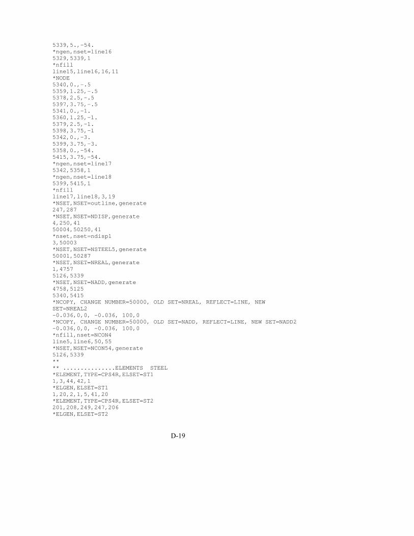
D-19
5339,5.,-54. *ngen,nset=line16 5329,5339,1 *nfill line15,line16,16,11 *NODE 5340,0.,-.5 5359,1.25,-.5 5378,2.5,-.5 5397,3.75,-.5 5341,0.,-1. 5360,1.25,-1. 5379,2.5,-1. 5398,3.75,-1 5342,0.,-3. 5399,3.75,-3. 5358,0.,-54. 5415,3.75,-54. *ngen,nset=line17 5342,5358,1 *ngen,nset=line18 5399,5415,1 *nfill line17,line18,3,19 *NSET,NSET=outline,generate 247,287 *NSET,NSET=NDISP,generate 4,250,41 50004,50250,41 *nset,nset=ndisp1 3,50003 *NSET,NSET=NSTEEL5,generate 50001,50287 *NSET,NSET=NREAL,generate 1,4757 5126,5339 *NSET,NSET=NADD,generate 4758,5125 5340,5415 *NCOPY, CHANGE NUMBER=50000, OLD SET=NREAL, REFLECT=LINE, NEW SET=NREAL2 -0.036,0,0, -0.036, 100,0 *NCOPY, CHANGE NUMBER=50000, OLD SET=NADD, REFLECT=LINE, NEW SET=NADD2 -0.036,0,0, -0.036, 100,0 *nfill,nset=NCON4 line5,line6,50,55 *NSET,NSET=NCON54,generate 5126,5339 ** ** ...............ELEMENTS STEEL *ELEMENT,TYPE=CPS4R,ELSET=ST1 1,3,44,42,1 *ELGEN,ELSET=ST1 1,20,2,1,5,41,20 *ELEMENT,TYPE=CPS4R,ELSET=ST2 201,208,249,247,206 *ELGEN,ELSET=ST2

D-20
201,20,2,1 *ELEMENT,TYPE=CPS4R,ELSET=ST0 5229,50003,3,1,50001 *ELGEN,ELSET=ST0 5229,20,2,1 ** ...............ELEMENTS CONCRETE *ELEMENT,TYPE=CPS4R,ELSET=CON1 241,290,327,325,288 *ELGEN,ELSET=CON1 241,18,2,1 *ELEMENT,TYPE=CPS4R,ELSET=CON2 278,327,364,362,325 389,438,512,510,436 759,808,956,954,806 1499,1548,1733,1731,1546 1684,1733,1918,1916,1731 277,2283,2338,361,324 314,2338,2393,398,361 351,2393,2448,435,398 388,2448,2503,472,435 462,2503,2613,546,472 536,2613,2723,620,546 610,2723,2833,694,620 684,2833,2943,768,694 758,2943,3053,842,768 906,3053,3273,990,842 1054,3273,3493,1138,990 1202,3493,3713,1286,1138 1350,3713,3933,1434,1286 1498,3933,4153,1582,1434 1683,4153,4428,1767,1582 1868,4428,4703,1952,1767 *ELGEN,ELSET=CON2 278,18,2,1,3,37,37 389,18,2,1,5,74,37 759,18,2,1,5,148,37 1499,18,2,1 1684,18,2,1 *ELEMENT,TYPE=CPS4R,ELSET=CON3 1869,1954,2009,2008,1953 1881,1968,2023,2020,1965 2409,2504,2614,2613,2503 2421,2518,2628,2625,2515 2949,3054,3274,3273,3053 2961,3068,3288,3285,3065 4029,4154,4429,4428,4153 4041,4168,4443,4440,4165 4299,4429,4704,4703,4428 4311,4443,4718,4715,4440 *ELGEN,ELSET=CON3 1869,12,1,1,10,55,54 1881,14,3,1,10,55,54 2409,12,1,1,5,110,54 2421,14,3,1,5,110,54 2949,12,1,1,5,220,54 2961,14,3,1,5,220,54 4029,12,1,1

D-21
4041,14,3,1 4299,12,1,1 4311,14,3,1 *ELEMENT,TYPE=CPS4R,ELSET=CON4 4569,4759,4796,4795,4758 4680,4870,1917,1916,4869 4605,4906,4961,4831,4794 4642,4961,5016,4868,4831 4679,5016,5071,4905,4868 4716,5071,4703,1952,4905 4717,4907,4962,4961,4906 4879,5072,4704,4703,5071 *ELGEN,ELSET=CON4 4569,36,1,1,3,37,37 4680,36,1,1 4717,54,1,1,3,55,54 4879,54,1,1 *ELEMENT,TYPE=CPS3,ELSET=CON3A 4933,5126,2062,2007 4936,5127,2172,2117 4939,5128,2282,2227 4942,5129,2392,2337 4945,5130,2502,2447 4948,5131,2667,2557 4951,5132,2887,2777 4934,5126,5127,2062 4937,5127,5128,2172 4940,5128,5129,2282 4943,5129,5130,2392 4946,5130,5131,2502 4949,5131,5132,2667 4952,5132,5133,2887 4935,5127,2117,2062 4938,5128,2227,2172 4941,5129,2337,2282 4944,5130,2447,2392 4947,5131,2557,2502 4950,5132,2777,2667 4953,5133,2997,2887 4954,5133,3107,2997 4955,5133,5134,3107 4956,5134,3327,3107 4957,5134,5135,3327 4958,5135,3547,3327 4964,5141,5127,5126 4967,5142,5129,5128 4970,5143,5131,5130 4965,5141,5142,5127 4968,5142,5143,5129 4971,5143,5144,5131 4966,5142,5128,5127 4969,5143,5130,5129 4972,5144,5132,5131 4981,5153,5142,5141 4982,5153,5154,5142 4983,5154,5143,5142 *ELEMENT,TYPE=CPS4R,ELSET=CON3B

D-22
4959,5135,5136,3767,3547 4960,5136,5137,3987,3767 4961,5137,5138,4207,3987 4962,5138,5139,4482,4207 4963,5139,5140,4757,4482 4973,5144,5145,5133,5132 4984,5154,5155,5144,5143 4993,5164,5165,5154,5153 *ELGEN,ELSET=CON3B 4973,8,1,1 4984,9,1,1 4993,10,1,1,16,11,10 *ELEMENT,TYPE=CPS4R,ELSET=CON4A 5153,5340,5359,5015,4960 5172,5359,5378,5070,5015 5191,5378,5397,5125,5070 5154,5341,5360,5359,5340 5210,5397,5140,4757,5125 5211,5398,5152,5140,5397 5212,5399,5163,5152,5398 5213,5400,5174,5163,5399 5214,5401,5185,5174,5400 5215,5402,5196,5185,5401 5216,5403,5207,5196,5402 5217,5404,5218,5207,5403 5218,5405,5229,5218,5404 5219,5406,5240,5229,5405 5220,5407,5251,5240,5406 5221,5408,5262,5251,5407 5222,5409,5273,5262,5408 5223,5410,5284,5273,5409 5224,5411,5295,5284,5410 5225,5412,5306,5295,5411 5226,5413,5317,5306,5412 5227,5414,5328,5317,5413 5228,5415,5339,5328,5414 *ELGEN,ELSET=CON4A 5154,18,1,1,3,19,19 *ELEMENT,TYPE=CPS4R,ELSET=CON30 5269,51954,1954,1953,51953 5281,51968,1968,1965,51965 5323,55126,5126,2007,52007 5324,55141,5141,5126,55126 5325,55153,5153,5141,55141 5326,55164,5164,5153,55153 *ELGEN,ELSET=CON30 5269,12,1,1 5281,14,3,3 5326,16,11,1 *ELEMENT,TYPE=CPS4R,ELSET=CON40 5342,54759,4759,4758,54758 5378,54906,4906,4794,54794 5379,54907,4907,4906,54906 5433,55340,5340,4960,54960 5434,55341,5341,5340,55340 *ELGEN,ELSET=CON40 5342,36,1,1
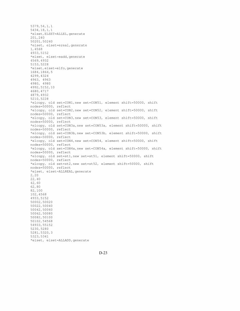
D-23
5379,54,1,1 5434,18,1,1 *elset,ELSET=ALLEL,generate 201,240 50201,50240 *elset, elset=ereal,generate 1,4568 4933,5152 *elset, elset=eadd,generate 4569,4932 5153,5228 *elset,elset=elfo,generate 1684,1864,5 4299,4324 4963, 4963 4980, 4980 4992,5152,10 4680,4717 4879,4932 5210,5228 *elcopy, old set=CON1,new set=CON51, element shift=50000, shift nodes=50000, reflect *elcopy, old set=CON2,new set=CON52, element shift=50000, shift nodes=50000, reflect *elcopy, old set=CON3,new set=CON53, element shift=50000, shift nodes=50000, reflect *elcopy, old set=CON3a,new set=CON53a, element shift=50000, shift nodes=50000, reflect *elcopy, old set=CON3b,new set=CON53b, element shift=50000, shift nodes=50000, reflect *elcopy, old set=CON4,new set=CON54, element shift=50000, shift nodes=50000, reflect *elcopy, old set=CON4a,new set=CON54a, element shift=50000, shift nodes=50000, reflect *elcopy, old set=st1,new set=st51, element shift=50000, shift nodes=50000, reflect *elcopy, old set=st2,new set=st52, element shift=50000, shift nodes=50000, reflect *elset, elset=ALLREAL,generate 2,20 22,40 42,60 62,80 82,100 102,4568 4933,5152 50002,50020 50022,50040 50042,50060 50062,50080 50082,50100 50102,54568 54933,55152 5230,5280 5281,5320,3 5323,5341 *elset, elset=ALLADD,generate

D-24
4569,4932 5153,5228 54569,54932 55153,55228 ** first contact pair *SURFACE DEFINITION, NAME=CONCR CON1, S4 *SURFACE DEFINITION, NAME=STE ST2, S2 *CONTACT PAIR, INTERACTION=FRIC2 CONCR, STE **STE,CONCR *SURFACE INTERACTION, NAME=FRIC2 1.885 *FRICTION, TAUMAX=0,SLIP TOLERANCE=0.1 .3 *SURFACE BEHAVIOR, NO SEPARATION ** contact pair 2 *SURFACE DEFINITION, NAME=CONCR5 CON51, S1 *SURFACE DEFINITION, NAME=STE5 ST52, S3 *CONTACT PAIR, INTERACTION=FRIC2 CONCR5, STE5 *MATERIAL,NAME=concr1 *ELASTIC 4.E6,0.15 *MATERIAL,NAME=concr2 *ELASTIC 4.E3,0.15,0. 1.E8,0.15,.01 *MATERIAL,NAME=concr4 *ELASTIC 1.E8,0.15 *MATERIAL,NAME=dowel *ELASTIC 4.E7,0.3 *EXPANSION 5E-6 *SOLID SECTION,MATERIAL=concr1,ELSET=CON1 1.885 *SOLID SECTION,MATERIAL=concr1,ELSET=CON2 1.885 *SOLID SECTION,MATERIAL=concr2,ELSET=CON3 1.885 *SOLID SECTION,MATERIAL=concr4,ELSET=CON4 10. *SOLID SECTION,MATERIAL=concr2,ELSET=CON3A 1.885 *SOLID SECTION,MATERIAL=concr2,ELSET=CON3B 1.885 *SOLID SECTION,MATERIAL=concr4,ELSET=CON4A 10. *SOLID SECTION,MATERIAL=concr2,ELSET=CON30 1.885 *SOLID SECTION,MATERIAL=concr4,ELSET=CON40 10.

D-25
*SOLID SECTION,MATERIAL=dowel,ELSET=ST1 1.885 *SOLID SECTION,MATERIAL=dowel,ELSET=ST2 1.885 *SOLID SECTION,MATERIAL=concr1,ELSET=CON51 1.885 *SOLID SECTION,MATERIAL=concr1,ELSET=CON52 1.885 *SOLID SECTION,MATERIAL=concr2,ELSET=CON53 1.885 *SOLID SECTION,MATERIAL=concr4,ELSET=CON54 10. *SOLID SECTION,MATERIAL=concr2,ELSET=CON53A 1.885 *SOLID SECTION,MATERIAL=concr2,ELSET=CON53B 1.885 *SOLID SECTION,MATERIAL=concr4,ELSET=CON54A 10. *SOLID SECTION,MATERIAL=dowel,ELSET=ST51 1.885 *SOLID SECTION,MATERIAL=dowel,ELSET=ST52 1.885 *SOLID SECTION,MATERIAL=dowel,ELSET=ST0 1.885 *FOUNDATION elfo, F2, 200 *RESTART,WRITE,FREQUENCY=999 ** ** ...................STEP1 *STEP,NLGEOM,INC=100 *STATIC .05,1.,.001,1. ** ...................TEMPERATURE *TEMPERATURE NSTEEL, 100.0 NSTEEL5,100.0 NCON4, 0. NCON54, 0. *BOUNDARY NDISP1,2 5339,2 55339,2 *node print,NSET=outline,FREQUENCY=999 U,RF *el print,elset=ALLEL,FREQUENCY=999 S *END STEP ** ...................STEP2 *STEP,NLGEOM,INC=100 *STATIC .05,1.,.001,1. ** ...................CHANGE MODULUS *TEMPERATURE NCON4, .01 NCON54, .01 *BOUNDARY NDISP1,2
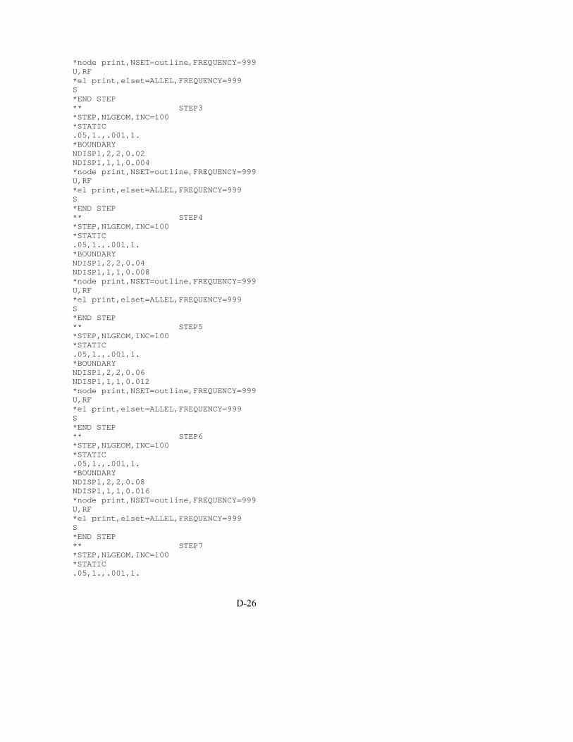
D-26
*node print,NSET=outline,FREQUENCY=999 U,RF *el print,elset=ALLEL,FREQUENCY=999 S *END STEP ** STEP3 *STEP,NLGEOM,INC=100 *STATIC .05,1.,.001,1. *BOUNDARY NDISP1,2,2,0.02 NDISP1,1,1,0.004 *node print,NSET=outline,FREQUENCY=999 U,RF *el print,elset=ALLEL,FREQUENCY=999 S *END STEP ** STEP4 *STEP,NLGEOM,INC=100 *STATIC .05,1.,.001,1. *BOUNDARY NDISP1,2,2,0.04 NDISP1,1,1,0.008 *node print,NSET=outline,FREQUENCY=999 U,RF *el print,elset=ALLEL,FREQUENCY=999 S *END STEP ** STEP5 *STEP,NLGEOM,INC=100 *STATIC .05,1.,.001,1. *BOUNDARY NDISP1,2,2,0.06 NDISP1,1,1,0.012 *node print,NSET=outline,FREQUENCY=999 U,RF *el print,elset=ALLEL,FREQUENCY=999 S *END STEP ** STEP6 *STEP,NLGEOM,INC=100 *STATIC .05,1.,.001,1. *BOUNDARY NDISP1,2,2,0.08 NDISP1,1,1,0.016 *node print,NSET=outline,FREQUENCY=999 U,RF *el print,elset=ALLEL,FREQUENCY=999 S *END STEP ** STEP7 *STEP,NLGEOM,INC=100 *STATIC .05,1.,.001,1.

D-27
*BOUNDARY NDISP1,2,2,0.1 NDISP1,1,1,0.02 *node print,NSET=outline,FREQUENCY=999 U,RF *el print,elset=ALLEL,FREQUENCY=999 S *END STEP
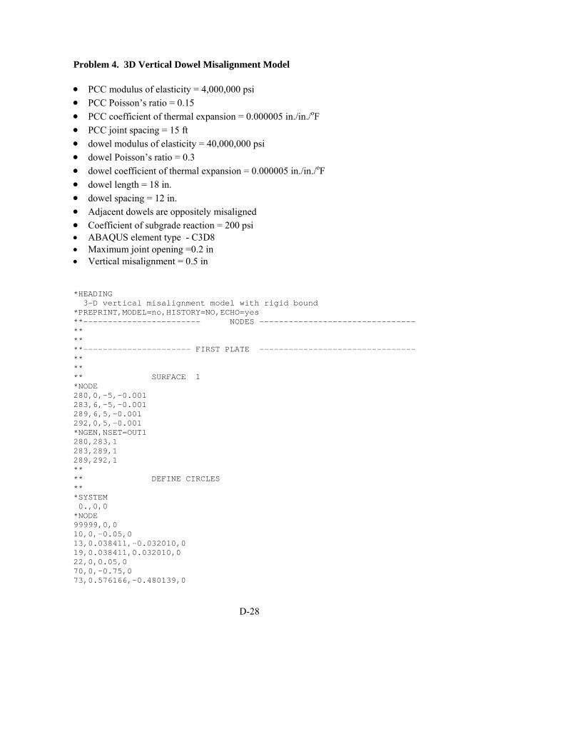
D-28
Problem 4. 3D Vertical Dowel Misalignment Model • PCC modulus of elasticity = 4,000,000 psi • PCC Poisson’s ratio = 0.15 • PCC coefficient of thermal expansion = 0.000005 in./in./oF • PCC joint spacing = 15 ft • dowel modulus of elasticity = 40,000,000 psi • dowel Poisson’s ratio = 0.3 • dowel coefficient of thermal expansion = 0.000005 in./in./oF • dowel length = 18 in. • dowel spacing = 12 in. • Adjacent dowels are oppositely misaligned • Coefficient of subgrade reaction = 200 psi • ABAQUS element type - C3D8 • Maximum joint opening =0.2 in • Vertical misalignment = 0.5 in *HEADING 3-D vertical misalignment model with rigid bound *PREPRINT,MODEL=no,HISTORY=NO,ECHO=yes **------------------------ NODES --------------------------------** ** **---------------------- FIRST PLATE --------------------------------** ** ** SURFACE 1 *NODE 280,0,-5,-0.001 283,6,-5,-0.001 289,6,5,-0.001 292,0,5,-0.001 *NGEN,NSET=OUT1 280,283,1 283,289,1 289,292,1 ** ** DEFINE CIRCLES ** *SYSTEM 0.,0,0 *NODE 99999,0,0 10,0,-0.05,0 13,0.038411,-0.032010,0 19,0.038411,0.032010,0 22,0,0.05,0 70,0,-0.75,0 73,0.576166,-0.480139,0

D-29
79,0.576166,0.480139,0 82,0,0.75,0 100,0,-0.75,0 103,0.576166,-0.480139,0 109,0.576166,0.480139,0 112,0,0.75,0 160,0,-1.1,0 163,0.845043,-0.704202,0 169,0.845043,0.704202,0 172,0,1.1,0 ** CIRCLE 11 *NGEN,LINE=C,NSET=CIRCLE11 10,13,1,99999 13,19,1,99999 19,22,1,99999 ** CIRCLE 12 *NGEN,LINE=C,NSET=CIRCLE12 70,73,1,99999 73,79,1,99999 79,82,1,99999 ** CIRCLE 13 *NGEN,LINE=C,NSET=CIRCLE13 100,103,1,99999 103,109,1,99999 109,112,1,99999 ** CIRCLE 14 *NGEN,NSET=CIRCLE14 160,163,1,99999 163,169,1,99999 169,172,1,99999 *SYSTEM 0,0,0 ** SECTOR 11 *NFILL,NSET=S11 CIRCLE11,CIRCLE12,2,30 ** SECTOR 12 *NFIL,NSET=S12 CIRCLE13,CIRCLE14,3,20 ** SECTOR 13 *NFILL, NSET=S13,BIAS=0.8 CIRCLE14,OUT1,6,20 *NSET,NSET=BS13,generate 180,192,1 200,212,1 220,232,1 240,252,1 260,272,1 280,292,1 *NSET, NSET=SURF1 S11 S12 BS13 ** SURFACE 2 *NODE 18280,0,-5,-9 18283,6,-5,-9 18289,6,5,-9

D-30
18292,0,5,-9 *NGEN,NSET=OUT2 18280,18283,1, 18283,18289,1, 18289,18292,1 ** ** DEFINE CIRCLES ** *SYSTEM 0.,.5,-9. *NODE 88888,0,0 18010,0,-0.05,0 18013,0.038411,-0.032010,0 18019,0.038411, 0.032010,0 18022,0,0.05,0 18070,0,-0.75,0 18073,0.576166,-0.480139,0 18079,0.576166,0.480139,0 18082,0,0.75,0 18100,0,-0.75,0 18103,0.576166,-0.480139,0 18109,0.576166,0.480139,0 18112,0,0.75,0 18160,0,-1.1,0 18163,0.845043,-0.704202,0 18169,0.845043,0.704202,0 18172,0,1.1,0 ** CIRCLE 21 *NGEN,LINE=C,NSET=CIRCLE21 18010,18013,1,88888 18013,18019,1,88888 18019,18022,1,88888 ** CIRCLE 22 *NGEN,LINE=C,NSET=CIRCLE22 18070,18073,1,88888 18073,18079,1,88888 18079,18082,1,88888 ** CIRCLE 23 *NGEN,LINE=C,NSET=CIRCLE23 18100,18103,1,88888 18103,18109,1,88888 18109,18112,1,88888 ** CIRCLE 24 *NGEN,NSET=CIRCLE24 18160,18163,1,88888 18163,18169,1,88888 18169,18172,1,88888 *SYSTEM 0,0,0 ** SECTOR 21 *NFILL,NSET=S21 CIRCLE21,CIRCLE22,2,30 ** SECTOR 22 *NFILL,NSET=S22 CIRCLE23,CIRCLE24,3,20 ** SECTOR 23

D-31
*NFILL,NSET=S23,BIAS=0.8 CIRCLE24,OUT2,6,20 *NSET,NSET=BS23,generate 18160,18172,1 18180,18192,1 18200,18212,1 18220,18232,1 18240,18252,1 18260,18272,1 18280,18292,1 *NSET, NSET=SURF2 S21 S22 BS23 ***------------------- NODES SET OF RIGHT PART *NFILL,NSET=RIGHTND SURF1,SURF2,18,1000 ** ** SURFACE 3 *NODE 36280,0,-5,-18 36283,6,-5,-18 36289,6,5,-18 36292,0,5,-18 *NGEN,NSET=OUT3 36280,36283,1, 36283,36289,1, 36289,36292,1 ** ** DEFINE CIRCLES ** *SYSTEM 0.,0.,-18. *NODE 77777,0,0 36010,0,-0.05,0 36013,0.038411,-0.032010,0 36019,0.038411, 0.032010,0 36022,0,0.05,0 36070,0,-0.75,0 36073,0.576166,-0.480139,0 36079,0.576166,0.480139,0 36082,0,0.75,0 36100,0,-0.75,0 36103,0.576166,-0.480139,0 36109,0.576166,0.480139,0 36112,0,0.75,0 36160,0,-1.1,0 36163,0.845043,-0.704202,0 36169,0.845043,0.704202,0 36172,0,1.1,0 ** CIRCLE 31 *NGEN,LINE=C,NSET=CIRCLE31 36010,36013,1,77777 36013,36019,1,77777 36019,36022,1,77777 ** CIRCLE 32

D-32
*NGEN,LINE=C,NSET=CIRCLE32 36070,36073,1,77777 36073,36079,1,77777 36079,36082,1,77777 ** CIRCLE 33 *NGEN,LINE=C,NSET=CIRCLE33 36100,36103,1,77777 36103,36109,1,77777 36109,36112,1,77777 ** CIRCLE 34 *NGEN,NSET=CIRCLE34 36160,36163,1,77777 36163,36169,1,77777 36169,36172,1,77777 *SYSTEM 0,0,0 ** SECTOR 31 *NFILL,NSET=S31 CIRCLE31,CIRCLE32,2,30 ** SECTOR 32 *NFILL,NSET=S32 CIRCLE33,CIRCLE34,3,20 ** SECTOR 33 *NFILL,NSET=S33,BIAS=0.8 CIRCLE34,OUT3,6,20 *NSET,NSET=BS33,generate 36160,36172,1 36180,36192,1 36200,36212,1 36220,36232,1 36240,36252,1 36260,36272,1 36280,36292,1 *NSET, NSET=SURF3 S31 S32 BS33 ***------------------- NODES SET OF RIGHT AND MIDDLE PARTS *NFILL,NSET=RIMIND SURF2,SURF3,18,1000 ** ***------------------- NODES SET OF LEFT PART ** ** SURFACE 4 *NODE 180280,0,-5,-90 180283,6,-5,-90 180289,6,5,-90 180292,0,5,-90 *NGEN,NSET=OUT4 180280,180283,1, 180283,180289,1, 180289,180292,1 ** ** DEFINE CIRCLES ** *SYSTEM

D-33
0.,0.,-90. *NODE 66666,0,0 180010,0,-0.05,0 180013,0.038411,-0.032010,0 180019,0.038411, 0.032010,0 180022,0,0.05,0 180070,0,-0.75,0 180073,0.576166,-0.480139,0 180079,0.576166,0.480139,0 180082,0,0.75,0 180100,0,-0.75,0 180103,0.576166,-0.480139,0 180109,0.576166,0.480139,0 180112,0,0.75,0 180160,0,-1.1,0 180163,0.845043,-0.704202,0 180169,0.845043,0.704202,0 180172,0,1.1,0 ** CIRCLE 41 *NGEN,LINE=C,NSET=CIRCLE41 180010,180013,1,66666 180013,180019,1,66666 180019,180022,1,66666 ** CIRCLE 42 *NGEN,LINE=C,NSET=CIRCLE42 180070,180073,1,66666 180073,180079,1,66666 180079,180082,1,66666 ** CIRCLE 43 *NGEN,LINE=C,NSET=CIRCLE43 180100,180103,1,66666 180103,180109,1,66666 180109,180112,1,66666 ** CIRCLE 44 *NGEN,NSET=CIRCLE44 180160,180163,1,66666 180163,180169,1,66666 180169,180172,1,66666 *SYSTEM 0,0,0 ** SECTOR 41 *NFILL,NSET=S41 CIRCLE41,CIRCLE42,2,30 ** SECTOR 42 *NFILL,NSET=S42 CIRCLE43,CIRCLE44,3,20 ** SECTOR 43 *NFILL,NSET=S43,BIAS=0.8 CIRCLE44,OUT4,6,20 *NSET,NSET=BS43,generate 180160,180172,1 180180,180192,1 180200,180212,1 180220,180232,1 180240,180252,1 180260,180272,1

D-34
180280,180292,1 *NSET, NSET=SURF4 S41 S42 BS43 ***------------------- NODES SET OF RIGHT MIDDLE AND LEFT PARTS *NFILL,NSET=ALLND SURF3,SURF4,144,1000 ** **----------------- END OF FIRST PLATES NODES SET GENERATION ----------------------- ** ** **------------------------ SECOND PLATE -------------------------------------------** ** ** SURFACE 11 *NODE 1000280,0,-5,0.001 1000283,6,-5,0.001 1000289,6,5,0.001 1000292,0,5,0.001 *NGEN,NSET=OUT11 1000280,1000283,1 1000283,1000289,1 1000289,1000292,1 ** ** DEFINE CIRCLES ** *SYSTEM 0.,0,0.001 *NODE 199999,0,0 1000010,0,-0.05,0 1000013,0.038411,-0.032010,0 1000019,0.038411,0.032010,0 1000022,0,0.05,0 1000070,0,-0.75,0 1000073,0.576166,-0.480139,0 1000079,0.576166,0.480139,0 1000082,0,0.75,0 1000100,0,-0.75,0 1000103,0.576166,-0.480139,0 1000109,0.576166,0.480139,0 1000112,0,0.75,0 1000160,0,-1.1,0 1000163,0.845043,-0.704202,0 1000169,0.845043,0.704202,0 1000172,0,1.1,0 ** CIRCLE 111 *NGEN,LINE=C,NSET=CIRCL111 1000010,1000013,1,199999 1000013,1000019,1,199999 1000019,1000022,1,199999 ** CIRCLE 112 *NGEN,LINE=C,NSET=CIRCL112 1000070,1000073,1,199999 1000073,1000079,1,199999

D-35
1000079,1000082,1,199999 ** CIRCLE 113 *NGEN,LINE=C,NSET=CIRCL113 1000100,1000103,1,199999 1000103,1000109,1,199999 1000109,1000112,1,199999 ** CIRCLE 114 *NGEN,NSET=CIRCL114 1000160,1000163,1,199999 1000163,1000169,1,199999 1000169,1000172,1,199999 *SYSTEM 0,0,0 ** SECTOR 111 *NFILL,NSET=S111 CIRCL111,CIRCL112,2,30 ** SECTOR 112 *NFIL,NSET=S112 CIRCL113,CIRCL114,3,20 ** SECTOR 113 *NFILL, NSET=S113,BIAS=0.8 CIRCL114,OUT11,6,20 *NSET,NSET=BS113,generate 1000180,1000192,1 1000200,1000212,1 1000220,1000232,1 1000240,1000252,1 1000260,1000272,1 1000280,1000292,1 *NSET, NSET=SUR11 S111 S112 BS113 ** SURFACE 12 *NODE 1018280,0,-5,9 1018283,6,-5,9 1018289,6,5,9 1018292,0,5,9 *NGEN,NSET=OUT12 1018280,1018283,1, 1018283,1018289,1, 1018289,1018292,1 ** ** DEFINE CIRCLES ** *SYSTEM 0.,-.5,9. *NODE 188888,0,0 1018010,0,-0.05,0 1018013,0.038411,-0.032010,0 1018019,0.038411, 0.032010,0 1018022,0,0.05,0 1018070,0,-0.75,0 1018073,0.576166,-0.480139,0 1018079,0.576166,0.480139,0

D-36
1018082,0,0.75,0 1018100,0,-0.75,0 1018103,0.576166,-0.480139,0 1018109,0.576166,0.480139,0 1018112,0,0.75,0 1018160,0,-1.1,0 1018163,0.845043,-0.704202,0 1018169,0.845043,0.704202,0 1018172,0,1.1,0 ** CIRCLE 121 *NGEN,LINE=C,NSET=CIRCL121 1018010,1018013,1,188888 1018013,1018019,1,188888 1018019,1018022,1,188888 ** CIRCLE 122 *NGEN,LINE=C,NSET=CIRCL122 1018070,1018073,1,188888 1018073,1018079,1,188888 1018079,1018082,1,188888 ** CIRCLE 123 *NGEN,LINE=C,NSET=CIRCL123 1018100,1018103,1,188888 1018103,1018109,1,188888 1018109,1018112,1,188888 ** CIRCLE 124 *NGEN,NSET=CIRCL124 1018160,1018163,1,188888 1018163,1018169,1,188888 1018169,1018172,1,188888 *SYSTEM 0,0,0 ** SECTOR 121 *NFILL,NSET=S121 CIRCL121,CIRCL122,2,30 ** SECTOR 122 *NFILL,NSET=S122 CIRCL123,CIRCL124,3,20 ** SECTOR 123 *NFILL,NSET=S123,BIAS=0.8 CIRCL124,OUT12,6,20 *NSET,NSET=BS123,generate 1018160,1018172,1 1018180,1018192,1 1018200,1018212,1 1018220,1018232,1 1018240,1018252,1 1018260,1018272,1 1018280,1018292,1 *NSET, NSET=SUR12 S121 S122 BS123 ***------------------- NODES SET OF RIGHT PART *NFILL,NSET=RIGHTND2 SUR11,SUR12,18,1000 ** ** SURFACE 13

D-37
*NODE 1036280,0,-5,18 1036283,6,-5,18 1036289,6,5,18 1036292,0,5,18 *NGEN,NSET=OUT13 1036280,1036283,1, 1036283,1036289,1, 1036289,1036292,1 ** ** DEFINE CIRCLES ** *SYSTEM 0.,0.,18. *NODE 177777,0,0 1036010,0,-0.05,0 1036013,0.038411,-0.032010,0 1036019,0.038411, 0.032010,0 1036022,0,0.05,0 1036070,0,-0.75,0 1036073,0.576166,-0.480139,0 1036079,0.576166,0.480139,0 1036082,0,0.75,0 1036100,0,-0.75,0 1036103,0.576166,-0.480139,0 1036109,0.576166,0.480139,0 1036112,0,0.75,0 1036160,0,-1.1,0 1036163,0.845043,-0.704202,0 1036169,0.845043,0.704202,0 1036172,0,1.1,0 ** CIRCLE 131 *NGEN,LINE=C,NSET=CIRCL131 1036010,1036013,1,177777 1036013,1036019,1,177777 1036019,1036022,1,177777 ** CIRCLE 132 *NGEN,LINE=C,NSET=CIRCL132 1036070,1036073,1,177777 1036073,1036079,1,177777 1036079,1036082,1,177777 ** CIRCLE 133 *NGEN,LINE=C,NSET=CIRCL133 1036100,1036103,1,177777 1036103,1036109,1,177777 1036109,1036112,1,177777 ** CIRCLE 134 *NGEN,NSET=CIRCL134 1036160,1036163,1,177777 1036163,1036169,1,177777 1036169,1036172,1,177777 *SYSTEM 0,0,0 ** SECTOR 131 *NFILL,NSET=S131 CIRCL131,CIRCL132,2,30

D-38
** SECTOR 132 *NFILL,NSET=S132 CIRCL133,CIRCL134,3,20 ** SECTOR 133 *NFILL,NSET=S133,BIAS=0.8 CIRCL134,OUT13,6,20 *NSET,NSET=BS133,generate 1036160,1036172,1 1036180,1036192,1 1036200,1036212,1 1036220,1036232,1 1036240,1036252,1 1036260,1036272,1 1036280,1036292,1 *NSET, NSET=SUR13 S131 S132 BS133 ***------------------- NODES SET OF RIGHT AND MIDDLE PARTS *NFILL,NSET=RIMIND2 SUR12,SUR13,18,1000 ** ***------------------- NODES SET OF LEFT PART ** ** SURFACE 14 *NODE 1180280,0,-5,90 1180283,6,-5,90 1180289,6,5,90 1180292,0,5,90 *NGEN,NSET=OUT14 1180280,1180283,1, 1180283,1180289,1, 1180289,1180292,1 ** ** DEFINE CIRCLES ** *SYSTEM 0.,0.,90. *NODE 166666,0,0 1180010,0,-0.05,0 1180013,0.038411,-0.032010,0 1180019,0.038411, 0.032010,0 1180022,0,0.05,0 1180070,0,-0.75,0 1180073,0.576166,-0.480139,0 1180079,0.576166,0.480139,0 1180082,0,0.75,0 1180100,0,-0.75,0 1180103,0.576166,-0.480139,0 1180109,0.576166,0.480139,0 1180112,0,0.75,0 1180160,0,-1.1,0 1180163,0.845043,-0.704202,0 1180169,0.845043,0.704202,0 1180172,0,1.1,0

D-39
** CIRCLE 141 *NGEN,LINE=C,NSET=CIRCL141 1180010,1180013,1,166666 1180013,1180019,1,166666 1180019,1180022,1,166666 ** CIRCLE 142 *NGEN,LINE=C,NSET=CIRCL142 1180070,1180073,1,166666 1180073,1180079,1,166666 1180079,1180082,1,166666 ** CIRCLE 143 *NGEN,LINE=C,NSET=CIRCL143 1180100,1180103,1,166666 1180103,1180109,1,166666 1180109,1180112,1,166666 ** CIRCLE 144 *NGEN,NSET=CIRCL144 1180160,1180163,1,166666 1180163,1180169,1,166666 1180169,1180172,1,166666 *SYSTEM 0,0,0 ** SECTOR 141 *NFILL,NSET=S141 CIRCL141,CIRCL142,2,30 ** SECTOR 142 *NFILL,NSET=S142 CIRCL143,CIRCL144,3,20 ** SECTOR 143 *NFILL,NSET=S143,BIAS=0.8 CIRCL144,OUT14,6,20 *NSET,NSET=BS143,generate 1180160,1180172,1 1180180,1180192,1 1180200,1180212,1 1180220,1180232,1 1180240,1180252,1 1180260,1180272,1 1180280,1180292,1 *NSET, NSET=SUR14 S141 S142 BS143 ***------------------- NODES SET OF RIGHT MIDDLE AND LEFT PARTS *NFILL,NSET=ALLND2 SUR13,SUR14,144,1000 ** **----------------- END OF SECOND PLATE NODES SET GENERATION ----------------------- ** ** **-------------------- SYMMETRY SURFACE NODES -------------------------** ** *NSET,NSET=NSYMM,generate 10,28010,1000 40,28040,1000 70,28070,1000

D-40
100,28100,1000 120,28120,1000 140,28140,1000 160,28160,1000 180,28180,1000 200,28200,1000 220,28220,1000 240,28240,1000 260,28260,1000 22,28022,1000 52,28052,1000 82,28082,1000 112,28112,1000 132,28132,1000 152,28152,1000 172,28172,1000 192,28192,1000 212,28212,1000 232,28232,1000 252,28252,1000 272,28272,1000 280,28280,1000 292,28292,1000 36010,180010,8000 36040,180040,8000 36070,180070,8000 36100,180100,8000 36120,180120,8000 36140,180140,8000 36160,180160,8000 36180,180180,8000 36200,180200,8000 36220,180220,8000 36240,180240,8000 36260,180260,8000 36022,180022,8000 36052,180052,8000 36082,180082,8000 36112,180112,8000 36132,180132,8000 36152,180152,8000 36172,180172,8000 36192,180192,8000 36212,180212,8000 36232,180232,8000 36252,180252,8000 36272,180272,8000 36280,180280,8000 36292,180292,8000 1000010,1028010,1000 1000040,1028040,1000 1000070,1028070,1000 1000100,1028100,1000 1000120,1028120,1000 1000140,1028140,1000 1000160,1028160,1000 1000180,1028180,1000

D-41
1000200,1028200,1000 1000220,1028220,1000 1000240,1028240,1000 1000260,1028260,1000 1000022,1028022,1000 1000052,1028052,1000 1000082,1028082,1000 1000112,1028112,1000 1000132,1028132,1000 1000152,1028152,1000 1000172,1028172,1000 1000192,1028192,1000 1000212,1028212,1000 1000232,1028232,1000 1000252,1028252,1000 1000272,1028272,1000 1000280,1028280,1000 1000292,1028292,1000 1036010,1180010,8000 1036040,1180040,8000 1036070,1180070,8000 1036100,1180100,8000 1036120,1180120,8000 1036140,1180140,8000 1036160,1180160,8000 1036180,1180180,8000 1036200,1180200,8000 1036220,1180220,8000 1036240,1180240,8000 1036260,1180260,8000 1036022,1180022,8000 1036052,1180052,8000 1036082,1180082,8000 1036112,1180112,8000 1036132,1180132,8000 1036152,1180152,8000 1036172,1180172,8000 1036192,1180192,8000 1036212,1180212,8000 1036232,1180232,8000 1036252,1180252,8000 1036272,1180272,8000 1036280,1180280,8000 1036292,1180292,8000 ** ** ** **-------------------------- DOWEL NODES ---------------------------------------** ** *NSET,NSET=NSTEEL,generate 10,22 40,52 70,82 1010,1022 1040,1052 1070,1082

D-42
2010,2022 2040,2052 2070,2082 3010,3022 3040,3052 3070,3082 4010,4022 4040,4052 4070,4082 5010,5022 5040,5052 5070,5082 6010,6022 6040,6052 6070,6082 7010,7022 7040,7052 7070,7082 8010,8022 8040,8052 8070,8082 9010,9022 9040,9052 9070,9082 10010,10022 10040,10052 10070,10082 11010,11022 11040,11052 11070,11082 12010,12022 12040,12052 12070,12082 13010,13022 13040,13052 13070,13082 14010,14022 14040,14052 14070,14082 15010,15022 15040,15052 15070,15082 16010,16022 16040,16052 16070,16082 17010,17022 17040,17052 17070,17082 18010,18022 18040,18052 18070,18082 1000010,1000022 1000040,1000052 1000070,1000082 1001010,1001022 1001040,1001052 1001070,1001082

D-43
1002010,1002022 1002040,1002052 1002070,1002082 1003010,1003022 1003040,1003052 1003070,1003082 1004010,1004022 1004040,1004052 1004070,1004082 1005010,1005022 1005040,1005052 1005070,1005082 1006010,1006022 1006040,1006052 1006070,1006082 1007010,1007022 1007040,1007052 1007070,1007082 1008010,1008022 1008040,1008052 1008070,1008082 1009010,1009022 1009040,1009052 1009070,1009082 1010010,1010022 1010040,1010052 1010070,1010082 1011010,1011022 1011040,1011052 1011070,1011082 1012010,1012022 1012040,1012052 1012070,1012082 1013010,1013022 1013040,1013052 1013070,1013082 1014010,1014022 1014040,1014052 1014070,1014082 1015010,1015022 1015040,1015052 1015070,1015082 1016010,1016022 1016040,1016052 1016070,1016082 1017010,1017022 1017040,1017052 1017070,1017082 1018010,1018022 1018040,1018052 1018070,1018082 ** *NSET,NSET=NBOU,generate 283,180283,1000 284,180284,1000 285,180285,1000 286,180286,1000
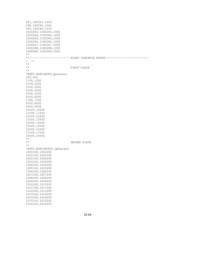
D-44
287,180287,1000 288,180288,1000 289,180289,1000 1000283,1180283,1000 1000284,1180284,1000 1000285,1180285,1000 1000286,1180286,1000 1000287,1180287,1000 1000288,1180288,1000 1000289,1180289,1000 ** **----------------------- RIGHT CONCRETE NODES-------------------------- ** ** ** FIRST PLATE ** *NSET,NSET=NCRT,generate 100,292 1100,1292 2100,2292 3100,3292 4100,4292 5100,5292 6100,6292 7100,7292 8100,8292 9100,9292 10100,10292 11100,11292 12100,12292 13100,13292 14100,14292 15100,15292 16100,16292 17100,17292 18100,18292 ** ** SECOND PLATE ** *NSET,NSET=NCRT2,generate 1000100,1000292 1001100,1001292 1002100,1002292 1003100,1003292 1004100,1004292 1005100,1005292 1006100,1006292 1007100,1007292 1008100,1008292 1009100,1009292 1010100,1010292 1011100,1011292 1012100,1012292 1013100,1013292 1014100,1014292 1015100,1015292 1016100,1016292

D-45
1017100,1017292 1018100,1018292 ** **---------------------- MIDDLE AND LEFT CONCRETE NODES-------------------------- ** ** ** FIRST PLATE ** *NSET,NSET=NMID,generate 19010,180292 ** ** ** SECOND PLATE ** *NSET,NSET=NMID2,generate 1019010,1180292 ** **---------------------- ALL CONCRETE NODES-------------------------- ** ** *NSET,NSET=NCONCR NCRT NMID NCRT2 NMID2 ** ** ** **-------------------- OUTPUT NODES -------------------------** ** *NSET,NSET=NFO,generate 280,180280,2000 1000280,1180280,2000 *NSET,NSET=outline SURF4 160,172 ** **------------------------- ELEMENTS -------------------------------------- ** ** **---------------------------- FIRST PLATE ----------------------------------------** ** **------------------------ STEEL --------------------------------------- ** ** ** INSIDE *ELEMENT,TYPE=C3D8,ELSET=STIN 10,1010,1040,1041,1011,10,40,41,11 *ELGEN,ELSET=STIN 10,1,20,1,12,1,3,18,1000,1000 ** OUTSIDE *ELEMENT,TYPE=C3D8,ELSET=STOU 12,1040,1070,1071,1041,40,70,71,41 *ELGEN,ELSET=STOU 12,12,1,3,1,1,1,18,1000,1000
D-46
** **------------------------ CONCRETE --------------------------------------** ** ** RIGHT PART ** ** INSIDE ** *ELEMENT,TYPE=C3D8,ELSET=COINR 50,1100,1120,1121,1101,100,120,121,101 18050,19040,19120,19121,19041,18100,18120,18121,18101 *ELGEN,ELSET=COINR 50,12,1,9,1,1,1,18,1000,1000 ** ** OUTSIDE ** *ELEMENT,TYPE=C3D8,ELSET=COOUR 51,1120,1160,1161,1121,120,160,161,121 18051,19120,19160,19161,19121,18120,18160,18161,18121 *ELGEN,ELSET=COOUR 51,4,40,1,12,1,9,18,1000,1000 18051,4,40,1,12,1,9 ** ** ** MIDDLE PART ** ** INSIDE ** *ELEMENT,TYPE=C3D8,ELSET=COINM 19010,20010,20040,20041,20011,19010,19040,19041,19011 *ELGEN,ELSET=COINM 19010,1,40,1,12,1,3,9,1000,1000 ** ** OUTSIDE *ELEMENT,TYPE=C3D8,ELSET=COOUM 19050,20040,20120,20121,20041,19040,19120,19121,19041 19051,20120,20160,20161,20121,19120,19160,19161,19121 *ELGEN,ELSET=COOUM 19050,12,1,9,1,1,1,9,1000,1000 19051,4,40,1,12,1,9,9,1000,1000 ** ** ** LEFT PART ** ** INSIDE ** *ELEMENT,TYPE=C3D8,ELSET=COINL 28010,36010,36040,36041,36011,28010,28040,28041,28011 *ELGEN,ELSET=COINL 28010,1,40,1,12,1,3,19,8000,8000 ** ** OUTSIDE *ELEMENT,TYPE=C3D8,ELSET=COOUL 28050,36040,36120,36121,36041,28040,28120,28121,28041 28051,36120,36160,36161,36121,28120,28160,28161,28121 *ELGEN,ELSET=COOUL 28050,12,1,9,1,1,1,19,8000,8000

D-47
28051,4,40,1,12,1,9,19,8000,8000 ** **----------------- END OF FIRST PLATE ELEMENT SET GENERATION ----------------------- ** ** ** **--------------------------- SECOND PLATE ------------------------------------- ** ** *elcopy,old set=STIN, new set=STIN2, element shift=1000000, shift nodes=1000000, reflect *elcopy,old set=STOU, new set=STOU2, element shift=1000000, shift nodes=1000000, reflect *elcopy,old set=COINR,new set=COINR2,element shift=1000000, shift nodes=1000000, reflect *elcopy,old set=COOUR,new set=COOUR2,element shift=1000000, shift nodes=1000000, reflect *elcopy,old set=COINM,new set=COINM2,element shift=1000000, shift nodes=1000000, reflect *elcopy,old set=COOUM,new set=COOUM2,element shift=1000000, shift nodes=1000000, reflect *elcopy,old set=COINL,new set=COINL2,element shift=1000000, shift nodes=1000000, reflect *elcopy,old set=COOUL,new set=COOUL2,element shift=1000000, shift nodes=1000000, reflect ** **----------------- END OF SECOND PLATE ELEMENT SET GENERATION ----------------------- ** ** **--------------------------- INTERIM PART ---------------------------------------------** ** ** ** INSIDE *ELEMENT,TYPE=C3D8,ELSET=STINI 2000010,10,40,41,11,1000010,1000040,1000041,1000011 *ELGEN,ELSET=STINI 2000010,1,20,1,12,1,3 ** OUTSIDE *ELEMENT,TYPE=C3D8,ELSET=STOUI 2000012,40,70,71,41,1000040,1000070,1000071,1000041 *ELGEN,ELSET=STOUI 2000012,12,1,3,1,1,1 ** **----------------- END OF INTERIM PART ELEMENT SET GENERATION ----------------------- ** *ELEMENT,TYPE=SPRING1,ELSET=s1 1,16 *SPRING,ELSET=s1 1 1 *ELEMENT,TYPE=SPRING1,ELSET=s2 2,10 3,22 *SPRING,ELSET=s2 3 1

D-48
*ELEMENT,TYPE=SPRING1,ELSET=s22 1000002,1000010 1000003,1000022 *SPRING,ELSET=s22 2 1 ** ** **------------------------- MATERIAL DATA ** **----------------------- STEEL *MATERIAL,NAME=dowel *ELASTIC 4.E7,0.3 *EXPANSION 5.E-6 ** **----------------------- CONCRETE ** ** RIGHT PART ** *MATERIAL,NAME=concr1 *ELASTIC 4.E6,0.15 *EXPANSION 5.E-6 ** ** ** ** MIDDLE and LEFT PARTS ** *MATERIAL,NAME=concr2 *ELASTIC 4.E6,0.15,-100. 4.E3,0.15,0. 4.E6,0.15,0.01 *EXPANSION 5.E-6 ** ** ** **------------------------ PROPERTY DEFINITION ** **----------------------- STEEL ** *SOLID SECTION,MATERIAL=dowel,ELSET=STIN *SOLID SECTION,MATERIAL=dowel,ELSET=STOU *SOLID SECTION,MATERIAL=dowel,ELSET=STIN2 *SOLID SECTION,MATERIAL=dowel,ELSET=STOU2 *SOLID SECTION,MATERIAL=dowel,ELSET=STINI *SOLID SECTION,MATERIAL=dowel,ELSET=STOUI ** **----------------------- CONCRETE ** ** RIGHT PART ** *SOLID SECTION,MATERIAL=concr1,ELSET=COINR

D-49
*SOLID SECTION,MATERIAL=concr1,ELSET=COOUR *SOLID SECTION,MATERIAL=concr1,ELSET=COINR2 *SOLID SECTION,MATERIAL=concr1,ELSET=COOUR2 ** ** MIDDLE PART ** *SOLID SECTION,MATERIAL=concr2,ELSET=COINM *SOLID SECTION,MATERIAL=concr2,ELSET=COOUM *SOLID SECTION,MATERIAL=concr2,ELSET=COINM2 *SOLID SECTION,MATERIAL=concr2,ELSET=COOUM2 ** ** LEFT PART ** *SOLID SECTION,MATERIAL=concr2,ELSET=COINL *SOLID SECTION,MATERIAL=concr2,ELSET=COOUL *SOLID SECTION,MATERIAL=concr2,ELSET=COINL2 *SOLID SECTION,MATERIAL=concr2,ELSET=COOUL2 ** ** **------------------------ SURFACE DEFENION ** *SURFACE DEFINITION, NAME=CONCR COINR, S6 *SURFACE DEFINITION, NAME=STEEL STOU, S4 ** *SURFACE DEFINITION, NAME=CONCR2 COINR2, S3 *SURFACE DEFINITION, NAME=STEEL2 STOU2, S5 ** **-----------------------CONTACT PROPERTIES ** *CONTACT PAIR, INTERACTION=FRIC2 CONCR, STEEL ** *SURFACE INTERACTION, NAME=FRIC2 ** *FRICTION, TAUMAX=0,SLIP TOLERANCE=0.1 .5 *SURFACE BEHAVIOR, NO SEPARATION ** *CONTACT PAIR, INTERACTION=FRIC22 CONCR2, STEEL2 ** *SURFACE INTERACTION, NAME=FRIC22 ** *FRICTION, TAUMAX=0,SLIP TOLERANCE=0.1 .5 *SURFACE BEHAVIOR, NO SEPARATION ** ** **------------------------- FOUNDATION ---------------------------------** ** *ELSET,ELSET=ELFO,generate 54,28054,1000

D-50
63,28063,1000 72,28072,1000 36054,172054,8000 36063,172063,8000 36072,172072,8000 *FOUNDATION ELFO,F4,200 ** *ELSET,ELSET=ELFO2,generate 1000054,1028054,1000 1000063,1028063,1000 1000072,1028072,1000 1036054,1172054,8000 1036063,1172063,8000 1036072,1172072,8000 *FOUNDATION ELFO2,F5,200 ** **------------------------ OUTPUT ELEMENTS ---------------------------------** ** *ELSET,ELSET=CONTACT,generate 52,19052,1000 53,19053,1000 54,19054,1000 151,19151,1000 152,19152,1000 153,19153,1000 *RESTART,WRITE,FREQUENCY=999,OVERLAY ** **----------------------- HISTORY DEFENITION -----------------------------** ** ** ...................STEP1 *STEP,NLGEOM,INC=100 *STATIC .05,1,.01,1. ** ...................TEMPERATURE *TEMPERATURE NSTEEL, 15.0 NMID,0. NMID2,0. *BOUNDARY NSYMM,1 SURF4,3 SUR14,3 NBOU,2 *node print,NSET=outline,FREQUENCY=999 U,RF *el print,elset=CONTACT,POSITION=AVERAGED AT NODES,FREQUENCY=999 S *END STEP ** ...................STEP2 *STEP,NLGEOM,INC=100 *STATIC .05,1,.01,1. ** ...................TEMPERATURE

D-51
*TEMPERATURE NSTEEL, 15.0 NMID,0.01 NMID2,0.01 *BOUNDARY NSYMM,1 SURF4,3 SUR14,3 *node print,NSET=outline,FREQUENCY=999 U,RF *el print,elset=CONTACT,POSITION=AVERAGED AT NODES,FREQUENCY=999 S *END STEP ** ...................STEP3 *STEP,NLGEOM,INC=100 *STATIC .05,1,.001,.1 *BOUNDARY SURF4,3,3,-0.02 SUR14,3,3,0.02 *node print,NSET=outline,FREQUENCY=999 U,RF *el print,elset=CONTACT,POSITION=AVERAGED AT NODES,FREQUENCY=999 S *END STEP ** ...................STEP4 *STEP,NLGEOM,INC=100 *STATIC .05,1,.001,.1 *BOUNDARY SURF4,3,3,-0.03 SUR14,3,3,0.03 *node print,NSET=outline,FREQUENCY=999 U,RF *el print,elset=CONTACT,POSITION=AVERAGED AT NODES,FREQUENCY=999 S *END STEP ** ...................STEP5 *STEP,NLGEOM,INC=100 *STATIC .05,1,.001,.1 *BOUNDARY SURF4,3,3,-0.04 SUR14,3,3,0.04 *node print,NSET=outline,FREQUENCY=999 U,RF *el print,elset=CONTACT,POSITION=AVERAGED AT NODES,FREQUENCY=999 S *END STEP ** ...................STEP6 *STEP,NLGEOM,INC=100 *STATIC .05,1,.001,.1 *BOUNDARY SURF4,3,3,-0.05 SUR14,3,3,0.05 *node print,NSET=outline,FREQUENCY=999
D-52
U,RF *el print,elset=CONTACT,POSITION=AVERAGED AT NODES,FREQUENCY=999 S *END STEP ** ...................STEP7 *STEP,NLGEOM,INC=100 *STATIC .05,1,.001,.1 *BOUNDARY SURF4,3,3,-0.06 SUR14,3,3,0.06 *node print,NSET=outline,FREQUENCY=999 U,RF *el print,elset=CONTACT,POSITION=AVERAGED AT NODES,FREQUENCY=999 S *END STEP ** ...................STEP8 *STEP,NLGEOM,INC=100 *STATIC .05,1,.001,.1 *BOUNDARY SURF4,3,3,-0.07 SUR14,3,3,0.07 *node print,NSET=outline,FREQUENCY=999 U,RF *el print,elset=CONTACT,POSITION=AVERAGED AT NODES,FREQUENCY=999 S *END STEP ** ...................STEP9 *STEP,NLGEOM,INC=100 *STATIC .05,1,.001,.1 *BOUNDARY SURF4,3,3,-0.08 SUR14,3,3,0.08 *node print,NSET=outline,FREQUENCY=999 U,RF *el print,elset=CONTACT,POSITION=AVERAGED AT NODES,FREQUENCY=999 S *END STEP ** ...................STEP10 *STEP,NLGEOM,INC=100 *STATIC .05,1,.001,.1 *BOUNDARY SURF4,3,3,-0.09 SUR14,3,3,0.09 *node print,NSET=outline,FREQUENCY=999 U,RF *el print,elset=CONTACT,POSITION=AVERAGED AT NODES,FREQUENCY=999 S *END STEP ** ...................STEP11 *STEP,NLGEOM,INC=100 *STATIC .05,1,.001,.1 *BOUNDARY

D-53
SURF4,3,3,-0.1 SUR14,3,3,0.1 *node print,NSET=outline,FREQUENCY=999 U,RF *el print,elset=CONTACT,POSITION=AVERAGED AT NODES,FREQUENCY=999 S,MISES,PRESS *END STEP

D-54
Problem 5. 2D Horizontal Dowel Misalignment Model • PCC modulus of elasticity = 4,000,000 psi • PCC Poisson’s ratio = 0.15 • PCC coefficient of thermal expansion = 0.000005 in./in./oF • PCC joint spacing = 15 ft • dowel modulus of elasticity = 40,000,000 psi • dowel Poisson’s ratio = 0.3 • dowel coefficient of thermal expansion = 0.000005 in./in./oF • dowel length = 18 in. • dowel spacing = 24 in (doubled to reduce effect of opposite misalignment) • Coefficient of subgrade reaction = 200 psi • ABAQUS element type - CPS4R • Maximum axis displacement =0.1 in. • Horizontals misalignment =1.0 in *HEADING 2-D horizontal misalignment model *PREPRINT,MODEL=no,HISTORY=NO,ECHO=yes ** **------------------ first plate nodes ** ** ................. NODES CONCRETE ** *NODE 1,-0.01,6. 111,-0.01,0.5 131,-0.01,-0.5 241,-0.01,-6. *ngen,nset=line1 1,111,1 *ngen,nset=line2 131,241,1 *NODE 95001,-9.5,6 95111,-9.5,1.5 95131,-9.5,0.5 95241,-9.5,-6 *ngen,nset=line3 95001,95111,1 *ngen,nset=line4 95131,95241,1 *ngen,nset=line11 95111,95131,1 *nfill line1,line3,95,1000 *nfill line2,line4,95,1000 *NODE 140001,-14.,6. 140111,-14.,0.5

D-55
140131,-14.,-0.5 140241,-14.,-6 *ngen,nset=line5 140001,140111,1 *ngen,nset=line6 140131,140241,1 *ngen,nset=line12 140111,140131,1 *nfill line3,line5,45,1000 *nfill line4,line6,45,1000 *nfill line11,line12,45,1000 *NODE 900001,-90.,6. 900111,-90.,0.5 900131,-90.,-0.5 900241,-90.,-6. *ngen,nset=line7 900001,900111,1 *ngen,nset=line8 900131,900241,1 *ngen,nset=line13 900111,900131,1 *nfill line5,line7,760,1000 *nfill line6,line8,760,1000 *nfill line12,line13,760,1000 ** **---------------------- NODES STEEL ** *NODE 501,-0.01,0.5 511,-0.01,-0.5 *ngen,nset=line9 501,511,1 *node 95501,-9.5,1.5 95511,-9.5,0.5 *ngen,nset=line10 95501,95511,1 *nfill line9,line10,95,1000 **** ** ------------------second plate nodes ** ** ................. NODES CONCRETE ** *NODE 1000001,0.01,6. 1000111,0.01,0.5 1000131,0.01,-0.5 1000241,0.01,-6. *ngen,nset=lin1

D-56
1000001,1000111,1 *ngen,nset=lin2 1000131,1000241,1 *NODE 1095001,9.5,6 1095111,9.5,-0.5 1095131,9.5,-1.5 1095241,9.5,-6 *ngen,nset=lin3 1095001,1095111,1 *ngen,nset=lin4 1095131,1095241,1 *ngen,nset=lin11 1095111,1095131,1 *nfill lin1,lin3,95,1000 *nfill lin2,lin4,95,1000 *NODE 1140001,14.,6. 1140111,14.,0.5 1140131,14.,-0.5 1140241,14.,-6 *ngen,nset=lin5 1140001,1140111,1 *ngen,nset=lin6 1140131,1140241,1 *ngen,nset=lin12 1140111,1140131,1 *nfill lin3,lin5,45,1000 *nfill lin4,lin6,45,1000 *nfill lin11,lin12,45,1000 *NODE 1900001,90.,6. 1900111,90.,0.5 1900131,90.,-0.5 1900241,90.,-6. *ngen,nset=lin7 1900001,1900111,1 *ngen,nset=lin8 1900131,1900241,1 *ngen,nset=lin13 1900111,1900131,1 *nfill lin5,lin7,760,1000 *nfill lin6,lin8,760,1000 *nfill lin12,lin13,760,1000 ** **---------------------- NODES STEEL ** *NODE 1000501,0.01,0.5
D-57
1000511,0.01,-0.5 *ngen,nset=lin9 1000501,1000511,1 *node 1095501,9.5,-0.5 1095511,9.5,-1.5 *ngen,nset=lin10 1095501,1095511,1 *nfill lin9,lin10,95,1000 ** **------------- END NODES GENERATION ** *NSET,NSET=NCON4,generate 95001,900241 1095001,1900241 *NSET,NSET=NBOU,generate 1,900001,5000 1000001,1900001,5000 241,900241,5000 1000241,1900241,5000 *NSET,NSET=NLEFT,generate 900001,900241 *NSET,NSET=NRGHT,generate 1900001,1900241 *NSET,NSET=NSTEEL,generate 501,90501,1000 502,90502,1000 503,90503,1000 504,90504,1000 505,90505,1000 506,90506,1000 507,90507,1000 508,90508,1000 509,90509,1000 510,90510,1000 511,90511,1000 1000501,1090501,1000 1000502,1090502,1000 1000503,1090503,1000 1000504,1090504,1000 1000505,1090505,1000 1000506,1090506,1000 1000507,1090507,1000 1000508,1090508,1000 1000509,1090509,1000 1000510,1090510,1000 1000511,1090511,1000 ** ...............ELEMENTS CONCRETE ** *ELEMENT,TYPE=CPS4R,ELSET=CON1 1,5011,11,1,5001 18,5151,151,141,5141 *ELGEN,ELSET=CON1 1,10,10,1,19,5000,5000 18,10,10,1,19,5000,5000 *ELEMENT,TYPE=CPS4R,ELSET=CON2A

D-58
11,5111,111,101,5101 *ELGEN,ELSET=CON2A 11,19,5000,5000 *ELEMENT,TYPE=CPS4R,ELSET=CON2B 17,5141,141,131,5131 *ELGEN,ELSET=CON2B 17,19,5000,5000 *ELEMENT,TYPE=CPS4R,ELSET=CON3 95001,100011,95011,95001,100001 95012,100115,95115,95111,100111 95017,100141,95141,95131,100131 *ELGEN,ELSET=CON3 95001,11,10,1,9,5000,5000 95012,5,4,1,9,5000,5000 95017,11,10,1,9,5000,5000 *ELEMENT,TYPE=CPS4R,ELSET=CON4 140001,180011,140011,140001,180001 140012,180115,140115,140111,180111 140017,180141,140141,140131,180131 *ELGEN,ELSET=CON4 140001,11,10,1,19,40000,40000 140012,5,4,1,19,40000,40000 140017,11,10,1,19,40000,40000 ** **-----------------------ELEMENTS STEEL *ELEMENT,TYPE=CPS4R,ELSET=st1 12,5503,503,501,5501 *ELGEN,ELSET=st1 12,18,5000,5000 *ELEMENT,TYPE=CPS4R,ELSET=st2 13,5505,505,503,5503 *ELGEN,ELSET=st2 13,3,2,1,18,5000,5000 *ELEMENT,TYPE=CPS4R,ELSET=st3 16,5511,511,509,5509 *ELGEN,ELSET=st3 16,18,5000,5000 *ELEMENT,TYPE=CPS4R,ELSET=st0 2000001,503,1000503,1000501,501 *ELGEN,ELSET=st0 2000001,5,2,1 ** *elcopy,old set=CON1,new set=CON51,element shift=1000000,shift nodes=1000000,reflect *elcopy,old set=CON2A,new set=CON52A,element shift=1000000,shift nodes=1000000,reflect *elcopy,old set=CON2B,new set=CON52B,element shift=1000000,shift nodes=1000000,reflect *elcopy,old set=CON3,new set=CON53,element shift=1000000,shift nodes=1000000,reflect *elcopy,old set=CON4,new set=CON54,element shift=1000000,shift nodes=1000000,reflect *elcopy,old set=st1,new set=st51,element shift=1000000,shift nodes=1000000,reflect *elcopy,old set=st2,new set=st52,element shift=1000000,shift nodes=1000000,reflect

D-59
*elcopy,old set=st3,new set=st53,element shift=1000000,shift nodes=1000000,reflect ** ** ---------------- first plate contact pairs ** ** contact pair 1 ** *SURFACE DEFINITION, NAME=CONCR1 CON2A, S1 *SURFACE DEFINITION, NAME=STE1 ST1, S3 *CONTACT PAIR, INTERACTION=FRIC2 CONCR1, STE1 *SURFACE INTERACTION, NAME=FRIC2 2.178 *FRICTION, TAUMAX=0,SLIP TOLERANCE=0.1 .3 *SURFACE BEHAVIOR, NO SEPARATION ** ** contact pair 2 ** *SURFACE DEFINITION, NAME=CONCR2 CON2B, S3 *SURFACE DEFINITION, NAME=STE2 ST3, S1 *CONTACT PAIR, INTERACTION=FRC2 CONCR2, STE2 *SURFACE INTERACTION, NAME=FRC2 2.178 *FRICTION, TAUMAX=0,SLIP TOLERANCE=0.1 .3 *SURFACE BEHAVIOR, NO SEPARATION ** ** ----------------second plate contact pairs ** ** contact pair 1 ** *SURFACE DEFINITION, NAME=CONCR51 CON52A, S4 *SURFACE DEFINITION, NAME=STE51 ST51, S2 *CONTACT PAIR, INTERACTION=FRIC52 CONCR51, STE51 *SURFACE INTERACTION, NAME=FRIC52 2.178 *FRICTION, TAUMAX=0,SLIP TOLERANCE=0.2 .3 *SURFACE BEHAVIOR, NO SEPARATION ** ** contact pair 2 ** *SURFACE DEFINITION, NAME=CONCR52 CON52B, S2 *SURFACE DEFINITION, NAME=STE52 ST53, S4 *CONTACT PAIR, INTERACTION=FRC52 CONCR52, STE52

D-60
*SURFACE INTERACTION, NAME=FRC52 2.178 *FRICTION, TAUMAX=0,SLIP TOLERANCE=0.1 .3 *SURFACE BEHAVIOR, NO SEPARATION ** ** **--------------------------- MATERIALS ** *MATERIAL,NAME=concr1 *ELASTIC 4.E6,0.15 *MATERIAL,NAME=concr2 *ELASTIC 4.E3,0.15,0. 4.E6,0.15,.01 *MATERIAL,NAME=dowel *ELASTIC 4.E7,0.3 *EXPANSION 5.E-6 *SOLID SECTION,MATERIAL=concr1,ELSET=CON1 2.178 *SOLID SECTION,MATERIAL=concr1,ELSET=CON2A 2.178 *SOLID SECTION,MATERIAL=concr1,ELSET=CON2B 2.178 *SOLID SECTION,MATERIAL=concr2,ELSET=CON3 2.178 *SOLID SECTION,MATERIAL=concr2,ELSET=CON4 2.178 *SOLID SECTION,MATERIAL=dowel,ELSET=ST0 2.178 *SOLID SECTION,MATERIAL=dowel,ELSET=ST1 2.178 *SOLID SECTION,MATERIAL=dowel,ELSET=ST2 2.178 *SOLID SECTION,MATERIAL=dowel,ELSET=ST3 2.178 *SOLID SECTION,MATERIAL=concr1,ELSET=CON51 2.178 *SOLID SECTION,MATERIAL=concr1,ELSET=CON52A 2.178 *SOLID SECTION,MATERIAL=concr1,ELSET=CON52B 2.178 *SOLID SECTION,MATERIAL=concr2,ELSET=CON53 2.178 *SOLID SECTION,MATERIAL=concr2,ELSET=CON54 2.178 *SOLID SECTION,MATERIAL=dowel,ELSET=ST51 2.178 *SOLID SECTION,MATERIAL=dowel,ELSET=ST52 2.178 *SOLID SECTION,MATERIAL=dowel,ELSET=ST53 2.178 *RESTART,WRITE,FREQUENCY=999 **

D-61
*NSET,NSET=outline nleft nrght *elset,ELSET=ALLEL,generate 11,90011,5000 17,90017,5000 1000011,1090011,5000 1000017,1090017,5000 12,90012,5000 18,90018,5000 1000012,1090012,5000 1000018,1090018,5000 ** ...................STEP1 *STEP,NLGEOM,INC=100 *STATIC .05,1.,.001,1. ** ...................TEMPERATURE *TEMPERATURE NSTEEL, 100.0 NCON4, 0. *BOUNDARY NBOU,2 *node print,NSET=outline,FREQUENCY=999 U,RF *el print,elset=ALLEL,FREQUENCY=999 S *END STEP ** ...................STEP2 *STEP,NLGEOM,INC=100 *STATIC .05,1.,.001,1. ** ...................TEMPERATURE *TEMPERATURE NCON4, 0.01 *BOUNDARY NBOU,2 *node print,NSET=outline,FREQUENCY=999 U,RF *el print,elset=ALLEL,FREQUENCY=999 S *END STEP ** STEP3 *STEP,NLGEOM,INC=100 *STATIC .05,1.,.001,1. *BOUNDARY NLEFT,1,1,-0.02 NRGHT,1,1,0.02 *node print,NSET=outline,FREQUENCY=999 U,RF *el print,elset=ALLEL,FREQUENCY=999 S *END STEP ** STEP4 *STEP,NLGEOM,INC=100 *STATIC .05,1.,.001,1.

D-62
*BOUNDARY NLEFT,1,1,-0.04 NRGHT,1,1,0.04 *node print,NSET=outline,FREQUENCY=999 U,RF *el print,elset=ALLEL,FREQUENCY=999 S *END STEP ** STEP5 *STEP,NLGEOM,INC=100 *STATIC .05,1.,.001,1. *BOUNDARY NLEFT,1,1,-0.06 NRGHT,1,1,0.06 *node print,NSET=outline,FREQUENCY=999 U,RF *el print,elset=ALLEL,FREQUENCY=999 S *END STEP ** STEP6 *STEP,NLGEOM,INC=100 *STATIC .05,1.,.001,1. *BOUNDARY NLEFT,1,1,-0.08 NRGHT,1,1,0.08 *node print,NSET=outline,FREQUENCY=999 U,RF *el print,elset=ALLEL,FREQUENCY=999 S *END STEP ** STEP7 *STEP,NLGEOM,INC=100 *STATIC .05,1.,.001,1. *BOUNDARY NLEFT,1,1,-0.10 NRGHT,1,1,0.10 *node print,NSET=outline,FREQUENCY=999 U,RF *el print,elset=ALLEL,FREQUENCY=999 S *END STEP

D-63
Problem 6. 3D Horizontal Dowel Misalignment Model • PCC modulus of elasticity = 4,000,000 psi • PCC Poisson’s ratio = 0.15 • PCC coefficient of thermal expansion = 0.000005 in./in./oF • PCC joint spacing = 15 ft • dowel modulus of elasticity = 40,000,000 psi • dowel Poisson’s ratio = 0.3 • dowel coefficient of thermal expansion = 0.000005 in./in./oF • dowel length = 18 in. • dowel spacing = 12 in. • Adjacent dowels are oppositely misaligned • Coefficient of subgrade reaction = 200 psi • ABAQUS element type - C3D8 • Maximum joint opening =0.2 in • Horizontal misalignment = 0.25 in *HEADING 3-D horizontal misalignment model *PREPRINT,MODEL=no,HISTORY=NO,ECHO=yes **------------------------ NODES --------------------------------** ** **---------------------- FIRST PLATE --------------------------------** ** ** SURFACE 1 *NODE 280,0,-6,-0.001 283,5,-6,-0.001 289,5,6,-0.001 292,0,6,-0.001 601,0,-12,-0.001 604,5,-12,-0.001 608,0,12,-0.001 605,5,12,-0.001 *NGEN,NSET=OUT1 280,283,1 283,289,1 289,292,1 *NGEN,NSET=in1 601,604,1 605,608,1 ** ** DEFINE CIRCLES ** *SYSTEM 0.,0,-0.001 *NODE 99999,0,0

D-64
10,0,-0.05,0 13,0.038411,-0.032010,0 19,0.038411,0.032010,0 22,0,0.05,0 70,0,-0.75,0 73,0.576166,-0.480139,0 79,0.576166,0.480139,0 82,0,0.75,0 100,0,-0.75,0 103,0.576166,-0.480139,0 109,0.576166,0.480139,0 112,0,0.75,0 160,0,-1.1,0 163,0.845043,-0.704202,0 169,0.845043,0.704202,0 172,0,1.1,0 ** CIRCLE 11 *NGEN,LINE=C,NSET=CIRCLE11 10,13,1,99999 13,19,1,99999 19,22,1,99999 ** CIRCLE 12 *NGEN,LINE=C,NSET=CIRCLE12 70,73,1,99999 73,79,1,99999 79,82,1,99999 ** CIRCLE 13 *NGEN,LINE=C,NSET=CIRCLE13 100,103,1,99999 103,109,1,99999 109,112,1,99999 ** CIRCLE 14 *NGEN,NSET=CIRCLE14 160,163,1,99999 163,169,1,99999 169,172,1,99999 *SYSTEM 0,0,0 ** SECTOR 11 *NFILL,NSET=S11 CIRCLE11,CIRCLE12,2,30 ** SECTOR 12 *NFIL,NSET=S12 CIRCLE13,CIRCLE14,3,20 ** SECTOR 13 *NFILL, NSET=S13,BIAS=0.8 CIRCLE14,OUT1,6,20 *NSET,NSET=BS13,generate 180,192,1 200,212,1 220,232,1 240,252,1 260,272,1 280,292,1 *NSET, NSET=SURF1 S11 S12

D-65
BS13 in1 ** SURFACE 2 *NODE 18280,0,-6,-9 18283,5,-6,-9 18289,5,6,-9 18292,0,6,-9 18601,0,-12,-9 18604,5,-12,-9 18608,0,12,-9 18605,5,12,-9 *NGEN,NSET=OUT2 18280,18283,1, 18283,18289,1, 18289,18292,1 *NGEN,NSET=in2 18601,18604,1 18605,18608,1 ** ** DEFINE CIRCLES ** *SYSTEM 0.,0.25,-9. *NODE 88888,0,0 18010,0,-0.05,0 18013,0.038411,-0.032010,0 18019,0.038411, 0.032010,0 18022,0,0.05,0 18070,0,-0.75,0 18073,0.576166,-0.480139,0 18079,0.576166,0.480139,0 18082,0,0.75,0 18100,0,-0.75,0 18103,0.576166,-0.480139,0 18109,0.576166,0.480139,0 18112,0,0.75,0 18160,0,-1.1,0 18163,0.845043,-0.704202,0 18169,0.845043,0.704202,0 18172,0,1.1,0 ** CIRCLE 21 *NGEN,LINE=C,NSET=CIRCLE21 18010,18013,1,88888 18013,18019,1,88888 18019,18022,1,88888 ** CIRCLE 22 *NGEN,LINE=C,NSET=CIRCLE22 18070,18073,1,88888 18073,18079,1,88888 18079,18082,1,88888 ** CIRCLE 23 *NGEN,LINE=C,NSET=CIRCLE23 18100,18103,1,88888 18103,18109,1,88888 18109,18112,1,88888

D-66
** CIRCLE 24 *NGEN,NSET=CIRCLE24 18160,18163,1,88888 18163,18169,1,88888 18169,18172,1,88888 *SYSTEM 0,0,0 ** SECTOR 21 *NFILL,NSET=S21 CIRCLE21,CIRCLE22,2,30 ** SECTOR 22 *NFILL,NSET=S22 CIRCLE23,CIRCLE24,3,20 ** SECTOR 23 *NFILL,NSET=S23,BIAS=0.8 CIRCLE24,OUT2,6,20 *NSET,NSET=BS23,generate 18160,18172,1 18180,18192,1 18200,18212,1 18220,18232,1 18240,18252,1 18260,18272,1 18280,18292,1 *NSET, NSET=SURF2 S21 S22 BS23 in2 ***------------------- NODES SET OF RIGHT PART *NFILL,NSET=RIGHTND SURF1,SURF2,18,1000 ** ** SURFACE 3 *NODE 36280,0,-6,-18 36283,5,-6,-18 36289,5,6,-18 36292,0,6,-18 36601,0,-12,-18 36604,5,-12,-18 36608,0,12,-18 36605,5,12,-18 *NGEN,NSET=OUT3 36280,36283,1, 36283,36289,1, 36289,36292,1 *NGEN,NSET=in3 36601,36604,1 36605,36608,1 ** ** DEFINE CIRCLES ** *SYSTEM 0.,0.,-18. *NODE 77777,0,0

D-67
36010,0,-0.05,0 36013,0.038411,-0.032010,0 36019,0.038411, 0.032010,0 36022,0,0.05,0 36070,0,-0.75,0 36073,0.576166,-0.480139,0 36079,0.576166,0.480139,0 36082,0,0.75,0 36100,0,-0.75,0 36103,0.576166,-0.480139,0 36109,0.576166,0.480139,0 36112,0,0.75,0 36160,0,-1.1,0 36163,0.845043,-0.704202,0 36169,0.845043,0.704202,0 36172,0,1.1,0 ** CIRCLE 31 *NGEN,LINE=C,NSET=CIRCLE31 36010,36013,1,77777 36013,36019,1,77777 36019,36022,1,77777 ** CIRCLE 32 *NGEN,LINE=C,NSET=CIRCLE32 36070,36073,1,77777 36073,36079,1,77777 36079,36082,1,77777 ** CIRCLE 33 *NGEN,LINE=C,NSET=CIRCLE33 36100,36103,1,77777 36103,36109,1,77777 36109,36112,1,77777 ** CIRCLE 34 *NGEN,NSET=CIRCLE34 36160,36163,1,77777 36163,36169,1,77777 36169,36172,1,77777 *SYSTEM 0,0,0 ** SECTOR 31 *NFILL,NSET=S31 CIRCLE31,CIRCLE32,2,30 ** SECTOR 32 *NFILL,NSET=S32 CIRCLE33,CIRCLE34,3,20 ** SECTOR 33 *NFILL,NSET=S33,BIAS=0.8 CIRCLE34,OUT3,6,20 *NSET,NSET=BS33,generate 36160,36172,1 36180,36192,1 36200,36212,1 36220,36232,1 36240,36252,1 36260,36272,1 36280,36292,1 *NSET, NSET=SURF3 S31

D-68
S32 BS33 in3 ***------------------- NODES SET OF RIGHT AND MIDDLE PARTS *NFILL,NSET=RIMIND SURF2,SURF3,18,1000 ** ***------------------- NODES SET OF LEFT PART ** ** SURFACE 4 *NODE 180280,0,-6,-90 180283,5,-6,-90 180289,5,6,-90 180292,0,6,-90 180601,0,-12,-90 180604,5,-12,-90 180608,0,12,-90 180605,5,12,-90 *NGEN,NSET=OUT4 180280,180283,1, 180283,180289,1, 180289,180292,1 *NGEN,NSET=in4 180601,180604,1 180605,180608,1 ** ** DEFINE CIRCLES ** *SYSTEM 0.,0.,-90. *NODE 66666,0,0 180010,0,-0.05,0 180013,0.038411,-0.032010,0 180019,0.038411, 0.032010,0 180022,0,0.05,0 180070,0,-0.75,0 180073,0.576166,-0.480139,0 180079,0.576166,0.480139,0 180082,0,0.75,0 180100,0,-0.75,0 180103,0.576166,-0.480139,0 180109,0.576166,0.480139,0 180112,0,0.75,0 180160,0,-1.1,0 180163,0.845043,-0.704202,0 180169,0.845043,0.704202,0 180172,0,1.1,0 ** CIRCLE 41 *NGEN,LINE=C,NSET=CIRCLE41 180010,180013,1,66666 180013,180019,1,66666 180019,180022,1,66666 ** CIRCLE 42 *NGEN,LINE=C,NSET=CIRCLE42 180070,180073,1,66666

D-69
180073,180079,1,66666 180079,180082,1,66666 ** CIRCLE 43 *NGEN,LINE=C,NSET=CIRCLE43 180100,180103,1,66666 180103,180109,1,66666 180109,180112,1,66666 ** CIRCLE 44 *NGEN,NSET=CIRCLE44 180160,180163,1,66666 180163,180169,1,66666 180169,180172,1,66666 *SYSTEM 0,0,0 ** SECTOR 41 *NFILL,NSET=S41 CIRCLE41,CIRCLE42,2,30 ** SECTOR 42 *NFILL,NSET=S42 CIRCLE43,CIRCLE44,3,20 ** SECTOR 43 *NFILL,NSET=S43,BIAS=0.8 CIRCLE44,OUT4,6,20 *NSET,NSET=BS43,generate 180160,180172,1 180180,180192,1 180200,180212,1 180220,180232,1 180240,180252,1 180260,180272,1 180280,180292,1 *NSET, NSET=SURF4 S41 S42 BS43 in4 ***------------------- NODES SET OF RIGHT MIDDLE AND LEFT PARTS *NFILL,NSET=ALLND SURF3,SURF4,144,1000 ** **----------------- END OF FIRST PLATES NODES SET GENERATION ----------------------- ** ** **------------------------ SECOND PLATE -------------------------------------------** ** ** SURFACE 11 *NODE 1000280,0,-6,0.001 1000283,5,-6,0.001 1000289,5,6,0.001 1000292,0,6,0.001 1000601,0,-12,0.001 1000604,5,-12,0.001 1000608,0,12,0.001 1000605,5,12,0.001 *NGEN,NSET=OUT11

D-70
1000280,1000283,1 1000283,1000289,1 1000289,1000292,1 *NGEN,NSET=in11 1000601,1000604,1 1000605,1000608,1 ** ** DEFINE CIRCLES ** *SYSTEM 0.,0,0.001 *NODE 199999,0,0 1000010,0,-0.05,0 1000013,0.038411,-0.032010,0 1000019,0.038411,0.032010,0 1000022,0,0.05,0 1000070,0,-0.75,0 1000073,0.576166,-0.480139,0 1000079,0.576166,0.480139,0 1000082,0,0.75,0 1000100,0,-0.75,0 1000103,0.576166,-0.480139,0 1000109,0.576166,0.480139,0 1000112,0,0.75,0 1000160,0,-1.1,0 1000163,0.845043,-0.704202,0 1000169,0.845043,0.704202,0 1000172,0,1.1,0 ** CIRCLE 111 *NGEN,LINE=C,NSET=CIRCL111 1000010,1000013,1,199999 1000013,1000019,1,199999 1000019,1000022,1,199999 ** CIRCLE 112 *NGEN,LINE=C,NSET=CIRCL112 1000070,1000073,1,199999 1000073,1000079,1,199999 1000079,1000082,1,199999 ** CIRCLE 113 *NGEN,LINE=C,NSET=CIRCL113 1000100,1000103,1,199999 1000103,1000109,1,199999 1000109,1000112,1,199999 ** CIRCLE 114 *NGEN,NSET=CIRCL114 1000160,1000163,1,199999 1000163,1000169,1,199999 1000169,1000172,1,199999 *SYSTEM 0,0,0 ** SECTOR 111 *NFILL,NSET=S111 CIRCL111,CIRCL112,2,30 ** SECTOR 112 *NFIL,NSET=S112 CIRCL113,CIRCL114,3,20

D-71
** SECTOR 113 *NFILL, NSET=S113,BIAS=0.8 CIRCL114,OUT11,6,20 *NSET,NSET=BS113,generate 1000180,1000192,1 1000200,1000212,1 1000220,1000232,1 1000240,1000252,1 1000260,1000272,1 1000280,1000292,1 *NSET, NSET=SUR11 S111 S112 BS113 in11 ** SURFACE 12 *NODE 1018280,0,-6,9 1018283,5,-6,9 1018289,5,6,9 1018292,0,6,9 1018601,0,-12,9 1018604,5,-12,9 1018608,0,12,9 1018605,5,12,9 *NGEN,NSET=OUT12 1018280,1018283,1, 1018283,1018289,1, 1018289,1018292,1 *NGEN,NSET=in12 1018601,1018604,1 1018605,1018608,1 ** ** DEFINE CIRCLES ** *SYSTEM 0.,-.25,9. *NODE 188888,0,0 1018010,0,-0.05,0 1018013,0.038411,-0.032010,0 1018019,0.038411, 0.032010,0 1018022,0,0.05,0 1018070,0,-0.75,0 1018073,0.576166,-0.480139,0 1018079,0.576166,0.480139,0 1018082,0,0.75,0 1018100,0,-0.75,0 1018103,0.576166,-0.480139,0 1018109,0.576166,0.480139,0 1018112,0,0.75,0 1018160,0,-1.1,0 1018163,0.845043,-0.704202,0 1018169,0.845043,0.704202,0 1018172,0,1.1,0 ** CIRCLE 121 *NGEN,LINE=C,NSET=CIRCL121
D-72
1018010,1018013,1,188888 1018013,1018019,1,188888 1018019,1018022,1,188888 ** CIRCLE 122 *NGEN,LINE=C,NSET=CIRCL122 1018070,1018073,1,188888 1018073,1018079,1,188888 1018079,1018082,1,188888 ** CIRCLE 123 *NGEN,LINE=C,NSET=CIRCL123 1018100,1018103,1,188888 1018103,1018109,1,188888 1018109,1018112,1,188888 ** CIRCLE 124 *NGEN,NSET=CIRCL124 1018160,1018163,1,188888 1018163,1018169,1,188888 1018169,1018172,1,188888 *SYSTEM 0,0,0 ** SECTOR 121 *NFILL,NSET=S121 CIRCL121,CIRCL122,2,30 ** SECTOR 122 *NFILL,NSET=S122 CIRCL123,CIRCL124,3,20 ** SECTOR 123 *NFILL,NSET=S123,BIAS=0.8 CIRCL124,OUT12,6,20 *NSET,NSET=BS123,generate 1018160,1018172,1 1018180,1018192,1 1018200,1018212,1 1018220,1018232,1 1018240,1018252,1 1018260,1018272,1 1018280,1018292,1 *NSET, NSET=SUR12 S121 S122 BS123 in12 ***------------------- NODES SET OF RIGHT PART *NFILL,NSET=RIGHTND2 SUR11,SUR12,18,1000 ** ** SURFACE 13 *NODE 1036280,0,-6,18 1036283,5,-6,18 1036289,5,6,18 1036292,0,6,18 1036601,0,-12,18 1036604,5,-12,18 1036608,0,12,18 1036605,5,12,18 *NGEN,NSET=OUT13

D-73
1036280,1036283,1, 1036283,1036289,1, 1036289,1036292,1 *NGEN,NSET=in13 1036601,1036604,1 1036605,1036608,1 ** ** DEFINE CIRCLES ** *SYSTEM 0.,0.,18. *NODE 177777,0,0 1036010,0,-0.05,0 1036013,0.038411,-0.032010,0 1036019,0.038411, 0.032010,0 1036022,0,0.05,0 1036070,0,-0.75,0 1036073,0.576166,-0.480139,0 1036079,0.576166,0.480139,0 1036082,0,0.75,0 1036100,0,-0.75,0 1036103,0.576166,-0.480139,0 1036109,0.576166,0.480139,0 1036112,0,0.75,0 1036160,0,-1.1,0 1036163,0.845043,-0.704202,0 1036169,0.845043,0.704202,0 1036172,0,1.1,0 ** CIRCLE 131 *NGEN,LINE=C,NSET=CIRCL131 1036010,1036013,1,177777 1036013,1036019,1,177777 1036019,1036022,1,177777 ** CIRCLE 132 *NGEN,LINE=C,NSET=CIRCL132 1036070,1036073,1,177777 1036073,1036079,1,177777 1036079,1036082,1,177777 ** CIRCLE 133 *NGEN,LINE=C,NSET=CIRCL133 1036100,1036103,1,177777 1036103,1036109,1,177777 1036109,1036112,1,177777 ** CIRCLE 134 *NGEN,NSET=CIRCL134 1036160,1036163,1,177777 1036163,1036169,1,177777 1036169,1036172,1,177777 *SYSTEM 0,0,0 ** SECTOR 131 *NFILL,NSET=S131 CIRCL131,CIRCL132,2,30 ** SECTOR 132 *NFILL,NSET=S132 CIRCL133,CIRCL134,3,20

D-74
** SECTOR 133 *NFILL,NSET=S133,BIAS=0.8 CIRCL134,OUT13,6,20 *NSET,NSET=BS133,generate 1036160,1036172,1 1036180,1036192,1 1036200,1036212,1 1036220,1036232,1 1036240,1036252,1 1036260,1036272,1 1036280,1036292,1 *NSET, NSET=SUR13 S131 S132 BS133 in13 ***------------------- NODES SET OF RIGHT AND MIDDLE PARTS *NFILL,NSET=RIMIND2 SUR12,SUR13,18,1000 ** ***------------------- NODES SET OF LEFT PART ** ** SURFACE 14 *NODE 1180280,0,-6,90 1180283,5,-6,90 1180289,5,6,90 1180292,0,6,90 1180601,0,-12,90 1180604,5,-12,90 1180608,0,12,90 1180605,5,12,90 *NGEN,NSET=OUT14 1180280,1180283,1, 1180283,1180289,1, 1180289,1180292,1 *NGEN,NSET=in14 1180601,1180604,1 1180605,1180608,1 ** ** DEFINE CIRCLES ** *SYSTEM 0.,0.,90. *NODE 166666,0,0 1180010,0,-0.05,0 1180013,0.038411,-0.032010,0 1180019,0.038411, 0.032010,0 1180022,0,0.05,0 1180070,0,-0.75,0 1180073,0.576166,-0.480139,0 1180079,0.576166,0.480139,0 1180082,0,0.75,0 1180100,0,-0.75,0 1180103,0.576166,-0.480139,0 1180109,0.576166,0.480139,0

D-75
1180112,0,0.75,0 1180160,0,-1.1,0 1180163,0.845043,-0.704202,0 1180169,0.845043,0.704202,0 1180172,0,1.1,0 ** CIRCLE 141 *NGEN,LINE=C,NSET=CIRCL141 1180010,1180013,1,166666 1180013,1180019,1,166666 1180019,1180022,1,166666 ** CIRCLE 142 *NGEN,LINE=C,NSET=CIRCL142 1180070,1180073,1,166666 1180073,1180079,1,166666 1180079,1180082,1,166666 ** CIRCLE 143 *NGEN,LINE=C,NSET=CIRCL143 1180100,1180103,1,166666 1180103,1180109,1,166666 1180109,1180112,1,166666 ** CIRCLE 144 *NGEN,NSET=CIRCL144 1180160,1180163,1,166666 1180163,1180169,1,166666 1180169,1180172,1,166666 *SYSTEM 0,0,0 ** SECTOR 141 *NFILL,NSET=S141 CIRCL141,CIRCL142,2,30 ** SECTOR 142 *NFILL,NSET=S142 CIRCL143,CIRCL144,3,20 ** SECTOR 143 *NFILL,NSET=S143,BIAS=0.8 CIRCL144,OUT14,6,20 *NSET,NSET=BS143,generate 1180160,1180172,1 1180180,1180192,1 1180200,1180212,1 1180220,1180232,1 1180240,1180252,1 1180260,1180272,1 1180280,1180292,1 *NSET, NSET=SUR14 S141 S142 BS143 in14 ***------------------- NODES SET OF RIGHT MIDDLE AND LEFT PARTS *NFILL,NSET=ALLND2 SUR13,SUR14,144,1000 ** **----------------- END OF SECOND PLATE NODES SET GENERATION ----------------------- ** **
D-76
**-------------------- SYMMETRY SURFACE NODES -------------------------** ** *NSET,NSET=NSYMM,generate 10,28010,1000 40,28040,1000 70,28070,1000 100,28100,1000 120,28120,1000 140,28140,1000 160,28160,1000 180,28180,1000 200,28200,1000 220,28220,1000 240,28240,1000 260,28260,1000 22,28022,1000 52,28052,1000 82,28082,1000 112,28112,1000 132,28132,1000 152,28152,1000 172,28172,1000 192,28192,1000 212,28212,1000 232,28232,1000 252,28252,1000 272,28272,1000 280,28280,1000 292,28292,1000 36010,180010,8000 36040,180040,8000 36070,180070,8000 36100,180100,8000 36120,180120,8000 36140,180140,8000 36160,180160,8000 36180,180180,8000 36200,180200,8000 36220,180220,8000 36240,180240,8000 36260,180260,8000 36022,180022,8000 36052,180052,8000 36082,180082,8000 36112,180112,8000 36132,180132,8000 36152,180152,8000 36172,180172,8000 36192,180192,8000 36212,180212,8000 36232,180232,8000 36252,180252,8000 36272,180272,8000 36280,180280,8000 36292,180292,8000 1000010,1028010,1000

D-77
1000040,1028040,1000 1000070,1028070,1000 1000100,1028100,1000 1000120,1028120,1000 1000140,1028140,1000 1000160,1028160,1000 1000180,1028180,1000 1000200,1028200,1000 1000220,1028220,1000 1000240,1028240,1000 1000260,1028260,1000 1000022,1028022,1000 1000052,1028052,1000 1000082,1028082,1000 1000112,1028112,1000 1000132,1028132,1000 1000152,1028152,1000 1000172,1028172,1000 1000192,1028192,1000 1000212,1028212,1000 1000232,1028232,1000 1000252,1028252,1000 1000272,1028272,1000 1000280,1028280,1000 1000292,1028292,1000 1036010,1180010,8000 1036040,1180040,8000 1036070,1180070,8000 1036100,1180100,8000 1036120,1180120,8000 1036140,1180140,8000 1036160,1180160,8000 1036180,1180180,8000 1036200,1180200,8000 1036220,1180220,8000 1036240,1180240,8000 1036260,1180260,8000 1036022,1180022,8000 1036052,1180052,8000 1036082,1180082,8000 1036112,1180112,8000 1036132,1180132,8000 1036152,1180152,8000 1036172,1180172,8000 1036192,1180192,8000 1036212,1180212,8000 1036232,1180232,8000 1036252,1180252,8000 1036272,1180272,8000 1036280,1180280,8000 1036292,1180292,8000 601,180601,1000 608,180608,1000 1000601,1180601,1000 1000608,1180608,1000 ** **

D-78
** **-------------------------- DOWEL NODES ---------------------------------------** ** *NSET,NSET=NSTEEL,generate 10,22 40,52 70,82 1010,1022 1040,1052 1070,1082 2010,2022 2040,2052 2070,2082 3010,3022 3040,3052 3070,3082 4010,4022 4040,4052 4070,4082 5010,5022 5040,5052 5070,5082 6010,6022 6040,6052 6070,6082 7010,7022 7040,7052 7070,7082 8010,8022 8040,8052 8070,8082 9010,9022 9040,9052 9070,9082 10010,10022 10040,10052 10070,10082 11010,11022 11040,11052 11070,11082 12010,12022 12040,12052 12070,12082 13010,13022 13040,13052 13070,13082 14010,14022 14040,14052 14070,14082 15010,15022 15040,15052 15070,15082 16010,16022 16040,16052 16070,16082 17010,17022

D-79
17040,17052 17070,17082 18010,18022 18040,18052 18070,18082 1000010,1000022 1000040,1000052 1000070,1000082 1001010,1001022 1001040,1001052 1001070,1001082 1002010,1002022 1002040,1002052 1002070,1002082 1003010,1003022 1003040,1003052 1003070,1003082 1004010,1004022 1004040,1004052 1004070,1004082 1005010,1005022 1005040,1005052 1005070,1005082 1006010,1006022 1006040,1006052 1006070,1006082 1007010,1007022 1007040,1007052 1007070,1007082 1008010,1008022 1008040,1008052 1008070,1008082 1009010,1009022 1009040,1009052 1009070,1009082 1010010,1010022 1010040,1010052 1010070,1010082 1011010,1011022 1011040,1011052 1011070,1011082 1012010,1012022 1012040,1012052 1012070,1012082 1013010,1013022 1013040,1013052 1013070,1013082 1014010,1014022 1014040,1014052 1014070,1014082 1015010,1015022 1015040,1015052 1015070,1015082 1016010,1016022 1016040,1016052 1016070,1016082 1017010,1017022

D-80
1017040,1017052 1017070,1017082 1018010,1018022 1018040,1018052 1018070,1018082 ** ** **----------------------- RIGHT CONCRETE NODES-------------------------- ** ** ** FIRST PLATE ** *NSET,NSET=NCRT,generate 100,292 1100,1292 2100,2292 3100,3292 4100,4292 5100,5292 6100,6292 7100,7292 8100,8292 9100,9292 10100,10292 11100,11292 12100,12292 13100,13292 14100,14292 15100,15292 16100,16292 17100,17292 18100,18292 601,608 1601,1608 2601,2608 3601,3608 4601,4608 5601,5608 6601,6608 7601,7608 8601,8608 9601,9608 10601,10608 11601,11608 12601,12608 13601,13608 14601,14608 15601,15608 16601,16608 17601,17608 18601,18608 ** ** SECOND PLATE ** *NSET,NSET=NCRT2,generate 1000100,1000292 1001100,1001292

D-81
1002100,1002292 1003100,1003292 1004100,1004292 1005100,1005292 1006100,1006292 1007100,1007292 1008100,1008292 1009100,1009292 1010100,1010292 1011100,1011292 1012100,1012292 1013100,1013292 1014100,1014292 1015100,1015292 1016100,1016292 1017100,1017292 1018100,1018292 1000601,1000608 1001601,1001608 1002601,1002608 1003601,1003608 1004601,1004608 1005601,1005608 1006601,1006608 1007601,1007608 1008601,1008608 1009601,1009608 1010601,1010608 1011601,1011608 1012601,1012608 1013601,1013608 1014601,1014608 1015601,1015608 1016601,1016608 1017601,1017608 1018601,1018608 ** **---------------------- MIDDLE AND LEFT CONCRETE NODES-------------------------- ** ** ** FIRST PLATE ** *NSET,NSET=NMID,generate 19010,180608 ** ** ** SECOND PLATE ** *NSET,NSET=NMID2,generate 1019010,1180608 ** **---------------------- ALL CONCRETE NODES-------------------------- ** ** *NSET,NSET=NCONCR NCRT NMID

D-82
NCRT2 NMID2 ** ** **-------------------- BOUNDARY NODES -------------------------** ** *NSET,NSET=NBOU,generate 601,180601,1000 602,180602,1000 603,180603,1000 604,180604,1000 605,180605,1000 606,180606,1000 607,180607,1000 608,180608,1000 1000601,1180601,1000 1000602,1180602,1000 1000603,1180603,1000 1000604,1180604,1000 1000605,1180605,1000 1000606,1180606,1000 1000607,1180607,1000 1000608,1180608,1000 **-------------------- OUTPUT NODES -------------------------** ** *NSET,NSET=outline SURF4 SUR14 160,172 1000160,1000172 ** **------------------------- ELEMENTS -------------------------------------- ** ** **---------------------------- FIRST PLATE ----------------------------------------** ** **------------------------ STEEL --------------------------------------- ** ** ** INSIDE *ELEMENT,TYPE=C3D8,ELSET=STIN 10,1010,1040,1041,1011,10,40,41,11 *ELGEN,ELSET=STIN 10,1,20,1,12,1,3,18,1000,1000 ** OUTSIDE *ELEMENT,TYPE=C3D8,ELSET=STOU 12,1040,1070,1071,1041,40,70,71,41 *ELGEN,ELSET=STOU 12,12,1,3,1,1,1,18,1000,1000 ** **------------------------ CONCRETE --------------------------------------** ** ** RIGHT PART

D-83
** ** INSIDE ** *ELEMENT,TYPE=C3D8,ELSET=COINR 50,1100,1120,1121,1101,100,120,121,101 18050,19040,19120,19121,19041,18100,18120,18121,18101 *ELGEN,ELSET=COINR 50,12,1,9,1,1,1,18,1000,1000 ** ** OUTSIDE ** *ELEMENT,TYPE=C3D8,ELSET=COOUR 51,1120,1160,1161,1121,120,160,161,121 18051,19120,19160,19161,19121,18120,18160,18161,18121 *ELGEN,ELSET=COOUR 51,4,40,1,12,1,9,18,1000,1000 18051,4,40,1,12,1,9 *ELEMENT,TYPE=C3D8,ELSET=COOUR 601,1280,1601,1602,1281,280,601,602,281 604,1289,1605,1606,1290,289,605,606,290 *ELGEN,ELSET=COOUR 601,3,1,1,1,1,1,19,1000,1000 604,3,1,1,1,1,1,19,1000,1000 ** ** ** MIDDLE PART ** ** INSIDE ** *ELEMENT,TYPE=C3D8,ELSET=COINM 19010,20010,20040,20041,20011,19010,19040,19041,19011 *ELGEN,ELSET=COINM 19010,1,40,1,12,1,3,9,1000,1000 ** ** OUTSIDE *ELEMENT,TYPE=C3D8,ELSET=COOUM 19050,20040,20120,20121,20041,19040,19120,19121,19041 19051,20120,20160,20161,20121,19120,19160,19161,19121 *ELGEN,ELSET=COOUM 19050,12,1,9,1,1,1,9,1000,1000 19051,4,40,1,12,1,9,9,1000,1000 *ELEMENT,TYPE=C3D8,ELSET=COOUM 19601,20280,20601,20602,20281,19280,19601,19602,19281 19604,20289,20605,20606,20290,19289,19605,19606,19290 *ELGEN,ELSET=COOUM 19601,3,1,1,1,1,1,9,1000,1000 19604,3,1,1,1,1,1,9,1000,1000 ** ** ** LEFT PART ** ** INSIDE ** *ELEMENT,TYPE=C3D8,ELSET=COINL 28010,36010,36040,36041,36011,28010,28040,28041,28011 *ELGEN,ELSET=COINL 28010,1,40,1,12,1,3,19,8000,8000
D-84
** ** OUTSIDE *ELEMENT,TYPE=C3D8,ELSET=COOUL 28050,36040,36120,36121,36041,28040,28120,28121,28041 28051,36120,36160,36161,36121,28120,28160,28161,28121 *ELGEN,ELSET=COOUL 28050,12,1,9,1,1,1,19,8000,8000 28051,4,40,1,12,1,9,19,8000,8000 *ELEMENT,TYPE=C3D8,ELSET=COOUL 28601,36280,36601,36602,36281,28280,28601,28602,28281 28604,36289,36605,36606,36290,28289,28605,28606,28290 *ELGEN,ELSET=COOUL 28601,3,1,1,1,1,1,19,8000,8000 28604,3,1,1,1,1,1,19,8000,8000 ** **----------------- END OF FIRST PLATE ELEMENT SET GENERATION ----------------------- ** ** ** **--------------------------- SECOND PLATE ------------------------------------- ** ** *elcopy,old set=STIN, new set=STIN2, element shift=1000000, shift nodes=1000000, reflect *elcopy,old set=STOU, new set=STOU2, element shift=1000000, shift nodes=1000000, reflect *elcopy,old set=COINR,new set=COINR2,element shift=1000000, shift nodes=1000000, reflect *elcopy,old set=COOUR,new set=COOUR2,element shift=1000000, shift nodes=1000000, reflect *elcopy,old set=COINM,new set=COINM2,element shift=1000000, shift nodes=1000000, reflect *elcopy,old set=COOUM,new set=COOUM2,element shift=1000000, shift nodes=1000000, reflect *elcopy,old set=COINL,new set=COINL2,element shift=1000000, shift nodes=1000000, reflect *elcopy,old set=COOUL,new set=COOUL2,element shift=1000000, shift nodes=1000000, reflect ** **----------------- END OF SECOND PLATE ELEMENT SET GENERATION ----------------------- ** ** **--------------------------- INTERIM PART ---------------------------------------------** ** ** ** INSIDE *ELEMENT,TYPE=C3D8,ELSET=STINI 2000010,10,40,41,11,1000010,1000040,1000041,1000011 *ELGEN,ELSET=STINI 2000010,1,20,1,12,1,3 ** OUTSIDE *ELEMENT,TYPE=C3D8,ELSET=STOUI 2000012,40,70,71,41,1000040,1000070,1000071,1000041 *ELGEN,ELSET=STOUI 2000012,12,1,3,1,1,1 **

D-85
**----------------- END OF INTERIM PART ELEMENT SET GENERATION ----------------------- ** ** ** **------------------------- MATERIAL DATA ** **----------------------- STEEL *MATERIAL,NAME=dowel *ELASTIC 4.E7,0.3 *EXPANSION 5.E-6 ** **----------------------- CONCRETE ** ** RIGHT PART ** *MATERIAL,NAME=concr1 *ELASTIC 4.E6,0.15 *EXPANSION 5.E-6 ** ** ** ** MIDDLE and LEFT PARTS ** *MATERIAL,NAME=concr2 *ELASTIC 4.E6,0.15,-100. 4.E3,0.15,0. 4.E6,0.15,0.01 *EXPANSION 5.E-6 ** ** ** **------------------------ PROPERTY DEFINITION ** **----------------------- STEEL ** *SOLID SECTION,MATERIAL=dowel,ELSET=STIN *SOLID SECTION,MATERIAL=dowel,ELSET=STOU *SOLID SECTION,MATERIAL=dowel,ELSET=STIN2 *SOLID SECTION,MATERIAL=dowel,ELSET=STOU2 *SOLID SECTION,MATERIAL=dowel,ELSET=STINI *SOLID SECTION,MATERIAL=dowel,ELSET=STOUI ** **----------------------- CONCRETE ** ** RIGHT PART ** *SOLID SECTION,MATERIAL=concr1,ELSET=COINR *SOLID SECTION,MATERIAL=concr1,ELSET=COOUR *SOLID SECTION,MATERIAL=concr1,ELSET=COINR2 *SOLID SECTION,MATERIAL=concr1,ELSET=COOUR2 **

D-86
** MIDDLE PART ** *SOLID SECTION,MATERIAL=concr2,ELSET=COINM *SOLID SECTION,MATERIAL=concr2,ELSET=COOUM *SOLID SECTION,MATERIAL=concr2,ELSET=COINM2 *SOLID SECTION,MATERIAL=concr2,ELSET=COOUM2 ** ** LEFT PART ** *SOLID SECTION,MATERIAL=concr2,ELSET=COINL *SOLID SECTION,MATERIAL=concr2,ELSET=COOUL *SOLID SECTION,MATERIAL=concr2,ELSET=COINL2 *SOLID SECTION,MATERIAL=concr2,ELSET=COOUL2 ** ** **------------------------ SURFACE DEFENION ** *SURFACE DEFINITION, NAME=CONCR COINR, S6 *SURFACE DEFINITION, NAME=STEEL STOU, S4 ** *SURFACE DEFINITION, NAME=CONCR2 COINR2, S3 *SURFACE DEFINITION, NAME=STEEL2 STOU2, S5 ** **-----------------------CONTACT PROPERTIES ** *CONTACT PAIR, INTERACTION=FRIC2 CONCR, STEEL ** *SURFACE INTERACTION, NAME=FRIC2 ** *FRICTION, TAUMAX=0,SLIP TOLERANCE=0.1 .3 *SURFACE BEHAVIOR, NO SEPARATION ** *CONTACT PAIR, INTERACTION=FRIC22 CONCR2, STEEL2 ** *SURFACE INTERACTION, NAME=FRIC22 ** *FRICTION, TAUMAX=0,SLIP TOLERANCE=0.1 10. *SURFACE BEHAVIOR, NO SEPARATION ** ** **------------------------- FOUNDATION ---------------------------------** ** *ELSET,ELSET=ELFO,generate 81,28081,1000 90,28090,1000 99,28099,1000 108,28108,1000 117,28117,1000

D-87
126,28126,1000 36081,172081,8000 36090,172090,8000 36099,172099,8000 36108,172108,8000 36117,172117,8000 36126,172126,8000 *FOUNDATION ELFO,F4,200 ** *ELSET,ELSET=ELFOA,generate 603,28603,1000 36603,172603,8000 *FOUNDATION ELFOA,F5,200 ** *ELSET,ELSET=ELFOB,generate 604,28604,1000 36604,172604,8000 *FOUNDATION ELFOB,F3,200 ** *ELSET,ELSET=ELFO2,generate 1000081,1028081,1000 1000090,1028090,1000 1000099,1028099,1000 1000108,1028108,1000 1000117,1028117,1000 1000126,1028126,1000 1036081,1172081,8000 1036090,1172090,8000 1036099,1172099,8000 1036108,1172108,8000 1036117,1172117,8000 1036126,1172126,8000 *FOUNDATION ELFO2,F5,200 ** *ELSET,ELSET=ELF2A,generate 1000603,1028603,1000 1036603,1172603,8000 *FOUNDATION ELF2A,F4,200 ** *ELSET,ELSET=ELF2B,generate 1000604,1028604,1000 1036604,1172604,8000 *FOUNDATION ELF2B,F6,200 ** **------------------------ OUTPUT ELEMENTS ---------------------------------** *ELSET,ELSET=CONTACT,generate 52,19052,1000 53,19053,1000 54,19054,1000 601,19601,1000

D-88
151,19151,1000 152,19152,1000 153,19153,1000 606,19606,1000 1000052,1019052,1000 1000053,1019053,1000 1000054,1019054,1000 1000601,1019601,1000 1000151,1019151,1000 1000152,1019152,1000 1000153,1019153,1000 1000606,1019606,1000 *RESTART,WRITE,FREQUENCY=999,OVERLAY ** **----------------------- HISTORY DEFENITION -----------------------------** ** ** ...................STEP1 *STEP,NLGEOM,INC=100 *STATIC .05,1,.01,1. ** ...................TEMPERATURE *TEMPERATURE NSTEEL, 15.0 NMID,0. NMID2,0. *BOUNDARY NSYMM,1 SURF4,3 SUR14,3 NBOU,2 *node print,NSET=outline,FREQUENCY=999 U,RF *el print,elset=CONTACT,POSITION=AVERAGED AT NODES,FREQUENCY=999 S *END STEP ** ...................STEP2 *STEP,NLGEOM,INC=100 *STATIC .05,1,.01,1. ** ...................TEMPERATURE *TEMPERATURE NSTEEL, 15.0 NMID,0.01 NMID2,0.01 *BOUNDARY NSYMM,1 SURF4,3 SUR14,3 NBOU,2 *node print,NSET=outline,FREQUENCY=999 U,RF *el print,elset=CONTACT,POSITION=AVERAGED AT NODES,FREQUENCY=999 S *END STEP ** ...................STEP3 *STEP,NLGEOM,INC=100

D-89
*STATIC .05,1,.01,.1 *BOUNDARY SURF4,3,3,-0.02 SUR14,3,3,0.02 *node print,NSET=outline,FREQUENCY=999 U,RF *el print,elset=CONTACT,POSITION=AVERAGED AT NODES,FREQUENCY=999 S,MISES,PRESS *END STEP ** ...................STEP4 *STEP,NLGEOM,INC=100 *STATIC .05,1,.01,.1 *BOUNDARY SURF4,3,3,-0.03 SUR14,3,3,0.03 *node print,NSET=outline,FREQUENCY=999 U,RF *el print,elset=CONTACT,POSITION=AVERAGED AT NODES,FREQUENCY=999 S,MISES,PRESS *END STEP ** ...................STEP5 *STEP,NLGEOM,INC=100 *STATIC .05,1,.01,.1 *BOUNDARY SURF4,3,3,-0.04 SUR14,3,3,0.04 *node print,NSET=outline,FREQUENCY=999 U,RF *el print,elset=CONTACT,POSITION=AVERAGED AT NODES,FREQUENCY=999 S,MISES,PRESS *END STEP ** ...................STEP6 *STEP,NLGEOM,INC=100 *STATIC .05,1,.01,.1 *BOUNDARY SURF4,3,3,-0.05 SUR14,3,3,0.05 *node print,NSET=outline,FREQUENCY=999 U,RF *el print,elset=CONTACT,POSITION=AVERAGED AT NODES,FREQUENCY=999 S,MISES,PRESS *END STEP ** ...................STEP7 *STEP,NLGEOM,INC=100 *STATIC .05,1,.01,.1 *BOUNDARY SURF4,3,3,-0.06 SUR14,3,3,0.06 *node print,NSET=outline,FREQUENCY=999 U,RF *el print,elset=CONTACT,POSITION=AVERAGED AT NODES,FREQUENCY=999 S,MISES,PRESS

D-90
*END STEP ** ...................STEP8 *STEP,NLGEOM,INC=100 *STATIC .05,1,.01,.1 *BOUNDARY SURF4,3,3,-0.07 SUR14,3,3,0.07 *node print,NSET=outline,FREQUENCY=999 U,RF *el print,elset=CONTACT,POSITION=AVERAGED AT NODES,FREQUENCY=999 S,MISES,PRESS *END STEP ** ...................STEP9 *STEP,NLGEOM,INC=100 *STATIC .05,1,.01,.1 *BOUNDARY SURF4,3,3,-0.08 SUR14,3,3,0.08 *node print,NSET=outline,FREQUENCY=999 U,RF *el print,elset=CONTACT,POSITION=AVERAGED AT NODES,FREQUENCY=999 S,MISES,PRESS *END STEP ** ...................STEP10 *STEP,NLGEOM,INC=100 *STATIC .05,1,.01,.1 *BOUNDARY SURF4,3,3,-0.09 SUR14,3,3,0.09 *node print,NSET=outline,FREQUENCY=999 U,RF *el print,elset=CONTACT,POSITION=AVERAGED AT NODES,FREQUENCY=999 S,MISES,PRESS *END STEP ** ...................STEP11 *STEP,NLGEOM,INC=100 *STATIC .05,1,.01,.1 *BOUNDARY SURF4,3,3,-0.10 SUR14,3,3,0.10 *node print,NSET=outline,FREQUENCY=999 U,RF *el print,elset=CONTACT,POSITION=AVERAGED AT NODES,FREQUENCY=999 S,MISES,PRESS *END STEP

D-91
Problem 7. 2D Multi-Slab Model • PCC modulus of elasticity = 4,000,000 psi • PCC Poisson’s ratio = 0.15 • PCC coefficient of thermal expansion = 0.000005 in./in./oF • PCC joint spacing = 15 ft • dowel modulus of elasticity = 40,000,000 psi • dowel Poisson’s ratio = 0.3 • dowel coefficient of thermal expansion = 0.000005 in./in./oF • dowel length = 18 in. • dowel spacing = 12 in. • ABAQUS element type - CPS4R and SPRING2 • Maximum joint opening=0.2 in *HEADING multi slab model *PREPRINT,MODEL=no,HISTORY=NO,ECHO=yes ** **----------------------NODES------------------------------------** ** *NODE 101,0.,144 173,0.,0 4601,90,144 4673,90,0 *ngen,nset=line1 101,173,1 *ngen,nset=line2 4601,4673 *nfill,nset=nplt1 line1,line2,45,100 *NODE 4701,90,144 4773,90,0 13701,270,144 13773,270,0 *ngen,nset=line3 4701,4773,1 *ngen,nset=line4 13701,13773 *nfill,nset=nplt2 line3,line4,90,100 *NODE

D-92
13801,270,144 13873,270,0 18301,360,144 18373,360,0 *ngen,nset=line5 13801,13873,1 *ngen,nset=line6 18301,18373 *nfill,nset=nplt3 line5,line6,45,100 *NSET,NSET=outline,generate 137,4637,100 4737,13737,100 13837,18337,100 107,4607,100 4707,13707,100 13807,18307,100 4613,4667,6 4713,4767,6 13713,13767,6 13813,13867,6 *NSET,NSET=NPLT nplt1 nplt2 nplt3 ** **------------------- ELEMENTS --------------------------------** ** ** PLATES ** *ELEMENT,TYPE=CPS4R,ELSET=eplt1 101,102,202,201,101 *ELGEN,ELSET=eplt1 101,72,1,1,45,100,100 *ELEMENT,TYPE=CPS4R,ELSET=eplt2 4701,4702,4802,4801,4701 *ELGEN,ELSET=eplt2 4701,72,1,1,90,100,100 *ELEMENT,TYPE=CPS4R,ELSET=eplt3 13801,13802,13902,13901,13801 *ELGEN,ELSET=eplt3 13801,72,1,1,45,100,100 ** ** SPRINGS ** *ELEMENT,TYPE=SPRING2,ELSET=sup12

D-93
1,4607,4707 *ELGEN,ELSET=sup12 1,5,6,1 *ELEMENT,TYPE=SPRING2,ELSET=smi12 6,4637,4737 *ELEMENT,TYPE=SPRING2,ELSET=sdo12 7,4643,4743 *ELGEN,ELSET=sdo12 7,5,6,1 *ELEMENT,TYPE=SPRING2,ELSET=sup23 21,13707,13807 *ELGEN,ELSET=sup23 21,5,6,1 *ELEMENT,TYPE=SPRING2,ELSET=smi23 26,13737,13837 *ELEMENT,TYPE=SPRING2,ELSET=sdo23 27,13743,13843 *ELGEN,ELSET=sdo23 27,5,6,1 ** **----------------------MATERIAL DATA ------------------------------** ** *SPRING,ELSET=sup12,nonlinear 1,1 -7255,-0.4 -4450,-0.06 0,0 4450,0.06 7255,0.4 *SPRING,ELSET=smi12,nonlinear 1,1 -7255,-0.4 -4450,-0.06 0,0 4450,0.06 7255,0.4 *SPRING,ELSET=sdo12,nonlinear 1,1 -7255,-0.4 -4450,-0.06 0,0 4450,0.06 7255,0.4 *SPRING,ELSET=sup23,nonlinear 1,1 -7255,-0.4

D-94
-4450,-0.06 0,0 4450,0.06 7255,0.4 *SPRING,ELSET=smi23,nonlinear 1,1 -7255,-0.4 -4450,-0.06 0,0 4450,0.06 7255,0.4 *SPRING,ELSET=sdo23,nonlinear 1,1 -7255,-0.4 -4450,-0.06 0,0 4450,0.06 7255,0.4 *MATERIAL,NAME=concr1 *ELASTIC 4.E6,0.15 *EXPANSION 5.E-6 *SOLID SECTION,MATERIAL=concr1,ELSET=eplt1 10. *SOLID SECTION,MATERIAL=concr1,ELSET=eplt2 10. *SOLID SECTION,MATERIAL=concr1,ELSET=eplt3 10. ** *elset,ELSET=ALLEL,generate 136,9236,100 137,9237,100 *RESTART,WRITE,FREQUENCY=999 ** ** ...................STEP1 *STEP,NLGEOM,INC=100 *STATIC .05,1.,.001,1. ** ...................TEMPERATURE *TEMPERATURE NPLT, -200.0 *BOUNDARY line1,1 line6,1 137,2

D-95
*node print,NSET=outline,FREQUENCY=999 U,RF *el print,elset=ALLEL,FREQUENCY=999 S *END STEP