RBP-LK126-65CS, RBP-LK126-65AL, RBP-LK126-65CSFS, … · RBP-LK126-65CS/45CS, RBP-LK126-65AL/45AL...
27
Read and understand all instructions and warnings prior to installation of product and operation of vehicle. RBP recommends this system be installed by a professional technician. In addition to these instructions, professional knowledge of disassembly/ reassembly procedures and post installation checks must be known. Minimum tool requirements include the following: Assorted metric and standard wrenches, hammer, hydraulic floor jack and a set of jack stands. See the "Special Tools Required" section for additional tools needed to complete this installation properly and safely. » PRODUCT SAFETY WARNING Certain RBP Suspension Products are intended to improve off-road performance. Modifying your vehicle for off-road use may result in the vehicle handling differently than a factory equipped vehicle. Extreme care must be used to prevent loss of control or vehicle rollover. Failure to drive your modified vehicle safely may result in serious injury or death. RBP does not recommend the combined use of suspension lifts, body lifts, or other lifting devices. You should never operate your modified vehicle under the influence of alcohol or drugs. Always drive your modified vehicle at reduced speeds to ensure your ability to control your vehicle under all driving conditions. Always wear your seat belt. » TECHNICAL SUPPORT STOP. DO NOT RETURN TO THE STORE. WE CAN HELP. QUESTIONS OR PROBLEMS, OUR TEAM OF PROFESSIONALS ARE HERE TO HELP. CALL TOLL FREE (800)-237-7560, MON-FRI: 8:00AM - 5:00PM PST. www.rollingbigpower.com may have additional information about this product including the latest instructions, videos, photos, etc. For customer support, please call us at 800-237-7560 to speak directly with RBP customer service representative. » PRE-INSTALLATION NOTES 1. Special literature required: OE Service Manual for model/year of vehicle. Refer to manual for proper disassembly/reassembly procedures of OE and related components. 2. Adhere to recommendations when replacement fasteners, retainers and keepers are called out in the OE manual. 3. Larger rim and tire combinations may increase leverage on suspension, steering, and related components. When selecting combinations larger than OE, consider the additional stress you could be inducing on the OE and related components. 4. Post suspension system vehicles may experience drive line vibrations. Angles may require tuning, slider on shaft may require replacement, shafts may need to be lengthened or trued, and U-joints may need to be replaced. 5. Secure and properly block vehicle prior to installation of RBP Lift Kit. Always wear safety glasses when using power tools. 6. If installation is to be performed without a hoist, RBP recommends rear alterations first. 7. Due to payload options and initial ride height variances, the amount of lift is a base figure. Final ride height dimensions may vary in accordance to original vehicle attitude. Always measure the attitude prior to beginning installation. RBP031617 RBP-LK126-65CS, RBP-LK126-65AL, RBP-LK126-65CSFS, RBP-LK126-65ALFS, RBP-LK126-45CS, RBP-LK126-45AL, RBP-LK126-45CSFS, RBP-LK126-45ALFS Installation Instructions 2014-2017 Chevy 1/2 Ton 4WD Pickup 4.5"/6.5" Suspension Systems Difficulty Level easy 1 2 3 4 5 difficult Estimated installation: 7-9 hours Special Tools Required Welder Reciprocating Saw Grinder/Sanding Disc 36mm Axle Socket Tire/Wheel Fitment 6.5"Lift: 35 x 12.50 on 17x9, 18x9 w/ 5" BS 35 x 12.50 on 20x9 w/ 5.75" BS 4.5"Lift: 33 x 12.50 on 17x9, 18x9 w/ 5" BS 33 x 12.50 on 20x9 w/ 5.75" BS 12456_12656
-
Upload
duongquynh -
Category
Documents
-
view
235 -
download
0
Transcript of RBP-LK126-65CS, RBP-LK126-65AL, RBP-LK126-65CSFS, … · RBP-LK126-65CS/45CS, RBP-LK126-65AL/45AL...
Read and understand all instructions and warnings prior to installation of product and operation of vehicle.RBP recommends this system be installed by a professional technician. In addition to these instructions, professional knowledge of disassembly/ reassembly procedures and post installation checks must be known. Minimum tool requirements include the following: Assorted metric and standard wrenches, hammer, hydraulic floor jack and a set of jack stands. See the "Special Tools Required" section for additional tools needed to complete this installation properly and safely.
»Product Safety Warning
Certain RBP Suspension Products are intended to improve off-road performance. Modifying your vehicle for off-road use may result in the vehicle handling differently than a factory equipped vehicle. Extreme care must be used to prevent loss of control or vehicle rollover. Failure to drive your modified vehicle safely may result in serious injury or death. RBP does not recommend the combined use of suspension lifts, body lifts, or other lifting devices.
You should never operate your modified vehicle under the influence of alcohol or drugs. Always drive your modified vehicle at reduced speeds to ensure your ability to control your vehicle under all driving conditions. Always wear your seat belt.
» technical SuPPort
STOP. DO NOT RETURN TO THE STORE. WE CAN HELP. QUESTIONS OR PROBLEMS, OUR TEAM OF PROFESSIONALS ARE HERE TO HELP.
CALL TOLL FREE (800)-237-7560, MON-FRI: 8:00AM - 5:00PM PST.
www.rollingbigpower.com may have additional information about this product including the latest instructions, videos, photos, etc.
For customer support, please call us at 800-237-7560 to speak directly with RBP customer service representative.
» Pre-inStallation noteS
1. Special literature required: OE Service Manual for model/year of vehicle. Refer to manual for proper disassembly/reassembly procedures of OE and related components.
2. Adhere to recommendations when replacement fasteners, retainers and keepers are called out in the OE manual.
3. Larger rim and tire combinations may increase leverage on suspension, steering, and related components. When selecting combinations larger than OE, consider the additional stress you could be inducing on the OE and related components.
4. Post suspension system vehicles may experience drive line vibrations. Angles may require tuning, slider on shaft may require replacement, shafts may need to be lengthened or trued, and U-joints may need to be replaced.
5. Secure and properly block vehicle prior to installation of RBP Lift Kit. Always wear safety glasses when using power tools.
6. If installation is to be performed without a hoist, RBP recommends rear alterations first.
7. Due to payload options and initial ride height variances, the amount of lift is a base figure. Final ride height dimensions may vary in accordance to original vehicle attitude. Always measure the attitude prior to beginning installation.
RBP031617
RBP-LK126-65CS, RBP-LK126-65AL,RBP-LK126-65CSFS, RBP-LK126-65ALFS,RBP-LK126-45CS, RBP-LK126-45AL,RBP-LK126-45CSFS, RBP-LK126-45ALFS
Installation Instructions2014-2017 Chevy 1/2 Ton 4WD Pickup4.5"/6.5" Suspension Systems
Difficulty Leveleasy 1 2 3 4 5 difficult
Estimated installation: 7-9 hours
Special Tools RequiredWelder
Reciprocating Saw
Grinder/Sanding Disc
36mm Axle Socket
Tire/Wheel Fitment6.5"Lift:
35 x 12.50 on 17x9, 18x9 w/ 5" BS
35 x 12.50 on 20x9 w/ 5.75" BS
4.5"Lift:
33 x 12.50 on 17x9, 18x9 w/ 5" BS
33 x 12.50 on 20x9 w/ 5.75" BS
12456_12656
RBP-LK126-65CS/45CS, RBP-LK126-65AL/45AL Installation - pg. 2
Kit ContentsBox Kit 65CS/45CS - Steel OE Steering KnucklesBox Kit 65AL/45AL - Aluminum OE Steering KnucklesQty Part1 Steering Knuckle 02845 - Drv
1 Steering Knuckle 02846 -Pass
1 Steering Knuckle - 02847 - Drv
1 Steering Knuckle - 02848 - Pass
2 Lower Ball Joint Spacer
1 Front Brake Line Bracket - Drv
1 Front Brake Line Bracket - Pass
1 Rear Brake Line Bracket
1 Bolt Pack - Bump Stop/Brake Bracket 1 5/16" x 1 bolt 1 5/16" lock nut 2 5/16" SAE washer 2 10mm x 110mm Allen head bolt
1 Bolt Pack - Crossmembers 2 5/8"-11 x 4-1/2" bolt 2 5/8"-11 x 5-1/2" bolt 4 5/8"-11 lock nut 8 5/8" SAE washer
7 Cable Tie
Box KitQty Part1 Front Crossmember
1 Rear Crossmember
1 Differential Drop Bracket - Drv
1 Differential Drop Bracket - Pass
1 Differential Drop Bracket w/ Bushings
1 Differential Skid Plate
Box Kit (6.5") / (4.5")Qty Part1 Crossmember Support Strut
2 CV Spacer
1 CV Spacers 12 10mm-1.5 x 65mm SHCS
2 5" Lift Block
2 4" Lift Block
4 9/16" x 2 9/16" x 12-1/2" Square U-Bolt w/nuts & washers
4 9/16" x 2-9/16" x 11-3/8" Square U-Bolts w/nuts & washers
2 Rear Bump Stop Extension
2 Strut Top Spacer
1 Bolt Pack - Strut Spacers 6 10mm-1.50 lock nut 6 3/8" USS washer
2 3" Sway Bar Drop
2 1.5" Sway Bar Drop
1 Bolt Pack - Sway Bar Drop 4 10mm-1.50 x 120mm SHCS 4 10mm flat washer
1 Bolt Pack - Sway Bar Drop 4 10mm-1.50 x 80mm SHCS 4 10mm flat washer
2 5/8" x 5" Sway Bar Sleeve
8 Sway Bar Bushing
8 Sway Bar Washer
2 3/8" x 9" Sway Bar Bolt
2 3/8" nylock nut
1 Loctite
1 Weld-in Plate
1 Bolt Pack - Diff. Brackets 2 1/2" x 1-3/4" bolt 2 1/2"-13 lock nut 4 1/2" SAE washer 1 5/8" x 1-3/4" bolt 1 5/8" SAE Thru hardened extra thick washer 1 5/8" SAE washer 1 5/8"-11 lock nut 2 9/16"-12 x 4" bolt 4 9/16" SAE flat washer 2 9/16"-12 lock nut 4 10mm-1.50 x 40mm bolt 4 10mm washer
1 Bolt Pack - ABS/Skid Plate 4 Wire Clip 2 1/4" x 3/4" self tapping bolt 5 1/2" x 1-1/4" bolt 5 1/2" SAE washer
RBP-LK126-65CS/45CS, RBP-LK126-65AL/45AL Installation - pg. 3
INSTALLATION INSTRUCTIONS
»Pre-inStallation noteS1. *IMPORTANT* Verify whether the truck has steel or aluminum factory steering
knuckles. This kit is specific for each type of knuckle due to differences in balljoint taper. Using the parts list verify you have the correct knuckle box kit for your truck. The knuckles also are marked with the part numbers listed.
2. *IMPORTANT* GM issued a safety recall (#42190) for some 2016-17 vehicles built before 4/8/16 that were equipped with stamped steel upper control arms due to poor weld quality. RBP strongly recommends checking if your vehicle is included in the recall and having the fix performed before installing this suspension system.
3. The installation of this kit requires minor welding of a reinforcement plate. We recommend this procedure be performed by an experienced welder. If necessary, this kit can be completely installed and then driven to a shop/welder to have the plate installed/welded. This method will make reaching the weld locations slightly more difficult but it can be done if necessary.
»front diSaSSembly
4. Park the vehicle on a clean, flat surface and block the rear wheels for safety.
5. Disconnect the positive and negative battery cables from the battery.
6. Raise the front of the vehicle with a hydraulic jack and support the frame with jack stands. Remove the wheels.
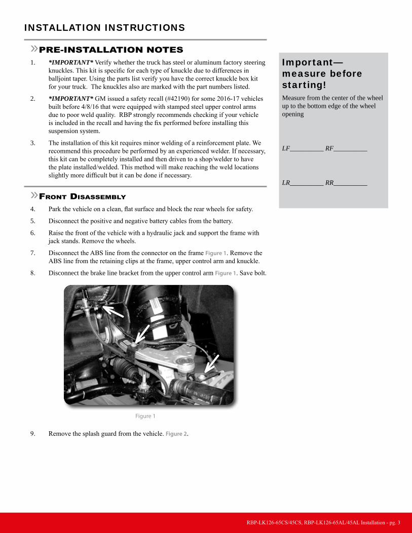
7. Disconnect the ABS line from the connector on the frame Figure 1. Remove the ABS line from the retaining clips at the frame, upper control arm and knuckle.
8. Disconnect the brake line bracket from the upper control arm Figure 1. Save bolt.
Figure 1
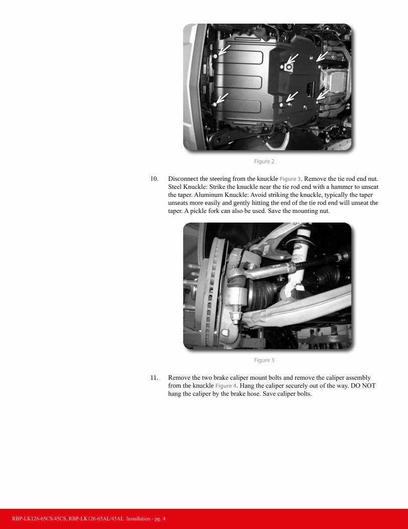
9. Remove the splash guard from the vehicle. Figure 2.
Important—measure before starting!Measure from the center of the wheel up to the bottom edge of the wheel opening
LF__________ RF__________
LR__________ RR__________
RBP-LK126-65CS/45CS, RBP-LK126-65AL/45AL Installation - pg. 4
Figure 2
10. Disconnect the steering from the knuckle Figure 3. Remove the tie rod end nut. Steel Knuckle: Strike the knuckle near the tie rod end with a hammer to unseat the taper. Aluminum Knuckle: Avoid striking the knuckle, typically the taper unseats more easily and gently hitting the end of the tie rod end will unseat the taper. A pickle fork can also be used. Save the mounting nut.
Figure 3
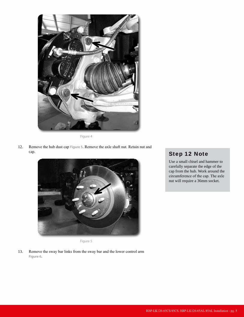
11. Remove the two brake caliper mount bolts and remove the caliper assembly from the knuckle Figure 4. Hang the caliper securely out of the way. DO NOT hang the caliper by the brake hose. Save caliper bolts.
RBP-LK126-65CS/45CS, RBP-LK126-65AL/45AL Installation - pg. 5
Figure 4
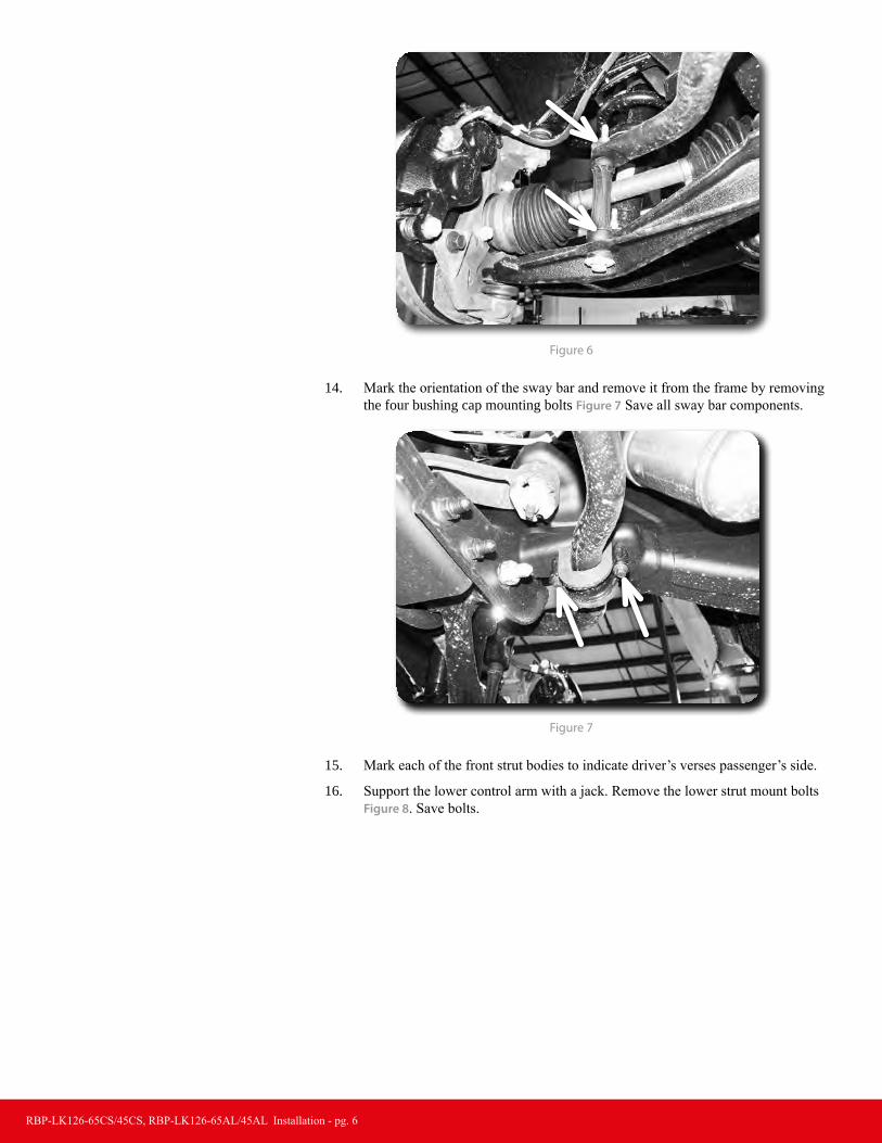
12. Remove the hub dust cap Figure 5. Remove the axle shaft nut. Retain nut and cap.
Figure 5
13. Remove the sway bar links from the sway bar and the lower control arm Figure 6.
Step 12 NoteUse a small chisel and hammer to carefully separate the edge of the cap from the hub. Work around the circumference of the cap. The axle nut will require a 36mm socket.
RBP-LK126-65CS/45CS, RBP-LK126-65AL/45AL Installation - pg. 6
Figure 6
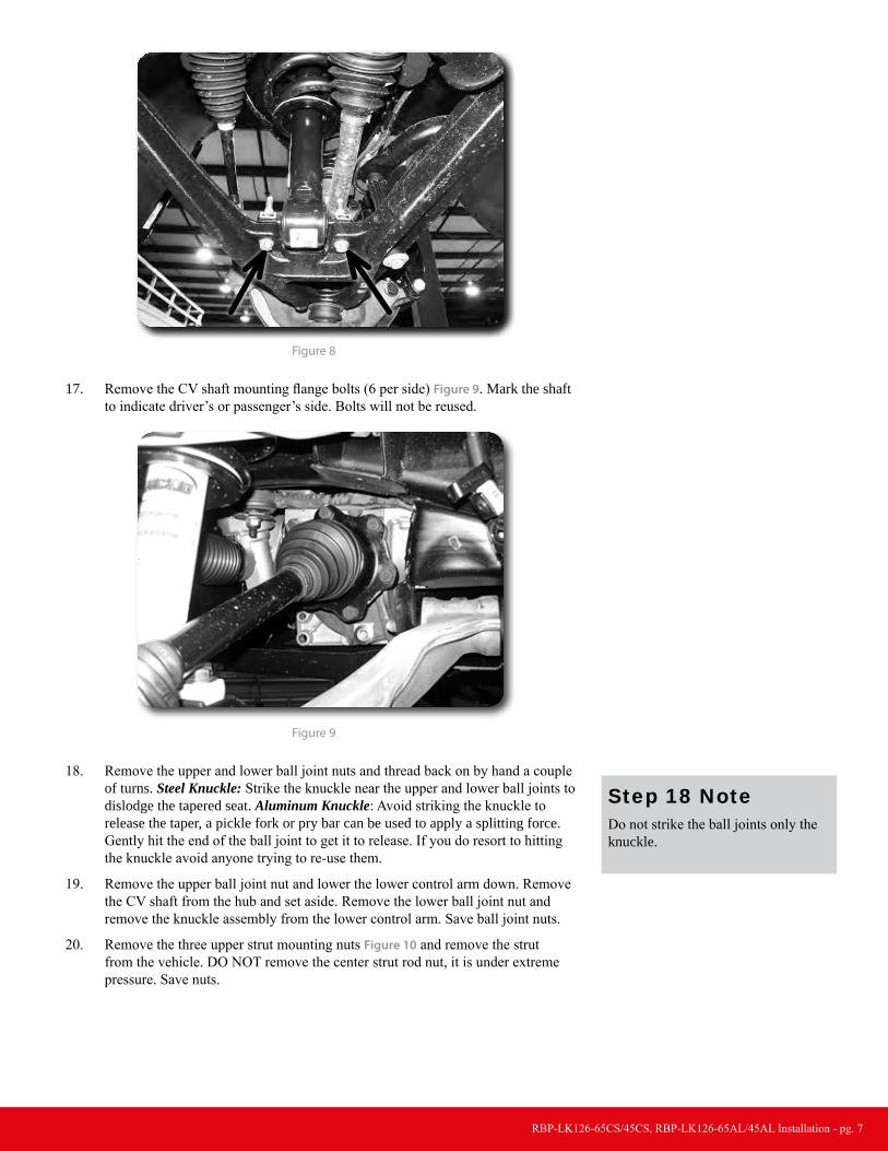
14. Mark the orientation of the sway bar and remove it from the frame by removing the four bushing cap mounting bolts Figure 7 Save all sway bar components.
Figure 7
15. Mark each of the front strut bodies to indicate driver’s verses passenger’s side.
16. Support the lower control arm with a jack. Remove the lower strut mount bolts Figure 8. Save bolts.
RBP-LK126-65CS/45CS, RBP-LK126-65AL/45AL Installation - pg. 7
Figure 8
17. Remove the CV shaft mounting flange bolts (6 per side) Figure 9. Mark the shaft to indicate driver’s or passenger’s side. Bolts will not be reused.
Figure 9
18. Remove the upper and lower ball joint nuts and thread back on by hand a couple of turns. Steel Knuckle: Strike the knuckle near the upper and lower ball joints to dislodge the tapered seat. Aluminum Knuckle: Avoid striking the knuckle to release the taper, a pickle fork or pry bar can be used to apply a splitting force. Gently hit the end of the ball joint to get it to release. If you do resort to hitting the knuckle avoid anyone trying to re-use them.
19. Remove the upper ball joint nut and lower the lower control arm down. Remove the CV shaft from the hub and set aside. Remove the lower ball joint nut and remove the knuckle assembly from the lower control arm. Save ball joint nuts.
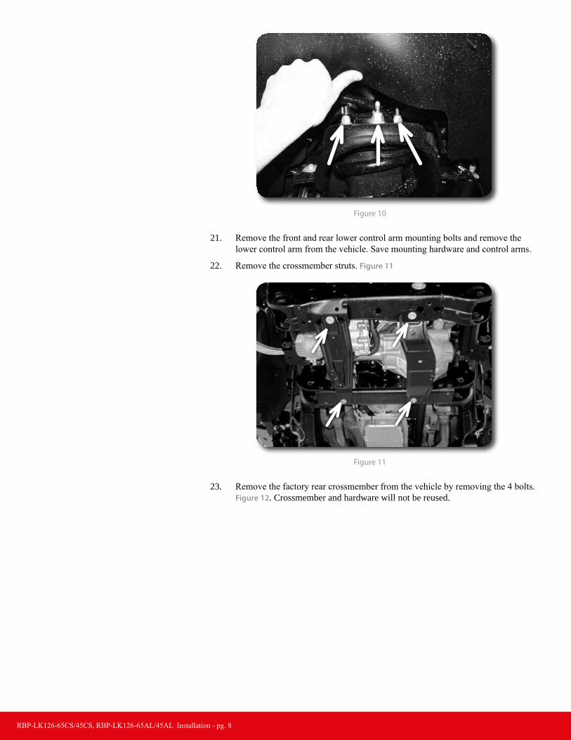
20. Remove the three upper strut mounting nuts Figure 10 and remove the strut from the vehicle. DO NOT remove the center strut rod nut, it is under extreme pressure. Save nuts.
Step 18 NoteDo not strike the ball joints only the knuckle.
RBP-LK126-65CS/45CS, RBP-LK126-65AL/45AL Installation - pg. 8
Figure 10
21. Remove the front and rear lower control arm mounting bolts and remove the lower control arm from the vehicle. Save mounting hardware and control arms.
22. Remove the crossmember struts. Figure 11
Figure 11
23. Remove the factory rear crossmember from the vehicle by removing the 4 bolts. Figure 12. Crossmember and hardware will not be reused.

RBP-LK126-65CS/45CS, RBP-LK126-65AL/45AL Installation - pg. 9
Fgure 12
24. Make an alignment mark to show the relationship between the front driveshaft and the differential input flange. Remove the four driveshaft bolts and disconnect the driveshaft from the differential. Save bolts. Figure 13
Figure 13
25. The driver’s side rear lower control arm pocket must be cut to provide clearance for the front differential in the relocated position. This also aids in the removal of the differential. This area needs to be cleaned of any oil, grease and/or undercoating. These coatings are flammable.
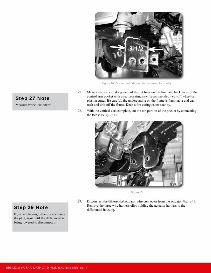
26. Measure from the inside of the driver's side control arm pocket out 3-1/2" and mark. Repeat this measurement on the opposite side of the pocket. Make vertical cut lines at the 3-1/2” mark up both front and back faces of the pocket Figure 14.
Step 25 NotesA putty knife and parts cleaning solvent work well to remove under-coating.
RBP-LK126-65CS/45CS, RBP-LK126-65AL/45AL Installation - pg. 10
3-1/2
Figure 14 - Shown with differential removed for clarity
27. Make a vertical cut along each of the cut lines on the front and back faces of the control arm pocket with a reciprocating saw (recommended), cut-off wheel or plasma cutter. Be careful, the undercoating on the frame is flammable and can melt and drip off the frame. Keep a fire extinguisher near by.
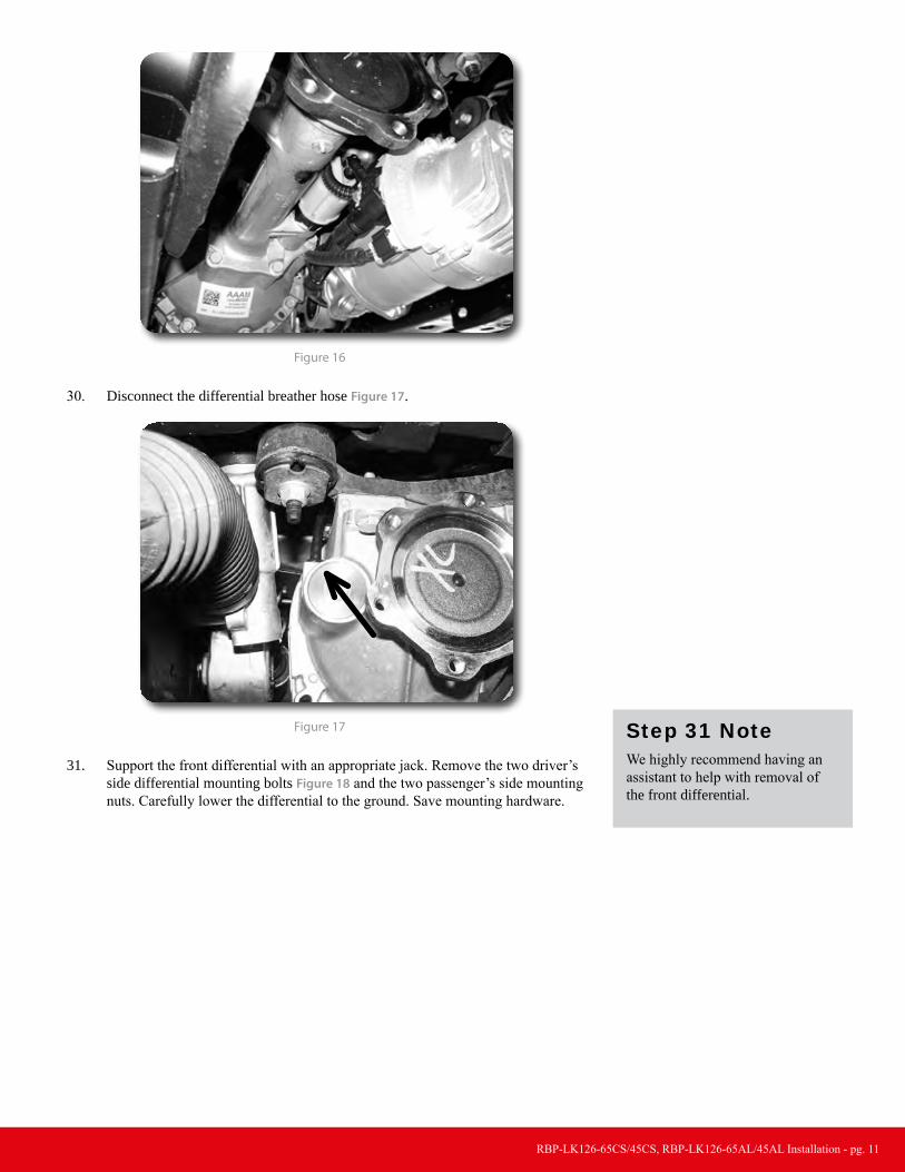
28. With the vertical cuts complete, cut the top portion of the pocket by connecting the two cuts Figure 15.
Figure 15
29. Disconnect the differential actuator wire connector from the actuator Figure 16. Remove the three wire harness clips holding the actuator harness to the differential housing.
Step 27 NoteMeasure twice, cut once!!!
Step 29 NoteIf you are having difficulty accessing the plug, wait until the differential is being lowered to disconnect it.
RBP-LK126-65CS/45CS, RBP-LK126-65AL/45AL Installation - pg. 11
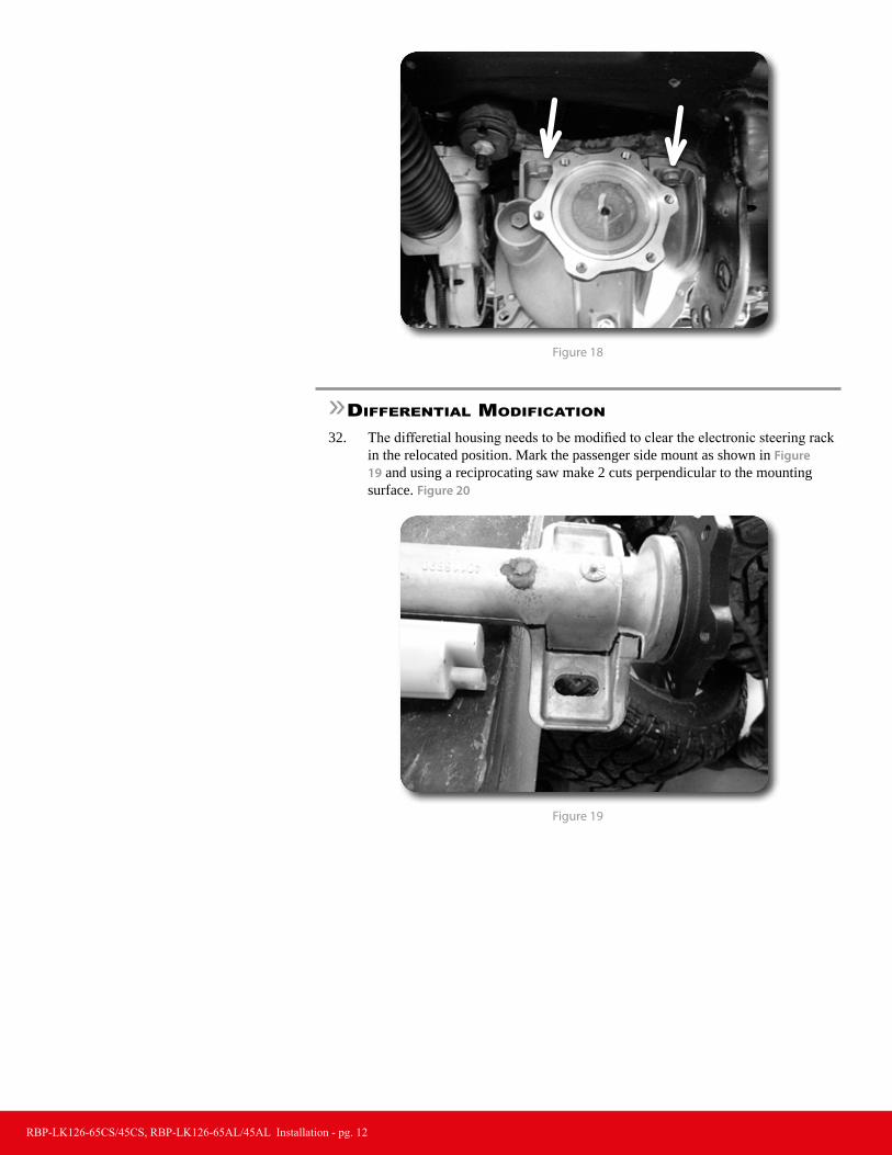
Figure 16
30. Disconnect the differential breather hose Figure 17.
Figure 17
31. Support the front differential with an appropriate jack. Remove the two driver’s side differential mounting bolts Figure 18 and the two passenger’s side mounting nuts. Carefully lower the differential to the ground. Save mounting hardware.
Step 31 NoteWe highly recommend having an assistant to help with removal of the front differential.
RBP-LK126-65CS/45CS, RBP-LK126-65AL/45AL Installation - pg. 12
Figure 18
»differential modification
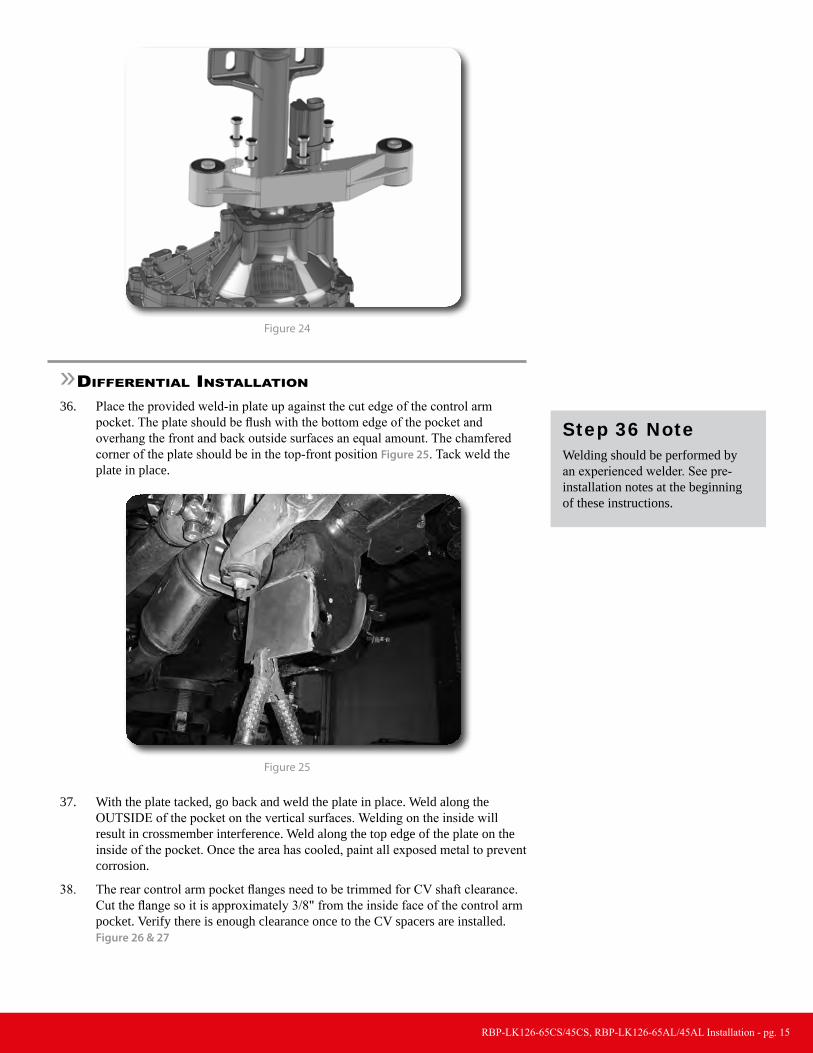
32. The differetial housing needs to be modified to clear the electronic steering rack in the relocated position. Mark the passenger side mount as shown in Figure 19 and using a reciprocating saw make 2 cuts perpendicular to the mounting surface. Figure 20
Figure 19

RBP-LK126-65CS/45CS, RBP-LK126-65AL/45AL Installation - pg. 13
Figure 20
33. Clean up the cuts with a sanding disc or flap wheel. Be sure to remove the remaining material on the outside flange so it matches the rest of the contour. Figure 21
Figure 21
34. The rear side of this mount also needs to be trimmed. Measure 1" from the center of the slot and mark a cut line. Figure 22 Using a reciprocating saw, cut at the line Figure 23.

RBP-LK126-65CS/45CS, RBP-LK126-65AL/45AL Installation - pg. 14
1"
Cut Line
Figure 22
Figure 23
35. Locate the center differential bracket and 10mm x 40mm bolts and washers. Remove the 4 housing bolts and install the differential bracket with the provided hardware using some loctite. Torque bolts to 33 ft-lbs. Take care not to break the gasket seal. Figure 24.
Step 35 NoteDifferential mount hardware is lo-cated in Diff. Brackets pack.
RBP-LK126-65CS/45CS, RBP-LK126-65AL/45AL Installation - pg. 15
Figure 24
»differential inStallation
36. Place the provided weld-in plate up against the cut edge of the control arm pocket. The plate should be flush with the bottom edge of the pocket and overhang the front and back outside surfaces an equal amount. The chamfered corner of the plate should be in the top-front position Figure 25. Tack weld the plate in place.
Figure 25
37. With the plate tacked, go back and weld the plate in place. Weld along the OUTSIDE of the pocket on the vertical surfaces. Welding on the inside will result in crossmember interference. Weld along the top edge of the plate on the inside of the pocket. Once the area has cooled, paint all exposed metal to prevent corrosion.
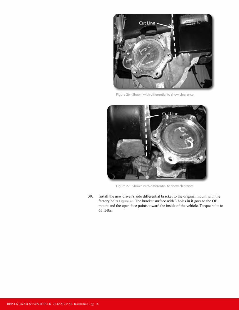
38. The rear control arm pocket flanges need to be trimmed for CV shaft clearance. Cut the flange so it is approximately 3/8" from the inside face of the control arm pocket. Verify there is enough clearance once to the CV spacers are installed. Figure 26 & 27
Step 36 NoteWelding should be performed by an experienced welder. See pre-installation notes at the beginning of these instructions.
RBP-LK126-65CS/45CS, RBP-LK126-65AL/45AL Installation - pg. 16
Cut Line
Figure 26 - Shown with differential to show clearance
Cut Line
Figure 27 - Shown with differential to show clearance
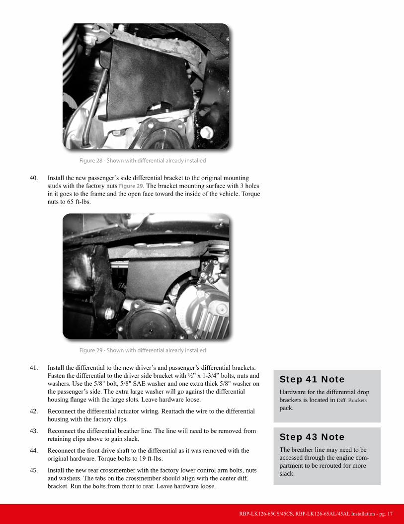
39. Install the new driver’s side differential bracket to the original mount with the factory bolts Figure 28. The bracket surface with 3 holes in it goes to the OE mount and the open face points toward the inside of the vehicle. Torque bolts to 65 ft-lbs.
RBP-LK126-65CS/45CS, RBP-LK126-65AL/45AL Installation - pg. 17
Figure 28 - Shown with differential already installed
40. Install the new passenger’s side differential bracket to the original mounting studs with the factory nuts Figure 29. The bracket mounting surface with 3 holes in it goes to the frame and the open face toward the inside of the vehicle. Torque nuts to 65 ft-lbs.
Figure 29 - Shown with differential already installed
41. Install the differential to the new driver’s and passenger’s differential brackets. Fasten the differential to the driver side bracket with ½” x 1-3/4” bolts, nuts and washers. Use the 5/8" bolt, 5/8" SAE washer and one extra thick 5/8" washer on the passenger’s side. The extra large washer will go against the differential housing flange with the large slots. Leave hardware loose.
42. Reconnect the differential actuator wiring. Reattach the wire to the differential housing with the factory clips.
43. Reconnect the differential breather line. The line will need to be removed from retaining clips above to gain slack.
44. Reconnect the front drive shaft to the differential as it was removed with the original hardware. Torque bolts to 19 ft-lbs.
45. Install the new rear crossmember with the factory lower control arm bolts, nuts and washers. The tabs on the crossmember should align with the center diff. bracket. Run the bolts from front to rear. Leave hardware loose.
Step 41 NoteHardware for the differential drop brackets is located in Diff. Brackets pack.
Step 43 NoteThe breather line may need to be accessed through the engine com-partment to be rerouted for more slack.

RBP-LK126-65CS/45CS, RBP-LK126-65AL/45AL Installation - pg. 18
46. Install the front crossmember in the control arm pockets with the factory lower control arm bolts, nuts and washers. When installed the offset in the crossmember ends should be toward the front of the vehicle. Run bolts from front to rear. Leave hardware loose.
47. Install the 9/16" x 4" bolts in the center differential bracket at the front and rear crossmembers. Torque All differential mount hardware: 1/2” hardware to 65 ft-lbs, 9/16" hardware to 90 ft-lbs and the 5/8" hardware to 120 ft-lbs.
48. Attach the provided differential skid plate to the front and rear crossmembers with three 1/2" x 1-1/4" bolts and 1/2" SAE washers in the threaded holes in the crossmembers. Use Loctite on all skid plate bolts. Leave hardware loose.
49. Attach the provided crossmember support strut to the front and rear crossmembers with 1/2" x 1-1/4" bolts and 1/2" SAE washers in the passenger side outer threaded holes in the front and rear crossmembers. The ends of the support strut are bent to set flush with the bottoms of the crossmembers Use Loctite on the bolts. Leave hardware loose.
50. Install the OE lower control arms in the new crossmembers and fasten with 5/8” x 4-1/2” (front) and 5/8” x 5-1/2” (rear) bolts, nuts and 5/8” SAE washers. Run the bolts from front to rear. Leave hardware loose.
51. With the crossmembers, control arms, skid plate and support strut installed, go back and torque the crossmember mounting bolts to 125 ft-lbs and the skid plate/support strut hardware to 65 ft-lbs.
»Strut & Steering KnucKle inStallation
52. Install the provided strut spacers on the struts with provided nuts and washers. The spacers will only install one way. Torque the hardware to 30 ft-lbs. Figure 30
Figure 30
53. Install the new strut assembly to the appropriate frame mount with the factory flange nuts. Leave hardware loose.
54. Swing the lower control arm up to the strut and fasten it with the original mounting bolts. Torque lower and upper strut hardware to 40 ft-lbs.
55. Remove the hub bearing/rotor assembly and brake dust shield from the factory steering knuckles. Be sure to note which hub goes on which side of the vehicle. Save mounting bolts.
56. The brake dust shield needs to be trimmed. Measure in from the lower vertical edge (opposite the ABS sensor location) 1/2” and make a straight line to the edge shown in Figure 31. Cut the section off of the brake dust shield.
Step 48-49 NoteHardware for the differential skid plate and crossmember support strut is located in ABS/Skid Plate pack. If installing the optional front skid plate do so at this time.
Step 50 NoteHardware for the lower control arms is located in Crossmembers pack.
Step 52 NoteHardware for the strut spacers is located in Strut Spacers pack.
RBP-LK126-65CS/45CS, RBP-LK126-65AL/45AL Installation - pg. 19
1/2"
Figure 31
57. Install the modified dust shield and hub/rotor in the corresponding new knuckles. Fasten the hub/shield with the OE bolts. Apply Loctite to the bolt threads and torque to 133 ft-lbs. Be sure that the ABS line is run properly through the dust shield and out above the steering arm on the knuckle.
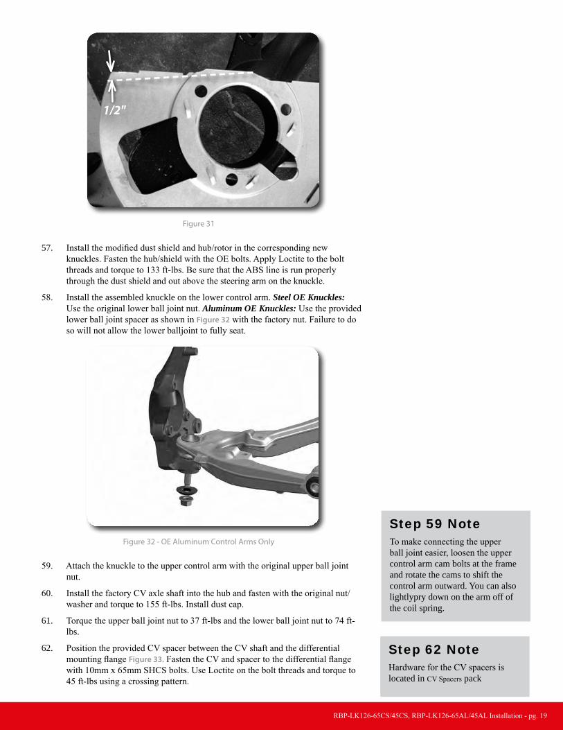
58. Install the assembled knuckle on the lower control arm. Steel OE Knuckles: Use the original lower ball joint nut. Aluminum OE Knuckles: Use the provided lower ball joint spacer as shown in Figure 32 with the factory nut. Failure to do so will not allow the lower balljoint to fully seat.
Figure 32 - OE Aluminum Control Arms Only
59. Attach the knuckle to the upper control arm with the original upper ball joint nut.
60. Install the factory CV axle shaft into the hub and fasten with the original nut/washer and torque to 155 ft-lbs. Install dust cap.
61. Torque the upper ball joint nut to 37 ft-lbs and the lower ball joint nut to 74 ft-lbs.
62. Position the provided CV spacer between the CV shaft and the differential mounting flange Figure 33. Fasten the CV and spacer to the differential flange with 10mm x 65mm SHCS bolts. Use Loctite on the bolt threads and torque to 45 ft-lbs using a crossing pattern.
Step 59 NoteTo make connecting the upper ball joint easier, loosen the upper control arm cam bolts at the frame and rotate the cams to shift the control arm outward. You can also lightlypry down on the arm off of the coil spring.
Step 62 NoteHardware for the CV spacers is located in CV Spacers pack

RBP-LK126-65CS/45CS, RBP-LK126-65AL/45AL Installation - pg. 20
Figure 33
63. Working on one side at a time, remove the tie rod end from the steering link.Trim 5/8" off the tie rod end so the end to center measurement is approximately 4-7/8". Figure 34. Trim only 1/2" off of the steering link for maximum thread engagement. Figure 35 Once the two pieces are trimmed, clean the ends of the threads and reinstall the tie rod end on the steering link so there is about 1/8" of threads showing on the steering link. Repeat on other side of the vehicle.
5/8"
~4-7/8"
Cut Line
Figure 34
Cut 1/2" Off Threads
Figure 35
Step 63 NoteLeave the nut on the steering link during cutting. This can then be used to clean up the ver the threads if necessary
RBP-LK126-65CS/45CS, RBP-LK126-65AL/45AL Installation - pg. 21
64. Remove the retaining clip and slide the brake line through the bracket. To avoid having to bleed the brakes, cut an opening in the factory brake line bracket so the bracket can be removed from the line. Take care not to kink the brake line. Disconnect the bracket from the frame. Save hardware.
65. Attach the caliper to the new steering knuckle with the original mounting hardware. Torque bolts to 125 ft-lbs.
66. Carefully remove the metal retainer bracket from the factory rubber brake line. This can be done with two vice grips, pliers, or crescent wrenches.
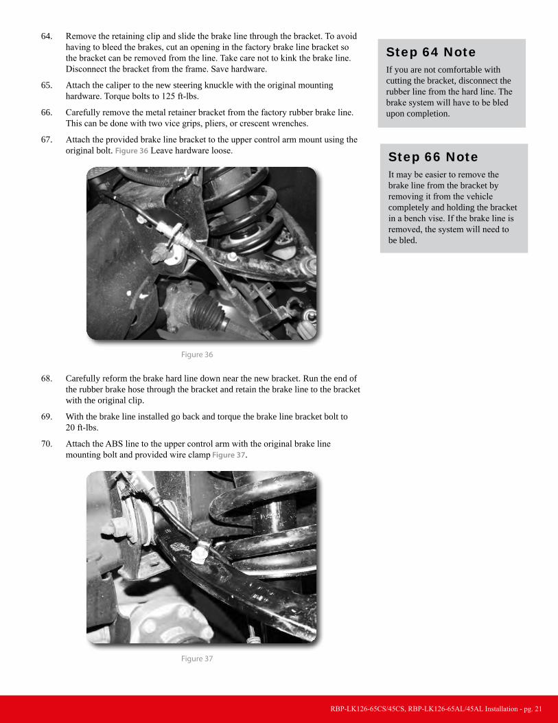
67. Attach the provided brake line bracket to the upper control arm mount using the original bolt. Figure 36 Leave hardware loose.
Figure 36
68. Carefully reform the brake hard line down near the new bracket. Run the end of the rubber brake hose through the bracket and retain the brake line to the bracket with the original clip.
69. With the brake line installed go back and torque the brake line bracket bolt to 20 ft-lbs.
70. Attach the ABS line to the upper control arm with the original brake line mounting bolt and provided wire clamp Figure 37.
Figure 37
Step 64 NoteIf you are not comfortable with cutting the bracket, disconnect the rubber line from the hard line. The brake system will have to be bled upon completion.
Step 66 NoteIt may be easier to remove the brake line from the bracket by removing it from the vehicle completely and holding the bracket in a bench vise. If the brake line is removed, the system will need to be bled.

RBP-LK126-65CS/45CS, RBP-LK126-65AL/45AL Installation - pg. 22
71. Reconnect ABS line at the frame. Attach the ABS line to the steering knuckle with the provided wire clamps and ¼” x ¾” self tapping bolt and flat washer. Torque bolt to 15 ft-lbs. Use zip ties to retain the remaining section of the ABS line as needed to keep it away from rotating objects Figure 38.
Figure 38
72. Attach the front sway bar to the original mounts in the stock orientation in conjunction with the provided drop brackets and 10mm x 130mm bolts/washers for 6.5" kits or 10mm x 80mm bolts for 4.5" kits . Use Loctite on the bolt threads and torque to 45 ft-lbs Figure 39.
Figure 39
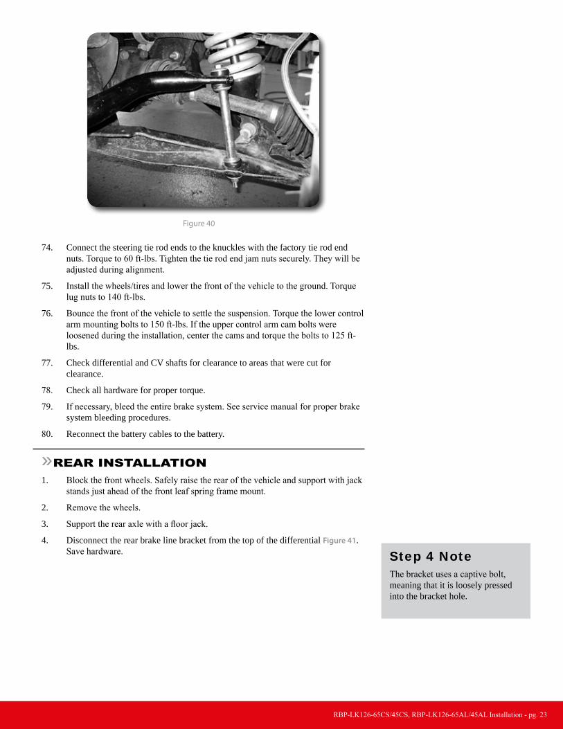
73. The new sway bar links will be built from a 5" sleeve, 3/8" x 9" bolt, bushings and cup washers. Attach these to the sway bar followed by the control arm wih the bolt going from the top down. Figure 40 Tighten the sway bar link until the bushings begin to form to the control arm surface.
Step 71 NoteHardware for the brake line clamps is located in bolt pack 447.
Step 72 NoteHardware for the sway bar drops is located in ABS/Skid Plate pack for 6.5" kits. For 4.5" kits use the 10mm bolts supplied in the bag kit with the drop spacers.
RBP-LK126-65CS/45CS, RBP-LK126-65AL/45AL Installation - pg. 23
Figure 40
74. Connect the steering tie rod ends to the knuckles with the factory tie rod end nuts. Torque to 60 ft-lbs. Tighten the tie rod end jam nuts securely. They will be adjusted during alignment.
75. Install the wheels/tires and lower the front of the vehicle to the ground. Torque lug nuts to 140 ft-lbs.
76. Bounce the front of the vehicle to settle the suspension. Torque the lower control arm mounting bolts to 150 ft-lbs. If the upper control arm cam bolts were loosened during the installation, center the cams and torque the bolts to 125 ft-lbs.
77. Check differential and CV shafts for clearance to areas that were cut for clearance.
78. Check all hardware for proper torque.
79. If necessary, bleed the entire brake system. See service manual for proper brake system bleeding procedures.
80. Reconnect the battery cables to the battery.
»rear inStallation1. Block the front wheels. Safely raise the rear of the vehicle and support with jack
stands just ahead of the front leaf spring frame mount.
2. Remove the wheels.
3. Support the rear axle with a floor jack.
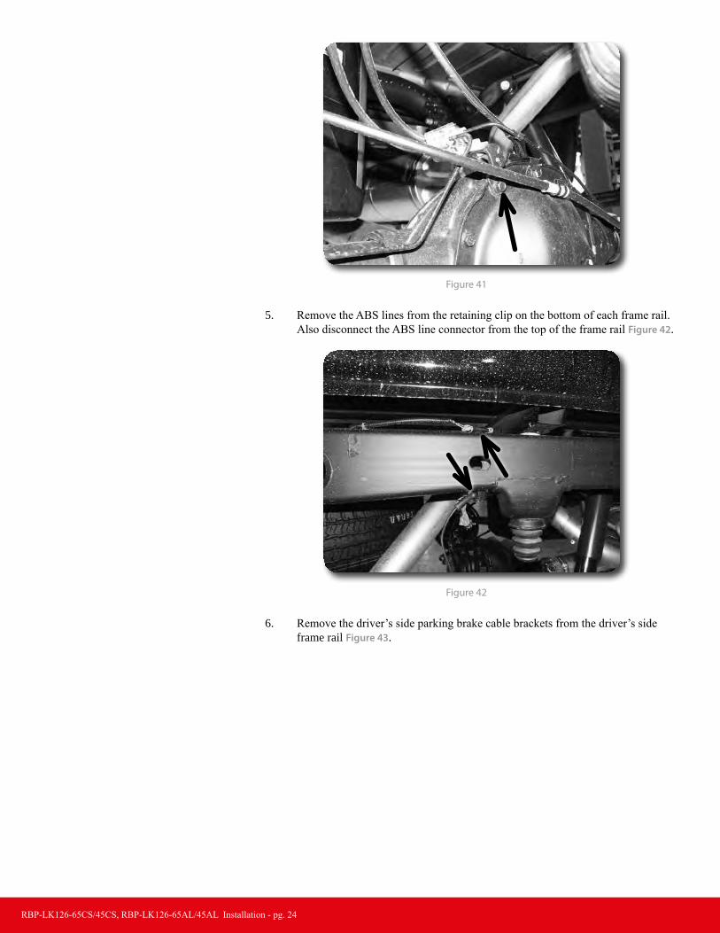
4. Disconnect the rear brake line bracket from the top of the differential Figure 41. Save hardware. Step 4 Note
The bracket uses a captive bolt, meaning that it is loosely pressed into the bracket hole.
RBP-LK126-65CS/45CS, RBP-LK126-65AL/45AL Installation - pg. 24
Figure 41
5. Remove the ABS lines from the retaining clip on the bottom of each frame rail. Also disconnect the ABS line connector from the top of the frame rail Figure 42.
Figure 42
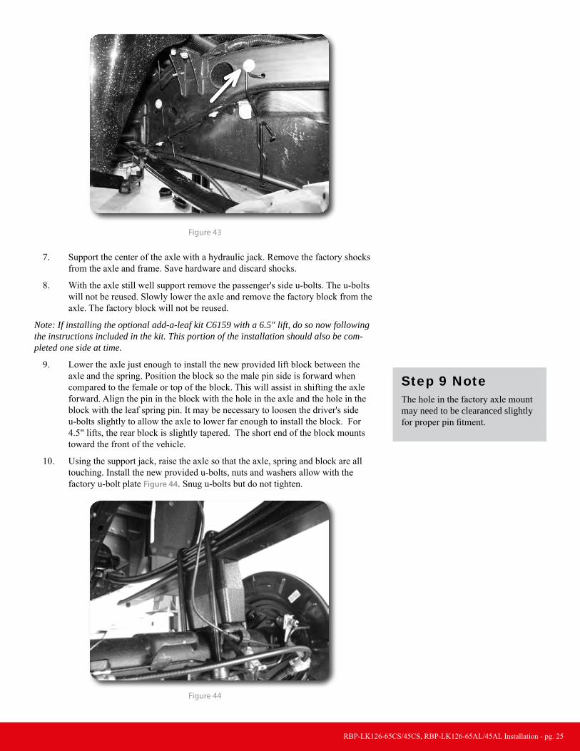
6. Remove the driver’s side parking brake cable brackets from the driver’s side frame rail Figure 43.
RBP-LK126-65CS/45CS, RBP-LK126-65AL/45AL Installation - pg. 25
Figure 43
7. Support the center of the axle with a hydraulic jack. Remove the factory shocks from the axle and frame. Save hardware and discard shocks.
8. With the axle still well support remove the passenger's side u-bolts. The u-bolts will not be reused. Slowly lower the axle and remove the factory block from the axle. The factory block will not be reused.
Note: If installing the optional add-a-leaf kit C6159 with a 6.5" lift, do so now following the instructions included in the kit. This portion of the installation should also be com-pleted one side at time.
9. Lower the axle just enough to install the new provided lift block between the axle and the spring. Position the block so the male pin side is forward when compared to the female or top of the block. This will assist in shifting the axle forward. Align the pin in the block with the hole in the axle and the hole in the block with the leaf spring pin. It may be necessary to loosen the driver's side u-bolts slightly to allow the axle to lower far enough to install the block. For 4.5" lifts, the rear block is slightly tapered. The short end of the block mounts toward the front of the vehicle.
10. Using the support jack, raise the axle so that the axle, spring and block are all touching. Install the new provided u-bolts, nuts and washers allow with the factory u-bolt plate Figure 44. Snug u-bolts but do not tighten.
Figure 44
Step 9 NoteThe hole in the factory axle mount may need to be clearanced slightly for proper pin fitment.
RBP-LK126-65CS/45CS, RBP-LK126-65AL/45AL Installation - pg. 26
11. Repeat the installation on the driver's side of the vehicle. Pay special attention to all of the brake lines and wires. Do not allow them to get over-extended.
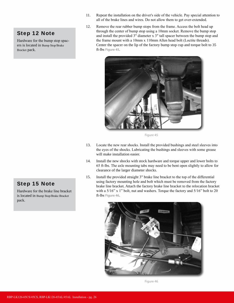
12. Remove the rear rubber bump stops from the frame. Access the bolt head up through the center of bump stop using a 10mm socket. Remove the bump stop and install the provided 3" diameter x 3" tall spacer between the bump stop and the frame mount with a 10mm x 110mm Allen head bolt (Loctite threads). Center the spacer on the lip of the factory bump stop cup and torque bolt to 35 ft-lbs Figure 45.
Figure 45
13. Locate the new rear shocks. Install the provided bushings and steel sleeves into the eyes of the shocks. Lubricating the bushings and sleeves with some grease will make installation easier.
14. Install the new shocks with stock hardware and torque upper and lower bolts to 65 ft-lbs. The axle mounting tabs may need to be bent open slightly to allow for clearance of the larger diameter shocks.
15. Install the provided straight 3" brake line bracket to the top of the differential using factory mounting hole and bolt which must be removed from the factory brake line bracket. Attach the factory brake line bracket to the relocation bracket with a 5/16” x 1” bolt, nut and washers. Torque the factory and 5/16” bolt to 20 ft-lbs Figure 46.
Figure 46
Step 12 NoteHardware for the bump stop spac-ers is located in Bump Stop/Brake Bracket pack.
Step 15 NoteHardware for the brake line bracket is located in Bump Stop/Brake Bracket pack.
RBP-LK126-65CS/45CS, RBP-LK126-65AL/45AL Installation - pg. 27
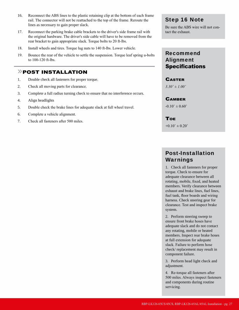
16. Reconnect the ABS lines to the plastic retaining clip at the bottom of each frame rail. The connector will not be reattached to the top of the frame. Reroute the lines as necessary to gain proper slack.
17. Reconnect the parking brake cable brackets to the driver's side frame rail with the original hardware. The driver's side cable will have to be removed from the rear bracket to gain appropriate slack. Torque bolts to 20 ft-lbs.
18. Install wheels and tires. Torque lug nuts to 140 ft-lbs. Lower vehicle.
19. Bounce the rear of the vehicle to settle the suspension. Torque leaf spring u-bolts to 100-120 ft-lbs.
»PoSt inStallation1. Double check all fasteners for proper torque.
2. Check all moving parts for clearance.
3. Complete a full radius turning check to ensure that no interference occurs.
4. Align headlights
5. Double check the brake lines for adequate slack at full wheel travel.
6. Complete a vehicle alignment.
7. Check all fasteners after 500 miles.
Step 16 NoteBe sure the ABS wire will not con-tact the exhaust.
Recommend Alignment Specifications
caSter 3.30˚ ± 1.00˚
camber
-0.10˚ ± 0.60˚
toe
+0.10˚ ± 0.20˚
Post-Installation Warnings1. Check all fasteners for proper torque. Check to ensure for adequate clearance between all rotating, mobile, fixed, and heated members. Verify clearance between exhaust and brake lines, fuel lines, fuel tank, floor boards and wiring harness. Check steering gear for clearance. Test and inspect brake system.
2. Perform steering sweep to ensure front brake hoses have adequate slack and do not contact any rotating, mobile or heated members. Inspect rear brake hoses at full extension for adequate slack. Failure to perform hose check/ replacement may result in component failure.
3. Perform head light check and adjustment.
4. Re-torque all fasteners after 500 miles. Always inspect fasteners and components during routine servicing.


![ROP is Still Dangerous - USENIX · pop rbx pop rbp ret . Normal Execution and [rax],0xfd mov edx,0x768 mov esi,0x4ab632 mov rdi,rbx call 0x2b2130 test rbp,rbp cmov [rbp],0x0 add rsp,0x8](https://static.fdocuments.in/doc/165x107/5ffcfe1846f16d3fff4c6e50/rop-is-still-dangerous-usenix-pop-rbx-pop-rbp-ret-normal-execution-and-rax0xfd.jpg)