RBI, 2004 DOC #RBIFV3HL Westfield, MA 01085mesteksa.com/fileuploads/Literature/RBI Water...
32
RBI, 2004 DOC #RBIFV3HL 260 N. Elm St. Westfield, MA 01085 12/19/16 1 RBI H-NET V3 Control Firmware Revision Sheet 19 - DEC - 2016 Release Control Firmware Revision 2.51 - 2.54 1. Corrected an issue where a saved setting was updated too frequently when using an LCD color display. The result of this was a damaged storage block in the EEPROM saved settings memory. The EEPROM has a limited amount of times that it can be written to before being damaged. When the saved byte’s cells were damaged, the result was that it took out the whole block of 256 bytes associated with it. This resulted in adjacent save locations being damaged. With this release, the 256 byte block that is affected is marked bad and the saved settings are moved to an adjacent free block. The damaged save locations could cause errant operation. These locations are not damaged when using the 4-line green Vacuum Florescent display and operation will be normal. The affected saved settings were: Heat Exchanger Return Water Temperature Return Threshold Temp (takes a boiler offline if the Return temp is less than above temp) DHW Max Runtime DHW Holdoff Time (used to prevent the boiler from staying too long in DHW mode) Force a Firmware file to be loaded ( causes No Communications with the LCD) 2. Removed support for the KB Variable frequency drive at 110Hz. LCD Touch Display Firmware Revision 1.2-R8 No Changes 30 - Nov - 2016 Release Control Firmware Revision 2.50 No Changes LCD Touch Display Firmware Revision 1.2-R8 1. Fixed issue with SNTP (Network Time) that caused incorrect time on the Display and HeatNet control when HeatNet Online was enabled. 2. Added improved DHW operation display. 3. Added Data Capture feature which can be used to periodically save a predefined set of temperatures and operational data to a USB drive. The data is saved as comma separated values (CSV) so it can be viewed and analyzed in any application that supports that format. 4 – Nov -2016 Release Control Firmware Revision 2.50
Transcript of RBI, 2004 DOC #RBIFV3HL Westfield, MA 01085mesteksa.com/fileuploads/Literature/RBI Water...

RBI, 2004 DOC #RBIFV3HL
260 N. Elm St.
Westfield, MA 01085
12/19/16 1
RBI H-NET V3 Control Firmware Revision Sheet
19 - DEC - 2016 Release
Control Firmware Revision 2.51 - 2.54
1. Corrected an issue where a saved setting was updated too frequently when using an LCD color display. The
result of this was a damaged storage block in the EEPROM saved settings memory. The EEPROM has a
limited amount of times that it can be written to before being damaged. When the saved byte’s cells were
damaged, the result was that it took out the whole block of 256 bytes associated with it. This resulted in
adjacent save locations being damaged.
With this release, the 256 byte block that is affected is marked bad and the saved settings are moved to an
adjacent free block.
The damaged save locations could cause errant operation. These locations are not damaged when using the
4-line green Vacuum Florescent display and operation will be normal.
The affected saved settings were:
Heat Exchanger Return Water Temperature
Return Threshold Temp (takes a boiler offline if the Return temp is less than above temp)
DHW Max Runtime
DHW Holdoff Time (used to prevent the boiler from staying too long in DHW mode)
Force a Firmware file to be loaded ( causes No Communications with the LCD)
2. Removed support for the KB Variable frequency drive at 110Hz.
LCD Touch Display Firmware Revision 1.2-R8
No Changes
30 - Nov - 2016 Release
Control Firmware Revision 2.50
No Changes
LCD Touch Display Firmware Revision 1.2-R8
1. Fixed issue with SNTP (Network Time) that caused incorrect time on the Display and HeatNet control when
HeatNet Online was enabled.
2. Added improved DHW operation display.
3. Added Data Capture feature which can be used to periodically save a predefined set of temperatures and
operational data to a USB drive. The data is saved as comma separated values (CSV) so it can be viewed
and analyzed in any application that supports that format.
4 – Nov -2016 Release
Control Firmware Revision 2.50
RBI, 2004 DOC #RBIFV3HL
260 N. Elm St.
Westfield, MA 01085
12/19/16 2
1. Added a DHW Override Mode with Sensor as a supplement to DHW Mode 4, which will now be designated
as Mode 4B. This mode was originally in the HeatNet Version 2 board firmware, but was not migrated over
to Version 3.
This mode is only available on the Master boiler since it’s purpose is to override the system setpoint. In
this mode the space heating setpoint (Header) is overridden with the DHW setpoint, and the DHW
temperature is maintained at the DHW sensor using the DHW pump. The Master boiler will only control the
DHW pump and allow all boilers to fire to maintain the DHW setpoint. The OA OVR input and the Heat
Demand input must be closed to enable this mode. If either of these inputs are opened, the mode will be
stopped.
All boilers are started and stopped using the space heating Modular Boiler Settings. The Modular Boiler
DHW tab is not available.
In prior versions, Method 2 was only allowed in this application. This method required setting the
Distributed Control: Master Type: to Combo along with the DHW (Boiler Mode): set to Combo on each
boiler used for DHW heating. Using this mode allowed a DHW failsafe mode and pump redundancy. The
limitation in this mode was that all DHW pumps needed to be wired in parallel. If the Master was the only
boiler allowed to control the DHW pump, all other boilers needed to have their respective DHW (Boiler
Mode): set to AUTO. This limited the system to only one boiler controlling the DHW heating load and no
failsafe operation.
With this release and the LCD Touch panel firmware release, the Master will only show a showerhead
indicating the system is running in DHW override. Member boilers will not show the showerhead since they
are unaware of the task the Master is performing.
Settings: Distributed Control: Master Type: AUTO
DHW( Boiler Mode): AUTO
DHW: Use Sensor
2. Added a DHW pump stays on feature which can be used with the DHW Override Mode with sensor.
3. Disabled the Auto detection feature for the OA sensor due to false detections. The OA sensor will have to be
manually enabled in the sensor menu.
4. Fixed issue with saving the Number of System Pumps and the System Pump Rotation on LCD
Display. Previously it could take up to an hour before they were saved.
5. Added the ability to disable the DHW Max Runtime by setting it to 0.
LCD Touch Display Firmware Revision 1.2-R7
1. Added support for new DHW mode as outline above.
24 - August - 2016 Release
Control Firmware Revision 2.46-2.47
1. Fixed an issue that could cause control to reboot when a Modbus “Read Device Identification” request is
sent by the BMS.
2. If the Master Pump/Valve Remains on is set to ON or Always Enabled is set to ON (in the local pump
settings), the boiler will always look for flow. With this release and in this case, the flow is not monitored
when there is no call for heat.
LCD Touch Display Firmware Revision 1.2-R6
No Changes
1 - August 2016 Pre-Release
RBI, 2004 DOC #RBIFV3HL
260 N. Elm St.
Westfield, MA 01085
12/19/16 3
Control Firmware Revision 2.45
1. Added the ability to auto detect the Manager in a multi heat exchanger boiler.
2. Allow the MBMW 500 to be selected. This was removed in prior releases due to Category 1 boiler changes.
LCD Touch Display Firmware Revision 1.2-R6
No Changes
20 – July - 2016 Release
Control Firmware Revision 2.45
No Changes
LCD Touch Display Firmware Revision 1.2-R6
1. Added support for CAT1 products (requires Control Firmware 2.42).
28 – June - 2016 Release
Control Firmware Revision 2.45
1. Added improved support for calibrating FlexCore boilers with multiple heat exchangers.
LCD Touch Display Firmware Revision 1.2-R5
1. Added improved support for calibrating FlexCore boilers with multiple heat exchangers.
2. Added HeatNet Online functionality.
22 – June - 2016 Release
Control Firmware Revision 2.44
1. Added Delta T protection while in Calibrate. All firing rates will drop to ½ the called for rate if the Delta T
exceeds the Delta T setting while making calibration settings. If while performing the calibration procedure
the boiler goes into a Delta T protection mode, the flow may need to be increased or the heating load
adjusted to perform the calibration.
LCD Touch Display Firmware Revision 1.2-R4
No Changes.
15 – May - 2016 Release
Control Firmware Revision 2.43
1. Support for FlexCore multiple heat exchangers.
LCD Touch Display Firmware Revision 1.2-R4
No Changes.
5 – May - 2016 Release
Control Firmware Revision 2.42
No Changes.
RBI, 2004 DOC #RBIFV3HL
260 N. Elm St.
Westfield, MA 01085
12/19/16 4
LCD Touch Display Firmware Revision 1.2-R4
1. Added Maximum DHW Runtime Exceeded and LCD Power Reset log entries.
2. Added improved DHW operational status on master and member boilers.
3. Added a button to update the Display Firmware on the "No Communications Screen".
4. Added ability to detect if the display is booting from on board memory (EMMC) instead of the SD card.
This is required to properly handle display switching on products with multiple heat exchangers.
5. Changed minimum DHW hold off time from 0 to 1 minute (60 seconds).
6. Fixed an issue with Open File Dialog which prevented valid matching files, but with different character
casing from showing up in the file list. It is now case insensitive.
7. Fixed an issue with boiler buttons on the main screen. The “too hot” indicator was being displayed when the
operator interlock was open.
3- May- 2016 Release
Control Firmware Revision 2.42
1. An issue occurs since the last release, where the Local Pump will remain on if the Main valve never opens
and an extreme short cycle occurs. Once the boiler fires, the Local Pump resumes normal operation. This has
been corrected to not allow the Local Pump to remain on.
2. If the HeatNet control has a previous companies/ product range firmware installed, it can cause the other
companies product to display non-released products. This has been corrected.
3. Added the ability of a Member boiler to use the DHW MOD-MAX: RELEASE MOD MAX feature to limit
the DHW modes firing rates to the MOD MAX value.
4. Flexcore default calibration values have changed and are now independent of each Flexcore model.
5. Enhance some minibus functions used by the LCD display on Flexcore.
6. Changed the Default DHW timeout to 2 hours from 1 hour, and the Holdoff (retry) to 30 minutes (was
LOCKOUT). This allows the DHW call for heat to occur for a maximum time of 2 hours before shutting
down and sets the wait time before firing in DHW again to 30 minutes.
7. Also, Limited the DHW Holdoff time to 1 minute minimum from 0 minutes due to possible race conditions.
8. Corrected an LCD Display issue when displaying DHW Modulation.
9. Limited the ADAPTIVE MOD: DELAY RELEASE: minimum and default time to 5 Seconds. The
minimum was 0 seconds. If 0 seconds are needed, use the ORIG KN setting rather than ADAPTIVE under
MOD MODE.
10. Version 2.32 through 2.42 has an issue when communications is lost from the Master. If a Member boiler is
currently running when communications is lost, that Member boiler could remain running and act in Failsafe
mode. That Member boiler will maintain the supply temperature using the operating limit.
LCD Touch Display Firmware Revision 1.2-R3
No Changes.
13– Apr - 2016 Pre-Release
Control Firmware Revision 2.39-2.41
1. An issue occurs after the last release where the DHW OR OVR input when toggled in DHW COMBO and
Master Boiler in MASTER TYPE: COMBO, fails to start the next DHW cycle. The Hold-off timer for the
Maximum Runtime of the DHW fails to reset when in LOCKOUT. This change ensures that the Lockout
setting is cleared when the OR OVR is toggled.
2. Fixed an issue when using the VFD pump signal and the Local Pump Always Enabled feature. Prior to this
release, the local pump’s VFD modulation signal would hunt between a low speed and a high speed when
post purging. This has been corrected to provide a stable high speed pump VFD signal at the Max VFD
setting.
RBI, 2004 DOC #RBIFV3HL
260 N. Elm St.
Westfield, MA 01085
12/19/16 5
3. Issue with detecting a missing/open Stack sensor. If a Stack Sensor opens or is removed when it was
installed, the open sensor warning may not occur due to threshold sensing. The threshold has been increased
to allow greater detection.
4. Fixed issues with display modulation during modulation delay and in DHW operation.
5. Fixed issues with stack temperature when a TypeZ sensor is used. The temperature need to be divided by
100.
6. Fixed issues saving Local Pump Always Enabled and Local Pump Delta Temp Enabled.
7. Fixed issues saving System Pump Always Enabled and Override Enabled in Warm Weather Shutdown.
8. Added improved Minibus communications to support multi-heat exchanger units with the LCD boost.
LCD Touch Display Firmware Revision 1.2-R3
No Changes.
10 – FEB - 2016 Pre-Release
Control Firmware Revision 2.38
1. The password now dis-allows changing the setpoint in the main menu run screen (4-line display).
2. Add VFD pump output voltage change to post purge at 80% (8 VDC).
LCD Touch Display Firmware Revision 1.2-R3
No Changes.
19 – Jan - 2016 Release
Control Firmware Revision 2.35 - 2.36
No Changes.
LCD Touch Display Firmware Revision 1.2-R3
1. Added improved support for the LCD Boost interface card when loading control firmware to prevent
unexpected resets.
2. Improved the method used for network restarts to help resolve issues when a network cable is not connected.
3. Fixed issues with editing temperature settings in Celsius.
4. Fixed an issue that occurred when the Display Units (English, Metric) was changed. The change
inadvertently reset the following settings: Analog (4-20ma, 0-10V) Channel Priority, Firing Mode, Damper
Type, Damper Enable, and Alarm Input/Silence.
5. Fixed an issue that occurred when setting the Heat Exchanger Delta Temperature. The upper limit was
incorrectly calculated which limited the ability to increase the value to the correct maximum.
6. Modified boiler buttons so that the modulation percent is only displayed when it is non-zero.
7. Extended Post Purge and Maximum Runtime are now available in Heat Exchanger Settings on FIII firmware
2.37+.
8-Jan-2016 Release
Control Firmware Revision 2.35 - 2.36
1. Support for the LCD Boost interface card to allow automatic reset of the LCD after 1 minute if the LCD
display has locked up or stopped transmitting data to the HeatNet control. V2.35
2. Increased the wait time for the LCD Boost Interface to 2 minutes (loss of communications) to ensure a reset
does not occur when flashing updates. V2.36
18– Dec -2015 Release
RBI, 2004 DOC #RBIFV3HL
260 N. Elm St.
Westfield, MA 01085
12/19/16 6
LCD Touch Display Firmware Revision 1.2-R2
1. Added support for DHW Max Runtime and DHW Holdoff Time.
17– Dec -2015 Release
1. Added a timeout setting for the Domestic Hot Water modes. This timeout value can be set in SETUP:
DOMESTIC HOT WATER: MAX RUNTIME: The DHW heating can be set to timeout up to (2) hours. The
default time is (1) hour of continuous DHW heating. Once this time has been exceeded, a second timer is
activated, called the HOLDOFF timer. It is located at SETUP: DOMESTIC HOT WATER: HOLDOFF. It
can be used to hold off a call for the next DHW cycle, or Lockout after the Max Runtime has been exceeded.
The HOLDOFF timer also has a maximum time of (2) hours and a default of LOCKOUT.
2. Added support for FlexCore Models.
LCD Touch Display Firmware Revision 1.2-R1
1. Added support for saving the log file to a comma separated values (CSV) file on a USB drive.
2. Added support for units with multiple Heat Exchangers. The display input can be switched (multiplexed)
between each control.
3. Fixed several minor issues that sometimes occur when the control firmware has a product selected which the
display firmware does not yet support.
4. Fixed an issue with the document viewer which caused the cursor to not be restored when a long operation
was cancelled.
5. Added “Sync” mode to Baseload Start Mode and Baseload Stop Mode on firmware versions greater than
2.31.
6. Added support for dynamic Max Water Setpoint, Max DHW Setpoint, and Max. System Operating Limit.
7. Added support for changing Network Settings (IPv4 Address, Subnet Mask, etc.)
8. Added support for new products: RBI Flex Core 2000 - 9000, FIII MB/MW 8000.
9. Improved the modulation value displayed on the status line. If the boiler is “running”, but the modulation is
<= 1, “Running” is displayed instead of “Running 0%”. This typically occurs during the boilers main valve
proving time.
7 – Oct -2015 Release
Control Firmware Revision 2.22 - 2.32
1. Improved filtering of temperature sensors to stabilize jumping temperatures with long sensor wire runs.
2. Added the detection of the tach signal when using the Ametek blower or the VFD. If an incorrect setup is
detected, as when a VFD is selected vs an Ametek blower or the other way around. “BLOWER, RPM
FAULT” will now be displayed if a Tach signal is present or not, and is dependent on the configuration. The
tach signal now has to be present for the boiler to fire when an Ametek drive is used, or not present when a
VFD is used. This is a lockout condition.
3. Added new FlexCore product entries.
LCD Touch Display Firmware Revision 1.1-R5
1. Added display watchdog support for the newest and future OS releases.
2. Updated all logo and splash screen images to the new HeatNet logo.
LCD Touch Display Firmware Revision 1.1-R4
1. Added support for Heat Exchanger Max. Runtime setting, log entries, and status.
2. Enabled watchdog timer on the display.
3. Fixed an issue that prevented Load Factory Calibration from working properly.
RBI, 2004 DOC #RBIFV3HL
260 N. Elm St.
Westfield, MA 01085
12/19/16 7
3 – June -2015 Release
Control Firmware Revision 2.19 - 2.20
No Changes.
LCD Touch Display Firmware Revision 1.1-R4
1. Fixed a bug that prevented the “Load Factory Calibration” menu selection from working properly.
2. Fixed a bug that prevented the “Factory Reset” menu selection from working properly.
3. Enabled watchdog reset to help prevent rare system lockups on installations with severe electrical noise.
4. Removed the automatic detection of the stack sensor for non PVC models.
30-Mar-2015 Release
Control Firmware Revision 2.19 - 2.20
No Changes.
LCD Touch Display Firmware Revision 1.1-R3
1. Fixed an issue with changing DHW Master Type (Distributed Control) on DHW member boilers.
2. Added better descriptions (include input location i.e. J12B) for Interlock status line messages.
27-Mar-2015 Release
Control Firmware Revision 2.19 - 2.20
1. This revision supports the V1.6 HeatNet control. The Hardware revision 1.6 is different from prior
versions in that it has greater protection from static and high voltage discharge. The G terminal is also
protected from 24vac on the communication line. It can be identified by a green power LED near the
24VAC connector J14 and component VAR1.
2. Removed the running restriction when calling a Base Load boiler from a Member boiler. The Member
boiler does not need to be firing in order to call a Base Load boiler. Provisions on the Base Load boiler
should be checked to allow a system pump to run and any dampers to open. Failsafe using the Base Load boiler from the Member is automatic. Whenever the Member fails, the Base
Load boiler will be enabled as long as the Member can do so.
The Master boiler still requires a heat demand input in order to control a Base Load boiler connected to it.
Though, the Master boiler does not need to be running. This is to ensure that the system pump and damper
will be enabled for the system. The System pump and Damper control are the main reasons to connect the
Base Load boiler to the Master.
Failsafe on the Master boiler will occur if there is a Heat Demand input present, there are no available
boilers to fire, and the Master has failed.
3. Added Float switch detection. The float switch input is located in the interlock string J11B connector
marked USER.
LCD Touch Display Firmware Revision 1.1-R2
No Changes
24-Feb-2015 Release
RBI, 2004 DOC #RBIFV3HL
260 N. Elm St.
Westfield, MA 01085
12/19/16 8
Control Firmware Revision 2.18
No Changes.
LCD Touch Display Firmware Revision 1.1-R2
1. Fixed an issue with saving files to the USB Drive. If the drive was removed to quickly, the file would be
lost.
2. Made communications between the Display and the HeatNet Control more robust.
19-Feb-2015 Release
Control Firmware Revision 2.18
1. Fixed an issue with the boiler modulation values available on a BMS (Modbus, BACnet, LonWorks). The
modulation value was not returning to zero when the boiler stopped running.
LCD Touch Display Firmware Revision 1.1-R1
No Changes.
6-Feb-2015 Release
Control Firmware Revision 2.17
1. Fixed an issue with the operating setpoint displayed on the member boiler. The member was not correctly
displaying the master (system) setpoint when being controlled by the master.
LCD Touch Display Firmware Revision 1.1-R1
No Changes.
9-Jan-2015 Release
Control Firmware Revision 2.15 - 2.16
1. A condition exists when controlling Variable Speed Local Pumps with the Delta T protection algorithm
active. The output on J4.1 & .4 are mapped to the called for firing rate even though the real firing rate is
less when the Delta T algorithm is active. This change maps the variable speed pump signal to the real
firing rate. 2. Added the Russian build. 3. Fixed an issue with the “SETUP: PUMP OPTIONS: LOCAL PUMP: ALWAYS ENABLED” set to ON.
When this feature is used on the Master boiler the boiler may not start after completing a cycle. This has
been corrected with this release.
LCD Touch Display Firmware Revision 1.1-R1
No Changes.
16-Dec-2014 Release
Control Firmware Revision 2.13
1. The control no longer locks out when a DHW sensor fault occurs. If the DHW sensor temporarily faults
the DHW Heating status is restored. Also, if the boiler is operating in Combo mode and the DHW sensor
faults, space heating is still available.
2. Changed the default setting of the DHW SHARING option. Prior to this change, its default setting was set
to OFF. The OFF setting would not allow DHW heating to occur as long as the boiler was running in
space heating mode. Once it finished space heating, DHW heating would start. The default setting is now
set to CYCLE which is a DHW priority mode. If the boiler is running in space heating a DHW call for
heat will result in the boiler cycling off and then restarting in DHW heating mode.
RBI, 2004 DOC #RBIFV3HL
260 N. Elm St.
Westfield, MA 01085
12/19/16 9
LCD Touch Display Firmware Revision 1.1-R1
No Changes.
10-Dec-2014 Release
Control Firmware Revision 2.13
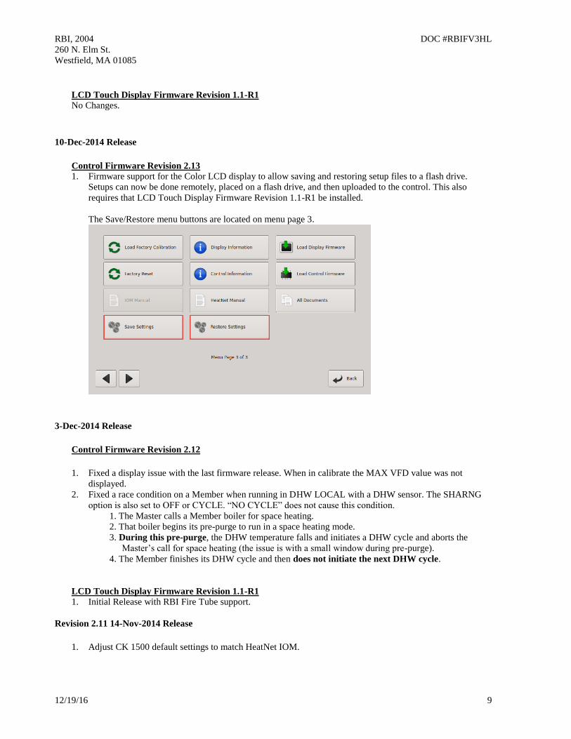
1. Firmware support for the Color LCD display to allow saving and restoring setup files to a flash drive.
Setups can now be done remotely, placed on a flash drive, and then uploaded to the control. This also
requires that LCD Touch Display Firmware Revision 1.1-R1 be installed.
The Save/Restore menu buttons are located on menu page 3.
3-Dec-2014 Release
Control Firmware Revision 2.12
1. Fixed a display issue with the last firmware release. When in calibrate the MAX VFD value was not
displayed.
2. Fixed a race condition on a Member when running in DHW LOCAL with a DHW sensor. The SHARNG
option is also set to OFF or CYCLE. “NO CYCLE” does not cause this condition.
1. The Master calls a Member boiler for space heating.
2. That boiler begins its pre-purge to run in a space heating mode.
3. During this pre-purge, the DHW temperature falls and initiates a DHW cycle and aborts the
Master’s call for space heating (the issue is with a small window during pre-purge).
4. The Member finishes its DHW cycle and then does not initiate the next DHW cycle.
LCD Touch Display Firmware Revision 1.1-R1
1. Initial Release with RBI Fire Tube support.
Revision 2.11 14-Nov-2014 Release
1. Adjust CK 1500 default settings to match HeatNet IOM.
RBI, 2004 DOC #RBIFV3HL
260 N. Elm St.
Westfield, MA 01085
12/19/16 10
Revision 2.10 10-Nov-2014 Release
1. Fixed a flashing message in the STATUS * screen.
2. Fixed a display issue with the DHW modulation % in the DHW graph. The modulation used by the boiler
was correct, but the display % added a scaling offset. This offset was removed. Also, on the DHW screen on
the Master boiler, the % modulation always is for the system DHW Modulation. If the DHW modulation
delay is in effect on the Master or Member, the called for Modulation is displayed.
3. Added the Adaptive Mode to the DHW. This mode was not available in the prior release. Now, the DHW
will use the ADAPTIVE MOD space heating settings when firing DHW boilers.
4. Fixed the DHW Modulation delay to be 60 minutes rather than 4 minutes. This value needs to be set on each
boiler. It is not a global value used by the Master.
5. Added the ability to use the Mod Max value as a limit clamp on DHW boilers. If the ADVANCED SETUP:
MODULAR BOILER SET: DHW HEATING: MOD MAX _ LAST FIRE: RELEASE MOD MAX is set to
YES, then when all boilers are firing, the clamp is released and all boilers are allowed to fire to 100%. If the
RELEASE MOD MAX is set to NO, the clamp will remain in effect regardless if all boilers are firing.
6. Added support for the Firetube CK 1500 boiler.
Revision 2.02-2.04 14-Oct-2014 Release
1. There exists confusion with the DHW BOILER? MIXED setting and the DISTRIBUTED CTRL: MASTER
TYPE: MIXED setting, with the FIRING MODE: MODE: MIXED setting. The setting for DHW and
MASTER TYPE will now be named COMBO, for Combination DHW and Space heating. FIRING MODE:
MODE:MIXED will remain the same.
2. Removed the repeated Fault during retries of the blower. Now, when the blower has failed and a retry is
initiated, HEAT:WAIT is displayed. After 3 attempts the AIR SWITCH (BLOWER) will be displayed along
with the Alarm relay and Fault condition.
3. While in Calibrate, an offset was being applied to the local pump VFD output signal. This offset has been
removed to allow setting up the VFD local pump in calibrate.
Revision 2.01 1-Aug-2014 Release
1. Add support for a Local flow meter. The 2
nd tachometer input on J1 is used to determine flow. Consult
factory for this addition.
2. The Pilot Fan is turned on a few seconds before the Pilot is signaled on by the Honeywell. This is to clean up
a lazy pilot that occurs for about 0.3 seconds.
3. Low OA Set at Modbus address 40009 fails to save properly when written from Modbus/BacNet/LonWorks.
This version corrects this.
Revision 2.00 1-July-2014 Release
1. Full working release for the LCD touch panel display.
RBI, 2004 DOC #RBIFV3HL
260 N. Elm St.
Westfield, MA 01085
12/19/16 11
2. Added the ability to save and restore configuration settings. Access is available in the ADVANCED
SETUP: LOAD DEFAULTS: CONFIG ?
3. Enabled 4-20ma/0-10VDC mode. Mode was not enabled in prior release.
4. When running in DHW Method Master TYPE = Mixed, the boilers firing menus now shows a ‘D’ where a
Domestic Hot Water boiler is firing.
Revision 1.95 -1.99
1. Revise Modbus Address map Figure 40 to include flow registers.
40019 BMSGPMRate 16 bit unsigned 1.0 GPM rate to be loaded by BMS for
calculating how many boilers can run
based on flow.
0-1500 GPM
40020 LimitBoilers 16 bit unsigned 1.0 Write the # of boilers that the BMS allows
to fire. If x boilers are available, x becomes
less than or equal to LimitBoilers.
0-16
2. Revised DHW manual to implement floating sensor on Method 5 and clarified other Methods.
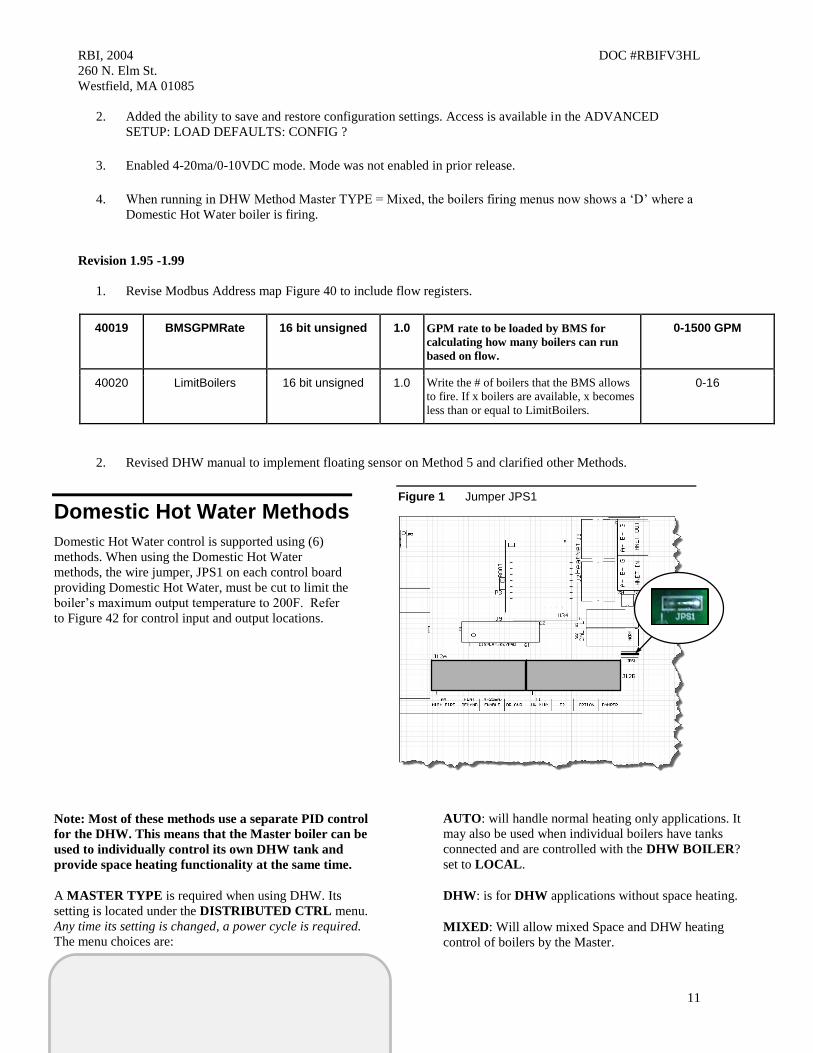
Domestic Hot Water Methods
Domestic Hot Water control is supported using (6)
methods. When using the Domestic Hot Water
methods, the wire jumper, JPS1 on each control board
providing Domestic Hot Water, must be cut to limit the
boiler’s maximum output temperature to 200F. Refer
to Figure 42 for control input and output locations.
Figure 1 Jumper JPS1
Note: Most of these methods use a separate PID control
for the DHW. This means that the Master boiler can be
used to individually control its own DHW tank and
provide space heating functionality at the same time.
A MASTER TYPE is required when using DHW. Its
setting is located under the DISTRIBUTED CTRL menu.
Any time its setting is changed, a power cycle is required.
The menu choices are:
AUTO: will handle normal heating only applications. It
may also be used when individual boilers have tanks
connected and are controlled with the DHW BOILER?
set to LOCAL.
DHW: is for DHW applications without space heating.
MIXED: Will allow mixed Space and DHW heating
control of boilers by the Master.
RBI, 2004 DOC #RBIFV3HL
260 N. Elm St.
Westfield, MA 01085
12/19/16 12
The OR OVR input now functions in many of the
methods as a DHW Heat Demand input (except DHW
Heating Only method), but still retains the original OR OVR
functionality in AUTO, if the DHW menus are not used
(DHW BOILER? NO). If the DISABLE TO CHANGE
message appears, remember to remove the any call for heat
including the OR OVR input.
When the MASTER TYPE is set to MIXED the
MODULAR BOILER SET menu will contain (2) separate
menus for controlling the ADD BOILER DELAY, SHED
BOILER DELAY, MODULATE DELAY, and the MOD
MAX for the system. This allows the independent control
of boilers by the Master for each of the (2) PIDs.
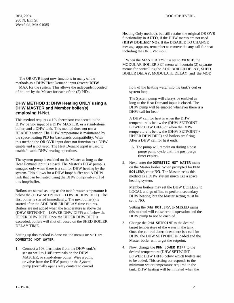
DHW METHOD 1: DHW Heating ONLY using a DHW MASTER and Member boiler(s) employing H-Net.
This method requires a 10k thermistor connected to the
DHW Sensor input of a DHW MASTER, or a stand-alone
boiler, and a DHW tank. This method does not use a
HEADER sensor. The DHW temperature is maintained by
the space heating PID for backwards compatibility. With
this method the OR OVR input does not function as a DHW
enable and is not used. The Heat Demand input is used to
enable/disable DHW heating operations.
The system pump is enabled on the Master as long as the
Heat Demand input is closed. The Master’s DHW pump is
engaged only when there is a call for DHW heating by the
system. This allows for a DHW loop/ buffer and A DHW
tank that can be heated using the DHW pump/valve off of
this loop/buffer.
Boilers are started as long as the tank’s water temperature is
below the (DHW SETPOINT – LOWER DHW DIFF). The
first boiler is started immediately. The next boiler(s) is
started after the ADD BOILER DELAY time expires.
Boilers are not added when the temperature is above the
(DHW SETPOINT – LOWER DHW DIFF) and below the
UPPER DHW DIFF. Once the UPPER DHW DIFF is
exceeded, boilers will shut off based on the SHED BOILER
DELAY TIME.
Setting up this method is done via the menus in: SETUP: DOMESTIC HOT WATER.
1. Connect a 10k thermistor from the DHW tank’s
sensor well to J10B terminals on the DHW
MASTER, or stand-alone boiler. Wire a pump
or valve from the DHW pump or the System
pump (normally open) relay contact to control
flow of the heating water into the tank’s coil or
system loop.
The System pump will always be enabled as
long as the Heat Demand input is closed. The
DHW pump will be enabled whenever there is a
DHW call for heat.
A DHW call for heat is when the DHW
temperature is below the (DHW SETPOINT –
LOWER DHW DIFF) or when the DHW
temperature is below the (DHW SETPOINT +
UPPER DHW DIFF) and boilers are firing.
After a DHW call for heat ends:
A. The pump will remain on during a post
purge pump cycle until the post purge
timer expires.
2. Next, enter the DOMESTIC HOT WATER menu
on the Master boiler. When prompted for DHW BOILER?, enter NO. The Master treats this
method as a DHW system much like a space
heating system.
Member boilers may set the DHW BOILER? to
LOCAL and go offline to perform secondary
DHW heating, but the Master setting must be
set to NO.
Setting the DHW BOILER?, to MIXED using
this method will cause erratic operation and the
DHW pump to not be enabled.
3. Change the DHW SETPOINT to the desired
target temperature of the water in the tank.
Once the control determines there is a call for
DHW, the DHW SETPOINT is loaded and the
Master boiler will target the setpoint.
4. Now, change the DHW LOWER DIFF to the
desired temperature (DHW SETPOINT –
LOWER DHW DIFF) below which boilers are
to be added. This setting corresponds to the
minimum water temperature required in the
tank. DHW heating will be initiated when the
RBI, 2004 DOC #RBIFV3HL
260 N. Elm St.
Westfield, MA 01085
12/19/16 13
DHW tank’s water temperature is below the
temperature (DHW SETPOINT – LOWER
DHW DIFF).
How long the temperature of the tank stays
below the temperature (DHW SETPOINT –
LOWER DHW DIFF)) is used to determine
when boilers are started along with the ADD
BOILER DELAY TIME.
5. Next, change the DHW UPPER DIFF to the
desired temperature (DHW SETPOINT +
UPPER DHW DIFF) above which boilers are to
be shed. This setting is the maximum tank
temperature. Setting the SHED BOILER
DELAY TIME correctly will limit the
maximum tank temperature to the (DHW
SETPOINT + UPPER DHW DIFF). Setting the
SHED BOILER DELAY TIME = 0 will shut
off all boilers immediately once the (DHW
SETPOINT + UPPER DHW DIFF) is
exceeded.
6. Press the DOWN arrow key again to position
the cursor beside the menu item DHW PRIORITY?. Setting this value to YES will turn
OFF the system pump when the DHW mode is
active. Setting this value to NO leaves the
system pump on.
7. Press the DOWN arrow again and the menu
item POST PURGE should appear. This is the
time that the DHW pump relay remains
energized after the DHW SETPOINT has been
satisfied.
A. The pump will remain on during a post
purge pump cycle until the post purge
timer expires.
B. Pump on the Master boiler functions as a
global pump.
8. Scroll down to USE SENSOR? Press the
SELECT key and select YES, then press the
SELECT key again. This will allow the boiler
to control the tank or DHW loop temperature
using the DHW sensor. The upper and lower
differential temperatures will also be loaded.
9. Press the DOWN arrow again and the menu
item: SHARING?, will be displayed.
If this item is set to OFF, only boilers that are
not firing will be checked for runtimes and
fired. Set the SHARING? to OFF.
10. Press the DOWN arrow again and the menu
item LOCAL PUMP OFF: will be displayed.
Set this value to NO. This will leave the local
pump on during a DHW heating cycle
(backwards compatibility). Setting this value to
YES will always keep the local pump off.
The Master’s DHW relay will remain on as
long as there are boiler’s firing and the DHW
temperature is below the (DHW SETPOINT +
UPPER DHW DIFF). Once all boilers are off
and the DHW temp is equal to or above the
(DHW SETPOINT + UPPER DHW DIFF), the
DHW pump will begin its post-purge time. If
during this post-purge time the DHW temp falls
below the (DHW SETPOINT + UPPER DHW
DIFF), the DHW pump will remain on.
Setting this value to YES, will shut the local
pump off during a DHW heating cycle, but will
keep the local pump on for the LOCAL
DELAY: 10s time before shutting off. This
LOCAL DELAY: time can be adjusted in the
next menu item by pressing the down arrow
again.
11. Press the DOWN arrow again and the menu
item PURGE TO THE: will be displayed.
Set this value to TANK. This will purge the
heat from the boiler into the tank or system
loop. This will be done using the DHW pump
after the DHW heating cycle is complete. Set
PURGE TO THE: TANK.
If the PURGE TO THE: is set to SPACE,
once the DHW cycle has completed, the Master
will shut the DHW pump off within a few
seconds. The SPACE setting is to be used only
for mixed space and DHW heating.
12. Set the HYB SENSOR = OFF. This sensor is
selectable for Method 5A only.
Now in the,
ADVANCED SETUP:DISTRIBUTED CTRL: MASTER TYPE select DHW.
NOTE: JPS1 MUST be cut on all boilers
providing DHW.
RBI, 2004 DOC #RBIFV3HL
260 N. Elm St.
Westfield, MA 01085
12/19/16 14
DHW METHOD 2: Combination DHW and Space Heating using a MASTER Boiler and Member boiler(s)
(Master Type: MIXED)
This Method works much the same as DHW METHOD 1,
but also has the ability to provide space heating. The
Master boiler will use two PID controls to simultaneously
maintain the DHW and space heating setpoints. This
method is determined by ADVANCED SETUP:
DISTRIBUTED CTRL: MASTER TYPE: MIXED.
This method utilizes a 10k thermistor connected to the
DHW Sensor input and HEADER sensor input of a
MASTER boiler. Setting up the DHW portion of this
method is done via the menus in: SETUP: DOMESTIC HOT WATER. For information on setting up the space
heating portion of this method, Refer to Heat Demand
Control Method 1 located in the CONTROL METHODS
section.
DHW TANK 2
MEMBER
Main Heating Loop
MASTER
DHW TANK 1
Master Header Sensor
Master DHW Sensor
Parallel Stat Inputs from tanks using RIB relays.
DHW DHW
LOCALLOCAL
HS
HS
HS = Hydraulic separator
RIB
OR OVR
DHW Heating Loop
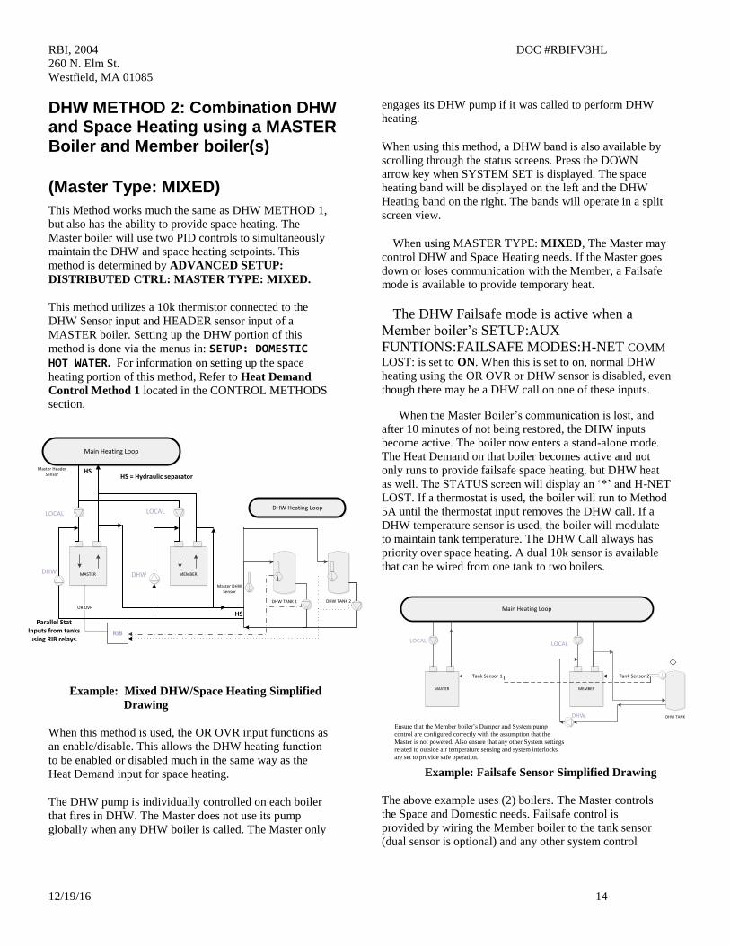
Example: Mixed DHW/Space Heating Simplified
Drawing
When this method is used, the OR OVR input functions as
an enable/disable. This allows the DHW heating function
to be enabled or disabled much in the same way as the
Heat Demand input for space heating.
The DHW pump is individually controlled on each boiler
that fires in DHW. The Master does not use its pump
globally when any DHW boiler is called. The Master only
engages its DHW pump if it was called to perform DHW
heating.
When using this method, a DHW band is also available by
scrolling through the status screens. Press the DOWN
arrow key when SYSTEM SET is displayed. The space
heating band will be displayed on the left and the DHW
Heating band on the right. The bands will operate in a split
screen view.
When using MASTER TYPE: MIXED, The Master may
control DHW and Space Heating needs. If the Master goes
down or loses communication with the Member, a Failsafe
mode is available to provide temporary heat.
The DHW Failsafe mode is active when a
Member boiler’s SETUP:AUX
FUNTIONS:FAILSAFE MODES:H-NET COMM
LOST: is set to ON. When this is set to on, normal DHW
heating using the OR OVR or DHW sensor is disabled, even
though there may be a DHW call on one of these inputs.
When the Master Boiler’s communication is lost, and
after 10 minutes of not being restored, the DHW inputs
become active. The boiler now enters a stand-alone mode.
The Heat Demand on that boiler becomes active and not
only runs to provide failsafe space heating, but DHW heat
as well. The STATUS screen will display an ‘*’ and H-NET
LOST. If a thermostat is used, the boiler will run to Method
5A until the thermostat input removes the DHW call. If a
DHW temperature sensor is used, the boiler will modulate
to maintain tank temperature. The DHW Call always has
priority over space heating. A dual 10k sensor is available
that can be wired from one tank to two boilers.
DHW TANK
MEMBER
Tank Sensor 2
MASTER
Tank Sensor 1
Main Heating Loop
LOCAL LOCAL
DHW
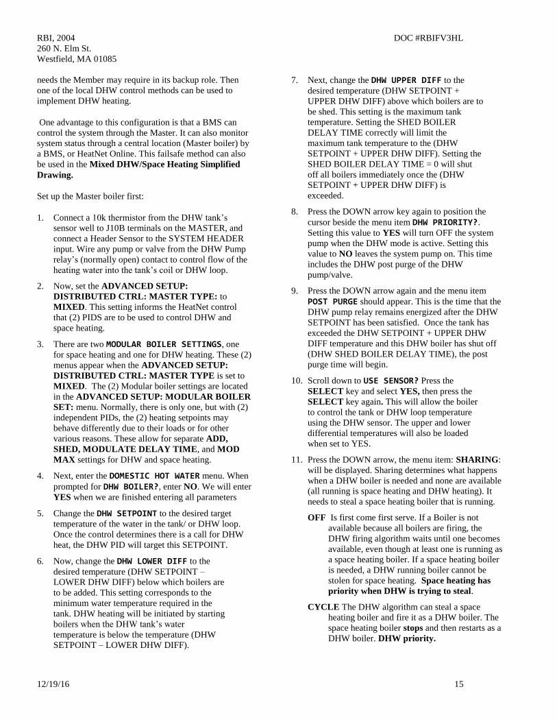
Ensure that the Member boiler’s Damper and System pump
control are configured correctly with the assumption that the
Master is not powered. Also ensure that any other System settings
related to outside air temperature sensing and system interlocks
are set to provide safe operation.
Example: Failsafe Sensor Simplified Drawing
The above example uses (2) boilers. The Master controls
the Space and Domestic needs. Failsafe control is
provided by wiring the Member boiler to the tank sensor
(dual sensor is optional) and any other system control
RBI, 2004 DOC #RBIFV3HL
260 N. Elm St.
Westfield, MA 01085
12/19/16 15
needs the Member may require in its backup role. Then
one of the local DHW control methods can be used to
implement DHW heating.
One advantage to this configuration is that a BMS can
control the system through the Master. It can also monitor
system status through a central location (Master boiler) by
a BMS, or HeatNet Online. This failsafe method can also
be used in the Mixed DHW/Space Heating Simplified
Drawing.
Set up the Master boiler first:
1. Connect a 10k thermistor from the DHW tank’s
sensor well to J10B terminals on the MASTER, and
connect a Header Sensor to the SYSTEM HEADER
input. Wire any pump or valve from the DHW Pump
relay’s (normally open) contact to control flow of the
heating water into the tank’s coil or DHW loop.
2. Now, set the ADVANCED SETUP:
DISTRIBUTED CTRL: MASTER TYPE: to
MIXED. This setting informs the HeatNet control
that (2) PIDS are to be used to control DHW and
space heating.
3. There are two MODULAR BOILER SETTINGS, one
for space heating and one for DHW heating. These (2)
menus appear when the ADVANCED SETUP:
DISTRIBUTED CTRL: MASTER TYPE is set to
MIXED. The (2) Modular boiler settings are located
in the ADVANCED SETUP: MODULAR BOILER
SET: menu. Normally, there is only one, but with (2)
independent PIDs, the (2) heating setpoints may
behave differently due to their loads or for other
various reasons. These allow for separate ADD,
SHED, MODULATE DELAY TIME, and MOD
MAX settings for DHW and space heating.
4. Next, enter the DOMESTIC HOT WATER menu. When
prompted for DHW BOILER?, enter NO. We will enter
YES when we are finished entering all parameters
5. Change the DHW SETPOINT to the desired target
temperature of the water in the tank/ or DHW loop.
Once the control determines there is a call for DHW
heat, the DHW PID will target this SETPOINT.
6. Now, change the DHW LOWER DIFF to the
desired temperature (DHW SETPOINT –
LOWER DHW DIFF) below which boilers are
to be added. This setting corresponds to the
minimum water temperature required in the
tank. DHW heating will be initiated by starting
boilers when the DHW tank’s water
temperature is below the temperature (DHW
SETPOINT – LOWER DHW DIFF).
7. Next, change the DHW UPPER DIFF to the
desired temperature (DHW SETPOINT +
UPPER DHW DIFF) above which boilers are to
be shed. This setting is the maximum tank
temperature. Setting the SHED BOILER
DELAY TIME correctly will limit the
maximum tank temperature to the (DHW
SETPOINT + UPPER DHW DIFF). Setting the
SHED BOILER DELAY TIME = 0 will shut
off all boilers immediately once the (DHW
SETPOINT + UPPER DHW DIFF) is
exceeded.
8. Press the DOWN arrow key again to position the
cursor beside the menu item DHW PRIORITY?.
Setting this value to YES will turn OFF the system
pump when the DHW mode is active. Setting this
value to NO leaves the system pump on. This time
includes the DHW post purge of the DHW
pump/valve.
9. Press the DOWN arrow again and the menu item
POST PURGE should appear. This is the time that the
DHW pump relay remains energized after the DHW
SETPOINT has been satisfied. Once the tank has
exceeded the DHW SETPOINT + UPPER DHW
DIFF temperature and this DHW boiler has shut off
(DHW SHED BOILER DELAY TIME), the post
purge time will begin.
10. Scroll down to USE SENSOR? Press the
SELECT key and select YES, then press the
SELECT key again. This will allow the boiler
to control the tank or DHW loop temperature
using the DHW sensor. The upper and lower
differential temperatures will also be loaded
when set to YES.
11. Press the DOWN arrow, the menu item: SHARING:
will be displayed. Sharing determines what happens
when a DHW boiler is needed and none are available
(all running is space heating and DHW heating). It
needs to steal a space heating boiler that is running.
OFF Is first come first serve. If a Boiler is not
available because all boilers are firing, the
DHW firing algorithm waits until one becomes
available, even though at least one is running as
a space heating boiler. If a space heating boiler
is needed, a DHW running boiler cannot be
stolen for space heating. Space heating has
priority when DHW is trying to steal.
CYCLE The DHW algorithm can steal a space
heating boiler and fire it as a DHW boiler. The
space heating boiler stops and then restarts as a
DHW boiler. DHW priority.
RBI, 2004 DOC #RBIFV3HL
260 N. Elm St.
Westfield, MA 01085
12/19/16 16
NO CYCLE The DHW algorithm can steal a boiler
that is already running as a space heating boiler.
Instead of shutting down the space heating
boiler, it does a hot swap, engaging the DHW
pump and leaving the local pump running or
shutting it off. Use this in conjunction with the
LOCAL PUMP OFF: and the LOCAL
DELAY: settings. DHW priority.
12. Press the DOWN arrow, the menu item: LOCAL
PUMP OFF: is displayed. When a DHW heating
cycle begins, what to do with the local pump/valve is
determined:
NO The local pump/valve will remain running during
DHW heating.
YES The local pump will shut off with a delay
determined by LOCAL DELAY: seconds. This
allows the DHW pump/valve to prove before
shutting off the local pump.
Piping of the system will determine which setting
to use.
13. Press the DOWN arrow, the menu item: PURGE TO
THE: is displayed. After a DHW cycle completes, the
pump/valve can be selected to either purge to the
TANK, or to the SPACE for the duration of the post
purge time. This selection can use the space to dump
the heat from the boiler and not overheat the DHW
tank/load.
14. Set the HYB SENSOR = OFF. This sensor is
selectable for Method 5A only.
15. Finally, Press the UP arrow until the menu: DHW BOILER? is displayed.. If JPS1 has not been cut, a
message will appear instructing to do so. Once this is
done, the MASTER boiler will control the
temperature in the tank using as many boilers as it has
available on H-Net along with the space heating
needs. The boilers must be piped appropriately for
this method to function correctly.
Now set up the Member boiler(s).
DHW BOILER? Set to MIXED on MEMBER
boilers, only the MASTER boiler.
DHW SETPOINT This does not need to be set on
MEMBER boilers, only the MASTER boiler.
LOWER DHW DIFF This does not need to be on
MEMBER boilers, only the MASTER boiler.
UPPER DHW DIFF This does not need to be set on
MEMBER boilers, only the MASTER boiler.
DHW PRIORITY This does not need to be set on
MEMBER boilers, only the MASTER boiler.
POST PURGE This needs to be set on all boilers. All
boilers control their respective DHW
pump/valve when they are called to perform
DHW heating.
SHARING This can be set on any boiler and will
how boilers will cycle on/off when they are
called to perform DHW Heating.
LOCAL PUMP OFF This can be set on any boiler to
determine how the local pump/valve behaves
when called to perform DHW heating.
PURGE TO THE: This does not need to be set on
MEMBER boilers, only the MASTER boiler.
HYB SENSOR: = OFF. This sensor is
selectable for Method 5A only.
NOTE: JPS1 MUST be cut on all boilers
providing DHW. Cutting JPS1 limits to
maximum temperatures to 200F.
DHW METHOD 3: DHW Heating using a Header Sensor Input
This method will control a tank temperature when the tank
temperature setpoint needs to be maintained for extended
periods with minimal cycling. Multiple boilers can be used
via the H-Net, as this method employs the same PID
algorithm as for space heating. ADVANCED SETUP:
DISTRIBUTED CTRL: MASTER TYPE: AUTO.
1. JPS1 must be cut on all boilers providing
DHW to ensure the maximum output
temperature of all boilers is limited to 200F for
DHW operation.
This Method is very similar to the DHW only
method, but:
A. The display will not indicate that it is a
DHW heating boiler.
B. The DHW Heating band will also not
be displayed.
C. The heating band will use the space
heating band and not the UPPER and
LOWER DHW heating band limits.
RBI, 2004 DOC #RBIFV3HL
260 N. Elm St.
Westfield, MA 01085
12/19/16 17
D. DHW settings are not used.
E. Set the ADVANCED SETUP:
DISTRIBUTED CTRL: MASTER
TYPE: to AUTO.
F. This method is for backwards
compatibility.
2. Use the Heat Demand Control Method 1
located in the CONTROL METHODS section
on page 22. Instead of placing the Header
sensor in the Header pipe, place it in a well, in
the tank, or a DHW loop.
The temperature at which boilers are staged
ON, and then OFF is controlled by the
SETUP:BOILERS:HEAT BAND differential.
This can be understood by referring to the
INTRODUCTION section on the MASTER in
the beginning of this manual.
This differential has the added effect of heating
the tank above the tank’s setpoint temperature.
If the tank setpoint is set to 140F and the heat
band is set to 10F, then the tank temperature
will rise to 145F before the first boiler turns off
(setpoint =140F +/- heat band/2). With (2)
boilers running, the SHED BOILER DELAY
time could add to the tank temperature. So, to
ensure that all boilers are shut off at the upper
point of the heat band, set the SHED BOILER
DELAY time to 0 or other small value. This
will effectively turn off all boilers at the upper
heat band point of: (example) 145F.
Now, there is one more thing to consider, the
pump’s post purge time. Dumping the heat from
all boilers (that were running) using a pump
post purge cycle will have an effect on the
tank’s water temperature. Consider this when
establishing the local pump’s POST PURGE
TIME.
3. Connect the Local Pump relay contact on J13 to
enable the DHW pump. Set its post purge time
to dump the boiler’s heat into the tank when the
boiler shuts off. Be aware that this may heat
the tank above the setpoint’s upper heat
band temperature.
4. Enable the system by placing the
LOCAL/REMOTE switch on the Master to the
LOCAL position.
DHW METHOD 4: Space Heating with DHW Override of Setpoint on Master
This method is for controlling DHW utilizing a tank
thermostat connected to a Master boiler. This method
requires a thermostat input to the OR OVR. When the
thermostat contact closes across the input OR OVR
(J12A .7 & .8), the control will sense this closure and
override the space heating setpoint with the DHW
setpoint. ADVANCED SETUP: DISTRIBUTED
CTRL: MASTER TYPE: AUTO.
This method is for backwards compatibility.
In this mode, the boiler will fire to the DHW
setpoint. The settings for space heating will be used
except for the addition of controlling the DHW
pump/valve.
13. Wire the dry contact from the thermostat on the
tank to the input on J12A terminal 7 & 8. Also,
at this time wire any pump or valve from the
DHW Pump relay (normally open) contact (J13
terminals 9, 10) to control flow of the heating
water into the tank’s coil.
14. Enter the DOMESTIC HOT WATER
MENU. When prompted for DHW BOILER?,
enter NO.
15. DHW SETPOINT The setpoint should reflect the
temperature desired in the heating loop when a tank is
calling for DHW heat.
16. LOWER DHW DIFF This is not used.
17. UPPER DHW DIFF This is not used.
18. DHW PRIORITY Setting this value to YES will
turn OFF the system pump when the DHW setpoint
override mode is active. Setting this value to NO
leaves the system pump on. This active period
includes the post purge of the DHW pump/valve.
19. Select the menu item POST PURGE. This is the time
that the DHW pump relay remains energized after the
DHW thermostat has been satisfied. Once the tank
has opened it’s thermostat, the system/local setpoint
will be reloaded and the post purge time will begin.
20. Select the menu item: LOCAL PUMP OFF: When a
DHW heating cycle begins, what to do with the local
pump/valve is determined:
RBI, 2004 DOC #RBIFV3HL
260 N. Elm St.
Westfield, MA 01085
12/19/16 18
NO The local pump/valve will remain running during
DHW heating.
YES The local pump will shut off with a delay
determined by LOCAL DELAY: seconds. This
allows the DHW pump/valve to prove before
shutting off the local pump.
Piping of the system will determine which setting
to use.
21. Select the menu item: PURGE TO THE. After a
DHW cycle completes, the pump/valve can be
selected to either purge to the TANK, or to the
SPACE for the duration of the post purge time. This
selection can use the space to dump the heat from the
boiler and not overheat the DHW tank/load.
22. Set the HYB SENSOR = OFF. This sensor is
selectable for Method 5A only.
Follow the same steps as used to program DHW
Heating using a Header Sensor INPUT. USE
SENSOR?, select NO.
DHW METHOD 5: DHW of a Local Boiler’s Tank.
Method 5A using a 10k Type II tank sensor. This method is used to provide combination space heating
and DHW heating. The boiler may be stand alone or in a
HeatNet configuration. It is meant to fire an individual
boiler in a DHW heating priority mode when that boiler’s
local tank temperature has a call for DHW heat (tank
sensor’s temperature drops below the DHW Setpoint +
Lower Diff). The boiler will stop space heating (if
running) and switch to DHW heating. The DHW
pump/valve will be engaged and the water temperature in
the tank will be maintained by the boiler at the DHW
setpoint. Once the tank temperature exceeds the Setpoint +
Upper Diff temperature, DHW heating will stop and the
pump/valve’s post purge will start.
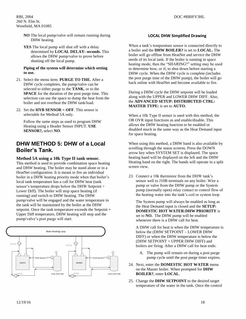
LOCAL DHW TANK
MEMBER
Tank Sensor
LOCAL DHW TANK
MASTER
Tank Sensor
Main Heating Loop
LOCAL LOCAL
DHW DHW
LOCAL DHW Simplified Drawing
When a tank’s temperature sensor is connected directly to
a boiler and the DHW BOILER? is set to LOCAL. The
boiler will go offline from HeatNet and service the DHW
needs of its local tank. If the boiler is running in space
heating mode, then the “SHARING?” setting may be used
to determine how, or if, to shut down before starting a
DHW cycle. When the DHW cycle is complete (includes
the post purge time of the DHW pump), the boiler will go
back online with HeatNet and become available to fire.
During a DHW cycle the DHW setpoint will be loaded
along with the UPPER and LOWER DHW DIFF. Also,
the ADVANCED SETUP: DISTRIBUTED CTRL:
MASTER TYPE: is set to AUTO.
When a 10k Type II sensor is used with this method, the
OR OVR input functions as and enable/disable. This
allows the DHW heating function to be enabled or
disabled much in the same way as the Heat Demand input
for space heating.
When using this method, a DHW band is also available by
scrolling through the status screens. Press the DOWN
arrow key when SYSTEM SET is displayed. The space
heating band will be displayed on the left and the DHW
Heating band on the right. The bands will operate in a split
screen view.
23. Connect a 10k thermistor from the DHW tank’s
sensor well to J10B terminals on any boiler. Wire a
pump or valve from the DHW pump or the System
pump (normally open) relay contact to control flow of
the heating water into the tank’s coil or system loop.
The System pump will always be enabled as long as
the Heat Demand input is closed and the SETUP:
DOMESTIC HOT WATER:DHW PRIORITY is
set to NO. The DHW pump will be enabled
whenever there is a DHW call for heat.
A DHW call for heat is when the DHW temperature is
below the (DHW SETPOINT – LOWER DHW
DIFF) or when the DHW temperature is below the
(DHW SETPOINT + UPPER DHW DIFF) and
boilers are firing. After a DHW call for heat ends:
A. The pump will remain on during a post purge
pump cycle until the post purge timer expires.
24. Next, enter the DOMESTIC HOT WATER menu
on the Master boiler. When prompted for DHW
BOILER?, enter LOCAL.
25. Change the DHW SETPOINT to the desired target
temperature of the water in the tank. Once the control

RBI, 2004 DOC #RBIFV3HL
260 N. Elm St.
Westfield, MA 01085
12/19/16 19
determines there is a call for DHW, the DHW
SETPOINT is loaded and the boiler will target the
setpoint.
26. Now, change the DHW LOWER DIFF to the
desired temperature (DHW SETPOINT – LOWER
DHW DIFF) below which boilers are to be added.
This setting corresponds to the minimum water
temperature required in the tank. DHW heating will
be initiated when the DHW tank’s water temperature
is below the temperature (DHW SETPOINT –
LOWER DHW DIFF).
How long the temperature of the tank stays below the
temperature (DHW SETPOINT – LOWER DHW
DIFF)) is used to determine when boilers are started
along with the ADD BOILER DELAY TIME.
27. Next, change the DHW UPPER DIFF to the desired
temperature (DHW SETPOINT + UPPER DHW
DIFF) above which boilers are to be shed. This setting
is the maximum tank temperature. Setting the SHED
BOILER DELAY TIME correctly will limit the
maximum tank temperature to the (DHW SETPOINT
+ UPPER DHW DIFF). Setting the SHED BOILER
DELAY TIME = 0 will shut off all boilers
immediately once the (DHW SETPOINT + UPPER
DHW DIFF) is exceeded.
28. Press the DOWN arrow key again to position
the cursor beside the menu item DHW
PRIORITY?. Setting this value to YES will
turn OFF the system pump when the DHW
mode is active (when the DHW pump is on).
Setting this value to NO leaves the system
pump on.
29. Press the DOWN arrow again and the menu
item POST PURGE should appear. This is the
time that the DHW pump relay remains
energized after the DHW SETPOINT has been
satisfied.
A. The pump will remain on during a post
purge pump cycle until the post purge
timer expires.
30. Scroll down to USE SENSOR? Press the
SELECT key and select YES, then press the
SELECT key again. This will allow the boiler
to control the local tank or DHW loop
temperature using the DHW sensor. The upper
and lower differential temperatures will also be
loaded.
31. Press the DOWN arrow again and the menu
item: SHARING?, will be displayed.
Set this item is to OFF or CYLE if the boiler is
currently running in space heating and needs to
be shut down before starting up in DHW.
If SHARING? is set to NO CYCLE a hot
swap will occur. A hot swap is when the boiler
is running in space heating mode and does not
need to be shut down. The DHW pump will be
energized without the boiler stopping. Once the
DHW cycle has completed, the boiler will stop
and wait to be called again for either space
heating or DHW heating. A shutdown always
occurs after a DHW cycle completes.
32. Press the DOWN arrow again and the menu
item LOCAL PUMP OFF: will be displayed.
Set this value to NO. This will leave the local
pump on during a DHW heating cycle
(backwards compatibility). Setting this value to
YES will always keep the local pump off.
Setting this value to YES, will shut the local
pump off during a DHW heating cycle, but will
keep the local pump on for the LOCAL
DELAY: 10s time before shutting off. This
LOCAL DELAY: time can be adjusted in the
next menu item by pressing the down arrow
again.
33. Press the DOWN arrow again and the menu
item PURGE TO THE: will be displayed.
Set this value to TANK. This will purge the
heat from the boiler into the tank or system
loop. This will be done using the DHW pump
after the DHW heating cycle is complete. Set
PURGE TO THE: TANK.
If the PURGE TO THE: is set to SPACE,
once the DHW cycle has completed, the Master
will shut the DHW pump off within a few
seconds. The SPACE setting is to be used only
for mixed space and DHW heating.
HYB SENSOR = OFF
ADVANCED SETUP:DISTRIBUTED CTRL: MASTER TYPE select DHW.
NOTE: JPS1 MUST be cut on all boilers
providing DHW.
Method 5B using a Thermostat & Sensor. Method 5(B) can also be used in a hybrid mode on
Member boilers with a thermostat connected to the OR
OVR input. This will enable DHW heating, and be used
instead of having the 10k sensor’s temperature detect
when DHW heating is needed, but will use a selectable
sensor instead to maintain setpoint.

RBI, 2004 DOC #RBIFV3HL
260 N. Elm St.
Westfield, MA 01085
12/19/16 20
DHW TANK
MEMBER
Thermostat
DHW TANK
MASTER
Thermistor Sensor
Main Heating Loop
LOCAL
LOCAL
DHW DHW
= Hybrid mode sensor locations.(Selectible)
Simplified Drawing When the OR OVR input sees the thermostat close, the
DHW pump/valve will be engaged and remain
energized as long as the OR OVR input sees that the
thermostat is closed. The DHW setpoint along with the
DHW heating band will then be loaded. A steady
temperature will now be maintained using the HYB
SENSOR setting in the DHW menu. This sensor will
control the water temperature at the sensor’s location,
enabling or disabling the boiler as needed until the OR
OVR input sees the thermostat open. Once the
thermostat opens, the DHW pump post purge will begin.
The difference between setting up the 5A method vs 5B
method is the “USE SENSOR?” setting. 5A requires
that the “USE SENSOR?” setting be set to YES, and
the 5B “USE SENSOR?” setting be set to NO. The
HYB SENSOR setting must also be set in the 5B mode
to the sensor where temperature needs to be maintained.
It must be set to OFF in the 5A mode.
Method 5A USE SENSOR? = YES HYB SENSOR: OFF
Method 5B
USE SENSOR? = NO HYB SENSOR: SUPPLY, DHW,
RETURN
Each sensor selection/location has its advantages.
Selecting the:
Supply sensor will limit the temperature/firing rate of
the boiler, but may not be sufficient for continuous
demand or speed in heating the tank. It is already
available, so no additional sensor is needed.
Return sensor will allow the boiler to run its supply
temperature up quickly, but may bounce off of the
operating limit band. This would heat the tank in the
shortest time, but may overheat the tank. It is already
available, so no additional sensor is needed.
DHW sensor will allow the placement anywhere needed
to maintain that locations temperature. This is an
additional sensor that needs to be acquired.
A thermostat can be placed in a tank and connected to
the OR OVR input. (On Member boilers only, The
Master uses OR OVR already with DHW METHOD 4),
When the thermostat contact closes across the input OR
OVR (J12A .7 & .8) on a Member boiler, the control
will sense this closure and disconnect itself from
HeatNet.
DHW METHOD 6: DHW using Direct Control
If the control’s 4-20mA input is set to HIGH
PRIORITY the 4-20mA signal, once brought
above the 4-20mA starting current can be used to
override any other Heat Demand and direct
modulate the boiler.
This can be set in menu: ADVANCED
SETUP:4-20mA INPUT. It allows a member
boiler to be taken offline and directly modulated
by an external control. If the Master is using it for heating and the 4-20mA is set to
HIGH PRIORITY, an external control can now output a 4-
20mA signal which will take over the boiler’s fire rate and
override all other heating demand inputs. The external control
would also need to open any valves/ or pumps This is typically
used for DHW control.
RBI, 2004 DOC #RBIFV3HL
260 N. Elm St.
Westfield, MA 01085
12/19/16 21
Revision 1.92 8-APRIL-2014 Original Release
Revision 1.93-1.94 8-APRIL-2014 Original Release
1. The 4-20mA setpoint input not working properly. Input was disabled with the initial release. With this release it
now functions properly.
2. The Flow proving timers were erratic when using DHW mode with a DHW pump and keeping the Local pump
off. Retries also only allowed 10 seconds to prove rather than the local pump adjustable proving time.
Revision 1.11 5- OCT-2013 Pre-Release
1. Added additional time when waiting for a response from large flash drives. Some large flash drives tested (16
gigabyte and up), exceeded 5 seconds in response to a command sent requesting contents of the firmware
directory. If this firmware release cannot be loaded using a large flash drive, a smaller/faster flash drive may
be required.
Revision 1.10 2- OCT-2013 Pre-Release
1. Added some status checking to a running member boiler that will notify the Master of status. i.e. DHW sensor
shorted and Calibration switch. This allows the boiler to be taken offline by the Master boiler when running in
DHW modes.
2. Added the ability of the Master to work as a DHW MASTER only ‘ADVANCED SETUP:DISTRIBUTED
CTRL:MASTER TYPE: -> DHW’ without the use of a header sensor. This change was for backwards
compatibility.
3. When using a DHW sensor in DHW modes, the OR OVR input becomes the Enable/Disable for the DHW.
4. Added the ability to change the way that a DHW local call-for-heat overrides a running boiler. The
“SETUP:DOMESTIC HOT WATER:MIXED DHW-SPACE:SHARING:” can now be set to CYCLE,
NO_CYCLE and OFF for local control of DHW on a Member boiler.
Revision 1.09 23- SEPT-2013 Pre-Release
1. Fixed some display artifacts when using DHW modes.
2. Changed the ability to enable and disable DHW modes while the system is running. The HEAT DEMAND and
the OR OVR inputs must be disabled prior to changing these menu settings. Prior to this release, indeterminate
action would occur in DHW operation.
3. Added a note when using the Master boiler in DHW mode. If the Master boiler is set to ADVANCED
SETUP:DISTRIBUTED CTRL:MASTER TYPE: ->MIXED, the setting SETUP:DOMESTIC HOT
WATER:DHW BOILER?:->LOCAL is not valid. A message will be displayed in the SETUP:DOMESTIC
HOT WATER: if it is changed.
Two ways to operate the Master as a DHW boiler:
RBI, 2004 DOC #RBIFV3HL
260 N. Elm St.
Westfield, MA 01085
12/19/16 22
When the Master is operated as a “ADVANCED SETUP:DISTRIBUTED CTRL:MASTER TYPE: -> MIXED”
Master it uses the temperature sensor assigned to its DHW input. The DHW temperature sensor becomes common
to all boilers operating as “SETUP:DOMESTIC HOT WATER:DHW BOILER?:->MIXED” In order to use the
Master as a DHW boiler in the MIXED Master mode, the “ SETUP:DOMESTIC HOT WATER:DHW BOILER?:-
> ” must be set to MIXED on the MASTER. The OA OVR input is then used to enable/disable DHW operation
just as the HEAT DEMAND input.
If the ADVANCED SETUP:DISTRIBUTED CTRL:MASTER TYPE: -> is set to AUTO, the Master
“SETUP:DOMESTIC HOT WATER:DHW BOILER?:->” can then be set to LOCAL and the Master can then be
taken offline to perform DHW heating independently from space heating to control a local tank. The DHW sensor
will only be used to monitor its local tank. The Master behaves like a Member boiler operating in DHW except that
the Master will maintain and operate on (2) PID loops (space & DHW heating).
Revision 1.08 17- SEPT-2013 Release
1. Fixed a protection mode condition when the Local VFD 0-10v modulation signal used to modulate a pump
(J4.1 & J4.5) equaled or exceeded 100%. When this condition occurred, the PWM modulation would drop to
0.
During protection mode, and when the boiler is limiting the fire rate (input), the modulation control signal will
remain at the called for rate and will not follow the limiting modulation’s firing rate. The primary purpose for
this is to maintain sufficient flow through the boiler when the boiler may be operating within the operating
limit band.
2. Increased the efficiency of the (5) communications ports when all (5) ports are connected and being used at
high transfer rates. The (5) ports include: HeatNet, Modbus, HeatNet Online (Ethernet), USB, and TBA
intelligent display.
3. Fixed a condition when using the VFD local pump output signal on J4.1 and J4.5. The VFD pump control
signal would only go as high as 8VDC when in Calibrate. This has been corrected to allow 0-10VDC output.
4. Beta release candidate for Space Heating and DHW heating mixed mode still in effect. Added the ability
for the Master boiler to control itself and the system as a space heating boiler(s) and only itself in DHW mode
with a local tank. In this mode, The Master does not control DHW Member boilers. It controls space heating
only and let’s each boiler control its own local tank.
SETTING UP AN ALTERNATIVE INDIVIDUAL DHW CONTROL:

RBI, 2004 DOC #RBIFV3HL
260 N. Elm St.
Westfield, MA 01085
12/19/16 23
DHW TANK
MEMBER
Tank Sensor
DHW TANK
MASTER
Tank Sensor
Main Heating Loop
LOCAL LOCAL
DHW DHW
Simplified Drawing
In the above example each DHW tank is controlled individually by a boiler and space heating is provided by both
boilers. The Master boiler will be used to provide space heating to the system by using both boilers and DHW heat
to its local tank. The Member boiler will provide space heating when called by the Master and DHW heat when
requested by its local tank.
When a boiler is called by the tank, it will go off-line from the HeatNet Master and control its local DHW tank
temperature. The OV OVR input or a DHW temperature sensor connected to the boiler is required to make the
request.
To set this method up requires the Master boiler to have its own localized loop. So it would need to set the
ADVANCED SETUP:DISTRIBUTED CTRL:MASTER TYPE: ->AUTO and the SETUP:DOMESTIC HOT
WATER:DHW BOILER?:->LOCAL. This will allow it to control itself for Space heat and DHW heat. This
configuration would require a Header sensor and a DHW tank sensor. In this configuration, the Master’s tank
should not use a stat to control its call for heat.
The Member boilers that are configured to locally control their own tanks would set their menu
SETUP:DOMESTIC HOT WATER:DHW BOILER?:->LOCAL. This would allow the boiler to operate on the
tank using a sensor or stat input. The Member would not send back DHW availability to the Master and therefore
allow the Master to control the boiler for space heating only.
Revision 1.06 26- AUG-2013 Pre-Release
1. Beta release candidate for Space Heating and DHW heating mixed mode.
Mixed DHW Mode
This firmware release for HeatNet V3 platform introduces a mode which allows DHW boilers and Space heating
boilers to be shared. In order to do this, (2) PID control loops are used
RBI, 2004 DOC #RBIFV3HL
260 N. Elm St.
Westfield, MA 01085
12/19/16 24
Prior releases of HeatNet allowed (3) DHW control methods: dedicating the system to DHW, allowing DHW and
Space heating where only one could be used at a time, or taking a boiler off-line to perform DHW Heating while
leaving the remaining boilers to heat the space.
One limitation of the prior releases was that the HeatNet Master could not perform concurrent DHW and space
heating and the Master could not be taken off-line to perform DHW heating. This limitation in a (2) boiler system
created a condition where the Member could be taken off-line to heat a tank, but the Master could not. This resulted
in the Master remaining in standby.
Another limitation was that the local pump would always remain running when in DHW heating.
This additional method allows simultaneous control of two heating loops and overcomes the limitations. The
intention is to provide for a Space heating system loop and a DHW heating loop. The prior method of taking a
boiler off-line for DHW can also be employed with this method. This allows for more configurations and the ability
to allow the Master boiler to heat a tank independently from the Member (When the Member has been pulled off-
line for DHW heating using prior methods).
The second DHW heating loop can be as small as one boiler and one tank or many boilers with many tanks.
If DHW and Space heating boilers are to be mixed and controlled by the Master boiler, the menus need to be set up
properly. Also, it is important to pipe the boilers appropriately. The pump/valve and changeover settings that have
been provided are very flexible for ease in setting up system configurations.
Two new screens and several menu items have been added to allow flexibility of the system. Many of the menus
are not visible until ADVANCED SETUP:DISTRIBUTED CTRL:MASTER TYPE->MIXED is set on the Master
boiler.
The new menu items are:
ADVANCED SETUP:DISTRIBUTED CTRL:MASTER TYPE: -> AUTO, DHW, HEATING, MIXED.
AUTO is the normal method of operation as in prior releases.
DHW is for DHW heating only. A DHW sensor is required with no Header sensor
HEATING is for Space heating only, the AUTO setting performs the same. Requires Header sensor.
MIXED is for mixed DHW and Space heating where the Master controls both. Requires a Header and DHW
sensor.
ADVANCED SETUP: MODULAR BOILER SET: -> SPACE HEATING, DHW HEATING
SPACE HEATING is the ADD BOILER, SHED BOILER, MODULATE DELAY TIME, MOD MAX menus
DHW HEATING is the same as SPACE HEATING, but specific when boilers are running as DHW
SETUP:DOMESTIC HOT WATER: DHW BOILER? NO, LOCAL, MIXED
NO is the setting when the boiler is not configured to perform DHW heating.
LOCAL is for local DHW heating without the Master being able to call it. It’s own DHW sensor or OV OVR input
can be used. Boiler will be taken off-line from HeatNet to perform DHW heating.
MIXED is used by the boiler to let the Master know it can perform DHW heating under control of the Master
boiler. It may also be taken off-line to provide LOCAL heating.
SETUP:DOMESTIC HOT WATER:MIXED DHW-SPACE:DHW SHARING -> OFF, NO CYCLE, CYCLE

RBI, 2004 DOC #RBIFV3HL
260 N. Elm St.
Westfield, MA 01085
12/19/16 25
NO CYCLE allows the boiler to perform as a space or DHW heating boiler. DHW always has priority and will
override (steal) a space heating boiler that is running when none are available to perform DHW heating. When this
happens, the boiler will not shut down, but keep running during the change from space heating to DHW (Hot
Swap). Once the DHW cycle completes, the boiler will shut down and wait to be called for space heating again.
CAUTION: If used in a low temperature heat pump system a forced shutdown may need to occur. TBD
Flow proving contacts and valve proving contacts need to be taken into account here. If the LOCAL PUMP OFF
setting is set to YES, ensure enough time is given in LOCAL DELAY to re-establish flow in the path to the tank
before shutting off the local pump/valve.
CYCLE allows the boiler to perform as a space or DHW heating boiler. DHW always has priority and will
override (steal) a space heating boiler that is running when none are available to perform DHW heating. When this
happens, the boiler will shut down and exit the space heating mode. The boiler will then re-start as a DHW heating
boiler. Once the DHW cycle completes, the boiler will shut down and wait to be called for space heating again.
OFF allows the boiler to perform as a space or DHW heating boiler, but will not allow a space heating boiler that is
running to be overridden if none are available. The system acts on a “First Come First Serve” basis. The heating
system should be sized appropriately to minimize the chances of not providing sufficient DHW heat during cold
weather.
SETUP:DOMESTIC HOT WATER:MIXED DHW-SPACE:LOCAL PUMP OFF -> YES, NO
YES will shut off the local pump/valve when DHW heating is in effect. If the boiler is running in space heating
mode, the LOCAL DELAY will be in effect before the local pump/valve shuts off.
NO both the local and the DHW pump/valve will be enabled during DHW heating.
SETUP:DOMESTIC HOT WATER:MIXED DHW-SPACE:LOCAL DELAY: x seconds
X seconds is the time in seconds that the local pump/valve will remain on after the DHW pump/valve is enabled
before shutting off. This is part of the changeover process when the boiler was running in space heating mode and
now needs to provide DHW heating.
SETUP:DOMESTIC HOT WATER:MIXED DHW-SPACE:PURGE TO THE: TANK, SPACE
TANK will keep the DHW pump/valve enabled for the DHW POST PURGE time thus purging the boilers heat
into the tank.
SPACE will turn off the DHW pump after 5 seconds and enable the local pump/valve when a DHW heating cycle
completes. This allows dumping the remaining heat from the boiler into the heating space (dump zone).
Status Screen:
In order to show the two simultaneous PIDs (Space Heating and DHW) a split screen has been added. It can be
accessed from the main RUN screen by pressing the Down key. The Left side of the band will display the Space
heating band. The right side will display the DHW heating band.
In the split screen with DHW and Space heating, the DHW: run% will display mDHW: run% when the Master
boiler is running in mixed mode as a DHW boiler.
A second screen has been added primarily to display the START and STOP timers when the DHW heating has a
call for heat. This screen can be accessed by pressing the Down key another time while in the split screen. The
START and STOP timers here work the same as the heating START and STOP timers.
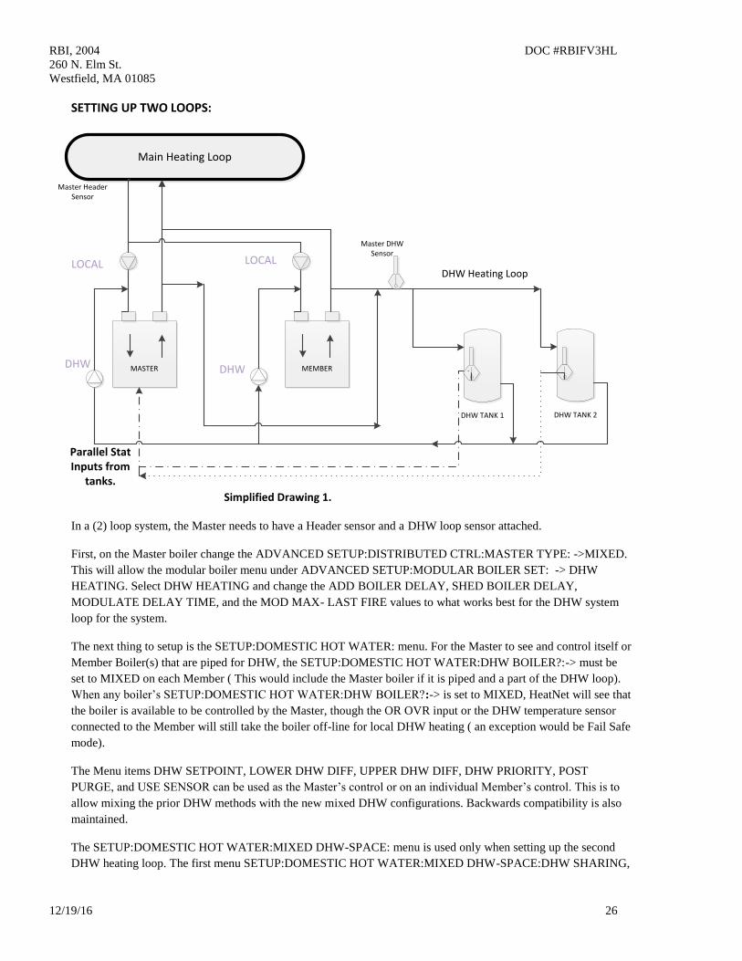
RBI, 2004 DOC #RBIFV3HL
260 N. Elm St.
Westfield, MA 01085
12/19/16 26
SETTING UP TWO LOOPS:
DHW TANK 2
MEMBER
Main Heating Loop
MASTER
DHW TANK 1
Master Header Sensor
Master DHW Sensor
DHW Heating Loop
Parallel Stat Inputs from
tanks.
DHW DHW
LOCALLOCAL
Simplified Drawing 1.
In a (2) loop system, the Master needs to have a Header sensor and a DHW loop sensor attached.
First, on the Master boiler change the ADVANCED SETUP:DISTRIBUTED CTRL:MASTER TYPE: ->MIXED.
This will allow the modular boiler menu under ADVANCED SETUP:MODULAR BOILER SET: -> DHW
HEATING. Select DHW HEATING and change the ADD BOILER DELAY, SHED BOILER DELAY,
MODULATE DELAY TIME, and the MOD MAX- LAST FIRE values to what works best for the DHW system
loop for the system.
The next thing to setup is the SETUP:DOMESTIC HOT WATER: menu. For the Master to see and control itself or
Member Boiler(s) that are piped for DHW, the SETUP:DOMESTIC HOT WATER:DHW BOILER?:-> must be
set to MIXED on each Member ( This would include the Master boiler if it is piped and a part of the DHW loop).
When any boiler’s SETUP:DOMESTIC HOT WATER:DHW BOILER?:-> is set to MIXED, HeatNet will see that
the boiler is available to be controlled by the Master, though the OR OVR input or the DHW temperature sensor
connected to the Member will still take the boiler off-line for local DHW heating ( an exception would be Fail Safe
mode).
The Menu items DHW SETPOINT, LOWER DHW DIFF, UPPER DHW DIFF, DHW PRIORITY, POST
PURGE, and USE SENSOR can be used as the Master’s control or on an individual Member’s control. This is to
allow mixing the prior DHW methods with the new mixed DHW configurations. Backwards compatibility is also
maintained.
The SETUP:DOMESTIC HOT WATER:MIXED DHW-SPACE: menu is used only when setting up the second
DHW heating loop. The first menu SETUP:DOMESTIC HOT WATER:MIXED DHW-SPACE:DHW SHARING,
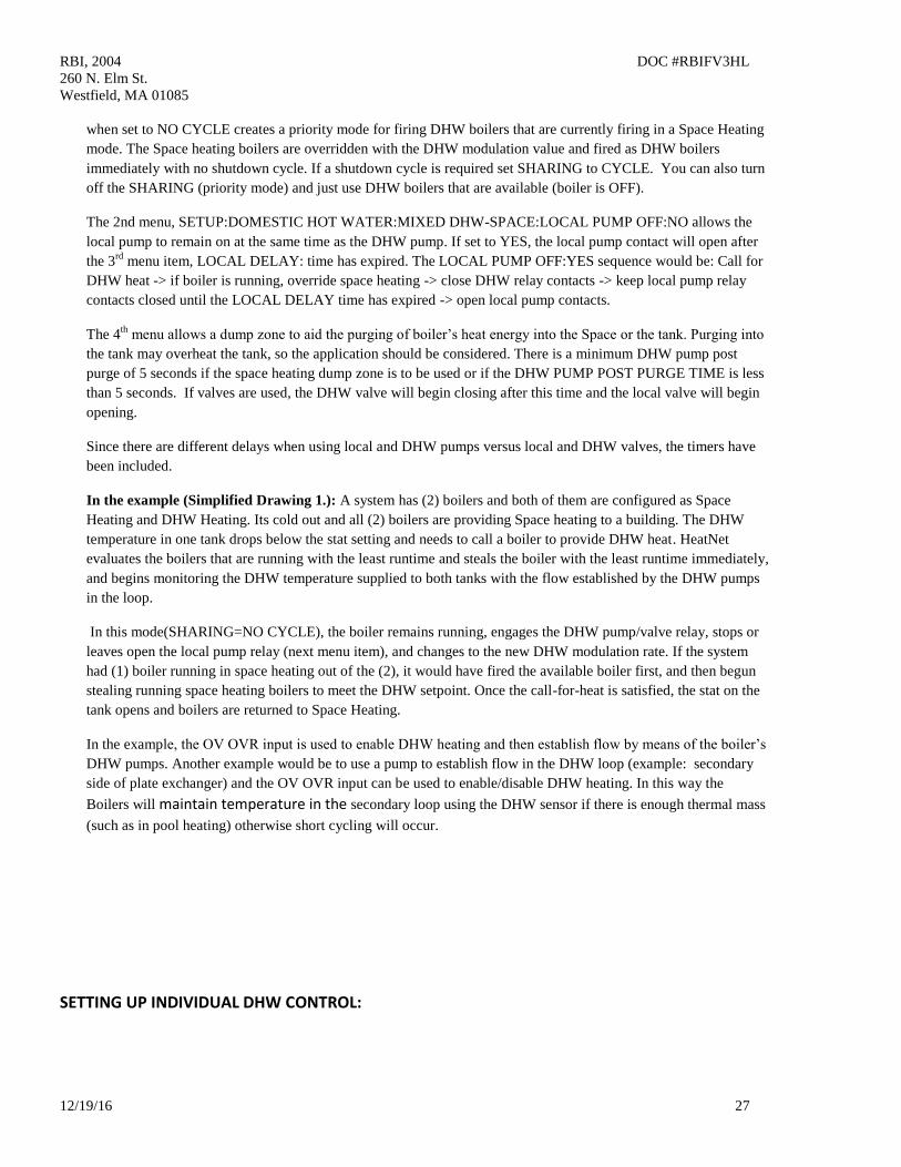
RBI, 2004 DOC #RBIFV3HL
260 N. Elm St.
Westfield, MA 01085
12/19/16 27
when set to NO CYCLE creates a priority mode for firing DHW boilers that are currently firing in a Space Heating
mode. The Space heating boilers are overridden with the DHW modulation value and fired as DHW boilers
immediately with no shutdown cycle. If a shutdown cycle is required set SHARING to CYCLE. You can also turn
off the SHARING (priority mode) and just use DHW boilers that are available (boiler is OFF).
The 2nd menu, SETUP:DOMESTIC HOT WATER:MIXED DHW-SPACE:LOCAL PUMP OFF:NO allows the
local pump to remain on at the same time as the DHW pump. If set to YES, the local pump contact will open after
the 3rd
menu item, LOCAL DELAY: time has expired. The LOCAL PUMP OFF:YES sequence would be: Call for
DHW heat -> if boiler is running, override space heating -> close DHW relay contacts -> keep local pump relay
contacts closed until the LOCAL DELAY time has expired -> open local pump contacts.
The 4th
menu allows a dump zone to aid the purging of boiler’s heat energy into the Space or the tank. Purging into
the tank may overheat the tank, so the application should be considered. There is a minimum DHW pump post
purge of 5 seconds if the space heating dump zone is to be used or if the DHW PUMP POST PURGE TIME is less
than 5 seconds. If valves are used, the DHW valve will begin closing after this time and the local valve will begin
opening.
Since there are different delays when using local and DHW pumps versus local and DHW valves, the timers have
been included.
In the example (Simplified Drawing 1.): A system has (2) boilers and both of them are configured as Space
Heating and DHW Heating. Its cold out and all (2) boilers are providing Space heating to a building. The DHW
temperature in one tank drops below the stat setting and needs to call a boiler to provide DHW heat. HeatNet
evaluates the boilers that are running with the least runtime and steals the boiler with the least runtime immediately,
and begins monitoring the DHW temperature supplied to both tanks with the flow established by the DHW pumps
in the loop.
In this mode(SHARING=NO CYCLE), the boiler remains running, engages the DHW pump/valve relay, stops or
leaves open the local pump relay (next menu item), and changes to the new DHW modulation rate. If the system
had (1) boiler running in space heating out of the (2), it would have fired the available boiler first, and then begun
stealing running space heating boilers to meet the DHW setpoint. Once the call-for-heat is satisfied, the stat on the
tank opens and boilers are returned to Space Heating.
In the example, the OV OVR input is used to enable DHW heating and then establish flow by means of the boiler’s
DHW pumps. Another example would be to use a pump to establish flow in the DHW loop (example: secondary
side of plate exchanger) and the OV OVR input can be used to enable/disable DHW heating. In this way the
Boilers will maintain temperature in the secondary loop using the DHW sensor if there is enough thermal mass
(such as in pool heating) otherwise short cycling will occur.
SETTING UP INDIVIDUAL DHW CONTROL:
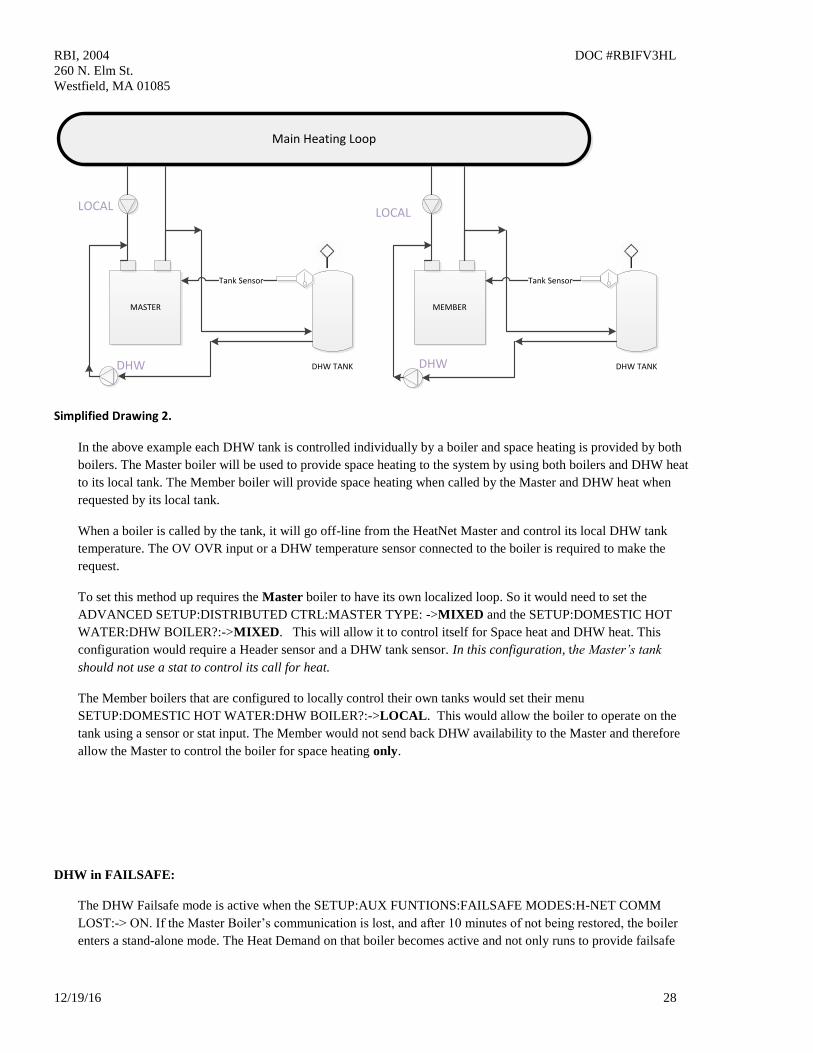
RBI, 2004 DOC #RBIFV3HL
260 N. Elm St.
Westfield, MA 01085
12/19/16 28
DHW TANK
MEMBER
Tank Sensor
DHW TANK
MASTER
Tank Sensor
Main Heating Loop
LOCAL LOCAL
DHW DHW
Simplified Drawing 2.
In the above example each DHW tank is controlled individually by a boiler and space heating is provided by both
boilers. The Master boiler will be used to provide space heating to the system by using both boilers and DHW heat
to its local tank. The Member boiler will provide space heating when called by the Master and DHW heat when
requested by its local tank.
When a boiler is called by the tank, it will go off-line from the HeatNet Master and control its local DHW tank
temperature. The OV OVR input or a DHW temperature sensor connected to the boiler is required to make the
request.
To set this method up requires the Master boiler to have its own localized loop. So it would need to set the
ADVANCED SETUP:DISTRIBUTED CTRL:MASTER TYPE: ->MIXED and the SETUP:DOMESTIC HOT
WATER:DHW BOILER?:->MIXED. This will allow it to control itself for Space heat and DHW heat. This
configuration would require a Header sensor and a DHW tank sensor. In this configuration, the Master’s tank
should not use a stat to control its call for heat.
The Member boilers that are configured to locally control their own tanks would set their menu
SETUP:DOMESTIC HOT WATER:DHW BOILER?:->LOCAL. This would allow the boiler to operate on the
tank using a sensor or stat input. The Member would not send back DHW availability to the Master and therefore
allow the Master to control the boiler for space heating only.
DHW in FAILSAFE:
The DHW Failsafe mode is active when the SETUP:AUX FUNTIONS:FAILSAFE MODES:H-NET COMM
LOST:-> ON. If the Master Boiler’s communication is lost, and after 10 minutes of not being restored, the boiler
enters a stand-alone mode. The Heat Demand on that boiler becomes active and not only runs to provide failsafe

RBI, 2004 DOC #RBIFV3HL
260 N. Elm St.
Westfield, MA 01085
12/19/16 29
space heating, but DHW heat as well. The STATUS screen will display an ‘*’ and H-NET LOST. If a stat is used,
the boiler will run to 100% until the stat removes the DHW call. If a temperature sensor is used, the boiler will
modulate to maintain tank temperature. The DHW Call always has priority over space heating.
The Failsafe boiler needs to either have a stat input from a DHW tank or a temperature sensor connected to a tank.
When these sensors are connected normally, they would override any call to the boiler by the Master (when in
SETUP:DOMESTIC HOT WATER:DHW BOILER?:-> MIXED mode) and enter DHW heating mode. With the
Failsafe active, this function is inhibited and the Failsafe boiler only responds to these inputs with the loss of the
Master’s communication.
Revision 1.05 28-Feb-2013 Pre-Release
1. Added a BTU load measurement when using a flow meter with a System Return sensor. This value can be
viewed under the FLOW window. The BTU value is relative to the accuracy of the sensors and is only
available as an estimate of the BTU load.
The BTU load value may also be accessed through Modbus read registers 30242 (upper 16 bit word) & 30243
(lower 16 bit word). These two words will need to be combined in order to get the BTU load value.
When using the BMS GPM register the BTU values are only calculated to a whole GPM since the BMS GPM
register currently does not support floating point numbers.
2. Replaced the 4-20 mA setpoint settings when using 0-10V input. The 0-10 V input may now be set using
voltage settings rather than current.
3. Added (2) log entry types for debugging faults.
A. If the Main Valve signal is lost from the Ignition Control while the boiler is running a log entry, LOST MAIN
VALVE with the modulation value being sent to the blower at the time of loss. Example: LOST MAIN
VALVE 40
B. If the Blower signal is lost from the Ignition Control while the boiler is running a log entry, LOST BLOWER
with the modulation value being sent to the blower at the time of loss. Example: LOST BLOWER 27
4. Normalized the 0-10 volt control signal for direct fire applications. Such that: 1 volt will track linearly by 10%.
So, 1v=10%, 2v=20%, 3v=30%, 4v=40%... The control signal will still be limited by the turndown and the 4-
20mA INPUT menu.
5. Removed the ability to silence the alarm with the push button. Alarm silencing is now done by pressing the
BACK and ENTER keys at the same time. The input that was used for the ALARM SILENCE will now be
dedicated to a stack sensor.
6. Added the auto detection of a Stack Sensor. If the Stack Sensor is present, a warning will occur at 325F and
greater, and an Alarm will occur at 350F and greater. During the Warning and Alarm conditions the boiler will
be limited to half the rate of fire requested. The only difference between the two is that the Alarm will close
the Alarm relay.
The Stack sensor should be a 1k ohm platinum type sensor. Part # 0040-1300. Currently, a 10k version is not
supported due to the maximum temperature of the flue.
Revision 1.04 20-Feb-2013 Pre-Release
RBI, 2004 DOC #RBIFV3HL
260 N. Elm St.
Westfield, MA 01085
12/19/16 30
This revision addresses some bug fixes from the prior pre-release firmware and gives more control in overcoming
issues with variable flow systems.
1. Fixed an issue that happens when a Modbus Setpoint is written and the outdoor reset
is active. The (2) setpoints would override each other randomly.
With this release, if a higher level setpoint control is lost, the next level setpoint control is used until the
System Setpoint is loaded. The setpoints are prioritized in the following order:
1. 0-10V, 4-20Ma setpoint Control
2. BMS, Modbus Setpoint
3. Outdoor Reset Setpoint
4. System Setpoint
Any Setbacks that are active are then applied.
2. Added the ability of a Building Management System (BMS) to limit the # of HeatNet boilers allowed to fire.
With this addition; when a system has a fixed amount of boilers that HeatNet reports are available, the BMS
can now limit the # of boilers that can fire. The BMS can write the GPM value it has for flow, or directly write
a register with how many boilers HeatNet can control. If the BMS GPM flow feature is active, the direct
control becomes inactive.
This change is in response to requests to limit HeatNet’s control of adding boilers when the system flow changes.
In variable flow systems, when the system flow is reduced, any boiler(s) that is/are running may go into a high
delta temperature across the boiler. When this occurs, the boiler(s) will enter a high delta T protection mode and
drop to half of the rate called for. At this time, the Master may not be able to achieve setpoint due to the reduced
output with the running boiler(s). The Master will then call on more boilers to achieve setpoint, but at the same
time splitting the already reduced flow through the boiler(s) it has running. The flow can now be so reduced that
the boiler(s) trip their operating limits or even their high limits.
Note: using these features can limit HeatNet’s ability to maintain setpoint.
1.) Flow Limited Control: This method helps HeatNet to limit the # of boilers firing based on the System Flow in
GPM. In variable flow systems, this will limit HeatNet’s ability to add new boilers when insufficient flow is
available. The # of boilers allowed to fire is determined by:
# of HeatNet boilers that can fire = BMS GPM Set Rate/ LOWEST FLOW
To activate this flow limited feature for use with a BMS:
a. Set ADVANCED SETUP: FLOWMETER: FLOWMETER? YES
b. Set ADVANCED SETUP: FLOWMETER: GLYCOL MIX ? % , Currently, any mix over 10% de-rates
the flow by 30% (rule of thumb method). Example: if the LOWEST FLOW = 50 GPM, HeatNet will
calculate a New Lowest Flow required to be 65 GPM. The LOWEST FLOW does not need to be changed,
but is calculated to 65 GPM and that value is used by HeatNet.
c. Set ADVANCED SETUP: FLOWMETER: INPUT TYPE to BMS.
d. Set ADVANCED SETUP: FLOWMETER: SET PARAMETERS?
Enter LOWEST FLOW: (The automatic value loaded will equal the lowest flow required for this boiler (it
is adjustable). It should be = to the lowest flow of the largest boiler in the system).
e. The HIGHEST FLOW & FLOW FACTOR are currently not used with this release. Once flow meter
manufacturers have been determined, new firmware will become available.
f. Write to address BMS GPM register 40019 with a valid flow (0 -1500 GPM).
g. If a new GPM value is not written within 10 minutes, this feature will be deactivated until a new flow
value is written. Ensure periodic updates of the flow register are done within 10 minute intervals.
RBI, 2004 DOC #RBIFV3HL
260 N. Elm St.
Westfield, MA 01085
12/19/16 31
h. To check if HeatNet is in a flow limited state, read the boiler status 4 register starting at address 30160 for
the Master Boiler; if Status 4 bit (12) is set, it indicates that the HeatNet control is running with limited
boilers due to insufficient flow derived from the GPM value.
2.) Boilers Limited Control: This feature allows the BMS to directly change the amount of boilers that HeatNet
can control.
To Activate the Boiler limited feature:
a. Read Modbus address 30241 to see how many boilers HeatNet has available to fire. MODBUS
AVAILABLE BOILERS register.
b. Determine how many boilers the BMS system will require.
c. Write to address BMS LIMIT BOILERS register 40020 with the # of boilers HeatNet is allowed to control
(0 - 16).
d. If a new boiler # value is not written within 10 minutes, this feature will be deactivated until a new
boiler # is written. Ensure periodic updates of the flow register are done within 10 minute intervals.
e. To check if HeatNet is in a BMS limited state, read the boiler status 4 register starting at address 30160 for
the Master Boiler; if Status 4 bit (13) is set, it indicates that the HeatNet control is running with limited
boilers due to the BMS system specifying BMS LIMIT BOILERS being less than the available boilers.
4. Added the ability of a Flow Meter to control the # of HeatNet boilers allowed to fire. With this addition;
HeatNet will look at the # of boilers it has available, and the amount of system flow to determine how
many of boilers it can fire. As an Example: An Onicon F-1210 Flow Meter provides simultaneous 0-10V
and 4-20mA outputs, so if the BMS system is using (1) output, the other may be used by HeatNet.
To activate this flow limited feature for use with an Onicon Flow Meter F-1210:
a. Set ADVANCED SETUP: FLOWMETER: FLOWMETER? YES
f. Set ADVANCED SETUP: FLOWMETER: GLYCOL MIX ? % , Currently, any mix over 10% de-rates
the flow by 30% (rule of thumb method). Example: if the LOWEST FLOW = 50 GPM, HeatNet will
calculate a New Lowest Flow required to be 65 GPM. The LOWEST FLOW does not need to be changed,
but is calculated to 65 GPM and that value is used by HeatNet.
b. Set ADVANCED SETUP: FLOWMETER: INPUT TYPE to mA 2 or VOLTS 2 depending on whether a 4-
20 milliamp or 0-10 volt signal is used. The connection should be made from the Flow Meter to analog
input 4-20 mA (2).
c. Select ADVANCED SETUP: FLOWMETER: SET PARAMETERS?
Enter LOWEST FLOW: (The automatic value loaded will equal the lowest flow required for this boiler (it
is adjustable). It should be equal to the lowest flow of the largest boiler in the system).
d. Set the ADVANCED SETUP: FLOWMETER: FULL SCALE value to the full scale reading on the
calibration card that came with the flow meter.
e. The HIGHEST FLOW & FLOW FACTOR currently are not used with this release.
f. These settings will use the equations:
4-20 mA: Measured GPM = (signal/16) * FULL SCALE flow
0-10 Volt: Measured GPM = (signal/10) * FULL SCALE flow
These settings may work with other flow meters (consult their respective manuals).
RBI, 2004 DOC #RBIFV3HL
260 N. Elm St.
Westfield, MA 01085
12/19/16 32
Revision 1.03 18-Jan-2013 Pre-Release
1. Replaced the DHW differential temperature setting with an upper and lower control band limit (UPPER
DHW DIFF & LOWER DHW DIFF). Instead of using just a differential temperature below the setpoint,
the differential temperature now consists of a lower band limit and an upper band limit which can be set
independently. This allows a DHW tank temperature to be maintained using a PID rather than the boiler
shutting off at setpoint.
The LOWER DHW DIFF brings on DHW heating when the DHW tank temperature falls below the (DHW
SETPOINT - LOWER DHW DIFF). The boiler then maintains temperature until the (DHW SETPOINT +
UPPER DHW DIFF) is exceeded. The UPPER DHW DIFF must be set properly to prevent overheating of
the tank. The UPPER DHW DIFF + DHW SETPOINT should be set to the tank temperature required. In
this way the tank temperature - UPPER DHW DIFF will be maintained while a continuous demand is
present. When the continuous demand ends, the tank will be left at the (DHW SETPOINT + UPPER DHW
DIFF) temperature.