RBC Aerospace Bearing Products Plain · PDF fileTABLE OF CONTENTS For more information visit...
107
unique design solutions to complex problems The Global Leader in Aerospace Bearings Spherical Bearings Rod End Bearings Journal Bearings Links and Assemblies www.rbcbearings.com Plain Bearings Plain Bearings PLAIN BEARINGS
Transcript of RBC Aerospace Bearing Products Plain · PDF fileTABLE OF CONTENTS For more information visit...

unique design solutionsto complex problems
The Global Leader in Aerospace Bearings
Spherical Bearings
Rod End Bearings
Journal Bearings
Links and Assemblies
www.rbcbearings.com
Plain Bearings
Plain Bearings
RBC A
EROSPA
CE BEA
RING
SPLA
IN BEA
RING
Sw
ww
.rbcbearings.com
RBC Aerospace Bearing Products
Spherical Bearings• MS approved to AS81820
(formerly MIL-B-81820) • Boeing and Airbus approved • Self-lubricating • Metal-to-Metal • Loader slots • High temperature • Low coefficient of friction • Special configurations and materials
Rod End Bearings• MS approved to AS81935
(formerly MIL-B-81935)• Boeing and Airbus approved • Self-lubricating • Metal-to-Metal • Loader slots • High temperature • Low coefficient of friction • Special configurations and materials
Track Rollers• MS approved to AS39901
(formerly MIL-B-3990)• Boeing and Airbus approved • ATF single row and ATL double row • Sealed with lube holes and grooves • Heavy duty cross-sections• Advanced AeroCres® materials available
Cargo Roller Bearings• Boeing approved • Features precision ground, semi-ground,
and unground ball bearings• Offered in caged and full complement
configurations
Ball Bearing Rod Ends• MS approved to AS6039
(formerly MIL-B-6039) • Boeing approved • Various shank configurations • Low coefficient of friction• Advanced AeroCres® materials available
Cam Followers• MS approved to AS39901
(formerly MIL-B-3990)• Advanced AeroCres® materials available• Maximum corrosion resistance• Superior lubricants and seals to reduce
maintenance
Journal Bearings• MS approved to AS81934
(formerly MIL-B-81934)• Boeing and Airbus approved • Plain and flanged • Self-lubricating • High temperature • High loads • Available in inch and metric sizes
Thin Section Ball Bearings• Standard cross-sections to one inch • Stainless steel and other materials are
available • Sizes to 40 inches • Seals available on all sizes and
standard cross-sections• Super duplex configurations
Load Slot Bearings• Spherical and rod end designs• Superior ball-to-race conformity• Reduced maintenance cost• Variety of race materials available• Boeing approved
Double Row Hourglass Bearings• Boeing approved• High Radial and Axial Load Ratings• Low Torque• Integral Swage Grooves Available• Pyrowear®, Cronidur30®, 52100, 9310 or 440C
Specials• Many specialty bearings, custom-
designed and configured for diverse aerospace applications
• Capability for advanced aerospace specialty corrosion resistant and high temperature materials
Airframe Control Ball Bearings• MS approved to AS7949
(formerly MIL-B-7949)• Boeing and Airbus approved • Single and double row • Radial, self-aligning, and pulley series • 52100 Cad plated and 440C stainless
RBC Bearings Incorporated has been producing bearings in the USA since 1919.RBC offers a full line of aerospace bearings, including unique custom configurations.
www.rbcbearings.com
© 2008, 2011, 2016 RBC Bearings Incorporated. All rights reserved.
This document contains a general overview of the products and features described herein. It is solely for informational purposes, does not represent a warranty of theinformation contained herein, and is not to be construed as an offer to sell or a solicitation to buy. Contact RBC Bearings for detailed information suitable to your specificapplications. RBC Bearings reserves the right to modify its products and related product information at any time without prior notice.
Some of the products listed herein may be covered by one or more issued and pending U.S. or foreign patents. Contact RBC Bearings for product specific information.
Innovation. Commitment. Quality.
RBC-ACRE REV. 10/16
PB_FBcvrs_8-29-16_Layout 1 8/29/16 8:35 PM Page 1
TABL
E OF
CON
TENT
S
For more information visit our web site at rbcbearings.com
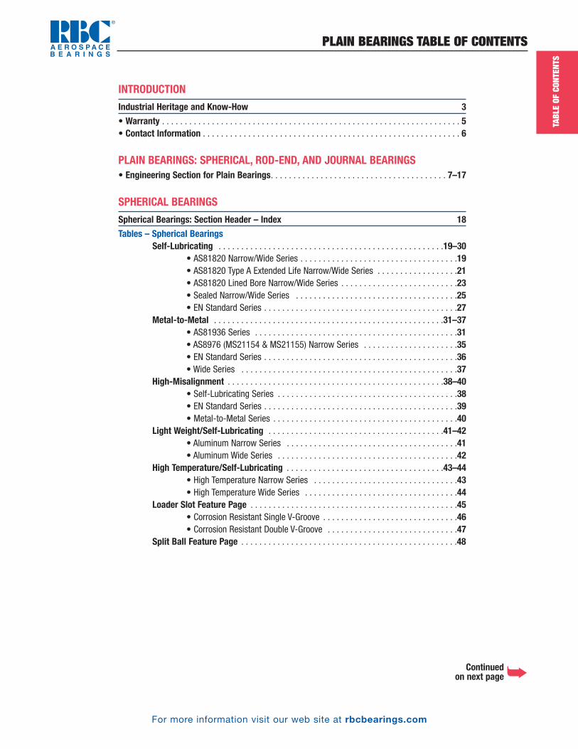
PLAIN BEARINGS TABLE OF CONTENTS
INTRODUCTION
Industrial Heritage and Know-How 3
• Warranty . . . . . . . . . . . . . . . . . . . . . . . . . . . . . . . . . . . . . . . . . . . . . . . . . . . . . . . . . . . . . . . . . . 5• Contact Information . . . . . . . . . . . . . . . . . . . . . . . . . . . . . . . . . . . . . . . . . . . . . . . . . . . . . . . . . 6
PLAIN BEARINGS: SPHERICAL, ROD-END, AND JOURNAL BEARINGS• Engineering Section for Plain Bearings. . . . . . . . . . . . . . . . . . . . . . . . . . . . . . . . . . . . . . . 7–17
SPHERICAL BEARINGS
Spherical Bearings: Section Header – Index 18
Tables – Spherical BearingsSelf-Lubricating . . . . . . . . . . . . . . . . . . . . . . . . . . . . . . . . . . . . . . . . . . . . . . . . . .19–30
• AS81820 Narrow/Wide Series . . . . . . . . . . . . . . . . . . . . . . . . . . . . . . . . . . .19• AS81820 Type A Extended Life Narrow/Wide Series . . . . . . . . . . . . . . . . . .21• AS81820 Lined Bore Narrow/Wide Series . . . . . . . . . . . . . . . . . . . . . . . . . .23• Sealed Narrow/Wide Series . . . . . . . . . . . . . . . . . . . . . . . . . . . . . . . . . . . .25• EN Standard Series . . . . . . . . . . . . . . . . . . . . . . . . . . . . . . . . . . . . . . . . . . .27
Metal-to-Metal . . . . . . . . . . . . . . . . . . . . . . . . . . . . . . . . . . . . . . . . . . . . . . . . . . .31–37• AS81936 Series . . . . . . . . . . . . . . . . . . . . . . . . . . . . . . . . . . . . . . . . . . . . .31• AS8976 (MS21154 & MS21155) Narrow Series . . . . . . . . . . . . . . . . . . . . .35• EN Standard Series . . . . . . . . . . . . . . . . . . . . . . . . . . . . . . . . . . . . . . . . . . .36• Wide Series . . . . . . . . . . . . . . . . . . . . . . . . . . . . . . . . . . . . . . . . . . . . . . . .37
High-Misalignment . . . . . . . . . . . . . . . . . . . . . . . . . . . . . . . . . . . . . . . . . . . . . . . .38–40• Self-Lubricating Series . . . . . . . . . . . . . . . . . . . . . . . . . . . . . . . . . . . . . . . .38• EN Standard Series . . . . . . . . . . . . . . . . . . . . . . . . . . . . . . . . . . . . . . . . . . .39• Metal-to-Metal Series . . . . . . . . . . . . . . . . . . . . . . . . . . . . . . . . . . . . . . . . .40
Light Weight/Self-Lubricating . . . . . . . . . . . . . . . . . . . . . . . . . . . . . . . . . . . . . . .41–42• Aluminum Narrow Series . . . . . . . . . . . . . . . . . . . . . . . . . . . . . . . . . . . . . .41• Aluminum Wide Series . . . . . . . . . . . . . . . . . . . . . . . . . . . . . . . . . . . . . . . .42
High Temperature/Self-Lubricating . . . . . . . . . . . . . . . . . . . . . . . . . . . . . . . . . . .43–44• High Temperature Narrow Series . . . . . . . . . . . . . . . . . . . . . . . . . . . . . . . .43• High Temperature Wide Series . . . . . . . . . . . . . . . . . . . . . . . . . . . . . . . . . .44
Loader Slot Feature Page . . . . . . . . . . . . . . . . . . . . . . . . . . . . . . . . . . . . . . . . . . . . . .45• Corrosion Resistant Single V-Groove . . . . . . . . . . . . . . . . . . . . . . . . . . . . . .46• Corrosion Resistant Double V-Groove . . . . . . . . . . . . . . . . . . . . . . . . . . . . .47
Split Ball Feature Page . . . . . . . . . . . . . . . . . . . . . . . . . . . . . . . . . . . . . . . . . . . . . . . .48
Continued on next page�
PB_Index_8-29-16_Pln_Index.qxd 8/29/16 8:36 PM Page 1
TABL
E OF
CON
TENT
S
For more information visit our web site at rbcbearings.com
PLAIN BEARINGS TABLE OF CONTENTS
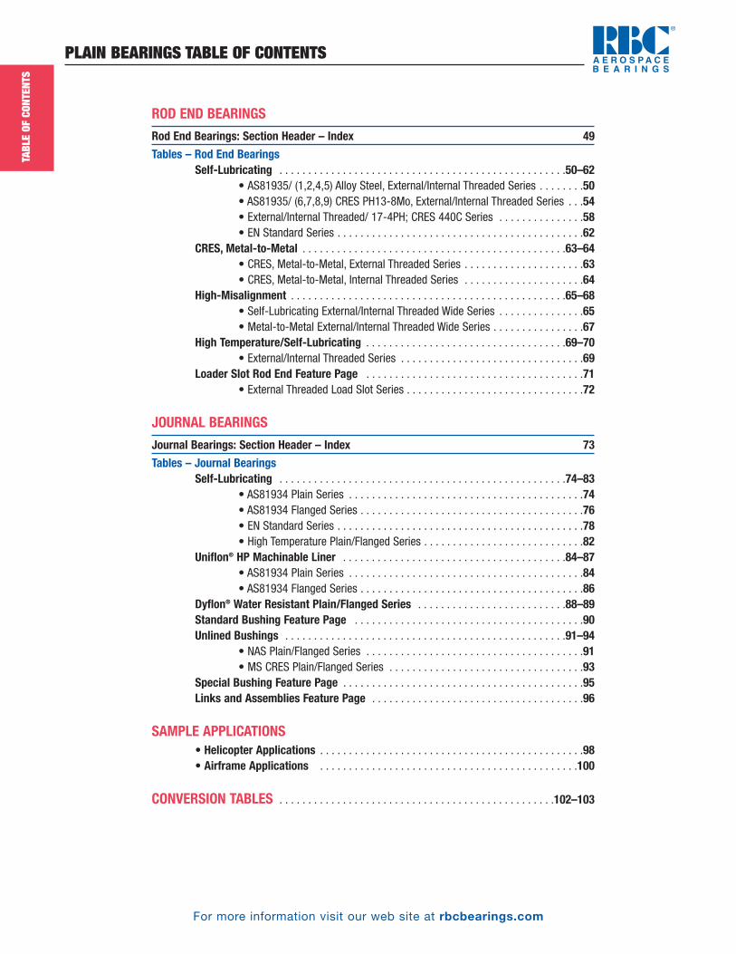
ROD END BEARINGS
Rod End Bearings: Section Header – Index 49
Tables – Rod End BearingsSelf-Lubricating . . . . . . . . . . . . . . . . . . . . . . . . . . . . . . . . . . . . . . . . . . . . . . . . . .50–62
• AS81935/ (1,2,4,5) Alloy Steel, External/Internal Threaded Series . . . . . . . .50• AS81935/ (6,7,8,9) CRES PH13-8Mo, External/Internal Threaded Series . . .54• External/Internal Threaded/ 17-4PH; CRES 440C Series . . . . . . . . . . . . . . .58• EN Standard Series . . . . . . . . . . . . . . . . . . . . . . . . . . . . . . . . . . . . . . . . . . .62
CRES, Metal-to-Metal . . . . . . . . . . . . . . . . . . . . . . . . . . . . . . . . . . . . . . . . . . . . . .63–64• CRES, Metal-to-Metal, External Threaded Series . . . . . . . . . . . . . . . . . . . . .63• CRES, Metal-to-Metal, Internal Threaded Series . . . . . . . . . . . . . . . . . . . . .64
High-Misalignment . . . . . . . . . . . . . . . . . . . . . . . . . . . . . . . . . . . . . . . . . . . . . . . .65–68• Self-Lubricating External/Internal Threaded Wide Series . . . . . . . . . . . . . . .65• Metal-to-Metal External/Internal Threaded Wide Series . . . . . . . . . . . . . . . .67
High Temperature/Self-Lubricating . . . . . . . . . . . . . . . . . . . . . . . . . . . . . . . . . . .69–70• External/Internal Threaded Series . . . . . . . . . . . . . . . . . . . . . . . . . . . . . . . .69
Loader Slot Rod End Feature Page . . . . . . . . . . . . . . . . . . . . . . . . . . . . . . . . . . . . . .71• External Threaded Load Slot Series . . . . . . . . . . . . . . . . . . . . . . . . . . . . . . .72
JOURNAL BEARINGS
Journal Bearings: Section Header – Index 73
Tables – Journal BearingsSelf-Lubricating . . . . . . . . . . . . . . . . . . . . . . . . . . . . . . . . . . . . . . . . . . . . . . . . . .74–83
• AS81934 Plain Series . . . . . . . . . . . . . . . . . . . . . . . . . . . . . . . . . . . . . . . . .74• AS81934 Flanged Series . . . . . . . . . . . . . . . . . . . . . . . . . . . . . . . . . . . . . . .76• EN Standard Series . . . . . . . . . . . . . . . . . . . . . . . . . . . . . . . . . . . . . . . . . . .78• High Temperature Plain/Flanged Series . . . . . . . . . . . . . . . . . . . . . . . . . . . .82
Uniflon® HP Machinable Liner . . . . . . . . . . . . . . . . . . . . . . . . . . . . . . . . . . . . . . .84–87• AS81934 Plain Series . . . . . . . . . . . . . . . . . . . . . . . . . . . . . . . . . . . . . . . . .84• AS81934 Flanged Series . . . . . . . . . . . . . . . . . . . . . . . . . . . . . . . . . . . . . . .86
Dyflon® Water Resistant Plain/Flanged Series . . . . . . . . . . . . . . . . . . . . . . . . . .88–89Standard Bushing Feature Page . . . . . . . . . . . . . . . . . . . . . . . . . . . . . . . . . . . . . . . .90Unlined Bushings . . . . . . . . . . . . . . . . . . . . . . . . . . . . . . . . . . . . . . . . . . . . . . . . .91–94
• NAS Plain/Flanged Series . . . . . . . . . . . . . . . . . . . . . . . . . . . . . . . . . . . . . .91• MS CRES Plain/Flanged Series . . . . . . . . . . . . . . . . . . . . . . . . . . . . . . . . . .93
Special Bushing Feature Page . . . . . . . . . . . . . . . . . . . . . . . . . . . . . . . . . . . . . . . . . .95Links and Assemblies Feature Page . . . . . . . . . . . . . . . . . . . . . . . . . . . . . . . . . . . . .96
SAMPLE APPLICATIONS• Helicopter Applications . . . . . . . . . . . . . . . . . . . . . . . . . . . . . . . . . . . . . . . . . . . . . .98• Airframe Applications . . . . . . . . . . . . . . . . . . . . . . . . . . . . . . . . . . . . . . . . . . . . .100
CONVERSION TABLES . . . . . . . . . . . . . . . . . . . . . . . . . . . . . . . . . . . . . . . . . . . . . . . .102–103
PB_Index_8-29-16_Pln_Index.qxd 8/29/16 8:36 PM Page 2
5.*15&�%&3*(.�3/,54
*/.3
4/�$/-0,&8�02/#,&-
3
�)&��,/#",��&"%&2�*
.��&2/30"$&��&"2*.
(3
Aircraft Control Bearings
Ball Bearing Rod Ends
Needle Track Roller Bearings
Thin Section Ball Bearings
Custom Bearing Applications
www.rbcbearings.com
Rolling Element Bearings
Rolling Element Bearings
� �� � �
��
� � � ��
� ��
� � � � ��
� �� � �
� �� �
� �� � �
�� � � �
�
��
�
� � � � ��
� �� � �
� �� �
� �� � �
�� � � �
�
� � � � � � � �
� � � � � � �
� � �
��
�
� ��
� � � �
�� �
� � � � � �
� �� �
�� � �
�
� � ��
� �� �
��
�
� �
� � �
��
��
�� �
� �� � � � �
� �� � �
�� � � �
�
� � � � ��
� �� � � �
� � � � � �
� �� � � �
� � � � � �
� � � � � �
� � � � � �
�� � �
�� � � �
� ��
� ��
� � � � �
� �
� �� � � � � �
� �� � � �
��
� � � �
� � � �
� �� � �
�
�� �
��
� � � � �
�
� �� � �
�� � � �
�
� � � � �
� �� � � �
� � � � � �
� � � � > �� � �
�� � �
� � � � � � �� � � �
� ��
� � �� �
� �
�� � � � � � �
� � � � � � � �� � � � � � � �
� � � �
� � � � � � � � � � � � �� � � � � �
� � � � � � � � � � � � � � � � � � � � � > � � � �
> �
©2008, 2011, 2016 RBC Bearings Incorporated. All rights reserved.
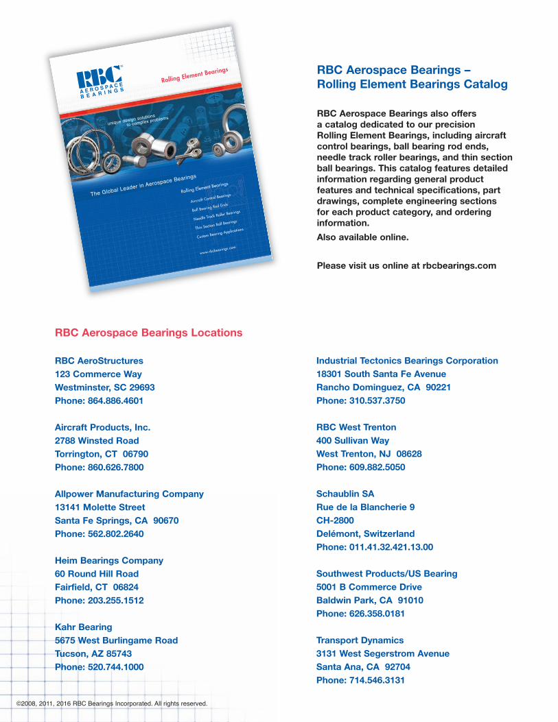
RBC Aerospace Bearings – Rolling Element Bearings Catalog
RBC Aerospace Bearings also offersa catalog dedicated to our precisionRolling Element Bearings, including aircraftcontrol bearings, ball bearing rod ends,needle track roller bearings, and thin sectionball bearings. This catalog features detailedinformation regarding general productfeatures and technical specifications, partdrawings, complete engineering sectionsfor each product category, and orderinginformation.
Also available online.
Please visit us online at rbcbearings.com
Industrial Tectonics Bearings Corporation18301 South Santa Fe AvenueRancho Dominguez, CA 90221Phone: 310.537.3750
RBC West Trenton400 Sullivan WayWest Trenton, NJ 08628Phone: 609.882.5050
Schaublin SARue de la Blancherie 9CH-2800Delémont, SwitzerlandPhone: 011.41.32.421.13.00
Southwest Products/US Bearing5001 B Commerce DriveBaldwin Park, CA 91010Phone: 626.358.0181
Transport Dynamics 3131 West Segerstrom AvenueSanta Ana, CA 92704Phone: 714.546.3131
RBC Aerospace Bearings Locations
RBC AeroStructures123 Commerce WayWestminster, SC 29693Phone: 864.886.4601
Aircraft Products, Inc.2788 Winsted RoadTorrington, CT 06790Phone: 860.626.7800
Allpower Manufacturing Company13141 Molette StreetSanta Fe Springs, CA 90670Phone: 562.802.2640
Heim Bearings Company60 Round Hill RoadFairfield, CT 06824Phone: 203.255.1512
Kahr Bearing5675 West Burlingame RoadTucson, AZ 85743Phone: 520.744.1000
PB_002_8-29-16_Pln_CvrPgs.qxd 8/29/16 8:19 PM Page 2
INTR
ODUC
TION
For more information visit our web site at rbcbearings.com
RBC BEARINGS
3
©2008, 2011, 2016 RBC Bearings Incorporated. All rights reserved.
INDUSTRIAL HERITAGE AND KNOW-HOW
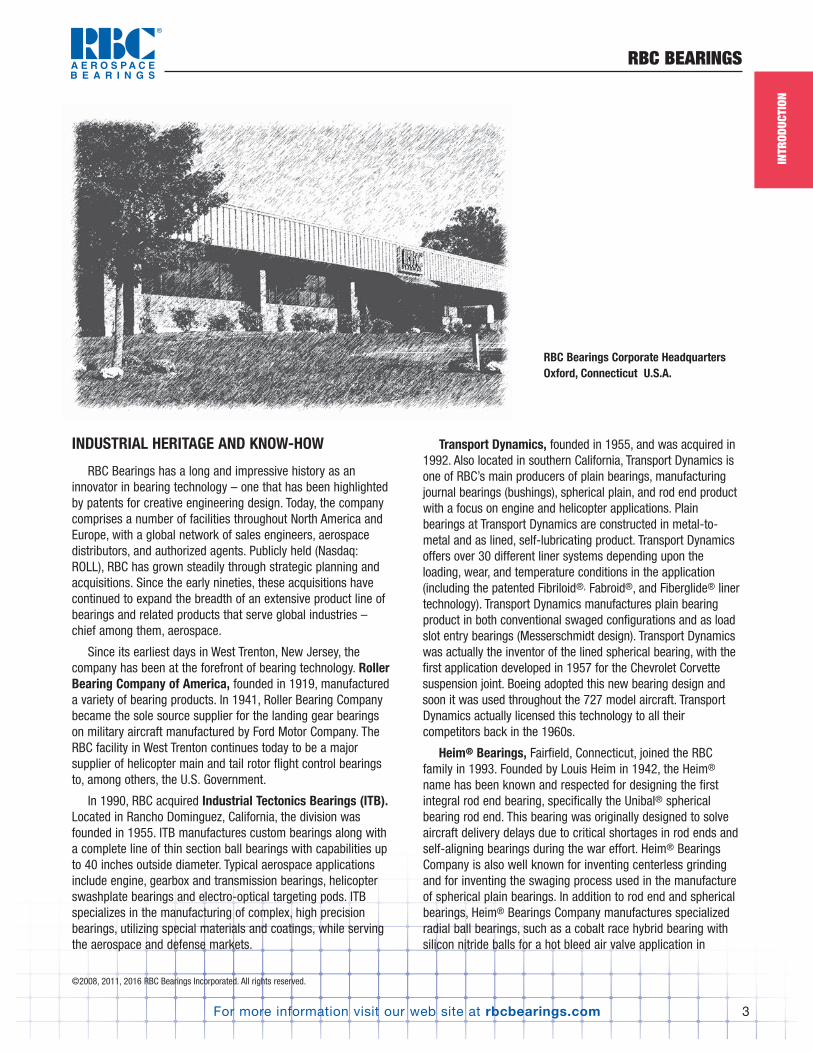
RBC Bearings has a long and impressive history as aninnovator in bearing technology – one that has been highlightedby patents for creative engineering design. Today, the companycomprises a number of facilities throughout North America andEurope, with a global network of sales engineers, aerospacedistributors, and authorized agents. Publicly held (Nasdaq:ROLL), RBC has grown steadily through strategic planning andacquisitions. Since the early nineties, these acquisitions havecontinued to expand the breadth of an extensive product line ofbearings and related products that serve global industries –chief among them, aerospace.
Since its earliest days in West Trenton, New Jersey, thecompany has been at the forefront of bearing technology. RollerBearing Company of America, founded in 1919, manufactureda variety of bearing products. In 1941, Roller Bearing Companybecame the sole source supplier for the landing gear bearingson military aircraft manufactured by Ford Motor Company. TheRBC facility in West Trenton continues today to be a majorsupplier of helicopter main and tail rotor flight control bearingsto, among others, the U.S. Government.
In 1990, RBC acquired Industrial Tectonics Bearings (ITB).Located in Rancho Dominguez, California, the division wasfounded in 1955. ITB manufactures custom bearings along witha complete line of thin section ball bearings with capabilities upto 40 inches outside diameter. Typical aerospace applicationsinclude engine, gearbox and transmission bearings, helicopterswashplate bearings and electro-optical targeting pods. ITBspecializes in the manufacturing of complex, high precisionbearings, utilizing special materials and coatings, while servingthe aerospace and defense markets.
Transport Dynamics, founded in 1955, and was acquired in1992. Also located in southern California, Transport Dynamics isone of RBC’s main producers of plain bearings, manufacturingjournal bearings (bushings), spherical plain, and rod end productwith a focus on engine and helicopter applications. Plainbearings at Transport Dynamics are constructed in metal-to-metal and as lined, self-lubricating product. Transport Dynamicsoffers over 30 different liner systems depending upon theloading, wear, and temperature conditions in the application(including the patented Fibriloid®, Fabroid®, and Fiberglide® linertechnology). Transport Dynamics manufactures plain bearingproduct in both conventional swaged configurations and as loadslot entry bearings (Messerschmidt design). Transport Dynamicswas actually the inventor of the lined spherical bearing, with thefirst application developed in 1957 for the Chevrolet Corvettesuspension joint. Boeing adopted this new bearing design andsoon it was used throughout the 727 model aircraft. TransportDynamics actually licensed this technology to all theircompetitors back in the 1960s.
Heim® Bearings, Fairfield, Connecticut, joined the RBCfamily in 1993. Founded by Louis Heim in 1942, the Heim®
name has been known and respected for designing the firstintegral rod end bearing, specifically the Unibal® sphericalbearing rod end. This bearing was originally designed to solveaircraft delivery delays due to critical shortages in rod ends andself-aligning bearings during the war effort. Heim® BearingsCompany is also well known for inventing centerless grindingand for inventing the swaging process used in the manufactureof spherical plain bearings. In addition to rod end and sphericalbearings, Heim® Bearings Company manufactures specializedradial ball bearings, such as a cobalt race hybrid bearing withsilicon nitride balls for a hot bleed air valve application in
RBC Bearings Corporate HeadquartersOxford, Connecticut U.S.A.
PB_003_006_8-29-16_Pln_003_006.qxd 8/29/16 8:21 PM Page 3

INTR
ODUC
TION
For more information visit our web site at rbcbearings.com
RBC BEARINGS
4
©2008, 2011, 2016 RBC Bearings Incorporated. All rights reserved.
aircraft auxiliary power units, suspension applications onMilitary land vehicles, elastomeric bearings and machinableliner systems. Heim® Bearings Company is also the world’slargest provider of aerospace ball bearing rod ends, includingmanufacture with the corrosion-resistant AeroCres® material.Ball bearing rod ends can be found throughout aircraft inpositioning and linkage assemblies, as well as on swaged tubesthroughout the airframe.
In 2000, RBC acquired Schaublin SA based in Delémont,Switzerland. As a result, RBC added Schaublin’s metric rod endsand metric spherical bearings to the family of global RBCproducts, and a base with which to service the Europeanmarket. Within this 140,000 sq. ft. facility, RBC has establishedthe company’s European Distribution Center. In addition,Schaublin was licensed by Heim® Bearings to market Unibal®rod ends back in the 1950s. Schaublin specializes in lightweight titanium bearing solutions, including next levelassemblies utilizing integral split ball designs for the aerospaceindustry. RBC also acquired what is now called RBC France —a sales, engineering, marketing, and distribution arm forSchaublin product, located in Les Ulis, France.
In December, 2003, RBC acquired the business of the formerTorrington “Standard” Plant — a long-established leader inairframe products. This facility, referred to as RBC Aircraft Products, Inc. (API) was founded in 1866. The Torrington name is synonymous with quality engineering and precision –and complements the RBC portfolio of aerospace productofferings. At the API plant, RBC produces aircraft needle track roller bearings, lined track rollers, cam followers, radialball bearings, and is RBC’s main facility for the production of52100 cad plated, 440C stainless, and zinc nickel plate airframecontrol ball bearings. RBC has become the number oneproducer worldwide of airframe control product and has virtuallyevery series and size Mil Spec approval along with an extensivelist of European approvals.
RBC has made an additional aerospace business acquisitionin each of the years 2004, 2005, and 2006; acquiring U.S.Bearing, Chatsworth, California; Southwest Products Inc.,Baldwin Park, California; and Allpower Manufacturing, SantaFe Springs, California, respectively. Southwest Products/USBearings has the capability to offer unique swaged bearingsolutions (up to 11" OD), in addition to low friction liners andhard coat machining. The product offering has evolved toinclude split ball spherical and rod ends, large trunnionbearings, specialty rod ends and solid and welded links.SWP/USB has played a major role in the design and support ofplain bearings for commercial and military aircraft, helicopter,power plant, satellite, military land vehicle and submarine
applications. Allpower Manufacturing, a Boeing and Airbusapproved supplier, produces a full line of precision bushings,spacers, sleeves, and specialty machined parts servicing theaerospace industry. Capable of offering specialized materials, All Power is proficient with stainless steel, carbon steel,beryllium copper, Inconel®, titanium, aluminum, aluminumbronze and colbalt raw materials, to name a few.
In December, 2008, RBC acquired A.I.D. Corporation, nowrecognized as RBC AeroStructures, located in Westminster, SC.RBC AeroStructures compliments the RBC product offering byproducing tight tolerance, precision fabricated tubular andmachined parts. With a primary focus on fixed-wing and rotary-wing aircraft, some typical applications include: control rods,push-pull rods, connecting links, torque tubes, rod assemblies,struts and cargo tie-downs. This is a vertically intergratedproduct line to the already broadest line of aerospace bearingsoffered by RBC in the industry.
In April, 2015, RBC aquired Kahr Bearings, as part of theSargent Aerospace and Defense acquisition. Located inTucson, AZ, Kahr specializes in the design and manufacture ofPTFE lined and metal-to-metal monoball and sliding elementbearings for military and commercial aircraft and rotorcraft,industrial and passenger railcars, and military marineapplications. Kahr’s line of Kahr-Lon® liner systems consists of10 different liner systems which excel in high vibration and highload environments and are common in many aerospace andindustrial applications.
Aerospace Segments Served
Aerospace segments served by RBC include commercial andmilitary alike, fixed and rotary wing. RBC serves the world’smajor airframers (large transport, regional, and generalaviation), engines and accessories, defense (land and marinevehicles, missile and bomb, optical targeting), space (vehiclesand engine), major subsystem providers (landing gear, electricalgeneration, etc.), and smaller subsystem and componentapplications (primary and secondary flight control actuation,swaged tube bearing, and structural applications, etc.)
RBC’s aerospace operations count among their customers a long list of prestigious names, including Airbus, Boeing,Lockheed Martin, SAAB, Northrop Grumman, BAE Systems,Bombardier, Embraer Aircraft, Spirit Aerosystems, NASA, BellHelicopter, Sikorsky, Boeing Mesa and Rotocrafts, Rolls-Royce,GE Aircraft Engines, Snecma, Pratt & Whitney, Honeywell, ASCO,Goodrich Aerospace, Moog, Smiths Aerospace, ParkerAerospace, Messier-Dowty, Raytheon, Primus University Swage,LeFiell, and Tyee.
PB_003_006_8-29-16_Pln_003_006.qxd 8/29/16 8:21 PM Page 4
INTR
ODUC
TION
For more information visit our web site at rbcbearings.com
RBC BEARINGS
5
©2008, 2011, 2016 RBC Bearings Incorporated. All rights reserved.
The RBC aerospace divisions are well versed in the manybearing materials, from the standard chrome 52100, to theCRES 440C and 15-5/17-4 stainless product, to the processingof exotic materials like ALTEMP® A286*, Stellite®**, titanium,Inconel®***, beryllium copper, Pyrowear®, and AeroCres®.
Combined revenue of the RBC aircraft divisions, isapproximately 75% aerospace. The predominant non-aerospacemarkets include high-end industrial applications requiring thesame stringent tolerances and high-quality precision product.
Quality Statement
All of RBC’s aerospace bearings divisions have a formal,documented, and aerospace-approved quality program/system inplace. The company is approved to many OEM quality systems,including Airbus, Rolls-Royce, Pratt & Whitney, GE AircraftEngines, Boeing Commercial Aircraft, Boeing Helicopter, Sikorsky,Lockheed Martin, Northrop Grumman, Snecma, Goodrich, BAESystems, and the U.S. Government, among others. RBC is on aself-release program with many of these companies.
For example, Industrial Tectonic Bearings (ITB), RanchoDominguez, California, was promoted to Gold Level PreferredSupplier status at Lockheed Martin Missiles and Fire Control,Orlando, Florida. At this point, RBC is the only Gold bearingsupplier to the Lockheed organization. In a statement given by asenior manager for Lockheed Martin Missiles and Fire Control,“…the ITB facility is key in helping us create a world-classsupply base.” To assess ITB’s supplier status, Lockheed Martinperformed an on-site business system review, the teamconcluding that RBC demonstrated a dedication to continuousimprovement and process improvement. The Gold status allowsITB to perform its own final inspection of hardware, facilitating a“dock-to-stock” receipt at Lockheed Martin’s Orlando factory.
All aerospace divisions of RBC are ISO 9001:2000 andAS9100 certified. Additionally, they are NADCAP accredited in-house for non-destructive testing, heat treat, and weld, or areusing NADCAP accredited sourcing. The company is constantlyaudited by the many major aerospace customers in the world,as well as by the FAA. RBC is aware that material, specification,and/or processing changes are all critical. As such, the companyhas a traceability process for its manufacturing locationsincluding a procedure for preserving the identity and origin ofthe bearing and all its components. RBC has the capability toisolate and recall suspect bearings from use and trace thecause of failure to a specific manufacturing lot, materialprocess, or component.
Strategic Plan and Vision
RBC Bearings’ strategic plan and vision is to continue downthe path of profitability and growth — organic growth includingmarket penetration and the addition of new products andgrowth via acquisition to which RBC’s uncompromising trackrecord of aerospace acquisition attests. RBC has become theworld’s broadest supplier of aerospace bearing product, servingthe industry with spherical, rod end, and journal plain bearings,ball bearings, cylindrical roller bearings, needle track rollerbearings, cam follower bearings, tapered roller bearings,airframe control, thin section ball bearings, and ball bearing rodends. RBC is focused on the aerospace industry and intends tocontinually complement its broad offering with new products,new technologies, and acquisitions.
RBC has a long tradition of engineering design excellenceand innovation in creating solutions to problems, as our patentsreflect. The company also strives to stay on the forefront ofbearing material, plating, and design technology. Investing inqualified personnel, capital equipment, material and bearingtesting is paramount. RBC also strives to continually refine itsmanufacturing processes, both to maintain the reputation forquality product and long life, and to remain the industry’s costleader.
A very important part of our strategic vision is todevelop/expand on a current business partnership with targetedcustomers. RBC’s goals, objectives, and investments support theaerospace market, while many companies are choosing to exitthe industry. RBC believes that its objectives are soundly alignedwith the needs of the aerospace industry, both short and longterm. All of us at RBC look forward to supplying more of ouraircraft offerings through all the RBC aerospace divisionsparticipating in your business.
Warranty
RBC’s sole warranty is against defects in materials orworkmanship. The foregoing warranty is exclusive, and in lieu of all other warranties (whether written, oral or implied)including, but not limited to, the warranty of merchantability,and the warranty of fitness for a particular purpose. A no chargereplacement will be made on any product manufactured byRBC, which upon examination by RBC, appears to be defective,provided it is returned to RBC, transportation prepaid, withinninety (90) days of date of sale, and further provided it has been properly selected, installed or mounted and lubricated and not subject to abuse.
Pyrowear® is a registered trademark of Carpenter Technology Corporation.*ALTEMP® A286 is a registered trademark of ATI Allegheny Ludlum.**Stellite® is a registered trademark of the Deloro Stellite Company, Inc.***Inconel® is a registered trademark of Alloys International, Inc. and
The international Nickel Company, Inc.
PB_003_006_8-29-16_Pln_003_006.qxd 8/29/16 8:21 PM Page 5

INTR
ODUC
TION
For more information visit our web site at rbcbearings.com
RBC BEARINGS
6
©2008, 2011, 2016 RBC Bearings Incorporated. All rights reserved.
CONTACT US
Domestic
Corporate HeadquartersOne Tribology Center102 Willenbrock RoadOxford, CT 06478Phone: 203.267.7001Fax: 203.267.5012
RBC AeroStructures123 Commerce WayWestminster, SC 29693Phone: 864.886.4601Fax: 864.886.4615
Aircraft Products, Inc2788 Winsted RoadTorrington, CT 06790Phone: 860.626.7800Fax: 860.626.7886
Allpower Manufacturing Company13141 Molette StreetSanta Fe Springs, CA 90670Phone: 562.802.2640Fax: 562.921.9933
Heim Bearings Company60 Round Hill RoadFairfield, CT 06824Phone: 203.255.1512Fax: 203.319.7709
Kahr Bearing5675 West Burlingame RoadTucson, AZ 85743Phone: 520.744.1000Fax: 520.744.9494
Industrial Tectonics BearingsCorporation18301 South Santa Fe AvenueRancho Dominguez, CA 90221Phone: 310.537.3750Fax: 310.537.2909
RBC West Trenton400 Sullivan WayWest Trenton, NJ 08628Phone: 609.882.5050Fax: 609.882.5533
Southwest Products Inc./US Bearing5001 B Commerce DriveBaldwin Park, CA 91010Phone: 626.358.0181Fax: 626.303.6141
Transport Dynamics3131 W. Segerstrom AvenueSanta Ana, CA 92704.9998Phone: 714.546.3131Fax: 714.545.9885
International
RBC France SAS19, Avenue de NorvegeZA de Courtaboeuf 191953 Les Ulis CedexFrancePhone: 011.33.1.60.92.17.35Fax: 011.33.1.69.86.12.84
Schaublin SARue de la Blancherie 9CH-2800 DelémontSwitzerlandPhone: 011.41.32.421.13.00Fax: 011.41.32.421.1301
PB_003_006_8-29-16_Pln_003_006.qxd 8/29/16 8:21 PM Page 6
For more information visit our web site at rbcbearings.com
ENGINEERING FOR SPHERICALS, ROD ENDS, AND JOURNALS
7
PLAI
N BE
ARIN
GS
©2008, 2011, 2016 RBC Bearings Incorporated. All rights reserved.
SAE/MS/ENSpecification DescriptionM81934/1. . . . . . . . . . . . . . . . . Journals, Plain, Self-lubricatingM81934/2. . . . . . . . . . . . . . . . . Journals, Flanged,
Self-lubricatingM81935/1. . . . . . . . . . . . . . . . . Rod End, Male threads,
Wide, Self-lubricatingM81935/2. . . . . . . . . . . . . . . . . Rod End, Female threads,
Wide, Self-lubricatingM81935/4. . . . . . . . . . . . . . . . . Rod End, Male threads,
Narrow, Self-lubricatingM81935/5. . . . . . . . . . . . . . . . . Rod End, Female threads,
Narrow, Self-lubricatingMS14101 . . . . . . . . . . . . . . . . . Spherical bearings,
Self-lubricating, Narrow, Grooved
MS14102 . . . . . . . . . . . . . . . . . Spherical bearings, Self-lubricating, Wide, Chamfered
MS14103 . . . . . . . . . . . . . . . . . Spherical bearings, Self-lubricating, Wide, Grooved
MS14104 . . . . . . . . . . . . . . . . . Spherical bearings, Self-lubricating, Narrow, Chamfered
MS14101A . . . . . . . . . . . . . . . . Extended Life, Sphericalbearings, Self-lubricating,Narrow, Grooved
MS14102A . . . . . . . . . . . . . . . . Extended Life, Sphericalbearings, Self-lubricating, Wide, Chamfered
MS14103A . . . . . . . . . . . . . . . . Extended Life, Sphericalbearings, Self-lubricating, Wide, Grooved
MS14104A . . . . . . . . . . . . . . . . Extended Life, Sphericalbearings, Self-lubricating, Narrow, Chamfered
M81820/1. . . . . . . . . . . . . . . . . Spherical bearing, Self-lubricating, Narrow,Grooved, Lined bore
M81820/2. . . . . . . . . . . . . . . . . Spherical bearing, Self-lubricating, Wide,Chamfered, Lined bore
M81820/3. . . . . . . . . . . . . . . . . Spherical bearing, Self-lubricating, Wide, Grooved, Lined bore
SAE/MS/ENSpecification DescriptionM81820/4. . . . . . . . . . . . . . . . . Spherical bearing,
Self-lubricating, Narrow,Chamfered, Lined bore
M81936/1. . . . . . . . . . . . . . . . . Spherical bearing, BeCu ball grooved outer ring
M81936/2. . . . . . . . . . . . . . . . . Spherical bearing, BeCu ball chamfered outer ring
EN2285. . . . . . . . . . . . . . . . . . . Journals, Plains, Self-lubricating aluminum alloy
EN2286. . . . . . . . . . . . . . . . . . . Journals, Flanged,Self-lubricating aluminum alloy
EN2287. . . . . . . . . . . . . . . . . . . Journals, Plain, Self-lubricating corrosion resistant steel
EN2288. . . . . . . . . . . . . . . . . . . Journals, Flanged, Self-lubricating corrosion resistant steel
EN6056. . . . . . . . . . . . . . . . . . . Rod End, Self-lubricating,Threaded shank
EN2022. . . . . . . . . . . . . . . . . . . Spherical bearing, Self-lubricated, Light series, Chamfered and grooved
EN2023. . . . . . . . . . . . . . . . . . . Spherical bearing,Self-lubricated, Standard series, Chamferedand grooved outer ring
EN2335. . . . . . . . . . . . . . . . . . . Spherical bearing, Metal-to-metal, Chamfered and grooved outer ring
EN2501. . . . . . . . . . . . . . . . . . . Spherical bearing, Self-Lubricated, High Misalignment
EN4613. . . . . . . . . . . . . . . . . . . Spherical bearing, Self-lubricating, Narrow inch sizes
EN4614. . . . . . . . . . . . . . . . . . . Spherical bearing Self-lubricated, Wide inch sizes
PLAIN BEARINGS ENGINEERINGRBC offers many types and sizes of plain bearings to the
aerospace industry. Both metal-to-metal and self-lubricatingbearings are featured in this catalog. These bearings have beenqualified to stringent SAE, Military, NAS, AECMA, and customerdesign and performance standards in RBC test laboratories.
For information on special plain bearings or the many standardseries of commercial plain bearings, that are available from RBC,consult the appropriate RBC Aerospace Bearings sales engineer.
The RBC bearing series, which apply to various standardsare shown below:
PB_007_017_8-29-16_Pln_007_017.qxd 8/30/16 10:47 AM Page 7
For more information visit our web site at rbcbearings.com
ENGINEERING FOR SPHERICALS, ROD ENDS, AND JOURNALS
8
PLAI
N BE
ARIN
GS
©2008, 2011, 2016 RBC Bearings Incorporated. All rights reserved.
CONFIGURATIONSSpherical bearings, shown in this catalog, are assembled
by forming the outer ring (race) over the inner ring (ball). Theprocesses used by RBC assure excellent conformity of thespherical surfaces of the outer ring bore to the spherical innerring O.D.
Rod Ends in this catalog have several different designs andoptions. Rod ends are manufactured by inserting an MS or ENself-lubricating bearing into the rod end body. Rod ends areavailable with right or left-handed, male-threaded or female-threaded shanks. Male-threaded shanks are also available withkeyway slots and female threads are available with end slots forlocking devices.
Journal Bearings are offered in both flanged and non-flanged versions. In this catalog the journal bearings are all self-lubricating.
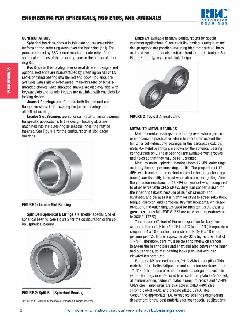
Loader Slot Bearings are spherical metal-to-metal bearingsfor specific applications. In this design, loading slots aremachined into the outer ring so that the inner ring may beinserted. See Figure 1 for the configuration of slot loaderbearings.
FIGURE 1: Loader Slot Bearing
Split Ball Spherical Bearings are another special type ofspherical bearing. See Figure 2 for the configuration of the spitball spherical bearing.
FIGURE 2: Split Ball Spherical Bearing
Links are available in many configurations for specialcustomer applications. Since each link design is unique, manydesign options are possible, including high temperature linersand light weight materials such as aluminum and titanium. SeeFigure 3 for a typical aircraft link design.
FIGURE 3: Typical Aircraft Link
METAL-TO-METAL BEARINGSMetal-to-metal bearings are primarily used where grease
maintenance is practical or where temperatures exceed thelimits for self-lubricating bearings. In this aerospace catalog,metal-to-metal bearings are shown for the spherical bearingconfiguration only. These bearings are available with groovesand holes so that they may be re-lubricated.
Metal-to-metal, spherical bearings have 17-4PH outer ringsand beryllium copper inner rings (balls). The properties of 17-4PH, which make it an excellent choice for bearing outer rings(races), are its ability to resist wear, abrasion, and galling. Also,the corrosion resistance of 17-4PH is excellent when comparedto other hardenable CRES steels. Beryllium copper is used forthe inner rings (balls) because of its high strength andhardness, and because it is highly resistant to stress relaxation,fatigue, abrasion, and corrosion. Dry-film lubricants, which arebonded to the outer ring, are used for high temperatures, andgreases such as MIL-PRF-81322 are used for temperatures upto 350°F (177°C).
The mean coefficient of thermal expansion for berylliumcopper in the +70°F to +400°F (+21°C to +204°C) temperaturerange is 9.4 x 10⁻⁶ inches per inch per °F (16.9 x 10⁻⁶ mm per mm per °C). This is approximately 33% higher than that of17-4PH. Therefore, care must be taken to review clearancesbetween the bearing bore and shaft and also between the innerand outer rings, so that bearing lock up will not occur atelevated temperatures.
For some MS rod end bodies, PH13-8Mo is an option. Thismaterial offers better fatigue life and corrosion resistance than17-4PH. Other series of metal-to-metal bearings are availablewith outer rings manufactured from cadmium plated 4340 steel,aluminum bronze, cadmium plated aluminum bronze and 17-4PHCRES steel. Inner rings are available in CRES 440C steel,chrome plated 440C, and chrome plated 52100 steel. Consult the appropriate RBC Aerospace Bearings engineeringdepartment for the best materials for your special applications.
PB_007_017_8-29-16_Pln_007_017.qxd 8/30/16 10:47 AM Page 8
For more information visit our web site at rbcbearings.com
ENGINEERING FOR SPHERICALS, ROD ENDS, AND JOURNALS
9
PLAI
N BE
ARIN
GS
©2008, 2011, 2016 RBC Bearings Incorporated. All rights reserved.
SELF-LUBRICATING BEARINGSSelf-lubricating bearings are available in spherical, journal,
flanged journal, and rod end bearing configurations. They wereoriginally developed to eliminate the need for relubrication, toprovide lower torque, and to solve application problems whereconventional metal-to-metal bearings would not performsatisfactorily; such as with high frequency vibration.
The liner systems for self-lubricating bearings do not requiresupplemental lubrication. The polytetrafluoroethylene (PTFE) fibersin the liner act as the lubricant. When a bearing is operated, thepressure and movement of the inner ring shears PTFE from theliner system. As the bearing operates, the PTFE is burnished intothe metal and also into the liner surfaces, thereby reducing thecoefficient of friction. After the coefficient of friction becomessufficiently low, no further PTFE is sheared from the liner. Throughcontinued use, some PTFE on the surfaces may exit the bearing.When this occurs, friction increases and more PTFE is shearedfrom the liner and deposited on the ring and liner surfaces.
Self-lubricating spherical bearings are available in manycombinations of ring and liner materials. Typically, inner rings (balls)used in SAE/Military Standards are 440C or PH13-8Mo, and outerrings (races) are 17-4PH. High temperature materials are alsoavailable.
Self-lubricating journal bearings are available with avariety of backing materials. Standard materials for SAE/Militarystandards include 17-4PH CRES steel and 7075-T6 and 2024-T851 aluminum alloys.
Rod ends have the bodies manufactured from 17-4PH or PH13-8Mo CRES steel or cadmium plated 4340 steel.
Light weight rod ends and spherical bearings are nowbeing offered by RBC with titanium components to meetdemanding aerospace application requirements.
LINER SYSTEMSRBC provides six standard liner systems, that are qualified to
SAE and AECMA performance standards. These are shown inTable 1 below:
Bearing Configuration Standard Liner SystemsUniflon® E
SphericalFabroid® IIG2Fibriloid®
Kahr-Lon® X1200SUniflon® EFiberglide® V
JournalFabroid® IIG2Fibriloid®
Uniflon® HPKahr-Lon® X1200SUniflon® E
Rod endFabroid® IIG2Fibriloid®
Kahr-Lon® X1200S
TABLE 1: Standard RBC liner systems
RBC Bearings manufactures five different self-lubricating linermaterials that are qualified to AS81820. In addition, over 60 otherself-lubricating materials are available for specific characteristics;such as high temperature for turbine engine applications ormachinability for airframe, helicopter, and landing gear applications.
The construction of most RBC liner systems revolves arounda woven fabric where PTFE fibers are woven with othersupporting and bondable fibers. The process used to producethe PTFE fibers results in a fiber, which has 25 times the tensilestrength of that of the base resin. The weave of the fabricexposes the PTFE fibers on the working surface. The supportingfibers are interwoven with the PTFE fibers and arepredominantly exposed on the surface that is bonded. Thisconstruction provides a positive locking of the PTFE fibers forstrength and resistance to cold flow. It also provides a highstrength bond to the backing material of the bearing.
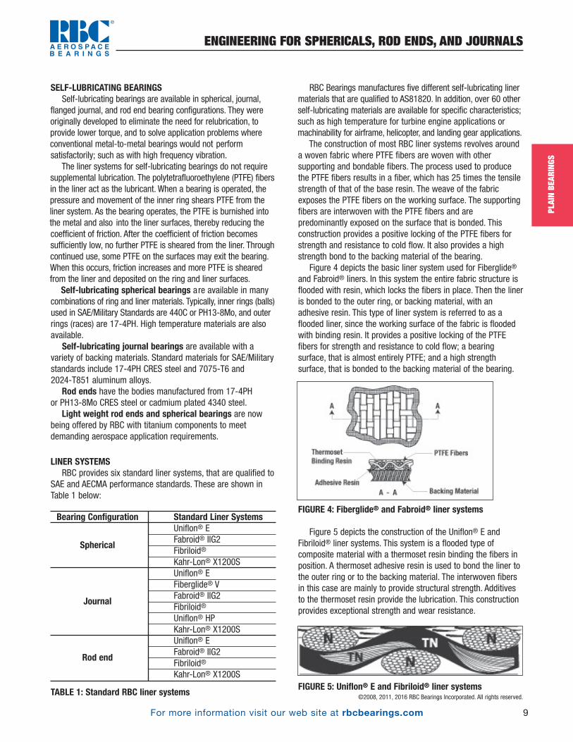
Figure 4 depicts the basic liner system used for Fiberglide®
and Fabroid® liners. In this system the entire fabric structure isflooded with resin, which locks the fibers in place. Then the lineris bonded to the outer ring, or backing material, with anadhesive resin. This type of liner system is referred to as aflooded liner, since the working surface of the fabric is floodedwith binding resin. It provides a positive locking of the PTFEfibers for strength and resistance to cold flow; a bearingsurface, that is almost entirely PTFE; and a high strengthsurface, that is bonded to the backing material of the bearing.
FIGURE 4: Fiberglide® and Fabroid® liner systems
Figure 5 depicts the construction of the Uniflon® E andFibriloid® liner systems. This system is a flooded type ofcomposite material with a thermoset resin binding the fibers inposition. A thermoset adhesive resin is used to bond the liner tothe outer ring or to the backing material. The interwoven fibersin this case are mainly to provide structural strength. Additivesto the thermoset resin provide the lubrication. This constructionprovides exceptional strength and wear resistance.
FIGURE 5: Uniflon® E and Fibriloid® liner systems
PB_007_017_8-29-16_Pln_007_017.qxd 8/30/16 10:47 AM Page 9

For more information visit our web site at rbcbearings.com
ENGINEERING FOR SPHERICALS, ROD ENDS, AND JOURNALS
10
PLAI
N BE
ARIN
GS
©20
08, 2
011,
201
6 RB
C Be
arin
gs In
corp
orat
ed. A
ll rig
hts
rese
rved
.
There are nine liner systems presented in this catalog (andmany others for special application).
Uniflon® E liner system. The Uniflon® E liner systemcomprises of a heat stabilized nylon polyamide fabric that iscoated with a high temperature resin containing PTFE particles.The fabric provides high compressive strength while the resin/PTFE wear coating provides the low coefficient of sliding friction.The bond side of the liner is coated with a high temperatureresin only. This liner system was developed for airframe controlapplications and to meet the low wear requirements and highbearing pressures of the SAE AS81820 bearing specification(formerly MIL-B-81820).
Fiberglide® V liner system is a flooded liner systemconstructed of PTFE fibers interwoven with polyester fibers. Thefabric is flooded with a phenolic thermoset resin. This system isideally suited for demanding helicopter applications, where highoscillating speeds are encountered along with moderate impactor reverse loading. This system is highly fatigue resistant andable to absorb vibration.
Fabroid® IIG2 liner system is a flooded liner system. Thefabric is a satin weave of PTFE fibers interwoven with glassfibers. The fabric is flooded with a modified thermoset resin. Thissystem is the most widely accepted self-lubricating liner systemin the aerospace industry, and is used on a wide variety of fixedwing aircraft applications. This system provides high speedoscillation capability under moderate loads with low wear rates.
Uniflon® HP is an advanced polymer resin system that iscombined with a structural and self-lubricating additive to yield ahigh strength, low wear, and low friction bearing material. Sincethe material is homogeneous from bearing surface to substrate,it can be machined by the customer to their own demandingrequirements. Uniflon® HP is also specially suited for coatingunique part geometries and for other special applications. (At thetime of catalog printing, the Uniflon® HP liner system is pendingapproval to the AS81934 specification.)
Fibriloid® liner system is constructed of interwovencompound fiber bundles of PTFE and polyamide fibers. The fabricis flooded with a thermoset resin. Fibriloid® is recognized as thestrongest and most fatigue resistant bearing liner system in theaerospace industry. This proprietary system is covered by USPatent numbers 3,037,893 and 3,582,166. Characteristics of thisliner system include very low wear rates at high psi loads,excellent temperature capability, and fatigue resistance inpounding or reverse load conditions.
Fabroid® X is a special liner system, that is engineered forvery high temperature and high frequency vibration applications.Gas turbine engines and nacelles are examples of applicationswhere Fabroid® X excels in performance.
Fiberglide® VI is a special liner system that is fine tuned tosupport reversing loads with low friction; Because of its lowcoefficient of friction, Fiberglide® VI is used in manual controllinkages and in helicopter pitch link applications. The Dyflon®liner material is machinable and resistant to water/saltwater/grease environments.
Kahr-Lon® X1200S liner consists of three major components,a woven base fabric, high strength thermosetting resin and blendof polytetrafluorethylene (PTFE) particles. The threads of the basefabric consist of high strength fillers that are interwoven toprovide a foundation for the liner system. This speciallyconstructed base fabric is then impregnated with two layers ofhigh strength thermosetting resin. The layers of resin increase theliners strength, load capabilities, promotes strong substrateadhesion and provides a durable textile for the final wear surface.The final wear surface consist of a proprietary formulated blendof PTFE particles that is applied to the top surface of the liner tocreate a low friction, self-lubricating wear surface.
FIGURE 6: Kahr-Lon® liner system
Special liner materials are also available and areengineered to provide optimum life in specific applications. Formore technical data on these special liner systems, consult theappropriate RBC Aerospace Bearings engineering department.
PERFORMANCE CHARACTERISTICSRadial Static Limit loads shown in this catalog are the ratings
based on the requirements of SAE and Military specifications,such as SAE AS81820 (formerly MIL-B-81820). They are themaximum static radial loads that can be applied to the bearings,which will result in a maximum permanent set of 0.003 in.(0.076 mm) after three minutes of loading. It should be notedthat for -3 and -4 size spherical bearings the static load rating islimited due to deflection/bending of the mounting pin. The StaticRadial Limit loads that can be supported by the RBC liner sys-tems in aerospace bearings are shown in Table 2 below.
RADIAL STATIC LIMIT LOAD RATINGSLiner System Load, psi Load, MPaFabroid® X 50,000 340Fiberglide® V/ VI 60,000 410Fabroid® IIG2 60,000 410Uniflon® E 80,000 550Fibriloid® 80,000 550Kahr-Lon® X1200S 80,000 550Uniflon® HP 160,000* 1100
*.0015 in. permanent set
TABLE 2: Static Limit Load Ratings in pounds per squareinch (Megapascals) for RBC liner systems
PB_007_017_8-29-16_Pln_007_017.qxd 8/30/16 10:47 AM Page 10
For more information visit our web site at rbcbearings.com
ENGINEERING FOR SPHERICALS, ROD ENDS, AND JOURNALS
11
PLAI
N BE
ARIN
GS
©2008, 2011, 2016 RBC Bearings Incorporated. All rights reserved.
The radial static limit load of a spherical bearing may becalculated using the following formula:
Radial static limit load = 0.85 x d x H x ML
Where: d = Ball spherical diameter H = Outer ring width
ML = Max. load, psi (MPa)
The radial static limit load for journal bearings may becalculated using the following formula:
Radial Static Limit Load = B x (L- .100 in.) x ML
Where: B = Inner DiameterL = Length
ML = Max. Load, psi (MPa)
For rod ends, the radial static limit load is based on the strength of therod end body.
Radial static ultimate load ratings are 1.5 times the radialstatic limit load rating.
Axial Static Limit loads (spherical bearings) shown in thiscatalog are the maximum static axial loads that will result in amaximum permanent axial deformation of 0.005 in. (0.127 mm)after three minutes of loading. It may be calculated using thefollowing formula:
Axial static limit load = π x H2 ÷ 4 x ML
Where: H = Outer ring widthML = Max. load, psi (MPa)
Oscillating load ratings given in the tables of this catalog are also based on the requirements of SAE, Military, and EN specifications. To meet this standard, bearings must haveless than 0.0045 in. (.127 mm) wear when tested for 25,000cycles at +/-25° of oscillation and 10 cycles per minute.
Radial oscillating load ratings may be calculated using thesame radial projected area formula as used to calculate theradial limit load. The maximum load in psi for the oscillatingload rating is shown in the Table 3 below.
RADIAL OSCILLATING LOAD RATINGSLiner System Load, psi Load, MPaFabroid® X 25,000 172Fiberglide® V 30,000 207Fabroid® IIG2 30,000 207 Kahr-Lon® X1200S 30,000 207Uniflon® E 37,500 258.5Fibriloid® 37,500 258.5Uniflon® HP 37,500 258.5
TABLE 3: Oscillating Load Ratings
Wear rate or bearing life is the most difficult area to definefor lined bearings because of the variety of operating conditionsin which these bearings operate. Life under controlledlaboratory test conditions can be predicted fairly accurately. In
actual applications, variations in load, speed, angle ofoscillation, temperature, contamination, and other environmentalconditions all affect wear. The air frame control liner systemsshown herein are generally intended for high load, low speedaircraft applications as specified in the SAE, Military, and ENspecifications. RBC has other liner systems for specialapplications, such as high speed and high temperature.Wear/life and PV data can be used to determine if a particularliner system should meet the requirements of a particularapplication. These curves are based on laboratory data and,therefore, specific operational and environmental conditionsshould be analyzed for each application.
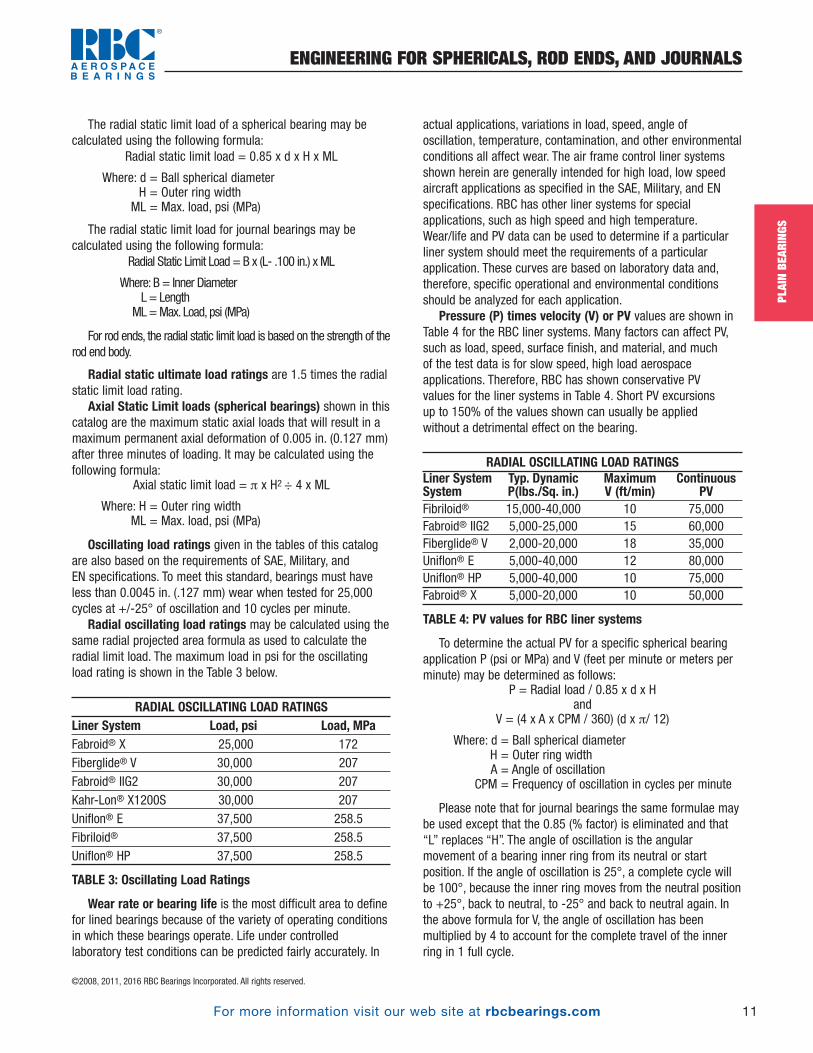
Pressure (P) times velocity (V) or PV values are shown inTable 4 for the RBC liner systems. Many factors can affect PV,such as load, speed, surface finish, and material, and much of the test data is for slow speed, high load aerospaceapplications. Therefore, RBC has shown conservative PV values for the liner systems in Table 4. Short PV excursions up to 150% of the values shown can usually be applied without a detrimental effect on the bearing.
RADIAL OSCILLATING LOAD RATINGSLiner System Typ. Dynamic Maximum ContinuousSystem P(lbs./Sq. in.) V (ft/min) PVFibriloid® 15,000-40,000 10 75,000Fabroid® IIG2 5,000-25,000 15 60,000Fiberglide® V 2,000-20,000 18 35,000Uniflon® E 5,000-40,000 12 80,000Uniflon® HP 5,000-40,000 10 75,000Fabroid® X 5,000-20,000 10 50,000
TABLE 4: PV values for RBC liner systems
To determine the actual PV for a specific spherical bearingapplication P (psi or MPa) and V (feet per minute or meters perminute) may be determined as follows:
P = Radial load / 0.85 x d x Hand
V = (4 x A x CPM / 360) (d x π/ 12)
Where: d = Ball spherical diameterH = Outer ring widthA = Angle of oscillation
CPM = Frequency of oscillation in cycles per minute
Please note that for journal bearings the same formulae maybe used except that the 0.85 (% factor) is eliminated and that“L” replaces “H”. The angle of oscillation is the angularmovement of a bearing inner ring from its neutral or startposition. If the angle of oscillation is 25°, a complete cycle willbe 100°, because the inner ring moves from the neutral positionto +25°, back to neutral, to -25° and back to neutral again. Inthe above formula for V, the angle of oscillation has beenmultiplied by 4 to account for the complete travel of the innerring in 1 full cycle.
PB_007_017_8-29-16_Pln_007_017.qxd 8/30/16 10:47 AM Page 11

For more information visit our web site at rbcbearings.com
ENGINEERING FOR SPHERICALS, ROD ENDS, AND JOURNALS
12
PLAI
N BE
ARIN
GS
©2008, 2011, 2016 RBC Bearings Incorporated. All rights reserved.
.006
.005
.004
.003
.002
.001
0 50 100 150 200 250 300LIFE CYCLES x 1000- ± 25° OSCILLATION @ 5-20 CPM
WEA
R-IN
CHES
30 KSI @ MINUS 10°F
AS81820 LIMITS38 KSI @ 70°F
20 KSI (70° to 350°F)
40 KSI (70° to 350°F)
.006
.005
.004
.003
.002
.001
0 50 100 150 200 250 300LIFE CYCLES x 1000- ± 25° OSCILLATION @ 5-20 CPM
WEA
R-IN
CHES
AS8942 LIMITS38 KSI @ 70°F
30 KSI @ 70°F
20 KSI (70° to 150°F)
10 KSI (70° to 150°F)
25 KSI (70° to 150°F)
Surface velocity of self-lubricated bearings is limited tomoderate speeds because the liner systems are not thermallyconductive, and the generated heat must be allowed todissipate. Applications with intermittent high speed areacceptable, if the duty cycle or fluid environments allows for adequate heat dissipation.
Wear rates for the RBC liner systems are shown in Figures 7and 8 below.
FIGURE 7: Typical wear rate for Uniflon® E and Fibriloid® liner
FIGURE 8: Typical wear rate for Fiberglide® V, Fabroid® IIG2
Surface Texture and Hardness of Mating Surfaces —For maximum life on journal bearings, the shaft on which the bearing runs should have a minimum hardness of Rockwell C 40 and a maximum surface texture of 8 RMS. Tables 5 and 6 show the average reductions in life for surfacetexture and material hardness.
Surface Texture (RMS) Life Factor4-10 1.00
16 0.7532 0.40
TABLE 5: Life factor reduction due to surface texture
Hardness Rc Life Factor50 1.0040 0.6030 0.40
TABLE 6: Life factor reduction due to hardness
Table 7 gives maximum surface velocities for the standardRBC liner systems operating in dry environments.
Max. Surface Velocity, ft/minLiner System @5000 psi @100 psiFiberglide® V 15 600Fabroid® IIG2 12 500Uniflon® E 8 200Fibriloid® 5 150
Max. Surface Velocity, m/minLiner System @34,500 kPa @690 kPaFiberglide® V 4.6 182.9Fabroid® IIG2 3.7 152.4Uniflon® E 2.5 75Fibriloid® 1.5 45
TABLE 7: Surface velocity limits for dry bearings
PB_007_017_8-29-16_Pln_007_017.qxd 8/30/16 10:47 AM Page 12

For more information visit our web site at rbcbearings.com
ENGINEERING FOR SPHERICALS, ROD ENDS, AND JOURNALS
13
PLAI
N BE
ARIN
GS
©2008, 2011, 2016 RBC Bearings Incorporated. All rights reserved.
Operating temperature capabilities vary among linersystems and are affected by environmental conditions.Extremely low temperatures cause the coefficient of friction torise and wear rates to increase. High speed operation or highloads will increase the bearing temperature above the ambienttemperature. Fluids may lower operating temperature, but theymay also be more aggressive at high temperatures. The metalcomponent material of the bearing must also be consideredwhen operating at extreme temperature. For example, analuminum backed bearing should not be used in applicationsabove 250°F (121°C). Table 8 lists the continuous operatingtemperature ranges for RBC liner systems in an air environmentand under moderate load (5000 psi or 34,500 kPa). Load ratingsof bearings should be derated for applications operating atelevated temperatures.
OPERATING TEMPERATURE RANGES
Liner System °F °CFiberglide® V -320 to +300 -195 to +150Fabroid® IIG2 -320 to +450 -195 to +230Uniflon® E -320 to +450 -195 to +230Fibriloid® -320 to +450 -195 to +230Fabroid® X -320 to +600 -195 to +300Uniflon® HP -65 to +325 -55 to +165Kahr-Lon® X1200S -65 to +325 -55 to +165
TABLE 8: Operating temperature ranges under 5000 psi(34.5 MPa) radial load
Coefficient of friction for a spherical bearing is:
µ = Torque/ (Ball Spherical Radius x Load)
For a journal bearing, the shaft radius is substituted for theball spherical radius in the above formula. The coefficient willvary depending on the liner system, and it is also affected byload and temperature. It should be noted that self-lubricatingbearings require a break-in period to start the lubricationprocess. Typically the coefficient of friction will decrease by50% after break-in. Figure 9 shows the effect of load on thecoefficient of friction for the RBC liner systems. Figure 10 showsthe effect of temperature on the coefficient of friction.
FIGURE 9: Effect of load on the coefficient of friction
FIGURE 10: Coefficient of friction vs. temperature
Fabroid X data points added0.14
0.12
0.10
0.08
0.06
0.04
0.02
00 5 10 15 20 25 30 35 40 45
LOADS (KSI)
Coef
ficei
nts
of F
rictio
n
Fibriloid and Uniflon E
Fiberglide V
Fabroid II/IIG2
Uniflon HP
Fabroid X
PB_007_017_8-29-16_Pln_007_017.qxd 8/30/16 10:47 AM Page 13

For more information visit our web site at rbcbearings.com
ENGINEERING FOR SPHERICALS, ROD ENDS, AND JOURNALS
14
PLAI
N BE
ARIN
GS
©2008, 2011, 2016 RBC Bearings Incorporated. All rights reserved.
Fluid compatibility and contamination will affect wear rateor bearing life. RBC liner systems have been extensively testedin many environments. Testing includes both applicationqualification tests and SAE tests for MS qualifications. Thethermoset resins and adhesives used by RBC are essentiallyimpervious to the fluids encountered in aerospace applications.The following is a partial list of the fluids in which various RBCliner systems have been tested:
AS1241 Phosphate Ester Hyrdaulic FluidASTM D471MIL-PRF-7808 Lubricating OilMIL PRF-5606 Hydraulic OilMIL-PRF-83282 Hydraulic OilAMS1424 De-Icing FluidMIL-PRF-5624 Turbine FuelMIL-PRF-23699MIL-PRF-6085SKYDROL 500 BMethanol1-1-1 TrichloroethaneWaterMIL-PRF-87937 Aerospace DetergentMIL-STD-810, Salt SprayMIL-STD-810, FungusSand and Dust Liquid Nitrogen, N2VacuumAerospace Cleaning Detergents
While these fluids will not attack the liner system, it shouldbe noted that fluids may increase the wear rate of the liners.The fluids tend to flush out the PTFE particles that coat themating surfaces. This interferes with the natural PTFE self-lubricating process and thus increases wear.
Solid particle contaminants of dirt and dust tend to becomeimbedded into the relatively soft liner surfaces. If the particlecontamination is abrasive, it will begin to wear the matingsurface of the ball or shaft. Should contamination be particularlysevere, bearings can be provided with hard coatings or seals.
PB_007_017_8-29-16_Pln_007_017.qxd 8/30/16 10:47 AM Page 14

For more information visit our web site at rbcbearings.com
ENGINEERING FOR SPHERICALS, ROD ENDS, AND JOURNALS
15
PLAI
N BE
ARIN
GS
©2008, 2011, 2016 RBC Bearings Incorporated. All rights reserved.
BEARING INSTALLATIONProper installation of plain bearings will help to assure that
maximum life will be obtained. Improper assembly may damageliners, cause excessive loading, or in other ways decrease theuseful life of the bearing.
Housing fit for a metal-to-metal spherical bearing isrecommended to be from 0.0000 to 0.0010 in. (.025mm) loose.Press fitting these bearings into the housing may remove theinitial radial clearance causing the bearings to lock up. Thermalexpansions of materials must also be considered
Housing fit for a self-lubricating spherical bearing isrecommended to be from 0.0002 in. tight to 0.0008 in. loose or0.005mm tight to 0.020mm loose for a metric bearing. Forexample, a bearing having an outside diameter of 1.0000 in. to0.9995 in. should be inserted into a housing having an insidediameter of 0.9998 in. to 1.0003 in. A bearing having an outsidediameter of 25.000mm to 24.987mm should be inserted into ahousing having an inside diameter of 24.995mm to 25.020mm.Where tighter than recommended fits are used, the bearing willbecome radialy pre-loaded. This will result in increased bearingstarting torque. The recommended fit is applicable for bearingswith outside diameters up to 2.500 in. (63.5mm). For largerbearings or for special materials or applications consult theappropriate RBC Aerospace Bearings sales engineer.
An increase in pre-load torque is beneficial in high frequencyvibration conditions and in solid particle contaminatedenvironments. Pre-load torque is not additive to the frictionaltorque due to an applied load.
The housing fit for journal bearings should be 0.0005 in.(0.013 mm) tight to 0.0020 in. (0.050 mm) tight for bearings upto 4.0 in. or (100mm) in diameter. Care must be taken inselecting housing and shaft diameters to assure that there isnot an interference fit between the bearing bore and the shaft.The following formulas may be used to determine the reductionin bore diameter due to a tight housing fit:
Case 1. Different housing and bearing materials
Case 2. Same housing and shaft material
Where: a = bearing boreb = housing bore
d1 = Poission’s ratio for bearing materiald2 = Poission’s ratio for housing materialya = amount of reduction in bore size� = amount of interference fitE1 = modulus of elasticity of bearing materialE2 = modulus of elasticity of housing material
In both of the above cases a massive housing is assumed.
Dissimilar materials must be considered when operating at low or high temperatures or when a large bearing is beingused. When the materials for the housing and bearing backingor the shaft and the inner ring are not the same, loss of fit in the housing and contraction of the bearing bore must beconsidered. Calculations of loss of fit and bearing borecontraction are necessary to prevent the bearings from turningin the housing and also to prevent a tight fit between thebearing and the shaft.
To determine how much a housing bore or a bearingdiameter changes in size as a result of temperature change, use the following formula:
�= � x � x �T
Where: � = change in diameter� = coefficient of thermal expansion� = housing or bearing diameter
�T = temperature change
Contraction of the bearing may be calculated using theformulas shown above in the housing fits for journal bearingssection.ya =
2Dba( )
ba( )2 b
a( )2+ 1 + k2 – 1[ ] [ ]
ya = Dab( )
K2 = constant = (1 + d2) – d1E1
E2
PB_007_017_8-29-16_Pln_007_017.qxd 8/30/16 10:47 AM Page 15

For more information visit our web site at rbcbearings.com
ENGINEERING FOR SPHERICALS, ROD ENDS, AND JOURNALS
16
PLAI
N BE
ARIN
GS
©2008, 2011, 2016 RBC Bearings Incorporated. All rights reserved.
Shaft fit for metal-to-metal spherical bearings is not tobe less than 0.0005 in. (0.013mm) loose at operatingtemperature.
Shaft fit for self-lubricating spherical bearings withunlined bores is recommended to be 0.0001 in. to 0.0010 in.loose (0.003mm to 0.025mm loose) in standard applications.For example, a bearing having a bore diameter of 0.7495 in. to0.7500 in. should be assembled onto a shaft having an outsidediameter of 0.7494 in. to 0.7490 in. Similarly a bearing having abore diameter of 20.003mm to 19.991mm should be assembledonto a shaft having an outside diameter 19.978mm to19.988mm. This is applicable for bearings, which have unlinedbores and with bore diameters up to 1.500 in. (38mm). If thebore of the bearing inner ring is lined a shaft fit of 0.0000 in. to 0.0015 in. loose (0.000mm to 0.038mm loose for metricbearings) is recommended. For special applications or forbearings with bores larger than 1.500 in. (38mm) consult RBCengineering.
Shaft fits for journal bearings, where slow oscillating or low rotational speeds are coupled with high loads, arerecommended to be from 0.0005 in. (0.013 mm) loose to0.0030 in. (0.76 mm) loose. Contraction of the bearing borecaused by a heavy press fit in the housing or by thermalcontraction must be considered. See housing fit above.
BEARING INSTALLATIONA hammer or other mechanism that induces a shock load on
the bearing should never be used. The corner of the housingbore should have a radius or chamfer that has a smoothtransition to the housing bore. The bearing should be aligned tothe bore and a constant steady force applied to seat thebearing. A tool, which pilots on the bearing bore and whichapplies load to the outer ring face, is recommended. SeeFigures 11 and 12.
FIGURE 11: Spherical bearing assembly tool
FIGURE 12: Journal bearing assembly tool
Bearing installations per the specification NAS 0331 arerecommended.
PB_007_017_8-29-16_Pln_007_017.qxd 8/30/16 10:47 AM Page 16
For more information visit our web site at rbcbearings.com
ENGINEERING FOR SPHERICALS, ROD ENDS, AND JOURNALS
17
PLAI
N BE
ARIN
GS
©2008, 2011, 2016 RBC Bearings Incorporated. All rights reserved.
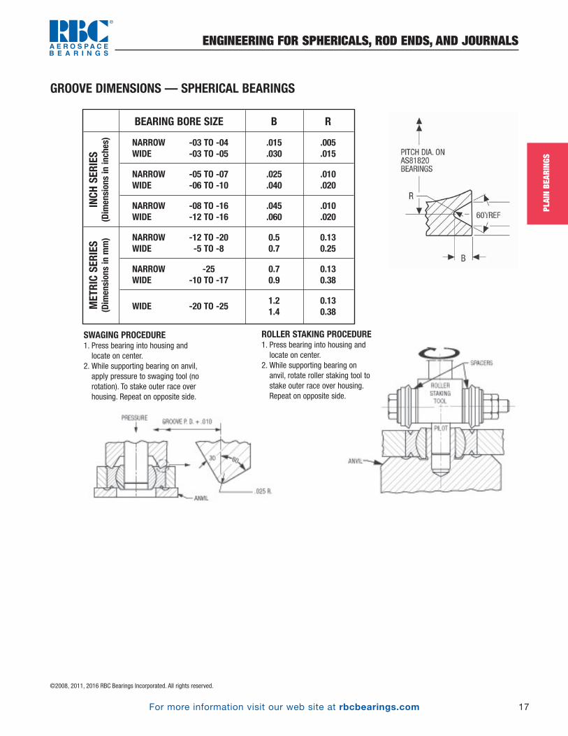
GROOVE DIMENSIONS — SPHERICAL BEARINGS
BEARING BORE SIZE B R
NARROW -03 TO -04 .015 .005WIDE -03 TO -05 .030 .015
NARROW -05 TO -07 .025 .010WIDE -06 TO -10 .040 .020
NARROW -08 TO -16 .045 .010WIDE -12 TO -16 .060 .020
NARROW -12 TO -20 0.5 0.13WIDE -5 TO -8 0.7 0.25
NARROW -25 0.7 0.13WIDE -10 TO -17 0.9 0.38
WIDE -20 TO -251.2 0.131.4 0.38
INCH SERIES
(Dimensions in inches)
METRIC SERIES
(Dimensions in mm)
SWAGING PROCEDURE1. Press bearing into housing and
locate on center.2. While supporting bearing on anvil,
apply pressure to swaging tool (norotation). To stake outer race overhousing. Repeat on opposite side.
ROLLER STAKING PROCEDURE1. Press bearing into housing and
locate on center.2. While supporting bearing on
anvil, rotate roller staking tool tostake outer race over housing.Repeat on opposite side.
PB_007_017_8-29-16_Pln_007_017.qxd 8/30/16 10:47 AM Page 17
©2008, 2011, 2016 RBC Bearings Incorporated. All rights reserved.
For more information visit our web site at rbcbearings.com18
SPHE
RICA
LBE
ARIN
GS
RBC Spherical Bearings
GENERAL FEATURES AND TECHNICAL SPECIFICATIONS
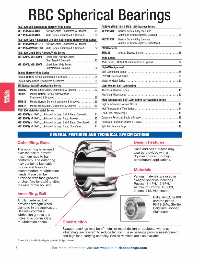
Outer Ring, Race
The outer ring is swagedover the ball to providemaximum race to ballconformity. The outer ringmay contain a lubricationgroove and holes toaccommodate re-lubricationneeds. Race can befurnished with face groovesor chamfers for staking eitherthe race or the housing.
Materials
Various materials are used inswaged spherical bearings.Races: 17-4PH, 15-5PH,Aluminum Bronze, AISI303,Inconel-718. Aluminum.
Balls: 440C, 52100chrome plated,PH13-8Mo, Stellite,Beryllium Copper,Aluminum.
Design Features
Race and ball surfaces mayalso be provided with a dry-film lubricant for hightemperature applications.
Construction
Swaged bearings may be of metal-to-metal design or equipped with a selflubricating liner system to reduce friction. These bearings provide misalignmentand high load carrying capacity. Sealed versions are also available.
Inner Ring, Ball
A fully hardened ballprovides strength whenclamped in the application.Ball may contain alubrication groove andholes to accommodate re-lubrication needs.
AS81820 Self-Lubricating Narrow/Wide SeriesMS14104/MS14101 Narrow Series, Chamfered & Grooved . . . . . 19MS14102/MS14103 Wide Series, Chamfered & Grooved . . . . . . . 20
AS81820 Type A Extended Life Self-Lubricating Narrow/Wide SeriesMS14104A/MS14101A Narrow Series, Chamfered & Grooved . . . . . 21MS14102A/MS14103A Wide Series, Chamfered & Grooved . . . . . . . 22
AS81820 Lined Bore Narrow/Wide SeriesM81820/4, M81820/1 Lined Bore, Narrow Series,
Chamfered & Grooved . . . . . . . . . . . . . . . . . 23M81820/2, M81820/3 Lined Bore, Wide Series,
Chamfered & Grooved . . . . . . . . . . . . . . . . . 24
Sealed Narrow/Wide SeriesSealed, Narrow Series, Chamfered & Grooved . . . . . . . . . . . . . . . . . . . 25Sealed, Wide Series, Chamfered & Grooved . . . . . . . . . . . . . . . . . . . . . 26
EN Standards/Self-Lubricating SeriesEN2022 Metric, Light Series, Chamfered & Grooved . . . . . . . . . . . . 27EN2023 Metric, Normal Series, Narrow/Wide,
Chamfered & Grooved . . . . . . . . . . . . . . . . . . . . . . . . . . . . 28EN4613 Metric, Narrow Series, Chamfered & Grooved. . . . . . . . . . . 29EN4614 Metric, Wide Series, Chamfered & Grooved . . . . . . . . . . . . 30
AS81936 Metal-to-Metal SeriesM81936/1( ) BeCu, Lubricated through Ball & Race, Grooved . . . . . . 31M81936/1( )R BeCu, Lubricated through Race, Grooved . . . . . . . . . . . 32M81936/2( ) BeCu, Lubricated through Ball & Race, Chamfered . . . . 33M81936/2( )R BeCu, Lubricated through Race, Chamfered . . . . . . . . . 34
AS8976 (MS21154 & MS21155) Narrow Series
MS21154B Narrow Series, Alloy Steel and Aluminum Bronze Options, Grooved . . . . . . . . . . . . . . 35
MS21155B Narrow Series, Alloy Steel and Aluminum Bronze Options, Chamfered . . . . . . . . . . . . . 35
EN Standards
EN2335 Metric, Swaged Series . . . . . . . . . . . . . . . . . . . . . . . . . 36
Wide Series
Wide Series, CRES & Aluminum Bronze Options . . . . . . . . . . . . . . . . . . 37
High-Misalignment
Self-Lubricating Series. . . . . . . . . . . . . . . . . . . . . . . . . . . . . . . . . . . . . 38
EN2501 Standard Series . . . . . . . . . . . . . . . . . . . . . . . . . . . . . . . . . . . 39
Metal-to-Metal Series . . . . . . . . . . . . . . . . . . . . . . . . . . . . . . . . . . . . . 40
Light Weight Self-Lubricating
Aluminum Narrow Series . . . . . . . . . . . . . . . . . . . . . . . . . . . . . . . . . . . 41
Aluminum Wide Series . . . . . . . . . . . . . . . . . . . . . . . . . . . . . . . . . . . . . 42
High Temperature Self-Lubricating Narrow/Wide Series
High Temperature Narrow Series . . . . . . . . . . . . . . . . . . . . . . . . . . . . . 43
High Temperature Wide Series . . . . . . . . . . . . . . . . . . . . . . . . . . . . . . . 44
Load Slot Feature Page . . . . . . . . . . . . . . . . . . . . . . . . . . . . . . . . . . . . 45
Corrosion Resistant Single V-Groove. . . . . . . . . . . . . . . . . . . . . . . . . . . 46
Corrosion Resistant Double V-Groove . . . . . . . . . . . . . . . . . . . . . . . . . . 47
Split Ball Feature Page . . . . . . . . . . . . . . . . . . . . . . . . . . . . . . . . . . . . . 48
PB_018_048_8-30-16_Pln_018_050.qxd 8/30/16 11:00 AM Page 18
For more information visit our web site at rbcbearings.com
SELF-LUBRICATED SPHERICAL BEARINGS
19
SPHE
RICA
LBE
ARIN
GS
©2008, 2011, 2016 RBC Bearings Incorporated. All rights reserved.
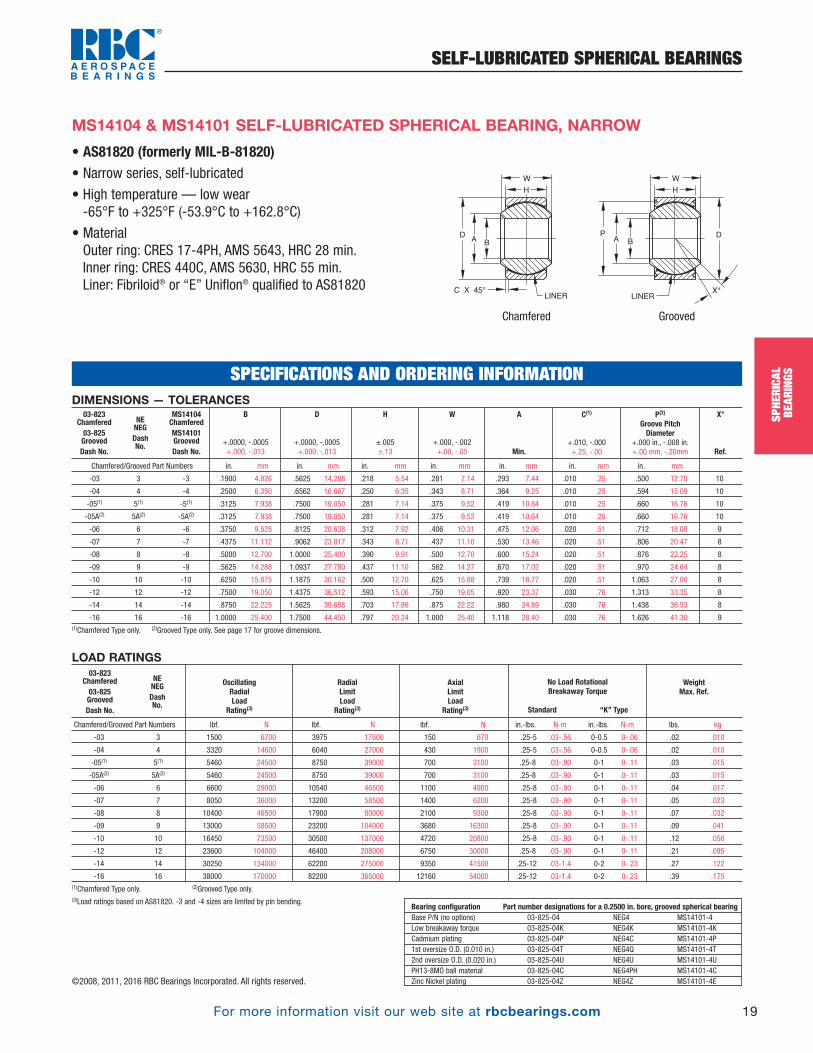
• AS81820 (formerly MIL-B-81820)• Narrow series, self-lubricated
• High temperature — low wear-65°F to +325°F (-53.9°C to +162.8°C)
• MaterialOuter ring: CRES 17-4PH, AMS 5643, HRC 28 min.Inner ring: CRES 440C, AMS 5630, HRC 55 min.Liner: Fibriloid® or “E” Uniflon® qualified to AS81820
MS14104 & MS14101 SELF-LUBRICATED SPHERICAL BEARING, NARROW
DIMENSIONS — TOLERANCES
Chamfered/Grooved Part Numbers in. mm in. mm in. mm in. mm in. mm in. mm in. mm
-03 3 -3 .1900 4.826 .5625 14.288 .218 5.54 .281 7.14 .293 7.44 .010 .25 .500 12.70 10
-04 4 -4 .2500 6.350 .6562 16.667 .250 6.35 .343 8.71 .364 9.25 .010 .25 .594 15.09 10
-05(1) 5(1) -5(1) .3125 7.938 .7500 19.050 .281 7.14 .375 9.52 .419 10.64 .010 .25 .660 16.76 10
-05A(2) 5A(2) -5A(2) .3125 7.938 .7500 19.050 .281 7.14 .375 9.52 .419 10.64 .010 .25 .660 16.76 10
-06 6 -6 .3750 9.525 .8125 20.638 .312 7.92 .406 10.31 .475 12.06 .020 .51 .712 18.08 9
-07 7 -7 .4375 11.112 .9062 23.017 .343 8.71 .437 11.10 .530 13.46 .020 .51 .806 20.47 8
-08 8 -8 .5000 12.700 1.0000 25.400 .390 9.91 .500 12.70 .600 15.24 .020 .51 .876 22.25 8
-09 9 -9 .5625 14.288 1.0937 27.780 .437 11.10 .562 14.27 .670 17.02 .020 .51 .970 24.64 8
-10 10 -10 .6250 15.875 1.1875 30.162 .500 12.70 .625 15.88 .739 18.77 .020 .51 1.063 27.00 8
-12 12 -12 .7500 19.050 1.4375 36.512 .593 15.06 .750 19.05 .920 23.37 .030 .76 1.313 33.35 8
-14 14 -14 .8750 22.225 1.5625 39.688 .703 17.86 .875 22.22 .980 24.89 .030 .76 1.438 36.53 8
-16 16 -16 1.0000 25.400 1.7500 44.450 .797 20.24 1.000 25.40 1.118 28.40 .030 .76 1.626 41.30 9(1)Chamfered Type only. (2)Grooved Type only. See page 17 for groove dimensions.
X°
Ref.
P(2)
Groove Pitch Diameter
+.000 in., -.008 in.+.00 mm, -.20mm
C(1)
+.010, -.000 +.25, -.00
A
Min.
W
+.000, -.002 +.00, -.05
H
±.005 ±.13
D
+.0000, -.0005 +.000, -.013
B
+.0000, -.0005 +.000, -.013
03-823Chamfered03-825GroovedDash No.
NENEGDash No.
MS14104ChamferedMS14101GroovedDash No.
LOAD RATINGS
Chamfered/Grooved Part Numbers lbf. N lbf. N lbf. N in.-lbs. N-m in.-lbs. N-m lbs. kg
-03 3 1500 6700 3975 17600 150 670 .25-5 .03-.56 0-0.5 0-.06 .02 .010
-04 4 3320 14600 6040 27000 430 1900 .25-5 .03-.56 0-0.5 0-.06 .02 .010
-05(1) 5(1) 5460 24500 8750 39000 700 3100 .25-8 .03-.90 0-1 0-.11 .03 .015
-05A(2) 5A(2) 5460 24500 8750 39000 700 3100 .25-8 .03-.90 0-1 0-.11 .03 .015
-06 6 6600 29000 10540 46500 1100 4900 .25-8 .03-.90 0-1 0-.11 .04 .017
-07 7 8050 36000 13200 58500 1400 6200 .25-8 .03-.90 0-1 0-.11 .05 .023
-08 8 10400 46500 17900 80000 2100 9300 .25-8 .03-.90 0-1 0-.11 .07 .032
-09 9 13000 58500 23200 104000 3680 16300 .25-8 .03-.90 0-1 0-.11 .09 .041
-10 10 16450 73500 30500 137000 4720 20800 .25-8 .03-.90 0-1 0-.11 .12 .056
-12 12 23600 104000 46400 208000 6750 30000 .25-8 .03-.90 0-1 0-.11 .21 .095
-14 14 30250 134000 62200 275000 9350 41500 .25-12 .03-1.4 0-2 0-.23 .27 .122
-16 16 38000 170000 82200 365000 12160 54000 .25-12 .03-1.4 0-2 0-.23 .39 .175(1)Chamfered Type only. (2)Grooved Type only.(3)Load ratings based on AS81820. -3 and -4 sizes are limited by pin bending.
WeightMax. Ref.
No Load RotationalBreakaway Torque
Standard “K” Type
AxialLimitLoad
Rating(3)
RadialLimitLoad
Rating(3)
OscillatingRadialLoad
Rating(3)
03-823Chamfered03-825GroovedDash No.
NENEGDash No.
Bearing configuration Part number designations for a 0.2500 in. bore, grooved spherical bearingBase P/N (no options) 03-825-04 NEG4 MS14101-4Low breakaway torque 03-825-04K NEG4K MS14101-4KCadmium plating 03-825-04P NEG4C MS14101-4P1st oversize O.D. (0.010 in.) 03-825-04T NEG4Q MS14101-4T2nd oversize O.D. (0.020 in.) 03-825-04U NEG4U MS14101-4UPH13-8MO ball material 03-825-04C NEG4PH MS14101-4CZinc Nickel plating 03-825-04Z NEG4Z MS14101-4E
SPECIFICATIONS AND ORDERING INFORMATION
A B
LINER
G
W
H
C X 45° X°
PDA
B
LINER
W
H
D
Chamfered Grooved
PB_018_048_8-30-16_Pln_018_050.qxd 8/30/16 11:00 AM Page 19

For more information visit our web site at rbcbearings.com
SELF-LUBRICATED SPHERICAL BEARINGS
20
SPHE
RICA
LBE
ARIN
GS
©2008, 2011, 2016 RBC Bearings Incorporated. All rights reserved.
• AS81820 (formerly MIL-B-81820)• Wide series, self-lubricated
• High temperature — low wear-65°F to +325°F (-53.9°C to +162.8°C)
• MaterialOuter ring: CRES 17-4PH, AMS 5643, HRC 28 min.Inner ring: CRES 440C, AMS 5630, HRC 55 min.Liner: Fibriloid® or “E” Uniflon® qualified to AS81820
MS14102 & MS14103 SELF-LUBRICATED SPHERICAL BEARING, WIDE
DIMENSIONS — TOLERANCES
Chamfered/Grooved Part Numbers in. mm in. mm in. mm in. mm in. mm in. mm in. mm
-03 3 -3 .1900 4.826 .6250 15.875 .327 8.31 .437 11.10 .300 7.62 .010 0.25 .563 14.30 15
-04 4 -4 .2500 6.350 .6250 15.875 .327 8.31 .437 11.10 .300 7.62 .010 0.25 .563 14.30 15
-05 5 -5 .3125 7.938 .6875 17.462 .317 8.05 .437 11.10 .360 9.14 .010 0.25 .625 15.88 14
-06 6 -6 .3750 9.525 .8125 20.638 .406 10.31 .500 12.70 .466 11.84 .020 0.51 .712 18.08 8
-07A(2) -7A(2) -7A(2) .4375 11.112 .9062 23.017 .442 11.23 .562 14.27 .537 13.64 .020 0.51 .806 20.47 10
-07 7 -7 .4375 11.112 .9375 23.812 .442 11.23 .562 14.27 .537 13.64 .020 0.51 .837 21.26 10
-08 8 -8 .5000 12.700 1.0000 25.400 .505 12.83 .625 15.88 .607 15.42 .020 0.51 .900 22.86 9
-09 9 -9 .5625 14.288 1.1250 28.575 .536 13.61 .687 17.45 .721 18.31 .020 0.51 1.025 26.04 10
-10 10 -10 .6250 15.875 1.1875 30.162 .567 14.40 .750 19.05 .747 18.97 .020 0.51 1.087 27.61 12
-12 12 -12 .7500 19.050 1.3750 34.925 .630 16.00 .875 22.22 .845 21.46 .030 0.76 1.251 31.78 13
-14 14 -14 .8750 22.225 1.6250 41.275 .755 19.18 .875 22.22 .995 25.27 .030 0.76 1.501 38.13 6
-16 16 -16 1.0000 25.400 2.1250 53.975 1.005 25.53 1.375 34.92 1.269 32.23 .030 0.76 2.001 50.83 12(1)Chamfered Type only. (2)Grooved Type only. See page 17 for groove dimensions.
X°
Ref.
P(2)
Groove PitchDiameter
+.000 in., -.008 in.+.00 mm, -.20mm
C(1)
+.010, -.000 +.25, -.00
A
Min.
W
+.000, -.002 +.00, -.05
H
±.005 ±.13
D
+.0000, -.0005 +.000, -.013
B
+.0000, -.0005 +.000, -.013
03-824Chamfered03-826GroovedDash No.
WEWEGDash No.
MS14102ChamferedMS14103GroovedDash No.
LOAD RATINGS
Chamfered/Grooved Part Numbers lbf. N lbf. N lbf. N in.-lbs. N-m in.-lbs. N-m lbs. kg
-03 3 4900 21600 2500 11100 1770 7800 .25-5 .03-.56 0.05 0-.06 .031 .014
-04 4 4900 21600 5500 24400 1770 7800 .25-5 .03-.56 0.05 0-.06 .031 .014
-05 5 6050 27000 9400 41800 1640 7350 .25-8 .03-.90 0.10 0-.11 .035 .016
-06 6 8310 36500 13700 60900 2630 11600 .25-8 .03-.90 0.10 0-.11 .060 .027
-07A(2) 7A(2) 11750 52000 19700 87600 3650 16300 .25-8 .03-.90 0.10 0-.11 .080 .036
-07 7 11750 52000 20700 92000 3650 16300 .25-8 .03-.90 0.10 0-.11 .080 .036
-08 8 14950 65500 21400 95000 4970 22000 .25-8 .03-.90 0.10 0-.11 .100 .045
-09 9 18100 80000 26600 118000 5370 24000 .25-8 .03-.90 0.10 0-.11 .135 .061
-10 10 20250 90000 29000 128500 6130 27500 .25-8 .03-.90 0.10 0-.11 .160 .072
-12 12 26200 116000 37000 164500 7730 34500 .25-8 .03-.90 0.10 0-.11 .240 .110
-14 -14 33600 150000 65200 290000 10800 48000 .25-12 .03-1.4 0.20 0-.23 .350 .160
-16 16 56250 250000 104000 462500 19300 86500 .25-12 .03-1.4 0.20 0-.23 .970 .440(1)Chamfered Type only. (2)Grooved Type only.(3)Load ratings based on AS81820. -3 and -4 sizes are limited by pin bending.
WeightMax. Ref.
No Load RotationalBreakaway Torque
Standard “K” Type
AxialLimitLoad
Rating(3)
RadialLimitLoad
Rating(3)
OscillatingRadialLoad
Rating(3)
03-824Chamfered03-826GroovedDash No.
WEWEGDash No.
Bearing configuration Part number designations for a 0.2500 in. bore, grooved spherical bearingBase P/N (no options) 03-826-04 WEG4 MS14103-4Low breakaway torque 03-826-04K WEG4K MS14103-4KCadmium plating 03-826-04P WEG4C MS14103-4P1st oversize O.D. (0.010 in.) 03-826-04T WEG4Q MS14103-4T2nd oversize O.D. (0.020 in.) 03-826-04U WEG4U MS14103-4UPH13-8MO ball material 03-826-04C WEG4PH MS14103-4CZinc Nickel plating 03-826-04Z WEG4Z MS14103-4Z
SPECIFICATIONS AND ORDERING INFORMATION
A B
LINER
W
H
C X 45° X°
PDA
B
LINER
W
H
D
Chamfered Grooved
PB_018_048_8-30-16_Pln_018_050.qxd 8/30/16 11:00 AM Page 20
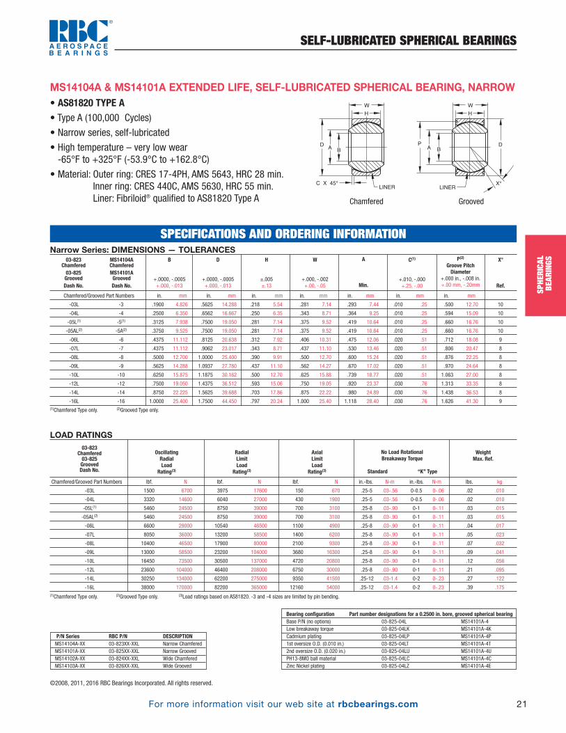
For more information visit our web site at rbcbearings.com
SELF-LUBRICATED SPHERICAL BEARINGS
21
SPHE
RICA
LBE
ARIN
GS
©2008, 2011, 2016 RBC Bearings Incorporated. All rights reserved.
• AS81820 TYPE A• Type A (100,000 Cycles)
• Narrow series, self-lubricated
• High temperature – very low wear -65°F to +325°F (-53.9°C to +162.8°C)
• Material: Outer ring: CRES 17-4PH, AMS 5643, HRC 28 min.Inner ring: CRES 440C, AMS 5630, HRC 55 min.Liner: Fibriloid® qualified to AS81820 Type A
MS14104A & MS14101A EXTENDED LIFE, SELF-LUBRICATED SPHERICAL BEARING, NARROW
Narrow Series: DIMENSIONS — TOLERANCES
Chamfered/Grooved Part Numbers in. mm in. mm in. mm in. mm in. mm in. mm in. mm
-03L -3 .1900 4.826 .5625 14.288 .218 5.54 .281 7.14 .293 7.44 .010 .25 .500 12.70 10
-04L -4 .2500 6.350 .6562 16.667 .250 6.35 .343 8.71 .364 9.25 .010 .25 .594 15.09 10
-05L(1) -5(1) .3125 7.938 .7500 19.050 .281 7.14 .375 9.52 .419 10.64 .010 .25 .660 16.76 10
-05AL(2) -5A(2) .3750 9.525 .7500 19.050 .281 7.14 .375 9.52 .419 10.64 .010 .25 .660 16.76 10
-06L -6 .4375 11.112 .8125 20.638 .312 7.92 .406 10.31 .475 12.06 .020 .51 .712 18.08 9
-07L -7 .4375 11.112 .9062 23.017 .343 8.71 .437 11.10 .530 13.46 .020 .51 .806 20.47 8
-08L -8 .5000 12.700 1.0000 25.400 .390 9.91 .500 12.70 .600 15.24 .020 .51 .876 22.25 8
-09L -9 .5625 14.288 1.0937 27.780 .437 11.10 .562 14.27 .670 17.02 .020 .51 .970 24.64 8
-10L -10 .6250 15.875 1.1875 30.162 .500 12.70 .625 15.88 .739 18.77 .020 .51 1.063 27.00 8
-12L -12 .7500 19.050 1.4375 36.512 .593 15.06 .750 19.05 .920 23.37 .030 .76 1.313 33.35 8
-14L -14 .8750 22.225 1.5625 39.688 .703 17.86 .875 22.22 .980 24.89 .030 .76 1.438 36.53 8
-16L -16 1.0000 25.400 1.7500 44.450 .797 20.24 1.000 25.40 1.118 28.40 .030 .76 1.626 41.30 9(1)Chamfered Type only. (2)Grooved Type only.
X°
Ref.
P(2)
Groove PitchDiameter
+.000 in., -.008 in.+.00 mm, -.20mm
C(1)
+.010, -.000 +.25, -.00
A
Min.
W
+.000, -.002 +.00, -.05
H
±.005 ±.13
D
+.0000, -.0005 +.000, -.013
B
+.0000, -.0005 +.000, -.013
03-823 Chamfered03-825GroovedDash No.
MS14104AChamferedMS14101AGroovedDash No.
LOAD RATINGS
Chamfered/Grooved Part Numbers lbf. N lbf. N lbf. N in.-lbs. N-m in.-lbs. N-m lbs. kg
-03L 1500 6700 3975 17600 150 670 .25-5 .03-.56 0-0.5 0-.06 .02 .010
-04L 3320 14600 6040 27000 430 1900 .25-5 .03-.56 0-0.5 0-.06 .02 .010
-05L(1) 5460 24500 8750 39000 700 3100 .25-8 .03-.90 0-1 0-.11 .03 .015
-05AL(2) 5460 24500 8750 39000 700 3100 .25-8 .03-.90 0-1 0-.11 .03 .015
-06L 6600 29000 10540 46500 1100 4900 .25-8 .03-.90 0-1 0-.11 .04 .017
-07L 8050 36000 13200 58500 1400 6200 .25-8 .03-.90 0-1 0-.11 .05 .023
-08L 10400 46500 17900 80000 2100 9300 .25-8 .03-.90 0-1 0-.11 .07 .032
-09L 13000 58500 23200 104000 3680 16300 .25-8 .03-.90 0-1 0-.11 .09 .041
-10L 16450 73500 30500 137000 4720 20800 .25-8 .03-.90 0-1 0-.11 .12 .056
-12L 23600 104000 46400 208000 6750 30000 .25-8 .03-.90 0-1 0-.11 .21 .095
-14L 30250 134000 62200 275000 9350 41500 .25-12 .03-1.4 0-2 0-.23 .27 .122
-16L 38000 170000 82200 365000 12160 54000 .25-12 .03-1.4 0-2 0-.23 .39 .175(1)Chamfered Type only. (2)Grooved Type only. (3)Load ratings based on AS81820. -3 and -4 sizes are limited by pin bending.
WeightMax. Ref.
No Load RotationalBreakaway Torque
Standard “K” Type
AxialLimitLoad
Rating(3)
RadialLimitLoad
Rating(3)
OscillatingRadialLoad
Rating(3)
03-823 Chamfered03-825GroovedDash No.
Bearing configuration Part number designations for a 0.2500 in. bore, grooved spherical bearingBase P/N (no options) 03-825-04L MS14101A-4Low breakaway torque 03-825-04LK MS14101A-4KCadmium plating 03-825-04LP MS14101A-4P1st oversize O.D. (0.010 in.) 03-825-04LT MS14101A-4T2nd oversize O.D. (0.020 in.) 03-825-04LU MS14101A-4UPH13-8MO ball material 03-825-04LC MS14101A-4CZinc Nickel plating 03-825-04LZ MS14101A-4E
SPECIFICATIONS AND ORDERING INFORMATION
A B
LINER
W
H
C X 45° X°
PDA
B
LINER
W
H
D
Chamfered Grooved
P/N Series RBC P/N DESCRIPTIONMS14104A-XX 03-823XX-XXL Narrow ChamferedMS14101A-XX 03-825XX-XXL Narrow GroovedMS14102A-XX 03-824XX-XXL Wide ChamferedMS14103A-XX 03-826XX-XXL Wide Grooved
PB_018_048_8-30-16_Pln_018_050.qxd 8/30/16 11:00 AM Page 21
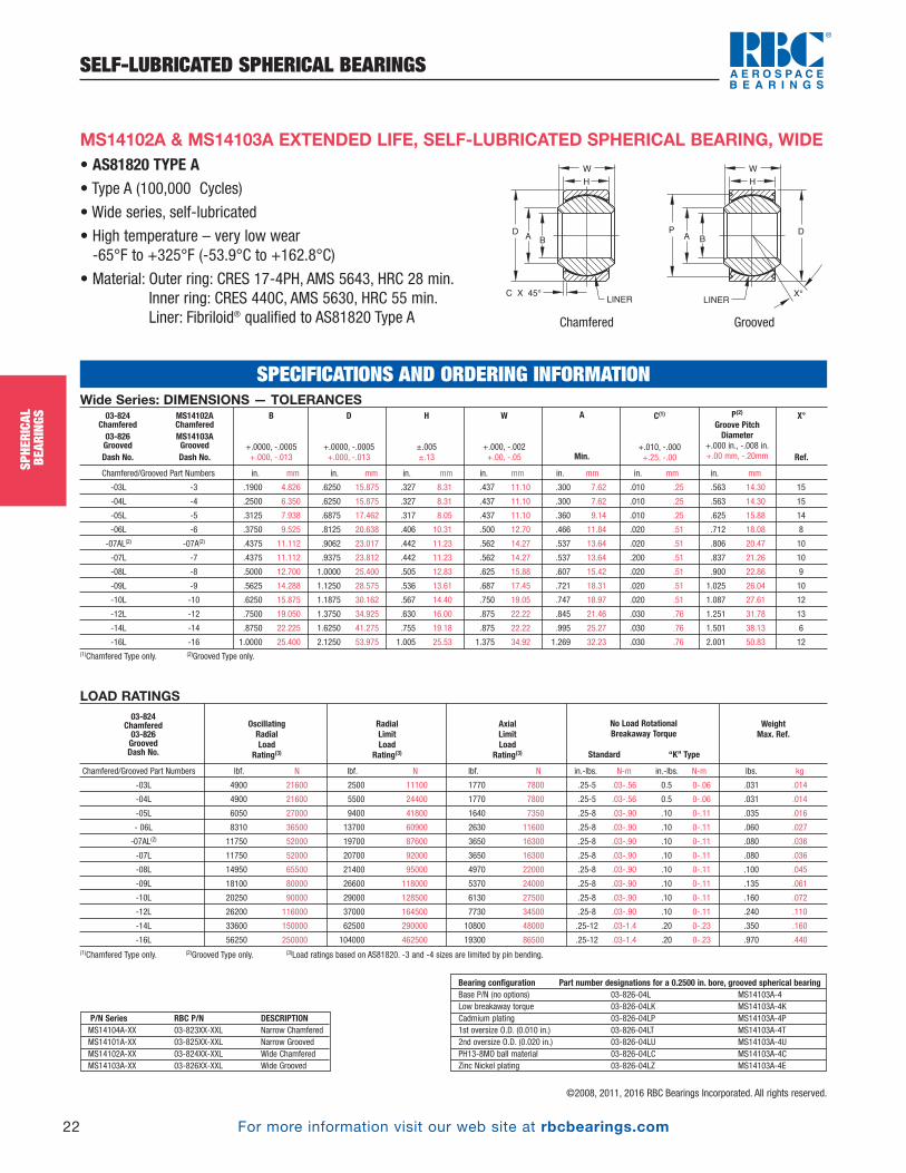
For more information visit our web site at rbcbearings.com
SELF-LUBRICATED SPHERICAL BEARINGS
22
SPHE
RICA
LBE
ARIN
GS
©2008, 2011, 2016 RBC Bearings Incorporated. All rights reserved.
• AS81820 TYPE A• Type A (100,000 Cycles)
• Wide series, self-lubricated
• High temperature – very low wear -65°F to +325°F (-53.9°C to +162.8°C)
• Material: Outer ring: CRES 17-4PH, AMS 5643, HRC 28 min.Inner ring: CRES 440C, AMS 5630, HRC 55 min.Liner: Fibriloid® qualified to AS81820 Type A
MS14102A & MS14103A EXTENDED LIFE, SELF-LUBRICATED SPHERICAL BEARING, WIDE
Wide Series: DIMENSIONS — TOLERANCES
Chamfered/Grooved Part Numbers in. mm in. mm in. mm in. mm in. mm in. mm in. mm
-03L -3 .1900 4.826 .6250 15.875 .327 8.31 .437 11.10 .300 7.62 .010 .25 .563 14.30 15
-04L -4 .2500 6.350 .6250 15.875 .327 8.31 .437 11.10 .300 7.62 .010 .25 .563 14.30 15
-05L -5 .3125 7.938 .6875 17.462 .317 8.05 .437 11.10 .360 9.14 .010 .25 .625 15.88 14
-06L -6 .3750 9.525 .8125 20.638 .406 10.31 .500 12.70 .466 11.84 .020 .51 .712 18.08 8
-07AL(2) -07A(2) .4375 11.112 .9062 23.017 .442 11.23 .562 14.27 .537 13.64 .020 .51 .806 20.47 10
-07L -7 .4375 11.112 .9375 23.812 .442 11.23 .562 14.27 .537 13.64 .200 .51 .837 21.26 10
-08L -8 .5000 12.700 1.0000 25.400 .505 12.83 .625 15.88 .607 15.42 .020 .51 .900 22.86 9
-09L -9 .5625 14.288 1.1250 28.575 .536 13.61 .687 17.45 .721 18.31 .020 .51 1.025 26.04 10
-10L -10 .6250 15.875 1.1875 30.162 .567 14.40 .750 19.05 .747 18.97 .020 .51 1.087 27.61 12
-12L -12 .7500 19.050 1.3750 34.925 .630 16.00 .875 22.22 .845 21.46 .030 .76 1.251 31.78 13
-14L -14 .8750 22.225 1.6250 41.275 .755 19.18 .875 22.22 .995 25.27 .030 .76 1.501 38.13 6
-16L -16 1.0000 25.400 2.1250 53.975 1.005 25.53 1.375 34.92 1.269 32.23 .030 .76 2.001 50.83 12(1)Chamfered Type only. (2)Grooved Type only.
X°
Ref.
P(2)
Groove PitchDiameter
+.000 in., -.008 in.+.00 mm, -.20mm
C(1)
+.010, -.000 +.25, -.00
A
Min.
W
+.000, -.002 +.00, -.05
H
±.005 ±.13
D
+.0000, -.0005 +.000, -.013
B
+.0000, -.0005 +.000, -.013
03-824 Chamfered03-826GroovedDash No.
MS14102AChamferedMS14103AGroovedDash No.
LOAD RATINGS
Chamfered/Grooved Part Numbers lbf. N lbf. N lbf. N in.-lbs. N-m in.-lbs. N-m lbs. kg
-03L 4900 21600 2500 11100 1770 7800 .25-5 .03-.56 0.5 0-.06 .031 .014
-04L 4900 21600 5500 24400 1770 7800 .25-5 .03-.56 0.5 0-.06 .031 .014
-05L 6050 27000 9400 41800 1640 7350 .25-8 .03-.90 .10 0-.11 .035 .016
- 06L 8310 36500 13700 60900 2630 11600 .25-8 .03-.90 .10 0-.11 .060 .027
-07AL(2) 11750 52000 19700 87600 3650 16300 .25-8 .03-.90 .10 0-.11 .080 .036
-07L 11750 52000 20700 92000 3650 16300 .25-8 .03-.90 .10 0-.11 .080 .036
-08L 14950 65500 21400 95000 4970 22000 .25-8 .03-.90 .10 0-.11 .100 .045
-09L 18100 80000 26600 118000 5370 24000 .25-8 .03-.90 .10 0-.11 .135 .061
-10L 20250 90000 29000 128500 6130 27500 .25-8 .03-.90 .10 0-.11 .160 .072
-12L 26200 116000 37000 164500 7730 34500 .25-8 .03-.90 .10 0-.11 .240 .110
-14L 33600 150000 62500 290000 10800 48000 .25-12 .03-1.4 .20 0-.23 .350 .160
-16L 56250 250000 104000 462500 19300 86500 .25-12 .03-1.4 .20 0-.23 .970 .440(1)Chamfered Type only. (2)Grooved Type only. (3)Load ratings based on AS81820. -3 and -4 sizes are limited by pin bending.
WeightMax. Ref.
No Load RotationalBreakaway Torque
Standard “K” Type
AxialLimitLoad
Rating(3)
RadialLimitLoad
Rating(3)
OscillatingRadialLoad
Rating(3)
03-824 Chamfered03-826GroovedDash No.
Bearing configuration Part number designations for a 0.2500 in. bore, grooved spherical bearingBase P/N (no options) 03-826-04L MS14103A-4Low breakaway torque 03-826-04LK MS14103A-4KCadmium plating 03-826-04LP MS14103A-4P1st oversize O.D. (0.010 in.) 03-826-04LT MS14103A-4T2nd oversize O.D. (0.020 in.) 03-826-04LU MS14103A-4UPH13-8MO ball material 03-826-04LC MS14103A-4CZinc Nickel plating 03-826-04LZ MS14103A-4E
SPECIFICATIONS AND ORDERING INFORMATION
A B
LINER
W
H
C X 45° X°
PDA
B
LINER
W
H
D
Chamfered Grooved
P/N Series RBC P/N DESCRIPTIONMS14104A-XX 03-823XX-XXL Narrow ChamferedMS14101A-XX 03-825XX-XXL Narrow GroovedMS14102A-XX 03-824XX-XXL Wide ChamferedMS14103A-XX 03-826XX-XXL Wide Grooved
PB_018_048_8-30-16_Pln_018_050.qxd 8/30/16 11:00 AM Page 22
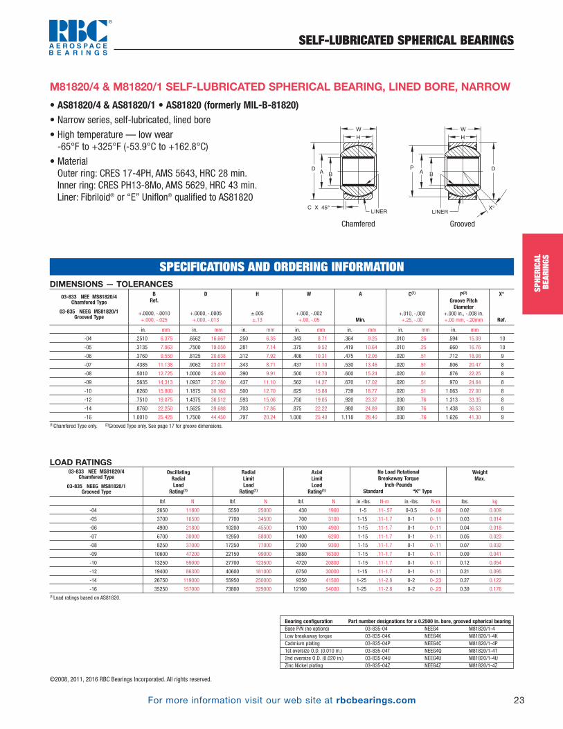
For more information visit our web site at rbcbearings.com
SELF-LUBRICATED SPHERICAL BEARINGS
23
SPHE
RICA
LBE
ARIN
GS
©2008, 2011, 2016 RBC Bearings Incorporated. All rights reserved.
• AS81820/4 & AS81820/1 • AS81820 (formerly MIL-B-81820)• Narrow series, self-lubricated, lined bore
• High temperature — low wear-65°F to +325°F (-53.9°C to +162.8°C)
• MaterialOuter ring: CRES 17-4PH, AMS 5643, HRC 28 min.Inner ring: CRES PH13-8Mo, AMS 5629, HRC 43 min.Liner: Fibriloid® or “E” Uniflon® qualified to AS81820
M81820/4 & M81820/1 SELF-LUBRICATED SPHERICAL BEARING, LINED BORE, NARROW
DIMENSIONS — TOLERANCES
in. mm in. mm in. mm in. mm in. mm in. mm in. mm
-04 .2510 6.375 .6562 16.667 .250 6.35 .343 8.71 .364 9.25 .010 .25 .594 15.09 10
-05 .3135 7.963 .7500 19.050 .281 7.14 .375 9.52 .419 10.64 .010 .25 .660 16.76 10
-06 .3760 9.550 .8125 20.638 .312 7.92 .406 10.31 .475 12.06 .020 .51 .712 18.08 9
-07 .4385 11.138 .9062 23.017 .343 8.71 .437 11.10 .530 13.46 .020 .51 .806 20.47 8
-08 .5010 12.725 1.0000 25.400 .390 9.91 .500 12.70 .600 15.24 .020 .51 .876 22.25 8
-09 .5635 14.313 1.0937 27.780 .437 11.10 .562 14.27 .670 17.02 .020 .51 .970 24.64 8
-10 .6260 15.900 1.1875 30.162 .500 12.70 .625 15.88 .739 18.77 .020 .51 1.063 27.00 8
-12 .7510 19.075 1.4375 36.512 .593 15.06 .750 19.05 .920 23.37 .030 .76 1.313 33.35 8
-14 .8760 22.250 1.5625 39.688 .703 17.86 .875 22.22 .980 24.89 .030 .76 1.438 36.53 8
-16 1.0010 25.425 1.7500 44.450 .797 20.24 1.000 25.40 1.118 28.40 .030 .76 1.626 41.30 9(1)Chamfered Type only. (2)Grooved Type only. See page 17 for groove dimensions.
X°
Ref.
P(2)
Groove PitchDiameter
+.000 in., -.008 in. +.00 mm, -.20mm
C(1)
+.010, -.000 +.25, -.00
A
Min.
W
+.000, -.002 +.00, -.05
H
±.005 ±.13
D
+.0000, -.0005 +.000, -.013
BRef.
+.0000, -.0010 +.000, -.025
03-833 NEE MS81820/4 Chamfered Type
03-835 NEEG MS81820/1 Grooved Type
LOAD RATINGS
lbf. N lbf. N lbf. N in.-lbs. N-m in.-lbs. N-m lbs. kg
-04 2650 11800 5550 25000 430 1900 1-5 .11-.57 0-0.5 0-.06 0.02 0.009
-05 3700 16500 7700 34500 700 3100 1-15 .11-1.7 0-1 0-.11 0.03 0.014
-06 4900 21800 10200 45500 1100 4900 1-15 .11-1.7 0-1 0-.11 0.04 0.018
-07 6700 30000 12950 58000 1400 6200 1-15 .11-1.7 0-1 0-.11 0.05 0.023
-08 8250 37000 17250 77000 2100 9300 1-15 .11-1.7 0-1 0-.11 0.07 0.032
-09 10600 47200 22150 99000 3680 16300 1-15 .11-1.7 0-1 0-.11 0.09 0.041
-10 13250 59000 27700 123500 4720 20800 1-15 .11-1.7 0-1 0-.11 0.12 0.054
-12 19400 86300 40600 181000 6750 30000 1-15 .11-1.7 0-1 0-.11 0.21 0.095
-14 26750 119000 55950 250000 9350 41500 1-25 .11-2.8 0-2 0-.23 0.27 0.122
-16 35250 157000 73800 329000 12160 54000 1-25 .11-2.8 0-2 0-.23 0.39 0.176(1)Load ratings based on AS81820.
WeightMax.
No Load RotationalBreakaway Torque
Inch-PoundsStandard “K” Type
AxialLimitLoad
Rating(1)
RadialLimitLoad
Rating(1)
OscillatingRadialLoad
Rating(1)
03-833 NEE MS81820/4 Chamfered Type
03-835 NEEG MS81820/1 Grooved Type
Bearing configuration Part number designations for a 0.2500 in. bore, grooved spherical bearingBase P/N (no options) 03-835-04 NEEG4 M81820/1-4Low breakaway torque 03-835-04K NEEG4K M81820/1-4KCadmium plating 03-835-04P NEEG4C M81820/1-4P1st oversize O.D. (0.010 in.) 03-835-04T NEEG4Q M81820/1-4T2nd oversize O.D. (0.020 in.) 03-835-04U NEEG4U M81820/1-4UZinc Nickel plating 03-835-04Z NEEG4Z M81820/1-4Z
SPECIFICATIONS AND ORDERING INFORMATION
Chamfered Grooved
AB
LINER
G
W
H
C X 45° X°
PDA
B
LINER
W
H
D
PB_018_048_8-30-16_Pln_018_050.qxd 8/30/16 11:00 AM Page 23
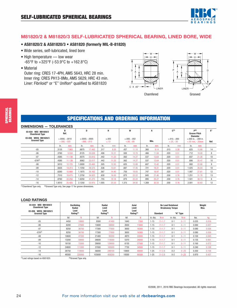
For more information visit our web site at rbcbearings.com
SELF-LUBRICATED SPHERICAL BEARINGS
24
SPHE
RICA
LBE
ARIN
GS
©2008, 2011, 2016 RBC Bearings Incorporated. All rights reserved.
SPHE
RICA
LBE
ARIN
GS
M81820/2 & M81820/3 SELF-LUBRICATED SPHERICAL BEARING, LINED BORE, WIDE
DIMENSIONS — TOLERANCES
in. mm in. mm in. mm in. mm in. mm in. mm in. mm
-05 .3135 7.963 .6875 17.462 .317 8.05 .437 11.10 .360 9.14 .015 0.38 .625 15.88 14
-06 .3760 9.550 .8125 20.638 .406 10.31 .500 12.70 .466 11.84 .020 0.51 .712 18.08 8
-07 .4385 11.138 .9375 23.813 .442 11.23 .562 14.27 .537 13.64 .020 0.51 .837 21.26 10
-07A(2) .4385 11.138 .9062 23.017 .442 11.23 .562 14.27 .537 13.64 .020 0.51 .806 20.47 10
-08 .5010 12.725 1.0000 25.400 .505 12.83 .625 15.88 .607 15.42 .020 0.51 .900 22.86 9
-09 .5635 14.313 1.1250 28.575 .536 13.61 .687 17.45 .721 18.31 .020 0.51 1.025 26.04 10
-10 .6260 15.900 1.1875 30.162 .567 14.40 .750 19.05 .747 18.97 .020 0.51 1.087 27.61 12
-12 .7510 19.075 1.3750 34.925 .630 16.00 .875 22.22 .845 21.46 .030 0.76 1.251 31.78 13
-14 .8760 22.250 1.6250 41.275 .755 19.18 .875 22.22 .995 25.27 .030 0.76 1.501 38.13 6
-16 1.0010 25.425 2.1250 53.975 1.005 25.53 1.375 34.92 1.269 32.33 .030 0.76 2.001 50.83 12(1)Chamfered Type only. (2)Grooved Type only. See page 17 for groove dimensions.
X°
Ref.
P(2)
Groove PitchDiameter
+.000 in., -.008 in.+.00 mm, -.20mm
C(1)
+.010, -.000 +.25, -.00
A
Min.
W
+.000, -.002 +.00, -.05
H
±.005 ±.13
D
+.0000, -.0005 -.000, -.013
BRef.
+.0000, -.0010 +.000, -.025
03-834 WEE M81820/2Chamfered Type
03-836 WEEG M81820/3Grooved Type
LOAD RATINGS
lbf. N lbf. N lbf. N in.-lbs. N-m in.-lbs. N-m lbs. kg
-05 4450 19800 9300 41400 1640 7350 1-15 .11-1.7 0-1 0-.11 0.035 0.016
-06 6200 27600 13000 58000 2630 11600 1-15 .11-1.7 0-1 0-.11 0.060 0.027
-07 8250 36700 17300 77000 3650 16300 1-15 .11-1.7 0-1 0-.11 0.080 0.036
-07A(2) 8250 36700 17300 77000 3650 16300 1-15 .11-1.7 0-1 0-.11 0.080 0.036
-08 10600 47200 21400 95200 4970 22000 1-15 .11-1.7 0-1 0-.11 0.100 0.045
-09 13200 59000 26600 118300 5370 24000 1-15 .11-1.7 0-1 0-.11 0.135 0.061
-10 16150 72000 29000 129000 6130 27500 1-15 .11-1.7 0-1 0-.11 0.160 0.072
-12 24800 111000 37000 165000 7730 34500 1-15 .11-1.7 0-1 0-.11 0.240 0.108
-14 26750 119000 56000 249100 10800 48000 1-25 .11-2.8 0-2 0-.23 0.350 0.158
-16 49300 220000 103000 458200 19300 86500 1-25 .11-2.8 0-2 0-.23 0.970 0.437(1)Load ratings based on AS81820. (2)Grooved Type only.
WeightMax.
No Load RotationalBreakaway Torque
Standard “K” Type
AxialLimitLoad
Rating(1)
RadialLimitLoad
Rating(1)
OscillatingRadialLoad
Rating(1)
03-834 WEE M81820/2Chamfered Type
03-836 WEEG M81820/3Grooved Type
SPECIFICATIONS AND ORDERING INFORMATION
• AS81820/2 & AS81820/3 • AS81820 (formerly MIL-B-81820)• Wide series, self-lubricated, lined bore
• High temperature — low wear-65°F to +325°F (-53.9°C to +162.8°C)
• MaterialOuter ring: CRES 17-4PH, AMS 5643, HRC 28 min.Inner ring: CRES PH13-8Mo, AMS 5629, HRC 43 min.Liner: Fibriloid® or “E” Uniflon® qualified to AS81820
Chamfered Grooved
AB
LINER
W
H
C X 45° X°
PDA
B
LINER
W
H
D
PB_018_048_8-30-16_Pln_018_050.qxd 8/30/16 11:00 AM Page 24
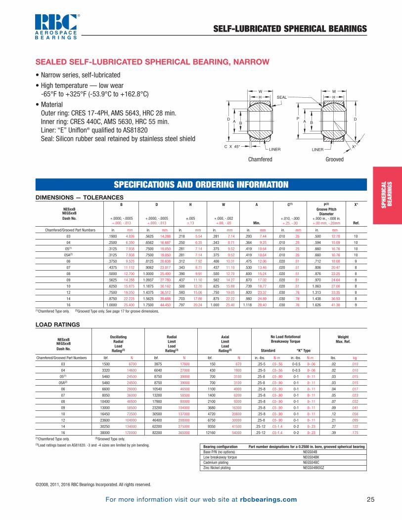
For more information visit our web site at rbcbearings.com
SELF-LUBRICATED SPHERICAL BEARINGS
25
SPHE
RICA
LBE
ARIN
GS
©2008, 2011, 2016 RBC Bearings Incorporated. All rights reserved.
• Narrow series, self-lubricated
• High temperature — low wear-65°F to +325°F (-53.9°C to +162.8°C)
• MaterialOuter ring: CRES 17-4PH, AMS 5643, HRC 28 min.Inner ring: CRES 440C, AMS 5630, HRC 55 min.Liner: “E” Uniflon® qualified to AS81820Seal: Silicon rubber seal retained by stainless steel shield
A B
LINER
W
H
C X 45° X°
PDA
B
LINER
W
H
D
SEAL
SEALED SELF-LUBRICATED SPHERICAL BEARING, NARROW
DIMENSIONS — TOLERANCES
Chamfered/Grooved Part Numbers in. mm in. mm in. mm in. mm in. mm in. mm in. mm
03 .1900 4.826 .5625 14.288 .218 5.54 .281 7.14 .293 7.44 .010 .25 .500 12.70 10
04 .2500 6.350 .6562 16.667 .250 6.35 .343 8.71 .364 9.25 .010 .25 .594 15.09 10
05(1) .3125 7.938 .7500 19.050 .281 7.14 .375 9.52 .419 10.64 .010 .25 .660 16.76 10
05A(2) .3125 7.938 .7500 19.050 .281 7.14 .375 9.52 .419 10.64 .010 .25 .660 16.76 10
06 .3750 9.525 .8125 20.638 .312 7.92 .406 10.31 .475 12.06 .020 .51 .712 18.08 9
07 .4375 11.112 .9062 23.017 .343 8.71 .437 11.10 .530 13.46 .020 .51 .806 20.47 8
08 .5000 12.700 1.0000 25.400 .390 9.91 .500 12.70 .600 15.24 .020 .51 .876 22.25 8
09 .5625 14.288 1.0937 27.780 .437 11.10 .562 14.27 .670 17.02 .020 .51 .970 24.64 8
10 .6250 15.875 1.1875 30.162 .500 12.70 .625 15.88 .739 18.77 .020 .51 1.063 27.00 8
12 .7500 19.050 1.4375 36.512 .593 15.06 .750 19.05 .920 23.37 .030 .76 1.313 33.35 8
14 .8750 22.225 1.5625 39.688 .703 17.86 .875 22.22 .980 24.89 .030 .76 1.438 36.53 8
16 1.0000 25.400 1.7500 44.450 .797 20.24 1.000 25.40 1.118 28.40 .030 .76 1.626 41.30 9(1)Chamfered Type only. (2)Grooved Type only. See page 17 for groove dimensions.
X°
Ref.
P(2)
Groove PitchDiameter
+.000 in., -.008 in.+.00 mm, -.20mm
C(1)
+.010, -.000 +.25, -.00
A
Min.
W
+.000, -.002 +.00, -.05
H
±.005 ±.13
D
+.0000, -.0005 +.000, -.013
B
+.0000, -.0005 +.000, -.013
NESxxBNEGSxxBDash No.
LOAD RATINGS
Chamfered/Grooved Part Numbers lbf. N lbf. N lbf. N in.-lbs. N-m in.-lbs. N-m lbs. kg
03 1500 6700 3975 17600 150 670 .25-5 .03-.56 0-0.5 0-.06 .02 .010
04 3320 14600 6040 27000 430 1900 .25-5 .03-.56 0-0.5 0-.06 .02 .010
05(1) 5460 24500 8750 39000 700 3100 .25-8 .03-.90 0-1 0-.11 .03 .015
05A(2) 5460 24500 8750 39000 700 3100 .25-8 .03-.90 0-1 0-.11 .03 .015
06 6600 29000 10540 46500 1100 4900 .25-8 .03-.90 0-1 0-.11 .04 .017
07 8050 36000 13200 58500 1400 6200 .25-8 .03-.90 0-1 0-.11 .05 .023
08 10400 46500 17900 80000 2100 9300 .25-8 .03-.90 0-1 0-.11 .07 .032
09 13000 58500 23200 104000 3680 16300 .25-8 .03-.90 0-1 0-.11 .09 .041
10 16450 73500 30500 137000 4720 20800 .25-8 .03-.90 0-1 0-.11 .12 .056
12 23600 104000 46400 208000 6750 30000 .25-8 .03-.90 0-1 0-.11 .21 .095
14 30250 134000 62200 275000 9350 41500 .25-12 .03-1.4 0-2 0-.23 .27 .122
16 38000 170000 82200 365000 12160 54000 .25-12 .03-1.4 0-2 0-.23 .39 .175(1)Chamfered Type only. (2)Grooved Type only.(3)Load ratings based on AS81820. -3 and -4 sizes are limited by pin bending.
WeightMax. Ref.
No Load RotationalBreakaway Torque
Standard “K” Type
AxialLimitLoad
Rating(3)
RadialLimitLoad
Rating(3)
OscillatingRadialLoad
Rating(3)
NESxxBNEGSxxBDash No.
Chamfered Grooved
Bearing configuration Part number designations for a 0.2500 in. bore, grooved spherical bearingBase P/N (no options) NEGS04BLow breakaway torque NEGS04BKCadmium plating NEGS04BCZinc Nickel plating NEGS04BIOGZ
SPECIFICATIONS AND ORDERING INFORMATION
SPHE
RICA
LBE
ARIN
GSPB_018_048_8-30-16_Pln_018_050.qxd 8/30/16 11:00 AM Page 25

For more information visit our web site at rbcbearings.com
SEALED SELF-LUBRICATED SPHERICAL BEARINGS
26
SPHE
RICA
LBE
ARIN
GS
©2008, 2011, 2016 RBC Bearings Incorporated. All rights reserved.
SPHE
RICA
LBE
ARIN
GS
• Wide series, self-lubricated
• High temperature — low wear-65°F to +325°F (-53.9°C to +162.8°C)
• MaterialOuter ring: CRES 17-4PH, AMS 5643, HRC 28 min.Inner ring: CRES 440C, AMS 5630, HRC 55 min.Liner: “E” Uniflon® qualified to AS81820Seal: Silicon rubber seal retained by stainless steel shield
SEALED SELF-LUBRICATED SPHERICAL BEARING, WIDE
DIMENSIONS — TOLERANCES
Chamfered/Grooved Part Numbers in. mm in. mm in. mm in. mm in. mm in. mm in. mm
03 .1900 4.826 .6250 15.875 .327 8.31 .437 11.10 .300 7.62 .010 0.25 .563 14.30 15
04 .2500 6.350 .6250 15.875 .327 8.31 .437 11.10 .300 7.62 .010 0.25 .563 14.30 15
05 .3125 7.938 .6875 17.462 .317 8.05 .437 11.10 .360 9.14 .010 0.25 .625 15.88 14
06 .3750 9.525 .8125 20.638 .406 10.31 .500 12.70 .466 11.84 .020 0.51 .712 18.08 8
07A(2) .4375 11.112 .9062 23.017 .442 11.23 .562 14.27 .537 13.64 .020 0.51 .806 20.47 10
07 .4375 11.112 .9375 23.812 .442 11.23 .562 14.27 .537 13.64 .020 0.51 .837 21.26 10
08 .5000 12.700 1.0000 25.400 .505 12.83 .625 15.88 .607 15.42 .020 0.51 .900 22.86 9
09 .5625 14.288 1.1250 28.575 .536 13.61 .687 17.45 .721 18.31 .020 0.51 1.025 26.04 10
10 .6250 15.875 1.1875 30.162 .567 14.40 .750 19.05 .747 18.97 .020 0.51 1.087 27.61 12
12 .7500 19.050 1.3750 34.925 .630 16.00 .875 22.22 .845 21.46 .030 0.76 1.251 31.78 13
14 .8750 22.225 1.6250 41.275 .755 19.18 .875 22.22 .995 25.27 .030 0.76 1.501 38.13 6
16 1.0000 25.400 2.1250 53.975 1.005 25.53 1.375 34.92 1.269 32.23 .030 0.76 2.001 50.83 12(1)Chamfered Type only. (2)Grooved Type only. See page 17 for groove dimensions.
X°
Ref.
P(2)
Groove PitchDiameter
+.000 in., -.008 in.+.00 mm, -.20mm
C(1)
+.010, -.000 +.25, -.00
A
Min.
W
+.000, -.002 +.00, -.05
H
±.005 ±.13
D
+.0000, -.0005 +.000, -.013
B
+.0000, -.0005 +.000, -.013
WESxxWWEGSxxWDash No.
LOAD RATINGS
Chamfered/Grooved Part Numbers lbf. N lbf. N lbf. N in.-lbs. N-m in.-lbs. N-m lbs. kg
03 4900 21600 2500 11100 1770 7800 .25-5 .03-.56 0.05 0-.06 .031 .014
04 4900 21600 5500 24400 1770 7800 .25-5 .03-.56 0.05 0-.06 .031 .014
05 6050 27000 9400 41800 1640 7350 .25-8 .03-.90 0.10 0-.11 .035 .016
06 8310 36500 13700 60900 2630 11600 .25-8 .03-.90 0.10 0-.11 .060 .027
07A(2) 11750 52000 19700 87600 3650 16300 .25-8 .03-.90 0.10 0-.11 .080 .036
07 11750 52000 20700 92000 3650 16300 .25-8 .03-.90 0.10 0-.11 .080 .036
08 14950 65500 21400 95000 4970 22000 .25-8 .03-.90 0.10 0-.11 .100 .045
09 18100 80000 26600 118000 5370 24000 .25-8 .03-.90 0.10 0-.11 .135 .061
10 20250 90000 29000 128500 6130 27500 .25-8 .03-.90 0.10 0-.11 .160 .072
12 26200 116000 37000 164500 7730 34500 .25-8 .03-.90 0.10 0-.11 .240 .110
14 33600 150000 65200 290000 10800 48000 .25-12 .03-1.4 0.20 0-.23 .350 .160
16 56250 250000 104000 462500 19300 86500 .25-12 .03-1.4 0.20 0-.23 .970 .440(1)Chamfered Type only. (2)Grooved Type only.(3)Load ratings based on AS81820. -3 and -4 sizes are limited by pin bending.
WeightMax. Ref.
No Load RotationalBreakaway Torque
Standard “K” Type
AxialLimitLoad
Rating(3)
RadialLimitLoad
Rating(3)
OscillatingRadialLoad
Rating(3)
WESxxWWEGSxxWDash No.
Bearing configuration Part number designations for a 0.2500 in. bore, grooved spherical bearingBase P/N (no options) WEGS04WLow breakaway torque WEGS04WKCadmium plating WEGS04WCZinc Nickel plating WEGS04WZ
SPECIFICATIONS AND ORDERING INFORMATION
Chamfered Grooved
A B
LINER
G
W
H
C X 45° X°
PDA
B
LINER
W
H
D
SEAL
PB_018_048_8-30-16_Pln_018_050.qxd 8/30/16 11:00 AM Page 26
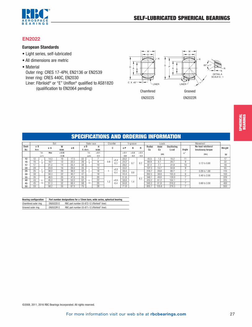
For more information visit our web site at rbcbearings.com
SELF-LUBRICATED SPHERICAL BEARINGS
27
SPHE
RICA
LBE
ARIN
GS
©2008, 2011, 2016 RBC Bearings Incorporated. All rights reserved.
European Standards • Light series, self-lubricated
• All dimensions are metric
• MaterialOuter ring: CRES 17-4PH, EN2136 or EN2539Inner ring: CRES 440C, EN2030Liner: Fibriloid® or “E” Uniflon® qualified to AS81820
(qualification to EN2064 pending)
D
AB
A
K
60° ± 1°
LINER
G
W
H
C X 45°
RPD
AB
K
LINER
W
H
DETAIL A
SCALE 6 : 1
N
EN2022
SPECIFICATIONS AND ORDERING INFORMATION
Bearing configuration Part number designations for a 12mm bore, wide series, spherical bearing
Chamfered outer ring EN2022S12 RBC part number 03-872-12 (Fibriloid® liner)
Grooved outer ring EN2022R12 RBC part number 03-871-12 (Fibriloid® liner)
Chamfered
EN2022S
Grooved
EN2022R
SPHE
RICA
LBE
ARIN
GSPB_018_048_8-30-16_Pln_018_050.qxd 8/30/16 11:00 AM Page 27
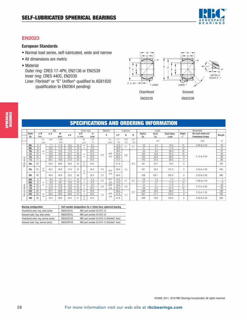
For more information visit our web site at rbcbearings.com
SELF-LUBRICATED SPHERICAL BEARINGS
28
SPHE
RICA
LBE
ARIN
GS
©2008, 2011, 2016 RBC Bearings Incorporated. All rights reserved.
SPHE
RICA
LBE
ARIN
GS
European Standards • Normal load series, self-lubricated, wide and narrow
• All dimensions are metric
• MaterialOuter ring: CRES 17-4PH, EN2136 or EN2539Inner ring: CRES 440C, EN2030Liner: Fibriloid® or “E” Uniflon® qualified to AS81820
(qualification to EN2064 pending)
EN2023
Bearing configuration Part number designations for a 12mm bore, spherical bearing
Chamfered outer ring, wide series EN2023S12L RBC part number 03-875-12
Grooved outer ring, wide series EN2023R12L RBC part number 03-873-12
Chamfered outer ring, narrow series EN2023S12E RBC part number 03-876-12 (Fibriloid® liner)
Grooved outer ring, narrow series EN2023R12E RBC part number 03-874-12 (Fibriloid® liner)
SPECIFICATIONS AND ORDERING INFORMATION
D
AB
A
K
60° ± 1°
LINER
G
W
H
C X 45°
RPD
AB
K
LINER
W
H
DETAIL A
SCALE 6 : 1
N
Chamfered
EN2023S
Grooved
EN2023R
PB_018_048_8-30-16_Pln_018_050.qxd 8/30/16 11:00 AM Page 28
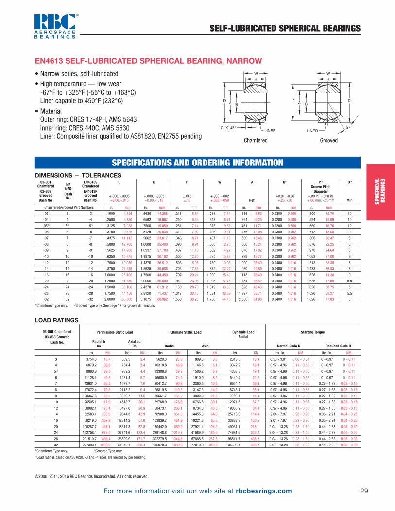
For more information visit our web site at rbcbearings.com
SELF-LUBRICATED SPHERICAL BEARINGS
29
SPHE
RICA
LBE
ARIN
GS
©2008, 2011, 2016 RBC Bearings Incorporated. All rights reserved.
• Narrow series, self-lubricated
• High temperature — low wear-67°F to +325°F (-55°C to +163°C) Liner capable to 450°F (232°C)
• MaterialOuter ring: CRES 17-4PH, AMS 5643Inner ring: CRES 440C, AMS 5630Liner: Composite liner qualified to AS81820, EN2755 pending
EN4613 SELF-LUBRICATED SPHERICAL BEARING, NARROW
LOAD RATINGS
lbs. KN lbs. KN lbs. KN lbs. KN lbs. KN lbs.-in. NM lbs.-in. NM
3 3754.3 16.7 539.5 2.4 5620.3 25.0 809.3 3.6 2315.5 10.3 0.53 - 3.01 0.06 - 0.34 0 - 0.97 0 - 0.11
4 6879.2 30.6 764.4 3.4 10318.8 45.9 1146.5 5.1 3372.2 15.0 0.97 - 4.96 0.11 - 0.56 0 - 0.97 0 - 0.11
5(1) 8880.0 39.5 989.2 4.4 13308.8 59.2 1506.2 6.7 4338.8 19.3 0.97 - 4.96 0.11 - 0.56 0 - 0.97 0 - 0.11
6 11128.1 49.5 1281.4 5.7 16680.9 74.2 1910.9 8.5 5440.4 24.2 0.97 - 4.96 0.11 - 0.56 0 - 0.97 0 - 0.11
7 13601.0 60.5 1573.7 7.0 20412.7 90.8 2360.5 10.5 6654.4 29.6 0.97 - 4.96 0.11 - 0.56 0.27 - 1.33 0.03 - 0.15
8 17872.4 79.5 2113.2 9.4 26819.8 119.3 3147.3 14.0 8745.1 38.9 0.97 - 4.96 0.11 - 0.56 0.27 - 1.33 0.03 - 0.15
9 20367.8 90.6 3259.7 14.5 30551.7 135.9 4900.9 21.8 9959. I 44.3 0.97 - 4.96 0.11 - 0.56 0.27 - 1.33 0.03 - 0.15
10 26505.1 117.9 4518.7 20.1 39768.9 176.9 6766.8 30.1 12971.5 57.7 0.97 - 4.96 0.11 - 0.56 0.27 - 1.33 0.03 - 0.15
12 38982.1 173.4 6497.0 28.9 58473.1 260.1 9734.3 43.3 19063.9 84.8 0.97 - 4.96 0.11 - 0.56 0.27 - 1.33 0.03 - 0.15
14 52583.1 233.9 9644.3 42.9 78908.3 351.0 14455.3 64.3 25718.3 114.4 2.04 - 7.97 0.23 - 0.90 0.35 - 2.21 0.04 - 0.25
16 69219.0 307.9 12814.2 57.0 103839.7 461.9 19221.3 85.5 33833.9 150.5 2.04 - 7.97 0.23 - 0.90 0.35 - 2.21 0.04 - 0.25
20 100287.7 446.1 18614.3 82.8 150442.9 669.2 27921.4 124.2 49031.1 218.1 2.04 - 13.28 0.23 - 1.50 0.44 - 2.83 0.05 - 0.32
24 152758.4 679.5 27741.6 123.4 229148.8 1019.3 41589.9 185.0 74681.9 332.2 2.04 - 13.28 0.23 - 1.50 0.44 - 2.83 0.05 - 0.32
28 201519.7 896.4 38599.9 171.7 302279.5 1344.6 57888.6 257.5 98511.7 438.2 2.04 - 13.28 0.23 - 1.50 0.44 - 2.83 0.05 - 0.32
32 277393.1 1233.9 51346.1 228.4 416078.3 1850.8 77019.9 342.6 135605.4 603.2 2.04 - 13.28 0.23 - 1.50 0.44 - 2.83 0.05 - 0.32(1)Chamfered Type only. (2)Grooved Type only.(3)Load ratings based on AS81820. -3 and -4 sizes are limited by pin bending.
Starting Torque
Normal Code N Reduced Code R
Dynamic LoadRadial
Ultimate Static Load
Radial Axial
Permissible Static Load
Radial b Axial acCs Ca
03-861 Chamfered03-863 Grooved
Dash No.
SPECIFICATIONS AND ORDERING INFORMATIONDIMENSIONS — TOLERANCES
Chamfered/Grooved Part Numbers in. mm in. mm in. mm in. mm in. mm in. mm in. mm
-03 3 -3 .1900 4.826 .5625 14.288 .218 5.54 .281 7.14 .336 8.53 0.0200 0.508 .500 12.70 10
-04 4 -4 .2500 6.350 .6562 16.667 .250 6.35 .343 8.71 .364 9.25 0.0200 0.508 .594 15.09 10
-05(1) 5(1) -5(1) .3125 7.938 .7500 19.050 .281 7.14 .375 9.52 .461 11.71 0.0200 0.508 .660 16.76 10
-06 6 -6 .3750 9.525 .8125 20.638 .312 7.92 .406 10.31 .475 12.06 0.0300 0.762 .712 18.08 9
-07 7 -7 .4375 11.112 .9062 23.017 .343 8.71 .437 11.10 .530 13.46 0.0300 0.762 .806 20.47 8
-08 8 -8 .5000 12.700 1.0000 25.400 .390 9.91 .500 12.70 .600 15.24 0.0300 0.762 .876 22.25 8
-09 9 -9 .5625 14.288 1.0937 27.780 .437 11.10 .562 14.27 .670 17.02 0.0300 0.762 .970 24.64 8
-10 10 -10 .6250 15.875 1.1875 30.162 .500 12.70 .625 15.88 .739 18.77 0.0300 0.762 1.063 27.00 8
-12 12 -12 .7500 19.050 1.4375 36.512 .593 15.06 .750 19.05 1.000 25.40 0.0400 1.016 1.313 33.35 8
-14 14 -14 .8750 22.225 1.5625 39.688 .703 17.86 .875 22.22 .980 24.89 0.0400 1.016 1.438 36.53 8
-16 16 -16 1.0000 25.400 1.7500 44.450 .797 20.24 1.000 25.40 1.118 28.40 0.0400 1.016 1.626 41.30 9
-20 20 -20 1.2500 31.750 2.0000 50.800 .942 23.93 1.093 27.76 1.434 36.42 0.0400 1.016 1.626 47.65 5.5
-24 24 -24 1.5000 38.100 2.4370 61.912 1.130 28.70 1.312 33.33 1.828 46.43 0.0400 1.016 1.626 58.75 5
-28 28 -28 1.7500 44.450 2.8120 71.437 1.317 33.45 1.531 38.89 1.997 50.71 0.0400 1.016 1.626 68.27 5.5
-32 32 -32 2.0000 50.800 3.1875 80.962 1.560 38.23 1.750 44.45 2.530 61.98 0.0400 1.016 1.626 77.83 5(1)Chamfered Type only. (2)Grooved Type only. See page 17 for groove dimensions.
X°
Min.
P(2)
Groove PitchDiameter
+.00 in., -.010 in.+.00 mm, -.25mm
C(1)
+0.01, -0.00 +.25, -.00
A
Ref.
W
+.000, -.002 +.000, -.050
H
±.005 ±.13
D
+.000, -.0005 +0.00, -.013
B
+.000, -.0005 +0.00, -.013
03-861Chamfered03-863GroovedDash No.
NENEGDash No.
EN4613SChamferedEN4613RGroovedDash No.
A B
LINER
G
W
H
C X 45° X°
PDA
B
LINER
W
H
D
Chamfered Grooved
SPHE
RICA
LBE
ARIN
GSPB_018_048_8-30-16_Pln_018_050.qxd 8/30/16 11:00 AM Page 29

For more information visit our web site at rbcbearings.com
SELF-LUBRICATED SPHERICAL BEARINGS
30
SPHE
RICA
LBE
ARIN
GS
©2008, 2011, 2016 RBC Bearings Incorporated. All rights reserved.
SPHE
RICA
LBE
ARIN
GS
EN4614 SELF-LUBRICATED SPHERICAL BEARING, WIDE
LOAD RATINGS
lbs. KN lbs. KN lbs. KN lbs. KN lbs. KN lbs.-in. NM lbs.-in. NM
3 2405 10.7 1416 6.3 3619 16.1 2113 9.4 2405 10.7 0.50 - 5.0 0.06 - 0.56 0 - 0.97 0 - 0.11
4 5508 24.5 1416 6.3 8250 36.7 2113 9.4 4878 21.7 0.97 - 4.96 0.11 - 0.56 0 - 0.97 0 - 0.11
5 10251 45.6 1326 5.9 15377 68.4 1978 8.8 5013 22.3 0.97 - 4.96 0.11 - 0.56 0 - 0.97 0 - 0.11
6 16209 72.1 2293 10.2 24324 108.2 3440 15.3 8003 35.6 0.97 - 4.96 0.11 - 0.56 0 - 0.97 0 - 0.11
7 & 7A 20435 90.9 2765 12.3 30664 136.4 4159 18.5 9982 44.4 0.97 - 4.96 0.11 - 0.56 0.27 - 1.33 0.03 - 0.15
8 26482 117.8 3705 16.5 39746 176.8 5553 24.7 12949 57.6 0.97 - 4.96 0.11 - 0.56 0.27 - 1.33 0.03 - 0.15
9 29607 131.7 5328 23.7 44400 197.5 7981 35.5 14478 64.4 0.97 - 4.96 0.11 - 0.56 0.27 - 1.33 0.03 - 0.15
10 33609 149.5 6070 27.0 50425 224.3 9105 40.5 16435 73.1 0.97 - 4.96 0.11 - 0.56 0.27 - 1.33 0.03 - 0.15
12 42894 190.8 7486 33.3 64318 286.1 11218 49.9 20975 93.3 0.97 - 4.96 0.11 - 0.56 0.27 - 1.33 0.03 - 0.15
14 57551 256.0 11352 50.5 86304 383.9 17018 75.7 28124 125.1 2.04 - 7.97 0.23 - 0.90 0.35 - 2.21 0.04 - 0.25
16 111797 497.3 21469 95.5 167685 745.9 32215 143.3 54651 243.1 2.04 - 7.97 0.23 - 0.90 0.35 - 2.21 0.04 - 0.25
20 142237 632.7 27741 123.4 213344 949.0 41590 185.0 69533 309.3 2.04 - 13.28 0.23 - 1.50 0.44 - 2.83 0.05 - 0.32
24 181983 809.5 32912 146.4 272963 1214.2 49368 219.6 88957 395.7 2.04 - 13.28 0.23 - 1.50 0.44 - 2.83 0.05 - 0.32
28 214041 952.1 38600 171.7 321072 1428.2 57888 257.5 104649 465.5 2.04 - 13.28 0.23 - 1.50 0.44 - 2.83 0.05 - 0.32
32 247357 1100.3 42669 189.8 371025 1650.4 64003 284.7 120925 537.9 2.04 - 13.28 0.23 - 1.50 0.44 - 2.83 0.05 - 0.32(1)Chamfered Type only. (2)Grooved Type only.(3)Load ratings based on AS81820. -3 and -4 sizes are limited by pin bending.
Starting Torque
Normal Code N Reduced Code R
Dynamic LoadRadial
Ultimate Static Load
Radial Axial
Permissible Static Load
Radial b Axial acCs Ca
03-862 Chamfered03-864 Grooved
Dash No.
SPECIFICATIONS AND ORDERING INFORMATIONDIMENSIONS — TOLERANCES
Chamfered/Grooved Part Numbers in. mm in. mm in. mm in. mm in. mm in. mm in. mm
-03 3 -3 .1900 4.826 .6250 15.875 .327 8.31 .437 11.10 .300 7.62 0.0200 0.508 .563 14.30 15
-04 4 -4 .2500 6.350 .6250 15.875 .327 8.31 .437 11.10 .300 7.62 0.0200 0.508 .563 14.30 15
-05 5 -5 .3125 7.938 .6875 17.452 .317 8.05 .437 11.10 .360 9.14 0.0200 0.508 .625 15.87 14
-06 6 -6 .3750 9.525 .8125 20.638 .405 10.31 .500 12.70 .466 11.84 0.0300 0.762 .712 18.08 8
-07 7 -7 .4375 11.112 .9375 23.812 .442 11.23 .582 14.28 .537 13.64 0.0300 0.762 .837 21.26 10
-07A 7A -7A .4375 11.112 .9062 23.017 .442 11.23 .582 14.28 .537 13.64 - - .808 20.52 10
-08 8 -8 .5000 12.700 1.0000 25.400 .505 12.83 .625 15.88 .607 15.42 0.0300 0.762 .900 22.86 9
-09 9 -9 .5625 14.288 1.1250 28.575 .536 13.61 .687 17.45 .721 18.31 0.0300 0.762 1.025 26.03 10
-10 10 -10 .6250 15.875 1.1875 30.162 .567 14.40 .750 19.05 .747 18.97 0.0300 0.762 1.087 27.60 12
-12 12 -12 .7500 19.050 1.3750 34.925 .630 16.00 .875 22.22 .845 21.46 0.0400 1.016 1.251 31.78 13
-14 14 -14 .8750 22.225 1.6250 41.275 .755 19.18 .875 22.22 .995 25.27 0.0400 1.016 1.501 38.12 6
-16 16 -16 1.0000 25.400 2.1250 53.975 1.005 25.53 1.375 34.93 1.269 32.23 0.0400 1.016 2.001 50.82 12
-20 20 -20 1.2500 31.750 2.3750 60.325 1.130 28.70 1.500 38.10 1.483 37.15 0.0400 1.016 2.251 57.17 12
-24 24 -24 1.5000 38.100 2.6875 68.262 1.223 31.08 1.687 42.85 1.791 45.50 0.0400 1.016 2.562 65.08 13
-28 28 -28 1.7500 44.450 3.0000 76.200 1.317 33.45 1.812 46.02 1.965 49.90 0.0400 1.016 2.876 73.05 12
-32 32 -32 2.0000 50.800 3.2500 82.550 1.380 35.05 1.937 49.19 2.209 56.10 0.0400 1.016 3.124 79.35 12(1)Chamfered Type only. (2)Grooved Type only. See page 17 for groove dimensions.
X°
Min.
P(2)
Groove PitchDiameter
+.00 in., -.010 in.+.00 mm, -.25mm
C(1)
+0.01, -0.00 +.25, -.00
A
Ref.
W
+.000, -.002 +.000, -.050
H
±.005 ±.13
D
+.000, -.0005 +0.00, -.013
B
+.000, -.0005 +0.00, -.013
03-862Chamfered03-864GroovedDash No.
NENEGDash No.
EN4614SChamferedEN4614RGroovedDash No.
• Wide series, self-lubricated
• High temperature — low wear-67°F to +325°F (-55°C to +163°C) Liner capable to 450°F (232°C)
• MaterialOuter ring: CRES 17-4PH, AMS 5643Inner ring: CRES 440C, AMS 5630Liner: Composite liner qualified to AS81820, EN2755 pending
A B
LINER
W
H
C X 45° X°
PDA
B
LINER
W
H
D
Chamfered Grooved
PB_018_048_8-30-16_Pln_018_050.qxd 8/30/16 11:00 AM Page 30

For more information visit our web site at rbcbearings.com
METAL-TO-METAL SPHERICAL BEARINGS
31
SPHE
RICA
LBE
ARIN
GS
©2008, 2011, 2016 RBC Bearings Incorporated. All rights reserved.
AS81936/1 • AS81936 (FORMERLY MIL-B-81936)• Grooved, lubricated through ball and race
• MaterialInner ring: Beryllium copper per ASTM B194, B196
HRC 37 min.
Outer ring: CRES 17-4PH, AMS 5643, HRC 28 min.
• Prepacked with MIL-PRF-81322 grease
DIMENSIONS — TOLERANCES
inch inch inch inch inch inch inch inch inch inch inch inch lbs. lbs. lbs.
mm mm mm mm mm mm mm mm mm mm mm mm N N N
03-582-04 -4 0.25 0.6562 0.343 0.25 0.357 0.03 0.045 0.02 .596 .010/.015 .030/.057 .032/.062 12 6330 1930 0.03
6.35 16.667 8.71 6.35 9.07 0.76 1.14 0.51 15.138 0.25/0.38 0.76/1.45 0.81/1.57 28000 8500 0.014
03-582-05 -5 0.3125 0.75 0.375 0.281 0.413 0.04 0.055 0.03 652 .010/.015 .030/.062 .042/.062 11 8460 2450 0.04
7.938 19.05 9.52 7.14 10.49 1.02 1.4 0.76 16.561 0.25/0.38 0.76/1.57 1.07/1.57 37500 11000 0.018
03-582-06 -6 0.375 0.8125 0.406 0.312 0.509 0.04 0.055 0.03 .714 .010/.015 .030/.062 .042/.062 9 11400 3090 0.05
9.525 20.638 10.31 7.92 12.93 1.02 1.4 0.76 18.136 0.25/0.38 0.76/1.57 1.07/1.57 51000 13500 0.023
03-582-07 -7 0.4375 0.9062 0.437 0.343 0.563 0.04 0.055 0.03 .808 .010/.015 .060/.080 .052/.062 8 14800 3740 0.06
11.112 23.017 11.1 8.71 14.3 1.02 1.4 0.76 20.523 0.25/0.38 1.52/2.03 1.32/1.57 65500 16500 0.027
03-582-08 -8 0.5 1 0.5 0.39 0.634 0.06 0.08 0.03 .878 .010/.015 .060/.080 .052/.062 8 20400 4860 0.06
12.7 25.4 12.7 9.91 16.1 1.52 2.03 0.76 22.301 0.25/0.38 1.52/2.03 1.32/1.57 90000 21500 0.036
03-582-09 -9 0.5625 1.0937 0.562 0.437 0.664 0.06 0.08 0.03 .972 .010/.015 .060/.080 .052/.062 8 26700 6100 0.11
14.288 27.78 14.27 11.1 16.87 1.52 2.03 0.76 24.689 0.25/0.38 1.52/2.03 1.32/1.57 118000 27000 0.05
03-582-10 -10 0.625 1.1875 0.625 0.5 0.732 0.06 0.08 0.03 1.065 .010/.015 .070/.106 .062/.078 8 33100 8080 0.14
15.875 30.162 15.88 12.7 18.59 1.52 2.03 0.76 27.051 0.25/0.38 1.78/2.69 1.57/1.98 146000 36000 0.064
03-582-12 -12 0.75 1.4375 0.75 0.593 0.913 0.06 0.08 0.03 1.315 .010/.015 .070/.106 .062/.078 8 50000 11440 0.24
19.05 36.512 19.05 15.06 23.19 1.52 2.03 0.76 33.401 0.25/0.38 1.78/2.69 1.57/1.98 224000 51000 0.109
03-582-13 -13 0.8125 1.5625 0.812 0.65 0.984 0.06 0.08 0.03 1.440 .010/.015 .070/.106 .062/.078 8 59000 13800 0.31
20.638 39.688 20.62 16.51 24.99 1.52 2.03 0.76 36.576 0.25/0.38 1.78/2.69 1.57/1.98 260000 61000 0.141
03-582-14 -14 0.875 1.6562 0.875 0.703 1.054 0.06 0.08 0.03 1.534 .010/.015 .070/.106 .062/.078 8 70300 16160 0.37
22.225 42.067 22.22 17.86 26.77 1.52 2.03 0.76 38.964 0.25/0.38 1.78/2.69 1.57/1.98 315000 72000 0.168
03-582-16 -16 1 1.875 1 0.797 1.193 0.06 0.08 0.03 1.753 .010/.015 .090/.110 .078/.093 8 77700 20850 0.53
25.4 47.625 25.4 20.24 30.3 1.52 2.03 0.76 44.526 0.25/0.38 2.29/2.79 1.98/2.36 345000 92500 0.24
03-582-18 -18 1.125 2.125 1.125 0.9 1.334 0.06 0.08 0.03 2.003 .010/.015 .090/.110 .078/.093 8 121500 26740 0.77
28.575 53.975 28.58 22.86 33.88 1.52 2.03 0.76 50.876 0.25/0.38 2.29/2.79 1.98/2.36 540000 119000 0.349
03-582-20 -20 1.25 2.3125 1.25 1 1.473 0.06 0.08 0.03 2.190 .010/.015 .090/.110 .078/.093 8 152000 33065 1
31.75 58.738 31.75 25.4 37.41 1.52 2.03 0.76 55.625 0.25/0.38 2.29/2.79 1.98/2.36 680000 147000 0.454
03-582-22 -22 1.375 2.5625 1.375 1.1 1.654 0.06 0.08 0.03 2.440 .010/.015 .090/.110 .078/.093 8 186000 40120 1.17
34.925 65.088 34.92 27.94 42.01 1.52 2.03 0.76 61.976 0.25/0.38 2.29/2.79 1.98/2.36 830000 178000 0.531
03-582-24 -24 1.5 2.8125 1.5 1.2 1.794 0.06 0.08 0.03 2.690 .010/.015 .090/.110 .078/.093 8 224000 47820 1.79
38.1 71.438 38.1 30.48 45.57 1.52 2.03 0.76 68.326 0.25/0.38 2.29/2.79 1.98/2.36 1000000 212000 0.812
Weight
Max.
Axial Static Limit LoadRating
Radial Static Limit Load Rating
X°
Ref.
OREP
Pitch Dia.
DOutsideDiameter+.0000 in.-.0005 in.+.000 mm-.013 mm
BBore
Diameter +.0000 in.-.0005 in.+.000 mm-.013 mm
S
+.000 in.-.010 in.+.00mm-.25mm
Q
+.000 in.-.010 in.+.00mm-.25mm
N
+.000 in.-.015 in.+.00mm-.38mm
A
Min.
W HWidths
+.000 in. +.000 in.-.005 in. -.005 in.+.00mm +.00mm-.13mm -.13mm
BearingNumber
M81936/1DashNo.
M81936/1( ) METAL-TO-METAL SPHERICAL BEARING
DP
A
A
60°S
Q
DETAIL “A”
NM
R
B
W
H
X°
LUBE GROOVES AND THREE
HOLES (EQUALLY SPACED)
THRU BALL AND RACE
.005[0.13]
RAD. MAX.
E
O
20° MIN FOR -4 ONLY
30° FOR ALL OTHERS
SPECIFICATIONS AND ORDERING INFORMATION
SPHE
RICA
LBE
ARIN
GSPB_018_048_8-30-16_Pln_018_050.qxd 8/30/16 11:00 AM Page 31
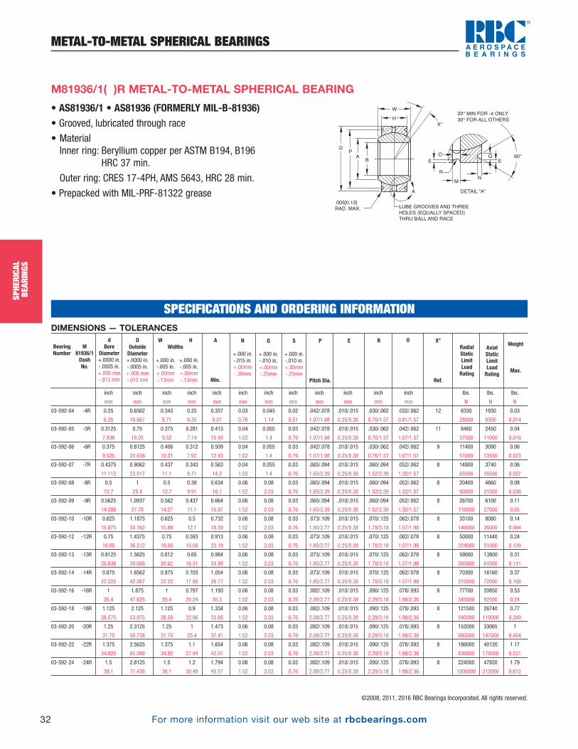
For more information visit our web site at rbcbearings.com
METAL-TO-METAL SPHERICAL BEARINGS
32
SPHE
RICA
LBE
ARIN
GS
©2008, 2011, 2016 RBC Bearings Incorporated. All rights reserved.
SPHE
RICA
LBE
ARIN
GS
• AS81936/1 • AS81936 (FORMERLY MIL-B-81936)• Grooved, lubricated through race
• MaterialInner ring: Beryllium copper per ASTM B194, B196
HRC 37 min.
Outer ring: CRES 17-4PH, AMS 5643, HRC 28 min.
• Prepacked with MIL-PRF-81322 grease
DP
A
A
60°S
Q
DETAIL “A”
NM
R
B
W
H
X°
LUBE GROOVES AND THREE
HOLES (EQUALLY SPACED)
THRU BALL AND RACE
.005[0.13]
RAD. MAX.
E
O
20° MIN FOR -4 ONLY
30° FOR ALL OTHERS
M81936/1( )R METAL-TO-METAL SPHERICAL BEARING
DIMENSIONS — TOLERANCES
inch inch inch inch inch inch inch inch inch inch inch inch lbs. lbs. lbs.
mm mm mm mm mm mm mm mm mm mm mm mm N N N
03-592-04 -4R 0.25 0.6562 0.343 0.25 0.357 0.03 0.045 0.02 .042/.078 .010/.015 .030/.062 .032/.062 12 6330 1930 0.03
6.35 16.667 8.71 6.35 9.07 0.76 1.14 0.51 1.07/1.98 0.25/0.38 0.76/1.57 0.81/1.57 28000 8500 0.014
03-592-05 -5R 0.3125 0.75 0.375 0.281 0.413 0.04 0.055 0.03 .042/.078 .010/.015 .030/.062 .042/.062 11 8460 2450 0.04
7.938 19.05 9.52 7.14 10.49 1.02 1.4 0.76 1.07/1.98 0.25/0.38 0.76/1.57 1.07/1.57 37500 11000 0.018
03-592-06 -6R 0.375 0.8125 0.406 0.312 0.509 0.04 0.055 0.03 .042/.078 .010/.015 .030/.062 .042/.062 9 11400 3090 0.06
9.525 20.638 10.31 7.92 12.93 1.02 1.4 0.76 1.07/1.98 0.25/0.38 0.76/1.57 1.07/1.57 51000 13500 0.023
03-592-07 -7R 0.4375 0.9062 0.437 0.343 0.563 0.04 0.055 0.03 .065/.094 .010/.015 .060/.094 .052/.062 8 14800 3740 0.06
11.112 23.017 11.1 8.71 14.3 1.02 1.4 0.76 1.65/2.39 0.25/0.38 1.52/2.39 1.32/1.57 65500 16500 0.027
03-592-08 -8R 0.5 1 0.5 0.39 0.634 0.06 0.08 0.03 .065/.094 .010/.015 .060/.094 .052/.062 8 20400 4860 0.08
12.7 25.4 12.7 9.91 16.1 1.52 2.03 0.76 1.65/2.39 0.25/0.38 1.52/2.39 1.32/1.57 90000 21500 0.036
03-592-09 -9R 0.5625 1.0937 0.562 0.437 0.664 0.06 0.08 0.03 .065/.094 .010/.015 .060/.094 .052/.062 8 26700 6100 0.11
14.288 27.78 14.27 11.1 16.87 1.52 2.03 0.76 1.65/2.39 0.25/0.38 1.52/2.39 1.32/1.57 118000 27000 0.05
03-592-10 -10R 0.625 1.1875 0.625 0.5 0.732 0.06 0.08 0.03 .073/.109 .010/.015 .070/.125 .062/.078 8 33100 8080 0.14
15.875 30.162 15.88 12.7 18.59 1.52 2.03 0.76 1.85/2.77 0.25/0.38 1.78/3.18 1.57/1.98 146000 36000 0.064
03-592-12 -12R 0.75 1.4375 0.75 0.593 0.913 0.06 0.08 0.03 .073/.109 .010/.015 .070/.125 .062/.078 8 50000 11440 0.24
19.05 36.512 19.05 15.06 23.19 1.52 2.03 0.76 1.85/2.77 0.25/0.38 1.78/3.18 1.57/1.98 224000 51000 0.109
03-592-13 -13R 0.8125 1.5625 0.812 0.65 0.984 0.06 0.08 0.03 .073/.109 .010/.015 .070/.125 .062/.078 8 59000 13800 0.31
20.638 39.688 20.62 16.51 24.99 1.52 2.03 0.76 1.85/2.77 0.25/0.38 1.78/3.18 1.57/1.98 260000 61000 0.141
03-592-14 -14R 0.875 1.6562 0.875 0.703 1.054 0.06 0.08 0.03 .073/.109 .010/.015 .070/.125 .062/.078 8 70300 16160 0.37
22.225 42.067 22.22 17.86 26.77 1.52 2.03 0.76 1.85/2.77 0.25/0.38 1.78/3.18 1.57/1.98 315000 72000 0.168
03-592-16 -16R 1 1.875 1 0.797 1.193 0.06 0.08 0.03 .082/.109 .010/.015 .090/.125 .078/.093 8 77700 20850 0.53
25.4 47.625 25.4 20.24 30.3 1.52 2.03 0.76 2.08/2.77 0.25/0.38 2.29/3.18 1.98/2.36 345000 92500 0.24
03-592-18 -18R 1.125 2.125 1.125 0.9 1.334 0.06 0.08 0.03 .082/.109 .010/.015 .090/.125 .078/.093 8 121500 26740 0.77
28.575 53.975 28.58 22.86 33.88 1.52 2.03 0.76 2.08/2.77 0.25/0.38 2.29/3.18 1.98/2.36 540000 119000 0.349
03-592-20 -20R 1.25 2.3125 1.25 1 1.473 0.06 0.08 0.03 .082/.109 .010/.015 .090/.125 .078/.093 8 152000 33065 1
31.75 58.738 31.75 25.4 37.41 1.52 2.03 0.76 2.08/2.77 0.25/0.38 2.29/3.18 1.98/2.36 680000 147000 0.454
03-592-22 -22R 1.375 2.5625 1.375 1.1 1.654 0.06 0.08 0.03 .082/.109 .010/.015 .090/.125 .078/.093 8 186000 40120 1.17
34.925 65.088 34.92 27.94 42.01 1.52 2.03 0.76 2.08/2.77 0.25/0.38 2.29/3.18 1.98/2.36 830000 178000 0.531
03-592-24 -24R 1.5 2.8125 1.5 1.2 1.794 0.06 0.08 0.03 .082/.109 .010/.015 .090/.125 .078/.093 8 224000 47820 1.79
38.1 71.438 38.1 30.48 45.57 1.52 2.03 0.76 2.08/2.77 0.25/0.38 2.29/3.18 1.98/2.36 1000000 212000 0.812
Weight
Max.
Axial Static Limit LoadRating
Radial Static Limit Load Rating
X°
Ref.
OREP
Pitch Dia.
DOutsideDiameter+.0000 in.-.0005 in.+.000 mm-.013 mm
dBore
Diameter+.0000 in.-.0005 in.+.000 mm-.013 mm
S
+.000 in.-.010 in.+.00mm-.25mm
Q
+.000 in.-.010 in.+.00mm-.25mm
N
+.000 in.-.015 in.+.00mm-.38mm
A
Min.
W HWidths
+.000 in. +.000 in.-.005 in. -.005 in.+.00mm +.00mm-.13mm -.13mm
BearingNumber
M81936/1DashNo.
SPECIFICATIONS AND ORDERING INFORMATION
PB_018_048_8-30-16_Pln_018_050.qxd 8/30/16 11:00 AM Page 32
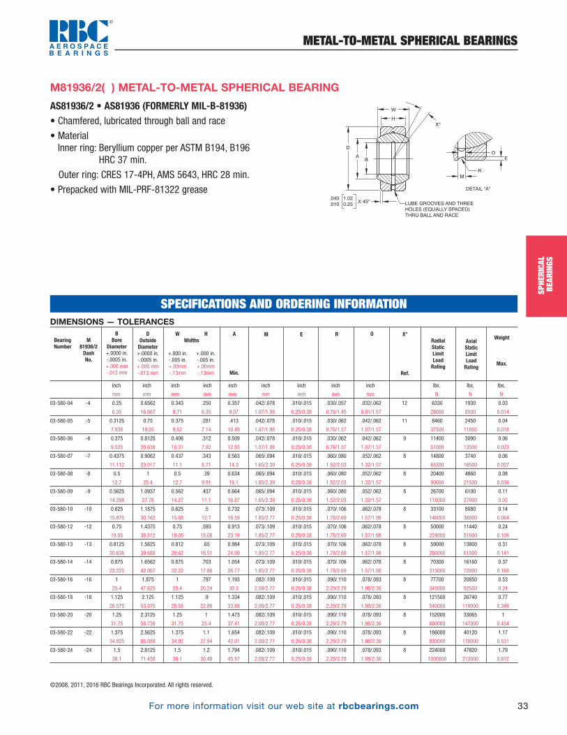
For more information visit our web site at rbcbearings.com
METAL-TO-METAL SPHERICAL BEARINGS
33
SPHE
RICA
LBE
ARIN
GS
©2008, 2011, 2016 RBC Bearings Incorporated. All rights reserved.
AS81936/2 • AS81936 (FORMERLY MIL-B-81936)• Chamfered, lubricated through ball and race
• MaterialInner ring: Beryllium copper per ASTM B194, B196
HRC 37 min.
Outer ring: CRES 17-4PH, AMS 5643, HRC 28 min.
• Prepacked with MIL-PRF-81322 grease
D
AB
W
H
X°
LUBE GROOVES AND THREE
HOLES (EQUALLY SPACED)
THRU BALL AND RACE
.040 1.02
.010 0.25X 45°
DETAIL “A”
M
R
O
E
M81936/2( ) METAL-TO-METAL SPHERICAL BEARING
DIMENSIONS — TOLERANCES
inch inch inch inch inch inch inch inch inch lbs. lbs. lbs.
mm mm mm mm mm mm mm mm mm N N N
03-580-04 -4 0.25 0.6562 0.343 .250 0.357 .042/.078 .010/.015 .030/.057 .032/.062 12 6330 1930 0.03
6.35 16.667 8.71 6.35 9.07 1.07/1.98 0.25/0.38 0.76/1.45 0.81/1.57 28000 8500 0.014
03-580-05 -5 0.3125 0.75 0.375 .281 .413 .042/.078 .010/.015 .030/.062 .042/.062 11 8460 2450 0.04
7.938 19.05 9.52 7.14 10.49 1.07/1.98 0.25/0.38 0.76/1.57 1.07/1.57 37500 11000 0.018
03-580-06 -6 0.375 0.8125 0.406 .312 0.509 .042/.078 .010/.015 .030/.062 .042/.062 9 11400 3090 0.06
9.525 20.638 10.31 7.92 12.93 1.07/1.98 0.25/0.38 0.76/1.57 1.07/1.57 51000 13500 0.023
03-580-07 -7 0.4375 0.9062 0.437 .343 0.563 .065/.094 .010/.015 .060/.080 .052/.062 8 14800 3740 0.06
11.112 23.017 11.1 8.71 14.3 1.65/2.39 0.25/0.38 1.52/2.03 1.32/1.57 65500 16500 0.027
03-580-08 -8 0.5 1 0.5 .39 0.634 .065/.094 .010/.015 .060/.080 .052/.062 8 20400 4860 0.08
12.7 25.4 12.7 9.91 16.1 1.65/2.39 0.25/0.38 1.52/2.03 1.32/1.57 90000 21500 0.036
03-580-09 -9 0.5625 1.0937 0.562 .437 0.664 .065/.094 .010/.015 .060/.080 .052/.062 8 26700 6100 0.11
14.288 27.78 14.27 11.1 16.87 1.65/2.39 0.25/0.38 1.52/2.03 1.32/1.57 118000 27000 0.05
03-580-10 -10 0.625 1.1875 0.625 .5 0.732 .073/.109 .010/.015 .070/.106 .062/.078 8 33100 8080 0.14
15.875 30.162 15.88 12.7 18.59 1.85/2.77 0.25/0.38 1.78/2.69 1.57/1.98 146000 36000 0.064
03-580-12 -12 0.75 1.4375 0.75 .593 0.913 .073/.109 .010/.015 .070/.106 .062/.078 8 50000 11440 0.24
19.05 36.512 19.05 15.06 23.19 1.85/2.77 0.25/0.38 1.78/2.69 1.57/1.98 224000 51000 0.109
03-580-13 -13 0.8125 1.5625 0.812 .65 0.984 .073/.109 .010/.015 .070/.106 .062/.078 8 59000 13800 0.31
20.638 39.688 20.62 16.51 24.99 1.85/2.77 0.25/0.38 1.78/2.69 1.57/1.98 260000 61000 0.141
03-580-14 -14 0.875 1.6562 0.875 .703 1.054 .073/.109 .010/.015 .070/.106 .062/.078 8 70300 16160 0.37
22.225 42.067 22.22 17.86 26.77 1.85/2.77 0.25/0.38 1.78/2.69 1.57/1.98 315000 72000 0.168
03-580-16 -16 1 1.875 1 .797 1.193 .082/.109 .010/.015 .090/.110 .078/.093 8 77700 20850 0.53
25.4 47.625 25.4 20.24 30.3 2.08/2.77 0.25/0.38 2.29/2.79 1.98/2.36 345000 92500 0.24
03-580-18 -18 1.125 2.125 1.125 .9 1.334 .082/.109 .010/.015 .090/.110 .078/.093 8 121500 26740 0.77
28.575 53.975 28.58 22.86 33.88 2.08/2.77 0.25/0.38 2.29/2.79 1.98/2.36 540000 119000 0.349
03-580-20 -20 1.25 2.3125 1.25 1 1.473 .082/.109 .010/.015 .090/.110 .078/.093 8 152000 33065 1
31.75 58.738 31.75 25.4 37.41 2.08/2.77 0.25/0.38 2.29/2.79 1.98/2.36 680000 147000 0.454
03-580-22 -22 1.375 2.5625 1.375 1.1 1.654 .082/.109 .010/.015 .090/.110 .078/.093 8 186000 40120 1.17
34.925 65.088 34.92 27.94 42.01 2.08/2.77 0.25/0.38 2.29/2.79 1.98/2.36 830000 178000 0.531
03-580-24 -24 1.5 2.8125 1.5 1.2 1.794 .082/.109 .010/.015 .090/.110 .078/.093 8 224000 47820 1.79
38.1 71.438 38.1 30.48 45.57 2.08/2.77 0.25/0.38 2.29/2.79 1.98/2.36 1000000 212000 0.812
Weight
Max.
Axial Static Limit Load Rating
Radial Static Limit Load Rating
X°
Ref.
OREMA
Min.
W HWidths
+.000 in. +.000 in.-.005 in. -.005 in.+.00mm +.00mm-.13mm -.13mm
DOutsideDiameter+.0000 in.-.0005 in.+.000 mm-.013 mm
BBore
Diameter+.0000 in.-.0005 in.+.000 mm-.013 mm
BearingNumber
M81936/2DashNo.
SPECIFICATIONS AND ORDERING INFORMATION
SPHE
RICA
LBE
ARIN
GSPB_018_048_8-30-16_Pln_018_050.qxd 8/30/16 11:00 AM Page 33
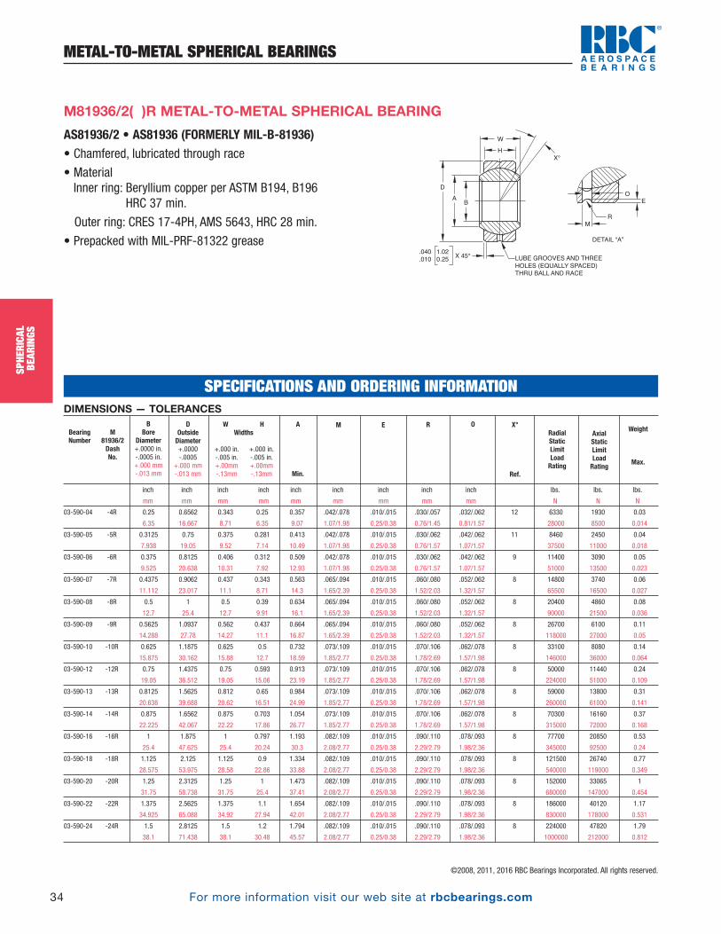
For more information visit our web site at rbcbearings.com
METAL-TO-METAL SPHERICAL BEARINGS
34
SPHE
RICA
LBE
ARIN
GS
©2008, 2011, 2016 RBC Bearings Incorporated. All rights reserved.
SPHE
RICA
LBE
ARIN
GS
AS81936/2 • AS81936 (FORMERLY MIL-B-81936)• Chamfered, lubricated through race
• MaterialInner ring: Beryllium copper per ASTM B194, B196
HRC 37 min.
Outer ring: CRES 17-4PH, AMS 5643, HRC 28 min.
• Prepacked with MIL-PRF-81322 grease
M81936/2( )R METAL-TO-METAL SPHERICAL BEARING
DIMENSIONS — TOLERANCES
inch inch inch inch inch inch inch inch inch lbs. lbs. lbs.
mm mm mm mm mm mm mm mm mm N N N
03-590-04 -4R 0.25 0.6562 0.343 0.25 0.357 .042/.078 .010/.015 .030/.057 .032/.062 12 6330 1930 0.03
6.35 16.667 8.71 6.35 9.07 1.07/1.98 0.25/0.38 0.76/1.45 0.81/1.57 28000 8500 0.014
03-590-05 -5R 0.3125 0.75 0.375 0.281 0.413 .042/.078 .010/.015 .030/.062 .042/.062 11 8460 2450 0.04
7.938 19.05 9.52 7.14 10.49 1.07/1.98 0.25/0.38 0.76/1.57 1.07/1.57 37500 11000 0.018
03-590-06 -6R 0.375 0.8125 0.406 0.312 0.509 .042/.078 .010/.015 .030/.062 .042/.062 9 11400 3090 0.05
9.525 20.638 10.31 7.92 12.93 1.07/1.98 0.25/0.38 0.76/1.57 1.07/1.57 51000 13500 0.023
03-590-07 -7R 0.4375 0.9062 0.437 0.343 0.563 .065/.094 .010/.015 .060/.080 .052/.062 8 14800 3740 0.06
11.112 23.017 11.1 8.71 14.3 1.65/2.39 0.25/0.38 1.52/2.03 1.32/1.57 65500 16500 0.027
03-590-08 -8R 0.5 1 0.5 0.39 0.634 .065/.094 .010/.015 .060/.080 .052/.062 8 20400 4860 0.08
12.7 25.4 12.7 9.91 16.1 1.65/2.39 0.25/0.38 1.52/2.03 1.32/1.57 90000 21500 0.036
03-590-09 -9R 0.5625 1.0937 0.562 0.437 0.664 .065/.094 .010/.015 .060/.080 .052/.062 8 26700 6100 0.11
14.288 27.78 14.27 11.1 16.87 1.65/2.39 0.25/0.38 1.52/2.03 1.32/1.57 118000 27000 0.05
03-590-10 -10R 0.625 1.1875 0.625 0.5 0.732 .073/.109 .010/.015 .070/.106 .062/.078 8 33100 8080 0.14
15.875 30.162 15.88 12.7 18.59 1.85/2.77 0.25/0.38 1.78/2.69 1.57/1.98 146000 36000 0.064
03-590-12 -12R 0.75 1.4375 0.75 0.593 0.913 .073/.109 .010/.015 .070/.106 .062/.078 8 50000 11440 0.24
19.05 36.512 19.05 15.06 23.19 1.85/2.77 0.25/0.38 1.78/2.69 1.57/1.98 224000 51000 0.109
03-590-13 -13R 0.8125 1.5625 0.812 0.65 0.984 .073/.109 .010/.015 .070/.106 .062/.078 8 59000 13800 0.31
20.638 39.688 20.62 16.51 24.99 1.85/2.77 0.25/0.38 1.78/2.69 1.57/1.98 260000 61000 0.141
03-590-14 -14R 0.875 1.6562 0.875 0.703 1.054 .073/.109 .010/.015 .070/.106 .062/.078 8 70300 16160 0.37
22.225 42.067 22.22 17.86 26.77 1.85/2.77 0.25/0.38 1.78/2.69 1.57/1.98 315000 72000 0.168
03-590-16 -16R 1 1.875 1 0.797 1.193 .082/.109 .010/.015 .090/.110 .078/.093 8 77700 20850 0.53
25.4 47.625 25.4 20.24 30.3 2.08/2.77 0.25/0.38 2.29/2.79 1.98/2.36 345000 92500 0.24
03-590-18 -18R 1.125 2.125 1.125 0.9 1.334 .082/.109 .010/.015 .090/.110 .078/.093 8 121500 26740 0.77
28.575 53.975 28.58 22.86 33.88 2.08/2.77 0.25/0.38 2.29/2.79 1.98/2.36 540000 119000 0.349
03-590-20 -20R 1.25 2.3125 1.25 1 1.473 .082/.109 .010/.015 .090/.110 .078/.093 8 152000 33065 1
31.75 58.738 31.75 25.4 37.41 2.08/2.77 0.25/0.38 2.29/2.79 1.98/2.36 680000 147000 0.454
03-590-22 -22R 1.375 2.5625 1.375 1.1 1.654 .082/.109 .010/.015 .090/.110 .078/.093 8 186000 40120 1.17
34.925 65.088 34.92 27.94 42.01 2.08/2.77 0.25/0.38 2.29/2.79 1.98/2.36 830000 178000 0.531
03-590-24 -24R 1.5 2.8125 1.5 1.2 1.794 .082/.109 .010/.015 .090/.110 .078/.093 8 224000 47820 1.79
38.1 71.438 38.1 30.48 45.57 2.08/2.77 0.25/0.38 2.29/2.79 1.98/2.36 1000000 212000 0.812
Weight
Max.
Axial Static Limit Load Rating
Radial Static Limit Load Rating
X°
Ref.
OREMDOutsideDiameter+.0000-.0005
+.000 mm-.013 mm
BBore
Diameter+.0000 in.-.0005 in.+.000 mm-.013 mm
A
Min.
W HWidths
+.000 in. +.000 in.-.005 in. -.005 in.+.00mm +.00mm-.13mm -.13mm
BearingNumber
M81936/2DashNo.
D
AB
W
H
X°
LUBE GROOVES AND THREE
HOLES (EQUALLY SPACED)
THRU BALL AND RACE
.040 1.02
.010 0.25X 45°
DETAIL “A”
M
R
O
E
SPECIFICATIONS AND ORDERING INFORMATION
PB_018_048_8-30-16_Pln_018_050.qxd 8/30/16 11:00 AM Page 34
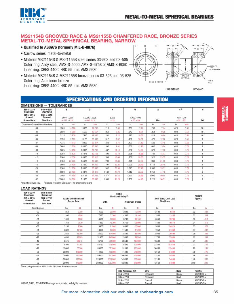
For more information visit our web site at rbcbearings.com
METAL-TO-METAL SPHERICAL BEARINGS
35
SPHE
RICA
LBE
ARIN
GS
©2008, 2011, 2016 RBC Bearings Incorporated. All rights reserved.
• Qualified to AS8976 (formerly MIL-B-8976) • Narrow series, metal-to-metal
• Material MS21154S & MS21155S steel series 03-503 and 03-505Outer ring: Alloy steel, AMS-S-5000, AMS-S-6758 or AMS-S-6050Inner ring: CRES 440C, HRC 55 min. AMS 5630
• Material MS21154B & MS21155B bronze series 03-523 and 03-525Outer ring: Aluminum bronzeInner ring: CRES 440C, HRC 55 min. AMS 5630
MS21154B GROOVED RACE & MS21155B CHAMFERED RACE, BRONZE SERIESMETAL-TO-METAL SPHERICAL BEARING, NARROW
DIMENSIONS — TOLERANCES
Chamfered/Grooved Dash Numbers in. mm in. mm in. mm in. mm in. mm in. mm
-03 .1900 4.826 .5625 14.288 .218 5.54 .281 7.14 .293 7.44 .020 0.51 10
-04 .2500 6.350 .6562 16.667 .250 6.35 .343 8.71 .364 9.25 .020 0.51 10
-05 .3125 7.938 .7500 19.050 .281 7.14 .375 9.52 .419 10.64 .020 0.51 10
-06 .3750 9.525 .8125 20.638 .312 7.92 .406 10.31 .475 12.06 .020 0.51 9
-07 .4375 11.113 .9062 23.017 .343 8.71 .437 11.10 .530 13.46 .020 0.51 8
-08 .5000 12.700 1.0000 25.400 .390 9.91 .500 12.70 .600 15.24 .030 0.76 8
-09 .5625 14.288 1.0937 27.780 .437 11.10 .562 14.27 .670 17.02 .030 0.76 8
-10 .6250 15.875 1.1875 30.163 .500 12.70 .625 15.88 .739 18.77 .030 0.76 8
-12 .7500 19.050 1.4375 36.513 .593 15.06 .750 19.05 .920 23.37 .030 0.76 8
-14 .8750 22.225 1.5625 39.688 .703 17.86 .875 22.22 .980 24.89 .030 0.76 8
-16 1.0000 25.400 1.7500 44.450 .797 20.24 1.000 25.40 1.118 28.40 .030 0.76 9
-20 1.2500 31.750 2.0000 50.800 .942 23.93 1.093 27.76 1.390 35.31 .030 0.76 6
-24 1.5000 38.100 2.4375 61.913 1.130 28.70 1.312 33.32 1.750 44.45 .030 0.76 6
-28 1.7500 44.450 2.8125 71.438 1.317 33.45 1.531 38.89 2.000 50.80 .030 0.76 6
-32 2.0000 50.800 3.1875 80.963 1.505 38.23 1.750 44.45 2.225 56.51 .030 0.76 6(1)Chamfered Type only. (2)Grooved Type only. See page 17 for groove dimensions
X°
Ref.
C(1)
+.020, -.010 +.51, -.25
A
Min.
W
+.000, -.002 +.00, -.05
H
±.005 ±.13
D
+.0000, -.0005 +.000, .013
B
+.0000, -.0005 +.000, -.013
BLN-x-2210 ChamferedBLN-x-2215Grooved
Bronze Race
BSN-x-2211 ChamferedBSN-x-2216GroovedSteel Race
LOAD RATINGS
Dash Numbers lbs. N lbs. N lbs. N lbs. N lbs. kg
-03 850 3780 4600 20500 2800 12500 2100 9340 .02 .009
-04 1100 4890 7080 31500 4300 19100 2800 12455 .02 .009
-05 1400 6230 8500 37800 5200 23100 3550 15790 .03 .014
-06 1760 7830 11050 49200 6750 30000 4400 19570 .04 .018
-07 2150 9560 13900 61800 8500 37800 5400 24020 .05 .023
-08 2800 12455 18850 83800 11500 51200 7050 31360 .07 .032
-09 3550 15790 25500 114000 15600 69400 8900 39590 .09 .041
-10 4650 20685 31900 142000 19500 86700 11700 52040 .12 .054
-12 6575 29245 46750 208000 28500 127000 16500 73395 .21 .095
-14 9300 41365 62750 279000 38300 170000 23300 103640 .27 .122
-16 12000 53380 83350 371000 51000 227000 30000 133450 .29 .131
-20 38000 170000 114000 506000 71000 316000 12160 54000 .39 .176
-24 38000 170000 169000 752000 106000 470000 12160 54000 .96 .432
-28 38000 170000 228000 1016000 143000 635000 12160 54000 1.48 .666
-32 38000 170000 292000 1297000 182000 810000 12160 54000 2.10 .945(1)Load ratings based on AS21155 for CRES and Aluminum bronze
WeightApprox.Axial Static Limit Load
Steel Race
RadialLimit Load Rating(1)
CRES Aluminum Bronze Axial Static Limit Load
Bronze Race
BLN-x-2210 ChamferedBLN-x-2215Grooved
Bronze Race
BSN-x-2211 ChamferedBSN-x-2216GroovedSteel Race
SPECIFICATIONS AND ORDERING INFORMATION
RBC Aerospace P/N Style Race Part No.BLN-x-2210 Chamfered Bronze MS21155B-xBSN-x-2211 Chamfered Steel MS21155S-xBLN-x-2215 Grooved Bronze MS21154B-x BSN-x-2216 Grooved Steel MS21154S-x
Chamfered Grooved
W
HX°X°
C X 45° CHAMFER
LUBRICATION
GROOVE
OPTIONAL
B
D
R OR
.005 R
MAX.
.005
.015
45° CHAMFER
W
H
SPHE
RICA
LBE
ARIN
GSPB_018_048_8-30-16_Pln_018_050.qxd 8/30/16 11:00 AM Page 35

For more information visit our web site at rbcbearings.com
METAL-TO-METAL SPHERICAL BEARINGS
36
SPHE
RICA
LBE
ARIN
GS
©2008, 2011, 2016 RBC Bearings Incorporated. All rights reserved.
SPHE
RICA
LBE
ARIN
GS
European Standards • Swaged series, Corrosion resistant steel
• All dimensions are metric
• MaterialOuter ring: CRES 17-4PH, EN3490 or EN3161Inner ring: CRES 440C, EN2030
• Chamfered or grooved type
• Lubrication holes and grooves on the race
• Lubrication holes and grooves on the ball
EN2335
Bearing configuration Part number designations and options
EN2335 AP 12 ERT 12mm bore with Nato grease G354/Mil-G-23827, reduced internal clearance, no lubrication holes and grooves, swaging grooves and passivated per ISO8075
Suffix A is for grease type A = Nato G354/Mil-G-23827 or B = Nato G395/Mil-G-81322
Suffix P is for radial and axial play P = Reduced internal clearance or N = Normal internal clearance
Bore size 12 = 12mm bore
Suffix E is for type of lubrication E = No lubrication holes and grooves, F = Lubrication holes and grooves in the ball
G = Lubrication holes and grooves in the race
Suffix R is for type of mounting R = Grooved type (sizes 12 and higher only) or S = Chamfered type
Suffix T is for passivation T = Passivation per ISO8075 or Blank = No passivation
SPECIFICATIONS AND ORDERING INFORMATION
D
AB
W
H
X°
LUBE GROOVES AND THREE
HOLES (EQUALLY SPACED)
THRU BALL AND RACE
.040 1.02
.010 0.25X 45°
PB_018_048_8-30-16_Pln_018_050.qxd 8/30/16 11:00 AM Page 36
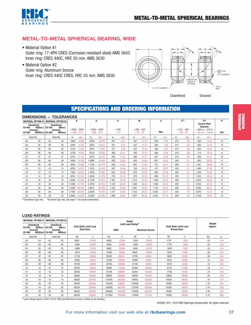
For more information visit our web site at rbcbearings.com
METAL-TO-METAL SPHERICAL BEARINGS
37
SPHE
RICA
LBE
ARIN
GS
©2008, 2011, 2016 RBC Bearings Incorporated. All rights reserved.
Chamfered Grooved
W
HX°X°
C X 45° CHAMFER
LUBRICATION
GROOVE
OPTIONAL
B
D
R OR
.005 R
MAX.
.005
.015
45° CHAMFER
W
H
DIMENSIONS — TOLERANCES
Dash No. Dash No. in. mm in. mm in. mm in. mm in. mm in. mm in. mm
-03 03 -03 03 .1900 4.826 .6250 15.875 .327 8.31 .437 11.10 .300 7.62 .015 .38 .563 14.30 15
-04 04 -04 04 .2500 6.350 .6250 15.875 .327 8.31 .437 11.10 .300 7.62 .015 .38 .563 14.30 15
-05 05 -05 05 .3125 7.938 .6875 17.462 .317 8.05 .437 11.10 .360 9.14 .015 .38 .625 15.87 14
-06 06 -06 06 .3750 9.525 .8125 20.638 .406 10.31 .500 12.70 .466 11.84 .015 .38 .714 18.14 8
-07 07 -07 07 .4375 11.112 .9375 23.813 .442 11.23 .562 14.27 .537 13.64 .015 .38 .839 21.31 10
-08 08 -08 08 .5000 12.700 1.0000 25.400 .505 12.83 .625 15.88 .607 15.42 .020 .51 .902 22.91 9
-09 09 -09 09 .5625 14.288 1.1250 28.575 .536 13.61 .687 17.45 .721 18.31 .020 .51 1.027 26.09 10
-10 10 -10 10 .6250 15.875 1.1875 30.163 .567 14.40 .750 19.05 .747 18.97 .020 .51 1.089 27.66 12
-12 12 -12 12 .7500 19.050 1.3750 34.925 .630 16.00 .875 22.22 .845 21.46 .020 .51 1.253 31.83 13
-14 14 -14 14 .8750 22.225 1.6250 41.275 .755 19.18 .875 22.22 .995 25.27 .020 .51 1.503 38.18 6
-16 16 -16 16 1.0000 25.400 2.1250 53.975 1.005 25.53 1.375 34.92 1.269 32.23 .020 .51 2.003 50.88 12
-20 20 -20 20 1.2500 31.750 2.3750 60.325 1.130 28.70 1.500 38.10 1.500 38.10 .020 .51 2.253 57.23 12
-24 24 -24 24 1.5000 38.100 2.6875 68.263 1.223 31.06 1.687 42.85 1.750 44.45 .030 .76 2.565 65.15 13
-28 28 -28 28 1.7500 44.450 3.0000 76.200 1.317 33.45 1.812 46.02 2.050 52.07 .030 .76 2.878 73.10 12
-32 32 -32 32 2.0000 50.800 3.2500 82.550 1.380 35.05 1.937 49.20 2.250 57.15 .030 .76 3.128 79.45 12(1)Chamfered Type only. (2)Grooved Type only. See page 17 for groove dimensions.
MATERIAL OPTION #2
Chamfered03-524 WBxxJ
Grooved03-526 WBGxxJ
MATERIAL OPTION #1
Chamfered03-504 WSSxxJ
Grooved03-506 WSSGxxJ
X°
Ref.
P(2)
Groove PitchDiameter
+.000 in., -.010 in. +.00 mm, -.25mm
C(1)
+.015, -.000 +.38, -.00
A
Min.
W
+.000, -.002 +.00, -.05
H
±.005 ±.13
D
+.0000, -.0005 +.000, -.013
B
+.0000, -.0005 +.000, -.013
LOAD RATINGS
Dash No. Dash No. lbf. N lbf. N lbf. N lbf. N lbs. kg
-03 03 -03 03 4900 21600 8400 37000 5300 23400 1770 7800 .03 .014
-04 04 -04 04 4900 21600 8400 37000 5300 23400 1770 7800 .03 .014
-05 05 -05 05 6060 27000 9600 43000 6000 26700 1640 7350 .03 .014
-06 06 -06 06 8310 36500 15400 69000 9600 42800 2630 11600 .05 .023
-07 07 -07 07 11750 52000 20200 90000 12700 56300 3650 16300 .08 .036
-08 08 -08 08 14950 65500 27000 120000 16900 75000 4970 22000 .10 .045
-09 09 -09 09 18100 80000 33700 150000 21100 94000 5370 24000 .14 .063
-10 10 -10 10 20250 90000 38900 173000 24300 108000 6130 27500 .16 .072
-12 12 -12 12 26200 116000 51500 230000 32200 143000 7730 34500 .23 .104
-14 14 -14 14 33600 150000 68800 306000 43000 191000 10800 48000 .35 .158
-16 16 -16 16 56250 250000 127000 563000 79000 352000 19300 86500 .97 .437
-20 20 -20 20 56250 250000 163000 726000 102000 454000 19300 86500 1.10 .495
-24 24 -24 24 56250 250000 203000 901000 127000 563000 19300 86500 1.45 .653
-28 28 -28 28 56250 250000 246000 1095000 154000 685000 19300 86500 1.85 .833
-32 32 -32 32 56250 250000 277000 1234000 173000 771000 19300 86500 2.15 .968(1)Load ratings based on AS21155 for CRES and Aluminum bronze. Limited by pin bending.
MATERIAL OPTION #2
Chamfered03-524 WBxxJ
Grooved03-526 WBGxxJ
MATERIAL OPTION #1
Chamfered03-504 WSSxxJ
Grooved03-506 WSSGxxJ
WeightApprox.Axial Static Limit Load
Bronze Race
RadialLimit Load Rating(1)
CRES Aluminum Bronze Axial Static Limit Load
Steel Race
SPECIFICATIONS AND ORDERING INFORMATION
• Material Option #1Outer ring: 17-4PH CRES (Corrosion resistant steel) AMS 5643Inner ring: CRES 440C, HRC 55 min. AMS 5630
• Material Option #2Outer ring: Aluminum bronzeInner ring: CRES 440C CRES, HRC 55 min. AMS 5630
METAL-TO-METAL SPHERICAL BEARING, WIDE
SPHE
RICA
LBE
ARIN
GSPB_018_048_8-30-16_Pln_018_050.qxd 8/30/16 11:00 AM Page 37
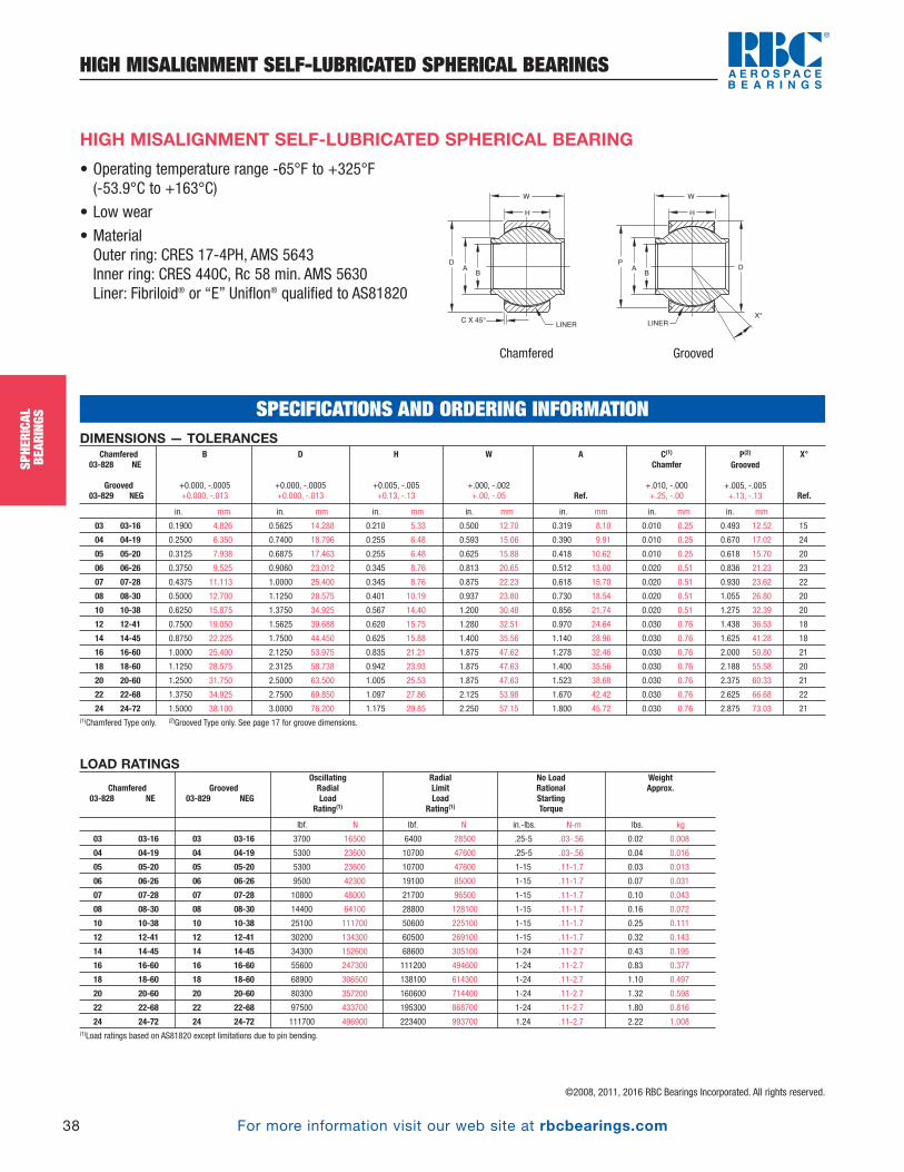
For more information visit our web site at rbcbearings.com
HIGH MISALIGNMENT SELF-LUBRICATED SPHERICAL BEARINGS
38
SPHE
RICA
LBE
ARIN
GS
©2008, 2011, 2016 RBC Bearings Incorporated. All rights reserved.
SPHE
RICA
LBE
ARIN
GS
• Operating temperature range -65°F to +325°F (-53.9°C to +163°C)
• Low wear
• MaterialOuter ring: CRES 17-4PH, AMS 5643Inner ring: CRES 440C, Rc 58 min. AMS 5630Liner: Fibriloid® or “E” Uniflon® qualified to AS81820
DA
B
W
H
C X 45°
C
D
LINER
PA
B
W
H
LINER
X°
HIGH MISALIGNMENT SELF-LUBRICATED SPHERICAL BEARING
DIMENSIONS — TOLERANCES
in. mm in. mm in. mm in. mm in. mm in. mm in. mm
03 03-16 0.1900 4.826 0.5625 14.288 0.210 5.33 0.500 12.70 0.319 8.10 0.010 0.25 0.493 12.52 15
04 04-19 0.2500 6.350 0.7400 18.796 0.255 6.48 0.593 15.06 0.390 9.91 0.010 0.25 0.670 17.02 24
05 05-20 0.3125 7.938 0.6875 17.463 0.255 6.48 0.625 15.88 0.418 10.62 0.010 0.25 0.618 15.70 20
06 06-26 0.3750 9.525 0.9060 23.012 0.345 8.76 0.813 20.65 0.512 13.00 0.020 0.51 0.836 21.23 23
07 07-28 0.4375 11.113 1.0000 25.400 0.345 8.76 0.875 22.23 0.618 15.70 0.020 0.51 0.930 23.62 22
08 08-30 0.5000 12.700 1.1250 28.575 0.401 10.19 0.937 23.80 0.730 18.54 0.020 0.51 1.055 26.80 20
10 10-38 0.6250 15.875 1.3750 34.925 0.567 14.40 1.200 30.48 0.856 21.74 0.020 0.51 1.275 32.39 20
12 12-41 0.7500 19.050 1.5625 39.688 0.620 15.75 1.280 32.51 0.970 24.64 0.030 0.76 1.438 36.53 18
14 14-45 0.8750 22.225 1.7500 44.450 0.625 15.88 1.400 35.56 1.140 28.96 0.030 0.76 1.625 41.28 18
16 16-60 1.0000 25.400 2.1250 53.975 0.835 21.21 1.875 47.62 1.278 32.46 0.030 0.76 2.000 50.80 21
18 18-60 1.1250 28.575 2.3125 58.738 0.942 23.93 1.875 47.63 1.400 35.56 0.030 0.76 2.188 55.58 20
20 20-60 1.2500 31.750 2.5000 63.500 1.005 25.53 1.875 47.63 1.523 38.68 0.030 0.76 2.375 60.33 21
22 22-68 1.3750 34.925 2.7500 69.850 1.097 27.86 2.125 53.98 1.670 42.42 0.030 0.76 2.625 66.68 22
24 24-72 1.5000 38.100 3.0000 76.200 1.175 29.85 2.250 57.15 1.800 45.72 0.030 0.76 2.875 73.03 21(1)Chamfered Type only. (2)Grooved Type only. See page 17 for groove dimensions.
P(2)
Grooved
+.005, -.005 +.13, -.13
X°
Ref.
C(1)
Chamfer
+.010, -.000 +.25, -.00
A
Ref.
W
+.000, -.002 +.00, -.05
H
+0.005, -.005 +0.13, -.13
D
+0.000, -.0005 +0.000, -.013
B
+0.000, -.0005 +0.000, -.013
Chamfered03-828 NE
Grooved03-829 NEG
LOAD RATINGS
lbf. N lbf. N in.-lbs. N-m lbs. kg
03 03-16 03 03-16 3700 16500 6400 28500 .25-5 .03-.56 0.02 0.008
04 04-19 04 04-19 5300 23600 10700 47600 .25-5 .03-.56 0.04 0.016
05 05-20 05 05-20 5300 23600 10700 47600 1-15 .11-1.7 0.03 0.013
06 06-26 06 06-26 9500 42300 19100 85000 1-15 .11-1.7 0.07 0.031
07 07-28 07 07-28 10800 48000 21700 96500 1-15 .11-1.7 0.10 0.043
08 08-30 08 08-30 14400 64100 28800 128100 1-15 .11-1.7 0.16 0.072
10 10-38 10 10-38 25100 111700 50600 225100 1-15 .11-1.7 0.25 0.111
12 12-41 12 12-41 30200 134300 60500 269100 1-15 .11-1.7 0.32 0.143
14 14-45 14 14-45 34300 152600 68600 305100 1-24 .11-2.7 0.43 0.195
16 16-60 16 16-60 55600 247300 111200 494600 1-24 .11-2.7 0.83 0.377
18 18-60 18 18-60 68900 306500 138100 614300 1-24 .11-2.7 1.10 0.497
20 20-60 20 20-60 80300 357200 160600 714400 1-24 .11-2.7 1.32 0.598
22 22-68 22 22-68 97500 433700 195300 868700 1-24 .11-2.7 1.80 0.816
24 24-72 24 24-72 111700 496900 223400 993700 1.24 .11-2.7 2.22 1.008(1)Load ratings based on AS81820 except limitations due to pin bending.
WeightApprox.
No LoadRationalStartingTorque
RadialLimitLoad
Rating(1)
OscillatingRadialLoad
Rating(1)
Chamfered03-828 NE
Grooved03-829 NEG
Chamfered Grooved
SPECIFICATIONS AND ORDERING INFORMATION
PB_018_048_8-30-16_Pln_018_050.qxd 8/30/16 11:00 AM Page 38

For more information visit our web site at rbcbearings.com
HIGH MISALIGNMENT SELF-LUBRICATED SPHERICAL BEARINGS
39
SPHE
RICA
LBE
ARIN
GS
©2008, 2011, 2016 RBC Bearings Incorporated. All rights reserved.
European Standards • All dimensions are metric
• Extended inner ring
• MaterialOuter ring: CRES 17-4PH, AMS 5643
Inner ring: CRES 440C, AMS 5630/EN2030
Liner: Qualified to AS81820
EN2501 HIGH-MISALIGNMENT SELF-LUBRICATED SPHERICAL BEARING
Bearing configuration Part number designations for a 8mm bore spherical bearing
Basic P/N EN2501-08
SPECIFICATIONS AND ORDERING INFORMATION
DP
A
A
60° ± 1°
DETAIL A
SCALE 6 : 1
N
R
B
W
HK
.008[0.20]RAD. MAX. LINER
SPHE
RICA
LBE
ARIN
GSPB_018_048_8-30-16_Pln_018_050.qxd 8/30/16 11:00 AM Page 39
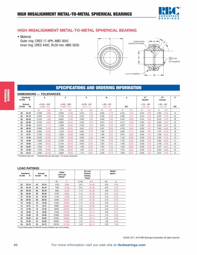
For more information visit our web site at rbcbearings.com
HIGH MISALIGNMENT METAL-TO-METAL SPHERICAL BEARINGS
40
SPHE
RICA
LBE
ARIN
GS
©2008, 2011, 2016 RBC Bearings Incorporated. All rights reserved.
SPHE
RICA
LBE
ARIN
GS
DIMENSIONS — TOLERANCES
in. mm in. mm in. mm in. mm in. mm in. mm in. mm
03 03-16 0.1900 4.826 0.5625 14.288 0.210 5.33 0.500 12.70 0.319 8.10 0.010 0.25 0.493 12.52 15
04 04-19 0.2500 6.350 0.7400 18.796 0.255 6.48 0.593 15.06 0.390 9.91 0.010 0.25 0.670 17.02 24
05 05-20 0.3125 7.938 0.6875 17.463 0.255 6.48 0.625 15.88 0.418 10.62 0.010 0.25 0.618 15.70 20
06 06-26 0.3750 9.525 0.9060 23.012 0.345 8.76 0.813 20.65 0.512 13.00 0.020 0.51 0.836 21.23 23
07 07-28 0.4375 11.113 1.0000 25.400 0.345 8.76 0.875 22.23 0.618 15.70 0.020 0.51 0.930 23.62 22
08 08-30 0.5000 12.700 1.1250 28.575 0.401 10.19 0.937 23.80 0.730 18.54 0.020 0.51 1.055 26.80 20
10 10-38 0.6250 15.875 1.3750 34.925 0.567 14.40 1.200 30.48 0.856 21.74 0.020 0.51 1.275 32.39 20
12 12-41 0.7500 19.050 1.5625 39.688 0.620 15.75 1.280 32.51 0.970 24.64 0.030 0.76 1.438 36.53 18
14 14-45 0.8750 22.225 1.7500 44.450 0.625 15.88 1.400 35.56 1.140 28.96 0.030 0.76 1.625 41.28 18
16 16-60 1.0000 25.400 2.1250 53.975 0.835 21.21 1.875 47.62 1.278 32.46 0.030 0.76 2.000 50.80 21
18 18-60 1.1250 28.575 2.3125 58.738 0.942 23.93 1.875 47.63 1.400 35.56 0.030 0.76 2.188 55.58 20
20 20-60 1.2500 31.750 2.5000 63.500 1.005 25.53 1.875 47.63 1.523 38.68 0.030 0.76 2.375 60.33 21
22 22-68 1.3750 34.925 2.7500 69.850 1.097 27.86 2.125 53.98 1.670 42.42 0.030 0.76 2.625 66.68 22
24 24-72 1.5000 38.100 3.0000 76.200 1.175 29.85 2.250 57.15 1.800 45.72 0.030 0.76 2.875 73.03 21(1)Chamfered Type only. (2)Grooved Type only. See page 17 for groove dimensions.
P(2)
Grooved
+.005, -.005 +.13, -.13
X°
Ref.
C(1)
Chamfer
+.010, -.000 +.25, -.00
A
Ref.
W
+.000, -.002 +.00, -.05
H
+0.005, -.005 +0.13, -.13
D
+0.000, -.0005 +0.000, -.013
B
+0.000, -.0005 +0.000, -.013
Chamfered03-508 N
Grooved03-528 NG
• MaterialOuter ring: CRES 17-4PH, AMS 5643Inner ring: CRES 440C, Rc58 min. AMS 5630
C X 45° CHAMFER
D
W
HX°
B
LUBRICATION
GROOVE OPTIONAL
R OR.005
.015
45° CHAMFER
HIGH MISALIGNMENT METAL-TO-METAL SPHERICAL BEARING
LOAD RATINGS
lbf. N in.-lbs. N-m lbs. kg
03 03-16 03 03-16 4100 18200 .25-5 .03-.56 0.02 0.008
04 04-19 04 04-19 7000 31100 .25-5 .03-.56 0.04 0.016
05 05-20 05 05-20 8800 39100 1-15 .03-.90 0.03 0.013
06 06-26 06 06-26 15700 69800 1-15 .03-.90 0.07 0.031
07 07-28 07 07-28 17700 78700 1-15 .03-.90 0.10 0.043
08 08-30 08 08-30 23400 104100 1-15 .03-.90 0.16 0.072
10 10-38 10 10-38 41400 184200 1-15 .03-.90 0.25 0.111
12 12-41 12 12-41 49900 222000 1-15 .03-.90 0.32 0.143
14 14-45 14 14-45 56000 249100 1-24 .03-1.4 0.43 0.195
16 16-60 16 16-60 91600 407500 1-24 .03-1.4 0.83 0.377
18 18-60 18 18-60 113600 505300 1-24 .03-1.4 1.10 0.497
20 20-60 20 20-60 132300 588500 1-24 .03-1.4 1.32 0.598
22 22-68 22 22-68 160400 713500 1-24 .03-1.4 1.80 0.816
24 24-72 24 24-72 183700 817100 1-24 .03-1.4 2.22 1.008(1)Load ratings based on AS81820 except limitations due to pin bending.
Grooved03-528 NG
WeightApprox.
No LoadRationalStartingTorque
RadialLimit LoadRating(1)
Chamfered03-508 N
SPECIFICATIONS AND ORDERING INFORMATION
PB_018_048_8-30-16_Pln_018_050.qxd 8/30/16 11:00 AM Page 40
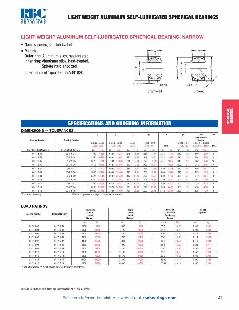
For more information visit our web site at rbcbearings.com
LIGHT WEIGHT ALUMINUM SELF-LUBRICATED SPHERICAL BEARINGS
41
SPHE
RICA
LBE
ARIN
GS
©2008, 2011, 2016 RBC Bearings Incorporated. All rights reserved.
• Narrow series, self-lubricated
• MaterialOuter ring: Aluminum alloy, heat-treatedInner ring: Aluminum alloy, heat-treated,
Sphere hard anodized
Liner: Fibriloid® qualified to AS81820
LIGHT WEIGHT ALUMINUM SELF-LUBRICATED SPHERICAL BEARING, NARROW
DIMENSIONS — TOLERANCES
Chamfered Part Numbers Grooved Part Numbers in. mm in. mm in. mm in. mm in. mm in. mm in. mm
03-713-03 03-715-03 .1900 4.826 .5625 14.288 .218 5.54 .281 7.14 .293 7.44 .010 .25 .500 12.70 10
03-713-04 03-715-04 .2500 6.350 .6562 16.667 .250 6.35 .343 8.71 .364 9.25 .010 .25 .594 15.09 10
03-713-05 03-715-05 .3125 7.938 .7500 19.050 .281 7.14 .375 9.52 .461 10.64 .010 .25 .660 16.76 10
03-713-06 03-715-06 .3750 9.525 .8125 20.638 .312 7.92 .406 10.31 .475 12.06 .020 .51 .712 18.08 9
03-713-07 03-715-07 .4375 11.112 .9062 23.017 .343 8.71 .437 11.10 .530 13.46 .020 .51 .806 20.47 8
03-713-08 03-715-08 .5000 12.700 1.0000 25.400 .390 9.91 .500 12.70 .600 15.24 .020 .51 .876 22.25 8
03-713-09 03-715-09 .5625 14.288 1.0937 27.780 .437 11.10 .562 14.27 .670 17.02 .020 .51 .970 24.64 8
03-713-10 03-715-10 .6250 15.875 1.1875 30.162 .500 12.70 .625 15.88 .739 18.77 .020 .51 1.063 27.00 8
03-713-12 03-715-12 .7500 19.050 1.4375 36.512 .593 15.06 .750 19.05 .920 23.37 .030 .76 1.313 33.35 8
03-713-14 03-715-14 .8750 22.225 1.5625 39.688 .703 17.86 .875 22.22 .980 24.89 .030 .76 1.438 36.53 8
03-713-16 03-715-16 1.0000 25.400 1.7500 44.450 .797 20.24 1.000 25.40 1.118 28.40 .030 .76 1.626 41.30 9(1)Chamfered Type only. (2)Grooved Type only. See page 17 for groove dimensions.
X°
Ref.
P(2)
Groove PitchDiameter
+.000 in., -.008 in. +.00 mm, -.20mm
C(1)
+.010, -.000 +.25, -.00
A
Min.
W
+.000, -.002 +.00, -.05
H
±.005 ±.13
D
+.0000, -.0005 +.000, -.013
B
+.0000, -.0005 +.000, -.013
Bearing Number Bearing Number
LOAD RATINGS
lbs. N lbs. N in.-lbs. N-m lbs. kg
03-713-03 03-715-03 1500 6700 3050 13600 .25-5 .03-.56 0.005 0.002
03-713-04 03-715-04 2320 10400 4120 18400 .25-5 .03-.56 0.008 0.004
03-713-05 03-715-05 3200 14300 5700 25400 .25-8 .03-.90 0.011 0.005
03-713-06 03-715-06 3800 17000 6780 30200 .25-8 .03-.90 0.014 0.006
03-713-07 03-715-07 4800 21500 8360 37200 .25-8 .03-.90 0.018 0.008
03-713-08 03-715-08 6820 30400 11000 49000 .25-8 .03-.90 0.025 0.011
03-713-09 03-715-09 8800 39200 14100 63000 .25-8 .03-.90 0.033 0.015
03-713-10 03-715-10 10800 48000 18100 80500 .25-8 .03-.90 0.050 0.023
03-713-12 03-715-12 16800 75000 28500 127000 .25-8 .03-.90 0.080 0.036
03-713-14 03-715-14 22000 98000 35400 157500 .25-12 .03-1.4 0.100 0.045
03-713-16 03-715-16 29000 129000 46300 206000 .25-12 .03-1.4 0.140 0.063(1)Load ratings based on AS81820 with reduction for aluminum materials.
WeightApprox.
No Load RotationalBreakaway Torque
RadialLimitLoad
Rating(1)
OscillatingRadialLoad
Rating(1)Bearing Number Bearing Number
SPECIFICATIONS AND ORDERING INFORMATION
A B
LINER
G
W
H
C X 45° X°
PDA
B
LINER
W
H
D
Chamfered Grooved
SPHE
RICA
LBE
ARIN
GSPB_018_048_8-30-16_Pln_018_050.qxd 8/30/16 11:00 AM Page 41

For more information visit our web site at rbcbearings.com
LIGHT WEIGHT ALUMINUM SELF-LUBRICATED SPHERICAL BEARINGS
42
SPHE
RICA
LBE
ARIN
GS
©2008, 2011, 2016 RBC Bearings Incorporated. All rights reserved.
SPHE
RICA
LBE
ARIN
GS
• Wide series, self-lubricated
• MaterialOuter ring: Aluminum Alloy, Heat-treatedInner ring: Aluminum Alloy, Heat-treated, Sphere hard anodizedLiner: Fibriloid® qualified to AS81820
LIGHT WEIGHT ALUMINUM SELF-LUBRICATED SPHERICAL BEARING, WIDE
DIMENSIONS — TOLERANCES
Chamfered Part Numbers Grooved Part Numbers in. mm in. mm in. mm in. mm in. mm in. mm in. mm
03-714-03 03-716-03 .1900 4.826 .6250 15.875 .327 8.31 .437 11.10 .300 7.62 .010 .25 .563 14.30 15
03-714-04 03-716-04 .2500 6.350 .6250 15.875 .327 8.31 .437 11.10 .300 7.62 .010 .25 .563 14.30 15
03-714-05 03-716-05 .3125 7.938 .6875 17.462 .317 8.05 .437 11.10 .360 9.14 .010 .25 .625 15.88 14
03-714-06 03-716-06 .3750 9.525 .8125 20.638 .406 10.31 .500 12.70 .466 11.84 .020 .51 .712 18.08 8
03-714-07 03-716-07 .4375 11.112 .9062 23.017 .442 11.23 .562 14.27 .537 13.64 .020 .51 .806 20.47 10
03-714-08 03-716-08 .5000 12.700 1.0000 25.400 .505 12.83 .625 15.88 .607 15.42 .020 .51 .900 22.86 9
03-714-09 03-716-09 .5625 14.288 1.1250 28.575 .536 13.61 .687 17.45 .721 18.31 .020 .51 1.025 26.04 10
03-714-10 03-716-10 .6250 15.875 1.1875 30.162 .567 14.40 .750 19.05 .747 18.97 .020 .51 1.087 27.61 12
03-714-12 03-716-12 .7500 19.050 1.3750 34.925 .630 16.00 .875 22.22 .845 21.46 .030 .76 1.251 31.78 13
03-714-14 03-716-14 .8750 22.225 1.6250 41.275 .755 19.18 .875 22.22 .995 25.27 .030 .76 1.501 38.13 6
03-714-16 03-716-16 1.0000 25.400 2.1250 53.975 1.005 25.53 1.375 34.92 1.263 32.23 .030 .76 2.001 50.83 12(1)Chamfered Type only. (2)Grooved Type only. See page 17 for groove dimensions.
X°
Ref.
P(2)
Groove PitchDiameter
+.000 in., -.008 in. +.00 mm, -.20mm
C(1)
+.010, -.000 +.25, -.00
A
Min.
W
+.000, -.002 +.00, -.05
H
±.005 ±.13
D
+.0000, -.0005 +.000, -.013
B
+.0000, -.0005 +.000, -.013
Bearing Number Bearing Number
LOAD RATINGS
lbs. N lbs. N in.-lbs. N-m in.-lbs. “K” Type lbs. kg
03-714-03 03-716-03 3250 14500 5600 25000 .25-5 .03-.56 0-0.5 0-.06 0.010 0.005
03-714-04 03-716-04 3250 14500 5600 25000 .25-5 .03-.56 0-0.5 0-.06 0.010 0.005
03-714-05 03-716-05 3600 16000 6100 27200 .25-8 .03-.90 0-1.0 0-.11 0.010 0.005
03-714-06 03-716-06 5450 24250 10000 44500 .25-8 .03-.90 0-1.0 0-.11 0.020 0.009
03-714-07 03-716-07 7600 34000 12500 55600 .25-8 .03-.90 0-1.0 0-.11 0.030 0.014
03-714-08 03-716-08 10000 44500 16000 71200 .25-8 .03-.90 0-1.0 0-.11 0.030 0.014
03-714-09 03-716-09 12200 54300 19300 85900 .25-8 .03-.90 0-1.0 0-.11 0.050 0.023
03-714-10 03-716-10 13500 60000 23000 102300 .25-8 .03-.90 0-1.0 0-.11 0.060 0.027
03-714-12 03-716-12 18000 80000 30000 133500 .25-8 .03-.90 0-1.0 0-.11 0.080 0.036
03-714-14 03-716-14 23500 104500 40000 178000 .25-12 .03-1.4 0-2.0 0-.23 0.120 0.054
03-714-16 03-716-16 42500 189000 72000 320300 .25-12 .03-1.4 0-2.0 0-.23 0.330 0.149(1)Load ratings based on AS81820 with reduction for aluminum materials.
WeightApprox.
No Load RotationalBreakaway Torque
Standard “K” Type
RadialLimitLoad
Rating(1)
OscillatingRadialLoad
Rating(1)Bearing Number Bearing Number
SPECIFICATIONS AND ORDERING INFORMATION
A B
LINER
W
H
C X 45° X°
PDA
B
LINER
W
H
D
Chamfered Grooved
PB_018_048_8-30-16_Pln_018_050.qxd 8/30/16 11:00 AM Page 42
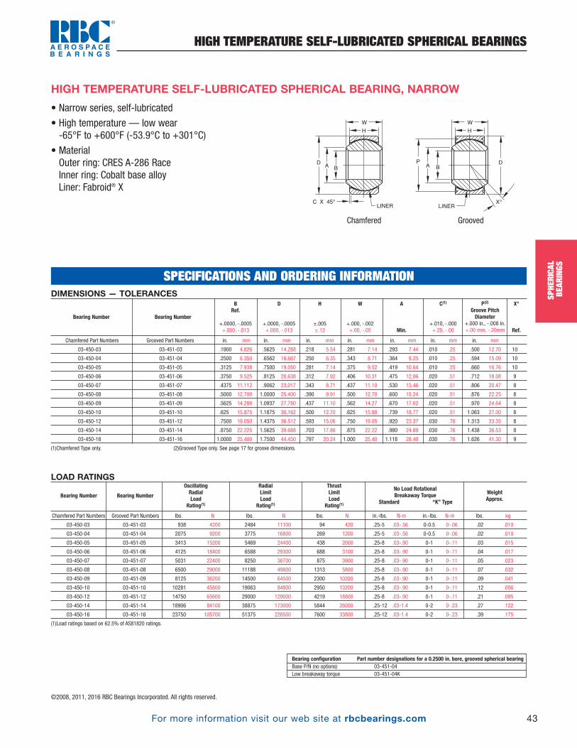
For more information visit our web site at rbcbearings.com
HIGH TEMPERATURE SELF-LUBRICATED SPHERICAL BEARINGS
43
SPHE
RICA
LBE
ARIN
GS
©2008, 2011, 2016 RBC Bearings Incorporated. All rights reserved.
LOAD RATINGS
Chamfered Part Numbers Grooved Part Numbers lbs. N lbs. N lbs. N in.-lbs. N-m in.-lbs. N-m lbs. kg
03-450-03 03-451-03 938 4200 2484 11100 94 420 .25-5 .03-.56 0-0.5 0-.06 .02 .010
03-450-04 03-451-04 2075 9200 3775 16800 269 1200 .25-5 .03-.56 0-0.5 0-.06 .02 .010
03-450-05 03-451-05 3413 15200 5469 24400 438 2000 .25-8 .03-.90 0-1 0-.11 .03 .015
03-450-06 03-451-06 4125 18400 6588 29300 688 3100 .25-8 .03-.90 0-1 0-.11 .04 .017
03-450-07 03-451-07 5031 22400 8250 36700 875 3900 .25-8 .03-.90 0-1 0-.11 .05 .023
03-450-08 03-451-08 6500 29000 11188 49800 1313 5800 .25-8 .03-.90 0-1 0-.11 .07 .032
03-450-09 03-451-09 8125 36200 14500 64500 2300 10200 .25-8 .03-.90 0-1 0-.11 .09 .041
03-450-10 03-451-10 10281 45800 19063 84800 2950 13200 .25-8 .03-.90 0-1 0-.11 .12 .056
03-450-12 03-451-12 14750 65600 29000 129000 4219 18800 .25-8 .03-.90 0-1 0-.11 .21 .095
03-450-14 03-451-14 18906 84100 38875 173000 5844 26000 .25-12 .03-1.4 0-2 0-.23 .27 .122
03-450-16 03-451-16 23750 105700 51375 228500 7600 33800 .25-12 .03-1.4 0-2 0-.23 .39 .175
(1)Load ratings based on 62.5% of AS81820 ratings.
ThrustLimitLoad
Rating(1)
WeightApprox.
No Load RotationalBreakaway Torque
Standard “K” Type
RadialLimitLoad
Rating(1)
OscillatingRadialLoad
Rating(1)Bearing Number Bearing Number
Bearing configuration Part number designations for a 0.2500 in. bore, grooved spherical bearingBase P/N (no options) 03-451-04Low breakaway torque 03-451-04K
• Narrow series, self-lubricated
• High temperature — low wear-65°F to +600°F (-53.9°C to +301°C)
• MaterialOuter ring: CRES A-286 RaceInner ring: Cobalt base alloy Liner: Fabroid® X
HIGH TEMPERATURE SELF-LUBRICATED SPHERICAL BEARING, NARROW
DIMENSIONS — TOLERANCES
Chamfered Part Numbers Grooved Part Numbers in. mm in. mm in. mm in. mm in. mm in. mm in. mm
03-450-03 03-451-03 .1900 4.826 .5625 14.288 .218 5.54 .281 7.14 .293 7.44 .010 .25 .500 12.70 10
03-450-04 03-451-04 .2500 6.350 .6562 16.667 .250 6.35 .343 8.71 .364 9.25 .010 .25 .594 15.09 10
03-450-05 03-451-05 .3125 7.938 .7500 19.050 .281 7.14 .375 9.52 .419 10.64 .010 .25 .660 16.76 10
03-450-06 03-451-06 .3750 9.525 .8125 20.638 .312 7.92 .406 10.31 .475 12.06 .020 .51 .712 18.08 9
03-450-07 03-451-07 .4375 11.112 .9062 23.017 .343 8.71 .437 11.10 .530 13.46 .020 .51 .806 20.47 8
03-450-08 03-451-08 .5000 12.700 1.0000 25.400 .390 9.91 .500 12.70 .600 15.24 .020 .51 .876 22.25 8
03-450-09 03-451-09 .5625 14.288 1.0937 27.780 .437 11.10 .562 14.27 .670 17.02 .020 .51 .970 24.64 8
03-450-10 03-451-10 .625 15.875 1.1875 30.162 .500 12.70 .625 15.88 .739 18.77 .020 .51 1.063 27.00 8
03-450-12 03-451-12 .7500 19.050 1.4375 36.512 .593 15.06 .750 19.05 .920 23.37 .030 .76 1.313 33.35 8
03-450-14 03-451-14 .8750 22.225 1.5625 39.688 .703 17.86 .875 22.22 .980 24.89 .030 .76 1.438 36.53 8
03-450-16 03-451-16 1.0000 25.400 1.7500 44.450 .797 20.24 1.000 25.40 1.118 28.40 .030 .76 1.626 41.30 9
(1)Chamfered Type only. (2)Grooved Type only. See page 17 for groove dimensions.
X°
Ref.
P(2)
Groove PitchDiameter
+.000 in., -.008 in.+.00 mm, -.20mm
C(1)
+.010, -.000 +.25, -.00
A
Min.
W
+.000, -.002 +.00, -.05
H
±.005 ±.13
D
+.0000, -.0005 +.000, -.013
BRef.
+.0000, -.0005 +.000, -.013
Bearing Number Bearing Number
SPECIFICATIONS AND ORDERING INFORMATION
A B
LINER
W
H
C X 45° X°
PDA
B
LINER
W
H
D
Chamfered Grooved
SPHE
RICA
LBE
ARIN
GSPB_018_048_8-30-16_Pln_018_050.qxd 8/30/16 11:00 AM Page 43
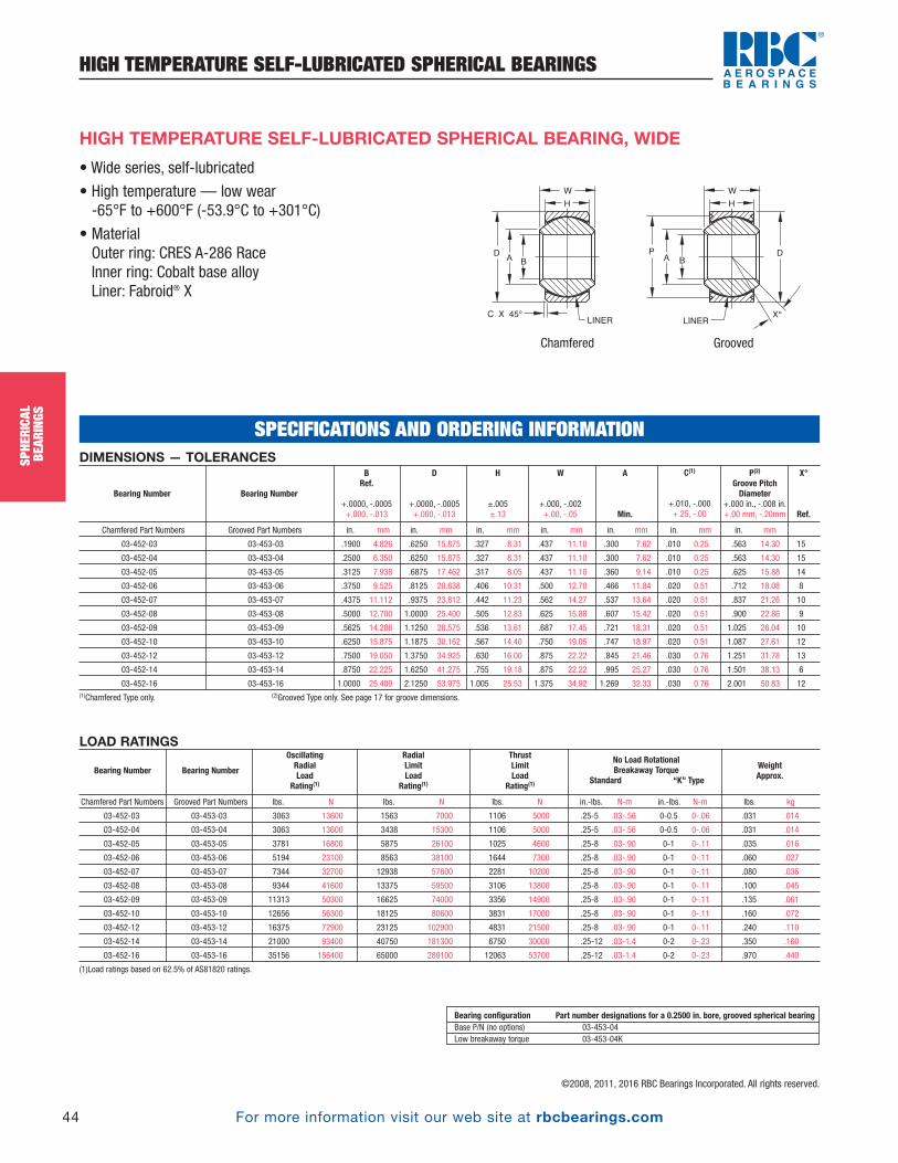
For more information visit our web site at rbcbearings.com
HIGH TEMPERATURE SELF-LUBRICATED SPHERICAL BEARINGS
44
SPHE
RICA
LBE
ARIN
GS
©2008, 2011, 2016 RBC Bearings Incorporated. All rights reserved.
SPHE
RICA
LBE
ARIN
GS
A B
LINER
G
W
H
C X 45° X°
PDA
B
LINER
W
H
D
Chamfered Grooved
• Wide series, self-lubricated
• High temperature — low wear-65°F to +600°F (-53.9°C to +301°C)
• MaterialOuter ring: CRES A-286 RaceInner ring: Cobalt base alloy Liner: Fabroid® X
HIGH TEMPERATURE SELF-LUBRICATED SPHERICAL BEARING, WIDE
DIMENSIONS — TOLERANCES
Chamfered Part Numbers Grooved Part Numbers in. mm in. mm in. mm in. mm in. mm in. mm in. mm
03-452-03 03-453-03 .1900 4.826 .6250 15.875 .327 8.31 .437 11.10 .300 7.62 .010 0.25 .563 14.30 15
03-452-04 03-453-04 .2500 6.350 .6250 15.875 .327 8.31 .437 11.10 .300 7.62 .010 0.25 .563 14.30 15
03-452-05 03-453-05 .3125 7.938 .6875 17.462 .317 8.05 .437 11.10 .360 9.14 .010 0.25 .625 15.88 14
03-452-06 03-453-06 .3750 9.525 .8125 20.638 .406 10.31 .500 12.70 .466 11.84 .020 0.51 .712 18.08 8
03-452-07 03-453-07 .4375 11.112 .9375 23.812 .442 11.23 .562 14.27 .537 13.64 .020 0.51 .837 21.26 10
03-452-08 03-453-08 .5000 12.700 1.0000 25.400 .505 12.83 .625 15.88 .607 15.42 .020 0.51 .900 22.86 9
03-452-09 03-453-09 .5625 14.288 1.1250 28.575 .536 13.61 .687 17.45 .721 18.31 .020 0.51 1.025 26.04 10
03-452-10 03-453-10 .6250 15.875 1.1875 30.162 .567 14.40 .750 19.05 .747 18.97 .020 0.51 1.087 27.61 12
03-452-12 03-453-12 .7500 19.050 1.3750 34.925 .630 16.00 .875 22.22 .845 21.46 .030 0.76 1.251 31.78 13
03-452-14 03-453-14 .8750 22.225 1.6250 41.275 .755 19.18 .875 22.22 .995 25.27 .030 0.76 1.501 38.13 6
03-452-16 03-453-16 1.0000 25.400 2.1250 53.975 1.005 25.53 1.375 34.92 1.269 32.33 .030 0.76 2.001 50.83 12(1)Chamfered Type only. (2)Grooved Type only. See page 17 for groove dimensions.
X°
Ref.
P(2)
Groove PitchDiameter
+.000 in., -.008 in.+.00 mm, -.20mm
C(1)
+.010, -.000 +.25, -.00
A
Min.
W
+.000, -.002 +.00, -.05
H
±.005 ±.13
D
+.0000, -.0005 +.000, -.013
BRef.
+.0000, -.0005 +.000, -.013
Bearing Number Bearing Number
LOAD RATINGS
Chamfered Part Numbers Grooved Part Numbers lbs. N lbs. N lbs. N in.-lbs. N-m in.-lbs. N-m lbs. kg
03-452-03 03-453-03 3063 13600 1563 7000 1106 5000 .25-5 .03-.56 0-0.5 0-.06 .031 .014
03-452-04 03-453-04 3063 13600 3438 15300 1106 5000 .25-5 .03-.56 0-0.5 0-.06 .031 .014
03-452-05 03-453-05 3781 16800 5875 26100 1025 4600 .25-8 .03-.90 0-1 0-.11 .035 .016
03-452-06 03-453-06 5194 23100 8563 38100 1644 7300 .25-8 .03-.90 0-1 0-.11 .060 .027
03-452-07 03-453-07 7344 32700 12938 57600 2281 10200 .25-8 .03-.90 0-1 0-.11 .080 .036
03-452-08 03-453-08 9344 41600 13375 59500 3106 13800 .25-8 .03-.90 0-1 0-.11 .100 .045
03-452-09 03-453-09 11313 50300 16625 74000 3356 14900 .25-8 .03-.90 0-1 0-.11 .135 .061
03-452-10 03-453-10 12656 56300 18125 80600 3831 17000 .25-8 .03-.90 0-1 0-.11 .160 .072
03-452-12 03-453-12 16375 72900 23125 102900 4831 21500 .25-8 .03-.90 0-1 0-.11 .240 .110
03-452-14 03-453-14 21000 93400 40750 181300 6750 30000 .25-12 .03-1.4 0-2 0-.23 .350 .160
03-452-16 03-453-16 35156 156400 65000 289100 12063 53700 .25-12 .03-1.4 0-2 0-.23 .970 .440
(1)Load ratings based on 62.5% of AS81820 ratings.
ThrustLimitLoad
Rating(1)
WeightApprox.
No Load RotationalBreakaway Torque
Standard “K” Type
RadialLimitLoad
Rating(1)
OscillatingRadialLoad
Rating(1)Bearing Number Bearing Number
Bearing configuration Part number designations for a 0.2500 in. bore, grooved spherical bearingBase P/N (no options) 03-453-04Low breakaway torque 03-453-04K
SPECIFICATIONS AND ORDERING INFORMATION
PB_018_048_8-30-16_Pln_018_050.qxd 8/30/16 11:00 AM Page 44
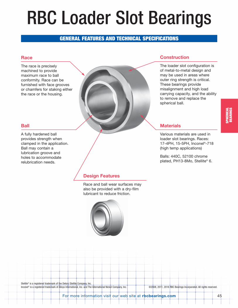
Stellite® is a registered trademark of the Deloro Stellite Company, Inc.Inconel® is a registered trademark of Alloys International, Inc. and The International Nickel Company, Inc.
SPHE
RICA
LBE
ARIN
GS
RBC Loader Slot BearingsGENERAL FEATURES AND TECHNICAL SPECIFICATIONS
Race
The race is preciselymachined to providemaximum race to ballconformity. Race can befurnished with face groovesor chamfers for staking eitherthe race or the housing.
Materials
Various materials are used inloader slot bearings. Races: 17-4PH, 15-5PH, Inconel®-718(high temp applications)
Balls: 440C, 52100 chromeplated, PH13-8Mo, Stellite® 6.
Construction
The loader slot configuration isof metal-to-metal design andmay be used in areas whereouter ring strength is critical.These bearings providemisalignment and high loadcarrying capacity, and the abilityto remove and replace thespherical ball.
Design Features
Race and ball wear surfaces mayalso be provided with a dry-filmlubricant to reduce friction.
Ball
A fully hardened ballprovides strength whenclamped in the application.Ball may contain alubrication groove andholes to accommodate relubrication needs.
©2008, 2011, 2016 RBC Bearings Incorporated. All rights reserved.
SPHE
RICA
LBE
ARIN
GS
For more information visit our web site at rbcbearings.com 45
SPHE
RICA
LBE
ARIN
GS
PB_018_048_8-30-16_Pln_018_050.qxd 8/30/16 11:00 AM Page 45

For more information visit our web site at rbcbearings.com
SINGLE V-GROOVE BEARINGS
46
SPHE
RICA
LBE
ARIN
GS
SPHE
RICA
LBE
ARIN
GS
• MaterialBall: Cobalt Alloy per AMS 538737 HRC minimumRace: 15-5PH CRES per AMS 5659Cond H-1050
• Surface TreatmentBall O.D.: Solid film lubricantRace Spherical I.D.: Nitrided
W
H
Ø B Ø C{ Ø A }
BALL (ØS)
Ø D
X°
DIMENSIONS — TOLERANCES
in. mm in. mm in. mm in. mm in. mm in. mm in. mm
03 0.1900 4.826 0.5625 14.288 0.218 5.54 0.281 7.14 0.582 14.78 0.293 7.44 0.4060 10.312 10
04 0.2500 6.350 0.6562 16.667 0.250 6.35 0.343 8.71 0.676 17.17 0.405 10.29 0.5300 13.462 12
05 0.3125 7.938 0.7500 19.050 0.281 7.14 0.375 9.53 0.770 19.56 0.420 10.67 0.5625 14.288 11
06 0.3750 9.525 0.8125 20.638 0.312 7.92 0.406 10.31 0.852 21.64 0.476 12.09 0.6250 15.875 10
07 0.4375 11.113 0.9062 23.017 0.343 8.71 0.437 11.10 0.946 24.03 0.530 13.46 0.6865 17.437 9
08 0.5000 12.700 1.0000 25.400 0.390 9.91 0.500 12.70 1.080 27.43 0.641 16.28 0.8125 20.638 9
09 0.5625 14.288 1.0937 27.780 0.437 11.10 0.562 14.27 1.174 29.82 0.671 17.04 0.8750 22.225 9
10 0.6250 15.875 1.1875 30.163 0.500 12.70 0.625 15.88 1.267 32.18 0.740 18.80 0.9680 24.587 9
12 0.7500 19.050 1.4375 36.513 0.593 15.06 0.750 19.05 1.517 38.53 0.921 23.39 1.1870 30.150 9
14 0.8750 22.225 1.5625 39.688 0.703 17.86 0.875 22.23 1.642 41.71 0.978 24.84 1.3120 33.325 9
16 1.0000 25.400 1.7500 44.450 0.797 20.24 1.000 25.40 1.830 46.48 1.119 28.42 1.5000 38.100 9
.002 inch max internal clearance (contact RBC engineering for reduced clearance design)
LHSSFGTMxx
Dash No.
S
Ref. Ref.
X°
Ref.
A
Ø Ref. Ø Ref.
C
+.002, -.002 +.051, -.051
W
+.000, -.002 +.000, -.051
H
+.003, -.003 +0.76, -.0.76
D
+0.0000, -.0005 +0.000, -.013
B
+.0000, -.0005 +.000, -.013
LOAD RATINGS
lbf. N lbf. N
03 2,256 8257 995 3641
04 3,904 14289 1,160 4245
05 7,136 26119 1,320 4831
06 11,408 41756 1,630 5966
07 16,640 60906 1,810 6625
08 19,040 69691 2,000 7320
09 21,512 78739 2,550 9333
10 23,256 85122 2,770 10138
12 28,168 103101 3,350 12261
14 32,400 118592 3,640 13323
16 37,264 136395 4,080 14933
Static Limit loads are approximate based on pin deflection and slot orientation
Static Limit Loads 1/
Radial Axial
LHSSFGTMxx
Dash No.
SPECIFICATIONS AND ORDERING INFORMATION
©2008, 2011, 2016 RBC Bearings Incorporated. All rights reserved.
CORROSION RESISTANT SINGLE V-GROOVE BEARING
PB_018_048_8-30-16_Pln_018_050.qxd 8/30/16 11:00 AM Page 46
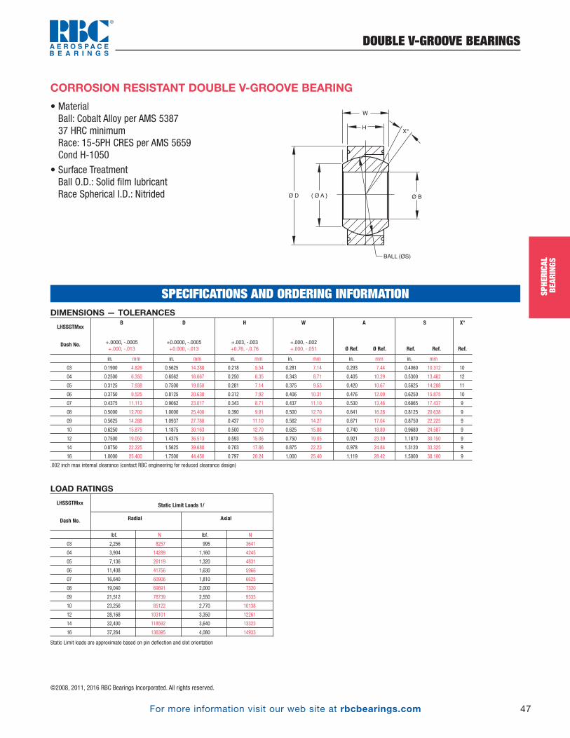
For more information visit our web site at rbcbearings.com
DOUBLE V-GROOVE BEARINGS
47
SPHE
RICA
LBE
ARIN
GS
©2008, 2011, 2016 RBC Bearings Incorporated. All rights reserved.
• MaterialBall: Cobalt Alloy per AMS 538737 HRC minimumRace: 15-5PH CRES per AMS 5659Cond H-1050
• Surface TreatmentBall O.D.: Solid film lubricantRace Spherical I.D.: Nitrided
CORROSION RESISTANT DOUBLE V-GROOVE BEARING
W
H
Ø B{ Ø A }
BALL (ØS)
Ø D
X°
DIMENSIONS — TOLERANCES
in. mm in. mm in. mm in. mm in. mm in. mm
03 0.1900 4.826 0.5625 14.288 0.218 5.54 0.281 7.14 0.293 7.44 0.4060 10.312 10
04 0.2500 6.350 0.6562 16.667 0.250 6.35 0.343 8.71 0.405 10.29 0.5300 13.462 12
05 0.3125 7.938 0.7500 19.050 0.281 7.14 0.375 9.53 0.420 10.67 0.5625 14.288 11
06 0.3750 9.525 0.8125 20.638 0.312 7.92 0.406 10.31 0.476 12.09 0.6250 15.875 10
07 0.4375 11.113 0.9062 23.017 0.343 8.71 0.437 11.10 0.530 13.46 0.6865 17.437 9
08 0.5000 12.700 1.0000 25.400 0.390 9.91 0.500 12.70 0.641 16.28 0.8125 20.638 9
09 0.5625 14.288 1.0937 27.780 0.437 11.10 0.562 14.27 0.671 17.04 0.8750 22.225 9
10 0.6250 15.875 1.1875 30.163 0.500 12.70 0.625 15.88 0.740 18.80 0.9680 24.587 9
12 0.7500 19.050 1.4375 36.513 0.593 15.06 0.750 19.05 0.921 23.39 1.1870 30.150 9
14 0.8750 22.225 1.5625 39.688 0.703 17.86 0.875 22.23 0.978 24.84 1.3120 33.325 9
16 1.0000 25.400 1.7500 44.450 0.797 20.24 1.000 25.40 1.119 28.42 1.5000 38.100 9
.002 inch max internal clearance (contact RBC engineering for reduced clearance design)
LHSSGTMxx
Dash No.
S
Ref. Ref.
X°
Ref.
A
Ø Ref. Ø Ref.
W
+.000, -.002 +.000, -.051
H
+.003, -.003 +0.76, -.0.76
D
+0.0000, -.0005 +0.000, -.013
B
+.0000, -.0005 +.000, -.013
SPECIFICATIONS AND ORDERING INFORMATIONSPHE
RICA
LBE
ARIN
GS
LOAD RATINGS
lbf. N lbf. N
03 2,256 8257 995 3641
04 3,904 14289 1,160 4245
05 7,136 26119 1,320 4831
06 11,408 41756 1,630 5966
07 16,640 60906 1,810 6625
08 19,040 69691 2,000 7320
09 21,512 78739 2,550 9333
10 23,256 85122 2,770 10138
12 28,168 103101 3,350 12261
14 32,400 118592 3,640 13323
16 37,264 136395 4,080 14933
Static Limit loads are approximate based on pin deflection and slot orientation
Static Limit Loads 1/
Radial Axial
LHSSGTMxx
Dash No.
PB_018_048_8-30-16_Pln_018_050.qxd 8/30/16 11:00 AM Page 47

RBC Split Ball BearingsGENERAL FEATURES AND TECHNICAL SPECIFICATIONS
Race
The race is preciselymachined to providemaximum ball to raceconformity like a loader slot,but without the loss of loadcarrying area caused bymachining the loader slot.The race can be furnishedwith face grooves, chamfers,flanges, or threads forretention in the housing. Therace can be manufacturedfrom a variety of alloys suchas steel, aluminum, ortitanium. Lubricant can begrease, dry-film, or PTFEliner.
Materials
Various materials are use.Races: 17-4PH, 15-5PH,Inconel® 718, aluminum(requires PTFE liner or hardcoat), titanium (requires PTFEliner or hard coat).
Balls: Copper alloys, titanium,aluminum, 440C, PH13-8Mo,15-5PH, 17-4PH, cobalt alloys.
Construction
The split ball is replaceable when it wears out. In unclampedapplications, most wear islimited to the ball bore, allowingthe race to be reused in certainapplications.
Design
Usually grease lubricated, steel race, copperalloy ball. Titanium hard coated race, greaselube, or copper ball also possible. All titaniumcomponent construction is possible. Self-lubricating PTFE liners are also an option.
Ball
The ball is split and designed around a “zero gap.”The ball is typically a softer material, such ascopper alloy or bronze, for grease lubricatedapplications. For PTFE lined, the ball may behardened or have a hard coating applied to thesphere. Split ball bearings are best used inunclamped applications, where the pin/bolt is free to rotate in the ball bore. Clamped bore applications require specialconsiderations/designs.
Inconel® is a registered trademark of Alloys International, Inc. and The international Nickel Company, Inc. ©2008, 2011, 2016 RBC Bearings Incorporated. All rights reserved.
48 For more information visit our web site at rbcbearings.com
SPHE
RICA
LBE
ARIN
GS
PB_018_048_8-30-16_Pln_018_050.qxd 8/30/16 11:00 AM Page 48
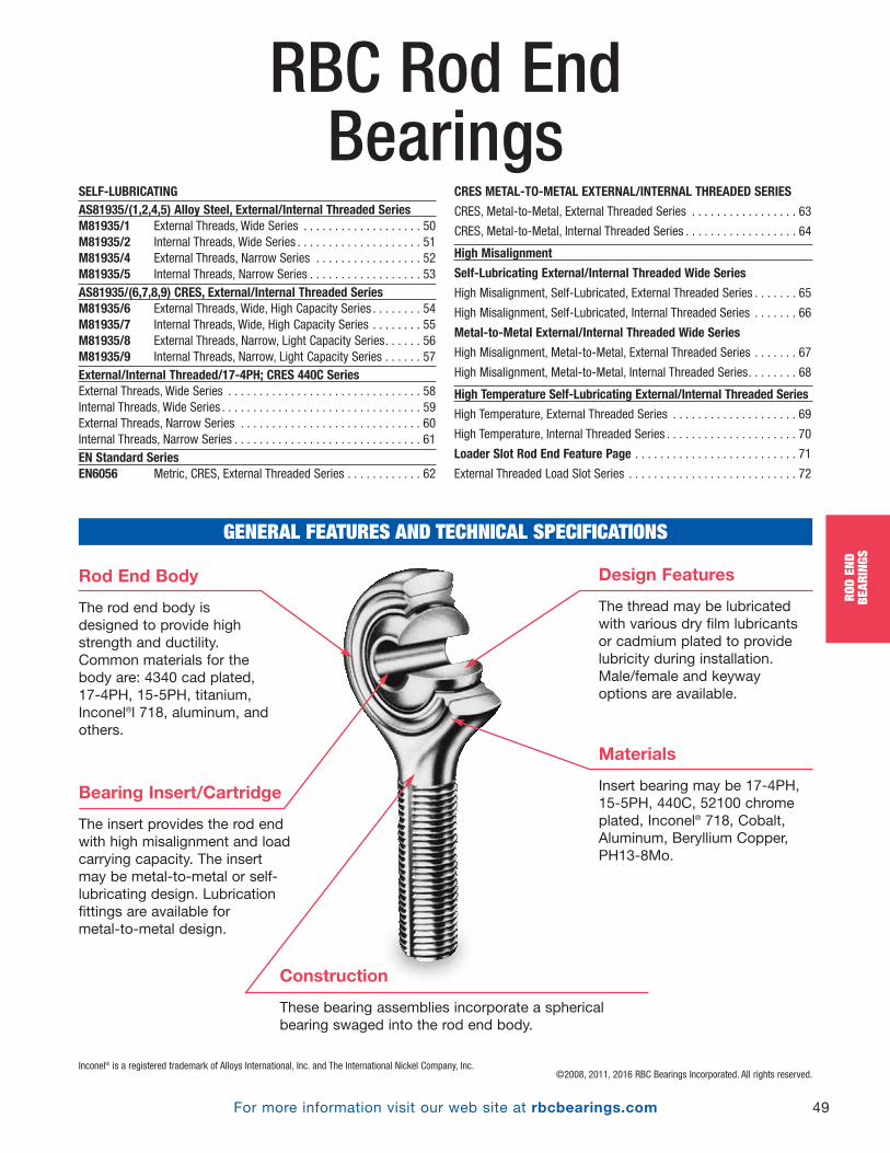
©2008, 2011, 2016 RBC Bearings Incorporated. All rights reserved.
RBC Rod End Bearings
For more information visit our web site at rbcbearings.com 49
ROD
END
BEAR
INGS
GENERAL FEATURES AND TECHNICAL SPECIFICATIONS
Rod End Body
The rod end body isdesigned to provide highstrength and ductility.Common materials for thebody are: 4340 cad plated,17-4PH, 15-5PH, titanium,Inconel®l 718, aluminum, andothers.
Materials
Insert bearing may be 17-4PH,15-5PH, 440C, 52100 chromeplated, Inconel® 718, Cobalt,Aluminum, Beryllium Copper,PH13-8Mo.
Design Features
The thread may be lubricatedwith various dry film lubricantsor cadmium plated to providelubricity during installation.Male/female and keywayoptions are available.
Construction
These bearing assemblies incorporate a sphericalbearing swaged into the rod end body.
Bearing Insert/Cartridge
The insert provides the rod endwith high misalignment and loadcarrying capacity. The insert may be metal-to-metal or self-lubricating design. Lubricationfittings are available for metal-to-metal design.
Inconel® is a registered trademark of Alloys International, Inc. and The International Nickel Company, Inc.
SELF-LUBRICATINGAS81935/(1,2,4,5) Alloy Steel, External/Internal Threaded SeriesM81935/1 External Threads, Wide Series . . . . . . . . . . . . . . . . . . . 50M81935/2 Internal Threads, Wide Series . . . . . . . . . . . . . . . . . . . . 51M81935/4 External Threads, Narrow Series . . . . . . . . . . . . . . . . . 52M81935/5 Internal Threads, Narrow Series . . . . . . . . . . . . . . . . . . 53AS81935/(6,7,8,9) CRES, External/Internal Threaded SeriesM81935/6 External Threads, Wide, High Capacity Series . . . . . . . . 54M81935/7 Internal Threads, Wide, High Capacity Series . . . . . . . . 55M81935/8 External Threads, Narrow, Light Capacity Series. . . . . . 56M81935/9 Internal Threads, Narrow, Light Capacity Series . . . . . . 57External/Internal Threaded/17-4PH; CRES 440C SeriesExternal Threads, Wide Series . . . . . . . . . . . . . . . . . . . . . . . . . . . . . . . 58Internal Threads, Wide Series . . . . . . . . . . . . . . . . . . . . . . . . . . . . . . . . 59External Threads, Narrow Series . . . . . . . . . . . . . . . . . . . . . . . . . . . . . 60Internal Threads, Narrow Series . . . . . . . . . . . . . . . . . . . . . . . . . . . . . . 61EN Standard SeriesEN6056 Metric, CRES, External Threaded Series . . . . . . . . . . . . 62
CRES METAL-TO-METAL EXTERNAL/INTERNAL THREADED SERIES
CRES, Metal-to-Metal, External Threaded Series . . . . . . . . . . . . . . . . . 63
CRES, Metal-to-Metal, Internal Threaded Series . . . . . . . . . . . . . . . . . . 64
High Misalignment
Self-Lubricating External/Internal Threaded Wide Series
High Misalignment, Self-Lubricated, External Threaded Series . . . . . . . 65
High Misalignment, Self-Lubricated, Internal Threaded Series . . . . . . . 66
Metal-to-Metal External/Internal Threaded Wide Series
High Misalignment, Metal-to-Metal, External Threaded Series . . . . . . . 67
High Misalignment, Metal-to-Metal, Internal Threaded Series. . . . . . . . 68
High Temperature Self-Lubricating External/Internal Threaded Series
High Temperature, External Threaded Series . . . . . . . . . . . . . . . . . . . . 69
High Temperature, Internal Threaded Series . . . . . . . . . . . . . . . . . . . . . 70
Loader Slot Rod End Feature Page . . . . . . . . . . . . . . . . . . . . . . . . . . 71
External Threaded Load Slot Series . . . . . . . . . . . . . . . . . . . . . . . . . . . 72
PB_049_072_8-29-16_Pln_051_078.qxd 8/30/16 11:04 AM Page 49
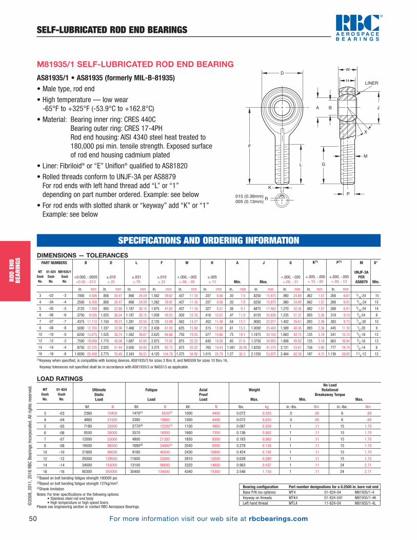
©2008, 2011, 2016 RBC Bearings Incorporated. All rights reserved.
For more information visit our web site at rbcbearings.com
SELF-LUBRICATED ROD END BEARINGS
50
ROD
END
BEAR
INGS
AS81935/1 • AS81935 (formerly MIL-B-81935)• Male type, rod end
• High temperature — low wear -65°F to +325°F (-53.9°C to +162.8°C)
• Material: Bearing inner ring: CRES 440CBearing outer ring: CRES 17-4PHRod end housing: AISI 4340 steel heat treated to 180,000 psi min. tensile strength. Exposed surface of rod end housing cadmium plated
• Liner: Fibriloid® or “E” Uniflon® qualified to AS81820
• Rolled threads conform to UNJF-3A per AS8879For rod ends with left hand thread add “L” or “1” depending on part number ordered. Example: see below
• For rod ends with slotted shank or “keyway” add “K” or “1” Example: see below
F
015 (0.38mm)
005 (0.13mm)
L G
P
M
K
R
A B J
LINER
X
DW
H
M81935/1 SELF-LUBRICATED ROD END BEARING
DIMENSIONS — TOLERANCES
in. mm in. mm in. mm in. mm in. mm in. mm in. mm in. mm in. mm in. mm in. mm
.1900 4.826 .806 20.47 .968 24.59 1.562 39.67 .437 11.10 .337 8.56 .30 7.6 .6250 15.875 .980 24.89 .062 1.57 .268 6.81 5/16-24 15
.2500 6.350 .806 20.47 .968 24.59 1.562 39.67 .437 11.10 .337 8.56 .30 7.6 .6250 15.875 .980 24.89 .062 1.57 .268 6.81 5/16-24 15
.3125 7.938 .900 22.86 1.187 30.15 1.875 47.62 .437 11.10 .327 8.31 .36 9.1 .6875 17.462 1.270 32.26 .062 1.57 .268 6.81 5/16-24 14
.3750 9.525 1.025 26.04 1.187 30.15 1.938 49.23 .500 12.70 .416 10.57 .47 11.9 .8125 20.638 1.235 31.37 .093 2.36 .319 8.10 3/8-24 8
.4375 11.112 1.150 29.21 1.281 32.54 2.125 53.98 .562 14.27 .452 11.48 .54 13.7 .9062 23.017 1.402 35.61 .093 2.36 .383 9.73 7/16-20 10
.5000 12.700 1.337 33.96 1.468 37.29 2.438 61.93 .625 15.88 .515 13.08 .61 15.5 1.0000 25.400 1.589 40.36 .093 2.36 .445 11.30 1/2-20 9
.6250 15.875 1.525 38.74 1.562 39.67 2.625 66.68 .750 19.05 .577 14.66 .75 19.1 1.1875 30.162 1.683 42.75 .125 3.18 .541 13.74 5/8-18 12
.7500 19.050 1.775 45.08 1.687 42.85 2.875 73.02 .875 22.22 .640 16.26 .85 21.6 1.3750 34.925 1.808 45.92 .125 3.18 .663 16.84 3/4-16 13
.8750 22.225 2.025 51.44 2.000 50.80 3.375 85.72 .875 22.22 .765 19.43 1.061 26.95 1.6250 41.275 2.121 53.87 .156 3.96 .777 19.74 7/8-14 6
1.0000 25.400 2.775 70.48 2.343 59.51 4.125 104.78 1.375 34.92 1.015 25.78 1.27 32.3 2.1250 53.975 2.464 62.59 .187 4.75 1.136 28.85 11/4-12 12(1)Keyway when specified, is compatible with locking devices, AS81935/3 for sizes 3 thru 8, and NAS559 for sizes 10 thru 16.
Keyway tolerances not specified shall be in accordance with AS81935/3 or NAS513 as applicable.
P(1)
+.000, -.005 +.00, -.13
K(1)
+.005, -.000 +.13, -.00
G
+.000, -.020 +.00, -.51
J
Max.
X°
Min.
M
UNJF-3APER
AS8879
A
Min.
H
±.005 ±.13
W
+.000, -.002 +.00, -.05
F
±.010 ±.25
L
±.031 ±.79
D
±.010±.25
B
+0.000, -.0005 +0.00, -.013
PART NUMBERS
MT 01-824 M81935/1Dash Dash DashNo. No. No.
3 -03 -3
4 -04 -4
5 -05 -5
6 -06 -6
7 -07 -7
8 -08 -8
10 -10 -0
12 -12 -2
14 -14 -4
16 -16 -6
MT 01-824Dash DashNo. No.
3 -03
4 -04
5 -05
6 -06
7 -07
8 -08
10 -10
12 -12
14 -14
16 -16
Bearing configuration Part number designations for a 0.2500 in. bore rod endBase P/N (no options) MT4 01-824-04 M81935/1-4Keyway on threads MTK4 01-824-041 M81935/1-4KLeft hand thread MTL4 11-824-04 M81935/1-4L
SPECIFICATIONS AND ORDERING INFORMATION
LOAD RATINGS
lbf. N lbf. N lbf. N lbs. kg in.-lbs. Nm in.-lbs. Nm
2360 10400 1470(1) 6550(2) 1000 4400 0.072 0.033 .5 .06 6 .68
4860 21600 2380 10600 1000 4400 0.072 0.033 .5 .06 6 .68
7180 32000 2770(3) 12200(3) 1100 4900 0.087 0.039 1 .11 15 1.70
8550 38000 3570 16000 1660 7350 0.136 0.062 1 .11 15 1.70
12000 53000 4800 21200 1850 8300 0.183 0.083 1 .11 15 1.70
19500 86500 7680(3) 34000(3) 2040 9000 0.278 0.126 1 .11 15 1.70
21900 98000 9180 40500 2430 10800 0.424 0.192 1 .11 15 1.70
29300 129000 11600 52000 2810 12500 0.639 0.290 1 .11 15 1.70
34500 153000 13100 58500 3320 14600 0.963 0.437 1 .11 24 2.71
80300 355000 30400 134000 4340 19300 2.546 1.150 1 .11 24 2.71(1)Based on bolt bending fatigue strength 180000 psi(2)Based on bolt bending fatigue strength 127kg/mm2. (3)Shank limitation Notes: For liner specifications or the following options:
• Stainless steel rod end body• High temperature or high speed liners
Please see engineering section or contact RBC Aerospace Bearings.
UltimateStaticLoad
No LoadRotational
Breakaway TorqueMin. Max.
Weight
Max.
AxialProofLoad
Fatigue
Load
PB_049_072_8-29-16_Pln_051_078.qxd 8/30/16 11:04 AM Page 50

©2008, 2011, 2016 RBC Bearings Incorporated. All rights reserved.
For more information visit our web site at rbcbearings.com
SELF-LUBRICATED ROD END BEARINGS
51
ROD
END
BEAR
INGS
AS81935/2 • AS81935 (formerly MIL-B-81935)• Female type, rod end
• High temperature — low wear -65°F to +325°F (-53.9°C to +162.8°C)
• Material: Bearing inner ring: CRES 440CBearing outer ring: CRES 17-4PHRod end housing: AISI 4340 steel heat treated to 180,000 psi min. tensile strength. Exposed surface of rod end housing cadmium plated
• Liner: Fibriloid® or “E” Uniflon® qualified to AS81820
• Threads conform to UNJF-3B per AS8879. For left hand thread add “L” or “1” depending on part number orderedExample: see below
• For rod end with keyway in end of shank add “K” or “1” Example: see below
• For rod end with deep key slot on base add “W” Example: see below
D
F
T
S
M . 062
( 157mm)
INSPECTION
HOLE
R
A
W
H
LINER
B
X
L N
K
M
J
M81935/2 SELF-LUBRICATED ROD END BEARING
Notes:Ultimate Static Load — No fracture of rod ending housing or bearing will occur when the ultimate static load is applied in thebearing along the shank center line.
Axial Static Proof Load— Is the retention strength of the bearing within the eye of the rod end housing. No push out of thebearing cartridge will occur when the housing eye is supported and the axial proof load is applied to the face of insert bearinginner ring.
Fatigue Load— The rod end housing will withstand 50,000 cycles of full tension to 10% tension loading at speeds up to 2800 cpm. Load is applied in line with the rod end shank putting the eye in tension.
Bearing configuration Part number designations for a 0.2500 in. bore rod endBase P/N (no options) FT4 02-824-04 M81935/2-4Keyway on threads FTK4 02-824-041 M81935/2-4KLeft hand thread FTL4 12-824-04 M81935/2-4LDeep key slot on base FTW4 02-824-04W M81935/2-4W
LOAD RATINGS
lbf. N lbf. N lbf. N lbs. kg in.-lbs. Nm in.-lbs. Nm
2360 10400 1470(1) 6550(2) 1000 4400 0.080 0.030 .5 .06 6 .68
4860 21600 2380 10600 1000 4400 0.084 0.038 .5 .06 6 .68
7180 32000 3020 13400 1100 4900 0.102 0.046 1 .11 15 1.70
8550 38000 3570 16000 1660 7350 0.161 0.073 1 .11 15 1.70
12000 53000 4800 21200 1850 8300 0.212 0.096 1 .11 15 1.70
19500 86500 8260 36500 2040 9000 0.325 0.147 1 .11 15 1.70
21900 98000 9180 40500 2430 10800 0.481 0.218 1 .11 15 1.70
29300 130000 11600 51500 1810 12500 0.673 0.306 1 .11 15 1.70
34500 151000 13100 58000 1320 14800 0.959 0.436 1 .11 24 2.71
80300 357000 30400 135000 4340 19300 2.717 1.235 1 .11 24 2.71
(1)Based on bolt bending fatigue strength 180000 psi(2)Based on bolt bending fatigue strength 127kg/mm2. Check for availability.
UltimateStaticLoad
No LoadRotational
Breakaway TorqueMin. Max.
Weight
Max.
AxialProofLoad
Fatigue
Load
FT 02-824Dash DashNo. No.
3 -03
4 -04
5 -05
6 -06
7 -07
8 -08
10 -10
12 -12
14 -14
16 -16
DIMENSIONS — TOLERANCES
in. mm in. mm in. mm in. mm in. mm in. mm in. mm in. mm in. mm in. mm in. mm in. mm in. mm
.1900 4.826 .806 20.47 .750 19.05 1.375 34.92 .422 10.72 .437 11.10 .337 8.56 .30 7.6 .6250 15.875 .875 22.22 .500 12.70 .188 4.78 .437 11.10 5/16-24 15
.2500 6.350 .806 20.47 .750 19.05 1.469 37.31 .422 10.72 .437 11.10 .337 8.56 .30 7.6 .6250 15.875 .875 22.22 .500 12.70 .188 4.78 .437 11.10 5/16-24 15
.3125 7.938 .900 22.86 .875 22.22 1.625 41.28 .485 12.32 .437 11.10 .327 8.31 .36 9.1 .6875 17.462 1.000 25.40 .580 14.73 .250 6.35 .500 12.70 3/8-24 14
.3750 9.525 1.025 26.04 1.000 25.40 1.812 46.02 .547 13.89 .500 12.70 .416 10.57 .47 11.9 .8125 20.638 1.125 28.58 .660 16.76 .250 6.35 .562 14.27 3/18-24 8
.4375 11.112 1.150 29.21 1.125 28.58 2.000 50.80 .610 15.49 .562 14.27 .452 11.48 .54 13.7 .9062 23.017 1.250 31.75 .720 18.29 .250 6.35 .625 15.88 7/16-20 10
.5000 12.700 1.337 33.96 1.250 31.75 2.250 57.15 .735 18.67 .625 15.88 .515 13.08 .61 15.5 1.0000 25.400 1.375 34.92 .880 22.35 .250 6.35 .750 19.05 1/2-20 9
.6250 15.875 1.525 38.74 1.375 34.92 2.500 63.50 .860 21.84 .750 19.05 .577 14.66 .75 19.1 1.1875 30.162 1.500 38.10 1.020 25.91 .375 9.52 .875 22.22 5/8-18 12
.7500 19.050 1.775 45.09 1.625 41.28 2.875 73.03 .985 25.02 .875 22.23 .640 16.26 .85 21.6 1.3750 34.925 1.750 44.45 1.160 29.46 .375 9.53 1.000 25.40 3/4 - 16 13
.8750 22.225 2.025 51.44 1.875 47.63 3.375 85.73 1.110 28.19 .875 22.23 .765 19.43 1.00 25.4 1.6250 41.275 2.062 52.37 1.300 33.02 .500 12.70 1.125 28.58 7/8 - 14 6
1.0000 25.400 2.775 70.49 2.125 53.98 4.125 104.78 1.688 42.88 1.375 34.93 1.015 25.78 1.27 32.3 2.1250 53.975 2.312 58.72 2.020 51.31 .563 14.30 1.750 44.45 11/4 - 12 12(1)Completed thread. (2)Measured across corners or diameter.
S(2)
Ref.
N
Max.
J
Max.
A
Min.
K
±.010 ±.25
F
±.010 ±.25
R(1)
+.002, -.010 +.05, -.25
T
+.010, -.062 +.25, -1.57
X°
Min.
M
UNJF-3BPER
AS8879
H
±.005 ±.13
W
+.000, -.002 +.00, -.05
L(1)
Min.
D
±.010±.25
B
+0.000, -.0005 +0.00, -.013
PART NUMBERS
FT 02-824 M81935/2Dash Dash DashNo. No. No.
3 -03 -3
4 -04 -4
5 -05 -5
6 -06 -6
7 -07 -7
8 -08 -8
10 -10 -10
12 -12 -12
14 -14 -14
16 -16 -16
SPECIFICATIONS AND ORDERING INFORMATION
PB_049_072_8-29-16_Pln_051_078.qxd 8/30/16 11:04 AM Page 51
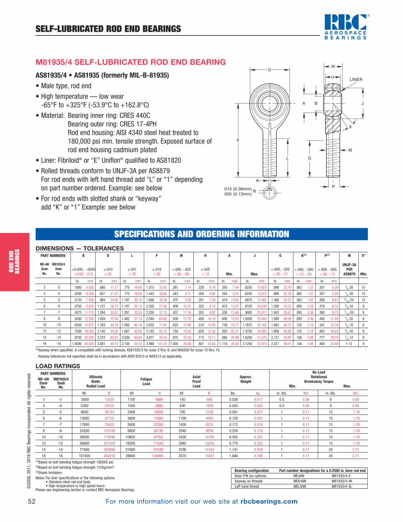
©2008, 2011, 2016 RBC Bearings Incorporated. All rights reserved.
For more information visit our web site at rbcbearings.com
SELF-LUBRICATED ROD END BEARINGS
52
ROD
END
BEAR
INGS
AS81935/4 • AS81935 (formerly MIL-B-81935)• Male type, rod end
• High temperature — low wear -65°F to +325°F (-53.9°C to +162.8°C)
• Material: Bearing inner ring: CRES 440CBearing outer ring: CRES 17-4PHRod end housing: AISI 4340 steel heat treated to 180,000 psi min. tensile strength. Exposed surface of rod end housing cadmium plated
• Liner: Fibriloid® or “E” Uniflon® qualified to AS81820
• Rolled threads conform to UNJF-3A per AS8879For rod ends with left hand thread add “L” or “1” depending on part number ordered. Example: see below
• For rod ends with slotted shank or “keyway” add “K” or “1” Example: see below
M81935/4 SELF-LUBRICATED ROD END BEARING
LOAD RATINGS
lbf. N lbf. N lbf. N lbs. kg in.-lbs. Nm in.-lbs. Nm
3 -3 3000 13320 1100 4884 150 666 0.038 0.017 0.5 0.06 6 0.68
4 -4 5300 23532 1500 6660 430 1909 0.045 0.020 0.5 0.06 6 0.68
5 -5 8600 38184 2400 10656 700 3108 0.081 0.037 1 0.11 15 1.70
6 -6 13000 57720 3600 15984 1100 4884 0.120 0.055 1 0.11 15 1.70
7 -7 17800 79032 5000 22200 1400 6216 0.172 0.078 1 0.11 15 1.70
8 -8 24200 107448 6800 30192 2040 9058 0.254 0.115 1 0.11 15 1.70
10 -10 38500 170940 10800 47952 2430 10789 0.455 0.207 1 0.11 15 1.70
12 -12 56600 251304 16000 71040 2940 13054 0.774 0.352 1 0.11 15 1.70
14 -14 77400 343656 21900 97236 3190 14164 1.141 0.519 1 0.11 24 2.71
16 -16 101400 450216 28600 126984 3570 15851 1.646 0.748 1 0.11 24 2.71(1)Based on bolt bending fatigue strength 180000 psi(2)Based on bolt bending fatigue strength 127kg/mm2. (3)Shank limitation Notes: For liner specifications or the following options:
• Stainless steel rod end body• High temperature or high speed liners
Please see engineering section or contact RBC Aerospace Bearings.
UltimateStatic
Radial Load
No LoadRotational
Breakaway TorqueMin. Max.
Approx.Weight
AxialProofLoad
FatigueLoad
PART NUMBERSME-ANDashNo.
M81935/4DashNo.
Bearing configuration Part number designations for a 0.2500 in. bore rod endBase P/N (no options) ME4AN M81935/4-4Keyway on threads MEK4AN M81935/4-4KLeft hand thread MEL4AN M81935/4-4L
SPECIFICATIONS AND ORDERING INFORMATION
F
015 (0.38mm)
005 (0.13mm)
L G
P
M
K
R
A B J
LINER
X
DW
H
DIMENSIONS — TOLERANCES
in. mm in. mm in. mm in. mm in. mm in. mm in. mm in. mm in. mm in. mm in. mm
.1900 4.826 .680 17.27 .775 19.69 1.315 33.40 .281 7.14 .228 5.79 .293 7.44 .6250 15.875 .896 22.76 .062 1.57 .207 5.26 1/4-28 10
.2500 6.350 .827 21.01 .775 19.69 1.443 36.65 .343 8.71 .260 6.60 .364 9.25 .6250 15.875 .896 22.76 .062 1.57 .207 5.26 1/4-28 10
.3125 7.938 .984 24.99 1.187 30.15 1.948 49.48 .375 9.53 .291 7.39 .419 10.64 .6875 17.462 1.308 33.22 .062 1.57 .268 6.81 5/16-24 10
.3750 9.525 1.131 28.73 1.187 30.15 2.030 51.56 .406 10.31 .322 8.18 .475 12.07 .8125 20.638 1.308 33.22 .093 2.36 .319 8.10 3/8-24 9
.4375 11.112 1.294 32.87 1.281 32.54 2.250 57.15 .437 11.10 .353 8.97 .530 13.46 .9062 23.017 1.402 35.61 .093 2.36 .383 9.73 7/16-20 8
.5000 12.700 1.459 37.06 1.462 37.13 2.544 64.62 .500 12.70 .400 10.16 .600 15.24 1.0000 25.400 1.589 40.36 .093 2.36 .445 11.30 1/2-20 8
.6250 15.875 1.763 44.78 1.582 40.18 2.832 71.93 .625 15.88 .510 12.95 .739 18.77 1.1875 30.162 1.683 42.75 .125 3.18 .541 13.74 5/8-18 8
.7500 19.050 2.140 54.36 1.687 42.85 3.193 81.10 .750 19.05 .603 15.32 .920 23.37 1.3750 34.925 1.808 45.92 .125 3.18 .663 16.84 3/4-16 8
.8750 22.225 2.372 60.25 2.000 50.80 3.677 93.40 .875 22.23 .713 18.11 .980 24.89 1.6250 41.275 2.121 53.87 .156 3.96 .777 19.74 7/8-14 8
1.0000 25.400 2.681 68.10 2.100 53.34 3.988 101.30 1.000 25.40 .807 20.50 1.118 28.40 2.1250 53.975 2.221 56.41 .156 3.96 .900 22.86 1-12 9(1)Keyway when specified, is compatible with locking devices, AS81935/3 for sizes 3 thru 8, and NAS559 for sizes 10 thru 16.
Keyway tolerances not specified shall be in accordance with AS81935/3 or NAS513 as applicable.
P(1)
+.000, -.005 +.00, -.13
K(1)
+.005, -.000 +.13, -.00
G
+.000, -.020 +.00, -.51
J
Max.
X°
Min.
M
UNJF-3APER
AS8879
A
Min.
H
±.005 ±.13
W
+.000, -.002 +.00, -.05
F
±.010 ±.25
L
±.031 ±.79
D
±.010±.25
B
+0.000, -.0005 +0.00, -.013
PART NUMBERS
ME-AN M81935/4Dash DashNo. No.
3 -3
4 -4
5 -5
6 -6
7 -7
8 -8
10 -10
12 -12
14 -14
16 -16
PB_049_072_8-29-16_Pln_051_078.qxd 8/30/16 11:04 AM Page 52
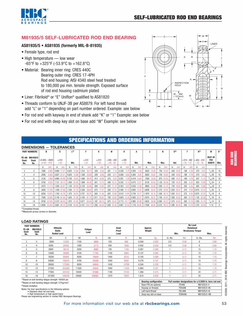
©2008, 2011, 2016 RBC Bearings Incorporated. All rights reserved.
For more information visit our web site at rbcbearings.com
SELF-LUBRICATED ROD END BEARINGS
53
ROD
END
BEAR
INGS
AS81935/5 • AS81935 (formerly MIL-B-81935)• Female type, rod end
• High temperature — low wear -65°F to +325°F (-53.9°C to +162.8°C)
• Material: Bearing inner ring: CRES 440CBearing outer ring: CRES 17-4PHRod end housing: AISI 4340 steel heat treated to 180,000 psi min. tensile strength. Exposed surface of rod end housing cadmium plated
• Liner: Fibriloid® or “E” Uniflon® qualified to AS81820
• Threads conform to UNJF-3B per AS8879. For left hand thread add “L” or “1” depending on part number ordered. Example: see below
• For rod end with keyway in end of shank add “K” or “1” Example: see below
• For rod end with deep key slot on base add “W” Example: see below
M81935/5 SELF-LUBRICATED ROD END BEARING
LOAD RATINGS
lbf. N lbf. N lbf. N lbs. kg in.-lbs. Nm in.-lbs. Nm
3 -3 3000 13320 1100 4884 150 666 0.044 0.020 0.5 0.06 6 0.68
4 -4 5500 24420 1300 5772 430 1909 0.052 0.024 0.5 0.06 6 0.68
5 -5 8900 39516 2000 8880 700 1108 0.087 0.040 1 0.11 15 1.70
6 -6 13400 59496 3100 11764 1100 4884 0.137 0.062 1 0.11 15 1.70
7 -7 18200 80808 4200 18648 1400 6216 0.193 0.088 1 0.11 15 1.70
8 -8 24600 109224 5700 25308 1040 9058 0.279 0.127 1 0.11 15 1.70
10 -10 39500 175380 9200 40848 1430 10789 0.504 0.229 1 0.11 15 1.70
12 -12 57200 253968 11500 59940 1940 11054 0.860 0.391 1 0.11 15 1.70
14 -14 77800 345432 18400 81696 1190 14164 1.266 0.575 1 0.11 24 2.71
16 -16 101000 448440 24000 106560 1570 15851 1.814 0.825 1 0.11 24 2.71(1)Based on bolt bending fatigue strength 180000 psi(2)Based on bolt bending fatigue strength 127kg/mm2. (3)Shank limitation Notes: For liner specifications or the following options:
• Stainless steel rod end body• High temperature or high speed liners
Please see engineering section or contact RBC Aerospace Bearings.
UltimateStatic
Radial Load
No LoadRotational
Breakaway TorqueMin. Max.
Approx.Weight
AxialProofLoad
FatigueLoad
PART NUMBERSFE-ANDashNo.
M81935/5DashNo.
Bearing configuration Part number designations for a 0.2500 in. bore rod endBase P/N (no options) FE4AN M81935/5-4Keyway on threads FEK4AN M81935/5-4KLeft hand thread FEL4AN M81935/5-4LDeep key slot on base FEW4AN M81935/5-4W
D
F
T
S
M . 062
( 157mm)
INSPECTION
HOLE
R
A
W
H
LINER
B
X
L N
K
M
J
DIMENSIONS — TOLERANCES
in. mm in. mm in. mm in. mm in. mm in. mm in. mm in. mm in. mm in. mm in. mm in. mm in. mm
.1900 4.826 0.680 17.27 0.625 15.88 1.210 30.73 .329 8.36 .281 7.14 0.228 5.79 0.293 7.44 .5625 14.29 .750 19.05 .430 10.92 .188 4.78 .375 9.53 1/4-28 10
.2500 6.350 0.827 21.01 0.625 15.88 1.338 33.99 .329 8.36 .343 8.71 0.260 6.60 0.364 9.25 .6562 16.67 .750 19.05 .430 10.92 .188 4.78 .375 9.53 1/4-28 10
.3125 7.938 0.984 24.99 0.750 19.05 1.566 39.78 .413 10.49 .375 9.53 0.291 7.39 0.419 10.64 .7500 19.05 .875 22.23 .500 12.70 .188 4.78 .437 11.10 5/16-24 10
.3750 9.525 1.131 28.73 1.000 25.40 1.908 48.46 .501 12.73 .406 10.31 0.322 8.18 0.475 12.07 .8125 20.64 1.125 28.58 .720 18.29 .250 6.35 .625 15.88 3/8-24 9
.4375 11.113 1.294 32.87 1.125 28.58 2.125 53.98 .584 14.83 .437 11.10 0.353 8.97 0.530 13.46 .9062 23.02 1.250 31.75 .720 18.29 .250 6.35 .625 15.88 7/16-20 8
.5000 12.700 1.459 37.06 1.250 31.75 2.356 59.84 .672 17.07 .500 12.70 0.400 10.16 0.600 15.24 1.0000 25.40 1.375 34.93 1.020 25.91 .375 9.53 0.875 22.23 1/2-20 8
.6250 15.875 1.763 44.78 1.375 34.93 2.707 68.76 .845 21.46 .625 15.88 0.510 12.95 0.739 18.77 1.1875 30.16 1.500 38.10 1.020 25.91 .375 9.53 0.875 22.23 5/8-18 8
.7500 19.050 2.140 54.36 1.625 41.28 3.193 81.10 1.017 25.83 .750 19.05 0.603 15.32 0.920 23.37 1.4375 36.51 1.750 44.45 1.300 33.02 .500 12.70 1.125 28.58 3/4-16 8
.8750 22.225 2.372 60.25 1.875 47.63 3.677 93.40 1.187 30.15 .875 22.23 0.713 18.11 0.980 24.89 1.5625 39.69 2.062 52.37 1.375 34.93 .500 12.70 1.250 31.75 7/8-14 8
1.0000 25.400 2.681 68.10 2.125 53.98 4.101 104.17 1.356 34.44 1.000 25.40 0.807 20.50 1.118 28.40 1.7500 44.45 2.312 58.72 1.590 40.39 .500 12.70 1.375 34.93 1-12 9(1)Completed thread. (2)Measured across corners or diameter.
S(2)
Ref.
N
Max.
J
Max.
A
Min.
K
±.010 ±.25
F
±.010 ±.25
R(1)
+.002, -.010 +.05, -.25
T
+.010, -.062 +.25, -1.57
X°
Min.
M
UNJF-3BPER
AS8879
H
±.005 ±.13
W
+.000, -.002 +.00, -.05
L(1)
Min.
D
±.010±.25
B
+0.000, -.0005 +0.00, -.013
PART NUMBERS
FE-AN M81935/5 Dash Dash No. No.
3 -3
4 -4
5 -5
6 -6
7 -7
8 -8
10 -10
12 -12
14 -14
16 -16
SPECIFICATIONS AND ORDERING INFORMATION
PB_049_072_8-29-16_Pln_051_078.qxd 8/30/16 11:04 AM Page 53

©2008, 2011, 2016 RBC Bearings Incorporated. All rights reserved.
For more information visit our web site at rbcbearings.com
SELF-LUBRICATED ROD END BEARINGS
54
ROD
END
BEAR
INGS
AS81935/6 • AS81935 (formerly MIL-B-81935)• Male type, rod end
• High temperature — low wear -65°F to +325°F (-53.9°C to +162.8°C)
• Material: Bearing inner ring: CRES PH13-8Mo, HRC 43-47Bearing outer ring: CRES 17-4PHRod end housing: CRES PH13-8Mo, HRC 40-44, passivated
• Liner: Fibriloid® or “E” Uniflon® qualified to AS81820
• Rolled threads conform to UNJF-3A per AS8879For rod ends with left hand thread add “L” or “1” depending on part number ordered. Example: see below
• For rod ends with slotted shank or “keyway” add “K” or “1” Example: see below
M81935/6 SELF-LUBRICATED ROD END BEARING
LOAD RATINGS
lbf. N lbf. N lbf. N lbs. kg in.-lbs. Nm in.-lbs. Nm
2360 10400 1470(1) 6550(2) 1000 4400 0.072 0.033 .5 .06 6 .68
4860 21600 2380 10600 1000 4400 0.072 0.033 .5 .06 6 .68
7180 32000 2770(3) 12200(3) 1100 4900 0.087 0.039 1 .11 15 1.70
8550 38000 3570 16000 1660 7350 0.136 0.062 1 .11 15 1.70
12000 53000 4800 21200 1850 8300 0.183 0.083 1 .11 15 1.70
19500 86500 7680(3) 34000(3) 2040 9000 0.278 0.126 1 .11 15 1.70
21900 98000 9180 40500 2430 10800 0.424 0.192 1 .11 15 1.70
29300 129000 11600 52000 2810 12500 0.639 0.290 1 .11 15 1.70
34500 153000 13100 58500 3320 14600 0.963 0.437 1 .11 24 2.71
80300 355000 30400 134000 4340 19300 2.546 1.150 1 .11 24 2.71(1)Based on bolt bending fatigue strength 180000 psi(2)Based on bolt bending fatigue strength 127kg/mm2. (3)Shank limitation Notes: For liner specifications or the following options:
• Stainless steel rod end body• High temperature or high speed liners
Please see engineering section or contact RBC Aerospace Bearings.
UltimateStaticLoad
No LoadRotational
Breakaway TorqueMin. Max.
Weight
Max.
AxialProofLoad
Fatigue
Load
MPHE 01-820Dash DashNo. No.
03 -03
04 -04
05 -05
06 -06
07 -07
08 -08
10 -10
12 -12
14 -14
16 -16
Bearing configuration Part number designations for a 0.2500 in. bore rod endBase P/N (no options) MPHE04 01-820-04 M81935/6-04Keyway on threads MPHEK04 01-820-041 M81935/6-04KLeft hand thread MPHEL04 11-820-04 M81935/6-04L
DIMENSIONS — TOLERANCES
in. mm in. mm in. mm in. mm in. mm in. mm in. mm in. mm in. mm in. mm in. mm
.1900 4.826 .806 20.47 .968 24.59 1.562 39.67 .437 11.10 .337 8.56 .30 7.6 .6250 15.875 .980 24.89 .062 1.57 .268 6.81 5/16-24 15
.2500 6.350 .806 20.47 .968 24.59 1.562 39.67 .437 11.10 .337 8.56 .30 7.6 .6250 15.875 .980 24.89 .062 1.57 .268 6.81 5/16-24 15
.3125 7.938 .900 22.86 1.187 30.15 1.875 47.62 .437 11.10 .327 8.31 .36 9.1 .6875 17.462 1.270 32.26 .062 1.57 .268 6.81 5/16-24 14
.3750 9.525 1.025 26.04 1.187 30.15 1.938 49.23 .500 12.70 .416 10.57 .47 11.9 .8125 20.638 1.235 31.37 .093 2.36 .319 8.10 3/8-24 8
.4375 11.112 1.150 29.21 1.281 32.54 2.125 53.98 .562 14.27 .452 11.48 .54 13.7 .9062 23.017 1.402 35.61 .093 2.36 .383 9.73 7/16-20 10
.5000 12.700 1.337 33.96 1.468 37.29 2.438 61.93 .625 15.88 .515 13.08 .61 15.5 1.0000 25.400 1.589 40.36 .093 2.36 .445 11.30 1/2-20 9
.6250 15.875 1.525 38.74 1.562 39.67 2.625 66.68 .750 19.05 .577 14.66 .75 19.1 1.1875 30.162 1.683 42.75 .125 3.18 .541 13.74 5/8-18 12
.7500 19.050 1.775 45.08 1.687 42.85 2.875 73.02 .875 22.22 .640 16.26 .85 21.6 1.3750 34.925 1.808 45.92 .125 3.18 .663 16.84 3/4-16 13
.8750 22.225 2.025 51.44 2.000 50.80 3.375 85.72 .875 22.22 .765 19.43 1.061 26.95 1.6250 41.275 2.121 53.87 .156 3.96 .777 19.74 7/8-14 6
1.0000 25.400 2.775 70.48 2.343 59.51 4.125 104.78 1.375 34.92 1.015 25.78 1.27 32.3 2.1250 53.975 2.464 62.59 .187 4.75 1.136 28.85 11/4-12 12(1)Keyway when specified, is compatible with locking devices, AS81935/3 for sizes 3 thru 8, and NAS559 for sizes 10 thru 16.
Keyway tolerances not specified shall be in accordance with AS81935/3 or NAS513 as applicable.
P(1)
+.000, -.005 +.00, -.13
K(1)
+.005, -.000 +.13, -.00
G
+.000, -.020 +.00, -.51
J
Max.
X°
Min.
M
UNJF-3APER
AS8879
A
Min.
H
±.005 ±.13
W
+.000, -.002 +.00, -.05
F
±.010 ±.25
L
±.031 ±.79
D
±.010±.25
B
+0.000, -.0005 +0.00, -.013
PART NUMBERS
MPHE 01-820 M81935/6Dash Dash DashNo. No. No.
03 -03 -03
04 -04 -04
05 -05 -05
06 -06 -06
07 -07 -07
08 -08 -08
10 -10 -10
12 -12 -12
14 -14 -14
16 -16 -16
SPECIFICATIONS AND ORDERING INFORMATION
F
015 (0.38mm)
005 (0.13mm)
L G
P
M
K
R
A B J
LINER
X
DW
H
PB_049_072_8-29-16_Pln_051_078.qxd 8/30/16 11:04 AM Page 54
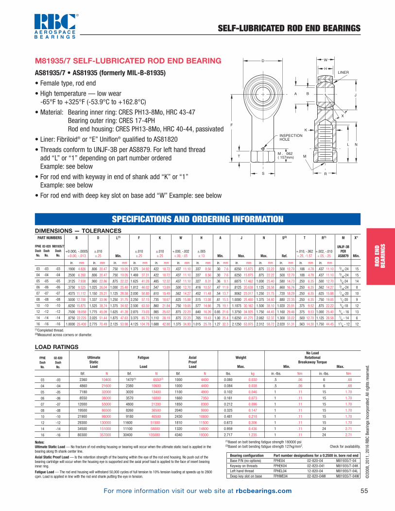
©2008, 2011, 2016 RBC Bearings Incorporated. All rights reserved.
For more information visit our web site at rbcbearings.com
SELF-LUBRICATED ROD END BEARINGS
55
ROD
END
BEAR
INGS
LOAD RATINGS
lbf. N lbf. N lbf. N lbs. kg in.-lbs. Nm in.-lbs. Nm
2360 10400 1470(1) 6550(2) 1000 4400 0.080 0.030 .5 .06 6 .68
4860 21600 2380 10600 1000 4400 0.084 0.038 .5 .06 6 .68
7180 32000 3020 13400 1100 4900 0.102 0.046 1 .11 15 1.70
8550 38000 3570 16000 1660 7350 0.161 0.073 1 .11 15 1.70
12000 53000 4800 21200 1850 8300 0.212 0.096 1 .11 15 1.70
19500 86500 8260 36500 2040 9000 0.325 0.147 1 .11 15 1.70
21900 98000 9180 40500 2430 10800 0.481 0.218 1 .11 15 1.70
29300 130000 11600 51500 1810 11500 0.673 0.306 1 .11 15 1.70
34500 151000 11100 58000 1320 14800 0.959 0.436 1 .11 24 2.71
80300 357000 30400 135000 4340 19300 2.717 1.235 1 .11 24 2.71
(1)Based on bolt bending fatigue strength 180000 psi(2)Based on bolt bending fatigue strength 127kg/mm2. Check for availability.
UltimateStaticLoad
No LoadRotational
Breakaway TorqueMin. Max.
Weight
Max.
AxialProofLoad
Fatigue
Load
FPHE 02-820Dash DashNo. No.
03 -03
04 -04
05 -05
06 -06
07 -07
08 -08
10 -10
12 -12
14 -14
16 -16
AS81935/7 • AS81935 (formerly MIL-B-81935)• Female type, rod end
• High temperature — low wear -65°F to +325°F (-53.9°C to +162.8°C)
• Material: Bearing inner ring: CRES PH13-8Mo, HRC 43-47Bearing outer ring: CRES 17-4PHRod end housing: CRES PH13-8Mo, HRC 40-44, passivated
• Liner: Fibriloid® or “E” Uniflon® qualified to AS81820
• Threads conform to UNJF-3B per AS8879. For left hand thread add “L” or “1” depending on part number orderedExample: see below
• For rod end with keyway in end of shank add “K” or “1”Example: see below
• For rod end with deep key slot on base add “W” Example: see below
M81935/7 SELF-LUBRICATED ROD END BEARING D
F
T
S
M . 062
( 157mm)
INSPECTION
HOLE
R
A
W
H
LINER
B
X
L N
K
M
J
Notes:Ultimate Static Load — No fracture of rod ending housing or bearing will occur when the ultimate static load is applied in thebearing along th shank center line.
Axial Static Proof Load— Is the retention strength of the bearing within the eye of the rod end housing. No push out of thebearing cartridge will occur when the housing eye is supported and the axial proof load is applied to the face of insert bearinginner ring.
Fatigue Load— The rod end housing will withstand 50,000 cycles of full tension to 10% tension loading at speeds up to 2800cpm. Load is applied in line with the rod end shank putting the eye in tension.
Bearing configuration Part number designations for a 0.2500 in. bore rod endBase P/N (no options) FPHE04 02-820-04 M81935/7-04Keyway on threads FPHEK04 02-820-041 M81935/7-04KLeft hand thread FPHEL04 12-820-04 M81935/7-04LDeep key slot on base FPHWE04 02-820-04W M81935/7-04W
DIMENSIONS — TOLERANCES
in. mm in. mm in. mm in. mm in. mm in. mm in. mm in. mm in. mm in. mm in. mm in. mm in. mm
.1900 4.826 .806 20.47 .750 19.05 1.375 34.92 .422 10.72 .437 11.10 .337 8.56 .30 7.6 .6250 15.875 .875 22.22 .500 12.70 .188 4.78 .437 11.10 5/16-24 15
.2500 6.350 .806 20.47 .750 19.05 1.469 37.31 .422 10.72 .437 11.10 .337 8.56 .30 7.6 .6250 15.875 .875 22.22 .500 12.70 .188 4.78 .437 11.10 5/16-24 15
.3125 7.938 .900 22.86 .875 22.22 1.625 41.28 .485 12.32 .437 11.10 .327 8.31 .36 9.1 .6875 17.462 1.000 25.40 .580 14.73 .250 6.35 .500 12.70 3/8-24 14
.3750 9.525 1.025 26.04 1.000 25.40 1.812 46.02 .547 13.89 .500 12.70 .416 10.57 .47 11.9 .8125 20.638 1.125 28.58 .660 16.76 .250 6.35 .562 14.27 3/18-24 8
.4375 11.112 1.150 29.21 1.125 28.58 2.000 50.80 .610 15.49 .562 14.27 .452 11.48 .54 13.7 .9062 23.017 1.250 31.75 .720 18.29 .250 6.35 .625 15.88 7/16-20 10
.5000 12.700 1.337 33.96 1.250 31.75 2.250 57.15 .735 18.67 .625 15.88 .515 13.08 .61 15.5 1.0000 25.400 1.375 34.92 .880 22.35 .250 6.35 .750 19.05 1/2-20 9
.6250 15.875 1.525 38.74 1.375 34.92 2.500 63.50 .860 21.84 .750 19.05 .577 14.66 .75 19.1 1.1875 30.162 1.500 38.10 1.020 25.91 .375 9.52 .875 22.22 5/8-18 12
.7500 19.050 1.775 45.09 1.625 41.28 2.875 73.03 .985 25.02 .875 22.23 .640 16.26 0.85 21.6 1.3750 34.925 1.750 44.45 1.160 29.46 .375 9.53 1.000 25.40 3/4 - 16 13
.8750 22.225 2.025 51.44 1.875 47.63 3.375 85.73 1.110 28.19 .875 22.23 .765 19.43 1.00 25.4 1.6250 41.275 2.062 52.37 1.300 33.02 .500 12.70 1.125 28.58 7/8 - 14 6
1.0000 25.400 2.775 70.49 2.125 53.98 4.125 104.78 1.688 42.88 1.375 34.93 1.015 25.78 1.27 32.3 2.1250 53.975 2.312 58.72 2.020 51.31 .563 14.30 1.750 44.45 11/4 - 12 12(1)Completed thread. (2)Measured across corners or diameter.
S(2)
Ref.
N
Max.
J
Max.
A
Min.
K
±.010 ±.25
F
±.010 ±.25
R(1)
+.002, -.010 +.05, -.25
T
+.010, -.062 +.25, -1.57
X°
Min.
M
UNJF-3BPER
AS8879
H
±.005 ±.13
W
+.000, -.002 +.00, -.05
L(1)
Min.
D
±.010±.25
B
+0.000, -.0005 +0.00, -.013
PART NUMBERS
FPHE 02-820 M81935/7Dash Dash DashNo. No. No.
03 -03 -03
04 -04 -04
05 -05 -05
06 -06 -06
07 -07 -07
08 -08 -08
10 -10 -10
12 -12 -12
14 -14 -14
16 -16 -16
SPECIFICATIONS AND ORDERING INFORMATION
PB_049_072_8-29-16_Pln_051_078.qxd 8/30/16 11:04 AM Page 55
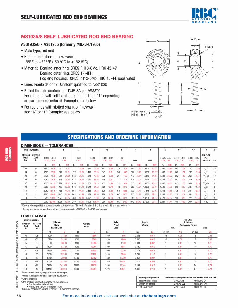
©2008, 2011, 2016 RBC Bearings Incorporated. All rights reserved.
For more information visit our web site at rbcbearings.com
SELF-LUBRICATED ROD END BEARINGS
56
ROD
END
BEAR
INGS
AS81935/8 • AS81935 (formerly MIL-B-81935)• Male type, rod end
• High temperature — low wear -65°F to +325°F (-53.9°C to +162.8°C)
• Material: Bearing inner ring: CRES PH13-8Mo, HRC 43-47Bearing outer ring: CRES 17-4PHRod end housing: CRES PH13-8Mo, HRC 40-44, passivated
• Liner: Fibriloid® or “E” Uniflon® qualified to AS81820
• Rolled threads conform to UNJF-3A per AS8879For rod ends with left hand thread add “L” or “1” depending on part number ordered. Example: see below
• For rod ends with slotted shank or “keyway” add “K” or “1” Example: see below
M81935/8 SELF-LUBRICATED ROD END BEARING
LOAD RATINGS
lbf. N lbf. N lbf. N lbs. kg in.-lbs. Nm in.-lbs. Nm
03 -03 1000 11320 1100 4884 150 666 0.038 0.017 0.5 0.06 6 0.68
04 -04 5300 21532 1500 6660 430 1909 0.045 0.020 0.5 0.06 6 0.68
05 -05 8600 38184 1400 10656 700 1108 0.081 0.037 1 0.11 15 1.70
06 -06 11000 57720 1600 15984 1100 4884 0.120 0.055 1 0.11 15 1.70
07 -07 17800 79032 5000 21200 1400 6216 0.172 0.078 1 0.11 15 1.70
08 -08 24200 107448 6800 30192 1040 9058 0.254 0.115 1 0.11 15 1.70
10 -10 38500 170940 10800 47952 1430 10789 0.455 0.207 1 0.11 15 1.70
12 -12 56600 251304 16000 71040 1940 11054 0.774 0.352 1 0.11 15 1.70
14 -14 77400 341656 21900 97236 1190 14164 1.141 0.519 1 0.11 24 2.71
16 -16 101400 450216 28600 126984 1570 15851 1.646 0.748 1 0.11 24 2.71(1)Based on bolt bending fatigue strength 180000 psi(2)Based on bolt bending fatigue strength 127kg/mm2. (3)Shank limitation Notes: For liner specifications or the following options:
• Stainless steel rod end body• High temperature or high speed liners
Please see engineering section or contact RBC Aerospace Bearings.
UltimateStatic
Radial Load
No LoadRotational
Breakaway TorqueMin. Max.
Approx.Weight
AxialProofLoad
FatigueLoad
PART NUMBERSMPHE-ANDashNo.
M81935/8DashNo.
Bearing configuration Part number designations for a 0.2500 in. bore rod endBase P/N (no options) MPHE04AN M81935/8-04Keyway on threads MPHEK04AN M81935/8-04KLeft hand thread MPHEL04AN M81935/8-04L
SPECIFICATIONS AND ORDERING INFORMATION
F
015 (0.38mm)
005 (0.13mm)
L G
P
M
K
R
A B J
LINER
X
DW
H
DIMENSIONS — TOLERANCES
in. mm in. mm in. mm in. mm in. mm in. mm in. mm in. mm in. mm in. mm in. mm
.1900 4.826 .680 17.27 .775 19.69 1.315 33.40 .281 7.14 .228 5.79 .293 7.44 .6250 15.875 .896 22.76 .062 1.57 .207 5.26 1/4-28 10
.2500 6.350 .827 21.01 .775 19.69 1.443 36.65 .343 8.71 .260 6.60 .364 9.25 .6250 15.875 .896 22.76 .062 1.57 .207 5.26 1/4-28 10
.3125 7.938 .984 24.99 1.187 30.15 1.948 49.48 .375 9.53 .291 7.39 .419 10.64 .6875 17.462 1.308 33.22 .062 1.57 .268 6.81 5/16-24 10
.3750 9.525 1.131 28.73 1.187 30.15 2.030 51.56 .406 10.31 .322 8.18 .475 12.07 .8125 20.638 1.308 33.22 .093 2.36 .319 8.10 3/8-24 9
.4375 11.112 1.294 32.87 1.281 32.54 2.250 57.15 .437 11.10 .353 8.97 .530 13.46 .9062 23.017 1.402 35.61 .093 2.36 .383 9.73 7/16-20 8
.5000 12.700 1.459 37.06 1.462 37.13 2.544 64.62 .500 12.70 .400 10.16 .600 15.24 1.0000 25.400 1.589 40.36 .093 2.36 .445 11.30 1/2-20 8
.6250 15.875 1.763 44.78 1.582 40.18 2.832 71.93 .625 15.88 .510 12.95 .739 18.77 1.1875 30.162 1.683 42.75 .125 3.18 .541 13.74 5/8-18 8
.7500 19.050 2.140 54.36 1.687 42.85 3.193 81.10 .750 19.05 .603 15.32 .920 23.37 1.3750 34.925 1.808 45.92 .125 3.18 .663 16.84 3/4-16 8
.8750 22.225 2.372 60.25 2.000 50.80 3.677 93.40 .875 22.23 .713 18.11 .980 24.89 1.6250 41.275 2.121 53.87 .156 3.96 .777 19.74 7/8-14 8
1.0000 25.400 2.681 68.10 2.100 53.34 3.988 101.30 1.000 25.40 .807 20.50 1.118 28.40 2.1250 53.975 2.221 56.41 .156 3.96 .900 22.86 1-12 9(1)Keyway when specified, is compatible with locking devices, AS81935/3 for sizes 3 thru 8, and NAS559 for sizes 10 thru 16.
Keyway tolerances not specified shall be in accordance with AS81935/3 or NAS513 as applicable.
P(1)
+.000, -.005 +.00, -.13
K(1)
+.005, -.000 +.13, -.00
G
+.000, -.020 +.00, -.51
J
Max.
X°
Min.
M
UNJF-3APER
AS8879
A
Min.
H
±.005 ±.13
W
+.000, -.002 +.00, -.05
F
±.010 ±.25
L
±.031 ±.79
D
±.010±.25
B
+0.000, -.0005 +0.00, -.013
PART NUMBERS
MPHE-AN M81935/8Dash DashNo. No.
03 -03
04 -04
05 -05
06 -06
07 -07
08 -08
10 -10
12 -12
14 -14
16 -16
PB_049_072_8-29-16_Pln_051_078.qxd 8/30/16 11:05 AM Page 56
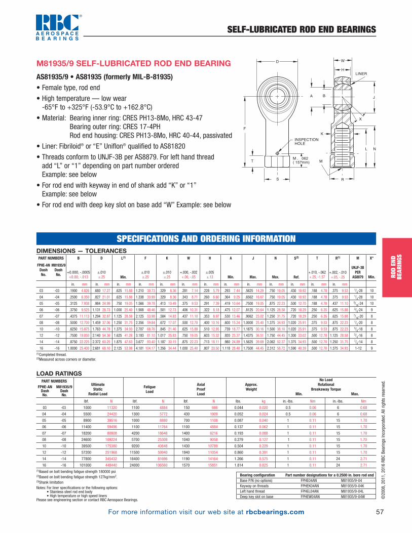
©2008, 2011, 2016 RBC Bearings Incorporated. All rights reserved.
For more information visit our web site at rbcbearings.com
SELF-LUBRICATED ROD END BEARINGS
57
ROD
END
BEAR
INGS
DIMENSIONS — TOLERANCES
in. mm in. mm in. mm in. mm in. mm in. mm in. mm in. mm in. mm in. mm in. mm in. mm in. mm
.1900 4.826 .680 17.27 .625 15.88 1.210 30.73 .329 8.36 .281 7.14 .228 5.79 .293 7.44 .5625 14.29 .750 19.05 .430 10.92 .188 4.78 .375 9.53 1/4-28 10
.2500 6.350 .827 21.01 .625 15.88 1.338 33.99 .329 8.36 .343 8.71 .260 6.60 .364 9.25 .6562 16.67 .750 19.05 .430 10.92 .188 4.78 .375 9.53 1/4-28 10
.3125 7.938 .984 24.99 .750 19.05 1.566 39.78 .413 10.49 .375 9.53 .291 7.39 .419 10.64 .7500 19.05 .875 22.23 .500 12.70 .188 4.78 .437 11.10 5/16-24 10
.3750 9.525 1.131 28.73 1.000 25.40 1.908 48.46 .501 12.73 .406 10.31 .322 8.18 .475 12.07 .8125 20.64 1.125 28.58 .720 18.29 .250 6.35 .625 15.88 3/8-24 9
.4375 11.113 1.294 32.87 1.125 28.58 2.125 53.98 .584 14.83 .437 11.10 .353 8.97 .530 13.46 .9062 23.02 1.250 31.75 .720 18.29 .250 6.35 .625 15.88 7/16-20 8
.5000 12.700 1.459 37.06 1.250 31.75 2.356 59.84 .672 17.07 .500 12.70 .400 10.16 .600 15.24 1.0000 25.40 1.375 34.93 1.020 25.91 .375 9.53 .875 22.23 1/2-20 8
.6250 15.875 1.763 44.78 1.375 34.93 2.707 68.76 .845 21.46 .625 15.88 .510 12.95 .739 18.77 1.1875 30.16 1.500 38.10 1.020 25.91 .375 9.53 .875 22.23 5/8-18 8
.7500 19.050 2.140 54.36 1.625 41.28 3.193 81.10 1.017 25.83 .750 19.05 .603 15.32 .920 23.37 1.4375 36.51 1.750 44.45 1.300 33.02 .500 12.70 1.125 28.58 3/4-16 8
.8750 22.225 2.372 60.25 1.875 47.63 3.677 93.40 1.187 30.15 .875 22.23 .713 18.11 .980 24.89 1.5625 39.69 2.062 52.37 1.375 34.93 .500 12.70 1.250 31.75 7/8-14 8
1.0000 25.400 2.681 68.10 2.125 53.98 4.101 104.17 1.356 34.44 1.000 25.40 .807 20.50 1.118 28.40 1.7500 44.45 2.312 58.72 1.590 40.39 .500 12.70 1.375 34.93 1-12 9(1)Completed thread. (2)Measured across corners or diameter.
S(2)
Ref.
N
Max.
J
Max.
A
Min.
K
±.010 ±.25
F
±.010 ±.25
M81935/9DashNo.
FPHE-ANDashNo.
R(1)
+.002, -.010 +.05, -.25
T
+.010, -.062 +.25, -1.57
X°
Min.
M
UNJF-3BPER
AS8879
H
±.005 ±.13
W
+.000, -.002 +.00, -.05
L(1)
Min.
D
±.010±.25
B
+0.000, -.0005 +0.00, -.013
PART NUMBERS
03 -03
04 -04
05 -05
06 -06
07 -07
08 -08
10 -10
12 -12
14 -14
16 -16
SPECIFICATIONS AND ORDERING INFORMATION
AS81935/9 • AS81935 (formerly MIL-B-81935)• Female type, rod end
• High temperature — low wear -65°F to +325°F (-53.9°C to +162.8°C)
• Material: Bearing inner ring: CRES PH13-8Mo, HRC 43-47Bearing outer ring: CRES 17-4PHRod end housing: CRES PH13-8Mo, HRC 40-44, passivated
• Liner: Fibriloid® or “E” Uniflon® qualified to AS81820
• Threads conform to UNJF-3B per AS8879. For left hand thread add “L” or “1” depending on part number orderedExample: see below
• For rod end with keyway in end of shank add “K” or “1”Example: see below
• For rod end with deep key slot on base add “W” Example: see below
M81935/9 SELF-LUBRICATED ROD END BEARING
LOAD RATINGS
lbf. N lbf. N lbf. N lbs. kg in.-lbs. Nm in.-lbs. Nm
03 -03 1000 11320 1100 4884 150 666 0.044 0.020 0.5 0.06 6 0.68
04 -04 5500 24420 1300 5772 430 1909 0.052 0.024 0.5 0.06 6 0.68
05 -05 8900 39516 1000 8880 700 1108 0.087 0.040 1 0.11 15 1.70
06 -06 11400 59496 1100 11764 1100 4884 0.137 0.062 1 0.11 15 1.70
07 -07 18200 80808 4200 18648 1400 6216 0.193 0.088 1 0.11 15 1.70
08 -08 24600 109224 5700 25308 1040 9058 0.279 0.127 1 0.11 15 1.70
10 -10 39500 175380 9200 40848 1430 10789 0.504 0.229 1 0.11 15 1.70
12 -12 57200 251968 11500 59940 1940 11054 0.860 0.391 1 0.11 15 1.70
14 -14 77800 345432 18400 81696 1190 14164 1.266 0.575 1 0.11 24 2.71
16 -16 101000 448440 24000 106560 1570 15851 1.814 0.825 1 0.11 24 2.71(1)Based on bolt bending fatigue strength 180000 psi(2)Based on bolt bending fatigue strength 127kg/mm2. (3)Shank limitation Notes: For liner specifications or the following options:
• Stainless steel rod end body• High temperature or high speed liners
Please see engineering section or contact RBC Aerospace Bearings.
UltimateStatic
Radial Load
No LoadRotational
Breakaway TorqueMin. Max.
Approx.Weight
AxialProofLoad
FatigueLoad
PART NUMBERSFPHE-ANDashNo.
M81935/9DashNo.
Bearing configuration Part number designations for a 0.2500 in. bore rod endBase P/N (no options) FPHE04AN M81935/9-04Keyway on threads FPHEK04AN M81935/9-04KLeft hand thread FPHEL04AN M81935/9-04LDeep key slot on base FPHEW04AN M81935/9-04W
D
F
T
S
M . 062
( 157mm)
INSPECTION
HOLE
R
A
W
H
LINER
B
X
L N
K
M
J
PB_049_072_8-29-16_Pln_051_078.qxd 8/30/16 11:05 AM Page 57
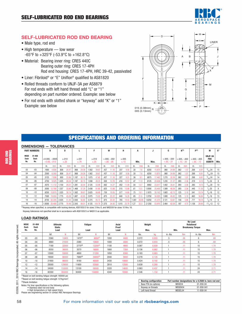
For more information visit our web site at rbcbearings.com
SELF-LUBRICATED ROD END BEARINGS
58
ROD
END
BEAR
INGS
©2008, 2011, 2016 RBC Bearings Incorporated. All rights reserved.
• Male type, rod end
• High temperature — low wear -65°F to +325°F (-53.9°C to +162.8°C)
• Material: Bearing inner ring: CRES 440CBearing outer ring: CRES 17-4PHRod end housing: CRES 17-4PH, HRC 39-42, passivated
• Liner: Fibriloid® or “E” Uniflon® qualified to AS81820
• Rolled threads conform to UNJF-3A per AS8879For rod ends with left hand thread add “L” or “1” depending on part number ordered. Example: see below
• For rod ends with slotted shank or “keyway” add “K” or “1” Example: see below
SELF-LUBRICATED ROD END BEARING
LOAD RATINGS
lbf. N lbf. N lbf. N lbs. kg in.-lbs. Nm in.-lbs. Nm
2360 10400 1470(1) 6550(2) 1000 4400 0.072 0.033 .5 .06 6 .68
4860 21600 2380 10600 1000 4400 0.072 0.033 .5 .06 6 .68
7180 32000 2770(3) 12200(3) 1100 4900 0.087 0.039 1 .11 15 1.70
8550 38000 3570 16000 1660 7350 0.136 0.062 1 .11 15 1.70
12000 53000 4800 21200 1850 8300 0.183 0.083 1 .11 15 1.70
19500 86500 7680(3) 34000(3) 2040 9000 0.278 0.126 1 .11 15 1.70
21900 98000 9180 40500 2430 10800 0.424 0.192 1 .11 15 1.70
29300 129000 11600 52000 2810 12500 0.639 0.290 1 .11 15 1.70
34500 153000 13100 58500 3320 14600 0.963 0.437 1 .11 24 2.71
80300 355000 30400 134000 4340 19300 2.546 1.150 1 .11 24 2.71(1)Based on bolt bending fatigue strength 180000 psi(2)Based on bolt bending fatigue strength 127kg/mm2. (3)Shank limitation Notes: For liner specifications or the following options:
• Stainless steel rod end body• High temperature or high speed liners
Please see engineering section or contact RBC Aerospace Bearings.
UltimateStaticLoad
No LoadRotational
Breakaway TorqueMin. Max.
Weight
Max.
AxialProofLoad
Fatigue
Load
DIMENSIONS — TOLERANCES
in. mm in. mm in. mm in. mm in. mm in. mm in. mm in. mm in. mm in. mm in. mm
.1900 4.826 .806 20.47 .968 24.59 1.562 39.67 .437 11.10 .337 8.56 .30 7.6 .6250 15.875 .980 24.89 .062 1.57 .268 6.81 5/16-24 15
.2500 6.350 .806 20.47 .968 24.59 1.562 39.67 .437 11.10 .337 8.56 .30 7.6 .6250 15.875 .980 24.89 .062 1.57 .268 6.81 5/16-24 15
.3125 7.938 .900 22.86 1.187 30.15 1.875 47.62 .437 11.10 .327 8.31 .36 9.1 .6875 17.462 1.270 32.26 .062 1.57 .268 6.81 5/16-24 14
.3750 9.525 1.025 26.04 1.187 30.15 1.938 49.23 .500 12.70 .416 10.57 .47 11.9 .8125 20.638 1.235 31.37 .093 2.36 .319 8.10 3/8-24 8
.4375 11.112 1.150 29.21 1.281 32.54 2.125 53.98 .562 14.27 .452 11.48 .54 13.7 .9062 23.017 1.402 35.61 .093 2.36 .383 9.73 7/16-20 10
.5000 12.700 1.337 33.96 1.468 37.29 2.438 61.93 .625 15.88 .515 13.08 .61 15.5 1.0000 25.400 1.589 40.36 .093 2.36 .445 11.30 1/2-20 9
.6250 15.875 1.525 38.74 1.562 39.67 2.625 66.68 .750 19.05 .577 14.66 .75 19.1 1.1875 30.162 1.683 42.75 .125 3.18 .541 13.74 5/8-18 12
.7500 19.050 1.775 45.08 1.687 42.85 2.875 73.02 .875 22.22 .640 16.26 .85 21.6 1.3750 34.925 1.808 45.92 .125 3.18 .663 16.84 3/4-16 13
.8750 22.225 2.025 51.44 2.000 50.80 3.375 85.72 .875 22.22 .765 19.43 1.061 26.95 1.6250 41.275 2.121 53.87 .156 3.96 .777 19.74 7/8-14 6
1.0000 25.400 2.775 70.48 2.343 59.51 4.125 104.78 1.375 34.92 1.015 25.78 1.27 32.3 2.1250 53.975 2.464 62.59 .187 4.75 1.136 28.85 11/4-12 12(1)Keyway when specified, is compatible with locking devices, AS81935/3 for sizes 3 thru 8, and NAS559 for sizes 10 thru 16.
Keyway tolerances not specified shall be in accordance with AS81935/3 or NAS513 as applicable.
P(1)
+.000, -.005 +.00, -.13
K(1)
+.005, -.000 +.13, -.00
G
+.000, -.020 +.00, -.51
J
Max.
X°
Min.
M
UNJF-3APER
AS8879
A
Min.
H
±.005 ±.13
W
+.000, -.002 +.00, -.05
F
±.010 ±.25
L
±.031 ±.79
D
±.010±.25
B
+0.000, -.0005 +0.00, -.013
PART NUMBERS
MSSE 01-858Dash DashNo. No.
03 -03
04 -04
05 -05
06 -06
07 -07
08 -08
10 -10
12 -12
14 -14
16 -16
MSSE 01-858Dash DashNo. No.
03 -03
04 -04
05 -05
06 -06
07 -07
08 -08
10 -10
12 -12
14 -14
16 -16
Bearing configuration Part number designations for a 0.2500 in. bore rod endBase P/N (no options) MSSE04 01-858-04Keyway on threads MSSEK04 01-858-041Left hand thread MSSEL04 11-858-04
SPECIFICATIONS AND ORDERING INFORMATION
F
015 (0.38mm)
005 (0.13mm)
L G
P
M
K
R
A B J
LINER
X
DW
H
PB_049_072_8-29-16_Pln_051_078.qxd 8/30/16 11:05 AM Page 58
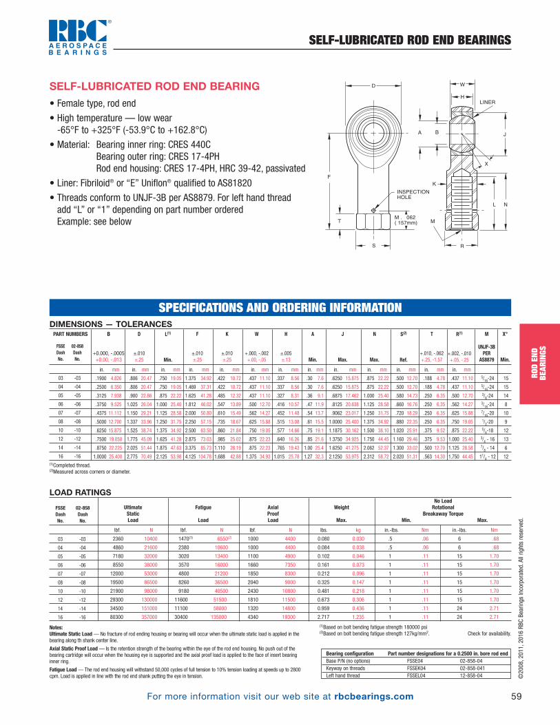
For more information visit our web site at rbcbearings.com
SELF-LUBRICATED ROD END BEARINGS
59
ROD
END
BEAR
INGS
©2008, 2011, 2016 RBC Bearings Incorporated. All rights reserved.
DIMENSIONS — TOLERANCES
in. mm in. mm in. mm in. mm in. mm in. mm in. mm in. mm in. mm in. mm in. mm in. mm in. mm
.1900 4.826 .806 20.47 .750 19.05 1.375 34.92 .422 10.72 .437 11.10 .337 8.56 .30 7.6 .6250 15.875 .875 22.22 .500 12.70 .188 4.78 .437 11.10 5/16-24 15
.2500 6.350 .806 20.47 .750 19.05 1.469 37.31 .422 10.72 .437 11.10 .337 8.56 .30 7.6 .6250 15.875 .875 22.22 .500 12.70 .188 4.78 .437 11.10 5/16-24 15
.3125 7.938 .900 22.86 .875 22.22 1.625 41.28 .485 12.32 .437 11.10 .327 8.31 .36 9.1 .6875 17.462 1.000 25.40 .580 14.73 .250 6.35 .500 12.70 3/8-24 14
.3750 9.525 1.025 26.04 1.000 25.40 1.812 46.02 .547 13.89 .500 12.70 .416 10.57 .47 11.9 .8125 20.638 1.125 28.58 .660 16.76 .250 6.35 .562 14.27 3/18-24 8
.4375 11.112 1.150 29.21 1.125 28.58 2.000 50.80 .610 15.49 .562 14.27 .452 11.48 .54 13.7 .9062 23.017 1.250 31.75 .720 18.29 .250 6.35 .625 15.88 7/16-20 10
.5000 12.700 1.337 33.96 1.250 31.75 2.250 57.15 .735 18.67 .625 15.88 .515 13.08 .61 15.5 1.0000 25.400 1.375 34.92 .880 22.35 .250 6.35 .750 19.05 1/2-20 9
.6250 15.875 1.525 38.74 1.375 34.92 2.500 63.50 .860 21.84 .750 19.05 .577 14.66 .75 19.1 1.1875 30.162 1.500 38.10 1.020 25.91 .375 9.52 .875 22.22 5/8-18 12
.7500 19.050 1.775 45.09 1.625 41.28 2.875 73.03 .985 25.02 .875 22.23 .640 16.26 .85 21.6 1.3750 34.925 1.750 44.45 1.160 29.46 .375 9.53 1.000 25.40 3/4 - 16 13
.8750 22.225 2.025 51.44 1.875 47.63 3.375 85.73 1.110 28.19 .875 22.23 .765 19.43 1.00 25.4 1.6250 41.275 2.062 52.37 1.300 33.02 .500 12.70 1.125 28.58 7/8 - 14 6
1.0000 25.400 2.775 70.49 2.125 53.98 4.125 104.78 1.688 42.88 1.375 34.93 1.015 25.78 1.27 32.3 2.1250 53.975 2.312 58.72 2.020 51.31 .563 14.30 1.750 44.45 11/4 - 12 12(1)Completed thread. (2)Measured across corners or diameter.
S(2)
Ref.
N
Max.
J
Max.
A
Min.
K
±.010 ±.25
F
±.010 ±.25
R(1)
+.002, -.010 +.05, -.25
T
+.010, -.062 +.25, -1.57
X°
Min.
M
UNJF-3BPER
AS8879
H
±.005 ±.13
W
+.000, -.002 +.00, -.05
L(1)
Min.
D
±.010±.25
B
+0.000, -.0005 +0.00, -.013
PART NUMBERS
FSSE 02-858Dash DashNo. No.
03 -03
04 -04
05 -05
06 -06
07 -07
08 -08
10 -10
12 -12
14 -14
16 -16
SPECIFICATIONS AND ORDERING INFORMATION
• Female type, rod end
• High temperature — low wear -65°F to +325°F (-53.9°C to +162.8°C)
• Material: Bearing inner ring: CRES 440CBearing outer ring: CRES 17-4PHRod end housing: CRES 17-4PH, HRC 39-42, passivated
• Liner: Fibriloid® or “E” Uniflon® qualified to AS81820
• Threads conform to UNJF-3B per AS8879. For left hand thread add “L” or “1” depending on part number orderedExample: see below
D
F
T
S
M . 062
( 157mm)
INSPECTION
HOLE
R
A
W
H
LINER
B
X
L N
K
M
J
SELF-LUBRICATED ROD END BEARING
Notes:Ultimate Static Load — No fracture of rod ending housing or bearing will occur when the ultimate static load is applied in thebearing along th shank center line.
Axial Static Proof Load— Is the retention strength of the bearing within the eye of the rod end housing. No push out of thebearing cartridge will occur when the housing eye is supported and the axial proof load is applied to the face of insert bearinginner ring.
Fatigue Load— The rod end housing will withstand 50,000 cycles of full tension to 10% tension loading at speeds up to 2800cpm. Load is applied in line with the rod end shank putting the eye in tension.
Bearing configuration Part number designations for a 0.2500 in. bore rod endBase P/N (no options) FSSE04 02-858-04 Keyway on threads FSSEK04 02-858-041 Left hand thread FSSEL04 12-858-04
LOAD RATINGS
lbf. N lbf. N lbf. N lbs. kg in.-lbs. Nm in.-lbs. Nm
2360 10400 1470(1) 6550(2) 1000 4400 0.080 0.030 .5 .06 6 .68
4860 21600 2380 10600 1000 4400 0.084 0.038 .5 .06 6 .68
7180 32000 3020 13400 1100 4900 0.102 0.046 1 .11 15 1.70
8550 38000 3570 16000 1660 7350 0.161 0.073 1 .11 15 1.70
12000 53000 4800 21200 1850 8300 0.212 0.096 1 .11 15 1.70
19500 86500 8260 36500 2040 9000 0.325 0.147 1 .11 15 1.70
21900 98000 9180 40500 2430 10800 0.481 0.218 1 .11 15 1.70
29300 130000 11600 51500 1810 11500 0.673 0.306 1 .11 15 1.70
34500 151000 11100 58000 1320 14800 0.959 0.436 1 .11 24 2.71
80300 357000 30400 135000 4340 19300 2.717 1.235 1 .11 24 2.71
(1)Based on bolt bending fatigue strength 180000 psi(2)Based on bolt bending fatigue strength 127kg/mm2. Check for availability.
UltimateStaticLoad
No LoadRotational
Breakaway TorqueMin. Max.
Weight
Max.
AxialProofLoad
Fatigue
Load
FSSE 02-858Dash DashNo. No.
03 -03
04 -04
05 -05
06 -06
07 -07
08 -08
10 -10
12 -12
14 -14
16 -16
PB_049_072_8-29-16_Pln_051_078.qxd 8/30/16 11:05 AM Page 59
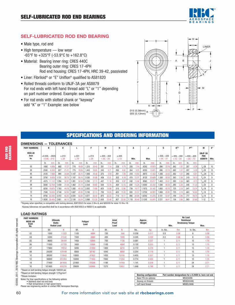
For more information visit our web site at rbcbearings.com
SELF-LUBRICATED ROD END BEARINGS
60
ROD
END
BEAR
INGS
©2008, 2011, 2016 RBC Bearings Incorporated. All rights reserved.
• Male type, rod end
• High temperature — low wear -65°F to +325°F (-53.9°C to +162.8°C)
• Material: Bearing inner ring: CRES 440CBearing outer ring: CRES 17-4PHRod end housing: CRES 17-4PH, HRC 39-42, passivated
• Liner: Fibriloid® or “E” Uniflon® qualified to AS81820
• Rolled threads conform to UNJF-3A per AS8879For rod ends with left hand thread add “L” or “1” depending on part number ordered. Example: see below
• For rod ends with slotted shank or “keyway” add “K” or “1” Example: see below
SELF-LUBRICATED ROD END BEARING
LOAD RATINGS
lbf. N lbf. N lbf. N lbs. kg in.-lbs. Nm in.-lbs. Nm
03 1000 11320 1100 4884 150 666 0.038 0.017 0.5 0.06 6 0.68
04 5300 21532 1500 6660 430 1909 0.045 0.020 0.5 0.06 6 0.68
05 8600 38184 1400 10656 700 1108 0.081 0.037 1 0.11 15 1.70
06 11000 57720 1600 15984 1100 4884 0.120 0.055 1 0.11 15 1.70
07 17800 79032 5000 21200 1400 6216 0.172 0.078 1 0.11 15 1.70
08 24200 107448 6800 30192 1040 9058 0.254 0.115 1 0.11 15 1.70
10 38500 170940 10800 47952 1430 10789 0.455 0.207 1 0.11 15 1.70
12 56600 251304 16000 71040 1940 11054 0.774 0.352 1 0.11 15 1.70
14 77400 341656 21900 97236 1190 14164 1.141 0.519 1 0.11 24 2.71
16 101400 450216 28600 126984 1570 15851 1.646 0.748 1 0.11 24 2.71(1)Based on bolt bending fatigue strength 180000 psi(2)Based on bolt bending fatigue strength 127kg/mm2. (3)Shank limitation Notes: For liner specifications or the following options:
• Stainless steel rod end body• High temperature or high speed liners
Please see engineering section or contact RBC Aerospace Bearings.
UltimateStatic
Radial Load
No LoadRotational
Breakaway TorqueMin. Max.
Approx.Weight
AxialProofLoad
FatigueLoad
PART NUMBERSMSSE-AN DashNo.
Bearing configuration Part number designations for a 0.2500 in. bore rod endBase P/N (no options) MSSE04ANKeyway on threads MSSEK04ANLeft hand thread MSSEL04AN
SPECIFICATIONS AND ORDERING INFORMATION
F
015 (0.38mm)
005 (0.13mm)
L G
P
M
K
R
A B J
LINER
X
DW
H
DIMENSIONS — TOLERANCES
in. mm in. mm in. mm in. mm in. mm in. mm in. mm in. mm in. mm in. mm in. mm
.1900 4.826 .680 17.27 .775 19.69 1.315 33.40 .281 7.14 .228 5.79 .293 7.44 .6250 15.875 .896 22.76 .062 1.57 .207 5.26 1/4-28 10
.2500 6.350 .827 21.01 .775 19.69 1.443 36.65 .343 8.71 .260 6.60 .364 9.25 .6250 15.875 .896 22.76 .062 1.57 .207 5.26 1/4-28 10
.3125 7.938 .984 24.99 1.187 30.15 1.948 49.48 .375 9.53 .291 7.39 .419 10.64 .6875 17.462 1.308 33.22 .062 1.57 .268 6.81 5/16-24 10
.3750 9.525 1.131 28.73 1.187 30.15 2.030 51.56 .406 10.31 .322 8.18 .475 12.07 .8125 20.638 1.308 33.22 .093 2.36 .319 8.10 3/8-24 9
.4375 11.112 1.294 32.87 1.281 32.54 2.250 57.15 .437 11.10 .353 8.97 .530 13.46 .9062 23.017 1.402 35.61 .093 2.36 .383 9.73 7/16-20 8
.5000 12.700 1.459 37.06 1.462 37.13 2.544 64.62 .500 12.70 .400 10.16 .600 15.24 1.0000 25.400 1.589 40.36 .093 2.36 .445 11.30 1/2-20 8
.6250 15.875 1.763 44.78 1.582 40.18 2.832 71.93 .625 15.88 .510 12.95 .739 18.77 1.1875 30.162 1.683 42.75 .125 3.18 .541 13.74 5/8-18 8
.7500 19.050 2.140 54.36 1.687 42.85 3.193 81.10 .750 19.05 .603 15.32 .920 23.37 1.3750 34.925 1.808 45.92 .125 3.18 .663 16.84 3/4-16 8
.8750 22.225 2.372 60.25 2.000 50.80 3.677 93.40 .875 22.23 .713 18.11 .980 24.89 1.6250 41.275 2.121 53.87 .156 3.96 .777 19.74 7/8-14 8
1.0000 25.400 2.681 68.10 2.100 53.34 3.988 101.30 1.000 25.40 .807 20.50 1.118 28.40 2.1250 53.975 2.221 56.41 .156 3.96 .900 22.86 1-12 9(1)Keyway when specified, is compatible with locking devices, AS81935/3 for sizes 3 thru 8, and NAS559 for sizes 10 thru 16.
Keyway tolerances not specified shall be in accordance with AS81935/3 or NAS513 as applicable.
P(1)
+.000, -.005 +.00, -.13
K(1)
+.005, -.000 +.13, -.00
G
+.000, -.020 +.00, -.51
J
Max.
X°
Min.
M
UNJF-3APER
AS8879
A
Min.
H
±.005 ±.13
W
+.000, -.002 +.00, -.05
F
±.010 ±.25
L
±.031 ±.79
D
±.010±.25
B
+0.000, -.0005 +0.00, -.013
PART NUMBERS
MSSE-ANDashNo.
03
04
05
06
07
08
10
12
14
16
PB_049_072_8-29-16_Pln_051_078.qxd 8/30/16 11:05 AM Page 60
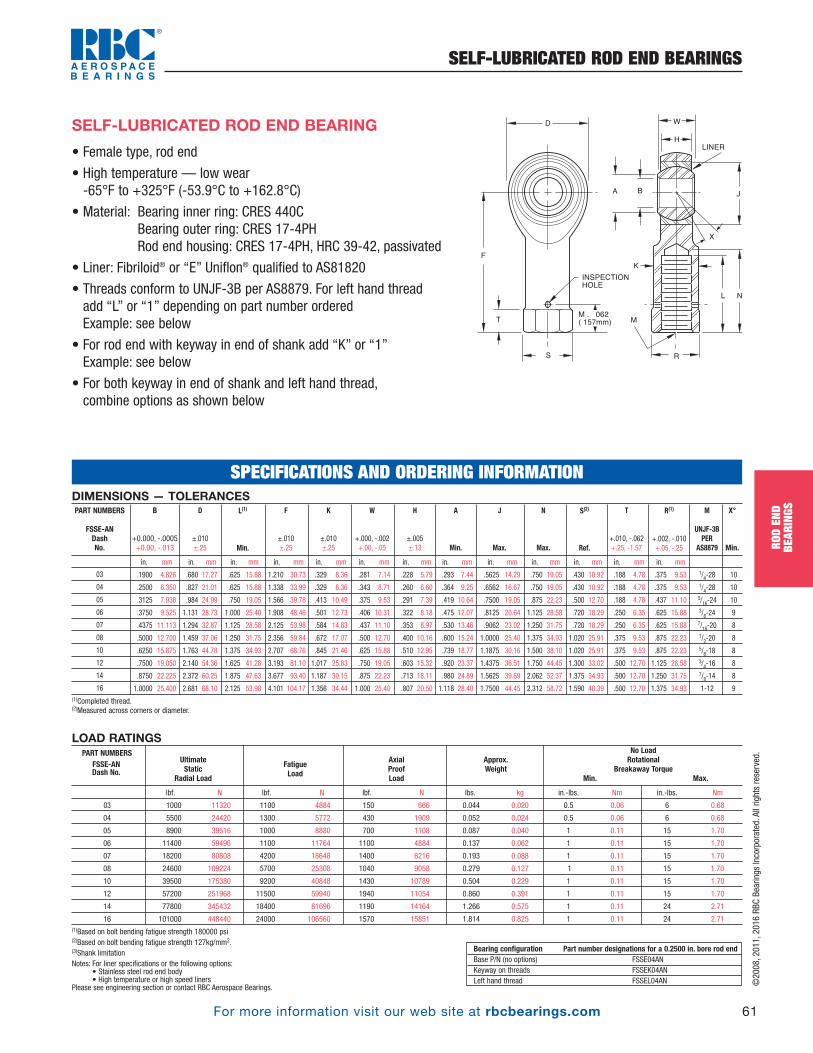
For more information visit our web site at rbcbearings.com
SELF-LUBRICATED ROD END BEARINGS
61
ROD
END
BEAR
INGS
©2008, 2011, 2016 RBC Bearings Incorporated. All rights reserved.
• Female type, rod end
• High temperature — low wear -65°F to +325°F (-53.9°C to +162.8°C)
• Material: Bearing inner ring: CRES 440CBearing outer ring: CRES 17-4PHRod end housing: CRES 17-4PH, HRC 39-42, passivated
• Liner: Fibriloid® or “E” Uniflon® qualified to AS81820
• Threads conform to UNJF-3B per AS8879. For left hand thread add “L” or “1” depending on part number orderedExample: see below
• For rod end with keyway in end of shank add “K” or “1”Example: see below
• For both keyway in end of shank and left hand thread, combine options as shown below
SELF-LUBRICATED ROD END BEARING
LOAD RATINGS
lbf. N lbf. N lbf. N lbs. kg in.-lbs. Nm in.-lbs. Nm
03 1000 11320 1100 4884 150 666 0.044 0.020 0.5 0.06 6 0.68
04 5500 24420 1300 5772 430 1909 0.052 0.024 0.5 0.06 6 0.68
05 8900 39516 1000 8880 700 1108 0.087 0.040 1 0.11 15 1.70
06 11400 59496 1100 11764 1100 4884 0.137 0.062 1 0.11 15 1.70
07 18200 80808 4200 18648 1400 6216 0.193 0.088 1 0.11 15 1.70
08 24600 109224 5700 25308 1040 9058 0.279 0.127 1 0.11 15 1.70
10 39500 175380 9200 40848 1430 10789 0.504 0.229 1 0.11 15 1.70
12 57200 251968 11500 59940 1940 11054 0.860 0.391 1 0.11 15 1.70
14 77800 345432 18400 81696 1190 14164 1.266 0.575 1 0.11 24 2.71
16 101000 448440 24000 106560 1570 15851 1.814 0.825 1 0.11 24 2.71(1)Based on bolt bending fatigue strength 180000 psi(2)Based on bolt bending fatigue strength 127kg/mm2. (3)Shank limitation Notes: For liner specifications or the following options:
• Stainless steel rod end body• High temperature or high speed liners
Please see engineering section or contact RBC Aerospace Bearings.
UltimateStatic
Radial Load
No LoadRotational
Breakaway TorqueMin. Max.
Approx.Weight
AxialProofLoad
FatigueLoad
PART NUMBERSFSSE-AN Dash No.
Bearing configuration Part number designations for a 0.2500 in. bore rod endBase P/N (no options) FSSE04ANKeyway on threads FSSEK04ANLeft hand thread FSSEL04AN
D
F
T
S
M . 062
( 157mm)
INSPECTION
HOLE
R
A
W
H
LINER
B
X
L N
K
M
J
DIMENSIONS — TOLERANCES
in. mm in. mm in. mm in. mm in. mm in. mm in. mm in. mm in. mm in. mm in. mm in. mm in. mm
.1900 4.826 .680 17.27 .625 15.88 1.210 30.73 .329 8.36 .281 7.14 .228 5.79 .293 7.44 .5625 14.29 .750 19.05 .430 10.92 .188 4.78 .375 9.53 1/4-28 10
.2500 6.350 .827 21.01 .625 15.88 1.338 33.99 .329 8.36 .343 8.71 .260 6.60 .364 9.25 .6562 16.67 .750 19.05 .430 10.92 .188 4.78 .375 9.53 1/4-28 10
.3125 7.938 .984 24.99 .750 19.05 1.566 39.78 .413 10.49 .375 9.53 .291 7.39 .419 10.64 .7500 19.05 .875 22.23 .500 12.70 .188 4.78 .437 11.10 5/16-24 10
.3750 9.525 1.131 28.73 1.000 25.40 1.908 48.46 .501 12.73 .406 10.31 .322 8.18 .475 12.07 .8125 20.64 1.125 28.58 .720 18.29 .250 6.35 .625 15.88 3/8-24 9
.4375 11.113 1.294 32.87 1.125 28.58 2.125 53.98 .584 14.83 .437 11.10 .353 8.97 .530 13.46 .9062 23.02 1.250 31.75 .720 18.29 .250 6.35 .625 15.88 7/16-20 8
.5000 12.700 1.459 37.06 1.250 31.75 2.356 59.84 .672 17.07 .500 12.70 .400 10.16 .600 15.24 1.0000 25.40 1.375 34.93 1.020 25.91 .375 9.53 .875 22.23 1/2-20 8
.6250 15.875 1.763 44.78 1.375 34.93 2.707 68.76 .845 21.46 .625 15.88 .510 12.95 .739 18.77 1.1875 30.16 1.500 38.10 1.020 25.91 .375 9.53 .875 22.23 5/8-18 8
.7500 19.050 2.140 54.36 1.625 41.28 3.193 81.10 1.017 25.83 .750 19.05 .603 15.32 .920 23.37 1.4375 36.51 1.750 44.45 1.300 33.02 .500 12.70 1.125 28.58 3/4-16 8
.8750 22.225 2.372 60.25 1.875 47.63 3.677 93.40 1.187 30.15 .875 22.23 .713 18.11 .980 24.89 1.5625 39.69 2.062 52.37 1.375 34.93 .500 12.70 1.250 31.75 7/8-14 8
1.0000 25.400 2.681 68.10 2.125 53.98 4.101 104.17 1.356 34.44 1.000 25.40 .807 20.50 1.118 28.40 1.7500 44.45 2.312 58.72 1.590 40.39 .500 12.70 1.375 34.93 1-12 9(1)Completed thread. (2)Measured across corners or diameter.
S(2)
Ref.
N
Max.
J
Max.
A
Min.
K
±.010 ±.25
F
±.010 ±.25
R(1)
+.002, -.010 +.05, -.25
T
+.010, -.062 +.25, -1.57
X°
Min.
M
UNJF-3BPER
AS8879
H
±.005 ±.13
W
+.000, -.002 +.00, -.05
L(1)
Min.
D
±.010±.25
B
+0.000, -.0005 +0.00, -.013
PART NUMBERS
FSSE-AN Dash No.
03
04
05
06
07
08
10
12
14
16
SPECIFICATIONS AND ORDERING INFORMATION
PB_049_072_8-29-16_Pln_051_078.qxd 8/30/16 11:05 AM Page 61

F
015 (0.38mm)005 (0.13mm)
L
P
M
K
R
A B J
LINER
X
DW
H
For more information visit our web site at rbcbearings.com
SELF-LUBRICATED ROD END BEARINGS
62
ROD
END
BEAR
INGS
©2008, 2011, 2016 RBC Bearings Incorporated. All rights reserved.
• Male type, rod end• High temperature, low wear, -65°F to +325°F (-53.9°C to +162.8°C)• Material: Bearing inner ring: CRES 440C
Bearing outer ring: CRES 17-4PHRod end housing: CRES 17-4PHto 180,000 psi min. tensile strengthExposed surface of rod end housing cadmium plated
• Liner: Fibriloid® or “E” Uniflon® qualified to AS81820• Rolled threads conform to UNJF-3A per MIL-S-8879. For rod ends with left hand thread add “L”
• For rod ends with slotted shank or “keyway” add “K” or “1”• For both keyway and left hand thread, combine options• For normal starting torque requirements add letter “N” or “R” for reduced torque requirements
• For rod ends with longitudinal groove, add letter “K” or “F” for rod ends without groove
EN6056 SELF-LUBRICATED ROD END BEARING
DIMENSIONS — TOLERANCES
in. mm in. mm in. mm in. mm in. mm in. mm in. mm in. mm in. mm in. mm
03 03 0.1900 4.826 0.806 20.47 0.968 24.59 1.562 39.67 0.437 11.10 0.337 8.56 0.300 7.62 0.6250 15.875 0.062 1.575 0.260 6.604 .3125-24 15
04 04 0.2500 6.350 0.806 20.47 0.968 24.59 1.562 39.67 0.437 11.10 0.337 8.56 0.300 7.62 0.6250 15.875 0.062 1.575 0.260 6.604 .3125-24 15
041 041 0.2500 6.350 0.806 20.47 1.787 45.39 2.442 62.03 0.437 11.10 0.337 8.56 0.300 7.62 0.6250 15.875 0.062 1.575 0.260 6.604 .3125-24 15
05 05 0.3125 7.938 0.900 22.86 1.187 30.15 1.875 47.63 0.437 11.10 0.327 8.31 0.360 9.14 0.6875 17.463 0.062 1.575 0.260 6.604 .3125-24 14
051 051 0.3125 7.938 0.900 22.86 1.457 37.01 2.270 57.66 0.437 11.10 0.327 8.31 0.360 9.14 0.6875 17.463 0.062 1.575 0.260 6.604 .3125-24 14
06 06 0.3750 9.525 1.025 26.04 1.187 30.15 1.938 49.23 0.500 12.70 0.416 10.57 0.466 11.84 0.8125 20.638 0.093 2.362 0.311 7.899 .3750-24 8
061 061 0.3750 9.525 1.025 26.04 1.654 42.01 2.422 61.52 0.500 12.70 0.416 10.57 0.466 11.84 0.8125 20.638 0.093 2.362 0.311 7.899 .3750-24 8
07 07 0.4375 11.113 1.150 29.21 1.281 32.54 2.125 53.98 0.562 14.27 0.452 11.48 0.537 13.64 0.9375 23.813 0.093 2.362 0.370 9.398 .4375-20 10
08 08 0.5000 12.700 1.337 33.96 1.468 37.29 2.438 61.93 0.625 15.88 0.515 13.08 0.607 15.42 1.0000 25.400 0.093 2.362 0.436 11.074 .5000-20 9
081 081 0.5000 12.700 1.337 33.96 2.216 56.29 3.144 79.86 0.625 15.88 0.515 13.08 0.607 15.42 1.0000 25.400 0.093 2.362 0.436 11.074 .5000-20 9
10 10 0.6250 15.875 1.525 38.74 1.562 39.67 2.625 66.68 0.750 19.05 0.577 14.66 0.747 18.97 1.1875 30.163 0.125 3.175 0.541 13.741 .6250-18 12
101 101 0.6250 15.875 1.525 38.74 2.110 53.59 3.190 81.03 0.750 19.05 0.577 14.66 0.747 18.97 1.1875 30.163 0.125 3.175 0.541 13.741 .6250-18 12
12 12 0.7500 19.050 1.775 45.09 1.687 42.85 2.875 73.03 0.875 22.23 0.640 16.26 0.845 21.46 1.3750 34.925 0.125 3.175 0.663 16.840 .7500-16 13
14 14 0.8750 22.225 2.025 51.44 2.000 50.80 3.375 85.73 0.875 22.23 0.785 19.94 0.995 25.27 1.6250 41.275 0.156 3.962 0.777 19.736 .8750-14 6
16 16 1.0000 25.400 2.775 70.49 2.343 59.51 4.125 104.78 1.375 34.93 1.015 25.78 1.269 32.23 2.1250 53.975 0.187 4.750 1.136 28.854 1.2500-12 13
M
UNJF-3A
X°
Min.
B
+.0000, - .0005 +.000, -.013
Part Number MSSExx6056 EN6056
Dash DashNo. No.
P
+.000, -.005+.00, -.13
K
+.005, -.000+.13, -.00
H
+.005, -.005±.13, -.13
W
+.000, -.002+.00, -.05
F
+0.010, -.010+0.25, -.25
L
+0.060, -.0300, -0.13
J
max.
A
min.
D
+0.010, -.010+0.25, -.25
LOAD RATINGS
kN lbf kN lbf kN lbf kN lbf Nm in-lbs Nm in-lbs kg lbs.
03 03 20.0 4500 30.0 6700 7.9 1800 4.7 1100 .06- 0.56 0.5- 5.0 0.0- 0.11 0.0- 1.0 0.033 0.07
04 04 20.0 4500 30.0 6700 7.9 1800 4.7 1100 .11- 0.56 1.0- 5.0 0.0- 0.11 0.0- 1.0 0.033 0.07
041 041 20.0 4500 30.0 6700 7.9 1800 4.7 1100 .11- 0.56 1.0- 5.0 0.0- 0.11 0.0- 1.0 0.041 0.09
05 05 20.0 4500 30.0 6700 7.3 1600 4.9 1100 .11- 0.56 1.0- 5.0 0.0- 0.11 0.0- 1.0 0.039 0.09
051 051 20.0 4500 30.0 6700 7.3 1600 4.9 1100 .11- 0.56 1.0- 5.0 0.0- 0.11 0.0- 1.0 0.043 0.09
06 06 29.1 6500 43.6 9800 11.7 2600 6.7 1500 .11- 0.56 1.0- 5.0 0.0- 0.11 0.0- 1.0 0.062 0.14
061 061 29.1 6500 43.6 9800 11.7 2600 6.7 1500 .11- 0.56 1.0- 5.0 0.0- 0.11 0.0- 1.0 0.068 0.15
07 07 31.4 7100 47.1 10600 14.4 3200 8.5 1900 .11- 0.56 1.0- 5.0 .03- 0.15 0.3- 1.3 0.083 0.18
08 08 57.2 12900 85.8 19300 15.4 3500 13.7 3100 .11- 0.56 1.0- 5.0 .03- 0.15 0.3- 1.3 0.126 0.28
081 081 57.2 12900 85.8 19300 15.4 3500 13.7 3100 .11- 0.56 1.0- 5.0 .03- 0.15 0.3- 1.3 0.141 0.31
10 10 66.9 15000 100.4 22600 18.3 4100 15.5 3500 .11- 0.56 1.0- 5.0 .03- 0.15 0.3- 1.3 0.192 0.42
101 101 66.9 15000 100.4 22600 18.3 4100 15.5 3500 .11- 0.56 1.0- 5.0 .03- 0.15 0.3- 1.3 0.212 0.47
12 12 88.2 19800 132.2 29700 22.9 5100 20.4 4600 .11- 0.56 1.0- 5.0 .03- 0.15 0.3- 1.3 0.290 0.64
14 14 102.8 23100 154.2 34700 27.1 6100 23.8 5400 .23- 0.90 2.0- 8.0 .04- 0.25 0.4- 2.2 0.437 0.96
16 16 230.9 51900 348.9 78400 35.4 8000 53.3 12000 .23- 0.90 2.0- 8.0 .04- 0.25 0.4- 2.2 1.150 2.54
ApproxWeight
Starting Torque
Normal Reduced
Fatigue Load
Axial Proof Load
Radial Loads
Limit UltimateLoad Load
Part Number MSSExx6056 EN6056
Dash DashNo. No.
DESIGNATIONEXAMPLE Description Block: ROD-END
Identity Block: EN6056 R 04 N T K
No. of this standard
Thread code
Diameter code
Starting torque
Surface treatment
Longitudinal groove code
SPECIFICATIONS AND ORDERING INFORMATION
Removed G column
PB_049_072_8-29-16_Pln_051_078.qxd 8/30/16 11:05 AM Page 62
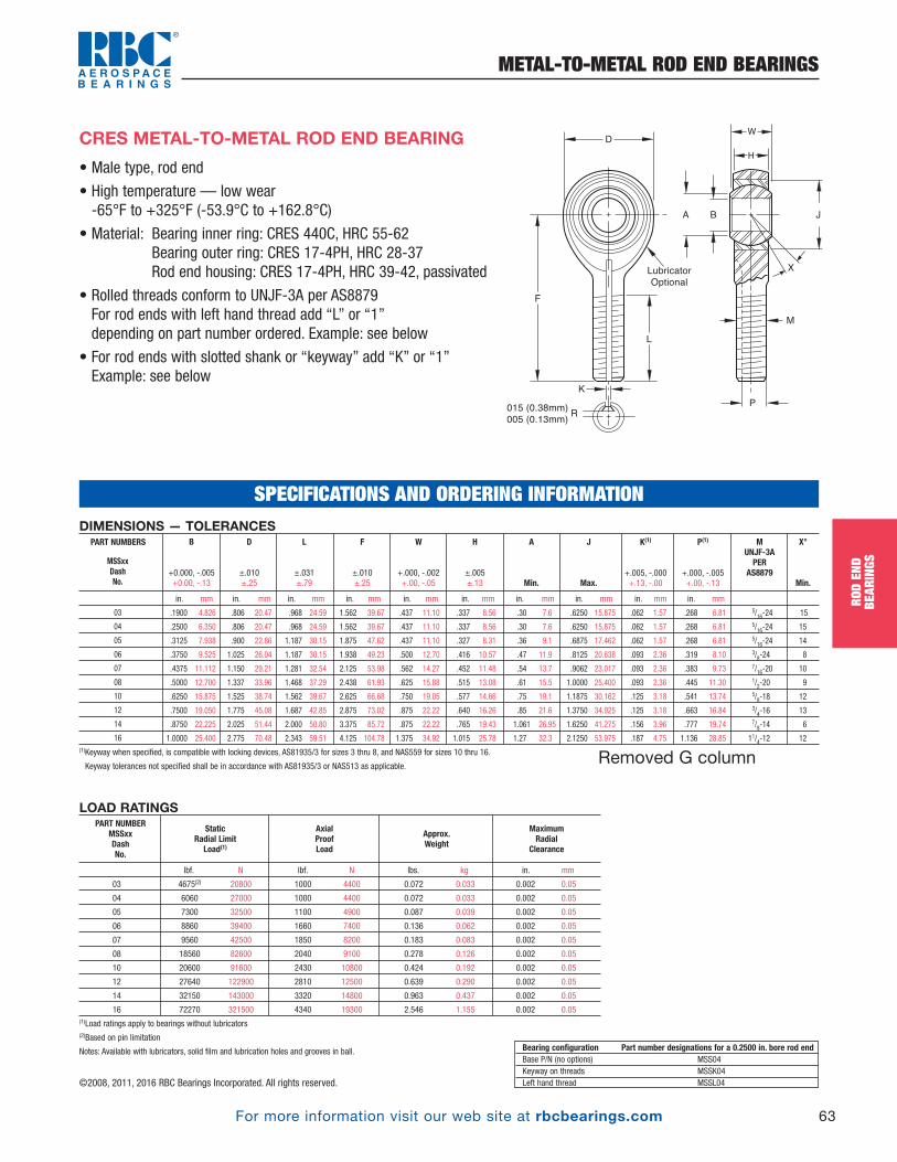
For more information visit our web site at rbcbearings.com
METAL-TO-METAL ROD END BEARINGS
63
ROD
END
BEAR
INGS
©2008, 2011, 2016 RBC Bearings Incorporated. All rights reserved.
LOAD RATINGS
lbf. N lbf. N lbs. kg in. mm
03 4675(2) 20800 1000 4400 0.072 0.033 0.002 0.05
04 6060 27000 1000 4400 0.072 0.033 0.002 0.05
05 7300 32500 1100 4900 0.087 0.039 0.002 0.05
06 8860 39400 1660 7400 0.136 0.062 0.002 0.05
07 9560 42500 1850 8200 0.183 0.083 0.002 0.05
08 18560 82600 2040 9100 0.278 0.126 0.002 0.05
10 20600 91600 2430 10800 0.424 0.192 0.002 0.05
12 27640 122900 2810 12500 0.639 0.290 0.002 0.05
14 32150 143000 3320 14800 0.963 0.437 0.002 0.05
16 72270 321500 4340 19300 2.546 1.155 0.002 0.05(1)Load ratings apply to bearings without lubricators(2)Based on pin limitation
Notes: Available with lubricators, solid film and lubrication holes and grooves in ball.
Static Radial Limit Load(1)
Maximum Radial
Clearance
Approx.Weight
AxialProofLoad
PART NUMBERMSSxx DashNo.
• Male type, rod end
• High temperature — low wear -65°F to +325°F (-53.9°C to +162.8°C)
• Material: Bearing inner ring: CRES 440C, HRC 55-62Bearing outer ring: CRES 17-4PH, HRC 28-37Rod end housing: CRES 17-4PH, HRC 39-42, passivated
• Rolled threads conform to UNJF-3A per AS8879For rod ends with left hand thread add “L” or “1” depending on part number ordered. Example: see below
• For rod ends with slotted shank or “keyway” add “K” or “1” Example: see below
F
015 (0.38mm)005 (0.13mm)
L
P
M
K
R
LubricatorOptional
A B J
X
DW
HCRES METAL-TO-METAL ROD END BEARING
DIMENSIONS — TOLERANCES
in. mm in. mm in. mm in. mm in. mm in. mm in. mm in. mm in. mm in. mm
.1900 4.826 .806 20.47 .968 24.59 1.562 39.67 .437 11.10 .337 8.56 .30 7.6 .6250 15.875 .062 1.57 .268 6.81 5/16-24 15
.2500 6.350 .806 20.47 .968 24.59 1.562 39.67 .437 11.10 .337 8.56 .30 7.6 .6250 15.875 .062 1.57 .268 6.81 5/16-24 15
.3125 7.938 .900 22.86 1.187 30.15 1.875 47.62 .437 11.10 .327 8.31 .36 9.1 .6875 17.462 .062 1.57 .268 6.81 5/16-24 14
.3750 9.525 1.025 26.04 1.187 30.15 1.938 49.23 .500 12.70 .416 10.57 .47 11.9 .8125 20.638 .093 2.36 .319 8.10 3/8-24 8
.4375 11.112 1.150 29.21 1.281 32.54 2.125 53.98 .562 14.27 .452 11.48 .54 13.7 .9062 23.017 .093 2.36 .383 9.73 7/16-20 10
.5000 12.700 1.337 33.96 1.468 37.29 2.438 61.93 .625 15.88 .515 13.08 .61 15.5 1.0000 25.400 .093 2.36 .445 11.30 1/2-20 9
.6250 15.875 1.525 38.74 1.562 39.67 2.625 66.68 .750 19.05 .577 14.66 .75 19.1 1.1875 30.162 .125 3.18 .541 13.74 5/8-18 12
.7500 19.050 1.775 45.08 1.687 42.85 2.875 73.02 .875 22.22 .640 16.26 .85 21.6 1.3750 34.925 .125 3.18 .663 16.84 3/4-16 13
.8750 22.225 2.025 51.44 2.000 50.80 3.375 85.72 .875 22.22 .765 19.43 1.061 26.95 1.6250 41.275 .156 3.96 .777 19.74 7/8-14 6
1.0000 25.400 2.775 70.48 2.343 59.51 4.125 104.78 1.375 34.92 1.015 25.78 1.27 32.3 2.1250 53.975 .187 4.75 1.136 28.85 11/4-12 12(1)Keyway when specified, is compatible with locking devices, AS81935/3 for sizes 3 thru 8, and NAS559 for sizes 10 thru 16.
Keyway tolerances not specified shall be in accordance with AS81935/3 or NAS513 as applicable.
P(1)
+.000, -.005 +.00, -.13
K(1)
+.005, -.000 +.13, -.00
J
Max.
X°
Min.
MUNJF-3APER
AS8879
A
Min.
H
±.005 ±.13
W
+.000, -.002 +.00, -.05
F
±.010 ±.25
L
±.031 ±.79
D
±.010±.25
B
+0.000, -.005 +0.00, -.13
PART NUMBERS
MSSxxDashNo.
03
04
05
06
07
08
10
12
14
16
Bearing configuration Part number designations for a 0.2500 in. bore rod endBase P/N (no options) MSS04Keyway on threads MSSK04Left hand thread MSSL04
SPECIFICATIONS AND ORDERING INFORMATION
Removed G column
PB_049_072_8-29-16_Pln_051_078.qxd 8/30/16 11:05 AM Page 63

For more information visit our web site at rbcbearings.com
METAL-TO-METAL ROD END BEARINGS
64
ROD
END
BEAR
INGS
©2008, 2011, 2016 RBC Bearings Incorporated. All rights reserved.
• Female type, rod end
• High temperature — low wear -65°F to +325°F (-53.9°C to +162.8°C)
• Material: Bearing inner ring: CRES 440C, HRC 55-62Bearing outer ring: CRES 17-4PH, HRC 28-37Rod end housing: CRES 17-4PH, HRC 39-42, passivated
• Threads conform to UNJF-3B per MIL-S-8879. For left hand thread add “L” or “1” depending on part number orderedExample: see below
• For rod end with keyway in end of shank add “K” or “1”Example: see below
D
F
T
S
M . 062
( 157mm)
INSPECTION
HOLE
R
A
W
H
B
X
L N
K
M
J
CRES METAL-TO-METAL ROD END BEARING
Bearing configuration Part number designations for a 0.2500 in. bore rod endBase P/N (no options) FSSE04 Keyway on threads FSSEK04 Left hand thread FSSEL04
LOAD RATINGS
lbf. N lbf. N lbs. kg in. mm
03 -03 4675(1) 20800 1000 4400 0.080 0.036 0.002 0.05
04 -04 6060 27000 1000 4400 0.084 0.038 0.002 0.05
05 -05 7300 32500 1100 4900 0.102 0.046 0.002 0.05
06 -06 8860 39400 1660 7400 0.161 0.073 0.002 0.05
07 -07 9560 42500 1850 8200 0.212 0.096 0.002 0.05
08 -08 18560 82600 2040 9100 0.325 0.147 0.002 0.05
10 -10 20600 91600 2430 10800 0.481 0.218 0.002 0.05
12 -12 27640 122900 2810 12500 0.673 0.305 0.002 0.05
14 -14 32150 143000 3320 14800 0.963 0.437 0.002 0.05
16 -16 72270 321500 4340 19300 2.717 1.232 0.002 0.05
(1)Based on pin limitation
Maximum Radial
Clearance
Approx.Weight
AxialProofLoad
Static Radial Limit
Load
Part Number FSSxx 02-858Dash DashNo. No.
Notes:Ultimate Static Load — No fracture of rod ending housing or bearing will occur when the ultimate static load is applied in thebearing along th shank center line.
Axial Static Proof Load— Is the retention strength of the bearing within the eye of the rod end housing. No push out of thebearing cartridge will occur when the housing eye is supported and the axial proof load is applied to the face of insert bearinginner ring.
Fatigue Load— The rod end housing will withstand 50,000 cycles of full tension to 10% tension loading at speeds up to 2800cpm. Load is applied in line with the rod end shank putting the eye in tension.
DIMENSIONS — TOLERANCES
in. mm in. mm in. mm in. mm in. mm in. mm in. mm in. mm in. mm in. mm in. mm in. mm in. mm
.1900 4.826 .806 20.47 .750 19.05 1.375 34.92 .422 10.72 .437 11.10 .337 8.56 .30 7.6 .6250 15.875 .875 22.22 .500 12.70 .188 4.78 .437 11.10 5/16-24 15
.2500 6.350 .806 20.47 .750 19.05 1.469 37.31 .422 10.72 .437 11.10 .337 8.56 .30 7.6 .6250 15.875 .875 22.22 .500 12.70 .188 4.78 .437 11.10 5/16-24 15
.3125 7.938 .900 22.86 .875 22.22 1.625 41.28 .485 12.32 .437 11.10 .327 8.31 .36 9.1 .6875 17.462 1.000 25.40 .580 14.73 .250 6.35 .500 12.70 3/8-24 14
.3750 9.525 1.025 26.04 1.000 25.40 1.812 46.02 .547 13.89 .500 12.70 .416 10.57 .47 11.9 .8125 20.638 1.125 28.58 .660 16.76 .250 6.35 .562 14.27 3/18-24 8
.4375 11.112 1.150 29.21 1.125 28.58 2.000 50.80 .610 15.49 .562 14.27 .452 11.48 .54 13.7 .9062 23.017 1.250 31.75 .720 18.29 .250 6.35 .625 15.88 7/16-20 10
.5000 12.700 1.337 33.96 1.250 31.75 2.250 57.15 .735 18.67 .625 15.88 .515 13.08 .61 15.5 1.0000 25.400 1.375 34.92 .880 22.35 .250 6.35 .750 19.05 1/2-20 9
.6250 15.875 1.525 38.74 1.375 34.92 2.500 63.50 .860 21.84 .750 19.05 .577 14.66 .75 19.1 1.1875 30.162 1.500 38.10 1.020 25.91 .375 9.52 .875 22.22 5/8-18 12
.7500 19.050 1.775 45.09 1.625 41.28 2.875 73.03 .985 25.02 .875 22.23 .640 16.26 .85 21.6 1.3750 34.925 1.750 44.45 1.160 29.46 .375 9.53 1.000 25.40 3/4 - 16 13
.8750 22.225 2.025 51.44 1.875 47.63 3.375 85.73 1.110 28.19 .875 22.23 .765 19.43 1.00 25.4 1.6250 41.275 2.062 52.37 1.300 33.02 .500 12.70 1.125 28.58 7/8 - 14 6
1.0000 25.400 2.775 70.49 2.125 53.98 4.125 104.78 1.688 42.88 1.375 34.93 1.015 25.78 1.27 32.3 2.1250 53.975 2.312 58.72 2.020 51.31 .563 14.30 1.750 44.45 11/4 - 12 12(1)Measured across corners or diameter.
S(1)
Ref.
N
Max.
J
Max.
A
Min.
K
±.010 ±.25
F
±.010 ±.25
R
+.002, -.010 +.05, -.25
T
+.010, -.062 +.25, -1.57
X°
Min.
M
UNJF-3BPER
AS8879
H
±.005 ±.13
W
+.000, -.002 +.00, -.05
L
Min.
D
±.010±.25
B
+0.000, -.0005 +0.00, -.013
PART NUMBERS
FSSxxDashNo.
03
04
05
06
07
08
10
12
14
16
SPECIFICATIONS AND ORDERING INFORMATION
PB_049_072_8-29-16_Pln_051_078.qxd 8/30/16 11:05 AM Page 64

For more information visit our web site at rbcbearings.com
SELF-LUBRICATED ROD END BEARINGS
65
ROD
END
BEAR
INGS
©2008, 2011, 2016 RBC Bearings Incorporated. All rights reserved.
• Male type, rod end
• Material: Ball: CRES 440C, Heat treatedRace: CRES 17-4PH, Heat treatedRod end body: CRES 17-4PH, Heat treated
• Liner: Fibriloid® or “E” Uniflon® qualified to AS81820
• Rolled threads conform to UNJ-3A. For rod ends with lefthand thread add “L” or “1” depending on part numberordered. Example: see below
• For rod ends with slotted shank or “keyway” add “K” or “1” Example: see below
HIGH MISALIGNMENT SELF-LUBRICATED ROD END BEARING
DIMENSIONS — TOLERANCES
in. mm in. mm in. mm in. mm in. mm in. mm in. mm
.1900 4.826 .781 19.84 1.000 25.40 1.562 39.67 .560 14.22 .337 8.56 .301 7.65 5/16-24 16
.1900 4.826 .750 19.05 1.000 25.40 1.500 38.10 .500 12.70 .220 5.59 .319 8.10 5/16-24 15
.2500 6.350 1.000 25.40 1.250 31.75 1.938 49.23 .593 15.06 .265 6.73 .390 9.91 5/16-24 23
.3125 7.938 1.125 25.58 1.375 34.93 2.125 53.98 .813 20.65 .355 8.89 .512 13.00 5/16-24 23
.3125 7.938 .875 22.23 1.062 26.97 1.875 47.63 .625 15.88 .265 6.73 .418 10.62 5/16-24 16
.3750 9.525 1.125 28.58 1.375 34.93 2.125 53.98 .813 20.65 .355 8.89 .512 13.00 3/8-24 23
.4375 11.112 1.312 33.32 1.500 38.10 2.437 61.90 .875 22.23 .355 8.89 .618 15.70 7/16-20 22
.5000 12.700 1.500 38.10 1.625 41.28 2.625 66.68 .937 23.80 .411 10.44 .730 18.54 1/2-20 20
.6250 15.875 1.750 44.45 1.750 44.45 2.875 73.03 1.200 30.48 .577 14.66 .856 21.74 5/8-18 20
.7500 19.050 2.000 50.80 1.875 47.63 3.375 85.73 1.280 32.51 .630 16.00 .970 24.64 3/4-16 18
.8750 22.225 2.200 55.88 2.000 50.80 3.750 95.25 1.400 35.56 .635 16.13 1.140 28.96 7/8-14 18
1.0000 25.400 2.725 69.85 2.125 53.98 4.125 104.78 1.875 47.63 .845 21.46 1.278 32.46 11/4-12 21
1.2500 31.750 3.125 79.38 2.875 73.03 5.000 127.00 1.875 47.63 1.015 25.78 1.523 38.68 11/4-12 21
X°
REF.
M
UNF-3A
A
REF.
H
±.002 ±.05
W
+.000, -.005 +0.00, -.13
F
±.010 ±0.25
L
±.060 ±1.52
D
±.010±0.25
B
+.0000, -.0005 +0.00, -0.013
LOAD RATINGS
lbf. N lbs. kg in.-lbs. Nm
4060(1) 18059 .08 0.04 0.5 - 6 0.06 - 0.68
4060(1) 18059 .06 0.03 0.5 - 6 0.06 - 0.68
7040(1) 31314 .11 0.05 1 - 15 0.11 - 1.70
8260 36874 .18 0.08 1 - 15 0.11 - 1.70
5300 23574 .10 0.05 1 - 15 0.11 - 1.70
8260 36740 .17 0.08 1 - 15 0.11 - 1.70
12420 55244 .26 0.12 1 - 15 0.11 - 1.70
17430 77529 .40 0.18 1 - 15 0.11 - 1.70
23620 105062 .63 0.29 1 - 15 0.11 - 1.70
30550 135886 .87 0.39 1 - 24 0.11 - 2.71
31970 142203 1.01 0.46 1 - 24 0.11 - 2.71
59510 264700 2.31 1.05 1 - 24 0.11 - 2.71
70060 313869 3.15 1.43 1 - 24 0.11 - 2.71(1) Based on pin limitation.
Notes: Available with lubricators, solid film lubricant and lubrication holes and groove in ball.
Please see engineering section or contact RBC Aerospace Bearings.
Static Radial Limit Load
No LoadRotational
Breakaway TorqueWeight Approx.
PART
NUMBERS
MSSE xxH 01-827
Dash No. Dash No.
03H -03
03HA -03A
04H -04
05H -05
05HA -05A
06H -06
07H -07
08H -08
10H -10
12H -12
14H -14
16H -16
20H -20
PART NUMBERS
MSSE xxH 01-827
Dash No. Dash No.
03H -03
03HA -03A
04H -04
05H -05
05HA -05A
06H -06
07H -07
08H -08
10H -10
12H -12
14H -14
16H -16
20H -20
Bearing configuration Part number designations for a 0.2500 in. bore rod endBase P/N (no options) MSSE04H 01-827-04Keyway on threads MSSEK04H 01-827-041Left hand thread MSSEL04H 11-827-04
SPECIFICATIONS AND ORDERING INFORMATION
F
015 (0.38mm)
005 (0.13mm)
M
R
A B
LINER
X
DW
H
L
PB_049_072_8-29-16_Pln_051_078.qxd 8/30/16 11:05 AM Page 65
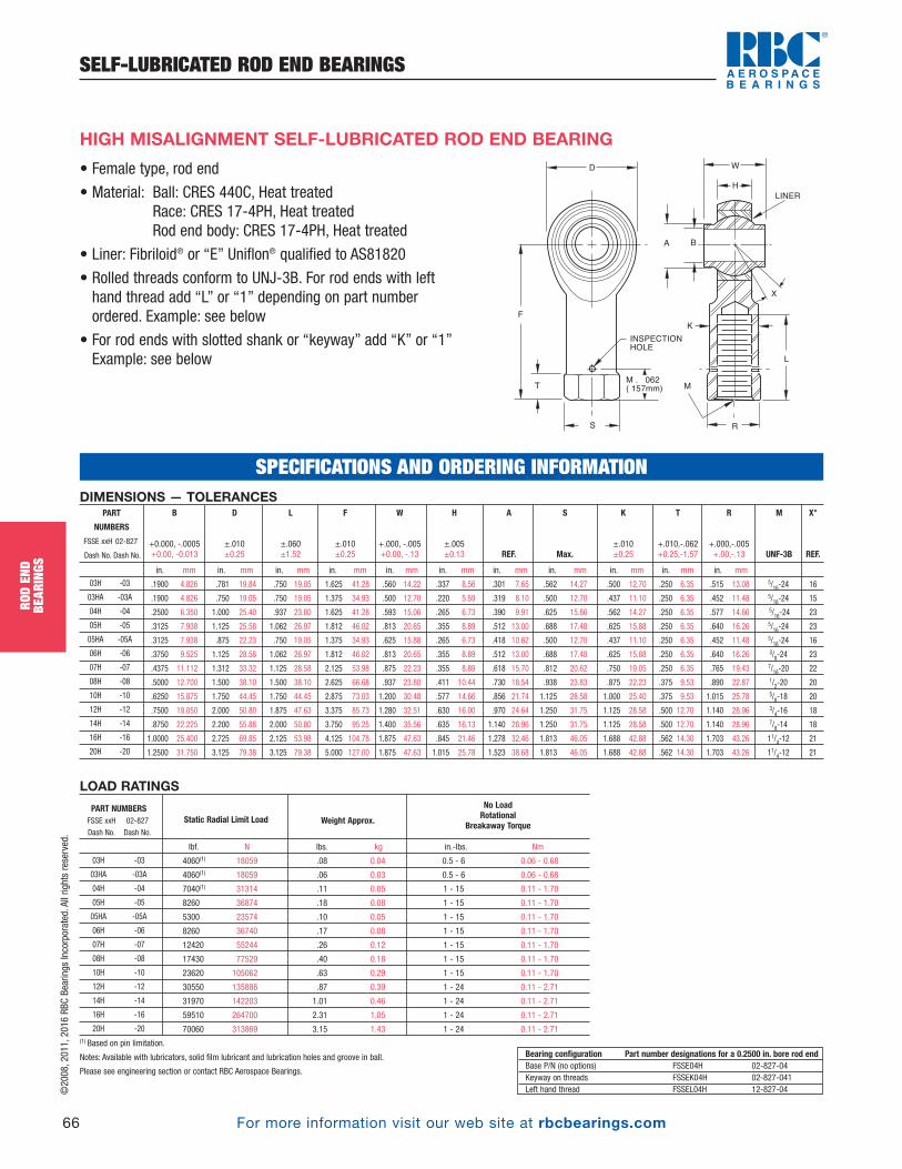
For more information visit our web site at rbcbearings.com
SELF-LUBRICATED ROD END BEARINGS
66
ROD
END
BEAR
INGS
©2008, 2011, 2016 RBC Bearings Incorporated. All rights reserved.
• Female type, rod end
• Material: Ball: CRES 440C, Heat treatedRace: CRES 17-4PH, Heat treatedRod end body: CRES 17-4PH, Heat treated
• Liner: Fibriloid® or “E” Uniflon® qualified to AS81820
• Rolled threads conform to UNJ-3B. For rod ends with lefthand thread add “L” or “1” depending on part numberordered. Example: see below
• For rod ends with slotted shank or “keyway” add “K” or “1” Example: see below
HIGH MISALIGNMENT SELF-LUBRICATED ROD END BEARING
LOAD RATINGS
lbf. N lbs. kg in.-lbs. Nm
4060(1) 18059 .08 0.04 0.5 - 6 0.06 - 0.68
4060(1) 18059 .06 0.03 0.5 - 6 0.06 - 0.68
7040(1) 31314 .11 0.05 1 - 15 0.11 - 1.70
8260 36874 .18 0.08 1 - 15 0.11 - 1.70
5300 23574 .10 0.05 1 - 15 0.11 - 1.70
8260 36740 .17 0.08 1 - 15 0.11 - 1.70
12420 55244 .26 0.12 1 - 15 0.11 - 1.70
17430 77529 .40 0.18 1 - 15 0.11 - 1.70
23620 105062 .63 0.29 1 - 15 0.11 - 1.70
30550 135886 .87 0.39 1 - 24 0.11 - 2.71
31970 142203 1.01 0.46 1 - 24 0.11 - 2.71
59510 264700 2.31 1.05 1 - 24 0.11 - 2.71
70060 313869 3.15 1.43 1 - 24 0.11 - 2.71(1) Based on pin limitation.
Notes: Available with lubricators, solid film lubricant and lubrication holes and groove in ball.
Please see engineering section or contact RBC Aerospace Bearings.
Static Radial Limit Load
No LoadRotational
Breakaway TorqueWeight Approx.PART NUMBERSFSSE xxH 02-827
Dash No. Dash No.
03H -03
03HA -03A
04H -04
05H -05
05HA -05A
06H -06
07H -07
08H -08
10H -10
12H -12
14H -14
16H -16
20H -20
Bearing configuration Part number designations for a 0.2500 in. bore rod endBase P/N (no options) FSSE04H 02-827-04Keyway on threads FSSEK04H 02-827-041Left hand thread FSSEL04H 12-827-04
DIMENSIONS — TOLERANCES
in. mm in. mm in. mm in. mm in. mm in. mm in. mm in. mm in. mm in. mm in. mm
.1900 4.826 .781 19.84 .750 19.05 1.625 41.28 .560 14.22 .337 8.56 .301 7.65 .562 14.27 .500 12.70 .250 6.35 .515 13.08 5/16-24 16
.1900 4.826 .750 19.05 .750 19.05 1.375 34.93 .500 12.70 .220 5.59 .319 8.10 .500 12.70 .437 11.10 .250 6.35 .452 11.48 5/16-24 15
.2500 6.350 1.000 25.40 .937 23.80 1.625 41.28 .593 15.06 .265 6.73 .390 9.91 .625 15.86 .562 14.27 .250 6.35 .577 14.66 5/16-24 23
.3125 7.938 1.125 25.58 1.062 26.97 1.812 46.02 .813 20.65 .355 8.89 .512 13.00 .688 17.48 .625 15.88 .250 6.35 .640 16.26 5/16-24 23
.3125 7.938 .875 22.23 .750 19.05 1.375 34.93 .625 15.88 .265 6.73 .418 10.62 .500 12.70 .437 11.10 .250 6.35 .452 11.48 5/16-24 16
.3750 9.525 1.125 28.58 1.062 26.97 1.812 46.02 .813 20.65 .355 8.89 .512 13.00 .688 17.48 .625 15.88 .250 6.35 .640 16.26 3/8-24 23
.4375 11.112 1.312 33.32 1.125 28.58 2.125 53.98 .875 22.23 .355 8.89 .618 15.70 .812 20.62 .750 19.05 .250 6.35 .765 19.43 7/16-20 22
.5000 12.700 1.500 38.10 1.500 38.10 2.625 66.68 .937 23.80 .411 10.44 .730 18.54 .938 23.83 .875 22.23 .375 9.53 .890 22.87 1/2-20 20
.6250 15.875 1.750 44.45 1.750 44.45 2.875 73.03 1.200 30.48 .577 14.66 .856 21.74 1.125 28.58 1.000 25.40 .375 9.53 1.015 25.78 5/8-18 20
.7500 19.050 2.000 50.80 1.875 47.63 3.375 85.73 1.280 32.51 .630 16.00 .970 24.64 1.250 31.75 1.125 28.58 .500 12.70 1.140 28.96 3/4-16 18
.8750 22.225 2.200 55.88 2.000 50.80 3.750 95.25 1.400 35.56 .635 16.13 1.140 28.96 1.250 31.75 1.125 28.58 .500 12.70 1.140 28.96 7/8-14 18
1.0000 25.400 2.725 69.85 2.125 53.98 4.125 104.78 1.875 47.63 .845 21.46 1.278 32.46 1.813 46.05 1.688 42.88 .562 14.30 1.703 43.26 11/4-12 21
1.2500 31.750 3.125 79.38 3.125 79.38 5.000 127.00 1.875 47.63 1.015 25.78 1.523 38.68 1.813 46.05 1.688 42.88 .562 14.30 1.703 43.26 11/4-12 21
R
+.000,-.005 +.00,-.13
T
+.010,-.062 +0.25,-1.57
K
±.010 ±0.25
S
Max.
X°
REF.
M
UNF-3B
A
REF.
H
±.005 ±0.13
W
+.000, -.005 +0.00, -.13
F
±.010 ±0.25
L
±.060 ±1.52
D
±.010±0.25
B
+0.000, -.0005 +0.00, -0.013
PART
NUMBERS
FSSE xxH 02-827
Dash No. Dash No.
03H -03
03HA -03A
04H -04
05H -05
05HA -05A
06H -06
07H -07
08H -08
10H -10
12H -12
14H -14
16H -16
20H -20
SPECIFICATIONS AND ORDERING INFORMATION
D
F
T
S
M . 062
( 157mm)
INSPECTION
HOLE
R
A
W
H
LINER
B
X
L
K
M
PB_049_072_8-29-16_Pln_051_078.qxd 8/30/16 11:05 AM Page 66

For more information visit our web site at rbcbearings.com
METAL-TO-METAL ROD END BEARINGS
67
ROD
END
BEAR
INGS
©2008, 2011, 2016 RBC Bearings Incorporated. All rights reserved.
DIMENSIONS — TOLERANCES
in. mm in. mm in. mm in. mm in. mm in. mm in. mm
.1900 4.826 .781 19.84 1.000 25.40 1.562 39.67 .560 14.22 .337 8.56 .301 7.65 5/16-24 16
.1900 4.826 .750 19.05 1.000 25.40 1.500 38.10 .500 12.70 .220 5.59 .319 8.10 5/16-24 15
.2500 6.350 1.000 25.40 1.250 31.75 1.938 49.23 .593 15.06 .265 6.73 .390 9.91 5/16-24 23
.3125 7.938 1.125 25.58 1.375 34.93 2.125 53.98 .813 20.65 .355 8.89 .512 13.00 5/16-24 23
.3125 7.938 .875 22.23 1.062 26.97 1.875 47.63 .625 15.88 .265 6.73 .418 10.62 5/16-24 16
.3750 9.525 1.125 28.58 1.375 34.93 2.125 53.98 .813 20.65 .355 8.89 .512 13.00 3/8-24 23
.4375 11.112 1.312 33.32 1.500 38.10 2.437 61.90 .875 22.23 .355 8.89 .618 15.70 7/16-20 22
.5000 12.700 1.500 38.10 1.625 41.28 2.625 66.68 .937 23.80 .411 10.44 .730 18.54 1/2-20 20
.6250 15.875 1.750 44.45 1.750 44.45 2.875 73.03 1.200 30.48 .577 14.66 .856 21.74 5/8-18 20
.7500 19.050 2.000 50.80 1.875 47.63 3.375 85.73 1.280 32.51 .630 16.00 .970 24.64 3/4-16 18
.8750 22.225 2.200 55.88 2.000 50.80 3.750 95.25 1.400 35.56 .635 16.13 1.140 28.96 7/8-14 18
1.0000 25.400 2.725 69.85 2.125 53.98 4.125 104.78 1.875 47.63 .845 21.46 1.278 32.46 11/4-12 21
1.2500 31.750 3.125 79.38 2.875 73.03 5.000 127.00 1.875 47.63 1.015 25.78 1.523 38.68 11/4-12 21
X°
REF.
M
UNF-3A
A
REF.
H
±.005 ±0.13
W
+.000, -.005 +0.00, -.13
F
±.010 ±0.25
L
±.060 ±1.52
D
±.010±0.25
B
+.0000, -.0005 +0.00, -0.013
PART
NUMBERS
MSS xxH 01-507
Dash No. Dash No.
03H -03
03HA -03A
04H -04
05H -05
05HA -05A
06H -06
07H -07
08H -08
10H -10
12H -12
14H -14
16H -16
20H -20
SPECIFICATIONS AND ORDERING INFORMATION
• Male type, rod end
• Material: Ball: CRES 440C, Heat treatedRace: CRES 17-4PH, Heat treatedRod end body: CRES 17-4PH, Heat treated
• Rolled threads conform to UNJ-3A. For rod ends with lefthand thread add “L” or “1” depending on part numberordered. Example: see below
• For rod ends with slotted shank or “keyway” add “K” or “1” Example: see below
HIGH MISALIGNMENT METAL-TO-METAL ROD END BEARING
LOAD RATINGS
lbf. N lbs. kg in. mm
4060(1) 18059 .08 0.04 .002 0.05
4060(1) 18059 .06 0.03 .002 0.05
7040(1) 31314 .11 0.05 .002 0.05
8260 36874 .18 0.08 .002 0.05
5300 23574 .10 0.05 .002 0.05
8260 36740 .17 0.08 .002 0.05
12420 55244 .26 0.12 .002 0.05
17430 77529 .40 0.18 .002 0.05
23620 105062 .63 0.29 .002 0.05
30550 135886 .87 0.39 .002 0.05
31970 142203 1.01 0.46 .002 0.05
59510 264700 2.31 1.05 .002 0.05
70060 313869 3.15 1.43 .002 0.05(1) Based on pin limitation.
Notes: Available with lubricators, solid film lubricant and lubrication holes and groove in ball.
Please see engineering section or contact RBC Aerospace Bearings.
Static Radial Limit Load Maximum Radial ClearanceWeight Approx.PART NUMBERSMSS xxH 01-507
Dash No. Dash No.
03H -03
03HA -03A
04H -04
05H -05
05HA 05A
06H -06
07H -07
08H -08
10H -10
12H -12
14H -14
16H -16
20H -20
Bearing configuration Part number designations for a 0.2500 in. bore rod endBase P/N (no options) MSS04H 01-507-04Keyway on threads MSSK04H 01-507-041Left hand thread MSSL04H 11-507-04
F
M
A B
X
DW
H
L
LubricatorOptional
PB_049_072_8-29-16_Pln_051_078.qxd 8/30/16 11:05 AM Page 67

For more information visit our web site at rbcbearings.com
METAL-TO-METAL ROD END BEARINGS
68
ROD
END
BEAR
INGS
©2008, 2011, 2016 RBC Bearings Incorporated. All rights reserved.
• Female type, rod end
• Material: Ball: CRES 440C, Heat treatedRace: CRES 17-4PH, Heat treatedRod end body: CRES 17-4PH, Heat treated
• Rolled threads conform to UNJ-3B. For rod ends with lefthand thread add “L” or “1” depending on part numberordered. Example: see below
• For rod ends with slotted shank or “keyway” add “K” or “1” Example: see below
HIGH MISALIGNMENT METAL-TO-METAL ROD END BEARING
LOAD RATINGS
lbf. N lbs. kg in. mm
4060(1) 18059 .08 0.04 .002 0.05
4060(1) 18059 .06 0.03 .002 0.05
7040(1) 31314 .11 0.05 .002 0.05
8260 36874 .18 0.08 .002 0.05
5300 23574 .10 0.05 .002 0.05
8260 36740 .17 0.08 .002 0.05
12420 55244 .26 0.12 .002 0.05
17430 77529 .40 0.18 .002 0.05
23620 105062 .63 0.29 .002 0.05
30550 135886 .87 0.39 .002 0.05
31970 142203 1.01 0.46 .002 0.05
59510 264700 2.31 1.05 .002 0.05
70060 313869 3.15 1.43 .002 0.05(1) Based on pin limitation.
Notes: Available with lubricators, solid film lubricant and lubrication holes and groove in ball.
Please see engineering section or contact RBC Aerospace Bearings.
Static Radial Limit Load
No LoadRotational
Breakaway TorqueWeight Approx.PART NUMBERSFSS xxH 02-507
Dash No. Dash No.
03H -03
03HA -03A
04H -04
05H -05
05HA -05A
06H -06
07H -07
08H -08
10H -10
12H -12
14H -14
16H -16
20H -20
Bearing configuration Part number designations for a 0.2500 in. bore rod endBase P/N (no options) FSS04H 02-507-04Keyway on threads FSSK04H 02-507-041Left hand thread FSSL04H 12-507-04
DIMENSIONS — TOLERANCES
in. mm in. mm in. mm in. mm in. mm in. mm in. mm in. mm in. mm in. mm in. mm
.1900 4.826 .781 19.84 .750 19.05 1.625 41.28 .560 14.22 .337 8.56 .301 7.65 .562 14.27 .500 12.70 .250 6.35 .515 13.08 5/16-24 16
.1900 4.826 .750 19.05 .750 19.05 1.375 34.93 .500 12.70 .220 5.59 .319 8.10 .500 12.70 .437 11.10 .250 6.35 .452 11.48 5/16-24 15
.2500 6.350 1.000 25.40 .937 23.80 1.625 41.28 .593 15.06 .265 6.73 .390 9.91 .625 15.86 .562 14.27 .250 6.35 .577 14.66 5/16-24 23
.3125 7.938 1.125 25.58 1.062 26.97 1.812 46.02 .813 20.65 .355 8.89 .512 13.00 .688 17.48 .625 15.88 .250 6.35 .640 16.26 5/16-24 23
.3125 7.938 .875 22.23 .750 19.05 1.375 34.93 .625 15.88 .265 6.73 .418 10.62 .500 12.70 .437 11.10 .250 6.35 .452 11.48 5/16-24 16
.3750 9.525 1.125 28.58 1.062 26.97 1.812 46.02 .813 20.65 .355 8.89 .512 13.00 .688 17.48 .625 15.88 .250 6.35 .640 16.26 3/8-24 23
.4375 11.112 1.312 33.32 1.125 28.58 2.125 53.98 .875 22.23 .355 8.89 .618 15.70 .812 20.62 .750 19.05 .250 6.35 .765 19.43 7/16-20 22
.5000 12.700 1.500 38.10 1.500 38.10 2.625 66.68 .937 23.80 .411 10.44 .730 18.54 .938 23.83 .875 22.23 .375 9.53 .890 22.87 1/2-20 20
.6250 15.875 1.750 44.45 1.750 44.45 2.875 73.03 1.200 30.48 .577 14.66 .856 21.74 1.125 28.58 1.000 25.40 .375 9.53 1.015 25.78 5/8-18 20
.7500 19.050 2.000 50.80 1.875 47.63 3.375 85.73 1.280 32.51 .630 16.00 .970 24.64 1.250 31.75 1.125 28.58 .500 12.70 1.140 28.96 3/4-16 18
.8750 22.225 2.200 55.88 2.000 50.80 3.750 95.25 1.400 35.56 .635 16.13 1.140 28.96 1.250 31.75 1.125 28.58 .500 12.70 1.140 28.96 7/8-14 18
1.0000 25.400 2.725 69.85 2.125 53.98 4.125 104.78 1.875 47.63 .845 21.46 1.278 32.46 1.813 46.05 1.688 42.88 .562 14.30 1.703 43.26 11/4-12 21
1.2500 31.750 3.125 79.38 3.125 79.38 5.000 127.00 1.875 47.63 1.015 25.78 1.523 38.68 1.813 46.05 1.688 42.88 .562 14.30 1.703 43.26 11/4-12 21
X°
REF.
M
UNF-3B
R
+.000,-.005 +.00,-.13
T
+.010,-.062 +0.25,-1.57
K
±.010 ±0.25
S
Max.
A
REF.
H
±.005 ±0.13
W
+.000, -.005 +0.00, -.13
F
±.010 ±0.25
L
±.060 ±1.52
D
±.010±0.25
B
+0.000, -.0005 +0.00, -0.013
PART
NUMBERS
FSS xxH 02-507
Dash No. Dash No.
03H -03
03HA -03
04H -04
05H -05
05HA -05
06H -06
07H -07
08H -08
10H -10
12H -12
14H -14
16H -16
20H -20
SPECIFICATIONS AND ORDERING INFORMATION
D
F
T
S
M . 062
( 157mm)
INSPECTION
HOLE
R
A
W
H
B
X
L
K
M
PB_049_072_8-29-16_Pln_051_078.qxd 8/30/16 11:05 AM Page 68

For more information visit our web site at rbcbearings.com
SELF-LUBRICATED ROD END BEARINGS
69
ROD
END
BEAR
INGS
©2008, 2011, 2016 RBC Bearings Incorporated. All rights reserved.
F
015 (0.38mm)
005 (0.13mm)
L G
P
M
K
R
A B J
LINER
X
DW
H
HIGH TEMPERATURE SELF-LUBRICATED ROD END BEARING
DIMENSIONS — TOLERANCES
in. mm in. mm in. mm in. mm in. mm in. mm in. mm in. mm in. mm in. mm in. mm
.1900 4.826 .806 20.47 .968 24.59 1.562 39.67 .437 11.10 .337 8.56 .30 7.6 .6250 15.875 .980 24.89 .062 1.57 .268 6.81 5/16-24 15
.2500 6.350 .806 20.47 .968 24.59 1.562 39.67 .437 11.10 .337 8.56 .30 7.6 .6250 15.875 .980 24.89 .062 1.57 .268 6.81 5/16-24 15
.3125 7.938 .900 22.86 1.187 30.15 1.875 47.62 .437 11.10 .327 8.31 .36 9.1 .6875 17.462 1.270 32.26 .062 1.57 .268 6.81 5/16-24 14
.3750 9.525 1.025 26.04 1.187 30.15 1.938 49.23 .500 12.70 .416 10.57 .47 11.9 .8125 20.638 1.235 31.37 .093 2.36 .319 8.10 3/8-24 8
.4375 11.112 1.150 29.21 1.281 32.54 2.125 53.98 .562 14.27 .452 11.48 .54 13.7 .9062 23.017 1.402 35.61 .093 2.36 .383 9.73 7/16-20 10
.5000 12.700 1.337 33.96 1.468 37.29 2.438 61.93 .625 15.88 .515 13.08 .61 15.5 1.0000 25.400 1.589 40.36 .093 2.36 .445 11.30 1/2-20 9
.6250 15.875 1.525 38.74 1.562 39.67 2.625 66.68 .750 19.05 .577 14.66 .75 19.1 1.1875 30.162 1.683 42.75 .125 3.18 .541 13.74 5/8-18 12
.7500 19.050 1.775 45.08 1.687 42.85 2.875 73.02 .875 22.22 .640 16.26 .85 21.6 1.3750 34.925 1.808 45.92 .125 3.18 .663 16.84 3/4-16 13
.8750 22.225 2.025 51.44 2.000 50.80 3.375 85.72 .875 22.22 .765 19.43 1.061 26.95 1.6250 41.275 2.121 53.87 .156 3.96 .777 19.74 7/8-14 6
1.0000 25.400 2.775 70.48 2.343 59.51 4.125 104.78 1.375 34.92 1.015 25.78 1.27 32.3 2.1250 53.975 2.464 62.59 .187 4.75 1.136 28.85 11/4-12 12(1)Keyway when specified, is compatible with locking devices, AS81935/3 for sizes 3 thru 8, and NAS559 for sizes 10 thru 16.
Keyway tolerances not specified shall be in accordance with AS81935/3 or NAS513 as applicable.
P(1)
+.000,-.005 +.00,-.13
K(1)
+.005,-.000 +.13,-.00
G)
+.000,-.020 +.00,-.51
J
Max.
X°
Min.
M
UNJF-3APER
AS8879
A
Min.
H
±.005 ±.13
W
+.000,-.002 +.00,-.05
F
±.010 ±.25
L
±.031 ±.79
D
±.010±.25
B
+0.000,-.0005 +0.00,-.013
PART NUMBER
01-450-03
01-450-04
01-450-05
01-450-06
01-450-07
01-450-08
01-450-10
01-450-12
01-450-14
01-450-16
LOAD RATINGS
lbf. N lbf. N lbf. N lbs. kg in.-lbs. Nm in.-lbs. Nm
2360 10400 1470(1) 6550(2) 1000 4400 0.042 0.019 .5 .06 6 .68
4860 21600 2380 10600 1000 4400 0.042 0.019 .5 .06 6 .68
7180 32000 277O(3) 12200(3) 1100 4900 0.050 0.023 .5 .06 6 .68
8550 38000 3570 16000 1660 7350 0.079 0.035 1 .11 15 1.70
12000 53000 4800 21200 1850 8300 0.106 0.048 1 .11 15 1.70
19500 86500 7680(3) 34000(3) 2040 9000 0.161 0.072 1 .11 15 1.70
21900 98000 9180 40500 2430 10800 0.245 0.110 1 .11 15 1.70
29300 129000 11600 52000 2810 12500 0.369 0.166 1 .11 15 1.70
34500 153000 13100 58500 3320 14600 0.557 0.250 1 .11 24 2.71
80300 355000 30400 134000 4340 19300 1.472 0.662 1 .11 24 2.71
UltimateStaticLoad
No LoadRotational
Breakaway TorqueMin. Max.
Weight
Max.
AxialProofLoad
Fatigue
Load
PART
NUMBER
01-450-03
01-450-04
01-450-05
01-450-06
01-450-07
01-450-08
01-450-10
01-450-12
01-450-14
01-450-16
Bearing configuration Part number designations for a 0.2500 in. bore rod endBase P/N (no options) 01-450-04Keyway on threads 01-450-041Left hand thread 11-450-04
Please contact the RBC Engineering Support Team for specific load information or to
customize a high temperature product for your particular needs.
SPECIFICATIONS AND ORDERING INFORMATION
• Male type, rod end
• High temperature — low wear -65°F to +600°F (-53.9°C to +301°C)
• MaterialBearing inner ring: Cobalt Base Alloy with proprietary coatingBearing outer ring: A-286 raceRod end housing: CRES 17-4PH
• Liner: Fabroid® X
• Rolled threads conform to UNJF-3A per AS8879For rod ends with left hand thread add “1”Example: 11-450-06
• For rod ends with slotted shank or “keyway” add “1”Example: 01-450-061
• For both keyway and left hand thread, combine options asshown below. Example: 11-450-061
PB_049_072_8-29-16_Pln_051_078.qxd 8/30/16 11:05 AM Page 69
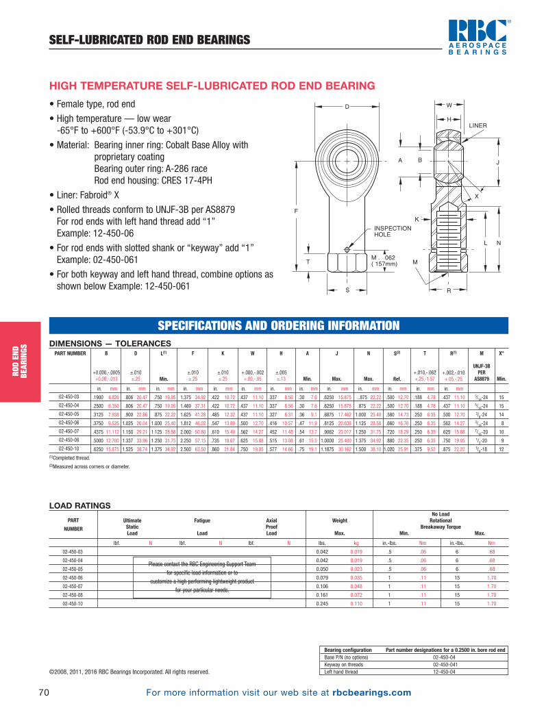
For more information visit our web site at rbcbearings.com
SELF-LUBRICATED ROD END BEARINGS
70
ROD
END
BEAR
INGS
HIGH TEMPERATURE SELF-LUBRICATED ROD END BEARING
DIMENSIONS — TOLERANCES
in. mm in. mm in. mm in. mm in. mm in. mm in. mm in. mm in. mm in. mm in. mm in. mm in. mm
.1900 4.826 .806 20.47 .750 19.05 1.375 34.92 .422 10.72 .437 11.10 .337 8.56 .30 7.6 .6250 15.875 ..875 22.22 .500 12.70 .188 4.78 .437 11.10 5/16-24 15
.2500 6.350 .806 20.47 .750 19.05 1.469 37.31 .422 10.72 .437 11.10 .337 8.56 .30 7.6 .6250 15.875 .875 22.22 .500 12.70 .188 4.78 .437 11.10 5/16-24 15
.3125 7.938 .900 22.86 .875 22.22 1.625 41.28 .485 12.32 .437 11.10 .327 8.31 .36 9.1 .6875 17.462 1.000 25.40 .580 14.73 .250 6.35 .500 12.70 3/8-24 14
.3750 9.525 1.025 26.04 1.000 25.40 1.812 46.02 .547 13.89 .500 12.70 .416 10.57 .47 11.9 .8125 20.638 1.125 28.58 .660 16.76 .250 6.35 .562 14.27 3/18-24 8
.4375 11.112 1.150 29.21 1.125 28.58 2.000 50.80 .610 15.49 .562 14.27 .452 11.48 .54 13.7 .9062 23.017 1.250 31.75 .720 18.29 .250 6.35 .625 15.88 7/16-20 10
.5000 12.700 1.337 33.96 1.250 31.75 2.250 57.15 .735 18.67 .625 15.88 .515 13.08 .61 15.5 1.0000 25.400 1.375 34.92 .880 22.35 .250 6.35 .750 19.05 1/2-20 9
.6250 15.875 1.525 38.74 1.375 34.92 2.500 63.50 .860 21.84 .750 19.05 .577 14.66 .75 19.1 1.1875 30.162 1.500 38.10 1.020 25.91 .375 9.52 .875 22.22 5/8-18 12(1)Completed thread. (2)Measured across corners or diameter.
S(2)
Ref.
N
Max.
J
Max.
A
Min.
K
±.010 ±.25
F
±.010 ±.25
R(1)
+.002,-.010 +.05,-.25
T
+.010,-.062 +.25,-1.57
X°
Min.
M
UNJF-3BPER
AS8879
H
±.005 ±.13
W
+.000,-.002 +.00,-.05
L(1)
Min.
D
±.010±.25
B
+0.000,-.0005 +0.00,-.013
PART NUMBER
02-450-03
02-450-04
02-450-05
02-450-06
02-450-07
02-450-08
02-450-10
LOAD RATINGS
lbf. N lbf. N lbf. N lbs. kg in.-lbs. Nm in.-lbs. Nm
2360 10400 1470(1) 6550(2) 1000 4400 0.042 0.019 .5 .06 6 .68
4860 21600 2380 10600 1000 4400 0.042 0.019 .5 .06 6 .68
7180 32000 277O(3) 12200(3) 1100 4900 0.050 0.023 .5 .06 6 .68
8550 38000 3570 16000 1660 7350 0.079 0.035 1 .11 15 1.70
12000 53000 4800 21200 1850 8300 0.106 0.048 1 .11 15 1.70
19500 86500 7680(3) 34000(3) 2040 9000 0.161 0.072 1 .11 15 1.70
21900 98000 9180 40500 2430 10800 0.245 0.110 1 .11 15 1.70
UltimateStaticLoad
No LoadRotational
Breakaway TorqueMin. Max.
Weight
Max.
AxialProofLoad
Fatigue
Load
PART
NUMBER
02-450-03
02-450-04
02-450-05
02-450-06
02-450-07
02-450-08
02-450-10
Bearing configuration Part number designations for a 0.2500 in. bore rod endBase P/N (no options) 02-450-04Keyway on threads 02-450-041Left hand thread 12-450-04
SPECIFICATIONS AND ORDERING INFORMATION
D
F
T
S
M . 062
( 157mm)
INSPECTION
HOLE
R
A
W
H
LINER
B
X
L N
K
M
J
©2008, 2011, 2016 RBC Bearings Incorporated. All rights reserved.
• Female type, rod end
• High temperature — low wear -65°F to +600°F (-53.9°C to +301°C)
• Material: Bearing inner ring: Cobalt Base Alloy withproprietary coatingBearing outer ring: A-286 raceRod end housing: CRES 17-4PH
• Liner: Fabroid® X
• Rolled threads conform to UNJF-3B per AS8879For rod ends with left hand thread add “1”Example: 12-450-06
• For rod ends with slotted shank or “keyway” add “1”Example: 02-450-061
• For both keyway and left hand thread, combine options asshown below Example: 12-450-061
Please contact the RBC Engineering Support Team for specific load information or to
customize a high performing lightweight product for your particular needs.
PB_049_072_8-29-16_Pln_051_078.qxd 8/30/16 11:05 AM Page 70
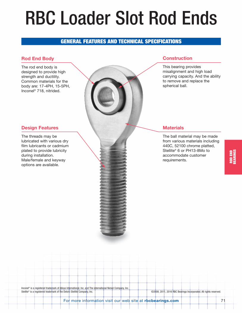
For more information visit our web site at rbcbearings.com 71
ROD
END
BEAR
INGS
RBC Loader Slot Rod EndsGENERAL FEATURES AND TECHNICAL SPECIFICATIONS
Rod End Body
The rod end body isdesigned to provide highstrength and ductility.Common materials for thebody are: 17-4PH, 15-5PH,Inconel® 718, nitrided.
Materials
The ball material may be madefrom various materials including440C, 52100 chrome platted,Stellite® 6 or PH13-8Mo toaccommodate customerrequirements.
Construction
This bearing providesmisalignment and high loadcarrying capacity. And the abilityto remove and replace thespherical ball.
Design Features
The threads may belubricated with various dryfilm lubricants or cadmiumplated to provide lubricityduring installation.Male/female and keywayoptions are available.
Inconel® is a registered trademark of Alloys International, Inc. and The international Nickel Company, Inc.Stellite® is a registered trademark of the Deloro Stellite Company, Inc. ©2008, 2011, 2016 RBC Bearings Incorporated. All rights reserved.
PB_049_072_8-29-16_Pln_051_078.qxd 8/30/16 11:05 AM Page 71
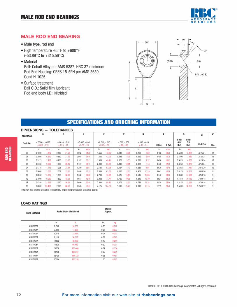
For more information visit our web site at rbcbearings.com
MALE ROD END BEARINGS
72
ROD
END
BEAR
INGS
©2008, 2011, 2016 RBC Bearings Incorporated. All rights reserved.
For more information visit our web site at rbcbearings.com
• Male type, rod end
• High temperature -65°F to +600°F(-53.89°C to +315.56°C)
• MaterialBall: Cobalt Alloy per AMS 5387, HRC 37 minimumRod End Housing: CRES 15-5PH per AMS 5659Cond H-1025
• Surface treatmentBall O.D.: Solid film lubricantRod end body I.D.: Nitrided
MALE ROD END BEARING
F
L
M
Ø D
(Ø D) Ø B
BALL (Ø S)
W
X°
H
DIMENSIONS — TOLERANCES
in. mm in. mm in. mm in. mm in. mm in. mm in. mm in. mm
03 0.1900 4.826 0.850 21.59 0.968 24.59 1.656 42.06 0.343 8.71 0.260 6.60 0.405 10.29 0.5300 13.462 .3125-24 12
04 0.2500 6.350 0.850 21.59 0.968 24.59 1.656 42.06 0.343 8.71 0.260 6.60 0.405 10.29 0.5300 13.462 .3125-24 12
05 0.3125 7.938 0.900 22.86 1.187 30.15 1.906 48.41 0.375 9.53 0.290 7.37 0.420 10.67 0.5625 14.288 .3125-24 12
06 0.3750 9.525 1.000 25.40 1.187 30.15 2.000 50.80 0.406 10.31 0.322 8.18 0.476 12.09 0.6250 15.875 .3750-24 11
07 0.4375 11.113 1.095 27.81 1.280 32.51 2.125 53.98 0.437 11.10 0.353 8.97 0.530 13.46 0.6865 17.437 .4375-20 10
08 0.5000 12.700 1.332 33.83 1.468 37.29 2.560 65.02 0.500 12.70 0.405 10.29 0.641 16.28 0.8125 20.638 .5000-20 9
10 0.6250 15.875 1.535 38.99 1.560 39.62 2.780 70.61 0.625 15.88 0.515 13.08 0.740 18.80 0.9680 24.587 .6250-18 9
12 0.7500 19.050 1.890 48.01 1.687 42.85 3.062 77.77 0.750 19.05 0.610 15.49 0.921 23.39 1.1870 30.150 .7500-18 9
14 0.8750 22.225 2.210 56.13 2.000 50.80 3.560 90.42 0.875 22.23 0.718 18.24 0.978 24.84 1.3120 33.325 .8750-14 9
16 1.0000 25.400 2.625 66.68 2.343 59.51 4.125 104.78 1.000 25.40 0.817 20.75 1.119 28.42 1.5000 38.100 1.2500-12 9
.002 inch max internal clearance (contact RBC engineering for reduced clearance design)
M
UNJF-3A
W
+.000, -.002 +.00, -.05
F
+0.010, -.010+0.25, -.25
MSSTMxxA
Dash No.
S
Ø Ball Ø BallO.D. O.D.Ref. Ref.
X°
Min.
A
Ø Ref. Ø Ref.
H
+.000, -.020 +.00, -.51
L
+0.030, -.030 +0.76, -.76
D
+0.010, -.010 +0.25, -.25
B
+.0000, - .0005 +.000, -.013
SPECIFICATIONS AND ORDERING INFORMATION
LOAD RATINGS
lbf. N lbs. kg
MSSTM03A 2,256 10,035 0.06 0.027
MSSTM04A 3,904 17,366 0.06 0.027
MSSTM05A 5,273 23,454 0.07 0.032
MSSTM06A 8,113 36,088 0.09 0.041
MSSTM07A 10,962 48,763 0.12 0.054
MSSTM08A 14,930 66,412 0.20 0.091
MSSTM10A 23,256 103,448 0.34 0.154
MSSTM12A 28,168 125,297 0.62 0.281
MSSTM14A 32,400 144,122 0.95 0.431
MSSTM16A 37,264 165,758 1.50 0.680
WeightApprox.Radial Static Limit LoadPART NUMBER
PB_049_072_8-29-16_Pln_051_078.qxd 8/30/16 11:05 AM Page 72

©2008, 2011, 2016 RBC Bearings Incorporated. All rights reserved.
For more information visit our web site at rbcbearings.com 73
JOUR
NAL
BEAR
INGS
SELF-LUBRICATINGAS81934 Plain SeriesM81934/1 Aluminum, Self-Lubricated,
Plain Journal Series . . . . . . . . . . . . . . . . . . . . . . . . . . . 74M81934/1 CRES, Self-Lubricated,
Plain Journal Series . . . . . . . . . . . . . . . . . . . . . . . . . . . 75AS81934 Flanged SeriesM81934/2 Aluminum, Self-Lubricated,
Flanged Journal Series. . . . . . . . . . . . . . . . . . . . . . . . . 76M81934/2 CRES, Self-Lubricated,
Flanged Journal Series. . . . . . . . . . . . . . . . . . . . . . . . . 77EN Standard SeriesEN2285 Aluminum, Self-Lubricated,
Straight Journal Series . . . . . . . . . . . . . . . . . . . . . . . . . 78EN2286 Aluminum, Self-Lubricated,
Flanged Journal Series. . . . . . . . . . . . . . . . . . . . . . . . . 79EN2287 CRES, Self-Lubricated, Straight Journal Series . . . . . . . 80EN2288 CRES, Self-Lubricated, Flanged Journal Series. . . . . . . 81High Temperature Plain/Flanged SeriesHigh Temperature, Self-Lubricated, Straight Journal Series . . . . . . . . . 82High Temperature, Self-Lubricated, Flanged Journal Series . . . . . . . . . 83
UNIFLON® HP Machinable Liner per AS81934AS81934 Plain SeriesM81934/1 Aluminum, Machinable Liner, Plain Journal Series . . . . 84M81934/1 CRES, Machinable Liner, Plain Journal Series . . . . . . . . 85AS81934 Flanged SeriesM81934/2 Aluminum, Machinable Liner, Flanged Journal Series . . 86M81934/2 CRES, Machinable Liner, Flanged Journal Series . . . . . 87Dyflon® Water Resistant Plain/Flanged SeriesDyflon®, Self-Lubricated, Straight Journal Series . . . . . . . . . . . . . . . . . 88Dyflon®, Self-Lubricated, Flanged Journal Series . . . . . . . . . . . . . . . . . 89Standard Bushing Feature Page . . . . . . . . . . . . . . . . . . . . . . . . . . . . 90Unlined BushingsNAS Plain/Flanged SeriesNAS76 Unlined, Aluminum Bronze, Plain Bushing Series . . . . . 91NAS77 Unlined, Aluminum Bronze, Flanged Bushing Series . . . 92MS Plain/Flanged SeriesMS14237 Unlined, Aluminum Bronze, Plain Bushing Series . . . . . 93MS14238 Unlined, Aluminum Bronze, Flanged Bushing Series . . . 94Special Bushings Feature Page. . . . . . . . . . . . . . . . . . . . . . . . . . . . . 95Links and Assemblies Feature Page . . . . . . . . . . . . . . . . . . . . . . . . 96
RBC Journal Bearings
GENERAL FEATURES AND TECHNICAL SPECIFICATIONS
Liner System
Bushings series areequipped with a self-lubricating liner systemto reduce friction andextend operating life.
Materials
Typical bushing materials are 17-4PH and aluminum.Bearings may also be cadmiumor zinc nickel plated as required.440C and Inconel 718 areavailable as required.
Design Features
Light weight and of compactdesign, this bearing areavailable in various bores of 1/16 in. and lengths of 1/32 in. increments.
Construction
A bushing is designedin a straight (or plain)configuration or with aflange to accommodatea combination of radialand axial load.
PB_073_097_8-30-16_Pln_079_103.qxd 8/30/16 11:08 AM Page 73
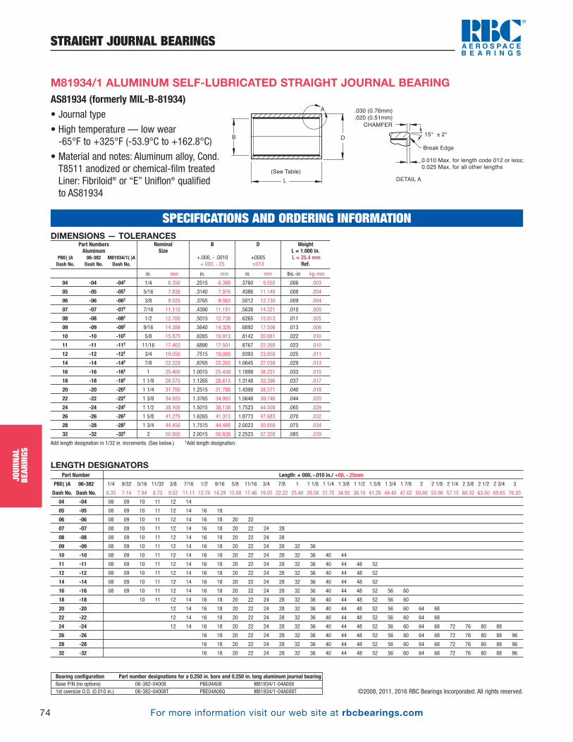
For more information visit our web site at rbcbearings.com
STRAIGHT JOURNAL BEARINGS
74
JOUR
NAL
BEAR
INGS
©2008, 2011, 2016 RBC Bearings Incorporated. All rights reserved.
DIMENSIONS — TOLERANCES
in. mm in. mm in. mm lbs.-in kg-mm
04 -04 -04† 1/4 6.350 .2515 6.388 .3760 9.550 .006 .003
05 -05 -05† 5/16 7.938 .3140 7.976 .4386 11.140 .008 .004
06 -06 -06† 3/8 9.525 .3765 9.563 .5012 12.730 .009 .004
07 -07 -07† 7/16 11.112 .4390 11.151 .5638 14.321 .010 .005
08 -08 -08† 1/2 12.700 .5015 12.738 .6265 15.913 .011 .005
09 -09 -09† 9/16 14.288 .5640 14.326 .6892 17.506 .013 .006
10 -10 -10† 5/8 15.875 .6265 15.913 .8142 20.681 .022 .010
11 -11 -11† 11/16 17.462 .6890 17.501 .8767 22.268 .023 .010
12 -12 -12† 3/4 19.050 .7515 19.088 .9393 23.858 .025 .011
14 -14 -14† 7/8 22.225 .8765 22.263 1.0645 27.038 .029 .013
16 -16 -16† 1 25.400 1.0015 25.438 1.1898 38.221 .033 .015
18 -18 -18† 1 1/8 28.575 1.1265 28.613 1.3148 33.396 .037 .017
20 -20 -20† 1 1/4 31.750 1.2515 31.788 1.4398 38.571 .040 .018
22 -22 -22† 1 3/8 34.925 1.3765 34.963 1.5648 39.746 .044 .020
24 -24 -24† 1 1/2 38.100 1.5015 38.138 1.7523 44.508 .065 .029
26 -26 -26† 1 5/8 41.275 1.6265 41.313 1.8773 47.683 .070 .032
28 -28 -28† 1 3/4 44.450 1.7515 44.488 2.0023 50.858 .075 .034
32 -32 -32† 2 50.800 2.0015 50.838 2.2523 57.208 .085 .039
Add length designation in 1/32 in. increments. (See below.) †Add length designation.
Weight L = 1.000 in.L = 25.4 mm
Ref.
D
±0005±013
B
+.000, - .0010 +.000, -.25
NominalSize
Part NumbersAluminum
PBE( )A 06-382 M81934/1( )ADash No. Dash No. Dash No.
AS81934 (formerly MIL-B-81934)• Journal type
• High temperature — low wear -65°F to +325°F (-53.9°C to +162.8°C)
• Material and notes: Aluminum alloy, Cond.T8511 anodized or chemical-film treatedLiner: Fibriloid® or “E” Uniflon® qualifiedto AS81934
B D
L
(See Table)
.030 (0.76mm)
.020 (0.51mm)
Break Edge
15° ± 2°
0.010 Max. for length code 012 or less; 0.025 Max. for all other lengths
CHAMFER
DETAIL A
A
M81934/1 ALUMINUM SELF-LUBRICATED STRAIGHT JOURNAL BEARING
LENGTH DESIGNATORSPart Number Length: + 000, -.010 in./ +00, -.25mm
PBE( )A 06-382 1/4 9/32 5/16 11/32 3/8 7/16 1/2 9/16 5/8 11/16 3/4 7/8 1 1 1/8 1 1/4 1 3/8 1 1/2 1 5/8 1 3/4 1 7/8 2 2 1/8 2 1/4 2 3/8 2 1/2 2 3/4 3
Dash No. Dash No. 6.35 7.14 7.94 8.73 9.52 11.11 12.70 14.29 15.88 17.46 19.05 22.22 25.40 28.58 31.75 34.92 38.10 41.28 44.45 47.62 50.80 53.98 57.15 60.32 63.50 69.85 76.20
04 -04 08 09 10 11 12 14
05 -05 08 09 10 11 12 14 16 18
06 -06 08 09 10 11 12 14 16 18 20 22
07 -07 08 09 10 11 12 14 16 18 20 22 24 28
08 -08 08 09 10 11 12 14 16 18 20 22 24 28
09 -09 08 09 10 11 12 14 16 18 20 22 24 28 32 36
10 -10 08 09 10 11 12 14 16 18 20 22 24 28 32 36 40 44
11 -11 08 09 10 11 12 14 16 18 20 22 24 28 32 36 40 44 48 52
12 -12 08 09 10 11 12 14 16 18 20 22 24 28 32 36 40 44 48 52
14 -14 08 09 10 11 12 14 16 18 20 22 24 28 32 36 40 44 48 52
16 -16 08 09 10 11 12 14 16 18 20 22 24 28 32 36 40 44 48 52 56 60
18 -18 10 11 12 14 16 18 20 22 24 28 32 36 40 44 48 52 56 60
20 -20 12 14 16 18 20 22 24 28 32 36 40 44 48 52 56 60 64 68
22 -22 12 14 16 18 20 22 24 28 32 36 40 44 48 52 56 60 64 68
24 -24 12 14 16 18 20 22 24 28 32 36 40 44 48 52 56 60 64 68 72 76 80 88
26 -26 16 18 20 22 24 28 32 36 40 44 48 52 56 60 64 68 72 76 80 88 96
28 -28 16 18 20 22 24 28 32 36 40 44 48 52 56 60 64 68 72 76 80 88 96
32 -32 16 18 20 22 24 28 32 36 40 44 48 52 56 60 64 68 72 76 80 88 96
Bearing configuration Part number designations for a 0.250 in. bore and 0.250 in. long aluminum journal bearingBase P/N (no options) 06-382-04008 PBE04A08 M81934/1-04A0081st oversize O.D. (0.010 in.) 06-382-04008T PBE04A08Q M81934/1-04A008T
SPECIFICATIONS AND ORDERING INFORMATION
PB_073_097_8-30-16_Pln_079_103.qxd 8/30/16 11:08 AM Page 74
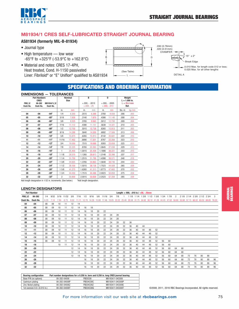
For more information visit our web site at rbcbearings.com
STRAIGHT JOURNAL BEARINGS
75
JOUR
NAL
BEAR
INGS
©2008, 2011, 2016 RBC Bearings Incorporated. All rights reserved.
M81934/1 CRES SELF-LUBRICATED STRAIGHT JOURNAL BEARINGAS81934 (formerly MIL-B-81934)• Journal type
• High temperature — low wear -65°F to +325°F (-53.9°C to +162.8°C)
• Material and notes: CRES 17-4PH, Heat treated, Cond. H-1150 passivatedLiner: Fibriloid® or “E” Uniflon® qualified to AS81934
LENGTH DESIGNATORSPart Number Length: + 000, -.010 in./ +00, -.25mm
PBE( )C 06-282 1/4 9/32 5/16 11/32 3/8 7/16 1/2 9/16 5/8 11/16 3/4 7/8 1 1 1/8 1 1/4 1 3/8 1 1/2 1 5/8 1 3/4 1 7/8 2 2 1/8 2 1/4 2 3/8 2 1/2 2 3/4 3
Dash No. Dash No. 6.35 7.14 7.94 8.73 9.52 11.11 12.70 14.29 15.88 17.46 19.05 22.22 25.40 28.58 31.75 34.92 38.10 41.28 44.45 47.62 50.80 53.98 57.15 60.32 63.50 69.85 76.20
04 -04 08 09 10 11 12 14
05 -05 08 09 10 11 12 14 16 18
06 -06 08 09 10 11 12 14 16 18 20 22
07 -07 08 09 10 11 12 14 16 18 20 22 24 28
08 -08 08 09 10 11 12 14 16 18 20 22 24 28
09 -09 08 09 10 11 12 14 16 18 20 22 24 28 32 36
10 -10 08 09 10 11 12 14 16 18 20 22 24 28 32 36 40 44
11 -11 08 09 10 11 12 14 16 18 20 22 24 28 32 36 40 44 48 52
12 -12 08 09 10 11 12 14 16 18 20 22 24 28 32 36 40 44 48 52
14 -14 08 09 10 11 12 14 16 18 20 22 24 28 32 36 40 44 48 52
16 -16 08 09 10 11 12 14 16 18 20 22 24 28 32 36 40 44 48 52 56 60
18 -18 10 11 12 14 16 18 20 22 24 28 32 36 40 44 48 52 56 60
20 -20 12 14 16 18 20 22 24 28 32 36 40 44 48 52 56 60 64 68
22 -22 12 14 16 18 20 22 24 28 32 36 40 44 48 52 56 60 64 68
24 -24 12 14 16 18 20 22 24 28 32 36 40 44 48 52 56 60 64 68 72 76 80 88
26 -26 16 18 20 22 24 28 32 36 40 44 48 52 56 60 64 68 72 76 80 88 96
28 -28 16 18 20 22 24 28 32 36 40 44 48 52 56 60 64 68 72 76 80 88 96
32 -32 16 18 20 22 24 28 32 36 40 44 48 52 56 60 64 68 72 76 80 88 96
Bearing configuration Part number designations for a 0.250 in. bore and 0.250 in. long CRES journal bearingBase P/N (no options) 06-282-04008 PBE0C08 M81934/1-04C008Cadmium plating 06-282-04008P PBE04C08C M81934/1-04C008PZinc Nickel plating 06-282-04008Z PBE04C08Z M81934/1-04C008E1st oversize O.D. (0.010 in.) 06-282-04008T PBE04C08Q M81934/1-04C008T
SPECIFICATIONS AND ORDERING INFORMATION
B D
L
(See Table)
.030 (0.76mm)
.020 (0.51mm)
Break Edge
15° ± 2°
0.010 Max. for length code 012 or less; 0.025 Max. for all other lengths
CHAMFER
DETAIL A
A
DIMENSIONS — TOLERANCES
in. mm in. mm in. mm lbs.-in kg-mm
04 -04 -04† 1/4 6.350 .2515 6.388 .3760 9.550 .006 .003
05 -05 -05† 5/16 7.938 .3140 7.976 .4386 11.140 .008 .004
06 -06 -06† 3/8 9.525 .3765 9.563 .5012 12.730 .009 .004
07 -07 -07† 7/16 11.112 .4390 11.151 .5638 14.321 .010 .005
08 -08 -08† 1/2 12.700 .5015 12.738 .6265 15.913 .011 .005
09 -09 -09† 9/16 14.288 .5640 14.326 .6892 17.506 .013 .006
10 -10 -10† 5/8 15.875 .6265 15.913 .8142 20.681 .022 .010
11 -11 -11† 11/16 17.462 .6890 17.501 .8767 22.268 .023 .010
12 -12 -12† 3/4 19.050 .7515 19.088 .9393 23.858 .025 .011
14 -14 -14† 7/8 22.225 .8765 22.263 1.0645 27.038 .029 .013
16 -16 -16† 1 25.400 1.0015 25.438 1.1898 38.221 .033 .015
18 -18 -18† 1 1/8 28.575 1.1265 28.613 1.3148 33.396 .037 .017
20 -20 -20† 1 1/4 31.750 1.2515 31.788 1.4398 38.571 .040 .018
22 -22 -22† 1 3/8 34.925 1.3765 34.963 1.5648 39.746 .044 .020
24 -24 -24† 1 1/2 38.100 1.5015 38.138 1.7523 44.508 .065 .029
26 -26 -26† 1 5/8 41.275 1.6265 41.313 1.8773 47.683 .070 .032
28 -28 -28† 1 3/4 44.450 1.7515 44.488 2.0023 50.858 .075 .034
32 -32 -32† 2 50.800 2.0015 50.838 2.2523 57.208 .085 .039
Add length designation in 1/32 in. increments. (See below.) †Add length designation.
Weight L = 1.000 in.L = 25.4 mm
Ref.
D
+.000, - .0005 +.000, -.013
B
+.000, - .0010 +.000, -.25
NominalSize
Part NumbersCRES
PBE( )C 06-282 M81934/1( )CDash No. Dash No. Dash No.
PB_073_097_8-30-16_Pln_079_103.qxd 8/30/16 11:08 AM Page 75

For more information visit our web site at rbcbearings.com
FLANGED JOURNAL BEARINGS
76
JOUR
NAL
BEAR
INGS
©2008, 2011, 2016 RBC Bearings Incorporated. All rights reserved.
DIMENSIONS — TOLERANCESAluminum
in. mm in. mm in. mm in. mm in. mm lbs.-in kg-mm lbs.-in kg-mm
04 -04 -04† 1/4 6.350 .2515 6.388 .3760 9.550 .0625 1.588 .750 19.05 .009 .004 .003 .001
05 -05 -05† 5/16 7.938 .3140 7.976 .4386 11.140 .0625 1.588 .812 20.62 .011 .005 .003 .001
06 -06 -06† 3/8 9.525 .3765 9.563 .5012 12.730 .0625 1.588 .875 22.22 .012 .005 .003 .001
07 -07 -07† 7/16 11.112 .4390 11.151 .5638 14.321 .0625 1.588 .937 23.80 .013 .006 .003 .001
08 -08 -08† 1/2 12.700 .5015 12.738 .6265 15.913 .0625 1.588 1.000 25.40 .015 .007 .004 .002
09 -09 -09† 9/16 14.288 .5640 14.326 .6892 17.506 .0625 1.588 1.125 28.58 .017 .008 .004 .002
10 -10 -10† 5/8 15.875 .6265 15.913 .8142 20.681 .0625 1.588 1.250 31.75 .027 .012 .005 .002
11 -11 -11† 11/16 17.462 .6890 17.501 .8767 22.268 .0625 1.588 1.375 34.92 .030 .014 .007 .003
12 -12 -12† 3/4 19.050 .7515 19.088 .9393 23.858 .0625 1.588 1.500 38.10 .034 .015 .009 .004
14 -14 -14† 7/8 22.225 .8765 22.263 1.0645 27.038 .0625 1.588 1.625 41.28 .038 .017 .009 .004
16 -16 -16† 1 25.400 1.0015 25.438 1.1898 30.221 .0625 1.588 1.750 44.45 .043 .020 .010 .005
18 -18 -18† 1 1/8 28.575 1.1265 28.613 1.3148 33.396 .0937 2.380 1.875 47.62 .051 .023 .014 .006
20 -20 -20† 1 1/4 31.750 1.2515 31.788 1.4398 36.571 .0937 2.380 2.000 50.80 .058 .026 .018 .008
22 -22 -22† 1 3/8 34.925 1.3765 34.963 1.5648 39.746 .0937 2.380 2.125 53.98 .063 .029 .019 .009
24 -24 -24† 1 1/2 38.100 1.5015 38.138 1.7523 44.508 .0937 2.380 2.250 57.15 .084 .038 .018 .008
26 -26 -26† 1 5/8 41.275 1.6265 41.313 1.8773 47.683 .0937 2.380 2.375 60.32 .090 .041 .020 .009
28 -28 -28† 1 3/4 44.450 1.7515 44.488 2.0023 50.858 .0937 2.380 2.500 63.50 .098 .044 .023 .010
32 -32 -32† 2 50.800 2.0015 50.838 2.2523 57.208 .0937 2.380 2.750 69.85 .111 .050 .026 .012
Add length designation in 1/32 in. increments. (See below.) †Add length designation.
FlangeWeight
Journal WeightL = 1.000 in.L = 25.4 mm
Ref.
H
+.000, - .020 +.00, -.51
F
+.000, - .005 +.00, -.13
D
±0005±013
B
+.000, - .0010 +.000, -.25
NominalSize
Part NumbersAluminum
FBE( )A 07-382 M81934/2( )ADash No. Dash No. Dash No.
AS81934/2 (formerly MIL-B-81934)• Flanged journal type
• High temperature — low wear -65°F to +325°F (-53.9°C to +162.8°C)
• Material: Aluminum alloy, Cond. T8511anodized or chemical-film treatedLiner: Fibriloid® or “E” Uniflon® qualifiedto AS81934
H
B
+ .100
Max.D
L (SEE TABLE)F
.030 (0.76mm)
.020 (0.51mm)
Break Edge or Chamfer.020 (0.51mm) x 45° Max.
15° ± 2°
CHAMFER
DETAIL A DETAIL B
AB
B.005 Max.(0.13mm)
.045 Max.(1.14mm)
.020 Max.(0.51mm)
F
.062 Max.(1.57mm)
Break Edge or Chamfer.015 (0.38mm) x 45° Max..010 Max.
(0.25mm) for length code 012 or less; .025 Max. (0.64mm) for all other lengths
.010± .005R(0.25mm ±0.13mm)
M81934/2 ALUMINUM SELF-LUBRICATED FLANGED JOURNAL BEARING
LENGTH DESIGNATORSPart Number Length: + 000, -.010 in./ +00, -.25mm
FBE( )A 07-382 1/4 9/32 5/16 11/32 3/8 7/16 1/2 9/16 5/8 11/16 3/4 7/8 1 1 1/8 1 1/4 1 3/8 1 1/2 1 5/8 1 3/4 1 7/8 2 2 1/8 2 1/4 2 3/8 2 1/2 2 3/4 3
Dash No. Dash No. 6.35 7.14 7.94 8.73 9.52 11.11 12.70 14.29 15.88 17.46 19.05 22.22 25.40 28.58 31.75 34.92 38.10 41.28 44.45 47.62 50.80 53.98 57.15 60.32 63.50 69.85 76.20
04 -04 08 09 10 11 12 14
05 -05 08 09 10 11 12 14 16 18
06 -06 08 09 10 11 12 14 16 18 20 22
07 -07 08 09 10 11 12 14 16 18 20 22 24 28
08 -08 08 09 10 11 12 14 16 18 20 22 24 28
09 -09 08 09 10 11 12 14 16 18 20 22 24 28 32 36
10 -10 08 09 10 11 12 14 16 18 20 22 24 28 32 36 40 44
11 -11 08 09 10 11 12 14 16 18 20 22 24 28 32 36 40 44 48 52
12 -12 08 09 10 11 12 14 16 18 20 22 24 28 32 38 40 44 48 52
14 -14 08 09 10 11 12 14 16 18 20 22 24 28 32 36 40 44 48 52
16 -16 08 09 10 11 12 14 16 18 20 22 24 28 32 36 40 44 48 52 56 60
18 -18 10 11 12 14 16 18 20 22 24 28 32 36 40 44 48 52 56 60
20 -20 12 14 16 18 20 22 24 28 32 36 40 44 48 52 56 60 64 68
22 -22 12 14 16 18 20 22 24 28 32 36 40 44 48 52 56 60 64 68
24 -24 12 14 16 18 20 22 24 28 32 36 40 44 48 52 56 60 64 68 72 76 80 88
26 -26 16 18 20 22 24 28 32 36 40 44 48 52 56 60 64 68 72 76 80 88 96
28 -28 16 18 20 22 24 28 32 36 40 44 48 52 56 60 64 68 72 76 80 88 96
32 -32 16 18 20 22 24 28 32 36 40 44 48 52 56 60 64 68 72 76 80 88 96
SPECIFICATIONS AND ORDERING INFORMATION
Bearing configuration Part number designations for a 0.250 in. bore and 0.250 in. long aluminum journal bearingBase P/N (no options) 07-382-04008 FBE04A08 M81934/2-04A0081st oversize O.D. (0.010 in.) 07-382-04008T FBE04A08Q M81934/2-04A008T2nd oversize O.D. (0.020 in.) 07-382-04008U FBE04A08U M81934/2-04A008U
PB_073_097_8-30-16_Pln_079_103.qxd 8/30/16 11:08 AM Page 76
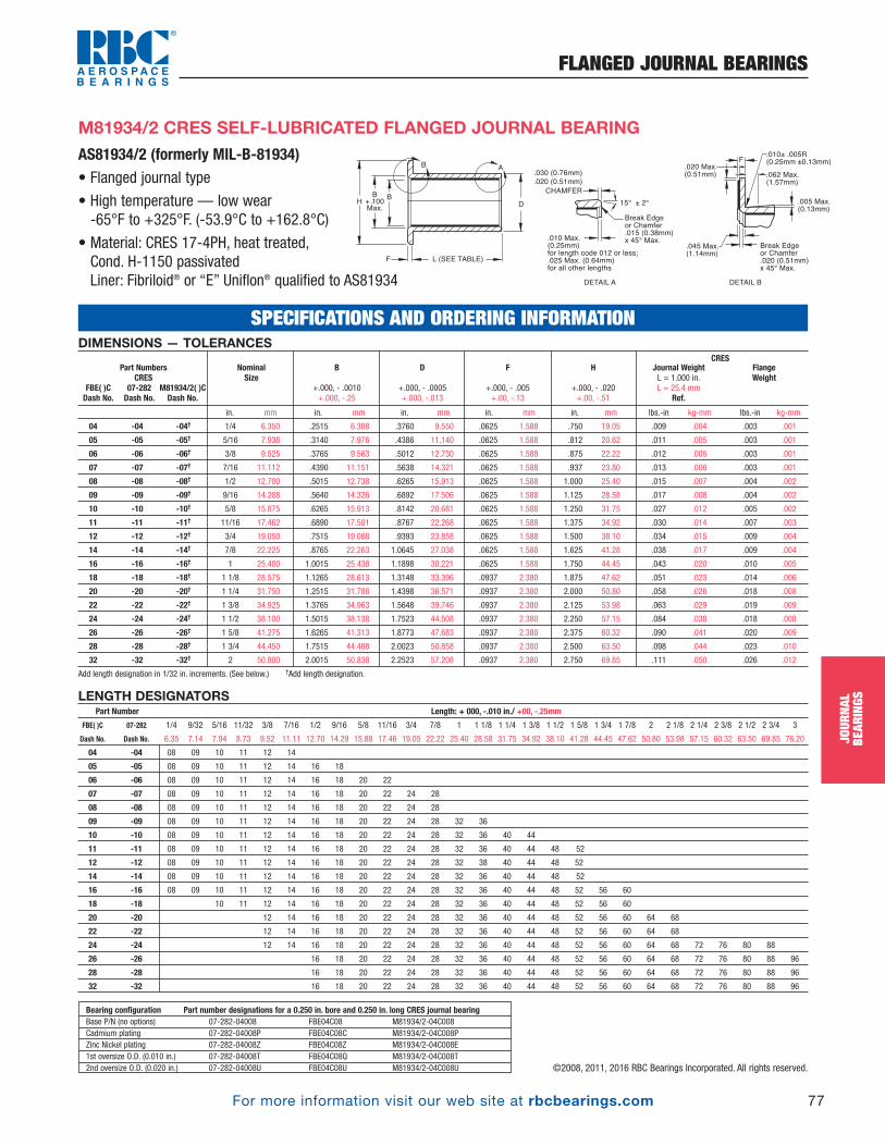
For more information visit our web site at rbcbearings.com
FLANGED JOURNAL BEARINGS
77
JOUR
NAL
BEAR
INGS
©2008, 2011, 2016 RBC Bearings Incorporated. All rights reserved.
DIMENSIONS — TOLERANCESCRES
in. mm in. mm in. mm in. mm in. mm lbs.-in kg-mm lbs.-in kg-mm
04 -04 -04† 1/4 6.350 .2515 6.388 .3760 9.550 .0625 1.588 .750 19.05 .009 .004 .003 .001
05 -05 -05† 5/16 7.938 .3140 7.976 .4386 11.140 .0625 1.588 .812 20.62 .011 .005 .003 .001
06 -06 -06† 3/8 9.525 .3765 9.563 .5012 12.730 .0625 1.588 .875 22.22 .012 .005 .003 .001
07 -07 -07† 7/16 11.112 .4390 11.151 .5638 14.321 .0625 1.588 .937 23.80 .013 .006 .003 .001
08 -08 -08† 1/2 12.700 .5015 12.738 .6265 15.913 .0625 1.588 1.000 25.40 .015 .007 .004 .002
09 -09 -09† 9/16 14.288 .5640 14.326 .6892 17.506 .0625 1.588 1.125 28.58 .017 .008 .004 .002
10 -10 -10† 5/8 15.875 .6265 15.913 .8142 20.681 .0625 1.588 1.250 31.75 .027 .012 .005 .002
11 -11 -11† 11/16 17.462 .6890 17.501 .8767 22.268 .0625 1.588 1.375 34.92 .030 .014 .007 .003
12 -12 -12† 3/4 19.050 .7515 19.088 .9393 23.858 .0625 1.588 1.500 38.10 .034 .015 .009 .004
14 -14 -14† 7/8 22.225 .8765 22.263 1.0645 27.038 .0625 1.588 1.625 41.28 .038 .017 .009 .004
16 -16 -16† 1 25.400 1.0015 25.438 1.1898 30.221 .0625 1.588 1.750 44.45 .043 .020 .010 .005
18 -18 -18† 1 1/8 28.575 1.1265 28.613 1.3148 33.396 .0937 2.380 1.875 47.62 .051 .023 .014 .006
20 -20 -20† 1 1/4 31.750 1.2515 31.788 1.4398 36.571 .0937 2.380 2.000 50.80 .058 .026 .018 .008
22 -22 -22† 1 3/8 34.925 1.3765 34.963 1.5648 39.746 .0937 2.380 2.125 53.98 .063 .029 .019 .009
24 -24 -24† 1 1/2 38.100 1.5015 38.138 1.7523 44.508 .0937 2.380 2.250 57.15 .084 .038 .018 .008
26 -26 -26† 1 5/8 41.275 1.6265 41.313 1.8773 47.683 .0937 2.380 2.375 60.32 .090 .041 .020 .009
28 -28 -28† 1 3/4 44.450 1.7515 44.488 2.0023 50.858 .0937 2.380 2.500 63.50 .098 .044 .023 .010
32 -32 -32† 2 50.800 2.0015 50.838 2.2523 57.208 .0937 2.380 2.750 69.85 .111 .050 .026 .012
Add length designation in 1/32 in. increments. (See below.) †Add length designation.
FlangeWeight
Journal WeightL = 1.000 in.L = 25.4 mm
Ref.
H
+.000, - .020 +.00, -.51
F
+.000, - .005 +.00, -.13
D
+.000, - .0005 +.000, -.013
B
+.000, - .0010 +.000, -.25
NominalSize
Part NumbersCRES
FBE( )C 07-282 M81934/2( )CDash No. Dash No. Dash No.
AS81934/2 (formerly MIL-B-81934)• Flanged journal type
• High temperature — low wear -65°F to +325°F. (-53.9°C to +162.8°C)
• Material: CRES 17-4PH, heat treated, Cond. H-1150 passivatedLiner: Fibriloid® or “E” Uniflon® qualified to AS81934
M81934/2 CRES SELF-LUBRICATED FLANGED JOURNAL BEARING
LENGTH DESIGNATORSPart Number Length: + 000, -.010 in./ +00, -.25mm
FBE( )C 07-282 1/4 9/32 5/16 11/32 3/8 7/16 1/2 9/16 5/8 11/16 3/4 7/8 1 1 1/8 1 1/4 1 3/8 1 1/2 1 5/8 1 3/4 1 7/8 2 2 1/8 2 1/4 2 3/8 2 1/2 2 3/4 3
Dash No. Dash No. 6.35 7.14 7.94 8.73 9.52 11.11 12.70 14.29 15.88 17.46 19.05 22.22 25.40 28.58 31.75 34.92 38.10 41.28 44.45 47.62 50.80 53.98 57.15 60.32 63.50 69.85 76.20
04 -04 08 09 10 11 12 14
05 -05 08 09 10 11 12 14 16 18
06 -06 08 09 10 11 12 14 16 18 20 22
07 -07 08 09 10 11 12 14 16 18 20 22 24 28
08 -08 08 09 10 11 12 14 16 18 20 22 24 28
09 -09 08 09 10 11 12 14 16 18 20 22 24 28 32 36
10 -10 08 09 10 11 12 14 16 18 20 22 24 28 32 36 40 44
11 -11 08 09 10 11 12 14 16 18 20 22 24 28 32 36 40 44 48 52
12 -12 08 09 10 11 12 14 16 18 20 22 24 28 32 38 40 44 48 52
14 -14 08 09 10 11 12 14 16 18 20 22 24 28 32 36 40 44 48 52
16 -16 08 09 10 11 12 14 16 18 20 22 24 28 32 36 40 44 48 52 56 60
18 -18 10 11 12 14 16 18 20 22 24 28 32 36 40 44 48 52 56 60
20 -20 12 14 16 18 20 22 24 28 32 36 40 44 48 52 56 60 64 68
22 -22 12 14 16 18 20 22 24 28 32 36 40 44 48 52 56 60 64 68
24 -24 12 14 16 18 20 22 24 28 32 36 40 44 48 52 56 60 64 68 72 76 80 88
26 -26 16 18 20 22 24 28 32 36 40 44 48 52 56 60 64 68 72 76 80 88 96
28 -28 16 18 20 22 24 28 32 36 40 44 48 52 56 60 64 68 72 76 80 88 96
32 -32 16 18 20 22 24 28 32 36 40 44 48 52 56 60 64 68 72 76 80 88 96
Bearing configuration Part number designations for a 0.250 in. bore and 0.250 in. long CRES journal bearingBase P/N (no options) 07-282-04008 FBE04C08 M81934/2-04C008Cadmium plating 07-282-04008P FBE04C08C M81934/2-04C008PZinc Nickel plating 07-282-04008Z FBE04C08Z M81934/2-04C008E1st oversize O.D. (0.010 in.) 07-282-04008T FBE04C08Q M81934/2-04C008T2nd oversize O.D. (0.020 in.) 07-282-04008U FBE04C08U M81934/2-04C008U
SPECIFICATIONS AND ORDERING INFORMATION
H
B
+ .100
Max.D
L (SEE TABLE)F
.030 (0.76mm)
.020 (0.51mm)
Break Edge or Chamfer.020 (0.51mm) x 45° Max.
15° ± 2°
CHAMFER
DETAIL A DETAIL B
AB
B.005 Max.(0.13mm)
.045 Max.(1.14mm)
.020 Max.(0.51mm)
F
.062 Max.(1.57mm)
Break Edge or Chamfer.015 (0.38mm) x 45° Max..010 Max.
(0.25mm) for length code 012 or less; .025 Max. (0.64mm) for all other lengths
.010± .005R(0.25mm ±0.13mm)
PB_073_097_8-30-16_Pln_079_103.qxd 8/30/16 11:08 AM Page 77

For more information visit our web site at rbcbearings.com
STRAIGHT JOURNAL BEARINGS
78
JOUR
NAL
BEAR
INGS
©2008, 2011, 2016 RBC Bearings Incorporated. All rights reserved.
European Standards• Bushes (journal) type
• High temperature — low wear-55°C to +163°C (-65°F to +325°F)
• Material and notes:Aluminum alloy, Cond. T8511 anodized perMIL-A-8625, according to EN 2086, EN 2701 orEN 2704. Anodized per EN 2101A or EN 2284ALiner: Fibriloid® or “E” Uniflon® qualified toAS81934, according to EN 2311
EN 2285 ALUMINUM SELF-LUBRICATED STRAIGHT JOURNAL BEARING
EN 2285 Aluminum Self-lubricated Straight Journal BearingB D Length
nom tol nom tol 6 8 10 12 15 16 18 20 22 25 28 30 32 35 40 45 50
p6 L -0.1-0.4
Mass in kg/1000 pcs
6 +0.022 +0.004 10 +0.024 -0.015 0.9
8 +0.027 +0.005 12 +0.029 +0.018 1.1 1.4
10 +0.027 +0.005 14 +0.029 +0.018 1.3 1.7 2.1
12 +0.027 +0.005 16 +0.029 +0.018 1.5 2.0 2.5 3.0
15 +0.033 +0.006 19 +0.035 +0.022 2.4 3.0 3.6 4.6
16 +0.033 +0.006 20 +0.035 +0.022 2.6 3.2 3.8 4.8 5.1
18 +0.033 +0.006 22 +0.035 +0.022 3.6 4.3 5.5 6.6
20 +0.04 +0.007 25 +0.035 +0.022 5.0 6.0 7.5 10.0
22 +0.04 +0.007 26 +0.035 +0.022 5.1 6.4 8.5 9.4
25 +0.04 +0.007 30 +0.035 +0.022 7.4 9.2 12.5 13.5 15.3
28 +0.04 +0.007 34 +0.042 +0.026 12.4 16.6 18.2 20.7 23.2
30 +0.04 +0.007 36 +0.042 +0.026 13.3 17.7 19.5 22.1 26.5
32 +0.048 +0.009 38 +0.042 +0.026 14.0 18.7 20.5 23.5 28.0 29.9
35 +0.048 +0.009 42 +0.042 +0.026 24.0 26.5 30.1 36.0 42.2
40 +0.048 +0.009 48 +0.051 +0.032 31.0 39.0 46.9 54.9 62.8
45 +0.048 +0.009 52 +0.051 +0.032 38.0 45.6 53.1 60.7 68.2
50 +0.048 +0.009 58 +0.051 +0.032 48.7 58.2 67.7 77.3 86.8 96.4
Dimensions in millimeters
Load Calculations
Static radial limit load = 0.206B x (L-2) kN
Permissible dynamic load = Static radial limit load / 1.2 kN
Where:
B = Bush bore
L = Bush length
SPECIFICATIONS AND ORDERING INFORMATION
B D
L
(See Table)
.030 (0.76mm)
.020 (0.51mm)
Break Edge
15° ± 2°
0.010 Max. for length code 012 or less; 0.025 Max. for all other lengths
CHAMFER
DETAIL A
A
PB_073_097_8-30-16_Pln_079_103.qxd 8/30/16 11:08 AM Page 78
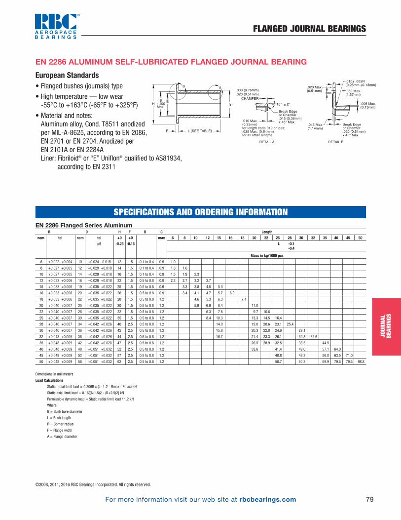
For more information visit our web site at rbcbearings.com
FLANGED JOURNAL BEARINGS
79
JOUR
NAL
BEAR
INGS
©2008, 2011, 2016 RBC Bearings Incorporated. All rights reserved.
European Standards• Flanged bushes (journals) type
• High temperature — low wear-55°C to +163°C (-65°F to +325°F)
• Material and notes:Aluminum alloy, Cond. T8511 anodized per MIL-A-8625, according to EN 2086, EN 2701 or EN 2704. Anodized per EN 2101A or EN 2284ALiner: Fibriloid® or “E” Uniflon® qualified to AS81934,
according to EN 2311
EN 2286 ALUMINUM SELF-LUBRICATED FLANGED JOURNAL BEARING
EN 2286 Flanged Series Aluminum B D H F R C Length
nom tol nom tol +0 +0 max 6 8 10 12 15 16 18 20 22 25 28 30 32 35 40 45 50
p6 -0.25 -0.15 L -0.1-0.4
Mass in kg/1000 pcs
6 +0.022 +0.004 10 +0.024 -0.015 12 1.5 0.1 to 0.4 0.9 1.0
8 +0.027 +0.005 12 +0.029 +0.018 14 1.5 0.1 to 0.4 0.9 1.3 1.6
10 +0.027 +0.005 14 +0.029 +0.018 16 1.5 0.1 to 0.4 0.9 1.5 1.9 2.3
12 +0.033 +0.006 16 +0.029 +0.018 22 1.5 0.5 to 0.8 0.9 2.3 2.7 3.2 3.7
15 +0.033 +0.006 19 +0.035 +0.022 25 1.5 0.5 to 0.8 0.9 3.3 3.8 4.5 5.0
16 +0.033 +0.006 20 +0.035 +0.022 26 1.5 0.5 to 0.8 0.9 3.4 4.1 4.7 5.7 6.0
18 +0.033 +0.006 22 +0.035 +0.022 28 1.5 0.5 to 0.8 1.2 4.6 5.3 6.3 7.4
20 +0.040 +0.007 25 +0.035 +0.022 30 1.5 0.5 to 0.8 1.2 5.9 6.9 8.4 11.0
22 +0.040 +0.007 26 +0.035 +0.022 32 1.5 0.5 to 0.8 1.2 6.3 7.6 9.7 10.6
25 +0.040 +0.007 30 +0.035 +0.022 35 1.5 0.5 to 0.8 1.2 8.4 10.3 13.3 14.5 16.4
28 +0.040 +0.007 34 +0.042 +0.026 40 2.5 0.5 to 0.8 1.2 14.9 19.0 20.6 23.1 25.4
30 +0.040 +0.007 36 +0.042 +0.026 42 2.5 0.5 to 0.8 1.2 15.8 20.3 22.0 24.6 29.1
32 +0.048 +0.009 38 +0.042 +0.026 44 2.5 0.5 to 0.8 1.2 16.7 21.4 23.3 26.1 30.8 32.6
35 +0.048 +0.009 42 +0.042 +0.026 47 2.5 0.5 to 0.8 1.2 26.5 28.9 32.5 38.5 44.5
40 +0.048 +0.009 48 +0.051 +0.032 52 2.5 0.5 to 0.8 1.2 33.6 41.4 49.0 57.1 64.0
45 +0.048 +0.009 52 +0.051 +0.032 57 2.5 0.5 to 0.8 1.2 40.8 48.3 56.0 63.5 71.0
50 +0.048 +0.009 58 +0.051 +0.032 62 2.5 0.5 to 0.8 1.2 50.7 60.3 69.9 79.6 79.6 98.8
Dimensions in millimeters
Load Calculations
Static radial limit load = 0.206B x (L- 1.2 - Rmax - Fmax) kN
Static axial limit load = 0.16[(A-1.5)2 - (B+2.5)2] kN
Permissible dynamic load = Static radial limit load / 1.2 kN
Where:
B = Bush bore diameter
L = Bush length
R = Corner radius
F = Flange width
A = Flange diameter
SPECIFICATIONS AND ORDERING INFORMATION
H
B
+ .100
Max.D
L (SEE TABLE)F
.030 (0.76mm)
.020 (0.51mm)
Break Edge or Chamfer.020 (0.51mm) x 45° Max.
15° ± 2°
CHAMFER
DETAIL A DETAIL B
AB
B.005 Max.(0.13mm)
.045 Max.(1.14mm)
.020 Max.(0.51mm)
F
.062 Max.(1.57mm)
Break Edge or Chamfer.015 (0.38mm) x 45° Max..010 Max.
(0.25mm) for length code 012 or less; .025 Max. (0.64mm) for all other lengths
.010± .005R(0.25mm ±0.13mm)
PB_073_097_8-30-16_Pln_079_103.qxd 8/30/16 11:08 AM Page 79

For more information visit our web site at rbcbearings.com
STRAIGHT JOURNAL BEARINGS
80
JOUR
NAL
BEAR
INGS
©2008, 2011, 2016 RBC Bearings Incorporated. All rights reserved.
EN 2287 Plain Series CRESB D Length
nom tol nom tol 6 8 10 12 15 16 18 20 22 25 28 30 32 35 40 45 50
p6 L -0.1-0.4
Mass in kg/1000 pcs
6 +0.022 +0.004 10 +0.024 -0.015 2.4
8 +0.027 +0.005 12 +0.029 +0.018 3.0 4.0
10 +0.027 +0.005 14 +0.029 +0.018 3.5 4.7 5.9
12 +0.027 +0.005 16 +0.029 +0.018 4.1 5.5 6.9 8.3
15 +0.033 +0.006 19 +0.035 +0.022 6.7 8.4 10.1 12.6
16 +0.033 +0.006 20 +0.035 +0.022 7.1 8.9 10.7 13.4 14.3
18 +0.033 +0.006 22 +0.035 +0.022 9.9 11.8 14.8 17.8
20 +0.04 +0.007 25 +0.035 +0.022 13.9 16.7 20.9 27.8
22 +0.04 +0.007 26 +0.035 +0.022 14.2 17.8 23.7 26.1
25 +0.04 +0.007 30 +0.035 +0.022 20.4 25.5 34.0 37.4 42.5
28 +0.04 +0.007 34 +0.042 +0.026 34.5 46.0 50.6 57.5 64.4
30 +0.04 +0.007 36 +0.042 +0.026 36.7 49.0 53.8 61.2 73.4
32 +0.048 +0.009 38 +0.042 +0.026 39.0 51.9 57.1 64.9 77.9 83.1
35 +0.048 +0.009 42 +0.042 +0.026 66.6 73.5 83.6 100.3 117.0
40 +0.048 +0.009 48 +0.051 +0.032 87.0 108.8 130.0 152.2 174.0
45 +0.048 +0.009 52 +0.051 +0.032 105.0 126.0 147.0 168.0 189.0
50 +0.048 +0.009 58 +0.051 +0.032 133.5 160.0 186.9 214.0 240.3 267.0
Dimensions in millimeters
Load Calculations
Static radial limit load = 0.43B x (L-2) kN
Permissible dynamic load = Static radial limit load / 2.5 kN
Where:
B = Bush bore
L = Bush length
European Standards• Bushes (journal) type
• High temperature — low wear-55°C to +163°C (-65°F to +325°F)
• Material and notes:CRES 17-4PH, heat treated according to EN 3161 or EN 3490Liner: Fibriloid® or “E” Uniflon® qualified toAS81934, according to EN 2311
EN 2287 CRES SELF-LUBRICATED STRAIGHT JOURNAL BEARING
SPECIFICATIONS AND ORDERING INFORMATION
B D
L
(See Table)
.030 (0.76mm)
.020 (0.51mm)
Break Edge
15° ± 2°
0.010 Max. for length code 012 or less; 0.025 Max. for all other lengths
CHAMFER
DETAIL A
A
PB_073_097_8-30-16_Pln_079_103.qxd 8/30/16 11:08 AM Page 80

For more information visit our web site at rbcbearings.com
FLANGED JOURNAL BEARINGS
81
JOUR
NAL
BEAR
INGS
©2008, 2011, 2016 RBC Bearings Incorporated. All rights reserved.
European Standards• Flanged bushes (journals) type
• High temperature — low wear-55°C to +163°C (-65°F to +325°F)
• Material and notes:CRES 17-4PH, heat treated accordingto EN 3161 or EN 3490Liner: Fibriloid® or “E” Uniflon® qualifiedto AS81934, according to EN 2311
EN 2288 CRES SELF-LUBRICATED FLANGED JOURNAL BEARING
EN 2288 Flanged Series CRES B D H F R C Length
nom tol nom tol +0 +0 max 6 8 10 12 15 16 18 20 22 25 28 30 32 35 40 45 50
p6 -0.25 -0.15 L -0.1-0.4
Mass in kg/1000 pcs
6 +0.022 +0.004 10 +0.024 -0.015 12 1.5 0.1 to 0.4 0.9 2.8
8 +0.027 +0.005 12 +0.029 +0.018 14 1.5 0.1 to 0.4 0.9 3.5 4.4
10 +0.027 +0.005 14 +0.029 +0.018 16 1.5 0.1 to 0.4 0.9 4.1 5.3 6.5
12 +0.033 +0.006 16 +0.029 +0.018 22 1.5 0.5 to 0.8 0.9 6.3 7.6 9.0 10.4
15 +0.033 +0.006 19 +0.035 +0.022 25 1.5 0.5 to 0.8 0.9 9.2 10.8 12.5 15.6
16 +0.033 +0.006 20 +0.035 +0.022 26 1.5 0.5 to 0.8 0.9 9.7 11.5 13.2 15.9 16.8
18 +0.033 +0.006 22 +0.035 +0.022 28 1.5 0.5 to 0.8 1.2 12.7 14.7 17.6 20.8
20 +0.040 +0.007 25 +0.035 +0.022 30 1.5 0.5 to 0.8 1.2 16.5 19.2 23.4 30.4
22 +0.040 +0.007 26 +0.035 +0.022 32 1.5 0.5 to 0.8 1.2 17.5 21.0 27.0 29.3
25 +0.040 +0.007 30 +0.035 +0.022 35 1.5 0.5 to 0.8 1.2 23.4 28.5 37.0 40.4 45.5
28 +0.040 +0.007 34 +0.042 +0.026 40 2.5 0.5 to 0.8 1.2 41.4 52.8 57.4 64.3 71.2
30 +0.040 +0.007 36 +0.042 +0.026 42 2.5 0.5 to 0.8 1.2 43.9 56.2 61.1 68.4 80.7
32 +0.048 +0.009 38 +0.042 +0.026 44 2.5 0.5 to 0.8 1.2 46.5 59.5 61.7 72.5 85.5 90.7
35 +0.048 +0.009 42 +0.042 +0.026 47 2.5 0.5 to 0.8 1.2 73.5 80.2 90.2 106.8 123.5
40 +0.048 +0.009 48 +0.051 +0.032 52 2.5 0.5 to 0.8 1.2 93.2 115.0 136.0 158.5 180.0
45 +0.048 +0.009 52 +0.051 +0.032 57 2.5 0.5 to 0.8 1.2 113.3 138.3 155.3 176.3 197.3
50 +0.048 +0.009 58 +0.051 +0.032 62 2.5 0.5 to 0.8 1.2 140.9 167.6 194.3 221 247.4 274.4
Dimensions in millimeters
SPECIFICATIONS AND ORDERING INFORMATION
H
B
+ .100
Max.D
L (SEE TABLE)F
.030 (0.76mm)
.020 (0.51mm)
Break Edge or Chamfer.020 (0.51mm) x 45° Max.
15° ± 2°
CHAMFER
DETAIL A DETAIL B
AB
B.005 Max.(0.13mm)
.045 Max.(1.14mm)
.020 Max.(0.51mm)
F
.062 Max.(1.57mm)
Break Edge or Chamfer.015 (0.38mm) x 45° Max..010 Max.
(0.25mm) for length code 012 or less; .025 Max. (0.64mm) for all other lengths
.010± .005R(0.25mm ±0.13mm)
PB_073_097_8-30-16_Pln_079_103.qxd 8/30/16 11:08 AM Page 81
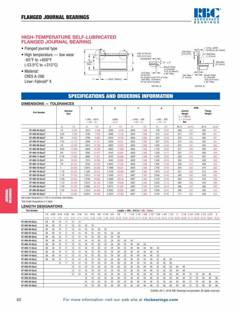
For more information visit our web site at rbcbearings.com
FLANGED JOURNAL BEARINGS
82
JOUR
NAL
BEAR
INGS
©2008, 2011, 2016 RBC Bearings Incorporated. All rights reserved.
DIMENSIONS — TOLERANCESA286
in. mm in. mm in. mm in. mm in. mm lbs.-in kg-mm lbs.-in kg-mm
07-450-04-0(xx)† 1/4 6.350 .2515 6.388 .3760 9.550 .0625 1.588 .750 19.05 .009 .004 .003 .001
07-450-05-0(xx)† 5/16 7.938 .3140 7.976 .4386 11.140 .0625 1.588 .812 20.62 .011 .005 .003 .001
07-450-06-0(xx)† 3/8 9.525 .3765 9.563 .5012 12.730 .0625 1.588 .875 22.22 .012 .005 .003 .001
07-450-07-0(xx)† 7/16 11.112 .4390 11.151 .5638 14.321 .0625 1.588 .937 23.80 .013 .006 .003 .001
07-450-08-0(xx)† 1/2 12.700 .5015 12.738 .6265 15.913 .0625 1.588 1.000 25.40 .015 .007 .004 .002
07-450-09-0(xx)† 9/16 14.288 .5640 14.326 .6892 17.506 .0625 1.588 1.125 28.58 .017 .008 .004 .002
07-450-10-0(xx)† 5/8 15.875 .6265 15.913 .8142 20.681 .0625 1.588 1.250 31.75 .027 .012 .005 .002
07-450-11-0(xx)† 11/16 17.462 .6890 17.501 .8767 22.268 .0625 1.588 1.375 34.92 .030 .014 .007 .003
07-450-12-0(xx)† 3/4 19.050 .7515 19.088 .9393 23.858 .0625 1.588 1.500 38.10 .034 .015 .009 .004
07-450-14-0(xx)† 7/8 22.225 .8765 22.263 1.0645 27.038 .0625 1.588 1.625 41.28 .038 .017 .009 .004
07-450-16-0(xx)† 1 25.400 1.0015 25.438 1.1898 30.221 .0625 1.588 1.750 44.45 .043 .020 .010 .005
07-450-18-0(xx)† 1 1/8 28.575 1.1265 28.613 1.3148 33.396 .0937 2.380 1.875 47.62 .051 .023 .014 .006
07-450-20-0(xx)† 1 1/4 31.750 1.2515 31.788 1.4398 36.571 .0937 2.380 2.000 50.80 .058 .026 .018 .008
07-450-22-0(xx)† 1 3/8 34.925 1.3765 34.963 1.5648 39.746 .0937 2.380 2.125 53.98 .063 .029 .019 .009
07-450-24-0(xx)† 1 1/2 38.100 1.5015 38.138 1.7523 44.508 .0937 2.380 2.250 57.15 .084 .038 .018 .008
07-450-26-0(xx)† 1 5/8 41.275 1.6265 41.313 1.8773 47.683 .0937 2.380 2.375 60.32 .090 .041 .020 .009
07-450-28-0(xx)† 1 3/4 44.450 1.7515 44.488 2.0023 50.858 .0937 2.380 2.500 63.50 .098 .044 .023 .010
07-450-32-0(xx)† 2 50.800 2.0015 50.838 2.2523 57.208 .0937 2.380 2.750 69.85 .111 .050 .026 .012
Add length designation in 1/32 in. increments. (See below.)†Add length designations in 2 digits.
FlangeWeight
JournalWeight
L = 1.000 in.L = 25.4 mm
Ref.
H
+.000, - .020 +.00, -.51
F
+.000, - .005 +.00, -.13
D
±0005±013
B
+.000, - .0010 +.000, -.25
NominalSizePart Number
• Flanged journal type
• High temperature — low wear -65°F to +600°F (-53.9°C to +315°C)
• Material:CRES A-286Liner: Fabroid® X
HIGH-TEMPERATURE SELF-LUBRICATEDFLANGED JOURNAL BEARING
LENGTH DESIGNATORSPart Number Length: + 000, -.010 in./ +00, -.25mm
1/4 9/32 5/16 11/32 3/8 7/16 1/2 9/16 5/8 11/16 3/4 7/8 1 1 1/8 1 1/4 1 3/8 1 1/2 1 5/8 1 3/4 1 7/8 2 2 1/8 2 1/4 2 3/8 2 1/2 2 3/4 3
6.35 7.14 7.94 8.73 9.52 11.11 12.70 14.29 15.88 17.46 19.05 22.22 25.40 28.58 31.75 34.92 38.10 41.28 44.45 47.62 50.80 53.98 57.15 60.32 63.50 69.85 76.20
07-450-04-0(xx) 08 09 10 11 12 14
07-450-05-0(xx) 08 09 10 11 12 14 16 18
07-450-06-0(xx) 08 09 10 11 12 14 16 18 20 22
07-450-07-0(xx) 08 09 10 11 12 14 16 18 20 22 24 28
07-450-08-0(xx) 08 09 10 11 12 14 16 18 20 22 24 28
07-450-09-0(xx) 08 09 10 11 12 14 16 18 20 22 24 28 32 36
07-450-10-0(xx) 08 09 10 11 12 14 16 18 20 22 24 28 32 36 40 44
07-450-11-0(xx) 08 09 10 11 12 14 16 18 20 22 24 28 32 36 40 44 48 52
07-450-12-0(xx) 08 09 10 11 12 14 16 18 20 22 24 28 32 38 40 44 48 52
07-450-14-0(xx) 08 09 10 11 12 14 16 18 20 22 24 28 32 36 40 44 48 52
07-450-16-0(xx) 08 09 10 11 12 14 16 18 20 22 24 28 32 36 40 44 48 52 56 60
07-450-18-0(xx) 10 11 12 14 16 18 20 22 24 28 32 36 40 44 48 52 56 60
07-450-20-0(xx) 12 14 16 18 20 22 24 28 32 36 40 44 48 52 56 60 64 68
07-450-22-0(xx) 12 14 16 18 20 22 24 28 32 36 40 44 48 52 56 60 64 68
07-450-24-0(xx) 12 14 16 18 20 22 24 28 32 36 40 44 48 52 56 60 64 68 72 76 80 88
07-450-26-0(xx) 16 18 20 22 24 28 32 36 40 44 48 52 56 60 64 68 72 76 80 88 96
07-450-28-0(xx) 16 18 20 22 24 28 32 36 40 44 48 52 56 60 64 68 72 76 80 88 96
07-450-32-0(xx) 16 18 20 22 24 28 32 36 40 44 48 52 56 60 64 68 72 76 80 88 96
SPECIFICATIONS AND ORDERING INFORMATION
H
B
+ .100
Max.D
L (SEE TABLE)F
.030 (0.76mm)
.020 (0.51mm)
Break Edge or Chamfer.020 (0.51mm) x 45° Max.
15° ± 2°
CHAMFER
DETAIL A DETAIL B
AB
B.005 Max.(0.13mm)
.045 Max.(1.14mm)
.020 Max.(0.51mm)
F
.062 Max.(1.57mm)
Break Edge or Chamfer.015 (0.38mm) x 45° Max..010 Max.
(0.25mm) for length code 012 or less; .025 Max. (0.64mm) for all other lengths
.010± .005R(0.25mm ±0.13mm)
PB_073_097_8-30-16_Pln_079_103.qxd 8/30/16 11:09 AM Page 82

For more information visit our web site at rbcbearings.com
STRAIGHT JOURNAL BEARINGS
83
JOUR
NAL
BEAR
INGS
©2008, 2011, 2016 RBC Bearings Incorporated. All rights reserved.
HIGH-TEMPERATURE SELF-LUBRICATEDSTRAIGHT JOURNAL BEARING• Journal type
• High temperature — low wear-65°F to +600°F (-53.9°C to +315°C)
• Material:CRES A-286Liner: Fabroid® X
DIMENSIONS — TOLERANCES
in. mm in. mm in. mm lbs.-in kg-mm
06-450-04-(xxx)† 1/4 6.350 .2515 6.388 .3760 9.550 .009 .004
06-450-05-(xxx)† 5/16 7.938 .3140 7.976 .4386 11.140 .011 .005
06-450-06-(xxx)† 3/8 9.525 .3765 9.563 .5012 12.730 .012 .005
06-450-07-(xxx)† 7/16 11.112 .4390 11.151 .5638 14.321 .013 .006
06-450-08-(xxx)† 1/2 12.700 .5015 12.738 .6265 15.913 .015 .007
06-450-09-(xxx)† 9/16 14.288 .5640 14.326 .6892 17.506 .017 .008
06-450-10-(xxx)† 5/8 15.875 .6265 15.913 .8142 20.681 .027 .012
06-450-11-(xxx)† 11/16 17.462 .6890 17.501 .8767 22.268 .030 .014
06-450-12-(xxx)† 3/4 19.050 .7515 19.088 .9393 23.858 .034 .015
06-450-14-(xxx)† 7/8 22.225 .8765 22.263 1.0645 27.038 .038 .017
06-450-16-(xxx)† 1 25.400 1.0015 25.438 1.1898 30.221 .043 .020
06-450-18-(xxx)† 1 1/8 28.575 1.1265 28.613 1.3148 33.396 .051 .023
06-450-20-(xxx)† 1 1/4 31.750 1.2515 31.788 1.4398 36.571 .058 .026
06-450-22-(xxx)† 1 3/8 34.925 1.3765 34.963 1.5648 39.746 .063 .029
06-450-24-(xxx)† 1 1/2 38.100 1.5015 38.138 1.7523 44.508 .084 .038
06-450-26-(xxx)† 1 5/8 41.275 1.6265 41.313 1.8773 47.683 .090 .041
06-450-28-(xxx)† 1 3/4 44.450 1.7515 44.488 2.0023 50.858 .098 .044
06-450-32-(xxx)† 2 50.800 2.0015 50.838 2.2523 57.208 .111 .050
Add length designation in 1/32 in. increments. (See below.)†Add length designations in 3 digits.
JournalWeight
L = 1.000 in.L = 25.4 mm
Ref.
D
±0005±013
B
+.000, - .0010 +.000, -.25
NominalSizePart Number
LENGTH DESIGNATORSPart Number Length: + 000, -.010 in./ +00, -.25mm
1/4 9/32 5/16 11/32 3/8 7/16 1/2 9/16 5/8 11/16 3/4 7/8 1 1 1/8 1 1/4 1 3/8 1 1/2 1 5/8 1 3/4 1 7/8 2 2 1/8 2 1/4 2 3/8 2 1/2 2 3/4 3
6.35 7.14 7.94 8.73 9.52 11.11 12.70 14.29 15.88 17.46 19.05 22.22 25.40 28.58 31.75 34.92 38.10 41.28 44.45 47.62 50.80 53.98 57.15 60.32 63.50 69.85 76.20
06-450-04-0(xx) 08 09 10 11 12 14
06-450-05-0(xx) 08 09 10 11 12 14 16 18
06-450-06-0(xx) 08 09 10 11 12 14 16 18 20 22
06-450-07-0(xx) 08 09 10 11 12 14 16 18 20 22 24 28
06-450-08-0(xx) 08 09 10 11 12 14 16 18 20 22 24 28
06-450-09-0(xx) 08 09 10 11 12 14 16 18 20 22 24 28 32 36
06-450-10-0(xx) 08 09 10 11 12 14 16 18 20 22 24 28 32 36 40 44
06-450-11-0(xx) 08 09 10 11 12 14 16 18 20 22 24 28 32 36 40 44 48 52
06-450-12-0(xx) 08 09 10 11 12 14 16 18 20 22 24 28 32 38 40 44 48 52
06-450-14-0(xx) 08 09 10 11 12 14 16 18 20 22 24 28 32 36 40 44 48 52
06-450-16-0(xx) 08 09 10 11 12 14 16 18 20 22 24 28 32 36 40 44 48 52 56 60
06-450-18-0(xx) 10 11 12 14 16 18 20 22 24 28 32 36 40 44 48 52 56 60
06-450-20-0(xx) 12 14 16 18 20 22 24 28 32 36 40 44 48 52 56 60 64 68
06-450-22-0(xx) 12 14 16 18 20 22 24 28 32 36 40 44 48 52 56 60 64 68
06-450-24-0(xx) 12 14 16 18 20 22 24 28 32 36 40 44 48 52 56 60 64 68 72 76 80 88
06-450-26-0(xx) 16 18 20 22 24 28 32 36 40 44 48 52 56 60 64 68 72 76 80 88 96
06-450-28-0(xx) 16 18 20 22 24 28 32 36 40 44 48 52 56 60 64 68 72 76 80 88 96
06-450-32-0(xx) 16 18 20 22 24 28 32 36 40 44 48 52 56 60 64 68 72 76 80 88 96
SPECIFICATIONS AND ORDERING INFORMATION
B D
L
(See Table)
.030 (0.76mm)
.020 (0.51mm)
Break Edge
15° ± 2°
0.010 Max. for length code 012 or less; 0.025 Max. for all other lengths
CHAMFER
DETAIL A
A
PB_073_097_8-30-16_Pln_079_103.qxd 8/30/16 11:09 AM Page 83

For more information visit our web site at rbcbearings.com
STRAIGHT JOURNAL BEARINGS
84
JOUR
NAL
BEAR
INGS
©2008, 2011, 2016 RBC Bearings Incorporated. All rights reserved.
DIMENSIONS — TOLERANCES
in. mm in. mm in. mm lbs.-in kg-mm
04 -04† 1/4 6.350 .2515 6.388 .3760 9.550 .006 .003
05 -05† 5/16 7.938 .3140 7.976 .4386 11.140 .008 .004
06 -06† 3/8 9.525 .3765 9.563 .5012 12.730 .009 .004
07 -07† 7/16 11.112 .4390 11.151 .5638 14.321 .010 .005
08 -08† 1/2 12.700 .5015 12.738 .6265 15.913 .011 .005
09 -09† 9/16 14.288 .5640 14.326 .6892 17.506 .013 .006
10 -10† 5/8 15.875 .6265 15.913 .8142 20.681 .022 .010
11 -11† 11/16 17.462 .6890 17.501 .8767 22.268 .023 .010
12 -12† 3/4 19.050 .7515 19.088 .9393 23.858 .025 .011
14 -14† 7/8 22.225 .8765 22.263 1.0645 27.038 .029 .013
16 -16† 1 25.400 1.0015 25.438 1.1898 38.221 .033 .015
18 -18† 1 1/8 28.575 1.1265 28.613 1.3148 33.396 .037 .017
20 -20† 1 1/4 31.750 1.2515 31.788 1.4398 38.571 .040 .018
22 -22† 1 3/8 34.925 1.3765 34.963 1.5648 39.746 .044 .020
24 -24† 1 1/2 38.100 1.5015 38.138 1.7523 44.508 .065 .029
26 -26† 1 5/8 41.275 1.6265 41.313 1.8773 47.683 .070 .032
28 -28† 1 3/4 44.450 1.7515 44.488 2.0023 50.858 .075 .034
32 -32† 2 50.800 2.0015 50.838 2.2523 57.208 .085 .039
Add length designation in 1/32 in. increments. (See below.) †Add length designation.
Weight L = 1.000 in.L = 25.4 mm
Ref.
D
±0005±013
B
+.000, - .0010 +.000, -.25
NominalSize
Part NumbersAluminum
PBHP( )A M81934/1( )ADash No. Dash No.
AS81934 (formerly MIL-B-81934)• Journal type
• High temperature — low wear -65°F to +325°F (-53.9°C to +162.8°C)
• Material and notes: Aluminum alloy, Cond. T8511 anodized, or chemical-film treatedLiner: HP Uniflon® qualified to AS81934
B D
L
(See Table)
.030 (0.76mm)
.020 (0.51mm)
Break Edge
15° ± 2°
0.010 Max. for length code 012 or less; 0.025 Max. for all other lengths
CHAMFER
DETAIL A
A
MACHINABLE SELF-LUBRICATED STRAIGHT JOURNAL BEARING
LENGTH DESIGNATORSPart Number Length: +000, -.010 in./ +00, -.25mm
PBHP( )A 1/4 9/32 5/16 11/32 3/8 7/16 1/2 9/16 5/8 11/16 3/4 7/8 1 1 1/8 1 1/4 1 3/8 1 1/2 1 5/8 1 3/4 1 7/8 2 2 1/8 2 1/4 2 3/8 2 1/2 2 3/4 3
Dash No. 6.35 7.14 7.94 8.73 9.52 11.11 12.70 14.29 15.88 17.46 19.05 22.22 25.40 28.58 31.75 34.92 38.10 41.28 44.45 47.62 50.80 53.98 57.15 60.32 63.50 69.85 76.20
04 08 09 10 11 12 14
05 08 09 10 11 12 14 16 18
06 08 09 10 11 12 14 16 18 20 22
07 08 09 10 11 12 14 16 18 20 22 24 28
08 08 09 10 11 12 14 16 18 20 22 24 28
09 08 09 10 11 12 14 16 18 20 22 24 28 32 36
10 08 09 10 11 12 14 16 18 20 22 24 28 32 36 40 44
11 08 09 10 11 12 14 16 18 20 22 24 28 32 36 40 44 48 52
12 08 09 10 11 12 14 16 18 20 22 24 28 32 36 40 44 48 52
14 08 09 10 11 12 14 16 18 20 22 24 28 32 36 40 44 48 52
16 08 09 10 11 12 14 16 18 20 22 24 28 32 36 40 44 48 52 56 60
18 10 11 12 14 16 18 20 22 24 28 32 36 40 44 48 52 56 60
20 12 14 16 18 20 22 24 28 32 36 40 44 48 52 56 60 64 68
22 12 14 16 18 20 22 24 28 32 36 40 44 48 52 56 60 64 68
24 12 14 16 18 20 22 24 28 32 36 40 44 48 52 56 60 64 68 72 76 80 88
26 16 18 20 22 24 28 32 36 40 44 48 52 56 60 64 68 72 76 80 88 96
28 16 18 20 22 24 28 32 36 40 44 48 52 56 60 64 68 72 76 80 88 96
32 16 18 20 22 24 28 32 36 40 44 48 52 56 60 64 68 72 76 80 88 96
Bearing configuration Part number designations for a 0.250 in. bore and 0.250 in. long aluminum journal bearingBase P/N (no options) PBHP04A08 M81934/1-04A0081st oversize O.D. (0.010 in.) PBHP04A08Q M81934/1-04A008T
SPECIFICATIONS AND ORDERING INFORMATION
PB_073_097_8-30-16_Pln_079_103.qxd 8/30/16 11:09 AM Page 84
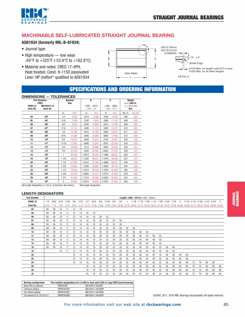
For more information visit our web site at rbcbearings.com
STRAIGHT JOURNAL BEARINGS
85
JOUR
NAL
BEAR
INGS
©2008, 2011, 2016 RBC Bearings Incorporated. All rights reserved.
MACHINABLE SELF-LUBRICATED STRAIGHT JOURNAL BEARINGAS81934 (formerly MIL-B-81934)• Journal type
• High temperature — low wear -65°F to +325°F (-53.9°C to +162.8°C)
• Material and notes: CRES 17-4PH, Heat treated, Cond. H-1150 passivatedLiner: HP Uniflon® qualified to AS81934
LENGTH DESIGNATORSPart Number Length: +000, -.010 in./ +00, -.25mm
PBHP( )C 1/4 9/32 5/16 11/32 3/8 7/16 1/2 9/16 5/8 11/16 3/4 7/8 1 1 1/8 1 1/4 1 3/8 1 1/2 1 5/8 1 3/4 1 7/8 2 2 1/8 2 1/4 2 3/8 2 1/2 2 3/4 3
Dash No. 6.35 7.14 7.94 8.73 9.52 11.11 12.70 14.29 15.88 17.46 19.05 22.22 25.40 28.58 31.75 34.92 38.10 41.28 44.45 47.62 50.80 53.98 57.15 60.32 63.50 69.85 76.20
04 08 09 10 11 12 14
05 08 09 10 11 12 14 16 18
06 08 09 10 11 12 14 16 18 20 22
07 08 09 10 11 12 14 16 18 20 22 24 28
08 08 09 10 11 12 14 16 18 20 22 24 28
09 08 09 10 11 12 14 16 18 20 22 24 28 32 36
10 08 09 10 11 12 14 16 18 20 22 24 28 32 36 40 44
11 08 09 10 11 12 14 16 18 20 22 24 28 32 36 40 44 48 52
12 08 09 10 11 12 14 16 18 20 22 24 28 32 36 40 44 48 52
14 08 09 10 11 12 14 16 18 20 22 24 28 32 36 40 44 48 52
16 08 09 10 11 12 14 16 18 20 22 24 28 32 36 40 44 48 52 56 60
18 10 11 12 14 16 18 20 22 24 28 32 36 40 44 48 52 56 60
20 12 14 16 18 20 22 24 28 32 36 40 44 48 52 56 60 64 68
22 12 14 16 18 20 22 24 28 32 36 40 44 48 52 56 60 64 68
24 12 14 16 18 20 22 24 28 32 36 40 44 48 52 56 60 64 68 72 76 80 88
26 16 18 20 22 24 28 32 36 40 44 48 52 56 60 64 68 72 76 80 88 96
28 16 18 20 22 24 28 32 36 40 44 48 52 56 60 64 68 72 76 80 88 96
32 16 18 20 22 24 28 32 36 40 44 48 52 56 60 64 68 72 76 80 88 96
Bearing configuration Part number designations for a 0.250 in. bore and 0.250 in. long CRES journal bearingBase P/N (no options) PBHP0C08 M81934/1-04C008Cadmium plating PBHP04C08C M81934/1-04C008PZinc Nickel plating PBHP04C08Z M81934/1-04C008E1st oversize O.D. (0.010 in.) PBHP04C08Q M81934/1-04C008T
SPECIFICATIONS AND ORDERING INFORMATION
B D
L
(See Table)
.030 (0.76mm)
.020 (0.51mm)
Break Edge
15° ± 2°
0.010 Max. for length code 012 or less; 0.025 Max. for all other lengths
CHAMFER
DETAIL A
A
DIMENSIONS — TOLERANCES
in. mm in. mm in. mm lbs.-in kg-mm
04 -04† 1/4 6.350 .2515 6.388 .3760 9.550 .006 .003
05 -05† 5/16 7.938 .3140 7.976 .4386 11.140 .008 .004
06 -06† 3/8 9.525 .3765 9.563 .5012 12.730 .009 .004
07 -07† 7/16 11.112 .4390 11.151 .5638 14.321 .010 .005
08 -08† 1/2 12.700 .5015 12.738 .6265 15.913 .011 .005
09 -09† 9/16 14.288 .5640 14.326 .6892 17.506 .013 .006
10 -10† 5/8 15.875 .6265 15.913 .8142 20.681 .022 .010
11 -11† 11/16 17.462 .6890 17.501 .8767 22.268 .023 .010
12 -12† 3/4 19.050 .7515 19.088 .9393 23.858 .025 .011
14 -14† 7/8 22.225 .8765 22.263 1.0645 27.038 .029 .013
16 -16† 1 25.400 1.0015 25.438 1.1898 38.221 .033 .015
18 -18† 1 1/8 28.575 1.1265 28.613 1.3148 33.396 .037 .017
20 -20† 1 1/4 31.750 1.2515 31.788 1.4398 38.571 .040 .018
22 -22† 1 3/8 34.925 1.3765 34.963 1.5648 39.746 .044 .020
24 -24† 1 1/2 38.100 1.5015 38.138 1.7523 44.508 .065 .029
26 -26† 1 5/8 41.275 1.6265 41.313 1.8773 47.683 .070 .032
28 -28† 1 3/4 44.450 1.7515 44.488 2.0023 50.858 .075 .034
32 -32† 2 50.800 2.0015 50.838 2.2523 57.208 .085 .039
Add length designation in 1/32 in. increments. (See below.) †Add length designation.
Weight L = 1.000 in.L = 25.4 mm
Ref.
D
+.000, - .0005 +.000, -.013
B
+.000, - .0010 +.000, -.25
NominalSize
Part NumbersCRES
PBHP( )C M81934/1( )CDash No. Dash No.
PB_073_097_8-30-16_Pln_079_103.qxd 8/30/16 11:09 AM Page 85
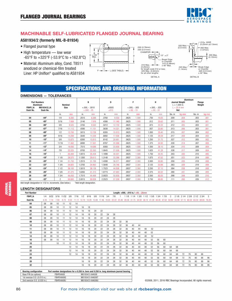
For more information visit our web site at rbcbearings.com
FLANGED JOURNAL BEARINGS
86
JOUR
NAL
BEAR
INGS
©2008, 2011, 2016 RBC Bearings Incorporated. All rights reserved.
DIMENSIONS — TOLERANCESAluminum
in. mm in. mm in. mm in. mm in. mm lbs.-in kg-mm lbs.-in kg-mm
04 -04† 1/4 6.350 .2515 6.388 .3760 9.550 .0625 1.588 .750 19.05 .009 .004 .003 .001
05 -05† 5/16 7.938 .3140 7.976 .4386 11.140 .0625 1.588 .812 20.62 .011 .005 .003 .001
06 -06† 3/8 9.525 .3765 9.563 .5012 12.730 .0625 1.588 .875 22.22 .012 .005 .003 .001
07 -07† 7/16 11.112 .4390 11.151 .5638 14.321 .0625 1.588 .937 23.80 .013 .006 .003 .001
08 -08† 1/2 12.700 .5015 12.738 .6265 15.913 .0625 1.588 1.000 25.40 .015 .007 .004 .002
09 -09† 9/16 14.288 .5640 14.326 .6892 17.506 .0625 1.588 1.125 28.58 .017 .008 .004 .002
10 -10† 5/8 15.875 .6265 15.913 .8142 20.681 .0625 1.588 1.250 31.75 .027 .012 .005 .002
11 -11† 11/16 17.462 .6890 17.501 .8767 22.268 .0625 1.588 1.375 34.92 .030 .014 .007 .003
12 -12† 3/4 19.050 .7515 19.088 .9393 23.858 .0625 1.588 1.500 38.10 .034 .015 .009 .004
14 -14† 7/8 22.225 .8765 22.263 1.0645 27.038 .0625 1.588 1.625 41.28 .038 .017 .009 .004
16 -16† 1 25.400 1.0015 25.438 1.1898 30.221 .0625 1.588 1.750 44.45 .043 .020 .010 .005
18 -18† 1 1/8 28.575 1.1265 28.613 1.3148 33.396 .0937 2.380 1.875 47.62 .051 .023 .014 .006
20 -20† 1 1/4 31.750 1.2515 31.788 1.4398 36.571 .0937 2.380 2.000 50.80 .058 .026 .018 .008
22 -22† 1 3/8 34.925 1.3765 34.963 1.5648 39.746 .0937 2.380 2.125 53.98 .063 .029 .019 .009
24 -24† 1 1/2 38.100 1.5015 38.138 1.7523 44.508 .0937 2.380 2.250 57.15 .084 .038 .018 .008
26 -26† 1 5/8 41.275 1.6265 41.313 1.8773 47.683 .0937 2.380 2.375 60.32 .090 .041 .020 .009
28 -28† 1 3/4 44.450 1.7515 44.488 2.0023 50.858 .0937 2.380 2.500 63.50 .098 .044 .023 .010
32 -32† 2 50.800 2.0015 50.838 2.2523 57.208 .0937 2.380 2.750 69.85 .111 .050 .026 .012
Add length designation in 1/32 in. increments. (See below.) †Add length designation.
FlangeWeight
Journal WeightL = 1.000 in.L = 25.4 mm
Ref.
H
+.000, - .020 +.00, -.51
F
+.000, - .005 +.00, -.13
D
±0005±013
B
+.000, - .0010 +.000, -.25
NominalSize
Part NumbersAluminum
FBHP( )A M81934/2( )ADash No. Dash No.
AS81934/2 (formerly MIL-B-81934)• Flanged journal type
• High temperature — low wear -65°F to +325°F (-53.9°C to +162.8°C)
• Material: Aluminum alloy, Cond. T8511anodized or chemical-film treatedLiner: HP Uniflon® qualified to AS81934
H
B
+ .100
Max.D
L (SEE TABLE)F
.030 (0.76mm)
.020 (0.51mm)
Break Edge or Chamfer.020 (0.51mm) x 45° Max.
15° ± 2°
CHAMFER
DETAIL A DETAIL B
AB
B.005 Max.(0.13mm)
.045 Max.(1.14mm)
.020 Max.(0.51mm)
F
.062 Max.(1.57mm)
Break Edge or Chamfer.015 (0.38mm) x 45° Max..010 Max.
(0.25mm) for length code 012 or less; .025 Max. (0.64mm) for all other lengths
.010± .005R(0.25mm ±0.13mm)
MACHINABLE SELF-LUBRICATED FLANGED JOURNAL BEARING
LENGTH DESIGNATORSPart Number Length: +000, -.010 in./ +00, -.25mm
FBHP( )A 1/4 9/32 5/16 11/32 3/8 7/16 1/2 9/16 5/8 11/16 3/4 7/8 1 1 1/8 1 1/4 1 3/8 1 1/2 1 5/8 1 3/4 1 7/8 2 2 1/8 2 1/4 2 3/8 2 1/2 2 3/4 3
Dash No. 6.35 7.14 7.94 8.73 9.52 11.11 12.70 14.29 15.88 17.46 19.05 22.22 25.40 28.58 31.75 34.92 38.10 41.28 44.45 47.62 50.80 53.98 57.15 60.32 63.50 69.85 76.20
04 08 09 10 11 12 14
05 08 09 10 11 12 14 16 18
06 08 09 10 11 12 14 16 18 20 22
07 08 09 10 11 12 14 16 18 20 22 24 28
08 08 09 10 11 12 14 16 18 20 22 24 28
09 08 09 10 11 12 14 16 18 20 22 24 28 32 36
10 08 09 10 11 12 14 16 18 20 22 24 28 32 36 40 44
11 08 09 10 11 12 14 16 18 20 22 24 28 32 36 40 44 48 52
12 08 09 10 11 12 14 16 18 20 22 24 28 32 38 40 44 48 52
14 08 09 10 11 12 14 16 18 20 22 24 28 32 36 40 44 48 52
16 08 09 10 11 12 14 16 18 20 22 24 28 32 36 40 44 48 52 56 60
18 10 11 12 14 16 18 20 22 24 28 32 36 40 44 48 52 56 60
20 12 14 16 18 20 22 24 28 32 36 40 44 48 52 56 60 64 68
22 12 14 16 18 20 22 24 28 32 36 40 44 48 52 56 60 64 68
24 12 14 16 18 20 22 24 28 32 36 40 44 48 52 56 60 64 68 72 76 80 88
26 16 18 20 22 24 28 32 36 40 44 48 52 56 60 64 68 72 76 80 88 96
28 16 18 20 22 24 28 32 36 40 44 48 52 56 60 64 68 72 76 80 88 96
32 16 18 20 22 24 28 32 36 40 44 48 52 56 60 64 68 72 76 80 88 96
SPECIFICATIONS AND ORDERING INFORMATION
Bearing configuration Part number designations for a 0.250 in. bore and 0.250 in. long aluminum journal bearingBase P/N (no options) FBHP04A08 M81934/2-04A0081st oversize O.D. (0.010 in.) FBHP04A08Q M81934/2-04A008T2nd oversize O.D. (0.020 in.) FBHP04A08U M81934/2-04A008U
PB_073_097_8-30-16_Pln_079_103.qxd 8/30/16 11:09 AM Page 86

For more information visit our web site at rbcbearings.com
FLANGED JOURNAL BEARINGS
87
JOUR
NAL
BEAR
INGS
©2008, 2011, 2016 RBC Bearings Incorporated. All rights reserved.
DIMENSIONS — TOLERANCESCRES
in. mm in. mm in. mm in. mm in. mm lbs.-in kg-mm lbs.-in kg-mm
04 -04† 1/4 6.350 .2515 6.388 .3760 9.550 .0625 1.588 .750 19.05 .009 .004 .003 .001
05 -05† 5/16 7.938 .3140 7.976 .4386 11.140 .0625 1.588 .812 20.62 .011 .005 .003 .001
06 -06† 3/8 9.525 .3765 9.563 .5012 12.730 .0625 1.588 .875 22.22 .012 .005 .003 .001
07 -07† 7/16 11.112 .4390 11.151 .5638 14.321 .0625 1.588 .937 23.80 .013 .006 .003 .001
08 -08† 1/2 12.700 .5015 12.738 .6265 15.913 .0625 1.588 1.000 25.40 .015 .007 .004 .002
09 -09† 9/16 14.288 .5640 14.326 .6892 17.506 .0625 1.588 1.125 28.58 .017 .008 .004 .002
10 -10† 5/8 15.875 .6265 15.913 .8142 20.681 .0625 1.588 1.250 31.75 .027 .012 .005 .002
11 -11† 11/16 17.462 .6890 17.501 .8767 22.268 .0625 1.588 1.375 34.92 .030 .014 .007 .003
12 -12† 3/4 19.050 .7515 19.088 .9393 23.858 .0625 1.588 1.500 38.10 .034 .015 .009 .004
14 -14† 7/8 22.225 .8765 22.263 1.0645 27.038 .0625 1.588 1.625 41.28 .038 .017 .009 .004
16 -16† 1 25.400 1.0015 25.438 1.1898 30.221 .0625 1.588 1.750 44.45 .043 .020 .010 .005
18 -18† 1 1/8 28.575 1.1265 28.613 1.3148 33.396 .0937 2.380 1.875 47.62 .051 .023 .014 .006
20 -20† 1 1/4 31.750 1.2515 31.788 1.4398 36.571 .0937 2.380 2.000 50.80 .058 .026 .018 .008
22 -22† 1 3/8 34.925 1.3765 34.963 1.5648 39.746 .0937 2.380 2.125 53.98 .063 .029 .019 .009
24 -24† 1 1/2 38.100 1.5015 38.138 1.7523 44.508 .0937 2.380 2.250 57.15 .084 .038 .018 .008
26 -26† 1 5/8 41.275 1.6265 41.313 1.8773 47.683 .0937 2.380 2.375 60.32 .090 .041 .020 .009
28 -28† 1 3/4 44.450 1.7515 44.488 2.0023 50.858 .0937 2.380 2.500 63.50 .098 .044 .023 .010
32 -32† 2 50.800 2.0015 50.838 2.2523 57.208 .0937 2.380 2.750 69.85 .111 .050 .026 .012
Add length designation in 1/32 in. increments. (See below.) †Add length designation.
FlangeWeight
Journal WeightL = 1.000 in.L = 25.4 mm
Ref.
H
+.000, - .020 +.00, -.51
F
+.000, - .005 +.00, -.13
D
+.000, - .0005 +.000, -.013
B
+.000, - .0010 +.000, -.25
NominalSize
Part NumbersCRES
FBHP( )C M81934/2( )CDash No. Dash No.
AS81934/2 (formerly MIL-B-81934)• Flanged journal type
• High temperature — low wear -65°F to +325°F. (-53.9°C to +162.8°C)
• Material: CRES 17-4PH, heat treated, Cond. H-1150 passivatedLiner: HP Uniflon® qualified to AS81934
MACHINABLE SELF-LUBRICATED FLANGED JOURNAL BEARING
LENGTH DESIGNATORSPart Number Length: +000, -.010 in./ +00, -.25mm
FBHP( )C 1/4 9/32 5/16 11/32 3/8 7/16 1/2 9/16 5/8 11/16 3/4 7/8 1 1 1/8 1 1/4 1 3/8 1 1/2 1 5/8 1 3/4 1 7/8 2 2 1/8 2 1/4 2 3/8 2 1/2 2 3/4 3
Dash No. 6.35 7.14 7.94 8.73 9.52 11.11 12.70 14.29 15.88 17.46 19.05 22.22 25.40 28.58 31.75 34.92 38.10 41.28 44.45 47.62 50.80 53.98 57.15 60.32 63.50 69.85 76.20
04 08 09 10 11 12 14
05 08 09 10 11 12 14 16 18
06 08 09 10 11 12 14 16 18 20 22
07 08 09 10 11 12 14 16 18 20 22 24 28
08 08 09 10 11 12 14 16 18 20 22 24 28
09 08 09 10 11 12 14 16 18 20 22 24 28 32 36
10 08 09 10 11 12 14 16 18 20 22 24 28 32 36 40 44
11 08 09 10 11 12 14 16 18 20 22 24 28 32 36 40 44 48 52
12 08 09 10 11 12 14 16 18 20 22 24 28 32 38 40 44 48 52
14 08 09 10 11 12 14 16 18 20 22 24 28 32 36 40 44 48 52
16 08 09 10 11 12 14 16 18 20 22 24 28 32 36 40 44 48 52 56 60
18 10 11 12 14 16 18 20 22 24 28 32 36 40 44 48 52 56 60
20 12 14 16 18 20 22 24 28 32 36 40 44 48 52 56 60 64 68
22 12 14 16 18 20 22 24 28 32 36 40 44 48 52 56 60 64 68
24 12 14 16 18 20 22 24 28 32 36 40 44 48 52 56 60 64 68 72 76 80 88
26 16 18 20 22 24 28 32 36 40 44 48 52 56 60 64 68 72 76 80 88 96
28 16 18 20 22 24 28 32 36 40 44 48 52 56 60 64 68 72 76 80 88 96
32 16 18 20 22 24 28 32 36 40 44 48 52 56 60 64 68 72 76 80 88 96
Bearing configuration Part number designations for a 0.250 in. bore and 0.250 in. long CRES journal bearingBase P/N (no options) FBHP04C08 M81934/2-04C008Cadmium plating FBHP04C08C M81934/2-04C008PZinc Nickel plating FBHP04C08Z M81934/2-04C008E1st oversize O.D. (0.010 in.) FBHP04C08Q M81934/2-04C008T2nd oversize O.D. (0.020 in.) FBHP04C08U M81934/2-04C008U
SPECIFICATIONS AND ORDERING INFORMATION
H
B
+ .100
Max.D
L (SEE TABLE)F
.030 (0.76mm)
.020 (0.51mm)
Break Edge or Chamfer.020 (0.51mm) x 45° Max.
15° ± 2°
CHAMFER
DETAIL A DETAIL B
AB
B.005 Max.(0.13mm)
.045 Max.(1.14mm)
.020 Max.(0.51mm)
F
.062 Max.(1.57mm)
Break Edge or Chamfer.015 (0.38mm) x 45° Max..010 Max.
(0.25mm) for length code 012 or less; .025 Max. (0.64mm) for all other lengths
.010± .005R(0.25mm ±0.13mm)
PB_073_097_8-30-16_Pln_079_103.qxd 8/30/16 11:09 AM Page 87

For more information visit our web site at rbcbearings.com
STRAIGHT JOURNAL BEARINGS
88
JOUR
NAL
BEAR
INGS
©2008, 2011, 2016 RBC Bearings Incorporated. All rights reserved.
• Journal type
• Low friction — low wear-65°F to +250°F (-54°C to +121°C)
• Material:CRES 17-4PH, heat treatedLiner: Dyflon® machinable
DYFLON® WATER RESISTANT SELF-LUBRICATED STRAIGHT JOURNAL BEARING
SPECIFICATIONS AND ORDERING INFORMATIONDIMENSIONS — TOLERANCES
in. mm in. mm in. mm lbs. kg
4 0.2525 6.414 0.3765 9.563 0.250 6.350 0.0043 0.0020 .0001 to .0011 in. .003 to .028 mm
5 0.3150 8.001 0.4390 11.151 0.312 7.925 0.0064 0.0029 .0001 to .0011 in. .003 to .028 mm
6 0.3775 9.589 0.5640 14.326 0.375 9.525 0.0146 0.0066 .0001 to .0011 in. .003 to .028 mm
7 0.4400 11.176 0.6265 15.913 0.437 11.100 0.0193 0.0088 .0001 to .0011 in. .003 to .028 mm
8 0.5025 12.764 0.6890 17.501 0.500 12.700 0.0247 0.0112 .0001 to .0011 in. .003 to .028 mm
9 0.5650 14.351 0.7515 19.088 0.562 14.275 0.0307 0.0139 .0003 to .0015 in. .008 to .038 mm
10 0.6275 15.939 0.8765 22.263 0.625 15.875 0.0522 0.0237 .0003 to .0015 in. .008 to .038 mm
12 0.7535 19.139 1.0020 25.451 0.750 19.050 0.0729 0.0331 .0003 to .0015 in. .008 to .038 mm
14 0.8785 22.314 1.1270 28.626 0.875 22.225 0.0971 0.0441 .0003 to .0015 in. .008 to .038 mm
16 1.0035 25.489 1.2520 31.801 1.000 25.400 0.1248 0.0566 .0003 to .0015 in. .008 to .038 mm
18 1.1285 28.664 1.3770 34.976 1.125 28.575 0.1560 0.0707 .0003 to .0017 in. .008 to .043 mm
20 1.2535 31.839 1.5020 38.151 1.250 31.750 0.1906 0.0864 .0003 to .0017 in. .008 to .043 mm
22 1.3800 35.052 1.6275 41.339 1.375 34.925 0.2279 0.1034 .0003 to .0017 in. .008 to .043 mm
24 1.5050 38.227 1.7525 44.514 1.500 38.100 0.2692 0.1221 .0003 to .0017 in. .008 to .043 mm
26 1.6300 41.402 1.8775 47.689 1.625 41.275 0.3140 0.1424 .0003 to .0017 in. .008 to .043 mm
28 1.7750 45.085 2.0025 50.864 1.750 44.450 0.3345 0.1517 .0003 to .0017 in. .008 to .043 mm
30 1.8800 47.752 2.1275 54.039 1.875 47.625 0.4140 0.1878 .0005 to .0020 in .013 to .051 mm
32 2.0050 50.927 2.3775 60.389 2.000 50.800 0.7291 0.3307 .0005 to .0020 in .013 to .051 mm
36 2.2550 57.277 2.6275 66.739 2.250 57.150 0.9138 0.4145 .0005 to .0020 in .013 to .051 mm
40 2.5060 63.652 2.8775 73.089 2.500 63.500 1.1164 0.5064 .0005 to .0020 in .013 to .051 mm
44 2.7560 70.002 3.1275 79.439 2.750 69.850 1.3421 0.6087 .0005 to .0020 in .013 to .051 mm
48 3.0060 76.352 3.5025 88.964 3.000 76.200 2.1680 0.9834 .0005 to .0020 in .013 to .051 mm
52 3.2560 82.702 *3.7525 95.314 3.250 82.550 2.5290 1.1471 .0007 to .0025 in. .018 to .064 mm
56 3.5060 89.052 *4.0025 101.664 3.500 88.900 2.9178 1.3235 .0007 to .0025 in. .018 to .064 mm
60 3.7560 95.402 *4.2525 108.014 3.750 95.250 3.3343 1.5124 .0007 to .0025 in. .018 to .064 mm
64 4.0060 101.752 *4.5025 114.364 4.000 101.600 3.7786 1.7139 .0007 to .0025 in. .018 to .064 mm
68 4.2560 108.102 *4.7525 120.714 4.250 107.950 4.2506 1.9280 .0007 to .0025 in. .018 to .064 mm
72 *4.5070 114.478 **5.0031 127.079 4.500 114.300 4.7474 2.1534 .0007 to .0030 in. .018 to .076 mm
76 *4.7570 120.828 **5.2531 133.429 4.750 120.650 5.2745 2.3925 .0007 to .0030 in. .018 to .076 mm
80 *5.0070 127.178 **5.5031 139.779 5.000 127.000 5.8294 2.6441 .0007 to .0030 in. .018 to .076 mm
88 *5.5070 139.878 **6.0031 152.479 5.500 139.700 7.0223 3.1852 .0007 to .0030 in. .018 to .076 mm
96 *6.0070 152.578 **6.5031 165.179 6.000 152.400 8.3261 3.7766 .0007 to .0030 in. .018 to .076 mm
104 *6.5070 165.278 **7.0031 177.879 6.500 165.100 9.7408 4.4183 .0007 to .0030 in. .018 to .076 mm
112 *7.0070 177.978 **7.5031 108.579 7.000 177.800 11.2664 5.1103 .0007 to .0030 in. .018 to .076 mm
120 *7.5070 190.678 **8.0031 203.279 7.500 190.500 12.9030 5.8527 .0007 to .0030 in. .018 to .076 mm
128 *8.0070 203.378 **8.5031 251.979 8.000 203.200 14.6504 6.6453 .0007 to .0030 in. .018 to .076 mm
Available Journal Material options: 300 series stainless steel for salt water immersion, or aluminum for light weight.
*+.000, - .0008 +.000, -.020
**+.000, - .0010 +.000, -.025
*+.000, - .0020+.000, -.051
Housing Bore Recommended Interference
Weight
Approx.
L
+.000, - .005 +.000, -.13
D
+.000, - .0005 +.000, -.013
B
+.000, - .0010 +.000, -.025
Part NumberDBS-xx-030
B D
L
.030 (0.76mm)
MAX both ends
CHAMFER
Radius
.030 (0.76mm)
MAX both ends
DETAIL A
A
DYFLON®
LINER
PB_073_097_8-30-16_Pln_079_103.qxd 8/30/16 11:09 AM Page 88

For more information visit our web site at rbcbearings.com
FLANGED JOURNAL BEARINGS
89
JOUR
NAL
BEAR
INGS
©2008, 2011, 2016 RBC Bearings Incorporated. All rights reserved.
DYFLON® WATER RESISTANT SELF-LUBRICATED FLANGED JOURNAL BEARING• Flanged journal type
• Low friction — low wear-65°F to +250°F (-54°C to +121°C)
• Material:CRES 17-4PH, heat treatedLiner: Dyflon® machinable
SPECIFICATIONS AND ORDERING INFORMATIONDIMENSIONS — TOLERANCES
in. mm in. mm in. mm in. mm in. mm lbs. kg
4 0.2525 6.414 0.3765 9.563 0.375 9.525 0.125 3.175 0.500 12.700 0.0091 0.0041 .0001 to .0011 in. .003 to .028 mm
5 0.3150 8.001 0.4390 11.151 0.437 11.100 0.125 3.175 0.562 14.275 0.0120 0.0055 .0001 to .0011 in. .003 to .028 mm
6 0.3775 9.589 0.5640 14.326 0.500 12.700 0.125 3.175 0.625 15.875 0.0210 0.0095 .0001 to .0011 in. .003 to .028 mm
7 0.4400 11.176 0.6265 15.913 0.562 14.275 0.125 3.175 0.750 19.050 0.0288 0.0131 .0001 to .0011 in. .003 to .028 mm
8 0.5025 12.764 0.6890 17.501 0.625 15.875 0.125 3.175 0.875 22.225 0.0379 0.0172 .0001 to .0011 in. .003 to .028 mm
9 0.5650 14.351 0.7515 19.088 0.687 17.450 0.125 3.175 1.062 26.975 0.0515 0.0234 .0003 to .0015 in. .008 to .038 mm
10 0.6275 15.939 0.8765 22.263 0.750 19.050 0.125 3.175 1.188 30.175 0.0784 0.0356 .0003 to .0015 in. .008 to .038 mm
12 0.7535 19.139 1.0020 25.451 0.875 22.225 0.125 3.175 1.312 33.325 0.1027 0.0466 .0003 to .0015 in. .008 to .038 mm
14 0.8785 22.314 1.1270 28.626 1.000 25.400 0.125 3.175 1.500 38.100 0.1353 0.0614 .0003 to .0015 in. .008 to .038 mm
16 1.0035 25.489 1.2520 31.801 1.187 30.150 0.125 3.175 1.750 44.450 0.1856 0.0842 .0003 to .0015 in. .008 to .038 mm
18 1.1285 28.664 1.3770 34.976 1.312 33.325 0.187 4.750 1.890 48.006 0.2472 0.1121 .0003 to .0017 in. .008 to .043 mm
20 1.2535 31.839 1.5020 38.151 1.437 36.500 0.187 4.750 2.015 51.181 0.2894 0.1313 .0003 to .0017 in. .008 to .043 mm
22 1.3800 35.052 1.6275 41.339 1.562 39.675 0.187 4.750 2.140 54.356 0.3341 0.1515 .0003 to .0017 in. .008 to .043 mm
24 1.5050 38.227 1.7525 44.514 1.687 42.850 0.187 4.750 2.265 57.531 0.3830 0.1737 .0003 to .0017 in. .008 to .043 mm
26 1.6300 41.402 1.8775 47.689 1.812 46.025 0.187 4.750 2.390 60.706 0.4353 0.1975 .0003 to .0017 in. .008 to .043 mm
28 1.7750 45.085 2.0025 50.864 2.000 50.800 0.187 4.750 2.515 63.881 0.4726 0.2144 .0003 to .0017 in. .008 to .043 mm
30 1.8800 47.752 2.1275 54.039 2.215 56.261 0.187 4.750 2.640 67.056 0.5841 0.2650 .0005 to .0020 in. .013 to .051 mm
32 2.0050 50.927 2.3775 60.389 2.375 60.325 0.187 4.750 3.000 76.200 0.9954 0.4515 .0005 to .0020 in. .013 to .051 mm
36 2.2550 57.277 2.6275 66.739 2.625 66.675 0.187 4.750 3.250 82.550 1.2077 0.5478 .0005 to .0020 in. .013 to .051 mm
40 2.5060 63.652 2.8775 73.089 2.875 73.025 0.187 4.750 3.500 88.900 1.4375 0.6520 .0005 to .0020 in. .013 to .051 mm
44 2.7560 70.002 3.1275 79.439 3.125 79.375 0.187 4.750 3.750 95.250 1.6906 0.7669 .0005 to .0020 in. .013 to .051 mm
48 3.0060 76.352 3.5025 88.964 3.375 85.725 0.187 4.750 4.000 101.600 2.5804 1.1704 .0005 to .0020 in. .013 to .051 mm
52 3.2560 82.702 *3.7525 95.314 3.625 92.075 0.187 4.750 4.250 107.950 2.9716 1.3479 .0007 to .0025 in. .018 to .064 mm
56 3.5060 89.052 *4.0025 101.664 3.875 98.425 0.187 4.750 4.500 114.300 3.3905 1.5379 .0007 to .0025 in. .018 to .064 mm
60 3.7560 95.402 *4.2525 108.014 4.125 104.775 0.187 4.750 4.750 120.650 3.8372 1.7405 .0007 to .0025 in. .018 to .064 mm
64 4.0060 101.752 *4.5025 114.364 4.375 111.125 0.187 4.750 5.000 127.000 4.3117 1.9557 .0007 to .0025 in. .018 to .064 mm
68 4.2560 108.102 *4.7525 120.714 4.625 117.475 0.187 4.750 5.250 133.350 4.8139 2.1835 .0007 to .0025 in. .018 to .064 mm
72 *4.5070 114.478 **5.0031 127.079 4.875 123.825 0.250 6.350 5.500 139.700 5.4141 2.4558 .0007 to .0030 in. .018 to .076 mm
76 *4.7570 120.828 **5.2531 133.429 5.125 130.175 0.250 6.350 5.750 146.050 5.9749 2.7102 .0007 to .0030 in. .018 to .076 mm
80 *5.0070 127.178 **5.5031 139.779 5.375 136.525 0.250 6.350 6.000 152.400 6.5635 2.9771 .0007 to .0030 in. .018 to .076 mm
88 *5.5070 139.878 **6.0031 152.479 5.875 149.225 0.250 6.350 6.500 165.100 7.8237 3.5487 .0007 to .0030 in. .018 to .076 mm
96 *6.0070 152.578 **6.5031 165.179 6.375 161.925 0.250 6.350 7.000 177.800 9.1948 4.1707 .0007 to .0030 in. .018 to .076 mm
104 *6.5070 165.278 **7.0031 177.879 6.875 174.625 0.250 6.350 7.500 190.500 10.6769 4.8429 .0007 to .0030 in. .018 to .076 mm
112 *7.0070 177.978 **7.5031 108.579 7.375 187.325 0.250 6.350 8.000 203.200 12.2698 5.5655 .0007 to .0030 in. .018 to .076 mm
120 *7.5070 190.678 **8.0031 203.279 7.875 200.025 0.250 6.350 8.500 215.900 13.9736 6.3383 .0007 to .0030 in. .018 to .076 mm
128 *8.0070 203.378 **8.5031 251.979 8.375 212.725 0.250 6.350 9.000 228.600 15.7884 7.1615 .0007 to .0030 in. .018 to .076 mm
Available Journal Material options: 300 series stainless steel for salt water immersion, or aluminum for light weight.
H
+.005, - .005 +.13, -.13
F
+.005, - .005 +.13, -.13
*+.000, - .0008 +.000, -.020
**+.000, - .0010 +.000, -.025
*+.000, - .0020+.000, -.051
Housing Bore Recommended Interference
Weight
Approx.
L
+.000, - .005 +.000, -.13
D
+.000, - .0005 +.000, -.013
B
+.000, - .0010 +.000, -.025
Part NumberDBSF-xx-130
H D
F
A
B
L
.030 (0.76mm)MAX both ends
CHAMFER
Radius.030 (0.76mm)MAX both ends
Radius .030 (0.76mm)
DETAIL A
DYFLON®
LINER
PB_073_097_8-30-16_Pln_079_103.qxd 8/30/16 11:09 AM Page 89
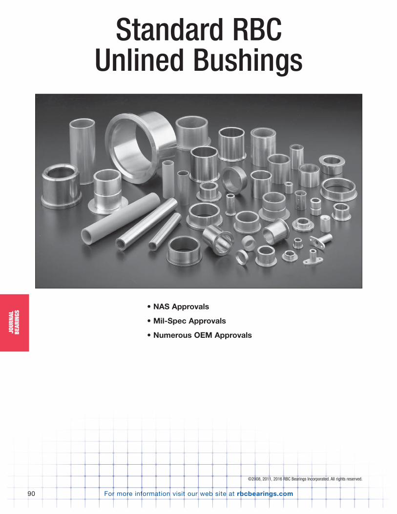
For more information visit our web site at rbcbearings.com90
JOUR
NAL
BEAR
INGS
Standard RBC Unlined Bushings
• NAS Approvals
• Mil-Spec Approvals
• Numerous OEM Approvals
©2008, 2011, 2016 RBC Bearings Incorporated. All rights reserved.
PB_073_097_8-30-16_Pln_079_103.qxd 8/30/16 11:09 AM Page 90
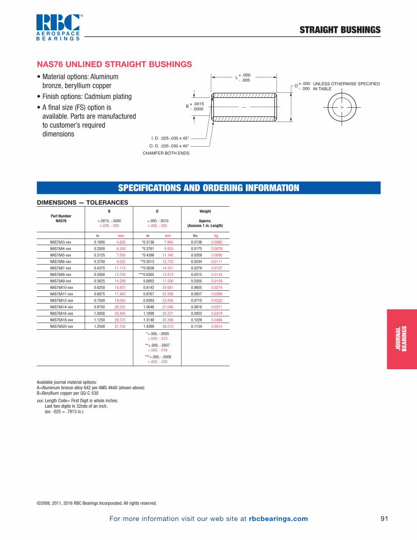
For more information visit our web site at rbcbearings.com
STRAIGHT BUSHINGS
91
JOUR
NAL
BEAR
INGS
©2008, 2011, 2016 RBC Bearings Incorporated. All rights reserved.
• Material options: Aluminumbronze, beryllium copper
• Finish options: Cadmium plating
• A final size (FS) option isavailable. Parts are manufacturedto customer’s requireddimensions
NAS76 UNLINED STRAIGHT BUSHINGS
DUNLESS OTHERWISE SPECIFIED
IN TABLE
+ .000
- .000
L+ .000
- .005
B+ .0015
- .0000
I. D. .025-.035 x 45°
O. D. .025-.035 x 45°
CHAMFER BOTH ENDS
SPECIFICATIONS AND ORDERING INFORMATIONDIMENSIONS — TOLERANCES
in. mm in. mm lbs. kg
NAS76A3-xxx 0.1900 4.826 *0.3136 7.965 0.0138 0.0062
NAS76A4-xxx 0.2500 6.350 *0.3761 9.553 0.0175 0.0079
NAS76A5-xxx 0.3125 7.938 *0.4386 11.140 0.0209 0.0095
NAS76A6-xxx 0.3750 9.525 **0.5013 12.733 0.0244 0.0111
NAS76A7-xxx 0.4375 11.113 **0.5638 14.321 0.0279 0.0127
NAS76A8-xxx 0.5000 12.700 ***0.6265 15.913 0.0315 0.0143
NAS76A9-xxx 0.5625 14.288 0.6892 17.506 0.0350 0.0159
NAS76A10-xxx 0.6250 15.875 0.8142 20.681 0.0605 0.0274
NAS76A11-xxx 0.6875 17.463 0.8767 22.268 0.0657 0.0298
NAS76A12-xxx 0.7500 19.050 0.9393 23.858 0.0710 0.0322
NAS76A14-xxx 0.8750 22.225 1.0648 27.046 0.0818 0.0371
NAS76A16-xxx 1.0000 25.400 1.1898 30.221 0.0923 0.0419
NAS76A18-xxx 1.1250 28.575 1.3148 33.396 0.1028 0.0466
NAS76A20-xxx 1.2500 31.750 1.4399 36.573 0.1134 0.0514
*+.000, -.0005 +.000, -.013
**+.000, -.0007 +.000, -.018
***+.000, -.0008 +.000, -.020
Weight
Approx.(Assume 1 in. Length)
D
+.000, -.0010 +.000, -.025
B
+.0015, -.0000 +.038, -.000
Part NumberNAS76
Available journal material options:A=Aluminum bronze alloy 642 per AMS 4640 (shown above)B=Beryllium copper per QQ-C-530
xxx: Length Code= First Digit in whole inches.Last two digits in 32nds of an inch.(ex: -025 = .7813 in.)
PB_073_097_8-30-16_Pln_079_103.qxd 8/30/16 11:09 AM Page 91
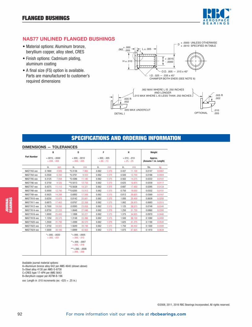
For more information visit our web site at rbcbearings.com
FLANGED BUSHINGS
92
JOUR
NAL
BEAR
INGS
©2008, 2011, 2016 RBC Bearings Incorporated. All rights reserved.
• Material options: Aluminum bronze,beryllium copper, alloy steel, CRES
• Finish options: Cadmium plating,aluminum coating
• A final size (FS) option is available. Parts are manufactured to customer’srequired dimensions
NAS77 UNLINED FLANGED BUSHINGS
+ .000
- .005
H ± .010
L ± .005
O.D. .005 — .015 x 45°
+ .0000 UNLESS OTHERWISE
+ .0010 SPECIFIED IN TABLE
I.D. .025 — .035 x 45°
CHAMFER BOTH ENDS (SEE NOTE 6)
.062 MAX WHERE L IS .250 INCHES
AND LONGER
.015 MAX WHERE L IS LESS THAN .250 INCHES
.062
+ .0015
- .0000B
D
.005 R
.002
.010
.005
.005 R
.002
OPTIONAL
.005 MAX UNDERCUT
SPECIFICATIONS AND ORDERING INFORMATIONDIMENSIONS — TOLERANCES
in. mm in. mm in. mm in. mm lbs. kg
NAS77A3-xxx 0.1900 4.826 *0.3136 7.965 0.062 1.575 0.437 11.100 0.0147 0.0067
NAS77A4-xxx 0.2500 6.350 *0.3761 9.553 0.062 1.575 0.500 12.700 0.0186 0.0084
NAS77A5-xxx 0.3125 7.938 *0.4386 11.140 0.062 1.575 0.562 14.275 0.0222 0.0101
NAS77A6-xxx 0.3750 9.525 **0.5013 12.733 0.062 1.575 0.625 15.875 0.0259 0.0117
NAS77A7-xxx 0.4375 11.113 **0.5638 14.321 0.062 1.575 0.687 17.450 0.0295 0.0134
NAS77A8-xxx 0.5000 12.700 ***0.6265 15.913 0.062 1.575 0.750 19.050 0.0332 0.0151
NAS77A9-xxx 0.5625 14.288 0.6892 17.506 0.062 1.575 0.812 20.625 0.0369 0.0167
NAS77A10-xxx 0.6250 15.875 0.8142 20.681 0.062 1.575 1.000 25.400 0.0639 0.0290
NAS77A11-xxx 0.6875 17.463 0.8767 22.268 0.062 1.575 1.062 26.975 0.0693 0.0315
NAS77A12-xxx 0.7500 19.050 0.9393 23.858 0.062 1.575 1.125 28.575 0.0749 0.0340
NAS77A14-xxx 0.8750 22.225 1.0648 27.046 0.062 1.575 1.250 31.750 0.0860 0.0390
NAS77A16-xxx 1.0000 25.400 1.1898 30.221 0.062 1.575 1.375 34.925 0.0970 0.0440
NAS77A18-xxx 1.1250 28.575 1.3148 33.396 0.062 1.575 1.500 38.100 0.1080 0.0490
NAS77A20-xxx 1.2500 31.750 1.4399 36.573 0.062 1.575 1.625 41.275 0.1190 0.0540
NAS77A22-xxx 1.3750 34.925 1.5649 39.748 0.062 1.575 1.750 44.450 0.1300 0.0590
NAS77A24-xxx 1.5000 38.100 1.6899 42.923 0.062 1.575 1.875 47.625 0.1410 0.0639
Available journal material options:A=Aluminum bronze alloy 642 per AMS 4640 (shown above)S=Steel alloy 4130 per AMS-S-6758C=CRES type 17-4PH per AMS 5643B=Beryllium copper per ASTM-B-196
xxx: Length in .010 increments (ex: -025 = .25 in.)
H
+.010, -.010 +.25, -.25
F
+.000, -.005 +.00, -.13
*+.000, -.0005 +.000, -.013
**+.000, -.0007 +.000, -.018
***+.000, -.0008 +.000, -.020
*+.000, -.0020+.000, -.051
Weight
Approx.(Assume 1 in. Length)
D
+.000, -.0010 +.000, -.025
B
+.0015, -.0000 +.038, -.000
Part Number
PB_073_097_8-30-16_Pln_079_103.qxd 8/30/16 11:09 AM Page 92

For more information visit our web site at rbcbearings.com
STRAIGHT BUSHINGS
93
JOUR
NAL
BEAR
INGS
©2008, 2011, 2016 RBC Bearings Incorporated. All rights reserved.
• Material options: CRES, alloy steel,aluminum bronze, beryllium copper
• Finish options: Cadmium plating, zincnickel plating, IVD aluminum coating
• A final size (FS) option is available. Parts are manufactured to customer’srequired dimensions
MS14237 UNLINED STRAIGHT BUSHINGS
PART MARKING
IN THIS AREA
L+ .000
- .005
.015
.005
45° ±5° (TYP)
(TYP)
D Ø B Ø
.020
.010x 45° ±5°
CHAMFER BOTH ENDS I.D.
DIMENSIONS — TOLERANCES
in. mm in. mm lbs. kg
MS14237C03-xxx 0.1770 4.496 0.3142 7.981 0.0149 0.0068 .0004/.0017 in. .003/.028 mm
MS14237C04-xxx *0.2350 5.969 0.3767 9.568 0.0192 0.0087 .0004/.0017 in. .003/.028 mm
MS14237C05-xxx *0.2990 7.595 0.4393 11.158 0.0229 0.0104 .0005/.0018 in. .013/.046 mm
MS14237C06-xxx *0.3560 9.042 *0.5020 12.751 0.0277 0.0126 .0005/.0020 in. .013/.051 mm
MS14237C07-xxx 0.4210 10.693 *0.5646 14.341 0.0313 0.0142 .0005/.0021 in. .013/.053 mm
MS14237C08-xxx 0.4830 12.268 **0.6272 15.931 0.0354 0.0161 .0005/.0022 in. .013/.056 mm
MS14237C10-xxx 0.6080 15.443 ***0.8150 20.701 0.0655 0.0297 .0006/.0025 in. .015/.064 mm
MS14237C12-xxx **0.7320 18.593 ***0.9400 23.876 0.0773 0.0351 .0006/.0025 in. .015/.064 mm
MS14237C14-xxx **0.8570 21.768 ***1.0651 27.054 0.0889 0.0403 .0006/.0026 in. .015/.066 mm
MS14237C16-xxx **0.9820 24.943 ***1.1901 30.229 0.1005 0.0456 .0006/.0026 in. .015/.066 mm
MS14237C18-xxx **1.1070 28.118 ***1.3151 33.404 0.1120 0.0508 .0006/.0026 in. .015/.066 mm
MS14237C20-xxx **1.2320 31.293 ***1.4401 36.579 0.1236 0.0561 .0006/.0026 in. .015/.066 mm
Available journal material options:C=CRES 17-4PH per AMS 5643 (shown above)S=Steel alloy 4130 per Mil-S-6758A=Aluminum nickel bronze per AMS 4640B=Beryllium copper per QQ-C-530
xxx: Length in .010 increments (ex: -025 = .25 in.)
Interference Fit
(Ref.)
*+.000, -.0007 +.000, -.020
**+.000, -.0008 +.000, -.025
***+.000, -.0010 +.000, -.025
*+.008, -.000+.200, -.000
Weight
Approx.(Assume 1 in. Length)
D
+.000, -.0005 +.000, -.013
B
+.007, -.000 +.180, -.000
Part Number
SPECIFICATIONS AND ORDERING INFORMATION
PB_073_097_8-30-16_Pln_079_103.qxd 8/30/16 11:09 AM Page 93
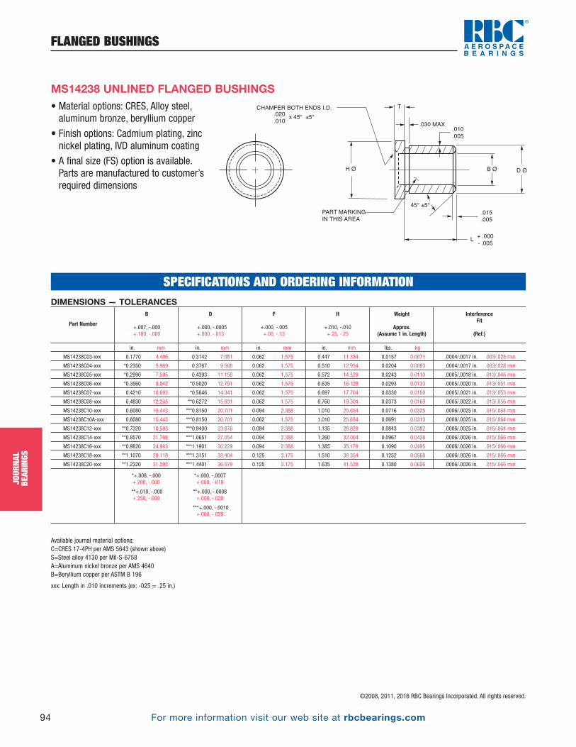
For more information visit our web site at rbcbearings.com
FLANGED BUSHINGS
94
JOUR
NAL
BEAR
INGS
©2008, 2011, 2016 RBC Bearings Incorporated. All rights reserved.
• Material options: CRES, Alloy steel,aluminum bronze, beryllium copper
• Finish options: Cadmium plating, zincnickel plating, IVD aluminum coating
• A final size (FS) option is available. Parts are manufactured to customer’srequired dimensions
MS14238 UNLINED FLANGED BUSHINGS
PART MARKING
IN THIS AREA
L
.015
.005
.010
.005
.030 MAX
D Ø
T
+ .000
- .005
45° ±5°
H Ø
.020
.010x 45° ±5°
CHAMFER BOTH ENDS I.D.
B Ø
SPECIFICATIONS AND ORDERING INFORMATIONDIMENSIONS — TOLERANCES
in. mm in. mm in. mm in. mm lbs. kg
MS14238C03-xxx 0.1770 4.496 0.3142 7.981 0.062 1.575 0.447 11.354 0.0157 0.0071 .0004/.0017 in. .003/.028 mm
MS14238C04-xxx *0.2350 5.969 0.3767 9.568 0.062 1.575 0.510 12.954 0.0204 0.0093 .0004/.0017 in. .003/.028 mm
MS14238C05-xxx *0.2990 7.595 0.4393 11.158 0.062 1.575 0.572 14.529 0.0243 0.0110 .0005/.0018 in. .013/.046 mm
MS14238C06-xxx *0.3560 9.042 *0.5020 12.751 0.062 1.575 0.635 16.129 0.0293 0.0133 .0005/.0020 in. .013/.051 mm
MS14238C07-xxx 0.4210 10.693 *0.5646 14.341 0.062 1.575 0.697 17.704 0.0330 0.0150 .0005/.0021 in. .013/.053 mm
MS14238C08-xxx 0.4830 12.268 **0.6272 15.931 0.062 1.575 0.760 19.304 0.0373 0.0169 .0005/.0022 in. .013/.056 mm
MS14238C10-xxx 0.6080 15.443 ***0.8150 20.701 0.094 2.388 1.010 25.654 0.0716 0.0325 .0006/.0025 in. .015/.064 mm
MS14238C10A-xxx 0.6080 15.443 ***0.8150 20.701 0.062 1.575 1.010 25.654 0.0691 0.0313 .0006/.0025 in. .015/.064 mm
MS14238C12-xxx **0.7320 18.593 ***0.9400 23.876 0.094 2.388 1.135 28.829 0.0843 0.0382 .0006/.0025 in. .015/.064 mm
MS14238C14-xxx **0.8570 21.768 ***1.0651 27.054 0.094 2.388 1.260 32.004 0.0967 0.0438 .0006/.0026 in. .015/.066 mm
MS14238C16-xxx **0.9820 24.943 ***1.1901 30.229 0.094 2.388 1.385 35.179 0.1090 0.0495 .0006/.0026 in. .015/.066 mm
MS14238C18-xxx **1.1070 28.118 ***1.3151 33.404 0.125 3.175 1.510 38.354 0.1252 0.0568 .0006/.0026 in. .015/.066 mm
MS14238C20-xxx **1.2320 31.293 ***1.4401 36.579 0.125 3.175 1.635 41.529 0.1380 0.0626 .0006/.0026 in. .015/.066 mm
Available journal material options:C=CRES 17-4PH per AMS 5643 (shown above)S=Steel alloy 4130 per Mil-S-6758A=Aluminum nickel bronze per AMS 4640B=Beryllium copper per ASTM B 196
xxx: Length in .010 increments (ex: -025 = .25 in.)
F
+.000, -.005 +.00, -.13
H
+.010, -.010 +.25, -.25
Interference Fit
(Ref.)
*+.000, -.0007 +.000, -.018
**+.000, -.0008 +.000, -.020
***+.000, -.0010 +.000, -.025
*+.008, -.000+.200, -.000
**+.010, -.000+.250, -.000
Weight
Approx.(Assume 1 in. Length)
D
+.000, -.0005 +.000, -.013
B
+.007, -.000 +.180, -.000
Part Number
PB_073_097_8-30-16_Pln_079_103.qxd 8/30/16 11:09 AM Page 94
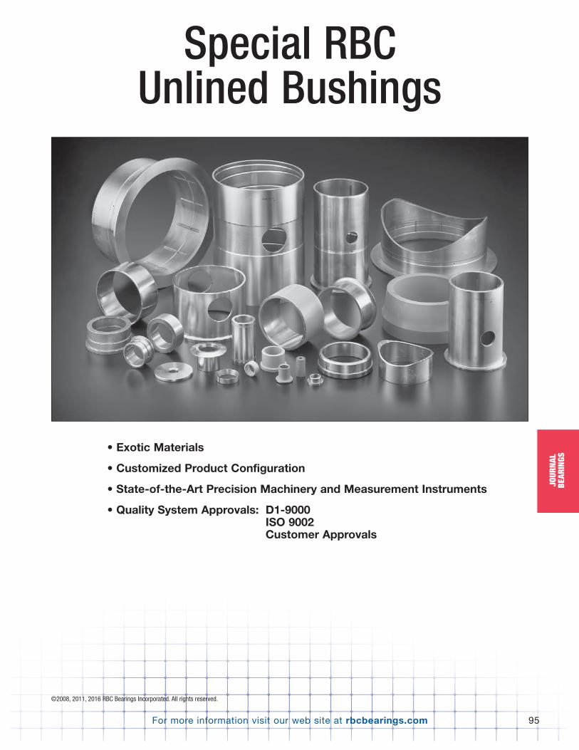
For more information visit our web site at rbcbearings.com
Special RBC Unlined Bushings
95
JOUR
NAL
BEAR
INGS
• Exotic Materials
• Customized Product Configuration
• State-of-the-Art Precision Machinery and Measurement Instruments
• Quality System Approvals: D1-9000ISO 9002Customer Approvals
©2008, 2011, 2016 RBC Bearings Incorporated. All rights reserved.
PB_073_097_8-30-16_Pln_079_103.qxd 8/30/16 11:09 AM Page 95
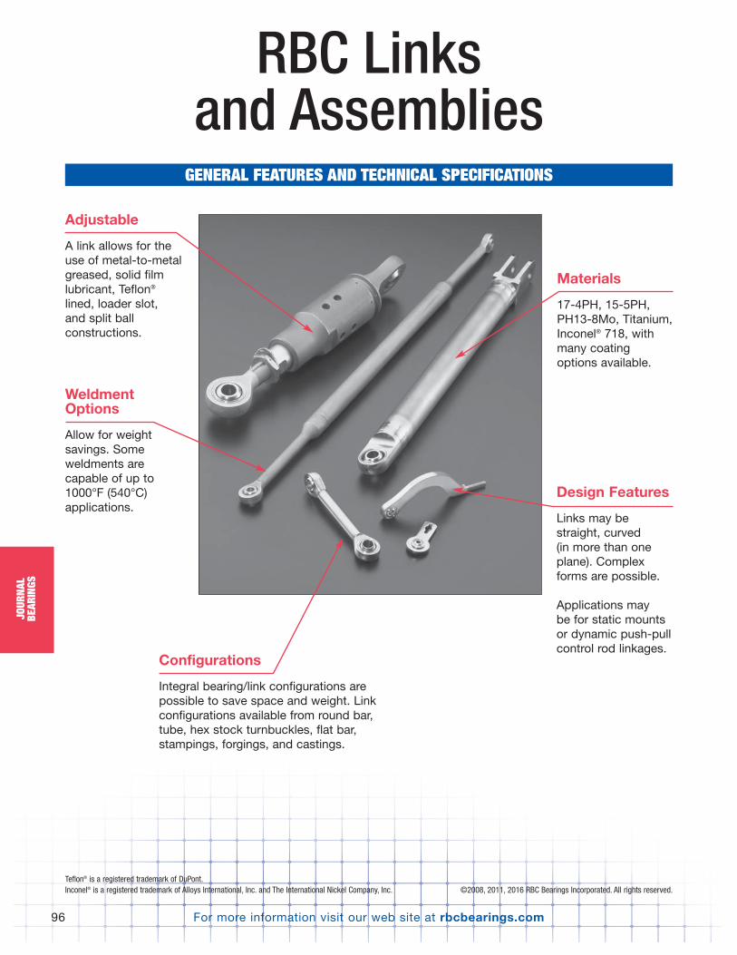
For more information visit our web site at rbcbearings.com96
JOUR
NAL
BEAR
INGS
RBC Links and Assemblies
GENERAL FEATURES AND TECHNICAL SPECIFICATIONS
Materials
17-4PH, 15-5PH, PH13-8Mo, Titanium,Inconel® 718, withmany coatingoptions available.
Weldment Options
Allow for weightsavings. Someweldments are capable of up to1000°F (540°C)applications.
Adjustable
A link allows for the use of metal-to-metalgreased, solid filmlubricant, Teflon®
lined, loader slot, and split ballconstructions.
Teflon® is a registered trademark of DuPont.Inconel® is a registered trademark of Alloys International, Inc. and The International Nickel Company, Inc.
Design Features
Links may bestraight, curved (in more than oneplane). Complexforms are possible.
Applications may be for static mountsor dynamic push-pullcontrol rod linkages.
Configurations
Integral bearing/link configurations arepossible to save space and weight. Linkconfigurations available from round bar,tube, hex stock turnbuckles, flat bar,stampings, forgings, and castings.
©2008, 2011, 2016 RBC Bearings Incorporated. All rights reserved.
PB_073_097_8-30-16_Pln_079_103.qxd 8/30/16 11:09 AM Page 96

For more information visit our web site at rbcbearings.com
NOTES
97For more information visit our web site at rbcbearings.com
PB_073_097_8-30-16_Pln_079_103.qxd 8/30/16 11:09 AM Page 97

For more information visit our web site at rbcbearings.com
AEROSPACE APPLICATIONS
98
AERO
SPAC
EAP
PLIC
ATIO
NS
©2008, 2011, 2016 RBC Bearings Incorporated. All rights reserved.
12
3
4
5
6
7
8
910 11
Helicopter Applications
PB_098_101_8-29-16_Pln_104_107.qxd 8/29/16 8:34 PM Page 98
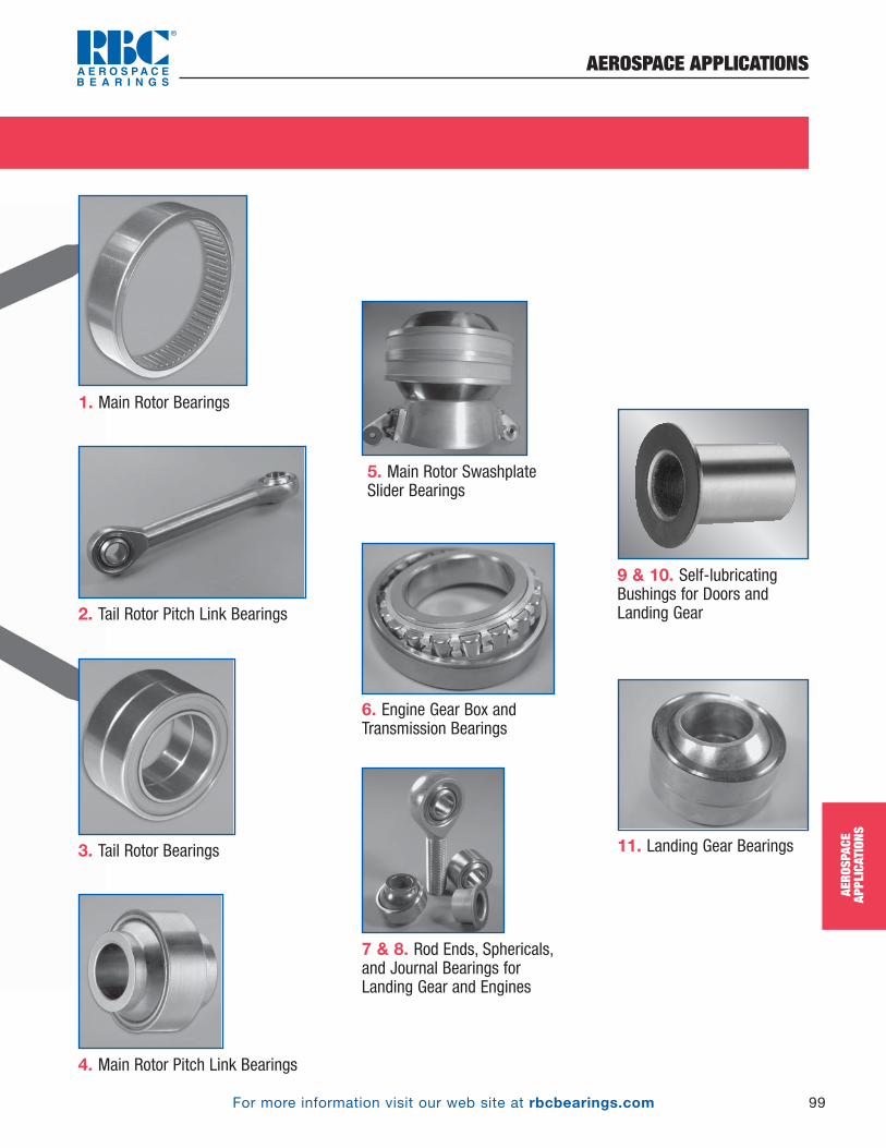
For more information visit our web site at rbcbearings.com
AEROSPACE APPLICATIONS
99
AERO
SPAC
EAP
PLIC
ATIO
NS
2. Tail Rotor Pitch Link Bearings
3. Tail Rotor Bearings
6. Engine Gear Box andTransmission Bearings
1. Main Rotor Bearings
7 & 8. Rod Ends, Sphericals,and Journal Bearings for Landing Gear and Engines
9 & 10. Self-lubricatingBushings for Doors andLanding Gear
4. Main Rotor Pitch Link Bearings
5. Main Rotor SwashplateSlider Bearings
11. Landing Gear Bearings
PB_098_101_8-29-16_Pln_104_107.qxd 8/29/16 8:34 PM Page 99

For more information visit our web site at rbcbearings.com
AEROSPACE APPLICATIONS
100
AERO
SPAC
EAP
PLIC
ATIO
NS
©2008, 2011, 2016 RBC Bearings Incorporated. All rights reserved.
Airframe Applications
1. Radar Gimbal Thin Section Bearings
2. Stowage Bin SupportBearings
3. Airframe Control Bearings
1 2 3 4
56
7
8
9
1011
12
13
PB_098_101_8-29-16_Pln_104_107.qxd 8/29/16 8:34 PM Page 100

For more information visit our web site at rbcbearings.com
AEROSPACE APPLICATIONS
101
AERO
SPAC
EAP
PLIC
ATIO
NS
6. Door Linkage Bearings
5. Door Locking Mechanism and Landing Gear Bushings,Actuator Bearings
7. Engine Bearings
8. Thrust ReverserLinkage Bearings
4. Spherical Plain and BallBearing Rod Ends used inActuator and Aircraft ControlLinkages
11. Landing GearTrunnion Bearings
10. Track Rollers
12. Horizontal StabilizerBearings
13. APU Bearings
9. Ball and Roller Rod Ends used on Control Surfaces
PB_098_101_8-29-16_Pln_104_107.qxd 8/29/16 8:34 PM Page 101

For more information visit our web site at rbcbearings.com
ENGINEERING CONVERSION TABLES
102
ENGI
NEER
ING
CONV
ERSI
ON T
ABLE
S
CONVERSION TABLESTO CONVERT FROM TO MULTIPLY BYAccelerationfoot/second2 ................................meter/second2 .........m/s2 .........................0.3048inch/second2................................meter/second2 .........m/s2 .........................0.0254
Areafoot2...................................................meter2 .................m2...................0.09290304inch2 ..................................................meter2 .................m2...................0.00064516inch2 ...............................................millimeter2 ............mm2 .........................645.16yard2 ..................................................meter2 .................m2.......................0.836127mile2 (U.S. statute) .............................meter2 .................m2........................2589988
Bending Moment or Torquedyne-centimeter...........................newton-meter .........N • m ..................0.0000001kilogram-force-meter...................newton-meter .........N • m.....................9.806650pound-force-inch .........................newton-meter .........N • m ..................0.1129848pound-force-foot..........................newton-meter .........N • m.....................1.355818
EnergyB.T.U. (International Table) ...................joule ....................J ........................1055.056foot-pound-force .................................joule ....................J ........................1.355818kilowatt-hour...................................megajoule ..............MJ.................................3.6
Forcekilogram-force...................................newton..................N........................9.806650kilopond-force ...................................newton..................N........................9.806650pound-force (lbf avoirdupois).............newton..................N........................4.448222
Lengthfathom................................................meter...................m............................1.8288foot .....................................................meter...................m............................0.3048inch .................................................millimeter..............mm ..............................25.4microinch .......................................micrometer .............um...........................0.0254micron (_n)......................................millimeter..............mm ..........................0.0010mile (U.S. statute) ...............................meter...................m........................1609.344yard ....................................................meter...................m............................0.9144nautical mile (UK) ...............................meter...................m..........................1853.18
MassKilogram-force-second2/meter(mass) ...........................................kilogram................kg .......................9.806650
kilogram-mass .................................kilogram................kg .................................1.0pound-mass .....................................kilogram................kg .....................0.4535924ton (long, 2240 lbm).........................kilogram................kg .......................1016.047ton (short, 2000 lbm)........................kilogram................kg .......................907.1847tonne................................................kilogram................kg .......................1000.000
PowerB.T.U. (International Table)/hour ...........watt....................W........................0.293071B.T.U. (International Table)/minute........watt....................W........................17.58426horsepower (550 ft lbf/s) ..................kilowatt ................kW.......................0.745700B.T.U. (thermochemical)/minute...........watt....................W........................17.57250
Pressure or Stress (Force/Area)newton/meter2 ...................................pascal..................Pa ...........................1.0000kilogram-force/centimeter2 ................pascal..................Pa .......................98066.50kilogram-force/meter2........................pascal..................Pa .......................9.806650kilogram-force/millimeter2 .................pascal..................Pa ........................9806650pound-force/foot2...............................pascal..................Pa .......................47.88026pound-force/inch2 (psi) ..................megapascal............MPa................0.006894757
Temperaturedegree Celsius..............................degree Kelvin ............°K.............tk = tc + 273.15degree Fahrenheit ........................degree Kelvin ............°K.......k = 5/9 (tf + 459.67)degree Fahrenheit........................degree Celsius ...........°C ............tc = 5/9 (tf – 32)
Velocityfoot/minute...................................meter/second...........m/s ........................0.00508foot/second ..................................meter/second...........m/s ..........................0.3048inch/second..................................meter/second...........m/s ..........................0.0254kilometer/hour..............................meter/second...........m/s ........................0.27778mile/hour (U.S. statute).................meter/second...........m/s ........................0.44704mile/hour (U.S. statute) ................kilometer/hour .........km/h .....................1.609344
Volumefoot3...................................................meter3 .................m3...................0.02831685gallon (U.S. liquid) ................................liter .....................l.........................3.785412liter ....................................................meter3 .................m3 .............................0.001inch3 ..................................................meter3 .................m3.............0.00001638706inch3 ..............................................centimeter3 ............cm3......................16.38706inch3 ...............................................millimeter3 ............mm3 .....................16387.06ounce (U.S. fluid)............................centimeter3 ............cm3......................29.57353yard3 ..................................................meter3 .................m3.....................0.7645549
VISCOSITY CONVERSION TABLESUS R’ E cSt
Saybolt (sec.) Redwood (sec.) Engler (deg.) Centistokes3540455055606570758085909510011012013014015016017018019020022024026028030032535037540042545047550055060065070075080085090095010001200140016001800200025003000350040004500500055006000650070007500800085009000950010000
32.236.240.644.949.153.557.962.367.671.075.179.684.288.497.1105.9114.8123.6132.4141.1150.0158.8167.5176.4194.0212229247265287309331353375397419441485529573617661705749793837882105812341411158717632204264630873526396744084849529057306171661270537494793483758816
1.181.321.461.601.751.882.022.152.312.422.552.682.812.953.213.493.774.044.324.594.885.155.445.726.286.857.387.958.519.249.9510.711.412.112.813.514.215.617.018.519.921.322.724.225.627.028.434.139.845.55157718599114128142156170185199213227242256270284
274.3597.48.910.411.813.114.515.817.018.219.420.623.025.027.529.832.134.336.538.841.043.247.551.956.560.564.970.375.881.286.892.097.410310811913014115216317318419520621726030234739043354265075886797410821150130014001510163017401850196020702200
PB_102_104_8-29-16_Pln_108_112.qxd 8/29/16 8:34 PM Page 102

For more information visit our web site at rbcbearings.com
ENGINEERING CONVERSION TABLES
103
ENGI
NEER
ING
CONV
ERSI
ON T
ABLE
S
INCHES TO MILLIMETERS - UNITSInches 0 1 2 3 4 5 6 7 8
0 0.0000 0.000 25.400 50.800 76.200 101.600 127.000 152.400 177.800 203.200
228.600
1/16 0.0625 1.588 26.988 52.388 77.788 103.188 128.588 153.988 179.388 204.788
230.188
1/8 0.1250 3.175 28.575 53.975 79.375 104.775 130.175 155.575 180.975 206.375
231.775
3/16 0.1875 4.763 30.162 55.562 80.962 106.362 131.762 157.162 182.562 207.962
233.362
1/4 0.2500 6.350 31.750 57.150 82.550 107.950 133.350 158.750 184.150 209.550
234.950
5/16 0.3125 7.938 33.338 58.738 84.138 109.538 134.938 160.338 185.735 211.138
236.538
3/8 0.3750 9.525 34.925 60.325 85.725 111.125 136.525 161.925 187.325 212.725
238.125
7/16 0.4375 11.112 36.512 61.912 87.312 112.712 138.112 163.512 188.912 214.312
239.712
1/2 0.5000 12.700 38.100 63.500 88.900 114.300 139.700 165.100 190.500 215.900
241.300
9/16 0.5625 14.288 39.688 65.088 90.488 115.888 141.288 166.688 192.088 217.488
242.888
5/8 0.6250 15.875 41.275 66.675 92.075 117.475 142.875 168.275 193.675 219.075
244.475
11/16 0.6875 17.462 42.862 68.262 93.662 119.062 144.462 169.862 195.262 220.662
246.062
3/4 0.7500 19.050 44.450 69.850 95.250 120.650 146.050 171.450 196.850 222.250
247.650
13/16 0.8125 20.638 46.038 71.438 96.838 122.238 147.638 173.038 198.438 223.838
249.238
7/8 0.8750 22.225 47.625 73.025 98.425 123.825 149.225 174.625 200.025 225.425
250.825
15/16 0.9375 23.812 49.212 74.612 100.012 125.412 150.812 176.212 201.612 227.012
252.412
Inches 109 11 12 13 14 15
0 0.0000 254.000 279.400 304.800 330.200 355.600 381.0001/16 0.0625 255.588 280.988 306.388 331.788 357.188 382.5881/8 0.1250 257.175 282.575 307.975 333.375 358.775 384.1753/16 0.1875 258.762 284.162 309.562 334.962 360.362 385.7621/4 0.2500 260.350 285.750 311.150 336.550 361.950 387.350
5/16 0.3125 261.938 287.338 312.738 338.138 363.538 388.9383/8 0.3750 263.525 288.925 314.325 339.725 365.125 390.5257/16 0.4375 265.112 290.512 315.912 341.312 366.712 392.1121/2 0.5000 266.700 292.100 317.500 342.900 368.300 393.7009/16 0.5625 268.288 293.688 319.088 344.488 369.888 395..288
5/8 0.6250 269.875 295.275 320.675 346.075 371.475 396.87511/16 0.6875 271.462 296.862 322.262 347662 373.062 398.4623/4 0.7500 273.050 298.450 323.850 349.250 374.650 400.05013/16 0.8125 274.638 300.038 325.438 350.838 376.238 401.6387/8 0.8750 276.225 301.625 327.025 352.425 377.825 403.22515/16 0.9375 277.812 303.212 328.612 354.012 379.412 404.812
FRACTIONSUNITS1/10" 1/100" 1/1000" 1/10000"Inches 10
Inches mm Inches mm Inches mm Inches mm0 — 2540.1 2.54 0.01 0.254 0.001 0.0254 0.0001 0.002541 25.4 279.40.2 5.08 0.02 0.508 0.002 0.0508 0.0002 0.005082 50.8 304.80.3 7.62 0.03 0.762 0.003 0.0762 0.0003 0.007623 76.2 330.20.4 10.16 0.04 1.016 0.004 0.1016 0.0004 0.010164 101.6 355.60.5 12.70 0.05 1.270 0.005 0.1270 0.0005 0.012705 127 3810.6 15.24 0.06 1.524 0.006 0.1524 0.0006 0.015246 152.4 406.40.7 17.78 0.07 1.778 0.007 0.1778 0.0007 0.017787 177.8 431.80.8 20.32 0.08 2.032 0.008 0.2032 0.0008 0.020328 203.2 457.20.9 22.86 0.09 2.286 0.009 0.2286 0.0009 0.022869 228.6 482.6
MILLIMETERS TO INCHES - UNITSmm 10 20 30 40 50 60 70 80 90
0 — 0.39370 0.78740 1.18110 1.57480 1.96850 2.36220 2.75591 3.14961 3.543311 0.03937 0.43307 0.82677 1.22047 1.61417 2.00787 2.40157 2.79528 3.18898 3.582682 0.07874 0.47244 0.86614 1.25984 1.65354 2.04724 2.44094 2.83465 3.22835 3.622053 0.11811 0.51181 0.90551 1.29921 1.69291 2.08661 2.48031 2.87402 3.26772 3.661424 0.15748 0.55118 0.94488 1.33858 1.73228 2.12598 2.51969 2.91339 3.30709 3.700795 0.19685 0.59055 0.98425 1.37795 1.77165 2.16535 2.55906 2.95276 3.34646 3.740166 0.23622 0.62992 1.02362 1.41732 1.71102 2.20472 2.59843 2.99213 3.38583 3.779537 0.27559 0.66929 1.06299 1.45669 1.85039 2.24409 2.63780 3.03150 3.42520 3.818908 0.31496 0.70866 1.10236 1.49606 1.88976 2.28346 2.67717 3.07087 3.46457 3.858279 0.35433 0.74803 1.14173 1.53543 1.92913 2.32283 2.71654 3.11024 3.50394 3.89764
FRACTIONS1/10 mm 1/100 mm 1/1000 mm
mm 100 200 300
mm inches mm inches mm inches0 — 3.93701 7.87402 11.81100
0.1 0.00394 0.01 0.00039 0.001 0.000039
10 0.39370 4.33071 8.26772 12.20470
0.2 0.00787 0.02 0.00079 0.002 0.000079
20 0.78740 4.72441 8.66142 12.59840
0.3 0.01181 0.03 0.00118 0.003 0.000118
30 1.18110 5.11811 9.05512 12.99210
0.4 0.01575 0.04 0.00157 0.004 0.000157
40 1.57480 5.51181 9.44882 13.38580
0.5 0.01969 0.05 0.00197 0.005 0.000197
50 1.96850 5.90551 9.84252 13.77950
0.6 0.02362 0.06 0.00236 0.006 0.000236
60 2.36220 6.29921 10.23620 14.17320
0.7 0.02756 0.07 0.00276 0.007 0.000276
70 2.75591 6.69291 10.62990 14.56690
0.8 0.03150 0.08 0.00315 0.008 0.000315
80 3.14961 7.08661 11.02360 14.96060
0.9 0.03543 0.09 0.00354 0.009 0.000354
90 3.54331 7.48031 11.41730 15.35430
B.S.I. Norm No. 350 A.S.A. Norm No. B48.1} 1 inch = 25.400 mm
(exact)
DIN 4890, 1mm = 1 inches25.4
PB_102_104_8-29-16_Pln_108_112.qxd 8/29/16 8:34 PM Page 103
For more information visit our web site at rbcbearings.com
NOTES
104
PB_102_104_8-29-16_Pln_108_112.qxd 8/29/16 8:34 PM Page 104

unique design solutionsto complex problems
The Global Leader in Aerospace Bearings
Spherical Bearings
Rod End Bearings
Journal Bearings
Links and Assemblies
www.rbcbearings.com
Plain Bearings
Plain Bearings
RBC A
EROSPA
CE BEA
RING
SPLA
IN BEA
RING
Sw
ww
.rbcbearings.com
RBC Aerospace Bearing Products
Spherical Bearings• MS approved to AS81820
(formerly MIL-B-81820) • Boeing and Airbus approved • Self-lubricating • Metal-to-Metal • Loader slots • High temperature • Low coefficient of friction • Special configurations and materials
Rod End Bearings• MS approved to AS81935
(formerly MIL-B-81935)• Boeing and Airbus approved • Self-lubricating • Metal-to-Metal • Loader slots • High temperature • Low coefficient of friction • Special configurations and materials
Track Rollers• MS approved to AS39901
(formerly MIL-B-3990)• Boeing and Airbus approved • ATF single row and ATL double row • Sealed with lube holes and grooves • Heavy duty cross-sections• Advanced AeroCres® materials available
Cargo Roller Bearings• Boeing approved • Features precision ground, semi-ground,
and unground ball bearings• Offered in caged and full complement
configurations
Ball Bearing Rod Ends• MS approved to AS6039
(formerly MIL-B-6039) • Boeing approved • Various shank configurations • Low coefficient of friction• Advanced AeroCres® materials available
Cam Followers• MS approved to AS39901
(formerly MIL-B-3990)• Advanced AeroCres® materials available• Maximum corrosion resistance• Superior lubricants and seals to reduce
maintenance
Journal Bearings• MS approved to AS81934
(formerly MIL-B-81934)• Boeing and Airbus approved • Plain and flanged • Self-lubricating • High temperature • High loads • Available in inch and metric sizes
Thin Section Ball Bearings• Standard cross-sections to one inch • Stainless steel and other materials are
available • Sizes to 40 inches • Seals available on all sizes and
standard cross-sections• Super duplex configurations
Load Slot Bearings• Spherical and rod end designs• Superior ball-to-race conformity• Reduced maintenance cost• Variety of race materials available• Boeing approved
Double Row Hourglass Bearings• Boeing approved• High Radial and Axial Load Ratings• Low Torque• Integral Swage Grooves Available• Pyrowear®, Cronidur30®, 52100, 9310 or 440C
Specials• Many specialty bearings, custom-
designed and configured for diverse aerospace applications
• Capability for advanced aerospace specialty corrosion resistant and high temperature materials
Airframe Control Ball Bearings• MS approved to AS7949
(formerly MIL-B-7949)• Boeing and Airbus approved • Single and double row • Radial, self-aligning, and pulley series • 52100 Cad plated and 440C stainless
RBC Bearings Incorporated has been producing bearings in the USA since 1919.RBC offers a full line of aerospace bearings, including unique custom configurations.
www.rbcbearings.com
© 2008, 2011, 2016 RBC Bearings Incorporated. All rights reserved.
This document contains a general overview of the products and features described herein. It is solely for informational purposes, does not represent a warranty of theinformation contained herein, and is not to be construed as an offer to sell or a solicitation to buy. Contact RBC Bearings for detailed information suitable to your specificapplications. RBC Bearings reserves the right to modify its products and related product information at any time without prior notice.
Some of the products listed herein may be covered by one or more issued and pending U.S. or foreign patents. Contact RBC Bearings for product specific information.
Innovation. Commitment. Quality.
RBC-ACRE REV. 10/16
PB_FBcvrs_8-29-16_Layout 1 8/29/16 8:35 PM Page 1