RB202 Redback Tyre Changer Manual
19
200. 2018 TYRE CHANGER INSTRUCTION & MAINTENANCE MANUAL We follow the way that wheel moving! Read this entire manual carefully and completely before installation or operation of the tire changer
Transcript of RB202 Redback Tyre Changer Manual

200. 2018
TYRE CHANGER
INSTRUCTION & MAINTENANCE MANUAL
We follow the way that wheel moving!
Read this entire manual carefully and completely before installation or operation of the tire changer
200. 2018
- 1 –
INDEX PAGE 1. Introduction: .................................................................................................................................................................. 2 2. Warning label and sticking position: ............................................................................................................................. 2 3. Technical data ............................................................................................................................................................... 3 4. Transport: ...................................................................................................................................................................... 3 5. Unpacking & Inspection: .............................................................................................................................................. 3 6. Workplace requirements: .............................................................................................................................................. 3 7. Position and installation: ............................................................................................................................................... 4 8. Electricity and Pneumatic connections: ........................................................................................................................ 4 9. Adjusting operation: ...................................................................................................................................................... 4 9.1. Breaking the tyre bead: ........................................................................................................................................... 5 9.2. Demounting the tyre : ................................................................................................................................................ 5 9.3. Mounting the tyre :..................................................................................................................................................... 6 10. Inflating the tire: ......................................................................................................................................................... 6 11. Moving machine: ........................................................................................................................................................ 7 12. Maintenance: ............................................................................................................................................................... 7 13. Trouble shooting table: ............................................................................................................................................... 8 14. Guide for ordering spare parts .................................................................................................................................... 8 15. Wearing spare parts list ............................................................................................................................................. 10 16. Exploded drawing: .................................................................................................................................................... 10 15. Circuit diagram: ........................................................................................................................................................ 18 16. Pneumatic drawing: .................................................................................................................................................. 18
200. 2018
- 2 -
Tyre Changer Warning This instruction manual is important for the machine, please read carefully before installation and use; also it is important for safe use and machine maintenance of machine. Please keep this manual properly in order to further maintenance of the machine.
1. Introduction: Application Range: The semi-automatic tyre changer is especially designed for demounting / mounting tyres from wheel rims. Caution:Please use the machine only for purpose for which it is designed, don't use it for other purposes. Manufacturer shall not be liable for any damage or injury caused by failure to comply with these regulations. Safety regulation: Use of this machine is especially reserved to trained and qualified professional persons, those who already read the introduction manual carefully, or someone have the experience for operating similar machinery. Any changes and beyond the scope of use on this machine without manufacturer’s permission or do not according to the manual, may cause the malfunction and damage to machine, manufacturer can cancel warranty coverage for above. If some parts are damaged due to some reason, please replace them according to the spare parts list. (Attention: warranty is one year after manufactures’ delivery date; warranty excludes the easy-broken parts).
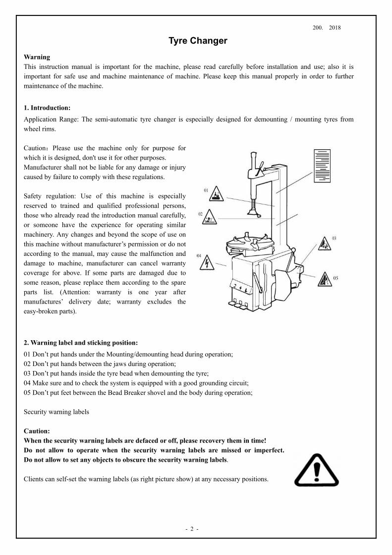
2. Warning label and sticking position:
01 Don’t put hands under the Mounting/demounting head during operation; 02 Don’t put hands between the jaws during operation; 03 Don’t put hands inside the tyre bead when demounting the tyre; 04 Make sure and to check the system is equipped with a good grounding circuit; 05 Don’t put feet between the Bead Breaker shovel and the body during operation; Security warning labels Caution: When the security warning labels are defaced or off, please recovery them in time! Do not allow to operate when the security warning labels are missed or imperfect. Do not allow to set any objects to obscure the security warning labels. Clients can self-set the warning labels (as right picture show) at any necessary positions.
200. 2018
- 3 –
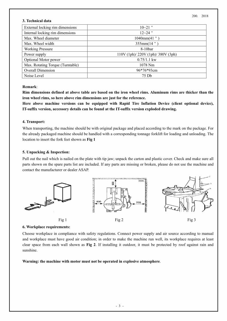
3. Technical data External locking rim dimensions 10~21" Internal locking rim dimensions 12~24" Max. Wheel diameter 1040mm(41") Max. Wheel width 355mm(14") Working Pressure 8-10bar Power supply 110V (1ph)/ 220V (1ph)/ 380V (3ph) Optional Motor power 0.75/1.1 kw Max. Rotating Torque (Turntable) 1078 Nm Overall Dimension 96*76*93cm Noise Level 75 Db
Remark: Rim dimensions defined at above table are based on the iron wheel rims. Aluminum rims are thicker than the iron wheel rims, so here above rim dimensions are just for the reference. Here above machine versions can be equipped with Rapid Tire Inflation Device (client optional device), IT-suffix version, accessory details can be found at the IT-suffix version exploded drawing.
4. Transport: When transporting, the machine should be with original package and placed according to the mark on the package. For the already packaged machine should be handled with a corresponding tonnage forklift for loading and unloading. The location to insert the fork feet shown as Fig 1
5. Unpacking & Inspection:
Pull out the nail which is nailed on the plate with tip jaw; unpack the carton and plastic cover. Check and make sure all parts shown on the spare parts list are included. If any parts are missing or broken, please do not use the machine and contact the manufacturer or dealer ASAP.
Fig 1 Fig 2 Fig 3
6. Workplace requirements: Choose workplace in compliance with safety regulations. Connect power supply and air source according to manual and workplace must have good air condition; in order to make the machine run well, its workplace requires at least clear space from each wall shown as Fig 2. If installing it outdoor, it must be protected by roof against rain and sunshine. Warning: the machine with motor must not be operated in explosive atmosphere.
200. 2018
- 4 -
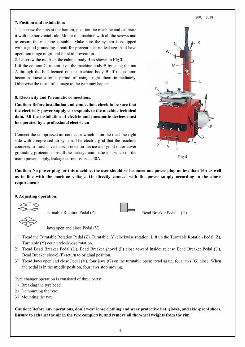
7. Position and installation: 1. Unscrew the nuts at the bottom, position the machine and calibrate it with the horizontal rule. Mount the machine with all the screws and to ensure the machine is stable. Make sure the system is equipped with a good grounding circuit for prevent electric leakage. And have operation range of ground for skid prevention. 2. Unscrew the nut A on the cabinet body B as shown in Fig 3. Lift the column C; mount it on the machine body B by using the nut A through the bolt located on the machine body B. If the column becomes loose after a period of using, tight them immediately. Otherwise the result of damage to the tyre may happen.
8. Electricity and Pneumatic connections:
Caution: Before installation and connection, check to be sure that the electricity power supply corresponds to the machine technical data. All the installation of electric and pneumatic devices must be operated by a professional electrician. Connect the compressed air connector which is on the machine right side with compressed air system. The electric grid that the machine connects to must have fuses protection device and good outer cover grounding protection. Install the leakage automatic air switch on the maim power supply, leakage current is set at 30A Caution: No power plug for this machine, the user should self-connect one power plug no less than 16A as well as in line with the machine voltage. Or directly connect with the power supply according to the above requirements.
9. Adjusting operation:
Turntable Rotation Pedal (Z) Bead Breaker Pedal (U)
Jaws open and close Pedal (V)
1) Tread the Turntable Rotation Pedal (Z), Turntable (Y) clockwise rotation; Lift up the Turntable Rotation Pedal (Z), Turntable (Y) counterclockwise rotation.
2) Tread Bead Breaker Pedal (U), Bead Breaker shovel (F) close toward inside; release Bead Breaker Pedal (U), Bead Breaker shovel (F) return to original position.
3) Tread Jaws open and close Pedal (V), four jaws (G) on the turntable open; tread again, four jaws (G) close. When the pedal is in the middle position, four jaws stop moving.
Tyre changer operation is consisted of three parts: 1)Breaking the tyre bead 2)Demounting the tyre 3)Mounting the tyre Caution: Before any operations, don’t wear loose clothing and wear protective hat, gloves, and skid-proof shoes. Ensure to exhaust the air in the tyre completely, and remove all the wheel weights from the rim.
Fig 4
UVZ T
S
F
CI
M
N
W
K
YG
200. 2018
- 5 –
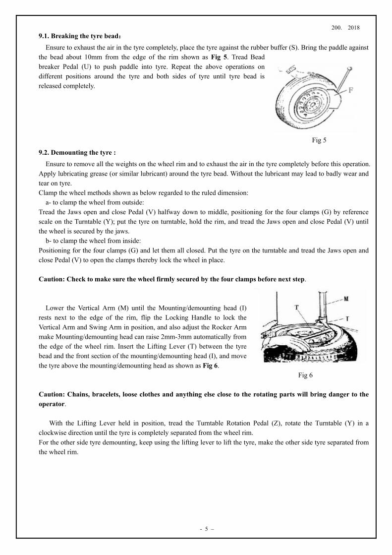
9.1. Breaking the tyre bead: Ensure to exhaust the air in the tyre completely, place the tyre against the rubber buffer (S). Bring the paddle against
the bead about 10mm from the edge of the rim shown as Fig 5. Tread Bead breaker Pedal (U) to push paddle into tyre. Repeat the above operations on different positions around the tyre and both sides of tyre until tyre bead is released completely.
Fig 5
9.2. Demounting the tyre : Ensure to remove all the weights on the wheel rim and to exhaust the air in the tyre completely before this operation.
Apply lubricating grease (or similar lubricant) around the tyre bead. Without the lubricant may lead to badly wear and tear on tyre. Clamp the wheel methods shown as below regarded to the ruled dimension:
a- to clamp the wheel from outside: Tread the Jaws open and close Pedal (V) halfway down to middle, positioning for the four clamps (G) by reference scale on the Turntable (Y); put the tyre on turntable, hold the rim, and tread the Jaws open and close Pedal (V) until the wheel is secured by the jaws.
b- to clamp the wheel from inside: Positioning for the four clamps (G) and let them all closed. Put the tyre on the turntable and tread the Jaws open and close Pedal (V) to open the clamps thereby lock the wheel in place. Caution: Check to make sure the wheel firmly secured by the four clamps before next step.
Lower the Vertical Arm (M) until the Mounting/demounting head (I) rests next to the edge of the rim, flip the Locking Handle to lock the Vertical Arm and Swing Arm in position, and also adjust the Rocker Arm make Mounting/demounting head can raise 2mm-3mm automatically from the edge of the wheel rim. Insert the Lifting Lever (T) between the tyre bead and the front section of the mounting/demounting head (I), and move the tyre above the mounting/demounting head as shown as Fig 6. Fig 6 Caution: Chains, bracelets, loose clothes and anything else close to the rotating parts will bring danger to the operator.
With the Lifting Lever held in position, tread the Turntable Rotation Pedal (Z), rotate the Turntable (Y) in a clockwise direction until the tyre is completely separated from the wheel rim. For the other side tyre demounting, keep using the lifting lever to lift the tyre, make the other side tyre separated from the wheel rim.
200. 2018
- 6 -
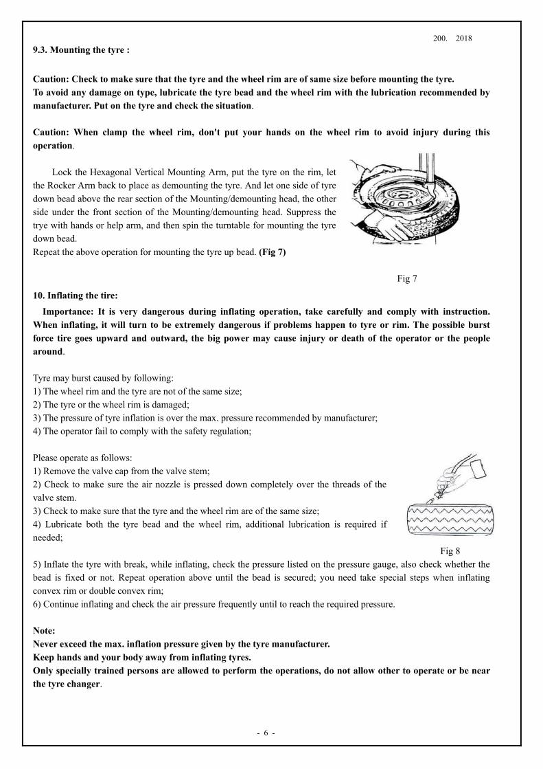
9.3. Mounting the tyre : Caution: Check to make sure that the tyre and the wheel rim are of same size before mounting the tyre. To avoid any damage on type, lubricate the tyre bead and the wheel rim with the lubrication recommended by manufacturer. Put on the tyre and check the situation. Caution: When clamp the wheel rim, don't put your hands on the wheel rim to avoid injury during this operation.
Lock the Hexagonal Vertical Mounting Arm, put the tyre on the rim, let the Rocker Arm back to place as demounting the tyre. And let one side of tyre down bead above the rear section of the Mounting/demounting head, the other side under the front section of the Mounting/demounting head. Suppress the trye with hands or help arm, and then spin the turntable for mounting the tyre down bead. Repeat the above operation for mounting the tyre up bead. (Fig 7)
Fig 7
10. Inflating the tire:
Importance: It is very dangerous during inflating operation, take carefully and comply with instruction. When inflating, it will turn to be extremely dangerous if problems happen to tyre or rim. The possible burst force tire goes upward and outward, the big power may cause injury or death of the operator or the people around. Tyre may burst caused by following: 1) The wheel rim and the tyre are not of the same size; 2) The tyre or the wheel rim is damaged; 3) The pressure of tyre inflation is over the max. pressure recommended by manufacturer; 4) The operator fail to comply with the safety regulation; Please operate as follows: 1) Remove the valve cap from the valve stem; 2) Check to make sure the air nozzle is pressed down completely over the threads of the valve stem. 3) Check to make sure that the tyre and the wheel rim are of the same size; 4) Lubricate both the tyre bead and the wheel rim, additional lubrication is required if needed; Fig 8 5) Inflate the tyre with break, while inflating, check the pressure listed on the pressure gauge, also check whether the bead is fixed or not. Repeat operation above until the bead is secured; you need take special steps when inflating convex rim or double convex rim; 6) Continue inflating and check the air pressure frequently until to reach the required pressure. Note: Never exceed the max. inflation pressure given by the tyre manufacturer. Keep hands and your body away from inflating tyres. Only specially trained persons are allowed to perform the operations, do not allow other to operate or be near the tyre changer.
200. 2018
- 7 –
11. Moving machine: Please use forklift to move the machine. Disconnect the tyre changer from the electricity power supply and
pneumatic power supply, lift the base board and insert the feet of forklift. Then mount the tyre changer machine to a new position and fix it tightly. Note: the place chosen for fixing the tyre changer must meet the safety regulation.
12. Maintenance:
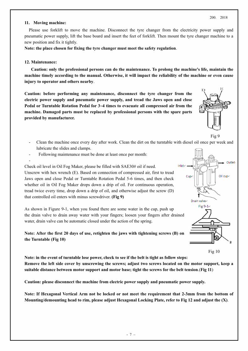
Caution: only the professional persons can do the maintenance. To prolong the machine's life, maintain the machine timely according to the manual. Otherwise, it will impact the reliability of the machine or even cause injury to operator and others nearby. Caution: before performing any maintenance, disconnect the tyre changer from the electric power supply and pneumatic power supply, and tread the Jaws open and close Pedal or Turntable Rotation Pedal for 3~4 times to evacuate all compressed air from the machine. Damaged parts must be replaced by professional persons with the spare parts provided by manufacturer. Fig 9
- Clean the machine once every day after work. Clean the dirt on the turntable with diesel oil once per week and lubricate the slides and clamps.
- Following maintenance must be done at least once per month: -
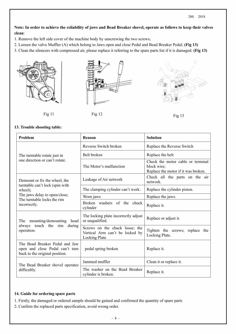
Check oil level in Oil Fog Maker, please be filled with SAE30# oil if need. Unscrew with hex wrench (E). Based on connection of compressed air, first to tread Jaws open and close Pedal or Turntable Rotation Pedal 5-6 times, and then check whether oil in Oil Fog Maker drops down a drip of oil. For continuous operation, tread twice every time, drop down a drip of oil, and otherwise adjust the screw (D) that controlled oil enters with minus screwdriver. (Fig 9) As shown in Figure 9-1, when you found there are some water in the cup, push up the drain valve to drain away water with your fingers; loosen your fingers after drained water, drain valve can be automatic closed under the action of the spring. Note: After the first 20 days of use, retighten the jaws with tightening screws (B) on the Turntable (Fig 10) Fig 10 Note: in the event of turntable lose power, check to see if the belt is tight as follow steps: Remove the left side cover by unscrewing the screws; adjust two screws located on the motor support, keep a suitable distance between motor support and motor base; tight the screws for the belt tension.(Fig 11) Caution: please disconnect the machine from electric power supply and pneumatic power supply. Note: If Hexagonal Vertical Arm not be locked or not meet the requirement that 2-3mm from the bottom of Mounting/demounting head to rim, please adjust Hexagonal Locking Plate, refer to Fig 12 and adjust the (X).
200. 2018
- 8 -
Note: In order to achieve the reliability of jaws and Bead Breaker shovel, operate as follows to keep their valves clean: 1. Remove the left side cover of the machine body by unscrewing the two screws; 2. Loosen the valve Muffler (A) which belong to Jaws open and close Pedal and Bead Breaker Pedal; (Fig 13) 3. Clean the silencers with compressed air, please replace it referring to the spare parts list if it is damaged. (Fig 13)
Fig 11 Fig 12
13. Trouble shooting table:
14. Guide for ordering spare parts
1. Firstly, the damaged or ordered sample should be gained and confirmed the quantity of spare parts 2. Confirm the replaced parts specification, avoid wrong order.
Problem Reason Solution
The turntable rotate just in one direction or can’t rotate.
Reverse Switch broken Replace the Reverse Switch
Belt broken Replace the belt
The Motor’s malfunction Check the motor cable or terminal block wire; Replace the motor if it was broken.
Demount or fix the wheel, the turntable can’t lock (spin with wheel); The jaws delay to open/close; The turntable locks the rim incorrectly.
Leakage of Air network Check all the parts on the air network.
The clamping cylinder can’t work. Replace the cylinder piston.
Worn jaws Replace the jaws. Broken washers of the chuck cylinder Replace it.
The mounting/demounting head always touch the rim during operation.
The locking plate incorrectly adjust or unqualified. Replace or adjust it.
Screws on the chuck loose; the Vertical Arm can’t be locked by Locking Plate
Tighten the screws; replace the Locking Plate.
The Bead Breaker Pedal and Jaw open and close Pedal can’t turn back to the original position.
pedal spring broken Replace it.
The Bead Breaker shovel operates difficultly.
Jammed muffler Clean it or replace it.
The washer on the Bead Breaker cylinder is broken. Replace it.
Fig 13
200. 2018
- 9 –
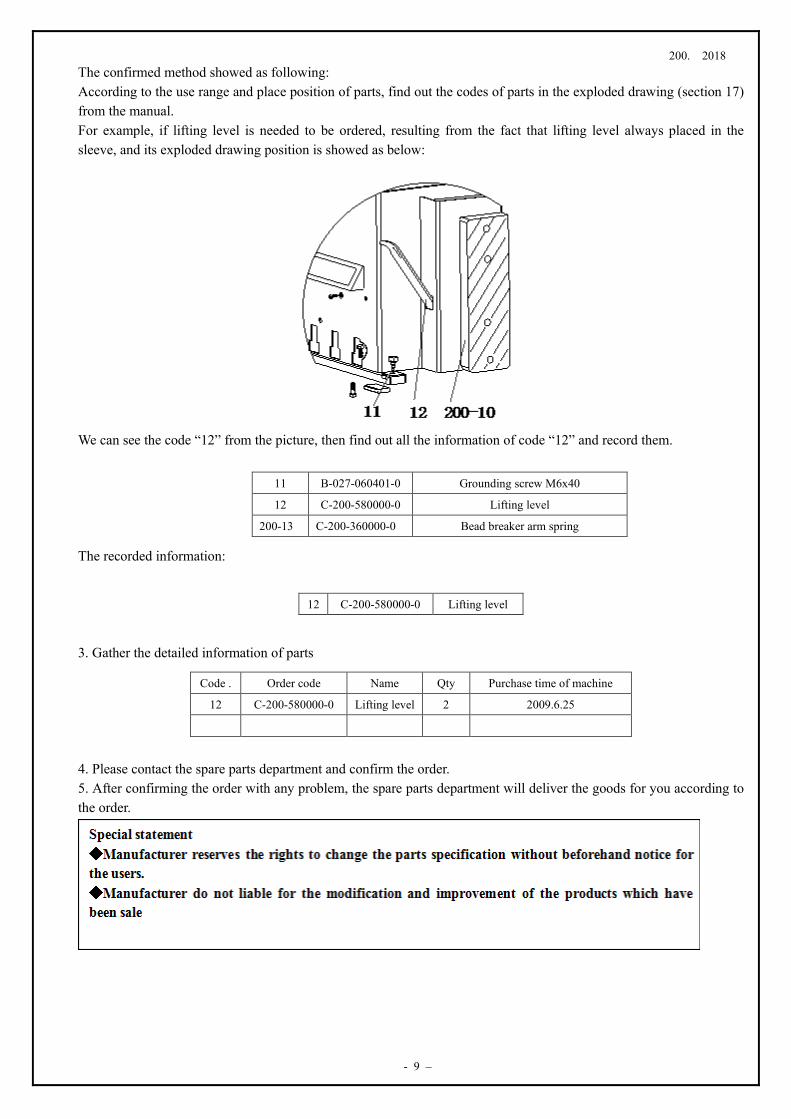
The confirmed method showed as following: According to the use range and place position of parts, find out the codes of parts in the exploded drawing (section 17) from the manual. For example, if lifting level is needed to be ordered, resulting from the fact that lifting level always placed in the sleeve, and its exploded drawing position is showed as below: We can see the code “12” from the picture, then find out all the information of code “12” and record them. The recorded information: 3. Gather the detailed information of parts 4. Please contact the spare parts department and confirm the order. 5. After confirming the order with any problem, the spare parts department will deliver the goods for you according to the order.
11 B-027-060401-0 Grounding screw M6x40
12 C-200-580000-0 Lifting level
200-13 C-200-360000-0 Bead breaker arm spring
12 C-200-580000-0 Lifting level
Code . Order code Name Qty Purchase time of machine
12 C-200-580000-0 Lifting level 2 2009.6.25
200. 2018
- 10 -
15. Wearing spare parts list
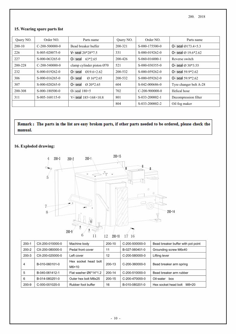
16. Exploded drawing:
Query NO. Order NO. Parts name Query NO. Order NO. Parts name
200-10 C-200-500000-0 Bead breaker buffer 200-321 S-000-175500-0 O- seal Ø173.4×5.3
226 S-005-020075-0 V- seal 20*28*7.5 331 S-000-019262-0 O- seal Ø 19.6*2.62
227 S-000-063265-0 O- seal 63*2.65 200-426 S-060-016000-1 Reverse switch
200-228 C-200-540000-0 clamp cylinder piston Ø70 521 S-000-030355-0 O- seal Ø 30*3.55
232 S-000-019262-0 O- seal Ø19.6×2.62 200-532 S-000-059262-0 O- seal 59.9*2.62
306 S-000-016265-0 O- seal Ø 16*2.65 200-532 S-000-059262-0 O- seal 59.9*2.62
307 S-000-020265-0 O- seal Ø 20*2.65 604 S-042-000686-0 Tyre changer belt A-28
200-308 S-000-180500-0 O- seal 180×5 702 C-200-900000-0 Helical hose
311 S-005-168115-0 V- seal 185×168×10.8 801 S-033-200002-1 Decompression filter
804 S-033-200002-2 Oil fog maker
200-1 CX-200-010000-0 Machine body 200-10 C-200-500000-0 Bead breaker buffer with pot point
200-2 CX-200-080000-0 Pedal front cover 11 B-027-060401-0 Grounding screw M6x40
200-3 CX-200-020000-0 Left cover 12 C-200-580000-0 Lifting lever
4 B-010-060101-0 Hex socket head bolt M6×10
200-13 C-200-360000-0 Bead breaker arm spring
5 B-040-061412-1 Flat washer Ø6*14*1.2 200-14 C-200-510000-0 Bead breaker arm rubber
6 B-014-080251-0 Outer hex bolt M8x25 200-15 C-200-470000-0 Oil-water box
200-9 C-000-001020-0 Rubber foot buffer 16 B-010-080201-0 Hex socket head bolt M8×20
200. 2018
- 11 –
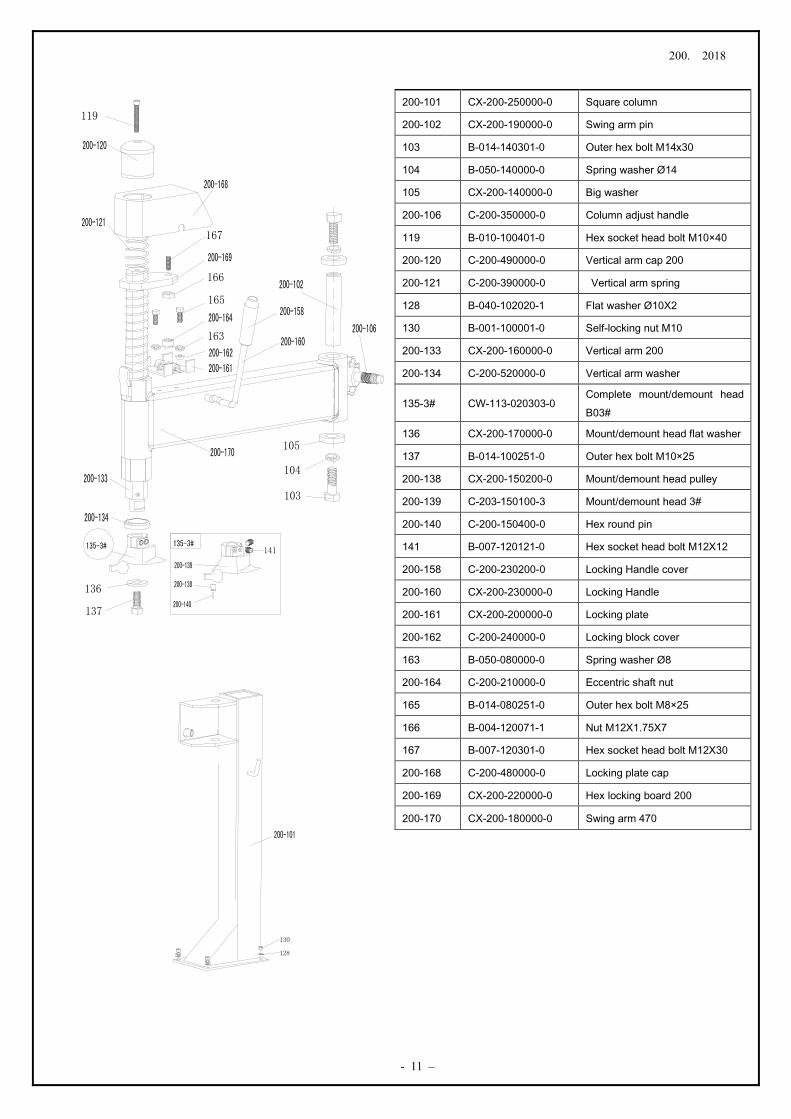
200-101 CX-200-250000-0 Square column
200-102 CX-200-190000-0 Swing arm pin
103 B-014-140301-0 Outer hex bolt M14x30
104 B-050-140000-0 Spring washer Ø14
105 CX-200-140000-0 Big washer
200-106 C-200-350000-0 Column adjust handle
119 B-010-100401-0 Hex socket head bolt M10×40
200-120 C-200-490000-0 Vertical arm cap 200
200-121 C-200-390000-0 Vertical arm spring
128 B-040-102020-1 Flat washer Ø10X2
130 B-001-100001-0 Self-locking nut M10
200-133 CX-200-160000-0 Vertical arm 200
200-134 C-200-520000-0 Vertical arm washer
135-3# CW-113-020303-0 Complete mount/demount head B03#
136 CX-200-170000-0 Mount/demount head flat washer
137 B-014-100251-0 Outer hex bolt M10×25
200-138 CX-200-150200-0 Mount/demount head pulley
200-139 C-203-150100-3 Mount/demount head 3#
200-140 C-200-150400-0 Hex round pin
141 B-007-120121-0 Hex socket head bolt M12X12
200-158 C-200-230200-0 Locking Handle cover
200-160 CX-200-230000-0 Locking Handle
200-161 CX-200-200000-0 Locking plate
200-162 C-200-240000-0 Locking block cover
163 B-050-080000-0 Spring washer Ø8
200-164 C-200-210000-0 Eccentric shaft nut
165 B-014-080251-0 Outer hex bolt M8×25
166 B-004-120071-1 Nut M12X1.75X7
167 B-007-120301-0 Hex socket head bolt M12X30
200-168 C-200-480000-0 Locking plate cap
200-169 CX-200-220000-0 Hex locking board 200
200-170 CX-200-180000-0 Swing arm 470
36
119
167
163
165
166
137
136
105
104
103
200. 2018
- 12 -
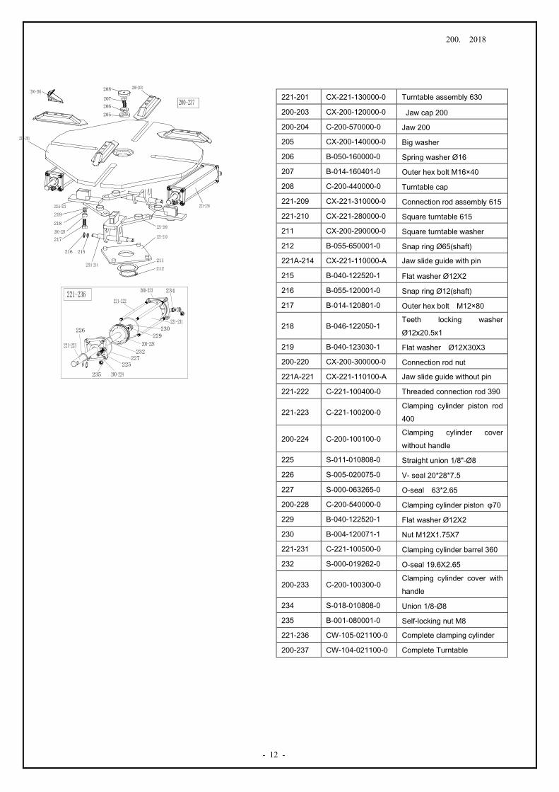
221-201 CX-221-130000-0 Turntable assembly 630
200-203 CX-200-120000-0 Jaw cap 200
200-204 C-200-570000-0 Jaw 200
205 CX-200-140000-0 Big washer
206 B-050-160000-0 Spring washer Ø16
207 B-014-160401-0 Outer hex bolt M16×40
208 C-200-440000-0 Turntable cap
221-209 CX-221-310000-0 Connection rod assembly 615
221-210 CX-221-280000-0 Square turntable 615
211 CX-200-290000-0 Square turntable washer
212 B-055-650001-0 Snap ring Ø65(shaft)
221A-214 CX-221-110000-A Jaw slide guide with pin
215 B-040-122520-1 Flat washer Ø12X2
216 B-055-120001-0 Snap ring Ø12(shaft)
217 B-014-120801-0 Outer hex bolt M12×80
218 B-046-122050-1 Teeth locking washer Ø12x20.5x1
219 B-040-123030-1 Flat washer Ø12X30X3
200-220 CX-200-300000-0 Connection rod nut
221A-221 CX-221-110100-A Jaw slide guide without pin
221-222 C-221-100400-0 Threaded connection rod 390
221-223 C-221-100200-0 Clamping cylinder piston rod 400
200-224 C-200-100100-0 Clamping cylinder cover without handle
225 S-011-010808-0 Straight union 1/8"-Ø8
226 S-005-020075-0 V- seal 20*28*7.5
227 S-000-063265-0 O-seal 63*2.65
200-228 C-200-540000-0 Clamping cylinder piston φ70
229 B-040-122520-1 Flat washer Ø12X2
230 B-004-120071-1 Nut M12X1.75X7
221-231 C-221-100500-0 Clamping cylinder barrel 360
232 S-000-019262-0 O-seal 19.6X2.65
200-233 C-200-100300-0 Clamping cylinder cover with handle
234 S-018-010808-0 Union 1/8-Ø8
235 B-001-080001-0 Self-locking nut M8
221-236 CW-105-021100-0 Complete clamping cylinder
200-237 CW-104-021100-0 Complete Turntable
216
217
219
215
211
212
218
206
207
205
208
232
226
225
234
235
230229
227
200. 2018
- 13 –
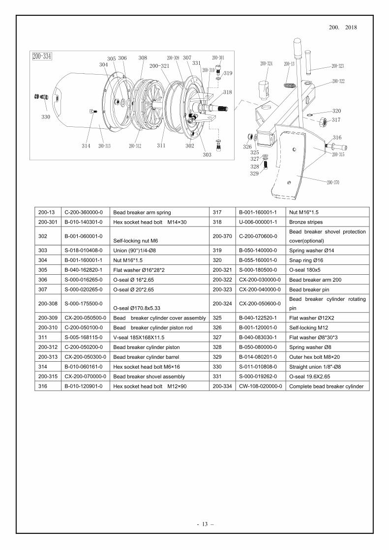
200-13 C-200-360000-0 Bead breaker arm spring 317 B-001-160001-1 Nut M16*1.5
200-301 B-010-140301-0 Hex socket head bolt M14×30 318 U-006-000001-1 Bronze stripes
302 B-001-060001-0 Self-locking nut M6
200-370 C-200-070600-0 Bead breaker shovel protection cover(optional)
303 S-018-010408-0 Union (90°)1/4-Ø8 319 B-050-140000-0 Spring washer Ø14
304 B-001-160001-1 Nut M16*1.5 320 B-055-160001-0 Snap ring Ø16
305 B-040-162820-1 Flat washer Ø16*28*2 200-321 S-000-180500-0 O-seal 180x5
306 S-000-016265-0 O-seal Ø 16*2.65 200-322 CX-200-030000-0 Bead breaker arm 200
307 S-000-020265-0 O-seal Ø 20*2.65 200-323 CX-200-040000-0 Bead breaker pin
200-308 S-000-175500-0 O-seal Ø170.8x5.33
200-324 CX-200-050600-0 Bead breaker cylinder rotating pin
200-309 CX-200-050500-0 Bead breaker cylinder cover assembly 325 B-040-122520-1 Flat washer Ø12X2
200-310 C-200-050100-0 Bead breaker cylinder piston rod 326 B-001-120001-0 Self-locking M12
311 S-005-168115-0 V-seal 185X168X11.5 327 B-040-083030-1 Flat washer Ø8*30*3
200-312 C-200-050200-0 Bead breaker cylinder piston 328 B-050-080000-0 Spring washer Ø8
200-313 CX-200-050300-0 Bead breaker cylinder barrel 329 B-014-080201-0 Outer hex bolt M8×20
314 B-010-060161-0 Hex socket head bolt M6×16 330 S-011-010808-0 Straight union 1/8"-Ø8
200-315 CX-200-070000-0 Bead breaker shovel assembly 331 S-000-019262-0 O-seal 19.6X2.65
316 B-010-120901-0 Hex socket head bolt M12×90 200-334 CW-108-020000-0 Complete bead breaker cylinder
316
317
320
331
325326
327
328329
311
303
306304
305 308 307
330
302314
318
319
200-321
200. 2018
- 14 -
200-480
423
442
445
420
438
439411
440
410437
427
441
417
418
409
405
406
408407
432
434
425430
433
429
616459
423422
428
452
457
453
422
200. 2018
- 15 –
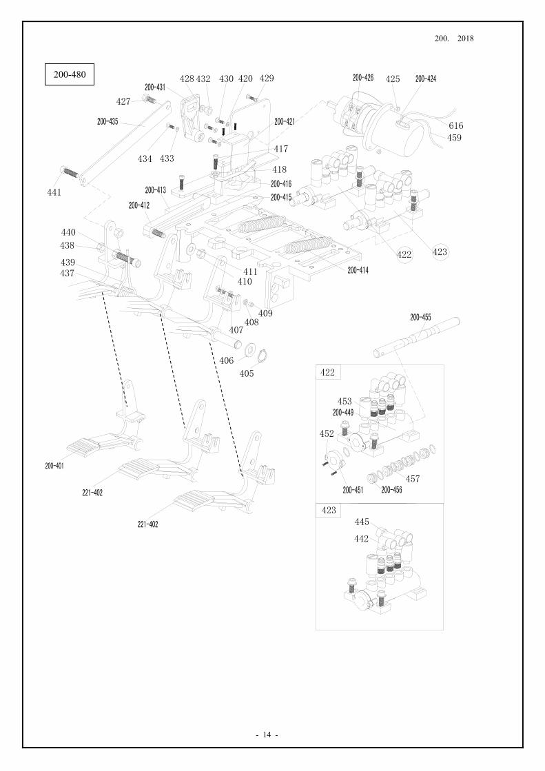
200-401 C-200-060400-0 Reverse switch pedal 428 B-040-061210-1 Flat washer Ø6*12*1
221-402 C-221-060300-0 5-way valve pedal(right) 429 B-040-040000-1 Flat washer Ø 4
405 B-055-120001-0 Snap ring Ø12(shaft)
430 B-024-040161-0 Cross-round head screw M4*16
406 B-040-122520-1 Flat washer Ø12X2 200-431 C-200-530000-0 Reverse switch handle
407 B-017-040301-0 Cross head screw M4X30 432 B-001-060001-0 Self-locking nut M6
408 B-040-040000-1 Flat washer Ø 4 433 B-040-030000-1 Flat washer Ø3
409 B-001-040001-0 Self-locking nut M4 434 B-024-030161-0 Cross head screwM3×16
410 B-001-080001-0 Self-locking nut M8 200-435 CX-200-060600-0 Pedal connection rod
411 B-040-081715-1 Flat washer Ø 8*17*1.5 437 CX-200-060700-0 Pedal front shaft
200-412 C-200-061300-0 Cam connection rod 438 B-004-080001-0 Nut M8
200-413 C-200-060100-0 Pedal suport board 439 C-200-370000-0 Pedal twist spring
200-414 C-200-380000-0 Pedal Spring
440 B-010-080501-0 Hex socket head bolt M8×50
200-415 C-200-061500-0 Cam
441 B-010-080201-0 Hex socket head bolt M8×20
200-416 C-200-810000-0 Cam washer 442 S-012-010808-0 Union (90°)1/8-Ø8
417 B-010-060201-0 Hex socket head bolt M6×20
445 S-016-010808-2 T-union1/8-2* Ø 8
420 B-019-290121-0 Cross head self-tapping screw
200-449 C-200-060901-0 5-way valve barrel
200-421 CX-200-060500-0 Cam cover 200-451 C-200-061100-0 5-way valve cover
422 CW-110-020000-0 Complete 5-way valve for clamping cylinder
452 B-024-290121-0 Cross head screw ST2.9*14
423 CW-110-020001-0 Complete 5-way valve for bead breaker cylinder
453 S-023-010801-0 Muffler 1/8"
200-424 C-200-061400-0 Reverse switch cover 200-455 CX-200-061200-0 5-way valve rod
425 B-004-040001-1 Nut M4 200-456 C-200-061000-0 5-way valve rod spacer
200-426 S-060-016000-1 Reverse switch 457 S-000-012400-0 O-seal 12*20*4
427 B-010-060201-0 Hex socket head bolt M6×20
200-480 CW-109-020000-0 Complete 3-pedals assembly
200. 2018
- 16 -
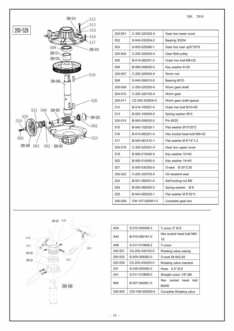
200-501 C-300-320302-0 Gear box lower cover
502 S-040-030204-0 Bearing 30204
503 S-005-020080-1 Gear box seal φ20*35*8
200-504 C-200-320500-0 Gear Belt pulley
505 B-014-080251-0 Outer hex bolt M8×25
506 B-065-006020-0 Key washer 6×20
200-507 C-200-320400-0 Worm rod
508 S-040-006010-0 Bearing 6010
200-509 C-200-320200-0 Worm gear shaft
200-510 C-200-320100-0 Worm gear
200-511 CZ-200-320600-0 Worm gear shaft spacer
512 B-014-100551-0 Outer hex bolt M10×55
513 B-050-100000-0 Spring washer Ø10
200-514 B-060-006020-0 Pin 6X20
515 B-040-102020-1 Flat washer Ø10*20*2
516 B-010-060201-0 Hex socket head bolt M6×20
517 B-040-061412-1 Flat washer Ø 6*14*1.2
200-518 C-300-320301-0 Gear box upper cover
519 B-065-010040-0 Key washer 10×40
520 B-065-014040-0 Key washer 14×40
521 S-000-030355-0 O-seal Ø 30*3.55
200-522 C-200-320700-0 Oil resistant seal
523 B-001-060001-0 Self-locking nut M6
524 B-050-080000-0 Spring washer Ø 8
525 B-040-083030-1 Flat washer Ø 8*30*3
200-526 CW-107-020001-0 Complete gear box
A04 S-015-000008-3 T-union 3* Ø 8
A44 B-010-060161-0 Hex socket head bolt M6×16
A48 S-017-010808-2 T-union
200-531 CX-200-430100-0 Rotating valve casing
200-532 S-000-059262-0 O-seal 59.9X2.62
200-535 CX-200-430200-0 Rotating valve mandrel
537 S-035-055080-0 Hose 5.5* Ø 8
A41 S-011-010808-0 Straight union 1/8"-Ø8
548 B-007-040061-0 Hex socket head bolt M4X6
200-540 CW-106-020000-0 Complete Rotating valve
200. 2018
- 17 –
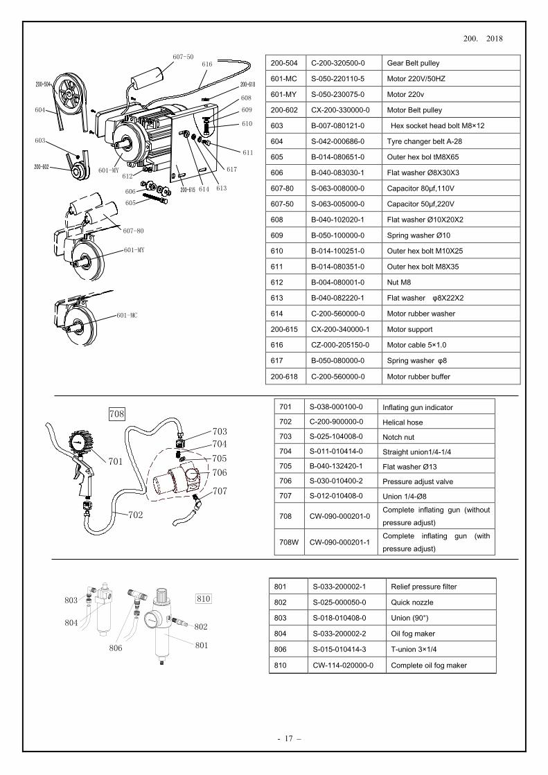
200-504 C-200-320500-0 Gear Belt pulley
601-MC S-050-220110-5 Motor 220V/50HZ
601-MY S-050-230075-0 Motor 220v
200-602 CX-200-330000-0 Motor Belt pulley
603 B-007-080121-0 Hex socket head bolt M8×12
604 S-042-000686-0 Tyre changer belt A-28
605 B-014-080651-0 Outer hex bol tM8X65
606 B-040-083030-1 Flat washer Ø8X30X3
607-80 S-063-008000-0 Capacitor 80μf,110V
607-50 S-063-005000-0 Capacitor 50μf,220V
608 B-040-102020-1 Flat washer Ø10X20X2
609 B-050-100000-0 Spring washer Ø10
610 B-014-100251-0 Outer hex bolt M10X25
611 B-014-080351-0 Outer hex bolt M8X35
612 B-004-080001-0 Nut M8
613 B-040-082220-1 Flat washer φ8X22X2
614 C-200-560000-0 Motor rubber washer
200-615 CX-200-340000-1 Motor support
616 CZ-000-205150-0 Motor cable 5×1.0
617 B-050-080000-0 Spring washer φ8
200-618 C-200-560000-0 Motor rubber buffer
701 S-038-000100-0 Inflating gun indicator
702 C-200-900000-0 Helical hose
703 S-025-104008-0 Notch nut
704 S-011-010414-0 Straight union1/4-1/4
705 B-040-132420-1 Flat washer Ø13
706 S-030-010400-2 Pressure adjust valve
707 S-012-010408-0 Union 1/4-Ø8
708 CW-090-000201-0 Complete inflating gun (without pressure adjust)
708W CW-090-000201-1 Complete inflating gun (with pressure adjust)
801 S-033-200002-1 Relief pressure filter
802 S-025-000050-0 Quick nozzle
803 S-018-010408-0 Union (90°)
804 S-033-200002-2 Oil fog maker
806 S-015-010414-3 T-union 3×1/4
810 CW-114-020000-0 Complete oil fog maker
200. 2018
- 18 -
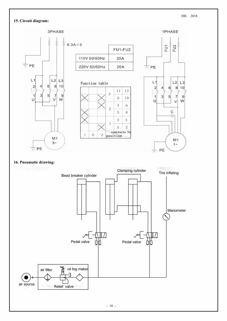
15. Circuit diagram:
16. Pneumatic drawing: