Rattlesnake Instr. Manual - Model Ship Kit, Ship - Filterbarn Shipways/Rattlesnake... · for...
48
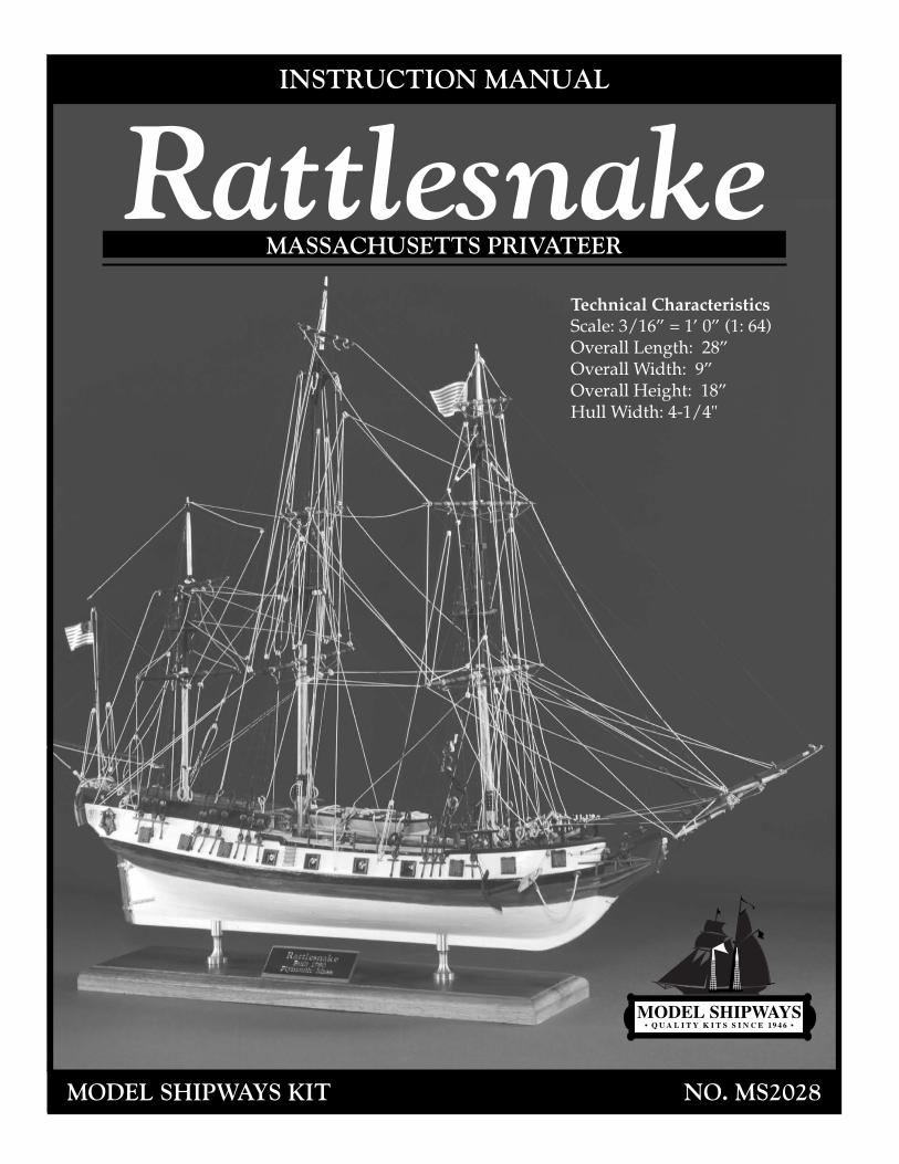
MODEL SHIPWAYS KIT NO. MS2028 INSTRUCTION MANUAL Technical Characteristics Scale: 3/16” = 1’ 0” (1: 64) Overall Length: 28” Overall Width: 9” Overall Height: 18” Hull Width: 4-1/4" Rattlesnake MASSACHUSETTS PRIVATEER
Transcript of Rattlesnake Instr. Manual - Model Ship Kit, Ship - Filterbarn Shipways/Rattlesnake... · for...
MODEL SHIPWAYS KIT NO. MS2028
INSTRUCTION MANUAL
Technical CharacteristicsScale: 3/16” = 1’ 0” (1: 64)Overall Length: 28”Overall Width: 9”Overall Height: 18”Hull Width: 4-1/4"
RattlesnakeMASSACHUSETTS PRIVATEER
Instruction Manual
Massachusetts Privateer
Rattlesnake1780
By George F. Campbell, 1963
Plank-On-Bulkhead Construction and ManualBy Ben Lankford, 1994
Model built by Bob Bruetsch
The Model Shipways Hull and Rigging plans for Rattlesnake were prepared in 1963 byMr. George F. Campbell, who passed away several years ago. Mr. Campbell was a notedBritish marine artist, author, naval architect, and historian. He was a member of theRoyal Institution of Naval Architects. One of his most noteworthy publications is ChinaTea Clippers. He also developed the drawings for the Cutty Sark restoration in Englandand authored Model Shipways' model handbook, Neophyte Shipmodeler's Jackstay.
The Model Shipways plans prepared by Mr. Campbell are based on Admiraltydraughts and a reconstruction originally published by Howard I. Chapelle in his book,The History of American Sailing Ships, and also The Search for Speed Under Sail. The rig-ging and deck equipment is based on contemporary texts.
The Model Shipways kit of Rattlesnake initially offered a solid hull model. This kit hasnow been converted to a Plank-On-Bulkhead type hull. The P-O-B hull plans wereprepared in 1994 by Ben Lankford along with this complete new instruction manual.
Copyright 1994Model Shipways
Sold & Distributed by Model Expo, a Division of Model Shipways, Inc.Hollywood, FL • www.modelexpo-online.com
2
Brief History
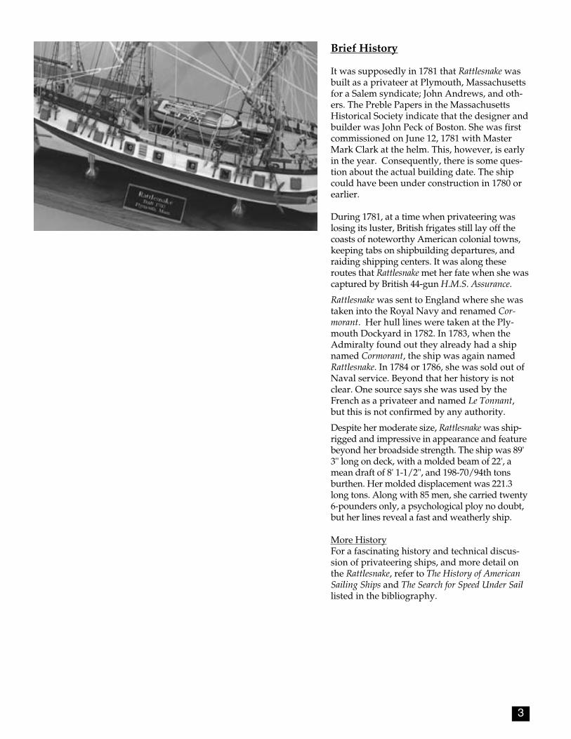
It was supposedly in 1781 that Rattlesnake wasbuilt as a privateer at Plymouth, Massachusettsfor a Salem syndicate; John Andrews, and oth-ers. The Preble Papers in the MassachusettsHistorical Society indicate that the designer andbuilder was John Peck of Boston. She was firstcommissioned on June 12, 1781 with MasterMark Clark at the helm. This, however, is earlyin the year. Consequently, there is some ques-tion about the actual building date. The shipcould have been under construction in 1780 orearlier.
During 1781, at a time when privateering waslosing its luster, British frigates still lay off thecoasts of noteworthy American colonial towns,keeping tabs on shipbuilding departures, andraiding shipping centers. It was along theseroutes that Rattlesnake met her fate when she wascaptured by British 44-gun H.M.S. Assurance.
Rattlesnake was sent to England where she wastaken into the Royal Navy and renamed Cor-morant. Her hull lines were taken at the Ply-mouth Dockyard in 1782. In 1783, when theAdmiralty found out they already had a shipnamed Cormorant, the ship was again namedRattlesnake. In 1784 or 1786, she was sold out ofNaval service. Beyond that her history is notclear. One source says she was used by theFrench as a privateer and named Le Tonnant,but this is not confirmed by any authority.
Despite her moderate size, Rattlesnake was ship-rigged and impressive in appearance and featurebeyond her broadside strength. The ship was 89'3" long on deck, with a molded beam of 22', amean draft of 8' 1-1/2", and 198-70/94th tonsburthen. Her molded displacement was 221.3long tons. Along with 85 men, she carried twenty6-pounders only, a psychological ploy no doubt,but her lines reveal a fast and weatherly ship.
More HistoryFor a fascinating history and technical discus-sion of privateering ships, and more detail onthe Rattlesnake, refer to The History of AmericanSailing Ships and The Search for Speed Under Saillisted in the bibliography.
3
4
CONSTRUCTION STAGES & TABLE OF CONTENTS
Brief History Pg 3Introduction/Credits Pg 2Before You Begin Pg 5What You'll Need to Start Construction Pg 5How to Work With the Plans & Parts Pg 6Painting & Staining the Model Pg 7
Stage A: Framing the Plank-On-Bulkhead Hull Pg 81. Bending Wood Pg 82. Center Keel Assembly Pg 83. Installing the Keel/Stem & Sternpost Pg 84. Cutting the Rabbet Pg 85. Installing the Bulkheads Pg 86. Installing the Transom Framing & Transom Pg 107. Installing the Bow & Stern Filler Blocks Pg 128. Covering the Mast Slots Pg 129. Installing the Gun Deck Waterway
& Upper Deck Covering Boards Pg 1210. Installing the Knightheads & Timerheads Pg 1211. Installing the Main, Forecastle
& Quarter Deck Rails Pg 1312. Installing the Forecastle
& Quarter Deck Breast Beams Pg 1313. Installing the Gunport Framing Pg 13
Stage B: Planking the Plank-On-Bulkhead Hull Pg 141. Getting Started Pg 142. Planking Battens & Belts Pg 143. Planking Butts Pg 144. Spiling Pg 155. Fastening the Planks Pg 156. Planking the Outer Hull Pg 157. Planking Inboard (Ceiling Planks) Pg 188. Planking the Decks Pg 18
Stage C: Completing the Basic Hull Structure Pg 191. Correcting & Sanding Pg 192. Building the Head Rails Pg 193. Gunport Lids Pg 194. Building the Gangways Pg 195. Natural Wood/Double Plank Option Pg 19
Stage D: Mounting the Hull Pg 201. Mounting Board with Two Pedestals Pg 20 2. Launching Ways Pg 21
Stage E: Adding the Hull Details Pg 211. Locating Deck Fittings & Structures Pg 212. Topsail Sheet Bitts, Fore Brace Bitts,
Riding Bitts & Gallows Bitts Pg 213. Ladders Pg 214. Hatches & Gratings Pg 215. Binnacle Pg 216. Capstan Pg 217. Catheads & Anchors Pg 218. Elm Pumps Pg 24
9. Kevels & Chesstrees Pg 2410. Galley Chimney Pg 2411. Channels Pg 2412. Deck Buckets Pg 2413. Eyebolts & Cleats Pg 2414. Rudder & Tiller Pg 2415. Quarter Badges Pg 2516. Cannons Pg 2517. Ship's Name Pg 2618. Ship's Longboat Pg 26
Stage F: Mast & Spar Construction Pg 271. The Importance of Scale Pg 272. Shaping & Tapering the Masts & Spars Pg 273. Building & Installing the Masts Pg 274. Building & Installing the Bowsprit & Jibboom Pg 295. Building the Lower, Crossjack, Topsail,
Topgallant & Spritsail Yards Pg 316. Building the Spanker Gaff & Boom Pg 31
Stage G: General Rigging & Sailmaking Information Pg 31Rigging Terms Defined1. Rigging Options Pg 312. Using the Rigging Plan Pg 323. Rigging Line & Block Sizes Pg 324. Treating the Lines Pg 335. Belaying Pins & Their Lines Pg 336. Rigging Tools Pg 347. Blocks & Deadeyes Pg 348. Sailmaking Pg 349. Rigging the Model Without Sails Pg 36
Stage H: Standing Rigging Pg 371. Shrouds Pg 372. Backstays Pg 373. Fore & Aft Stays Pg 374. Detail at the Tops Pg 375. Bowsprit Rigging Pg 376. Footropes Pg 37
Stage I: Running Rigging Pg 411. Fore Staysail, Fore Topmast Staysail & Jib Pg 412. Fore and Main Course,
& Mizzen Crossjack Yard Pg 413. Fore, Main & Mizzen Topsails Pg 414. Fore & Main Topgallant Sails Pg 435. Spanker Pg 436. Spritsail & Spritsail Topsail Pg 437. Miscellaneous Rigging Pg 43Final Touches Pg 43Scale Conversion Table Pg 44Rigging Line Diameters Pg 44Millimeters/Inches Conversion Chart Pg 44Bibliography Pg 45
5
The Rattlesnake is a very beautiful shipand makes a splendid model. Theplank-on-bulkhead hull constructionwith laser-cut parts offers a uniquebuilding experience. It assures an accu-rate hull form, and develops an under-standing of how real ships are con-structed.
The kit is supplied with a set of Britan-nia, brass, and wooden fittings to elim-inate problems in making or machin-ing such parts from scratch, whichmay be beyond the ability or resourcesof the average modeler. Many of thesefittings, however, will require final fin-ishing before they are suitable for in-stallation on the model. This will be es-pecially true for the Britannia fittingsand will be discussed later.
This kit will provide less experiencedmodelers with the opportunity to ac-quire some scratch-building tech-niques. As an aid, various techniqueswill appear throughout the instruc-tions. While the modeling progresses,you will see where you may want tosubstitute some of the kit fittings withyour own creations. By all means trythem, especially if you think you canimprove the model. The worst that canhappen is a little lost time. But, the ex-perience gained will be most valuablefor future projects.
If you are a beginner, take your time.This model has a fair amount of detailand small parts. Make sure you com-plete one stage before moving to thenext. When things go awry, considerdoing it over.
BEFORE YOU BEGIN
J. Finishing1. Paint Brushes
a. fine point for detailsb. 1/4" to 1/2" flat square for hull
K. Supplies(will be covered in detail in the Painting & Staining section and throughout the instructions)1. Paints2. Primer3. Stains and varnish4. White or Carpenter's (yellow)
wood glue5. Super glue6. Five-minute epoxy glue7. Wood filler
Note about glues: White glue, or Car-penter's wood glue (yellow in color; alsoavailable in tan color), will suffice formost of the model. Five-minute epoxyprovides extra strength for gluing fit-tings. Cyanoacrylate glue (super glue),such as Jet, can be used for quick adhe-sion and is ideal for adding a touch to arigging seizing to hold it in place. Thebest super glue for most applications isa medium viscosity gap filling type. Thewatery thin type is recommended to filla narrow crack by capillary action, andfor quickly securing hull planking to thebulkheads.
The following tools and supplies are rec-ommended for the construction process.Modelers who have built before mayhave their own favorites.
A. Knives1. Hobby knife2. No.11 blades
B. FilesSet of needle files
C. Clamps1. A few small C-clamps2. Wooden clothespins3. Rubber bands, #16 and #33
D. Tool SetA small carving tool set orindividual gouges and chisels for carving center keel rabbets, the counter block, stern and bow filler blocks, tapering the stem, and carving the ship's longboat.
E. Sharpening StoneNecessary to keep tools razor sharp
F. Boring Tools1. Set of miniature drills: #60 to #802. 1/16", 3/32", and 1/8" drills3. Pin vise
G. Miscellaneous1. Tack hammer2. Tweezers (a few)3. Small fine pointed scissors4. Miniature pliers
a. small roundb. flat nose
5. Bench vise (small)6. Soldering iron or torch
a. solderb. flux
7. Sewing thread (for seizing; other rigging in kit)a. blackb. tan
8. Beeswax block (for treating rigging lines)
9. 1/2" or 3/4" masking tape10. Wire cutters (for cutting fine
wire and strip metal)
H. SandpaperFine and medium grit garnet or aluminum oxide sandpaper (#100 to #220)
I. Sail clothLight weave cotton or linen cloth if you intend to add sails. A suitable cotton cloth is available from Model Expo.
WHAT YOU’LL NEED TO START CONSTRUCTION
6
You may need to make adjustments orallow for small differences in how yourmodel is shaping up; perhaps your masthas too much rake (the angle at which itsits). When lines go to belaying pointsthey should not drape over parts or con-flict with other lines. If necessary, move abelaying point or a fairlead. In otherwords, put yourself on the ship and useyour judgement.
3. Understanding Hull Lines Beginners may not be familiar with hulllines. Buttock lines are vertical longitu-dinal planes cut through the hull. Wa-terlines are horizontal planes, and sec-tions are transverse vertical planes. Allof these lines define the hull shape andare used by the draftsman to fair thehull form (create regular even curves).
A complete set of hull lines is shown onthe George Campbell plans but they arenot really needed for this particularmodel. With the plank-on-bulkheadconstruction, the laser-cut bulkheadsand center keel define the hull form.These are based on the Rattlesnake hulllines to outside of the planking, but aremade smaller to allow for the thicknesscreated by adding the planks.
4. Using Basswood LumberStandard cut basswood is available insheets and strips. Normally, thickness isavailable in 1/32", 1/16", 3/32", 1/8",5/32", 3/16", 1/4", and 1/2". Widths ofstrips are available in the same incre-ments. Sheets may be 1", 2", 3", or 4". Athickness of 3/64" is also a manufac-tured thickness, but not found in manycatalogs. However, if needed, it will beprovided in Model Shipways kits.
Note: Your kit may contain Europeanlimewood instead of the basswood mostof us are familiar with. For further infor-mation see the notes in the parts list.
For the model scale 3/16" = 1' 0", 1/64"is equal to 1" full ship size. 1/32" isequal to 2", and so on. Generally, theavailable sizes of basswood fit the fullship size quite well and the strips orsheets can be used directly. Occasional-ly, you will find a size where the stripmust be thinner than the basswood sizesupplied. In order to use a correct thick-ness, you will need to sand down a cer-tain thickness of basswood. This is easi-ly done with a sanding block beforemaking a part.
If you are fortunate enough to own apowered sanding thickness planer formodels, all the better. These can be pur-chased commercially. You can also make
Before starting model construction, ex-amine the kit and study the plans care-fully. Familiarizing yourself with the kitwill serve two purposes. First, it will letyou determine that all parts have beensupplied as listed. And second, you'll besurprised at just how quickly handlingthe parts allows you to better under-stand the kit requirements. Try to visu-alize how every part will look on thecompleted model. Also, determineahead of time what must be done first.The instructions will help you in this re-gard, but a thorough knowledge of theplans at the outset is essential.
It is suggested that all small fittings andhardware be sorted into labeled boxes orcompartments to avoid loss during thebuilding process.
1. The PlansFour Plan Sheets are provided:
1963 Plans by George Campbell:1. Hull Details and Lines Plan2. Rigging Plan
1994 Plans by Ben Lankford:3. Laser-Cut Wood Patterns4. Plank-On-Bulkhead Hull Construction
In addition, a set of sketches appearsthroughout this instruction manual tofurther illustrate the various stages ofconstruction.
The Rattlesnake kit is manufactured to ascale of 3/16" = 1' 0". Each plan sheet isdrawn to the exact scale that the modelis to be built, except where some detailshave been enlarged for clarity. Most di-mensions can be lifted directly off theplans by using a set of draftsman di-viders or by using a "tick" strip, which issimply a piece of paper used to "pickup" the dimensions (a roll of calculatortape works very well). Lay your paperstrip over the plan and mark the lengthsof items carefully with a sharp pencil.Then use the strip to transfer the marksto the wood or item to be made to scale. It is handy to have a triangular architect'sscale. Measuring and cutting parts usingthe 3/16" scale gives you a better feel forreal ship sizes. It also gives you a con-version for the full ship size dimensionsshown on the plans. At 3/16" scale, oneinch in full ship size equals 1/64". Keepthis in mind as you work. You will soonknow, for example, that if you see some-thing 4 inches wide full scale, yourmodel part will be 1/16".
2. Making Allowances Along the WayTry to be exact when following the plans,but use common sense along the way.
your own using a drum sander in a drillpress. Clamp a block alongside the sanderso the wood can be inserted between theblock and sander. It's a makeshift deal,but it works quite well.
It is a good idea to sort the wood con-tained in the kit by thickness. Whenbuilding a certain part, select a suitablesize from the proper thickness pile. Aftercutting what you need, return the remain-ing piece to that thickness pile. This savesa lot of time looking for a given thickness.Don't worry about using a piece for oneitem that was intended for another. It willall come out in the wash. There is enoughextra wood in the kit so you should notrun out before you complete the model.
5. Cast-Metal FittingsThe kit is supplied with Britannia metalcastings. The Britannia metal is a greatimprovement over the white metal thatwas used in some older kits. Unlikewhite metal and pewter, Britannia doesnot contain lead, so there are no possiblecorrosion problems. Many of these fit-tings, however, will require final finish-ing before they are suitable for installingon the model.
Before painting the cast-metal fittings,clean them up by removing all the mold-joint flash. To do this, use a No. 11hobby blade to cut the flash, then file orsand with fine sandpaper. It is also sug-gested that you clean the fittings thor-oughly with warm soapy water beforeapplying primer. Make sure they arerinsed thoroughly and allowed to drybefore painting.
6. Soldering & Working with Brass The Rattlesnake is a ship from a periodthat had very little iron fittings. Conse-quently, you will not be required to domuch soldering, if any. Gudgeons, pin-tles, and chain plates could be solderedor simply glued. If you do solder, the se-cret is to keep the parts to be solderedclean, and keep the end of your solderingiron clean and well tinned. File or sandthe parts, then keep your fingers off. Heatthe parts first, then touch the solder. Fileoff any excess solder.
HOW TO WORK WITH THE PLANS & PARTS

7
It may seem strange to begin an instruc-tion manual with directions on applyingthe finishes to the model. Not so! Muchtime and effort can be saved, and a moreprofessional result can be obtained, ifthe finishing process is carried out dur-ing construction. Proper timing in appli-cation of finishes and the use of maskingtape to define painted edges shouldeliminate unsightly glue marks andsplotchy stained surfaces. In the end,following these general suggestions willbe to your advantage.
PaintUse a flat-finish paint such as the modelpaints made by Floquil, Polly-S, Testors,Humbrol, and Model Masters. Youcould also use artist's paints by Jo Sonja(used by many bird carvers) or HolbeinAcryla Gouache. These paints are acombination acrylic-gouache.
Paint ColorsThe recommended color scheme for theRattlesnake is as follows:
Topside Rails: Yellow Ochre
Quarter Deck Outboard BulwarkPlanking between Rails: Black
Outboard Planking from Rails down tothe top of Wales: Yellow Ochre
A Parallel Band about 1/2" wide fromtop of the Wales, and including theUpper part of the Stem: Black
Head Rails: Yellow Ochre
Hull Bottom below the Black Band:White or Tallow (or lighter tallow pluswhite). Note: Tallow is an ivory colorand is available pre-mixed in Floquilmodel paint available from Model Expo.
Stern Window Frames: White
Center Dummy Window Panes: PaleBlue
Figurehead: Any bright colors
Bulwarks Inboard: Grey
Decking: Natural light Tan or Greystain with low sheen varnish
Masts, Spars and Deck Bitts: Burnt Si-enna stain, or any Tan/Maple coloredstain with low sheen varnish
Tops & Doublings (top up and includ-ing mast caps), and Bands around Foreand Main Mast: Black
Longboat: Tallow or White bottom, Nat-ural varnished sides and interior (Tan orMaple stain), Black outboard moldingand Red spray rail
Ironwork: Black
Standing Rigging: Tarred (Black orDark Brown)
Running Rigging: Tan or WeatheredGrey
PrimerUse a Grey primer. Floquil is excellent.The Grey color will highlight sandingscratches and other defects better thanWhite primer. Prime all woodwork to bepainted, and prime all metal fittings.Lightly sand the primed items. Use aspackling compound, such as Pic-n-Patch brand, to fill any scratches and de-fects, then re-prime. Careful! Do notprime parts to be stained or varnished.
Stains & FinishesFor natural finished wood, use a protec-tive coating after staining such as lowsheen polyurethane varnish or the Flo-quil coatings. You can also use an oil-resin mix such as natural Minwax. Flo-quil stain, or Minwax stains can be usedto tone the wood.
Brushes & ProceduresUse good quality soft sable or synthetichair artist brushes. A small pointedbrush is good for details. For the mainhull areas, use a 1/4- to 1/2-inch flatbrush.
Before painting, clean the model with atack rag. Apply your paint in smootheven strokes, overlapping the strokes asyou go. Thin the paint enough to elimi-nate brush strokes, but not run. You willneed four or five coats of the light colorsto cover the Grey primer, and maybeonly two coats of the dark. Check yourfinish between coats, and sand or addspackle as necessary to get rid of anyblemishes.
Anywhere two colors meet, use maskingtape. Electrician's black plastic tape isideal. It leaves a nice edge and is notoverly sticky. Do not use drafting tape.The edges are wrinkled and paint mayrun under them.
PAINTING & STAINING THE MODEL
8
STAGE AFRAMING THE PLANK-ON-BULKHEAD HULL
1. Bending WoodBuilding a P-O-B hull requires somewood bending and twisting, and thewood must remain in the desired posi-tion so as not to put too much stress onglue joints and fasteners. The term"steam-bent" will be used throughoutthe text whenever such a process is nec-essary. However, here are three ways tobend wood.
Steam-bending - For actual steam-bend-ing, hold the piece over a kettle ofsteaming water and bend. Hold thewood in position until it cools. It shouldremain nearly in that position, but mayspring back slightly.
Soaking - Another method is to soak thepiece in warm water for several hours.Try adding a little household ammoniato the water. You can also use pure am-monia. This speeds up the soaking pro-cess and makes the wood fibers slipperyso the wood is easily bent. Hold thewood in position with a form after soak-ing and let it dry completely.
Hot iron - You may also bend woodquickly over a soldering iron, but don'tlet it get too hot. A large soldering ironwith a tubular end is ideal. The tube nearthe handle is not as hot as the very end.It is also possible to purchase modelplank-bending irons commercially. Theyare designed for controlled heat.
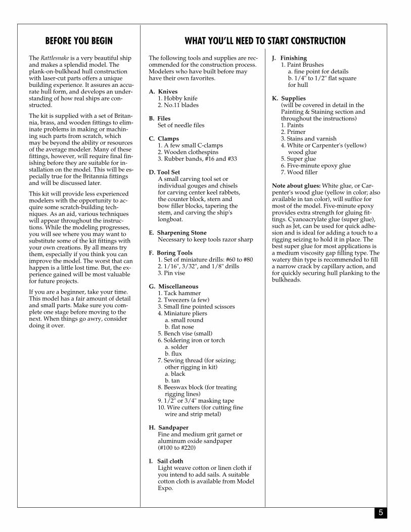
2. Center Keel AssemblyThe first step in constructing the hull isto assemble the two laser-cut center keelpieces. First, use a sharp pencil andmark the bulkhead locations below theslots and the WL reference line. Thisline is used to locate Bulkheads "A"through "M" on the center keel. Mark onboth sides of each center keel piece. Beespecially critical in locating the refer-ence line. Measure from several pointsfrom the plans. The reference line is akey to proper alignment.
Place the two parts, 1 and 2, over a sheetof wax paper or plastic wrap, on a flatbuilding board or table. Glue the jointwith white or carpenter's wood glue.Use a steel or aluminum straight edgeto align the WL reference line. Place aweight on each piece to hold it downwhile the glue dries. Let the glue dry atleast overnight, preferably 24 hours (seefigure 1).
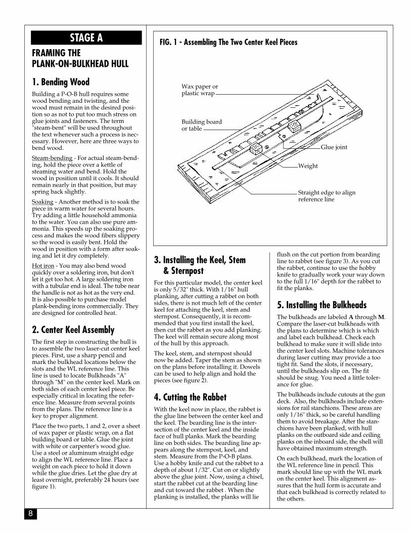
3. Installing the Keel, Stem & Sternpost
For this particular model, the center keelis only 5/32" thick. With 1/16" hullplanking, after cutting a rabbet on bothsides, there is not much left of the centerkeel for attaching the keel, stem andsternpost. Consequently, it is recom-mended that you first install the keel,then cut the rabbet as you add planking.The keel will remain secure along mostof the hull by this approach.
The keel, stem, and sternpost shouldnow be added. Taper the stem as shownon the plans before installing it. Dowelscan be used to help align and hold thepieces (see figure 2).
4. Cutting the RabbetWith the keel now in place, the rabbet isthe glue line between the center keel andthe keel. The bearding line is the inter-section of the center keel and the insideface of hull planks. Mark the beardingline on both sides. The bearding line ap-pears along the sternpost, keel, andstem. Measure from the P-O-B plans.Use a hobby knife and cut the rabbet to adepth of about 1/32". Cut on or slightlyabove the glue joint. Now, using a chisel,start the rabbet cut at the bearding lineand cut toward the rabbet . When theplanking is installed, the planks will lie
flush on the cut portion from beardingline to rabbet (see figure 3). As you cutthe rabbet, continue to use the hobbyknife to gradually work your way downto the full 1/16" depth for the rabbet tofit the planks.
5. Installing the BulkheadsThe bulkheads are labeled A through M.Compare the laser-cut bulkheads withthe plans to determine which is whichand label each bulkhead. Check eachbulkhead to make sure it will slide intothe center keel slots. Machine tolerancesduring laser cutting may provide a tootight fit. Sand the slots, if necessary,until the bulkheads slip on. The fitshould be snug. You need a little toler-ance for glue.
The bulkheads include cutouts at the gundeck. Also, the bulkheads include exten-sions for rail stanchions. These areas areonly 1/16" thick, so be careful handlingthem to avoid breakage. After the stan-chions have been planked, with hullplanks on the outboard side and ceilingplanks on the inboard side, the shell willhave obtained maximum strength.
On each bulkhead, mark the location ofthe WL reference line in pencil. Thismark should line up with the WL markon the center keel. This alignment as-sures that the hull form is accurate andthat each bulkhead is correctly related tothe others.
FIG. 1 - Assembling The Two Center Keel Pieces
Wax paper orplastic wrap
Building boardor table
Glue joint
Weight
Straight edge to alignreference line
9
FIG. 4 - Shaping The Bulkheads FIG. 5 - Installing The Bulkheads
Next, mark the bevels on the bulkheads.Use a tick strip to transfer the bevel lineas shown on the plans, or cut the bulk-head patterns from the plan and gluethem onto the bulkheads. You can alsolay the patterns over the bulkheads anduse a pin prick to locate the bevels. Cutthe bevels with a #11 hobby knife bladeas shown (see figure 4).
Some of the bevels are very slight, espe-cially the deck bevels and the sidebevels near amidships. These slightbevels are not drawn because they arehardly measurable. They can be sandedafter the bulkheads are installed insteadof pre-cutting them.
Glue the bulkheads in place, makingsure that the WL marks on the bulk-heads and the center keel line up. Use asquare to make each bulkhead perpen-dicular to the center keel, then tack atemporary strip to the top to hold thebulkhead in place while the glue dries(see figure 5).
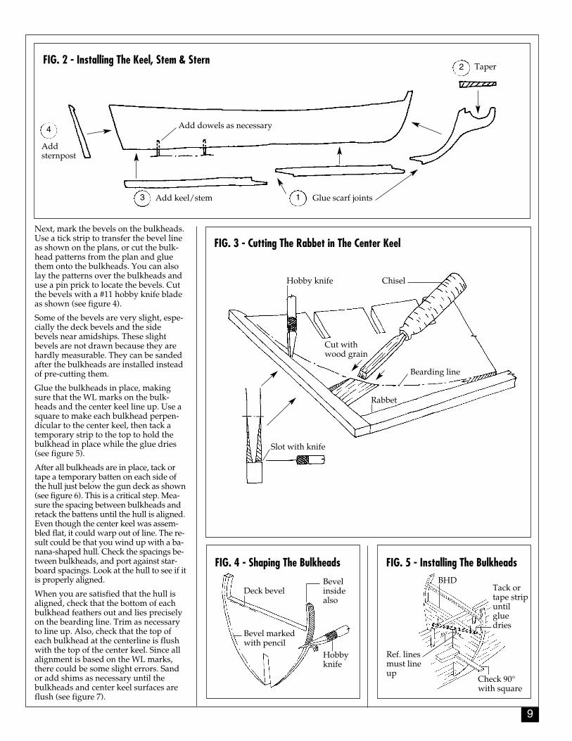
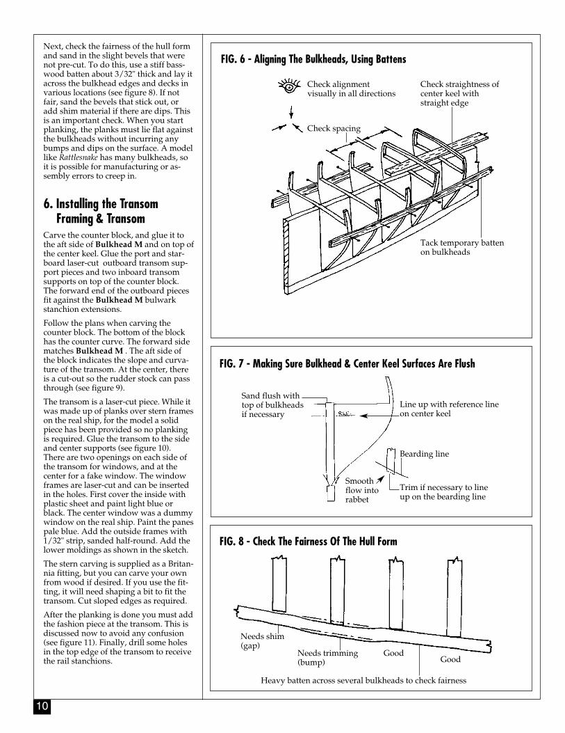
After all bulkheads are in place, tack ortape a temporary batten on each side ofthe hull just below the gun deck as shown(see figure 6). This is a critical step. Mea-sure the spacing between bulkheads andretack the battens until the hull is aligned.Even though the center keel was assem-bled flat, it could warp out of line. The re-sult could be that you wind up with a ba-nana-shaped hull. Check the spacings be-tween bulkheads, and port against star-board spacings. Look at the hull to see if itis properly aligned.
When you are satisfied that the hull isaligned, check that the bottom of eachbulkhead feathers out and lies preciselyon the bearding line. Trim as necessaryto line up. Also, check that the top ofeach bulkhead at the centerline is flushwith the top of the center keel. Since allalignment is based on the WL marks,there could be some slight errors. Sandor add shims as necessary until thebulkheads and center keel surfaces areflush (see figure 7).
FIG. 2 - Installing The Keel, Stem & Stern
FIG. 3 - Cutting The Rabbet in The Center Keel
Add dowels as necessary
Taper
Glue scarf jointsAdd keel/stem
Addsternpost
1
2
3
4
Cut withwood grain
Rabbet
Bearding line
Slot with knife
ChiselHobby knife
Hobbyknife
Bevelinsidealso
Deck bevel
Bevel markedwith pencil
BHDTack ortape stripuntilgluedries
Check 90°with square
Ref. linesmust lineup
10
Next, check the fairness of the hull formand sand in the slight bevels that werenot pre-cut. To do this, use a stiff bass-wood batten about 3/32" thick and lay itacross the bulkhead edges and decks invarious locations (see figure 8). If notfair, sand the bevels that stick out, oradd shim material if there are dips. Thisis an important check. When you startplanking, the planks must lie flat againstthe bulkheads without incurring anybumps and dips on the surface. A modellike Rattlesnake has many bulkheads, soit is possible for manufacturing or as-sembly errors to creep in.
6. Installing the Transom Framing & Transom
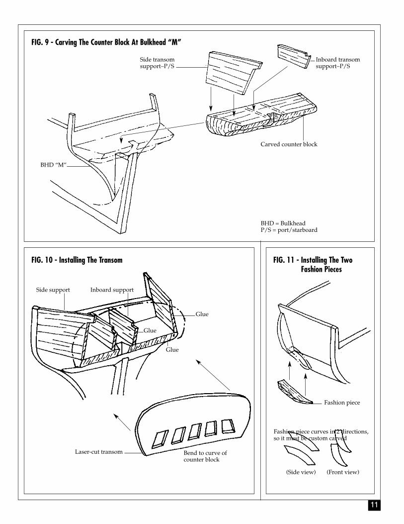
Carve the counter block, and glue it tothe aft side of Bulkhead M and on top ofthe center keel. Glue the port and star-board laser-cut outboard transom sup-port pieces and two inboard transomsupports on top of the counter block.The forward end of the outboard piecesfit against the Bulkhead M bulwarkstanchion extensions.
Follow the plans when carving thecounter block. The bottom of the blockhas the counter curve. The forward sidematches Bulkhead M . The aft side ofthe block indicates the slope and curva-ture of the transom. At the center, thereis a cut-out so the rudder stock can passthrough (see figure 9).
The transom is a laser-cut piece. While itwas made up of planks over stern frameson the real ship, for the model a solidpiece has been provided so no plankingis required. Glue the transom to the sideand center supports (see figure 10). There are two openings on each side ofthe transom for windows, and at thecenter for a fake window. The windowframes are laser-cut and can be insertedin the holes. First cover the inside withplastic sheet and paint light blue orblack. The center window was a dummywindow on the real ship. Paint the panespale blue. Add the outside frames with1/32" strip, sanded half-round. Add thelower moldings as shown in the sketch.
The stern carving is supplied as a Britan-nia fitting, but you can carve your ownfrom wood if desired. If you use the fit-ting, it will need shaping a bit to fit thetransom. Cut sloped edges as required.
After the planking is done you must addthe fashion piece at the transom. This isdiscussed now to avoid any confusion(see figure 11). Finally, drill some holesin the top edge of the transom to receivethe rail stanchions.
FIG. 6 - Aligning The Bulkheads, Using Battens
FIG. 7 - Making Sure Bulkhead & Center Keel Surfaces Are Flush
FIG. 8 - Check The Fairness Of The Hull Form
Check alignment visually in all directions
Check spacing
Check straightness ofcenter keel withstraight edge
Tack temporary battenon bulkheads
Sand flush withtop of bulkheadsif necessary
Line up with reference lineon center keel
Bearding line
Trim if necessary to lineup on the bearding line
Smoothflow intorabbet
Needs shim(gap)
Needs trimming(bump)
GoodGood
Heavy batten across several bulkheads to check fairness
11
FIG. 10 - Installing The Transom FIG. 11 - Installing The Two Fashion Pieces
FIG. 9 - Carving The Counter Block At Bulkhead “M”
Carved counter block
Inboard transomsupport–P/S
Side transomsupport–P/S
BHD “M”
Side support Inboard support
Glue
Glue
Glue
Laser-cut transom Bend to curve ofcounter block
Fashion piece
Fashion piece curves in 2 directions, so it must be custom carved
(Side view) (Front view)
BHD = BulkheadP/S = port/starboard
12
7. Installing the Bow & Stern Filler Blocks
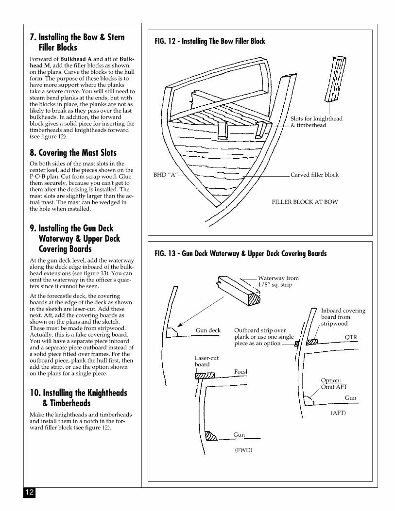
Forward of Bulkhead A and aft of Bulk-head M, add the filler blocks as shownon the plans. Carve the blocks to the hullform. The purpose of these blocks is tohave more support where the plankstake a severe curve. You will still need tosteam bend planks at the ends, but withthe blocks in place, the planks are not aslikely to break as they pass over the lastbulkheads. In addition, the forwardblock gives a solid piece for inserting thetimberheads and knightheads forward(see figure 12).
8. Covering the Mast SlotsOn both sides of the mast slots in thecenter keel, add the pieces shown on theP-O-B plan. Cut from scrap wood. Gluethem securely, because you can't get tothem after the decking is installed. Themast slots are slightly larger than the ac-tual mast. The mast can be wedged inthe hole when installed.
9. Installing the Gun Deck Waterway & Upper Deck Covering Boards
At the gun deck level, add the waterwayalong the deck edge inboard of the bulk-head extensions (see figure 13). You canomit the waterway in the officer's quar-ters since it cannot be seen.
At the forecastle deck, the coveringboards at the edge of the deck as shownin the sketch are laser-cut. Add thesenext. Aft, add the covering boards asshown on the plans and the sketch.These must be made from stripwood.Actually, this is a fake covering board.You will have a separate piece inboardand a separate piece outboard instead ofa solid piece fitted over frames. For theoutboard piece, plank the hull first, thenadd the strip, or use the option shownon the plans for a single piece.
10. Installing the Knightheads & Timberheads
Make the knightheads and timberheadsand install them in a notch in the for-ward filler block (see figure 12).
FIG. 12 - Installing The Bow Filler Block
FIG. 13 - Gun Deck Waterway & Upper Deck Covering Boards
Slots for knighthead & timberhead
Carved filler block
FILLER BLOCK AT BOW
BHD “A”
Waterway from 1/8” sq. strip
Gun deck
Laser-cutboard
Focsl
Gun
(FWD)
Inboard coveringboard from stripwood
QTROutboard strip overplank or use one singlepiece as an option
Option: Omit AFT
(AFT)
Gun
13
11. Installing the Main, Forecastle & Quarter Deck Rails
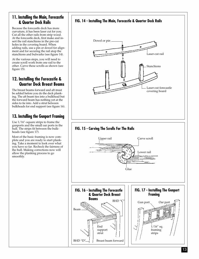
Because the forecastle deck has morecurvature, it has been laser cut for you.Cut all the other rails from strip wood.At the forecastle deck, first make and in-sert the rail stanchions in the pre-cutholes in the covering board. Whenadding rails, use a pin or dowel for align-ment and for securing the rail atop thestanchions and bulwarks (see figure 14).
At the various steps, you will need tocreate scroll work from one rail to theother. Carve these scrolls as shown (seefigure 15).
12. Installing the Forecastle & Quarter Deck Breast Beams
The breast beams forward and aft mustbe added before you do the deck plank-ing. The aft beam ties into a bulkhead butthe forward beam has nothing yet at thesides to tie into. Add a strut betweenbulkheads for end support (see figure 16).
13. Installing the Gunport FramingUse 1/16"–square strips to frame thegunports and the small oar ports in thehull. The strips fit between the bulk-heads (see figure 17).
Most of the basic framing is now com-plete and you are ready to start plank-ing. Take a moment to look over whatyou have so far. Recheck the fairness ofthe hull. Making corrections now willallow the planking process to gosmoothly.
FIG. 14 - Installing The Main, Forecastle & Quarter Deck Rails
FIG. 16 - Installing The Forecastle& Quarter Deck Breast Beams
FIG. 17 - Installing The Gunport Framing
FIG. 15 - Carving The Scrolls For The Rails
Dowel or pin
Laser-cut rail
Stanchions
Laser-cut forecastlecovering board
Upper rail Carve scroll
Lower rail
Glue
Beam
BHD “C”
End supportstrut
Breast beam forwardBHD “D”
Gun port
1/16” sq.framingstrips
Oar port
14
STAGE BPlanking the Plank-On-Bulkhead HullBefore getting started, it 's a good ideato know some of the more commonshipbuilding terms that apply to theplanking process. Consider the follow-ing few key words as you work:
1. A plank is a single length of woodused for planking a hull or deck. Aplanking strake is a continuous line ofplanks, butted against each other frombow to stern, or wherever the strake be-gins or ends.
2. A garboard strake is that strake ofplanking adjacent to the keel.
3. The sheer strake is the uppermostmain hull strake.
4. The wale is a heavy layer of strakesbelow the sheer strake along the hull'sside. For the Rattlesnake the upper edgeof the wale protrudes beyond the plank-ing above. However, there is no lowerwale edge. The heavier wale planksgradually taper into the lower plankingso the hull surface is flush from the topedge of the wale down to the keel rabbet.
5. When discussing planking belts, weare talking about a group of planksalong the hull. Belts are laid out usingbattens, which are temporary strips offlexible wood used to locate the belt. Aribband is also a batten, used on boatsand ships to hold the frames in placewhile the planking is being added. Rib-bands are removed as the planking iscompleted.
6. Spiling is a term used to describe aprocess for marking and cutting a plankto a given shape.
7. Edge bending, also called springing, iswhen you bend a plank edgewise.
8. When planking, the use of the wordfair refers to smooth, gradual curves.
9. Nib or nibbing is where one plank runsinto another at a sharp angle. In order toeliminate the feathered edge, the plankis cut off on the end and it is fitted into asimilar cut in the other plank. Nibbing isgenerally applied to decks, but hullplanks also can be nibbed.
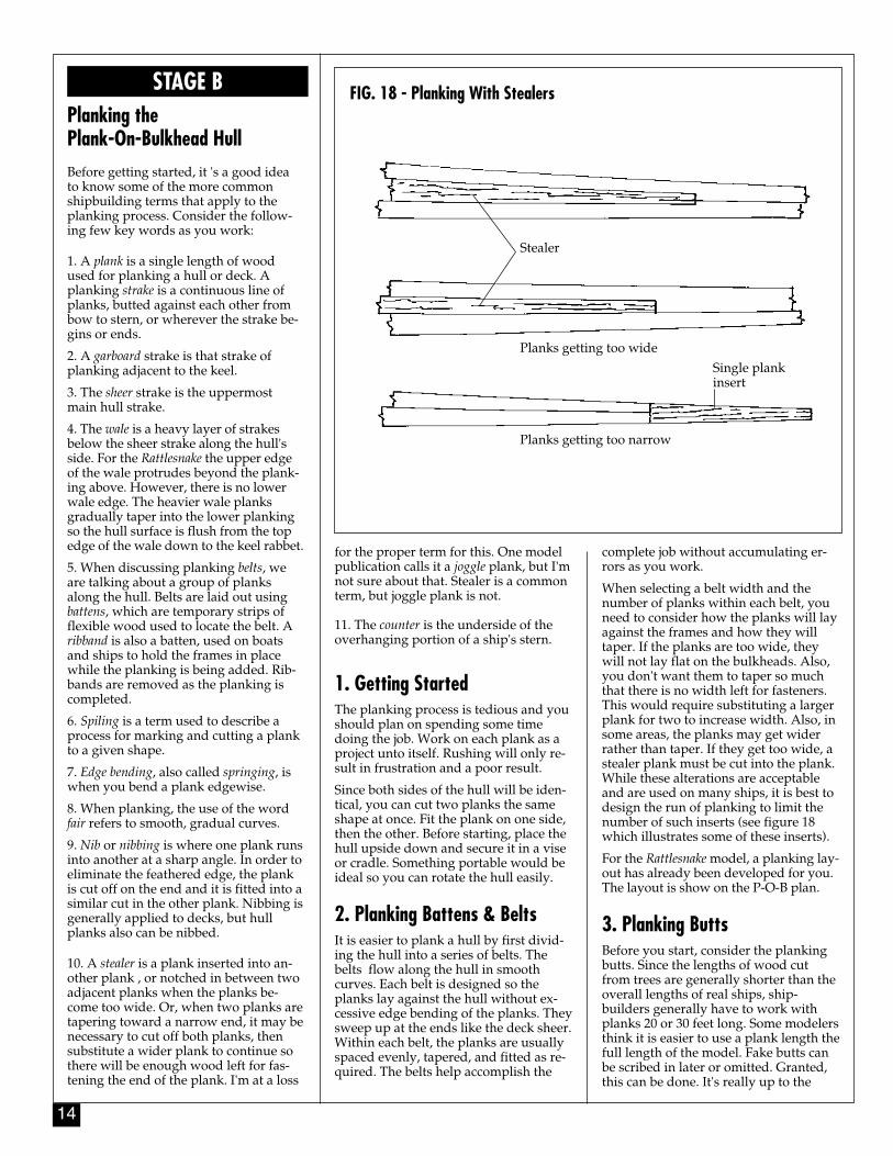
10. A stealer is a plank inserted into an-other plank , or notched in between twoadjacent planks when the planks be-come too wide. Or, when two planks aretapering toward a narrow end, it may benecessary to cut off both planks, thensubstitute a wider plank to continue sothere will be enough wood left for fas-tening the end of the plank. I'm at a loss
for the proper term for this. One modelpublication calls it a joggle plank, but I'mnot sure about that. Stealer is a commonterm, but joggle plank is not.
11. The counter is the underside of theoverhanging portion of a ship's stern.
1. Getting StartedThe planking process is tedious and youshould plan on spending some timedoing the job. Work on each plank as aproject unto itself. Rushing will only re-sult in frustration and a poor result.
Since both sides of the hull will be iden-tical, you can cut two planks the sameshape at once. Fit the plank on one side,then the other. Before starting, place thehull upside down and secure it in a viseor cradle. Something portable would beideal so you can rotate the hull easily.
2. Planking Battens & BeltsIt is easier to plank a hull by first divid-ing the hull into a series of belts. Thebelts flow along the hull in smoothcurves. Each belt is designed so theplanks lay against the hull without ex-cessive edge bending of the planks. Theysweep up at the ends like the deck sheer.Within each belt, the planks are usuallyspaced evenly, tapered, and fitted as re-quired. The belts help accomplish the
complete job without accumulating er-rors as you work.
When selecting a belt width and thenumber of planks within each belt, youneed to consider how the planks will layagainst the frames and how they willtaper. If the planks are too wide, theywill not lay flat on the bulkheads. Also,you don't want them to taper so muchthat there is no width left for fasteners.This would require substituting a largerplank for two to increase width. Also, insome areas, the planks may get widerrather than taper. If they get too wide, astealer plank must be cut into the plank.While these alterations are acceptableand are used on many ships, it is best todesign the run of planking to limit thenumber of such inserts (see figure 18which illustrates some of these inserts).
For the Rattlesnake model, a planking lay-out has already been developed for you.The layout is show on the P-O-B plan.
3. Planking ButtsBefore you start, consider the plankingbutts. Since the lengths of wood cutfrom trees are generally shorter than theoverall lengths of real ships, ship-builders generally have to work withplanks 20 or 30 feet long. Some modelersthink it is easier to use a plank length thefull length of the model. Fake butts canbe scribed in later or omitted. Granted,this can be done. It's really up to the
FIG. 18 - Planking With Stealers
Stealer
Planks getting too wide
Single plankinsert
Planks getting too narrow
15
modeler. However, by using shorterpieces there are some advantages. Sinceall planks taper to some degree, usingthe shorter piece will let you mark thetaper quick, and the plank will be easierto fasten in place. And with a shortpiece, only one hand is necessary to holdit down. Also, if you make a mistake,you only have a small piece to do over.So, the following is based on the use ofthe shorter lengths.
Planking butts will not be exactly like areal ship. Because the model is built onthe bulkhead system, planking buttsmust occur on bulkheads.
Use a plank length to cover four bulk-head spaces. This is a comfortable lengthto handle for this model; about 5" to 6".To scale, that's a plank 27 to 32 feet long.However, to avoid having very shortpieces at the bow and stern, you mayneed to use a longer or shorter plank tocomplete the run.
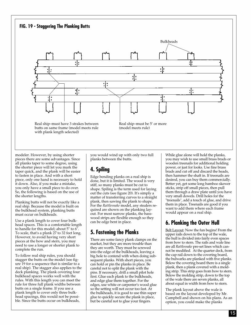
To follow real ship rules, you shouldstagger the butts on the model (see fig-ure 19 for a sequence that is similar to areal ship). The stagger also applies to thedeck planking. The plank covering fourbulkhead spaces works well with therules. With this length you can meet therule for three full plank widths betweenbutts on a single frame. If you use aplank length to cover only three bulk-head spacings, this would not be possi-ble. Since the butts occur on bulkheads,
you would wind up with only two fullplanks between the butts.
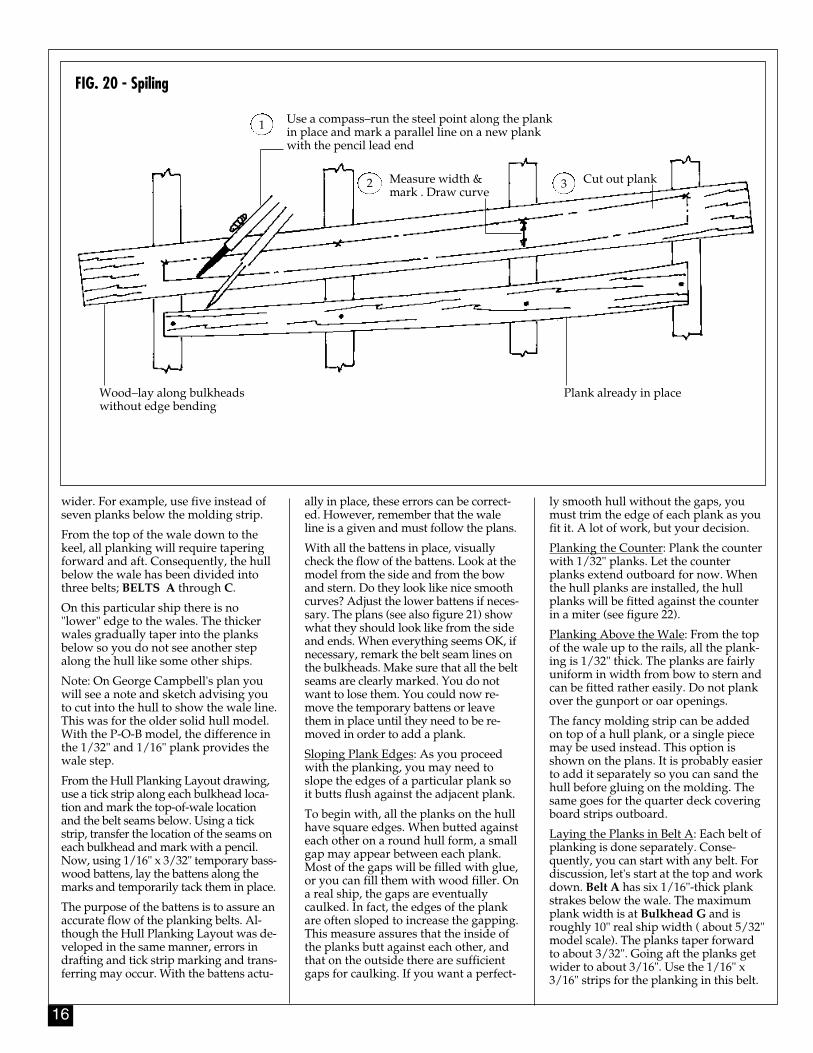
4. SpilingEdge bending planks on a real ship isdone, but it is limited. The wood is verystiff, so many planks must be cut toshape. Spiling is the term used for layingout the cuts (see figure 20). It's simply amatter of transferring curves to a straightplank, then sawing the plank to shape.For the Rattlesnake model, any stealers re-quired are shown on the planking lay-out. For most narrow planks, the bass-wood strips are flexible enough so theycan be edge bent in place.
5. Fastening the PlanksThere are some fancy plank clamps on themarket, but they are more trouble thanthey are worth. They must be screwedinto the edge of the bulkheads, leaving abig hole to contend with when doing sub-sequent planks. With short pieces, youcan hold or pin the planks in place. Becareful not to split the plank with thepins. If necessary, drill a small pilot holefirst. Glue each plank to the bulkheads,and edge glue them together. For theedges, use white or carpenter's wood glueso the setting will not occur too fast. Atthe bulkheads, it is good to use thin superglue to quickly secure the plank in place,but be careful not to glue your fingers.
While glue alone will hold the planks,you may wish to use small brass brads orwooden treenails for additional holdingpower, or just for looks. Use fine brassbrads and cut off and discard the heads,then hammer the shaft in. If treenails aredesired, you can buy them commercially.Better yet, get some long bamboo skewersticks, strip off small pieces, then pullthem through a draw plate until you havevery small dowels. Drill holes for the"treenails", add a touch of glue, and drivethem in place. Treenails are good if youwant to add them where each framewould appear on a real ship.
6. Planking the Outer HullBelt Layout: Now the fun begins! From theupper rails down to the top of the wale,the hull is divided into fairly even spacesfrom bow to stern. The rails and wale lineare all Rattlesnake pre-set lines which can-not be modified. At the quarter deck, fromthe cap rail down to the covering board,the bulwarks are planked with five planks.Below the covering board there is a singleplank, then a plank covered with a mold-ing strip. This strip goes from bow to stern.Below the molding strip, down to the topof the wale there are seven planks, allabout equal in width from bow to stern.
The plank layout above the wale isbased on the layout developed by Mr.Campbell and shown on his plans. As anoption, you could make the planks
FIG. 19 - Staggering The Planking Butts
Bulkheads
Real ship–must be 5’ or more (model meets rule)
Real ship–must have 3 strakes betweenbutts on same frame (model meets rulewith plank length selected)
16
wider. For example, use five instead ofseven planks below the molding strip.
From the top of the wale down to thekeel, all planking will require taperingforward and aft. Consequently, the hullbelow the wale has been divided intothree belts; BELTS A through C.
On this particular ship there is no"lower" edge to the wales. The thickerwales gradually taper into the planksbelow so you do not see another stepalong the hull like some other ships.
Note: On George Campbell's plan youwill see a note and sketch advising youto cut into the hull to show the wale line.This was for the older solid hull model.With the P-O-B model, the difference inthe 1/32" and 1/16" plank provides thewale step.
From the Hull Planking Layout drawing,use a tick strip along each bulkhead loca-tion and mark the top-of-wale locationand the belt seams below. Using a tickstrip, transfer the location of the seams oneach bulkhead and mark with a pencil.Now, using 1/16" x 3/32" temporary bass-wood battens, lay the battens along themarks and temporarily tack them in place.
The purpose of the battens is to assure anaccurate flow of the planking belts. Al-though the Hull Planking Layout was de-veloped in the same manner, errors indrafting and tick strip marking and trans-ferring may occur. With the battens actu-
ally in place, these errors can be correct-ed. However, remember that the waleline is a given and must follow the plans.
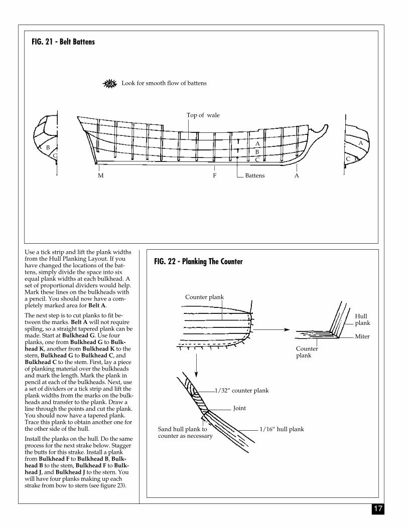
With all the battens in place, visuallycheck the flow of the battens. Look at themodel from the side and from the bowand stern. Do they look like nice smoothcurves? Adjust the lower battens if neces-sary. The plans (see also figure 21) showwhat they should look like from the sideand ends. When everything seems OK, ifnecessary, remark the belt seam lines onthe bulkheads. Make sure that all the beltseams are clearly marked. You do notwant to lose them. You could now re-move the temporary battens or leavethem in place until they need to be re-moved in order to add a plank.
Sloping Plank Edges: As you proceedwith the planking, you may need toslope the edges of a particular plank soit butts flush against the adjacent plank.
To begin with, all the planks on the hullhave square edges. When butted againsteach other on a round hull form, a smallgap may appear between each plank.Most of the gaps will be filled with glue,or you can fill them with wood filler. Ona real ship, the gaps are eventuallycaulked. In fact, the edges of the plankare often sloped to increase the gapping.This measure assures that the inside ofthe planks butt against each other, andthat on the outside there are sufficientgaps for caulking. If you want a perfect-
ly smooth hull without the gaps, youmust trim the edge of each plank as youfit it. A lot of work, but your decision.
Planking the Counter: Plank the counterwith 1/32" planks. Let the counterplanks extend outboard for now. Whenthe hull planks are installed, the hullplanks will be fitted against the counterin a miter (see figure 22).
Planking Above the Wale: From the topof the wale up to the rails, all the plank-ing is 1/32" thick. The planks are fairlyuniform in width from bow to stern andcan be fitted rather easily. Do not plankover the gunport or oar openings.
The fancy molding strip can be addedon top of a hull plank, or a single piecemay be used instead. This option isshown on the plans. It is probably easierto add it separately so you can sand thehull before gluing on the molding. Thesame goes for the quarter deck coveringboard strips outboard.
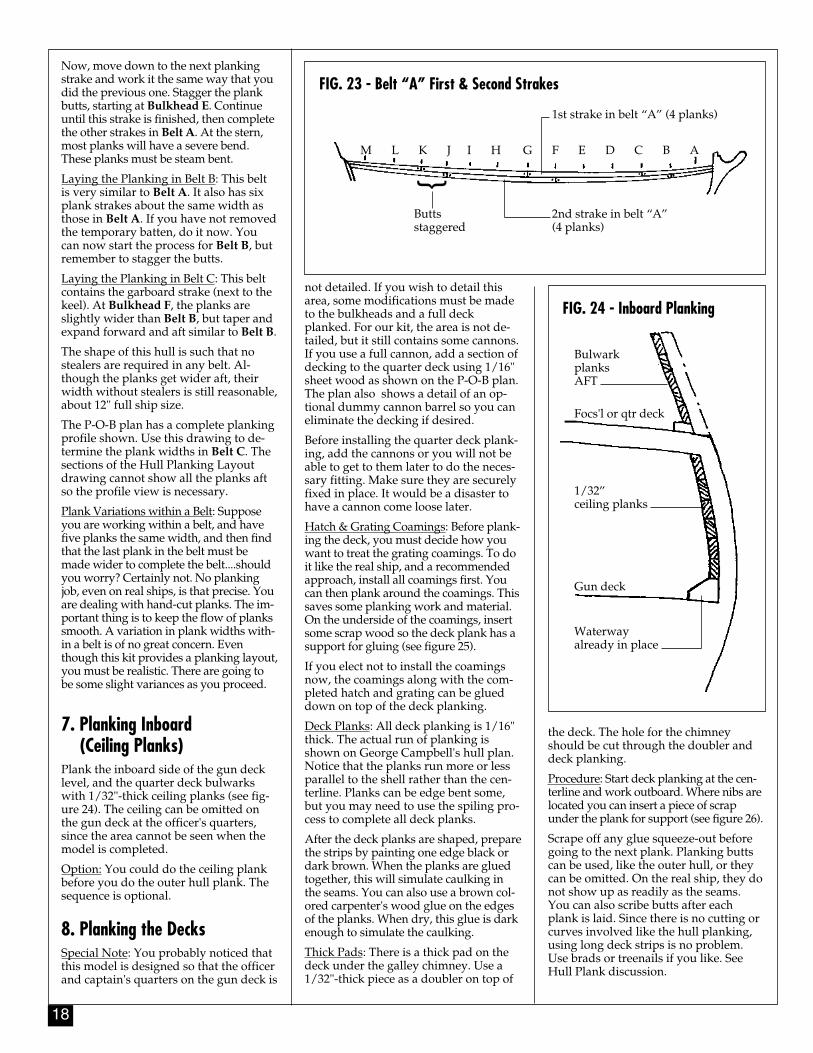
Laying the Planks in Belt A: Each belt ofplanking is done separately. Conse-quently, you can start with any belt. Fordiscussion, let's start at the top and workdown. Belt A has six 1/16"-thick plankstrakes below the wale. The maximumplank width is at Bulkhead G and isroughly 10" real ship width ( about 5/32"model scale). The planks taper forwardto about 3/32". Going aft the planks getwider to about 3/16". Use the 1/16" x3/16" strips for the planking in this belt.
FIG. 20 - Spiling
Use a compass–run the steel point along the plankin place and mark a parallel line on a new plankwith the pencil lead end
Measure width &mark . Draw curve
Cut out plank
Plank already in placeWood–lay along bulkheadswithout edge bending
1
32
17
Use a tick strip and lift the plank widthsfrom the Hull Planking Layout. If youhave changed the locations of the bat-tens, simply divide the space into sixequal plank widths at each bulkhead. Aset of proportional dividers would help.Mark these lines on the bulkheads witha pencil. You should now have a com-pletely marked area for Belt A.
The next step is to cut planks to fit be-tween the marks. Belt A will not requirespiling, so a straight tapered plank can bemade. Start at Bulkhead G. Use fourplanks, one from Bulkhead G to Bulk-head K, another from Bulkhead K to thestern, Bulkhead G to Bulkhead C, andBulkhead C to the stem. First, lay a pieceof planking material over the bulkheadsand mark the length. Mark the plank inpencil at each of the bulkheads. Next, usea set of dividers or a tick strip and lift theplank widths from the marks on the bulk-heads and transfer to the plank. Draw aline through the points and cut the plank.You should now have a tapered plank.Trace this plank to obtain another one forthe other side of the hull.
Install the planks on the hull. Do the sameprocess for the next strake below. Staggerthe butts for this strake. Install a plankfrom Bulkhead F to Bulkhead B, Bulk-head B to the stem, Bulkhead F to Bulk-head J, and Bulkhead J to the stern. Youwill have four planks making up eachstrake from bow to stern (see figure 23).
FIG. 22 - Planking The Counter
FIG. 21 - Belt Battens
Look for smooth flow of battens
Top of wale
BattensM F A
A
BC
A BC
ABC
Counter plank
Miter
Hullplank
Counterplank
1/32” counter plank
Joint
1/16” hull plankSand hull plank tocounter as necessary
18
Now, move down to the next plankingstrake and work it the same way that youdid the previous one. Stagger the plankbutts, starting at Bulkhead E. Continueuntil this strake is finished, then completethe other strakes in Belt A. At the stern,most planks will have a severe bend.These planks must be steam bent.
Laying the Planking in Belt B: This beltis very similar to Belt A. It also has sixplank strakes about the same width asthose in Belt A. If you have not removedthe temporary batten, do it now. Youcan now start the process for Belt B, butremember to stagger the butts.
Laying the Planking in Belt C: This beltcontains the garboard strake (next to thekeel). At Bulkhead F, the planks areslightly wider than Belt B, but taper andexpand forward and aft similar to Belt B.
The shape of this hull is such that nostealers are required in any belt. Al-though the planks get wider aft, theirwidth without stealers is still reasonable,about 12" full ship size.
The P-O-B plan has a complete plankingprofile shown. Use this drawing to de-termine the plank widths in Belt C. Thesections of the Hull Planking Layoutdrawing cannot show all the planks aftso the profile view is necessary.
Plank Variations within a Belt: Supposeyou are working within a belt, and havefive planks the same width, and then findthat the last plank in the belt must bemade wider to complete the belt....shouldyou worry? Certainly not. No plankingjob, even on real ships, is that precise. Youare dealing with hand-cut planks. The im-portant thing is to keep the flow of plankssmooth. A variation in plank widths with-in a belt is of no great concern. Eventhough this kit provides a planking layout,you must be realistic. There are going tobe some slight variances as you proceed.
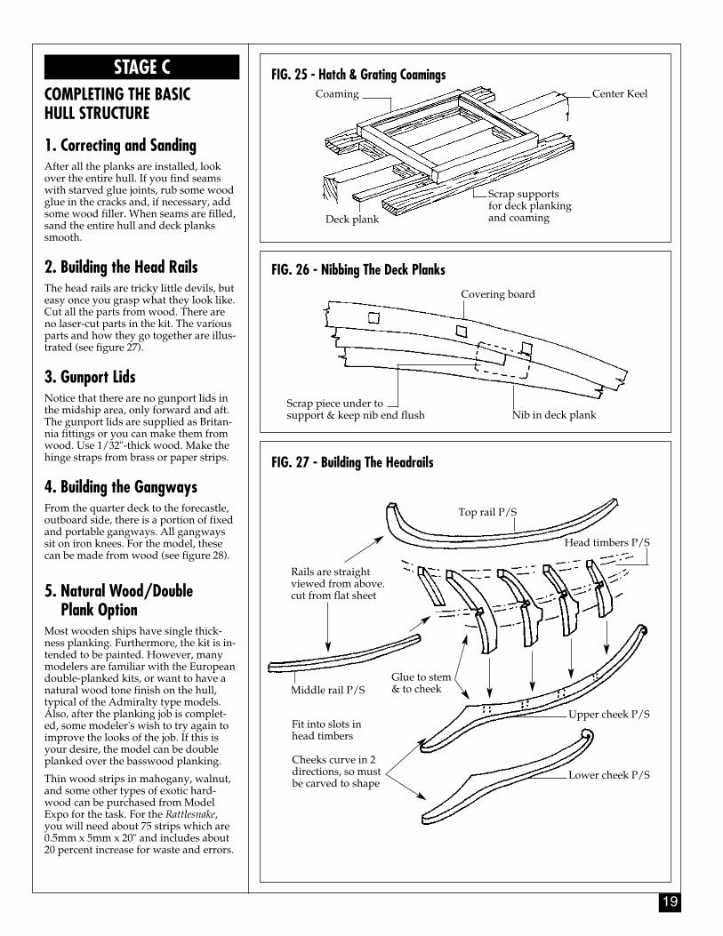
7. Planking Inboard (Ceiling Planks)
Plank the inboard side of the gun decklevel, and the quarter deck bulwarkswith 1/32"-thick ceiling planks (see fig-ure 24). The ceiling can be omitted onthe gun deck at the officer's quarters,since the area cannot be seen when themodel is completed.
Option: You could do the ceiling plankbefore you do the outer hull plank. Thesequence is optional.
8. Planking the DecksSpecial Note: You probably noticed thatthis model is designed so that the officerand captain's quarters on the gun deck is
FIG. 24 - Inboard Plankingnot detailed. If you wish to detail thisarea, some modifications must be madeto the bulkheads and a full deckplanked. For our kit, the area is not de-tailed, but it still contains some cannons.If you use a full cannon, add a section ofdecking to the quarter deck using 1/16"sheet wood as shown on the P-O-B plan.The plan also shows a detail of an op-tional dummy cannon barrel so you caneliminate the decking if desired.
Before installing the quarter deck plank-ing, add the cannons or you will not beable to get to them later to do the neces-sary fitting. Make sure they are securelyfixed in place. It would be a disaster tohave a cannon come loose later.
Hatch & Grating Coamings: Before plank-ing the deck, you must decide how youwant to treat the grating coamings. To doit like the real ship, and a recommendedapproach, install all coamings first. Youcan then plank around the coamings. Thissaves some planking work and material.On the underside of the coamings, insertsome scrap wood so the deck plank has asupport for gluing (see figure 25).
If you elect not to install the coamingsnow, the coamings along with the com-pleted hatch and grating can be glueddown on top of the deck planking.
Deck Planks: All deck planking is 1/16"thick. The actual run of planking isshown on George Campbell's hull plan.Notice that the planks run more or lessparallel to the shell rather than the cen-terline. Planks can be edge bent some,but you may need to use the spiling pro-cess to complete all deck planks.
After the deck planks are shaped, preparethe strips by painting one edge black ordark brown. When the planks are gluedtogether, this will simulate caulking inthe seams. You can also use a brown col-ored carpenter's wood glue on the edgesof the planks. When dry, this glue is darkenough to simulate the caulking.
Thick Pads: There is a thick pad on thedeck under the galley chimney. Use a1/32"-thick piece as a doubler on top of
the deck. The hole for the chimneyshould be cut through the doubler anddeck planking.
Procedure: Start deck planking at the cen-terline and work outboard. Where nibs arelocated you can insert a piece of scrapunder the plank for support (see figure 26).
Scrape off any glue squeeze-out beforegoing to the next plank. Planking buttscan be used, like the outer hull, or theycan be omitted. On the real ship, they donot show up as readily as the seams.You can also scribe butts after eachplank is laid. Since there is no cutting orcurves involved like the hull planking,using long deck strips is no problem.Use brads or treenails if you like. SeeHull Plank discussion.
FIG. 23 - Belt “A” First & Second Strakes
M L K J I H G F E D C B A
Buttsstaggered
1st strake in belt “A” (4 planks)
2nd strake in belt “A” (4 planks)
}BulwarkplanksAFT
Focs'l or qtr deck
1/32” ceiling planks
Gun deck
Waterway already in place
19
FIG. 25 - Hatch & Grating Coamings
FIG. 26 - Nibbing The Deck Planks
Coaming Center Keel
Scrap supportsfor deck plankingand coamingDeck plank
Covering board
Nib in deck plankScrap piece under to support & keep nib end flush
STAGE CCOMPLETING THE BASIC HULL STRUCTURE
1. Correcting and SandingAfter all the planks are installed, lookover the entire hull. If you find seamswith starved glue joints, rub some woodglue in the cracks and, if necessary, addsome wood filler. When seams are filled,sand the entire hull and deck plankssmooth.
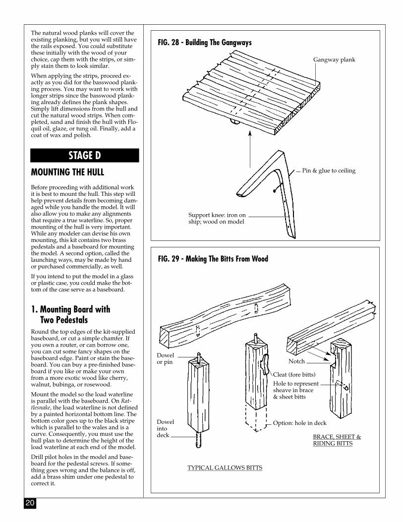
2. Building the Head RailsThe head rails are tricky little devils, buteasy once you grasp what they look like.Cut all the parts from wood. There areno laser-cut parts in the kit. The variousparts and how they go together are illus-trated (see figure 27).
3. Gunport LidsNotice that there are no gunport lids inthe midship area, only forward and aft.The gunport lids are supplied as Britan-nia fittings or you can make them fromwood. Use 1/32"-thick wood. Make thehinge straps from brass or paper strips.
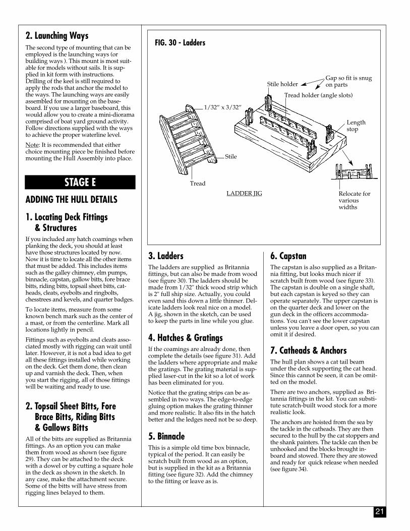
4. Building the GangwaysFrom the quarter deck to the forecastle,outboard side, there is a portion of fixedand portable gangways. All gangwayssit on iron knees. For the model, thesecan be made from wood (see figure 28).
5. Natural Wood/Double Plank Option
Most wooden ships have single thick-ness planking. Furthermore, the kit is in-tended to be painted. However, manymodelers are familiar with the Europeandouble-planked kits, or want to have anatural wood tone finish on the hull,typical of the Admiralty type models.Also, after the planking job is complet-ed, some modeler's wish to try again toimprove the looks of the job. If this isyour desire, the model can be doubleplanked over the basswood planking.
Thin wood strips in mahogany, walnut,and some other types of exotic hard-wood can be purchased from ModelExpo for the task. For the Rattlesnake,you will need about 75 strips which are0.5mm x 5mm x 20" and includes about20 percent increase for waste and errors.
FIG. 27 - Building The Headrails
Top rail P/S
Rails are straightviewed from above.cut from flat sheet
Head timbers P/S
Glue to stem & to cheek
Upper cheek P/S
Lower cheek P/SCheeks curve in 2 directions, so mustbe carved to shape
Middle rail P/S
Fit into slots inhead timbers
20
FIG. 28 - Building The GangwaysThe natural wood planks will cover theexisting planking, but you will still havethe rails exposed. You could substitutethese initially with the wood of yourchoice, cap them with the strips, or sim-ply stain them to look similar.
When applying the strips, proceed ex-actly as you did for the basswood plank-ing process. You may want to work withlonger strips since the basswood plank-ing already defines the plank shapes.Simply lift dimensions from the hull andcut the natural wood strips. When com-pleted, sand and finish the hull with Flo-quil oil, glaze, or tung oil. Finally, add acoat of wax and polish.
STAGE DMOUNTING THE HULLBefore proceeding with additional workit is best to mount the hull. This step willhelp prevent details from becoming dam-aged while you handle the model. It willalso allow you to make any alignmentsthat require a true waterline. So, propermounting of the hull is very important.While any modeler can devise his ownmounting, this kit contains two brasspedestals and a baseboard for mountingthe model. A second option, called thelaunching ways, may be made by handor purchased commercially, as well.
If you intend to put the model in a glassor plastic case, you could make the bot-tom of the case serve as a baseboard.
1. Mounting Board with Two Pedestals
Round the top edges of the kit-suppliedbaseboard, or cut a simple chamfer. Ifyou own a router, or can borrow one,you can cut some fancy shapes on thebaseboard edge. Paint or stain the base-board. You can buy a pre-finished base-board if you like or make your ownfrom a more exotic wood like cherry,walnut, bubinga, or rosewood.
Mount the model so the load waterlineis parallel with the baseboard. On Rat-tlesnake, the load waterline is not definedby a painted horizontal bottom line. Thebottom color goes up to the black stripewhich is parallel to the wales and is acurve. Consequently, you must use thehull plan to determine the height of theload waterline at each end of the model.
Drill pilot holes in the model and base-board for the pedestal screws. If some-thing goes wrong and the balance is off,add a brass shim under one pedestal tocorrect it.
Gangway plank
Pin & glue to ceiling
Support knee: iron onship; wood on model
FIG. 29 - Making The Bitts From Wood
Dowelor pin
Dowelintodeck
Notch
Hole to representsheave in brace & sheet bitts
Option: hole in deck
Cleat (fore bitts)
TYPICAL GALLOWS BITTS
BRACE, SHEET &RIDING BITTS
21
2. Launching WaysThe second type of mounting that can beemployed is the launching ways (orbuilding ways ). This mount is most suit-able for models without sails. It is sup-plied in kit form with instructions.Drilling of the keel is still required toapply the rods that anchor the model tothe ways. The launching ways are easilyassembled for mounting on the base-board. If you use a larger baseboard, thiswould allow you to create a mini-dioramacomprised of boat yard ground activity.Follow directions supplied with the waysto achieve the proper waterline level.
Note: It is recommended that eitherchoice mounting piece be finished beforemounting the Hull Assembly into place.
STAGE EADDING THE HULL DETAILS
1. Locating Deck Fittings & Structures
If you included any hatch coamings whenplanking the deck, you should at leasthave those structures located by now.Now it is time to locate all the other itemsthat must be added. This includes itemssuch as the galley chimney, elm pumps,binnacle, capstan, gallow bitts, fore bracebitts, riding bitts, topsail sheet bitts, cat-heads, cleats, eyebolts and ringbolts,chesstrees and kevels, and quarter badges.
To locate items, measure from someknown bench mark such as the center ofa mast, or from the centerline. Mark alllocations lightly in pencil.
Fittings such as eyebolts and cleats asso-ciated mostly with rigging can wait untillater. However, it is not a bad idea to getall these fittings installed while workingon the deck. Get them done, then cleanup and varnish the deck. Then, whenyou start the rigging, all of those fittingswill be waiting and ready to use.
2. Topsail Sheet Bitts, Fore Brace Bitts, Riding Bitts & Gallows Bitts
All of the bitts are supplied as Britanniafittings. As an option you can makethem from wood as shown (see figure29). They can be attached to the deckwith a dowel or by cutting a square holein the deck as shown in the sketch. Inany case, make the attachment secure.Some of the bitts will have stress fromrigging lines belayed to them.
3. LaddersThe ladders are supplied as Britanniafittings, but can also be made from wood(see figure 30). The ladders should bemade from 1/32" thick wood strip whichis 2" full ship size. Actually, you couldeven sand this down a little thinner. Del-icate ladders look real nice on a model.A jig, shown in the sketch, can be usedto keep the parts in line while you glue.
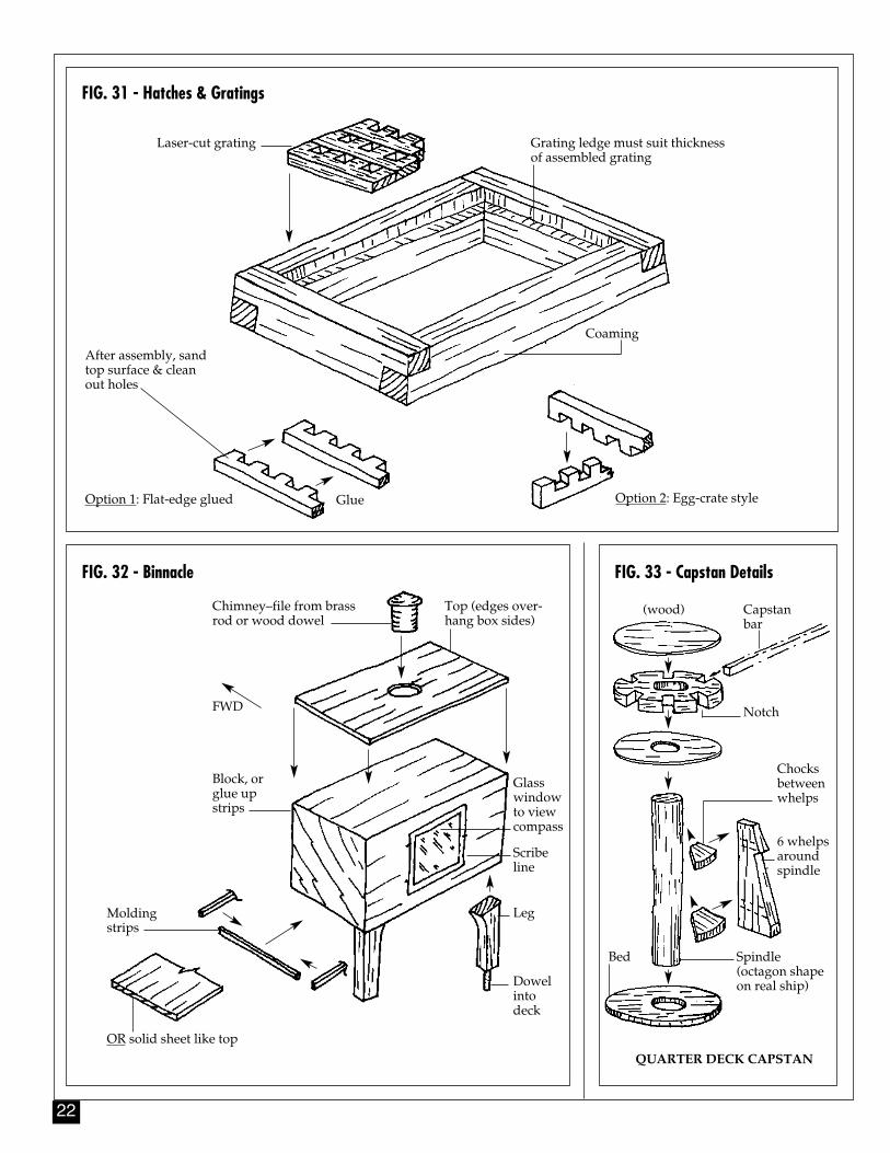
4. Hatches & GratingsIf the coamings are already done, thencomplete the details (see figure 31). Addthe ladders where appropriate and makethe gratings. The grating material is sup-plied laser-cut in the kit so a lot of workhas been eliminated for you.
Notice that the grating strips can be as-sembled in two ways. The edge-to-edgegluing option makes the grating thinnerand more realistic. It also fits in the hatchbetter and the ledges need not be so deep.
5. BinnacleThis is a simple old time box binnacle,typical of the period. It can easily bescratch built from wood as an option,but is supplied in the kit as a Britanniafitting (see figure 32). Add the chimneyto the fitting or leave as is.
FIG. 30 - Ladders
Stile holder
1/32” x 3/32”
Stile
Tread
Tread holder (angle slots)
Gap so fit is snugon parts
Lengthstop
Relocate forvariouswidths
LADDER JIG
6. CapstanThe capstan is also supplied as a Britan-nia fitting, but looks much nicer ifscratch built from wood (see figure 33).The capstan is double on a single shaft,but each capstan is keyed so they canoperate separately. The upper capstan ison the quarter deck and lower on thegun deck in the officers accommoda-tions. You can't see the lower capstanunless you leave a door open, so you canomit it if desired.
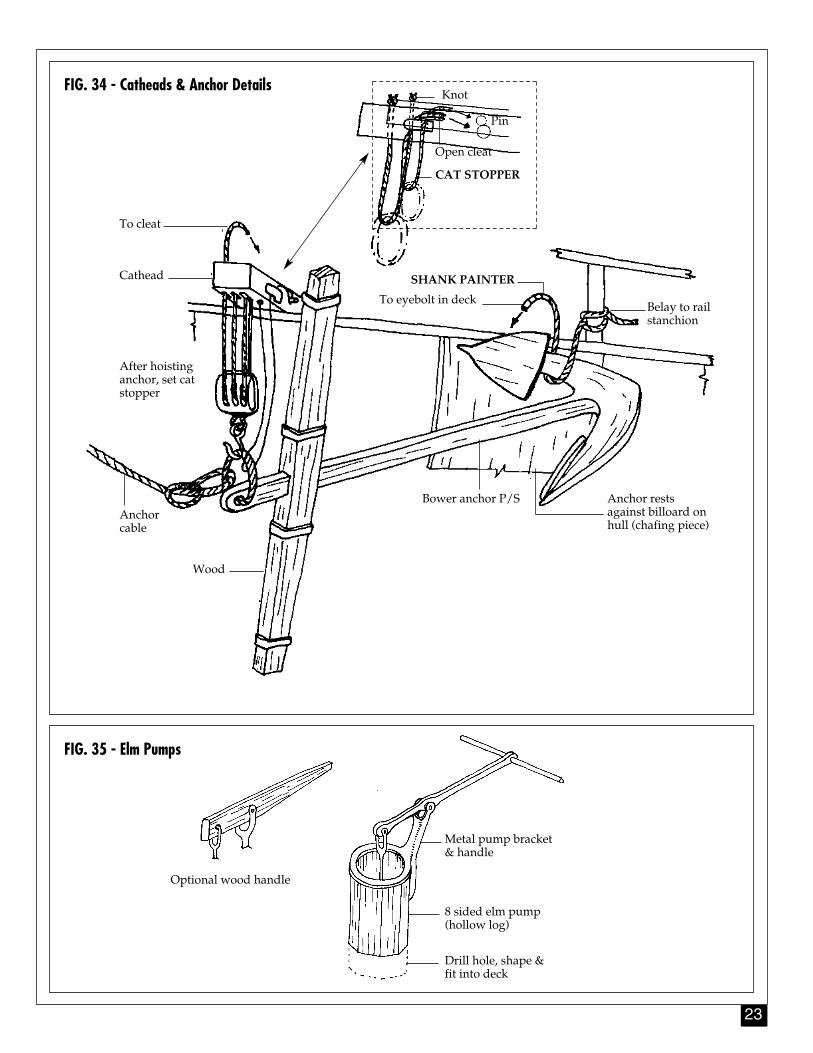
7. Catheads & AnchorsThe hull plan shows a cat tail beamunder the deck supporting the cat head.Since this cannot be seen, it can be omit-ted on the model.
There are two anchors, supplied as Bri-tannia fittings in the kit. You can substi-tute scratch-built wood stock for a morerealistic look.
The anchors are hoisted from the sea bythe tackle in the catheads. They are thensecured to the hull by the cat stoppers andthe shank painters. The tackle can then beunhooked and the blocks brought in-board and stowed. There they are stowedand ready for quick release when needed(see figure 34).
22
FIG. 32 - Binnacle FIG. 33 - Capstan Details
FIG. 31 - Hatches & Gratings
Laser-cut grating Grating ledge must suit thicknessof assembled grating
After assembly, sandtop surface & cleanout holes
Coaming
Option 1: Flat-edge glued Option 2: Egg-crate styleGlue
Chimney–file from brassrod or wood dowel
FWD
Top (edges over-hang box sides)
Block, orglue upstrips
Scribeline
Glasswindowto viewcompass
Leg
Dowelintodeck
Moldingstrips
OR solid sheet like top
Capstanbar
Notch
6 whelpsaroundspindle
Chocks betweenwhelps
Spindle(octagon shapeon real ship)
Bed
QUARTER DECK CAPSTAN
(wood)
23
FIG. 34 - Catheads & Anchor Details
FIG. 35 - Elm Pumps
To eyebolt in deck
SHANK PAINTER
Belay to railstanchion
To cleat
Cathead
After hoisting anchor, set cat stopper
Anchorcable
Wood
Bower anchor P/S Anchor restsagainst billoard onhull (chafing piece)
Optional wood handle
Metal pump bracket& handle
8 sided elm pump (hollow log)
Drill hole, shape &fit into deck
Knot
Pin
Open cleat
CAT STOPPER
24
8. Elm PumpsThe pumps are supplied as Britannia fit-tings (see figure 35). Drill holes in thedeck and insert the pump fitting. Thepump body is a hollowed-out log. Theplans show a metal bracket and pumphandle. However, on some early ships,the pump handle was a simple woodhandle, an option shown in the sketch.
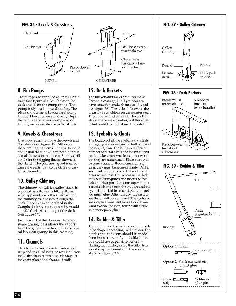
9. Kevels & ChesstreesUse wood strips to make the kevels andchesstrees (see figure 36). Althoughthese are rigging items, it is best to makeand install them now. You need not putactual sheaves in the pieces. Simply drilla hole for the rigging line as shown inthe sketch. The pins are a good idea be-cause the parts may come off if not fas-tened securely.
10. Galley ChimneyThe chimney, or call it a galley stack, issupplied as a Britannia fitting. It haswhat apparently is a thick pad aroundthe chimney as it passes through thedeck. Since this is not defined in theCampbell plans, it is suggested you adda 1/32"-thick piece on top of the deck(see figure 37).
Just forward of the chimney there is asteam grating. This allows the vaporsfrom the galley stove to vent. Use a typi-cal laser-cut grating in this coaming.
11. ChannelsThe channels can be made from woodstrip and installed now, or wait until youmake the chain plates. Consult Stage Hfor chain plates and channel details.
FIG. 37 - Galley Chimney
12. Deck BucketsThe buckets and racks are supplied asBritannia castings, but if you want tohave some fun, make them out of wood(see figure 38). The racks fit between thebreast rail stanchions on the quarter deck.There are six buckets in all. The bucketsshould have rope handles, but this smalldetail could be omitted on the model.
13. Eyebolts & CleatsThe location of all the eyebolts and cleatsfor rigging are shown on the hull plan andthe rigging plan. The kit has a sufficientnumber of metal cleats and eyebolts. Youcould make your own cleats out of woodbut they are rather small. Since there willbe some strain on these items from rig-ging, they must be secured firmly. Drill asmall hole through each cleat and insert abrass wire or pin. Drill a hole in the deckor wherever required and insert the eye-bolt and cleat pin. Use some super glue ona toothpick and touch the glue around theeyebolt and cleat to secure it. Careful, nottoo much glue. After it is dry, tug on it tosee that it will not come out. The eyeboltsare simply a wire bent into a loop. If youwant to close the loop, touch with a littlesolder or epoxy glue.
14. Rudder & TillerThe rudder is a laser-cut piece but needsto be shaped according to the plans. Thepintles and gudgeons should be madefrom brass strip, or if you dislike brassyou could use paper strip. After in-stalling the rudder, make the tiller fromwood strip and insert it in the rudderstock (see figure 39).
FIG. 38 - Deck Buckets
FIG. 39 - Rudder & Tiller
FIG. 36 - Kevels & Chesstrees
Cleat end
Line belays
Pin or dowel to hull
Line
Drill hole to rep-resent sheave
Chesstree is basically a fair-lead for line
CHESSTREEKEVEL
Galleychimney
Round Square
Thick padon deck
Fit intodeck
Breast rail atforecastle deck
Rack betweenbreast rail stanchions
6 wooden buckets (rope handle)
Tiller
Rudder
Solder or glue
Pintle & gudgeon
Option 2: Pin & cut head off , or just glue
Solder orglue pin
Brassstrip
Option 1: no pin
25
15. Quarter BadgesA separate Britannia fitting is supplied forthe port and starboard quarter badges.Drill a hole at the top and bottom of eachquarter badge so you can insert a pin formounting and gluing them to the hull. Fita piece of acetate in the window and paintthe back either pale blue for a reflectivewindow or black to fake a window area.There is no actual hole in the hull wherethe window goes. The interior is not de-tailed in this area anyway and the castingfits directly on a flat surface.
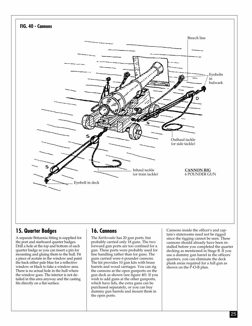
16. Cannons The Rattlesnake has 20 gun ports, butprobably carried only 18 guns. The twoforward gun ports are too confined for agun. These ports were probably used forline handling rather than for guns. Theguns carried were 6 pounder cannons.The kit provides 10 gun kits with brassbarrels and wood carriages. You can rigthe cannons at the open gunports on thegun deck as shown (see figure 40). If youwish to add guns at the other gunports,which have lids, the extra guns can bepurchased separately, or you can buydummy gun barrels and mount them inthe open ports.
Cannons inside the officer's and cap-tain's staterooms need not be riggedsince the rigging cannot be seen. Thesecannons should already have been in-stalled before you completed the quarterdecking as mentioned in Stage B. If youuse a dummy gun barrel in the officers'quarters, you can eliminate the deckplank areas required for a full gun asshown on the P-O-B plan.
FIG. 40 - Cannons
Breech line
Eyeboltsin bulwark
Eyebolt in deck
Inhaul tackle (or train tackle)
Outhaul tackle (or side tackle)
CANNON RIG6 POUNDER GUN
26
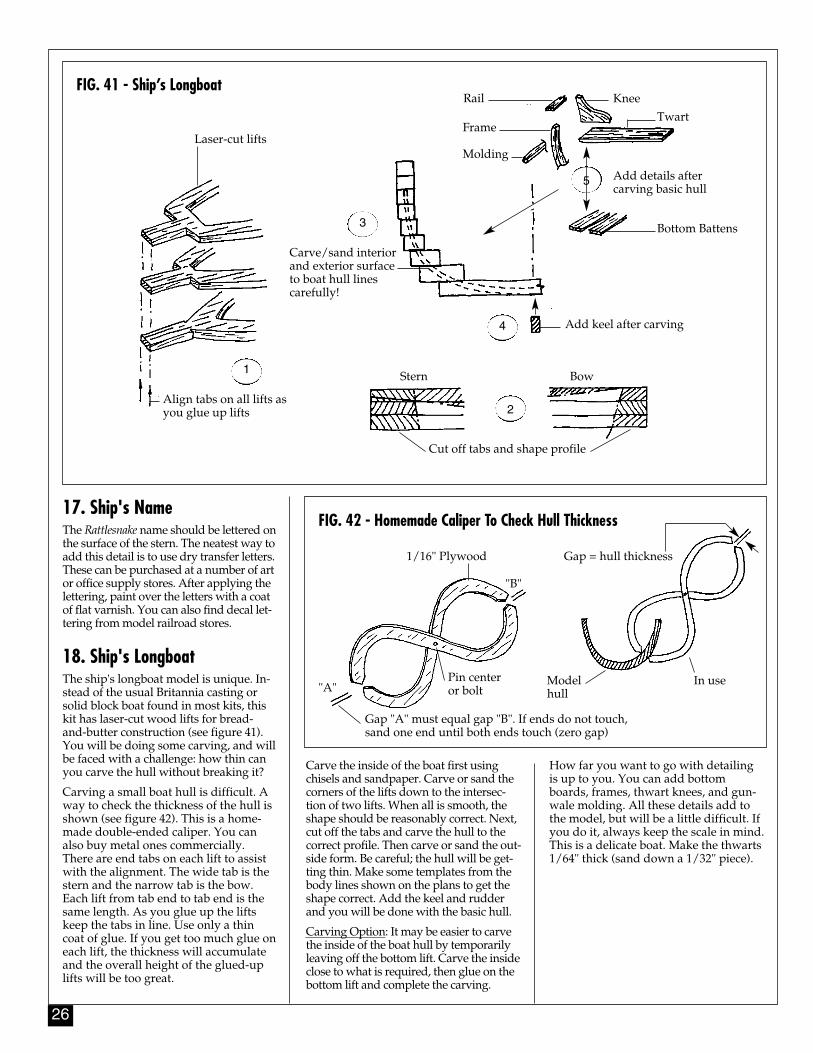
17. Ship's NameThe Rattlesnake name should be lettered onthe surface of the stern. The neatest way toadd this detail is to use dry transfer letters.These can be purchased at a number of artor office supply stores. After applying thelettering, paint over the letters with a coatof flat varnish. You can also find decal let-tering from model railroad stores.
18. Ship's LongboatThe ship's longboat model is unique. In-stead of the usual Britannia casting orsolid block boat found in most kits, thiskit has laser-cut wood lifts for bread-and-butter construction (see figure 41).You will be doing some carving, and willbe faced with a challenge: how thin canyou carve the hull without breaking it?
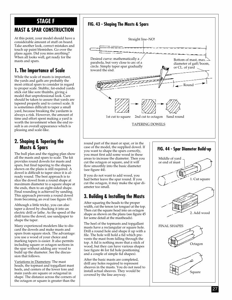
Carving a small boat hull is difficult. Away to check the thickness of the hull isshown (see figure 42). This is a home-made double-ended caliper. You canalso buy metal ones commercially. There are end tabs on each lift to assistwith the alignment. The wide tab is thestern and the narrow tab is the bow.Each lift from tab end to tab end is thesame length. As you glue up the liftskeep the tabs in line. Use only a thincoat of glue. If you get too much glue oneach lift, the thickness will accumulateand the overall height of the glued-uplifts will be too great.
FIG. 42 - Homemade Caliper To Check Hull Thickness
Carve the inside of the boat first usingchisels and sandpaper. Carve or sand thecorners of the lifts down to the intersec-tion of two lifts. When all is smooth, theshape should be reasonably correct. Next,cut off the tabs and carve the hull to thecorrect profile. Then carve or sand the out-side form. Be careful; the hull will be get-ting thin. Make some templates from thebody lines shown on the plans to get theshape correct. Add the keel and rudderand you will be done with the basic hull.
Carving Option: It may be easier to carvethe inside of the boat hull by temporarilyleaving off the bottom lift. Carve the insideclose to what is required, then glue on thebottom lift and complete the carving.
How far you want to go with detailingis up to you. You can add bottomboards, frames, thwart knees, and gun-wale molding. All these details add tothe model, but will be a little difficult. Ifyou do it, always keep the scale in mind.This is a delicate boat. Make the thwarts1/64" thick (sand down a 1/32" piece).
FIG. 41 - Ship’s Longboat
Laser-cut lifts
Rail Knee
Frame
Molding
Twart
1
2
3
4
5 Add details aftercarving basic hull
Bottom Battens
Add keel after carving
Stern Bow
Cut off tabs and shape profile
Align tabs on all lifts asyou glue up lifts
Carve/sand interiorand exterior surfaceto boat hull linescarefully!
1/16" Plywood Gap = hull thickness
In useModelhull
Pin centeror bolt
Gap "A" must equal gap "B". If ends do not touch,sand one end until both ends touch (zero gap)
"B"
"A"
27
STAGE FMAST & SPAR CONSTRUCTIONAt this point, your model should have aconsiderable amount of stuff on board.Take another look, correct mistakes andtouch up paint blemishes. Go over theplans again. Did you miss anything?When all looks well, get ready for themasts and spars.
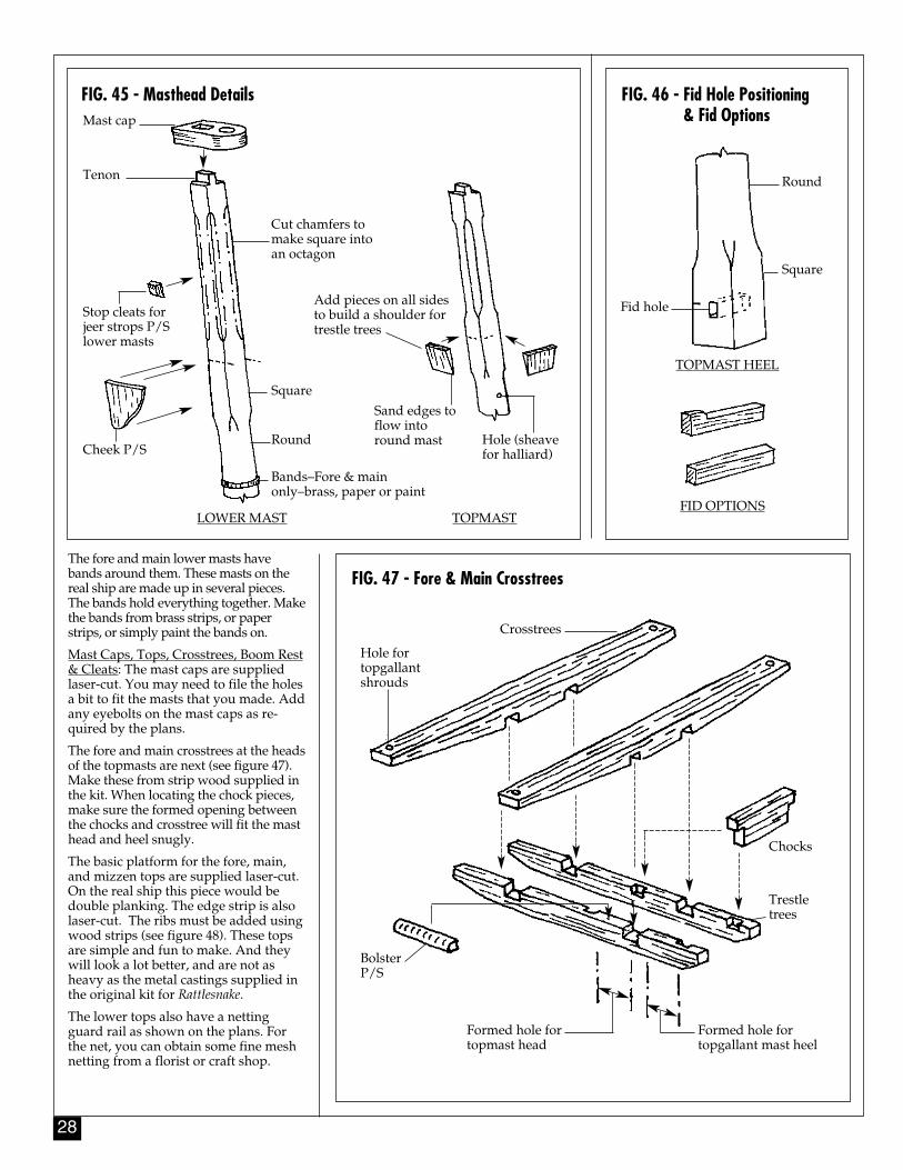
1. The Importance of ScaleWhile the scale of masts is important,the yards and gaffs are probably themost critical spars to consider in regardto proper scale. Stubby, fat-ended yardsstick out like sore thumbs, giving amodel that unprofessional look. Careshould be taken to assure that yards aretapered properly and to correct scale. Itis sometimes difficult to taper a smallyard, because breaking the yardarm isalways a risk. However, the amount oftime and effort spent making a yard isworth the investment when the end re-sult is an overall appearance which ispleasing and scale-like.
2. Shaping & Tapering the Masts & Spars
The hull plan and the rigging plan showall the masts and spars to scale. The kitprovides round dowels for masts andspars, but final tapering to the shapesshown on the plans is still required. Adowel is difficult to taper since it is al-ready round. The best approach is toslice the dowel from a round shape atmaximum diameter to a square shape atthe ends, then to an eight-sided shape.Final rounding is achieved by sanding.This approach prevents a round dowelfrom becoming an oval (see figure 43).
Although a little tricky, you can alsotaper a dowel by chucking it into anelectric drill or lathe. As the speed of thedrill turns the dowel, use sandpaper toshape the taper.
Many experienced modelers like to dis-card the dowels and make masts andspars from square stock. The advantage:you use a wood of your choice andmarking tapers is easier. It also permitsincluding square or octagon sections inthe spar without adding any wood tobuild up the diameter. See the discus-sion that follows.
Variations in Diameters: The mastheads, the topmast and topgallant mastheels, and centers of the lower fore andmain yards are square or octagonal inshape. The distance across the corners ofthe octagon or square is greater than the
FIG. 44 - Spar Diameter Build-upround part of the mast or spar, or in thecase of the model, the supplied dowel. Ifyou want to shape the spars correctly,you must first add some wood in theseareas to increase the diameter. Then youcut the octagon or square, and it willflow smoothly into the basic diameter(see figure 44).
If you do not want to add wood, youhad better leave the spar round. If youcut the octagon, it may make the spar di-ameter too small.
3. Building & Installing the MastsAfter squaring the heads to the properwidth, cut the tenon (or tongue) at the top.Then cut the square head into an octagonshape as shown on the plans (see figure 45for some detail at the mastheads).
The heel of the topmasts and topgallantmasts have a rectangular or square hole.Drill a round hole and shape it up with afile. The hole will hold a fid which pre-vents the mast from falling through thetop. A fid is nothing more that a stick ofwood, but they can have various shapes(see figure 46 for fid hole positioningand a couple of simple fid shapes).
After the basic masts are completed,drill any holes required to representsheaves in the masts. You do not need toinstall actual sheaves. They would becovered by the line anyway.
FIG. 43 - Shaping The Masts & Spars
Straight line–NO!
Desired curve: mathematically aparabola, but very close to arc of acircle. Simply taper spar graduallytoward the end.
Bottom of mast, max.diameter of gaff/boom,or CL. of yard
Round
TAPERING DOWELS
1st cut to square 2nd cut to octagon Sand round
Middle of yard or end of mast
1. Cut square
2. Add wood
FINAL SHAPES
Octagon
Square
28
FIG. 46 - Fid Hole Positioning & Fid Options
The fore and main lower masts havebands around them. These masts on thereal ship are made up in several pieces.The bands hold everything together. Makethe bands from brass strips, or paperstrips, or simply paint the bands on.
Mast Caps, Tops, Crosstrees, Boom Rest& Cleats: The mast caps are suppliedlaser-cut. You may need to file the holesa bit to fit the masts that you made. Addany eyebolts on the mast caps as re-quired by the plans.
The fore and main crosstrees at the headsof the topmasts are next (see figure 47).Make these from strip wood supplied inthe kit. When locating the chock pieces,make sure the formed opening betweenthe chocks and crosstree will fit the masthead and heel snugly.
The basic platform for the fore, main,and mizzen tops are supplied laser-cut.On the real ship this piece would bedouble planking. The edge strip is alsolaser-cut. The ribs must be added usingwood strips (see figure 48). These topsare simple and fun to make. And theywill look a lot better, and are not asheavy as the metal castings supplied inthe original kit for Rattlesnake.
The lower tops also have a nettingguard rail as shown on the plans. Forthe net, you can obtain some fine meshnetting from a florist or craft shop.
FIG. 45 - Masthead Details
FIG. 47 - Fore & Main Crosstrees
Mast cap
Tenon
Stop cleats forjeer strops P/Slower masts
Cheek P/S
Cut chamfers tomake square intoan octagon
Square
Round
Bands–Fore & mainonly–brass, paper or paint
Sand edges toflow intoround mast
Add pieces on all sidesto build a shoulder fortrestle trees
Hole (sheavefor halliard)
LOWER MAST TOPMAST
Round
Square
Fid hole
FID OPTIONS
TOPMAST HEEL
Crosstrees
Hole fortopgallantshrouds
BolsterP/S
Formed hole fortopmast head
Formed hole for topgallant mast heel
Chocks
Trestletrees
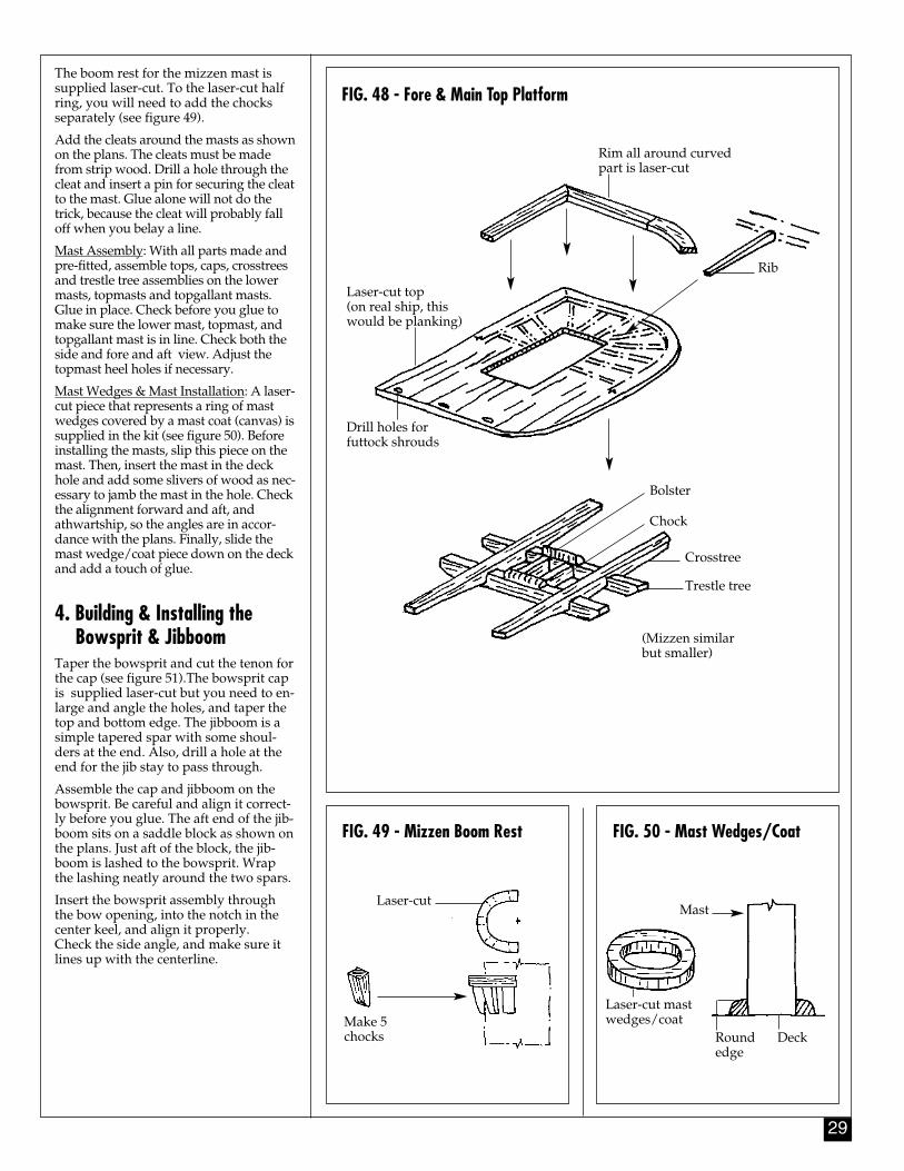
29
The boom rest for the mizzen mast issupplied laser-cut. To the laser-cut halfring, you will need to add the chocksseparately (see figure 49).
Add the cleats around the masts as shownon the plans. The cleats must be madefrom strip wood. Drill a hole through thecleat and insert a pin for securing the cleatto the mast. Glue alone will not do thetrick, because the cleat will probably falloff when you belay a line.
Mast Assembly: With all parts made andpre-fitted, assemble tops, caps, crosstreesand trestle tree assemblies on the lowermasts, topmasts and topgallant masts.Glue in place. Check before you glue tomake sure the lower mast, topmast, andtopgallant mast is in line. Check both theside and fore and aft view. Adjust thetopmast heel holes if necessary.
Mast Wedges & Mast Installation: A laser-cut piece that represents a ring of mastwedges covered by a mast coat (canvas) issupplied in the kit (see figure 50). Beforeinstalling the masts, slip this piece on themast. Then, insert the mast in the deckhole and add some slivers of wood as nec-essary to jamb the mast in the hole. Checkthe alignment forward and aft, andathwartship, so the angles are in accor-dance with the plans. Finally, slide themast wedge/coat piece down on the deckand add a touch of glue.
4. Building & Installing the Bowsprit & Jibboom
Taper the bowsprit and cut the tenon forthe cap (see figure 51).The bowsprit capis supplied laser-cut but you need to en-large and angle the holes, and taper thetop and bottom edge. The jibboom is asimple tapered spar with some shoul-ders at the end. Also, drill a hole at theend for the jib stay to pass through.
Assemble the cap and jibboom on thebowsprit. Be careful and align it correct-ly before you glue. The aft end of the jib-boom sits on a saddle block as shown onthe plans. Just aft of the block, the jib-boom is lashed to the bowsprit. Wrapthe lashing neatly around the two spars.
Insert the bowsprit assembly throughthe bow opening, into the notch in thecenter keel, and align it properly. Check the side angle, and make sure itlines up with the centerline.
FIG. 49 - Mizzen Boom Rest FIG. 50 - Mast Wedges/Coat
FIG. 48 - Fore & Main Top Platform
Rim all around curvedpart is laser-cut
Rib
Laser-cut top (on real ship, thiswould be planking)
Drill holes forfuttock shrouds
Bolster
Chock
Crosstree
Trestle tree
(Mizzen similarbut smaller)
Laser-cut
Make 5chocks
Mast
Roundedge
Deck
Laser-cut mastwedges/coat
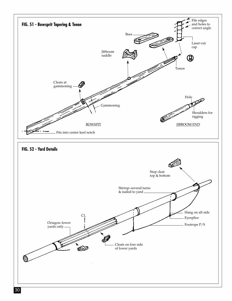
30
FIG. 51 - Bowsprit Tapering & Tenon
FIG. 52 - Yard Details
Bees
Jibboomsaddle
Tenon
Hole
JIBBOOM END
Shoulders forrigging
Gammoning
BOWSPIT
Cleats atgammoning
Fits into center keel notch
Stop cleattop & bottom
Stirrup–several turns& nailed to yard
Hang on aft side
Eyesplice
Footrope P/S
Cleats on fore sideof lower yards
Octagon–loweryards only
CL
File edgesand holes tocorrect angle
Laser-cutcap
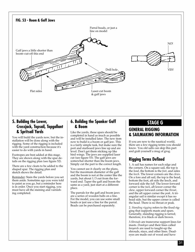
31
5. Building the Lower, Crossjack, Topsail, Topgallant& Spritsail Yards
You will build the yards now, but the in-stallation will be done along with therigging. Some of the rigging is includedwith the yard construction because it'seasier to do with yards in hand.
Footropes are best added at this stage.They are shown along with the spar de-tails on the rigging plan (see figure 52).
There are a few cleats to be added to theshaped spar. The rigging plan andsketch shows the detail.
Reminder: Stain the yards before you setthem aside. Sometime ago you were toldto paint as you go, but a reminder hereis in order. Once you start rigging, youmust have all the staining and varnish-ing completed.
STAGE GGENERAL RIGGING & SAILMAKING INFORMATIONIf you are new to the nautical world,there are a few rigging terms you shouldknow. You old salts can skip this partand grab yourself a mug of grog.
Rigging Terms Defined1. A sail has names for each edge andthe corners. On a square sail, the top isthe head, the bottom is the foot, and sidesthe leech. The lower corners are the clews.On a fore and aft sail, the top is the head,bottom the foot, aft side the leech, andforward side the luff. The lower forwardcorner is the tack, aft lower corner theclew, upper forward corner the throat,and the aft upper corner the peak. A tri-angular sail is similar except it has nohead side, but the upper corner is calledthe head. There is no throat or peak.
2. Standing rigging refers to the fixed rig-ging that supports masts and spars.Generally, standing rigging is tarred;therefore, it is black or dark brown.
3.Shrouds are transverse support lines formasts. Deadeyes and their lines calledlanyards are used to taught-up theshrouds, stays, and other lines. Dead-eyes are made out of wood and have
6. Building the Spanker Gaff & Boom
Like the yards, these spars should becompleted in hand as much as possibleand will be installed later. The new itemnow to build is a boom or gaff jaw. Thisis a fairly simple task, but make sure theport and starboard jaws line up and arelevel. Don't get them sticking up likebird wings. The jaws are supplied lasercut (see figure 53). The gaff jaws aresomewhat shorter than the boom jaws.Simply cut the part to the correct length.
You cannot see it clearly on the plans,but the maximum diameter of the gaffand the boom is not at the center like theyards, but about 1/3 out from the for-ward end. Taper the gaff and boom thesame as a yard, just start at a differentplace.
The parrals for the gaff and boom jawsare a series of wooden balls on a line.For the model, you can use some smallbeads or just use a line for the parral.Beads can be purchased separately.
FIG. 53 - Boom & Gaff Jaws
Gaff jaws a little shorter thanboom–cut-off this end
Parral beads, or just aline on model
NO!
YES!
Laser-cut boom& gaff jaws
Flat sides
Drill hole
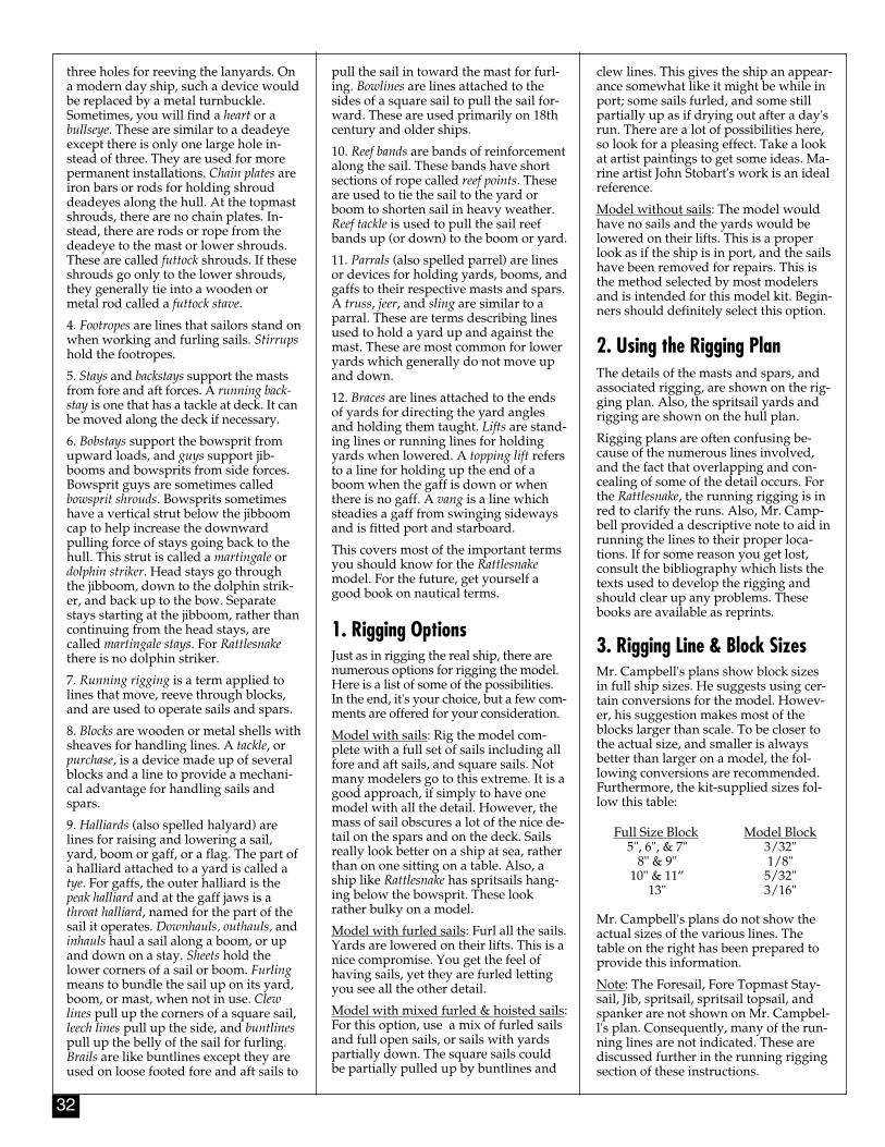
32
three holes for reeving the lanyards. Ona modern day ship, such a device wouldbe replaced by a metal turnbuckle.Sometimes, you will find a heart or abullseye. These are similar to a deadeyeexcept there is only one large hole in-stead of three. They are used for morepermanent installations. Chain plates areiron bars or rods for holding shrouddeadeyes along the hull. At the topmastshrouds, there are no chain plates. In-stead, there are rods or rope from thedeadeye to the mast or lower shrouds.These are called futtock shrouds. If theseshrouds go only to the lower shrouds,they generally tie into a wooden ormetal rod called a futtock stave.
4. Footropes are lines that sailors stand onwhen working and furling sails. Stirrupshold the footropes.
5. Stays and backstays support the mastsfrom fore and aft forces. A running back-stay is one that has a tackle at deck. It canbe moved along the deck if necessary.
6. Bobstays support the bowsprit fromupward loads, and guys support jib-booms and bowsprits from side forces.Bowsprit guys are sometimes calledbowsprit shrouds. Bowsprits sometimeshave a vertical strut below the jibboomcap to help increase the downwardpulling force of stays going back to thehull. This strut is called a martingale ordolphin striker. Head stays go throughthe jibboom, down to the dolphin strik-er, and back up to the bow. Separatestays starting at the jibboom, rather thancontinuing from the head stays, arecalled martingale stays. For Rattlesnakethere is no dolphin striker.
7. Running rigging is a term applied tolines that move, reeve through blocks,and are used to operate sails and spars.
8. Blocks are wooden or metal shells withsheaves for handling lines. A tackle, orpurchase, is a device made up of severalblocks and a line to provide a mechani-cal advantage for handling sails andspars.
9. Halliards (also spelled halyard) arelines for raising and lowering a sail,yard, boom or gaff, or a flag. The part ofa halliard attached to a yard is called atye. For gaffs, the outer halliard is thepeak halliard and at the gaff jaws is athroat halliard, named for the part of thesail it operates. Downhauls, outhauls, andinhauls haul a sail along a boom, or upand down on a stay. Sheets hold thelower corners of a sail or boom. Furlingmeans to bundle the sail up on its yard,boom, or mast, when not in use. Clewlines pull up the corners of a square sail,leech lines pull up the side, and buntlinespull up the belly of the sail for furling.Brails are like buntlines except they areused on loose footed fore and aft sails to
pull the sail in toward the mast for furl-ing. Bowlines are lines attached to thesides of a square sail to pull the sail for-ward. These are used primarily on 18thcentury and older ships.
10. Reef bands are bands of reinforcementalong the sail. These bands have shortsections of rope called reef points. Theseare used to tie the sail to the yard orboom to shorten sail in heavy weather.Reef tackle is used to pull the sail reefbands up (or down) to the boom or yard.
11. Parrals (also spelled parrel) are linesor devices for holding yards, booms, andgaffs to their respective masts and spars.A truss, jeer, and sling are similar to aparral. These are terms describing linesused to hold a yard up and against themast. These are most common for loweryards which generally do not move upand down.
12. Braces are lines attached to the endsof yards for directing the yard anglesand holding them taught. Lifts are stand-ing lines or running lines for holdingyards when lowered. A topping lift refersto a line for holding up the end of aboom when the gaff is down or whenthere is no gaff. A vang is a line whichsteadies a gaff from swinging sidewaysand is fitted port and starboard.
This covers most of the important termsyou should know for the Rattlesnakemodel. For the future, get yourself agood book on nautical terms.
1. Rigging OptionsJust as in rigging the real ship, there arenumerous options for rigging the model.Here is a list of some of the possibilities.In the end, it's your choice, but a few com-ments are offered for your consideration.
Model with sails: Rig the model com-plete with a full set of sails including allfore and aft sails, and square sails. Notmany modelers go to this extreme. It is agood approach, if simply to have onemodel with all the detail. However, themass of sail obscures a lot of the nice de-tail on the spars and on the deck. Sailsreally look better on a ship at sea, ratherthan on one sitting on a table. Also, aship like Rattlesnake has spritsails hang-ing below the bowsprit. These lookrather bulky on a model.
Model with furled sails: Furl all the sails.Yards are lowered on their lifts. This is anice compromise. You get the feel ofhaving sails, yet they are furled lettingyou see all the other detail.
Model with mixed furled & hoisted sails:For this option, use a mix of furled sailsand full open sails, or sails with yardspartially down. The square sails couldbe partially pulled up by buntlines and
clew lines. This gives the ship an appear-ance somewhat like it might be while inport; some sails furled, and some stillpartially up as if drying out after a day'srun. There are a lot of possibilities here,so look for a pleasing effect. Take a lookat artist paintings to get some ideas. Ma-rine artist John Stobart's work is an idealreference.
Model without sails: The model wouldhave no sails and the yards would belowered on their lifts. This is a properlook as if the ship is in port, and the sailshave been removed for repairs. This isthe method selected by most modelersand is intended for this model kit. Begin-ners should definitely select this option.
2. Using the Rigging PlanThe details of the masts and spars, andassociated rigging, are shown on the rig-ging plan. Also, the spritsail yards andrigging are shown on the hull plan.
Rigging plans are often confusing be-cause of the numerous lines involved,and the fact that overlapping and con-cealing of some of the detail occurs. Forthe Rattlesnake, the running rigging is inred to clarify the runs. Also, Mr. Camp-bell provided a descriptive note to aid inrunning the lines to their proper loca-tions. If for some reason you get lost,consult the bibliography which lists thetexts used to develop the rigging andshould clear up any problems. Thesebooks are available as reprints.
3. Rigging Line & Block SizesMr. Campbell's plans show block sizesin full ship sizes. He suggests using cer-tain conversions for the model. Howev-er, his suggestion makes most of theblocks larger than scale. To be closer tothe actual size, and smaller is alwaysbetter than larger on a model, the fol-lowing conversions are recommended.Furthermore, the kit-supplied sizes fol-low this table:
Full Size Block Model Block5", 6", & 7" 3/32"
8" & 9" 1/8"10" & 11” 5/32"
13" 3/16"
Mr. Campbell's plans do not show theactual sizes of the various lines. Thetable on the right has been prepared toprovide this information.
Note: The Foresail, Fore Topmast Stay-sail, Jib, spritsail, spritsail topsail, andspanker are not shown on Mr. Campbel-l's plan. Consequently, many of the run-ning lines are not indicated. These arediscussed further in the running riggingsection of these instructions.

33
The diameter of lanyards for deadeyesand hearts can be about 1/3 the diame-ter of the line, such as a shroud.
The rigging lines provided in the kit donot cover all the sizes shown in the table.There are only certain sizes available.The guide immediately following thetable suggests line selections.
It is important to use as many line sizes asyou have available. The relative differencein the various lines adds tremendously tothe visual effect. With many variances, themodel looks more scale-like.
4. Treating the LinesWorming, Parcelling & Serving: Lineson ships were wormed, parcelled andserved (a method of protecting parts of arope) where they are likely to be chafed,such as the shrouds. For models, worm-ing (laying thin pieces of line (theworms) between the strands), and par-celling (winding strips of canvas saturat-ed with tar over the part wormed) is un-necessary. Only serving (tightly bindingthe wormed and parcelled area in theother direction with spun yarn) shouldbe considered. Serving the lines shouldbe done with fine silk or linen thread.Avoid fuzzy cotton, if possible.
For this model, because of the smallsizes, serving is not recommended. Justuse the line as-is and coat it heavily withbeeswax.
Seizings: Use cotton, nylon, or silksewing thread to seize the lines. After se-curing each line, touch the seizing withthin super glue or diluted white glue(see figure 54 for some seizing methods).
Beeswax: Beeswax protects the linesagainst moisture and helps to eliminatefuzz. If the beeswax is hard, hold it up toa light bulb to soften it. Run the lineacross the beeswax block. Then run itthrough your fingers to soften it andsmooth it out. Do this several times soyou get a good coat of wax on the line.
5. Belaying Pins & Their LinesThe various notes on the plan tell youwhere to belay the lines. On Rattlesnake, alot of lines are belayed to cleats or tied tothe various rails. There are not as manybelaying pins as you would find on a 19th-century ship. If you install sails and thelines are not shown on the plans, use yourown judgement and belay the lines at con-venient points. Consult the texts listed inthe bibliography for more detail on belay-ing points. All belaying points shouldhave a coil of rope (see figure 55).
Rigging Line Ship Size Name Diameter
Standing Rigging:Fore & Main Shrouds 2-1/4"Fore & Main Ratlines 1/2"Fore & Main Topmast Shrouds 1-1/2"Fore & Main Topmast Ratlines 3/8"Fore & Main Topgallant Shrouds 3/4"Fore & Main Topmast Backstays 1-1/2"Fore & Main Topgallant Backstay 3/4"Mizzen Shrouds 1-1/2"Mizzen Ratlines 3/8"Mizzen Topmast Shrouds 3/4"Mizzen Topmast Ratlines 3/8"Mizzen Topmast Backstays 3/4"Fore Topgallant Stay 1"Jibstay 1-5/8"Fore Topmast Stay 1-5/8"Fore Topmast Preventer Stay 1-1/4"Forestay 3"Main Topgallant Stay 1"Main Topmast Stay 1-3/4"Main Stay 3-1/4"Mizzen Topmast Stay 1"Mizzen Stay 1-3/4"Bobstay (doubled) 1-5/8"Bowsprit Shrouds 1-1/2"Jibboom Guy Pendants 3/4"Lower Yard Footropes 1-1/8"Topsail Yard Footropes 1"Topgallant Yard Footropes 5/8"Spritsail 3/4"Spritsail Topsail Yard Footropes 3/4"Jibboom Footropes 1"Spanker Boom Footropes 3/4"
Running Rigging:Fore & Main Sheets 1-1/4"Fore & Main Tacks 1-5/8"Fore & Main Clew Garnets 3/4"Fore & Main Buntlines 5/8"Fore & Main Leech lines 5/8"Fore & Main Bowlines 1"Fore & Main Lifts 1"Fore & Main Brace Pendants 1-1/8"Fore & Main Braces 3/4"Fore & Main Truss Pendants 1-1/2"Fore & Main Truss Falls 5/8"Fore & Main Topsail Sheets 1-1/4"Fore & Main Topsail Clew lines 5/8"Fore & Main Topsail Buntlines 5/8"Fore & Main Topsail Bowlines 5/8"Fore & Main Topsail Lifts 3/4"Fore & Main Topsail Reef lines 3/4"Fore & Main Topsail Brace Pend. 1"Fore & Main Topsail Braces 5/8"Fore & Main Topsail Tye 1-1/4"Fore & Main Topsail Halliard 3/4"Fore & Main Topgallant Sheets 1-1/4"Fore & Main Topgal. Clew lines 3/8"Fore & Main Topgal.Bowlines 3/8"Fore & Main Topgallant Lifts 5/8"Fore & Main Topgallant Braces 1/2"Fore & Main Topgallant Tye 3/4"Fore & Main Topgallant Halliard 1/2"
Rigging Line Ship Size Name Diameter
Running Rigging Cont’d.Mizzen Crossjack Yard Lifts 1/2"Miz. Crossjack Yard
Brace Pendants 5/8"Miz. Crossjack Yard Braces 1/2"Miz. Crossjack Yard Truss 1"Miz. Topsail Sheets 3/4"Miz. Topsail Clew lines 1/2"Miz. Topsail Buntlines 1/2"Miz. Topsail Lifts 5/8"Miz. Topsail Bowlines 1/2"Miz. Topsail Braces 1/2"Miz. Topsail Tye 1"Miz. Topsail Halliard 5/8"Spanker Boom Topping Lift 1"Spanker Vang Pendants 3/4"Spanker Vang Falls 1/2"Spanker Peak Halliard 1"Spanker Throat Halliard 1"Spanker Gaff Downhaul 3/4"Spanker Sheet 1"Spanker Outhaul 3/4"Spanker Guy Pendant 3/4"Spritsail Lifts 5/8"Spritsail Braces 3/4"Spritsail Clew lines 1/2"Spritsail Sheets 1"Spritsail Tye 1-1/8"Spritsail Topsail Lifts 1/2"Spritsail Topsail Braces 1/2"Spritsail Topsail Halliard 1/2"Spritsail Topsail Clew lines 1/2"Spritsail Topsail Sheets 5/8"Fore Staysail Halliard 3/4"Fore Staysail Downhaul 1/2"Fore Staysail Sheets 3/4"Fore Topmast
Staysail Halliard 3/4"Fore Topmast
Staysail Downhaul 1/2"Fore Topmast Staysail Sheets 3/4"Jib Halliard 5/8"Jib Downhaul 1/2"Jib Sheets 5/8"
Range of Kit-SuppliedShip Size Lines Line Diameters3/8" to 5/8" .009"3/4" to 1-1/8" .017"1-1/4" to 1-3/4" .030"2-1/4" to 3-1/4" .048"
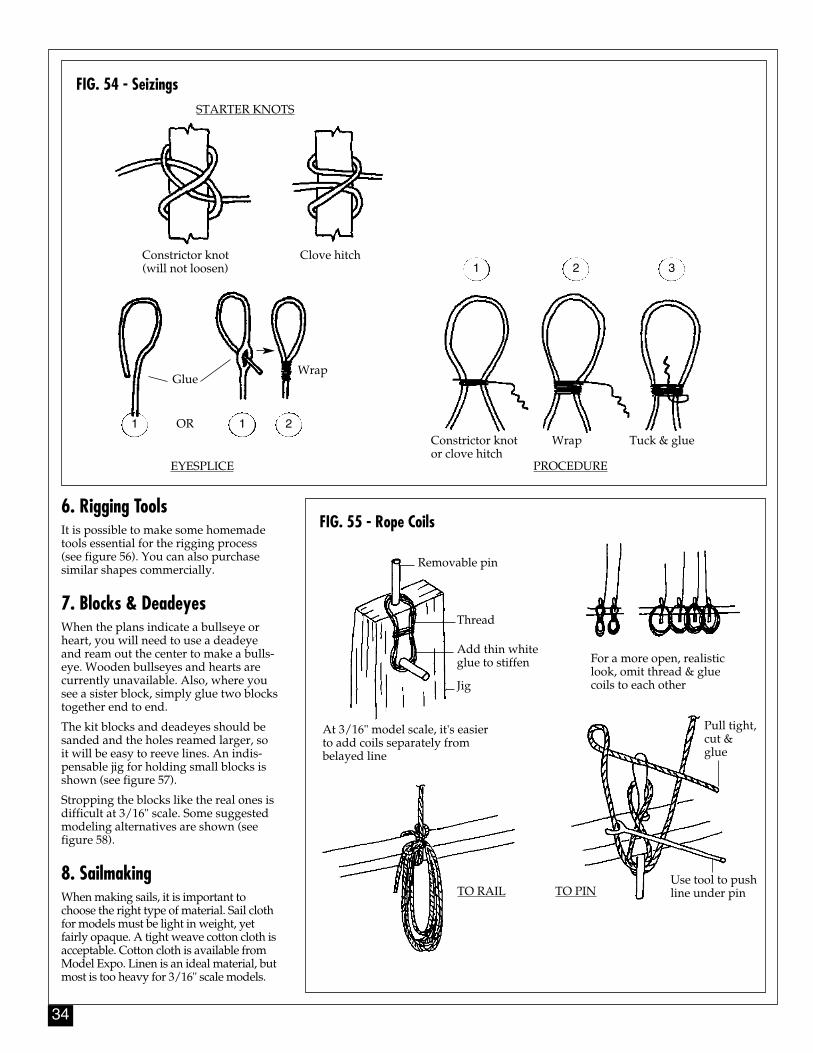
34
6. Rigging ToolsIt is possible to make some homemadetools essential for the rigging process(see figure 56). You can also purchasesimilar shapes commercially.
7. Blocks & DeadeyesWhen the plans indicate a bullseye orheart, you will need to use a deadeyeand ream out the center to make a bulls-eye. Wooden bullseyes and hearts arecurrently unavailable. Also, where yousee a sister block, simply glue two blockstogether end to end.
The kit blocks and deadeyes should besanded and the holes reamed larger, soit will be easy to reeve lines. An indis-pensable jig for holding small blocks isshown (see figure 57).
Stropping the blocks like the real ones isdifficult at 3/16" scale. Some suggestedmodeling alternatives are shown (seefigure 58).
8. SailmakingWhen making sails, it is important tochoose the right type of material. Sail clothfor models must be light in weight, yetfairly opaque. A tight weave cotton cloth isacceptable. Cotton cloth is available fromModel Expo. Linen is an ideal material, butmost is too heavy for 3/16" scale models.
FIG. 54 - Seizings
FIG. 55 - Rope Coils
STARTER KNOTS
Constrictor knot(will not loosen)
Clove hitch
EYESPLICE PROCEDURE
Constrictor knotor clove hitch
Wrap Tuck & glue
GlueWrap
Removable pin
Thread
Add thin whiteglue to stiffen
Jig
At 3/16" model scale, it's easierto add coils separately frombelayed line
For a more open, realisticlook, omit thread & gluecoils to each other
TO RAIL TO PIN
Pull tight,cut &glue
Use tool to pushline under pin
OR1 1 2
1 2 3
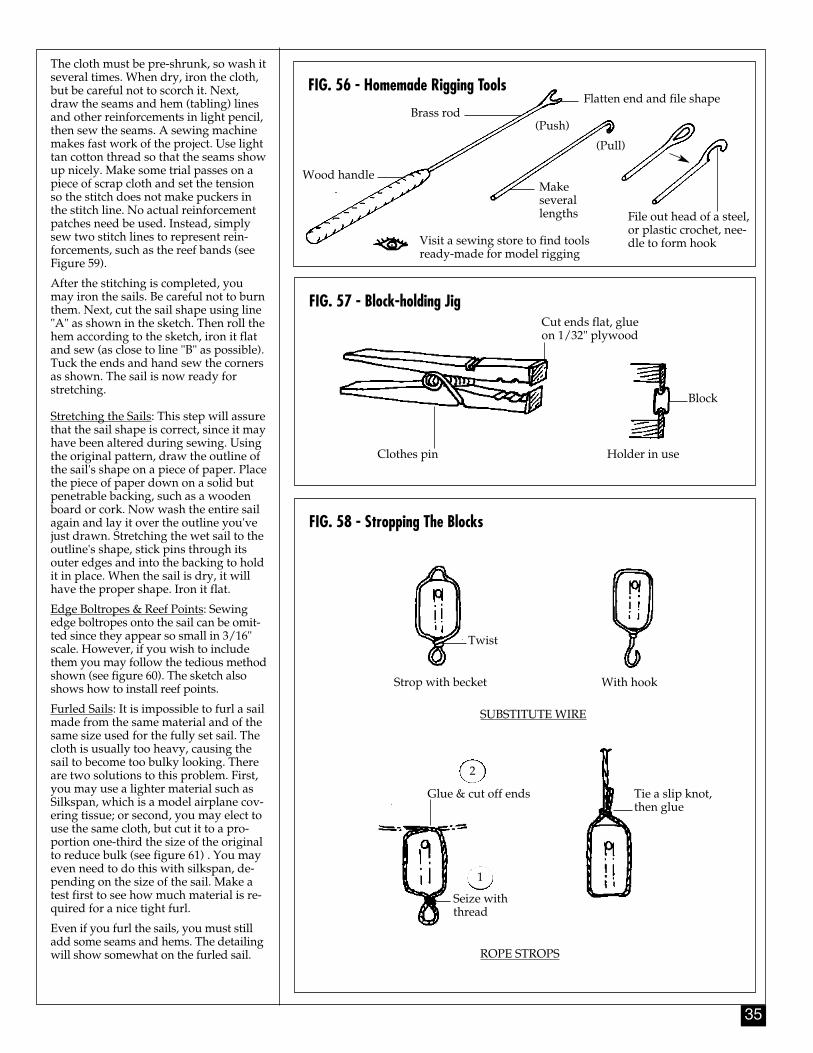
35
The cloth must be pre-shrunk, so wash itseveral times. When dry, iron the cloth,but be careful not to scorch it. Next,draw the seams and hem (tabling) linesand other reinforcements in light pencil,then sew the seams. A sewing machinemakes fast work of the project. Use lighttan cotton thread so that the seams showup nicely. Make some trial passes on apiece of scrap cloth and set the tensionso the stitch does not make puckers inthe stitch line. No actual reinforcementpatches need be used. Instead, simplysew two stitch lines to represent rein-forcements, such as the reef bands (seeFigure 59).
After the stitching is completed, youmay iron the sails. Be careful not to burnthem. Next, cut the sail shape using line"A" as shown in the sketch. Then roll thehem according to the sketch, iron it flatand sew (as close to line "B" as possible).Tuck the ends and hand sew the cornersas shown. The sail is now ready forstretching.
Stretching the Sails: This step will assurethat the sail shape is correct, since it mayhave been altered during sewing. Usingthe original pattern, draw the outline ofthe sail's shape on a piece of paper. Placethe piece of paper down on a solid butpenetrable backing, such as a woodenboard or cork. Now wash the entire sailagain and lay it over the outline you'vejust drawn. Stretching the wet sail to theoutline's shape, stick pins through itsouter edges and into the backing to holdit in place. When the sail is dry, it willhave the proper shape. Iron it flat.
Edge Boltropes & Reef Points: Sewingedge boltropes onto the sail can be omit-ted since they appear so small in 3/16"scale. However, if you wish to includethem you may follow the tedious methodshown (see figure 60). The sketch alsoshows how to install reef points.
Furled Sails: It is impossible to furl a sailmade from the same material and of thesame size used for the fully set sail. Thecloth is usually too heavy, causing thesail to become too bulky looking. Thereare two solutions to this problem. First,you may use a lighter material such asSilkspan, which is a model airplane cov-ering tissue; or second, you may elect touse the same cloth, but cut it to a pro-portion one-third the size of the originalto reduce bulk (see figure 61) . You mayeven need to do this with silkspan, de-pending on the size of the sail. Make atest first to see how much material is re-quired for a nice tight furl.
Even if you furl the sails, you must stilladd some seams and hems. The detailingwill show somewhat on the furled sail.
FIG. 56 - Homemade Rigging Tools
FIG. 57 - Block-holding Jig
FIG. 58 - Stropping The Blocks
Wood handle
Brass rodFlatten end and file shape
(Push)
(Pull)
Makeseverallengths File out head of a steel,
or plastic crochet, nee-dle to form hookVisit a sewing store to find tools
ready-made for model rigging
Clothes pin
Cut ends flat, glueon 1/32" plywood
Block
Holder in use
Twist
With hookStrop with becket
SUBSTITUTE WIRE
Glue & cut off ends
Seize withthread
ROPE STROPS
Tie a slip knot,then glue
1
2
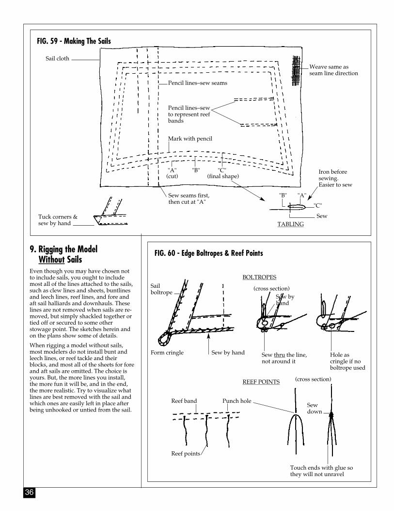
36
FIG. 59 - Making The Sails
9. Rigging the Model Without Sails
Even though you may have chosen notto include sails, you ought to includemost all of the lines attached to the sails,such as clew lines and sheets, buntlinesand leech lines, reef lines, and fore andaft sail halliards and downhauls. Theselines are not removed when sails are re-moved, but simply shackled together ortied off or secured to some otherstowage point. The sketches herein andon the plans show some of details.
When rigging a model without sails,most modelers do not install bunt andleech lines, or reef tackle and theirblocks, and most all of the sheets for foreand aft sails are omitted. The choice isyours. But, the more lines you install,the more fun it will be, and in the end,the more realistic. Try to visualize whatlines are best removed with the sail andwhich ones are easily left in place afterbeing unhooked or untied from the sail.
FIG. 60 - Edge Boltropes & Reef Points
Sail cloth
Pencil lines–sew seams
Pencil lines–sewto represent reefbands
Mark with pencil
Weave same asseam line direction
Tuck corners &sew by hand TABLING
Sew seams first,then cut at "A"
"A" "B" "C"(cut) (final shape)
"B" "A"
"C"
Sew
Iron beforesewing. Easier to sew
Sailboltrope
Sew by handForm cringle
BOLTROPES
Reef band
REEF POINTS
Punch hole
Reef points
Touch ends with glue sothey will not unravel
Sewdown
Sew thru the line,not around it
Hole ascringle if noboltrope used
Sew byhand
(cross section)
(cross section)
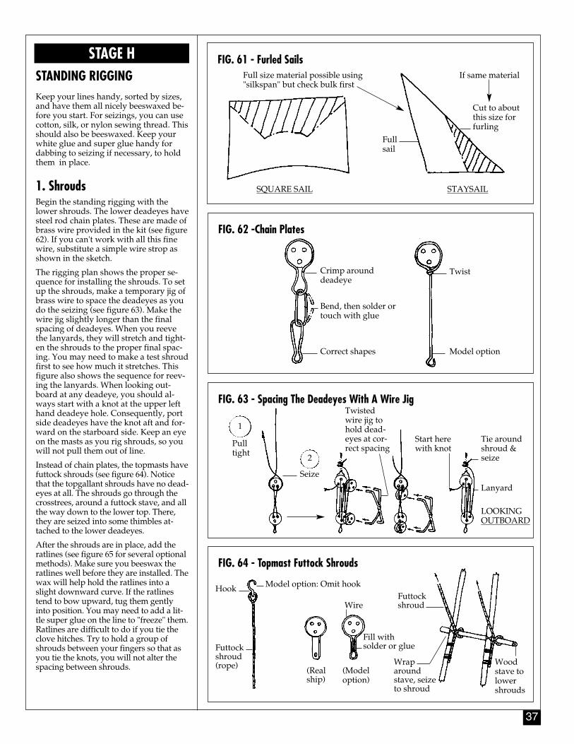
37
FIG. 61 - Furled Sails
FIG. 62 -Chain Plates
FIG. 63 - Spacing The Deadeyes With A Wire Jig
FIG. 64 - Topmast Futtock Shrouds
STAGE HSTANDING RIGGINGKeep your lines handy, sorted by sizes,and have them all nicely beeswaxed be-fore you start. For seizings, you can usecotton, silk, or nylon sewing thread. Thisshould also be beeswaxed. Keep yourwhite glue and super glue handy fordabbing to seizing if necessary, to holdthem in place.
1. Shrouds Begin the standing rigging with thelower shrouds. The lower deadeyes havesteel rod chain plates. These are made ofbrass wire provided in the kit (see figure62). If you can't work with all this finewire, substitute a simple wire strop asshown in the sketch.
The rigging plan shows the proper se-quence for installing the shrouds. To setup the shrouds, make a temporary jig ofbrass wire to space the deadeyes as youdo the seizing (see figure 63). Make thewire jig slightly longer than the finalspacing of deadeyes. When you reevethe lanyards, they will stretch and tight-en the shrouds to the proper final spac-ing. You may need to make a test shroudfirst to see how much it stretches. Thisfigure also shows the sequence for reev-ing the lanyards. When looking out-board at any deadeye, you should al-ways start with a knot at the upper lefthand deadeye hole. Consequently, portside deadeyes have the knot aft and for-ward on the starboard side. Keep an eyeon the masts as you rig shrouds, so youwill not pull them out of line.
Instead of chain plates, the topmasts havefuttock shrouds (see figure 64). Noticethat the topgallant shrouds have no dead-eyes at all. The shrouds go through thecrosstrees, around a futtock stave, and allthe way down to the lower top. There,they are seized into some thimbles at-tached to the lower deadeyes.
After the shrouds are in place, add theratlines (see figure 65 for several optionalmethods). Make sure you beeswax theratlines well before they are installed. Thewax will help hold the ratlines into aslight downward curve. If the ratlinestend to bow upward, tug them gentlyinto position. You may need to add a lit-tle super glue on the line to "freeze" them.Ratlines are difficult to do if you tie theclove hitches. Try to hold a group ofshrouds between your fingers so that asyou tie the knots, you will not alter thespacing between shrouds.
Full size material possible using"silkspan" but check bulk first
SQUARE SAIL STAYSAIL
Fullsail
Cut to aboutthis size forfurling
If same material
Crimp arounddeadeye
Bend, then solder ortouch with glue
Correct shapes Model option
Twist
Pulltight
Seize
2
Twistedwire jig tohold dead-eyes at cor-rect spacing
Tie aroundshroud &seize
Lanyard
LOOKINGOUTBOARD
Start herewith knot
Hook
Futtockshroud(rope)
Model option: Omit hook
Wire
Fill with solder or glue
(Realship)
(Modeloption)
Futtockshroud
Wraparoundstave, seizeto shroud
Woodstave tolowershrouds
1
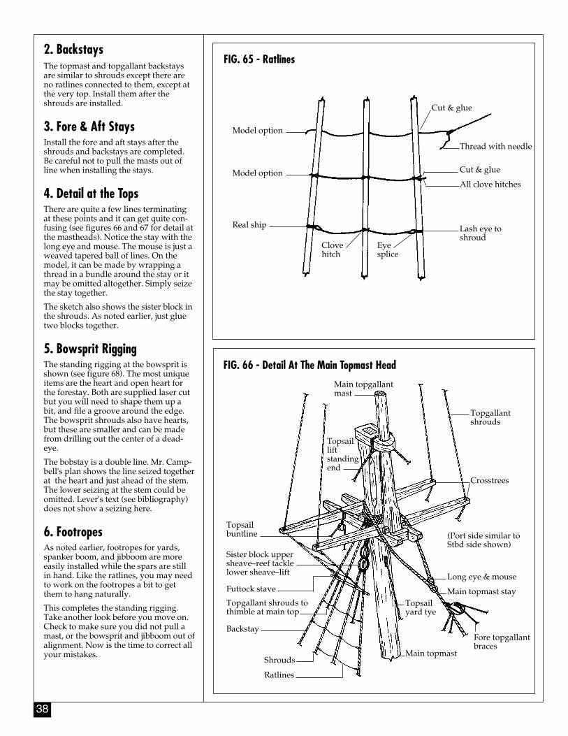
38
FIG. 66 - Detail At The Main Topmast Head
FIG. 65 - Ratlines2. BackstaysThe topmast and topgallant backstaysare similar to shrouds except there areno ratlines connected to them, except atthe very top. Install them after theshrouds are installed.
3. Fore & Aft StaysInstall the fore and aft stays after theshrouds and backstays are completed.Be careful not to pull the masts out ofline when installing the stays.
4. Detail at the TopsThere are quite a few lines terminatingat these points and it can get quite con-fusing (see figures 66 and 67 for detail atthe mastheads). Notice the stay with thelong eye and mouse. The mouse is just aweaved tapered ball of lines. On themodel, it can be made by wrapping athread in a bundle around the stay or itmay be omitted altogether. Simply seizethe stay together.
The sketch also shows the sister block inthe shrouds. As noted earlier, just gluetwo blocks together.
5. Bowsprit RiggingThe standing rigging at the bowsprit isshown (see figure 68). The most uniqueitems are the heart and open heart forthe forestay. Both are supplied laser cutbut you will need to shape them up abit, and file a groove around the edge.The bowsprit shrouds also have hearts,but these are smaller and can be madefrom drilling out the center of a dead-eye.
The bobstay is a double line. Mr. Camp-bell's plan shows the line seized togetherat the heart and just ahead of the stem.The lower seizing at the stem could beomitted. Lever's text (see bibliography)does not show a seizing here.
6. Footropes As noted earlier, footropes for yards,spanker boom, and jibboom are moreeasily installed while the spars are stillin hand. Like the ratlines, you may needto work on the footropes a bit to getthem to hang naturally.
This completes the standing rigging.Take another look before you move on.Check to make sure you did not pull amast, or the bowsprit and jibboom out ofalignment. Now is the time to correct allyour mistakes.
Model option
Model option
Real ship
Clovehitch
Eyesplice
Cut & glue
Thread with needle
Cut & glue
All clove hitches
Lash eye toshroud
Main topgallantmast
Topsailliftstandingend
Topsailbuntline
Topgallantshrouds
Crosstrees
(Port side similar toStbd side shown)
Long eye & mouse
Main topmast stay
Fore topgallantbraces
Main topmast
Topsailyard tye
Ratlines
Shrouds
Backstay
Topgallant shrouds tothimble at main top
Futtock stave
Sister block uppersheave–reef tacklelower sheave–lift
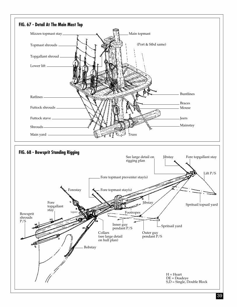
39
FIG. 67 - Detail At The Main Mast Top
FIG. 68 - Bowsprit Standing Rigging
Mizzen topmast stay Main topmast
(Port & Stbd same)Topmast shrouds
Topgallant shroud
Lower lift
Ratlines
Futtock shrouds
Futtock stave
Shrouds
Main yard Truss
Jeers
MouseBraces
Buntlines
BowspritshroudsP/S
Fore topgallantstay
(open)
Forestay
Bobstay
H = HeartDE = DeadeyeS,D = Single, Double Block
Collars (see large detailon hull plan)
Inner guy pendant P/S
Outer guy pendant P/S
Spritsail yard
Footropes
Jibstay
Fore topmast stay(s)
Fore topmast preventer stay(s)
Spritsail topsail yard
Lift P/S
Fore topgallant stayJibstaySee large detail on rigging plan
Mainstay
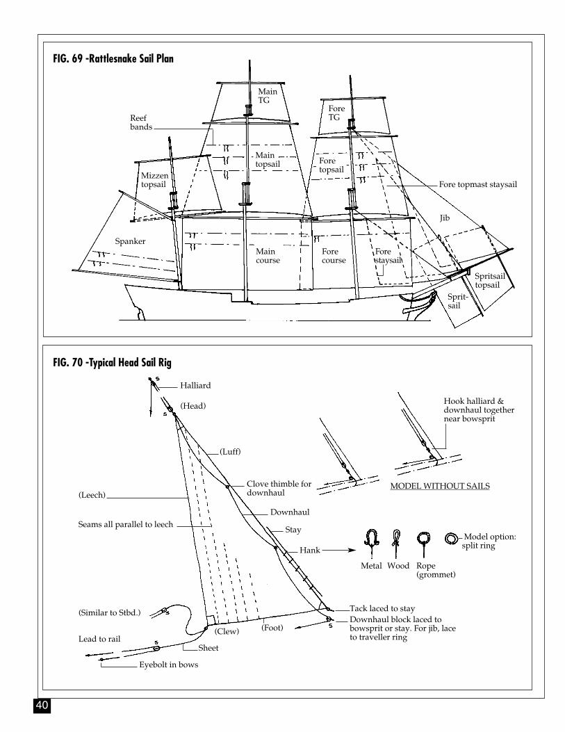
40
FIG. 69 -Rattlesnake Sail Plan
MainTG
ForeTGReef
bands
Mizzentopsail
Maintopsail Fore
topsail
Fore topmast staysail
Jib
Forestaysail
Forecourse
Maincourse
Spanker
Spritsailtopsail
Sprit-sail
FIG. 70 -Typical Head Sail Rig
Halliard
(Head)
(Luff)
Stay
Hook halliard &downhaul togethernear bowsprit
MODEL WITHOUT SAILS
Hank
Tack laced to stayDownhaul block laced tobowsprit or stay. For jib, laceto traveller ring
(Foot)(Clew)
SheetLead to rail
Clove thimble fordownhaul
Eyebolt in bows
(Similar to Stbd.)
Seams all parallel to leech
(Leech)
Metal Wood Rope(grommet)
Model option:split ring
Downhaul
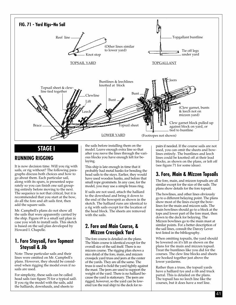
41
STAGE IRUNNING RIGGINGIt is now decision time. Will you rig withsails, or rig without? The following para-graphs discuss both choices and how togo about them. Each particular sail,along with its spars, is presented sepa-rately so you can finish one sail group-ing entirely before moving to the next.The sequence is not that critical, but it isrecommended that you start at the bow,do all the fore and aft sails first, thenadd the square sails.
Mr. Campbell's plans do not show allthe sails that were apparently carried bythe ship. Figure 69 is a small sail plan incase you wish to install sails. This sketchis based on the sail plan developed byHoward I. Chapelle.
1. Fore Staysail, Fore Topmast Staysail & Jib
Note: These particular sails and theirlines were omitted on Mr. Campbell'splans. However, they should be consid-ered when rigging the model even if nosails are used.
For simplicity, these sails can be calledhead sails (see figure 70 for a typical sail).If you rig the model with the sails, addthe halliards, downhauls, and sheets to
the sails before installing them on themodel. Leave enough extra line so thatafter you reeve the lines through the vari-ous blocks you have enough left for be-laying.
This ship is late enough in time that itprobably had metal hanks for bending thehead sails to the stays. Earlier, they wouldhave used wooden hanks, and before thatsmall rope grommets. In any case, for themodel, you may use a simple brass ring.
If sails are not used, attach the halliardto the downhaul and bring it down tothe end of the bowsprit as shown in thesketch. The halliard runs are identical toa rig with sails except for the location ofthe head block. The sheets are removedwith the sails.
2. Fore and Main Course, & Mizzen Crossjack Yard
The fore course is detailed on the plans.The Main course is identical except for theoverall size of the sail itself. There is nomizzen course. The rigging plan shows anice detail of the fore, main, and mizzencrossjack yard truss and jeers at the centerof the yards. They are all the same. Thetruss is used to hold the yard tightly againstthe mast. The jeers are used to support theweight of the yard. There is no halliard be-cause the yard is stationary. The jeers arerigged, however, so the yard can be low-ered (on the real ship) to the deck for re-
pairs if needed. If the course sails are notused, you can omit the sheets and bow-lines entirely. The buntlines and leechlines could be knotted off at their leadblocks, as shown on the plans, or left off(see figure 71 for some ideas).
3. Fore, Main & Mizzen TopsailsThe fore, main, and mizzen topsails are allsimilar except for the size of the sails. Theplans show details for the fore topsail.
The bowlines, and other lines obviouslygo to a different belaying point. The plansshow most of the lines except the bow-lines for the main and mizzen sails. Themain bowlines should go to a block at thetops and lower part of the fore mast, thendown to the deck for belaying. TheMizzen bowlines go to the main mast atsimilar points. For a better description ofthe sail lines, consult the Darcey Levertext listed in the bibliography.
When omitting topsails, the yard shouldbe lowered on it's lift as shown on theplans for the main and mizzen topsail.Treat the buntlines like you did for thecourses. The clew line blocks and sheetsare hooked together just above thelower yardarms.
Rather than a truss, the topsail yardshave a halliard tye and a rib and truckparral. This is detailed on the plans.The topsail has no leech line like thecourses, but it does have a reef line.
FIG. 71 - Yard Rigs–No Sail
TOPSAIL YARD TOPGALLANT
Knot stop
Reef line
(Other lines similar to lower yard) Tie off legs
under yard
Topgallant buntline
LOWER YARD
Brace
Topsail sheet & clew-line tied together
Clewline
Lift
Leech
Buntlines & leechlinesknotted at block
Bunt
Topsail sheet
Bunt
Clew garnet block pulled upagainst block on yard, ortied to buntline
(Clew garnet, bunts& leech not onmizzen yard)
Jeers
(Footropes not shown)
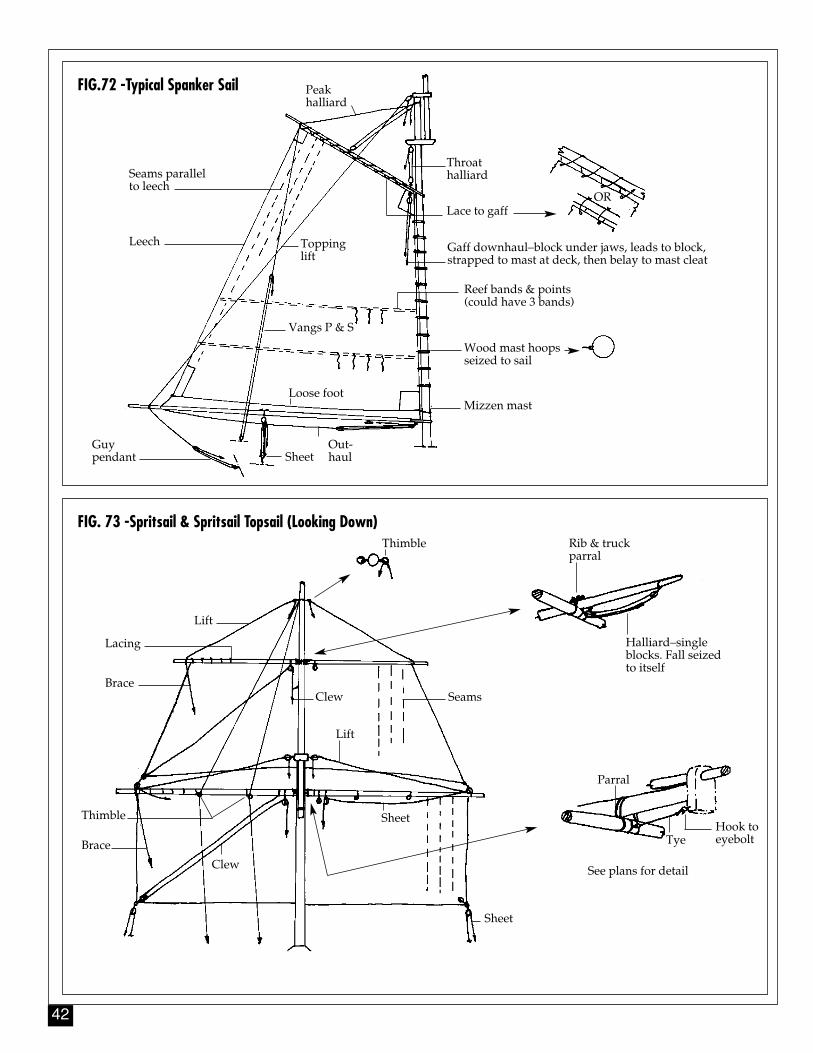
42
FIG. 73 -Spritsail & Spritsail Topsail (Looking Down)Thimble Rib & truck
parral
Halliard–singleblocks. Fall seizedto itself
Seams
Lift
Clew
Sheet
Sheet
See plans for detail
Parral
TyeHook toeyebolt
Lift
Lacing
Brace
Brace
Clew
Thimble
FIG.72 -Typical Spanker Sail Peak halliard
Toppinglift
Seams parallelto leech
Leech
Vangs P & S
Loose foot
Out-haulSheet
Guypendant
Mizzen mast
Wood mast hoopsseized to sail
Reef bands & points(could have 3 bands)
Throathalliard
Lace to gaffOR
Gaff downhaul–block under jaws, leads to block,strapped to mast at deck, then belay to mast cleat
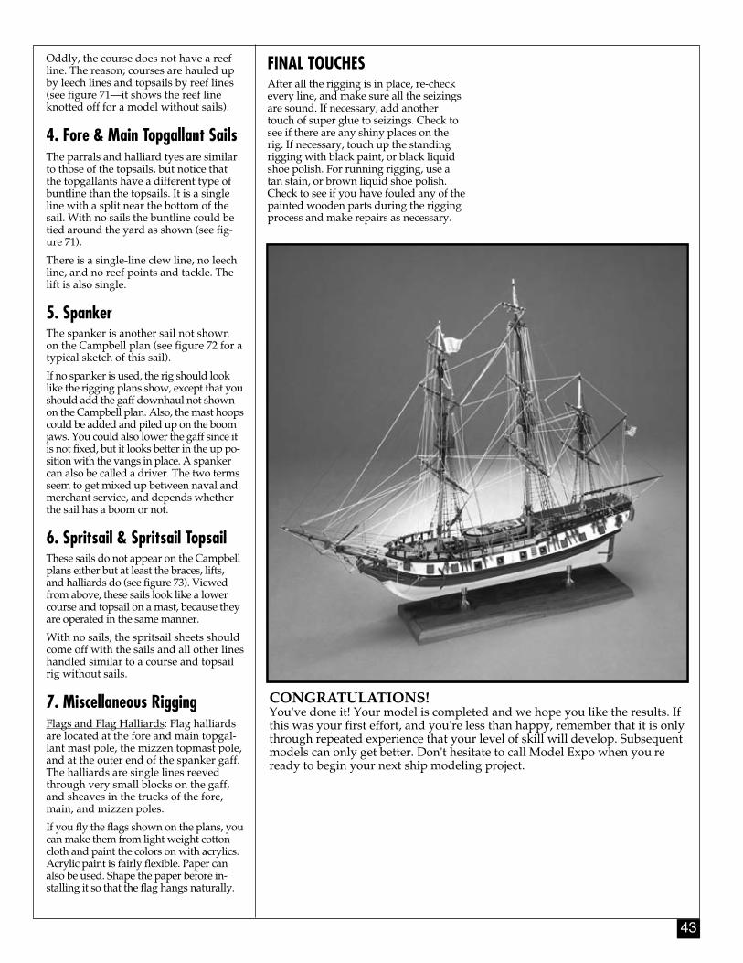
43
Oddly, the course does not have a reefline. The reason; courses are hauled upby leech lines and topsails by reef lines(see figure 71—it shows the reef lineknotted off for a model without sails).
4. Fore & Main Topgallant SailsThe parrals and halliard tyes are similarto those of the topsails, but notice thatthe topgallants have a different type ofbuntline than the topsails. It is a singleline with a split near the bottom of thesail. With no sails the buntline could betied around the yard as shown (see fig-ure 71).
There is a single-line clew line, no leechline, and no reef points and tackle. Thelift is also single.
5. SpankerThe spanker is another sail not shownon the Campbell plan (see figure 72 for atypical sketch of this sail).
If no spanker is used, the rig should looklike the rigging plans show, except that youshould add the gaff downhaul not shownon the Campbell plan. Also, the mast hoopscould be added and piled up on the boomjaws. You could also lower the gaff since itis not fixed, but it looks better in the up po-sition with the vangs in place. A spankercan also be called a driver. The two termsseem to get mixed up between naval andmerchant service, and depends whetherthe sail has a boom or not.
6. Spritsail & Spritsail TopsailThese sails do not appear on the Campbellplans either but at least the braces, lifts,and halliards do (see figure 73). Viewedfrom above, these sails look like a lowercourse and topsail on a mast, because theyare operated in the same manner.
With no sails, the spritsail sheets shouldcome off with the sails and all other lineshandled similar to a course and topsailrig without sails.
7. Miscellaneous Rigging Flags and Flag Halliards: Flag halliardsare located at the fore and main topgal-lant mast pole, the mizzen topmast pole,and at the outer end of the spanker gaff.The halliards are single lines reevedthrough very small blocks on the gaff,and sheaves in the trucks of the fore,main, and mizzen poles.
If you fly the flags shown on the plans, youcan make them from light weight cottoncloth and paint the colors on with acrylics.Acrylic paint is fairly flexible. Paper canalso be used. Shape the paper before in-stalling it so that the flag hangs naturally.
CONGRATULATIONS! You've done it! Your model is completed and we hope you like the results. Ifthis was your first effort, and you're less than happy, remember that it is onlythrough repeated experience that your level of skill will develop. Subsequentmodels can only get better. Don't hesitate to call Model Expo when you'reready to begin your next ship modeling project.
FINAL TOUCHESAfter all the rigging is in place, re-checkevery line, and make sure all the seizingsare sound. If necessary, add anothertouch of super glue to seizings. Check tosee if there are any shiny places on therig. If necessary, touch up the standingrigging with black paint, or black liquidshoe polish. For running rigging, use atan stain, or brown liquid shoe polish.Check to see if you have fouled any of thepainted wooden parts during the riggingprocess and make repairs as necessary.
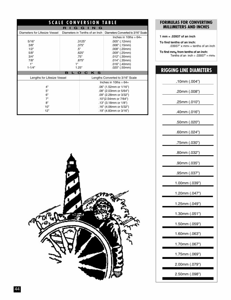
.20mm (.008")
.25mm (.010")
.40mm (.016")
.50mm (.020")
.60mm (.024")
.75mm (.030")
.80mm (.032")
.90mm (.035")
.95mm (.037")
1.00mm (.039")
1.20mm (.047")
1.25mm (.049")
1.30mm (.051")
1.50mm (.059")
1.60mm (.063")
1.70mm (.067")
1.75mm (.069")
2.00mm (.079")
2.50mm (.098")
.10mm (.004")
RIGGING LINE DIAMETERS
1 mm = .03937 of an inch
To find tenths of an inch:.03937" x mms = tenths of an inch
To find mms from tenths of an inch:Tenths of an inch ÷ .03937" = mms
FORMULAS FOR CONVERTING MILLIMETERS AND INCHES
44
Diameters in Tenths of an Inch Diameters Converted to 3/16" Scale
Inches in 10ths ÷ 64=5/16" .3125" .005" (.12mm)3/8" .375" .006" (.15mm)1/2" .5" .008" (.20mm)5/8" .625" .009" (.25mm)3/4" .75" .012" (.30mm)7/8" .875" .014" (.35mm)1" 1" .016" (.40mm)
1-1/4" 1.25" .020" (.50mm)
Inches in 10ths ÷ 64=
4" .06" (1.52mm or 1/16")5" .08" (2.03mm or 5/64")6" .09" (2.28mm or 3/32")7" .10"(2.54mm or 7/64")8" .13" (3.18mm or 1/8")10” .16" (4.06mm or 5/32")12” .19” (4.83mm or 3/16”)
Lengths for Lifesize Vessel Lengths Converted to 3/16” Scale
Diameters for Lifesize Vessel
S C A L E C O N V E R S I O N T A B L E
B L O C K S
R I G G I N G

BIBLIOGRAPHY
1. The History of American Sailing Ships, by Howard I. Chapelle. 1935 (Reprinted)Provides a complete description of Privateer ships, the hull lines, sail and other plans of Rattlesnake prepared by Mr. Chapelle from Admiralty draughts.
2. The Search for Speed Under Sail 1700-1855, by Howard I. Chapelle. 1967 (Reprinted). Additional information and drawings of Rattlesnake
3. The Young Sea Officers Sheet Anchor, by Darcey Lever.1819 (Reprinted) Contemporary rigging text and is a basis for the Model Shipways rigging plan reconstruction for Rattlesnake. Excellent drawings of the entire rig and sails. You should have this book if you intend to add sails to the ship.
4. Steel's Elements of Mastmaking and Rigging, by David Steel. 1794 (Reprinted)In addition to basic rigging discussions, this text contains sizes of rigging and blocks for various ships of the period. Tables for ships of 14 to 18 guns, 250 to 300 tons is adequate for Rattlesnake.
5. The Neophyte Shipmodeler's Jackstay, by George F. Campbell. 1962, Model Shipways. An excellent modeler's guide for period ships.
Note: Most books are available through Model Expo, Inc.Please check current catalog for availability.
45

46
MODELER'S LOGDate Time Notes

47
MODELER'S LOGDate Time Notes
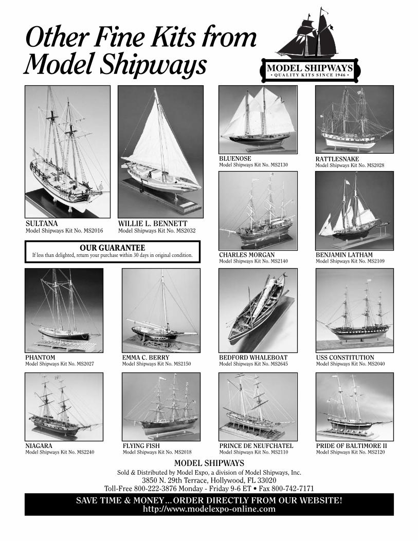
MODEL SHIPWAYSSold & Distributed by Model Expo, a division of Model Shipways, Inc.
3850 N. 29th Terrace, Hollywood, FL 33020Toll-Free 800-222-3876 Monday - Friday 9-6 ET • Fax 800-742-7171
SAVE TIME & MONEY...ORDER DIRECTLY FROM OUR WEBSITE!http://www.modelexpo-online.com
Other Fine Kits from Model Shipways
WILLIE L. BENNETTModel Shipways Kit No. MS2032
PHANTOMModel Shipways Kit No. MS2027
EMMA C. BERRYModel Shipways Kit No. MS2150
NIAGARAModel Shipways Kit No. MS2240
FLYING FISHModel Shipways Kit No. MS2018
CHARLES MORGANModel Shipways Kit No. MS2140
USS CONSTITUTIONModel Shipways Kit No. MS2040
PRINCE DE NEUFCHATELModel Shipways Kit No. MS2110
PRIDE OF BALTIMORE IIModel Shipways Kit No. MS2120
RATTLESNAKEModel Shipways Kit No. MS2028
BLUENOSEModel Shipways Kit No. MS2130
BENJAMIN LATHAMModel Shipways Kit No. MS2109
SULTANAModel Shipways Kit No. MS2016
OUR GUARANTEEIf less than delighted, return your purchase within 30 days in original condition.
BEDFORD WHALEBOATModel Shipways Kit No. MS2645