Rational Design of Metal Nanoframes for Catalysis and ...
13
www.MaterialsViews.com 2593 © 2015 Wiley-VCH Verlag GmbH & Co. KGaA, Weinheim www.small-journal.com Nanoframes Rational Design of Metal Nanoframes for Catalysis and Plasmonics Zhicheng Fang , Youcheng Wang , Chenxuan Liu , Sheng Chen, Wei Sang, Chao Wang,* and Jie Zeng* Recently, metal nanoframes have received increased attention due to their unique spatial and physicochemical, e.g., catalytic and plasmonic properties. So far, a variety of synthetic procedures have been developed to fabricate metal nanoframes with different shapes, sizes and compositions. Typical synthesis of metal nanoframes involves two stages: 1) formation of solid nanocrystals and 2) hollowing out the interiors and side faces. In this review, solution-phase synthetic strategies are summarized, based on galvanic replacement reactions, oxidative etching, the Kirkendall effect, electrodeposition, and template-assisted growth, as well as one-pot synthesis. Their potential applications in catalysis and optical sensing are overviewed as well. 1. Introduction ....................................... 2594 2. Synthetic Strategies ............................ 2594 3. Applications ....................................... 2601 4. Summary and Outlook ........................ 2603 From the Contents small 2015, 11, No. 22, 2593–2605
Transcript of Rational Design of Metal Nanoframes for Catalysis and ...

www.MaterialsViews.com
2593© 2015 Wiley-VCH Verlag GmbH & Co. KGaA, Weinheim www.small-journal.com
Nanoframes
Rational Design of Metal Nanoframes for Catalysis and Plasmonics Zhicheng Fang , Youcheng Wang , Chenxuan Liu , Sheng Chen , Wei Sang , Chao Wang , * and Jie Zeng *
Recently, metal nanoframes have received increased attention due to their unique spatial and physicochemical, e.g., catalytic and plasmonic properties. So far, a variety of synthetic procedures have been developed to fabricate metal nanoframes with different shapes, sizes and compositions. Typical synthesis of metal nanoframes involves two stages: 1) formation of solid nanocrystals and 2) hollowing out the interiors and side faces. In this review, solution-phase synthetic strategies are summarized, based on galvanic replacement reactions, oxidative etching, the Kirkendall effect, electrodeposition, and template-assisted growth, as well as one-pot synthesis. Their potential applications in catalysis and optical sensing are overviewed as well.
1. Introduction ....................................... 2594
2. Synthetic Strategies ............................ 2594
3. Applications ....................................... 2601
4. Summary and Outlook ........................ 2603
From the Contents
small 2015, 11, No. 22, 2593–2605

reviewswww.MaterialsViews.com
2594 www.small-journal.com © 2015 Wiley-VCH Verlag GmbH & Co. KGaA, Weinheim
DOI: 10.1002/smll.201402799
Z. Fang, Y. Wang, C. Liu, S. Chen, W. Sang, Prof. J. Zeng Hefei National Laboratory for Physical Sciences at the Microscale and Key Laboratory of Strongly-Coupled Quantum Matter Physics of Chinese Academy of Sciences Center of Advanced Nanocatalysis (CAN-USTC) and Department of Chemical PhysicsUniversity of Science and Technology of China Hefei , Anhui 230026 , P. R. China E-mail: [email protected]
Prof. C. Wang Department of Chemical and Biomolecular Engineering Johns Hopkins University Baltimore , Maryland 21218 , USA E-mail: [email protected]
1. Introduction
Hollow metal nanostructures have gained extensive atten-
tion in recent decades, owing to their unique physicochemical
properties that differ from their solid counterparts. They have
also been acknowledged for a variety of applications, such as
catalysis, optical sensing, and biomedicine. [ 1–9 ] So far, var-
ious morphologies of hollow metal nanocrystals have been
explored, including nanoboxes, nanocages, nanoframes, and
nanoshells. [ 10–17 ] Among those, nanoframes appear to have
the most open structure when compared with other types of
hollow nanostructures of similar sizes. In this work, “nanof-
rames” are referred as those nanocrystals composed of only
ridges without side faces. In addition, nanocages with large
cavity on side faces and nanodendrites consisting of multiple
sheets can be called nanoframes as well. [ 18–20 ]
To date, thanks to the efforts of many research groups,
various different shapes of nanoframes, including triangular,
cubic, octahedral, and decahedral nanoframes have been pre-
pared by either top-down or bottom-up methods. [ 21–24 ] For
instance, Xia and co-workers demonstrated the synthesis of
Au cubic nanoframes through a galvanic replacement reac-
tion between HAuCl 2 and Ag. [ 25 ] In addition, a one-pot pro-
cedure to synthesize complex Au–Ag octahedral nanoframes
has been proposed by Li and co-workers, [ 26 ] In general, syn-
thesis of metal nanoframes mainly involves two stages. The
fi rst stage is the nucleation and growth of solid particles. The
second stage is the hollowing out of the interiors and side
faces, which could be achieved through galvanic replacement
reactions or chemical etching. [ 22,27 ] The second stage, serving
a crucial role in the formation of nanoframes, comes with
certain challenges. Precise and selective removal of certain
facets (or certain metals, for bimetallic nanoframes) while
maintaining the frame structure is hard to achieve during
galvanic reactions or etching processes. If the power of cor-
rosion is too weak, hollowing could be incomplete, leading
to partially open structures such as nanoboxes or nanoc-
ages. [ 28 ] In contrast, with powers of corrosion that are too
strong, the nanoframes may be over-corroded and split into
separate fragments. [ 29 ] Additionally, there are a few cases that
take advantage of the Kirkendall effect to synthesize metal
nanoframes. [ 30,31 ]
Metal nanoframes possess unique spatial structures that
are promising for catalytic applications. [ 32–35 ] The 3D, net-
work-like nature of nanoframes is structurally distinct from
conventional high-surface-area heterogeneous catalysts. In
the latter case, the high surface-area-to-volume ratio is gained
by reducing the particle size, which inevitably deteriorates the
stability of the catalysts. Nanoframes, however, provide a way
to bypass this tradeoff. The removal of the non-functional
atoms, buried in the interior, raises the specifi c surface area
(per mass of metal) and improves the effi ciency of utilizing
the catalytic materials, particularly meaningful for scarce
and precious metals. Compared with polyhedral nanoparti-
cles of similar crystalline sizes (typically a few nanometers),
the converged edges in nanoframes usually exhibit substan-
tially enhanced thermal and chemical stability, partially due
to the large overall size of the 3D object inherited from the
solid particles formed in the fi rst stage of synthesis. Unlike
nanoboxes and nanoshells with enclosed exterior surface, the
open 3D structures of nanoframes allow for molecular access
to the interior surface atoms. This feature not only provides
the advantage of high surface-to-volume ratio, but also brings
about unconventional opportunities for tailoring the physical
and chemical properties of heterogeneous catalysts and for
achieving unprecedented catalytic performance.
In addition to excellent catalytic properties, their unique
and tunable optical properties—and in particular their local-
ized surface plasmon resonances (LSPR)—represent another
attractive characteristic exhibited by metal nanoframes. [ 36–38 ]
LSPR refers to the coherent oscillation of the free conduc-
tion band electrons in resonance with an incident electro-
magnetic fi eld. [ 38–42 ] The LSPR peaks depend on various
parameters, such as the shape, size, and dielectric environ-
ment of the nanoframe. [ 43–49 ] As observed by many groups,
decreasing the ridge thickness and/or increasing the edge
length will result in red-shifting of the resonance peak for
Au cubic nanoframes. [ 25,38 ] The tunable LSPR property will
render metal nanocrystals potentially useful in optical labels,
near-fi eld optical sensing, and as substrates for surface-
enhanced Raman spectroscopy (SERS). [ 38,50–52 ]
In this review, typical synthetic strategies of metal nanof-
rames are fi rst discussed. These strategies have been summa-
rized and classifi ed into three categories based on the relevant
mechanisms applied during the nanoframe formation pro-
cess: galvanic replacement reactions, oxidative etching, and
the Kirkendall effect. Subsequently, the experimental opera-
tion strategies are classifi ed into electrodeposition, template-
assisted growth, and one-pot synthesis. In order to highlight
the properties of metal nanoframes for remarkable applica-
tions in catalysis and optical sensing, a few examples are pre-
sented, before concluding with a summary and outlook.
2. Synthetic Strategies
2.1. Galvanic Replacement Reaction
It is well known that galvanic replacement reactions have
been widely employed as simple and effective routes to
synthesize metal nanocrystals with hollow interiors, including
small 2015, 11, No. 22, 2593–2605
www.MaterialsViews.com
2595© 2015 Wiley-VCH Verlag GmbH & Co. KGaA, Weinheim www.small-journal.com
nanoboxes, nanocages and nanoframes. [ 53,54 ] During a gal-
vanic replacement reaction, a template is oxidized and dis-
solved, while metal ions are reduced and the resultant atoms
are deposited on the surface of the template. The driving
force of the galvanic replacement reaction is the discrep-
ancy in redox potential between the two metal species. [ 55,56 ]
For instance, the reduction potential of AgCl/Ag (0.22 V vs
standard hydrogen electrode (SHE)) is more positive than
that of Zn 2+ /Zn (−0.76 V vs SHE). [ 57 ] Thus, oxidation of Zn
accompanied with reduction of AgCl can occur according to:
Zn(s) 2AgCl(s) Zn 2Cl 2Ag(s)2+ → + ++ −
(1)
Ag is often selected to serve as a sacrifi cial template in
many cases. [ 58–60 ] As a typical example, Xia and co-workers
reported the formation of Au-based nanoframes via galvanic
replacement reaction between Ag nanocubes and HAuCl 2 . [ 25 ]
The standard reduction potential of the AuCl 2 − /Au pair is
1.11 V (vs. SHE), which is higher than that of AgCl/Ag
(0.22 V vs. SHE). Thus, the Ag nanocubes can be oxidized
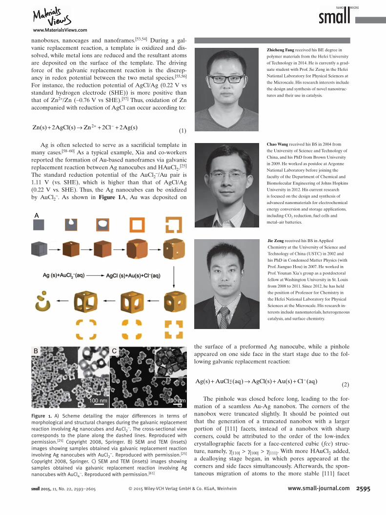
by AuCl 2 − . As shown in Figure 1 A, Au was deposited on
the surface of a preformed Ag nanocube, while a pinhole
appeared on one side face in the start stage due to the fol-
lowing galvanic replacement reaction:
Ag(s) AuCl (aq) AgCl(s) Au(s) Cl (aq)2+ → + +− −
(2)
The pinhole was closed before long, leading to the for-
mation of a seamless Au-Ag nanobox. The corners of the
nano box were truncated slightly. It should be pointed out
that the generation of a truncated nanobox with a larger
portion of {111} facets, instead of a nanobox with sharp
corners, could be attributed to the order of the low-index
crystallographic facets for a face-centered cubic ( fcc ) struc-
ture, namely, γ {110} > γ {100} > γ {111} . With more HAuCl 2 added,
a dealloying stage began, in which pores appeared at the
corners and side faces simultaneously. Afterwards, the spon-
taneous migration of atoms to the more stable {111} facet
Chao Wang received his BS in 2004 from
the University of Science and Technology of
China, and his PhD from Brown University
in 2009. He worked as postdoc at Argonne
National Laboratory before joining the
faculty of the Department of Chemical and
Biomolecular Engineering of Johns Hopkins
University in 2012. His current research
is focused on the design and synthesis of
advanced nanomaterials for electrochemical
energy conversion and storage applications,
including CO 2 reduction, fuel cells and
metal–air batteries.
Jie Zeng received his BS in Applied
Chemistry at the University of Science and
Technology of China (USTC) in 2002 and
his PhD in Condensed Matter Physics (with
Prof. Jianguo Hou) in 2007. He worked in
Prof. Younan Xia’s group as a postdoctoral
fellow at Washington University in St. Louis
from 2008 to 2011. Since 2012, he has held
the position of Professor for Chemistry in
the Hefei National Laboratory for Physical
Sciences at the Microscale. His research in-
terests include nanomaterials, heterogeneous
catalysis, and surface chemistry.
Zhicheng Fang received his BE degree in
polymer materials from the Hefei University
of Technology in 2014. He is currently a grad-
uate student with Prof. Jie Zeng in the Hefei
National Laboratory for Physical Sciences at
the Microscale. His research interests include
the design and synthesis of novel nanostruc-
tures and their use in catalysis.
small 2015, 11, No. 22, 2593–2605
Figure 1. A) Scheme detailing the major differences in terms of morphological and structural changes during the galvanic replacement reaction involving Ag nanocubes and AuCl 2 − . The cross-sectional view corresponds to the plane along the dashed lines. Reproduced with permission. [ 25 ] Copyright 2008, Springer. B) SEM and TEM (insets) images showing samples obtained via galvanic replacement reaction involving Ag nanocubes with AuCl 2 − . Reproduced with permission. [ 25 ] Copyright 2008, Springer. C) SEM and TEM (insets) images showing samples obtained via galvanic replacement reaction involving Ag nanocubes with AuCl 4 − . Reproduced with permission. [ 61 ]

reviewswww.MaterialsViews.com
2596 www.small-journal.com © 2015 Wiley-VCH Verlag GmbH & Co. KGaA, Weinheim
resulted in the enlargement of pores at the side faces, accom-
panied by shrinkage of pores at the corners. Continuous
migration resulted in the formation of a Au-based nanoframe
(Figure 1 B). When excess HAuCl 2 was added, the thickness
of ridges further decreased due to dealloying of Ag atoms
from the nanoframe. At a certain point, the ridges became
so fragile that the nanoframe collapsed into fragments as
a result. However, Xia and co-workers demonstrated that
when an aqueous solution of HAuCl 4 instead of HAuCl 2 was
added to react with the Ag nanocubes, Au-based nanocages
with scattered and small pores on the surface (Figure 1 C)
could be obtained according to:
+ → + +Ag(s) AuCl (aq) AgCl(s) Au(s) 3Cl (aq)4
– –
(3)
The standard reduction potential of the AuCl 4 − /Au pair
(0.99 V vs. SHE) is higher than that of AgCl/Ag (0.22 V vs.
SHE), so the Ag nanocubes can be oxidized in accordance
with ( 3) . The formation of Au-based nanoframes with a large
pore on each side face when employing AuCl 2 − contrasts to
that of Au-based nanocages with scattered and small pores on
the surface when employing AuCl 4 − , and this differencecan be
attributed to the amount of Au(0) being deposited per each
Ag(0) dissolved. It is known that AuCl 2 − generates one Au(0)
atoms per Ag(0) atom. As a result, the nanocages have much
thicker edges, and they are robust enough to resist etching to
form nanoframes during the dealloying process. On the other
hand, AuCl 4 − generates one Au(0) atom per every three
Ag(0) atoms. Thus, the edges of the nanocages are extremely
thin, and these nanocages would collapse into discrete parti-
cles easily instead of evolve into nanoframes during the deal-
loying process. [ 61 ]
In addition to cubic nanoframes, nanoframes with other
shapes can also be obtained through galvanic replace-
ment reactions. Li and co-workers reported the synthesis
of Au-Ag octahedral nanoframes through the reduction of
AgNO 3 by copper(I) chloride and octadecylamine (ODA) at
115 °C, and subsequent addition of an aqueous solution of
HAuCl 4 . [ 26 ] As shown in Figure 2 , a successive morphological
transition from truncated Ag polyhedrons to octahedral
hollow structures, and then to octahedral Au-Ag nanof-
rames, could be observed during the synthetic process. The
galvanic replacement reaction between Ag and HAuCl 4 ,
and selective deposition of resultant Au on the high-energy
{110} facets, resulted in the change from truncated Ag poly-
hedrons to hollow Au-Ag octahedrons. The appearance of
Au-Ag nanoframes was attributed to the fact that etching
of Ag by AuCl 4 − was easier for the stable {111} faces, while
etching of the Ag in the sides of the octahedron was more
diffi cult due to the covering of Ag with Au. When the reac-
tion time was further increased, AuCl 4 − and Ag + ions in the
solution were co-reduced by ODA, and the resultant Au and
Ag atoms selectively deposited on the corners of the octahe-
dral nanoframes.
Nanoframes for other metals, not just Au, can be pro-
duced through galvanic replacement reactions as well. For
instance, Tsuji et al. synthesized triangular Ag-Pd alloy nano-
frames by galvanic replacement reaction between triangular
Ag nanoplates and Na 2 PdCl 4, with post-treatment using
NaCl in an aqueous solution. [ 62 ] Recently, a similar example
has been reported by Kawazumi and co-workers, who synthe-
sized Pt-Ag alloy triangular nanoframes by galvanic replace-
ment reactions followed by saturated NaCl treatment in an
aqueous solution. [ 63 ]
In general, galvanic replacement reactions represent an
effective and universal route to synthesize metal nanoframes.
However, by far, most as-prepared nanoframes consist of
alloy shells. [ 28 ] For instance, reviewing the Au-based nano-
frames prepared through galvanic replacement reactions
between Ag nanocubes and HAuCl 2 , as presented in this sec-
tion, the elemental composition was found to be was 89% Au
and 11% Ag, as some Ag atoms could diffuse into the lattice
of deposited Au. [ 25 ] Besides, it is diffi cult to precisely control
small 2015, 11, No. 22, 2593–2605
Figure 2. A) Schematic illustration of the deduced process of Au−Ag octahedral nanoframe formation. B) TEM image of Ag particles. C−E) TEM images of the products at different reaction times after HAuCl 4 is added: C) 40 s, D) 20 min, and E) 60 min. Reproduced with permission. [ 26 ] Copyright 2012, American Chemical Society.

www.MaterialsViews.com
2597© 2015 Wiley-VCH Verlag GmbH & Co. KGaA, Weinheim www.small-journal.com
the ridge thickness of as-prepared nanoframes, as the gal-
vanic replacement reaction involves dissolution of the tem-
plate structures accompanied with simultaneous deposition
on the surface of templates. [ 28 ]
2.2. Oxidative Etching
The formation of metal nanoframes through etching mainly
involves selective dissolution of less stable elements and/
or certain facets of the nanostructures with an appropriate
etchant. Xia and co-workers synthesized cubic nanof-
rames consisting of pure Au by adding a certain amount of
Fe(NO 3 ) 3 to selectively dissolve Ag from Au-Ag nanoboxes,
made through galvanic replacement reaction between Ag
nanocubes and HAuCl 4 ( Figure 3 ). [ 28 ] An aqueous solution of
Fe(NO 3 ) 3 can react with Ag according to
Ag(s) Fe(NO ) (aq) AgNO (aq) Fe(NO ) (aq)3 3 3 3 2+ → +
(4)
Compared with the above protocol involving galvanic
replacement reaction during the dealloying process, this new
procedure allows more precise control over the ridge thick-
ness and extent of hollowing of the resultant nanoframes. This
could be attributed to the absence of concurrent deposition
of Au in the dealloying process when using Fe(NO 3 ) 3 solu-
tion. It is known that Ag may not be completely etched away,
due to the better etching resistance of Ag in the Ag-Au
alloy than in pure Ag particles. This point has been proven
by the observation that Ag atoms could not be completely
extracted from Au/Ag alloy nanoboxes containing 30% Au,
reacting with Fe(NO 3 ) 3 . However, with the continuous addi-
tion of an aqueous Fe(NO 3 ) 3 solution, etching of nanoboxes
with an atomic percentage of Au as low as 15%, could yield
resultant products with an increased atomic ratio of 100:1
Au/Ag. [ 28 ] This observation is similar to the partial dissolu-
tion of Ag from a Au/Ag alloy with nitric acid reported by
Espiell and co-workers, but the exact explanation remains
elusive. [ 64 ] When NH 4 OH was used as a wet etchant instead
of Fe(NO 3 ) 3 , a mixture of nanocages and nanoframes was
obtained. The difference in morphology results from dif-
ferent strengths of etchants. When NH 4 OH is used, Au atoms
can diffuse onto and passivate the Au/Ag alloy surface before
complete removal of Ag atoms, as NH 4 OH is a much weaker
etchant than Fe(NO 3 ) 3 . [ 65 ]
In addition to Fe(NO 3 ) 3 and NH 4 OH mentioned above,
O 2 is another common etchant. Previously, O 2 was used to
synthesize hollow iron oxide and cobalt oxide nanoparticles
through controlled oxidation of iron and cobalt nanoparticles,
respectively. [ 66,67 ] Recently, Chen et al. demonstrated the syn-
thesis of Pt 3 Ni nanoframes based on the corrosion of PtNi 3
nanoparticles in the presence of O 2. First, they synthesized
PtNi 3 polyhedrons with a uniform rhombic dodecahedral
morphology. [ 35 ] Then, the PtNi 3 polyhedrons were dispersed
in hexanes and kept under ambient conditions for 2 weeks,
affording Pt 3 Ni nanoframes. This evolution process could be
accelerated by increasing the temperature to 120 °C. Finally,
after dispersion of nanoframes onto carbon supports, and
subsequent thermal treatment, Pt 3 Ni nanoframes/C catalysts
with Pt-skin surfaces were obtained. The schematic illustra-
tions and corresponding transmission electron microscope
(TEM) images of the samples at representative stages are
presented in Figure 4 . The evolution from PtNi 3 solid poly-
hedrons to Pt 3 Ni nanoframes was ascribed to preferential
oxidation of Ni on the facets by O 2 , and dissolution of the
formed nickel oxides in the presence of oleylamine ligands. [ 68 ]
It is important to point out that the preferential etching in
this process originated from the enrichment of Pt along the
edges of the initial PtNi 3 particles, whereas the mechanism
causing the uneven element distribution during the growth of
solid PtNi 3 nanoparticles remains elusive.
Other oxidative etching routes include utilization of
molten salt corrosion. [ 69 ] In general, the key to formation
of nanoframes by oxidative etching is to control the speed
and selectivity of etching. While the former is usually deter-
mined by the power of the etchant (e.g., chemical potential
and concentration), reaction temperature, and similar factors,
selective etching is usually more challenging and involves
complicated mechanisms. Above all other parameters, the
small 2015, 11, No. 22, 2593–2605
Figure 3. Schematic drawing and SEM images showing the formation of a Au cubic nanoframe. A) The schematic drawing for the formation of a Au cubic nanoframe. B) SEM image of an initial Ag nanocube; C) SEM image of a Au–Ag alloy nanobox obtained by reacting Ag nanocube with 4.0 mL of 0.2 m M HAuCl 4 aqueous solution; D,E) SEM images of the nanocage and nanoframe obtained by reacting the nanobox with 10 and 20 mL of 50 m M aqueous Fe(NO 3 ) 3 solution, respectively. Reproduced with permission. [ 28 ] Copyright 2007, American Chemical Society.
Figure 4. Schematic illustrations and corresponding TEM images of the products obtained at four representative stages during the evolution process from polyhedra to nanoframes. A) Initial solid PtNi 3 polyhedra. B) PtNi intermediates. C) Final hollow Pt 3 Ni nanoframes. D) Annealed Pt 3 Ni nanoframes with Pt(111)-skin-like surfaces dispersed on high-surface area carbon. Reproduced with permission. [ 35 ] Copyright 2014, AAAS.

reviewswww.MaterialsViews.com
2598 www.small-journal.com © 2015 Wiley-VCH Verlag GmbH & Co. KGaA, Weinheim
power of the etchant seems to play a particularly important
role: required to be neither too weak to accomplish complete
corrosion/dealloying, nor too strong to diminish the selec-
tivity and tear the nanoframes into fragments.
When employing either galvanic replacement reaction
or oxidative etching, facet control is an inescapable problem.
For a solid particle covered by only one type of facet, both
galvanic replacement reactions and oxidative etching are
expected to take place on this facet. When more than one
type of facet is present on the surface of a solid particle, how-
ever, these two strategies can proceed with facet selectivity,
which has signifi cant connections with the surface energies
of different facets. It has been established that the surface
free energies of low-index facets of an fcc noble-metal crystal
decrease in the order of γ {110} > γ {100} > γ {111} . When a clean
polyhedron with no capping agent on the surface is employed
as the template for a galvanic replacement reaction or oxida-
tive etching, the dissolution of atoms should begin from the
{110} and {100} facets due to their higher surface free energy.
However, a facet-specifi c capping agent is often intentionally
introduced to cover the surface of a nanocrystal during its
synthesis, which can alter the surface free energies of various
facets, and even reverse their order. [ 53 ] Huang and co-workers
have investigated chemical etching of Ag 2 O nanocrystals by
NH 3 solution and NaOH. They pointed out that the order of
facet stability was found to be {111} > {110} > {100} due to the
less effective adsorption of hydroxide ions on the {100} faces.
As a result, the {100} facets are more susceptible to etching
in comparison to other facets. [ 70,71 ] In addition to the cap-
ping agents, other factors such as reaction kinetics and twin
defects can all affect the facet selectivity and thus deserve
careful study.
2.3. Kirkendall Effect
The Kirkendall effect is a vacancy-mediated mechanism
based on the observation of a net mass-fl ow of a faster dif-
fusing species, balanced by the opposing fl ow of vacancies
that condense into voids in solids. [ 72,73 ] It is a diffusion pro-
cess involved in many synthetic processes of hollow and
porous nanocrystals. [ 74–76 ] González et al. applied sequen-
tial galvanic replacement and Kirkendall effect reactions at
room temperature to obtain polymetallic hollow nanocrys-
tals with very different morphologies and compositions, such
as double-walled Au-Ag nanoboxes, trimetallic Pd-Au-Ag
nanoboxes and cylindrical hollow nanostructures. With small
modifi cations to the synthetic protocol, they could also pro-
duce metal nanoframes, a kind of hollow nanocrystal. [ 30 ]
Very recently, Han et al. presented a unique structure trans-
formation phenomenon for the fabrication of Cu 3 Pt alloy nano-
frames with polyhedral morphology. This strategy starts with the
preparation of polyhedral Cu–Pt nanoparticles with a core-shell
construction—formed by anisotropic growth of Pt on multiply
twinned Cu seed particles—which are subsequently trans-
formed into Cu 3 Pt alloy nanoframes due to the Kirkendall effect
between the Cu core and Pt shell. After the structural evolution,
the as-prepared Cu 3 Pt alloy nanoframes possess the rhombic
dodecahedral morphology of their core–shell parents. [ 31 ]
2.4. Electrodeposition
Electrodeposition refers to the deposition of a substance on a
substrate/electrode with the participation of electric current.
In many works, electrodeposition has been employed to pre-
pare solid particles with low porosity. [ 77 ] For instance, Pullini
et al. reported the fabrication of Co/Cu-multilayer-nanowire
arrays by pulsed electrodeposition into nanoporous polymer
templates. [ 78 ] In this section, we focus on the preparation of
metal nanoframes based on electrodeposition coupled with
other methods, such as electroleaching and chemical etching.
Moghimi et al. demonstrated a unique route for synthesis
of bimetallic FeNi nanoframes (nanocages with large cavity
on each side face) through electrodeposition of FeNi parti-
cles from an electrolyte containing NiCl 2 and FeCl 2 , followed
by the process of electroleaching. [ 79 ] With increasing deposi-
tion time from 3 to 20 s, they observed that the morpholog-
ical evolution of FeNi particles went from spherical particles
to truncated cubes, to cubes with sharp corners, and fi nallyto
concave cubes ( Figure 5 A). Cl − and Ni 2+ ions in the solution
increase the reduction rate of Fe 2+ ions, leading to a kinetically
controlled process of formation of concave nanocubes with
exposed high-index facets. Later on, FeNi nanoframes were
obtained by a controlled electroleaching process, hollowing
out the interiors of the concave nanocubes. Since the point of
highest surface energy is located at the center of the concave
face, leaching and dissolution started at this site and continued
to the edges until the center was completely hollowed out.
Scanning electron microscope (SEM) images of the concave
nanoframes obtained after one, two, and three cyclic voltam-
metry (CV) cycles are shown in Figure 5 B–D, respectively.
Electrodeposition coupled with chemical etching can also
be used to synthesize nanoframes. For instance, Okazaki et al.
prepared Au nanoframes through selective electrodeposition of
Au atoms on the edges and vertices of Ag cubes modifi ed with
small 2015, 11, No. 22, 2593–2605
Figure 5. A) SEM images of typical FeNi nanocubes with increasing deposition time from 3 to 20 s. B–D) SEM images of FeNi nanocages obtained after one, two, and three CV cycles in a 10 m M PBS solution at pH 3 and a scan rate of 50 mV s −1 , respectively. Reproduced with permission. [ 79 ] Copyright 2013, American Chemical Society.

www.MaterialsViews.com
2599© 2015 Wiley-VCH Verlag GmbH & Co. KGaA, Weinheim www.small-journal.com
1-octanethiol, followed by chemical etching of the resulting par-
ticles with an aqueous solution containing H 2 O 2 and H 2 SO 4 . [ 80 ]
2.5. Template-assisted Growth
Templating is a universal method of fabricating metal
nanocrystals with various structures. For instance, Yu
et al. synthesized Au@Pd concave nanocrystals enclosed by
high-index Pd facets in the presence of Au trisoctahedrons
as the template. [ 81 ] Xia and co-workers used a 3D porous
lattice consisting of uniform iron particles as a template to
generate gold multipods. [ 82 ] During the formation of nanof-
rames through template-assisted growth, the template serves
as a scaffold and desirable materials can be added onto it (or
generated in situ). Afterwards, an additional reaction stage
is designed to remove the template completely. The as-pre-
pared nanoframes can have shape and size corresponding to
those of the parental template.
Xia and co-workers demonstrated a simple and effective
route for synthesis of cubic Rh nanoframes through selective
removal of Pd cores of the Pd–Rh nanocubes with Fe(III)/Br −
pairs as a wet etchant ( Figure 6 ). [ 22 ] In this approach, Pd nano-
cubes served as a template. Site-specifi c nucleation and growth
of Rh atoms at the corners and edges of the template resulted
in the formation of Pd–Rh bimetallic nanocubes with a core–
frame structure and concave side face. Selective adsorption of
excess Br − on the {100} side faces of preformed Pd cubic seeds,
together with kinetically controlled growth achieved by adding
Na 3 RhCl 6 , slowly led to preferential nucleation and selective
growth at the corners and edges. Br − also plays a crucial role in
the dealloying process. Complete etching of Pd nanocrystals is
hard to achieve in the absence of Br − , because the difference
in the standard reduction potentials between Fe(III)/Fe(II)
and PdCl 4 2− /Pd pairs is too small (0.18 V vs SHE) to realize
complete etching. When excess Br − was added into the solu-
tion, the complete removal of Pd cubic cores can be achieved
because the difference in the standard reduction potentials
between Fe(III)/Fe(II) and PdBr 4 2− /Pd pair is much higher
(0.28 V vs SHE), and the etching can occur according to
+ + + →
+ +
Pd(s) 2Fe (aq) 4Br (aq) PdBr (aq)
2Fe (aq)
3+ –
4
2–
2
(5)
Recently, a similar route to synthesize ultrathin triangular
gold nanoframes was demonstrated by Shahjamali et al. [ 21 ] In
this method, Au atoms that were generated through reducing
HAuCl 4 with hydroxylamine were selectively deposited on
the edges of triangular Ag nanoplates. Etching of silver in the
presence of a mixture solution containing H 2 O 2 and NH 4 OH
was then performed.
Plate-like nanoframes can be considered as nanoplates
having only edges, and no top or bottom faces. Jang et al.
synthesized plate-like Pt nanoframes using Au nanoplates
as a template. [ 83 ] They coated Ag atoms on the template
and selectively etched Au and Ag from the core with dilute
aqua regia. In this method, the galvanic replacement reaction
between Ag atoms and Pt 4+ primarily occurs at the edges,
instead of the terraces, of nanoplates and Ag + ions play the
role of electron shuttle for Pt 4+ .
Another typical example is the synthesis of ultrathin gold
nanoframes through surfactant-free templating of pentagonal
Ag nanocrystals, which was reported by McEachran et al. [ 24 ]
In this approach, they performed selective deposition of Au
atoms onto the decahedral silver templates, followed by dis-
solution of Ag from the Au-coated decahedra with H 2 O 2 . The
morphological evolution and TEM images of samples at dif-
ferent stages were shown in Figure 7 . It should be noted that
different products were obtained when using gold-coated
decahedrons containing different amounts of gold. Specifi -
cally, Au-based nanocages retaining some gold at both facets
and edges were generated after reacting H 2 O 2 with gold-
coated decahedrons in which the amount of deposited gold
was more than ca. 15% Au/Ag (where X% Au/Ag represents
X molar percentage of gold relative to the silver present in
the template). However, for the decahedrons in which the
amount of deposited gold was less than ca. 15% Au/Ag , the
frame remained predominantly gold after treatment with
H 2 O 2 . Dissolution and redeposition of Ag took place at a
lower concentration of peroxide solution (approximately
0.05 m), forming Au–Ag alloy nanoframes. When using Ag
templates with pentagonal twinning and {111} facets, such
as icosahedrons and pentagonal faceted rods, corresponding
nanoframes could also be synthesized using this procedure.
From the above examples, one can clearly see that a
template method usually involves two major steps: growth
of desirable metal on a preformed template, and removal of
the template. A signifi cant advantage of this method is that
small 2015, 11, No. 22, 2593–2605
Figure 6. A) TEM image of Rh cubic nanoframes obtained by selectively etching away the Pd cores from the Pd–Rh core–frame nanocubes; B,C) TEM images of Rh cubic nanoframes projected along <100> and <110> zone axes, respectively; and D) drawings showing 3D models of a Rh cubic nanoframe and its projections along <100>, <110>, and <111> zone axes. Reproduced with permission. [ 22 ]

reviewswww.MaterialsViews.com
2600 www.small-journal.com © 2015 Wiley-VCH Verlag GmbH & Co. KGaA, Weinheim
the morphology of the resulting nanoframes could be easily
tuned by using templates with different shapes.
2.6. One-pot Synthesis
Although fabricating metal nanoframes with a one-pot
method is simple and promising, there are far fewer reports
regarding this method than templating. Among a variety
of nanoframes synthesized using a one-pot strategy, Pt–
Cu alloy nanoframes have been widely studied. [ 14,18,20 ]
Recently, Zheng and co-workers reported the fabrication
of unique excavated rhombic dodecahedral (ERD) PtCu 3
alloy nanocrystals ( Figure 8 ) by co-reduction of the metal
precursors Pt(acac) 2 and Cu(acac) 2 in the presence of
N,N-dimethylformamide (DMF), cetyltri-
methylammonium chloride (CTAC) and
n -butylamine. [ 20 ] The authors observed
that ERD PtCu 3 nanocrystals were gener-
ated at the very early stage and then grew
larger and larger as the reaction was pro-
longed. This evolution is totally different
from the growth–etching process of the
formation of metal nanoframes. The amine
group in n -butylamine can selectively
adsorb on {111} facets, leading to the dif-
ferent rates of growth along the <100> and
<111> directions. Using a larger amount
of n -butylamine, the area of exposed {110}
facets on the resultant nanocrystals could
be enlarged as well. Thus, a proper amount
of n -butylamine is key to the formation
of the ERD PtCu 3 alloy nanocrystals. It
should be noted that the as-prepared ERD
PtCu 3 nanocrystals are not conventional
nanoframes with no side faces; they can be
considered as frameworks constructed of
24 ultrathin nanosheets with high-energy
{110} facets. Lou and co-workers demon-
strated a one-pot solvothermal method to
synthesize highly concave Pt nanoframes
with an analogous shape. [ 84 ] Specifi cally, a solution containing
H 2 PtCl 6 , oleylamine (OAm) and DMF underwent ultrasoni-
cation and heating at 160 °C for 12 h, and the resultant Pt
nanoframes were enclosed by high-index {740} facets.
In addition to ERD alloy nanocrystals, cubic PtCu 3 nano-
frames (nanocages with large cavities on each side face)
could be generated using a one-pot method as well. Lou and
co-workers reported the generation of PtCu 3 nanoframes
through dissolution of H 2 PtCl 6 ·6H 2 O, Cu(acac) 2, and cetyl-
trimethylammonium bromide (CTAB) in OAm, with subse-
quent heating of the solution at 170 °C for 24h. [ 18 ] A typical
high-magnifi cation TEM image of the as-prepared PtCu 3
nanoframes is shown in Figure 9 A. As the standard reduc-
tion potential of Cu(II)/Cu (0.34 V vs SHE) is more negative
small 2015, 11, No. 22, 2593–2605
Figure 8. A) SEM image of the ERD PtCu 3 NCs on a large scale. B) SEM images, C) high-magnifi cation TEM images showing an individual ERD PtCu 3 alloy NC with different orientations. Insets to (C) show the corresponding selected area electron diffraction patterns. D) Schematic models of an ERD PtCu 3 alloy NC viewed along the <110>, <100>, and <111> directions. Reproduced with permission. [ 20 ] Copyright 2014, American Chemical Society.
Figure 9. A) High-magnifi cation TEM image of PtCu 3 cubic nanoframes and, inset, the corresponding model image. Adapted with permission. [ 18 ] Copyright 2012, American Chemical Society. B) TEM image of octahedral Pt–Cu nanoframes; top-right inset shows a high-magnifi cation TEM image of octahedral Pt–Cu nanoframes, and the bottom-left inset shows the corresponding model image. Reproduced with permission. [ 14 ] Copyright 2013, Royal Society of Chemistry.
Figure 7. A) Illustration showing the formation of gold nanoframes and nanocages upon deposition of gold onto decahedral Ag-NPs, and subsequent silver dissolution with hydrogen peroxide. B) TEM image of silver decahedra prior to gold deposition. C) TEM image of silver decahedra after deposition of gold. D) TEM image of the frames after dissolution of silver with hydrogen peroxide. The amounts of gold deposited relative to silver in the template AgNPs were 5 mol%. All scale bars are 50 nm. Reproduced with permission. [ 24 ] Copyright 2011, American Chemical Society.
www.MaterialsViews.com
2601© 2015 Wiley-VCH Verlag GmbH & Co. KGaA, Weinheim www.small-journal.com
than that of Pt(II)/Pt (1.18 V vs SHE), Pt 2+ should be
reduced fi rst. However, the authors proposed that Cu 2+ ions
are reduced fi rst to form Cu nanocrystals, because CTAB
could affect the reduction rates of Pt 2+ and Cu 2+ ions. Then,
the galvanic replacement reaction between Cu nanocrystals
and H 2 PtCl 6 occurs spontaneously, leading to the formation
of PtCu 3 hollow nanocages. Another similar example is the
one-pot fabrication of single-crystalline octahedral Pt–Cu
nanoframes (Figure 9 B) demonstrated by Nosheen et al. [ 14 ]
In this approach, CuCl 2 , H 2 PtCl 6 ·6H 2 O, PVP glycine, NaI,
and ethanolamine were respectively added to water, with the
aqueous solution then heated at 200 °C for 2 h. Cu nanocrys-
tals are formed ahead of Pt nanocrystals, as the presence of
glycine above a certain threshold amount could infl uence the
reduction rates of Pt 2+ and Cu 2+ ions. Afterwards, a galvanic
replacement reaction between Cu nanocrystals and H 2 PtCl 6
ions is responsible for the formation of octahedral Pt–Cu
nanoframes.
3. Applications
3.1. Catalysis
Noble metals are widely used as catalysts in various chem-
ical reactions. [ 85,86 ] A number of efforts have been made to
enhance the performance of noble-metal catalysts, including
tailoring their size, shape and composition. [ 87 ] Due to the
unique spatial structure, nanoframes have the advantages of
having large specifi c surface areas, high thermal and chemical
stability, as well as unconventional surface atomic structures
and 3D molecular accessibility. [ 35 ] Therefore, nanoframes
made of noble metals have attracted great attention for cata-
lytic applications.
The large specifi c surface areas of metal nanoframes usu-
ally give enhanced catalytic activity compared with their nan-
oparticulate counterparts. Li et al. applied single-crystalline
octahedral Au–Ag nanoframes (discussed in Section 2.1) as
catalysts for the synthesis of azobenzene from aniline. [ 26 ] A
yield of 94% was obtained when the reaction was catalyzed by
the Au–Ag nanoframes, while the yield was only 31% with the
same amount of Au–Ag particles (with a diameter of ≈10 nm).
Furthermore, the catalytic performance of metal nanoframes
is strongly dependent on their surface structure. [ 88 ] Zheng
et al. measured the catalytic properties of ERD nanocrys-
tals with {110} facets preferrentially exposed, edge-concave
octahedral PtCu 3 nanocrystals enclosed by {110} and {111}
facets, octahedral PtCu 3 nanocrystals with {111}, and com-
mercial Pt black. The metal nanocrystals with different facets
often have distinct atomic bonding and surface activity. It was
observed that the ERD PtCu 3 alloy nanocrystals with {110}
surface showed the highest electrocatalytic activity, which was
attributed to the smaller average coordination number of the
atoms on this facet. [ 20 ] Although bimetallic nanoframes often
exhibit excellent catalytic performance, detailed analysis and
explanation regarding the catalytic properties of bimetallic
nanoframes still deserve further work.
Electrochemical reactions, such as the oxygen reduction
reaction (ORR) at the cathode of fuel cells and metal–air
batteries, play a vital role in the development of renewable
energy technologies. To raise the effi ciency of electrical–
chemical energy conversion and enable the large-scale
implementation of these technologies, the catalytic activity
and durability need to be substantially improved from cur-
rent commercial electrocatalysts. [ 88–91 ] Very recently, Chen et
al. reported a signifi cantly improved performance of Pt 3 Ni
nanoframes (see Figure 4 ) compared with nanoparticulated
PtNi/C and commercial Pt/C catalysts in the ORR. [ 35 ] The
activity of different electrocatalysts follows the order: Pt/C
< PtNi/C << Pt 3 Ni nanoframes, as shown by the polarization
curves given in Figure 10 A. The Pt 3 Ni nanoframes exhibited
an improvement factor of >16 in specifi c activity (Figure 10 C)
and 22 in mass activity (Figure 10 D) versus commercial
Pt/C catalysts (both at 0.95 V vs. reversible hydrogen elec-
trode (RHE)). The extraordinarily high specifi c activity of the
Pt 3 Ni nanoframes likely arises from the formation of the two-
monolayer thick Pt-skin surface on the nanoframes, induced
by controlled thermal treatment without destroying the 3D
nanostructure, as well as the open structure of the Pt 3 Ni
nanoframes that allows access of the reactant molecules to
both the internal and external surface atoms. Furthermore,
the Pt 3 Ni nanoframes were also shown to facilitate the incor-
poration of ionic liquids, e.g., [MTBD][NTf 2 ], into the elec-
trocatalyst; further boosted catalytic activity was observed
on the nanoframes/ionic liquid composite catalysts. Here the
open 3D structure of the nanoframe is more effi cient in fi xing
the ionic liquid than nanoparticulated catalysts, such as com-
mercial Pt/C. The ionic liquid possesses high O 2 solubility and
increases the O 2 concentration on the catalyst surface, raising
the ORR activity. [ 32,34 ] Overall, the ionic liquid-encapsulated
Pt 3 Ni nanoframes exhibited an improvement factor of 22 in
specifi c activity and 36 in mass activity versus Pt/C catalysts.
In addition, the Pt 3 Ni nanoframes were shown to be highly
active for the hydrogen evolution reaction after surface mod-
ifi cation with electrochemically deposited Ni(OH) 2 clusters,
with enhancement of almost one order of magnitude relative
to Pt/C (Figure 10 B).
3.2. Optical Properties and Applications
Metal nanoframes have unique optical properties, due to
their localized surface plasmon resonances (LSPR), involving
the coherent oscillation of the free conduction band electrons
in resonance with an incident electromagnetic fi eld. [ 38–42 ]
In comparison to other morphologies, metal nanoframes
have distinct LSPR properties. Cheng and co-workers have
investigated the plasmon modes of Ag nanoboxes, nanoc-
ages, and nanoframes. The results show that the plasmon
modes (dipole and quadrupole) of a single Ag nanocage are
red-shifted relative to the nanobox as the surface porosity of
the nanocage increases. In particular, the wavelengths at the
peaks of these modes almost linearly depend on the surface
porosity: the larger the surface porosity, the more the red-
shifted these modes. For a Ag nanoframe whose hole length
on the side faces is larger than half of the edge length, the
dipole mode is within the near-infrared regime. [ 92 ] Xia and
co-workers observed UV–vis spectra of the intermediate
small 2015, 11, No. 22, 2593–2605

reviewswww.MaterialsViews.com
2602 www.small-journal.com © 2015 Wiley-VCH Verlag GmbH & Co. KGaA, Weinheim
products prepared through the galvanic replacement reac-
tion between Ag nanocubes and different amounts of
HAuCl 2 (discussed in Section 2.1). [ 25 ] During the synthetic
process, a signifi cant LSPR red-shifting of the intermediates
was observed with increasing amounts of HAuCl 2 as shown
in Figure 11 A. In addition, they summarized the scattering
spectra of the as-prepared gold nanoframes in Figure 11 B
with the SEM images of the corresponding nanoframes
in the inset. As the ratio R between the outer edge length
and the ridge thickness increased, the peak position was
red-shifted. This is because an increase in edge length or a
decrease in ridge thickness increases the charge separation,
leading to the reduction of the restoring force for electron
oscillation. In addition to the size, it is established that the
composition has signifi cant effects on the LSPR properties
as well. For instance, Polavarapu et al. reported that the
morphological and compositional changes involved in the
galvanic replacement reaction between Ag nanocubes and
HAuCl 4 in organic media led to changes in the LSPR of
the resultant Au–Ag particles. With the continuous addition
of HAuCl 4 into the reaction mixture, the fi nal Ag/Au molar
ratios in the products increases,and signifi cant LSPR red-
shifts can be observed. However, excess addition of HAuCl 4
leads to a blue shift due to fragmentation of the hollow
nanostructures. [ 36 ]
Due to the unique and tunable LSPR property, nano-
frames have potential applications in optical sensing.
Mahmoud et al. studied the sensing effi ciency of gold nano-
frames prepared using Ag nanocube templates to react
with HAuCl 4 . [ 38 ] The effi ciency of a near-infrared sensor is
measured by the sensitivity factor S , which is defi ned as the
shift in the wavelength of the surface plasmon resonance
(SPR) peak position (in nanometers) per unit change in
the refractive index (RIU) of the surrounding medium.
The shift of the SPR peak position of gold nanoframes
can refl ect the change in the dielectric constant of the
surrounding environment when the shape, size, and inter-
particle separation are fi xed. Figure 11 C shows the SPR
spectra of gold nanoframes with a wall length L of 42 nm
and a wall thickness T of 9 nm assembled as monolayers
on the surface of quartz substrates measured in different
solvents. It can be clearly seen that gold nanoframes have
different peaks in different surroundings. Specifi cally, with
increasing refractive index of the solvent, a red shift of the
SPR for these nanoframes was observed. The relationship
between the refractive index of the solvent and the SPR
peak maximum of Au nanoframes was found to be linear.
With increasing the aspect ratio L / T of the Au nanof-
rames, the sensitivity factors (the slopes of the straight
lines between λ max and the refractive index) also increased.
The strong surface plasmonic fi elds of hollow nanoframes,
resulting from the coupling between the surface plasmonic
fi elds on the exterior and interior walls, may be related to
the high sensitivity factors of gold nanoframes.
small 2015, 11, No. 22, 2593–2605
Figure 10. Electrochemical properties of Pt 3 Ni nanoframes. A) Cyclic voltammograms of Pt/C and Pt 3 Ni/C nanoframes signify the difference in surface coverage by H upd and OH ad . Electrochemically active surface area (ECSA) of the nanoframes is determined by integrated charge of adsorbed CO electro-oxidation curve. B) Hydrogen evolution reaction (HER) activities for Pt/C, Pt/Ni(OH) 2 /C, Pt 3 Ni nanoframes/C, and Pt 3 Ni frames/Ni(OH) 2 /C in alkaline electrolyte. C,D) Specifi c (C) and mass (D) activities measured at 0.95 V, and improvement factors versus Pt/C catalysts. Because of the high intrinsic activity of the Pt 3 Ni nanoframes, the ORR activity values are given at 0.95 V in order to avoid the extensive error margin at 0.9 V introduced by the close proximity of current values to the diffusion-limited current. Note: IL is shorthand for ionic liquid. Reproduced with permission. [ 35 ] Copyright 2014, AAAS.

www.MaterialsViews.com
2603© 2015 Wiley-VCH Verlag GmbH & Co. KGaA, Weinheim www.small-journal.com
4. Summary and Outlook
During the past decade, metal nanoframes have received
increasing attention due to their unique spatial structures
and physicochemical properties. Substantial progress has
been made in both controlled synthesis and demonstra-
tion of functional applications of metal nanoframes. In this
review, we summarized fi ve categories of typical synthetic
strategies for nanoframes: 1) galvanic replacement reaction,
2) oxidative etching, 3) Kirkendall effect, 4) electrodeposi-
tion, 5) template-assisted growth, and 6) one-pot synthesis.
It has been shown that nanoframes with diverse morpholo-
gies for different metals, including triangular Au–Pd, cubic
Rh, octahedral Au–Ag, and rhombic dodecahedral Pt 3 Ni
nanoframes have been obtained through the above strate-
gies. Applications of these open, three-dimensional nano-
structures have been discussed in terms of catalysis and
optical sensing. It has been illustrated that metal nano-
frames usually possess superior catalytic properties in
chemical reactions and a high sensitivity factor in optical
sensing.
Despite the progress that has been
made, challenges are still present in the
controlled synthesis of metal nanoframes
for tuning the degree of hollowing, thick-
ness of ridges, and elemental composition.
In particular, controlling the ridge thick-
ness of metal nanoframes is of great signif-
icance since this parameter is unique and
critical to catalytic and plasmonic proper-
ties. One feasible route is the tuning of the
thickness of deposited metals on a tem-
plate by adjusting the relative amount of
metal precursors and templates. Another
practical route is adjustment of the cer-
tain parameters, including temperature,
etching time, type and amount of addi-
tives, and so on, during the etching pro-
cess to control the extent to which solid
particles are hollowed out. Fundamental
understanding of the growth mechanisms
of nanoframes is yet to be developed,
which has limited the selectivity in carving
the three-dimensional morphology. To
overcome these challenges, integration
of different synthetic strategies, e.g., tem-
plate growth and oxidative etching, as
discussed in section 2.5, or development
of new methods, is needed. Theoretical
studies for simulation of the nanostruc-
ture evolution during the synthesis, which
to a large extent are still missing, would
also be important for gaining insight into
the process of nanoframes formation, and
providing guidance for the future studies.
Meanwhile, production of nanoframes so
far has mostly been limited to the mil-
ligram scale. The present yields are obvi-
ously insuffi cient for meeting industrial
demands for catalytic materials. Therefore, another focus of
future work should be on exploiting more robust synthesis
that could enable the scaled-up production of nanoframes.
Although they have been demonstrated to be advanta-
geous in catalysis and optical sensing, the structure–prop-
erty relationships of metal nanoframes in these applications
are yet to be established and understood. Though it is clear
that the factors that have signifi cant effects on the catalysis
are complicated and entangled with each other, classifi ca-
tion of the catalytic functions has not, in most cases, discov-
ered the extent to which this is the case. More related work
towards this question is expected in the future. Besides the
demonstrated applications, the open three-dimensional
nanostructures could be utilized to load drug and biological
molecules for targeted delivery. The facilitated formation of
composite nanostructures with other materials, as demon-
strated in the case of Pt 3 Ni nanoframes/ionic liquid, could also
be exploited for other catalytic reactions. With the continu-
ation and growth of research into metal nanoframes, futher
functionalites and more promising performances in existing
functionalities may be expected for various applications.
small 2015, 11, No. 22, 2593–2605
Figure 11. A) UV–vis spectra taken from aqueous suspensions of the structures synthesized by titrating Ag nanocubes with 1 mL to 6 mL of 0.1 m M /L AuCl 2 − . Reproduced with permission. [ 25 ] Copyright 2008, Springer. B) Scattering spectra of individual Au nanoframes and corresponding SEM. Reproduced with permission. [ 25 ] Copyright 2008, Springer. C) SPR of 42 nm wall-length and 9 nm wall-thickness Au nanoframe monolayers assembled on the surface of quartz substrates and measured in different solvents. Reproduced with permission. [ 38 ] Copyright 2010, American Chemical Society. D) Relationship between the refractive index and the SPR peak maximum of Au nanoframes with different aspect ratios. This fi gure also shows that the values of the sensitivity factors (determined from the slope of each line for each aspect ratio) are 620 ± 15, 516 ± 24, 508 ± 33, and 409 ± 6 for nanoframes of aspect ratios 5.1, 4.6, 4.3, and 3.2, respectively. Reproduced with permission. [ 38 ] Copyright 2010, American Chemical Society.

reviewswww.MaterialsViews.com
2604 www.small-journal.com © 2015 Wiley-VCH Verlag GmbH & Co. KGaA, Weinheim
[26] X. Hong , D. Wang , S. Cai , H. Rong , Y. Li , J. Am. Chem. Soc. 2012 , 134 , 18165 .
[27] D. Wan , X. Xia , Y. Wang , Y. Xia , Small 2013 , 9 , 3111 . [28] X. Lu , L. Au , J. McLellan , Z.-Y. Li , M. Marquez , Y. Xia , Nano Lett.
2007 , 7 , 1764 . [29] S. E. Skrabalak , J. Chen , Y. Sun , X. Lu , L. Au , C. M. Cobley , Y. Xia ,
Acc. Chem. Res. 2008 , 41 , 1587 . [30] E. González , J. Arbiol , V. F. Puntes , Science 2011 , 334 , 1377 . [31] L. Han , H. Liu , P. Cui , Z. Peng , S. Zhang , J. Yang , Sci. Rep. 2014 , 4 ,
6414 . [32] J. Snyder , T. Fujita , M. W. Chen , J. Erlebacher , Nat. Mater. 2010 , 9 ,
904 . [33] J. Snyder , I. McCue , K. Livi , J. Erlebacher , J. Am. Chem. Soc. 2012 ,
134 , 8633 . [34] J. Snyder , K. Livi , J. Erlebacher , Adv. Funct. Mater. 2013 , 23 , 5494 . [35] C. Chen , Y. Kang , Z. Huo , Z. Zhu , W. Huang , H. L. Xin , J. D. Snyder ,
D. Li , J. A. Herron , M. Mavrikakis , M. Chi , K. L. More , Y. Li , N. M. Markovic , G. A. Somorjai , P. Yang , V. R. Stamenkovic , Sci-ence 2014 , 343 , 1339 .
[36] L. Polavarapu , L. M. Liz-Marzán , Nanoscale 2013 , 5 , 4355 . [37] M. A. Mahmoud , M. A. El-Sayed , Nano Lett. 2009 , 9 , 3025 . [38] M. A. Mahmoud , M. A. El-Sayed , J. Am. Chem. Soc. 2010 , 132 ,
12704 . [39] S. Zou , G. C. Schatz , Chem. Phys. Lett. 2005 , 403 , 62 . [40] S. J. Oldenburg , R. D. Averitt , S. L. Westcott , N. J. Halas , Chem.
Phys. Lett. 1998 , 288 , 243 . [41] H. Wang , D. W. Brandl , P. Nordlander , N. J. Halas , Acc. Chem. Res.
2007 , 40 , 53 . [42] P. K. Jain , X. Huang , I. H. El-Sayed , M. A. El-Sayed , Acc. Chem. Res.
2008 , 41 , 1578 . [43] J. Zhao , A. O. Pinchuk , J. M. McMahon , S. Li , L. K. Ausman ,
A. L. Atkinson , G. C. Schatz , Acc. Chem. Res. 2008 , 41 , 1710 . [44] L. J. Sherry , R. Jin , C. A. Mirkin , G. C. Schatz , R. P. Van Duyne , Nano
Lett. 2006 , 6 , 2060 . [45] I. H. El-Sayed , X. Huang , M. A. El-Sayed , Nano Lett. 2005 , 5 , 829 . [46] A. J. Haes , S. Zou , G. C. Schatz , R. P. Van Duyne , J. Phys. Chem. B
2004 , 108 , 109 . [47] J.-J. Storhoff , A.-A. Lazarides , R.-C. Mucic , C.-A. Mirkin ,
R.-L. Letsinger , G.-C. Schatz , J. Am. Chem. Soc. 2000 , 122 , 4640 . [48] A. J. Haes , S. Zou , G. C. Schatz , R. P. Van Duyne , J. Phys. Chem. B
2004 , 108 , 6961 . [49] J. Zhao , A. J. Haes , X. Zhang , S. Zou , E. M. Hicks , G. C. Schatz ,
R. P. Van Duyne , in MRS Symp. Proc., Vol. 900 (Eds: C-J. Zhong , N. A. Kotov , W. Daniell , F. P. Zamborini ), Cambridge University Press , Cambridge, UK 2006 .
[50] A. J. Haes , C. L. Haynes , A. D. McFarland , G. C. Schatz , R. R. Van Duyne , S. L. Zou , MRS Bull. 2005 , 30 , 368 .
[51] A. D. McFarland , R. P. Van Duyne , Nano Lett. 2003 , 3 , 7426 . [52] C. L. Haynes , R. P. Van Duyne , J. Phys. Chem. B. 2003 , 107 , 7426 . [53] X. Xia , Y. Wang , A. Ruditskiy A , Y. Xia , Adv. Mater. 2013 , 25 , 6313 . [54] X. Teng , Q. Wang , P. Liu , W. Han , A. I. Frenkel , W. Wen ,
N. Marinkovic , J. C. Hanson , J. A. Rodriguez , J. Am. Chem. Soc. 2008 , 130 , 1093 .
[55] Y. Sun , Y. Xia , J. Am. Chem. Soc. 2004 , 126 , 3892 . [56] Y. Sun , B. Mayers , Y. Xia , Adv. Mater. 2003 , 15 , 641 . [57] G. Inzelt , Encyclopedia of Electrochemistry , Vol. 7 (Eds: A. J. Bard ,
M. Stratmann , F. Scholz , C. J. Pickett ), Wiley-VCH , Weinheim, Germany 2006 , p. 43 .
[58] H. M. Chen , R. S. Liu , M. Y. Lo , S. C. Chang , L. D. Tsai , Y. M. Peng , J. F. Lee , J. Phys. Chem. C 2008 , 112 , 7522 .
[59] N. R. Sieb , N. C. Wu , E. Majidi , R. Kukreja , N. R. Branda , B. D. Gates , ACS Nano 2009 , 3 , 1365 .
[60] M. H. Kim , X. Lu , B. Wiley , E. P. Lee , Y. Xia , J. Phys. Chem. C 2008 , 112 , 7872 .
[61] L. Au , X. Lu , Y. Xia , Adv. Mater. 2008 , 20 , 2517 . [62] M. Tsuji , T. Kidera , A. Yajima , M. Hamasaki , M. Hattori , T. Tsuji ,
H. Kawazumi , CrystEngComm 2014 , 16 , 2684 .
Acknowledgments
This work was supported by Collaborative Innovation Center of Suzhou Nano Science and Technology, MOST of China (2014CB932700 and 2011CB921403), SRG-HSC, NSFC under Grant Nos. 21203173, 51371164, 51132007 and J1030412, Strategic Priority Research Program B of the CAS under Grant No. XDB01020000, and Fundamental Research Funds for the Central Universities (WK2340000050 and WK2060190025). In addition, C. W. thanks the start-up support from the Whiting School of Engi-neering, and funding support from NSF.
[1] S.-W. Kim , M. Kim , W. Y. Lee , T. Hyeon , J. Am. Chem. Soc. 2002 , 124 , 7642 .
[2] H. M. Chen , R. S. Liu , M. Y. Lo , S. C. Chang , L. D. Tsai , Y. M. Peng , J. F. Lee , J. Phys. Chem. C. 2008 , 112 , 7522 .
[3] H. Zhang , M. Jin , H. Liu , J. Wang , M. J. Kim , D. Yang , Z. Xie , J. Liu , Y. Xia , ACS Nano 2011 , 5 , 8212 .
[4] S. Lal , S. Link , N. J. Halas , Nat. Photonics 2007 , 1 , 641 . [5] J. Zeng , J. Huang , W. Lu , X. Wang , B. Wang , S. Zhang , J. Hou , Adv.
Mater. 2007 , 19 , 2172 . [6] W. Li , X. Cai , C. Kim , G. Sun , Y. Zhang , R. Deng , M. Yang , J. Chen ,
S. Achilefu , L. V. Wang , Y. Xia , Nanoscale 2011 , 3 , 1724 . [7] K. Niikura , N. Iyo , Y. Matsuo , H. Mitomo , K. Ijiro , ACS Appl. Mater.
Interfaces 2013 , 5 , 3900 . [8] S. Shukla , A. Priscilla , M. Banerjee , R. R. Bhonde , J. Ghatak ,
P. V. Satyam , M. Sastry , Chem. Mater. 2005 , 17 , 5000 . [9] C. Zhou , T. H. Tsai , D. C. Adler , H. C. Lee , D. W. Cohen ,
A. Mondelblatt , Y. Wang , J. L. Connolly , J. G. Fujimoto , Opt. Lett. 2010 , 35 , 700 .
[10] B. T. Sneed , C. N. Brodsky , C. H. Kuo , L. K. Lamontagne , Y. Jiang , Y. Wang , F. Tao , W. Huang , C. K. Tsung , J. Am. Chem. Soc. 2013 , 135 , 14691 .
[11] A. Popa , A. C. S. Samia , Chem. Commun. 2014 , 50 , 7295 . [12] P. Shi , M. Li , J. Ren , X. Qu , Adv. Funct. Mater. 2013 , 23 , 5338 . [13] M. A. Mahmoud , M. A. El-Sayed , Langmuir 2012 , 28 , 4051 . [14] F. Nosheen , Z. Zhang , J. Zhuang , X. Wang , Nanoscale 2013 , 5 ,
3660 . [15] H.-J. Jang , S. Hong , S. Park , J. Mater. Chem. 2012 , 22 ,
19792 . [16] J. Zhang , Y. Fu , F. Mahdavi , J. Phys. Chem. C 2012 , 116 ,
24224 . [17] K. G. S. Ranmohotti , X. Gao , I. U. Arachchige , Chem. Mater. 2013 ,
25 , 3528 . [18] B. Y. Xia , H. B. Wu , X. Wang , X. W. Lou , J. Am. Chem. Soc. 2012 ,
134 , 13934 . [19] N. Moghimi , M. Abdellah , J. P. Thomas , M. Mohapatra , K. T. Leung ,
J. Am. Chem. Soc. 2013 , 135 , 10958 . [20] Y. Jia , Y. Jiang , J. Zhang , L. Zhang , Q. Chen , Z. Xie , L. Zheng , J. Am.
Chem. Soc. 2014 , 136 , 3748 . [21] M. M. Shahjamali , M. Bosman , S. Cao , X. Huang , X. Cao , H. Zhang ,
S. S. Pramana , C. Xue , Small 2013 , 9 , 2880 . [22] S. F. Xie , N. Lu , Z. X. Xie , J. G. Wang , M. J. Kim , Y. N. Xia , Angew.
Chem. Int. Ed. 2012 , 51 , 10266 . [23] F. Nosheen , Z.-C. Zhang , J. Zhuang , X. Wang , Nanoscale 2013 , 5 ,
3660 . [24] M. McEachran , D. Keogh , B. Pietrobon , N. Cathcart , I. Gourevich ,
N. Coombs , V. Kitaev , J. Am. Chem. Soc. 2011 , 133 , 8066 . [25] L. Au , Y. C. Chen , F. Zhou , P. H. C. Camargo , B. Lim , Z. Y. Li ,
D. S. Ginger , Y. Xia , Nano Res. 2008 , 1 , 441 .
small 2015, 11, No. 22, 2593–2605
www.MaterialsViews.com
2605© 2015 Wiley-VCH Verlag GmbH & Co. KGaA, Weinheim www.small-journal.com
[63] M. Tsuji , M. Hamasaki , A. Yajima , M. Hattori , T. Tsuji , H. Kawazumi , Mater. Lett. 2014 , 121 , 113 .
[64] L. L. Martinez , M. Segarra , M. Fernandez , F. Espiell , Metall. Trans. B 1993 , 24 , 827 .
[65] Y. Xia , E. Kim , G. M. Whitesides , J. Electrochem. Soc. 1996 , 143 , 1070 .
[66] Y. D. Yin , R. M. Rioux , C. K. Erdonmez , S. Hughes , G. A. Somorjai , A. P. Alivisatos , Science 2004 , 304 , 711 .
[67] J. Yang , C.-H. Lee , H.-J. Ko , J.-S. Suh , H.-G. Yoon , K. Lee , Y.-M. Huh , S. Haam , Angew. Chem. Int. Ed. 2007 , 46 , 8836 .
[68] D. Wang , Y. Li , Inorg. Chem. 2011 , 50 , 5196 . [69] D. Kim , J. Park , K. An , N. K. Yang , J. G. Park , T. Hyeon , J. Am. Chem.
Soc. 2007 , 129 , 5812 . [70] L.-M. Lyu , M. H. Huang , J. Phys. Chem. C 2011 , 115 , 17768 . [71] M. H. Huang , S. Rej , S.-C. Hsu , Chem. Commun. 2014 , 50 ,
1634 . [72] A. Smigelakas , E. Kirkendall , Trans. Aime 1947 , 171 , 130 . [73] J. X. Wang , C. Ma , Y. Choi , D. Su , Y. Zhu , P. Liu , R. Si ,
M. B. Vukmirovic , Y. Zhang , R. R. Adzic , J. Am. Chem. Soc. 2011 , 133 , 13551 .
[74] H. J. Fan , U. Gosele , M. Zacharias , Small 2007 , 3 , 1660 . [75] H. M. Chen , R. S. Liu , J. Phys. Chem. C 2011 , 115 , 3513 . [76] Y. S. Hu , Y. G. Guo , W. Sigle , S. Hore , P. Balaya , J. Maier , Nat.
Mater. 2006 , 5 , 713 . [77] U. Erb , Nanostruct. Mater. 1995 , 6 , 533 . [78] D. Pullini , D. Busquets-Mataix , ACS Appl. Mater. Inter. 2011 , 3 ,
759 .
[79] N. Moghimi , M. Abdellah , J. P. Thomas , M. Mohapatra , K. T. Leung , J. Am. Chem. Soc. 2013 , 135 , 10958 .
[80] K.-i. Okazaki , J.-i. Yasui , T. Torimoto , Chem. Commun. 2009 , 2917 . [81] Y. Yu , Q. Zhang , B. Liu , J. Y. Lee , J. Am. Chem. Soc. 2013 , 132 ,
18258 . [82] Z. Li , W. Li , P. H. C. Camargo , Y. Xia , Angew. Chem. 2008 , 120 ,
9799 . [83] H.-J. Jang , S. Hong , S. Park , J. Mater. Chem. 2012 , 22 , 19792 . [84] B. Y. Xia , H. B. Wu , X. Wang , X. W. Lou , Angew. Chem. Int. Ed.
2013 , 52 , 12337 . [85] S. Guo , E. Wang , Nano Today 2011 , 6 , 240 . [86] A. Mohanty , N. Garg , R. C. Jin , Angew. Chem. Int. Ed. 2010 , 49 ,
4962 . [87] S. Xie , S.-I. Choi , X. Xia , Y. Xia , Curr. Opin. Chem. Eng. 2013 , 2 ,
142 . [88] N. M. Markovic , P. N. Ross , Surf. Sci. Rep. 2002 , 45 , 117 . [89] J. K. Nørskov , J. Rossmeisl , A. Logadottir , L. Lindqvist , J. R. Kitchin ,
T. Bligaard , H. Jonsson , J. Phys. Chem. B 2004 , 108 , 17886 . [90] H. A. Gasteiger , S. S. Kocha , B. Sompalli , F. T. Wagner , Appl. Catal.
B 2005 , 56 , 9 . [91] V. R. Stamenkovic , B. Fowler , B. S. Mun , G. Wang , P. N. Ross ,
C. A. Lucas , N. M. Markovic , Science 2007 , 315 , 493 . [92] C. Ma , R. Zhang , J.-W. Liaw , J. C. Cheng , Appl. Phys. A 2014 , 115 ,
31 .
Received: September 16, 2014 Revised: December 11, 2014Published online: February 17, 2015
small 2015, 11, No. 22, 2593–2605