ratings and dimensions - Metronik 0520 5 A 2 L 0 SSA* 520 572 460 690 828 250 250 FR10 595*2018*602...
12
vacon ® nxs robust drive for heavy use
Transcript of ratings and dimensions - Metronik 0520 5 A 2 L 0 SSA* 520 572 460 690 828 250 250 FR10 595*2018*602...

vacon® nxsrobust drive for heavy use

22
the reliable choice
features• Easy to use display panel• Interactive programming with Start-Up Wizard• Versatile All-in-One package• PID controller and PFC for 1-5 pumps• Special applications available (water application package, etc.)• Five slots for control boards (2 basic boards and 3 option boards)• High switching frequency, low noise• Steady state speed error < 1%• Low torque ripple• Starting torque > 200%, depending on AC drive sizing• Suitable for multi-motor applications
The robust design incorporates effective protection against supply network disturbances. Trip-free operation is also guaranteed due to sophisticated motor control principles and motor/drive protection features, component selection and effective cooling.
Enclosure classes of IP21 and IP54 and integrated high-level EMC filters make the VACON NXS suitable for all environments.
The Start-Up Wizard and the standard All-In-One application package make parameter setting extremely easy in all cases, from simple to complex.
The wide and flexible standard I/O and option for five I/O boards provide versatile controllability. The most common fieldbus options are also available.
The modular design of the VACON NXS brings several advantages: the control terminals are safely separated from power terminals, upgrading the control inputs and outputs is easy and convenient, replacing the cooling fan (the only regularly replaceable component) is fast, the display panel can be utilized for parameter copying, etc.
VACON® NXS is a compact AC drive in the power range of 0.37—560 kW and supply voltages of208—690 V for heavy use in machines, buildings and all branches of industry.
Robust powermodule
Snap-on fan
Removabledisplay
Separatecontrol unit,flexible I/OinterfaceTouch-protected
connections
Connection toPC or doorinstallation kit

3
ratings and dimensions
The mechanical design is extremely compact. The IP54 units in particular are the smallest AC drives on the market. All units are suitable for both wall and enclosure mounting with all necessary components: integrated EMC filters, AC chokes, cable protection, dust and water protection. The effective super-cooling principle allows high ambient temperatures and high switching frequencies without derating.
LOADABILITY MOTOR SHAFT POWER
LOW (+40°C) HIGH (+50°C) 400 V SUPPLY
AC DRIVE TYPE Ratedcontinuous
current I L (A)
10%overload
current (A)
Ratedcontinuous
current I H (A)
50%overload
current (A)
Maximumcurrent I S
10%overl.P (kW)
50%overl.P (kW)
FRAMESIZE
DIMENSIONSW*H*D (mm)
NXSNXSNXSNXSNXSNXS
000300040005000700090012
5 A 2 H 1 SSS5 A 2 H 1 SSS5 A 2 H 1 SSS5 A 2 H 1 SSS5 A 2 H 1 SSS5 A 2 H 1 SSS
3.34.35.67.69
12
3.64.76.28.49.9
13.2
2.23.34.35.67.69
3.35.06.58.411.413.5
4.46.28.6
10.81418
1.11.52.234
5.5
0.751.11.52.234
FR4FR4FR4FR4FR4FR4
128*292*190128*292*190128*292*190128*292*190128*292*190128*292*190
NXSNXSNXS
001600220031
5 A 2 H 1 SSS5 A 2 H 1 SSS5 A 2 H 1 SSS
162331
17.625.334
121623
18.024.035
243246
7.51115
5.57.511
FR5FR5FR5
144*391*214144*391*214144*391*214
NXSNXSNXS
003800450061
5 A 2 H 1 SSS5 A 2 H 1 SSS5 A 2 H 1 SSS
384661
425167
313846
475769
627692
222230
152222
FR6FR6FR6
195*519*237195*519*237195*519*237
NXSNXSNXS
007200870105
5 A 2 H 0 SSS5 A 2 H 0 SSS5 A 2 H 0 SSS
7287
105
7996116
617287
92108131
122144174
374555
303745
FR7FR7FR7
237*591*257237*591*257237*591*257
NXSNXSNXS
014001680205
5 A 2 H 0 SSS5 A 2 H 0 SSS5 A 2 H 0 SSS
140170205
154187226
105140170
158210255
210280336
7590 110
557590
FR8FR8FR8
291*758*344291*758*344291*758*344
NXSNXS
02610300
5 A 2 H 0 SSF5 A 2 H 0 SSF
261300
287330
205245
308368
349444
132160
110132
FR9FR9
480*1150*362480*1150*362
LOADABILITY MOTOR SHAFT POWER
LOW (+40°C) High (+40°C) 400 V supply
AC DRIVE TYPE Ratedcontinuous
current I L (A)
10%overload
current (A)
Ratedcontinuous
current I H (A)
50%overload
current (A)
Maximumcurrent I S
10%overload
P (kW)
50%overload
P (kW)
FRAME SIZE
DIMENSIONSW*H*D (MM)
NXS 0385 5 A 2 L 0 SSA 385 424 300 450 540 200 160 FR10 595*2018*602NXS 0460 5 A 2 L 0 SSA 460 506 385 578 693 250 200 FR10 595*2018*602NXS 0520 5 A 2 L 0 SSA* 520 572 460 690 828 250 250 FR10 595*2018*602NXS 0590 5 A 2 L 0 SSA 590 649 520 780 936 315 250 FR11 794*2018*602NXS 0650 5 A 2 L 0 SSA 650 715 590 885 1062 355 315 FR11 794*2018*602NXS 0730 5 A 2 L 0 SSA 730 803 650 975 1170 400 355 FR11 794*2018*602
Mains voltage 380—500 V, 50/60 Hz, 3˜, Standalone units
Mains voltage 380—500 V, 50/60 Hz, 3~, Wall-mounted units
* max. ambient temperature of +35˚C

44
ratings and dimensions
For all VACON NXS drives, overloadability is defined as follows:High: 1.5 x IH (1 min/10 min) @ 50°C; Low: 1.1 x IL (1 min/10 min) @ 40°C; IS for 2 sec every 20 sec.
LOADABILITY MOTOR SHAFT POWER
Low (+40°C) High (+50°C) 690 V supply
AC DRIVE TYPE Ratedcontinuous
current I L (A)
10%overload
current (A)
Ratedcontinuous
current I H (A)
50%overload
current (A)
Maximumcurrent I S
10%overl.P (kW)
50%overl.P (kW)
FRAMESIZE
DIMENSIONSW*H*D (mm)
NXSNXSNXSNXSNXSNXSNXSNXSNXS
000400050007001000130018002200270034
6 A 2 L 0 SSS6 A 2 L 0SSS6 A 2 L 0 SSS6 A 2 L 0 SSS6 A 2 L 0 SSS6 A 2 L 0 SSS6 A 2 L 0 SSS6 A 2 L 0 SSS6 A 2 L 0 SSS
4.55.57.510
13.518222734
5.06.18.311.014.919.824.229.737
3.24.55.57.510
13.5182227
4.86.88.311.315.020.327.033.041
6.49.0
11.015.020.027364454
34
5.57.51115
18.52230
2.234
5.57.51115
18.522
FR6FR6FR6FR6FR6FR6FR6FR6FR6
195*519*237195*519*237195*519*237195*519*237195*519*237195*519*237195*519*237195*519*237195*519*237
NXSNXS
00410052
6 A 2 L 0 SSS6 A 2 L 0 SSS
4152
4557
3441
5162
6882
37.545
3037.5
FR7FR7
237*591*257237*591*257
NXSNXSNXS
006200800100
6 A 2 L 0 SSS6 A 2 L 0 SSS6 A 2 L 0 SSS
6280
100
6888110
526280
7893
120
104124160
557590
455575
FR8FR8FR8
291*758*344291*758*344291*758*344
NXSNXSNXSNXS
0125014401700208
6 A 2 L 0 SSF6 A 2 L 0 SSF6 A 2 L 0 SSF6 A 2 L 0 SSF
125144170208
138158187229
100125144170
150188216255
200213245 289
110132160200
90110132160
FR9FR9FR9FR9
480*1150*362480*1150*362480*1150*362480*1150*362
Mains voltage 500-690 V, 50/60 Hz, 3~, Wall-mounted units
LOADABILITY MOTOR SHAFT POWER
Low (+40°C) High (+40°C) 690 V supply
AC DRIVE TYPE Ratedcontinuous
current I L (A)
10%overload
current (A)
Ratedcontinuous
current I H (A)
50%overload
current (A)
Maximumcurrent I S
10%overload
P (kW)
50%overload
P (kW)
FRAME SIZE
DIMENSIONSW*H*D (mm)
NXS 0261 6 A 2 L 0 SSA 261 287 208 312 375 250 200 FR10 595*2018*602NXS 0325 6 A 2 L 0 SSA 325 358 261 392 470 315 250 FR10 595*2018*602NXS 0385 6 A 2 L 0 SSA 385 424 325 488 585 355 315 FR10 595*2018*602NXS 0416 6 A 2 L 0 SSA* 416 458 325 488 585 400 315 FR10 595*2018*602NXS 0460 6 A 2 L 0 SSA 460 506 385 578 693 450 355 FR11 794*2018*602NXS 0502 6 A 2 L 0 SSA 502 552 460 690 828 500 450 FR11 794*2018*602NXS 0590 6 A 2 L 0 SSA* 590 649 502 753 904 560 500 FR11 794*2018*602
Mains voltage 500-690 V, 50/60 Hz, 3~, Standalone units
* max. ambient temperature of +35˚C
Hardware configurations, Standalone units
FUNCTION AVAILABILITY
IP21 Standard
IP54 (FR10 only) Optional (H: +20mm)
Integrated fuses Standard
Integrated load switch Optional
EMC filtering L Standard
EMC filtering T Optional
Integrated brake chopper(cabling top entry)
Optional(H: +122 mm)
5
ratings and dimensions
type code key
LOADABILITY MOTOR SHAFT POWER
Low (+40°C) High (+50°C) 230 V supply
AC DRIVE TYPE Ratedcontinuous
current I L (A)
10%overload
current (A)
Ratedcontinuous
current I H (A)
50%overload
current (A)
Maximumcurrent I S
10%overl.P (kW)
50%overl.P (kW)
FRAMESIZE
DimensionsW*H*D (mm)
NXSNXSNXSNXSNXS
00040007000800110012
2 A 2 H 1 SSS2 A 2 H 1 SSS2 A 2 H 1 SSS2 A 2 H 1 SSS2 A 2 H 1 SSS
4.86.67.811
12.5
5.37.38.612.113.8
3.74.86.67.811
5.67.29.9
11.716.5
7.49.6
13.215.622
0.751.11.52.23
0.550.751.11.52.2
FR4FR4FR4FR4FR4
128*292*190128*292*190128*292*190128*292*190128*292*190
NXSNXSNXS
001700250031
2 A 2 H 1 SSS2 A 2 H 1 SSS2 A 2 H 1 SSS
17.52531
19.327.534.1
12.517.525
18.826.337.5
253550
45.57.5
34
5.5
FR5FR5FR5
144*391*214144*391*214144*391*214
NXSNXS
00480061
2 A 2 H 1 SSS2 A 2 H 1 SSS
4861
52.867.1
3148
46.572.0
6296
1115
7.511
FR6FR6
195*519*237195*519*237
NXSNXSNXS
007500880114
2 A 2 H 0 SSS2 A 2 H 0 SSS2 A 2 H 0 SSS
7588114
8397
125
617588
92113132
122150176
222230
152222
FR7FR7FR7
237*591*257237*591*257237*591*257
NXSNXSNXS
014001700205
2 A 2 H 0 SSS2 A 2 H 0 SSS2 A 2 H 0 SSS
140170205
154187226
105140170
158210255
210280336
374555
303745
FR8FR8FR8
291*758*344291*758*344291*758*344
NXSNXS
02610300
2 A 2 H 0 SSF2 A 2 H 0 SSF
261300
287330
205245
308368
349444
7590
5575
FR9FR9
480*1150*362480*1150*362
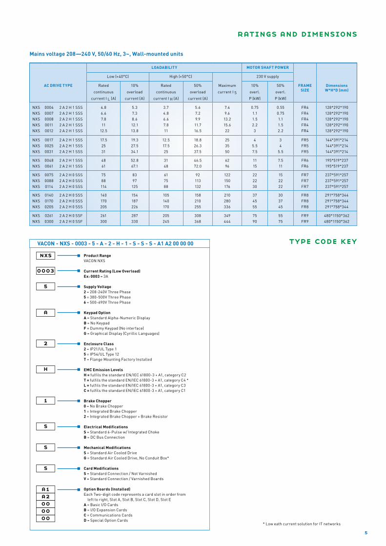
Mains voltage 208—240 V, 50/60 Hz, 3~, Wall-mounted units
nxs
0003
5
a
2
VACON - NXS - 0003 - 5 - A - 2 - H - 1 - S - S - S - A1 A2 00 00 00
Product RangeVACON NXS Current Rating (Low Overload) Ex: 0003 = 3A
Supply Voltage 2 = 208-240V Three Phase5 = 380-500V Three Phase 6 = 500-690V Three Phase
Keypad Option A = Standard Alpha-Numeric DisplayB = No KeypadF = Dummy Keypad (No interface)G = Graphical Display (Cyrillic Languages)
Enclosure Class 2 = IP21/UL Type 15 = IP54/UL Type 12 T = Flange Mounting Factory Installed
EMC Emission LevelsH = fulfils the standard EN/IEC 61800-3 + A1, category C2T = fulfils the standard EN/IEC 61800-3 + A1, category C4 *L = fulfils the standard EN/IEC 61800-3 + A1, category C3C = fulfils the standard EN/IEC 61800-3 + A1, category C1 Brake Chopper 0 = No Brake Chopper1 = Integrated Brake Chopper2 = Integrated Brake Chopper + Brake Resistor
Electrical ModificationsS = Standard 6-Pulse w/ Integrated ChokeB = DC Bus Connection Mechanical ModificationsS = Standard Air Cooled DriveG = Standard Air Cooled Drive, No Conduit Box* Card ModificationsS = Standard Connection / Not VarnishedV = Standard Connection / Varnished Boards
Option Boards (Installed)Each Two-digit code represents a card slot in order from
left to right, Slot A, Slot B, Slot C, Slot D, Slot EA = Basic I/O CardsB = I/O Expansion Cards C = Communications CardsD = Special Option Cards
h
1
s
s
s
a1a2000000
* Low eath current solution for IT networks

vacon option boards
6
vacon nxs control unit
There are no fixed inputs or outputs in the VACON NXS. There are five slots (A, B, C, D and E) for I/O boards, and a suitable board can be selected for each slot (see the table below).
The NXS units are delivered with OPT-A1 and OPT-A2 boards if the I/O is not specified. In many countries, boards OPT-A1 and OPT-A3 are used as standard I/O as the galvanically isolated thermistor input is often required.
Removable terminals, snap-in card installation, automatic card identification and instructions on the drive help making quick connections. If necessary, the inputs, outputs and fieldbus boards can be added in the field. The VACON NXS is simply the most flexible frequency converter series on the market.
An external +24 V supply option enables communication with the control unit even if the mains supply is switched off (e.g. fieldbus communication and parameter settings).
Card typecode Card slot I / O signal
A B C D E DI DO DIDO
AImA±V
AImAisol.
AOmA
V
AOmAisol.
RONONC
RONO
+10Vref
Therm +24EXT+24V
Pt100 42-240VAC
inputNOTE
Basic I/O cards (OPT-A)
OPT-A1 6 1 2 1 1 2
OPT-A2 2
OPT-A3 1 1 1
OPT-A8 6 1 2 1 1 2 1)
OPT-A9 6 1 2 1 1 2 2,5 mm2 terminals
I/O expander cards (OPT-B)
OPT-B1 6 1 Selectable DI/DO
OPT-B2 1 1 1
OPT-B4 1 2 1 2)
OPT-B5 3
OPT-B8 1 3
OPT-B9 1 5
Fieldbus cards (OPT-C)
OPT-C2 RS-485 (Multiprotocol) Modbus, N2
OPT-C3 Profibus DP
OPT-C4 LonWorks
OPT-C5 Profibus DP (D9 type connector)
OPT-C6 CANopen (slave)
OPT-C7 DeviceNet
OPT-C8 RS-485 (Multiprotocol, D9 type connector) Modbus, N2
OPT-CI Modbus/TCP
OPT-CJ BACNet
OPT-CP ProfiNet I/O (Ethernet)
OPT-CQ Ethernet I/P (Ethernet)
NOTES: Allowed slots for the board are marked in blue.
1) analogue signals galvanically isolated as a group, 2) analogue signals galvanically isolated separately.

7
vacon nxs standard i/o
OPT-A2
Terminal Defaults settings Programmable
21 R01
22 R01 RUN Many possibilities
23 R01
24 R02
25 R02 FAULT Many possibilities
26 R02
+24 V GND
230 VAC
N
OPT-A1
Terminal Defaults settings Programmable
1 +10V Reference voltage
2 AI1+ Frequency reference 0–10 V -10–+10 V, 0/4–20 mA
3 AI1- AI common (GND) Differential
4 AI2+ Frequency reference 4–20 mA 0–20mA, 0/-10 V–10 V
5 AI2- AI common (differential) GND
6 +24V Control supply (bidirectional)
7 GND I/O Ground
8 DIN1 Start forward Many possibilities
9 DIN2 Start reverse Many possibilities
10 DIN3 External fault input Many possibilities
11 CMA Common for DIN1 - DIN3 (GND) Floating
12 +24V Control supply (bidirectional)
13 GND I/O Ground
14 DIN4 Multi-step speed select 1 Many possibilities
15 DIN5 Multi-step speed select 2 Many possibilities
16 DIN6 Fault reset Many possibilities
17 CMB Common for DIN4 - DIN6 (GND) Floating
18 AO1+ Output frequency (0–20 mA) Many possibilities
19 AO1- AO common (GND) 4–20 mA, 0–10 V
20 DO1 READY, I < 50 mA, U < 48 VDC Many possibilities
1...10 kΩ
mA
OPT-A3 (alternative)
Terminal Defaults settings Programmable
21 R01
22 R01 RUN Many possibilities
23 R01
25 R02 FAULT Many possibilities
26 R02
28 TI1+ Thermistor
input fault
Warning, fault,
no response29 TI1-
+24 V GND
230 VAC
N
PTC
other typical options
OPTION ORDER TYPECODE AVAILABILITY NOTE
IP54 enclosure Factory option All Replace ‘2’ by ‘5’ in the type code, e.g. NXS02605A5H0 (SSS...)
IP5-FR_ FR4, FR5, FR6 IP54 kit, e.g. IP5-FR4
Through-hole mounting Factory option FR4-FR9 E.g. NXS02605ATH0STS..., IP54 back, IP21 front, kits available
Integrated brake choppers Standard FR4-6/230, 500 V E.g. NXS00455A2H1 (SSS...)
Factory option FR7- / 230 V, 500 VFR6- / 690 V
E.g. NXS02605A2H1 (SSS...)
External brake resistors BRR-0022-LD-5 00035-00225 LD = Light duty: 5 sec nominal torque braking fromnominal speed decreasing linearily to zero, once per 120 sec.HD = Heavy duty: 3 sec nominal torque braking atnominal speed + 7 sec nominal torque braking from nominalspeed decreasing linearily to zero, once per 120 sec. Replace LD by HD in the type code, e.g. BRR-0105-HD-5Brake resistors are also available for 208-240 V and 500-690 V NXS drivesThe brake resistor manual is available for more precise selection
(380 - 500 V range) BRR-0031-LD-5 00315
BRR-0045-LD-5 00385-00455
BRR-0061-LD-5 00615
BRR-0105-LD-5 00725-01055
BRR-0300-LD-5 01405-03005
Integrated brake resistors Factory option FR4-6/500 V Replace ‘1’ by ‘2’ in the typecode, e.g. NXS00455A2H2 (SSS...)Light duty: 2 sec nominal torque braking fromnominal speed decreasing linearily to zero, once per 60 sec.
Graphical display panel Factory option All Replace ‘A’ by ‘G’, e.g. NXS00455G2H1 (SSS..), supports Chinese & Russian
PAN-G All Order typecode when ordered separately
Panel door installation sets DRA-02B (-04B, -15B) All Length of RS232C cable is specified in the typecode, e.g. DRA-02B includes 2-meter RS232C cable
Varnished circuit boards Factory option All Frame sizes FR4-FR8: replace the ‘S’ by ‘V’, e.g.NXS00455A2H1SSV..., frame size FR9-FR11: replace ‘S’ by ‘G’
C-level RFI filters Factory option FR4-6/500 V Replace ‘H’ by ‘C’ in the typecode, e.g. NXS00455A5C1 (SSS..)
Du/dt & sinus filters Available for all drives, contact local Vacon supplier
Default settings of OPT-A1, OPT-A2 and OPT-A3 for the Basic and Standard Applications.

8
Basic
I/O Defaults
AI1 fref P
AI2 fref P
DI1 Start forward
DI2 Start reverse
DI3 External fault P
DI4 Speed select 1
DI5 Speed select 2
DI6 Fault reset
AO1 fout P
DO1 Ready
RO1 Run
RO2 Fault
Suitable for most purposes
Standard
I/O Defaults
AI1 fref P
AI2 fref P
DI1 Start forward P
DI2 Start reverse P
DI3 External fault P
DI4 Speed select 1
DI5 Speed select 2
DI6 Fault reset
AO1 fout P
DO1 Ready P
RO1 Run P
RO2 Fault P
Basic, with moreprogramming possibilities
Local/RemoteI/O Defaults
AI1 B fref P
AI2 A fref P
DI1 A Start forward P
DI2 A Start reverse P
DI3 External fault P
DI4 B Start forward P
DI5 B Start reverse P
DI6 A/B selection
AO1 fout P
DO1 Ready P
RO1 Run P
RO2 Fault P
Two external control places
Multi-step Speed Control
I/O Defaults
AI1 fref P
AI2 fref P
DI1 Start forward P
DI2 Start reverse P
DI3 External fault P
DI4 Speed select 1
DI5 Speed select 2
DI6 Speed select 3
AO1 fout P
DO1 Ready P
RO1 Run P
RO2 Fault P
16 fixed speeds
A maximum of three values can be monitored simultaneously (the multi-monitoring feature).
The uncluttered text display panel with a well-defined menu structure and functions such as automatic parameter copy and start-up wizard makes commissioning and fine-tuning as easy as possible.
• VACON NCDrive for parameter setting, copying, storing, printing, monitoring and controlling
• VACON NCLoad for software updating and uploading special software to the drive
• VACON® Programming tool is available for making tailor-made software. A license key and training required.
• The VACON PC tools require only an RS232C cable for communication with the drive (no adapters etc. required).
first-class usability
VACON® PC tools are available for download through our website at www.vacon.com.
vacon pc tools include

9
Multi-purpose Control
I/O Defaults
AI1 fref P
AI2 fref P
DI1 Start forward P
DI2 Start reverse P
DI3 Fault reset P
DI4 Jog speed sel P
DI5 External fault P
DI6 Acc/dec time sel P
AO1 fout P
DO1 Ready P
RO1 Run P
RO2 Fault P
Most flexible of all
Pump and Fan Control
I/O Defaults
AI1 PID reference P
AI2 PID actual value P
DI1 PID start/stop P
DI2 Interlock 1 P
DI3 Interlock 2 P
DI4 f ctrl start/stop P
DI5 Jog speed select P
DI6 PID/f ctrl select P
AO1 fout P
DO1 Fault P
RO1 Autochange 1 P
RO2 Autochange 2 P
The All-in-One application package has seven applications (=default settings and functionality of control inputs and outputs, see tables below) which can be selected with one parameter. The application will also be requested by the Start-up Wizard at the first power-up. With this single setting, the controls can be programmed e.g. for two external control places or a pressure control with the integrated PID controller. In most cases, the default basic application is suitable and only the min/max frequencies as well as motor nominal values must be set.
Thanks to the modular software applications made by the VACON Programming tool (based on IEC 61131 standard), the All-in-One application package can be replaced by the Water application package that contains several applications optimized for water handling. There are also several other general-purpose software applications available.
PID Control
I/O Defaults
AI1 PID reference P
AI2 PID actual value P
DI1 PID start/stop
DI2 External fault P
DI3 Fault reset P
DI4 f ctrl start/stop
DI5 Jog speed select P
DI6 PID/f ctrl select
AO1 fout P
DO1 Ready P
RO1 Run P
RO2 Fault P
When PID is required
Local /Remote
Multi-stepSpeed
Standard
PIDControl
Basic
Pump andFan Control
Multi-purpose
All-in-one Application package (standard)
Water Solutions application package (option)
Special Applications (several options)
P = Programmable
Multi-master
PFC
Advanced Level Control
MultiFollower PFC
Standard Lift
Fire mode PID
software modularity
Control of up to five pumpswith auto-change

1010
VACON NXS EMC Hospital Residential Area Commercial Light Industry Area Heavy Industry Marine
C O
H R R R O O
L R R
T R (IT Network) R (IT Network)
R = Required ; O = Optional
The product family standard EN/IEC 61800-3 + A1 sets limits for both emissions and immunity of radio frequency disturbances. The environment has been divided into the 1st and 2nd environments, i.e. in practice, the public and industrial networks, respectively.
Radio Frequency Interference (RFI) filters are typically required to meet the EN/IEC 61800-3 + A1 standard. These filters are integrated in the VACON NXS as standard.
The 208–240 V and 380–500 V ranges of the VACON NXS (FR4-FR9) fulfills the requirements of the 1st and 2nd environments (H level:
EN/IEC 61800-3 + A1, category C2). No additional RFI filters or cabinets are required. The FR10-FR11 and the 500-690 V range of the VACON NXS fulfills the requirements of the 2nd
environment (L-level: EN/IEC 61800-3 + A1, category C3).
The units in the frame sizes of FR4, FR5 and FR6 (the voltage range from 380 to 500 V) are also available with extremely low-emission integrated EMC filters (C level: EN/IEC 61800-3 + A1, category C1). This is sometimes required in very sensitive locations such as hospitals.
emc and installation environment
EMC Selection Table, restricted distribution
2ND ENVIRONMENT
1ST ENVIRONMENT
1
1
2
2
2
3
3
4
4
5
5

11
Mainsconnection
Input voltage Uin 208…240 V; 380…500 V; 500-690 V; (–10%…+10%)
Input frequency 50…60 Hz (± 10%)
Connection to mains Once per minute or less (normal case)
Motorconnection
Output voltage 0—Uin
Continuous output current High overloadability: IH
Low overloadability: ILOverloadability High: 1.5 x IH (1 min/10 min), Low: 1.1 x IL (1 min/10 min)
Max. starting current Is for 2 s every 20 s
Output frequency 0…320 Hz
Frequency resolution 0.01 Hz
Controlcharacteristics
Control method Frequency control U/f; Open Loop Vector Control (speed, torque)
Switching frequency 208..240V/380..500V: FR4-6: 1…16 kHz; Factory default: 10 kHz FR7-9: 1…6 kHz; Factory default: 3.6 kHz FR10-11: 1…6 kHz; Factory default: 3.6 kHz 500-690 V: FR4-11: 1…6 kHz, Factory default: 1.5 kHz
Field weakening point 8…320 Hz
Acceleration time 0.1…3000 sec
Deceleration time 0.1…3000 sec
Braking DC brake: 30% * TN (without brake resistor), flux braking
Ambient conditions
Ambient operating temperature –10°C (no frost)…+50°C: IH (FR10-FR11: max +40°C)–10°C (no frost)…+40°C: IL (NXS 0520 5, NXS 0416 6 and NXS 0590 6: max +35C)
Storage temperature –40°C…+70°C
Relative humidity 0 to 95% RH, non-condensing, non-corrosive, no dripping water
Air quality:- chemical vapours- mechanical particles
IEC 60721-3-3, unit in operation, class 3C2IEC 60721-3-3, unit in operation, class 3S2
Altitude 100% load capacity (no derating) up to 1000 m1-% derating for each 100 m above 1000 m; max. 3000 m (max. 2000 m for 690 V)
VibrationEN/IEC 60068-2-6
5...150 Hz: Displacement amplitude 1 mm (peak) at 5…15.8 Hz(FR10-FR11: 0,25 mm (peak) at 5…31 Hz)Max acceleration amplitude 1 G at 15.8…150 Hz (FR10 and up: 1 G at 31…150 Hz)
ShockEN/IEC 60068-2-27
UPS Drop Test (for applicable UPS weights)Storage and shipping: max 15 G, 11 ms (in package)
Enclosure class IP21 and IP54
EMC Immunity Fulfil all EMC immunity requirements
Emissions EMC level C: EN/IEC 61800-3 + A1, category C1EMC level H: EN/IEC 61800-3, + A1 category C2EMC level L: EN/IEC 61800-3, + A1 category C3EMC level T: Low earth-current solution suitable for IT networks, EN61800-3 + A1, category C4
Safety EN/IEC 61800-5-1, CE, UL, cUL; (see unit nameplate for more detailed approvals)
Controlconnections(OPT-A1, -A2 or OPT-A1, -A3)
Analogue input voltage 0…+10 V (–10 V…+10 V joystick control), Ri = 200 kΩ, resolution 0.1%, accuracy ±1%
Analogue input current 0(4)…20 mA, Ri = 250 Ω differential, resolution 0.1%, accuracy ±1%
Digital inputs 6, positive or negative logic; 18…30 VDC
Auxiliary voltage +24 V, ±10%, max. 250 mA
Output reference voltage +10 V, +3%, max. load 10 mA
Analogue output 0(4)…20 mA; RL max. 500 Ω, resolution 10 bit, accuracy ±2%
Digital output Open collector output, 50 mA/48 V
Relay outputs 2 programmable change-over (NO/NC) relay outputs (OPT-A3: NO/NC+NO)Switching capacity: 24 VDC/8 A, 250 VAC/8 A, 125 VDC/0.4 A. Min. switching load: 5 V/10 mA
Thermistor input (OPT-A3) Galvanically isolated, Rtrip = 4.7 kΩ
Protections Overvoltage, undervoltage, earth fault, mains supervision, motor phase supervision, overcurrent, unit overtemperature, motor overload, motor stall, motor underload, short-circuit of +24 V and +10 Vreference voltages
technical data

vacon at your service
vacon - truly global
Vacon is driven by a passion to develop, manufacture and sell the best AC drives and inverters in the world — and to provide customers with efficient product life-cycle services. Our AC drives offer optimum process control and energy efficiency for electric motors. Vacon inverters play a key role when energy is produced from renewable sources. Vacon has production and R&D facilities in Europe, Asia and North America, and sales and service operations in nearly 90 countries.
Production and R&D Vacon PLC Vacon own sales offices Served by Vacon partner
Vacon partner
Subject to changes without prior notice. VACON® is a registered trademark of Vacon Plc. www.vacon.com
BC00
146G
manufacturingand R&D on 3 continents
vacon sales and servicein more than 30 countries
sales and service partnersin 90 countries