Raster Etching on Goldfinger. Vector vs Raster G-Code works in Vector mode – laser is directed...
11
Raster Etching on Goldfinger
-
Upload
tracey-park -
Category
Documents
-
view
226 -
download
0
Transcript of Raster Etching on Goldfinger. Vector vs Raster G-Code works in Vector mode – laser is directed...

Raster Etchingon
Goldfinger
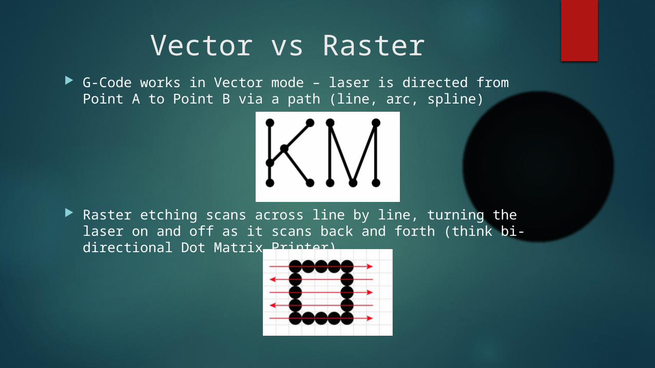
Vector vs Raster G-Code works in Vector mode – laser is directed from Point A to
Point B via a path (line, arc, spline)
Raster etching scans across line by line, turning the laser on and off as it scans back and forth (think bi-directional Dot Matrix Printer)
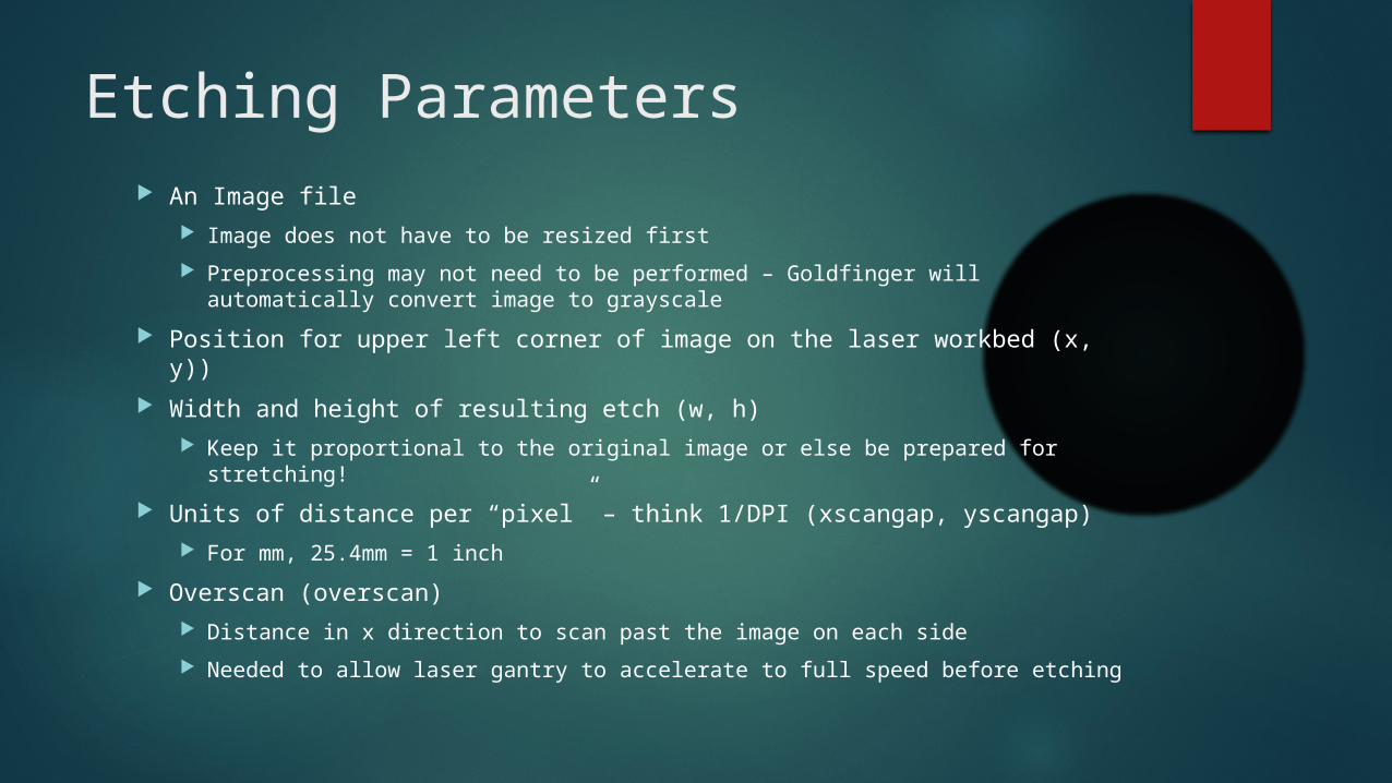
Etching Parameters An Image file
Image does not have to be resized first
Preprocessing may not need to be performed – Goldfinger will automatically convert image to grayscale
Position for upper left corner of image on the laser workbed (x, y))
Width and height of resulting etch (w, h) Keep it proportional to the original image or else be prepared for
stretching!
Units of distance per “pixel” – think 1/DPI (xscangap, yscangap) For mm, 25.4mm = 1 inch
Overscan (overscan) Distance in x direction to scan past the image on each side
Needed to allow laser gantry to accelerate to full speed before etching

w
Etching Parameters Visualized
h
x,y
Overscan(exaggerated)
Overscan(exaggerated)

Magic G-Code
Raster function is called by calling the O145 script from a G-Code file Script was written for Buildlog 2.x laser cutter
Uses Python Image Library for image processing and ties into LinuxCNC HAL
Script moves to (x-overscan,y) location and scans back and forth while taking input from image file on when to turn laser off and on
O145 call [777] [8] [190] [100] [182] [0.085] [0.423] [8]
( pic x y w h xscangap yscangap overscan )
Parameter sanity Image x position must be >= the overscan value
Image y position must be >= the image height
Increasing the pixel density in y-axis (decreasing yscangap) == more lines to scan == longer to etch the image
Increasing the pixel density in x-axis (decreasing xscangap) does not impact scan time
Overscan of 8mm appears to work well Lower values may work as well, I have not experimented yet to see how low we can go
Too low and the edges of the image will be darker than the middle due to the laser spending more time there
Higher values of course add time so finding the minimum acceptable value will be useful
DPI to scangap (for mm mode) == 25.4/DPI 300 DPI == 25.4/300 == 0.085
60 DPI == 25.4/60 == 0.423
Misc Notes I have so far only attempted plywood using PWM = 0.16 and
Feedrate of 3000mm/min with good results
Other materials will need adjustments to the power level and possibly the feedrate I would first try to adjust just power level as slower feedrates may
drastically increase etching time
Raster etching function is useable within a vector cutting G-Code file as well but parameters like M63/M65/Spindle Speed need to be controlled before and after the raster function Alternately, a vector file can be sent to the cutter after the raster file
(prior to moving the work piece)
Lower resolution needs more power

Entire G-Code File
%
M63 P0 (Turn off synchronized motion)
M65 P0 (Turn off digital output immediately)
G00 Z0.000001 (Z-Magic output off)
G21 (All units in mm)
M68 E0 Q0.16 (Set the laser to fire at 0.16)
F3000 (Feedrate 3000 mm/minute)
M3 (Enable the spindle – Laser can fire)
S0.000001 (Set the spindle to the slowest rate that LinuxCNC sees as being on)
O145 call [777] [8] [190] [100] [182] [0.085] [0.423] [8]
( pic x y w h xscangap yscangap overscan )
M5 (Disable the spindle – Laser cannot fire)
%

The easy way
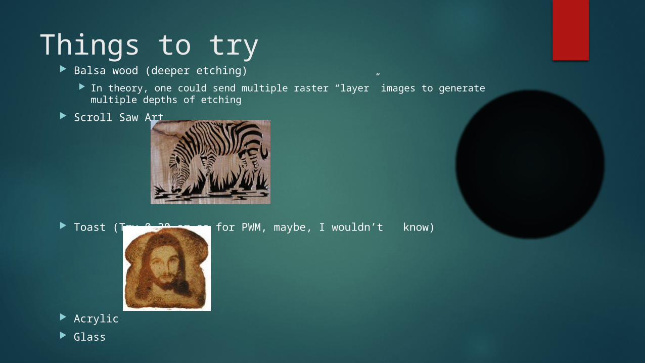
Things to try Balsa wood (deeper etching)
In theory, one could send multiple raster “layer” images to generate multiple depths of etching
Scroll Saw Art
Toast (Try 0.20 or so for PWM, maybe, I wouldn’t know)
Acrylic
Glass
Resources / References
https://knoxmakers.org/wiki/Raster_Engraving
http://goldfinger.kmlan/raster.php
https://www.youtube.com/watch?v=WEVeHWpXeF4
http://www.artifacturestudios.com/how-to-understand-the-difference-between-raster-and-vector-graphics/