RAS - Carrier
136
Form 513 56 3222 02 Rev. B 10-21 ELECTRIC COOLING, R-410A SINGLE PACKAGE ROOFTOP 6 - 15 TONS (3-PHASE) BUILT TO LAST, EASY TO INSTALL and SERVICE • Single-stage cooling capacity control on 072 models • Two-stage/two circuit cooling capacity control on 090-180 models • Two-stage/single circuit cooling capacity control on 089, 100, 119 models • Rated in accordance with AHRI Standard 340/360 • EERs up to 11.3 • IEERs up to 12.9 with single speed indoor fan motor • IEERs up to 13.0 with 2-speed/VFD indoor fan motor • Designed in accordance with Underwriters’ Laboratories Standard 1995 • Listed by UL and UL, Canada or ETL and ETL, Canada • Exclusive non-corrosive composite condensate pan in accordance with ASHRAE 62 Standard, sloping design; side or center drain • Pre-painted exterior panels and primer-coated interior panels tested to 500 hours salt spray protection • Fixed refrigerant metering system • Fully insulated cabinet • Cooling operating range from 40°F up to 115°F • Access panels with easy grip handles and no-strip screw feature • Two-inch disposable return air filters • Tool-less filter access door • Standard belt drive, constant torque motor • Advanced terminal board for simple safety circuit troubleshooting and control box arrangement • Field Convertible from vertical to horizontal airflow configuration on all models. No special kit required on 072-150 models. Field accessory supply duct kit required for 180 size models only. • Provisions for thru-the-bottom power entry capability • Single point electric connections • Full perimeter base rail with built-in rigging adapters and fork truck slots • Scroll compressors with internal line-break overload protection Copper tube, aluminum fin coils • 24-volt control circuit protected with resettable circuit breaker • Permanently lubricated evaporator-fan motor • Permanently lubricated, totally enclosed condenser-fan motors • Low pressure, freeze protection, and high-pressure switches • Liquid line filter drier standard FACTORY OPTIONS INCLUDING BUT NOT LIMITED TO: • Economizer and two position damper options • Disconnect and convenience outlet options • Multiple optional motor and pulley combinations • Corrosion resistant options for evaporator and condenser coils • 2 speed indoor fan motor on 2 stage cooling models • Integrated economizer system. Standard and Ultra Low Leak versions available WARRANTY • 5 Year limited warranty on compressor • 5 Year limited warranty on electric heater parts • 1 Year limited warranty on parts RAS Product Specifications ® RAS089-120 RAS180 RAS-072
Transcript of RAS - Carrier

Form 513 56 3222 02 Rev. B10-21
ELECTRIC COOLING, R-410A SINGLE PACKAGE ROOFTOP 6 - 15 TONS (3-PHASE)BUILT TO LAST, EASY TO INSTALL and SERVICE• Single-stage cooling capacity control on 072 models• Two-stage/two circuit cooling capacity control on 090-180 models• Two-stage/single circuit cooling capacity control on 089, 100, 119 models• Rated in accordance with AHRI Standard 340/360• EERs up to 11.3• IEERs up to 12.9 with single speed indoor fan motor• IEERs up to 13.0 with 2-speed/VFD indoor fan motor• Designed in accordance with Underwriters’ Laboratories Standard 1995• Listed by UL and UL, Canada or ETL and ETL, Canada• Exclusive non-corrosive composite condensate pan in accordance with ASHRAE 62
Standard, sloping design; side or center drain• Pre-painted exterior panels and primer-coated interior panels tested to 500 hours salt
spray protection• Fixed refrigerant metering system• Fully insulated cabinet• Cooling operating range from 40°F up to 115°F• Access panels with easy grip handles and no-strip screw feature• Two-inch disposable return air filters• Tool-less filter access door• Standard belt drive, constant torque motor• Advanced terminal board for simple safety circuit troubleshooting and control box
arrangement• Field Convertible from vertical to horizontal airflow configuration on all models. No
special kit required on 072-150 models. Field accessory supply duct kit required for 180size models only.
• Provisions for thru-the-bottom power entry capability• Single point electric connections• Full perimeter base rail with built-in rigging adapters and fork truck slots• Scroll compressors with internal line-break overload protection Copper tube, aluminum
fin coils• 24-volt control circuit protected with resettable circuit breaker• Permanently lubricated evaporator-fan motor• Permanently lubricated, totally enclosed condenser-fan motors• Low pressure, freeze protection, and high-pressure switches• Liquid line filter drier standard
FACTORY OPTIONS INCLUDING BUT NOT LIMITED TO:• Economizer and two position damper options• Disconnect and convenience outlet options• Multiple optional motor and pulley combinations• Corrosion resistant options for evaporator and condenser coils• 2 speed indoor fan motor on 2 stage cooling models• Integrated economizer system. Standard and Ultra Low Leak versions available
WARRANTY• 5 Year limited warranty on compressor• 5 Year limited warranty on electric heater parts• 1 Year limited warranty on parts
RASProduct Specifications
®
RAS089-120
RAS180
RAS-072

2 Specifications subject to change without notice. 513 56 3222 02 Rev. B
* Indicates Unit voltage: H = 208/230-3-60, L = 460-3-60, S = 575-3-60NOTE: BASE MODEL NUMBERS LISTED. SEE MODEL NOMENCLATURE LISTING FOR ADDITIONAL OPTIONS
UNIT PERFORMANCE DATA — Single Stage Cooling/Single Circuit
UNITCOOLING Unit Dimensions
H x W x LInches (mm)
UnitWeightlb. [kg]
NominalTons
Net. Cap (Btuh) EER Total Power
(kW)RAS072*0AA0AAA 6 70,000 11.2 6.4 41-3/8" x 46-3/4" x 74-3/8" (1051 x 1187 x 1888) 607 [275]
UNIT PERFORMANCE DATA — Two Stage Cooling/Single Circuit
UNITCOOLING Unit Dimensions
H x W x LInches (mm)
UnitWeightlb. [kg]
NominalTons
Net. Cap (Btuh) EER Total Power
(kW)RAS089*0AA0AAA 7-1/2 88,000 11.0 8.0 41-3/8" x 59-1/2" x 88-1/8" (1051 x 1510 x 2238) 705 [320]RAS100*0AA0AAA 8-1/2 97,000 11.2 8.8 49-3/8" x 59-1/2" x 88-1/8" (1253 x 1510 x 2238) 845 [384]RAS119*0AA0AAA 10 117,000 11.2 10.6 49-3/8" x 59-1/2" x 88-1/8" (1253 x 1510 x 2238) 855 [388]
UNIT PERFORMANCE DATA — Dual Stage Cooling/Two Circuits
UNITCOOLING Unit Dimensions
H x W x LInches (mm)
UnitWeightlb. [kg]
NominalTons
Net. Cap (Btuh) EER Total Power
(kW)RAS090*0AA0AAA 7-1/2 83,000 11.2 7.4 41-3/8" x 59-1/2" x 88-1/8" (1051 x 1510 x 2238) 760 [345]RAS102*0AA0AAA 8-1/2 97,000 11.2 9.0 49-3/8" x 59-1/2" x 88-1/8" (1253 x 1510 x 2238) 855 [388]RAS120*0AA0AAA 10 114,000 11.3 10.1 49-3/8" x 59-1/2" x 88-1/8" (1253 x 1510 x 2238) 865 [393]RAS150*0AA0AAA 12-1/2 140,000 11.0 12.7 49-3/8" x 59-1/2" x 88-1/8" (1253 x 1510 x 2238) 1075 [489]RAS180*0AA0AAA 15 174,000 11.0 15.8 57-3/8" x 63-3/8" x 115-7/8" (1456 x 1609 x 2942) 1305 [593]
TABLE OF CONTENTSPAGEMODEL NUMBER NOMENCLATURE . . . . . . . . . . . . . 3CAPACITY RATINGS . . . . . . . . . . . . . . . . . . . . . . . . . . 4PHYSICAL DATA. . . . . . . . . . . . . . . . . . . . . . . . . . . . . 21OPTIONS AND ACCESSORIES . . . . . . . . . . . . . . . . . 24DIMENSIONS . . . . . . . . . . . . . . . . . . . . . . . . . . . . . . . 35
PAGEAPPLICATION DATA. . . . . . . . . . . . . . . . . . . . . . . . . . 52PERFORMANCE DATA . . . . . . . . . . . . . . . . . . . . . . . 54ELECTRICAL DATA . . . . . . . . . . . . . . . . . . . . . . . . . . 65CONTROLS . . . . . . . . . . . . . . . . . . . . . . . . . . . . . . . 124GUIDE SPECIFICATIONS . . . . . . . . . . . . . . . . . . . . 127

513 56 3222 02 Rev. B Specifications subject to change without notice. 3
MODEL NUMBER NOMENCLATURE
1 Not available for RAS089 units.2 Combinations of FIOPS are available. Contact your sales representative for details.
MODEL SERIES R A S 0 9 0 H 0 A A 0 A A A
Position Number 1 2 3 4 5 6 7 8 9 10 11 12 13 14
R = Rooftop
A = Electric/Electric, Cooling Only Type
S = Standard DOE 2018/ASHRAE 90.1 - 2016 Efficiency
Nominal Cooling Capacity
089 = 7.5 Tons (1 circuit/two stage cooling)090 = 7.5 Tons (2 compressor/two stage cooling)100 = 8.5 Tons (1 circuit/two stage cooling)102 = 8.5 Tons (2 compressor/two stage cooling)119 = 10 Tons (1 circuit/two stage cooling)120 = 10 Tons (2 compressor/two stage cooling)150 = 12.5 Tons (2 compressor/two stage cooling)180 = 15 Tons (2 compressor/two stage cooling)
H = 208/230-3-60L = 460-3-60S = 575-3-60 Voltage
0 = No Heat Heating Capacity
A = Standard Motor/DriveB = High Static Motor/Drive1
C = Medium Static Motor/DriveE = High Static - High Efficiency Motor/DriveH = High Static Motor/Drive with Hot Gas Re-Heat (not available on 089, 100, 119 models)
Motor Option
A = NoneB = Low Leak Economizer w/Barometric relief, OA Temperature SensorE = Low Leak Economizer w/Barometric relief and CO2 Sensor, OA Temperature SensorH = Low Leak Economizer w/Barometric relief, Enthalpy SensorL = Low Leak Economizer w/Barometric relief and CO2 Sensor, Enthalpy SensorP = 2-Position Damper (non U.S. models only)U = Temperature Ultra Low Leak Economizer w/Barometric reliefW = Enthalpy Ultra Low Leak Economizer w/Barometric relief Outdoor Air Options
0A = Standard (no options)AT = Un-Powered Convenience Outlet4B = Non-Fused Disconnect SwitchBB = Powered Convenience OutletBR = Supply Air Smoke DetectorBP = Return Air Smoke DetectorAA = Easy Access Hinged Panels Factory Installed Options2
A = Aluminum/Copper Condenser and Evaporator CoilB = Precoat Alum/Cu Condenser and Alum/Cu EvaporatorC = E-Coated Alum/Cu Condenser and Alum/Cu EvaporatorD = E-Coated Alum/Cu Condenser and EvaporatorE = Cu/Cu Condenser and Alum/Cu EvaporatorF = Copper/Copper Condenser and Evaporator Standard Condenser / Evaporator Coil Configuration
A = Single-Speed Indoor Fan Motor, for W7212 controlsB = Single-Speed Indoor Fan Motor, for W7220 controlsT = Two-Speed Indoor Motor Controller (VFD) - Standard on U.S. models (except 089, 100, 119 models) Indoor Fan Motor
4 Specifications subject to change without notice. 513 56 3222 02 Rev. B
AHRI COOLING RATINGS
LEGEND
* Hi-Static Fan options for size 089 are not available.
NOTES:1. Rated and certified under AHRI Standard 340/360, as appropriate.2. Ratings are based on:
Cooling Standard: 80°F (27°C) db, 67°F (19°C) wb indoor. IEER Standard: A measure that expresses cooling part load EER efficiencyfor commercial unitary air conditioning and heat pump equipment on the basisof weighted operation at various load capacities.
3. The RAS090/102/120/150/180 units meet the DOE-2018 (Department ofEnergy), ASHRAE 90.1-2016 and IECC†-2015 minimum efficiency require-ments when equipped with the 2-speed indoor fan motor option.
4. The RAS089/100/119 rooftops meet the DOE-2018 minimum efficiencyrequirement without the 2-speed indoor fan motor option.
† IECC is a registered trademark of International Code Council, Inc.
SOUND RATING PERFORMANCE
LEGEND NOTES:1. Outdoor sound data is measure in accordance with AHRI standard 270.2. Measurements are expressed in terms of sound power. Do not compare
these values to sound pressure values because sound pressure depends onspecific environmental factors which normally do not match individual appli-cations. Sound power values are independent of the environment and there-fore more accurate.
3. A-weighted sound ratings filter out very high and very low frequencies, tobetter approximate the response of “average” human ear. A-weighted mea-surements for units are taken in accordance with AHRI standard 270.
RASUNIT
COOLING STAGES
REFRIGERANTCIRCUITS
NOM. CAPACITY
(TONS)
NET COOLING CAPACITY
(MBH)
TOTAL POWER
(kW) EER
IEER WITH SINGLE SPEED INDOOR FAN
MOTOR
IEER WITH 2-SPEED INDOOR
FAN MOTOR 072 1 1 6.0 70.0 6.4 11.2 11.4 12.9089* 2 1 7.5 88.0 8.0 11.0 12.9 N/A090 2 2 7.5 83.0 7.4 11.2 11.7 13.0100 2 1 8.5 97.0 8.8 11.2 12.9 N/A102 2 2 8.5 99.0 8.8 11.2 11.7 13.0119 2 1 10.0 117.0 10.4 11.2 12.9 N/A120 2 2 10.0 114.0 10.1 11.3 12.2 13.0150 2 2 12.5 140.0 12.7 11.0 11.2 12.4180 2 2 15.0 174.0 15.8 11.0 11.7 12.6
AHRI — Air-Conditioning, Heating and Refrigeration Institute Test StandardASHRAE — American Society of Heating, Refrigerating and Air-Conditioning
EngineersEER — Energy Efficiency RatioIEER — Integrated Energy Efficiency RatioIECC — International Energy Conservation CodeN/A — Not Applicable
®
RASUNIT
COOLING STAGES
OUTDOOR SOUND (dB) AT 60 HzA-Weighted 63 125 250 500 1000 2000 4000 8000
072 1 78 88.8 81.8 76.9 74.4 73.3 69.8 66.3 62.7089 2 82 90.1 82.6 81.0 79.4 77.0 73.0 70.4 66.7090 2 82 85.8 84.3 80.5 78.7 76.4 72.7 68.3 65.1100 2 83 91.2 86.4 81.9 81.0 78.3 73.9 71.4 67.3102 2 82 88.6 85.0 81.6 79.5 77.4 74.1 71.0 66.3119 2 82 88.6 85.0 81.6 79.5 77.4 74.1 71.0 66.3120 2 82 89.0 83.1 80.5 78.5 75.5 71.6 69.6 69.3150 2 87 87.0 85.2 84.6 84.9 82.2 78.4 75.3 72.9180 2 87 87.0 85.2 84.6 84.9 82.2 78.4 75.3 72.9
dB — Decibel
CAPACITY RATINGS

513 56 3222 02 Rev. B Specifications subject to change without notice. 5
MINIMUM - MAXIMUM AIRFLOW RATINGS - COOLING AND ELCTRIC HEAT
* Minimum electric heat CFM exceptions, see table below.
MINIMUM ELECTRIC HEAT CFM EXCEPTIONS
* Not available on RAS-089 units.
UNIT
COOLING ELECTRIC HEATERS
Minimum
Minimum 2-Speed Fan Motor
(at High Speed)
Minimum 2-Speed Fan Motor
(at Low Speed) Maximum Minimum MaximumRAS072 1800 N/A N/A 3000 1800 3000
RAS089/090 2250 2250 1500 3750 2250* 3750RAS100/102 2550 2873 1915 4250 2550* 4250RAS119/120 3000 3380 2253 5000 3000* 5000
RAS150 3600 4056 2704 6000 3000* 6000RAS180 4500 5625 3750 7500 4500 7500
UNIT UNIT VOLTAGE HEATER kW UNIT CONFIGURATION REQUIRED MINIMUM CFMRAS119/120
208/230 42.4 Horizontal 3200RAS150
RAS119/120208/230 50.0 Horizontal 3200
RAS150RAS089/090RAS100/102RAS119/120
RAS150575*
17.0Horizontal or Vertical
2800
34.0 2350
CAPACITY RATINGS (cont)

6 Specifications subject to change without notice. 513 56 3222 02 Rev. B
COOLING CAPACITIES — 1-CIRCUIT/1-STAGE COOLING, 6 TONS
LEGEND NOTE: See Minimum-Maximum Airflow Ratings table on page 5. Do not operateoutside these limits.
RAS072(RTPF)
AMBIENT TEMPERATURE (F)85 95 105 115
EAT (db) EAT (db) EAT (db) EAT (db)75 80 85 75 80 85 75 80 85 75 80 85
1800
Cfm
EAT
(wb)
58TC 64.9 64.9 73.3 62.1 62.1 70.0 58.9 58.9 66.4 55.6 55.6 62.7
SHC 56.6 64.9 73.3 54.1 62.1 70.0 51.4 58.9 66.4 48.5 55.6 62.7
62TC 68.7 68.7 70.3 64.9 64.9 68.5 60.8 60.8 66.4 56.4 56.4 64.0
SHC 51.7 61.0 70.3 49.9 59.2 68.5 47.9 57.2 66.4 45.7 54.9 64.0
67TC 75.6 75.6 75.6 71.7 71.7 71.7 67.4 67.4 67.4 62.5 62.5 62.5
SHC 42.8 52.2 61.5 41.2 50.5 59.8 39.3 48.6 58.0 37.2 46.5 55.8
72TC 82.6 82.6 82.6 78.5 78.5 78.5 73.7 73.7 73.7 67.8 67.8 67.8
SHC 33.5 42.8 52.2 31.9 41.3 50.6 30.0 39.3 48.6 27.8 36.9 45.9
76TC — 87.5 87.5 — 83.3 83.3 — 77.7 77.7 — 70.9 70.9
SHC — 35.0 44.9 — 33.5 43.4 — 31.6 41.5 — 29.3 39.1
2100
Cfm
EAT
(wb)
58TC 68.9 68.9 77.7 65.9 65.9 74.3 62.5 62.5 70.5 58.7 58.7 66.2
SHC 60.1 68.9 77.7 57.4 65.9 74.3 54.5 62.5 70.5 51.2 58.7 66.2
62TC 70.9 70.9 76.9 67.1 67.1 75.0 63.0 63.0 72.5 58.7 58.7 68.7
SHC 55.6 66.3 76.9 53.8 64.4 75.0 51.6 62.1 72.5 48.7 58.7 68.7
67TC 77.8 77.8 77.8 73.7 73.7 73.7 69.2 69.2 69.2 64.0 64.0 64.0
SHC 45.4 56.1 66.8 43.7 54.4 65.2 41.8 52.5 63.2 39.6 50.2 60.7
72TC 84.5 84.5 84.5 80.3 80.3 80.3 75.1 75.1 75.1 68.8 68.8 68.8
SHC 34.5 45.2 55.9 32.9 43.5 54.2 30.9 41.4 52.0 28.5 38.7 48.9
76TC — 89.2 89.2 — 84.7 84.7 — 78.8 78.8 — 71.6 71.6
SHC — 36.3 47.8 — 34.7 46.0 — 32.6 43.7 — 30.1 40.9
2400
Cfm
EAT
(wb)
58TC 72.0 72.0 81.2 68.7 68.7 77.5 65.2 65.2 73.5 61.1 61.1 68.9
SHC 62.8 72.0 81.2 60.0 68.7 77.5 56.9 65.2 73.5 53.3 61.1 68.9
62TC 72.8 72.8 82.8 68.9 68.9 80.7 65.2 65.2 76.4 61.2 61.2 71.6
SHC 59.1 71.0 82.8 57.2 68.9 80.7 54.1 65.2 76.4 50.7 61.2 71.6
67TC 79.4 79.4 79.4 75.2 75.2 75.2 70.5 70.5 70.5 65.1 65.1 65.3
SHC 47.7 59.8 71.8 46.0 58.1 70.2 44.0 56.0 68.1 41.6 53.5 65.3
72TC 86.0 86.0 86.0 81.6 81.6 81.6 76.1 76.1 76.1 69.6 69.6 69.6
SHC 35.3 47.2 59.2 33.7 45.6 57.5 31.7 43.3 55.0 29.1 40.3 51.4
76TC — 90.3 90.3 — 85.7 85.7 — 79.6 79.6 — 72.1 72.1
SHC — 37.3 49.8 — 35.6 48.0 — 33.5 45.6 — 30.8 42.5
2700
Cfm
EAT
(wb)
58TC 60.3 60.3 74.1 71.1 71.1 80.2 67.4 67.4 76.0 63.0 63.0 71.1
SHC 46.4 60.3 74.1 62.0 71.1 80.2 58.8 67.4 76.0 55.0 63.0 71.1
62TC 65.4 65.4 69.3 71.2 71.2 83.3 67.5 67.5 79.0 63.1 63.1 73.8
SHC 41.0 55.1 69.3 59.0 71.2 83.3 55.9 67.5 79.0 52.3 63.1 73.8
67TC 72.7 72.7 72.7 76.3 76.3 76.3 71.5 71.5 72.6 65.8 65.8 69.4
SHC 33.8 48.0 62.2 48.2 61.6 74.9 46.1 59.3 72.6 43.5 56.5 69.4
72TC 79.7 79.7 79.7 82.5 82.5 82.5 76.9 76.9 76.9 70.1 70.1 70.1
SHC 25.8 40.2 54.6 34.5 47.5 60.5 32.3 45.0 57.7 29.7 41.7 53.8
76TC — 85.1 85.1 — 86.4 86.4 — 80.2 80.2 — 72.5 72.5
SHC — 33.5 48.4 — 36.5 49.9 — 34.3 47.3 — 31.5 44.0
3000
Cfm
EAT
(wb)
58TC 64.9 64.9 78.8 73.1 73.1 82.5 69.2 69.2 78.0 64.5 64.5 72.7
SHC 51.1 64.9 78.8 63.8 73.1 82.5 60.3 69.2 78.0 56.2 64.5 72.7
62TC 68.7 68.7 76.5 73.2 73.2 85.7 69.2 69.2 81.0 64.5 64.5 75.5
SHC 45.5 61.0 76.5 60.7 73.2 85.7 57.4 69.2 81.0 53.5 64.5 75.5
67TC 75.6 75.6 75.6 77.2 77.2 79.4 72.2 72.2 76.8 66.3 66.3 73.0
SHC 36.6 52.2 67.7 50.2 64.8 79.4 48.0 62.4 76.8 45.1 59.1 73.0
72TC 82.6 82.6 82.6 83.3 83.3 83.3 77.5 77.5 77.5 70.5 70.5 70.5
SHC 27.2 42.8 58.5 35.1 49.2 63.3 32.9 46.6 60.3 30.2 43.0 55.9
76TC — 87.5 87.5 — 86.9 86.9 — 80.6 80.6 — 72.8 72.8
SHC — 35.0 51.5 — 37.3 51.6 — 35.0 48.9 — 32.1 45.3
— — Do not operateCfm — Cubic feet per minute (supply air)EAT (db) — Entering Air Temperature (dry bulb)EAT (wb) — Entering Air Temperature (wet bulb)SHC — Sensible Heat Capacity (1000 Btuh) GrossTC — Total Capacity (1000 Btuh) Gross
CAPACITY RATINGS (cont)
513 56 3222 02 Rev. B Specifications subject to change without notice. 7
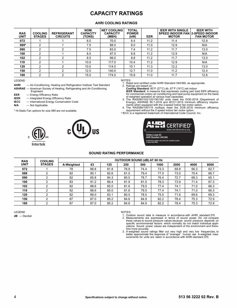
COOLING CAPACITIES — 1-CIRCUIT/1-STAGE COOLING, 6 TONS (cont)
LEGEND NOTES:1. Direct interpolation is permissible. Do not extrapolate.2. The following formulas may be used:
tlwb = Wet-bulb temperature corresponding to enthalpy of airleaving evaporator coil (hlwb)
Where: hewb = Enthalpy of air entering evaporator coil
6 TON UNIT WITH HOT GAS RE-HEAT SYSTEM IN SUBCOOLING MODE
Temp (F)Air Entering
Condenser (Edb)
Air Entering Evaporator - CFM4,500 6,000 7,500
Air Entering Evaporator - Ewb (F)72 67 62 72 67 62 72 67 62
75TC 208.50 190.60 172.60 229.20 208.60 188.10 247.80 224.90 202.00
SHC 94.00 114.50 135.00 104.50 125.20 145.90 113.00 133.80 154.60kW 13.42 13.05 12.70 13.60 13.21 12.80 13.82 13.36 13.15
85TC 198.30 180.70 163.00 214.90 194.80 174.60 229.80 207.40 185.10
SHC 74.10 99.60 125.10 85.20 110.90 136.70 94.10 120.00 145.90kW 14.79 14.42 14.10 14.97 14.58 14.20 15.19 14.73 14.51
95TC 188.20 170.80 153.40 200.60 180.90 161.10 211.90 190.00 168.10
SHC 54.40 84.80 115.30 65.90 96.70 127.50 75.10 106.20 137.20kW 16.23 15.86 15.50 16.41 16.02 15.60 16.63 16.17 15.95
105TC 178.10 160.90 143.80 186.40 167.00 147.70 193.90 172.50 151.20
SHC 34.60 70.00 105.40 46.50 82.40 118.20 56.10 92.30 128.50kW 17.47 17.10 16.80 17.65 17.26 16.90 17.87 17.41 17.25
115TC 167.90 151.10 134.20 172.10 153.20 134.20 175.90 155.10 134.50
SHC 14.80 55.20 95.60 27.20 68.10 109.00 37.10 78.50 119.80kW 18.87 18.50 18.20 19.05 18.66 18.30 19.27 18.81 18.55
6 TON UNIT WITH HOT GAS RE-HEAT SYSTEM IN HOT GAS REHEAT MODEAir Entering Evaporator – CFM
Temp (F)Air Entering
Condenser (Edb)
75 dry bulb 75 dry bulb 75 dry bulb62.5 wet bulb (50% relative) 64 wet bulb (55% relative) 65.3 wet bulb (60% relative)
2100 2400 2700 2100 2400 2700 1750 2000 2700
80TC 16.7 19.8 22.5 18.8 21.9 24.7 16.2 19.4 26.7
SHC 0.6 0.6 0.6 -0.4 -0.4 -0.4 -1.3 -1.3 -1.3kW 4.0 4.0 4.0 4.0 4.0 4.0 4.0 4.0 4.0
75TC 17.7 20.6 23.1 19.6 22.6 25.3 17.3 20.3 27.1
SHC 0.6 0.6 0.6 -0.3 -0.3 -0.3 -1.2 -1.2 -1.2kW 4.0 4.0 4.0 4.0 4.0 4.0 4.0 4.0 4.0
70TC 18.6 21.3 23.7 20.5 23.3 25.8 18.3 21.1 27.6
SHC 0.7 0.7 0.7 -0.2 -0.2 -0.2 -1.0 -1.0 -1.0kW 4.0 4.0 4.0 4.1 4.1 4.1 4.1 4.1 4.1
60TC 20.5 22.9 25.0 22.2 24.7 26.8 20.4 22.8 28.5
SHC 0.7 0.7 0.7 -0.0 -0.0 -0.0 -0.7 -0.7 -0.7kW 4.1 4.1 4.1 4.1 4.1 4.1 4.1 4.1 4.1
50TC 22.4 24.4 26.2 24.0 26.0 27.9 22.4 24.5 29.3
SHC 0.8 0.8 0.8 0.1 0.1 0.1 -0.4 -0.4 -0.4kW 4.1 4.1 4.1 4.1 4.1 4.1 4.2 4.2 4.2
40TC 24.3 25.9 27.4 25.7 27.4 28.9 24.5 26.3 30.2
SHC 0.8 0.8 0.8 0.3 0.3 0.3 -0.1 -0.1 -0.1kW 4.1 4.1 4.1 4.2 4.2 4.2 4.2 4.2 4.2
Edb — Entering Dry-BulbEwb — Entering Wet-BulbkW — Compressor Motor Power Inputldb — Leaving Dry-Bulblwb — Leaving Wet-BulbSHC — Sensible Heat Capacity (1000 Btuh) GrossTC — Total Capacity (1000 Btuh) Gross
tldb = tedb – sensible capacity (Btuh)1.10 x cfm
hlwb = hewb – total capacity (Btuh)4.5 x cfm
CAPACITY RATINGS (cont)

8 Specifications subject to change without notice. 513 56 3222 02 Rev. B
COOLING CAPACITIES — 2-CIRCUIT/2-STAGE COOLING, 7.5 TONS
LEGEND NOTE: See Minimum-Maximum Airflow Ratings table on page 5. Do not operateoutside these limits.
RAS090(RTPF)
AMBIENT TEMPERATURE (F)85 95 105 115
EAT (db) EAT (db) EAT (db) EAT (db)75 80 85 75 80 85 75 80 85 75 80 85
2250
Cfm
EAT
(wb)
58 TC 77.4 77.4 87.8 73.8 73.8 83.8 70.1 70.1 79.5 66.0 66.0 74.9SHC 66.9 77.4 87.8 63.9 73.8 83.8 60.6 70.1 79.5 57.1 66.0 74.9
62 TC 82.2 82.2 83.9 77.5 77.5 81.7 72.6 72.6 79.2 67.3 67.3 76.4SHC 60.8 72.4 83.9 58.6 70.1 81.7 56.3 67.7 79.2 53.6 65.0 76.4
67 TC 90.1 90.1 90.1 86.0 86.0 86.0 81.4 81.4 81.4 75.9 75.9 75.9SHC 50.2 61.8 73.3 48.5 60.1 71.6 46.5 58.1 69.7 44.2 55.8 67.4
72 TC 98.0 98.0 98.0 94.0 94.0 94.0 89.5 89.5 89.5 84.3 84.3 84.3SHC 39.1 50.7 62.4 37.5 49.2 60.9 35.8 47.5 59.2 33.8 45.5 57.2
76TC — 104.3 104.3 — 100.4 100.4 — 95.9 95.9 — 90.7 90.7
SHC — 41.7 54.0 — 40.3 52.7 — 38.7 51.0 — 36.8 49.0
2625
Cfm
EAT
(wb)
58 TC 82.1 82.1 93.2 78.4 78.4 89.0 74.4 74.4 84.4 70.0 70.0 79.5SHC 71.0 82.1 93.2 67.8 78.4 89.0 64.3 74.4 84.4 60.6 70.0 79.5
62 TC 84.9 84.9 91.8 80.4 80.4 89.5 75.4 75.4 86.7 70.2 70.2 82.9SHC 65.4 78.6 91.8 63.2 76.3 89.5 60.6 73.7 86.7 57.6 70.2 82.9
67 TC 92.5 92.5 92.5 88.3 88.3 88.3 83.6 83.6 83.6 78.3 78.3 78.3SHC 53.0 66.3 79.5 51.3 64.6 78.0 49.4 62.8 76.1 47.2 60.6 73.9
72 TC 100.4 100.4 100.4 96.4 96.4 96.4 91.7 91.7 91.7 86.4 86.4 86.4SHC 40.2 53.5 66.7 38.7 52.0 65.3 36.9 50.3 63.7 35.0 48.4 61.8
76TC — 106.5 106.5 — 102.6 102.6 — 98.0 98.0 — 92.7 92.7
SHC — 43.3 57.6 — 41.8 55.9 — 40.2 54.1 — 38.4 52.2
3000
Cfm
EAT
(wb)
58 TC 85.7 85.7 97.3 82.2 82.2 93.3 78.0 78.0 88.6 73.5 73.5 83.4SHC 74.1 85.7 97.3 71.1 82.2 93.3 67.5 78.0 88.6 63.6 73.5 83.4
62 TC 86.9 86.9 98.7 82.8 82.8 96.4 78.2 78.2 92.3 73.6 73.6 86.9SHC 69.3 84.0 98.7 67.2 81.8 96.4 64.1 78.2 92.3 60.3 73.6 86.9
67 TC 94.3 94.3 94.3 90.1 90.1 90.1 85.2 85.2 85.2 79.8 79.8 80.1SHC 55.6 70.5 85.4 54.0 68.9 83.9 52.1 67.1 82.2 49.9 65.0 80.1
72 TC 102.2 102.2 102.2 98.1 98.1 98.1 93.3 93.3 93.3 87.9 87.9 87.9SHC 41.2 56.0 70.7 39.7 54.6 69.5 38.0 53.0 68.0 36.0 51.1 66.2
76TC — 108.1 108.1 — 104.2 104.2 — 99.5 99.5 — 94.2 94.2
SHC — 44.5 60.2 — 43.2 58.7 — 41.6 57.0 — 39.8 55.2
3375
Cfm
EAT
(wb)
58 TC 88.5 88.5 100.4 85.0 85.0 96.4 81.0 81.0 92.0 76.5 76.5 86.8SHC 76.5 88.5 100.4 73.5 85.0 96.4 70.1 81.0 92.0 66.1 76.5 86.8
62 TC 88.9 88.9 103.9 85.1 85.1 100.4 81.1 81.1 95.7 76.5 76.5 90.3SHC 72.3 88.1 103.9 69.7 85.1 100.4 66.5 81.1 95.7 62.7 76.5 90.3
67 TC 95.8 95.8 95.8 91.5 91.5 91.5 86.6 86.6 87.9 81.1 81.1 85.8SHC 58.0 74.4 90.9 56.4 73.0 89.6 54.6 71.3 87.9 52.4 69.1 85.8
72 TC 103.6 103.6 103.6 99.4 99.4 99.4 94.6 94.6 94.6 89.1 89.1 89.1SHC 42.0 58.3 74.5 40.6 57.0 73.4 38.9 55.5 72.0 37.0 53.7 70.3
76TC — 109.2 109.2 — 105.4 105.4 — 100.7 100.7 — 95.3 95.3
SHC — 45.6 62.6 — 44.4 61.3 — 42.8 59.7 — 41.0 58.0
3750
Cfm
EAT
(wb)
58 TC 90.8 90.8 103.0 87.3 87.3 99.1 83.3 83.3 94.5 78.8 78.8 89.4SHC 78.5 90.8 103.0 75.5 87.3 99.1 72.0 83.3 94.5 68.2 78.8 89.4
62 TC 90.9 90.9 107.2 87.4 87.4 103.1 83.3 83.3 98.4 78.9 78.9 93.1SHC 74.5 90.9 107.2 71.6 87.4 103.1 68.3 83.3 98.4 64.7 78.9 93.1
67 TC 97.0 97.0 97.0 92.6 92.6 95.1 87.6 87.6 93.4 82.1 82.1 91.2SHC 60.3 78.2 96.2 58.8 76.9 95.1 56.9 75.2 93.4 54.8 73.0 91.2
72 TC 104.7 104.7 104.7 100.5 100.5 100.5 95.6 95.6 95.6 90.1 90.1 90.1SHC 42.9 60.5 78.1 41.4 59.3 77.1 39.8 57.8 75.9 37.9 56.1 74.3
76TC — 110.2 110.2 — 106.2 106.2 — 101.6 101.6 — 96.1 96.1
SHC — 46.7 64.8 — 45.4 63.6 — 44.0 62.3 — 42.2 60.6
— — Do not operateCfm — Cubic feet per minute (supply air)EAT (db) — Entering Air Temperature (dry bulb)EAT (wb) — Entering Air Temperature (wet bulb)SHC — Sensible Heat Capacity (1000 Btuh) GrossTC — Total Capacity (1000 Btuh) Gross
CAPACITY RATINGS (cont)

513 56 3222 02 Rev. B Specifications subject to change without notice. 9
COOLING CAPACITIES — 2-CIRCUIT/2-STAGE COOLING, 7.5 TONS (cont)
LEGEND NOTES:1. Direct interpolation is permissible. Do not extrapolate.2. The following formulas may be used:
tlwb = Wet-bulb temperature corresponding to enthalpy of airleaving evaporator coil (hlwb)
Where: hewb = Enthalpy of air entering evaporator coil
7.5 TON COOLING CAPACITIES, RTPF UNIT WITH HOT GAS RE-HEAT SYSTEM IN SUBCOOLING MODE
Temp (F)Air Entering
Condenser (Edb)
AIR ENTERING EVAPORATOR - CFM2250/0.05 3000/0.07 3750/0.09
Air Entering Evaporator - Ewb (F)72 67 62 72 67 62 72 67 62
75TC 103.05 93.02 83.60 109.77 99.52 90.08 114.01 103.69 95.19
SHC 43.66 55.34 67.09 50.99 66.29 81.31 57.49 76.27 92.20kW 4.90 4.83 4.77 4.82 4.88 4.96 4.99 4.91 4.85
85TC 95.39 85.83 76.88 101.59 91.89 82.95 105.53 95.76 87.77
SHC 36.42 48.47 60.60 43.24 58.99 74.40 49.44 68.68 84.90kW 5.49 5.42 5.36 5.40 5.47 5.54 5.58 5.50 5.44
95TC 87.48 78.44 69.97 93.21 84.05 75.61 96.84 87.63 80.14
SHC 28.98 41.46 53.97 35.32 51.53 67.34 41.21 60.92 77.41kW 6.16 6.09 6.03 6.08 6.14 6.21 6.24 6.17 6.11
105TC 79.35 70.83 62.84 84.57 75.96 68.04 87.88 79.23 72.26
SHC 21.34 34.26 47.18 27.17 43.86 60.08 32.73 52.95 69.70kW 6.93 6.86 6.81 6.85 6.91 6.97 7.00 6.93 6.88
115TC 70.87 62.89 55.42 75.58 67.54 60.15 78.56 70.51 64.06
SHC 13.40 26.79 40.14 18.70 35.89 52.54 23.94 44.68 61.67kW 7.79 7.74 7.69 7.73 7.78 7.83 7.86 7.80 7.76
7.5 TON COOLING CAPACITIES, RTPF UNIT WITH HOT GAS REHEAT IN HOT GAS REHEAT MODE
Temp (F)Air Entering
Condenser (Edb)
Air Entering Evaporator - Ewb (F)75 Dry Bulb 75 Dry Bulb 75 Dry Bulb
62.5 Wet Bulb 64 Wet Bulb 65.3 Wet Bulb(50% Relative) (56% Relative) (60% Relative)
Air Entering Evaporator - CFM2250 3000 3750 2250 3000 3750 2250 3000 3750
80TC 27.60 32.75 30.19 40.09 39.43 37.73 45.06 45.25 44.25
SHC -3.12 5.20 6.71 3.75 5.24 6.75 3.77 5.26 6.78kW 4.56 4.51 4.46 4.63 4.60 4.56 4.70 4.67 4.64
75TC 35.40 33.78 31.20 41.14 40.51 38.80 46.15 46.37 45.38
SHC 4.67 6.17 7.69 4.71 6.21 7.73 4.74 6.24 7.76kW 4.41 4.36 4.39 4.41 4.36 4.36 4.41 4.39 4.36
70TC 36.36 34.71 32.18 42.10 41.47 39.77 47.08 47.31 46.32
SHC 5.63 7.14 8.66 5.67 7.18 8.71 5.70 7.21 8.74kW 4.43 4.49 4.41 4.44 4.40 4.39 4.49 4.47 4.44
60TC 38.25 36.64 34.15 43.97 43.37 41.72 48.98 49.22 48.26
SHC 7.56 9.09 10.62 7.60 9.13 10.66 7.62 9.15 10.69kW 4.56 4.55 4.43 4.57 4.53 4.46 4.56 4.55 4.50
50TC 40.15 38.60 36.14 45.95 45.37 43.73 50.57 50.97 49.56
SHC 9.48 11.03 12.58 9.52 11.07 12.62 9.54 11.10 12.64kW 4.63 4.52 4.38 4.45 4.41 4.33 5.25 4.91 5.60
40TC 42.18 40.62 38.11 47.80 47.25 45.43 52.65 52.75 51.83
SHC 11.41 12.98 14.54 11.45 13.02 14.58 11.47 13.04 14.60kW 4.32 4.37 4.37 4.65 4.60 4.89 4.96 5.20 5.12
Edb — Entering Dry-BulbEwb — Entering Wet-BulbkW — Compressor Motor Power Inputldb — Leaving Dry-Bulblwb — Leaving Wet-BulbSHC — Sensible Heat Capacity (1000 Btuh) GrossTC — Total Capacity (1000 Btuh) Gross
tldb = tedb -sensible capacity (Btuh)
1.10 x cfm
hlwb = hewb -total capacity (Btuh)
4.5 x cfm
CAPACITY RATINGS (cont)

10 Specifications subject to change without notice. 513 56 3222 02 Rev. B
COOLING CAPACITIES — 1-CIRCUIT 2-STAGE COOLING, 7.5 TONS
LEGEND * Not available in 575V models or 208/230/3/60 and 460/3/60 models with highstatic indoor fan motor.
NOTE: See Minimum-Maximum Airflow Ratings table on page 5. Do not operateoutside these limits.
RAS089*(RTPF)
AMBIENT TEMPERATURE (F)85 95 105 115
EAT (db) EAT (db) EAT (db) EAT (db)75 80 85 75 80 85 75 80 85 75 80 85
2250
Cfm
EAT
(wb)
58 TC 79.6 79.6 87.7 76.2 76.2 86.4 73.1 73.1 82.8 69.5 69.5 78.8SHC 67.5 77.6 87.7 66.0 76.2 86.4 63.2 73.0 82.8 60.2 69.5 78.8
62 TC 85.6 85.6 85.6 81.6 81.6 81.6 77.3 77.3 78.5 72.6 72.6 76.4SHC 60.8 71.5 82.1 59.0 69.7 80.4 57.0 67.8 78.5 54.9 65.7 76.4
67 TC 94.5 94.5 94.5 90.0 90.0 90.0 85.2 85.2 85.2 80.0 80.0 80.0SHC 50.5 61.0 71.5 48.6 59.2 69.9 46.7 57.3 68.0 44.6 55.3 66.1
72 TC 104.2 104.2 104.2 99.3 99.3 99.3 94.0 94.0 94.0 88.2 88.2 88.2SHC 40.3 50.2 60.0 38.4 48.4 58.5 36.3 46.6 56.8 34.1 44.5 55.0
76TC — 112.4 112.4 — 107.3 107.3 — 101.6 101.6 — 95.3 95.3
SHC — 41.6 54.0 — 39.2 51.6 — 37.2 49.6 — 35.5 47.9
2625
Cfm
EAT
(wb)
58 TC 84.7 84.7 92.8 80.9 80.9 91.6 77.4 77.4 87.7 73.5 73.5 83.3SHC 71.6 82.2 92.8 70.1 80.9 91.6 67.0 77.4 87.7 63.7 73.5 83.3
62 TC 88.7 88.7 90.4 84.4 84.4 88.6 79.8 79.8 86.3 74.8 74.8 83.6SHC 65.7 78.0 90.4 63.8 76.2 88.6 61.7 74.0 86.3 59.2 71.4 83.6
67 TC 97.6 97.6 97.6 92.9 92.9 92.9 87.8 87.8 87.8 82.3 82.3 82.3SHC 53.8 66.1 78.4 51.9 64.2 76.6 49.9 62.3 74.7 47.7 60.2 72.7
72 TC 107.5 107.5 107.5 102.3 102.3 102.3 96.7 96.7 96.7 90.6 90.6 90.6SHC 41.7 53.5 65.3 39.8 51.7 63.7 37.7 49.8 61.9 35.5 47.7 60.0
76TC — 116.1 116.1 — 110.4 110.4 — 104.3 104.3 — 97.7 97.7
SHC — 42.7 57.3 — 41.2 55.8 — 39.4 48.5 — 37.4 48.3
3000
Cfm
EAT
(wb)
58 TC 87.7 87.7 99.3 84.3 84.3 95.5 80.5 80.5 91.2 76.4 76.4 86.5SHC 76.0 87.7 99.3 73.1 84.3 95.5 69.8 80.5 91.2 66.2 76.4 86.5
62 TC 90.8 90.8 97.0 86.3 86.3 94.8 81.6 81.6 92.1 76.8 76.8 88.4SHC 69.6 83.3 97.0 67.5 81.1 94.8 65.1 78.6 92.1 62.2 75.3 88.4
67 TC 99.8 99.8 99.8 94.9 94.9 94.9 89.6 89.6 89.6 83.8 83.8 83.8SHC 56.5 70.3 84.0 54.6 68.4 82.3 52.5 66.4 80.3 50.3 64.3 78.2
72 TC 109.8 109.8 109.8 104.3 104.3 104.3 98.5 98.5 98.5 92.1 92.1 92.1SHC 42.9 56.3 69.6 40.9 54.4 67.9 38.8 52.5 66.1 36.6 50.3 64.1
76TC — 118.4 118.4 — 112.5 112.5 — 106.1 106.1 — 99.3 99.3
SHC — 44.6 61.1 — 42.8 54.0 — 40.9 53.1 — 38.9 51.7
3375
Cfm
EAT
(wb)
58 TC 91.2 91.2 103.3 87.6 87.6 99.2 83.6 83.6 94.6 79.2 79.2 89.7SHC 79.2 91.2 103.3 76.0 87.6 99.2 72.5 83.6 94.6 68.7 79.2 89.7
62 TC 92.8 92.8 103.4 88.4 88.4 100.6 84.0 84.0 96.7 79.9 79.9 90.6SHC 73.5 88.5 103.4 71.0 85.8 100.6 68.1 82.4 96.7 64.0 77.3 90.6
67 TC 101.8 101.8 101.8 96.7 96.7 96.7 91.2 91.2 91.2 85.2 85.2 85.2SHC 59.4 74.9 90.3 57.5 73.0 88.5 55.4 70.9 86.5 53.1 68.7 84.3
72 TC 111.9 111.9 111.9 106.2 106.2 106.2 100.1 100.1 100.1 93.5 93.5 93.5SHC 44.2 59.3 74.4 42.2 57.4 72.6 40.0 55.4 70.7 37.8 53.2 68.7
76TC — 120.5 120.5 — 114.4 114.4 — 107.8 107.8 — 100.7 100.7
SHC — 46.4 59.4 — 44.5 58.3 — 42.6 56.9 — 40.5 55.2
3750
Cfm
EAT
(wb)
58 TC 93.9 93.9 106.3 90.1 90.1 101.9 85.8 85.8 97.2 81.2 81.2 92.0SHC 81.5 93.9 106.3 78.2 90.1 101.9 74.5 85.8 97.2 70.5 81.2 92.0
62 TC 94.5 94.5 107.9 90.2 90.2 105.9 86.7 86.7 97.9 81.5 81.5 94.8SHC 76.2 92.1 107.9 74.3 90.1 105.9 69.3 83.6 97.9 66.6 80.7 94.8
67 TC 103.3 103.3 103.3 98.0 98.0 98.0 92.3 92.3 92.3 86.2 86.2 89.3SHC 61.9 78.7 95.6 59.9 76.8 93.7 57.8 74.7 91.6 55.5 72.4 89.3
72 TC 113.3 113.3 113.3 107.5 107.5 107.5 101.3 101.3 101.3 94.5 94.5 94.5SHC 45.2 61.8 78.3 43.2 59.9 76.5 41.1 57.8 74.6 38.8 55.6 72.5
76TC — 122.0 122.0 — 115.8 115.8 — 109.0 109.0 — 101.7 101.7
SHC — 47.8 62.8 — 45.9 61.4 — 44.0 59.8 — 41.8 58.1
— — Do not operateCfm — Cubic feet per minute (supply air)EAT (db) — Entering Air Temperature (dry bulb)EAT (wb) — Entering Air Temperature (wet bulb)SHC — Sensible Heat Capacity (1000 Btuh) GrossTC — Total Capacity (1000 Btuh) Gross
CAPACITY RATINGS (cont)

513 56 3222 02 Rev. B Specifications subject to change without notice. 11
COOLING CAPACITIES — 2-CIRCUIT/2-STAGE COOLING, 8.5 TONS
LEGEND NOTE: See Minimum-Maximum Airflow Ratings on page 5. Do not operate out-side these limits.
RAS102(RTPF)
AMBIENT TEMPERATURE (F)85 95 105 115
EAT (db) EAT (db) EAT (db) EAT (db)75 80 85 75 80 85 75 80 85 75 80 85
2550
Cfm
EAT
(wb)
58 TC 89.7 89.7 101.6 85.2 85.2 96.5 79.6 79.6 90.1 73.8 73.8 83.6SHC 77.8 89.7 101.6 73.9 85.2 96.5 69.0 79.6 90.1 64.0 73.8 83.6
62 TC 94.3 94.3 97.9 88.7 88.7 95.2 81.3 81.3 91.5 74.3 74.3 86.5SHC 71.0 84.4 97.9 68.2 81.7 95.2 64.7 78.1 91.5 60.6 73.6 86.5
67 TC 105.0 105.0 105.0 99.3 99.3 99.3 92.2 92.2 92.2 84.1 84.1 84.1SHC 59.0 72.6 86.1 56.6 70.1 83.7 53.6 67.1 80.7 50.3 63.8 77.3
72 TC 115.9 115.9 115.9 110.4 110.4 110.4 104.2 104.2 104.2 96.0 96.0 96.0SHC 46.4 60.0 73.6 44.3 57.9 71.5 41.9 55.5 69.1 38.8 52.4 65.9
76TC — 123.7 123.7 — 118.3 118.3 — 112.4 112.4 — 105.7 105.7
SHC — 49.3 63.3 — 47.3 61.4 — 45.3 59.3 — 42.9 56.7
2975
Cfm
EAT
(wb)
58 TC 95.3 95.3 107.9 90.7 90.7 102.7 84.8 84.8 96.1 78.7 78.7 89.1SHC 82.6 95.3 107.9 78.6 90.7 102.7 73.5 84.8 96.1 68.2 78.7 89.1
62 TC 97.9 97.9 107.8 92.1 92.1 104.7 85.4 85.4 99.4 78.8 78.8 92.8SHC 76.7 92.2 107.8 73.9 89.3 104.7 69.6 84.5 99.4 64.8 78.8 92.8
67 TC 108.5 108.5 108.5 102.6 102.6 102.6 95.4 95.4 95.4 86.9 86.9 86.9SHC 62.8 78.4 94.1 60.4 76.0 91.7 57.4 73.1 88.8 54.0 69.7 85.3
72 TC 119.1 119.1 119.1 113.5 113.5 113.5 107.2 107.2 107.2 99.2 99.2 99.2SHC 47.9 63.5 79.2 45.8 61.5 77.1 43.5 59.2 74.9 40.6 56.3 72.0
76TC — 126.4 126.4 — 120.8 120.8 — 114.8 114.8 — 108.2 108.2
SHC — 51.1 67.4 — 49.2 65.3 — 47.0 63.0 — 44.8 60.7
3400
Cfm
EAT
(wb)
58 TC 100.0 100.0 113.3 95.2 95.2 107.9 89.3 89.3 101.1 82.9 82.9 93.9SHC 86.7 100.0 113.3 82.6 95.2 107.9 77.4 89.3 101.1 71.8 82.9 93.9
62 TC 101.1 101.1 115.8 95.7 95.7 111.7 89.4 89.4 105.3 83.0 83.0 97.7SHC 81.5 98.7 115.8 78.2 94.9 111.7 73.5 89.4 105.3 68.2 83.0 97.7
67 TC 111.1 111.1 111.1 105.1 105.1 105.1 97.8 97.8 97.8 89.1 89.1 93.0SHC 66.2 83.9 101.6 63.9 81.6 99.3 61.0 78.7 96.5 57.5 75.3 93.0
72 TC 121.3 121.3 121.3 115.6 115.6 115.6 109.4 109.4 109.4 101.5 101.5 101.5SHC 49.2 66.7 84.3 47.1 64.7 82.3 44.9 62.5 80.2 42.1 59.9 77.7
76TC — 128.3 128.3 — 122.6 122.6 — 116.3 116.3 — 109.7 109.7
SHC — 52.7 70.7 — 50.7 68.6 — 48.6 66.4 — 46.4 64.2
3825
Cfm
EAT
(wb)
58 TC 104.0 104.0 117.8 99.1 99.1 112.3 93.2 93.2 105.5 86.5 86.5 97.9SHC 90.2 104.0 117.8 86.0 99.1 112.3 80.8 93.2 105.5 75.0 86.5 97.9
62 TC 104.2 104.2 122.7 99.3 99.3 116.9 93.3 93.3 109.8 86.6 86.6 101.9SHC 85.7 104.2 122.7 81.7 99.3 116.9 76.7 93.3 109.8 71.2 86.6 101.9
67 TC 113.1 113.1 113.1 107.1 107.1 107.1 99.9 99.9 103.8 91.0 91.0 100.3SHC 69.4 89.1 108.8 67.1 86.8 106.5 64.3 84.1 103.8 60.9 80.6 100.3
72 TC 123.0 123.0 123.0 117.2 117.2 117.2 110.9 110.9 110.9 103.3 103.3 103.3SHC 50.3 69.7 89.0 48.3 67.7 87.1 46.1 65.6 85.2 43.5 63.3 83.0
76TC — 129.7 129.7 — 124.0 124.0 — 117.5 117.5 — 110.8 110.8
SHC — 54.0 73.7 — 52.1 71.7 — 50.0 69.5 — 47.8 67.4
4250
Cfm
EAT
(wb)
58 TC 107.4 107.4 121.7 102.5 102.5 116.1 96.5 96.5 109.3 89.5 89.5 101.4SHC 93.1 107.4 121.7 88.9 102.5 116.1 83.7 96.5 109.3 77.6 89.5 101.4
62 TC 107.5 107.5 126.6 102.6 102.6 120.8 96.6 96.6 113.7 89.6 89.6 105.5SHC 88.4 107.5 126.6 84.4 102.6 120.8 79.5 96.6 113.7 73.7 89.6 105.5
67 TC 114.7 114.7 115.6 108.7 108.7 113.5 101.7 101.7 110.8 92.6 92.6 107.2SHC 72.5 94.0 115.6 70.2 91.8 113.5 67.5 89.2 110.8 64.0 85.6 107.2
72 TC 124.3 124.3 124.3 118.5 118.5 118.5 112.1 112.1 112.1 104.7 104.7 104.7SHC 51.3 72.4 93.4 49.3 70.5 91.7 47.2 68.5 89.9 44.7 66.4 88.1
76TC — 130.7 130.7 — 125.0 125.0 — 118.5 118.5 — 111.6 111.6
SHC — 55.3 76.5 — 53.5 74.6 — 51.3 72.4 — 49.2 70.3
— — Do not operateCfm — Cubic feet per minute (supply air)EAT (db) — Entering Air Temperature (dry bulb)EAT (wb) — Entering Air Temperature (wet bulb)SHC — Sensible Heat Capacity (1000 Btuh) GrossTC — Total Capacity (1000 Btuh) Gross
CAPACITY RATINGS (cont)

12 Specifications subject to change without notice. 513 56 3222 02 Rev. B
COOLING CAPACITIES — 2-CIRCUIT/2-STAGE COOLING, 8.5 TONS (cont)
LEGEND NOTES:1. Direct interpolation is permissible. Do not extrapolate.2. The following formulas may be used:
tlwb = Wet-bulb temperature corresponding to enthalpy of airleaving evaporator coil (hlwb)
Where: hewb = Enthalpy of air entering evaporator coil
8.5 TON COOLING CAPACITIES, RTPF UNIT WITH HOT GAS RE-HEAT SYSTEM IN SUBCOOLING MODE
Temp (F)Air Entering
Condenser (Edb)
Air Entering Evaporator - CFM2550/0.04 3400/0.05 4250/0.07
Air Entering Evaporator - Ewb (F)72 67 62 72 67 62 72 67 62
75TC 119.20 107.40 96.40 127.00 115.00 103.90 131.90 119.80 109.50
SHC 50.60 63.90 77.40 59.20 76.70 94.20 66.80 88.40 108.20kW 5.67 5.57 5.47 5.54 5.63 5.74 5.79 5.68 5.59
85TC 110.40 99.20 88.80 117.60 106.30 95.80 122.20 110.80 101.10
SHC 42.40 56.20 70.10 50.40 68.50 86.40 57.70 79.90 99.90kW 6.33 6.23 6.14 6.20 6.30 6.40 6.45 6.34 6.25
95TC 101.40 90.80 80.90 108.10 97.30 87.40 112.30 101.50 92.40
SHC 34.00 48.20 62.60 41.50 60.00 78.40 48.40 71.10 91.50kW 7.08 6.99 6.90 6.96 7.05 7.16 7.20 7.09 7.01
105TC 92.00 82.10 72.70 98.20 88.10 78.70 102.10 91.90 83.40
SHC 25.30 40.10 54.90 32.20 51.30 70.20 38.80 62.10 82.70kW 7.94 7.85 7.77 7.83 7.91 8.01 8.06 7.95 7.87
115TC 82.40 73.00 64.20 88.00 78.50 69.70 91.50 81.90 74.10
SHC 16.40 31.60 47.00 22.70 42.40 61.70 28.90 52.70 73.50kW 8.92 8.84 8.77 8.82 8.89 8.98 9.02 8.93 8.86
8.5 TON COOLING CAPACITIES, RTPF UNIT WITH HOT GAS RE-HEAT SYSTEM IN HOT GAS REHEAT MODE
Temp (F)Air Entering
Condenser (Edb)
Air Entering Evaporator - Ewb (F)75 Dry Bulb 75 Dry Bulb 75 Dry Bulb
62.5 Wet Bulb 64 Wet Bulb 65.3 Wet Bulb(50% Relative) (56% Relative) (60% Relative)
Air Entering Evaporator - Cfm2550 3400 4250 2550 3400 4250 2550 3400 4250
80TC 37.61 33.13 26.77 44.74 41.60 36.46 50.96 48.99 44.93
SHC -0.52 -0.63 -0.73 -0.46 -0.57 -0.67 -0.42 -0.53 -0.62kW 5.88 5.68 5.44 6.13 5.97 5.76 6.35 6.24 6.06
75TC 38.71 34.24 27.86 45.84 42.73 37.59 52.05 50.11 46.06
SHC 0.45 0.34 0.25 0.50 0.40 0.31 0.54 0.44 0.36kW 5.68 5.47 5.22 5.94 5.78 5.56 6.18 6.07 5.88
70TC 39.70 35.25 28.83 46.80 43.70 38.59 52.97 51.04 47.02
SHC 1.41 1.32 1.23 1.47 1.37 1.29 1.50 1.41 1.34kW 5.65 5.42 5.24 5.97 5.79 5.53 6.26 6.13 5.91
60TC 41.77 37.33 30.76 48.86 45.80 40.71 55.00 53.10 49.12
SHC 3.34 3.26 3.18 3.40 3.32 3.25 3.43 3.36 3.29kW 5.42 5.15 5.17 5.80 5.59 5.30 6.16 6.01 5.75
50TC 43.83 39.27 32.61 50.92 47.89 42.70 57.04 55.16 51.22
SHC 5.27 5.21 5.14 5.32 5.27 5.21 5.36 5.31 5.25kW 5.18 5.15 5.17 5.62 5.39 5.05 6.04 5.87 5.59
40TC 45.75 41.13 34.50 53.08 50.00 44.64 59.24 57.40 53.44
SHC 7.20 7.15 6.95 7.26 7.21 7.16 7.29 7.25 7.21kW 4.79 4.98 4.80 5.25 5.01 5.23 5.68 5.51 5.21
Edb — Entering Dry-BulbEwb — Entering Wet-BulbkW — Compressor Motor Power Inputldb — Leaving Dry-Bulblwb — Leaving Wet-BulbSHC — Sensible Heat Capacity (1000 Btuh) GrossTC — Total Capacity (1000 Btuh) Gross
tldb = tedb -sensible capacity (Btuh)
1.10 x cfm
hlwb = hewb -total capacity (Btuh)
4.5 x cfm
CAPACITY RATINGS (cont)
513 56 3222 02 Rev. B Specifications subject to change without notice. 13
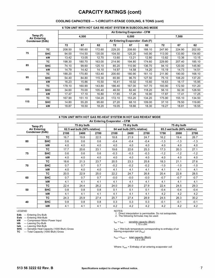
COOLING CAPACITIES — 1-CIRCUIT/SINGLE CIRCUIT 2-STAGE COOLING, 8.5 TONS
LEGEND NOTE: See Minimum-Maximum Airflow Ratings table on page 5. Do not operateoutside these limits.
RAS100(RTPF)
AMBIENT TEMPERATURE (F)85 95 105 115
EAT (db) EAT (db) EAT (db) EAT (db)75 80 85 75 80 85 75 80 85 75 80 85
2550
Cfm
EAT
(wb)
58 TC 85.4 85.4 95.6 81.6 81.6 93.2 78.1 78.1 89.2 74.1 74.1 84.6SHC 72.2 83.9 95.6 70.1 81.6 93.2 67.0 78.1 89.2 63.5 74.1 84.6
62 TC 91.1 91.1 91.1 86.5 86.5 88.6 81.7 81.7 86.7 76.2 76.2 84.1SHC 65.0 77.7 90.5 63.0 75.8 88.6 61.0 73.8 86.7 58.5 71.3 84.1
67 TC 101.8 101.8 101.8 96.9 96.9 96.9 91.2 91.2 91.2 85.1 85.1 85.1SHC 53.4 66.1 78.8 51.5 64.2 77.0 49.2 62.1 74.9 46.9 59.8 72.7
72 TC 113.4 113.4 113.4 107.8 107.8 107.8 101.7 101.7 101.7 94.9 94.9 94.9SHC 41.7 54.0 66.4 39.6 52.1 64.6 37.3 50.0 62.6 34.9 47.7 60.4
76 TC — 123.5 123.5 — 117.3 117.3 — 110.5 110.5 — 103.2 103.2SHC — 43.8 57.9 — 42.0 56.1 — 40.0 51.1 — 37.7 49.6
2975
Cfm
EAT
(wb)
58 TC 91.0 91.0 103.7 87.5 87.5 99.7 83.4 83.4 95.1 79.0 79.0 90.0SHC 78.3 91.0 103.7 75.2 87.5 99.7 71.8 83.4 95.1 67.9 79.0 90.0
62 TC 94.9 94.9 100.9 90.0 90.0 98.5 84.6 84.6 95.8 79.3 79.3 92.8SHC 71.4 86.1 100.9 69.0 83.7 98.5 66.5 81.2 95.8 63.9 78.4 92.8
67 TC 105.6 105.6 105.6 100.2 100.2 100.2 94.2 94.2 94.2 87.8 87.8 87.8SHC 57.8 72.6 87.4 55.7 70.6 85.4 53.4 68.4 83.3 51.0 66.0 80.9
72 TC 117.4 117.4 117.4 111.4 111.4 111.4 104.8 104.8 104.8 97.6 97.6 97.6SHC 43.9 58.4 73.0 41.7 56.4 71.1 39.4 54.2 68.9 36.9 51.8 66.6
76 TC — 127.4 127.4 — 120.9 120.9 — 113.7 113.7 — 106.0 106.0SHC — 46.7 59.3 — 44.7 58.2 — 42.5 56.5 — 40.2 54.5
3400
Cfm
EAT
(wb)
58 TC 95.6 95.6 108.9 91.7 91.7 104.4 87.4 87.4 99.5 82.6 82.6 94.0SHC 82.4 95.6 108.9 79.1 91.7 104.4 75.3 87.4 99.5 71.1 82.6 94.0
62 TC 97.4 97.4 108.3 92.6 92.6 106.1 88.2 88.2 101.6 82.9 82.9 97.3SHC 75.9 92.1 108.3 73.8 90.0 106.1 70.5 86.1 101.6 67.1 82.2 97.3
67 TC 108.2 108.2 108.2 102.5 102.5 102.5 96.3 96.3 96.3 89.6 89.6 89.6SHC 61.3 77.9 94.6 59.2 75.9 92.5 56.8 73.6 90.3 54.3 71.1 87.9
72 TC 120.1 120.1 120.1 113.8 113.8 113.8 106.9 106.9 106.9 99.4 99.4 99.4SHC 45.6 62.0 78.4 43.4 59.9 76.4 41.0 57.6 74.2 38.5 55.2 71.8
76 TC — 130.2 130.2 — 123.4 123.4 — 115.9 115.9 — 107.8 107.8SHC — 48.9 64.1 — 46.8 62.5 — 44.6 60.5 — 42.2 58.4
3825
Cfm
EAT
(wb)
58 TC 100.1 100.1 113.8 95.9 95.9 109.0 91.2 91.2 103.7 86.0 86.0 97.8SHC 86.3 100.1 113.8 82.7 95.9 109.0 78.6 91.2 103.7 74.1 86.0 97.8
62 TC 100.6 100.6 116.8 96.8 96.8 111.5 91.3 91.3 107.9 86.1 86.1 101.8SHC 81.2 99.0 116.8 77.6 94.5 111.5 74.6 91.3 107.9 70.3 86.1 101.8
67 TC 110.5 110.5 110.5 104.6 104.6 104.6 98.1 98.1 98.1 91.2 91.2 95.3SHC 65.1 83.7 102.3 62.9 81.5 100.1 60.5 79.2 97.9 57.9 76.6 95.3
72 TC 122.5 122.5 122.5 115.9 115.9 115.9 108.7 108.7 108.7 101.0 101.0 101.0SHC 47.4 65.8 84.2 45.2 63.7 82.2 42.7 61.3 79.9 40.2 58.8 77.5
76 TC — 132.6 132.6 — 125.6 125.6 — 117.8 117.8 — 109.5 109.5SHC — 51.1 68.6 — 49.0 66.8 — 46.7 64.8 — 44.2 62.5
4250
Cfm
EAT
(wb)
58 TC 103.4 103.4 117.5 99.0 99.0 112.5 94.0 94.0 106.8 88.5 88.5 100.7SHC 89.3 103.4 117.5 85.5 99.0 112.5 81.2 94.0 106.8 76.4 88.5 100.7
62 TC 104.2 104.2 120.3 99.1 99.1 117.0 94.1 94.1 111.2 88.6 88.6 104.7SHC 83.9 102.1 120.3 81.1 99.1 117.0 77.0 94.1 111.2 72.5 88.6 104.7
67 TC 112.2 112.2 112.2 106.2 106.2 106.7 99.5 99.5 104.2 92.3 92.3 101.5SHC 68.3 88.5 108.8 66.0 86.4 106.7 63.5 83.9 104.2 60.8 81.2 101.5
72 TC 124.2 124.2 124.2 117.5 117.5 117.5 110.1 110.1 110.1 102.2 102.2 102.2SHC 48.9 69.0 89.2 46.6 66.9 87.1 44.1 64.5 84.8 41.5 61.9 82.3
76 TC — 134.4 134.4 — 127.2 127.2 — 119.2 119.2 — 110.7 110.7SHC — 53.0 72.4 — 50.9 70.5 — 48.5 68.4 — 46.0 66.1
— — Do not operateCfm — Cubic feet per minute (supply air)EAT (db) — Entering Air Temperature (dry bulb)EAT (wb) — Entering Air Temperature (wet bulb)SHC — Sensible Heat Capacity (1000 Btuh) GrossTC — Total Capacity (1000 Btuh) Gross
CAPACITY RATINGS (cont)

14 Specifications subject to change without notice. 513 56 3222 02 Rev. B
COOLING CAPACITIES — 2-CIRCUIT/2-STAGE COOLING, 10 TONS
LEGEND NOTE: See Minimum-Maximum Airflow Ratings table on page 5. Do not operateoutside these limits.
RAS120(RTPF)
AMBIENT TEMPERATURE (F)85 95 105 115
EAT (db) EAT (db) EAT (db) EAT (db)75 80 85 75 80 85 75 80 85 75 80 85
3000
Cfm
EAT
(wb)
58 TC 107.6 107.6 121.9 102.5 102.5 116.2 96.8 96.8 109.7 90.5 90.5 102.6SHC 93.2 107.6 121.9 88.8 102.5 116.2 83.9 96.8 109.7 78.4 90.5 102.6
62 TC 113.6 113.6 116.5 107.1 107.1 113.4 99.7 99.7 109.8 91.8 91.8 104.9SHC 84.6 100.6 116.5 81.5 97.4 113.4 78.0 93.9 109.8 73.7 89.3 104.9
67 TC 124.4 124.4 124.4 118.4 118.4 118.4 111.5 111.5 111.5 103.3 103.3 103.3SHC 69.7 85.7 101.7 67.1 83.2 99.2 64.3 80.3 96.3 60.8 76.8 92.8
72 TC 135.8 135.8 135.8 129.7 129.7 129.7 122.8 122.8 122.8 115.0 115.0 115.0SHC 54.3 70.4 86.6 52.0 68.1 84.2 49.3 65.4 81.6 46.4 62.5 78.6
76 TC — 145.3 145.3 — 139.0 139.0 — 131.9 131.9 — 124.1 124.1SHC — 57.8 74.3 — 55.6 72.1 — 53.1 69.6 — 50.4 66.9
3500
Cfm
EAT
(wb)
58 TC 114.2 114.2 129.4 108.9 108.9 123.4 102.9 102.9 116.6 96.3 96.3 109.1SHC 98.9 114.2 129.4 94.3 108.9 123.4 89.1 102.9 116.6 83.4 96.3 109.1
62 TC 117.2 117.2 127.9 111.0 111.0 124.7 104.0 104.0 119.5 96.5 96.5 113.7SHC 91.1 109.5 127.9 88.1 106.4 124.7 83.9 101.7 119.5 79.3 96.5 113.7
67 TC 127.8 127.8 127.8 121.7 121.7 121.7 114.5 114.5 114.5 106.6 106.6 106.6SHC 73.8 92.3 110.8 71.3 89.8 108.3 68.4 87.0 105.5 65.2 83.8 102.3
72 TC 139.4 139.4 139.4 133.0 133.0 133.0 125.8 125.8 125.8 117.9 117.9 117.9SHC 56.0 74.6 93.1 53.7 72.2 90.8 51.0 69.6 88.2 48.1 66.7 85.4
76 TC — 148.8 148.8 — 142.2 142.2 — 134.9 134.9 — 126.8 126.8SHC — 60.2 79.5 — 58.0 77.1 — 55.4 74.5 — 52.7 71.6
4000
Cfm
EAT
(wb)
58 TC 119.0 119.0 134.9 114.0 114.0 129.2 108.0 108.0 122.4 101.1 101.1 114.6SHC 103.1 119.0 134.9 98.7 114.0 129.2 93.6 108.0 122.4 87.6 101.1 114.6
62 TC 120.3 120.3 137.1 114.7 114.7 132.8 108.2 108.2 127.5 101.3 101.3 119.3SHC 96.5 116.8 137.1 93.0 112.9 132.8 88.9 108.2 127.5 83.2 101.3 119.3
67 TC 130.5 130.5 130.5 124.1 124.1 124.1 116.8 116.8 116.8 108.7 108.7 111.1SHC 77.7 98.6 119.5 75.2 96.2 117.2 72.3 93.3 114.4 69.1 90.1 111.1
72 TC 142.1 142.1 142.1 135.5 135.5 135.5 128.2 128.2 128.2 120.0 120.0 120.0SHC 57.6 78.4 99.3 55.2 76.1 97.1 52.5 73.6 94.6 49.7 70.7 91.8
76 TC — 151.4 151.4 — 144.7 144.7 — 137.1 137.1 — — —SHC — 62.3 83.8 — 60.0 81.4 — 57.5 78.8 — — —
4500
Cfm
EAT
(wb)
58 TC 123.0 123.0 139.5 117.8 117.8 133.6 111.9 111.9 126.9 105.3 105.3 119.3SHC 106.6 123.0 139.5 102.1 117.8 133.6 97.0 111.9 126.9 91.2 105.3 119.3
62 TC 123.4 123.4 144.4 117.9 117.9 139.0 112.0 112.0 132.0 105.4 105.4 124.2SHC 100.9 122.7 144.4 96.9 117.9 139.0 92.1 112.0 132.0 86.6 105.4 124.2
67 TC 132.6 132.6 132.6 126.0 126.0 126.0 118.7 118.7 122.9 110.4 110.4 119.6SHC 81.4 104.6 127.9 78.9 102.3 125.7 76.1 99.5 122.9 72.9 96.2 119.6
72 TC 144.2 144.2 144.2 137.4 137.4 137.4 129.9 129.9 129.9 121.6 121.6 121.6SHC 59.0 82.1 105.2 56.6 79.8 103.1 54.0 77.3 100.7 51.1 74.5 98.0
76 TC — 153.4 153.4 — 146.6 146.6 — 138.9 138.9 — — —SHC — 64.1 87.8 — 61.9 85.6 — 59.4 83.0 — — —
5000
Cfm
EAT
(wb)
58 TC 126.5 126.5 143.3 121.2 121.2 137.4 115.1 115.1 130.5 108.4 108.4 122.8SHC 109.6 126.5 143.3 105.0 121.2 137.4 99.8 115.1 130.5 93.9 108.4 122.8
62 TC 126.5 126.5 149.1 121.3 121.3 142.9 115.2 115.2 135.8 108.5 108.5 127.8SHC 104.0 126.5 149.1 99.7 121.3 142.9 94.7 115.2 135.8 89.1 108.5 127.8
67 TC 134.2 134.2 135.9 127.5 127.5 133.8 120.1 120.1 131.0 111.9 111.9 127.6SHC 84.9 110.4 135.9 82.4 108.1 133.8 79.6 105.3 131.0 76.4 102.0 127.6
72 TC 145.8 145.8 145.8 139.0 139.0 139.0 131.3 131.3 131.3 122.9 122.9 122.9SHC 60.3 85.6 110.8 57.9 83.4 108.9 55.3 81.0 106.6 52.5 78.2 104.0
76 TC — 155.1 155.1 — 148.2 148.2 — — — — — —SHC — 65.9 91.5 — 63.7 89.5 — — — — — —
— — Do not operateCfm — Cubic feet per minute (supply air)EAT (db) — Entering Air Temperature (dry bulb)EAT (wb) — Entering Air Temperature (wet bulb)SHC — Sensible Heat Capacity (1000 Btuh) GrossTC — Total Capacity (1000 Btuh) Gross
CAPACITY RATINGS (cont)

513 56 3222 02 Rev. B Specifications subject to change without notice. 15
COOLING CAPACITIES — 2-CIRCUIT/2-STAGE COOLING, 10 TONS
LEGEND NOTES:1. Direct interpolation is permissible. Do not extrapolate.2. The following formulas may be used:
tlwb = Wet-bulb temperature corresponding to enthalpy of airleaving evaporator coil (hlwb)
Where: hewb = Enthalpy of air entering evaporator coil
10 TON COOLING CAPACITIES, RTPF UNIT WITH HOT GAS RE-HEAT SYSTEM IN SUBCOOLING MODE
Temp (F)Air Entering
Condenser (Edb)
Air Entering Evaporator - CFM3000/0.04 4000/0.06 5000/0.07
Air Entering Evaporator - Ewb (F)72 67 62 72 67 62 72 67 62
75TC 142.85 129.44 116.93 152.09 138.44 125.76 157.99 144.23 132.06
SHC 58.38 74.88 91.58 67.96 89.45 111.02 76.63 102.94 127.93kW 7.19 6.97 6.79 6.92 7.12 7.35 7.45 7.22 7.02
85TC 132.33 119.68 107.86 140.92 128.03 116.10 146.41 133.41 121.98
SHC 48.44 65.56 82.83 57.37 79.50 101.68 65.65 92.58 118.12kW 7.98 7.77 7.58 7.72 7.92 8.14 8.25 8.01 7.82
95TC 121.41 109.52 98.43 129.35 117.22 106.04 134.43 122.20 111.50
SHC 38.19 55.92 73.78 46.47 69.22 92.01 54.34 81.92 107.96kW 8.87 8.66 8.48 8.61 8.80 9.03 9.14 8.90 8.71
105TC 110.04 98.92 88.56 117.27 105.94 95.53 121.88 110.46 100.54
SHC 27.59 45.94 64.39 35.16 58.57 81.98 42.56 70.82 97.40kW 9.86 9.66 9.48 9.61 9.79 10.02 10.12 9.89 9.70
115TC 98.09 87.74 78.13 104.62 94.08 84.45 108.76 98.13 89.01
SHC 16.52 35.47 54.53 23.37 47.44 71.46 30.32 59.25 86.31kW 10.95 10.76 10.60 10.72 10.89 11.10 11.19 10.98 10.81
10 TON COOLING CAPACITIES, RTPF UNIT WITH HOT GAS RE-HEAT SYSTEM IN HOT GAS REHEAT MODEE
Temp (F)Air Entering
Condenser (Edb)
Air Entering Evaporator - Ewb (F)75 Dry Bulb 75 Dry Bulb 75 Dry Bulb
62.5 Wet Bulb 64 Wet Bulb 65.3 Wet Bulb(50% Relative) (56% Relative) (60% Relative)
Air Entering Evaporator - CFM3000 4000 5000 3000 4000 5000 3000 4000 5000
80TC 44.78 39.41 31.89 53.22 49.44 43.38 60.56 58.12 53.32
SHC -0.44 -0.57 -0.69 -0.37 -0.51 -0.61 -0.33 -0.46 -0.56kW 6.96 6.77 6.52 7.26 7.13 6.91 7.54 7.45 7.27
75TC 45.84 40.46 32.86 54.28 50.51 44.45 61.61 59.19 54.40
SHC 0.53 0.40 0.29 0.60 0.47 0.37 0.64 0.52 0.42kW 6.77 6.56 6.29 7.11 6.95 6.72 7.41 7.31 7.12
70TC 46.91 41.48 33.50 55.36 51.59 45.50 62.69 60.28 55.49
SHC 1.51 1.38 1.27 1.57 1.45 1.35 1.61 1.50 1.40kW 6.54 6.32 6.02 6.90 6.74 6.49 7.23 7.13 6.92
60TC 48.88 43.42 35.76 57.29 53.56 47.48 64.56 62.16 57.42
SHC 3.44 3.34 3.24 3.51 3.40 3.31 3.55 3.45 3.37kW 6.45 6.16 6.70 6.93 6.72 6.39 7.38 7.24 6.96
50TC 50.83 45.28 37.67 59.22 55.52 49.43 66.05 64.03 59.34
SHC 5.38 5.29 5.20 5.45 5.36 5.28 5.48 5.40 5.33kW 6.46 6.01 6.34 6.98 6.71 6.29 8.15 7.38 7.02
40TC 52.82 47.29 39.50 61.14 57.48 51.39 68.23 65.88 61.25
SHC 7.32 7.24 7.20 7.38 7.31 7.24 7.43 7.36 7.29kW 6.29 6.09 6.12 7.05 6.72 6.29 7.78 7.55 7.10
Edb — Entering Dry-BulbEwb — Entering Wet-BulbkW — Compressor Motor Power Inputldb — Leaving Dry-Bulblwb — Leaving Wet-BulbSHC — Sensible Heat Capacity (1000 Btuh) GrossTC — Total Capacity (1000 Btuh) Gross
tldb = tedb -sensible capacity (Btuh)
1.10 x cfm
hlwb = hewb -total capacity (Btuh)
4.5 x cfm
CAPACITY RATINGS (cont)

16 Specifications subject to change without notice. 513 56 3222 02 Rev. B
COOLING CAPACITIES — 1-CIRCUIT/2-STAGE COOLING, 10 TONS
LEGEND NOTE: See Minimum-Maximum Airflow Ratings table on page 5. Do not operateoutside these limits.
RAS119(RTPF)
AMBIENT TEMPERATURE (F)85 95 105 115
EAT (db) EAT (db) EAT (db) EAT (db)75 80 85 75 80 85 75 80 85 75 80 85
3000
Cfm
EAT
(wb)
58 TC 107.8 107.8 122.1 102.5 102.5 116.3 96.9 96.9 110.2 91.1 91.1 103.7SHC 93.4 107.8 122.1 88.7 102.5 116.3 83.7 96.9 110.2 78.5 91.1 103.7
62 TC 114.4 114.4 114.4 107.9 107.9 110.8 100.8 100.8 106.6 93.8 93.8 102.7SHC 83.7 99.0 114.4 80.0 95.4 110.8 76.0 91.3 106.6 72.2 87.5 102.7
67 TC 125.7 125.7 125.7 118.8 118.8 118.8 111.3 111.3 111.3 103.6 103.6 103.6SHC 68.7 83.9 99.1 65.1 80.4 95.6 61.4 76.6 91.9 57.5 72.8 88.1
72 TC 138.0 138.0 138.0 130.8 130.8 130.8 122.8 122.8 122.8 114.4 114.4 114.4SHC 53.8 68.6 83.4 50.3 65.2 80.1 46.6 61.5 76.5 42.7 57.7 72.8
76 TC — 148.9 148.9 — 141.1 141.1 — 132.5 132.5 — 123.3 123.3SHC — 55.8 72.3 — 52.7 69.2 — 49.2 62.7 — 45.5 59.7
3500
Cfm
EAT
(wb)
58 TC 114.0 114.0 129.1 108.4 108.4 122.9 102.4 102.4 116.3 96.2 96.2 109.4SHC 98.9 114.0 129.1 93.9 108.4 122.9 88.6 102.4 116.3 83.0 96.2 109.4
62 TC 118.1 118.1 125.6 111.3 111.3 121.6 104.1 104.1 117.5 96.9 96.9 112.5SHC 90.4 108.0 125.6 86.5 104.1 121.6 82.5 100.0 117.5 78.0 95.3 112.5
67 TC 129.4 129.4 129.4 122.2 122.2 122.2 114.4 114.4 114.4 106.4 106.4 106.4SHC 73.1 90.7 108.2 69.5 87.1 104.6 65.7 83.3 100.9 61.8 79.4 97.0
72 TC 141.9 141.9 141.9 134.3 134.3 134.3 126.0 126.0 126.0 117.2 117.2 117.2SHC 55.8 73.1 90.3 52.3 69.6 86.8 48.5 65.8 83.1 44.6 61.9 79.3
76 TC — 152.2 152.2 — 144.5 144.5 — 135.4 135.4 — 126.0 126.0SHC — 58.6 74.0 — 55.3 71.4 — 51.6 68.1 — 47.8 64.6
4000
Cfm
EAT
(wb)
58 TC 119.2 119.2 134.9 113.3 113.3 128.4 107.0 107.0 121.5 100.4 100.4 114.1SHC 103.5 119.2 134.9 98.2 113.3 128.4 92.6 107.0 121.5 86.6 100.4 114.1
62 TC 121.0 121.0 135.9 114.3 114.3 131.4 107.5 107.5 125.2 101.1 101.1 117.1SHC 96.5 116.2 135.9 92.4 111.9 131.4 87.3 106.2 125.2 81.5 99.3 117.1
67 TC 132.3 132.3 132.3 124.9 124.9 124.9 117.0 117.0 117.0 108.5 108.5 108.5SHC 77.3 97.2 117.0 73.6 93.5 113.3 69.8 89.7 109.5 65.8 85.6 105.5
72 TC 144.8 144.8 144.8 137.0 137.0 137.0 128.4 128.4 128.4 119.3 119.3 119.3SHC 57.6 77.2 96.7 54.1 73.6 93.2 50.2 69.8 89.4 46.2 65.9 85.5
76 TC — 155.4 155.4 — 146.8 146.8 — 137.7 137.7 — 127.9 127.9SHC — 61.0 79.4 — 57.5 76.2 — 53.8 72.7 — 49.8 69.0
4500
Cfm
EAT
(wb)
58 TC 123.4 123.4 139.6 117.4 117.4 132.9 110.8 110.8 125.6 103.8 103.8 117.9SHC 107.2 123.4 139.6 101.8 117.4 132.9 95.9 110.8 125.6 89.7 103.8 117.9
62 TC 124.0 124.0 143.3 118.1 118.1 136.3 111.2 111.2 129.4 103.9 103.9 122.7SHC 101.1 122.2 143.3 95.9 116.1 136.3 90.5 110.0 129.4 85.1 103.9 122.7
67 TC 134.6 134.6 134.6 127.0 127.0 127.0 118.9 118.9 118.9 110.2 110.2 113.8SHC 81.3 103.3 125.4 77.5 99.6 121.6 73.7 95.7 117.8 69.6 91.7 113.8
72 TC 147.0 147.0 147.0 139.1 139.1 139.1 130.3 130.3 130.3 121.0 121.0 121.0SHC 59.3 81.1 102.8 55.7 77.5 99.3 51.9 73.7 95.5 47.8 69.6 91.4
76 TC — 157.5 157.5 — 148.9 148.9 — 139.5 139.5 — 129.4 129.4SHC — 63.1 84.0 — 59.6 80.7 — 55.7 77.0 — 51.8 73.1
5000
Cfm
EAT
(wb)
58 TC 127.1 127.1 143.8 120.8 120.8 136.8 113.9 113.9 129.2 106.8 106.8 121.3SHC 110.5 127.1 143.8 104.8 120.8 136.8 98.7 113.9 129.2 92.4 106.8 121.3
62 TC 127.7 127.7 148.1 121.2 121.2 141.5 114.0 114.0 134.3 106.9 106.9 126.2SHC 104.4 126.3 148.1 99.3 120.4 141.5 93.7 114.0 134.3 87.6 106.9 126.2
67 TC 136.5 136.5 136.5 128.7 128.7 129.7 120.4 120.4 125.7 111.5 111.5 121.4SHC 85.1 109.3 133.5 81.3 105.5 129.7 77.3 101.5 125.7 73.1 97.3 121.4
72 TC 149.0 149.0 149.0 140.9 140.9 140.9 131.8 131.8 131.8 122.4 122.4 122.4SHC 60.9 84.9 108.8 57.3 81.3 105.2 53.4 77.3 101.3 49.4 73.3 97.2
76 TC — 159.2 159.2 — 150.5 150.5 — 140.8 140.8 — 130.6 130.6SHC — 65.1 88.3 — 61.5 84.8 — 57.6 81.0 — 53.6 76.9
— — Do not operateCfm — Cubic feet per minute (supply air)EAT (db) — Entering Air Temperature (dry bulb)EAT (wb) — Entering Air Temperature (wet bulb)SHC — Sensible Heat Capacity (1000 Btuh) GrossTC — Total Capacity (1000 Btuh) Gross
CAPACITY RATINGS (cont)

513 56 3222 02 Rev. B Specifications subject to change without notice. 17
COOLING CAPACITIES — 2-CIRCUIT/2-STAGE COOLING, 12.5 TONS
LEGEND NOTE: See Minimum-Maximum Airflow - Natural Gas and Propane Ratings onpage 5. Do not operate outside these limits.
RAS150(RTPF)
AMBIENT TEMPERATURE (F)85 95 105 115
EAT (db) EAT (db) EAT (db) EAT (db)75 80 85 75 80 85 75 80 85 75 80 85
3600
Cfm
EAT
(wb)
58 TC 127.6 127.6 142.9 121.7 121.7 137.6 115.0 115.0 130.0 108.3 108.3 122.6SHC 110.3 126.6 142.9 105.8 121.7 137.6 99.9 115.0 130.0 94.1 108.3 122.6
62 TC 136.1 136.1 136.1 131.1 131.1 131.1 123.8 123.8 124.5 114.9 114.9 120.3SHC 96.6 112.8 129.0 94.7 111.2 127.7 91.4 108.0 124.5 87.3 103.8 120.3
67 TC 146.2 146.2 146.2 142.0 142.0 142.0 136.2 136.2 136.2 128.8 128.8 128.8SHC 78.5 94.4 110.3 76.9 93.1 109.2 74.7 91.0 107.3 71.7 88.1 104.6
72 TC 155.9 155.9 155.9 152.4 152.4 152.4 147.2 147.2 147.2 140.1 140.1 140.1SHC 60.1 76.6 93.2 58.7 75.2 91.7 56.8 73.3 89.7 54.2 70.6 87.0
76 TC — 163.0 163.0 — 160.0 160.0 — 155.1 155.1 — 148.2 148.2SHC — 62.0 81.8 — 61.1 80.9 — 59.5 79.3 — 57.0 76.3
4200
Cfm
EAT
(wb)
58 TC 132.2 132.2 149.5 128.2 128.2 144.9 121.9 121.9 137.8 115.0 115.0 130.1SHC 115.0 132.2 149.5 111.5 128.2 144.9 106.0 121.9 137.8 99.9 115.0 130.1
62 TC 139.6 139.6 139.6 134.7 134.7 138.0 128.0 128.0 135.6 119.1 119.1 131.2SHC 102.5 120.8 139.0 100.8 119.4 138.0 98.1 116.8 135.6 93.9 112.6 131.2
67TC 149.5 149.5 149.5 145.4 145.4 145.4 139.6 139.6 139.6 132.1 132.1 132.1
SHC 81.8 99.6 117.4 80.6 98.7 116.8 78.5 96.9 115.2 75.7 94.3 112.8
72 TC 159.0 159.0 159.0 155.5 155.5 155.5 150.3 150.3 150.3 143.1 143.1 143.1SHC 61.4 79.6 97.8 60.2 78.5 96.8 58.3 76.7 95.0 55.8 74.2 92.5
76 TC — 165.7 165.7 — 162.8 162.8 — 157.8 157.8 — 150.8 150.8SHC — 64.6 87.7 — 63.5 86.3 — 61.5 83.3 — 58.9 79.9
4800
Cfm
EAT
(wb)
58 TC 136.7 136.7 154.5 133.0 133.0 150.3 127.7 127.7 144.3 120.6 120.6 136.4SHC 118.9 136.7 154.5 115.7 133.0 150.3 111.0 127.7 144.3 104.9 120.6 136.4
62 TC 142.2 142.2 147.8 137.4 137.4 147.1 131.0 131.0 144.7 122.8 122.8 140.3SHC 107.7 127.8 147.8 106.2 126.7 147.1 103.6 124.2 144.7 99.3 119.8 140.3
67 TC 152.1 152.1 152.1 148.0 148.0 148.0 142.2 142.2 142.2 134.6 134.6 134.6SHC 84.8 104.3 123.7 83.8 103.8 123.7 82.0 102.3 122.6 79.4 99.9 120.4
72 TC 161.3 161.3 161.3 157.8 157.8 157.8 152.5 152.5 152.5 145.4 145.4 145.4SHC 62.6 82.2 101.9 61.4 81.4 101.3 59.7 79.7 99.8 57.2 77.3 97.5
76 TC — 167.7 167.7 — 164.9 164.9 — 159.9 159.9 — 152.8 152.8SHC — 66.4 91.4 — 65.0 89.2 — 63.1 86.4 — 60.5 83.1
5400
Cfm
EAT
(wb)
58 TC 140.5 140.5 158.8 136.9 136.9 154.7 131.8 131.8 149.0 125.2 125.2 141.6SHC 122.2 140.5 158.8 119 136.9 154.7 114.7 131.8 149.0 108.9 125.2 141.6
62 TC 144.3 144.3 155.7 139.6 139.6 155.0 133.5 133.5 152.4 125.8 125.8 147.8SHC 112.2 133.9 155.7 110.9 132.9 155.0 108.1 130.2 152.4 103.9 125.8 147.8
67TC 154.2 154.2 154.2 150.0 150.0 150.0 144.2 144.2 144.2 136.7 136.7 136.7
SHC 87.6 108.6 129.6 86.8 108.5 130.1 85.2 107.3 129.4 82.8 105.1 127.4
72 TC 163.1 163.1 163.1 159.7 159.7 159.7 154.3 154.3 154.3 147.1 147.1 147.1SHC 63.6 84.6 105.6 62.5 83.9 105.4 60.8 82.5 104.2 58.4 80.2 102.0
76 TC — 169.3 169.3 — 166.5 166.5 — 161.5 161.5 — 154.2 154.2SHC — 67.6 93.7 — 66.4 91.7 — 64.5 89.2 — 61.9 86.1
6000
Cfm
EAT
(wb)
58 TC 143.6 143.6 162.3 140.1 140.1 158.3 135.1 135.1 152.7 128.7 128.7 145.5SHC 124.9 143.6 162.3 121.8 140.1 158.3 117.5 135.1 152.7 111.9 128.7 145.5
62 TC 146.1 146.1 162.4 141.7 141.7 161.5 135.6 135.6 159.2 128.8 128.8 151.2SHC 116.1 139.3 162.4 114.7 138.1 161.5 112.1 135.6 159.2 106.4 128.8 151.2
67TC 155.8 155.8 155.8 151.6 151.6 151.6 145.9 145.9 145.9 138.3 138.3 138.3
SHC 90.1 112.6 135.0 89.6 112.8 136.0 88.3 112.0 135.8 85.9 110.0 134.1
72TC 164.5 164.5 164.5 161.2 161.2 161.2 155.8 155.8 155.8 148.5 148.5 148.5
SHC 64.5 86.7 108.9 63.5 86.3 109.1 61.9 85.1 108.2 59.6 82.9 106.3
76TC — 170.6 170.6 — 167.8 167.8 — 162.8 162.8 — 155.5 155.5
SHC — 68.7 95.8 — 67.5 94.1 — 65.7 91.8 — 63.3 88.8
— — Do not operateCfm — Cubic feet per minute (supply air)EAT (db) — Entering Air Temperature (dry bulb)EAT (wb) — Entering Air Temperature (wet bulb)SHC — Sensible Heat Capacity (1000 Btuh) GrossTC — Total Capacity (1000 Btuh) Gross
CAPACITY RATINGS (cont)

18 Specifications subject to change without notice. 513 56 3222 02 Rev. B
COOLING CAPACITIES — 2-CIRCUIT/2-STAGE COOLING, 12.5 TONS
LEGEND NOTES:1. Direct interpolation is permissible. Do not extrapolate.2. The following formulas may be used:
tlwb = Wet-bulb temperature corresponding to enthalpy of airleaving evaporator coil (hlwb)
Where: hewb = Enthalpy of air entering evaporator coil
12.5 TON COOLING CAPACITIES, RTPF UNIT WITH HOT GAS RE-HEAT SYSTEM IN SUBCOOLING MODE
Temp (F)Air Entering
Condenser (Edb)
Air Entering Evaporator - CFM3750/0.02 5000/0.06 6250/0.05
Air Entering Evaporator - Ewb (F)72 67 62 72 67 62 72 67 62
75TC 183.66 166.86 151.43 194.90 177.83 162.05 201.97 184.84 170.53
SHC 79.39 100.52 121.91 91.70 119.42 147.05 102.94 137.00 166.71kW 9.82 9.63 9.46 9.58 9.76 9.96 10.04 9.84 9.67
85TC 172.71 156.78 142.09 183.32 167.13 152.17 189.98 173.73 160.25
SHC 69.03 90.92 112.95 80.69 109.17 137.51 91.49 126.33 156.65kW 10.82 10.63 10.45 10.57 10.76 10.96 11.04 10.84 10.67
95TC 161.37 146.24 132.38 171.36 156.04 141.86 177.62 162.22 149.50
SHC 58.44 81.04 103.77 69.42 98.67 127.71 79.83 115.45 146.15kW 11.92 11.73 11.56 11.68 11.86 12.05 12.14 11.93 11.77
105TC 149.57 135.32 122.21 158.89 144.45 131.10 164.74 150.27 138.35
SHC 47.57 70.92 94.32 57.85 87.91 117.61 67.79 104.26 135.30kW 13.12 12.94 12.77 12.89 13.06 13.24 13.32 13.13 12.97
115TC 137.22 123.88 111.55 145.85 132.33 119.84 151.27 137.71 126.67
SHC 36.31 60.47 84.57 45.87 76.77 107.19 55.34 92.66 123.98kW 14.41 14.25 14.10 14.20 14.35 14.53 14.59 14.42 14.28
12.5 TON COOLING CAPACITIES, RTPF UNIT WITH HOT GAS RE-HEAT SYSTEM IN HOT GAS REHEAT MODE
Temp (F)Air Entering
Condenser (Edb)
Air Entering Evaporator - Ewb (F)75 Dry Bulb 75 Dry Bulb 75 Dry Bulb
62.5 Wet Bulb 64 Wet Bulb 65.3 Wet Bulb(50% Relative) (56% Relative) (60% Relative)
Air Entering Evaporator - CFM3750 5000 6250 3750 5000 6250 3750 5000 6250
80TC 52.42 45.88 36.99 62.64 58.07 51.07 71.56 68.64 63.23
SHC -0.39 -0.54 -0.67 -0.31 -0.46 -0.58 -0.26 -0.40 -0.52kW 9.65 9.39 9.07 9.97 9.77 9.50 10.25 10.11 9.89
75TC 53.45 46.63 36.10 63.77 59.11 51.87 72.76 69.80 64.31
SHC 0.59 0.44 0.30 0.67 0.52 0.40 0.72 0.58 0.47kW 9.09 8.83 8.49 9.39 9.20 8.94 9.67 9.53 9.32
70TC 54.33 46.91 37.58 64.77 60.01 52.30 73.80 70.80 65.24
SHC 1.56 1.41 1.29 1.64 1.50 1.38 1.70 1.56 1.45kW 8.81 8.53 8.62 9.15 8.94 8.65 9.46 9.31 9.08
60TC 55.47 49.48 40.48 66.62 62.07 54.88 75.68 72.76 67.28
SHC 3.50 3.38 3.27 3.59 3.47 3.36 3.65 3.52 3.42kW 8.36 8.84 8.98 9.88 9.56 9.10 9.83 9.64 9.31
50TC 58.33 51.72 42.81 68.72 63.93 55.84 77.74 74.77 69.24
SHC 5.47 5.35 5.24 5.54 5.43 5.32 5.60 5.49 5.39kW 8.98 9.25 9.43 9.33 8.97 8.73 9.55 9.33 9.70
40TC 60.33 53.69 46.89 70.67 65.93 49.83 79.46 76.62 71.24
SHC 7.42 7.31 7.22 7.49 7.39 7.23 7.55 7.45 7.37kW 9.16 9.88 9.06 9.50 9.05 9.47 10.31 10.00 9.48
Edb — Entering Dry-BulbEwb — Entering Wet-BulbkW — Compressor Motor Power Inputldb — Leaving Dry-Bulblwb — Leaving Wet-BulbSHC — Sensible Heat Capacity (1000 Btuh) GrossTC — Total Capacity (1000 Btuh) Gross
tldb = tedb -sensible capacity (Btuh)
1.10 x cfm
hlwb = hewb -total capacity (Btuh)
4.5 x cfm
CAPACITY RATINGS (cont)

513 56 3222 02 Rev. B Specifications subject to change without notice. 19
COOLING CAPACITIES — 2-CIRCUIT/2-STAGE COOLING, 15 TONS
LEGEND NOTE: See Minimum-Maximum Airflow - Natural Gas and Propane Ratings onpage 5. Do not operate outside these limits.
RAS180(RTPF)
AMBIENT TEMPERATURE (F)85 95 105 115
EAT (db) EAT (db) EAT (db) EAT (db)75 80 85 75 80 85 75 80 85 75 80 85
4500
Cfm
EAT
(wb)
58 TC 156.6 156.6 175.2 149.4 149.4 169.1 141.6 141.6 160.2 133.3 133.3 150.9SHC 134.7 154.9 175.2 129.8 149.4 169.1 123.0 141.6 160.2 115.7 133.3 150.9
62 TC 166.7 166.7 166.9 158.0 158.0 162.6 147.6 147.6 157.2 136.8 136.8 150.3SHC 122.8 144.9 166.9 118.6 140.6 162.6 113.5 135.3 157.2 107.4 128.8 150.3
67 TC 184.1 184.1 184.1 175.6 175.6 175.6 165.6 165.6 165.6 154.5 154.5 154.5SHC 101.6 123.7 145.7 98.1 120.2 142.3 94.0 116.1 138.2 89.4 111.5 133.6
72 TC 200.3 200.3 200.3 192.0 192.0 192.0 182.9 182.9 182.9 172.2 172.2 172.2SHC 78.7 101.1 123.5 75.5 97.9 120.2 72.1 94.4 116.7 68.2 90.5 112.7
76 TC — 211.4 211.4 — 203.1 203.1 — 193.8 193.8 — 183.9 183.9SHC — 82.2 107.0 — 79.3 103.8 — 76.0 100.2 — 72.6 96.5
5250
Cfm
EAT
(wb)
58 TC 165.2 165.2 186.9 158.2 158.2 179.0 150.0 150.0 169.7 141.3 141.3 160.0SHC 143.5 165.2 186.9 137.4 158.2 179.0 130.2 150.0 169.7 122.7 141.3 160.0
62 TC 172.3 172.3 181.7 163.4 163.4 176.9 153.1 153.1 169.3 143.4 143.4 161.4SHC 131.6 156.6 181.7 127.1 152.0 176.9 120.5 144.9 169.3 114.1 137.8 161.4
67 TC 189.5 189.5 189.5 180.9 180.9 180.9 170.7 170.7 170.7 159.1 159.1 159.1SHC 107.2 132.4 157.5 103.8 129.0 154.1 99.9 125.1 150.4 95.3 120.6 145.8
72 TC 205.0 205.0 205.0 196.5 196.5 196.5 187.1 187.1 187.1 176.4 176.4 176.4SHC 80.9 106.1 131.3 77.7 102.9 128.1 74.4 99.5 124.7 70.6 95.8 121.0
76 TC — 215.4 215.4 — 206.8 206.8 — 197.1 197.1 — 186.9 186.9SHC — 85.0 113.0 — 82.0 109.8 — 78.8 106.4 — 75.4 102.8
6000
Cfm
EAT
(wb)
58 TC 172.7 172.7 195.4 165.5 165.5 187.3 157.1 157.1 177.8 148.1 148.1 167.7SHC 150.0 172.7 195.4 143.8 165.5 187.3 136.4 157.1 177.8 128.6 148.1 167.7
62 TC 176.6 176.6 195.7 168.1 168.1 187.6 158.9 158.9 180.2 148.9 148.9 172.1SHC 139.6 167.7 195.7 133.2 160.4 187.6 127.1 153.7 180.2 120.7 146.4 172.1
67 TC 193.6 193.6 193.6 184.8 184.8 184.8 174.7 174.7 174.7 162.7 162.7 162.7SHC 112.3 140.3 168.3 108.9 137.0 165.2 105.2 133.5 161.7 100.7 129.0 157.3
72 TC 208.4 208.4 208.4 199.6 199.6 199.6 190.2 190.2 190.2 179.5 179.5 179.5SHC 82.7 110.5 138.3 79.6 107.3 135.1 76.2 104.0 131.8 72.6 100.6 128.5
76 TC — 218.2 218.2 — 209.5 209.5 — 199.5 199.5 — 189.0 189.0SHC — 87.5 118.6 — 84.5 115.2 — 81.1 111.3 — 77.5 107.3
6750
Cfm
EAT
(wb)
58 TC 178.8 178.8 202.4 171.6 171.6 194.2 163.1 163.1 184.6 153.8 153.8 174.1SHC 155.3 178.8 202.4 149.0 171.6 194.2 141.6 163.1 184.6 133.5 153.8 174.1
62 TC 181.0 181.0 203.6 173.0 173.0 197.5 163.8 163.8 190.1 153.9 153.9 181.1SHC 144.1 173.9 203.6 139.1 168.3 197.5 133.3 161.7 190.1 126.7 153.9 181.1
67 TC 196.8 196.8 196.8 187.9 187.9 187.9 177.7 177.7 177.7 165.5 165.5 167.9SHC 117.0 147.7 178.4 113.7 144.5 175.4 110.1 141.1 172.2 105.6 136.8 167.9
72 TC 211.0 211.0 211.0 202.2 202.2 202.2 192.5 192.5 192.5 181.8 181.8 181.8SHC 84.3 114.5 144.7 81.2 111.5 141.7 77.9 108.1 138.4 74.4 104.9 135.4
76 TC — 220.2 220.2 — 211.5 211.5 — 201.3 201.3 — 190.6 190.6SHC — 89.5 122.8 — 86.4 119.4 — 83.0 115.4 — 79.4 111.5
7500
Cfm
EAT
(wb)
58 TC 183.9 183.9 208.2 176.6 176.6 199.8 168.2 168.2 190.3 158.6 158.6 179.5SHC 159.7 183.9 208.2 153.3 176.6 199.8 146.0 168.2 190.3 137.7 158.6 179.5
62 TC 185.1 185.1 212.5 177.1 177.1 206.2 168.3 168.3 197.9 158.7 158.7 186.7SHC 149.5 181.0 212.5 144.5 175.4 206.2 138.7 168.3 197.9 130.8 158.7 186.7
67 TC 199.3 199.3 199.3 190.3 190.3 190.3 180.0 180.0 181.7 167.8 167.8 177.8SHC 121.3 154.6 187.9 118.1 151.6 185.1 114.4 148.1 181.7 110.1 144.0 177.8
72 TC 213.0 213.0 213.0 204.1 204.1 204.1 194.2 194.2 194.2 183.5 183.5 183.5SHC 85.8 118.2 150.5 82.7 115.2 147.7 79.4 111.9 144.4 76.0 108.8 141.6
76 TC — 221.9 221.9 — 213.0 213.0 — 202.7 202.7 — 191.8 191.8SHC — 91.2 126.5 — 88.2 123.1 — 84.7 119.2 — 81.2 115.3
— — Do not operateCfm — Cubic feet per minute (supply air)EAT (db) — Entering Air Temperature (dry bulb)EAT (wb) — Entering Air Temperature (wet bulb)SHC — Sensible Heat Capacity (1000 Btuh) GrossTC — Total Capacity (1000 Btuh) Gross
CAPACITY RATINGS (cont)

20 Specifications subject to change without notice. 513 56 3222 02 Rev. B
COOLING CAPACITIES — 2-CIRCUIT/2-STAGE COOLING, 15 TONS
LEGEND NOTES:1. Direct interpolation is permissible. Do not extrapolate.2. The following formulas may be used:
tlwb = Wet-bulb temperature corresponding to enthalpy of airleaving evaporator coil (hlwb)
Where: hewb = Enthalpy of air entering evaporator coil
15 TON COOLING CAPACITIES, UNIT WITH HOT GAS RE-HEAT SYSTEM IN SUBCOOLING MODE
Temp (F) Air Entering
Condenser (Edb)
Air Entering Evaporator - CFM4500/0.02 6000/0.06 7500/0.05
Air Entering Evaporator - Ewb (F)72 67 62 72 67 62 72 67 62
75TC 204.40 186.30 168.20 218.40 199.60 180.90 229.60 210.40 191.20
SHC 98.90 118.10 137.20 114.80 133.70 152.60 127.60 146.20 164.90kW 11.57 11.22 10.77 11.78 11.45 11.00 12.06 11.64 11.35
85TC 189.20 171.70 154.10 203.00 184.80 166.70 214.10 195.50 176.90
SHC 79.50 103.40 127.30 96.50 120.20 144.00 110.20 133.70 157.30kW 12.59 12.24 11.81 12.81 12.50 12.03 13.05 12.66 12.47
95TC 174.00 157.00 140.00 187.60 170.10 152.50 198.60 180.60 162.70
SHC 60.00 88.70 117.50 78.20 106.80 135.30 92.90 121.30 149.70kW 13.68 13.35 12.86 13.91 13.57 13.05 14.15 13.75 13.47
105TC 158.80 142.30 125.80 172.20 155.30 138.30 183.10 165.70 148.40
SHC 40.50 74.10 107.70 59.90 93.30 126.70 75.50 108.80 142.00kW 14.67 14.41 13.88 14.90 14.55 14.10 15.15 14.73 14.53
115TC 143.60 127.60 111.70 156.80 140.50 124.10 167.60 150.90 134.20
SHC 21.00 59.40 97.80 41.60 79.90 118.10 58.10 96.30 134.20kW 15.77 15.38 14.88 15.88 15.65 15.10 16.12 15.84 15.54
15 TON COOLING CAPACITIES, UNIT WITH HOT GAS RE-HEAT SYSTEM IN HOT GAS REHEAT MODE
Temp (F)Air Entering
Condenser (Edb)
Air Entering Evaporator - Ewb (F)75 Dry Bulb 75 Dry Bulb 75 Dry Bulb
62.5 Wet Bulb 64 Wet Bulb 65.3 Wet Bulb(50% Relative) (56% Relative) (60% Relative)
Air Entering Evaporator - CFM4500 6000 7500 4500 6000 7500 4500 6000 7500
80TC 83.75 84.85 88.95 86.65 91.90 92.90 87.90 91.75 96.30
SHC 37.50 42.80 55.10 30.90 40.40 44.50 24.80 29.30 34.10kW 10.50 11.49 11.60 10.56 10.65 11.70 11.60 11.72 11.77
75TC 85.00 86.00 90.50 88.05 93.60 94.65 89.20 93.45 97.85
SHC 40.00 45.00 57.30 33.20 42.30 46.90 26.90 31.50 36.30kW 10.16 11.15 11.25 10.21 10.31 11.33 11.26 11.35 11.42
70TC 86.15 87.35 91.50 89.20 94.30 96.10 90.40 94.10 98.95
SHC 42.10 47.50 59.80 35.50 45.30 49.50 29.50 33.90 38.70kW 9.84 10.83 10.94 10.02 10.13 11.03 10.95 11.05 11.12
60TC 88.90 90.10 94.25 92.00 97.10 98.20 93.20 96.90 101.75
SHC 46.80 52.30 64.60 40.20 50.10 54.10 34.10 38.60 43.40kW 9.37 10.36 10.44 9.42 9.52 10.55 10.45 10.57 10.64
50TC 91.70 92.80 97.00 94.80 99.90 101.00 96.10 99.70 104.20
SHC 51.50 57.10 69.40 44.80 54.80 58.90 38.70 43.20 49.00kW 9.12 10.09 10.16 9.17 9.28 10.26 10.17 10.26 10.32
40TC 94.45 95.60 99.80 97.45 102.55 103.70 98.65 102.35 107.00
SHC 56.30 61.40 73.70 49.70 59.20 63.30 43.60 48.10 52.90kW 9.05 10.02 10.10 9.10 9.21 10.18 10.11 10.20 10.26
Edb — Entering Dry-BulbEwb — Entering Wet-BulbkW — Compressor Motor Power Inputldb — Leaving Dry-Bulblwb — Leaving Wet-BulbSHC — Sensible Heat Capacity (1000 Btuh) GrossTC — Total Capacity (1000 Btuh) Gross
tldb = tedb -sensible capacity (Btuh)
1.10 x cfm
hlwb = hewb -total capacity (Btuh)
4.5 x cfm
CAPACITY RATINGS (cont)

513 56 3222 02 Rev. B Specifications subject to change without notice. 21
PHYSICAL DATA (COOLING) — 6 TONS RAS RAS-072
REFRIGERATION SYSTEM# Circuits / # Comp. / Type 1 / 1 / Scroll
Refrig. (R-410A)(lbs-oz) 14 - 2Hot Gas Reheat refrig. charge A/B (lbs-oz) 22 - 5
Metering device Accutrol*Hot Gas Reheat Metering Device Accutrol + TXV
High-press. Trip / Reset (psig) 630 / 505Low-press. Trip / Reset (psig) 54 / 117
Compressor Capacity Staging (%) 100%EVAP. COIL
Material Cu / AlCoil Type (Tube Dia.) 3/8" RTPF
Rows / FPI 4 / 15Total face area (ft2) 7.3
Condensate drain conn. size 3/4"HOT GAS RE-HEAT COIL
Material Cu / AlCoil Type (Tube dia.) 3/8" RTPF
Rows / FPI 2 / 17Total face area (ft2) 5.2
EVAPORATOR FAN AND MOTOR
Standard Static
Motor Qty. / Belt Qty. / Driver Type 1 / BeltMax BHP 2.4
RPM range 1073-1457Motor frame size 56
Fan Qty. / Type 1 / CentrifugalFan Diameter (in.) 10 x 10
Medium Static
Motor Qty. / Belt Qty. / Driver Type 1 / BeltMax BHP 2.9†
RPM range 1173-1518Motor frame size 56
Fan Qty. / Type 1 / CentrifugalFan Diameter (in.) 10 x 10
High Static
Motor Qty. / Belt Qty. / Driver Type 1 / BeltMax BHP 3.7
RPM range 1474-1788Motor frame size 56
Fan Qty. / Type 1 / CentrifugalFan Diameter (in.) 10 x 10
CONDENSER COILMaterial (Tube/Fin) Cu / Al
Coil type 3/8" RTPFRows / FPI 2 / 17
Total Face Area (ft2) 21.3COND. FAN / MOTOR
Qty / Motor Drive Type 1 / DirectMotor HP / RPM 1/4 / 1100
Fan diameter (in.) 22FILTERS
RA Filter # / Size (in.) 4 / 16 x 16 x 2OA inlet screen # / Size (in.) 1 / 20 x 24 x 1
* Accutrol is a trademark of Accutrol LLC.† 575V motor utilizes 3.7 BHP.
PHYSICAL DATA

22 Specifications subject to change without notice. 513 56 3222 02 Rev. B
PHYSICAL DATA (COOLING) — 7.5-8.5 TONS
LEGEND
RAS RAS090 RAS089* RAS102 RAS100REFRIGERATION SYSTEM
# Circuits / # Comp. / Type 2 / 2 / Scroll 1 / 1 / 2-Stage Scroll 2 / 2/ Scroll 1 / 1 / 2-Stage ScrollRTPF models R-410A charge A/B (lbs-oz) 8-5 / 8-2 12-0 10-5 / 10-12 15-5
Alternate (Hot Gas Reheat) R-410A charge A/B (lbs- oz) 13-3 / 13-3 — 16-13 / 16-13 —Metering device Accutrol Accutrol + TXV Accutrol Accutrol + TXV
Alternate Hot Gas Reheat Metering Device Accutrol + TXV — Accutrol + TXV —High-press. Trip / Reset (psig) 630 / 505 630 / 505 630 / 505 630 / 505Low-press. Trip / Reset (psig) 54 / 117 54 / 117 54 / 117 54 / 117
Compressor Capacity Staging (%) 50 / 100% 66 / 100% 50% / 100% 66 / 100%EVAP. COIL
Material Cu / Al Cu / Al Cu / Al Cu / AlCoil Type (Tube Dia.) 3/8" RTPF 3/8" RTPF 3/8" RTPF 3/8" RTPF
Rows / FPI 3 / 15 3 / 15 3 / 15 3 / 15Total face area (ft2) 8.9 8.9 11.1 11.1
Condensate drain conn. size 3/4" 3/4" 3/4" 3/4"HOT GAS RE-HEAT COIL
Material Cu / Al — Cu / Al —Coil Type (Tube Dia.) 3/8" RTPF — 3/8" RTPF —
Rows / FPI 2 / 17 — 2 / 17 —Total face area (ft2) 3.9 — 5.2 —
EVAPORATOR FAN AND MOTOR
Standard Static
Motor Qty. / Driver Type 1 / Belt 1 / Belt 1 / Belt 1 / BeltMax BHP 1.7 1.7 1.7 1.7
RPM range 489-747 489-747 518-733 518-733Motor frame size 56 56 56 56
Fan Qty. / Type 1 / Centrifugal 1 / Centrifugal 1 / Centrifugal 1 / CentrifugalFan Diameter (in.) 15 x 15 15 x 15 15 x 15 15 x 15
MediumStatic
Motor Qty. / Driver Type 1 / Belt 1 / Belt 1 / Belt 1 / BeltMax BHP 2.9 † 2.9 2.9 2.4
RPM range 733-949 733-949 690-936 690-936Motor frame size 56 56 56 56
Fan Qty. / Type 1 / Centrifugal 1 / Centrifugal 1 / Centrifugal 1 / CentrifugalFan Diameter (in.) 15 x 15 15 x 15 15 x 15 15 x 15
HighStatic
Motor Qty. / Driver Type 1 / Belt
N/A
1 / Belt 1 / BeltMax BHP 4.7 3.7 3.7
RPM range 909-1102 838-1084 838-1084Motor frame size 14 56 56
Fan Qty. / Type 1 / Centrifugal 1 / Centrifugal 1 / CentrifugalFan Diameter (in.) 15 x 15 15 x 15 15 x 15
CONDENSER COILMaterial (Tube/Fin) Cu / Al Cu / Al Cu / Al Cu / Al
Coil type 3/8" RTPF 5/16" RTPF 3/8" RTPF 3/8" RTPFRows / FPI 2 / 17 2 / 18 2 / 17 2 / 17
Total Face Area (ft2) 20.5 20.5 25.1 21.4COND. FAN / MOTOR
Qty / Motor Drive Type 2 / Direct 2 / Direct 2 / Direct 2 / DirectMotor HP / RPM 1/4 / 1100 1/4 / 1100 1/4 / 1100 1/4 / 1100
Fan diameter (in.) 22 22 22 22FILTERS
RA Filter # / Size (in.) 4 / 16 x 20 x 2 4 / 16 x 20 x 2 4 / 20 x 20 x 2 4 / 20 x 20 x 2OA inlet screen # / Size (in.) 1 / 20 x 24 x 1 1 / 20 x 24 x 1 1 / 20 x 24 x 1 1 / 20 x 24 x 1
— Not applicable* RAS089 is not available in 575 volt models.† 575V motor utilizes 3.7 BHP.
PHYSICAL DATA (cont)

513 56 3222 02 Rev. B Specifications subject to change without notice. 23
PHYSICAL DATA (COOLING) — 10-15 TONS
LEGEND
RAS RAS120 RAS119 RAS150 RAS180REFRIGERATION SYSTEM
# Circuits / # Comp. / Type 2 / 2 / Scroll 1 / 1 / 2-Stage Scroll 2 / 2 / Scroll 2 / 2/ ScrollRTPF models R-410A charge A/B (lbs-oz) 10-5 / 10-3 21-0 11-0 / 11-6 15-14 / 16-12
Alternate (Hot Gas Reheat) R-410A charge A/B (lbs- oz) 16-10 / 16-0 — 17-10 / 18-3 —Metering device Accutrol Accutrol + TXV Accutrol Accutrol
Alternate Hot Gas Reheat Metering Device Accutrol + TXV — Accutrol + TXV —High-press. Trip / Reset (psig) 630 / 505 630 / 505 630 / 505 630 / 505Low-press. Trip / Reset (psig) 54 / 117 54 / 117 54 / 117 54 / 117
Compressor Capacity Staging (%) 50% / 100% 100% 50% / 100% 50% / 100%EVAP. COIL
Material Cu / Al Cu / Al Cu / Al Cu / AlCoil Type (Tube Dia.) 3/8" RTPF 3/8" RTPF 3/8" RTPF 3/8" RTPF
Rows / FPI 4 / 15 4 / 15 4 / 15 3 / 15Total face area (ft2) 11.1 11.1 11.1 17.5
Condensate drain conn. size 3/4" 3/4" 3/4" 3/4"HOT GAS RE-HEAT COIL
Material Cu / Al — Cu / Al Cu / AlCoil Type (Tube Dia.) 3/8" RTPF — 3/8" RTPF 3/8" RTPF
Rows / FPI 2 / 17 — 2 / 17 2 / 17Total face area (ft2) 8.4 — 8.4 13.8
EVAPORATOR FAN AND MOTOR
Standard Static
Motor Qty. / Driver Type 1 / Belt 1 / Belt 1 / Belt 1 / BeltMax BHP 2.4 2.4 2.9* 2.9*
RPM range 591-838 591-838 652-843 507-676Motor frame size 56 56 56 56
Fan Qty. / Type 1 / Centrifugal 1 / Centrifugal 1 / Centrifugal 1 / CentrifugalFan Diameter (in.) 15 x 15 15 x 15 15 x 15 18 x 18
MediumStatic
Motor Qty. / Driver Type 1 / Belt 1 / Belt 1 / Belt 1 / BeltMax BHP 3.7 3.7 3.7 3.7
RPM range 838-1084 838-1084 838-1084 627-851Motor frame size 56 56 56 56
Fan Qty. / Type 1 / Centrifugal 1 / Centrifugal 1 / Centrifugal 1 / CentrifugalFan Diameter (in.) 15 x 15 15 x 15 15 x 15 18 x 18
HighStatic
Motor Qty. / Driver Type 1 / Belt 1 / Belt 1 / Belt 1 / BeltMax BHP 4.7 4.7 4.7 6.5 / 6.9 / 7.0 / 8.3 †
RPM range 1022-1240 1022-1240 1022-1240 776-955Motor frame size 14 14 14 S184T
Fan Qty. / Type 1 / Centrifugal 1 / Centrifugal 1 / Centrifugal 1 / CentrifugalFan Diameter (in.) 15 x 15 15 x 15 15 x 15 18 x 18
CONDENSER COILMaterial (Tube/Fin) Cu / Al Cu / Al Cu / Al Cu / Al
Coil Type 3/8" RTPF 3/8" RTPF 3/8" RTPF 3/8" RTPFRows / FPI 2 / 17 2 / 17 3 / 17 2 / 17
Total Face Area (ft2) 25.1 25.1 25.1 [email protected]. FAN / MOTOR
Qty / Motor Drive Type 2 / Direct 2 / Direct 1 / Direct 3 / DirectMotor HP / RPM 1/4 / 1100 1/4 / 1100 1/4 / 1175 1/4 / 1100
Fan diameter (in.) 22 22 30 22FILTERS
RA Filter # / Size (in.) 4 / 20 x 20 x 2 4 / 20 x 20 x 2 4 / 20 x 20 x 2 6 / 18 x 24 x 22 / 24 x 27 x 1 (vert.)
OA inlet screen # / Size (in.) 1 / 20 x 24 x 1 1 / 20 x 24 x 1 1 / 20 x 24 x 1 1 / 30 x 39 x 1 (horiz.)
— Not applicable* 575V motor utilizes 3.7 BHP.† On RAS180 units, Max BHP for the Hight Static motor varies with
the motor’s voltage; see the Voltage/BHP table to the right.
Voltage BHP208 6.5230 6.9460 7.0575 8.3
PHYSICAL DATA (cont)

24 Specifications subject to change without notice. 513 56 3222 02 Rev. B
FACTORY-INSTALLED AND FIELD-INSTALLED ACCESSORIES
NOTES:1. Included with economizer.2. Sensors used to optimize economizer performance.3. See application data for assistance.4. Available on units with MOCPs of 80 amps or less.5. FDD (Fault Detection and Diagnostic) capability per California Title 24 120.2i,
ASHRAE 90.1-2016 and IECC-2015 Fault Detection and Diagnostic (FDD)requirements.
6. Required on all RAS models to meet DOE-2018.7. Requires a field-supplied 24V transformer for each application. See price
pages for details.8. See Electrical Data Table on pages 70-93 for single point kit requirements.
CATEGORY ITEM FACTORY-INSTALLED OPTION
FIELD-INSTALLED ACCESSORY
Cabinet Thru-the-base electrical or gas-line connections X XSupply duct cover (180 size only) XHinged access panels X
Coil Options Cu/Cu indoor and/or outdoor coils XPre-coated outdoor coils XPremium, E-coated outdoor coils X
Humidity Control Hot Gas Reheat dehumidification system XCondenser Protection Condenser coil hail guard (louvered design) X XControls Thermostats, temperature sensors, and subbases X
Smoke detector (supply and/or return air) XHorn/strobe annunciator 7 XTime Guard II compressor delay control circuit XPhase monitor XCondensate overflow switch X X
Economizersand Outdoor Air Dampers
EconoMi$er® IV for electro-mechanical controls — Non FDD (Standard air leak damper models) 5 X X
Motorized 2 position outdoor air damper X XManual outdoor air damper (25% and 50%) XBarometric relief 1 X XPower exhaust XEconoMi$er X for electro-mechanical controls, complies with FDD. (Standard and Ultra Low Leak air damper models) 5 X X
Economizer Sensorsand IAQ Devices
Single dry bulb temperature sensors 2 X XDifferential dry bulb temperature sensors 2 XSingle enthalpy sensors 2 X XDifferential enthalpy sensors 2 XWall or duct mounted CO2 sensor 2 XUnit mounted CO2 sensor 2 X
Electric Heat Electric resistance heaters XSingle point kit 8 X
Indoor Motorand Drive
Multiple motor and drive packages X2-Speed Indoor Fan Motor system w/VFD controller (2-stage cooling only with electro-mechanical controls) 6 X
Low Ambient Control Winter start kit 3 XMotormaster® head pressure controller 3 X
Power Options Convenience outlet (powered) XConvenience outlet (un-powered): 15 amp factory-installed,20 amp field-installed X X
Non-fused disconnect 4 XDisconnect switch bracket (180 size only) X
Roof Curbs Roof curb 14- in. (356 mm) XRoof curb 24- in. (610 mm) X
OPTIONS AND ACCESSORIES

513 56 3222 02 Rev. B Specifications subject to change without notice. 25
Economizer (dry-bulb or enthalpy) Economizers save energy, money and improve comfortlevels in the conditioned space. They bring in fresh, out-side air for ventilation; and provide cool outside air tocool your building. This also is the preferred method oflow ambient cooling. When integrated with CO2 sensors,economizers can provide even more savings by cou-pling the ventilation air to only that amount requiredbased on space occupancy. Economizers are available, installed and tested by thefactory, with either enthalpy or temperature dry-bulbinputs. There are also models for electromechanical,direct digital controllers and single speed fan or 2-speed indoor fan motors. Additional sensors are avail-able as accessories to optimize the economizer. Economizers include gravity controlled barometric reliefthat helps equalize building pressure and ambient airpressures. This can be a cost effective solution to pre-vent building pressurization. Economizers are availablein Ultra Low Leak and standard low leak versions.
CO2 sensor Improves productivity and saves money by working withthe economizer to intake only the correct amount ofoutside air for ventilation. As occupants fill your building,the CO2 sensor detects their presence throughincreasing CO2 levels, and opens the economizerappropriately.When the occupants leave, the CO2 levels decrease,and the sensor appropriately closes the economizer.This intelligent control of the ventilation air, calledDemand Controlled Ventilation (DCV) reduces theoverall load on the rooftop, saving money. Smoke detectors Smoke detectors make your rooftop unit application saferand your job easier. The smoke detectors immediatelyshut down the rooftop unit when smoke is detected. Theyare available, installed by the factory, for supply air,return air, or both.
Louvered hail guards Sleek, louvered panels protect the condenser coil fromhail damage, foreign objects, and incidental contact.
Convenience outlet (powered or un-powered) Reduce service and/or installation costs by including aconvenience outlet in your specification. This factory-installed service feature provides a convenient, 15 amp,115v GFCI receptacle with “Wet in Use” cover. The “pow-ered” option allows the installer to power the outlet fromthe line side of the disconnect side as required by code.The “un-powered” option is to be powered from a sepa-rate (non-unit) 115/120v power source. The unpoweredconvenience outlet is available as a 15 ampfactory-installed option or a 20 amp field-installedaccessory.The field installed 20 amp unpowered convenience outletkit provides a flexible installation method which allowscode compliance for height requirements of the GFCI out-let from the finished roof surface as well as the capability
to relocate the outlet to a more convenient location, ifnecessary.
Non-fused disconnect This OSHA-compliant, factory-installed, safety switchallows a service technician to locally secure power to therooftop.
Disconnect switch bracketProvides a pre-engineered and sized mounting bracketfor applications requiring a unit mounted fused and non-fused disconnect of greater than 100 amps. Bracketassures that no damage will occur to coils when mountingwith screws and other fasteners (180 size only).
Power exhaust with barometric relief Superior internal building pressure control. This field-installed accessory or factory-installed option may elimi-nate the need for costly, external pressure control fans.
Time guard II control circuit This accessory protects your compressor by preventingshort-cycling in the event of some other failure, prevents thecompressor from restarting for 30 seconds after stopping.Not required with an authorized commercial thermostats.
Filter or fan status switches Use these differential pressure switches to detect a filterclog or indoor fan motor failure. When used in conjunctionwith a compatible unit controller/thermostat, the switcheswill activate an alarm to warn the appropriate personnel.
Motorized two-position damper The new two-position, motorized outdoor air damperadmits up to 100% outside air. Using reliable, gear-driventechnology, the two-position damper opens to allow venti-lation air and closes when the rooftop stops, stoppingunwanted infiltration.
Manual OA damper Manual outdoor air dampers are an economical wayto bring in ventilation air. The dampers are available in25% and 50% versions.
Optional Hot Gas Re-Heat dehumidification systemThe Hot Gas Reheat dehumidification system is an all-inclusive factory-installed option that can be ordered withany RAS rooftop unit equipped with Round Tube-PlateFin (RTPF) coils. Not available on single circuit, 2-stagecooling models (RAS089/100/119).This system expands the envelope of operation of rooftopproducts to provide unprecedented flexibility to meet yearround comfort conditions.The Hot Gas Re-Heat dehumidification system has aunique dual operational mode setting. The Hot GasRe-Heat system includes two new modes of operation. The RAS rooftop coupled with the Hot Gas Re-Heat sys-tem is capable of operating in normal design coolingmode, subcooling mode, and hot gas reheat mode. Nor-mal design cooling mode is when the unit will operateunder its normal sequence of operation by cycling com-pressors to maintain comfort conditions.
OPTIONS AND ACCESSORIES (cont)

26 Specifications subject to change without notice. 513 56 3222 02 Rev. B
Subcooling mode will operate to satisfy part load typeconditions when the space requires combined sensibleand a higher proportion of latent load control. Hot GasReheat mode will operate when outdoor temperaturesdiminish and the need for latent capacity is required forsole humidity control. Hot Gas Reheat mode will provideneutral air for maximum dehumidification operation.
2-speed indoor fan motor systemThe 2-speed indoor fan motor system saves energy andinstallation time by automatically adjusting the indoor fanmotor speed in sequence with the units cooling operation.Per ASHRAE 90.1-2016 standard during the first stage ofcooling operation the fan speed will adjust the fan motorto provide 66% of the total cfm established for the unit.When a call for the second stage of cooling is required,the fan system will allow the total cfm for the unit estab-lished (100%). During the heating mode the fan speedwill allow total design cfm (100%) operation and duringthe ventilation mode the fan speed will allow operation to66% of total cfm. Compared to single speed indoor fan motor systems, the2-speed indoor fan motor system can save substantialenergy, 25%+ versus single speed indoor fan motor sys-tems.
The 2-speed indoor fan motor system has soft start capa-bilities to slowly ramp up the fan speeds, thus eliminatingany high inrush air volume during initial start-up. It alsohas internal over current protection for the fan motor anda field-installed display kit that allows adjustment and indepth diagnostics if required. This 2-speed indoor fan motor will allow both space sen-sor and conventional thermostats controls to be used toprovide accurate control in any application. The 2-speed indoor fan motor system is factory prepro-grammed and tested and requires no field adjustment toset up. The unit fan performance static pressure and cfmcan be easily adjusted using the traditional means of beltdrive pulley adjustments. Motormaster® head pressure controller The Motormaster motor controller is a low ambient, headpressure controller kit that is designed to maintain theunit’s condenser head pressure during periods of lowambient cooling operation. This device should be used asan alternative to economizer free cooling when econo-mizer usage is either not appropriate or desired. TheMotormaster controller will either cycle the outdoor-fanmotors or operate them at reduced speed to maintain theunit operation, depending on the model.
Hinged access panelsAllows access to unit’s major components with specifi-cally designed hinged access panels. Panels are: filter,control box, and fan motor.
Winter start kit The winter start kit extends the low ambient limit of yourrooftop to 25°F (–4°C). The kit bypasses the low pressureswitch, preventing nuisance tripping of the low pressureswitch. Other low ambient precautions may still beprudent.
Alternate motors and drives Some applications need larger horsepower motors, someneed more airflow, and some need both. Regardless ofthe case, your expert has a factory-installed combinationto meet your application. A wide selection of motors andpulleys (drives) are available, factory-installed, to handlenearly any application.
Thru-the-base connections Thru-the-base connections, available as either anaccessory or as a factory option, are necessary toensure proper connection and seal when routing wireand piping through the rooftop’s basepan and curb.These couplings eliminate roof penetration and shouldbe considered for gas lines, main power lines, as wellas control power.
Electric heaters / Single point kitA full-line of field-installed accessory heaters and singlepoint kits are offered, when required. The heaters arevery easy to use, install, and are all pre-engineered andcertified.
Condensate Overflow SwitchIncludes electronic controller and sensor. Compressor(s)turn off if the drain trap becomes plugged but the indoorfan motor remains running.
Supply duct coverThe supply duct cover is required when field convertingthe factory standard vertical duct supply to the horizontalduct supply configuration. One required per unit (180 sizeonly).
IMPORTANT: Data based on .10 ($/kWh) in an officeapplication utilizing Rooftop Energy Savings Calcula-tor simulation software program.
OPTIONS AND ACCESSORIES (cont)

513 56 3222 02 Rev. B Specifications subject to change without notice. 27
OPTIONS AND ACCESSORIES — WEIGHT ADDERS
1 For Hot Gas Re-Heat system add Motormaster controller.2 Hot Gas Re-Heat system is not available for RAS089/100/119 units 3 Where available
BASE UNIT WITH OPTIONS ANDACCESSORIES (WEIGHT ADDERS)
MAX WEIGHT ADDERRAS072 RAS089/090 RAS100/102 RAS119/120 RAS150 RAS180
lb kg lb kg lb kg lb kg lb kg lb kgHot Gas Reheat 1, 2 55 25 80 36 80 36 80 36 85 39 90 41Power Exhaust, Vertical 50 23 75 34 75 34 75 34 75 34 85 39Power Exhaust, Horizontal 30 14 30 14 30 14 30 14 30 14 75 34EconoMi$er® (IV, X) 50 23 75 34 75 34 75 34 75 34 115 52Cu/Cu Condenser Coil 3 28 13 28 13 30 14 34 15 34 15 34 15Cu/Cu Condenser and Evaporator Coils3 53 24 58 26 64 29 64 29 64 29 64 29Roof Curb 14-in. (356 mm) 115 52 143 65 143 65 143 65 132 65 180 82Roof Curb 24-in. (610 mm) 197 90 245 111 245 111 245 111 245 111 255 116Louvered Hail Guard 16 7 34 15 34 15 34 15 34 15 45 20CO2 Sensor 5 2 5 2 5 2 5 2 5 2 5 2Return Smoke Detector 5 2 5 2 5 2 5 2 5 2 5 2Supply Smoke Detector 5 2 5 2 5 2 5 2 5 2 5 2Fan/Filter Status Switch 2 1 2 1 2 1 2 1 2 1 2 1Non-Fused Disconnect 15 7 15 7 15 7 15 7 15 7 15 7Powered Convenience Outlet 35 16 35 16 35 16 35 16 35 16 35 16Non-Powered Convenience Outlet 5 2 5 2 5 2 5 2 5 2 5 2Enthalpy Sensor 2 1 2 1 2 1 2 1 2 1 2 1Differential Enthalpy Sensor 3 1 3 1 3 1 3 1 3 1 3 1Two Position Motorized Damper 39 18 58 26 58 26 58 26 58 26 65 29Manual Damper 12 5 18 8 18 8 18 8 18 8 25 11Motormaster® Controller 35 16 35 16 35 16 35 16 35 16 35 16Medium Static Motor/Drive 5 2 6 3 6 3 6 3 10 5 10 5High Static Motor/Drive 11 5 12 5 16 7 16 7 20 9 20 92-Speed Indoor Fan Motor System 20 9 20 9 20 9 20 9 20 9 20 9
OPTIONS AND ACCESSORIES (cont)
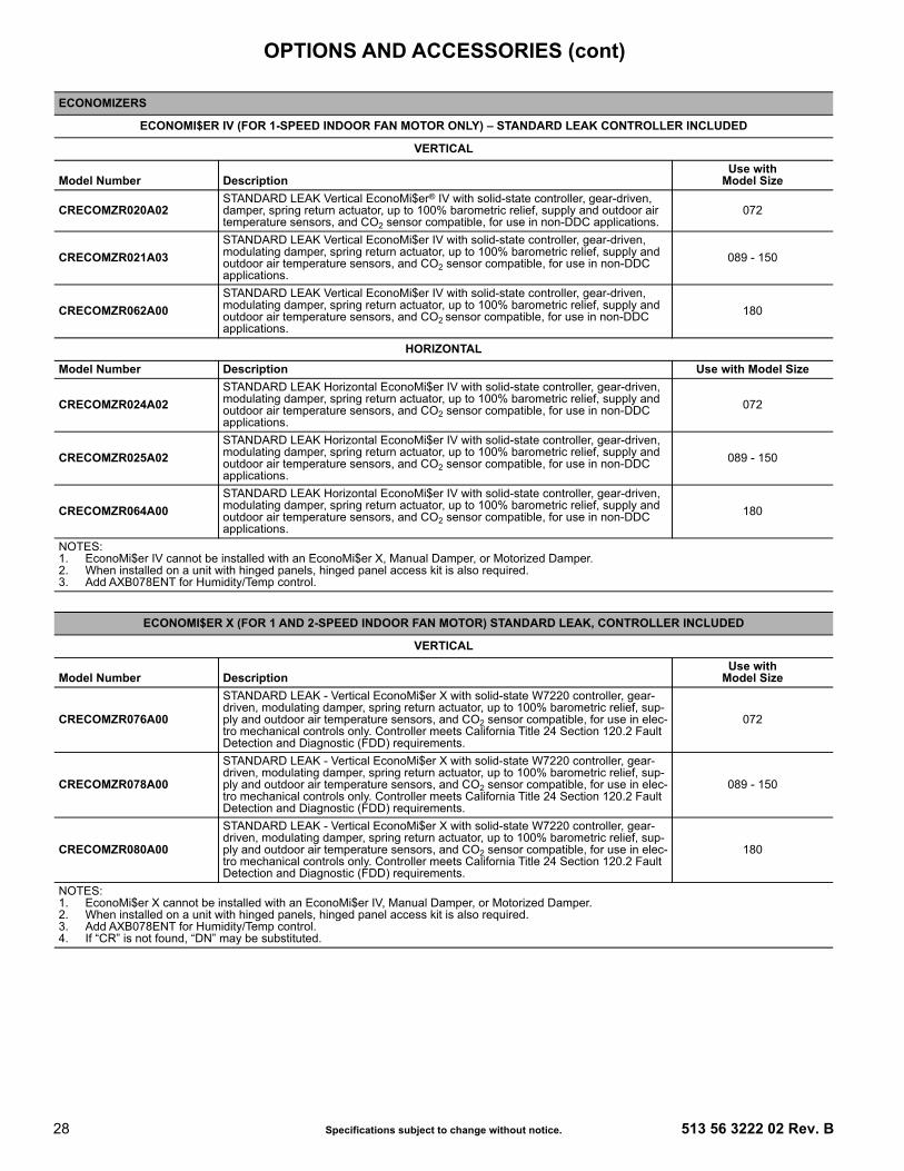
28 Specifications subject to change without notice. 513 56 3222 02 Rev. B
ECONOMIZERS
ECONOMI$ER IV (FOR 1-SPEED INDOOR FAN MOTOR ONLY) – STANDARD LEAK CONTROLLER INCLUDED
VERTICAL
Model Number DescriptionUse with
Model Size
CRECOMZR020A02STANDARD LEAK Vertical EconoMi$er® IV with solid-state controller, gear-driven, damper, spring return actuator, up to 100% barometric relief, supply and outdoor air temperature sensors, and CO2 sensor compatible, for use in non-DDC applications.
072
CRECOMZR021A03STANDARD LEAK Vertical EconoMi$er IV with solid-state controller, gear-driven, modulating damper, spring return actuator, up to 100% barometric relief, supply and outdoor air temperature sensors, and CO2 sensor compatible, for use in non-DDC applications.
089 - 150
CRECOMZR062A00STANDARD LEAK Vertical EconoMi$er IV with solid-state controller, gear-driven, modulating damper, spring return actuator, up to 100% barometric relief, supply and outdoor air temperature sensors, and CO2 sensor compatible, for use in non-DDC applications.
180
HORIZONTALModel Number Description Use with Model Size
CRECOMZR024A02STANDARD LEAK Horizontal EconoMi$er IV with solid-state controller, gear-driven, modulating damper, spring return actuator, up to 100% barometric relief, supply and outdoor air temperature sensors, and CO2 sensor compatible, for use in non-DDC applications.
072
CRECOMZR025A02STANDARD LEAK Horizontal EconoMi$er IV with solid-state controller, gear-driven, modulating damper, spring return actuator, up to 100% barometric relief, supply and outdoor air temperature sensors, and CO2 sensor compatible, for use in non-DDC applications.
089 - 150
CRECOMZR064A00STANDARD LEAK Horizontal EconoMi$er IV with solid-state controller, gear-driven, modulating damper, spring return actuator, up to 100% barometric relief, supply and outdoor air temperature sensors, and CO2 sensor compatible, for use in non-DDC applications.
180
NOTES:1. EconoMi$er IV cannot be installed with an EconoMi$er X, Manual Damper, or Motorized Damper.2. When installed on a unit with hinged panels, hinged panel access kit is also required.3. Add AXB078ENT for Humidity/Temp control.
ECONOMI$ER X (FOR 1 AND 2-SPEED INDOOR FAN MOTOR) STANDARD LEAK, CONTROLLER INCLUDED
VERTICAL
Model Number DescriptionUse with
Model Size
CRECOMZR076A00
STANDARD LEAK - Vertical EconoMi$er X with solid-state W7220 controller, gear-driven, modulating damper, spring return actuator, up to 100% barometric relief, sup-ply and outdoor air temperature sensors, and CO2 sensor compatible, for use in elec-tro mechanical controls only. Controller meets California Title 24 Section 120.2 Fault Detection and Diagnostic (FDD) requirements.
072
CRECOMZR078A00
STANDARD LEAK - Vertical EconoMi$er X with solid-state W7220 controller, gear-driven, modulating damper, spring return actuator, up to 100% barometric relief, sup-ply and outdoor air temperature sensors, and CO2 sensor compatible, for use in elec-tro mechanical controls only. Controller meets California Title 24 Section 120.2 Fault Detection and Diagnostic (FDD) requirements.
089 - 150
CRECOMZR080A00
STANDARD LEAK - Vertical EconoMi$er X with solid-state W7220 controller, gear-driven, modulating damper, spring return actuator, up to 100% barometric relief, sup-ply and outdoor air temperature sensors, and CO2 sensor compatible, for use in elec-tro mechanical controls only. Controller meets California Title 24 Section 120.2 Fault Detection and Diagnostic (FDD) requirements.
180
NOTES:1. EconoMi$er X cannot be installed with an EconoMi$er IV, Manual Damper, or Motorized Damper.2. When installed on a unit with hinged panels, hinged panel access kit is also required.3. Add AXB078ENT for Humidity/Temp control.4. If “CR” is not found, “DN” may be substituted.
OPTIONS AND ACCESSORIES (cont)

513 56 3222 02 Rev. B Specifications subject to change without notice. 29
ECONOMI$ER X (FOR 1 AND 2-SPEED INDOOR FAN MOTOR) STANDARD LEAK, CONTROLLER INCLUDED
HORIZONTALModel Number Description Use with Model Size
CRECOMZR077A00
STANDARD LEAK - Horizontal EconoMi$er® X with solid-state W7220 controller, gear-driven, modulating damper, spring return actuator, up to 100% barometric relief, supply and outdoor air temperature sensors, and CO2 sensor compatible, for use in electro mechanical controls only. Controller meets California title 24 Section 120.2 Fault Detection and Diagnostic (FDD) requirements.
072
CRECOMZR079A00
STANDARD LEAK - Horizontal EconoMi$er X with solid-state W7220 controller, gear-driven, modulating damper, spring return actuator, up to 100% barometric relief, sup-ply and outdoor air temperature sensors, and CO2 sensor compatible, for use in elec-tro mechanical controls only. Controller meets California Title 24 Section 120.2 Fault Detection and Diagnostic (FDD) requirements.
089 - 150
CRECOMZR081A00
STANDARD LEAK - Horizontal EconoMi$er X with solid-state W7220 controller, gear-driven, modulating damper, spring return actuator, up to 100% barometric relief, sup-ply and outdoor air sensors, and CO2 sensor compatible, for use in electro mechani-cal controls only. Controller meets California Title 24 Section 120.2 Fault Detection and Diagnostic (FDD) requirements.
180
NOTES:1. EconoMi$er X cannot be installed with an EconoMi$er IV, Manual Damper, or Motorized Damper.2. When installed on a unit with hinged panels, hinged panel access kit is also required.3. Add AXB078ENT for Humidity/Temp control.
ECONOMI$ER X (FOR 1 AND 2-SPEED INDOOR FAN MOTOR) ULTRA LOW LEAK, CONTROLLER INCLUDED
VERTICAL
Model Number DescriptionUse with
Model Size
CRECOMZR067A00
Ultra LOW LEAK - Vertical EconoMi$er X with solid-state W7220 controller, gear-driven, modulating damper, spring return actuator, up to 100% barometric relief, sup-ply and outdoor air temperature sensors, and CO2 sensor compatible, for use in elec-tro mechanical controls only. Also includes return, outside air, and relief air damper leakage that meets Title 24 section 140.4 and ASHRAE 90.1 requirements. Controller meets California Title 24 Fault Detection and Diagnostic (FDD) requirements.
072
CRECOMZR069A00
Ultra LOW LEAK - Vertical EconoMi$er X with solid-state W7220 controller, gear-driven, modulating damper, spring return actuator, up to 100% barometric relief, sup-ply and outdoor air temperature sensors, and CO2 sensor compatible, for use in elec-tro mechanical controls only. Also includes return, outside air, and relief air damper leakage that meets Title 24 section 140.4 and ASHRAE 90.1 requirements. Controller meets California Title 24 Fault Detection and Diagnostic (FDD) requirements.
089 - 150
CRECOMZR071A00
Ultra LOW LEAK - Vertical EconoMi$er X with solid-state W7220 controller, gear-driven, modulating damper, spring return actuator, up to 100% barometric relief, sup-ply and outdoor air sensors, and CO2 sensor compatible, for use in electro mechani-cal controls only. Also includes return, outside air, and relief air damper leakage that meets Title 24 section 140.4 and ASHRAE 90.1 requirements. Controller meets Cali-fornia Title 24 Fault Detection and Diagnostic (FDD) requirements.
180
NOTES:1. EconoMi$er X cannot be installed with an EconoMi$er IV, Manual Damper or Motorized Damper.2. Currently only available on vertical air flow configuration models. Contact your local MicroMetl account manager 1-800-884-4662 if horizontal
model is required.3. When installed on a unit with hinged panels, hinged panel access kit is also required.4. Add AXB078ENT for Humidity/Temp control.5. If “CR” is not found, “DN” may be substituted.
OPTIONS AND ACCESSORIES (cont)

30 Specifications subject to change without notice. 513 56 3222 02 Rev. B
ACCESSORY KITS FOR UNITS WITH HINGED ACCESS PANELS
VERTICAL
Model Number DescriptionUse with
Model Size
CRPECONV003A00 Vertical accessory kit used with installing a vertical economizer on a unit that has hinged access panels. Includes angle and seal strip. 072
CRPECONV004A00 Vertical accessory kit used with installing a vertical economizer on a unit that has hinged access panels. Includes angle and seal strip. 089 - 150
CRPECONV007B00Vertical and Horizontal accessory kit used with installing a 2-position damper or verti-cal and horizontal economizer on a unit that has hinged access panels. Includes angle and seal strip.
180
HORIZONTAL
Model Number DescriptionUse with
Model Size
CRHNGPNL001A00 Horizontal accessory kit used with installing a vertical economizer on a unit that has hinged access panels. Includes angle and seal strip. 072
CRHNGPNL002A00 Horizontal accessory kit used with installing a vertical economizer on a unit that has hinged access panels. Includes angle and seal strip. 089 - 150
CRHNGPNL003A00Currently in development - please contact application engineering. Hinged filter access door kit for use with horizontal economizer accessory. Replaces door sent with economizer. Includes door panel, angle and seal strip.
180
ECONOMIZER SENSORS
Model Number DescriptionUse with
Model Size
DNTEMPSN002A00 Outdoor or Return Dry Bulb Temperature Sensor used with electro-mechanical control. ECONOMI$ER® IV
DNCBDIOX005A00 CO2 Sensor for use in return airstream. Also includes Aspirator Box required for Duct Mounting. ECONOMI$ER IV and X
DNENTDIF004A00 Return Air Enthalpy Sensor used with electro-mechanical controls, use with AXB078ENT for differential enthalpy control. ECONOMI$ER IV
AXB078ENT Economizer Differential Enthalpy Control Upgrade. ECONOMI$ER IV
CRTEMPSN005A00 Outdoor or return dry bulb temperature sensor used with Honeywell W7220 electro-mechanical control. ECONOMI$ER X
--HH--57AC-081 Enthalpy control for W7220 controller only. (One required for single enthalpy, two required for differential enthalpy) ECONOMI$ER X
NOTES:1. Supply air temperature sensor (SAT and low ambient lockout switch) provided with EconoMi$er IV or EconoMi$er X.2. Currently only available on vertical air flow configuration models. Contact your local MicroMetl account manager 1-800-884-4662 if horizontal
model is required.
ECONOMIZER SENSOR USAGE CHARTDESIRED CONTROLMETHOD
ECONOMI$ER IV1 REQUIRED FIELD-INSTALLED SENSOR(S)
ECONOMI$ER X1 REQUIRED FIELD-INSTALLED SENSOR(S)
Single Dry Bulb Control None. Outside Air dry bulb sensor is factory installed. None. Outside Air dry bulb sensor is factory installed.Single Enthalpy Control (1) AXB078ENT (1) --HH--57AC-081Differential Dry Bulb NA (1) --HH--57AC-081Differential Enthalpy Control (1) AXB078ENT and (1) DNENTDIF004A00 (2) --HH--57AC-081To Add CO2 DCV Controlwith above: Duct Mount (1) DNCBDIOX005A00 (1) DNCBDIOX005A00
--HH--57AC-081Enthalpy control for W7220 controller only. (One
required for single enthalpy, two required for differen-tial enthalpy)
ECONOMI$ER X
1 OAT and SAT sensors included for EconoMi$er IV or EconoMi$er X.
OPTIONS AND ACCESSORIES (cont)
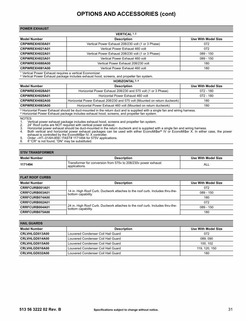
513 56 3222 02 Rev. B Specifications subject to change without notice. 31
POWER EXHAUSTVERTICAL 1, 2
Model Number Description Use With Model SizeCRPWREXH030A01 Vertical Power Exhaust 208/230 volt (1 or 3 Phase) 072CRPWREXH021A01 Vertical Power Exhaust 460 volt 072CRPWREXH022A01 Vertical Power Exhaust 208/230 volt (1 or 3 Phase) 089 - 150CRPWREXH023A01 Vertical Power Exhaust 460 volt 089 - 150CRPWREXH080A00 Vertical Power Exhaust 208/230 volt 180CRPWREXH081A00 Vertical Power Exhaust 460 volt 1801 Vertical Power Exhaust requires a vertical Economizer.2 Vertical Power Exhaust package includes exhaust hood, screens, and propeller fan system.
HORIZONTAL 3, 4
Model Number Description Use With Model SizeCRPWREXH028A01 Horizontal Power Exhaust 208/230 and 575 volt (1 or 3 Phase) 072 - 180CRPWREXH029A01 Horizontal Power Exhaust 460 volt 072 - 180CRPWREXH082A00 Horizontal Power Exhaust 208/230 and 575 volt (Mounted on return ductwork) 180CRPWREXH083A00 Horizontal Power Exhaust 460 volt (Mounted on return ductwork) 1803 Horizontal Power Exhaust should be duct-mounted in the return duct and is supplied with a single fan and wiring harness.4 Horizontal Power Exhaust package includes exhaust hood, screens, and propeller fan system.NOTES:1. Vertical power exhaust package includes exhaust hood, screens and propeller fan system.2. 24” Roof curbs are NOT required with vertical power exhaust.3. Horizontal power exhaust should be duct-mounted in the return ductwork and is supplied with a single fan and wiring harness.4. Both vertical and horizontal power exhaust packages can be used with either EconoMi$er® IV or EconoMi$er X. In either case, the power
exhaust is controlled by the EconoMi$er IV, X controller. 5. Order --HT--01AH-859 / FAST# 1171494 for 575V applications.6. If “CR” is not found, “DN” may be substituted.
575V TRANSFORMERModel Number Description Use With Model Size
1171494 Transformer for conversion from 575v to 208/230v power exhaust applications. ALL
FLAT ROOF CURBSModel Number Description Use With Model SizeCRRFCURB001A01
14 in. High Roof Curb. Ductwork attaches to the roof curb. Includes thru-the-bottom capability.
072CRRFCURB003A01 089 - 150CRRFCURB074A00 180CRRFCURB002A01
24 in. High Roof Curb. Ductwork attaches to the roof curb. Includes thru-the-bottom capability.
072CRRFCURB004A01 089 - 150CRRFCURB075A00 180
HAIL GUARDSModel Number Description Use With Model SizeCRLVHLGD013A00 Louvered Condenser Coil Hail Guard 072CRLVHLGD014A00 Louvered Condenser Coil Hail Guard 089, 090CRLVHLGD015A00 Louvered Condenser Coil Hail Guard 100, 102CRLVHLGD016A00 Louvered Condenser Coil Hail Guard 119, 120, 150CRLVHLGD032A00 Louvered Condenser Coil Hail Guard 180
OPTIONS AND ACCESSORIES (cont)

32 Specifications subject to change without notice. 513 56 3222 02 Rev. B
MANUAL OUTDOOR AIR DAMPERSModel Number Description Use With Model SizeCRMANDPR001A03 25% Open Manual Fresh Air Damper 072CRMANDPR001A02 50% Open Manual Fresh Air Damper 072CRMANDPR002A03 25% Open Manual Fresh Air Damper 089 - 150CRMANDPR002A02 50% Open Manual Fresh Air Damper 089 - 150CRMANDPR011A00 50% Open Manual Fresh Air Damper 180
MOTORIZED OUTDOOR AIR DAMPERSModel Number Description Use With Model SizeCRTWOPOS010A00 Motorized 2 position outdoor air damper (25−100% Outdoor Air) 072CRTWOPOS011A00 Motorized 2 position outdoor air damper (25−100% Outdoor Air) 089 - 150CRTWOPOS014A00 Motorized 2 position outdoor air damper (25−100% Outdoor Air) 180NOTE: EconoMi$er IV, EconoMi$er X, Manual Damper and 2-Position damper are all mutually exclusive and cannot be installed together.
SPECIAL - 180 SIZE SPECIFIC ACCESSORIESModel Number Description Use With Model Size
CRDISBKT001A00Disconnect Switch Bracket - Provides a pre engineered and sized mounting bracket for applications requiring a unit mounted fused disconnect of greater than 100 amps. Bracket assures that no damage will occur to coils when mounting with screws and other fasteners.
180
CRDUCTCV002A00Supply Duct Cover - This supply duct cover is required when field converting the factory standard vertical duct supply to horizontal duct supply configura-tion. One required per unit.
180
THROUGH−THE−BOTTOM/CURB POWER CONNECTIONModel Number Description Use With Model Size
CRBTMPWR001A01Thru-the-bottom electrical connections and thru-the-curb gas connections. Includes a 3/4-inch diameter liquid tight conduit fitting for high voltage power wires.
072
CRBTMPWR002A01Thru-the-bottom electrical connections and thru-the-curb gas connections. Includes a 1-1/4-inch diameter liquid tight conduit fitting for high voltage power wires.
089 - 150
CRBTMPWR003A01 Thru-the-bottom power, control, and gas connections. Includes a 3/4-inchdiameter liquid tight conduit fitting for high voltage power wires. 072
CRBTMPWR004A01 Thru-the-bottom power, control, and gas connections. Includes a 1-1/4-inch diameter liquid tight conduit fitting for high voltage power wires. 089 - 150
CRBTMPWR005A00 Thru-the-bottom power, control, and gas connections. Includes a 1-1/4 inch diameter liquid tight conduit fitting for high voltage power wires.
180CRBTMPWR006A00 Thru-the-bottom power, control, and gas connections. Includes a 1-1/2 inch diameter liquid tight conduit fitting for high voltage power wires.
CRBTMPWR007A00 Thru-the-bottom power, control, and gas connections. Includes a 2 inch diam-eter liquid tight conduit fitting for high voltage power wires
NOTES:1. Manual dampers include hood assembly, bird screen, adjustable damper blade (to allow up to the rated outdoor air %), and bottom panel with
opening.2. Motorized dampers include bottom panel with opening (100% two-position damper includes 30% barometric relief capability), and adjustable
damper (to allow up to the rated outdoor air %)3. Motorized dampers will close on loss of power to the rooftop unit. Manual and motorized dampers are not compatible with a vertical power
exhaust module.
OPTIONS AND ACCESSORIES (cont)

513 56 3222 02 Rev. B Specifications subject to change without notice. 33
CONTROL UPGRADE KITSModel Number Description Use With Model Size
CRDISKIT001A002-Speed VFD display kit provides the field capability to set up points and trou-bleshooting codes on the VFD controller. Kit includes display and cable. If pre-ferred, kit can be used for any associated unit with VFD.
All 2-Speed VFD Controllers
NRTIMEGD001A00Time Guard II - Automatically prevents the compressor from restarting for at least 4 minutes and 45 seconds after shutdown of the compressor. Not required when a commercial thermostat has a minimum 5 min time delay between cooling cycles available. (One required per unit.)
072 - 180
CRSDTEST001A00 Remote keyed attenuator / test / reset station 072 - 180
DNWINSTR001A00 Winter Start Package -- Contains time delay relay for timed bypass of low pressure switch on startup. (One required per refrigerant circuit)1 072 - 180
CRPHASE3001A02 Phase Monitor Control 072 - 180 (3 Phase only)CRPHASE3002A00 Phase Monitor Control 072 - 180 (575V 2 only)CRSTATUS001A00 Fan/Filter Status Switch - Indicator light not included 072 - 1801 If mechanical cooling below 25 degrees ambient is necessary, consider additional low ambient control measures (for example, Economizer or
Motormaster®)2 575V is not available for RAS089 units.
LOW AMBIENT CONTROLS *Model Number Description Use With Model Size
32LT900301 1 Motormaster I Solid-State Variable Speed Motor Controller enables cooling down to –20°F by varying the speed on the condenser fan.
072 - 120208/203-3-60,
575-3-60 5
32LT900611 1 Motormaster I Solid-State Variable Speed Motor Controller enables cooling down to –20°F by varying the speed on the condenser fan.
072 - 120460-3-60
CPLOWAMB001A00Motormaster II Low Ambient Control - Enables cooling system to operate down to 0°F by cycling condenser fan on and off. The control is activated by a temperature sensor. No motor change-out required.
036 - 121208/230-3-60, 460-3-60 4
1171974 2 Motormaster I Compatible Condenser Fan Motor072 - 120
208/230-3-60,575-3-60 5
1171975 2 Motormaster I Compatible Condenser Fan Motor 072 - 120460-3-60
1171807 2 MFD 10072 - 120
08/230-3-60,575-3-60 5
1175708 2 Dual MFD 10 + 10 072 - 120460-3-60
CRLOWAMB030A00 3 Motormaster V Low Ambient Kit. Mechanical cooling operation down to –20°F (–29°C).
150208/230-3-60
CRLOWAMB031A00 3 Motormaster V Low Ambient Kit. Mechanical cooling operation down to –20°F (–29°C).
150460-3-60
CRLOWAMB032A00 3 Motormaster V Low Ambient Kit. Mechanical cooling operation down to –20°F (–29°C).
150575-3-60
CRLOWAMB039A00Motormaster I Low Ambient Kit. Mechanical cooling operation down to –20°F (–29°C). Kit includes 3 motors, Motormaster controller, wiring label, and required wire ties and connectors. DNWINSTR001A00 also required (one per refrigerant circuit).
180208/230-3-60
CRLOWAMB040A00Motormaster I Low Ambient Kit. Mechanical cooling operation down to –20°F (–29°C). Kit includes 3 motors, Motormaster controller, wiring label, and required wire ties and connectors. 575 Volt models also require CRTRX-KIT002A00 plus DNWINSTR001A00 (one per refrigerant circuit).
180460-3-60
CRTRXKIT002A00Motormaster I Low Ambient Control - Transformer Kit. Must be used in con-junction with CRLOWAMB040A00 if used on 575-3-60 volt models. Contains transformer, special mounting bracket designed specifically for this unit, capacitors and wires.
180575-3-60
* See usage tables in kit instructions.1 Requires motor change out. Sizes 072 require one (1) Low Ambient Controller and one (1) compatible condenser fan motor for change-out. Sizes
089-120 require one (1) Low Ambient Controller and two (2) compatible condenser fan motors for change-out. See Motormaster I kit instructions for capacitor replacement information.
2 Available from FAST Parts.3 No motor change is required on these specific models.4 One DNWINSTR001A00 also required per refrigerant circuit.5 575V is not available for RAS089 units.
OPTIONS AND ACCESSORIES (cont)

34 Specifications subject to change without notice. 513 56 3222 02 Rev. B
* 575V is not available for RAS089 units.
* 575V is not available for RAS089 units.
ELECTRIC HEATERSModel Number Voltage Nominal Power (kW) Used With Model SizeCRHEATER101A00 208/230 4.4 072CRHEATER102A00 208/230 6.5 072CRHEATER104B00 208/230 10.5 072CRHEATER105A00 208/230 16.0 072CRHEATER106A00 460 6.0 072CRHEATER108A00 460 11.5 072CRHEATER109A00 460 14.0 072CRHEATER110A00 208/230 16.0 089 - 150CRHEATER111A00 208/230 24.8 089 - 120CRHEATER112A00 208/230 32.0 089 - 150CRHEATER113A00 460 16.5 089 - 150CRHEATER114A00 460 27.8 089 - 150CRHEATER115A00 460 33.0 089 - 150CRHEATER116A00 460 13.9 089 - 150CRHEATER117A00 208/230 10.4 089 - 150CRHEATER118A00 575 17.0 089* - 150CRHEATER119A00 575 34.0 089* - 150CRHEATER288A00 208/230 10.0 180CRHEATER289A00 460 10.0 180CRHEATER290A00 575 10.0 180CRHEATER291A00 208/230 16.5 180CRHEATER292A00 460 16.5 180CRHEATER293A00 575 16.5 180CRHEATER294A00 208/230 33.5 180CRHEATER295A00 460 33.5 180CRHEATER296A00 575 33.5 180
SINGLE POINT WIRING KITSModel Number Voltage Used With Model SizeCRSINGLE037A00 208/230/460-3-60 072CRSINGLE042A00 208/230/460/575-3-60 089, 090CRSINGLE043A00 208/230-3-60 089, 090CRSINGLE044A00 460/575-3-60 089*, 090CRSINGLE045A00 208/230-3-60 089, 090CRSINGLE047A00 208/230/460/575-3-60 100, 102, 119, 120, 150, 180CRSINGLE049A00 208/230-3-60 100, 102, 119, 120, 150, 180CRSINGLE050A00 460/575-3-60 100, 102, 119, 120, 150, 180CRSINGLE051A00 208/230-3-60 100, 102, 119, 120, 150, 180CRSINGLE053A00 208/230-3-60 180CRHEATER296A00 575 180
OPTIONS AND ACCESSORIES (cont)

513 56 3222 02 Rev. B Specifications subject to change without notice. 35
UNIT DIMENSIONAL DRAWING - 072 SIZE UNITS BUILT ON AND AFTER 4/15/2019
DIMENSIONS

36 Specifications subject to change without notice. 513 56 3222 02 Rev. B
UNIT DIMENSIONAL DRAWING - 072 SIZE UNITS BUILT PRIOR TO 4/15/2019
DIMENSIONS (cont)

513 56 3222 02 Rev. B Specifications subject to change without notice. 37
UNIT DIMENSIONAL DRAWING - 072 CORNER WEIGHTS AND CLEARANCES
DIMENSIONS (cont)

38 Specifications subject to change without notice. 513 56 3222 02 Rev. B
UNIT DIMENSIONAL DRAWING - 072 BASE RAIL DETAILS
DIMENSIONS (cont)

513 56 3222 02 Rev. B Specifications subject to change without notice. 39
UNIT DIMENSIONAL DRAWING - 072 THRU-THE-BASE CHARTS
DIMENSIONS (cont)

40 Specifications subject to change without notice. 513 56 3222 02 Rev. B
ROOF CURB DETAILS — 072 SIZE UNIT
EE
7/16
"[1
1]
4 9/
16"
[115
.5]
1/4"
[7.0
]
5' 7
-3/8
"[1
711.
3]
1' 4
-13/
16"
[4
27] I
NSI
DE
1-3/
4"[4
4.4]
2-3/
8"[6
1]
1-3/
4"[4
4.5]
1.00
"[2
5.4]
"A"
1-3/
4"[4
4.4]
21.7
4"[5
52.2
]5.42
"[1
37.7
]11
.96"
[303
.8]
4.96
"[1
26.0
]70
.87"
[180
0.2]
40.6
9"[1
033.
5]
21.8
4"[5
54.7
]
16.0
3"[4
07.2
]
1.75
"[4
4.5]
20.4
1"[5
18.3
]3.
00"
[76.
2]13
.78"
[350
.0]
14.0
0"[3
55.6
]
3.00
"[7
6.2]
15.1
9"[3
85.8
]
32.1
9"[8
17.6
]
3'-1
3/1
6"[9
44.6
]
"A"
1-3/
4"[4
4.5]
CR
BTM
PWR
001A
013/
4" [1
9] N
PT3/
4" [1
9] N
PT1/
2" [1
2.7]
NPT
CR
RFC
UR
B002
A01
CO
NN
ECTO
R P
KG. A
CC
.G
AS C
ON
NEC
TIO
N T
YPE
GAS
FIT
TIN
GPO
WER
WIR
ING
FI
TTIN
GC
ON
TRO
L W
IRIN
G
FITT
ING
ACC
ESSO
RY
CO
NVE
NIE
NC
E O
UTL
ET W
IRIN
G C
ON
NEC
TOR
THR
U T
HE
CU
RB
1/2"
[12.
7] N
PT1/
2" [1
2.7]
NPT
CR
BTM
PWR
003A
01TH
RU
TH
E BO
TTO
M
RO
OF
CU
RB
ACC
ESSO
RY
#A
CR
RFC
UR
B001
A01
14"
[356
]
24"
[610
]
ECN
NO
.AP
P'D
CH
K'D
BYD
ATE
REV
ISIO
N R
ECO
RD
REV
1067
898
--
MM
C04
/22/
13O
VER
ALL
DIM
. 5'-7
3/8
" WAS
5'-7
7/8
; 18G
A M
ATER
IAL
WA
16 G
A.; N
AIL
FIEL
D S
UPP
LIED
WAS
W
ITH
CU
RB
A
DR
AWIN
G R
ELEA
SE L
EVEL
:PR
OD
UC
TIO
NTH
IRD
AN
GLE
PRO
JEC
TIO
N
UN
LESS
OTH
ERW
ISE
SPEC
IFIE
DD
IMEN
SIO
NS
ARE
IN IN
CH
ESTO
LER
ANC
ES O
N:
1 D
EC2
DEC
3 D
ECAN
GM
ATER
IAL
--
--
- - -
AUTH
OR
IZAT
ION
NU
MBE
RTI
TLE
1041
738
CU
RB
ASY,
RO
OF
ENG
INEE
RIN
GM
ANU
FAC
TUR
ING
ENG
INEE
RIN
G R
EQU
IREM
ENTS
--
--
SIZE
DR
AWIN
G N
UM
BER
REV
T-00
5, Y
-002
DR
AFTE
RC
HEC
KER
D48
TC40
0427
BW
EIG
HT:
-M
MC
06/1
7/11
--
SHEE
T 5
OF
5
SUR
FAC
E FI
NIS
HM
FG/P
UR
CH
MO
DEL
(IN
TER
NAL
USE
ON
LY)
NEX
T D
RAW
ING
SCAL
ED
ISTR
IBU
TIO
N
-PU
RC
H-
N/A
MM
C
NO
TES:
1. R
OO
FCU
RB
ACC
ESSO
RY
IS S
HIP
PED
DIS
ASSE
MBL
ED.
2. IN
SULA
TED
PAN
ELS:
25.
4 [1
"] TH
K. P
OLY
UR
ETH
ANE
FOAM
, 44.
5 [1
-3/4
] # D
ENSI
TY.
3. D
IMEN
SIO
NS
IN [
] AR
E IN
MIL
LIM
ETER
S.4.
RO
OFC
UR
B: 1
8 G
AGE
STEE
L.5.
ATT
ACH
DU
CTW
OR
K TO
CU
RB.
(FLA
NG
ES O
F D
UC
T R
EST
ON
CU
RB)
.6.
SER
VIC
E C
LEAR
ANC
E 4
FEET
ON
EAC
H S
IDE.
7.
DIR
ECTI
ON
OF
AIR
FLO
W.
8. C
ON
NEC
TOR
PAC
KAG
E C
RBT
MPW
R00
1A01
IS F
OR
TH
RU
-TH
E-C
UR
B G
AS T
YPE
P
ACKA
GE
CR
BTM
PWR
003A
01 IS
FO
R T
HR
U-T
HE-
BOTT
OM
TYP
E G
AS C
ON
NEC
TIO
NS.
TYPI
CAL
(4) S
IDES
SUPP
LY A
IRR
ETU
RN
AIR
RO
OFI
NG
MAT
ERIA
L(F
IELD
SU
PPLI
ED)
CAN
T ST
RIP
(FIE
LD S
UPP
LIED
)
RO
OFI
NG
FEL
T(F
IELD
SU
PPLI
ED)
CO
UN
TER
FLA
SHIN
G(F
IELD
SU
PPLI
ED)
UN
ITG
ASKE
T(S
UPP
LIED
WIT
H C
UR
B)
RIG
ID IN
SULA
TIO
N(F
IELD
SU
PPLI
ED)
DU
CT
(FIE
LD S
UPP
LIED
)
NAI
L (F
IELD
SU
PPLI
ED)
CER
TIFI
ED D
RAW
ING
VIEW
"B"
CO
RN
ER D
ETAI
L
SEE
VIEW
"B"
RET
UR
N A
IRSU
PPLY
AIR
SUPP
LY A
IRO
PEN
ING
RET
UR
N A
IRO
PEN
ING
GAS
SER
VIC
E PL
ATE
THR
U T
HE
CU
RB
DR
ILL
HO
LE
2"
[50.
8] @
AS
SEM
BLY
(IF
REQ
UIR
ED)
(SEE
NO
TE #
8)
SEE
NO
TE #
2
11 3
/4"[2
98.5
] WID
EIN
SULA
TED
DEC
K PA
NEL
S
8 9/
16"[2
17.5
] WID
EIN
SULA
TED
DEC
K PA
NEL
1/3/
4"[4
4.5]
SCAL
E 0
.250
E-E
SEC
TIO
N
DIMENSIONS (cont)

513 56 3222 02 Rev. B Specifications subject to change without notice. 41
UNIT DIMENSIONAL DRAWING — 089 - 120 SIZE UNIT
RA
S08
9/09
0
RA
S10
0/10
2
RA
S11
9/12
0
DIMENSIONS (cont)

42 Specifications subject to change without notice. 513 56 3222 02 Rev. B
UNIT DIMENSIONAL DRAWING — 089 - 120 SIZE UNIT (cont)
RA
S08
9R
AS
100
RA
S11
9R
AS
090
RA
S10
2R
AS
120
DIMENSIONS (cont)

513 56 3222 02 Rev. B Specifications subject to change without notice. 43
SERVICE CLEARANCE DIMENSIONAL DRAWING — 089 - 120 SIZE UNITS
C
D
AB
NOTE: Unit not designed to have overhead obstruction. Contact Application Engineering for guidance on any application planning overhead obstruction or vertical clearances.
LOC DIMENSION CONDITION
A
48-in. (1219 mm)36-in.(914 mm)18-in. (457 mm)18-in. (457 mm)12-in. (305 mm)
• Unit disconnect is mounted on panel • If dimension B is 12-in. (305 mm)• No disconnect, convenience outlet option • Recommended service clearance (electric screwdriver)• Minimum clearance (use manual ratchet screwdriver)
B36-in. (914 mm)12-in. (305 mm)Special
• Unit has economizer• If dimension A is 36-in. (914 mm)• Check for sources of flue products within 10-ft of unit fresh air intake hood
C 36-in. (914 mm)18-in. (457 mm)
• Side condensate drain is used • Minimum clearance
D 42-in. (1067 mm)36-in. (914 mm)
• Surface behind servicer is grounded (e.g., metal, masonry wall, another unit) • Surface behind servicer is electrically non-conductive (e.g., wood, fiberglass)
DIMENSIONS (cont)

44 Specifications subject to change without notice. 513 56 3222 02 Rev. B
ROOF CURB DETAILS — 089 - 150 SIZE UNIT
7/16
"[1
1]
4 9/
16"
[115
.5]
1/4"
[7.0
]
"A"
1 3/
4"[4
4.5]
1 3/
4"[4
4.4]
20-3
/4"
[513
]IN
SID
E
"A"
81 3
/4"
[207
6.3]
53 1
/2"
[135
8.9]
1 3/
4"[4
4.5]
40 3
/16"
[102
0.8]
2 1/
4"[5
7.2]
26"
[660
.4]
4 3/
16"
[106
.0]
6 3/
64"
[153
.5]
32 9
/16"
[827
.1]
23 1
/16"
[585
.8]
31 1
7/32
"[8
00.9
]1
3/4"
[44.
5]
15 1
3/16
"[4
01.6
]
11.4
2"[2
90.0
]
1 3/
4"[4
4.4]
3"[7
6.2]
2-3/
8"[6
1]
14 3
/4"
[374
.7]
6' 6
-1/4
"[1
987.
5]
1-3
/4"
TYP
[44.
5]
4' 2
"[1
270.
0]
15 1
5/32
[392
.9]
1.00
"[2
5.4]
CR
BTM
PWR
002A
013/
4" [1
9] N
PT1
1/4"
[31.
7] N
PTC
RR
FCU
RB0
04A0
1
CO
NN
ECTO
R P
KG. A
CC
.G
AS C
ON
NEC
TIO
N T
YPE
GAS
FIT
TIN
GPO
WER
WIR
ING
FI
TTIN
GC
ON
TRO
L W
IRIN
G
FITT
ING
ACC
ESSO
RY
CO
NVE
NIE
NC
E O
UTL
ET W
IRIN
G C
ON
NEC
TOR
THR
U T
HE
CU
RB
1/2"
[12.
7] N
PT1/
2" [1
2.7]
NPT
CR
BTM
PWR
004A
01TH
RU
TH
E BO
TTO
M
RO
OF
CU
RB
ACC
ESSO
RY
#A
CR
RFC
UR
B003
A01
14"
[356
]
24"
[610
]
ECN
NO
.AP
P'D
CH
K'D
BYD
ATE
REV
ISIO
N R
ECO
RD
REV
1067
898
CM
M-
-4/
22/1
36'
61/
4" W
AS 6
' 7 1
/6",
4'2'
WAS
4' 2
13/
16";
18 G
A W
AS 1
6 G
A.; 1
5 13
/16"
WAS
15
15/1
6"; N
AIL
FIEL
D S
UPP
LIED
WAS
WIT
H C
UR
BC
DR
AWIN
G R
ELEA
SE L
EVEL
:PR
OD
UC
TIO
NTH
IRD
AN
GLE
PRO
JEC
TIO
N
UN
LESS
OTH
ERW
ISE
SPEC
IFIE
DD
IMEN
SIO
NS
ARE
IN IN
CH
ESTO
LER
ANC
ES O
N:
THIS
DO
CU
MEN
T AN
D T
HE
INFO
RM
ATIO
N C
ON
TAIN
ED T
HER
EIN
IS P
RO
PRIE
TAR
Y TO
CAR
RIE
R C
OR
POR
ATIO
N A
ND
SH
ALL
NO
TBE
USE
D O
R D
ISC
LOSE
D T
O O
THER
S, IN
WH
OLE
OR
IN P
ART,
WIT
HO
UT
THE
WR
ITTE
N A
UTH
OR
IZAT
ION
OF
CAR
RIE
R C
OR
POR
ATIO
N.
1 D
EC2
DEC
3 D
ECAN
GM
ATER
IAL
--
--
- - -
AUTH
OR
IZAT
ION
NU
MBE
RTI
TLE
1029
120
CU
RB
ASY,
RO
OF
ENG
INEE
RIN
GM
ANU
FAC
TUR
ING
ENG
INEE
RIN
G R
EQU
IREM
ENTS
--
--
SIZE
DR
AWIN
G N
UM
BER
REV
T-00
5, Y
-002
DR
AFTE
RC
HEC
KER
D50
HJ4
0501
2C
WEI
GH
T:-
MM
C12
/16/
09-
-SH
EET
5 O
F 5
SUR
FAC
E FI
NIS
HM
FG/P
UR
CH
MO
DEL
(IN
TER
NAL
USE
ON
LY)
NEX
T D
RAW
ING
SCAL
ED
ISTR
IBU
TIO
N
-PU
RC
H-
N/A
-
NO
TES:
1. R
OO
FCU
RB
ACC
ESSO
RY
IS S
HIP
PED
DIS
ASSE
MBL
ED.
2. IN
SULA
TED
PAN
ELS:
25.
4 [1
"] TH
K. P
OLY
UR
ETH
ANE
FOAM
, 44.
5 [1
-3/4
] # D
ENSI
TY.
3. D
IMEN
SIO
NS
IN [
] AR
E IN
MIL
LIM
ETER
S.4.
RO
OFC
UR
B: 1
8 G
AGE
STEE
L.5.
ATT
ACH
DU
CTW
OR
K TO
CU
RB.
(FLA
NG
ES O
F D
UC
T R
EST
ON
CU
RB)
.6.
SER
VIC
E C
LEAR
ANC
E 4
FEET
ON
EAC
H S
IDE.
7.
DIR
ECTI
ON
OF
AIR
FLO
W.
8. C
ON
NEC
TOR
PAC
KAG
E C
RBT
MPW
R00
2A01
IS F
OR
TH
RU
-TH
E-C
UR
B G
AS T
YPE
PA
CKA
GE
CR
BTM
PWR
004A
01 IS
FO
R T
HR
U-T
HE-
BOTT
OM
TYP
E G
AS C
ON
NEC
TIO
NS.
TYPI
CAL
(4) S
IDES
SUPP
LY A
IRR
ETU
RN
AIR
RO
OFI
NG
MAT
ERIA
L(F
IELD
SU
PPLI
ED)
CAN
T ST
RIP
(FIE
LD S
UPP
LIED
)
RO
OFI
NG
FEL
T(F
IELD
SU
PPLI
ED)
CO
UN
TER
FLA
SHIN
G(F
IELD
SU
PPLI
ED)
UN
ITG
ASKE
T(S
UPP
LIED
WIT
H C
UR
B)
RIG
ID IN
SULA
TIO
N(F
IELD
SU
PPLI
ED)
DU
CT
(FIE
LD S
UPP
LIED
)
NAI
L (F
IELD
SU
PPLI
ED)
CER
TIFI
ED D
RAW
ING
VIEW
"B"
CO
RN
ER D
ETAI
L
SEC
TIO
N T
HR
U S
IDE
SE
E V
IEW
"B
"
GAS
SER
VIC
E PL
ATE
THR
U T
HE
CU
RB
DR
ILL
HO
LE
2" [5
0.8]
@
ASSE
MBL
Y (IF
R
EQU
IRED
) (S
EE N
OTE
#8)
SEE
NO
TE #
2
12-1
/2" [
317.
5] W
IDE
INSU
LATE
D D
ECK
PAN
ELS
9-15
/16"
[252
.4] W
IDE
INSU
LATE
D D
ECK
PAN
EL
SUPP
LY A
IRR
ETU
RN
AIR
SUPP
LY A
IRO
PEN
ING
RET
UR
N A
IRO
PEN
ING
DIMENSIONS (cont)

513 56 3222 02 Rev. B Specifications subject to change without notice. 45
UNIT DIMENSIONAL DRAWING — 150 SIZE UNIT
RAS
150
DIMENSIONS (cont)

46 Specifications subject to change without notice. 513 56 3222 02 Rev. B
UNIT DIMENSIONAL DRAWING — 150 SIZE UNIT (cont)
RAS
150
DIMENSIONS (cont)

513 56 3222 02 Rev. B Specifications subject to change without notice. 47
SERVICE CLEARANCE DIMENSIONAL DRAWING — 150 SIZE UNIT
NOTE: Unit not designed to have overhead obstruction. Contact Application Engineering for guidance on any application planning overhead obstruction or vertical clearances.
LOC DIMENSION CONDITION
A48-in. (1219 mm)18-in. (457 mm)18-in. (457 mm)12-in. (305 mm)
• Unit disconnect is mounted on panel • No disconnect, convenience outlet option • Recommended service clearance • Minimum clearance
B42-in. (1067 mm)36-in. (914 mm)Special
• Surface behind servicer is grounded (e.g., metal, masonry wall)• Surface behind servicer is electrically non-conductive (e.g., wood, fiberglass) • Check for sources of flue products within 10-ft of unit fresh air intake hood
C 36-in. (914 mm)18-in. (457 mm)
• Side condensate drain is used • Minimum clearance
D 42-in. (1067 mm)36-in. (914 mm)
• Surface behind servicer is grounded (e.g., metal, masonry wall, another unit) • Surface behind servicer is electrically non-conductive (e.g., wood, fiberglass)
C
BA
D
DIMENSIONS (cont)

48 Specifications subject to change without notice. 513 56 3222 02 Rev. B
UNIT DIMENSIONAL DRAWING — 180 SIZE UNIT
DIMENSIONS (cont)
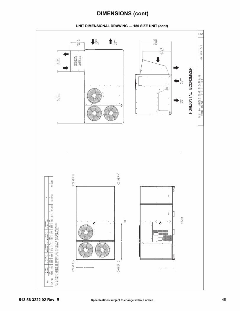
513 56 3222 02 Rev. B Specifications subject to change without notice. 49
UNIT DIMENSIONAL DRAWING — 180 SIZE UNIT (cont)
DIMENSIONS (cont)

50 Specifications subject to change without notice. 513 56 3222 02 Rev. B
SERVICE CLEARANCE DIMENSIONAL DRAWING — 180 SIZE UNIT
NOTE: Unit not designed to have overhead obstruction. Contact Application Engineering for guidance on any application planning overhead obstruction or vertical clearances.
LOC DIMENSION CONDITION
A48-in. (1219 mm)18-in. (457 mm)18-in. (457 mm)12-in. (305 mm)
• Unit disconnect is mounted on panel • No disconnect, convenience outlet option • Recommended service clearance • Minimum clearance
B42-in. (1067 mm)36-in. (914 mm)Special
• Surface behind servicer is grounded (e.g., metal, masonry wall)• Surface behind servicer is electrically non-conductive (e.g., wood, fiberglass) • Check for sources of flue products within 10-ft of unit fresh air intake hood
C 36-in. (914 mm)18-in. (457 mm)
• Side condensate drain is used • Minimum clearance
D48-in. (1219 mm)42-in. (1067 mm)36-in. (914 mm)Special
• No flue discharge accessory installed, surface is combustible material • Surface behind servicer is grounded (e.g., metal, masonry wall, another unit) • Surface behind servicer is electrically non-conductive (e.g., wood, fiberglass)• Check for adjacent units or building fresh air intakes within 10-ft of this unit’s flue outlet
C
BA
D
DIMENSIONS (cont)
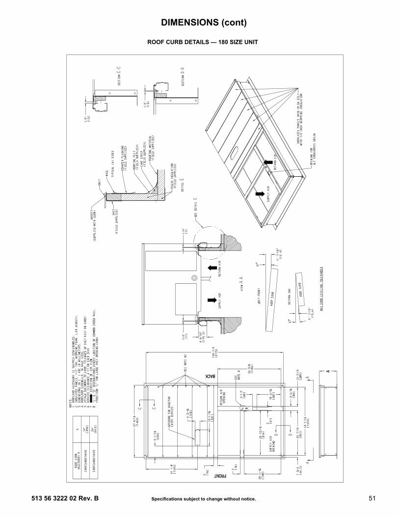
513 56 3222 02 Rev. B Specifications subject to change without notice. 51
ROOF CURB DETAILS — 180 SIZE UNIT
DIMENSIONS (cont)
52 Specifications subject to change without notice. 513 56 3222 02 Rev. B
Min operating ambient temp (cooling)In mechanical cooling mode, your RAS rooftop unit cansafely operate down to an outdoor ambient temperatureof 40°F (4°C) and 25°F (–4°C), with an accessory win-ter start kit. It is possible to provide cooling at lower out-door ambient temperatures by using less outside air,economizers, and/or accessory low ambient kits.
Max operating ambient temp (cooling)The maximum operating ambient temperature for cool-ing mode is 115°F (46°C). While cooling operationabove 115°F (46°C) may be possible, it could causeeither a reduction in performance, reliability, or a protec-tive action by the unit’s internal safety devices.
Min and max airflow (cooling mode)To maintain safe and reliable operation of your rooftop,operate within the cooling airflow limits. Operating abovethe max may cause blow-off, undesired airflow noise, orairflow related problems with the rooftop unit. Operatingbelow the min may cause problems with coil freeze-up.
Heating-to-cooling changeoverYour unit will automatically change from heating to cool-ing mode when using a thermostat with an auto-change-over feature.
AirflowAll units are draw-through in cooling mode and blow-through in heating mode.
Outdoor air application strategies Economizers reduce operating expenses and compres-sor run time by providing a free source of cooling and ameans of ventilation to match application changingneeds. In fact, they should be considered for most appli-cations. Also, consider the various economizer controlmethods and their benefits, as well as sensors required toaccomplish your application goals. Please contact yourlocal representative for assistance.
Motor limits, brake horsepower (BHP)Due to ICP’s internal unit design, air path, and speciallydesigned motors, the full horsepower (maximum continu-ous BHP) band, as listed in the Physical Data tables, canbe used with the utmost confidence. There is no need forextra safety factors, as the motors are designed and rig-orously tested to use the entire, listed BHP range withouteither nuisance tripping or premature motor failure.
Sizing a rooftopBigger isn’t necessarily better. While an air conditionerneeds to have enough capacity to meet the design loads,it doesn’t need excess capacity. In fact, excess capacitytypically results in very poor part load performance andhumidity control.Using higher design temperatures than ASHRAE recom-mends for your location, adding “safety factors” to the cal-culated load, are all signs of oversizing air conditioners.Oversizing the air conditioner leads to poor humidity con-trol, reduced efficiency, higher utility bills, larger indoortemperature swings, excessive noise, and increasedwear and tear on the air conditioner.
Rather than oversizing an air conditioner, engineersshould “right-size” or even slightly undersize air condi-tioners. Correctly sizing an air conditioner controls humid-ity better; promotes efficiency; reduces utility bills;extends equipment life, and maintains even, comfortabletemperatures. Please contact your local ICP representa-tive for assistance.
Low ambient applicationsThe optional economizer can adequately cool your spaceby bringing in fresh, cool outside air. In fact, when soequipped, accessory low-ambient kit may not be neces-sary. In low ambient conditions, unless the outdoor air isexcessively humid or contaminated, economizer-based“free cooling” is the preferred less costly and energy con-scious method. In low ambient applications where out-side air might not be desired (such as contaminated orexcessively humid outdoor environments), your RASrooftop can operate to ambient temperatures down to–20°F (–29°C) using the recommended accessoryMotormaster® low ambient controller or down to 25°F(–4°C) with the field-installed Winter Start Package.
Winter startThe winter start kit extends the low ambient limit of yourrooftop to 25°F (–4°C). The kit bypasses the low pressureswitch, preventing nuisance tripping of the low pressureswitch. Other low ambient precautions may still be prudent.
2-speed indoor fan motor systemThe 2-speed indoor fan motor system has soft start capa-bilities to slowly ramp up the fan speeds, thus eliminatingany high inrush air volume during initial start-up. It alsohas internal over current protection for the fan motor anda field-installed display kit that allows adjustment and indepth diagnostics if required.The 2-speed fan motor system is factory preprogrammedand tested and requires no field adjustment to set up. Theunit fan performance static pressure and cfm can be eas-ily adjusted using the traditional means of belt drive pulleyadjustments.This 2-speed indoor fan motor system is available onmodels with 2-circuit/2-stage cooling (090, 102, 120, 150,180 sizes) and 1-circuit/1-stage cooling (072 size). Oper-ation with electro-mechanical controls. Both space sen-sor and conventional thermostats controls can be used toprovide accurate control in any application.NOTE: The 2-speed indoor fan motor system is not avail-able on sizes 089, 100 or 119.NOTE: When using a 2-position or manual damper withthe 2-speed indoor fan motor system, the damper willeither over-ventilate or under-ventilate during certainmodes of operation. Be aware the effects that ventilationrate has on leaving air temperatures. This becomes morenoticeable in extreme temperatures (heating and cool-ing), since the unit is now treating a higher volume of out-door air. In these scenarios, there are greateradvantages of using an EconoMi$er®X or 3-PositionDamper.
APPLICATION DATA

513 56 3222 02 Rev. B Specifications subject to change without notice. 53
RAS 2-SPEED INDOOR FAN MOTOR SYSTEM - VARIABLE FREQUENCY DRIVE (VFD) HP RATING
Application/selection option Selection software saves time by performing many of thesteps above. Contact your sales representative forassistance.
MODELSIZE STATIC OPTION VOLTAGE VFD HP
072
STD208/230 3.0
460 3.0575 3.0
MED208/230 3.0
460 3.0575 5.0
HIGH208/230 3.0
460 5.0575 5.0
090
STD208/230 3.0
460 3.0575 3.0
MED208/230 3.0
460 3.0575 5.0
HIGH208/230 7.5
460 7.5575 7.5
102
STD208/230 3.0
460 3.0575 3.0
MED208/230 3.0
460 3.0575 3.0
HIGH208/230 5.0
460 5.0575 5.0
120
STD208/230 3.0
460 3.0575 3.0
MED208/230 5.0
460 5.0575 5.0
HIGH208/230 7.5
460 7.5575 7.5
150
STD208/230 3.0
460 3.0575 5.0
MED208/230 5.0
460 5.0575 5.0
HIGH208/230 7.5
460 7.5575 7.5
180
STD208/230 3.0
460 3.0575 5.0
MED208/230 5.0
460 5.0575 5.0
HIGH208/230 7.5
460 7.5575 7.5
APPLICATION DATA (cont)

54 Specifications subject to change without notice. 513 56 3222 02 Rev. B
STATIC PRESSURE ADDERS (in. wg) — FACTORY OPTIONS AND/OR ACCESSORIES
Hot Gas Re-Heat Coil
6 TONSCFM 1000 1250 1500 1750 2000 2250 2500 2750 30006 Tons1-Circuit/1-Stage Cooling
— — — 0.112 0.125 0.161 0.19 0.22 0.25
7.5 - 12.5 TONSCFM 2250 2500 2750 3000 3250 3500 3750 4000 4250 4500 4750 5000 5250 5500 5750 60007.5 Tons2-Circuit/2-Stage Cooling
0.12 0.14 0.16 0.19 0.21 0.23 0.26 — — — — — — — — —
8.5 Tons2-Circuit/2-Stage Cooling
— 0.11 0.12 0.13 0.15 0.17 0.18 0.20 0.22 — — — — — — —
10 Tons2-Circuit/2-Stage Cooling
— — — 0.13 0.15 0.17 0.18 0.20 0.22 0.24 0.26 0.28 — — — —
12.5 Tons2-Circuit/2-Stage Cooling
— — — — — 0.17 0.18 0.20 0.22 0.24 0.26 0.28 0.31 0.33 0.36 0.39
15 TONSCFM 4000 4250 4500 4750 5000 5250 5500 5750 6000 6250 6500 6750 7000 725015 Tons2-Circuit/2-Stage Cooling
0.06 0.07 0.07 0.08 0.08 0.09 0.10 0.10 0.11 0.12 0.12 0.13 0.14 0.15
PERFORMANCE DATA

513 56 3222 02 Rev. B Specifications subject to change without notice. 55
ECONOMIZER, BAROMETRIC RELIEF AND PE PERFORMANCE — VERTICAL APPLICATION
0
500
1000
1500
2000
2500
3000
0.0 0.1 0.2
RE
TU
RN
AIR
FLO
W (
CFM
)
RETURN DUCT STATIC PRESSURE DROP (in. wg)
VERTICAL ECONOMIZER
6 TON
Return air pressure drop — vertical 6 tons
0
500
1000
1500
2000
2500
0 0.05 0.1 0.15 0.2 0.25 0.3
RETURN DUCT STATIC PRESSURE (in. wg)
RE
LIE
F FL
OW
(CFM
)
6 Ton
7½ - 12½ Ton
Vertical Economizers
Barometric relief flow capacity — vertical 6 to 121/2 tons
0
1000
2000
3000
4000
5000
6000
0.0 0.1 0.2 0.3 0.4 0.5
RE
TU
RN
AIR
FLO
W (
CFM
)
VERTICAL ECONOMIZER
RETURN DUCT STATIC PRESSURE DROP (in. wg)7.5 - 12.5 TON
Return air pressure drop — vertical 71/2 to 121/2 tons
0
500
1000
1500
2000
2500
0 0.05 0.1 0.15 0.2 0.25 0.3
RE
LIE
F FL
OW
(CFM
)
RETURN DUCT STATIC PRESSURE (in. wg)
15 -Ton
Vertical Economizers
Barometric relief flow capacity - vertical 15 tons
2,800
3,300
3,800
4,300
4,800
5,300
5,800
6,300
6,800
7,300
0.01 0.02 0.03 0.04 0.05 0.06 0.07 0.08
RE
TU
RN
AIR
LO
W (
CE
M)
RETURN DUCT STATIC PRESSURE DROP (in. wg)
VERTICAL ECONOMIZER STATIC PRESSURE ADDER
Return air pressure drop - vertical 15 tons
0
1000
2000
3000
4000
5000
0 0.1 0.2 0.3 0.4 0.5
RETURN DUCT STATIC PRESSURE (in. wg)
EXH
AU
ST A
IRFL
OW
(cfm
)
Vertical Power Exhaust
6 Ton7.5 - 15 Ton
Vertical power exhaust performance
All data for both standard and ultra low leak models, where available.
PERFORMANCE DATA (cont)

56 Specifications subject to change without notice. 513 56 3222 02 Rev. B
ECONOMIZER, BAROMETRIC RELIEF AND PE PERFORMANCE — HORIZONTAL APPLICATION
0
500
1000
1500
2000
2500
3000
0.0 0.1 0.2
RE
TU
RN
AIR
FLO
W (
CFM
)
RETURN DUCT STATIC PRESSURE DROP (in. wg)
HORIZONTAL ECONOMIZER
6 TON
Return air pressure drop — horizontal 6 tons
2,800
3,300
3,800
4,300
4,800
5,300
5,800
6,300
6,800
7,300
0.05 0.15 0.25 0.35 0.45
RE
TU
RN
AIR
LO
W (
CFM
)
RETURN DUCT STATIC PRESSURE DROP (in. wg)
HORIZONTAL ECONOMIZER STATIC PRESSURE ADDER
Return air pressure drop - horizontal 15 ton
0
1000
2000
3000
4000
5000
6000
0.0 0.1 0.2 0.3 0.4 0.5 0.6
RE
TU
RN
AIR
FLO
W (
CFM
)
HORIZONTAL ECONOMIZER
RETURN DUCT STATIC PRESSURE DROP (in. wg)7.5 - 12.5 TON
Return air pressure drop — horizontal 71/2 to 121/2 tons
Barometric relief flow capacity — horizontal 6 to 121/2 tons
0
500
1000
1500
2000
2500
0 0.05 0.1 0.15 0.2 0.25 0.3
RETURN DUCT STATIC PRESSURE (in. wg)
RE
LIE
F FL
OW
(CFM
)
6 Ton
7½ - 12½ Ton
Horizontal Economizers
0
500
1000
1500
2000
2500
0 0.05 0.1 0.15 0.2 0.25 0.3
RE
LIE
F FL
OW
(CFM
)
RETURN DUCT STATIC PRESSURE (in. wg)
15 -Ton
Horizontal Economizers
Barometric relief flow capacity — horizontal 15 tons
0
500
1000
1500
2000
2500
0 0.1 0.2 0.3 0.4 0.5
EXH
AU
ST A
IRFL
OW
(cfm
)
RETURN DUCT STATIC PRESSURE (in. wg)
Horizontal Power Exhaust
6 - 15 TON
Horizontal power exhaust performance
All data for both standard and ultra low leak models, where available.
PERFORMANCE DATA (cont)

513 56 3222 02 Rev. B Specifications subject to change without notice. 57
GENERAL FAN PERFORMANCE NOTES1. Interpolation is permissible. Do not extrapolate.2. External static pressure is the static pressure difference between the return duct and the supply duct plus the static
pressure caused by any factory-installed options (FIOPs) or accessories.3. Tabular data accounts for pressure loss due to clean filters, unit casing, and wet coils. Factory options and accesso-
ries may add static pressure losses. Selection software is available, through your salesperson, to help you selectthe best motor/drive combination for your application.
4. The Fan Performance tables offer motor/drive recommendations. In cases when two motor/drive combinationswould work, the lower horsepower option is recommended.
5. For information on the electrical properties of RAS motors, please see the Electrical information section of thisbook.
6. For more information on the performance limits of ICP motors, see the application data section of this book.7. The EPACT (Energy Policy Act of 1992) regulates energy requirements for specific types of indoor fan motors.
Motors regulated by EPACT include any general purpose, T-frame (three-digit, 143 and larger), single-speed,foot mounted, polyphase, squirrel cage induction motors of NEMA (National Electrical Manufacturers Association)design A and B, manufactured for use in the United States. Ranging from 1 to 200 Hp, these continuous-duty motorsoperate on 230 and 460 volt, 60 Hz power. If a motor does not fit into these specifications, the motor does nothave to be replaced by an EPACT compliant energy efficient motor. Variable speed motors are exempt from EPACTcompliance requirements. Therefore, the indoor fan motors for RAS072-180 units are exempt from these require-ments.
PERFORMANCE DATA (cont)

58 Specifications subject to change without notice. 513 56 3222 02 Rev. B
PULLEY ADJUSTMENT
RASUNIT
MOTOR/DRIVE COMBO
MOTOR PULLEY TURNS OPEN (RPM)0.0 0.5 1.0 1.5 2.0 2.5 3.0 3.5 4.0 4.5 5.0
072
Standard Static 1457 1419 1380 1342 1303 1265 1227 1188 1150 1111 1073
Medium Static 1518 1484 1449 1415 1380 1346 1311 1277 1242 1208 1173
High Static 1550 1542 1535 1527 1520 1512 1504 1497 1489 1482 1474
089/090
Standard Static 747 721 695 670 644 618 592 566 541 515 489
Medium Static 949 927 906 884 863 841 819 798 776 755 733
High Static*
* High static option not available on RAS089 units.NOTE: Do not adjust pulley further than 5 turns open.
1102 1083 1063 1044 1025 1006 986 967 948 928 909
100/102
Standard Static 733 712 690 669 647 626 604 583 561 540 518
Medium Static 936 911 887 862 838 813 788 764 739 715 690
High Static 1084 1059 1035 1010 986 961 936 912 887 863 838
119/120
Standard Static 838 813 789 764 739 715 690 665 640 616 591
Medium Static 1084 1059 1035 1010 986 961 936 912 887 863 838
High Static 1240 1218 1196 1175 1153 1131 1109 1087 1066 1044 1022
150
Standard Static 843 824 805 786 767 748 728 709 690 671 652
Medium Static 1084 1059 1035 1010 986 961 936 912 887 863 838
High Static 1240 1218 1196 1175 1153 1131 1109 1087 1066 1044 1022
180
Standard Static 676 659 642 625 608 592 575 558 541 524 507
Medium Static 851 829 806 784 761 739 717 694 672 649 627
High Static 955 937 919 901 883 866 848 830 812 794 776
— Factory settings
PERFORMANCE DATA (cont)
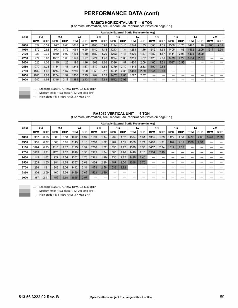
513 56 3222 02 Rev. B Specifications subject to change without notice. 59
RAS072 HORIZONTAL UNIT — 6 TON (For more information, see General Fan Performance Notes on page 57.)
RAS072 VERTICAL UNIT — 6 TON (For more information, see General Fan Performance Notes on page 57.)
CFMAvailable External Static Pressure (in. wg)
0.2 0.4 0.6 0.8 1.0 1.2 1.4 1.6 1.8 2.0RPM BHP RPM BHP RPM BHP RPM BHP RPM BHP RPM BHP RPM BHP RPM BHP RPM BHP RPM BHP
1800 822 0.51 927 0.66 1018 0.82 1100 0.98 1174 1.15 1244 1.33 1308 1.51 1369 1.70 1427 1.90 1483 2.101950 872 0.62 973 0.79 1061 0.95 1140 1.13 1213 1.31 1281 1.49 1345 1.68 1405 1.88 1462 2.09 1517 2.302100 923 0.75 1019 0.92 1104 1.10 1182 1.29 1253 1.48 1320 1.67 1382 1.87 1441 2.08 1498 2.29 — —2250 974 0.90 1067 1.08 1149 1.27 1224 1.46 1294 1.66 1359 1.87 1420 2.08 1479 2.29 1534 2.51 — —2400 1026 1.06 1115 1.26 1195 1.46 1268 1.66 1336 1.87 1400 2.09 1460 2.31 1517 2.53 — — — —2550 1079 1.25 1164 1.46 1241 1.67 1312 1.88 1379 2.10 1441 2.33 1500 2.55 — — — — — —2700 1132 1.46 1214 1.67 1289 1.90 1358 2.12 1422 2.35 1483 2.59 1541 2.83 — — — — — —2850 1186 1.69 1264 1.92 1336 2.15 1404 2.39 1467 2.63 1527 2.87 — — — — — — — —3000 1240 1.94 1315 2.18 1385 2.43 1451 2.68 1512 2.93 — — — — — — — — — —
— Standard static 1073-1457 RPM, 2.4 Max BHP— Medium static 1173-1518 RPM, 2.9 Max BHP— High static 1474-1550 RPM, 3.7 Max BHP
CFMAvailable External Static Pressure (in. wg)
0.2 0.4 0.6 0.8 1.0 1.2 1.4 1.6 1.8 2.0RPM BHP RPM BHP RPM BHP RPM BHP RPM BHP RPM BHP RPM BHP RPM BHP RPM BHP RPM BHP
1800 907 0.63 1006 0.80 1092 0.97 1169 1.14 1239 1.32 1304 1.51 1365 1.69 1422 1.88 1477 2.08 1528 2.28
1950 965 0.77 1060 0.95 1143 1.13 1218 1.32 1287 1.51 1350 1.71 1410 1.91 1467 2.11 1520 2.31 — —
2100 1024 0.93 1115 1.12 1195 1.32 1268 1.52 1335 1.72 1398 1.93 1457 2.14 1512 2.35 — — — —
2250 1083 1.11 1170 1.32 1248 1.53 1319 1.74 1385 1.96 1446 2.18 1504 2.40 — — — — — —
2400 1143 1.32 1227 1.54 1302 1.76 1371 1.99 1435 2.22 1496 2.45 — — — — — — — —
2550 1203 1.55 1284 1.78 1357 2.02 1424 2.26 1487 2.50 1546 2.75 — — — — — — — —
2700 1264 1.81 1342 2.06 1412 2.31 1478 2.56 1539 2.82 — — — — — — — — — —
2850 1326 2.09 1400 2.36 1469 2.62 1532 2.89 — — — — — — — — — — — —
3000 1387 2.41 1459 2.69 1525 2.97 — — — — — — — — — — — — — —
— Standard static 1073-1457 RPM, 2.4 Max BHP— Medium static 1173-1518 RPM, 2.9 Max BHP— High static 1474-1550 RPM, 3.7 Max BHP
PERFORMANCE DATA (cont)

60 Specifications subject to change without notice. 513 56 3222 02 Rev. B
RAS089/090 HORIZONTAL UNIT — 7.5 TON(For more information, see General Fan Performance Notes on page 57.)
RAS089/090 VERTICAL UNIT — 7.5 TON(For more information, see General Fan Performance Notes on page 57.)
CFMAvailable External Static Pressure (in. wg)
0.2 0.4 0.6 0.8 1.0 1.2 1.4 1.6 1.8 2.0RPM BHP RPM BHP RPM BHP RPM BHP RPM BHP RPM BHP RPM BHP RPM BHP RPM BHP RPM BHP
2250 465 0.43 555 0.64 629 0.86 694 1.10 753 1.34 806 1.60 856 1.87 903 2.15 947 2.45 988 2.75
2438 488 0.51 575 0.73 648 0.97 712 1.21 769 1.47 822 1.74 872 2.03 918 2.32 961 2.62 1003 2.93
2625 510 0.60 595 0.84 666 1.09 729 1.34 786 1.62 839 1.90 887 2.19 933 2.49 977 2.81 1018 3.13
2813 533 0.70 616 0.95 686 1.22 748 1.49 804 1.77 856 2.06 904 2.37 949 2.68 992 3.01 1033 3.34
3000 557 0.82 637 1.08 705 1.36 766 1.64 822 1.94 873 2.24 921 2.56 966 2.89 1008 3.22 1049 3.56
3188 581 0.94 659 1.23 726 1.51 785 1.81 840 2.12 891 2.44 938 2.77 982 3.10 1025 3.45 1065 3.81
3375 606 1.08 681 1.38 746 1.68 805 2.00 859 2.32 909 2.65 955 2.99 1000 3.34 1041 3.70 1081 4.06
3563 630 1.24 703 1.55 767 1.87 825 2.20 878 2.53 927 2.88 973 3.23 1017 3.59 1059 3.96 1098 4.34
3750 655 1.41 726 1.74 789 2.07 845 2.41 897 2.76 946 3.12 992 3.48 1035 3.86 1076 4.24 1115 4.63
— Standard static 489-747 RPM, 1.7 Max BHP— Medium static 733-949 RPM, 2.9 Max BHP— High static 909-1102 RPM, 4.7 Max BHP
BOLD — Indicated field-supplied drive.
CFMAvailable External Static Pressure (in. wg)
0.2 0.4 0.6 0.8 1.0 1.2 1.4 1.6 1.8 2.0RPM BHP RPM BHP RPM BHP RPM BHP RPM BHP RPM BHP RPM BHP RPM BHP RPM BHP RPM BHP
2250 511 0.53 591 0.73 660 0.95 722 1.19 779 1.44 832 1.71 882 1.99 928 2.29 973 2.59 1015 2.92
2438 540 0.64 616 0.85 683 1.08 743 1.33 799 1.59 851 1.87 899 2.16 945 2.46 989 2.78 1031 3.11
2625 569 0.76 642 0.99 706 1.23 765 1.49 819 1.76 870 2.04 918 2.34 963 2.66 1006 2.98 1048 3.32
2813 599 0.90 669 1.14 731 1.39 788 1.66 841 1.94 890 2.24 937 2.55 982 2.87 1024 3.21 1065 3.55
3000 630 1.06 696 1.31 756 1.58 811 1.86 863 2.15 912 2.46 958 2.78 1001 3.11 1043 3.45 1083 3.80
3188 661 1.23 724 1.50 782 1.78 836 2.07 886 2.38 934 2.69 979 3.02 1022 3.36 1063 3.72 1102 4.08
3375 692 1.43 753 1.71 809 2.00 861 2.31 910 2.62 956 2.95 1000 3.29 1042 3.64 1083 4.00 1122 4.383563 723 1.65 782 1.94 836 2.25 887 2.56 934 2.89 980 3.23 1023 3.58 1064 3.94 1104 4.32 1142 4.703750 755 1.89 811 2.20 864 2.52 913 2.84 959 3.18 1004 3.54 1046 3.90 1086 4.27 1125 4.65 — —
— Standard static 489-747 RPM, 1.7 Max BHP— Medium static 733-949 RPM, 2.9 Max BHP— High static 909-1102 RPM, 4.7 Max BHP
BOLD — Indicated field-supplied drive.
PERFORMANCE DATA (cont)

513 56 3222 02 Rev. B Specifications subject to change without notice. 61
RAS100/102 HORIZONTAL UNIT — 8.5 TON(For more information, see General Fan Performance Notes on page 57.)
RAS100/102 VERTICAL UNIT — 8.5 TON(For more information, see General Fan Performance Notes on page 57.)
CFMAvailable External Static Pressure (in. wg)
0.2 0.4 0.6 0.8 1.0 1.2 1.4 1.6 1.8 2.0RPM BHP RPM BHP RPM BHP RPM BHP RPM BHP RPM BHP RPM BHP RPM BHP RPM BHP RPM BHP
2550 438 0.39 523 0.50 595 0.64 658 0.78 716 0.94 769 1.11 819 1.30 865 1.49 909 1.70 951 1.92
2763 459 0.47 541 0.60 611 0.73 673 0.88 730 1.05 782 1.22 831 1.41 877 1.60 921 1.81 963 2.04
2975 481 0.56 560 0.70 628 0.84 689 1.00 745 1.16 796 1.34 845 1.53 890 1.73 933 1.94 974 2.16
3188 504 0.67 580 0.82 646 0.97 705 1.13 760 1.30 811 1.48 858 1.67 903 1.88 946 2.09 987 2.31
3400 526 0.80 600 0.95 664 1.11 722 1.27 776 1.45 826 1.63 873 1.83 917 2.04 959 2.25 1000 2.48
3613 550 0.94 620 1.10 683 1.26 740 1.43 793 1.62 842 1.81 888 2.01 932 2.22 973 2.44 1013 2.67
3825 573 1.09 641 1.26 702 1.43 758 1.61 810 1.80 858 2.00 903 2.20 946 2.42 988 2.64 1027 2.87
4038 597 1.26 663 1.44 722 1.62 777 1.81 827 2.00 875 2.20 919 2.41 962 2.63 1002 2.86 1041 3.10
4250 621 1.45 685 1.64 743 1.83 796 2.02 845 2.22 892 2.43 936 2.65 978 2.87 1018 3.10 1056 3.34
— Standard static 518-733 RPM, 1.7 Max BHP— Medium static 690-936 RPM, 2.4 Max BHP— High static 838-1084 RPM, 3.7 Max BHP
CFMAvailable External Static Pressure (in. wg)
0.2 0.4 0.6 0.8 1.0 1.2 1.4 1.6 1.8 2.0RPM BHP RPM BHP RPM BHP RPM BHP RPM BHP RPM BHP RPM BHP RPM BHP RPM BHP RPM BHP
2550 477 0.43 556 0.57 624 0.71 685 0.85 742 0.99 794 1.14 842 1.29 888 1.44 932 1.59 973 1.75
2763 503 0.52 578 0.67 644 0.82 704 0.97 759 1.13 810 1.28 858 1.44 903 1.60 946 1.77 987 1.93
2975 529 0.62 601 0.79 665 0.95 724 1.11 777 1.28 827 1.44 874 1.61 919 1.78 961 1.95 1001 2.13
3188 556 0.74 625 0.92 687 1.09 744 1.26 796 1.44 845 1.62 891 1.79 935 1.98 977 2.16 1017 2.34
3400 583 0.88 650 1.06 710 1.24 765 1.43 816 1.62 864 1.80 909 1.99 952 2.18 993 2.38 1033 2.57
3613 611 1.03 675 1.22 733 1.42 787 1.61 836 1.81 883 2.01 928 2.21 970 2.41 1010 2.61 1049 2.82
3825 639 1.19 701 1.40 757 1.61 809 1.81 857 2.02 903 2.23 947 2.44 988 2.65 1028 2.87 1066 3.08
4038 668 1.38 727 1.60 781 1.81 832 2.03 879 2.25 924 2.47 967 2.70 1008 2.92 1047 3.14 1084 3.37
4250 696 1.58 753 1.81 806 2.04 855 2.27 901 2.50 945 2.73 987 2.97 1027 3.20 1066 3.43 1103 3.67
— Standard static 518-733 RPM, 1.7 Max BHP— Medium static 690-936 RPM, 2.4 Max BHP— High static 838-1084 RPM, 3.7 Max BHP
PERFORMANCE DATA (cont)
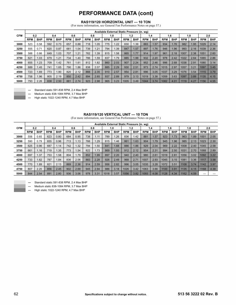
62 Specifications subject to change without notice. 513 56 3222 02 Rev. B
RAS119/120 HORIZONTAL UNIT — 10 TON(For more information, see General Fan Performance Notes on page 57.)
RAS119/120 VERTICAL UNIT — 10 TON(For more information, see General Fan Performance Notes on page 57.)
CFMAvailable External Static Pressure (in. wg)
0.2 0.4 0.6 0.8 1.0 1.2 1.4 1.6 1.8 2.0RPM BHP RPM BHP RPM BHP RPM BHP RPM BHP RPM BHP RPM BHP RPM BHP RPM BHP RPM BHP
3000 523 0.58 592 0.73 657 0.88 718 1.05 775 1.22 830 1.39 883 1.57 934 1.76 982 1.95 1029 2.14
3250 555 0.71 620 0.87 681 1.04 739 1.21 794 1.39 847 1.57 897 1.76 946 1.96 993 2.16 1039 2.36
3500 588 0.86 649 1.03 707 1.21 762 1.39 815 1.58 865 1.77 914 1.97 961 2.18 1007 2.38 1051 2.60
3750 621 1.03 679 1.21 734 1.40 786 1.59 837 1.79 885 1.99 932 2.20 978 2.42 1022 2.64 1065 2.86
4000 655 1.23 709 1.42 761 1.61 812 1.82 860 2.03 907 2.24 952 2.46 996 2.68 1038 2.91 1080 3.14
4250 689 1.45 741 1.65 790 1.86 838 2.07 885 2.29 930 2.51 973 2.74 1015 2.97 1057 3.21 1097 3.45
4500 723 1.69 773 1.90 820 2.12 866 2.35 910 2.57 954 2.81 996 3.05 1037 3.29 1076 3.54 1115 3.79
4750 758 1.96 805 2.19 850 2.42 894 2.65 937 2.89 979 3.13 1019 3.38 1059 3.63 1097 3.89 1135 4.15
5000 793 2.26 838 2.50 881 2.74 923 2.98 965 3.23 1005 3.49 1044 3.74 1082 4.01 1119 4.27 1156 4.55
— Standard static 591-838 RPM, 2.4 Max BHP— Medium static 838-1084 RPM, 3.7 Max BHP— High static 1022-1240 RPM, 4.7 Max BHP
CFMAvailable External Static Pressure (in. wg)
0.2 0.4 0.6 0.8 1.0 1.2 1.4 1.6 1.8 2.0RPM BHP RPM BHP RPM BHP RPM BHP RPM BHP RPM BHP RPM BHP RPM BHP RPM BHP RPM BHP
3000 556 0.65 623 0.80 684 0.95 738 1.11 789 1.26 836 1.42 881 1.57 923 1.73 963 1.89 1001 2.05
3250 590 0.79 655 0.96 713 1.13 766 1.29 815 1.46 861 1.63 904 1.79 945 1.96 985 2.13 1023 2.30
3500 625 0.96 687 1.14 742 1.32 794 1.50 841 1.68 886 1.86 929 2.04 969 2.22 1008 2.40 1045 2.58
3750 661 1.16 719 1.35 773 1.54 822 1.73 869 1.93 912 2.12 954 2.31 994 2.50 1031 2.70 1068 2.89
4000 697 1.37 753 1.58 804 1.79 852 1.99 897 2.20 940 2.40 980 2.61 1019 2.81 1056 3.02 1092 3.22
4250 733 1.62 787 1.84 836 2.06 883 2.28 926 2.49 968 2.71 1007 2.93 1045 3.15 1081 3.36 1117 3.58
4500 770 1.89 821 2.13 869 2.36 914 2.59 956 2.82 996 3.05 1035 3.28 1072 3.51 1108 3.74 1142 3.97
4750 807 2.20 856 2.45 902 2.69 945 2.94 986 3.18 1026 3.42 1063 3.66 1100 3.91 1135 4.15 1168 4.39
5000 844 2.54 891 2.80 936 3.06 978 3.31 1018 3.57 1056 3.82 1093 4.08 1128 4.34 1162 4.59 — —
— Standard static 591-838 RPM, 2.4 Max BHP— Medium static 838-1084 RPM, 3.7 Max BHP— High static 1022-1240 RPM, 4.7 Max BHP
PERFORMANCE DATA (cont)

513 56 3222 02 Rev. B Specifications subject to change without notice. 63
RAS150 HORIZONTAL UNIT — 12.5 TON(For more information, see General Fan Performance Notes on page 57.)
RAS150 VERTICAL UNIT — 12.5 TON(For more information, see General Fan Performance Notes on page 57.)
CFMAvailable External Static Pressure (in. wg)
0.2 0.4 0.6 0.8 1.0 1.2 1.4 1.6 1.8 2.0RPM BHP RPM BHP RPM BHP RPM BHP RPM BHP RPM BHP RPM BHP RPM BHP RPM BHP RPM BHP
3438 580 0.82 642 0.99 700 1.16 756 1.34 809 1.53 860 1.72 910 1.92 957 2.12 1003 2.32 1048 2.54
3750 621 1.03 679 1.21 734 1.40 786 1.59 837 1.79 885 1.99 932 2.20 978 2.42 1022 2.64 1065 2.86
4063 663 1.28 717 1.47 769 1.67 818 1.88 866 2.09 912 2.31 957 2.53 1001 2.75 1043 2.98 1084 3.22
4375 706 1.56 757 1.77 805 1.98 852 2.20 897 2.43 941 2.66 984 2.89 1026 3.13 1066 3.37 1106 3.62
4688 749 1.89 797 2.11 843 2.34 887 2.57 930 2.81 972 3.05 1013 3.29 1053 3.54 1092 3.80 1130 4.06
5000 793 2.26 838 2.50 881 2.74 923 2.98 965 3.23 1005 3.49 1044 3.74 1082 4.01 1119 4.27 1156 4.55
5313 837 2.69 880 2.93 921 3.19 961 3.44 1000 3.71 1038 3.97 1076 4.24 1113 4.52 — — — —
5625 882 3.16 922 3.42 961 3.68 999 3.95 1037 4.23 1073 4.51 — — — — — — — —
5938 926 3.68 964 3.96 1001 4.23 1038 4.52 — — — — — — — — — — — —
6250 971 4.26 1007 4.55 — — — — — — — — — — — — — — — —
— Standard static 652-843 RPM, 2.9 Max BHP— Medium static 838-1084 RPM, 3.7 Max BHP— High static 1022-1240 RPM, 4.7 Max BHP
BOLD — Indicated field-supplied drive.
CFMAvailable External Static Pressure (in. wg)
0.2 0.4 0.6 0.8 1.0 1.2 1.4 1.6 1.8 2.0RPM BHP RPM BHP RPM BHP RPM BHP RPM BHP RPM BHP RPM BHP RPM BHP RPM BHP RPM BHP
3438 616 0.92 679 1.10 735 1.27 786 1.45 835 1.62 880 1.80 922 1.98 963 2.15 1002 2.33 1039 2.51
3750 661 1.16 719 1.35 773 1.54 822 1.73 869 1.93 912 2.12 954 2.31 994 2.50 1031 2.70 1068 2.89
4063 706 1.43 761 1.64 812 1.85 860 2.06 904 2.27 947 2.48 987 2.68 1025 2.89 1062 3.10 1098 3.31
4375 752 1.75 804 1.98 852 2.20 898 2.43 941 2.65 982 2.88 1021 3.10 1058 3.32 1094 3.55 1129 3.77
4688 798 2.12 847 2.36 894 2.60 937 2.85 979 3.09 1018 3.33 1056 3.57 1093 3.81 1128 4.04 1162 4.29
5000 844 2.54 891 2.80 936 3.06 978 3.31 1018 3.57 1056 3.82 1093 4.08 1128 4.34 1162 4.59 — —
5313 891 3.01 936 3.28 978 3.56 1019 3.83 1057 4.11 1094 4.38 1130 4.65 — — — — — —
5625 938 3.53 981 3.83 1022 4.12 1060 4.41 1097 4.70 — — — — — — — — — —
5938 986 4.12 1026 4.43 — — — — — — — — — — — — — — — —
6250 — — — — — — — — — — — — — — — — — — — —
— Standard static 652-843 RPM, 2.9 Max BHP— Medium static 838-1084 RPM, 3.7 Max BHP— High static 1022-1240 RPM, 4.7 Max BHP
BOLD — Indicated field-supplied drive.
PERFORMANCE DATA (cont)

64 Specifications subject to change without notice. 513 56 3222 02 Rev. B
RAS180 HORIZONTAL UNIT — 15 TON(For more information, see General Fan Performance Notes on page 57.)
RAS180 VERTICAL UNIT — 15 TON(For more information, see General Fan Performance Notes on page 57.)
CFMAvailable External Static Pressure (in. wg)
0.2 0.4 0.6 0.8 1.0 1.2 1.4 1.6 1.8 2.0RPM BHP RPM BHP RPM BHP RPM BHP RPM BHP RPM BHP RPM BHP RPM BHP RPM BHP RPM BHP
4500 423 0.77 487 0.99 545 1.22 601 1.47 655 1.73 707 2.02 758 2.33 806 2.66 853 3.01 898 3.374875 447 0.94 507 1.18 563 1.42 615 1.67 666 1.95 716 2.24 764 2.55 811 2.89 856 3.24 900 3.615250 471 1.13 528 1.38 581 1.64 631 1.91 679 2.19 726 2.49 772 2.81 817 3.14 860 3.50 903 3.87
5625 496 1.35 550 1.62 600 1.89 648 2.17 694 2.46 738 2.77 782 3.09 825 3.43 867 3.79 908 4.17
6000 520 1.59 572 1.88 620 2.17 666 2.46 710 2.76 752 3.08 794 3.41 835 3.76 875 4.12 914 4.50
6375 545 1.86 594 2.17 640 2.47 684 2.78 726 3.10 767 3.42 807 3.76 846 4.12 885 4.49 923 4.87
6750 571 2.17 617 2.48 661 2.81 704 3.13 744 3.46 784 3.80 822 4.15 859 4.51 896 4.89 933 5.28
7125 596 2.50 640 2.83 683 3.17 724 3.52 763 3.86 801 4.22 838 4.58 874 4.95 909 5.33 944 5.73
7500 622 2.87 663 3.22 705 3.58 744 3.93 782 4.30 818 4.66 854 5.04 889 5.42 923 5.81 — —
— Standard static 507-676 RPM, 2.9 Max BHP— Medium static 627-851 RPM, 3.7 Max BHP— High static 776-955 RPM, 6.1 Max BHP
BOLD — Indicated field-supplied drive.
CFMAvailable External Static Pressure (in. wg)
0.2 0.4 0.6 0.8 1.0 1.2 1.4 1.6 1.8 2.0RPM BHP RPM BHP RPM BHP RPM BHP RPM BHP RPM BHP RPM BHP RPM BHP RPM BHP RPM BHP
4500 425 0.76 490 1.02 550 1.30 607 1.61 664 1.96 719 2.34 772 2.76 823 3.20 872 3.67 918 4.16
4875 448 0.92 510 1.20 566 1.49 621 1.81 674 2.15 725 2.54 776 2.95 825 3.40 873 3.87 919 4.37
5250 472 1.10 531 1.40 584 1.70 636 2.03 686 2.38 734 2.76 783 3.18 830 3.63 876 4.10 920 4.60
5625 496 1.30 552 1.62 603 1.94 652 2.28 699 2.64 746 3.03 791 3.44 836 3.89 880 4.36 923 4.86
6000 520 1.52 574 1.86 623 2.20 670 2.55 715 2.92 759 3.32 802 3.74 845 4.18 887 4.66 928 5.16
6375 544 1.77 596 2.13 644 2.49 688 2.86 731 3.24 773 3.64 814 4.07 855 4.52 895 4.99 935 5.49
6750 568 2.05 618 2.43 664 2.81 707 3.19 749 3.59 789 4.00 828 4.43 867 4.89 905 5.36 943 5.87
7125 593 2.35 641 2.75 685 3.16 727 3.56 767 3.97 806 4.39 844 4.84 881 5.29 917 5.78 — —
7500 617 2.69 664 3.11 707 3.53 747 3.95 786 4.38 823 4.82 860 5.27 895 5.74 — — — —
— Standard static 507-676 RPM, 2.9 Max BHP— Medium static 627-851 RPM, 3.7 Max BHP— High static 776-955 RPM, 6.1 Max BHP
BOLD — Indicated field-supplied drive.
PERFORMANCE DATA (cont)

513 56 3222 02 Rev. B Specifications subject to change without notice. 65
LEGEND AND NOTES Applicable for Electrical Data Tables on pages 66-123
LEGEND
NOTES1. In compliance with NEC requirements for multi-motor and combination load
equipment (refer to NEC Articles 430 and 440), the overcurrent protectivedevice for the unit shall be fuse or HACR breaker. Canadian units may befuse or circuit breaker.
2. Unbalanced 3-Phase Supply VoltageNever operate a motor where a phase imbalance in supply voltage is greaterthan 2%. Use the following formula to determine the percentage of voltageimbalance.
Example: Supply voltage is 230-3-60
AB = 224 v
BC = 231 v
AC = 226 v
Determine maximum deviation from average voltage.(AB) 227 – 224 = 3 v(BC) 231 – 227 = 4 v(AC) 227 – 226 = 1 vMaximum deviation is 4 v.Determine percent of voltage imbalance.
= 1.76%
This amount of phase imbalance is satisfactory as it is below the maximum allowable 2%.
IMPORTANT: If the supply voltage phase imbalance is more than 2%,contact your local electric utility company immediately.
BRKR — Circuit breakerC.O. — Convenience outletDISC — DisconnectEFF — EfficiencyFLA — Full load ampsLRA — Locked rotor ampsMCA — Minimum circuit ampsMOCP — MAX FUSE or HACR BreakerP.E. — Power exhaustPwrd fr/unit — Powered from unitPWRD C.O. — Powered convenience outletRLA — Rated load ampsUNPWR C.O. — Unpowered convenience outlet
% Voltage Imbalance = 100 xmax voltage deviation from average voltage
average voltage
Average Voltage =(224 + 231 + 226)
=681
3 3
= 227
% Voltage Imbalance = 100 x4
227
ELECTRICAL DATA

66 Specifications subject to change without notice. 513 56 3222 02 Rev. B
See Legend and Notes on page 65.
SINGLE SPEED INDOOR FAN MOTOR, 6 to 15 TONS
UNITSIZE V-Ph-Hz
VOLTAGE RANGE COMP 1 COMP 2 OFM (ea) IFM
RLA LRA RLA LRA Watts FLA TYPE EFF at Full Load FLAMin Max
RAS072(1-Circuit/1-StageCooling)
208-3-60 187 253 19.6 136 — —325 1.5 STD 69% 5.2325 1.5 MED 89% 8.4325 1.5 HIGH 87% 10.6
230-3-60 187 253 19.6 136 — —325 1.5 STD 69% 5.2325 1.5 MED 89% 8.3325 1.5 HIGH 87% 10.6
460-3-60 414 506 8.2 66 — —325 0.8 STD 69% 2.6325 0.8 MED 89% 4.2325 0.8 HIGH 87% 5.3
575-3-60 518 633 6.6 55 — —325 0.6 STD 78% 2.0325 0.6 MED 77% 2.8325 0.6 HIGH 77% 2.8
RAS090(2-Circuit/2-StageCooling)
208-3-60 187 253 13.6 83 13.6 83325 1.5 STD 87% 5.2325 1.5 MED 89% 8.4325 1.5 HIGH 83% 13.6
230-3-60 187 253 13.6 83 13.6 83325 1.5 STD 87% 4.9325 1.5 MED 89% 8.3325 1.5 HIGH 83% 12.7
460-3-60 414 506 6.1 41 6.1 41325 0.8 STD 87% 2.5325 0.8 MED 89% 4.2325 0.8 HIGH 83% 6.4
575-3-60 518 633 4.2 33 4.2 33325 0.6 STD 87% 2.8325 0.6 MED 77% 2.8325 0.6 HIGH 81% 5.6
RAS089(1-Circuit /
2-StageCooling)
208-3-60 187 253 28.8 164 — —325 1.5 STD 87% 5.2325 1.5 MED 89% 8.4
230-3-60 187 253 26.8 164 — —325 1.5 STD 87% 4.9325 1.5 MED 89% 8.3
460-3-60 414 506 12.0 94 — —325 0.8 STD 87% 2.5325 0.8 MED 89% 4.2
575-3-60 518 633 9.0 65 — —325 0.6 STD 87% 2.8325 0.6 MED 77% 2.8
RAS102(2-Circuit/2-StageCooling)
208-3-60 187 253 14.5 98 13.7 83325 1.5 STD 75% 5.2325 1.5 MED 87% 6.9325 1.5 HIGH 87% 10.6
230-3-60 187 253 14.5 98 13.7 83325 1.5 STD 75% 5.2325 1.5 MED 87% 6.7325 1.5 HIGH 87% 10.6
460-3-60 414 506 6.3 55 6.2 41325 0.8 STD 75% 2.6325 0.8 MED 87% 3.4325 0.8 HIGH 87% 5.3
575-3-60 518 633 6.0 41 4.8 33325 0.6 STD 72% 1.6325 0.6 MED 78% 2.0325 0.6 HIGH 77% 2.8
RAS100(1-Circuit /
2-StageCooling)
208-3-60 187 253 28.8 223 — —325 1.5 STD 75% 5.2325 1.5 MED 87% 6.9325 1.5 HIGH 87% 10.6
230-3-60 187 253 28.8 223 — —325 1.5 STD 75% 5.2325 1.5 MED 87% 6.7325 1.5 HIGH 87% 10.6
460-3-60 414 506 12.5 100 — —325 0.8 STD 75% 2.6325 0.8 MED 87% 3.4325 0.8 HIGH 87% 5.3
575-3-60 518 633 9.7 70 — —325 0.6 STD 72% 1.6325 0.6 MED 78% 2.0325 0.6 HIGH 77% 2.8
ELECTRICAL DATA (cont)

513 56 3222 02 Rev. B Specifications subject to change without notice. 67
See Legend and Notes on page 65.
SINGLE SPEED INDOOR FAN MOTOR, 6-15 TONS (cont)
UNITSIZE V-Ph-Hz
VOLTAGE RANGE COMP 1 COMP 2 OFM (ea) IFM
RLA LRA RLA LRA Watts FLA TYPE EFF at Full Load FLAMin Max
RAS120(2-Circuit/2-StageCooling)
208-3-60 187 253 15.6 110 15.9 110325 1.5 STD 69% 5.2325 1.5 MED 87% 10.6325 1.5 HIGH 83% 13.6
230-3-60 187 253 15.6 110 15.9 110325 1.5 STD 69% 5.2325 1.5 MED 87% 10.6325 1.5 HIGH 83% 12.7
460-3-60 414 506 7.7 52 7.7 52325 0.8 STD 69% 2.6325 0.8 MED 87% 5.3325 0.8 HIGH 83% 6.4
575-3-60 518 633 5.8 39 5.7 39325 0.6 STD 78% 2.0325 0.6 MED 77% 2.8325 0.6 HIGH 81% 5.6
RAS119(1-Circuit /
2-StageCooling)
208-3-60 187 253 32.5 240 — —325 1.5 STD 69% 5.2325 1.5 MED 87% 10.6325 1.5 HIGH 83% 13.6
230-3-60 187 253 32.5 240 — —325 1.5 STD 69% 5.2325 1.5 MED 87% 10.6325 1.5 HIGH 83% 12.7
460-3-60 414 506 14.8 130 — —325 0.8 STD 69% 2.6325 0.8 MED 87% 5.3325 0.8 HIGH 83% 6.4
575-3-60 518 633 11.1 94 — —325 0.6 STD 78% 2.0325 0.6 MED 77% 2.8325 0.6 HIGH 81% 5.6
RAS150(2-Circuit/2-StageCooling)
208-3-60 187 253 19.6 136 22.4 1491070 6.2 STD 89% 8.41070 6.2 MED 87% 10.61070 6.2 HIGH 83% 13.6
230-3-60 187 253 19.6 136 22.4 1491070 6.2 STD 89% 8.31070 6.2 MED 87% 10.61070 6.2 HIGH 83% 12.7
460-3-60 414 506 8.2 66 10.6 751070 3.1 STD 89% 4.21070 3.1 MED 87% 5.31070 3.1 HIGH 83% 6.4
575-3-60 518 633 6.6 55 7.7 541070 2.5 STD 77% 2.81070 2.5 MED 77% 2.81070 2.5 HIGH 81% 5.6
RAS180(2-Circuit/2-StageCooling)
208-3-60 187 253 25.0 164 25.0 164
280 1.5 STD 89% 8.4280 1.5 MED 87% 10.6280 1.5 HIGH 87% 17.0280 1.5 HIGH EFF 90% 20.4
230-3-60 187 253 25.0 164 25.0 164
280 1.5 STD 89% 8.3280 1.5 MED 87% 10.6280 1.5 HIGH 87% 15.0280 1.5 HIGH EFF 90% 20.4
460-3-60 414 506 12.2 100 12.8 100
280 0.8 STD 89% 4.2280 0.8 MED 87% 5.3280 0.8 HIGH 87% 7.6280 0.8 HIGH EFF 90% 10.2
575-3-60 518 633 9.8 78 9.6 78
280 0.6 STD 77% 2.8280 0.6 MED 77% 2.8280 0.6 HIGH 90% 6.1280 0.6 HIGH EFF 94% 9.0
ELECTRICAL DATA (cont)

68 Specifications subject to change without notice. 513 56 3222 02 Rev. B
See Legend and Notes on page 65.
1-STAGE COOLING WITH TWO-SPEED INDOOR FAN MOTOR, 6 TONS
UNITSIZE V-Ph-Hz
VOLTAGE RANGE COMP 1 COMP 2 OFM (ea) IFM
RLA LRA RLA LRA Watts FLA TYPE EFF at Full Load FLAMin Max
RAS072(1-Circuit/1-StageCooling)
208-3-60 187 253 19.6 136 — —
325 1.5 STD 0.77 7.1
325 1.5 MED 0.85 8.6
325 1.5 HIGH 0.82 10.8
230-3-60 187 253 19.6 136 — —
325 1.5 STD 0.77 6.8
325 1.5 MED 0.85 7.8
325 1.5 HIGH 0.82 9.8
460-3-60 414 506 8.2 66 — —
325 0.8 STD 0.77 3.4
325 0.8 MED 0.85 3.8
325 0.8 HIGH 0.82 4.9
575-3-60 518 633 6.6 55 — —
325 0.6 STD 0.80 3.5
325 0.6 MED 0.84 4.5
325 0.6 HIGH 0.84 4.5
TWO-SPEED INDOOR FAN MOTOR, 7.5-15 TONS
UNITSIZE V-Ph-Hz
VOLTAGE RANGE COMP 1 COMP 2 OFM (ea) IFM
RLA LRA RLA LRA Watts FLA TYPE EFF at Full Load FLAMin Max
RAS090(2-Circuit/2-Stage Cooling)
208-3-60 187 253 13.6 83 13.6 83
325 1.5 STD 0.84 5.8
325 1.5 MED 0.85 8.6
325 1.5 HIGH 0.84 13.6
230-3-60 187 253 13.6 83 13.6 83
325 1.5 STD 0.84 5.6
325 1.5 MED 0.85 7.8
325 1.5 HIGH 0.84 12.7
460-3-60 414 506 6.1 41 6.1 41
325 0.8 STD 0.79 2.9
325 0.8 MED 0.85 3.8
325 0.8 HIGH 0.84 6.4
575-3-60 518 633 4.2 33 4.2 33
325 0.6 STD 0.81 2.8
325 0.6 MED 0.84 4.5
325 0.6 HIGH 0.83 6.2
RAS102(2-Circuit/2-Stage Cooling)
208-3-60 187 253 14.5 98 13.7 83
325 1.5 STD 0.84 5.8
325 1.5 MED 0.77 7.1
325 1.5 HIGH 0.82 10.8
230-3-60 187 253 14.5 98 13.7 83
325 1.5 STD 0.84 5.6
325 1.5 MED 0.77 6.8
325 1.5 HIGH 0.82 9.8
460-3-60 414 506 6.3 55 6.2 41
325 0.8 STD 0.79 2.9
325 0.8 MED 0.77 3.4
325 0.8 HIGH 0.82 4.9
575-3-60 518 633 6.0 41 4.8 33
325 0.6 STD 0.81 2.8
325 0.6 MED 0.80 3.5
325 0.6 HIGH 0.84 4.5
ELECTRICAL DATA (cont)
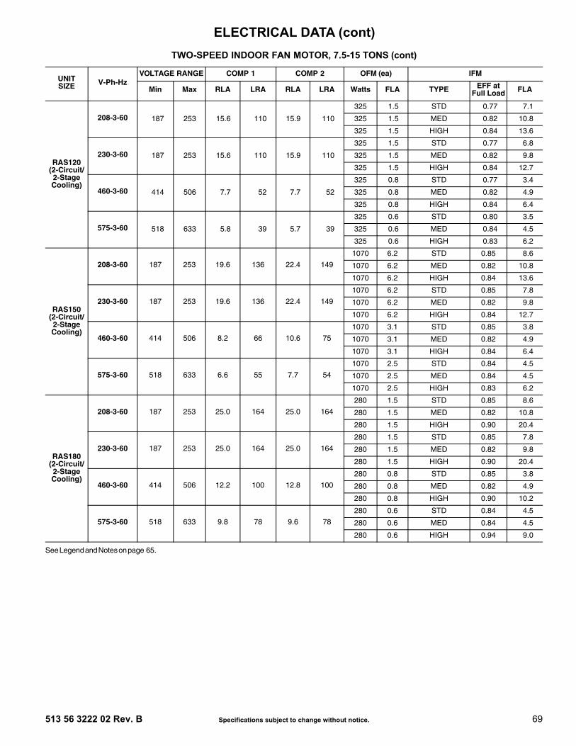
513 56 3222 02 Rev. B Specifications subject to change without notice. 69
See Legend and Notes on page 65.
RAS120(2-Circuit/2-Stage Cooling)
208-3-60 187 253 15.6 110 15.9 110
325 1.5 STD 0.77 7.1
325 1.5 MED 0.82 10.8
325 1.5 HIGH 0.84 13.6
230-3-60 187 253 15.6 110 15.9 110
325 1.5 STD 0.77 6.8
325 1.5 MED 0.82 9.8
325 1.5 HIGH 0.84 12.7
460-3-60 414 506 7.7 52 7.7 52
325 0.8 STD 0.77 3.4
325 0.8 MED 0.82 4.9
325 0.8 HIGH 0.84 6.4
575-3-60 518 633 5.8 39 5.7 39
325 0.6 STD 0.80 3.5
325 0.6 MED 0.84 4.5
325 0.6 HIGH 0.83 6.2
RAS150(2-Circuit/2-Stage Cooling)
208-3-60 187 253 19.6 136 22.4 149
1070 6.2 STD 0.85 8.6
1070 6.2 MED 0.82 10.8
1070 6.2 HIGH 0.84 13.6
230-3-60 187 253 19.6 136 22.4 149
1070 6.2 STD 0.85 7.8
1070 6.2 MED 0.82 9.8
1070 6.2 HIGH 0.84 12.7
460-3-60 414 506 8.2 66 10.6 75
1070 3.1 STD 0.85 3.8
1070 3.1 MED 0.82 4.9
1070 3.1 HIGH 0.84 6.4
575-3-60 518 633 6.6 55 7.7 54
1070 2.5 STD 0.84 4.5
1070 2.5 MED 0.84 4.5
1070 2.5 HIGH 0.83 6.2
RAS180(2-Circuit/2-Stage Cooling)
208-3-60 187 253 25.0 164 25.0 164
280 1.5 STD 0.85 8.6
280 1.5 MED 0.82 10.8
280 1.5 HIGH 0.90 20.4
230-3-60 187 253 25.0 164 25.0 164
280 1.5 STD 0.85 7.8
280 1.5 MED 0.82 9.8
280 1.5 HIGH 0.90 20.4
460-3-60 414 506 12.2 100 12.8 100
280 0.8 STD 0.85 3.8
280 0.8 MED 0.82 4.9
280 0.8 HIGH 0.90 10.2
575-3-60 518 633 9.8 78 9.6 78
280 0.6 STD 0.84 4.5
280 0.6 MED 0.84 4.5
280 0.6 HIGH 0.94 9.0
TWO-SPEED INDOOR FAN MOTOR, 7.5-15 TONS (cont)
UNITSIZE V-Ph-Hz
VOLTAGE RANGE COMP 1 COMP 2 OFM (ea) IFM
RLA LRA RLA LRA Watts FLA TYPE EFF at Full Load FLAMin Max
ELECTRICAL DATA (cont)

70 Specifications subject to change without notice. 513 56 3222 02 Rev. B
LEGEND
SINGLE SPEED INDOOR FAN MOTORWITHOUT FACTORY INSTALLED NON-FUSED DISCONNECT
UNITSIZE
NOM.V-Ph-Hz
IFMTYPE
ELECTRIC HEATERPART NUMBER
CRHEATERXXXXXX
NOMPWR(kW)
APPPWR(kW)
SINGLE POINT KIT PART NUMBERCRSINGLEXXXA00
NO C.O. or Unpowered C.O. w/PWRD C.O.
NO P.E. w/ P.E. (pwrd fr/unit) NO P.E. w/ P.E.
(pwrd fr/unit)
RA
S07
2 (1
-Cir
cuit
/ 1-
Sta
ge
Co
olin
g)
208/
230-
3-60
STD
102A00 6.5 4.9/6.0 — — — —104B00 10.5 7.9/9.6 — — — —105A00 16.0 12.0/14.7 037 037 038 038
104B00,104B00 21.0 15.8/19.3 038 038 038 038104B00,105A00 26.5 19.9/24.3 038 038 038 038
MED
102A00 6.5 4.9/6.0 — — — —104B00 10.5 7.9/9.6 — — — —105A00 16.0 12.0/14.7 037 038 038 038
104B00,104B00 21.0 15.8/19.3 038 038 038 038104B00,105A00 26.5 19.9/24.3 038 038 038 038
HIGH
102A00 6.5 4.9/6.0 — — — —104B00 10.5 7.9/9.6 — — — 037105A00 16.0 12.0/14.7 038 038 038 038
104B00,104B00 21.0 15.8/19.3 038 038 038 038104B00,105A00 26.5 19.9/24.3 038 038 038 038
460-
3-60
STD
106A00 6.0 5.5 — — — —108A00 11.5 10.6 — — — —109A00 14.0 12.9 — — — —
108A00,108A00 23.0 21.1 037 037 037 037108A00,109A00 25.5 23.4 037 037 037 037
MED
106A00 6.0 5.5 — — — —108A00 11.5 10.6 — — — —109A00 14.0 12.9 — — — —
108A00,108A00 23.0 21.1 037 037 037 037108A00,109A00 25.5 23.4 037 037 037 037
HIGH
106A00 6.0 5.5 — — — —108A00 11.5 10.6 — — — —109A00 14.0 12.9 — — — —
108A00,108A00 23.0 21.1 037 037 037 037108A00,109A00 25.5 23.4 037 037 037 037
APP PWR — 208 / 230V / 460V / 575VC.O. — Convenience outletFLA — Full load ampsIFM — Indoor fan motorNOM PWR — 240V / 480V / 600VP.E. — Power exhaustPWRD — Powered convenience outletUNPWRD — Unpowered convenience outlet
ELECTRICAL DATA (cont)

513 56 3222 02 Rev. B Specifications subject to change without notice. 71
LEGEND
SINGLE SPEED INDOOR FAN MOTORWITH FACTORY INSTALLED NON-FUSED DISCONNECT
UNITSIZE
NOM.V-Ph-Hz
IFMTYPE
ELECTRIC HEATERPART NUMBER
CRHEATERXXXXXX
NOMPWR(kW)
APPPWR(kW)
SINGLE POINT KIT PART NUMBERCRSINGLEXXXA00
NO C.O. or Unpowered C.O. w/PWRD C.O.
NO P.E. w/ P.E. (pwrd fr/unit) NO P.E. w/ P.E.
(pwrd fr/unit)
RA
S07
2 (1
-Cir
cuit
/ 1-
Sta
ge
Co
olin
g) 20
8/23
0-3-
60
STD
102A00 6.5 4.9/6.0 037 037 037 037104B00 10.5 7.9/9.6 037 037 037 037105A00 16.0 12.0/14.7 037 037 038 038
104B00,104B00 21.0 15.8/19.3 038 038 038 038104B00,105A00 26.5 19.9/24.3 038 038 038 038
MED
102A00 6.5 4.9/6.0 037 037 037 037104B00 10.5 7.9/9.6 037 037 037 037105A00 16.0 12.0/14.7 037 038 038 038
104B00,104B00 21.0 15.8/19.3 038 038 038 038104B00,105A00 26.5 19.9/24.3 038 038 038 038
HIGH
102A00 6.5 4.9/6.0 037 037 037 037104B00 10.5 7.9/9.6 037 037 037 037105A00 16.0 12.0/14.7 038 038 038 038
104B00,104B00 21.0 15.8/19.3 038 038 038 038104B00,105A00 26.5 19.9/24.3 038 038 038 038
460-
3-60
STD
106A00 6.0 5.5 — — — —108A00 11.5 10.6 — — — —109A00 14.0 12.9 — — — —
108A00,108A00 23.0 21.1 037 037 037 037108A00,109A00 25.5 23.4 037 037 037 037
MED
106A00 6.0 5.5 — — — —108A00 11.5 10.6 — — — —109A00 14.0 12.9 — — — —
108A00,108A00 23.0 21.1 037 037 037 037108A00,109A00 25.5 23.4 037 037 037 037
HIGH
106A00 6.0 5.5 — — — —108A00 11.5 10.6 — — — —109A00 14.0 12.9 — — — —
108A00,108A00 23.0 21.1 037 037 037 037108A00,109A00 25.5 23.4 037 037 037 037
APP PWR — 208 / 230V / 460V / 575VC.O. — Convenience outletFLA — Full load ampsIFM — Indoor fan motorNOM PWR — 240V / 480V / 600VP.E. — Power exhaustPWRD — Powered convenience outletUNPWRD — Unpowered convenience outlet
ELECTRICAL DATA (cont)

72 Specifications subject to change without notice. 513 56 3222 02 Rev. B
LEGEND
TWO SPEED INDOOR FAN MOTORWITH OR WITHOUT FACTORY INSTALLED NON-FUSED DISCONNECT
UNITSIZE
NOM.V-Ph-Hz
IFMTYPE
ELECTRIC HEATERPART NUMBER
CRHEATERXXXXXX
NOMPWR(kW)
APPPWR(kW)
SINGLE POINT KIT PART NUMBERCRSINGLEXXXA00
NO C.O. or Unpowered C.O. w/PWRD C.O.
NO P.E. w/ P.E. (pwrd fr/unit) NO P.E. w/ P.E.
(pwrd fr/unit)
RA
S07
2 (1
-Cir
cuit
/ 1-
Sta
ge
Co
olin
g)
208/
230-
3-60
STD
102A00 6.5 4.9/6.0 — — — —104B00 10.5 7.9/9.6 — — — —105A00 16.0 12.0/14.7 037 037 038 038
104B00,104B00 21.0 15.8/19.3 038 038 038 038104B00,105A00 26.5 19.9/24.3 038 038 038 038
MED
102A00 6.5 4.9/6.0 — — — —104B00 10.5 7.9/9.6 — — — —105A00 16.0 12.0/14.7 037 038 038 038
104B00,104B00 21.0 15.8/19.3 038 038 038 038104B00,105A00 26.5 19.9/24.3 038 038 038 038
HIGH
102A00 6.5 4.9/6.0 — — — —104B00 10.5 7.9/9.6 — — — 037105A00 16.0 12.0/14.7 038 038 038 038
104B00,104B00 21.0 15.8/19.3 038 038 038 038104B00,105A00 26.5 19.9/24.3 038 038 038 038
460-
3-60
STD
106A00 6.0 5.5 — — — —108A00 11.5 10.6 — — — —109A00 14.0 12.9 — — — —
108A00,108A00 23.0 21.1 037 037 037 037108A00,109A00 25.5 23.4 037 037 037 037
MED
106A00 6.0 5.5 — — — —108A00 11.5 10.6 — — — —109A00 14.0 12.9 — — — —
108A00,108A00 23.0 21.1 037 037 037 037108A00,109A00 25.5 23.4 037 037 037 037
HIGH
106A00 6.0 5.5 — — — —108A00 11.5 10.6 — — — —109A00 14.0 12.9 — — — —
108A00,108A00 23.0 21.1 037 037 037 037108A00,109A00 25.5 23.4 037 037 037 037
APP PWR — 208 / 230V / 460V / 575VC.O. — Convenience outletFLA — Full load ampsIFM — Indoor fan motorNOM PWR — 240V / 480V / 600VP.E. — Power exhaustPWRD — Powered convenience outletUNPWRD — Unpowered convenience outlet
ELECTRICAL DATA (cont)

513 56 3222 02 Rev. B Specifications subject to change without notice. 73
LEGEND
SINGLE SPEED INDOOR FAN MOTOR WITHOUT FACTORY INSTALLED NON-FUSED DISCONNECT
UNITSIZE
NOM.V-Ph-Hz
IFMTYPE
ELECTRIC HEATERPART NUMBER
CRHEATERXXXXXX
NOMPWR(kW)
APPPWR(kW)
SINGLE POINT KIT PART NUMBERCRSINGLEXXXA00
NO C.O. or Unpowered C.O. w/PWRD C.O.
NO P.E. w/ P.E. (pwrd fr/unit) NO P.E. w/ P.E.
(pwrd fr/unit)
RA
S09
0 (2
-Cir
cuit
/ 2-
Sta
ge
Co
olin
g)
208/
230-
3-60
STD
117A00 10.4 7.8/9.6 042 042 042 042110A00 16.0 12.0/14.7 042 042 043 043111A00 24.8 18.6/22.8 043 043 043 043112A00 32.0 24.0/29.4 043 043 043 043
112A00,117A00 42.4 31.8/38.9 045 045 045 045
MED
117A00 10.4 7.8/9.6 042 042 042 042110A00 16.0 12.0/14.7 042 043 043 043111A00 24.8 18.6/22.8 043 043 043 043112A00 32.0 24.0/29.4 043 043 043 043
112A00,117A00 42.4 31.8/38.9 045 045 045 045
HIGH
117A00 10.4 7.8/9.6 042 042 042 043110A00 16.0 12.0/14.7 043 043 043 043111A00 24.8 18.6/22.8 043 043 043 043112A00 32.0 24.0/29.4 043 043 043 043
112A00,117A00 42.4 31.8/38.9 045 045 045 045
460-
3-60
STD
116B00 13.9 12.8 042 042 042 042113B00 16.5 15.2 042 042 042 042114B00 27.8 25.5 042 042 042 042115B00 33.0 30.3 042 042 042 042128B00 41.7 38.3 044 044 044 044
MED
116B00 13.9 12.8 042 042 042 042113B00 16.5 15.2 042 042 042 042114B00 27.8 25.5 042 042 042 042115B00 33.0 30.3 042 042 042 042128B00 41.7 38.3 044 044 044 044
HIGH
116B00 13.9 12.8 042 042 042 042113B00 16.5 15.2 042 042 042 042114B00 27.8 25.5 042 042 042 042115B00 33.0 30.3 042 042 044 044128B00 41.7 38.3 044 044 044 044
575-
3-60
STD118A00 18.0 16.5 042 042 042 042119A00 36.0 33.1 042 042 042 042
MED118A00 18.0 16.5 042 042 042 042119A00 36.0 33.1 042 042 042 042
HIGH118A00 18.0 16.5 042 042 042 042119A00 36.0 33.1 042 042 042 042
APP PWR — 208 / 230V / 460V / 575VC.O. — Convenience outletFLA — Full load ampsIFM — Indoor fan motorNOM PWR — 240V / 480V / 600VP.E. — Power exhaustPWRD — Powered convenience outletUNPWRD — Unpowered convenience outlet
ELECTRICAL DATA (cont)

74 Specifications subject to change without notice. 513 56 3222 02 Rev. B
LEGEND
SINGLE SPEED INDOOR FAN MOTOR WITHOUT FACTORY INSTALLED NON-FUSED DISCONNECT
UNITSIZE
NOM.V-Ph-Hz
IFMTYPE
ELECTRIC HEATERPART NUMBER
CRHEATERXXXXXX
NOMPWR(kW)
APPPWR(kW)
SINGLE POINT KIT PART NUMBERCRSINGLEXXXA00
NO C.O. or Unpowered C.O. w/PWRD C.O.
NO P.E. w/ P.E. (pwrd fr/unit) NO P.E. w/ P.E.
(pwrd fr/unit)
RA
S08
9 (1
-Cir
cuit
/ 2-
Sta
ge
Co
olin
g)
208/
230-
3-60
STD
117A00 10.4 7.8/9.6 042 042 042 042110A00 16.0 12.0/14.7 042 042 043 043111A00 24.8 18.6/22.8 043 043 043 043112A00 32.0 24.0/29.4 043 043 043 043
112A00,117A00 42.4 31.8/38.9 045 045 045 045
MED
117A00 10.4 7.8/9.6 042 042 042 043110A00 16.0 12.0/14.7 042 043 043 043111A00 24.8 18.6/22.8 043 043 043 043112A00 32.0 24.0/29.4 043 043 043 043
112A00,117A00 42.4 31.8/38.9 045 045 045 045
460-
3-60
STD
116B00 13.9 12.8 042 042 042 042113B00 16.5 15.2 042 042 042 042114B00 27.8 25.5 042 042 042 042115B00 33.0 30.3 042 042 042 042128B00 41.7 38.3 044 044 044 044
MED
116B00 13.9 12.8 042 042 042 042113B00 16.5 15.2 042 042 042 042114B00 27.8 25.5 042 042 042 042115B00 33.0 30.3 042 042 042 042128B00 41.7 38.3 044 044 044 044
575-
3-60 STD
118A00 18.0 16.5 042 042 042 042119A00 36.0 33.1 042 042 042 042
MED118A00 18.0 16.5 042 042 042 042119A00 36.0 33.1 042 042 042 042
APP PWR — 208 / 230V / 460V / 575VC.O. — Convenience outletFLA — Full load ampsIFM — Indoor fan motorNOM PWR — 240V / 480V / 600VP.E. — Power exhaustPWRD — Powered convenience outletUNPWRD — Unpowered convenience outlet
ELECTRICAL DATA (cont)

513 56 3222 02 Rev. B Specifications subject to change without notice. 75
LEGEND
SINGLE SPEED INDOOR FAN MOTORWITH FACTORY INSTALLED NON-FUSED DISCONNECT
UNITSIZE
NOM.V-Ph-Hz
IFMTYPE
ELECTRIC HEATERPART NUMBER
CRHEATERXXXXXX
NOMPWR(kW)
APPPWR(kW)
SINGLE POINT KIT PART NUMBERCRSINGLEXXXA00
NO C.O. or Unpowered C.O. w/PWRD C.O.
NO P.E. w/ P.E. (pwrd fr/unit) NO P.E. w/ P.E.
(pwrd fr/unit)
RA
S09
0 (2
-Cir
cuit
/ 2-
Sta
ge
Co
olin
g)
208/
230-
3-60
STD
117A00 10.4 7.8/9.6 042 042 042 042110A00 16.0 12.0/14.7 042 042 043 043111A00 24.8 18.6/22.8 043 043 043 043112A00 32.0 24.0/29.4 043 043 043 043
112A00,117A00 42.4 31.8/38.9 045 045 045 045
MED
117A00 10.4 7.8/9.6 042 042 042 042110A00 16.0 12.0/14.7 042 043 043 043111A00 24.8 18.6/22.8 043 043 043 043112A00 32.0 24.0/29.4 043 043 043 043
112A00,117A00 42.4 31.8/38.9 045 045 045 045
HIGH
117A00 10.4 7.8/9.6 042 042 042 043110A00 16.0 12.0/14.7 043 043 043 043111A00 24.8 18.6/22.8 043 043 043 043112A00 32.0 24.0/29.4 043 043 043 043
112A00,117A00 42.4 31.8/38.9 045 045 045 045
460-
3-60
STD
116B00 13.9 12.8 042 042 042 042113B00 16.5 15.2 042 042 042 042114B00 27.8 25.5 042 042 042 042115B00 33.0 30.3 042 042 042 042128B00 41.7 38.3 044 044 044 044
MED
116B00 13.9 12.8 042 042 042 042113B00 16.5 15.2 042 042 042 042114B00 27.8 25.5 042 042 042 042115B00 33.0 30.3 042 042 042 042128B00 41.7 38.3 044 044 044 044
HIGH
116B00 13.9 12.8 042 042 042 042113B00 16.5 15.2 042 042 042 042114B00 27.8 25.5 042 042 042 042115B00 33.0 30.3 042 042 044 044128B00 41.7 38.3 044 044 044 044
575-
3-60
STD118A00 18.0 16.5 042 042 042 042119A00 36.0 33.1 042 042 042 042
MED118A00 18.0 16.5 042 042 042 042119A00 36.0 33.1 042 042 042 042
HIGH118A00 18.0 16.5 042 042 042 042119A00 36.0 33.1 042 042 042 042
APP PWR — 208 / 230V / 460V / 575VC.O. — Convenience outletFLA — Full load ampsIFM — Indoor fan motorNOM PWR — 240V / 480V / 600VP.E. — Power exhaustPWRD — Powered convenience outletUNPWRD — Unpowered convenience outlet
ELECTRICAL DATA (cont)

76 Specifications subject to change without notice. 513 56 3222 02 Rev. B
LEGEND
SINGLE SPEED INDOOR FAN MOTORWITH FACTORY INSTALLED NON-FUSED DISCONNECT
UNITSIZE
NOM.V-Ph-Hz
IFMTYPE
ELECTRIC HEATERPART NUMBER
CRHEATERXXXXXX
NOMPWR(kW)
APPPWR(kW)
SINGLE POINT KIT PART NUMBERCRSINGLEXXXA00
NO C.O. or Unpowered C.O. w/PWRD C.O.
NO P.E. w/ P.E. (pwrd fr/unit) NO P.E. w/ P.E.
(pwrd fr/unit)
RA
S08
9 (1
-Cir
cuit
/ 2-
Sta
ge
Co
olin
g)
208/
230-
3-60
STD
117A00 10.4 7.8/9.6 047 047 047 049110A00 16.0 12.0/14.7 047 047 049 049111A00 24.8 18.6/22.8 049 049 049 049112A00 32.0 24.0/29.4 049 049 049 049
112A00,117A00 42.4 31.8/38.9 051 051 051 051
MED
117A00 10.4 7.8/9.6 047 047 047 049110A00 16.0 12.0/14.7 047 049 049 049111A00 24.8 18.6/22.8 049 049 049 049112A00 32.0 24.0/29.4 049 049 049 049
112A00,117A00 42.4 31.8/38.9 051 051 051 051
460-
3-60
STD
116B00 13.9 12.8 047 047 047 047113B00 16.5 15.2 047 047 047 047114B00 27.8 25.5 047 047 047 047115B00 33.0 30.3 047 047 047 047128B00 41.7 38.3 050 050 050 050
MED
116B00 13.9 12.8 047 047 047 047113B00 16.5 15.2 047 047 047 047114B00 27.8 25.5 047 047 047 047115B00 33.0 30.3 047 047 047 050128B00 41.7 38.3 050 050 050 050
575-
3-60 STD
118A00 18.0 16.5 042 042 042 042119A00 36.0 33.1 042 042 042 042
MED118A00 18.0 16.5 042 042 042 042119A00 36.0 33.1 042 042 042 042
APP PWR — 208 / 230V / 460V / 575VC.O. — Convenience outletFLA — Full load ampsIFM — Indoor fan motorNOM PWR — 240V / 480V / 600VP.E. — Power exhaustPWRD — Powered convenience outletUNPWRD — Unpowered convenience outlet
ELECTRICAL DATA (cont)

513 56 3222 02 Rev. B Specifications subject to change without notice. 77
LEGEND
2-SPEED INDOOR FAN MOTORWITH OR WITHOUT FACTORY INSTALLED NON-FUSED DISCONNECT
UNITSIZE
NOM.V-Ph-Hz
IFMTYPE
ELECTRIC HEATERPART NUMBER
CRHEATERXXXXXX
NOMPWR(kW)
APPPWR(kW)
SINGLE POINT KIT PART NUMBERCRSINGLEXXXA00
NO C.O. or Unpowered C.O. w/PWRD C.O.
NO P.E. w/ P.E. (pwrd fr/unit) NO P.E. w/ P.E.
(pwrd fr/unit)
RA
S09
0 (2
-Cir
cuit
/ 2-
Sta
ge
Co
olin
g)
208/
230-
3-60
STD
117A00 10.4 7.8/9.6 042 042 042 042110A00 16.0 12.0/14.7 042 042 043 043111A00 24.8 18.6/22.8 043 043 043 043112A00 32.0 24.0/29.4 043 043 043 043
112A00,117A00 42.4 31.8/38.9 045 045 045 045
MED
117A00 10.4 7.8/9.6 042 042 042 042110A00 16.0 12.0/14.7 042 043 043 043111A00 24.8 18.6/22.8 043 043 043 043112A00 32.0 24.0/29.4 043 043 043 043
112A00,117A00 42.4 31.8/38.9 045 045 045 045
HIGH
117A00 10.4 7.8/9.6 042 042 042 042110A00 16.0 12.0/14.7 043 043 043 043111A00 24.8 18.6/22.8 043 043 043 043112A00 32.0 24.0/29.4 043 043 043 043
112A00,117A00 42.4 31.8/38.9 045 045 045 045
460-
3-60
STD
116B00 13.9 12.8 042 042 042 042113B00 16.5 15.2 042 042 042 042114B00 27.8 25.5 042 042 042 042115B00 33.0 30.3 042 042 042 042128B00 41.7 38.3 044 044 044 044
MED
116B00 13.9 12.8 042 042 042 042113B00 16.5 15.2 042 042 042 042114B00 27.8 25.5 042 042 042 042115B00 33.0 30.3 042 042 042 042128B00 41.7 38.3 044 044 044 044
HIGH
116B00 13.9 12.8 042 042 042 042113B00 16.5 15.2 042 042 042 042114B00 27.8 25.5 042 042 042 042115B00 33.0 30.3 042 042 044 044128B00 41.7 38.3 044 044 044 044
575-
3-60
STD118A00 18.0 16.5 042 042 042 042119A00 36.0 33.1 042 042 042 042
MED118A00 18.0 16.5 042 042 042 042119A00 36.0 33.1 042 042 042 042
HIGH118A00 18.0 16.5 042 042 042 042119A00 36.0 33.1 042 042 042 042
APP PWR — 208 / 230V / 460V / 575VC.O. — Convenience outletFLA — Full load ampsIFM — Indoor fan motorNOM PWR — 240V / 480V / 600VP.E. — Power exhaustPWRD — Powered convenience outletUNPWRD — Unpowered convenience outlet
ELECTRICAL DATA (cont)

78 Specifications subject to change without notice. 513 56 3222 02 Rev. B
LEGEND
SINGLE SPEED INDOOR FAN MOTOR WITHOUT FACTORY INSTALLED NON-FUSED DISCONNECT
UNITSIZE
NOM.V-Ph-Hz
IFMTYPE
ELECTRIC HEATERPART NUMBER
CRHEATERXXXXXX
NOMPWR(kW)
APPPWR(kW)
SINGLE POINT KIT PART NUMBERCRSINGLEXXXA00
NO C.O. or Unpowered C.O. w/PWRD C.O.
NO P.E. w/ P.E. (pwrd fr/unit) NO P.E. w/ P.E.
(pwrd fr/unit)
RA
S09
0 (2
-Cir
cuit
/ 2-
Sta
ge
Co
olin
g)
208/
203-
3-60
STD
117A00 10.4 7.8/9.6 047 047 047 047110A00 16.0 12.0/14.7 047 047 049 049111A00 24.8 18.6/22.8 049 049 049 049112A00 32.0 24.0/29.4 049 049 049 049
112A00,117A00 42.4 31.8/38.9 051 051 051 051
MED
117A00 10.4 7.8/9.6 047 047 047 047110A00 16.0 12.0/14.7 047 049 049 049111A00 24.8 18.6/22.8 049 049 049 049112A00 32.0 24.0/29.4 049 049 049 049
112A00,117A00 42.4 31.8/38.9 051 051 051 051
HIGH
117A00 10.4 7.8/9.6 047 047 047 047110A00 16.0 12.0/14.7 049 049 049 049111A00 24.8 18.6/22.8 049 049 049 049112A00 32.0 24.0/29.4 049 049 049 049
112A00,117A00 42.4 31.8/38.9 051 051 051 051
460-
3-60
STD
116B00 13.9 12.8 047 047 047 047113B00 16.5 15.2 047 047 047 047114B00 27.8 25.5 047 047 047 047115B00 33.0 30.3 047 047 047 047128B00 41.7 38.3 050 050 050 050
MED
116B00 13.9 12.8 047 047 047 047113B00 16.5 15.2 047 047 047 047114B00 27.8 25.5 047 047 047 047115B00 33.0 30.3 047 047 047 047128B00 41.7 38.3 050 050 050 050
HIGH
116B00 13.9 12.8 047 047 047 047113B00 16.5 15.2 047 047 047 047114B00 27.8 25.5 047 047 047 047115B00 33.0 30.3 047 047 047 050128B00 41.7 38.3 050 050 050 050
575-
3-60
STD118A00 18.0 16.5 047 047 047 047119A00 36.0 33.1 047 047 047 047
MED118A00 18.0 16.5 047 047 047 047119A00 36.0 33.1 047 047 047 047
HIGH118A00 18.0 16.5 047 047 047 047119A00 36.0 33.1 047 047 047 047
APP PWR — 208 / 230V / 460V / 575VC.O. — Convenience outletFLA — Full load ampsIFM — Indoor fan motorNOM PWR — 240V / 480V / 600VP.E. — Power exhaustPWRD — Powered convenience outletUNPWRD — Unpowered convenience outlet
ELECTRICAL DATA (cont)

513 56 3222 02 Rev. B Specifications subject to change without notice. 79
LEGEND
SINGLE SPEED INDOOR FAN MOTOR WITHOUT FACTORY INSTALLED NON-FUSED DISCONNECT (cont)
UNITSIZE
NOM.V-Ph-Hz
IFMTYPE
ELECTRIC HEATERPART NUMBER
CRHEATERXXXXXX
NOMPWR(kW)
APPPWR(kW)
SINGLE POINT KIT PART NUMBERCRSINGLEXXXA00
NO C.O. or Unpowered C.O. w/PWRD C.O.
NO P.E. w/ P.E. (pwrd fr/unit) NO P.E. w/ P.E.
(pwrd fr/unit)
RA
S08
9 (1
-Cir
cuit
/ 2-
Sta
ge
Co
olin
g)
208/
203-
3-60
STD
117A00 10.4 7.8/9.6 047 047 047 049110A00 16.0 12.0/14.7 047 047 049 049111A00 24.8 18.6/22.8 049 049 049 049112A00 32.0 24.0/29.4 049 049 049 049
112A00,117A00 42.4 31.8/38.9 051 051 051 051
MED
117A00 10.4 7.8/9.6 047 047 047 049110A00 16.0 12.0/14.7 047 049 049 049111A00 24.8 18.6/22.8 049 049 049 049112A00 32.0 24.0/29.4 049 049 049 049
112A00,117A00 42.4 31.8/38.9 051 051 051 051
HIGH
117A00 10.4 7.8/9.6 047 049 049 049110A00 16.0 12.0/14.7 049 049 049 049111A00 24.8 18.6/22.8 049 049 049 049112A00 32.0 24.0/29.4 049 049 049 049
112A00,117A00 42.4 31.8/38.9 051 051 051 051
460-
3-60
STD
116B00 13.9 12.8 047 047 047 047113B00 16.5 15.2 047 047 047 047114B00 27.8 25.5 047 047 047 047115B00 33.0 30.3 047 047 047 047128B00 41.7 38.3 050 050 050 050
MED
116B00 13.9 12.8 047 047 047 047113B00 16.5 15.2 047 047 047 047114B00 27.8 25.5 047 047 047 047115B00 33.0 30.3 047 047 047 047128B00 41.7 38.3 050 050 050 050
HIGH
116B00 13.9 12.8 047 047 047 047113B00 16.5 15.2 047 047 047 047114B00 27.8 25.5 047 047 047 047115B00 33.0 30.3 047 047 047 050128B00 41.7 38.3 050 050 050 050
575-
3-60
STD118A00 18.0 16.5 047 047 047 047119A00 36.0 33.1 047 047 047 047
MED118A00 18.0 16.5 047 047 047 047119A00 36.0 33.1 047 047 047 047
HIGH118A00 18.0 16.5 047 047 047 047119A00 36.0 33.1 047 047 047 047
APP PWR — 208 / 230V / 460V / 575VC.O. — Convenience outletFLA — Full load ampsIFM — Indoor fan motorNOM PWR — 240V / 480V / 600VP.E. — Power exhaustPWRD — Powered convenience outletUNPWRD — Unpowered convenience outlet
ELECTRICAL DATA (cont)

80 Specifications subject to change without notice. 513 56 3222 02 Rev. B
LEGEND
SINGLE SPEED INDOOR FAN MOTORWITH FACTORY INSTALLED NON-FUSED DISCONNECT
UNITSIZE
NOM.V-Ph-Hz
IFMTYPE
ELECTRIC HEATERPART NUMBER
CRHEATERXXXXXX
NOMPWR(kW)
APPPWR(kW)
SINGLE POINT KIT PART NUMBERCRSINGLEXXXA00
NO C.O. or Unpowered C.O. w/PWRD C.O.
NO P.E. w/ P.E. (pwrd fr/unit) NO P.E. w/ P.E.
(pwrd fr/unit)
RA
S10
2 (2
-Cir
cuit
/ 2-
Sta
ge
Co
olin
g)
208/
203-
3-60
STD
117A00 10.4 7.8/9.6 047 047 047 047110A00 16.0 12.0/14.7 047 047 049 049111A00 24.8 18.6/22.8 049 049 049 049112A00 32.0 24.0/29.4 049 049 049 049
112A00,117A00 42.4 31.8/38.9 051 051 051 051
MED
117A00 10.4 7.8/9.6 047 047 047 047110A00 16.0 12.0/14.7 047 049 049 049111A00 24.8 18.6/22.8 049 049 049 049112A00 32.0 24.0/29.4 049 049 049 049
112A00,117A00 42.4 31.8/38.9 051 051 051 051
HIGH
117A00 10.4 7.8/9.6 047 047 047 047110A00 16.0 12.0/14.7 049 049 049 049111A00 24.8 18.6/22.8 049 049 049 049112A00 32.0 24.0/29.4 049 049 049 049
112A00,117A00 42.4 31.8/38.9 051 051 051 051
460-
3-60
STD
116B00 13.9 12.8 047 047 047 047113B00 16.5 15.2 047 047 047 047114B00 27.8 25.5 047 047 047 047115B00 33.0 30.3 047 047 047 047128B00 41.7 38.3 050 050 050 050
MED
116B00 13.9 12.8 047 047 047 047113B00 16.5 15.2 047 047 047 047114B00 27.8 25.5 047 047 047 047115B00 33.0 30.3 047 047 047 047128B00 41.7 38.3 050 050 050 050
HIGH
116B00 13.9 12.8 047 047 047 047113B00 16.5 15.2 047 047 047 047114B00 27.8 25.5 047 047 047 047115B00 33.0 30.3 047 047 047 050128B00 41.7 38.3 050 050 050 050
575-
3-60
STD118A00 18.0 16.5 047 047 047 047119A00 36.0 33.1 047 047 047 047
MED118A00 18.0 16.5 047 047 047 047119A00 36.0 33.1 047 047 047 047
HIGH118A00 18.0 16.5 047 047 047 047119A00 36.0 33.1 047 047 047 047
APP PWR — 208 / 230V / 460V / 575VC.O. — Convenience outletFLA — Full load ampsIFM — Indoor fan motorNOM PWR — 240V / 480V / 600VP.E. — Power exhaustPWRD — Powered convenience outletUNPWRD — Unpowered convenience outlet
ELECTRICAL DATA (cont)

513 56 3222 02 Rev. B Specifications subject to change without notice. 81
LEGEND
SINGLE SPEED INDOOR FAN MOTORWITH FACTORY INSTALLED NON-FUSED DISCONNECT (cont)
UNITSIZE
NOM.V-Ph-Hz
IFMTYPE
ELECTRIC HEATERPART NUMBER
CRHEATERXXXXXX
NOMPWR(kW)
APPPWR(kW)
SINGLE POINT KIT PART NUMBERCRSINGLEXXXA00
NO C.O. or Unpowered C.O. w/PWRD C.O.
NO P.E. w/ P.E. (pwrd fr/unit) NO P.E. w/ P.E.
(pwrd fr/unit)
RA
S10
0 (1
-Cir
cuit
/ 2-
Sta
ge
Co
olin
g)
208/
203-
3-60
STD
117A00 10.4 7.8/9.6 047 047 047 049110A00 16.0 12.0/14.7 047 047 049 049111A00 24.8 18.6/22.8 049 049 049 049112A00 32.0 24.0/29.4 049 049 049 049
112A00,117A00 42.4 31.8/38.9 051 051 051 051
MED
117A00 10.4 7.8/9.6 047 047 047 049110A00 16.0 12.0/14.7 047 049 049 049111A00 24.8 18.6/22.8 049 049 049 049112A00 32.0 24.0/29.4 049 049 049 049
112A00,117A00 42.4 31.8/38.9 051 051 051 051
HIGH
117A00 10.4 7.8/9.6 047 049 049 049110A00 16.0 12.0/14.7 049 049 049 049111A00 24.8 18.6/22.8 049 049 049 049112A00 32.0 24.0/29.4 049 049 049 049
112A00,117A00 42.4 31.8/38.9 051 051 051 051
460-
3-60
STD
116B00 13.9 12.8 047 047 047 047113B00 16.5 15.2 047 047 047 047114B00 27.8 25.5 047 047 047 047115B00 33.0 30.3 047 047 047 047128B00 41.7 38.3 050 050 050 050
MED
116B00 13.9 12.8 047 047 047 047113B00 16.5 15.2 047 047 047 047114B00 27.8 25.5 047 047 047 047115B00 33.0 30.3 047 047 047 047128B00 41.7 38.3 050 050 050 050
HIGH
116B00 13.9 12.8 047 047 047 047113B00 16.5 15.2 047 047 047 047114B00 27.8 25.5 047 047 047 047115B00 33.0 30.3 047 047 047 050128B00 41.7 38.3 050 050 050 050
575-
3-60
STD118A00 18.0 16.5 047 047 047 047119A00 36.0 33.1 047 047 047 047
MED118A00 18.0 16.5 047 047 047 047119A00 36.0 33.1 047 047 047 047
HIGH118A00 18.0 16.5 047 047 047 047119A00 36.0 33.1 047 047 047 047
APP PWR — 208 / 230V / 460V / 575VC.O. — Convenience outletFLA — Full load ampsIFM — Indoor fan motorNOM PWR — 240V / 480V / 600VP.E. — Power exhaustPWRD — Powered convenience outletUNPWRD — Unpowered convenience outlet
ELECTRICAL DATA (cont)

82 Specifications subject to change without notice. 513 56 3222 02 Rev. B
LEGEND
2-SPEED INDOOR FAN MOTORWITH OR WITHOUT FACTORY INSTALLED NON-FUSED DISCONNECT
UNITSIZE
NOM.V-PH-Hz
IFMTYPE
ELECTRIC HEATERPART NUMBER
CRHEATERXXXXXX
NOMPWR(kW)
APPPWR(kW)
SINGLE POINT KIT PART NUMBERCRSINGLEXXXA00
NO C.O. or Unpowered C.O. w/PWRD C.O.
NO P.E. w/ P.E. (pwrd fr/unit) NO P.E. w/ P.E.
(pwrd fr/unit)
RA
S10
2 (2
-Cir
cuit
/ 2-
Sta
ge
Co
olin
g)
208/
203-
3-60
STD
117A00 10.4 7.8/9.6 047 047 047 047110A00 16.0 12.0/14.7 047 047 049 049111A00 24.8 18.6/22.8 049 049 049 049112A00 32.0 24.0/29.4 049 049 049 049
112A00,117A00 42.4 31.8/38.9 051 051 051 051
MED
117A00 10.4 7.8/9.6 047 047 047 047110A00 16.0 12.0/14.7 047 049 049 049111A00 24.8 18.6/22.8 049 049 049 049112A00 32.0 24.0/29.4 049 049 049 049
112A00,117A00 42.4 31.8/38.9 051 051 051 051
HIGH
117A00 10.4 7.8/9.6 047 047 047 047110A00 16.0 12.0/14.7 049 049 049 049111A00 24.8 18.6/22.8 049 049 049 049112A00 32.0 24.0/29.4 049 049 049 049
112A00,117A00 42.4 31.8/38.9 051 051 051 051
460-
3-60
STD
116B00 13.9 12.8 047 047 047 047113B00 16.5 15.2 047 047 047 047114B00 27.8 25.5 047 047 047 047115B00 33.0 30.3 047 047 047 047128B00 41.7 38.3 050 050 050 050
MED
116B00 13.9 12.8 047 047 047 047113B00 16.5 15.2 047 047 047 047114B00 27.8 25.5 047 047 047 047115B00 33.0 30.3 047 047 047 047128B00 41.7 38.3 050 050 050 050
HIGH
116B00 13.9 12.8 047 047 047 047113B00 16.5 15.2 047 047 047 047114B00 27.8 25.5 047 047 047 047115B00 33.0 30.3 047 047 047 050128B00 41.7 38.3 050 050 050 050
575-
3-60
STD118A00 18.0 16.5 047 047 047 047119A00 36.0 33.1 047 047 047 047
MED118A00 18.0 16.5 047 047 047 047119A00 36.0 33.1 047 047 047 047
HIGH118A00 18.0 16.5 047 047 047 047119A00 36.0 33.1 047 047 047 047
APP PWR — 208 / 230V / 460V / 575VC.O. — Convenience outletFLA — Full load ampsIFM — Indoor fan motorNOM PWR — 240V / 480V / 600VP.E. — Power exhaustPWRD — Powered convenience outletUNPWRD — Unpowered convenience outlet
ELECTRICAL DATA (cont)
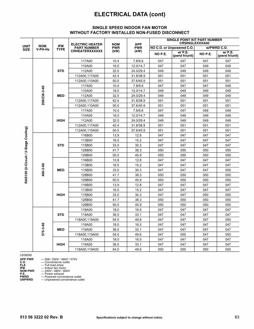
513 56 3222 02 Rev. B Specifications subject to change without notice. 83
LEGEND
SINGLE SPEED INDOOR FAN MOTORWITHOUT FACTORY INSTALLED NON-FUSED DISCONNECT
UNITSIZE
NOM.V-PH-Hz
IFMTYPE
ELECTRIC HEATERPART NUMBER
CRHEATERXXXXXX
NOMPWR(kW)
APPPWR(kW)
SINGLE POINT KIT PART NUMBERCRSINGLEXXXA00
NO C.O. or Unpowered C.O. w/PWRD C.O.
NO P.E. w/ P.E. (pwrd fr/unit) NO P.E. w/ P.E.
(pwrd fr/unit)
RA
S12
0 (2
-Cir
cuit
/ 2-
Sta
ge
Co
olin
g)
208/
230-
3-60
STD
117A00 10.4 7.8/9.6 047 047 047 047110A00 16.0 12.0/14.7 047 047 049 049112A00 32.0 24.0/29.4 049 049 049 049
112A00,117A00 42.4 31.8/38.9 051 051 051 051112A00,110A00 50.0 37.6/45.9 051 051 051 051
MED
117A00 10.4 7.8/9.6 047 047 047 049110A00 16.0 12.0/14.7 049 049 049 049112A00 32.0 24.0/29.4 049 049 049 049
112A00,117A00 42.4 31.8/38.9 051 051 051 051112A00,110A00 50.0 37.6/45.9 051 051 051 051
HIGH
117A00 10.4 7.8/9.6 047 047 049 049110A00 16.0 12.0/14.7 049 049 049 049112A00 32.0 24.0/29.4 049 049 049 049
112A00,117A00 42.4 31.8/38.9 051 051 051 051112A00,110A00 50.0 37.6/45.9 051 051 051 051
460-
3-60
STD
116B00 13.9 12.8 047 047 047 047113B00 16.5 15.2 047 047 047 047115B00 33.0 30.3 047 047 047 047128B00 41.7 38.3 050 050 050 050129B00 50.0 45.9 050 050 050 050
MED
116B00 13.9 12.8 047 047 047 047113B00 16.5 15.2 047 047 047 047115B00 33.0 30.3 047 047 047 050128B00 41.7 38.3 050 050 050 050129B00 50.0 45.9 050 050 050 050
HIGH
116B00 13.9 12.8 047 047 047 047113B00 16.5 15.2 047 047 047 047115B00 33.0 30.3 047 047 050 050128B00 41.7 38.3 050 050 050 050129B00 50.0 45.9 050 050 050 050
575-
3-60
STD118A00 18.0 16.5 047 047 047 047119A00 36.0 33.1 047 047 047 047
118A00,119A00 54.0 49.6 047 047 047 050
MED118A00 18.0 16.5 047 047 047 047119A00 36.0 33.1 047 047 047 047
118A00,119A00 54.0 49.6 047 050 047 050
HIGH118A00 18.0 16.5 047 047 047 047119A00 36.0 33.1 047 047 047 047
118A00,119A00 54.0 49.6 050 050 050 050
APP PWR — 208 / 230V / 460V / 575VC.O. — Convenience outletFLA — Full load ampsIFM — Indoor fan motorNOM PWR — 240V / 480V / 600VP.E. — Power exhaustPWRD — Powered convenience outletUNPWRD — Unpowered convenience outlet
ELECTRICAL DATA (cont)
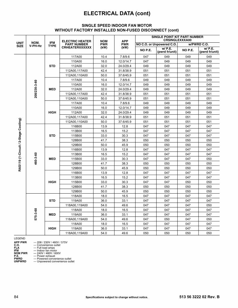
84 Specifications subject to change without notice. 513 56 3222 02 Rev. B
LEGEND
SINGLE SPEED INDOOR FAN MOTORWITHOUT FACTORY INSTALLED NON-FUSED DISCONNECT (cont)
UNITSIZE
NOM.V-PH-Hz
IFMTYPE
ELECTRIC HEATERPART NUMBER
CRHEATERXXXXXX
NOMPWR(kW)
APPPWR(kW)
SINGLE POINT KIT PART NUMBERCRSINGLEXXXA00
NO C.O. or Unpowered C.O. w/PWRD C.O.
NO P.E. w/ P.E. (pwrd fr/unit) NO P.E. w/ P.E.
(pwrd fr/unit)
RA
S11
9 (1
-Cir
cuit
/ 2-
Sta
ge
Co
olin
g)
208/
230-
3-60
STD
117A00 10.4 7.8/9.6 047 049 049 049110A00 16.0 12.0/14.7 047 049 049 049112A00 32.0 24.0/29.4 049 049 049 049
112A00,117A00 42.4 31.8/38.9 051 051 051 051112A00,110A00 50.0 37.6/45.9 051 051 051 051
MED
117A00 10.4 7.8/9.6 049 049 049 049110A00 16.0 12.0/14.7 049 049 049 049112A00 32.0 24.0/29.4 049 049 049 049
112A00,117A00 42.4 31.8/38.9 051 051 051 051112A00,110A00 50.0 37.6/45.9 051 051 051 051
HIGH
117A00 10.4 7.8/9.6 049 049 049 049110A00 16.0 12.0/14.7 049 049 049 049112A00 32.0 24.0/29.4 049 049 049 049
112A00,117A00 42.4 31.8/38.9 051 051 051 051112A00,110A00 50.0 37.6/45.9 051 051 051 051
460-
3-60
STD
116B00 13.9 12.8 047 047 047 047113B00 16.5 15.2 047 047 047 047115B00 33.0 30.3 047 047 047 047128B00 41.7 38.3 050 050 050 050129B00 50.0 45.9 050 050 050 050
MED
116B00 13.9 12.8 047 047 047 047113B00 16.5 15.2 047 047 047 047115B00 33.0 30.3 047 047 047 050128B00 41.7 38.3 050 050 050 050129B00 50.0 45.9 050 050 050 050
HIGH
116B00 13.9 12.8 047 047 047 047113B00 16.5 15.2 047 047 047 047115B00 33.0 30.3 047 047 050 050128B00 41.7 38.3 050 050 050 050129B00 50.0 45.9 050 050 050 050
575-
3-60
STD118A00 18.0 16.5 047 047 047 047119A00 36.0 33.1 047 047 047 047
118A00,119A00 54.0 49.6 047 047 047 050
MED118A00 18.0 16.5 047 047 047 047119A00 36.0 33.1 047 047 047 047
118A00,119A00 54.0 49.6 047 050 047 050
HIGH118A00 18.0 16.5 047 047 047 047119A00 36.0 33.1 047 047 047 047
118A00,119A00 54.0 49.6 050 050 050 050
APP PWR — 208 / 230V / 460V / 575VC.O. — Convenience outletFLA — Full load ampsIFM — Indoor fan motorNOM PWR — 240V / 480V / 600VP.E. — Power exhaustPWRD — Powered convenience outletUNPWRD — Unpowered convenience outlet
ELECTRICAL DATA (cont)

513 56 3222 02 Rev. B Specifications subject to change without notice. 85
LEGEND
SINGLE SPEED INDOOR FAN MOTORWITH FACTORY INSTALLED NON-FUSED DISCONNECT
UNITSIZE
NOM.V-PH-Hz
IFMTYPE
ELECTRIC HEATERPART NUMBER
CRHEATERXXXXXX
NOMPWR(kW)
APPPWR(kW)
SINGLE POINT KIT PART NUMBERCRSINGLEXXXA00
NO C.O. or Unpowered C.O. w/PWRD C.O.
NO P.E. w/ P.E. (pwrd fr/unit) NO P.E. w/ P.E.
(pwrd fr/unit)
RA
S12
0 (2
-Cir
cuit
/ 2-
Sp
eed
Co
olin
g)
208/
230-
3-60
STD
117A00 10.4 7.8/9.6 047 047 047 047110A00 16.0 12.0/14.7 047 047 049 049112A00 32.0 24.0/29.4 049 049 049 049
112A00,117A00 42.4 31.8/38.9 051 051 051 051112A00,110A00 50.0 37.6/45.9 051 051 051 051
MED
117A00 10.4 7.8/9.6 047 047 047 049110A00 16.0 12.0/14.7 049 049 049 049112A00 32.0 24.0/29.4 049 049 049 049
112A00,117A00 42.4 31.8/38.9 051 051 051 051112A00,110A00 50.0 37.6/45.9 051 051 051 051
HIGH
117A00 10.4 7.8/9.6 047 047 049 049110A00 16.0 12.0/14.7 049 049 049 049112A00 32.0 24.0/29.4 049 049 049 049
112A00,117A00 42.4 31.8/38.9 051 051 051 051112A00,110A00 50.0 37.6/45.9 051 051 051 051
460-
3-60
STD
116B00 13.9 12.8 047 047 047 047113B00 16.5 15.2 047 047 047 047115B00 33.0 30.3 047 047 047 047128B00 41.7 38.3 050 050 050 050129B00 50.0 45.9 050 050 050 050
MED
116B00 13.9 12.8 047 047 047 047113B00 16.5 15.2 047 047 047 047115B00 33.0 30.3 047 047 047 050128B00 41.7 38.3 050 050 050 050129B00 50.0 45.9 050 050 050 050
HIGH
116B00 13.9 12.8 047 047 047 047113B00 16.5 15.2 047 047 047 047115B00 33.0 30.3 047 047 050 050128B00 41.7 38.3 050 050 050 050129B00 50.0 45.9 050 050 050 050
575-
3-60
STD118A00 18.0 16.5 047 047 047 047119A00 36.0 33.1 047 047 047 047
118A00,119A00 54.0 49.6 047 047 047 050
MED118A00 18.0 16.5 047 047 047 047119A00 36.0 33.1 047 047 047 047
118A00,119A00 54.0 49.6 047 050 047 050
HIGH118A00 18.0 16.5 047 047 047 047119A00 36.0 33.1 047 047 047 047
118A00,119A00 54.0 49.6 050 050 050 050
APP PWR — 208 / 230V / 460V / 575VC.O. — Convenience outletFLA — Full load ampsIFM — Indoor fan motorNOM PWR — 240V / 480V / 600VP.E. — Power exhaustPWRD — Powered convenience outletUNPWRD — Unpowered convenience outlet
ELECTRICAL DATA (cont)

86 Specifications subject to change without notice. 513 56 3222 02 Rev. B
LEGEND
SINGLE SPEED INDOOR FAN MOTORWITH FACTORY INSTALLED NON-FUSED DISCONNECT (cont)
UNITSIZE
NOM.V-PH-Hz
IFMTYPE
ELECTRIC HEATERPART NUMBER
CRHEATERXXXXXX
NOMPWR(kW)
APPPWR(kW)
SINGLE POINT KIT PART NUMBERCRSINGLEXXXA00
NO C.O. or Unpowered C.O. w/PWRD C.O.
NO P.E. w/ P.E. (pwrd fr/unit) NO P.E. w/ P.E.
(pwrd fr/unit)
RA
S11
9 (1
-Cir
cuit
/ 2-
Sp
eed
Co
olin
g)
208/
230-
3-60
STD
117A00 10.4 7.8/9.6 047 049 049 049110A00 16.0 12.0/14.7 047 049 049 049112A00 32.0 24.0/29.4 049 049 049 049
112A00,117A00 42.4 31.8/38.9 051 051 051 051112A00,110A00 50.0 37.6/45.9 051 051 051 051
MED
117A00 10.4 7.8/9.6 049 049 049 049110A00 16.0 12.0/14.7 049 049 049 049112A00 32.0 24.0/29.4 049 049 049 049
112A00,117A00 42.4 31.8/38.9 051 051 051 051112A00,110A00 50.0 37.6/45.9 051 051 051 051
HIGH
117A00 10.4 7.8/9.6 049 049 049 049110A00 16.0 12.0/14.7 049 049 049 049112A00 32.0 24.0/29.4 049 049 049 049
112A00,117A00 42.4 31.8/38.9 051 051 051 051112A00,110A00 50.0 37.6/45.9 051 051 051 051
460-
3-60
STD
116B00 13.9 12.8 047 047 047 047113B00 16.5 15.2 047 047 047 047115B00 33.0 30.3 047 047 047 047128B00 41.7 38.3 050 050 050 050129B00 50.0 45.9 050 050 050 050
MED
116B00 13.9 12.8 047 047 047 047113B00 16.5 15.2 047 047 047 047115B00 33.0 30.3 047 047 047 050128B00 41.7 38.3 050 050 050 050129B00 50.0 45.9 050 050 050 050
HIGH
116B00 13.9 12.8 047 047 047 047113B00 16.5 15.2 047 047 047 047115B00 33.0 30.3 047 047 050 050128B00 41.7 38.3 050 050 050 050129B00 50.0 45.9 050 050 050 050
575-
3-60
STD118A00 18.0 16.5 047 047 047 047119A00 36.0 33.1 047 047 047 047
118A00,119A00 54.0 49.6 047 047 047 050
MED118A00 18.0 16.5 047 047 047 047119A00 36.0 33.1 047 047 047 047
118A00,119A00 54.0 49.6 047 050 047 050
HIGH118A00 18.0 16.5 047 047 047 047119A00 36.0 33.1 047 047 047 047
118A00,119A00 54.0 49.6 050 050 050 050
APP PWR — 208 / 230V / 460V / 575VC.O. — Convenience outletFLA — Full load ampsIFM — Indoor fan motorNOM PWR — 240V / 480V / 600VP.E. — Power exhaustPWRD — Powered convenience outletUNPWRD — Unpowered convenience outlet
ELECTRICAL DATA (cont)

513 56 3222 02 Rev. B Specifications subject to change without notice. 87
LEGEND
2-SPEED INDOOR FAN MOTORWITH OR WITHOUT FACTORY INSTALLED NON-FUSED DISCONNECT
UNITSIZE
NOM.V-PH-Hz
IFMTYPE
ELECTRIC HEATERPART NUMBER
CRHEATERXXXXXX
NOMPWR(kW)
APPPWR(kW)
SINGLE POINT KIT PART NUMBERCRSINGLEXXXA00
NO C.O. or Unpowered C.O. w/PWRD C.O.
NO P.E. w/ P.E. (pwrd fr/unit) NO P.E. w/ P.E.
(pwrd fr/unit)
RA
S12
0 (2
-Cir
cuit
/ 2-
Sta
ge
Co
olin
g)
208/
230-
3-60
STD
117A00 10.4 7.8/9.6 047 047 047 047110A00 16.0 12.0/14.7 047 049 049 049112A00 32.0 24.0/29.4 049 049 049 049
112A00,117A00 42.4 31.8/38.9 051 051 051 051112A00,110A00 50.0 37.6/45.9 051 051 051 051
MED
117A00 10.4 7.8/9.6 047 047 047 049110A00 16.0 12.0/14.7 049 049 049 049112A00 32.0 24.0/29.4 049 049 049 049
112A00,117A00 42.4 31.8/38.9 051 051 051 051112A00,110A00 50.0 37.6/45.9 051 051 051 051
HIGH
117A00 10.4 7.8/9.6 047 047 049 049110A00 16.0 12.0/14.7 049 049 049 049112A00 32.0 24.0/29.4 049 049 049 049
112A00,117A00 42.4 31.8/38.9 051 051 051 051112A00,110A00 50.0 37.6/45.9 051 051 051 051
460-
3-60
STD
116B00 13.9 12.8 047 047 047 047113B00 16.5 15.2 047 047 047 047115B00 33.0 30.3 047 047 047 047128B00 41.7 38.3 050 050 050 050129B00 50.0 45.9 050 050 050 050
MED
116B00 13.9 12.8 047 047 047 047113B00 16.5 15.2 047 047 047 047115B00 33.0 30.3 047 047 047 050128B00 41.7 38.3 050 050 050 050129B00 50.0 45.9 050 050 050 050
HIGH
116B00 13.9 12.8 047 047 047 047113B00 16.5 15.2 047 047 047 047115B00 33.0 30.3 047 047 050 050128B00 41.7 38.3 050 050 050 050129B00 50.0 45.9 050 050 050 050
575-
3-60
STD118A00 18.0 16.5 047 047 047 047119A00 36.0 33.1 047 047 047 047
118A00,119A00 54.0 49.6 047 050 047 050
MED118A00 18.0 16.5 047 047 047 047119A00 36.0 33.1 047 047 047 047
118A00,119A00 54.0 49.6 047 050 050 050
HIGH118A00 18.0 16.5 047 047 047 047119A00 36.0 33.1 047 047 047 047
118A00,119A00 54.0 49.6 050 050 050 050
APP PWR — 208 / 230V / 460V / 575VC.O. — Convenience outletFLA — Full load ampsIFM — Indoor fan motorNOM PWR — 240V / 480V / 600VP.E. — Power exhaustPWRD — Powered convenience outletUNPWRD — Unpowered convenience outlet
ELECTRICAL DATA (cont)

88 Specifications subject to change without notice. 513 56 3222 02 Rev. B
LEGEND
SINGLE SPEED INDOOR FAN MOTORWITHOUT FACTORY INSTALLED NON-FUSED DISCONNECT
UNITSIZE
NOM.V-PH-Hz
IFMTYPE
ELECTRIC HEATERPART NUMBER
CRHEATERXXXXXX
NOMPWR(kW)
APPPWR(kW)
SINGLE POINT KIT PART NUMBERCRSINGLEXXXA00
NO C.O. or Unpowered C.O. w/PWRD C.O.
NO P.E. w/ P.E. (pwrd fr/unit) NO P.E. w/ P.E.
(pwrd fr/unit)
RA
S15
0 (2
-Cir
cuit
/ 2-
Sp
eed
Co
olin
g)
208/
230-
3-60
STD
117A00 10.4 7.8/9.6 049 049 049 049110A00 16.0 12.0/14.7 049 049 049 049112A00 32.0 24.0/29.4 049 049 049 049
112A00,117A00 42.4 31.8/38.9 051 051 051 051112A00,110A00 50.0 37.6/45.9 051 051 051 051
MED
117A00 10.4 7.8/9.6 049 049 049 049110A00 16.0 12.0/14.7 049 049 049 049112A00 32.0 24.0/29.4 049 049 049 049
112A00,117A00 42.4 31.8/38.9 051 051 051 051112A00,110A00 50.0 37.6/45.9 051 051 051 051
HIGH
117A00 10.4 7.8/9.6 049 049 049 049110A00 16.0 12.0/14.7 049 049 049 049112A00 32.0 24.0/29.4 049 049 049 049
112A00,117A00 42.4 31.8/38.9 051 051 051 051112A00,110A00 50.0 37.6/45.9 051 051 051 051
460-
3-60
STD
116B00 13.9 12.8 047 047 047 047113B00 16.5 15.2 047 047 047 047115B00 33.0 30.3 047 047 047 047128B00 41.7 38.3 050 050 050 050129B00 50.0 45.9 050 050 050 050
MED
116B00 13.9 12.8 047 047 047 047113B00 16.5 15.2 047 047 047 047115B00 33.0 30.3 047 047 047 050128B00 41.7 38.3 050 050 050 050129B00 50.0 45.9 050 050 050 050
HIGH
116B00 13.9 12.8 047 047 047 047113B00 16.5 15.2 047 047 047 047115B00 33.0 30.3 047 047 050 050128B00 41.7 38.3 050 050 050 050129B00 50.0 45.9 050 050 050 050
575-
3-60
STD118A00 18.0 16.5 047 047 047 047119A00 36.0 33.1 047 047 047 047
118A00,119A00 54.0 49.6 047 050 047 050
MED118A00 18.0 16.5 047 047 047 047119A00 36.0 33.1 047 047 047 047
118A00,119A00 54.0 49.6 047 050 047 050
HIGH118A00 18.0 16.5 047 047 047 047119A00 36.0 33.1 047 047 047 047
118A00,119A00 54.0 49.6 050 050 050 050
APP PWR — 208 / 230V / 460V / 575VC.O. — Convenience outletFLA — Full load ampsIFM — Indoor fan motorNOM PWR — 240V / 480V / 600VP.E. — Power exhaustPWRD — Powered convenience outletUNPWRD — Unpowered convenience outlet
ELECTRICAL DATA (cont)

513 56 3222 02 Rev. B Specifications subject to change without notice. 89
LEGEND
SINGLE SPEED INDOOR FAN MOTORWITH FACTORY INSTALLED NON-FUSED DISCONNECT
UNITSIZE
NOM.V-PH-Hz
IFMTYPE
ELECTRIC HEATERPART NUMBER
CRHEATERXXXXXX
NOMPWR(kW)
APPPWR(kW)
SINGLE POINT KIT PART NUMBERCRSINGLEXXXA00
NO C.O. or Unpowered C.O. w/PWRD C.O.
NO P.E. w/ P.E. (pwrd fr/unit) NO P.E. w/ P.E.
(pwrd fr/unit)
RA
S15
0 (2
-Cir
cuit
/ 2-
Sta
ge
Co
olin
g)
208/
230-
3-60
STD
117A00 10.4 7.8/9.6 049 049 049 049110A00 16.0 12.0/14.7 049 049 049 049112A00 32.0 24.0/29.4 049 049 049 049
112A00,117A00 42.4 31.8/38.9 051 051 051 051112A00,110A00 50.0 37.6/45.9 051 051 051 051
MED
117A00 10.4 7.8/9.6 049 049 049 049110A00 16.0 12.0/14.7 049 049 049 049112A00 32.0 24.0/29.4 049 049 049 049
112A00,117A00 42.4 31.8/38.9 051 051 051 051112A00,110A00 50.0 37.6/45.9 051 051 051 051
HIGH
117A00 10.4 7.8/9.6 049 049 049 049110A00 16.0 12.0/14.7 049 049 049 049112A00 32.0 24.0/29.4 049 049 049 049
112A00,117A00 42.4 31.8/38.9 051 051 051 051112A00,110A00 50.0 37.6/45.9 051 051 051 051
460-
3-60
STD
116B00 13.9 12.8 047 047 047 047113B00 16.5 15.2 047 047 047 047115B00 33.0 30.3 047 047 047 047128B00 41.7 38.3 050 050 050 050129B00 50.0 45.9 050 050 050 050
MED
116B00 13.9 12.8 047 047 047 047113B00 16.5 15.2 047 047 047 047115B00 33.0 30.3 047 047 047 050128B00 41.7 38.3 050 050 050 050129B00 50.0 45.9 050 050 050 050
HIGH
116B00 13.9 12.8 047 047 047 047113B00 16.5 15.2 047 047 047 047115B00 33.0 30.3 047 047 050 050128B00 41.7 38.3 050 050 050 050129B00 50.0 45.9 050 050 050 050
575-
3-60
STD118A00 18.0 16.5 047 047 047 047119A00 36.0 33.1 047 047 047 047
118A00,119A00 54.0 49.6 047 050 047 050
MED118A00 18.0 16.5 047 047 047 047119A00 36.0 33.1 047 047 047 047
118A00,119A00 54.0 49.6 047 050 047 050
HIGH118A00 18.0 16.5 047 047 047 047119A00 36.0 33.1 047 047 047 047
118A00,119A00 54.0 49.6 050 050 050 050
APP PWR — 208 / 230V / 460V / 575VC.O. — Convenience outletFLA — Full load ampsIFM — Indoor fan motorNOM PWR — 240V / 480V / 600VP.E. — Power exhaustPWRD — Powered convenience outletUNPWRD — Unpowered convenience outlet
ELECTRICAL DATA (cont)

90 Specifications subject to change without notice. 513 56 3222 02 Rev. B
LEGEND
COOLING 2-SPEED INDOOR FAN MOTOR WITH OR WITHOUT FACTORY INSTALLED NON-FUSED DISCONNECT
UNITSIZE
NOM.V-PH-Hz
IFMTYPE
ELECTRIC HEATERPART NUMBER
CRHEATERXXXXXX
NOMPWR(kW)
APPPWR(kW)
SINGLE POINT KIT PART NUMBERCRSINGLEXXXA00
NO C.O. or Unpowered C.O. w/PWRD C.O.
NO P.E. w/ P.E. (pwrd fr/unit) NO P.E. w/ P.E.
(pwrd fr/unit)
RA
S15
0 (2
-Cir
cuit
/ 2-
Sta
ge
Co
olin
g)
208/
230-
3-60
STD
117A00 10.4 7.8/9.6 049 049 049 049110A00 16.0 12.0/14.7 049 049 049 049112A00 32.0 24.0/29.4 049 049 049 049
112A00,117A00 42.4 31.8/38.9 051 051 051 051112A00,110A00 50.0 37.6/45.9 051 051 051 051
MED
117A00 10.4 7.8/9.6 049 049 049 049110A00 16.0 12.0/14.7 049 049 049 049112A00 32.0 24.0/29.4 049 049 049 049
112A00,117A00 42.4 31.8/38.9 051 051 051 051112A00,110A00 50.0 37.6/45.9 051 051 051 051
HIGH
117A00 10.4 7.8/9.6 049 049 049 049110A00 16.0 12.0/14.7 049 049 049 049112A00 32.0 24.0/29.4 049 049 049 049
112A00,117A00 42.4 31.8/38.9 051 051 051 051112A00,110A00 50.0 37.6/45.9 051 051 051 051
460-
3-60
STD
116B00 13.9 12.8 047 047 047 047113B00 16.5 15.2 047 047 047 047115B00 33.0 30.3 047 047 047 047128B00 41.7 38.3 050 050 050 050129B00 50.0 45.9 050 050 050 050
MED
116B00 13.9 12.8 047 047 047 047113B00 16.5 15.2 047 047 047 047115B00 33.0 30.3 047 047 047 050128B00 41.7 38.3 050 050 050 050129B00 50.0 45.9 050 050 050 050
HIGH
116B00 13.9 12.8 047 047 047 047113B00 16.5 15.2 047 047 047 047115B00 33.0 30.3 047 047 050 050128B00 41.7 38.3 050 050 050 050129B00 50.0 45.9 050 050 050 050
575-
3-60
STD118A00 18.0 16.5 047 047 047 047119A00 36.0 33.1 047 047 047 047
118A00,119A00 54.0 49.6 047 050 050 050
MED118A00 18.0 16.5 047 047 047 047119A00 36.0 33.1 047 047 047 047
118A00,119A00 54.0 49.6 047 050 050 050
HIGH118A00 18.0 16.5 047 047 047 047119A00 36.0 33.1 047 047 047 047
118A00,119A00 54.0 49.6 050 050 050 050
APP PWR — 208 / 230V / 460V / 575VC.O. — Convenience outletFLA — Full load ampsIFM — Indoor fan motorNOM PWR — 240V / 480V / 600VP.E. — Power exhaustPWRD — Powered convenience outletUNPWRD — Unpowered convenience outlet
ELECTRICAL DATA (cont)

513 56 3222 02 Rev. B Specifications subject to change without notice. 91
LEGEND
SINGLE SPEED INDOOR FAN MOTORWITHOUT FACTORY INSTALLED NON-FUSED DISCONNECT
UNITSIZE
NOM.V-PH-Hz
IFMTYPE
ELECTRIC HEATERPART NUMBER
CRHEATERXXXXXX
NOMPWR(kW)
APPPWR(kW)
SINGLE POINT KIT PART NUMBERCRSINGLEXXXA00
NO C.O. or Unpowered C.O. w/PWRD C.O.
NO P.E. w/ P.E. (pwrd fr/unit) NO P.E. w/ P.E.
(pwrd fr/unit)
RA
S18
0 (2
-Cir
cuit
/ 2-
Sta
ge
Co
olin
g)
208/
230-
3-60
STD
291A00 16.5 12.4/15.2 049 049 049 049294A00 33.5 25.2/30.8 049 049 049 049
288A00,294A00 43.5 32.7/40.0 051 051 051 051291A00,294A00 50.0 37.6/45.9 051 051 051 051294A00,294A00 67.0 50.3/61.5 053 053 053 053
MED
291A00 16.5 12.4/15.2 049 049 049 049294A00 33.5 25.2/30.8 049 049 049 049
288A00,294A00 43.5 32.7/40.0 051 051 051 051291A00,294A00 50.0 37.6/45.9 051 051 051 051294A00,294A00 67.0 50.3/61.5 053 053 053 053
HIGH
291A00 16.5 12.4/15.2 049 049 049 049294A00 33.5 25.2/30.8 049 049 049 049
288A00,294A00 43.5 32.7/40.0 051 051 051 051291A00,294A00 50.0 37.6/45.9 051 051 051 051294A00,294A00 67.0 50.3/61.5 053 053 053 053
460-
3-60
STD
292A00 16.5 15.2 — — — —295A00 33.5 30.8 047 047 047 050
289A00,295A00 43.5 40.0 050 050 050 050292A00,295A00 50.0 45.9 050 050 050 050295A00,295A00 67.0 61.5 050 050 050 050
MED
292A00 16.5 15.2 — — — —295A00 33.5 30.8 047 047 047 050
289A00,295A00 43.5 40.0 050 050 050 050292A00,295A00 50.0 45.9 050 050 050 050295A00,295A00 67.0 61.5 050 050 050 050
HIGH
292A00 16.5 15.2 — — — —295A00 33.5 30.8 050 050 050 050
289A00,295A00 43.5 40.0 050 050 050 050292A00,295A00 50.0 45.9 050 050 050 050295A00,295A00 67.0 61.5 050 050 050 050
575-
3-60
STD
293A00 16.5 15.2 — — — —
296A00 33.5 30.8 047 047 047 047290A00,296A00 43.5 40.0 047 050 047 050293A00,296A00 50.0 45.9 047 047 047 047296A00,296A00 67.0 61.5 050 050 050 050
MED
293A00 16.5 15.2 — — — —
296A00 33.5 30.8 047 047 047 047290A00,296A00 43.5 40.0 047 050 047 050293A00,296A00 50.0 45.9 047 047 047 047296A00,296A00 67.0 61.5 050 050 050 050
HIGH
293A00 16.5 15.2 — — — —
296A00 33.5 30.8 047 047 047 047290A00,296A00 43.5 40.0 050 050 050 050293A00,296A00 50.0 45.9 050 050 047 050296A00,296A00 67.0 61.5 050 050 050 050
APP PWR — 208 / 230V / 460V / 575VC.O. — Convenience outletFLA — Full load ampsIFM — Indoor fan motorNOM PWR — 240V / 480V / 600VP.E. — Power exhaustPWRD — Powered convenience outletUNPWRD — Unpowered convenience outlet
ELECTRICAL DATA (cont)

92 Specifications subject to change without notice. 513 56 3222 02 Rev. B
LEGEND
SINGLE SPEED INDOOR FAN MOTORWITH FACTORY INSTALLED NON-FUSED DISCONNECT
UNITSIZE
NOM.V-PH-Hz
IFMTYPE
ELECTRIC HEATERPART NUMBER
CRHEATERXXXXXX
NOMPWR(kW)
APPPWR(kW)
SINGLE POINT KIT PART NUMBERCRSINGLEXXXA00
NO C.O. or Unpowered C.O. w/PWRD C.O.
NO P.E. w/ P.E. (pwrd fr/unit) NO P.E. w/ P.E.
(pwrd fr/unit)
RA
S18
0 (2
-Cir
cuit
/ 2-
Sta
ge
Co
olin
g)
208/
230-
3-60
STD
291A00 16.5 12.4/15.2 049 049 049 049294A00 33.5 25.2/30.8 049 049 049 049
288A00,294A00 43.5 32.7/40.0 051 051 051 051291A00,294A00 50.0 37.6/45.9 051 051 051 051294A00,294A00 67.0 50.3/61.5 053 053 053 053
MED
291A00 16.5 12.4/15.2 049 049 049 049294A00 33.5 25.2/30.8 049 049 049 049
288A00,294A00 43.5 32.7/40.0 051 051 051 051291A00,294A00 50.0 37.6/45.9 051 051 051 051294A00,294A00 67.0 50.3/61.5 053 053 053 053
HIGH
291A00 16.5 12.4/15.2 049 049 049 049294A00 33.5 25.2/30.8 049 049 049 049
288A00,294A00 43.5 32.7/40.0 051 051 051 051291A00,294A00 50.0 37.6/45.9 051 051 051 051294A00,294A00 67.0 50.3/61.5 053 053 053 053
460-
3-60
STD
292A00 16.5 15.2 — — — —
295A00 33.5 30.8 047 047 047 050289A00,295A00 43.5 40.0 050 050 050 050292A00,295A00 50.0 45.9 050 050 050 050295A00,295A00 67.0 61.5 050 050 050 050
MED
292A00 16.5 15.2 — — — —
295A00 33.5 30.8 047 047 047 050289A00,295A00 43.5 40.0 050 050 050 050292A00,295A00 50.0 45.9 050 050 050 050295A00,295A00 67.0 61.5 050 050 050 050
HIGH
292A00 16.5 15.2 — — — —
295A00 33.5 30.8 050 050 050 050289A00,295A00 43.5 40.0 050 050 050 050292A00,295A00 50.0 45.9 050 050 050 050295A00,295A00 67.0 61.5 050 050 050 050
575-
3-60
STD
293A00 16.5 15.2 — — — —
296A00 33.5 30.8 047 047 047 047290A00,296A00 43.5 40.0 047 050 047 050293A00,296A00 50.0 45.9 047 047 047 047296A00,296A00 67.0 61.5 050 050 050 050
MED
293A00 16.5 15.2 — — — —
296A00 33.5 30.8 047 047 047 047290A00,296A00 43.5 40.0 047 050 047 050293A00,296A00 50.0 45.9 047 047 047 047296A00,296A00 67.0 61.5 050 050 050 050
HIGH
293A00 16.5 15.2 — — — —
296A00 33.5 30.8 047 047 047 047290A00,296A00 43.5 40.0 050 050 050 050293A00,296A00 50.0 45.9 050 050 047 050296A00,296A00 67.0 61.5 050 050 050 050
APP PWR — 208 / 230V / 460V / 575VC.O. — Convenience outletFLA — Full load ampsIFM — Indoor fan motorNOM PWR — 240V / 480V / 600VP.E. — Power exhaustPWRD — Powered convenience outletUNPWRD — Unpowered convenience outlet
ELECTRICAL DATA (cont)

513 56 3222 02 Rev. B Specifications subject to change without notice. 93
LEGEND
2-SPEED INDOOR FAN MOTORWITH OR WITHOUT FACTORY INSTALLED NON-FUSED DISCONNECT
UNITSIZE
NOM.V-PH-Hz
IFMTYPE
ELECTRIC HEATERPART NUMBER
CRHEATERXXXXXX
NOMPWR(kW)
APPPWR(kW)
SINGLE POINT KIT PART NUMBERCRSINGLEXXXA00
NO C.O. or Unpowered C.O. w/PWRD C.O.
NO P.E. w/ P.E. (pwrd fr/unit) NO P.E. w/ P.E.
(pwrd fr/unit)
RA
S18
0 (2
-Cir
cuit
/ 2-
Sta
ge
Co
olin
g)
208/
230-
3-60
STD
291A00 16.5 12.4/15.2 049 049 049 049294A00 33.5 25.2/30.8 049 049 049 049
288A00,294A00 43.5 32.7/40.0 051 051 051 051291A00,294A00 50.0 37.6/45.9 051 051 051 051294A00,294A00 67.0 50.3/61.5 053 053 053 053
MED
291A00 16.5 12.4/15.2 049 049 049 049294A00 33.5 25.2/30.8 049 049 049 049
288A00,294A00 43.5 32.7/40.0 051 051 051 051291A00,294A00 50.0 37.6/45.9 051 051 051 051294A00,294A00 67.0 50.3/61.5 053 053 053 053
HIGH
291A00 16.5 12.4/15.2 049 049 049 049294A00 33.5 25.2/30.8 049 049 049 049
288A00,294A00 43.5 32.7/40.0 051 051 051 051291A00,294A00 50.0 37.6/45.9 051 051 051 051294A00,294A00 67.0 50.3/61.5 053 053 053 053
460-
3-60
STD
292A00 16.5 15.2 — — — —
295A00 33.5 30.8 047 047 047 050289A00,295A00 43.5 40.0 050 050 050 050292A00,295A00 50.0 45.9 050 050 050 050295A00,295A00 67.0 61.5 050 050 050 050
MED
292A00 16.5 15.2 — — — —
295A00 33.5 30.8 047 047 047 050289A00,295A00 43.5 40.0 050 050 050 050292A00,295A00 50.0 45.9 050 050 050 050295A00,295A00 67.0 61.5 050 050 050 050
HIGH
292A00 16.5 15.2 — — — —
295A00 33.5 30.8 050 050 050 050289A00,295A00 43.5 40.0 050 050 050 050292A00,295A00 50.0 45.9 050 050 050 050295A00,295A00 67.0 61.5 050 050 050 050
575-
3-60
STD
293A00 16.5 15.2 — — — —
296A00 33.5 30.8 047 047 047 047290A00,296A00 43.5 40.0 047 050 050 050293A00,296A00 50.0 45.9 047 047 047 050296A00,296A00 67.0 61.5 050 050 050 050
MED
293A00 16.5 15.2 — — — —
296A00 33.5 30.8 047 047 047 047290A00,296A00 43.5 40.0 047 050 050 050293A00,296A00 50.0 45.9 047 047 047 050296A00,296A00 67.0 61.5 050 050 050 050
HIGH
293A00 16.5 15.2 — — — —
296A00 33.5 30.8 047 047 047 047290A00,296A00 43.5 40.0 050 050 050 050293A00,296A00 50.0 45.9 050 050 050 050296A00,296A00 67.0 61.5 050 050 050 050
APP PWR — 208 / 230V / 460V / 575VC.O. — Convenience outletFLA — Full load ampsIFM — Indoor fan motorNOM PWR — 240V / 480V / 600VP.E. — Power exhaustPWRD — Powered convenience outletUNPWRD — Unpowered convenience outlet
ELECTRICAL DATA (cont)

94 Specifications subject to change without notice. 513 56 3222 02 Rev. B
See Legend and Notes on page 65.
UNIT WIRE/FUSE OR HACR BREAKER SIZING DATA—1-SPEED INDOOR FAN MOTOR, 6 TONS
SIZE
/STA
GE
NO
M. V
-Ph-
Hz
IFMTYPE
ELECTRIC HEATER NO CONVENIENCE OUTLET (C.O). or UNPWR C.O.
CRHEATER***A00 Nom (kW) FLA
NO Power Exhaust (P.E.) w/ P.E. (pwrd fr/ unit)
MCAFuse or
Hacr Brkr
DISC. SIZE
MCAFuse or
Hacr Brkr
DISC. SIZE
FLA LRA FLA LRA
RA
S07
2 (1
-Cir
cuit
/ 1-
Sta
ge
Co
ol)
208/
230-
3-60
STD
NONE — — 32 50 30 170 34 50 32 172102A 4.9/6.5 13.6/15.6 32/32 50/50 30/30 170/170 34/34 50/50 32/32 172/172104B 7.9/10.5 21.9/25.3 34/39 50/50 31/35 170/170 37/41 50/50 33/37 172/172105A 12.0/16.0 33.4/38.5 49/55 50/60 44/50 170/170 51/57 60/60 47/52 172/172
104B+104B 15.8/21.0 43.8/50.5 62/70 70/70 56/64 170/170 64/72 70/80 59/66 172/172104B+105A 19.9/26.5 55.2/63.8 76/87 80/90 69/79 170/170 78/89 80/90 72/82 172/172
MED
NONE — — 35/35 50/50 34/34 212 37/37 50/50 36/36 214102A 4.9/6.5 13.6/15.6 35/35 50/50 34/34 212/212 37/37 50/50 36/36 214/214104B 7.9/10.5 21.9/25.3 38/42 50/50 35/39 212/212 41/45 50/50 37/41 214/214105A 12.0/16.0 33.4/38.5 53/59 60/60 48/54 212/212 55/61 60/70 50/56 214/214
104B+104B 15.8/21.0 43.8/50.5 66/74 70/80 60/68 212/212 68/76 70/80 62/70 214/214104B+105A 19.9/26.5 55.2/63.8 80/91 80/100 73/83 212/212 82/93 90/100 75/85 214/214
HIGH
NONE — — 37 50 36 226 39 50 39 228102A 4.9/6.5 13.6/15.6 37/37 50/50 36/36 226/226 39/39 50/50 39/39 228/228104B 7.9/10.5 21.9/25.3 41/45 50/50 37/41 226/226 43/48 50/50 40/43 228/228105A 12.0/16.0 33.4/38.5 55/62 60/70 51/56 226/226 58/64 60/70 53/59 228/228
104B+104B 15.8/21.0 43.8/50.5 68/77 70/80 63/70 226/226 71/79 80/80 65/72 228/228104B+105A 19.9/26.5 55.2/63.8 83/93 90/100 76/86 226/226 85/96 90/100 78/88 228/228
460-
3-60
STD
NONE — — 14 20 13 83 15 20 14 84106A 6.0 7.2 14 20 13 83 15 20 14 84108A 11.5 13.8 21 25 19 83 22 25 20 84109A 14.0 16.8 25 25 22 83 26 30 23 84
108A+108A 23.0 27.7 38 40 35 83 40 40 36 84108A+109A 25.5 30.7 42 45 38 83 43 45 39 84
MED
NONE — — 16 20 15 104 17 20 16 105106A 6.0 7.2 16 20 15 104 17 20 16 105108A 11.5 13.8 23 25 21 104 24 25 22 105109A 14.0 16.8 27 30 24 104 28 30 25 105
108A+108A 23.0 27.7 40 40 37 104 42 45 38 105108A+109A 25.5 30.7 44 45 40 104 45 45 41 105
HIGH
NONE — — 17 20 16 111 18 25 18 112106A 6.0 7.2 17 20 16 111 18 25 18 112108A 11.5 13.8 24 25 22 111 26 30 23 112109A 14.0 16.8 28 30 25 111 29 30 27 112
108A+108A 23.0 27.7 42 45 38 111 43 45 39 112108A+109A 25.5 30.7 45 50 41 111 47 50 43 112
575-
3-60 STD NONE — — 11 15 11 68 13 15 13 70
MED NONE — — 12 15 12 79 14 20 14 81
HIGH NONE — — 12 15 12 79 14 20 14 81
ELECTRICAL DATA (cont)

513 56 3222 02 Rev. B Specifications subject to change without notice. 95
See Legend and Notes on page 65.
UNIT WIRE/FUSE OR HACR BREAKER SIZING DATA — 1-SPEED INDOOR FAN MOTOR, 6 TONS (cont)SI
ZE/S
TAG
E
NO
M. V
-Ph-
Hz
IFMTYPE
ELECTRIC HEATER w/ PWRD C.O.
CRHEATER***A00 Nom (kW) FLA
NO P.E. w/ P.E. (pwrd fr/ unit)
MCAFuse or
Hacr Brkr
DISC. SIZE
MCAFuse or
Hacr Brkr
DISC. SIZE
FLA LRA FLA LRA
RA
S07
2 (1
-Cir
cuit
/ 1-
Sta
ge
Co
ol)
208/
230-
3-60
STD
NONE — — 36 50 36 175 38 50 38 177102A 4.9/6.5 13.6/15.6 36/36 50/50 36/36 175/175 38/38 50/50 38/38 177/177104B 7.9/10.5 21.9/25.3 40/45 50/50 37/41 175/175 43/47 50/50 39/43 177/177105A 12.0/16.0 33.4/38.5 55/61 60/70 50/56 175/175 57/63 60/70 52/58 177/177
104B+104B 15.8/21.0 43.8/50.5 68/76 70/80 62/70 175/175 70/78 70/80 64/72 177/177104B+105A 19.9/26.5 55.2/63.8 82/93 90/100 75/85 175/175 84/95 90/100 77/87 177/177
MED
NONE — — 40/40 50/50 39/39 217 42/41 60/60 42/42 219102A 4.9/6.5 13.6/15.6 40/40 50/50 39/39 217/217 42/41 60/60 42/42 219/219104B 7.9/10.5 21.9/25.3 44/48 50/50 40/44 217/217 47/51 60/60 43/46 219/219105A 12.0/16.0 33.4/38.5 59/65 60/70 54/59 217/217 61/67 70/70 56/62 219/219
104B+104B 15.8/21.0 43.8/50.5 72/80 80/80 66/73 217/217 74/82 80/90 68/75 219/219104B+105A 19.9/26.5 55.2/63.8 86/97 90/100 79/88 217/217 88/99 90/100 81/91 219/219
HIGH
NONE — — 42 60 42 231 44 60 44 233102A 4.9/6.5 13.6/15.6 42/42 60/60 42/42 231/231 44/44 60/60 44/44 233/233104B 7.9/10.5 21.9/25.3 47/51 60/60 43/47 231/231 49/54 60/60 45/49 233/233105A 12.0/16.0 33.4/38.5 61/68 70/70 56/62 231/231 64/70 70/70 58/64 233/233
104B+104B 15.8/21.0 43.8/50.5 74/83 80/90 68/76 231/231 77/85 80/90 70/78 233/233104B+105A 19.9/26.5 55.2/63.8 89/99 90/100 81/91 231/231 91/102 100/110 83/93 233/233
460-
3-60
STD
NONE — — 16 20 16 85 17 25 17 86106A 6.0 7.2 16 20 16 85 17 25 17 86108A 11.5 13.8 24 25 21 85 25 25 23 86109A 14.0 16.8 27 30 25 85 29 30 26 86
108A+108A 23.0 27.7 41 45 37 85 42 45 39 86108A+109A 25.5 30.7 45 45 41 85 46 50 42 86
MED
NONE — — 18 25 18 106 19 25 19 107106A 6.0 7.2 18 25 18 106 19 25 19 107108A 11.5 13.8 26 30 23 106 27 30 24 107109A 14.0 16.8 29 30 27 106 31 35 28 107
108A+108A 23.0 27.7 43 45 39 106 44 45 40 107108A+109A 25.5 30.7 47 50 43 106 48 50 44 107
HIGH
NONE — — 19 25 19 113 20 25 20 114106A 6.0 7.2 19 25 19 113 20 25 20 114108A 11.5 13.8 27 30 24 113 28 30 26 114109A 14.0 16.8 31 35 28 113 32 35 29 114
108A+108A 23.0 27.7 44 45 40 113 46 50 42 114108A+109A 25.5 30.7 48 50 44 113 49 50 45 114
575-
3-60 STD NONE — — 13 15 13 70 15 20 15 72
MED NONE — — 14 15 13 81 16 20 16 83
HIGH NONE — — 14 15 13 81 16 20 16 83
ELECTRICAL DATA (cont)

96 Specifications subject to change without notice. 513 56 3222 02 Rev. B
UNIT WIRE/FUSE OR HACR BREAKER SIZING DATA—1-SPEED INDOOR FAN MOTOR, 7.5 TONS
SIZ
E/S
TA
GE
NO
M. V
-Ph
-Hz
IFMTYPE
ELECTRIC HEATER NO CONVENIENCE OUTLET (C.O). or UNPWR C.O.
CRHEATER***A00 Nom (kW) FLA
NO Power Exhaust (P.E.) w/ P.E. (pwrd fr/ unit)
MCAFuse or
Hacr Brkr
DISC. SIZE
MCAFuse or
Hacr Brkr
DISC. SIZE
FLA LRA FLA LRA
RA
S09
0 (2
-Cir
cuit
/ 2-
Sta
ge
Co
olin
g)
208/
230-
3-60
STD
NONE — — 39/39 50/50 41/40 210 43/43 50/50 45/45 214117A 7.8/10.4 21.7/25.0 39/39 50/50 41/40 210/210 43/43 50/50 45/45 214/214110A 12.0/16.0 33.4/38.5 49/55 50/60 44/50 210/210 53/59 60/60 49/54 214/214111A 18.6/24.8 51.7/59.7 72/81 80/90 65/74 210/210 76/86 80/90 70/79 214/214112A 24.0/32.0 66.7/77.0 90/103 90/110 83/94 210/210 95/108 100/110 87/99 214/214
112A+117A 31.8/42.4 88.4/102.0 117/134 125/150 108/123 210/210 122/139 125/150 112/127 214/214
MED
NONE — — 42/42 50/50 44/44 246 46/46 50/50 49/49 250117A 7.8/10.4 21.7/25.0 42/42 50/50 44/44 246/246 46/47 50/50 49/49 250/250110A 12.0/16.0 33.4/38.5 53/59 60/60 48/54 246/246 57/64 60/70 52/58 250/250111A 18.6/24.8 51.7/59.7 76/85 80/90 69/78 246/246 80/90 80/90 73/83 250/250112A 24.0/32.0 66.7/77.0 94/107 100/110 86/98 246/246 99/112 100/125 91/102 250/250
112A+117A 31.8/42.4 88.4/102.0 121/138 125/150 111/127 246/246 126/143 150/150 116/131 250/250
HIGH
NONE — — 48/47 60/50 50/49 262 51/51 60/60 55/54 266117A 7.8/10.4 21.7/25.0 48/48 60/50 50/49 262/262 51/52 60/60 55/54 266/266110A 12.0/16.0 33.4/38.5 59/64 60/70 54/59 262/262 64/69 70/70 58/63 266/266111A 18.6/24.8 51.7/59.7 82/91 90/100 75/83 262/262 87/96 90/100 79/88 266/266112A 24.0/32.0 66.7/77.0 101/113 110/125 92/103 262/262 106/117 110/125 97/108 266/266
112A+117A 31.8/42.4 88.4/102.0 128/144 150/150 117/132 262/262 133/149 150/150 122/136 266/266
460-
3-60
STD
NONE — — 18 20 19 104 20 25 21 106116B 13.9 16.7 24 25 22 104 27 30 24 106113B 16.5 19.8 28 30 26 104 31 35 28 106114B 27.8 33.4 45 45 41 104 48 50 43 106115B 33.0 39.7 53 60 49 104 55 60 51 106128B 41.7 50.2 66 70 61 104 69 70 63 106
MED
NONE — — 20 25 21 122 22 25 23 124116B 13.9 16.7 27 30 24 122 29 30 26 124113B 16.5 19.8 30 30 28 122 33 35 30 124114B 27.8 33.4 47 50 43 122 50 50 45 124115B 33.0 39.7 55 60 50 122 58 60 53 124128B 41.7 50.2 68 70 63 122 71 80 65 124
HIGH
NONE — — 22 25 23 130 24 30 25 132116B 13.9 16.7 29 30 27 130 32 35 29 132113B 16.5 19.8 33 35 30 130 35 35 32 132114B 27.8 33.4 50 50 46 130 52 60 48 132115B 33.0 39.7 58 60 53 130 60 60 55 132128B 41.7 50.2 71 80 65 130 73 80 67 132
575-
3-60
STDNONE — — 14 15 14 85 18 20 19 89118A 18.0 17.3 26 30 23 85 30 30 27 89119A 36.0 34.6 47 50 43 85 52 60 47 89
MEDNONE — — 14 15 14 92 18 20 19 96118A 18.0 17.3 26 30 23 92 30 30 27 96119A 36.0 34.6 47 50 43 92 52 60 47 96
HIGHNONE — — 17 20 17 106 21 25 22 110118A 18.0 17.3 29 30 26 106 34 35 31 110119A 36.0 34.6 51 60 46 106 55 60 51 110
See Legend and Notes on page 65.
ELECTRICAL DATA (cont)

513 56 3222 02 Rev. B Specifications subject to change without notice. 97
UNIT WIRE/FUSE OR HACR BREAKER SIZING DATA—1-SPEED INDOOR FAN MOTOR, 7.5 TONS (cont)S
IZE
/ST
AG
E
NO
M. V
-Ph
-Hz
IFMTYPE
ELECTRIC HEATER w/ PWRD C.O.
CRHEATER***A00 Nom (kW) FLA
NO P.E. w/ P.E. (pwrd fr/ unit)
MCAFuse or
Hacr Brkr
DISC. SIZE
MCAFuse or
Hacr Brkr
DISC. SIZE
FLA LRA FLA LRA
RA
S09
0 (2
-Cir
cuit
/ 2-
Sta
ge
Co
olin
g)
208/
230-
3-60
STD
NONE — — 44/44 50/50 46/46 215 48/48 60/60 51/50 219117A 7.8/10.4 21.7/25.0 44/44 50/50 46/46 215/215 48/49 60/60 51/50 219/219110A 12.0/16.0 33.4/38.5 55/61 60/70 50/55 215/215 59/65 60/70 54/60 219/219111A 18.6/24.8 51.7/59.7 78/87 80/90 71/80 215/215 82/92 90/100 75/84 219/219112A 24.0/32.0 66.7/77.0 96/109 100/110 88/100 215/215 101/114 110/125 93/104 219/219
112A+117A 31.8/42.4 88.4/102.0 123/140 125/150 113/128 215/215 128/145 150/150 118/133 219/219
MED
NONE — — 47/47 60/60 50/50 251 51/51 60/60 54/54 255117A 7.8/10.4 21.7/25.0 47/48 60/60 50/50 251/251 51/53 60/60 54/54 255/255110A 12.0/16.0 33.4/38.5 59/65 60/70 54/59 251/251 63/70 70/70 58/64 255/255111A 18.6/24.8 51.7/59.7 82/91 90/100 75/84 251/251 86/96 90/100 79/88 255/255112A 24.0/32.0 66.7/77.0 100/113 100/125 92/104 251/251 105/118 110/125 96/108 255/255
112A+117A 31.8/42.4 88.4/102.0 127/144 150/150 117/132 251/251 132/149 150/150 121/137 255/255
HIGH
NONE — — 52/52 60/60 56/55 267 56/55 60/60 60/59 271117A 7.8/10.4 21.7/25.0 52/54 60/60 56/55 267/267 56/58 60/60 60/59 271/271110A 12.0/16.0 33.4/38.5 65/70 70/70 60/64 267/267 70/75 70/80 64/69 271/271111A 18.6/24.8 51.7/59.7 88/97 90/100 81/89 267/267 93/102 100/110 85/93 271/271112A 24.0/32.0 66.7/77.0 107/119 110/125 98/109 267/267 112/123 125/125 102/113 271/271
112A+117A 31.8/42.4 88.4/102.0 134/150 150/150 123/137 267/267 139/155 150/175 127/142 271/271
460-
3-60
STD
NONE — — 20 25 21 106 22 25 23 108116B 13.9 16.7 27 30 25 106 29 30 27 108113B 16.5 19.8 31 35 28 106 33 35 30 108114B 27.8 33.4 48 50 44 106 50 50 46 108115B 33.0 39.7 56 60 51 106 58 60 53 108128B 41.7 50.2 69 70 63 106 71 80 65 108
MED
NONE — — 22 25 23 124 24 30 25 126116B 13.9 16.7 29 30 27 124 32 35 29 126113B 16.5 19.8 33 35 30 124 35 40 32 126114B 27.8 33.4 50 50 46 124 52 60 48 126115B 33.0 39.7 58 60 53 124 60 60 55 126128B 41.7 50.2 71 80 65 124 73 80 67 126
HIGH
NONE — — 24 30 26 132 26 30 28 134116B 13.9 16.7 32 35 29 132 34 35 31 134113B 16.5 19.8 36 40 33 132 38 40 35 134114B 27.8 33.4 53 60 48 132 55 60 50 134115B 33.0 39.7 61 70 56 132 63 70 58 134128B 41.7 50.2 74 80 68 132 76 80 70 134
575-
3-60
STDNONE — — 16 20 16 87 19 25 21 91118A 18.0 17.3 28 30 25 87 32 35 29 91119A 36.0 34.6 49 50 45 87 54 60 49 91
MEDNONE — — 16 20 16 94 19 25 21 98118A 18.0 17.3 28 30 25 94 32 35 29 98119A 36.0 34.6 49 50 45 94 54 60 49 98
HIGHNONE — — 19 20 19 108 23 25 24 112118A 18.0 17.3 31 35 28 108 36 40 33 112119A 36.0 34.6 53 60 48 108 58 60 53 112
See Legend and Notes on page 65.
ELECTRICAL DATA (cont)

98 Specifications subject to change without notice. 513 56 3222 02 Rev. B
See Legend and Notes on page 65.
UNIT WIRE/FUSE OR HACR BREAKER SIZING DATA—1-SPEED INDOOR FAN MOTOR, 7.5 TONS (cont)
SIZE
/STA
GE
NO
M. V
-Ph-
Hz
IFMTYPE
ELECTRIC HEATER NO CONVENIENCE OUTLET (C.O). or UNPWR C.O.
CRHEATER***A00 Nom (kW) FLA
NO Power Exhaust (P.E.) w/ P.E. (pwrd fr/ unit)
MCAFuse or
Hacr Brkr
DISC. SIZE
MCAFuse or
Hacr Brkr
DISC. SIZE
FLA LRA FLA LRA
RA
S08
9 (1
-Cir
cuit
/ 2-
Sta
ge
Co
olin
g)
208/
230-
3-60
STD
NONE — — 42/42 60/60 40/40 208 46/46 60/60 45/44 212117A 7.8/10.4 21.7/25.0 42/42 60/60 40/40 208/208 46/46 60/60 45/44 212/212110A 12.0/16.0 33.4/38.5 49/55 60/60 44/50 208/208 53/59 60/60 49/54 212/212111A 18.6/24.8 51.7/59.7 72/81 80/90 65/74 208/208 76/86 80/90 70/79 212/212112A 24.0/32.0 66.7/77.0 90/103 90/110 83/94 208/208 95/108 100/110 87/99 212/212
112A+117A 31.8/42.4 88.4/102.0 117/134 125/150 108/123 208/208 122/139 125/150 112/127 212/212
MED
NONE — — 45/45 60/60 44/44 244 49/49 60/60 48/48 248117A 7.8/10.4 21.7/25.0 45/45 60/60 44/44 244/244 49/49 60/60 48/48 248/248110A 12.0/16.0 33.4/38.5 53/59 60/60 48/54 244/244 57/64 60/70 52/58 248/248111A 18.6/24.8 51.7/59.7 76/85 80/90 69/78 244/244 80/90 80/90 73/83 248/248112A 24.0/32.0 66.7/77.0 94/107 100/110 86/98 244/244 99/112 100/125 91/102 248/248
460-
3-60
STD
NONE — — 20 30 19 116 21 30 21 118116B 13.9 16.7 24 30 22 116 27 30 24 118113B 16.5 19.8 28 30 26 116 31 35 28 118114B 27.8 33.4 45 45 41 116 48 50 43 118115B 33.0 39.7 53 60 49 116 55 60 51 118128B 41.7 50.2 66 70 61 116 69 70 63 118
MED
NONE — — 21 30 20 134 23 30 23 136116B 13.9 16.7 27 30 24 134 29 30 26 136113B 16.5 19.8 30 30 28 134 33 35 30 136114B 27.8 33.4 47 50 43 134 50 50 45 136115B 33.0 39.7 55 60 50 134 58 60 53 136128B 41.7 50.2 68 70 63 134 71 80 65 136
575-
3-60
STDNONE — — 16 20 15 84 20 25 19 88118A 18.0 17.3 26 30 23 84 30 30 27 88119A 36.0 34.6 47 50 43 84 52 60 47 88
MEDNONE — — 16 20 15 91 20 25 19 95118A 18.0 17.3 26 30 23 91 30 30 27 95119A 36.0 34.6 47 50 43 91 52 60 47 95
ELECTRICAL DATA (cont)

513 56 3222 02 Rev. B Specifications subject to change without notice. 99
See Legend and Notes on page 65.
UNIT WIRE/FUSE OR HACR BREAKER SIZING DATA—1-SPEED INDOOR FAN MOTOR, 7.5 TONS (cont)S
IZE
/ST
AG
E
NO
M. V
-Ph
-Hz
IFMTYPE
ELECTRIC HEATER w/ PWRD C.O.
CRHEATER***A00 Nom (kW) FLA
NO P.E. w/ P.E. (pwrd fr/ unit)
MCAFuse or
Hacr Brkr
DISC. SIZE
MCAFuse or
Hacr Brkr
DISC. SIZE
FLA LRA FLA LRA
RA
S08
9 (1
-Cir
cuit
/ 2-
Sta
ge
Co
olin
g)
208/
230-
3-60
STD
NONE — — 47/47 60/60 46/45 213 51/50 60/60 50/50 217117A 7.8/10.4 21.7/25.0 47/47 60/60 46/45 213/213 51/50 60/60 50/50 217/217110A 12.0/16.0 33.4/38.5 55/61 60/70 50/55 213/213 59/65 60/70 54/60 217/217111A 18.6/24.8 51.7/59.7 78/87 80/90 71/80 213/213 82/92 90/100 75/84 217/217112A 24.0/32.0 66.7/77.0 96/109 100/110 88/100 213/213 101/114 110/125 93/104 217/217
112A+117A 31.8/42.4 88.4/102.0 123/140 125/150 113/128 213/213 128/145 150/150 118/133 217/217
MED
NONE — — 50/50 60/60 49/49 249 54/54 80/80 54/54 253117A 7.8/10.4 21.7/25.0 50/50 60/60 49/49 249/249 54/54 80/80 54/54 253/253110A 12.0/16.0 33.4/38.5 59/65 60/70 54/59 249/249 63/70 80/80 58/64 253/253111A 18.6/24.8 51.7/59.7 82/91 90/100 75/84 249/249 86/96 90/100 79/88 253/253112A 24.0/32.0 66.7/77.0 100/113 100/125 92/104 249/249 105/118 110/125 96/108 253/253
112A+117A 31.8/42.4 88.4/102.0 127/144 150/150 117/132 249/249 132/149 150/150 121/137 253/253
460-
3-60
STD
NONE — — 22 30 21 118 24 30 23 120116B 13.9 16.7 27 30 25 118 29 30 27 120113B 16.5 19.8 31 35 28 118 33 35 30 120114B 27.8 33.4 48 50 44 118 50 50 46 120115B 33.0 39.7 56 60 51 118 58 60 53 120128B 41.7 50.2 69 70 63 118 71 80 65 120
MED
NONE — — 23 30 23 136 25 30 25 138116B 13.9 16.7 29 30 27 136 32 35 29 138113B 16.5 19.8 33 35 30 136 35 40 32 138114B 27.8 33.4 50 50 46 136 52 60 48 138115B 33.0 39.7 58 60 53 136 60 60 55 138128B 41.7 50.2 71 80 65 136 73 80 67 138
575-
3-60
STDNONE — — 17 25 17 86 21 25 21 90118A 18.0 17.3 28 30 25 86 32 35 29 90119A 36.0 34.6 49 50 45 86 54 60 49 90
MEDNONE — — 17 25 17 93 21 25 21 97118A 18.0 17.3 28 30 25 93 32 35 29 97119A 36.0 34.6 49 50 45 93 54 60 49 97
ELECTRICAL DATA (cont)

100 Specifications subject to change without notice. 513 56 3222 02 Rev. B
See Legend and Notes on page 65.
UNIT WIRE/FUSE OR HACR BREAKER SIZING DATA—1-SPEED INDOOR FAN MOTOR, 8.5 TONS
SIZ
E/S
TA
GE
NO
M. V
-Ph
-Hz
IFMTYPE
ELECTRIC HEATER NO CONVENIENCE OUTLET (C.O). or UNPWR C.O.
CRHEATER***A00 Nom (kW) FLA
NO Power Exhaust (P.E.) w/ P.E. (pwrd fr/ unit)
MCAFuse or
Hacr Brkr
DISC. SIZE
MCAFuse or
Hacr Brkr
DISC. SIZE
FLA LRA FLA LRA
RA
S10
2 (2
-Cir
cuit
/ 2-
Sta
ge
Co
olin
g)
208/
230-
3-60
STD
NONE — — 40 50 42 208 44 50 46 212117A 7.8/10.4 21.7/25.0 40/40 50/50 42/42 208/208 44/44 50/50 46/46 212/212110A 12.0/16.0 33.4/38.5 49/55 50/60 44/50 208/208 53/60 60/60 49/55 212/212111A 18.6/24.8 51.7/59.7 72/82 80/90 65/75 208/208 76/86 80/90 70/79 212/212112A 24.0/32.0 66.7/77.0 90/103 90/110 83/95 208/208 95/108 100/110 87/99 212/212
112A+117A 31.8/42.4 88.4/102.0 117/134 125/150 108/123 208/208 122/139 125/150 112/128 212/212
MED
NONE — — 42/42 50/50 44/44 246 46/46 60/50 48/48 250117A 7.8/10.4 21.7/25.0 42/42 50/50 44/44 246/246 46/46 60/50 48/48 250/250110A 12.0/16.0 33.4/38.5 51/57 60/60 46/52 246/246 56/62 60/70 51/56 250/250111A 18.6/24.8 51.7/59.7 74/83 80/90 67/76 246/246 78/88 80/90 72/81 250/250112A 24.0/32.0 66.7/77.0 92/105 100/110 85/96 246/246 97/110 100/110 89/101 250/250
112A+117A 31.8/42.4 88.4/102.0 120/136 125/150 110/125 246/246 124/141 125/150 114/129 250/250
HIGH
NONE — — 46 50 48 275 50 60 52 279117A 7.8/10.4 21.7/25.0 46/46 50/50 48/48 275/275 50/50 60/60 52/52 279/279110A 12.0/16.0 33.4/38.5 55/62 60/70 51/56 275/275 60/67 60/70 55/61 279/279111A 18.6/24.8 51.7/59.7 78/88 80/90 72/81 275/275 83/93 90/100 76/85 279/279112A 24.0/32.0 66.7/77.0 97/110 100/110 89/101 275/275 102/115 110/125 93/105 279/279
112A+117A 31.8/42.4 88.4/102.0 124/141 125/150 114/129 275/275 129/146 150/150 118/134 279/279
460-
3-60
STD
NONE — — 19 20 19 109 21 25 21 111116B 13.9 16.7 25 25 22 109 27 30 24 111113B 16.5 19.8 28 30 26 109 31 35 28 111114B 27.8 33.4 45 50 41 109 48 50 43 111115B 33.0 39.7 53 60 49 109 56 60 51 111128B 41.7 50.2 66 70 61 109 69 70 63 111
MED
NONE — — 20 25 20 128 21 25 22 130116B 13.9 16.7 26 30 23 128 28 30 25 130113B 16.5 19.8 29 30 27 128 32 35 29 130114B 27.8 33.4 46 50 42 128 49 50 44 130115B 33.0 39.7 54 60 50 128 57 60 52 130128B 41.7 50.2 67 70 62 128 70 70 64 130
HIGH
NONE — — 21 25 22 143 23 25 24 145116B 13.9 16.7 28 30 25 143 30 30 27 145113B 16.5 19.8 32 35 29 143 34 35 31 145114B 27.8 33.4 49 50 45 143 51 60 47 145115B 33.0 39.7 57 60 52 143 59 60 54 145128B 41.7 50.2 70 70 64 143 72 80 66 145
575-
3-60
STDNONE — — 16 20 16 85 19 25 20 89118A 18.0 17.3 24 25 22 85 29 30 26 89119A 36.0 34.6 46 50 42 85 50 60 46 89
MEDNONE — — 16 20 16 89 20 25 20 93118A 18.0 17.3 25 25 22 89 29 30 27 93119A 36.0 34.6 46 50 42 89 51 60 46 93
HIGHNONE — — 17 20 17 100 21 25 21 104118A 18.0 17.3 26 30 23 100 30 30 27 104119A 36.0 34.6 47 50 43 100 52 60 47 104
ELECTRICAL DATA (cont)

513 56 3222 02 Rev. B Specifications subject to change without notice. 101
See Legend and Notes on page 65.
UNIT WIRE/FUSE OR HACR BREAKER SIZING DATA 1-SPEED INDOOR FAN MOTOR, 8.5 TONS (cont) S
IZE
/ST
AG
E
NO
M. V
-Ph
-Hz
IFMTYPE
ELECTRIC HEATER w/ PWRD C.O.
CRHEATER***A00 Nom (kW) FLA
NO P.E. w/ P.E. (pwrd fr/ unit)
MCAFuse or
Hacr Brkr
DISC. SIZE
MCAFuse or
Hacr Brkr
DISC. SIZE
FLA LRA FLA LRA
RA
S10
2 (2
-Cir
cuit
/ 2-
Sta
ge
Co
olin
g)
208/
230-
3-60
STD
NONE — — 45 50 47 213 49 60 52 217117A 7.8/10.4 21.7/25.0 45/45 50/50 47/47 213/213 49/49 60/60 52/52 217/217110A 12.0/16.0 33.4/38.5 55/61 60/70 50/56 213/213 59/66 60/70 54/60 217/217111A 18.6/24.8 51.7/59.7 78/88 80/90 71/80 213/213 82/92 90/100 75/85 217/217112A 24.0/32.0 66.7/77.0 96/109 100/110 88/100 213/213 101/114 110/125 93/104 217/217
112A+117A 31.8/42.4 88.4/102.0 123/140 125/150 113/129 213/213 128/145 150/150 118/133 217/217
MED
NONE — — 47/47 60/60 49/49 251 51/51 60/60 54/53 255117A 7.8/10.4 21.7/25.0 47/47 60/60 49/49 251/251 51/51 60/60 54/53 255/255110A 12.0/16.0 33.4/38.5 57/63 60/70 52/58 251/251 62/68 70/70 56/62 255/255111A 18.6/24.8 51.7/59.7 80/89 80/90 73/82 251/251 84/94 90/100 77/86 255/255112A 24.0/32.0 66.7/77.0 98/111 100/125 90/102 251/251 103/116 110/125 95/106 255/255
112A+117A 31.8/42.4 88.4/102.0 126/142 150/150 115/131 251/251 130/147 150/150 119/135 255/255
HIGH
NONE — — 51 60 54 280 54 60 58 284117A 7.8/10.4 21.7/25.0 51/51 60/60 54/54 280/280 54/56 60/60 58/58 284/284110A 12.0/16.0 33.4/38.5 61/68 70/70 56/62 280/280 66/73 70/80 60/66 284/284111A 18.6/24.8 51.7/59.7 84/94 90/100 77/86 280/280 89/99 90/100 82/91 284/284112A 24.0/32.0 66.7/77.0 103/116 110/125 94/106 280/280 108/121 110/125 99/111 284/284
112A+117A 31.8/42.4 88.4/102.0 130/147 150/150 119/135 280/280 135/152 150/175 124/139 284/284
460-
3-60
STD
NONE — — 21 25 22 111 23 25 24 113116B 13.9 16.7 27 30 25 111 30 30 27 113113B 16.5 19.8 31 35 28 111 33 35 30 113114B 27.8 33.4 48 50 44 111 50 60 46 113115B 33.0 39.7 56 60 51 111 58 60 53 113128B 41.7 50.2 69 70 63 111 71 80 65 113
MED
NONE — — 22 25 23 130 24 25 25 132116B 13.9 16.7 28 30 26 130 31 35 28 132113B 16.5 19.8 32 35 29 130 34 35 31 132114B 27.8 33.4 49 50 45 130 51 60 47 132115B 33.0 39.7 57 60 52 130 59 60 54 132128B 41.7 50.2 70 70 64 130 72 80 66 132
HIGH
NONE — — 24 25 25 145 25 30 27 147116B 13.9 16.7 31 35 28 145 33 35 30 147113B 16.5 19.8 35 35 31 145 37 40 33 147114B 27.8 33.4 52 60 47 145 54 60 49 147115B 33.0 39.7 59 60 54 145 62 70 56 147128B 41.7 50.2 73 80 66 145 75 80 68 147
575-
3-60
STDNONE — — 17 20 18 87 21 25 22 91118A 18.0 17.3 26 30 24 87 31 35 28 91119A 36.0 34.6 48 50 44 87 53 60 48 91
MEDNONE — — 18 20 18 91 21 25 22 95118A 18.0 17.3 27 30 24 91 31 35 29 95119A 36.0 34.6 48 50 44 91 53 60 48 95
HIGHNONE — — 18 20 19 102 22 25 23 106118A 18.0 17.3 28 30 25 102 32 35 29 106119A 36.0 34.6 49 50 45 102 54 60 49 106
ELECTRICAL DATA (cont)

102 Specifications subject to change without notice. 513 56 3222 02 Rev. B
See Legend and Notes on page 65.
UNIT WIRE/FUSE OR HACR BREAKER SIZING DATA—1-SPEED INDOOR FAN MOTOR, 8.5 TONS (cont)
SIZ
E/S
TA
GE
NO
M. V
-Ph
-Hz
IFMTYPE
ELECTRIC HEATER NO CONVENIENCE OUTLET (C.O). or UNPWR C.O.
CRHEATER***A00 Nom (kW) FLA
NO Power Exhaust (P.E.) w/ P.E. (pwrd fr/ unit)
MCAFuse or
Hacr Brkr
DISC. SIZE
MCAFuse or
Hacr Brkr
DISC. SIZE
FLA LRA FLA LRA
RA
S10
0 (1
-Cir
cuit
/ 2-
Sta
ge
Co
olin
g)
208/
230-
3-60
STD
NONE — — 45 60 43 250 48 60 47 254117A 7.8/10.4 21.7/25.0 45/45 60/60 43/43 250/250 48/48 60/60 47/47 254/254110A 12.0/16.0 33.4/38.5 49/55 60/60 44/50 250/250 53/60 60/60 49/55 254/254111A 18.6/24.8 51.7/59.7 72/82 80/90 65/75 250/250 76/86 80/90 70/79 254/254112A 24.0/32.0 66.7/77.0 90/103 90/110 83/95 250/250 95/108 100/110 87/99 254/254
112A+117A 31.8/42.4 88.4/102.0 117/134 125/150 108/123 250/250 122/139 125/150 112/128 254/254
MED
NONE — — 46/46 60/60 45/44 288 50/50 60/60 49/49 292117A 7.8/10.4 21.7/25.0 46/46 60/60 45/44 288/288 50/50 60/60 49/49 292/292110A 12.0/16.0 33.4/38.5 51/57 60/60 46/52 288/288 56/62 60/70 51/56 292/292111A 18.6/24.8 51.7/59.7 74/83 80/90 67/76 288/288 78/88 80/90 72/81 292/292112A 24.0/32.0 66.7/77.0 92/105 100/110 85/96 288/288 97/110 100/110 89/101 292/292
112A+117A 31.8/42.4 88.4/102.0 120/136 125/150 110/125 288/288 124/141 125/150 114/129 292/292
HIGH
NONE — — 50 60 49 317 54 80 53 321117A 7.8/10.4 21.7/25.0 50/50 60/60 49/49 317/317 54/54 80/80 53/53 321/321110A 12.0/16.0 33.4/38.5 55/62 60/70 51/56 317/317 60/67 80/80 55/61 321/321111A 18.6/24.8 51.7/59.7 78/88 80/90 72/81 317/317 83/93 90/100 76/85 321/321112A 24.0/32.0 66.7/77.0 97/110 100/110 89/101 317/317 102/115 110/125 93/105 321/321
112A+117A 31.8/42.4 88.4/102.0 124/141 125/150 114/129 317/317 129/146 150/150 118/134 321/321
460-
3-60
STD
NONE — — 20 30 19 113 22 30 21 115116B 13.9 16.7 25 30 22 113 27 30 24 115113B 16.5 19.8 28 30 26 113 31 35 28 115114B 27.8 33.4 45 50 41 113 48 50 43 115115B 33.0 39.7 53 60 49 113 56 60 51 115128B 41.7 50.2 66 70 61 113 69 70 63 115
MED
NONE — — 21 30 20 132 23 30 22 134116B 13.9 16.7 26 30 23 132 28 30 25 134113B 16.5 19.8 29 30 27 132 32 35 29 134114B 27.8 33.4 46 50 42 132 49 50 44 134115B 33.0 39.7 54 60 50 132 57 60 52 134128B 41.7 50.2 67 70 62 132 70 70 64 134
HIGH
NONE — — 23 30 22 147 25 30 24 149116B 13.9 16.7 28 30 25 147 30 30 27 149113B 16.5 19.8 32 35 29 147 34 35 31 149114B 27.8 33.4 49 50 45 147 51 60 47 149115B 33.0 39.7 57 60 52 147 59 60 54 149128B 41.7 50.2 70 70 64 147 72 80 66 149
575-
3-60
STDNONE — — 15 20 14 81 19 25 19 85118A 18.0 17.3 24 25 22 81 29 30 26 85119A 36.0 34.6 46 50 42 81 50 60 46 85
MEDNONE — — 16 25 15 85 20 25 19 89118A 18.0 17.3 25 25 22 85 29 30 27 89119A 36.0 34.6 46 50 42 85 51 60 46 89
HIGHNONE — — 17 25 16 96 20 25 20 100118A 18.0 17.3 26 30 23 96 30 30 27 100119A 36.0 34.6 47 50 43 96 52 60 47 100
ELECTRICAL DATA (cont)

513 56 3222 02 Rev. B Specifications subject to change without notice. 103
See Legend and Notes on page 65.
UNIT WIRE/FUSE OR HACR BREAKER SIZING DATA—1-SPEED INDOOR FAN MOTOR, 8.5 TONS (cont) S
IZE
/ST
AG
E
NO
M. V
-Ph
-Hz
IFMTYPE
ELECTRIC HEATER w/ PWRD C.O.
CRHEATER***A00 Nom (kW) FLA
NO P.E. w/ P.E. (pwrd fr/ unit)
MCAFuse or
Hacr Brkr
DISC. SIZE
MCAFuse or
Hacr Brkr
DISC. SIZE
FLA LRA FLA LRA
RA
S10
0 (1
-Cir
cuit
/ 2-
Sta
ge
Co
olin
g)
208/
230-
3-60
STD
NONE — — 49 60 48 255 53 80 52 259117A 7.8/10.4 21.7/25.0 49/49 60/60 48/48 255/255 53/53 80/80 52/52 259/259110A 12.0/16.0 33.4/38.5 55/61 60/70 50/56 255/255 59/66 80/80 54/60 259/259111A 18.6/24.8 51.7/59.7 78/88 80/90 71/80 255/255 82/92 90/100 75/85 259/259112A 24.0/32.0 66.7/77.0 96/109 100/110 88/100 255/255 101/114 110/125 93/104 259/259
112A+117A 31.8/42.4 88.4/102.0 123/140 125/150 113/129 255/255 128/145 150/150 118/133 259/259
MED
NONE — — 51/51 60/60 50/50 293 55/55 80/80 54/54 297117A 7.8/10.4 21.7/25.0 51/51 60/60 50/50 293/293 55/55 80/80 54/54 297/297110A 12.0/16.0 33.4/38.5 57/63 60/70 52/58 293/293 62/68 80/80 56/62 297/297111A 18.6/24.8 51.7/59.7 80/89 80/90 73/82 293/293 84/94 90/100 77/86 297/297112A 24.0/32.0 66.7/77.0 98/111 100/125 90/102 293/293 103/116 110/125 95/106 297/297
112A+117A 31.8/42.4 88.4/102.0 126/142 150/150 115/131 293/293 130/147 150/150 119/135 297/297
HIGH
NONE — — 55 80 54 322 59 80 59 326117A 7.8/10.4 21.7/25.0 55/55 80/80 54/54 322/322 59/59 80/80 59/59 326/326110A 12.0/16.0 33.4/38.5 61/68 80/80 56/62 322/322 66/73 80/80 60/66 326/326111A 18.6/24.8 51.7/59.7 84/94 90/100 77/86 322/322 89/99 90/100 82/91 326/326112A 24.0/32.0 66.7/77.0 103/116 110/125 94/106 322/322 108/121 110/125 99/111 326/326
112A+117A 31.8/42.4 88.4/102.0 130/147 150/150 119/135 322/322 135/152 150/175 124/139 326/326
460-
3-60
STD
NONE — — 22 30 22 115 24 30 24 117116B 13.9 16.7 27 30 25 115 30 30 27 117113B 16.5 19.8 31 35 28 115 33 35 30 117114B 27.8 33.4 48 50 44 115 50 60 46 117115B 33.0 39.7 56 60 51 115 58 60 53 117128B 41.7 50.2 69 70 63 115 71 80 65 117
MED
NONE — — 23 30 23 134 25 30 25 136116B 13.9 16.7 28 30 26 134 31 35 28 136113B 16.5 19.8 32 35 29 134 34 35 31 136114B 27.8 33.4 49 50 45 134 51 60 47 136115B 33.0 39.7 57 60 52 134 59 60 54 136128B 41.7 50.2 70 70 64 134 72 80 66 136
HIGH
NONE — — 25 30 25 149 27 30 27 151116B 13.9 16.7 31 35 28 149 33 35 30 151113B 16.5 19.8 35 35 31 149 37 40 33 151114B 27.8 33.4 52 60 47 149 54 60 49 151115B 33.0 39.7 59 60 54 149 62 70 56 151128B 41.7 50.2 73 80 66 149 75 80 68 151
575-
3-60
STDNONE — — 17 25 16 83 21 30 21 87118A 18.0 17.3 26 30 24 83 31 35 28 87119A 36.0 34.6 48 50 44 83 53 60 48 87
MEDNONE — — 17 25 17 87 21 30 21 91118A 18.0 17.3 27 30 24 87 31 35 29 91119A 36.0 34.6 48 50 44 87 53 60 48 91
HIGHNONE — — 18 25 18 98 22 30 22 102118A 18.0 17.3 28 30 25 98 32 35 29 102119A 36.0 34.6 49 50 45 98 54 60 49 102
ELECTRICAL DATA (cont)

104 Specifications subject to change without notice. 513 56 3222 02 Rev. B
See Legend and Notes on page 65.
UNIT WIRE/FUSE OR HACR BREAKER SIZING DATA—1-SPEED INDOOR FAN MOTOR, 10 TONS
SIZ
E/S
TA
GE
NO
M. V
-Ph
-Hz
IFMTYPE
ELECTRIC HEATER NO CONVENIENCE OUTLET (C.O). or UNPWR C.O.
CRHEATER***A00 Nom (kW) FLA
NO Power Exhaust (P.E.) w/ P.E. (pwrd fr/ unit)
MCA Fuse or Hacr Brkr
DISC. SIZE
MCA Fuse or Hacr Brkr
DISC. SIZE
FLA LRA FLA LRA
RA
S12
0 (2
-Cir
cuit
/ 2-
Sta
ge
Co
olin
g)
208/
230-
3-60
STD
NONE — — 44 50 46 258 48 60 50 262117A 7.8/10.4 21.7/25.0 44/44 50/50 46/46 258/258 48/48 60/60 50/50 262/262110A 12.0/16.0 33.4/38.5 49/55 50/60 46/50 258/258 53/60 60/60 50/55 262/262112A 24.0/32.0 66.7/77.0 90/103 90/110 83/95 258/258 95/108 100/110 87/99 262/262
112A+117A 31.8/42.4 88.4/102.0 117/134 125/150 108/123 258/258 122/139 125/150 112/128 262/262112A+110A 37.6/50.0 104.2/120.3 137/127 150/150 126/144 258/258 142/132 150/150 130/149 262/262
MED
NONE — — 50 60 52 314 53 60 56 318117A 7.8/10.4 21.7/25.0 50/50 60/60 52/52 314/314 53/53 60/60 56/56 318/318110A 12.0/16.0 33.4/38.5 55/62 60/70 52/56 314/314 60/67 60/70 56/61 318/318112A 24.0/32.0 66.7/77.0 97/110 100/110 89/101 314/314 102/115 110/125 93/105 318/318
112A+117A 31.8/42.4 88.4/102.0 124/141 125/150 114/129 314/314 129/146 150/150 118/134 318/318112A+110A 37.6/50.0 104.2/120.3 144/134 150/150 132/151 314/314 149/139 150/150 136/155 318/318
HIGH
NONE — — 53/52 60/60 55/54 316 56/55 60/60 60/59 320117A 7.8/10.4 21.7/25.0 53/52 60/60 55/54 316/316 56/55 60/60 60/59 320/320110A 12.0/16.0 33.4/38.5 59/64 60/70 55/59 316/316 64/69 70/70 60/63 320/320112A 24.0/32.0 66.7/77.0 101/113 110/125 92/103 316/316 106/117 110/125 97/108 320/320
112A+117A 31.8/42.4 88.4/102.0 128/144 150/150 117/132 316/316 133/149 150/150 122/136 320/320112A+110A 37.6/50.0 104.2/120.3 148/137 150/150 135/153 316/316 152/141 175/175 140/157 320/320
460-
3-60
STD
NONE — — 22 25 23 123 24 30 25 125116B 13.9 16.7 25 25 23 123 27 30 25 125113B 16.5 19.8 28 30 26 123 31 35 28 125115B 33.0 39.7 53 60 49 123 56 60 51 125128B 41.7 50.2 66 70 61 123 69 70 63 125129B 50.0 60.1 64 70 72 123 66 70 74 125
MED
NONE — — 25 30 26 151 26 30 28 153116B 13.9 16.7 28 30 26 151 30 30 28 153113B 16.5 19.8 32 35 29 151 34 35 31 153115B 33.0 39.7 57 60 52 151 59 60 54 153128B 41.7 50.2 70 70 64 151 72 80 66 153129B 50.0 60.1 67 80 75 151 69 80 77 153
HIGH
NONE — — 26 30 27 152 28 30 29 154116B 13.9 16.7 29 30 27 152 32 35 29 154113B 16.5 19.8 33 35 30 152 35 35 32 154115B 33.0 39.7 58 60 53 152 60 60 55 154128B 41.7 50.2 71 80 65 152 73 80 67 154129B 50.0 60.1 69 80 76 152 71 80 79 154
575-
3-60
STD
NONE — — 17 20 17 93 20 25 21 97118A 18.0 17.3 25 25 22 93 29 30 27 97119A 36.0 34.6 46 50 42 93 51 60 46 97
118A+119A 54.0 52.0 55 60 62 93 60 60 66 97
MED
NONE — — 17 20 18 104 21 25 22 108118A 18.0 17.3 26 30 23 104 30 30 27 108119A 36.0 34.6 47 50 43 104 52 60 47 108
118A+119A 54.0 52.0 56 60 63 104 61 70 67 108
HIGH
NONE — — 20 25 21 118 24 30 25 122118A 18.0 17.3 29 30 26 118 34 35 31 122119A 36.0 34.6 51 60 46 118 55 60 51 122
118A+119A 54.0 52.0 59 70 66 118 64 70 71 122
ELECTRICAL DATA (cont)

513 56 3222 02 Rev. B Specifications subject to change without notice. 105
See Legend and Notes on page 65.
UNIT WIRE/FUSE OR HACR BREAKER SIZING DATA—1-SPEED INDOOR FAN MOTOR, 10 TONS (cont) S
IZE
/ST
AG
E
NO
M. V
-Ph
-Hz
IFMTYPE
ELECTRIC HEATER w/ PWRD C.O.
CRHEATER***A00 Nom (kW) FLA
NO P.E. w/ P.E. (pwrd fr/ unit)
MCAFuse or
Hacr Brkr
DISC. SIZE
MCAFuse or
Hacr Brkr
DISC. SIZE
FLA LRA FLA LRA
RA
S12
0 (2
-Cir
cuit
/ 2-
Sta
ge
Co
olin
g)
208/
230-
3-60
STD
NONE — — 49 60 51 263 53 60 56 267117A 7.8/10.4 21.7/25.0 49/49 60/60 51/51 263/263 53/53 60/60 56/56 267/267110A 12.0/16.0 33.4/38.5 55/61 60/70 51/56 263/263 59/66 60/70 56/60 267/267112A 24.0/32.0 66.7/77.0 96/109 100/110 88/100 263/263 101/114 110/125 93/104 267/267
112A+117A 31.8/42.4 88.4/102.0 123/140 125/150 113/129 263/263 128/145 150/150 118/133 267/267112A+110A 37.6/50.0 104.2/120.3 143/133 150/150 131/150 263/263 148/138 150/150 136/154 267/267
MED
NONE — — 54 60 57 319 58 70 62 323117A 7.8/10.4 21.7/25.0 54/54 60/60 57/57 319/319 58/58 70/70 62/62 323/323110A 12.0/16.0 33.4/38.5 61/68 70/70 57/62 319/319 66/73 70/80 62/66 323/323112A 24.0/32.0 66.7/77.0 103/116 110/125 94/106 319/319 108/121 110/125 99/111 323/323
112A+117A 31.8/42.4 88.4/102.0 130/147 150/150 119/135 319/319 135/152 150/175 124/139 323/323112A+110A 37.6/50.0 104.2/120.3 150/140 150/150 138/156 319/319 155/145 175/175 142/160 323/323
HIGH
NONE — — 57/56 70/60 61/60 321 61/60 70/70 65/64 325117A 7.8/10.4 21.7/25.0 57/56 70/60 61/60 321/321 61/60 70/70 65/64 325/325110A 12.0/16.0 33.4/38.5 65/70 70/70 61/64 321/321 70/75 70/80 65/69 325/325112A 24.0/32.0 66.7/77.0 107/119 110/125 98/109 321/321 112/123 125/125 102/113 325/325
112A+117A 31.8/42.4 88.4/102.0 134/150 150/150 123/137 321/321 139/155 150/175 127/142 325/325112A+110A 37.6/50.0 104.2/120.3 154/143 175/175 141/158 321/321 158/147 175/175 145/163 325/325
460-
3-60
STD
NONE — — 24 30 25 125 26 30 27 127116B 13.9 16.7 27 30 25 125 30 30 27 127113B 16.5 19.8 31 35 28 125 33 35 30 127115B 33.0 39.7 56 60 51 125 58 60 53 127128B 41.7 50.2 69 70 63 125 71 80 65 127129B 50.0 60.1 67 70 75 125 69 70 77 127
MED
NONE — — 27 30 28 153 29 35 30 155116B 13.9 16.7 31 35 28 153 33 35 30 155113B 16.5 19.8 35 35 31 153 37 40 33 155115B 33.0 39.7 59 60 54 153 62 70 56 155128B 41.7 50.2 73 80 66 153 75 80 68 155129B 50.0 60.1 70 80 78 153 72 80 80 155
HIGH
NONE — — 28 30 29 154 30 35 32 156116B 13.9 16.7 32 35 29 154 34 35 32 156113B 16.5 19.8 36 40 33 154 38 40 35 156115B 33.0 39.7 61 70 56 154 63 70 58 156128B 41.7 50.2 74 80 68 154 76 80 70 156129B 50.0 60.1 71 80 79 154 74 80 81 156
575-
3-60
STD
NONE — — 18 20 19 95 22 25 23 99118A 18.0 17.3 27 30 24 95 31 35 29 99119A 36.0 34.6 48 50 44 95 53 60 48 99
118A+119A 54.0 52.0 57 60 64 95 62 70 68 99
MED
NONE — — 19 25 20 106 23 25 24 110118A 18.0 17.3 28 30 25 106 32 35 29 110119A 36.0 34.6 49 50 45 106 54 60 49 110
118A+119A 54.0 52.0 58 60 65 106 63 70 69 110
HIGH
NONE — — 22 25 23 120 26 30 27 124118A 18.0 17.3 31 35 28 120 36 40 33 124119A 36.0 34.6 53 60 48 120 58 60 53 124
118A+119A 54.0 52.0 62 70 68 120 66 70 73 124
ELECTRICAL DATA (cont)

106 Specifications subject to change without notice. 513 56 3222 02 Rev. B
See Legend and Notes on page 65.
UNIT WIRE/FUSE OR HACR BREAKER SIZING DATA—1-SPEED INDOOR FAN MOTOR, 10 TONS (cont)
SIZ
E/S
TA
GE
NO
M. V
-Ph
-Hz
IFMTYPE
ELECTRIC HEATER NO CONVENIENCE OUTLET (C.O). or UNPWR C.O.
CRHEATER***A00 Nom (kW) FLA
NO Power Exhaust (P.E.) w/ P.E. (pwrd fr/ unit)
MCAFuse or
Hacr Brkr
DISC. SIZE
MCAFuse or
Hacr Brkr
DISC. SIZE
FLA LRA FLA LRA
RA
S11
9 (1
-Cir
cuit
/ 2-
Sta
ge
Co
olin
g)
208/
230-
3-60
STD
NONE — — 49 60 47 278 53 80 51 282117A 7.8/10.4 21.7/25.0 49/49 60/60 47/47 278/278 53/53 80/80 51/51 282/282110A 12.0/16.0 33.4/38.5 49/55 60/60 47/50 278/278 53/60 80/80 51/55 282/282112A 24.0/32.0 66.7/77.0 90/103 90/110 83/95 278/278 95/108 100/110 87/99 282/282
112A+117A 31.8/42.4 88.4/102.0 117/134 125/150 108/123 278/278 122/139 125/150 112/128 282/282112A+110A 37.6/50.0 104.2/120.3 137/127 150/150 126/144 278/278 142/132 150/150 130/149 282/282
MED
NONE — — 55 80 53 334 58 80 57 338117A 7.8/10.4 21.7/25.0 55/55 80/80 53/53 334/334 58/58 80/80 57/57 338/338110A 12.0/16.0 33.4/38.5 55/62 80/80 53/56 334/334 60/67 80/80 57/61 338/338112A 24.0/32.0 66.7/77.0 97/110 100/110 89/101 334/334 102/115 110/125 93/105 338/338
112A+117A 31.8/42.4 88.4/102.0 124/141 125/150 114/129 334/334 129/146 150/150 118/134 338/338112A+110A 37.6/50.0 104.2/120.3 144/134 150/150 132/151 334/334 149/139 150/150 136/155 338/338
HIGH
NONE — — 58/57 80/80 56/55 336 61/61 80/80 61/60 340117A 7.8/10.4 21.7/25.0 58/57 80/80 56/55 336/336 61/61 80/80 61/60 340/340110A 12.0/16.0 33.4/38.5 59/64 80/80 56/59 336/336 64/69 80/80 61/63 340/340112A 24.0/32.0 66.7/77.0 101/113 110/125 92/103 336/336 106/117 110/125 97/108 340/340
112A+117A 31.8/42.4 88.4/102.0 128/144 150/150 117/132 336/336 133/149 150/150 122/136 340/340112A+110A 37.6/50.0 104.2/120.3 148/137 150/150 135/153 336/336 152/141 175/175 140/157 340/340
460-
3-60
STD
NONE — — 23 30 22 149 25 30 24 151116B 13.9 16.7 25 30 22 149 27 30 24 151113B 16.5 19.8 28 30 26 149 31 35 28 151115B 33.0 39.7 53 60 49 149 56 60 51 151128B 41.7 50.2 66 70 61 149 69 70 63 151129B 50.0 60.1 64 70 72 149 66 70 74 151
MED
NONE — — 26 30 25 177 28 40 27 179116B 13.9 16.7 28 30 25 177 30 40 27 179113B 16.5 19.8 32 40 29 177 34 40 31 179115B 33.0 39.7 57 60 52 177 59 60 54 179128B 41.7 50.2 70 70 64 177 72 80 66 179129B 50.0 60.1 67 80 75 177 69 80 77 179
HIGH
NONE — — 27 40 26 178 29 40 28 180116B 13.9 16.7 29 40 27 178 32 40 29 180113B 16.5 19.8 33 40 30 178 35 40 32 180115B 33.0 39.7 58 60 53 178 60 60 55 180128B 41.7 50.2 71 80 65 178 73 80 67 180129B 50.0 60.1 69 80 76 178 71 80 79 180
575-
3-60
STD
NONE — — 18 25 16 109 21 30 21 113118A 18.0 17.3 25 25 22 109 29 30 27 113119A 36.0 34.6 46 50 42 109 51 60 46 113
118A+119A 54.0 52.0 55 60 62 109 60 60 66 113
MED
NONE — — 18 25 17 120 22 30 22 124118A 18.0 17.3 26 30 23 120 30 30 27 124119A 36.0 34.6 47 50 43 120 52 60 47 124
118A+119A 54.0 52.0 56 60 63 120 61 70 67 124
HIGH
NONE — — 21 30 21 134 25 30 25 138118A 18.0 17.3 29 30 26 134 34 35 31 138119A 36.0 34.6 51 60 46 134 55 60 51 138
118A+119A 54.0 52.0 59 70 66 134 64 70 71 138
ELECTRICAL DATA (cont)

513 56 3222 02 Rev. B Specifications subject to change without notice. 107
See Legend and Notes on page 65.
UNIT WIRE/FUSE OR HACR BREAKER SIZING DATA—1-SPEED INDOOR FAN MOTOR, 10 TONS (cont) S
IZE
/ST
AG
E
NO
M. V
-Ph
-Hz
IFMTYPE
ELECTRIC HEATER w/ PWRD C.O.
CRHEATER***A00 Nom (kW) FLA
NO P.E. w/ P.E. (pwrd fr/ unit)
MCAFuse or
Hacr Brkr
DISC. SIZE
MCAFuse or
Hacr Brkr
DISC. SIZE
FLA LRA FLA LRA
RA
S11
9 (1
-Cir
cuit
/ 2-
Sta
ge
Co
olin
g)
208/
230-
3-60
STD
NONE — — 54 80 52 283 58 80 57 287117A 7.8/10.4 21.7/25.0 54/54 80/80 52/52 283/283 58/58 80/80 57/57 287/287110A 12.0/16.0 33.4/38.5 55/61 80/80 52/56 283/283 59/66 80/80 57/60 287/287112A 24.0/32.0 66.7/77.0 96/109 100/110 88/100 283/283 101/114 110/125 93/104 287/287
112A+117A 31.8/42.4 88.4/102.0 123/140 125/150 113/129 283/283 128/145 150/150 118/133 287/287112A+110A 37.6/50.0 104.2/120.3 143/133 150/150 131/150 283/283 148/138 150/150 136/154 287/287
MED
NONE — — 59 80 59 339 63 80 63 343117A 7.8/10.4 21.7/25.0 59/59 80/80 59/59 339/339 63/63 80/80 63/63 343/343110A 12.0/16.0 33.4/38.5 61/68 80/80 59/62 339/339 66/73 80/80 63/66 343/343112A 24.0/32.0 66.7/77.0 103/116 110/125 94/106 339/339 108/121 110/125 99/111 343/343
112A+117A 31.8/42.4 88.4/102.0 130/147 150/150 119/135 339/339 135/152 150/175 124/139 343/343112A+110A 37.6/50.0 104.2/120.3 150/140 150/150 138/156 339/339 155/145 175/175 142/160 343/343
HIGH
NONE — — 62/62 80/80 62/61 341 66/65 80/80 66/65 345117A 7.8/10.4 21.7/25.0 62/62 80/80 62/61 341/341 66/65 80/80 66/65 345/345110A 12.0/16.0 33.4/38.5 65/70 80/80 62/64 341/341 70/75 80/80 66/69 345/345112A 24.0/32.0 66.7/77.0 107/119 110/125 98/109 341/341 112/123 125/125 102/113 345/345
112A+117A 31.8/42.4 88.4/102.0 134/150 150/150 123/137 341/341 139/155 150/175 127/142 345/345112A+110A 37.6/50.0 104.2/120.3 154/143 175/175 141/158 341/341 158/147 175/175 145/163 345/345
460-
3-60
STD
NONE — — 25 30 24 151 27 40 26 153116B 13.9 16.7 27 30 25 151 30 40 27 153113B 16.5 19.8 31 35 28 151 33 40 30 153115B 33.0 39.7 56 60 51 151 58 60 53 153128B 41.7 50.2 69 70 63 151 71 80 65 153129B 50.0 60.1 67 70 75 151 69 70 77 153
MED
NONE — — 28 40 27 179 30 40 30 181116B 13.9 16.7 31 40 28 179 33 40 30 181113B 16.5 19.8 35 40 31 179 37 40 33 181115B 33.0 39.7 59 60 54 179 62 70 56 181128B 41.7 50.2 73 80 66 179 75 80 68 181129B 50.0 60.1 70 80 78 179 72 80 80 181
HIGH
NONE — — 29 40 29 180 31 45 31 182116B 13.9 16.7 32 40 29 180 34 45 31 182113B 16.5 19.8 36 40 33 180 38 45 35 182115B 33.0 39.7 61 70 56 180 63 70 58 182128B 41.7 50.2 74 80 68 180 76 80 70 182129B 50.0 60.1 71 80 79 180 74 80 81 182
575-
3-60
STD
NONE — — 19 25 18 111 23 30 23 115118A 18.0 17.3 27 30 24 111 31 35 29 115119A 36.0 34.6 48 50 44 111 53 60 48 115
118A+119A 54.0 52.0 57 60 64 111 62 70 68 115
MED
NONE — — 20 30 19 122 24 30 24 126118A 18.0 17.3 28 30 25 122 32 35 29 126119A 36.0 34.6 49 50 45 122 54 60 49 126
118A+119A 54.0 52.0 58 60 65 122 63 70 69 126
HIGH
NONE — — 23 30 23 136 27 30 27 140118A 18.0 17.3 31 35 28 136 36 40 33 140119A 36.0 34.6 53 60 48 136 58 60 53 140
118A+119A 54.0 52.0 62 70 68 136 66 70 73 140
ELECTRICAL DATA (cont)

108 Specifications subject to change without notice. 513 56 3222 02 Rev. B
See Legend and Notes on page 65.
UNIT WIRE/FUSE OR HACR BREAKER SIZING DATA—1-SPEED INDOOR FAN MOTOR, 12.5 TONS
SIZ
E/S
TA
GE
NO
M. V
-Ph
-Hz
IFMTYPE
ELECTRIC HEATER NO CONVENIENCE OUTLET (C.O). or UNPWR C.O.
CRHEATER***A00 Nom (kW) FLA
NO Power Exhaust (P.E.) w/ P.E. (pwrd fr/ unit)
MCAFuse or
Hacr Brkr
DISC. SIZE
MCAFuse or
Hacr Brkr
DISC. SIZE
FLA LRA FLA LRA
RA
S15
0 (2
-Cir
cuit
/ 2-
Sta
ge
Co
olin
g)
208/
230-
3-60
STD
NONE — — 63/63 80/80 65/65 389 66/66 80/80 69/69 393117A 7.8/10.4 21.7/25.0 63/63 80/80 65/65 389/389 66/66 80/80 69/69 393/393110A 12.0/16.0 33.4/38.5 63/63 80/80 65/65 389/389 66/66 80/80 69/69 393/393112A 24.0/32.0 66.7/77.0 94/107 100/110 86/98 389/389 99/112 100/125 91/102 393/393
112A+117A 31.8/42.4 88.4/102.0 121/138 125/150 111/127 389/389 126/143 150/150 116/131 393/393112A+110A 37.6/50.0 104.2/120.3 141/131 150/150 129/148 389/389 146/136 150/150 134/152 393/393
MED
NONE — — 65 80 68 403 69 80 72 407117A 7.8/10.4 21.7/25.0 65/65 80/80 68/68 403/403 69/69 80/80 72/72 407/407110A 12.0/16.0 33.4/38.5 65/65 80/80 68/68 403/403 69/69 80/80 72/72 407/407112A 24.0/32.0 66.7/77.0 97/110 100/110 89/101 403/403 102/115 110/125 93/105 407/407
112A+117A 31.8/42.4 88.4/102.0 124/141 125/150 114/129 403/403 129/146 150/150 118/134 407/407112A+110A 37.6/50.0 104.2/120.3 144/134 150/150 132/151 403/403 149/139 150/150 136/155 407/407
HIGH
NONE — — 68/67 80/80 71/70 405 72/71 80/80 75/74 409117A 7.8/10.4 21.7/25.0 68/67 80/80 71/70 405/405 72/71 80/80 75/74 409/409110A 12.0/16.0 33.4/38.5 68/67 80/80 71/70 405/405 72/71 80/80 75/74 409/409112A 24.0/32.0 66.7/77.0 101/113 110/125 92/103 405/405 106/117 110/125 97/108 409/409
112A+117A 31.8/42.4 88.4/102.0 128/144 150/150 117/132 405/405 133/149 150/150 122/136 409/409112A+110A 37.6/50.0 104.2/120.3 148/137 150/150 135/153 405/405 152/141 175/175 140/157 409/409
460-
3-60
STD
NONE — — 29 35 30 193 31 40 32 195116B 13.9 16.7 29 35 30 193 31 40 32 195113B 16.5 19.8 30 35 30 193 33 40 32 195115B 33.0 39.7 55 60 50 193 58 60 53 195128B 41.7 50.2 68 70 63 193 71 80 65 195129B 50.0 60.1 66 70 74 193 68 80 76 195
MED
NONE — — 30 40 31 200 32 40 33 202116B 13.9 16.7 30 40 31 200 32 40 33 202113B 16.5 19.8 32 40 31 200 34 40 33 202115B 33.0 39.7 57 60 52 200 59 60 54 202128B 41.7 50.2 70 70 64 200 72 80 66 202129B 50.0 60.1 67 80 75 200 69 80 77 202
HIGH
NONE — — 31 40 33 201 33 40 35 203116B 13.9 16.7 31 40 33 201 33 40 35 203113B 16.5 19.8 33 40 33 201 35 40 35 203115B 33.0 39.7 58 60 53 201 60 60 55 203128B 41.7 50.2 71 80 65 201 73 80 67 203129B 50.0 60.1 69 80 76 201 71 80 79 203
575-
3-60
STD
NONE — — 22 25 23 147 26 30 27 151118A 18.0 17.3 26 30 23 147 30 30 27 151119A 36.0 34.6 47 50 43 147 52 60 47 151
118A+119A 54.0 52.0 56 60 63 147 61 70 67 151
MED
NONE — — 22 25 23 147 26 30 27 151118A 18.0 17.3 26 30 23 147 30 30 27 151119A 36.0 34.6 47 50 43 147 52 60 47 151
118A+119A 54.0 52.0 56 60 63 147 61 70 67 151
HIGH
NONE — — 25 30 26 161 29 35 30 165118A 18.0 17.3 29 30 26 161 34 35 31 165119A 36.0 34.6 51 60 46 161 55 60 51 165
118A+119A 54.0 52.0 59 70 66 161 64 70 71 165
ELECTRICAL DATA (cont)

513 56 3222 02 Rev. B Specifications subject to change without notice. 109
See Legend and Notes on page 65.
UNIT WIRE/FUSE OR HACR BREAKER SIZING DATA—1-SPEED INDOOR FAN MOTOR, 12.5 TONS (cont) S
IZE
/ST
AG
E
NO
M. V
-Ph
-Hz
IFMTYPE
ELECTRIC HEATER w/ PWRD C.O.
CRHEATER***A00 Nom (kW) FLA
NO P.E. w/ P.E. (pwrd fr/ unit)
MCAFuse or
Hacr Brkr
DISC. SIZE
MCAFuse or
Hacr Brkr
DISC. SIZE
FLA LRA FLA LRA
RA
S15
0 (2
-Cir
cuit
/ 2-
Sta
ge
Co
olin
g)
208/
230-
3-60
STD
NONE — — 67/67 80/80 71/70 394 71/71 80/80 75/75 398117A 7.8/10.4 21.7/25.0 67/67 80/80 71/70 394/394 71/71 80/80 75/75 398/398110A 12.0/16.0 33.4/38.5 67/67 80/80 71/70 394/394 71/71 80/80 75/75 398/398112A 24.0/32.0 66.7/77.0 100/113 100/125 92/104 394/394 105/118 110/125 96/108 398/398
112A+117A 31.8/42.4 88.4/102.0 127/144 150/150 117/132 394/394 132/149 150/150 121/137 398/398112A+110A 37.6/50.0 104.2/120.3 147/137 150/150 135/153 394/394 152/142 175/150 139/158 398/398
MED
NONE — — 70 80 73 408 73 80 78 412117A 7.8/10.4 21.7/25.0 70/70 80/80 73/73 408/408 73/73 80/80 78/78 412/412110A 12.0/16.0 33.4/38.5 70/70 80/80 73/73 408/408 73/73 80/80 78/78 412/412112A 24.0/32.0 66.7/77.0 103/116 110/125 94/106 408/408 108/121 110/125 99/111 412/412
112A+117A 31.8/42.4 88.4/102.0 130/147 150/150 119/135 408/408 135/152 150/175 124/139 412/412112A+110A 37.6/50.0 104.2/120.3 150/140 150/150 138/156 408/408 155/145 175/175 142/160 412/412
HIGH
NONE — — 73/72 80/80 77/76 410 76/76 90/90 81/80 414117A 7.8/10.4 21.7/25.0 73/72 80/80 77/76 410/410 76/76 90/90 81/80 414/414110A 12.0/16.0 33.4/38.5 73/72 80/80 77/76 410/410 76/76 90/90 81/80 414/414112A 24.0/32.0 66.7/77.0 107/119 110/125 98/109 410/410 112/123 125/125 102/113 414/414
112A+117A 31.8/42.4 88.4/102.0 134/150 150/150 123/137 410/410 139/155 150/175 127/142 414/414112A+110A 37.6/50.0 104.2/120.3 154/143 175/175 141/158 410/410 158/147 175/175 145/163 414/414
460-
3-60
STD
NONE — — 31 40 33 195 33 40 35 197116B 13.9 16.7 31 40 33 195 33 40 35 197113B 16.5 19.8 33 40 33 195 35 40 35 197115B 33.0 39.7 58 60 53 195 60 60 55 197128B 41.7 50.2 71 80 65 195 73 80 67 197129B 50.0 60.1 69 80 76 195 71 80 79 197
MED
NONE — — 33 40 34 202 34 40 36 204116B 13.9 16.7 33 40 34 202 34 40 36 204113B 16.5 19.8 35 40 34 202 37 40 36 204115B 33.0 39.7 59 60 54 202 62 70 56 204128B 41.7 50.2 73 80 66 202 75 80 68 204129B 50.0 60.1 70 80 78 202 72 80 80 204
HIGH
NONE — — 34 40 35 203 35 45 37 205116B 13.9 16.7 34 40 35 203 35 45 37 205113B 16.5 19.8 36 40 35 203 38 45 37 205115B 33.0 39.7 61 70 56 203 63 70 58 205128B 41.7 50.2 74 80 68 203 76 80 70 205129B 50.0 60.1 71 80 79 203 74 80 81 205
575-
3-60
STD
NONE — — 24 30 24 149 27 30 29 153118A 18.0 17.3 28 30 25 149 32 35 29 153119A 36.0 34.6 49 50 45 149 54 60 49 153
118A+119A 54.0 52.0 58 60 65 149 63 70 69 153
MED
NONE — — 24 30 24 149 27 30 29 153118A 18.0 17.3 28 30 25 149 32 35 29 153119A 36.0 34.6 49 50 45 149 54 60 49 153
118A+119A 54.0 52.0 58 60 65 149 63 70 69 153
HIGH
NONE — — 26 30 28 163 30 35 32 167118A 18.0 17.3 31 35 28 163 36 40 33 167119A 36.0 34.6 53 60 48 163 58 60 53 167
118A+119A 54.0 52.0 62 70 68 163 66 70 73 167
ELECTRICAL DATA (cont)

110 Specifications subject to change without notice. 513 56 3222 02 Rev. B
See Legend and Notes on page 65.
UNIT WIRE/FUSE OR HACR BREAKER SIZING DATA—1-SPEED INDOOR FAN MOTOR, 12.5 TONS (cont)
SIZ
E/S
TA
GE
NO
M. V
-Ph
-Hz
IFMTYPE
ELECTRIC HEATER NO CONVENIENCE OUTLET (C.O). or UNPWR C.O.
CRHEATER***A00 Nom (kW) FLA
NO Power Exhaust (P.E.) w/ P.E. (pwrd fr/ unit)
MCA Fuse orHACR Brkr
DISC. SIZE
MCA Fuse orHACR Brkr
DISC. SIZE
FLA LRA FLA LRA
RA
S18
0 (2
-Cir
cuit
/ 2-
Sta
ge
Co
olin
g)
208/
230-
3-60
STD
NONE — — 70/70 80/80 72/72 412 73/73 80/80 77/77 416291A 12.4/16.5 34.4/39.7 70/70 80/80 72/72 412/412 73/73 80/80 77/77 416/416294A 25.2/33.5 69.9/80.6 98/112 100/125 90/102 412/412 103/116 110/125 94/107 416/416
288A+294A 32.7/43.5 90.7/104.7 124/142 125/150 114/130 412/412 129/146 150/150 118/134 416/416291A+294A 37.6/50.0 104.3/120.3 141/131 150/150 130/148 412/412 146/136 150/150 134/152 416/416294A+294A 50.3/67.0 139.7/161.2 151/172 175/200 170/195 412/412 155/177 175/200 175/199 416/416
MED
NONE — — 72 80 75 426 76 100 79 430291A 12.4/16.5 34.4/39.7 72/72 80/80 75/75 426/426 76/76 100/100 79/79 430/430294A 25.2/33.5 69.9/80.6 101/114 110/125 93/105 426/426 106/119 110/125 97/109 430/430
288A+294A 32.7/43.5 90.7/104.7 127/145 150/150 116/133 426/426 132/149 150/150 121/137 430/430291A+294A 37.6/50.0 104.3/120.3 144/134 150/150 132/151 426/426 149/139 150/150 137/155 430/430294A+294A 50.3/67.0 139.7/161.2 153/175 175/200 173/198 426/426 158/180 175/200 177/202 430/430
HIGH/High Eff.
NONE — — 82 100 86 432 85 100 91 436291A 12.4/16.5 34.4/39.7 82/82 100/100 86/86 432/432 85/85 100/100 91/91 436/436294A 25.2/33.5 69.9/80.6 113/127 125/150 104/116 432/432 118/131 125/150 108/121 436/436
288A+294A 32.7/43.5 90.7/104.7 139/157 150/175 128/144 432/432 144/162 150/175 132/148 436/436291A+294A 37.6/50.0 104.3/120.3 156/146 175/175 143/162 432/432 161/151 175/175 148/166 436/436294A+294A 50.3/67.0 139.7/161.2 166/187 175/225 184/209 432/432 170/192 175/225 188/213 436/436
460-
3-60
STD
NONE — — 35 45 36 242 37 45 38 244292A 16.5 19.9 35 45 36 242 37 45 38 244295A 33.5 40.3 56 60 51 242 58 60 53 244
289A+295A 43.5 52.3 71 80 65 242 73 80 67 244292A+295A 50.0 60.2 66 70 74 242 68 80 76 244295A+295A 67.0 80.6 86 100 98 242 89 100 100 244
MED
NONE — — 36 45 38 249 38 50 40 251292A 16.5 19.9 36 45 38 249 38 50 40 251295A 33.5 40.3 57 60 52 249 60 60 55 251
289A+295A 43.5 52.3 72 80 66 249 75 80 68 251292A+295A 50.0 60.2 67 80 75 249 70 80 77 251295A+295A 67.0 80.6 88 100 99 249 90 100 101 251
HIGH/High Eff.
NONE — — 41 50 43 252 43 50 45 254292A 16.5 19.9 41 50 43 252 43 50 45 254295A 33.5 40.3 64 70 58 252 66 70 60 254
289A+295A 43.5 52.3 79 80 72 252 81 90 74 254292A+295A 50.0 60.2 73 80 81 252 76 80 83 254295A+295A 67.0 80.6 94 100 104 252 96 100 106 254
575-
3-60
STD
NONE — — 27 30 28 184 31 40 32 188293A 16.5 15.9 27 30 28 184 31 40 32 188296A 33.5 32.2 44 45 40 184 49 50 45 188
290A+296A 43.5 41.9 56 60 51 184 61 70 56 188293A+296A 50.0 48.1 52 60 59 184 57 60 63 188296A+296A 67.0 64.5 68 80 77 184 73 80 82 188
MED
NONE — — 27 30 28 184 31 40 32 188293A 16.5 15.9 27 30 28 184 31 40 32 188296A 33.5 32.2 44 45 40 184 49 50 45 188
290A+296A 43.5 41.9 56 60 51 184 61 70 56 188293A+296A 50.0 48.1 52 60 59 184 57 60 63 188296A+296A 67.0 64.5 68 80 77 184 73 80 82 188
HIGH/High Eff.
NONE — — 33 40 35 196 37 45 39 200293A 16.5 15.9 33 40 35 196 37 45 39 200296A 33.5 32.2 52 60 47 196 57 60 52 200
290A+296A 43.5 41.9 64 70 59 196 69 70 63 200293A+296A 50.0 48.1 60 70 66 196 65 70 70 200296A+296A 67.0 64.5 76 80 85 196 81 90 89 200
ELECTRICAL DATA (cont)
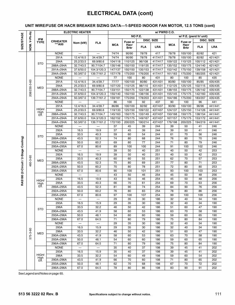
513 56 3222 02 Rev. B Specifications subject to change without notice. 111
See Legend and Notes on page 65.
UNIT WIRE/FUSE OR HACR BREAKER SIZING DATA—1-SPEED INDOOR FAN MOTOR, 12.5 TONS (cont)S
IZE
/ST
AG
E
NO
M. V
-Ph
-Hz
IFMTYPE
ELECTRIC HEATER w/ PWRD C.O.
CRHEATER***A00 Nom (kW) FLA
NO P.E. w/ P.E. (pwrd fr/ unit)
MCAFuse or
Hacr Brkr
DISC. SIZE
MCAFuse or
Hacr Brkr
DISC. SIZE
FLA LRA FLA LRA
RA
S18
0 (2
-Cir
cuit
/ 2-
Sta
ge
Co
olin
g)
208/
230-
3-60
STD
NONE — — 74/74 90/90 78/78 417 78/78 100/100 82/82 421291A 12.4/16.5 34.4/39.7 74/74 90/90 78/78 417/417 78/78 100/100 82/82 421/421294A 25.2/33.5 69.9/80.6 104/118 110/125 96/108 417/417 109/122 110/125 100/112 421/421
288A+294A 32.7/43.5 90.7/104.7 130/148 150/150 119/135 417/417 135/152 150/175 124/140 421/421291A+294A 37.6/50.0 104.3/120.3 147/137 150/150 135/153 417/417 152/142 175/150 139/158 421/421294A+294A 50.3/67.0 139.7/161.2 157/178 175/200 176/200 417/417 161/183 175/200 180/205 421/421
MED
NONE — — 77 100 80 431 80 100 85 435291A 12.4/16.5 34.4/39.7 77/77 100/100 80/80 431/431 80/80 100/100 85/85 435/435294A 25.2/33.5 69.9/80.6 107/120 110/125 98/110 431/431 112/125 125/125 102/115 435/435
288A+294A 32.7/43.5 90.7/104.7 133/151 150/175 122/138 431/431 138/155 150/175 126/142 435/435291A+294A 37.6/50.0 104.3/120.3 150/140 150/150 138/156 431/431 155/145 175/175 142/160 435/435294A+294A 50.3/67.0 139.7/161.2 159/181 175/200 178/203 431/431 164/186 175/200 183/207 435/435
HIGH/High Eff.
NONE — — 86 100 92 437 90 100 96 441291A 12.4/16.5 34.4/39.7 86/86 100/100 92/92 437/437 90/90 100/100 96/96 441/441294A 25.2/33.5 69.9/80.6 119/133 125/150 109/122 437/437 124/137 125/150 114/126 441/441
288A+294A 32.7/43.5 90.7/104.7 145/163 150/175 133/149 437/437 150/168 150/175 138/154 441/441291A+294A 37.6/50.0 104.3/120.3 162/152 175/175 149/167 437/437 167/157 175/175 153/172 441/441294A+294A 50.3/67.0 139.7/161.2 172/193 200/225 190/214 437/437 176/198 200/225 194/219 441/441
460-
3-60
STD
NONE — — 37 45 39 244 39 50 41 246292A 16.5 19.9 37 45 39 244 39 50 41 246295A 33.5 40.3 59 60 54 244 61 70 56 246
289A+295A 43.5 52.3 74 80 68 244 76 80 70 246292A+295A 50.0 60.2 69 80 77 244 71 80 79 246295A+295A 67.0 80.6 89 100 100 244 91 100 102 246
MED
NONE — — 39 50 40 251 40 50 42 253292A 16.5 19.9 39 50 40 251 40 50 42 253295A 33.5 40.3 60 60 55 251 62 70 57 253
289A+295A 43.5 52.3 75 80 69 251 77 80 71 253292A+295A 50.0 60.2 70 80 78 251 72 80 80 253295A+295A 67.0 80.6 90 100 101 251 93 100 103 253
HIGH/High Eff.
NONE — — 43 50 46 254 45 50 48 256292A 16.5 19.9 43 50 46 254 45 50 48 256295A 33.5 40.3 66 70 61 254 69 70 63 256
289A+295A 43.5 52.3 81 90 74 254 84 90 76 256292A+295A 50.0 60.2 76 80 83 254 78 80 86 256295A+295A 67.0 80.6 97 100 107 254 99 100 109 256
575-
3-60
STD
NONE — — 29 35 30 186 32 40 34 190293A 16.5 15.9 29 35 30 186 32 40 34 190296A 33.5 32.2 46 50 42 186 51 60 47 190
290A+296A 43.5 41.9 58 60 53 186 63 70 58 190293A+296A 50.0 48.1 54 60 60 186 59 60 65 190296A+296A 67.0 64.5 71 80 79 186 75 80 84 190
MED
NONE — — 29 35 30 186 32 40 34 190293A 16.5 15.9 29 35 30 186 32 40 34 190296A 33.5 32.2 46 50 42 186 51 60 47 190
290A+296A 43.5 41.9 58 60 53 186 63 70 58 190293A+296A 50.0 48.1 54 60 60 186 59 60 65 190296A+296A 67.0 64.5 71 80 79 186 75 80 84 190
HIGH/High Eff.
NONE — — 35 40 37 198 39 45 41 202293A 16.5 15.9 35 40 37 198 39 45 41 202296A 33.5 32.2 54 60 49 198 59 60 54 202
290A+296A 43.5 41.9 66 70 60 198 71 80 65 202293A+296A 50.0 48.1 62 70 68 198 67 70 72 202296A+296A 67.0 64.5 78 80 86 198 83 90 91 202
ELECTRICAL DATA (cont)

112 Specifications subject to change without notice. 513 56 3222 02 Rev. B
See Legend and Notes on page 65.
UNIT WIRE/FUSE OR HACR BREAKER SIZING DATA—2-SPEED BLOWER INDOOR FAN MOTOR, 6 TONS
SIZ
E/S
TA
GE
NO
M. V
-Ph
-Hz
IFMTYPE
ELECTRIC HEATER NO CONVENIENCE OUTLET (C.O). or UNPWR C.O.
CRHEATER***A00 Nom (kW) FLA
NO Power Exhaust (P.E.) w/ P.E. (pwrd fr/ unit)
MCAFuse or
Hacr Brkr
DISC. SIZE
MCAFuse or
Hacr Brkr
DISC. SIZE
FLA LRA FLA LRA
RA
S07
2 (1
-Cir
cuit
/ 1-
Sta
ge
Co
ol)
208/
230-
3-60
STD
NONE — — 34/33 50/50 32/32 167 35/35 50/50 35/34 169102A 4.9/6.5 13.6/15.6 34/33 50/50 32/32 167/167 35/35 50/50 35/34 169/169104B 7.9/10.5 21.9/25.3 37/41 50/50 33/37 167/167 39/43 50/50 36/39 169/169105A 12.0/16.0 33.4/38.5 51/57 60/60 47/52 167/167 53/59 60/60 49/54 169/169
104B+104B 15.8/21.0 43.8/50.5 64/72 70/80 59/66 167/167 66/74 70/80 61/68 169/169104B+105A 19.9/26.5 55.2/63.8 78/89 80/90 72/81 167/167 81/91 90/100 74/83 169/169
MED
NONE — — 35/34 50/50 34/33 193 37/36 50/50 36/35 195102A 4.9/6.5 13.6/15.6 35/34 50/50 34/33 193/193 37/36 50/50 36/35 195/195104B 7.9/10.5 21.9/25.3 39/42 50/50 35/38 193/193 41/44 50/50 37/40 195/195105A 12.0/16.0 33.4/38.5 53/58 60/60 48/53 193/193 55/61 60/70 50/55 195/195
104B+104B 15.8/21.0 43.8/50.5 66/73 70/80 60/67 193/193 68/76 70/80 62/69 195/195104B+105A 19.9/26.5 55.2/63.8 80/90 80/90 73/82 193/193 83/92 90/100 76/85 195/195
HIGH
NONE — — 37/36 50/50 37/36 217 39/38 50/50 39/38 219102A 4.9/6.5 13.6/15.6 37/36 50/50 37/36 217/217 39/38 50/50 39/38 219/219104B 7.9/10.5 21.9/25.3 41/44 50/50 38/40 217/217 44/47 50/50 40/43 219/219105A 12.0/16.0 33.4/38.5 56/61 60/70 51/56 217/217 58/63 60/70 53/58 219/219
104B+104B 15.8/21.0 43.8/50.5 69/76 70/80 63/69 217/217 71/78 80/80 65/72 219/219104B+105A 19.9/26.5 55.2/63.8 83/92 90/100 76/85 217/217 85/95 90/100 78/87 219/219
460-
3-60
STD
NONE — — 15 20 14 82 16 20 15 83106A 6.0 7.2 15 20 14 82 16 20 15 83108A 11.5 13.8 22 25 20 82 23 25 21 83109A 14.0 16.8 26 30 23 82 27 30 24 83
108A+108A 23.0 27.7 39 40 36 82 41 45 37 83108A+109A 25.5 30.7 43 45 39 82 44 45 40 83
MED
NONE — — 15 20 15 95 16 20 16 96106A 6.0 7.2 15 20 15 95 16 20 16 96108A 11.5 13.8 22 25 20 95 24 25 21 96109A 14.0 16.8 26 30 24 95 27 30 25 96
108A+108A 23.0 27.7 40 40 36 95 41 45 37 96108A+109A 25.5 30.7 44 45 40 95 45 45 41 96
HIGH
NONE — — 16 20 16 107 17 25 17 108106A 6.0 7.2 16 20 16 107 17 25 17 108108A 11.5 13.8 24 25 22 107 25 25 23 108109A 14.0 16.8 28 30 25 107 29 30 26 108
108A+108A 23.0 27.7 41 45 37 107 42 45 39 108108A+109A 25.5 30.7 45 45 41 107 46 50 42 108
575-
3-60 STD NONE — — 13 15 12 70 15 20 14 72
MED NONE — — 14 15 13 79 16 20 16 81
HIGH NONE — — 14 15 13 79 16 20 16 81
ELECTRICAL DATA (cont)

513 56 3222 02 Rev. B Specifications subject to change without notice. 113
See Legend and Notes on page 65.
UNIT WIRE/FUSE OR HACR BREAKER SIZING DATA—2-SPEED BLOWER INDOOR FAN MOTOR, 6 TONS (cont)S
IZE
/ST
AG
E
NO
M. V
-Ph
-Hz
IFMTYPE
ELECTRIC HEATER w/ PWRD C.O.
CRHEATER***A00 Nom (kW) FLA
NO P.E. w/ P.E. (pwrd fr/ unit)
MCAFuse or
Hacr Brkr
DISC. SIZE
MCAFuse or
Hacr Brkr
DISC. SIZE
FLA LRA FLA LRA
RA
S07
2 (1
-Cir
cuit
/ 1-
Sta
ge
Co
ol)
208/
230-
3-60
STD
NONE — — 38/38 50/50 38/38 172 40/40 50/50 40/40 174102A 4.9/6.5 13.6/15.6 38/38 50/50 38/38 172/172 40/40 50/50 40/40 174/174104B 7.9/10.5 21.9/25.3 43/47 50/50 39/42 172/172 45/49 50/50 41/45 174/174105A 12.0/16.0 33.4/38.5 57/63 60/70 52/58 172/172 59/65 60/70 54/60 174/174
104B+104B 15.8/21.0 43.8/50.5 70/78 70/80 64/71 172/172 72/80 80/90 66/74 174/174104B+105A 19.9/26.5 55.2/63.8 84/95 90/100 77/87 172/172 87/97 90/100 79/89 174/174
MED
NONE — — 40/39 50/50 40/39 198 42/41 60/60 42/41 200102A 4.9/6.5 13.6/15.6 40/39 50/50 40/39 198/198 42/41 60/60 42/41 200/200104B 7.9/10.5 21.9/25.3 45/48 50/50 41/44 198/198 47/50 60/60 43/46 200/200105A 12.0/16.0 33.4/38.5 59/64 60/70 54/59 198/198 61/67 70/70 56/61 200/200
104B+104B 15.8/21.0 43.8/50.5 72/79 80/80 66/73 198/198 74/82 80/90 68/75 200/200104B+105A 19.9/26.5 55.2/63.8 86/96 90/100 79/88 198/198 89/98 90/100 81/90 200/200
HIGH
NONE — — 42/41 60/60 42/41 222 44/43 60/60 44/43 224102A 4.9/6.5 13.6/15.6 42/41 60/60 42/41 222/222 44/43 60/60 44/43 224/224104B 7.9/10.5 21.9/25.3 47/50 60/60 43/46 222/222 50/53 60/60 45/48 224/224105A 12.0/16.0 33.4/38.5 62/67 70/70 56/61 222/222 64/69 70/70 59/63 224/224
104B+104B 15.8/21.0 43.8/50.5 75/82 80/90 68/75 222/222 77/84 80/90 70/77 224/224104B+105A 19.9/26.5 55.2/63.8 89/98 90/100 81/90 222/222 91/101 100/110 84/92 224/224
460-
3-60
STD
NONE — — 17 20 17 84 18 25 18 85106A 6.0 7.2 17 20 17 84 18 25 18 85108A 11.5 13.8 25 25 22 84 26 30 23 85109A 14.0 16.8 28 30 26 84 30 30 27 85
108A+108A 23.0 27.7 42 45 38 84 43 45 39 85108A+109A 25.5 30.7 46 50 42 84 47 50 43 85
MED
NONE — — 18 25 17 97 19 25 18 98106A 6.0 7.2 18 25 17 97 19 25 18 98108A 11.5 13.8 25 25 23 97 26 30 24 98109A 14.0 16.8 29 30 26 97 30 30 27 98
108A+108A 23.0 27.7 43 45 39 97 44 45 40 98108A+109A 25.5 30.7 46 50 42 97 48 50 43 98
HIGH
NONE — — 19 25 19 109 20 25 20 110106A 6.0 7.2 19 25 19 109 20 25 20 110108A 11.5 13.8 27 30 24 109 28 30 25 110109A 14.0 16.8 30 30 27 109 32 35 29 110
108A+108A 23.0 27.7 44 45 40 109 45 45 41 110108A+109A 25.5 30.7 48 50 43 109 49 50 45 110
575-
3-60 STD NONE — — 15 20 14 72 16 20 16 74
MED NONE — — 16 20 15 81 17 20 18 83
HIGH NONE — — 16 20 15 81 17 20 18 83
ELECTRICAL DATA (cont)

114 Specifications subject to change without notice. 513 56 3222 02 Rev. B
See Legend and Notes on page 65.
UNIT WIRE/FUSE OR HACR BREAKER SIZING DATA—2-SPEED INDOOR FAN MOTOR, 7.5 TONS
SIZ
E/S
TA
GE
NO
M. V
-Ph
-Hz
IFMTYPE
ELECTRIC HEATER NO CONVENIENCE OUTLET (C.O). or UNPWR C.O.
CRHEATER***A00 Nom (kW) FLA
NO Power Exhaust (P.E.) w/ P.E. (pwrd fr/ unit)
MCAFuse or
Hacr Brkr
DISC. SIZE
MCAFuse or
Hacr Brkr
DISC. SIZE
FLA LRA FLA LRA
RA
S09
0 (2
-Cir
cuit
/ 2-
Sta
ge
Co
olin
g)
208/
230-
3-60
STD
NONE — — 40/40 50/50 41/41 197 44/43 50/50 46/46 201117A 7.8/10.4 21.7/25.0 40/40 50/50 41/41 197/197 44/43 50/50 46/46 201/201110A 12.0/16.0 33.4/38.5 49/56 50/60 45/51 197/197 54/60 60/60 49/55 201/201111A 18.6/24.8 51.7/59.7 72/82 80/90 66/75 197/197 77/87 80/90 70/79 201/201112A 24.0/32.0 66.7/77.0 91/104 100/110 83/95 197/197 96/108 100/110 88/99 201/201
112A+117A 31.8/42.4 88.4/102.0 118/135 125/150 108/124 197/197 123/140 125/150 113/128 201/201
MED
NONE — — 43/42 50/50 45/44 227 46/46 50/50 49/48 231117A 7.8/10.4 21.7/25.0 43/42 50/50 45/44 227/227 46/46 50/50 49/48 231/231110A 12.0/16.0 33.4/38.5 53/58 60/60 48/53 227/227 58/63 60/70 53/58 231/231111A 18.6/24.8 51.7/59.7 76/85 80/90 69/78 227/227 81/90 90/90 74/82 231/231112A 24.0/32.0 66.7/77.0 95/106 100/110 87/98 227/227 99/111 100/125 91/102 231/231
112A+117A 31.8/42.4 88.4/102.0 122/138 125/150 112/126 227/227 126/142 150/150 116/131 231/231
HIGH
NONE — — 48/47 60/50 50/49 262 51/51 60/60 55/54 266117A 7.8/10.4 21.7/25.0 48/48 60/50 50/49 262/262 51/52 60/60 55/54 266/266110A 12.0/16.0 33.4/38.5 59/64 60/70 54/59 262/262 64/69 70/70 58/63 266/266111A 18.6/24.8 51.7/59.7 82/91 90/100 75/83 262/262 87/96 90/100 79/88 266/266112A 24.0/32.0 66.7/77.0 101/113 110/125 92/103 262/262 106/117 110/125 97/108 266/266
112A+117A 31.8/42.4 88.4/102.0 128/144 150/150 117/132 262/262 133/149 150/150 122/136 266/266
460-
3-60
STD
NONE — — 19 20 19 97 20 25 21 99116B 13.9 16.7 25 25 23 97 27 30 25 99113B 16.5 19.8 29 30 26 97 31 35 28 99114B 27.8 33.4 46 50 42 97 48 50 44 99115B 33.0 39.7 54 60 49 97 56 60 51 99128B 41.7 50.2 67 70 61 97 69 70 63 99
MED
NONE — — 20 25 20 113 21 25 22 115116B 13.9 16.7 26 30 24 113 28 30 26 115113B 16.5 19.8 30 30 27 113 32 35 29 115114B 27.8 33.4 47 50 43 113 49 50 45 115115B 33.0 39.7 55 60 50 113 57 60 52 115128B 41.7 50.2 68 70 62 113 70 70 64 115
HIGH
NONE — — 22 25 23 130 24 30 25 132116B 13.9 16.7 29 30 27 130 32 35 29 132113B 16.5 19.8 33 35 30 130 35 35 32 132114B 27.8 33.4 50 50 46 130 52 60 48 132115B 33.0 39.7 58 60 53 130 60 60 55 132128B 41.7 50.2 71 80 65 130 73 80 67 132
575-
3-60
STDNONE — — 14 15 14 79 18 20 19 83118A 18.0 17.3 26 30 23 79 30 30 27 83119A 36.0 34.6 47 50 43 79 52 60 47 83
MEDNONE — — 16 20 16 92 19 25 21 96118A 18.0 17.3 28 30 25 92 32 35 29 96119A 36.0 34.6 49 50 45 92 54 60 49 96
HIGHNONE — — 18 20 18 106 22 25 23 110118A 18.0 17.3 30 30 27 106 35 35 31 110119A 36.0 34.6 51 60 47 106 56 60 51 110
ELECTRICAL DATA (cont)

513 56 3222 02 Rev. B Specifications subject to change without notice. 115
See Legend and Notes on page 65.
UNIT WIRE/FUSE OR HACR BREAKER SIZING DATA—2-SPEED INDOOR FAN MOTOR, 7.5 TONS (cont)S
IZE
/ST
AG
E
NO
M. V
-Ph
-Hz
IFMTYPE
ELECTRIC HEATER w/ PWRD C.O.
CRHEATER***A00 Nom (kW) FLA
NO P.E. w/ P.E. (pwrd fr/ unit)
MCAFuse or
Hacr Brkr
DISC. SIZE
MCAFuse or
Hacr Brkr
DISC. SIZE
FLA LRA FLA LRA
RA
S09
0 (2
-Cir
cuit
/ 2-
Sta
ge
Co
olin
g)
208/
230-
3-60
STD
NONE — — 45/44 50/50 47/47 202 48/48 60/60 51/51 206117A 7.8/10.4 21.7/25.0 45/45 50/50 47/47 202/202 48/49 60/60 51/51 206/206110A 12.0/16.0 33.4/38.5 55/62 60/70 51/56 202/202 60/66 60/70 55/61 206/206111A 18.6/24.8 51.7/59.7 78/88 80/90 72/81 202/202 83/93 90/100 76/85 206/206112A 24.0/32.0 66.7/77.0 97/110 100/110 89/101 202/202 102/114 110/125 93/105 206/206
112A+117A 31.8/42.4 88.4/102.0 124/141 125/150 114/129 202/202 129/146 150/150 118/134 206/206
MED
NONE — — 47/47 60/50 50/49 232 51/50 60/60 55/54 236117A 7.8/10.4 21.7/25.0 47/47 60/50 50/49 232/232 51/52 60/60 55/54 236/236110A 12.0/16.0 33.4/38.5 59/64 60/70 54/59 232/232 64/69 70/70 58/63 236/236111A 18.6/24.8 51.7/59.7 82/91 90/100 75/83 232/232 87/96 90/100 79/88 236/236112A 24.0/32.0 66.7/77.0 101/112 110/125 92/103 232/232 105/117 110/125 96/107 236/236
112A+117A 31.8/42.4 88.4/102.0 128/144 150/150 117/132 232/232 132/148 150/150 121/136 236/236
HIGH
NONE — — 52/52 60/60 56/55 267 56/55 60/60 60/59 271117A 7.8/10.4 21.7/25.0 52/54 60/60 56/55 267/267 56/58 60/60 60/59 271/271110A 12.0/16.0 33.4/38.5 65/70 70/70 60/64 267/267 70/75 70/80 64/69 271/271111A 18.6/24.8 51.7/59.7 88/97 90/100 81/89 267/267 93/102 100/110 85/93 271/271112A 24.0/32.0 66.7/77.0 107/119 110/125 98/109 267/267 112/123 125/125 102/113 271/271
112A+117A 31.8/42.4 88.4/102.0 134/150 150/150 123/137 267/267 139/155 150/175 127/142 271/271
460-
3-60
STD
NONE — — 21 25 22 99 23 25 24 101116B 13.9 16.7 28 30 25 99 30 30 27 101113B 16.5 19.8 32 35 29 99 34 35 31 101114B 27.8 33.4 49 50 44 99 51 60 46 101115B 33.0 39.7 56 60 52 99 59 60 54 101128B 41.7 50.2 70 70 64 99 72 80 66 101
MED
NONE — — 22 25 23 115 24 25 25 117116B 13.9 16.7 29 30 26 115 31 35 28 117113B 16.5 19.8 33 35 30 115 35 35 32 117114B 27.8 33.4 50 50 45 115 52 60 47 117115B 33.0 39.7 58 60 53 115 60 60 55 117128B 41.7 50.2 71 80 65 115 73 80 67 117
HIGH
NONE — — 24 30 26 132 26 30 28 134116B 13.9 16.7 32 35 29 132 34 35 31 134113B 16.5 19.8 36 40 33 132 38 40 35 134114B 27.8 33.4 53 60 48 132 55 60 50 134115B 33.0 39.7 61 70 56 132 63 70 58 134128B 41.7 50.2 74 80 68 132 76 80 70 134
575-
3-60
STDNONE — — 16 20 16 81 19 25 21 85118A 18.0 17.3 28 30 25 81 32 35 29 85119A 36.0 34.6 49 50 45 81 54 60 49 85
MEDNONE — — 17 20 18 94 21 25 23 98118A 18.0 17.3 30 30 27 94 35 35 31 98119A 36.0 34.6 51 60 47 94 56 60 51 98
HIGHNONE — — 20 25 20 108 23 25 24 112118A 18.0 17.3 32 35 29 108 37 40 33 112119A 36.0 34.6 54 60 49 108 58 60 53 112
ELECTRICAL DATA (cont)

116 Specifications subject to change without notice. 513 56 3222 02 Rev. B
See Legend and Notes on page 65.
UNIT WIRE/FUSE OR HACR BREAKER SIZING DATA—2-SPEED INDOOR FAN MOTOR, 8.5 TONS
SIZ
E/S
TA
GE
NO
M. V
-Ph
-Hz
IFMTYPE
ELECTRIC HEATER NO CONVENIENCE OUTLET (C.O). or UNPWR C.O.
CRHEATER***A00 Nom (kW) FLA
NO Power Exhaust (P.E.) w/ P.E. (pwrd fr/ unit)
MCAFuse or
Hacr Brkr
DISC. SIZE
MCAFuse or
Hacr Brkr
DISC. SIZE
FLA LRA FLA LRA
RA
S10
2 (2
-Cir
cuit
/ 2-
Sta
ge
Co
olin
g)
208/
230-
3-60
STD
NONE — — 41/41 50/50 43/42 212 45/45 50/50 47/47 216117A 7.8/10.4 21.7/25.0 41/41 50/50 43/42 212/212 45/45 50/50 47/47 216/216110A 12.0/16.0 33.4/38.5 49/56 50/60 45/51 212/212 54/60 60/60 49/55 216/216111A 18.6/24.8 51.7/59.7 72/82 80/90 66/75 212/212 77/87 80/90 70/79 216/216112A 24.0/32.0 66.7/77.0 91/104 100/110 83/95 212/212 96/108 100/110 88/99 216/216
112A+117A 31.8/42.4 88.4/102.0 118/135 125/150 108/124 212/212 123/140 125/150 113/128 216/216
MED
NONE — — 42/42 50/50 44/44 216 46/46 60/50 48/48 220117A 7.8/10.4 21.7/25.0 42/42 50/50 44/44 216/216 46/46 60/50 48/48 220/220110A 12.0/16.0 33.4/38.5 51/57 60/60 47/52 216/216 56/62 60/70 51/56 220/220111A 18.6/24.8 51.7/59.7 74/84 80/90 68/76 216/216 79/88 80/90 72/81 220/220112A 24.0/32.0 66.7/77.0 93/105 100/110 85/96 216/216 97/110 100/110 89/101 220/220
112A+117A 31.8/42.4 88.4/102.0 120/136 125/150 110/125 216/216 125/141 125/150 114/129 220/220
HIGH
NONE — — 46/45 60/50 48/47 266 50/49 60/60 53/52 270117A 7.8/10.4 21.7/25.0 46/45 60/50 48/47 266/266 50/49 60/60 53/52 270/270110A 12.0/16.0 33.4/38.5 56/61 60/70 51/56 266/266 60/66 60/70 55/60 270/270111A 18.6/24.8 51.7/59.7 79/87 80/90 72/80 266/266 83/92 90/100 76/84 270/270112A 24.0/32.0 66.7/77.0 97/109 100/110 89/100 266/266 102/114 110/125 93/104 270/270
112A+117A 31.8/42.4 88.4/102.0 124/140 125/150 114/129 266/266 129/145 150/150 118/133 270/270
460-
3-60
STD
NONE — — 19 25 20 111 21 25 22 113116B 13.9 16.7 25 25 23 111 27 30 25 113113B 16.5 19.8 29 30 26 111 31 35 28 113114B 27.8 33.4 46 50 42 111 48 50 44 113115B 33.0 39.7 54 60 49 111 56 60 51 113128B 41.7 50.2 67 70 61 111 69 70 63 113
MED
NONE — — 20 25 20 114 21 25 22 116116B 13.9 16.7 26 30 23 114 28 30 25 116113B 16.5 19.8 29 30 27 114 32 35 29 116114B 27.8 33.4 46 50 42 114 49 50 44 116115B 33.0 39.7 54 60 50 114 57 60 52 116128B 41.7 50.2 67 70 62 114 70 70 64 116
HIGH
NONE — — 21 25 22 139 23 25 24 141116B 13.9 16.7 27 30 25 139 30 30 27 141113B 16.5 19.8 31 35 28 139 34 35 30 141114B 27.8 33.4 48 50 44 139 51 60 46 141115B 33.0 39.7 56 60 51 139 58 60 53 141128B 41.7 50.2 69 70 63 139 72 80 65 141
575-
3-60
STDNONE — — 17 20 17 87 21 25 21 91118A 18.0 17.3 26 30 23 87 30 30 27 91119A 36.0 34.6 47 50 43 87 52 60 47 91
MEDNONE — — 17 20 18 91 21 25 22 95118A 18.0 17.3 26 30 24 91 31 35 28 95119A 36.0 34.6 48 50 44 91 53 60 48 95
HIGHNONE — — 18 20 19 100 22 25 23 104118A 18.0 17.3 28 30 25 100 32 35 29 104119A 36.0 34.6 49 50 45 100 54 60 49 104
ELECTRICAL DATA (cont)

513 56 3222 02 Rev. B Specifications subject to change without notice. 117
See Legend and Notes on page 65.
UNIT WIRE/FUSE OR HACR BREAKER SIZING DATA—2-SPEED INDOOR FAN MOTOR, 8.5 TONS (cont)S
IZE
/ST
AG
E
NO
M. V
-Ph
-Hz
IFMTYPE
ELECTRIC HEATER w/ PWRD C.O.
CRHEATER***A00 Nom (kW) FLA
NO P.E. w/ P.E. (pwrd fr/ unit)
MCAFuse or
Hacr Brkr
DISC. SIZE
MCAFuse or
Hacr Brkr
DISC. SIZE
FLA LRA FLA LRA
RA
S10
2 (2
-Cir
cuit
/ 2-
Sta
ge
Co
olin
g)
208/
230-
3-60
STD
NONE — — 46/46 50/50 48/48 217 50/49 60/60 52/52 221117A 7.8/10.4 21.7/25.0 46/46 50/50 48/48 217/217 50/49 60/60 52/52 221/221110A 12.0/16.0 33.4/38.5 55/62 60/70 51/56 217/217 60/66 60/70 55/61 221/221111A 18.6/24.8 51.7/59.7 78/88 80/90 72/81 217/217 83/93 90/100 76/85 221/221112A 24.0/32.0 66.7/77.0 97/110 100/110 89/101 217/217 102/114 110/125 93/105 221/221
112A+117A 31.8/42.4 88.4/102.0 124/141 125/150 114/129 217/217 129/146 150/150 118/134 221/221
MED
NONE — — 47/47 60/60 50/49 221 51/51 60/60 54/54 225117A 7.8/10.4 21.7/25.0 47/47 60/60 50/49 221/221 51/51 60/60 54/54 225/225110A 12.0/16.0 33.4/38.5 57/63 60/70 52/58 221/221 62/68 70/70 56/62 225/225111A 18.6/24.8 51.7/59.7 80/90 80/90 73/82 221/221 85/94 90/100 78/86 225/225112A 24.0/32.0 66.7/77.0 99/111 100/125 90/102 221/221 103/116 110/125 95/106 225/225
112A+117A 31.8/42.4 88.4/102.0 126/142 150/150 115/131 221/221 131/147 150/150 120/135 225/225
HIGH
NONE — — 51/50 60/60 54/53 271 55/54 60/60 58/57 275117A 7.8/10.4 21.7/25.0 51/50 60/60 54/53 271/271 55/55 60/60 58/57 275/275110A 12.0/16.0 33.4/38.5 62/67 70/70 56/61 271/271 66/72 70/80 61/65 275/275111A 18.6/24.8 51.7/59.7 85/93 90/100 77/85 271/271 89/98 90/100 82/90 275/275112A 24.0/32.0 66.7/77.0 103/115 110/125 95/105 271/271 108/120 110/125 99/110 275/275
112A+117A 31.8/42.4 88.4/102.0 130/146 150/150 120/134 271/271 135/151 150/175 124/138 275/275
460-
3-60
STD
NONE — — 21 25 22 113 23 25 24 115116B 13.9 16.7 28 30 25 113 30 30 27 115113B 16.5 19.8 32 35 29 113 34 35 31 115114B 27.8 33.4 49 50 44 113 51 60 46 115115B 33.0 39.7 56 60 52 113 59 60 54 115128B 41.7 50.2 70 70 64 113 72 80 66 115
MED
NONE — — 22 25 23 116 24 25 25 118116B 13.9 16.7 28 30 26 116 31 35 28 118113B 16.5 19.8 32 35 29 116 34 35 31 118114B 27.8 33.4 49 50 45 116 51 60 47 118115B 33.0 39.7 57 60 52 116 59 60 54 118128B 41.7 50.2 70 70 64 116 72 80 66 118
HIGH
NONE — — 23 25 24 141 25 30 26 143116B 13.9 16.7 30 30 27 141 32 35 29 143113B 16.5 19.8 34 35 31 141 36 40 33 143114B 27.8 33.4 51 60 47 141 53 60 49 143115B 33.0 39.7 59 60 54 141 61 70 56 143128B 41.7 50.2 72 80 66 141 74 80 68 143
575-
3-60
STDNONE — — 18 20 19 89 22 25 23 93118A 18.0 17.3 28 30 25 89 32 35 29 93119A 36.0 34.6 49 50 45 89 54 60 49 93
MEDNONE — — 19 25 20 93 23 25 24 97118A 18.0 17.3 29 30 26 93 33 35 30 97119A 36.0 34.6 50 50 46 93 55 60 50 97
HIGHNONE — — 20 25 21 102 24 30 25 106118A 18.0 17.3 30 30 27 102 35 35 31 106119A 36.0 34.6 51 60 47 102 56 60 51 106
ELECTRICAL DATA (cont)

118 Specifications subject to change without notice. 513 56 3222 02 Rev. B
See Legend and Notes on page 65.
UNIT WIRE/FUSE OR HACR BREAKER SIZING DATA—2-SPEED INDOOR FAN MOTOR, 10 TONS
SIZ
E/S
TA
GE
NO
M. V
-Ph
-Hz
IFMTYPE
ELECTRIC HEATER NO CONVENIENCE OUTLET (C.O). or UNPWR C.O.
CRHEATER***A00 Nom (kW) FLA
NO Power Exhaust (P.E.) w/ P.E. (pwrd fr/ unit)
MCAFuse or
Hacr Brkr
DISC. SIZE
MCAFuse or
Hacr Brkr
DISC. SIZE
FLA LRA FLA LRA
RA
S12
0 (2
-Cir
cuit
/ 2-
Sta
ge
Co
olin
g)
208/
230-
3-60
STD
NONE — — 46/46 60/60 48/47 255 50/50 60/60 52/52 259117A 7.8/10.4 21.7/25.0 46/46 60/60 48/47 255/255 50/50 60/60 52/52 259/259110A 12.0/16.0 33.4/38.5 51/57 60/60 48/52 255/255 56/62 60/70 52/56 259/259112A 24.0/32.0 66.7/77.0 93/105 100/110 85/96 255/255 97/110 100/110 89/101 259/259
112A+117A 31.8/42.4 88.4/102.0 120/136 125/150 110/125 255/255 125/141 125/150 114/129 259/259112A+110A 37.6/50.0 104.2/120.3 140/129 150/150 128/146 255/255 144/134 150/150 132/151 259/259
MED
NONE — — 50/49 60/60 52/51 305 54/53 60/60 56/55 309117A 7.8/10.4 21.7/25.0 50/49 60/60 52/51 305/305 54/53 60/60 56/55 309/309110A 12.0/16.0 33.4/38.5 56/61 60/70 52/56 305/305 60/66 60/70 56/60 309/309112A 24.0/32.0 66.7/77.0 97/109 100/110 89/100 305/305 102/114 110/125 93/104 309/309
112A+117A 31.8/42.4 88.4/102.0 124/140 125/150 114/129 305/305 129/145 150/150 118/133 309/309112A+110A 37.6/50.0 104.2/120.3 144/133 150/150 132/150 305/305 149/138 150/150 137/154 309/309
HIGH
NONE — — 53/52 60/60 55/54 316 56/55 60/60 60/59 320117A 7.8/10.4 21.7/25.0 53/52 60/60 55/54 316/316 56/55 60/60 60/59 320/320110A 12.0/16.0 33.4/38.5 59/64 60/70 55/59 316/316 64/69 70/70 60/63 320/320112A 24.0/32.0 66.7/77.0 101/113 110/125 92/103 316/316 106/117 110/125 97/108 320/320
112A+117A 31.8/42.4 88.4/102.0 128/144 150/150 117/132 316/316 133/149 150/150 122/136 320/320112A+110A 37.6/50.0 104.2/120.3 148/137 150/150 135/153 316/316 152/141 175/175 140/157 320/320
460-
3-60
STD
NONE — — 23 30 23 122 25 30 26 124116B 13.9 16.7 26 30 23 122 28 30 26 124113B 16.5 19.8 29 30 27 122 32 35 29 124115B 33.0 39.7 54 60 50 122 57 60 52 124128B 41.7 50.2 67 70 62 122 70 70 64 124129B 50.0 60.1 65 70 73 122 67 70 75 124
MED
NONE — — 24 30 25 147 26 30 27 149116B 13.9 16.7 27 30 25 147 30 30 27 149113B 16.5 19.8 31 35 28 147 34 35 30 149115B 33.0 39.7 56 60 51 147 58 60 53 149128B 41.7 50.2 69 70 63 147 72 80 65 149129B 50.0 60.1 67 80 75 147 69 80 77 149
HIGH
NONE — — 26 30 27 152 28 30 29 154116B 13.9 16.7 29 30 27 152 32 35 29 154113B 16.5 19.8 33 35 30 152 35 35 32 154115B 33.0 39.7 58 60 53 152 60 60 55 154128B 41.7 50.2 71 80 65 152 73 80 67 154129B 50.0 60.1 69 80 76 152 71 80 79 154
575-
3-60
STD
NONE — — 18 20 19 95 22 25 23 99118A 18.0 17.3 26 30 24 95 31 35 28 99119A 36.0 34.6 48 50 44 95 53 60 48 99
118A+119A 54.0 52.0 57 60 64 95 62 70 68 99
MED
NONE — — 19 25 20 104 23 25 24 108118A 18.0 17.3 28 30 25 104 32 35 29 108119A 36.0 34.6 49 50 45 104 54 60 49 108
118A+119A 54.0 52.0 58 60 65 104 63 70 69 108
HIGH
NONE — — 21 25 22 118 25 30 26 122118A 18.0 17.3 30 30 27 118 35 35 31 122119A 36.0 34.6 51 60 47 118 56 60 51 122
118A+119A 54.0 52.0 60 70 67 118 65 70 71 122
ELECTRICAL DATA (cont)

513 56 3222 02 Rev. B Specifications subject to change without notice. 119
See Legend and Notes on page 65.
UNIT WIRE/FUSE OR HACR BREAKER SIZING DATA—2-SPEED INDOOR FAN MOTOR, 10 TONS (cont)S
IZE
/ST
AG
E
NO
M. V
-Ph
-Hz
IFMTYPE
ELECTRIC HEATER w/ PWRD C.O.
CRHEATER***A00 Nom (kW) FLA
NO P.E. w/ P.E. (pwrd fr/ unit)
MCAFuse or
Hacr Brkr
DISC. SIZE
MCAFuse or
Hacr Brkr
DISC. SIZE
FLA LRA FLA LRA
RA
S12
0 (2
-Cir
cuit
/ 2-
Sta
ge
Co
olin
g)
208/
230-
3-60
STD
NONE — — 51/51 60/60 53/53 260 55/54 60/60 58/57 264117A 7.8/10.4 21.7/25.0 51/51 60/60 53/53 260/260 55/54 60/60 58/57 264/264110A 12.0/16.0 33.4/38.5 57/63 60/70 53/58 260/260 62/68 70/70 58/62 264/264112A 24.0/32.0 66.7/77.0 99/111 100/125 90/102 260/260 103/116 110/125 95/106 264/264
112A+117A 31.8/42.4 88.4/102.0 126/142 150/150 115/131 260/260 131/147 150/150 120/135 264/264112A+110A 37.6/50.0 104.2/120.3 146/135 150/150 134/152 260/260 150/140 150/150 138/156 264/264
MED
NONE — — 55/54 60/60 58/56 310 58/57 70/70 62/61 314117A 7.8/10.4 21.7/25.0 55/54 60/60 58/56 310/310 58/57 70/70 62/61 314/314110A 12.0/16.0 33.4/38.5 62/67 70/70 58/61 310/310 66/72 70/80 62/65 314/314112A 24.0/32.0 66.7/77.0 103/115 110/125 95/105 310/310 108/120 110/125 99/110 314/314
112A+117A 31.8/42.4 88.4/102.0 130/146 150/150 120/134 310/310 135/151 150/175 124/138 314/314112A+110A 37.6/50.0 104.2/120.3 150/139 150/150 138/155 310/310 155/144 175/175 142/160 314/314
HIGH
NONE — — 57/56 70/60 61/60 321 61/60 70/70 65/64 325117A 7.8/10.4 21.7/25.0 57/56 70/60 61/60 321/321 61/60 70/70 65/64 325/325110A 12.0/16.0 33.4/38.5 65/70 70/70 61/64 321/321 70/75 70/80 65/69 325/325112A 24.0/32.0 66.7/77.0 107/119 110/125 98/109 321/321 112/123 125/125 102/113 325/325
112A+117A 31.8/42.4 88.4/102.0 134/150 150/150 123/137 321/321 139/155 150/175 127/142 325/325112A+110A 37.6/50.0 104.2/120.3 154/143 175/175 141/158 321/321 158/147 175/175 145/163 325/325
460-
3-60
STD
NONE — — 25 30 26 124 27 30 28 126116B 13.9 16.7 28 30 26 124 31 35 28 126113B 16.5 19.8 32 35 29 124 34 35 31 126115B 33.0 39.7 57 60 52 124 59 60 54 126128B 41.7 50.2 70 70 64 124 72 80 66 126129B 50.0 60.1 68 70 76 124 70 80 78 126
MED
NONE — — 26 30 28 149 28 30 30 151116B 13.9 16.7 30 30 28 149 32 35 30 151113B 16.5 19.8 34 35 31 149 36 40 33 151115B 33.0 39.7 59 60 54 149 61 70 56 151128B 41.7 50.2 72 80 66 149 74 80 68 151129B 50.0 60.1 69 80 77 149 72 80 79 151
HIGH
NONE — — 28 30 29 154 30 35 32 156116B 13.9 16.7 32 35 29 154 34 35 32 156113B 16.5 19.8 36 40 33 154 38 40 35 156115B 33.0 39.7 61 70 56 154 63 70 58 156128B 41.7 50.2 74 80 68 154 76 80 70 156129B 50.0 60.1 71 80 79 154 74 80 81 156
575-
3-60
STD
NONE — — 20 25 21 97 24 25 25 101118A 18.0 17.3 29 30 26 97 33 35 30 101119A 36.0 34.6 50 50 46 97 55 60 50 101
118A+119A 54.0 52.0 59 60 66 97 64 70 70 101
MED
NONE — — 21 25 22 106 25 30 26 110118A 18.0 17.3 30 30 27 106 35 35 31 110119A 36.0 34.6 51 60 47 106 56 60 51 110
118A+119A 54.0 52.0 60 70 67 106 65 70 71 110
HIGH
NONE — — 23 25 24 120 26 30 28 124118A 18.0 17.3 32 35 29 120 37 40 33 124119A 36.0 34.6 54 60 49 120 58 60 53 124
118A+119A 54.0 52.0 62 70 69 120 67 70 73 124
ELECTRICAL DATA (cont)

120 Specifications subject to change without notice. 513 56 3222 02 Rev. B
See Legend and Notes on page 65.
UNIT WIRE/FUSE OR HACR BREAKER SIZING DATA—2-SPEED INDOOR FAN MOTOR, 12.5 TONS
SIZ
E/S
TA
GE
NO
M. V
-Ph
-Hz
IFMTYPE
ELECTRIC HEATER NO CONVENIENCE OUTLET (C.O). or UNPWR C.O.
CRHEATER***A00 Nom (kW) FLA
NO Power Exhaust (P.E.) w/ P.E. (pwrd fr/ unit)
MCAFuse or
Hacr Brkr
DISC. SIZE
MCAFuse or
Hacr Brkr
DISC. SIZE
FLA LRA FLA LRA
RA
S15
0 (2
—C
ircu
it /
2—S
tag
e C
oo
ling
)
208/
230-
3-60
STD
NONE — — 63/62 80/80 65/64 370 67/66 80/80 70/69 374117A 7.8/10.4 21.7/25.0 63/62 80/80 65/64 370/370 67/66 80/80 70/69 374/374110A 12.0/16.0 33.4/38.5 63/62 80/80 65/64 370/370 67/66 80/80 70/69 374/374112A 24.0/32.0 66.7/77.0 95/106 100/110 87/98 370/370 99/111 100/125 91/102 374/374
112A+117A 31.8/42.4 88.4/102.0 122/138 125/150 112/126 370/370 126/142 150/150 116/131 374/374112A+110A 37.6/50.0 104.2/120.3 141/131 150/150 130/147 370/370 146/135 150/150 134/152 374/374
MED
NONE — — 65/64 80/80 68/67 394 69/68 80/80 72/71 398117A 7.8/10.4 21.7/25.0 65/64 80/80 68/67 394/394 69/68 80/80 72/71 398/398110A 12.0/16.0 33.4/38.5 65/64 80/80 68/67 394/394 69/68 80/80 72/71 398/398112A 24.0/32.0 66.7/77.0 97/109 100/110 89/100 394/394 102/114 110/125 93/104 398/398
112A+117A 31.8/42.4 88.4/102.0 124/140 125/150 114/129 394/394 129/145 150/150 118/133 398/398112A+110A 37.6/50.0 104.2/120.3 144/133 150/150 132/150 394/394 149/138 150/150 137/154 398/398
HIGH
NONE — — 68/67 80/80 71/70 405 72/71 80/80 75/74 409117A 7.8/10.4 21.7/25.0 68/67 80/80 71/70 405/405 72/71 80/80 75/74 409/409110A 12.0/16.0 33.4/38.5 68/67 80/80 71/70 405/405 72/71 80/80 75/74 409/409112A 24.0/32.0 66.7/77.0 101/113 110/125 92/103 405/405 106/117 110/125 97/108 409/409
112A+117A 31.8/42.4 88.4/102.0 128/144 150/150 117/132 405/405 133/149 150/150 122/136 409/409112A+110A 37.6/50.0 104.2/120.3 148/137 150/150 135/153 405/405 152/141 175/175 140/157 409/409
460-
3-60
STD
NONE — — 29 35 30 184 31 40 32 186116B 13.9 16.7 29 35 30 184 31 40 32 186113B 16.5 19.8 30 35 30 184 32 40 32 186115B 33.0 39.7 55 60 50 184 57 60 52 186128B 41.7 50.2 68 70 62 184 70 70 64 186129B 50.0 60.1 65 70 73 184 68 80 76 186
MED
NONE — — 30 40 31 196 32 40 33 198116B 13.9 16.7 30 40 31 196 32 40 33 198113B 16.5 19.8 31 40 31 196 34 40 33 198115B 33.0 39.7 56 60 51 196 58 60 53 198128B 41.7 50.2 69 70 63 196 72 80 65 198129B 50.0 60.1 67 80 75 196 69 80 77 198
HIGH
NONE — — 31 40 33 201 33 40 35 203116B 13.9 16.7 31 40 33 201 33 40 35 203113B 16.5 19.8 33 40 33 201 35 40 35 203115B 33.0 39.7 58 60 53 201 60 60 55 203128B 41.7 50.2 71 80 65 201 73 80 67 203129B 50.0 60.1 69 80 76 201 71 80 79 203
575-
3-60
STD
NONE — — 24 30 24 147 27 30 29 151118A 18.0 17.3 28 30 25 147 32 35 29 151119A 36.0 34.6 49 50 45 147 54 60 49 151
118A+119A 54.0 52.0 58 60 65 147 63 70 69 151
MED
NONE — — 24 30 24 147 27 30 29 151118A 18.0 17.3 28 30 25 147 32 35 29 151119A 36.0 34.6 49 50 45 147 54 60 49 151
118A+119A 54.0 52.0 58 60 65 147 63 70 69 151
HIGH
NONE — — 25 30 26 161 29 35 31 165118A 18.0 17.3 30 30 27 161 35 35 31 165119A 36.0 34.6 51 60 47 161 56 60 51 165
118A+119A 54.0 52.0 60 70 67 161 65 70 71 165
ELECTRICAL DATA (cont)

513 56 3222 02 Rev. B Specifications subject to change without notice. 121
See Legend and Notes on page 65.
UNIT WIRE/FUSE OR HACR BREAKER SIZING DATA—2-SPEED INDOOR FAN MOTOR, 12.5 TONS (cont)S
IZE
/ST
AG
E
NO
M. V
-Ph
-Hz
IFMTYPE
ELECTRIC HEATER w/ PWRD C.O.
CRHEATER***A00 Nom (kW) FLA
NO P.E. w/ P.E. (pwrd fr/ unit)
MCAFuse or
Hacr Brkr
DISC. SIZE
MCAFuse or
Hacr Brkr
DISC. SIZE
FLA LRA FLA LRA
RA
S15
0 (2
—C
ircu
it /
2—S
tag
e C
oo
ling
)
208/
230-
3-60
STD
NONE — — 68/67 80/80 71/70 375 71/71 80/80 75/74 379117A 7.8/10.4 21.7/25.0 68/67 80/80 71/70 375/375 71/71 80/80 75/74 379/379110A 12.0/16.0 33.4/38.5 68/67 80/80 71/70 375/375 71/71 80/80 75/74 379/379112A 24.0/32.0 66.7/77.0 101/112 110/125 92/103 375/375 105/117 110/125 96/107 379/379
112A+117A 31.8/42.4 88.4/102.0 128/144 150/150 117/132 375/375 132/148 150/150 121/136 379/379112A+110A 37.6/50.0 104.2/120.3 147/137 150/150 135/153 375/375 152/141 175/150 140/157 379/379
MED
NONE — — 70/69 80/80 73/72 399 74/73 80/80 78/77 403117A 7.8/10.4 21.7/25.0 70/69 80/80 73/72 399/399 74/73 80/80 78/77 403/403110A 12.0/16.0 33.4/38.5 70/69 80/80 73/72 399/399 74/73 80/80 78/77 403/403112A 24.0/32.0 66.7/77.0 103/115 110/125 95/105 399/399 108/120 110/125 99/110 403/403
112A+117A 31.8/42.4 88.4/102.0 130/146 150/150 120/134 399/399 135/151 150/175 124/138 403/403112A+110A 37.6/50.0 104.2/120.3 150/139 150/150 138/155 399/399 155/144 175/175 142/160 403/403
HIGH
NONE — — 73/72 80/80 77/76 410 76/76 90/90 81/80 414117A 7.8/10.4 21.7/25.0 73/72 80/80 77/76 410/410 76/76 90/90 81/80 414/414110A 12.0/16.0 33.4/38.5 73/72 80/80 77/76 410/410 76/76 90/90 81/80 414/414112A 24.0/32.0 66.7/77.0 107/119 110/125 98/109 410/410 112/123 125/125 102/113 414/414
112A+117A 31.8/42.4 88.4/102.0 134/150 150/150 123/137 410/410 139/155 150/175 127/142 414/414112A+110A 37.6/50.0 104.2/120.3 154/143 175/175 141/158 410/410 158/147 175/175 145/163 414/414
460-
3-60
STD
NONE — — 31 40 32 186 33 40 34 188116B 13.9 16.7 31 40 32 186 33 40 34 188113B 16.5 19.8 33 40 32 186 35 40 34 188115B 33.0 39.7 58 60 53 186 60 60 55 188128B 41.7 50.2 71 80 65 186 73 80 67 188129B 50.0 60.1 68 80 76 186 70 80 78 188
MED
NONE — — 32 40 33 198 34 40 35 200116B 13.9 16.7 32 40 33 198 34 40 35 200113B 16.5 19.8 34 40 33 198 36 40 35 200115B 33.0 39.7 59 60 54 198 61 70 56 200128B 41.7 50.2 72 80 66 198 74 80 68 200129B 50.0 60.1 69 80 77 198 72 80 79 200
HIGH
NONE — — 34 40 35 203 35 45 37 205116B 13.9 16.7 34 40 35 203 35 45 37 205113B 16.5 19.8 36 40 35 203 38 45 37 205115B 33.0 39.7 61 70 56 203 63 70 58 205128B 41.7 50.2 74 80 68 203 76 80 70 205129B 50.0 60.1 71 80 79 203 74 80 81 205
575-
3-60
STD
NONE — — 25 30 26 149 29 35 31 153118A 18.0 17.3 30 30 27 149 35 35 31 153119A 36.0 34.6 51 60 47 149 56 60 51 153
118A+119A 54.0 52.0 60 70 67 149 65 70 71 153
MED
NONE — — 25 30 26 149 29 35 31 153118A 18.0 17.3 30 30 27 149 35 35 31 153119A 36.0 34.6 51 60 47 149 56 60 51 153
118A+119A 54.0 52.0 60 70 67 149 65 70 71 153
HIGH
NONE — — 27 30 28 163 31 35 33 167118A 18.0 17.3 32 35 29 163 37 40 33 167119A 36.0 34.6 54 60 49 163 58 60 53 167
118A+119A 54.0 52.0 62 70 69 163 67 70 73 167
ELECTRICAL DATA (cont)

122 Specifications subject to change without notice. 513 56 3222 02 Rev. B
See Legend and Notes on page 65.
UNIT WIRE/FUSE OR HACR BREAKER SIZING DATA—2-SPEED INDOOR FAN MOTOR, 15 TONS
SIZ
E/S
TA
GE
NO
M. V
-Ph
-Hz
IFMTYPE
ELECTRIC HEATER NO CONVENIENCE OUTLET (C.O). or UNPWR C.O.
CRHEATER***A00 Nom (kW) FLA
NO Power Exhaust (P.E.) w/ P.E. (pwrd fr/ unit)
MCAFuse or
Hacr Brkr
DISC. SIZE
MCAFuse or
Hacr Brkr
DISC. SIZE
FLA LRA FLA LRA
RA
S18
0 (2
-Cir
cuit
/ 2-
Sta
ge
Co
olin
g)
208/
230-
3-60
STD
NONE — — 70/69 80/80 73/72 393 74/73 80/80 77/76 397291A 12.4/16.5 34.4/39.7 70/69 80/80 73/72 393/393 74/73 80/80 77/76 397/397294A 25.2/33.5 69.9/80.6 99/111 100/125 90/102 393/393 103/116 110/125 95/106 397/397
288A+294A 32.7/43.5 90.7/104.7 125/141 125/150 114/129 393/393 129/146 150/150 119/134 397/397291A+294A 37.6/50.0 104.3/120.3 142/131 150/150 130/147 393/393 146/135 150/150 134/152 397/397294A+294A 50.3/67.0 139.7/161.2 151/171 175/200 171/194 393/393 156/176 175/200 175/199 397/397
MED
NONE — — 72/71 80/80 75/74 417 76/75 100/90 79/78 421291A 12.4/16.5 34.4/39.7 72/71 80/80 75/74 417/417 76/75 100/90 79/78 421/421294A 25.2/33.5 69.9/80.6 101/113 110/125 93/104 417/417 106/118 110/125 97/108 421/421
288A+294A 32.7/43.5 90.7/104.7 127/144 150/150 117/132 417/417 132/148 150/150 121/136 421/421291A+294A 37.6/50.0 104.3/120.3 144/133 150/150 132/150 417/417 149/138 150/150 137/154 421/421294A+294A 50.3/67.0 139.7/161.2 154/174 175/200 173/197 417/417 158/179 175/200 177/201 421/421
HIGH
NONE — — 82 100 86 432 85 100 91 436291A 12.4/16.5 34.4/39.7 82/82 100/100 86/86 432/432 85/85 100/100 91/91 436/436294A 25.2/33.5 69.9/80.6 113/127 125/150 104/116 432/432 118/131 125/150 108/121 436/436
288A+294A 32.7/43.5 90.7/104.7 139/157 150/175 128/144 432/432 144/162 150/175 132/148 436/436291A+294A 37.6/50.0 104.3/120.3 156/146 175/175 143/162 432/432 161/151 175/175 148/166 436/436294A+294A 50.3/67.0 139.7/161.2 166/187 175/225 184/209 432/432 170/192 175/225 188/213 436/436
460-
3-60
STD
NONE — — 35 45 36 233 37 45 38 235292A 16.5 19.9 35 45 36 233 37 45 38 235295A 33.5 40.3 56 60 51 233 58 60 53 235
289A+295A 43.5 52.3 71 80 65 233 73 80 67 235292A+295A 50.0 60.2 65 70 74 233 68 80 76 235295A+295A 67.0 80.6 86 90 97 233 88 100 99 235
MED
NONE — — 36 45 37 245 38 50 39 247292A 16.5 19.9 36 45 37 245 38 50 39 247295A 33.5 40.3 57 60 52 245 59 60 54 247
289A+295A 43.5 52.3 72 80 66 245 74 80 68 247292A+295A 50.0 60.2 67 80 75 245 69 80 77 247295A+295A 67.0 80.6 87 100 98 245 89 100 100 247
HIGH
NONE — — 41 50 43 252 43 50 45 254292A 16.5 19.9 41 50 43 252 43 50 45 254295A 33.5 40.3 64 70 58 252 66 70 60 254
289A+295A 43.5 52.3 79 80 72 252 81 90 74 254292A+295A 50.0 60.2 73 80 81 252 76 80 83 254295A+295A 67.0 80.6 94 100 104 252 96 100 106 254
575-
3-60
STD
NONE — — 29 35 30 184 32 40 34 188293A 16.5 15.9 29 35 30 184 32 40 34 188296A 33.5 32.2 46 50 42 184 51 60 47 188
290A+296A 43.5 41.9 58 60 53 184 63 70 58 188293A+296A 50.0 48.1 54 60 60 184 59 60 65 188296A+296A 67.0 64.5 71 80 79 184 75 80 84 188
MED
NONE — — 29 35 30 184 32 40 34 188293A 16.5 15.9 29 35 30 184 32 40 34 188296A 33.5 32.2 46 50 42 184 51 60 47 188
290A+296A 43.5 41.9 58 60 53 184 63 70 58 188293A+296A 50.0 48.1 54 60 60 184 59 60 65 188296A+296A 67.0 64.5 71 80 79 184 75 80 84 188
HIGH
NONE — — 33 40 35 196 37 45 39 200293A 16.5 15.9 33 40 35 196 37 45 39 200296A 33.5 32.2 52 60 47 196 57 60 52 200
290A+296A 43.5 41.9 64 70 59 196 69 70 63 200293A+296A 50.0 48.1 60 70 66 196 65 70 70 200296A+296A 67.0 64.5 76 80 85 196 81 90 89 200
ELECTRICAL DATA (cont)

513 56 3222 02 Rev. B Specifications subject to change without notice. 123
See Legend and Notes on page 65.
UNIT WIRE/FUSE OR HACR BREAKER SIZING DATA—2-SPEED INDOOR FAN MOTOR, 15 TONS (cont) S
IZE
/ST
AG
E
NO
M. V
-Ph
-Hz
IFMTYPE
ELECTRIC HEATER w/ PWRD C.O.
CRHEATER***A00 Nom (kW) FLA
NO P.E. w/ P.E. (pwrd fr/ unit)
MCAFuse or
Hacr Brkr
DISC. SIZE
MCAFuse or
Hacr Brkr
DISC. SIZE
FLA LRA FLA LRA
RA
S18
0 (2
—C
ircu
it /
2—S
tag
e C
oo
ling
)
208/
230-
3-60
STD
NONE — — 75/74 90/80 78/77 398 78/78 100/100 82/82 402291A 12.4/16.5 34.4/39.7 75/74 90/80 78/77 398/398 78/78 100/100 82/82 402/402294A 25.2/33.5 69.9/80.6 105/117 110/125 96/107 398/398 109/122 110/125 100/112 402/402
288A+294A 32.7/43.5 90.7/104.7 131/147 150/150 120/135 398/398 135/152 150/175 124/139 402/402291A+294A 37.6/50.0 104.3/120.3 148/137 150/150 135/153 398/398 152/141 175/150 140/157 402/402294A+294A 50.3/67.0 139.7/161.2 157/177 175/200 176/200 398/398 162/182 175/200 180/204 402/402
MED
NONE — — 77/76 100/100 81/79 422 81/80 100/100 85/84 426291A 12.4/16.5 34.4/39.7 77/76 100/100 81/79 422/422 81/80 100/100 85/84 426/426294A 25.2/33.5 69.9/80.6 107/119 110/125 98/109 422/422 112/124 125/125 103/114 426/426
288A+294A 32.7/43.5 90.7/104.7 133/150 150/150 122/137 422/422 138/154 150/175 127/142 426/426291A+294A 37.6/50.0 104.3/120.3 150/139 150/150 138/155 422/422 155/144 175/175 142/160 426/426294A+294A 50.3/67.0 139.7/161.2 160/180 175/200 179/202 422/422 164/185 175/200 183/207 426/426
HIGH
NONE — — 86 100 92 437 90 100 96 441291A 12.4/16.5 34.4/39.7 86/86 100/100 92/92 437/437 90/90 100/100 96/96 441/441294A 25.2/33.5 69.9/80.6 119/133 125/150 109/122 437/437 124/137 125/150 114/126 441/441
288A+294A 32.7/43.5 90.7/104.7 145/163 150/175 133/149 437/437 150/168 150/175 138/154 441/441291A+294A 37.6/50.0 104.3/120.3 162/152 175/175 149/167 437/437 167/157 175/175 153/172 441/441294A+294A 50.3/67.0 139.7/161.2 172/193 200/225 190/214 437/437 176/198 200/225 194/219 441/441
460-
3-60
STD
NONE — — 37 45 38 235 39 50 40 237292A 16.5 19.9 37 45 38 235 39 50 40 237295A 33.5 40.3 58 60 53 235 61 70 55 237
289A+295A 43.5 52.3 73 80 67 235 76 80 69 237292A+295A 50.0 60.2 68 80 76 235 70 80 78 237295A+295A 67.0 80.6 89 100 100 235 91 100 102 237
MED
NONE — — 38 50 40 247 40 50 42 249292A 16.5 19.9 38 50 40 247 40 50 42 249295A 33.5 40.3 60 60 55 247 62 70 57 249
289A+295A 43.5 52.3 75 80 68 247 77 80 70 249292A+295A 50.0 60.2 70 80 77 247 72 80 79 249295A+295A 67.0 80.6 90 100 101 247 92 100 103 249
HIGH
NONE — — 43 50 46 254 45 50 48 256292A 16.5 19.9 43 50 46 254 45 50 48 256295A 33.5 40.3 66 70 61 254 69 70 63 256
289A+295A 43.5 52.3 81 90 74 254 84 90 76 256292A+295A 50.0 60.2 76 80 83 254 78 80 86 256295A+295A 67.0 80.6 97 100 107 254 99 100 109 256
575-
3-60
STD
NONE — — 30 35 32 186 34 40 36 190293A 16.5 15.9 30 35 32 186 34 40 36 190296A 33.5 32.2 48 50 44 186 53 60 49 190
290A+296A 43.5 41.9 61 70 55 186 65 70 60 190293A+296A 50.0 48.1 56 60 62 186 61 70 67 190296A+296A 67.0 64.5 73 80 81 186 77 80 86 190
MED
NONE — — 30 35 32 186 34 40 36 190293A 16.5 15.9 30 35 32 186 34 40 36 190296A 33.5 32.2 48 50 44 186 53 60 49 190
290A+296A 43.5 41.9 61 70 55 186 65 70 60 190293A+296A 50.0 48.1 56 60 62 186 61 70 67 190296A+296A 67.0 64.5 73 80 81 186 77 80 86 190
HIGH
NONE — — 35 40 37 198 39 45 41 202293A 16.5 15.9 35 40 37 198 39 45 41 202296A 33.5 32.2 54 60 49 198 59 60 54 202
290A+296A 43.5 41.9 66 70 60 198 71 80 65 202293A+296A 50.0 48.1 62 70 68 198 67 70 72 202296A+296A 67.0 64.5 78 80 86 198 83 90 91 202
ELECTRICAL DATA (cont)

124 Specifications subject to change without notice. 513 56 3222 02 Rev. B
Sequence of OperationGeneralThe sequence below describes the sequence of opera-tion for an electro-mechanical unit with and without a fac-tory-installed EconoMi$er® IV and X (called “economizer”in this sequence). For information regarding a direct digi-tal controller, see the start-up, operations, and trouble-shooting manual for the applicable controller.
Electro-mechanical units with no economizerCooling (single speed indoor fan motor) — When thethermostat calls for cooling, terminals G and Y1 areenergized. As a result, the indoor fan contactor (IFC) andthe compressor contactor (C1) are energized, causingthe indoor fan motor (IFM), compressor #1, and outdoorfan to start. If the unit has 2 stages of cooling, the thermo-stat will additionally energize Y2. The Y2 signal will ener-gize compressor contactor #2 (C2), causing compressor#2 to start. Regardless of the number of stages, the out-door fan motor runs continuously while unit is cooling.When the 2-speed indoor fan motor system is utilized theindoor fan motor runs at design CFM (full speed) duringthe heating operation.On 1-circuit/2-stage cooling model from 7.5 to 10 ton, 2-speed fan motor system is not available. Efficiencies tomeet the U.S. Department of Energy - 2018 IEER effi-ciency rating are achieved by using a precision 2-stagecompressor operation sequencing with one indoor fanmotor speed.
Cooling (2-speed indoor fan motor) — Per ASHRAE90.1-2016 standard, during the first stage of cooling oper-ation the 2-speed indoor fan motor system will adjust thefan motor to provide 66% of the total cfm established forthe unit. When a call for the second stage of cooling isrequired, the 2-speed fan motor system will allow the totalcfm for the unit established (100%). This is standard onall U.S. installed models with 2 circuit/2 stage cooling, tomeet U.S. Department of Energy - 2018 IEER efficiencyrating.The 2-speed indoor fan motor system automaticallyadjusts the indoor fan motor speed in sequence with theunits cooling operation. Per ASHRAE 90.1-2016 stan-dard, during the first stage of cooling operation, the2-speed controller will adjust the fan motor to provide66% of the total cfm established for the unit. When a callfor the second stage of cooling is required, the 2-speedfan motor controller will allow the total cfm for the unitestablished (100%). During the heating mode, the2-speed fan controller will allow total design cfm (100%)operation and during the ventilation mode, will allow oper-ation to 66% of total cfm.Heating (Single or 2-speed indoor fan motor) NOTE: RAS units are sold as cooling only. If electricheaters are required; use only factory-approved electricheaters. They will operated as described below.Units have either 1 or 2 stages of electric heat. When thethermostat calls for heating, power is applied to the W1terminal at the unit. The unit control will energize theindoor fan contactor and the first stage of electric heat.
On units with 2-stage heating, when additional heating isrequired, the second stage of electric heat (if equipped)will be energized when power is applied at the W2 termi-nal on the unit.
Electro-mechanical units with an economizerCooling — When free cooling is not available, the com-pressors will be controlled by the zone thermostat. Whenfree cooling is available, the outdoor-air damper is modu-lated by the EconoMi$er® IV and X control to provide a 50°F(10°C) to 55°F (13°C) mixed-air temperature into the zone.As the mixed air temperature fluctuates above 55°F (13°C)or below 50°F (10°C) dampers will be modulated (open orclose) to bring the mixed-air temperature back within con-trol. If mechanical cooling is utilized with free cooling, theoutdoor-air damper will maintain its current position at thetime the compressor is started. If the increase in coolingcapacity causes the mixed-air temperature to drop below45°F (7°C), then the outdoor-air damper position will bedecreased to the minimum position. If the mixed-air tem-perature continues to fall, the outdoor-air damper will close.Control returns to normal once the mixed-air temperaturerises above 48°F (9°C). The power exhaust fans will beenergized and de-energized, if installed, as the outdoor-airdamper opens and closes. If field-installed accessory CO2 sensors are connected tothe EconoMi$er IV and X control, a demand controlledventilation strategy will begin to operate. As the CO2 levelin the zone increases above the CO2 setpoint, the mini-mum position of the damper will be increased proportion-ally. As the CO2 level decreases because of the increasein fresh air, the outdoor-air damper will be proportionallyclosed. For EconoMi$er IV and X operation, there mustbe a thermostat call for the fan (G). If the unit is occupiedand the fan is on, the damper will operate at minimumposition. Otherwise, the damper will be closed.When the EconoMi$er IV and X control is in the occupiedmode and a call for cooling exists (Y1 on the thermostat),the control will first check for indoor fan operation. If thefan is not on, then cooling will not be activated. If the fanis on, then the control will open the EconoMi$er IV and Xdamper to the minimum position.On the initial power to the EconoMi$er IV and X control, itwill take the damper up to 2 1/2 minutes before it begins toposition itself. After the initial power-up, further changesin damper position can take up to 30 seconds to initiate.Damper movement from full closed to full open (or viceversa) will take between 1 1/2 and 2 1/2 minutes. If freecooling can be used as determined from the appropriatechangeover command (switch, dry bulb, enthalpy curve,differential dry bulb, or differential enthalpy), then thecontrol will modulate the dampers open to maintain themixed air temperature setpoint at 50°F (10°C) to 55°F(13°C). If there is a further demand for cooling (coolingsecond stage - Y2 is energized), then the control willbring on compressor stage 1 to maintain the mixed airtemperature setpoint. The EconoMi$er IV and X damperwill be open at maximum position.2-Speed NOTE: When operating in ventilation mode only,the indoor fan motor will automatically adjust to 66% ofthe total cfm established.
CONTROLS
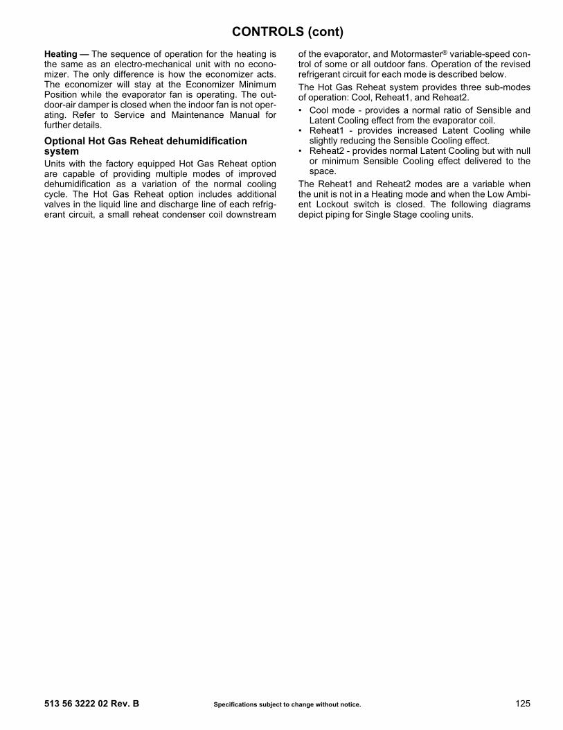
513 56 3222 02 Rev. B Specifications subject to change without notice. 125
Heating — The sequence of operation for the heating isthe same as an electro-mechanical unit with no econo-mizer. The only difference is how the economizer acts.The economizer will stay at the Economizer MinimumPosition while the evaporator fan is operating. The out-door-air damper is closed when the indoor fan is not oper-ating. Refer to Service and Maintenance Manual forfurther details.
Optional Hot Gas Reheat dehumidification system Units with the factory equipped Hot Gas Reheat optionare capable of providing multiple modes of improveddehumidification as a variation of the normal coolingcycle. The Hot Gas Reheat option includes additionalvalves in the liquid line and discharge line of each refrig-erant circuit, a small reheat condenser coil downstream
of the evaporator, and Motormaster® variable-speed con-trol of some or all outdoor fans. Operation of the revisedrefrigerant circuit for each mode is described below. The Hot Gas Reheat system provides three sub-modesof operation: Cool, Reheat1, and Reheat2. • Cool mode - provides a normal ratio of Sensible and
Latent Cooling effect from the evaporator coil. • Reheat1 - provides increased Latent Cooling while
slightly reducing the Sensible Cooling effect. • Reheat2 - provides normal Latent Cooling but with null
or minimum Sensible Cooling effect delivered to thespace.
The Reheat1 and Reheat2 modes are a variable whenthe unit is not in a Heating mode and when the Low Ambi-ent Lockout switch is closed. The following diagramsdepict piping for Single Stage cooling units.
CONTROLS (cont)

126 Specifications subject to change without notice. 513 56 3222 02 Rev. B
NORMAL COOLING MODE — HOT GAS RE-HEAT SYSTEM
SUBCOOLING MODE (REHEAT 1) — HOT GAS RE-HEAT SYSTEM
SUBCOOLING MODE (REHEAT 2) — HOT GAS RE-HEAT SYSTEM
CONDENSER COILH
EVAPORATOR COIL
COMPRESSOR
OUTDOOR AIR
INDOOR LEAVING AIR
INDOOR ENTERING AIR
DSVxVALVE
CSVxVALVE
ACCUTROLMETERING
DEVICE
REHEAT MODEMETERING
DEVICE (TXV)
= CLOSED VALVE
= OPEN VALVE
CONDENSER COILH
EVAPORATOR COIL
COMPRESSOR
OUTDOOR AIR
INDOOR LEAVING AIR
INDOOR ENTERING AIR
DSVxVALVE
CSVxVALVE
ACCUTROLMETERING
DEVICE
REHEAT MODEMETERING
DEVICE (TXV)
= CLOSED VALVE= OPEN VALVE
H
COMPRESSOR
OUTDOOR AIR
INDOOR LEAVING AIR
INDOOR ENTERING AIR
DSVxVALVE
CSVxVALVE
ACCUTROLMETERING
DEVICE
REHEAT MODEMETERING
DEVICE (TXV)
= CLOSED VALVE= OPEN VALVE
EVAPORATOR COIL
CONDENSER COIL
CONTROLS (cont)

513 56 3222 02 Rev. B Specifications subject to change without notice. 127
Note about this specification: These specifications are written in“Masterformat” as published by the Construction Specification Institute.Please feel free to copy this specification directly into your buildingspec.
Cooling only/electric heat packaged rooftopHVAC guide specificationsSize range: 6 to 15 Nominal TonsModel Number: RAS072-180Part 1 — (23 06 80) Schedules for decentralized HVAC equipment1.01 (23 06 80.13) Decentralized Unitary HVAC Equip-
ment ScheduleA. (23 06 80.13.A.) Rooftop unit (RTU) schedule
1. Schedule is per the project specificationrequirements.
Part 2 — (23 07 16) HVAC equipment installation2.01 (23 07 16.13) Decentralized rooftop units:
A. (23 07 16.13.A.) Evaporator fan compartment:1. Interior cabinet surfaces shall be insulated
with a minimum 1/2-in. thick, minimum 1 1/2-lbdensity, flexible fiberglass insulation bondedwith a phenolic binder, neoprene coated onthe air side.
2. Insulation and adhesive shall meet NFPA 90Arequirements for flame spread and smokegeneration.
3. Unit internal insulation linings shall be resis-tant to mold growth in accordance with “moldgrowth and humidity” test in ASTM C1338,G21, and UL 181 or comparable test method.Air stream surfaces shall be evaluated inaccordance with the “Erosion Test” in UL 181,as part of ASTM C1071.
B. (23 07 16.13.B.) Electric heat compartment:1. Aluminum foil-faced fiberglass insulation shall
be used.2. Insulation and adhesive shall meet NFPA 90A
requirements for flame spread and smokegeneration.
Part 3 — (23 07 13) Instrumentation and control devices for HVAC3.01 (23 07 13.23) Sensors and transmitters
A. (23 07 13.23.A.) Thermostats1. Thermostats must:
a. energize both "W" and "G" when calling forheat.
b. have capability to energize 2 differentstages of cooling, and 2 different stages ofheating.
c. include capability for occupancy scheduling.Part 4 — (23 09 33) Electric and electronic control system for HVAC4.01 (23 09 33.13) Decentralized, rooftop units
A. (23 09 33.13.A.) General:
1. Shall be complete with self-contained low-volt-age control circuit protected by a resettablecircuit breaker on the 24-v transformer side.Transformer shall have 75VA capability.
2. Shall utilize color-coded wiring.3. Shall include a central control terminal board
to conveniently and safely provide connectionpoints for vital control functions such as:smoke detectors, phase monitor, economizer,thermostat, DDC control options, and low andhigh pressure switches.
4. Unit shall include a minimum of one 8-pinscrew terminal connection board for connec-tion of control wiring.
B. (23 09 33.13.B.) Safeties:1. Compressor over-temperature, over-current.
High internal pressure differential.2. Low-pressure switch.
a. Units shall have different sized connectorsfor the circuit 1 and circuit 2 low and highpressure switches. They shall physicallyprevent the cross-wiring of the safetyswitches between circuits 1 and 2.
b. Low-pressure switch shall use differentcolor wire than the high-pressure switch.The purpose is to assist the installer andservice technician to correctly wire and ortroubleshoot the rooftop unit.
3. High-pressure switch.a. Units shall have different sized connectors
for the circuit 1 and circuit 2 low and high-pressure switches. They shall physicallyprevent the cross-wiring of the safetyswitches between circuits 1 and 2.
b. High-pressure switch shall use differentcolor wire than the low-pressure switch.The purpose is to assist the installer andservice technician to correctly wire and ortroubleshoot the rooftop unit.
4. Automatic reset, motor thermal overload protector.
Part 5 — (23 09 93) Sequence of operations for HVAC controls5.01 (23 09 93.13) Decentralized, Rooftop Units:
A. (23 09 93.13.A.) INSERT SEQUENCE OF OPERATION
Part 6 — (23 40 13) Panel air filters6.01 (23 40 13 13) Decentralized rooftop units:
A. (23 40 13 13.A.) Standard filter section1. Shall consist of factory-installed, low velocity,
disposable 2-in. thick fiberglass filters of com-mercially available sizes.
2. Unit shall use only one filter size. Multiplesizes are not acceptable.
3. Filters shall be accessible through a dedi-cated, weather tight access panel with ‘no-tool’
GUIDE SPECIFICATIONS

128 Specifications subject to change without notice. 513 56 3222 02 Rev. B
removal as described in the unit cabinet sec-tion of this specification (23 81 19 13.G.).
Part 7 — (23 81 19) Self-contained air conditioners7.01 (23 81 19.13) Small-Capacity Self-Contained Air
Conditioners (RAS072-180)A. (23 81 19.13.A.) General
1. Outdoor, rooftop mounted, electrically con-trolled, heating and cooling unit utilizing a fullyhermetic scroll compressor(s) for cooling andheating duty.
2. Factory assembled, single-piece heating andcooling rooftop unit. Contained within the unitenclosure shall be all factory wiring, piping,controls, and special features required prior tofield start-up.
3. Unit shall use R-410A refrigerant.4. Unit shall be installed in accordance with the
manufacturer’s instructions.5. Unit must be selected and installed in compli-
ance with local, state, and federal codes.B. (23 81 19.13.B.) Quality Assurance
1. Unit meets Department of Energy 2018,ASHRAE 90.1-2016 and IECC1-2015 stan-dards.
2. Unit shall be rated in accordance with AHRIStandards 340/360.
3. Unit shall be designed to conform to ASHRAE15.
4. Unit shall be UL-tested and certified in accor-dance with ANSI Z21.47 Standards andUL-listed and certified under Canadian stan-dards as a total package for safety require-ments.
5. Insulation and adhesive shall meet NFPA 90Arequirements for flame spread and smokegeneration.
6. Unit casing shall be capable of withstanding500-hour salt spray exposure per ASTM B117(scribed specimen).
7. Roof curb shall be designed to conform toNRCA Standards.
8. Unit shall be subjected to a completely auto-mated run test on the assembly line. The datafor each unit will be stored at the factory, andmust be available upon request.
9. Unit shall be designed in accordance with ULStandard 1995, ETL listed including tested towithstand rain.
10. Unit shall be constructed to prevent intrusionof snow and tested to prevent snow intrusioninto the control box up to 40 mph.
11. Unit shake tested to assurance level 1, ASTMD4169 to ensure shipping reliability.
12. High Efficiency Motors listed shall meet sec-tion 313 of the Energy Independence andSecurity Act of 2007 (EISA 2007).
C. (23 81 19.13.C.) Delivery, storage, and handling1. Unit shall be stored and handled per manufac-
turer’s recommendations.2. Lifted by crane requires either shipping top
panel or spreader bars.3. Unit shall only be stored or positioned in the
upright position. D. (23 81 19.13.D.) Project conditions:
1. As specified in the contract.E. (23 81 19.13.E.) Operating characteristics
1. Unit shall be capable of starting and running at115°F (46°C) ambient outdoor temperature,meeting maximum load criteria of AHRI Stan-dard 340/360 at ± 10% voltage.
2. Compressor with standard controls shall becapable of operation down to 40°F (4°C),ambient outdoor temperatures. Accessorywinter start kit is necessary if mechanicallycooling at ambient temperatures below 25°F(–4°C).
3. Unit shall be field convertible from factory fur-nished vertical to horizontal airflow on all mod-els. No special kit required on 072-150models. Supply duct kit required for 180 sizemodel only.
4. Unit shall be capable of field mixed operation:vertical supply with horizontal return or hori-zontal supply with vertical return.
F. (23 81 19.13.F.) Electrical Requirements1. Main power supply voltage, phase, and fre-
quency must match those required by themanufacturer.
G. (23 81 19.13.G.) Unit cabinet1. Unit cabinet shall be constructed of galvanized
steel, and shall be bonderized and coated witha pre-painted baked enamel finish on all exter-nally exposed surfaces.
2. Unit cabinet exterior paint shall be: film thick-ness, (dry) 0.003 inches minimum, gloss (perASTM D523, 60°F/16°C): 60, Hardness: H to2H Pencil hardness.
3. Evaporator fan compartment interior cabinetinsulation shall conform to AHRI Standards340/360 minimum exterior sweat criteria. Inte-rior surfaces shall be insulated with a mini-mum 1/2-in. thick, 1-lb density, flexiblefiberglass insulation, neoprene coated on theair side. Aluminum foil-faced fiberglass insula-tion shall be used in the heat compartment.
4. Base of unit shall have a minimum of fourlocations for thru-the-base electrical connec-tions standard.
1 IECC is a registered trademark of International Code Council, Inc.
GUIDE SPECIFICATIONS (cont)

513 56 3222 02 Rev. B Specifications subject to change without notice. 129
5. Base rail:a. Unit shall have base rails on a minimum of
2 sides.b. Holes shall be provided in the base rails for
rigging shackles to facilitate maneuveringand overhead rigging.
c. Holes shall be provided in the base rail formoving the rooftop by fork truck.
d. Base rail shall be a minimum of 16-gaugethickness.
6. Condensate pan and connections:a. Shall be a sloped condensate drain pan
made of a non-corrosive material.b. Shall comply with ASHRAE Standard 62.c. Shall use a 3/4-in. to 14 NPT drain connec-
tion, through the side of the drain pan. Con-nection shall be made per manufacturer’srecommendations.
7. Top panel:a. Shall be a single piece top panel on 072
thru 120 sizes, two piece on 150 and 180sizes.
8. Electrical connections:a. All unit power wiring shall enter unit cabinet
at a single, factory-prepared, knockoutlocation.
b. Thru-the-base capability.1) Thru-the-base provisions / connections
are available as standard with everyunit. When bottom connections arerequired, field furnished couplings arerequired.
2) Optional, factory approved, water-tightconnection method must be used forthru-the-base electrical connections.
3) No basepan penetration, other thanthose authorized by the manufacturer,is permitted.
9. Component access panels (standard):a. Cabinet panels shall be easily removable
for servicing.b. Unit shall have one factory-installed,
removable, tool-less filter access panel.c. Panels covering control box and filter shall
have molded composite handles while theblower access door shall have an inte-grated flange for easy removal.
d. Handles shall be UV modified, composite.They shall be permanently attached, andrecessed into the panel.
e. Screws on the vertical portion of all remov-able access panel shall engage into heatresistant, molded composite collars.
f. Collars shall be removable and easilyreplaceable using manufacturer recom-mended parts.
H. (23 81 19.13.H.) Coils1. Standard aluminum fin/copper tube coils:
a. Standard evaporator and condenser coilsshall have aluminum lanced plate finsmechanically bonded to seamless internallygrooved copper tubes with all joints brazed.
b. Evaporator coils shall be leak tested to 150psig, pressure tested to 450 psig, and qual-ified to UL 1995 burst test at 1775 psig.
c. Condenser coils shall be leak tested to 150psig, pressure tested to 650 psig, and qual-ified to UL 1995 burst test at 1980 psig.
2. Optional pre-coated aluminum-fin condensercoils:a. Shall have a durable epoxy-phenolic coat-
ing to provide protection in mildly corrosivecoastal environments.
b. Coating shall be applied to the aluminum finstock prior to the fin stamping process tocreate an inert barrier between the alumi-num fin and copper tube.
c. Epoxy-phenolic barrier shall minimize gal-vanic action between dissimilar metals.
3. Optional copper-fin evaporator and con-denser coils:a. Shall be constructed of copper fins
mechanically bonded to copper tubes andcopper tube sheets.
b. Galvanized steel tube sheets shall not beacceptable.
c. A polymer strip shall prevent coil assemblyfrom contacting the sheet metal coil pan tominimize potential for galvanic corrosionbetween coil and pan.
4. Optional E-coated aluminum-fin, evaporatorand condenser coils:a. Shall have a flexible epoxy polymer coating
uniformly applied to all coil surface areaswithout material bridging between fins.
b. Coating process shall ensure complete coilencapsulation of tubes, fins, and headers.
c. Color shall be high gloss black with glossper ASTM D523-89.
d. Uniform dry film thickness from 0.8 to 1.2mil on all surface areas including fin edges.
e. Superior harness characteristics of 2H perASTM D3363-92A and cross-hatch adhe-sion of 4B-5B per ASTM D3359-93.
f. Impact resistance shall be up to 160 in.-lb(ASTM D2794-93).
g. Humidity and water immersion shall be upto minimum 1000 and 250 hours respec-tively (ASTM D2247-92 and ASTM D870-92).
GUIDE SPECIFICATIONS (cont)
130 Specifications subject to change without notice. 513 56 3222 02 Rev. B
h. Corrosion durability shall be confirmedthrough testing to be no less than 6000hours salt spray per ASTM B117-90.
I. (23 81 19.13.I.) Refrigerant components1. Refrigerant circuit shall include the following
control, safety, and maintenance features:a. Dual circuit — two stage cooling models
(090, 102, 120, 150, 180) shall use fixedorifice metering system shall prevent mal-distribution of two-phase refrigerant byincluding multiple fixed orifice devices ineach refrigeration circuit. Each orifice is tobe optimized to the coil circuit it serves.
b. Single circuit — two stage cooling models089, 100, and 119 shall use one fixed ori-fice and one TXV metering device to assistin optimum latent heat removal from a sin-gle circuit design. Model 072 units use onefixed metering device.
c. Refrigerant filter drier - Solid core design.d. Service gauge connections on suction and
discharge lines.2. Pressure gauge access through a specially
designed access port in the top panel of theunit.
3. There shall be gauge line access port in theskin of the rooftop, covered by a black, remov-able plug.a. The plug shall be easy to remove and
replace.b. When the plug is removed, the gauge
access port shall enable maintenance per-sonnel to route their pressure gauge lines.
c. This gauge access port shall facilitate cor-rect and accurate condenser pressurereadings by enabling the reading with thecompressor access panel on.
d. The plug shall be made of a leak proof,UV-resistant, composite material.
4. Compressors:a. Unit shall use fully hermetic, scroll com-
pressor for each independent refrigerationcircuit.
b. Models 090, 102, 120, 150, 180 with dualrefrigerant circuit shall contain two scrollcompressors (one per circuit), models 089,100 and 119 with single circuit and twostage cooling shall contain one dual stagecompressor. Model 072 shall contain onestage scroll compressor.
c. Compressor motors shall be cooled byrefrigerant gas passing through motor wind-ings.
d. Compressors shall be internally protectedfrom high discharge temperature condi-tions.
e. Compressors shall be protected from anover-temperature and over-amperage con-ditions by an internal, motor overloaddevice.
f. Compressor shall be factory-mounted onrubber grommets.
g. Compressor motors shall have internal linebreak thermal, current overload and highpressure differential protection.
h. Crankcase heaters shall not be required fornormal operating range, unless required bythe manufacturer due to refrigerant chargelimits.
J. (23 81 19.13.J.) Filter section1. Filters access is specified in the unit cabinet
section of this specification.2. Filters shall be held in place by a preformed,
slide-out filter tray, facilitating easy removaland installation.
3. Shall consist of factory-installed, low velocity,throw-away 2-in. thick fiberglass filters.
4. Filters shall be standard, commercially avail-able sizes.
5. Only one size filter per unit is allowed.K. (23 81 19.13.K.) Evaporator fan and motor
1. Evaporator fan motor:a. Shall have permanently lubricated bear-
ings.b. Shall have inherent automatic-reset ther-
mal overload protection or circuit breaker.c. Shall have a maximum continuous bhp rat-
ing for continuous duty operation; no safetyfactors above that rating shall be required.
2. Belt-driven evaporator fan:a. Belt drive shall include an adjustable-pitch
motor pulley.b. Shall use sealed, permanently lubricated
ball-bearing type.c. Blower fan shall be double-inlet type with
forward-curved blades.d. Shall be constructed from steel with a finish
that aids with corrosion resistance and thatis dynamically balanced.
L. (23 81 19.13.L.) Condenser and fan motors1. Condenser fan motors:
a. Shall be a totally enclosed motor.b. Shall use permanently lubricated bearings.c. Shall have inherent thermal overload pro-
tection with an automatic reset feature.d. Shall use a shaft-down design on 072 to
120 and 180 models and shaft-up on 150size with rain shield.
2. Condenser fans:a. Shall be a direct-driven propeller type fan.
GUIDE SPECIFICATIONS (cont)

513 56 3222 02 Rev. B Specifications subject to change without notice. 131
b. Shall have galvalum blades riveted to steelspiders that have corrosion-resistant prop-erties and shall be dynamically balanced.
M. (23 81 19.13.M.) Special features options andaccessories
1. 2-speed indoor fan motor system shall bestandard on all models with dual stage cooling(and 072 size models) to meet the Departmentof Energy 2018 mandatory IEER efficiencyrequirement. Not available on models - 089,100, 119 with single circuit - two stage cooling:a. Evaporator fan motor:
1) Shall have permanently lubricatedbearings.
2) Shall have a maximum continuous bhprating for continuous duty operation; nosafety factors above that rating.
3) Shall be Variable Frequency duty and2-speed control.
4) Shall contain motor shaft groundingring to prevent electrical bearing flutingdamage by safely diverting harmfulshaft voltages and bearing currents toground.
2. Variable frequency drive (VFD):a. Factory-supplied VFDs qualify, through
ABB, for a 12-month warranty from date ofcommissioning or 18 months from date ofsale, whichever occurs first.
b. Shall be installed inside the unit cabinet,mounted, wired and tested.
c. Shall contain Electromagnetic Interference(EMI) frequency protection.
d. Insulated gate bi-polar transistors (IGBT)used to produce the output pulse widthmodulated (PWM) waveform, allowing forquiet motor operation.
e. Self-diagnostics with fault and power codeLED indicator. Field accessory Display Kitavailable for further diagnostics and specialsetup applications.
f. RS485 capability standard.g. Electronic thermal overload protection.h. 5% swinging chokes for harmonic reduction
and improved power factor.i. All printed circuit boards shall be conformal
coated.3. Integrated EconoMi$er® IV and EconoMi$er X
low and ultra low leak rate models:a. Integrated, gear driven opposing modulat-
ing blade design type capable of simultane-ous economizer and compressor operation.
b. Independent modules for horizontal returnconfiguration shall be available.
c. Damper blades shall be galvanized steelwith composite gears. Plastic or composite
blades on intake or return shall not beacceptable.
d. Shall include all hardware and controls toprovide free cooling with outdoor air whentemperature and/or humidity are below set-points.
e. Shall be equipped with gear driven damp-ers for both the outdoor ventilation air andthe return air for positive air stream control.
f. Low leak rate models shall be equippedwith dampers not to exceed 2% leakage at1 in. wg pressure differential.
g. Economizer controller on EconoMi$er® IVmodels shall be Honeywell W7212 that pro-vides:1) Combined minimum and DCV maxi-
mum damper position potentiometerswith compressor staging relay.
2) Functions with solid state analogenthalpy or dry bulb changeover con-trol sensing.
3) Contain LED indicates for: when freecooling is available, when module is inDCV mode, when exhaust fan contactis closed.
h. Economizer controller on EconoMi$er® Xmodels shall be the Honeywell W7220 thatprovides: 1) 2-line LCD interface screen for setup,
configuration and troubleshooting.2) On-board Fault Detection and Diagnos-
tics (FDD) that senses and alerts whenthe economizer is not operating prop-erly, per California Title 24.
3) Sensor failure loss of communicationidentification.
4) Automatic sensor detection.5) Capabilities for use with multiple-speed
indoor fan systems.6) Utilize digital sensors: Dry bulb and
Enthalpy.i. Shall be capable of introducing up to 100%
outdoor air.j. Shall be equipped with a barometric relief
damper capable of relieving up to 100%return air and contain seals that meetASHRAE 90.1-2016 and IECC-2015requirements.
k. Shall be designed to close damper(s)during loss-of-power situations with springreturn built into motor.
l. Dry bulb outdoor air temperature sensorshall be provided as standard. Enthalpysensor is also available for factory-installedeconomizers only. Outdoor air sensor set-point shall be adjustable and shall rangefrom 40 to 100°F (4 to 38°C.) Additionalsensor options shall be available as acces-sories.
GUIDE SPECIFICATIONS (cont)

132 Specifications subject to change without notice. 513 56 3222 02 Rev. B
m. The economizer controller shall also pro-vide control of an accessory power exhaustunit function. Factory set at 100%, with arange of 0% to 100%.
n. The economizer shall maintain minimumairflow into the building during occupiedperiod and provide design ventilation ratefor full occupancy.
o. Dampers shall be completely closed whenthe unit is in the unoccupied mode.
p. Economizer controller shall accept a 2-10Vdc CO2 sensor input for IAQ/DCV control.In this mode, dampers shall modulate theoutdoor air damper to provide ventilationbased on the sensor input.
q. Compressor lockout temperature onW7220 is adjustable from -45°F to 80°F(-43°C to 27°C), set at a factory default of32°F. Others shall open at 35°F (2°C) andcloses at 50°F (10°C).
r. Actuator shall be direct coupled to econo-mizer gear. No linkage arms or control rodsshall be acceptable.
s. Economizer controller shall provide indica-tions when in free cooling mode, in theDCV mode, or the exhaust fan contact isclosed.
4. Integrated EconoMi$er X Ultra Low Leak ratemodels.a. Integrated, gear driven opposing modulat-
ing blade design type capable of simultane-ous economizer and compressor operation.
b. Independent modules for horizontal returnconfiguration shall be available. Verticalreturn modules shall be available as a fac-tory-installed option.
c. Damper blades shall be galvanized steelwith composite gears. Plastic or compositeblades on intake or return shall not beacceptable.
d. Shall include all hardware and controls toprovide free cooling with outdoor air whentemperature and/or humidity are below set-points.
e. Shall be equipped with gear driven damp-ers for both the outdoor ventilation air andthe return air for positive air stream control.
f. Ultra Low Leak design meets CaliforniaTitle 24 section 140.4 and ASHRAE 90.1-2016 requirements of 4 cfm per sq ft on theoutside air dampers and 10 cfm per sq ft onthe return dampers. Also meets AMCAClass 1A economizer damper test stan-dards and labeling.
g. Economizer controller on EconoMi$er® Xmodels shall be the Honeywell W7220 thatprovides:
1) 2-line LCD interface screen for setup,configuration and troubleshooting.
2) On-board Fault Detection and Diagnos-tics (FDD) that senses and alerts whenthe economizer is not operating prop-erly, per California Title 24. Also meetsAMCA Class 1A economizer dampertest standards and labeling.
3) Sensor failure loss of communicationidentification.
4) Automatic sensor detection.5) Capabilities for use with multiple-speed
indoor fan systems. 6) Utilize digital sensors: Dry bulb and
Enthalpy.h. Shall be capable of introducing up to 100%
outdoor air.i. Shall be equipped with a barometric relief
damper capable of relieving up to 100%return air and contain seals that meetASHRAE 90.1-2016 requirements.
j. Shall be designed to close damper(s)during loss-of-power situations with springreturn built into motor.
k. Dry bulb outdoor air temperature sensorshall be provided as standard. Enthalpysensor is also available for factory-installedeconomizers only. Outdoor air sensor set-point shall be adjustable and shall rangefrom 40 to 100°F (4 to 38°C). Additionalsensor options shall be available as acces-sories.
l. The economizer controller shall also pro-vide control of an accessory power exhaustunit function. Factory set at 100%, with arange of 0% to 100%.
m. The economizer shall maintain minimumairflow into the building during occupiedperiod and provide design ventilation ratefor full occupancy.
n. Dampers shall be completely closed whenthe unit is in the unoccupied mode.
o. Economizer controller shall accept a2-10 Vdc CO2 sensor input for IAQ/DCVcontrol. In this mode, dampers shall modu-late the outdoor air damper to provide venti-lation based on the sensor input.
p. Compressor lockout temperature onW7220 is adjustable from -45°F to 80°F(-43°C to 27°C), set at a factory default of32°F (0°C). Others shall open at 35°F (2°C)and closes at 50°F (10°C).
q. Actuator shall be direct coupled to econo-mizer gear. No linkage arms or control rodsshall be acceptable.
r. Economizer controller shall provide indica-tions when in free cooling mode, in theDCV mode, or the exhaust fan contact isclosed.
GUIDE SPECIFICATIONS (cont)

513 56 3222 02 Rev. B Specifications subject to change without notice. 133
5. Two-Position Motorized Damper:a. Damper shall be a 2-position damper.
Damper travel shall be from the full closedposition to the field adjustable %-open set-point.
b. Damper shall include adjustable dampertravel from 25% to 100% (full open).
c. Damper shall include single or dual blade,gear driven dampers and actuator motor.
d. Actuator shall be direct coupled to dampergear. No linkage arms or control rods shallbe acceptable.
e. Damper will admit up to 100% outdoor airfor applicable rooftop units.
f. Damper shall close upon indoor (evapora-tor) fan shutoff and/or loss of power.
g. The damper actuator shall plug into therooftop unit’s wiring harness plug. No hardwiring shall be required.
h. Outside air hood shall include aluminumwater entrainment filter.
6. Three-Position Motorized Damper:a. Damper shall be a 3-position damper.
Damper travel shall be from the full closedposition to the field adjustable %-open set-point. One setting to align the first stage ofindoor fan motor operation, the second toalign with the full stage operation of theindoor fan motor operation. The last fullyclosed for the off mode.
b. Damper shall include adjustable dampertravel from 25% to 100% (full open).
c. Damper shall include single or dual blade,gear driven dampers and actuator motor.
d. Actuator shall be direct coupled to dampergear. No linkage arms or control rods shallbe acceptable.
e. Damper will admit up to 100% outdoor airfor applicable rooftop units.
f. Damper shall close upon indoor (evapora-tor) fan shutoff and/or loss of power.
g. The damper actuator shall plug into therooftop unit's wiring harness plug. No hardwiring shall be required.
h. Outside air hood shall include aluminumwater entrainment filter.
7. Manual damper:a. Manual damper package shall consist of
damper, air inlet screen, and rain hoodwhich can be preset to admit up to 25% or50% outdoor air for year round ventilation.
8. Hot Gas Re-Heat dehumidification system:a. The Hot Gas Re-Heat dehumidification sys-
tem shall be factory-installed in RAS072and dual circuit 2-stage cooling RAS090/102/120/150/180 models with RTPF (round
tube plate fin) condenser coils, and shallprovide greater dehumidification of theoccupied space by two modes of dehumidi-fication operations in addition to its normaldesign cooling mode:1) Subcooling mode further sub cools the
hot liquid refrigerant leaving the con-denser coil when both temperature andhumidity in the space are not satisfied.
2) Hot gas reheat mode shall mix a por-tion of the hot gas from the discharge ofthe compressor with the hot liquidrefrigerant leaving the condenser coil tocreate a two-phase heat transfer in thesystem, resulting in a neutral leaving airtemperature when only humidity in thespace is not satisfied.
3) Includes head pressure controller.9. Head pressure control package
(Motormaster®):a. Controller shall control coil head pressure
by condenser-fan speed modulation or con-denser-fan cycling and wind baffles.
b. Shall consist of solid-state control and con-denser-coil temperature sensor to maintaincondensing temperature between 90°F(32°C) and 110°F (43°C) at outdoor ambi-ent temperatures down to –20°F (–29°C).
10. Condenser coil hail guard assembly (factory orfield-installed):a. Shall protect against damage from hail.b. Shall be louvered style design.
11. Unit-mounted, non-fused disconnect switch(available on units with MOCPs of 80 amps orless):a. Switch shall be factory-installed, internally
mounted.b. National Electric Code (NEC) and UL
approved non-fused switch shall provideunit power shutoff.
c. Shall be accessible from outside the unit.d. Shall provide local shutdown and lockout
capability.e. Sized only for the unit as ordered from the
factory. Does not accommodate field-installed devices.
12. Convenience outlet:a. Powered convenience outlet:
1) Outlet shall be powered from main linepower to the rooftop unit.
2) Outlet shall be powered from line sideof disconnect by installing contractor, asrequired by code. If outlet is poweredfrom load side of disconnect, unit elec-trical ratings shall be ETL certified andrated for additional outlet amperage.
GUIDE SPECIFICATIONS (cont)

134 Specifications subject to change without notice. 513 56 3222 02 Rev. B
3) Outlet shall be factory-installed andinternally mounted with easily accessi-ble 115-v female receptacle.
4) Outlet shall include 15 amp GFI recep-tacles with independent fuse protec-tion.
5) Voltage required to operate conve-nience outlet shall be provided by afactory-installed step-down trans-former.
6) Outlet shall be accessible from outsidethe unit.
7) Outlet shall include a field-installed“Wet in Use” cover.
b. Factory-installed non-powered convenienceoutlet.1) Outlet shall be powered from a sepa-
rate 115/120v power source.2) A transformer shall not be included.3) Outlet shall be factory-installed and
internally mounted with easily accessi-ble 115-v female receptacle.
4) Outlet shall include 15 amp GFI recep-tacles with independent fuse protec-tion.
5) Outlet shall include a field-installed“Wet in Use” cover.
6) Outlet shall include a field-installed“Wet in Use" cover.
c. Field-Installed Non-powered convenienceoutlet.1) Outlet shall be powered from a sepa-
rate 115-120v power source.2) A transformer shall not be included.3) Outlet shall be factory-installed and
internally mounted with easily accessi-ble 115-v female receptacle.
4) Outlet shall include 20 amp GFI recep-tacles. This kit provides a flexible instal-lation method which allows codecompliance for height requirements ofthe GFCI outlet from the finished roofsurface as well as the capability to relo-cate the outlet to a more convenientlocation.
5) Outlet shall be accessible from outsidethe unit.
6) Outlet shall include a field-installed“Wet in Use” cover.
13. Thru-the-base connectors:a. Kits shall provide connectors to permit elec-
trical connections to be brought to the unitthrough the unit basepan.
b. Minimum of four connection locations perunit.
14. Supply duct cover: (180 size only.)a. Required when field converting the factory
standard vertical duct supply to horizontalduct supply configuration. One required perunit.
15. Propeller power exhaust:a. Power exhaust shall be used in conjunction
with an integrated economizer.b. Independent modules for horizontal return
configurations shall be available.c. Horizontal power exhaust shall be mounted
in return ductwork.d. Power exhaust shall be controlled by econ-
omizer controller operation. Exhaust fansshall be energized when dampers openpast the 0-100% adjustable setpoint on theeconomizer control.
16. Roof curbs (vertical):a. Full perimeter roof curb with exhaust capa-
bility providing separate air streams forenergy recovery from the exhaust air with-out supply air contamination.
b. Formed galvanized steel with wood nailerstrip and shall be capable of supportingentire unit weight.
c. Permits installation and securing ofductwork to curb prior to mounting unit onthe curb.
17. Outdoor air enthalpy sensor:a. The outdoor air enthalpy sensor shall be
used to provide single enthalpy control.When used in conjunction with a return airenthalpy sensor, the unit will provide differ-ential enthalpy control. The sensor allowsthe unit to determine if outside air is suit-able for free cooling.
18. Return air enthalpy sensor:a. The return air enthalpy sensor shall be
used in conjunction with an outdoor airenthalpy sensor to provide differentialenthalpy control.
19. Indoor air quality (CO2) sensor:a. Shall be able to provide demand ventilation
indoor air quality (IAQ) control.b. The IAQ sensor shall be available in duct
mount, wall mount, or wall mount with LEDdisplay. The setpoint shall have adjustmentcapability.
20. Smoke detectors (factory-installed only):a. Shall be a four-wire controller and detector.b. Shall be environmental compensated with
differential sensing for reliable, stable, anddrift-free sensitivity.
c. Shall use magnet-activated test/reset sen-sor switches.
d. Shall have tool-less connection terminalaccess.
e. Shall have a recessed momentary switchfor testing and resetting the detector.
f. Controller shall include:
GUIDE SPECIFICATIONS (cont)

513 56 3222 02 Rev. B Specifications subject to change without notice. 135
1) One set of normally open alarm initia-tion contacts for connection to an initi-ating device circuit on a fire alarmcontrol panel.
2) Two Form-C auxiliary alarm relays forinterface with rooftop unit or otherequipment.
3) One Form-C supervision (trouble) relayto control the operation of the TroubleLED on a remote test/reset station.
4) Capable of direct connection to twoindividual detector modules.
5) Can be wired to up to 14 other ductsmoke detectors for multiple fan shut-down applications.
21. Horn/strobe annunciator:a. Provides an audible/visual signaling device
for use with factory-installed option or field-installed accessory smoke detectors.1) Requires installation of a field-supplied
24-v transformer suitable for 4.2 VA(AC) or 3.0 VA (DC) per horn/strobeaccessory.
2) Requires field-supplied electrical box,North American 1-gang box, 2-in.(51 mm) x 4-in. (102 mm).
3) Shall have a clear colored lens.22. Winter start kit:
a. Shall contain a bypass device around thelow pressure switch.
b. Shall be required when mechanical coolingis required down to 25°F (-4°C).
c. Shall not be required to operate on aneconomizer when below an outdoor ambi-ent of 40°F (4°C).
23. Time guard:a. Shall prevent compressor short-cycling by
providing a 5-minute delay (±2 minutes)before restarting a compressor after shut-down for any reason.
b. One device shall be required percompressor.
24. Electric heat:a. Heater element open coil resistance wire,
nickel-chrome alloy, 0.29 inches insidediameter, strung through ceramic insulatorsmounted on metal frame. Coil ends arestaked and welded to terminal screw slots.
25. Disconnect switch bracket (180 size only):a. Provides a pre-engineered and sized
mounting bracket for applications requiringa unit mounted fused and non-fused dis-connect of greater than 100 amps. Bracketassures that no damage will occur to coilswhen mounting with screws and otherfasteners.
26. Hinged access panels:a. Shall provide easy access through inte-
grated quarter-turn latches.b. Shall be on major panels of: filters, control
box, fan motor and compressor.27. Display kit for variable frequency drive:
a. Kit allows the ability to access the VFD con-troller programs to provide special setupcapabilities and diagnostics.
b. Kit contains display module and communi-cation cable.
c. Display kit can be permanently installed inthe unit or used on any 2-speed indoor fanmotor system VFD controller as needed.
28. Condensate overflow switch:a. This sensor and related controller monitors
the condensate level in the drain pan andshuts down compression operation whenoverflow conditions occur. It includes:1) Indicator light — solid red (more than
10 seconds on water contact - com-pressors disabled), blinking red (sensordisconnected).
2) 10 second delay to break — eliminatesnuisance trips from splashing or wavesin pan (sensor needs 10 seconds ofconstant water contact before tripping).
3) Disables the compressor(s) operationwhen condensate plug is detected, butstill allows fans to run for Economizer.
GUIDE SPECIFICATIONS (cont)

Manufacturer reserves the right to discontinue, or change at any time, specifications or designs without notice and without incurring obligations.Pg 136 Form 513 56 3222 02 Rev. B
Replaces: 513 56 3222 01
© 2021 CarrierLewisburg, Tennessee 37091 USA
www.GoKeeprite.com