Raritan PXcdn.raritan.com/download/PX/v1.5.20/DPX-0T-v1.5.20-E.pdf · relay. WARNING! Do not use...
307
Copyright © 2016 Raritan, Inc. DPX-0T-v1.5.20-E May 2016 255-80-6080-00 Raritan PX User Guide Release 1.5.20
Transcript of Raritan PXcdn.raritan.com/download/PX/v1.5.20/DPX-0T-v1.5.20-E.pdf · relay. WARNING! Do not use...

Copyright © 2016 Raritan, Inc.
DPX-0T-v1.5.20-E
May 2016
255-80-6080-00
Raritan PX
User Guide Release 1.5.20

WARNING! Read and understand all sections in this guide before installing or operating this product.
WARNING! Connect this product to an AC power source whose voltage is within the range specified on the product's nameplate. Operating this product outside the nameplate voltage range may result in electric shock, fire, personal injury and death.
WARNING! Connect this product to an AC power source that is current limited by a suitably rated fuse or circuit breaker in accordance with national and local electrical codes. Operating this product without proper current limiting may result in electric shock, fire, personal injury and death.
WARNING! Connect this product to a protective earth ground. Never use a "ground lift adaptor" between the product's plug and the wall receptacle. Failure to connect to a protective earth ground may result in electric shock, fire, personal injury and death.
WARNING! This product contains no user serviceable parts. Do not open, alter or disassemble this product. All servicing must be performed by qualified personnel. Disconnect power before servicing this product. Failure to comply with this warning may result in electric shock, personal injury and death.
WARNING! Use this product in a dry location. Failure to use this product in a dry location may result in electric shock, personal injury and death.
WARNING! Do not rely on this product's receptacle lamps, receptacle relay switches or any other receptacle power on/off indicator to determine whether power is being supplied to a receptacle. Unplug a device connected to this product before performing repair, maintenance or service on the device. Failure to unplug a device before servicing it may result in electric shock, fire, personal injury and death.
WARNING! Only use this product to power information technology equipment that has a UL/IEC 60950-1 or equivalent rating. Attempting to power non-rated devices may result in electric shock, fire, personal injury and death.
WARNING! Do not use a Raritan product containing outlet relays to power large inductive loads such as motors or compressors. Attempting to power a large inductive load may result in damage to the relay.
WARNING! Do not use this product to power critical patient care equipment, fire or smoke alarm systems. Use of this product to power such equipment may result in personal injury and death.
WARNING! If this product is a model that requires assembly of its line cord or plug, all such assembly must be performed by a licensed electrician and the line cord or plugs used must be suitably rated based on the product's nameplate ratings and national and local electrical codes. Assembly by unlicensed electricians or failure to use suitably rated line cords or plugs may result in electric shock, fire, personal injury or death.
WARNING! This product contains a chemical known to the State of California to cause cancer, birth defects, or other reproductive harm.
Safety Guidelines

1. Installation of this product should only be performed by a person who has knowledge and experience with electric power.
2. Make sure the line cord is disconnected from power before physically mounting or moving the location of this product.
3. This product is designed to be used within an electronic equipment rack. The metal case of this product is electrically bonded to the line cord ground wire. A threaded grounding point on the case may be used as an additional means of protectively grounding this product and the rack.
4. Examine the branch circuit receptacle that will supply electric power to this product. Make sure the receptacle’s power lines, neutral and protective earth ground pins are wired correctly and are the correct voltage and phase. Make sure the branch circuit receptacle is protected by a suitably rated fuse or circuit breaker.
5. If the product is a model that contains receptacles that can be switched on/off, electric power may still be present at a receptacle even when it is switched off.
Safety Instructions

This document contains proprietary information that is protected by copyright. All rights reserved. No part of this document may be photocopied, reproduced, or translated into another language without express prior written consent of Raritan, Inc.
© Copyright 2016 Raritan, Inc. All third-party software and hardware mentioned in this document are registered trademarks or trademarks of and are the property of their respective holders.
FCC Information
This equipment has been tested and found to comply with the limits for a Class A digital device, pursuant to Part 15 of the FCC Rules. These limits are designed to provide reasonable protection against harmful interference in a commercial installation. This equipment generates, uses, and can radiate radio frequency energy and if not installed and used in accordance with the instructions, may cause harmful interference to radio communications. Operation of this equipment in a residential environment may cause harmful interference.
VCCI Information (Japan)
Raritan is not responsible for damage to this product resulting from accident, disaster, misuse, abuse, non-Raritan modification of the product, or other events outside of Raritan's reasonable control or not arising under normal operating conditions.
If a power cable is included with this product, it must be used exclusively for this product.


vi
Contents
Safety Guidelines ii
Safety Instructions iii
Applicable Models xiv
What's New in the PX User Guide xv
Chapter 1 Introduction 18
Product Models ............................................................................................................................18 Product Photos ............................................................................................................................18
Zero U Size........................................................................................................................19 1U Size ..............................................................................................................................19 2U Size ..............................................................................................................................19
Package Contents........................................................................................................................20 Zero U Products.................................................................................................................20 1U Products .......................................................................................................................20 2U Products .......................................................................................................................20
Chapter 2 Rack-Mounting the PDU 21
Rackmount Safety Guidelines .....................................................................................................21 Circuit Breaker Orientation Limitation..........................................................................................21 Standard Rackmount ...................................................................................................................22 Mounting Zero U Models Using L-Brackets.................................................................................23 For Zero U Models Using Tool-less Button Mounting..................................................................24
Before You Begin Tool-less Mounting:..............................................................................24 Mounting Zero U Models Using Button Mount ..................................................................25

Contents
vii
Mounting Zero U Models Using Claw-Foot Brackets...................................................................27 Mounting 1U or 2U Models ..........................................................................................................28
Chapter 3 Installation and Configuration 30
Before You Begin.........................................................................................................................30 Unpacking the Product and Components..........................................................................30 Preparing the Installation Site............................................................................................30 Checking the Branch Circuit Rating...................................................................................31 Filling Out the Equipment Setup Worksheet .....................................................................31
Connecting the PX to a Power Source ........................................................................................31 Configuring the PX.......................................................................................................................32
Connecting the PX to a Computer.....................................................................................33 Connecting the PX to Your Network..................................................................................34 Initial Network and Time Configuration .............................................................................34
Connecting DPX Environmental Sensor Packages (Optional) ....................................................41 Using an Optional DPX-ENVHUB4 Sensor Hub ...............................................................43
Chapter 4 Using the PDU 45
Panel Components ......................................................................................................................45 Blue LED............................................................................................................................45 Power Cord........................................................................................................................45 Outlets ...............................................................................................................................46 Connection Ports ...............................................................................................................46 LED Display .......................................................................................................................47 Reset Button......................................................................................................................51
Circuit Breaker .............................................................................................................................51 Resetting the Button-Type Circuit Breaker........................................................................51 Resetting the Handle-Type Circuit Breaker.......................................................................52
Beeper .........................................................................................................................................53 A Note about the Non-Critical Temperature Threshold Alarm ..........................................53
Chapter 5 Using the Web Interface 54
Logging in to the Web Interface...................................................................................................54 Unsupported Web Browsers..............................................................................................55 Login ..................................................................................................................................55 Changing Your Password..................................................................................................58
Web Interface Elements ..............................................................................................................58 Menus ................................................................................................................................59 Navigation Path .................................................................................................................61 Status Panel ......................................................................................................................61 Status Messages ...............................................................................................................63 Unavailable Options ..........................................................................................................63 Reset to Defaults ...............................................................................................................63 Refresh ..............................................................................................................................64

Contents
viii
Using the Home Page..................................................................................................................64 Line Loads Display ............................................................................................................64 Circuit Breaker Status........................................................................................................65 Outlets List.........................................................................................................................66 All Outlets Control..............................................................................................................69
Measurement Accuracy ...............................................................................................................69 Managing the PX .........................................................................................................................69
Displaying Basic Device Information .................................................................................70 Displaying Model Configuration Information......................................................................71 Naming the PX Device ......................................................................................................72 Modifying the Network Settings .........................................................................................73 Modifying Network Service Settings..................................................................................74 Modifying the LAN Interface Settings ................................................................................75 Setting the Date and Time.................................................................................................76 Specifying the Device Altitude ...........................................................................................78 Configuring the SMTP Settings .........................................................................................79 Configuring the SNMP Settings.........................................................................................80 Enabling Data Retrieval.....................................................................................................82 Resetting the PX Device....................................................................................................84 Updating the Firmware ......................................................................................................86 Copying Configurations with Bulk Configuration ...............................................................90
Setting Up User Profiles ..............................................................................................................93 Creating a User Profile ......................................................................................................94 Copying a User Profile.......................................................................................................97 Modifying a User Profile ....................................................................................................97 Deleting a User Profile.......................................................................................................98 Setting User Permissions Individually ...............................................................................98
Setting Up User Groups...............................................................................................................99 Creating a User Group ......................................................................................................99 Setting the System Permissions......................................................................................100 Setting the Outlet Permissions ........................................................................................102 Copying a User Group.....................................................................................................103 Modifying a User Group...................................................................................................103 Deleting a User Group.....................................................................................................104
Setting Up and Managing Outlets..............................................................................................104 Setting the Global Default Outlet State ...........................................................................105 Setting the Global Power Cycling Delay..........................................................................107 Setting the Outlet Power-On Sequence ..........................................................................108 Naming and Configuring Outlets .....................................................................................109 Viewing Outlet Details .....................................................................................................110 Power Cycling an Outlet ..................................................................................................111 Turning an Outlet On or Off .............................................................................................112
Setting Up Power Thresholds and Hysteresis ...........................................................................112 Setting PDU Thresholds and Hysteresis .........................................................................112 Setting Outlet Thresholds and Hysteresis .......................................................................113
Monitoring Line and Circuit Breaker Status ...............................................................................114 Monitoring Unbalanced Loads.........................................................................................115 Line Details Page ............................................................................................................117 Circuit Breaker Details Page ...........................................................................................118
Access Security Control.............................................................................................................118 Forcing HTTPS Encryption..............................................................................................119 Configuring the Firewall...................................................................................................119

Contents
ix
Creating Group Based Access Control Rules .................................................................123 Setting Up User Login Controls .......................................................................................126 Disabling the PDU's Ping Response ...............................................................................129
Setting Up a Digital Certificate...................................................................................................129 Creating a Certificate Signing Request ...........................................................................130 Installing a Certificate ......................................................................................................132
Setting Up External Authentication ............................................................................................133 Gathering Information for LDAP Configuration................................................................134 Setting Up LDAP Authentication......................................................................................135 Setting Up RADIUS Authentication .................................................................................139
DPX Environmental Sensor Packages ......................................................................................140 Identifying DPX Environmental Sensor Packages ..........................................................141 Managing DPX Environmental Sensor Packages...........................................................142 Configuring DPX Environmental Sensor Packages ........................................................143 Viewing Sensor Readings and States .............................................................................148 Unmanaging Environmental Sensors..............................................................................152 Replacing a Managed Environmental Sensor .................................................................153 Assigning or Changing the ID Number............................................................................153 Recommendation for Environmental Sensor Operations................................................154
Configuring and Using Alert Notifications ..................................................................................154 Components of an Alert...................................................................................................155 How to Configure an Alert ...............................................................................................155 Sample Alerts ..................................................................................................................163 A Note about Untriggered Alerts......................................................................................166
Setting Up Event Logging ..........................................................................................................168 Configuring the Local Event Log .....................................................................................169 Configuring the NFS Logging ..........................................................................................172 Configuring the SMTP Logging .......................................................................................173 Configuring the SNMP Logging.......................................................................................174 Configuring the Syslog Forwarding .................................................................................174
Outlet Grouping..........................................................................................................................175 Identifying Other PX Devices...........................................................................................176 Grouping Outlets Together ..............................................................................................177 Viewing and Controlling Outlet Groups ...........................................................................178 Editing or Deleting Outlet Groups....................................................................................179 Deleting Outlet Group Devices ........................................................................................179
Setting the FIPS Mode...............................................................................................................180 FIPS Limitations ..............................................................................................................180 Configuring the FIPS Mode .............................................................................................181
Disabling IPMI over LAN............................................................................................................182 Diagnostics ................................................................................................................................183
Network Interface Page ...................................................................................................183 Network Statistics Page...................................................................................................184 Ping Host Page................................................................................................................185 Trace Route to Host Page ...............................................................................................185 Saving a Device Diagnostics File ....................................................................................186

Contents
x
Using Online Help ......................................................................................................................187
Chapter 6 Using SNMP 188
Enabling SNMP..........................................................................................................................189 Configuring Users for Encrypted SNMP v3 .....................................................................191 Restarting the SNMP Agent after Adding Users .............................................................192
Configuring SNMP Traps...........................................................................................................193 Suggestion for SNMP Trap Configuration .......................................................................194 SNMP Traps and Event Types........................................................................................194 A False Circuit Breaker Trip Trap....................................................................................195
SNMP Gets and Sets.................................................................................................................196 The PX MIB .....................................................................................................................196 SNMP Sets and Configurable Objects ............................................................................198 Configuring the Hysteresis ..............................................................................................198 Disabling Outlet Switching...............................................................................................198 Setting Data Retrieval......................................................................................................198 Retrieving Energy Usage.................................................................................................199 Configuring the FIPS Mode .............................................................................................199 Configuring IPMI over LAN..............................................................................................200 Changing ID Numbers of Environmental Sensors...........................................................200 A Note about Measurement Units ...................................................................................202 Retrieving and Interpreting Sensor Readings .................................................................202
Chapter 7 Using the CLP Interface 206
About the CLP Interface ............................................................................................................206 Logging in to the CLP interface .................................................................................................206
With HyperTerminal.........................................................................................................207 With SSH or Telnet..........................................................................................................208 Closing a Local Connection.............................................................................................209
Showing Outlet Information .......................................................................................................209 Syntax..............................................................................................................................210 Attributes..........................................................................................................................210 Examples .........................................................................................................................210
Showing In-Depth Outlet Information.........................................................................................211 Outlet Sensor Properties .................................................................................................212 Examples of Showing In-Depth Outlet Information .........................................................212
Switching an Outlet ....................................................................................................................213 Turning an Outlet On .......................................................................................................213 Turning an Outlet Off .......................................................................................................213
Querying an Outlet Sensor ........................................................................................................214 Setting the Sequence Delay ......................................................................................................214 Showing Environmental Sensor Information .............................................................................215
Identifying the Sensor Types ...........................................................................................215 Identifying the Measurement Units ..................................................................................216 Example 1 - No Attributes................................................................................................217 Example 2 - Name Attribute ............................................................................................218 Example 3 - CurrentReading Attribute ............................................................................218

Contents
xi
Configuring the Thresholds for Environmental Sensors ............................................................219 Querying the PDU's Serial Number ...........................................................................................220 Resetting the PX Device............................................................................................................220 Using the Help Command..........................................................................................................220
Example 1 - Help Information for the Show Command...................................................220 Example 2 - Getting In-Depth Help Information ..............................................................221
Chapter 8 In-line Monitors 222
Overview ....................................................................................................................................222 Models with Power Sockets.............................................................................................223 Models with Cable Glands...............................................................................................223
Safety Instructions .....................................................................................................................224 Flexible Cord Installation Instructions........................................................................................225
Flexible Cord Selection....................................................................................................226 Plug Selection..................................................................................................................226 Derating a Raritan Product ..............................................................................................226 Receptacle Selection.......................................................................................................227 Wiring of 3-Phase In-Line Monitors .................................................................................227 In-Line Monitor Unused Channels ...................................................................................227 Step by Step Flexible Cord Installation ...........................................................................228
In-Line Monitor's LED Display....................................................................................................234 Automatic Mode...............................................................................................................234 Manual Mode...................................................................................................................234
In-line Monitor's Web Interface ..................................................................................................235 Menus ..............................................................................................................................235 Home Page......................................................................................................................237
SNMP and CLP Interfaces.........................................................................................................237
Appendix A Specifications 238
Minimum Measurement Requirement........................................................................................238 Maximum Ambient Operating Temperature ..............................................................................239 PX Serial RJ-45 Port Pinouts.....................................................................................................239 PX Feature RJ-12 Port Pinouts .................................................................................................239
Appendix B Equipment Setup Worksheet 241
Appendix C Enabling or Disabling the Power CIM 245
Appendix D Integration 246
Dominion KX II / III Power Strip Configuration...........................................................................248 Configuring Rack PDU Targets .......................................................................................248

Contents
xii
Turning Outlets On/Off and Cycling Power .....................................................................252 Paragon II ..................................................................................................................................253
Adding a PX in Paragon II ...............................................................................................254 Associating Outlets with a Target Server ........................................................................254 Controlling a Target Server's Power................................................................................255 Controlling an Outlet's Power ..........................................................................................255 Paragon Manager Application .........................................................................................256
Dominion SX and SX II ..............................................................................................................256 Dominion SX II.................................................................................................................256 Dominion SX....................................................................................................................257
Dominion KSX II.........................................................................................................................259 Connecting a Rack PDU..................................................................................................259 Power Control ..................................................................................................................260
CommandCenter Secure Gateway............................................................................................261 Direct Control from CC-SG 4.0 or Later ..........................................................................261
Power IQ Configuration .............................................................................................................261 Suggestions for Power IQ SNMP Settings ......................................................................262
dcTrack ......................................................................................................................................262 dcTrack Overview............................................................................................................263
Appendix E Using the IPMI Tool Set 264
Channel Commands ..................................................................................................................264 authcap <channel number> <max priv>..........................................................................264 info [channel number] ......................................................................................................265 getaccess <channel number> [userid] ............................................................................265 setaccess <channel number> <userid>[callin=on|off] [ipmi=on|off] [link=on|off] [privilege=level]................................................................................................................265 getciphers <all | supported> <ipmi | sol> [channel] .........................................................265
Event Commands ......................................................................................................................265 <predefined event number> ............................................................................................266 file <filename> .................................................................................................................266
LAN Commands.........................................................................................................................266 print <channel>................................................................................................................266 set <channel> <parameter> ............................................................................................267
Sensor Commands ....................................................................................................................268 list ....................................................................................................................................268 get <id> ... [<id>]..............................................................................................................268 thresh <id> <threshold> <setting>...................................................................................269
OEM Commands .......................................................................................................................269 A Note about Group Commands .....................................................................................270 A Note about Outlet Numbers .........................................................................................271 Set Power On Delay Command ......................................................................................272 Get Power On Delay Command......................................................................................272 Set Receptacle State Command .....................................................................................273 Get Receptacle State Command.....................................................................................274 Get Receptacle State and Data Command .....................................................................276 Set Group State Command .............................................................................................276 Set Group Membership Command..................................................................................277 Get Group Membership Command .................................................................................277

Contents
xiii
Set Group Power On Delay Command ...........................................................................278 Get Group Power On Delay Command...........................................................................278 Set Receptacle ACL ........................................................................................................278 Get Receptacle ACL........................................................................................................279 Test Actors.......................................................................................................................279 Test Sensors....................................................................................................................279 Set Power Cycle Delay Command ..................................................................................280 Get Power Cycle Delay Command..................................................................................280
IPMI Privilege Levels .................................................................................................................280 IPMI in the FIPS Mode...............................................................................................................281
Appendix F Additional PDU Information 283
Default Hysteresis Values for Thresholds..................................................................................283 Event Types ...............................................................................................................................283 Unbalanced Load Calculation....................................................................................................285 Data for BTU Calculation ...........................................................................................................286 MAC Address.............................................................................................................................286 Altitude Correction Factors ........................................................................................................287
Appendix G LDAP Configuration Illustration 288
Step A. Determine User Accounts and Groups .........................................................................288 Step B. Configure User Groups on the AD Server ....................................................................289 Step C. Configure LDAP Authentication on the PX Device.......................................................290 Step D. Configure User Groups on the PX Device....................................................................293
Appendix H Resetting the PDU Settings 298
Resetting to Factory Defaults ....................................................................................................298 Resetting the Administrator Password.......................................................................................299
Appendix I Raritan Training Website 300
Index 301
xiv
This User Guide is applicable to Raritan power distribution units (PDUs) whose model names begin with any term listed below:
DPXS
DPXR
DPCS
DPCR
PX
Note: For information on other PDU models whose model names begin with PX2, PX3 or PXE, see their respective user guides or online help on Raritan website's Support page (http://www.raritan.com/support/).
Applicable Models

xv
The following sections have changed or information has been added to the PX User Guide based on enhancements and changes to the equipment and/or user documentation.
Applicable Models (on page xiv)
Mounting 1U or 2U Models (on page 28)
Configuring the PX (on page 32)
Initial Network and Time Configuration (on page 34)
Connecting DPX Environmental Sensor Packages (Optional) (on page 41)
Using an Optional DPX-ENVHUB4 Sensor Hub (on page 43)
Power Cord (on page 45)
Connection Ports (on page 46)
Manual Mode (on page 50)
Unsupported Web Browsers (on page 55)
Login (on page 55)
Status Panel (on page 61)
Turning On or Off an Outlet, or Cycling the Power (on page 66)
Displaying Additional Details (on page 67)
Current Warning on a Three-Phase Delta Model (on page 68)
Measurement Accuracy (on page 69)
Naming the PX Device (on page 72)
Setting the Date and Time (on page 76)
Enabling Data Retrieval (on page 82)
Saving a PX Configuration (on page 91)
Copying a PX Configuration (on page 92)
Setting the Global Power Cycling Delay (on page 107)
Naming and Configuring Outlets (on page 109)
Turning an Outlet On or Off (on page 112)
Configuring Unbalanced Load Thresholds (on page 116)
Line Details Page (on page 117)
What's New in the PX User Guide

Chapter 1: What's New in the PX User Guide
xvi
Creating a Certificate Signing Request (on page 130)
Setting Up RADIUS Authentication (on page 139)
DPX Environmental Sensor Packages (on page 140)
Viewing Sensor Readings and States (on page 148)
Replacing a Managed Environmental Sensor (on page 153)
"unavailable" State (on page 150)
Recommendation for Environmental Sensor Operations (on page 154)
Creating Alerts (on page 161)
Configuring the NFS Logging (on page 172)
Disabling IPMI over LAN (on page 182)
Network Interface Page (on page 183)
SNMP Traps and Event Types (on page 194)
Setting Data Retrieval (on page 198)
Configuring IPMI over LAN (on page 200)
Setting the Sequence Delay (on page 214)
Showing Environmental Sensor Information (on page 215)
Identifying the Measurement Units (on page 216)
Minimum Measurement Requirement (on page 238)
Dominion KX II / III Power Strip Configuration (on page 248)
Dominion SX II (on page 256)
Dominion KSX II (on page 259)
Power IQ Configuration (on page 261)
dcTrack (on page 262)
OEM Commands (on page 269)
Set Power On Delay Command (on page 272)
Get Power On Delay Command (on page 272)
Set Receptacle State Command (on page 273)
Get Receptacle State Command (on page 274)
IPMI Outputs for Different Receptacle States (on page 275)
What's New in the PX User Guide
xvii
Set Group Power On Delay Command (on page 278)
Get Group Power On Delay Command (on page 278)
Unbalanced Load Calculation (on page 285)
Please see the Release Notes for a more detailed explanation of the changes applied to this version of PX.

18
Raritan PX is an intelligent power distribution unit (PDU) that allows you to reboot remote servers and other network devices and/or to monitor power in the data center.
The intended use of the PX is distribution of power to information technology equipment such as computers and communication equipment where such equipment is typically mounted in an equipment rack located in an information technology equipment room.
Raritan offers different types of PX units -- some are outlet-switching capable, and some are not. With the outlet-switching function, you can recover systems remotely in the event of system failure and/or system lockup, eliminate the need to perform manual intervention or dispatch field personnel, reduce downtime and mean time to repair, and increase productivity.
In This Chapter
Product Models........................................................................................18 Product Photos ........................................................................................18 Package Contents ...................................................................................20
Product Models
The PX comes in several models that are built to stock and can be obtained almost immediately. Raritan also offers custom models that are built to order and can only be obtained on request.
Download the PX Data Sheet from Raritan's website, visit the Product Selector page (http://www.findmypdu.com/) on Raritan's website, or contact your local reseller for a list of available models.
Product Photos
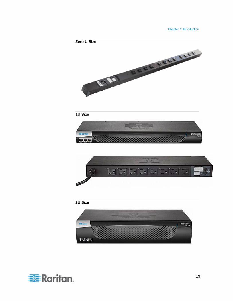
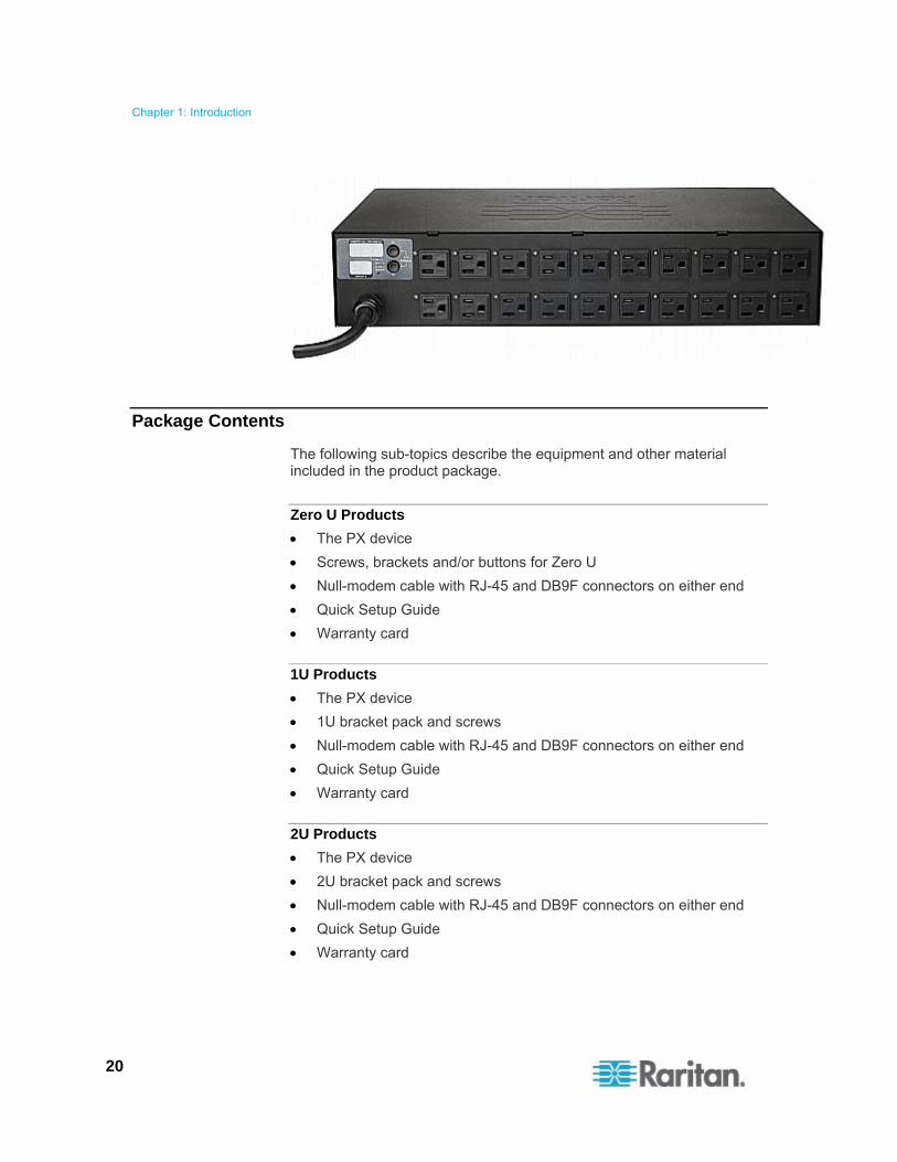
The PX comes in Zero U, 1U, and 2U sizes.
Chapter 1 Introduction
Chapter 1: Introduction
19
Zero U Size
1U Size
2U Size
Chapter 1: Introduction
20
Package Contents
The following sub-topics describe the equipment and other material included in the product package.
Zero U Products
The PX device
Screws, brackets and/or buttons for Zero U
Null-modem cable with RJ-45 and DB9F connectors on either end
Quick Setup Guide
Warranty card
1U Products
The PX device
1U bracket pack and screws
Null-modem cable with RJ-45 and DB9F connectors on either end
Quick Setup Guide
Warranty card
2U Products
The PX device
2U bracket pack and screws
Null-modem cable with RJ-45 and DB9F connectors on either end
Quick Setup Guide
Warranty card

21
This chapter describes how to rack mount a PX device. Only the most common rackmount methods are displayed. Follow the procedure suitable for your model.
In This Chapter
Rackmount Safety Guidelines .................................................................21 Circuit Breaker Orientation Limitation......................................................21 Standard Rackmount...............................................................................22 Mounting Zero U Models Using L-Brackets.............................................23 For Zero U Models Using Tool-less Button Mounting .............................24 Mounting Zero U Models Using Claw-Foot Brackets ..............................27 Mounting 1U or 2U Models......................................................................28
Rackmount Safety Guidelines
In Raritan products which require rack mounting, follow these precautions:
Operation temperature in a closed rack environment may be greater than room temperature. Do not exceed the rated maximum ambient temperature of the Power Distribution Units. See Specifications (on page 238) in the User Guide.
Ensure sufficient airflow through the rack environment.
Mount equipment in the rack carefully to avoid uneven mechanical loading.
Connect equipment to the supply circuit carefully to avoid overloading circuits.
Ground all equipment properly, especially supply connections, to the branch circuit.
Circuit Breaker Orientation Limitation
Usually a PDU can be mounted in any orientation. However, when mounting a PDU with circuit breakers, you must obey these rules:
Circuit breakers CANNOT face down. For example, do not horizontally mount a Zero U PDU with circuit breakers on the ceiling.
If a rack is subject to shock in environments such as boats or airplanes, the PDU CANNOT be mounted upside down. If installed upside down, shock stress reduces the trip point by 10%.
Note: If normally the line cord is down, upside down means the line cord is up.
Chapter 2 Rack-Mounting the PDU
Chapter 2: Rack-Mounting the PDU
22
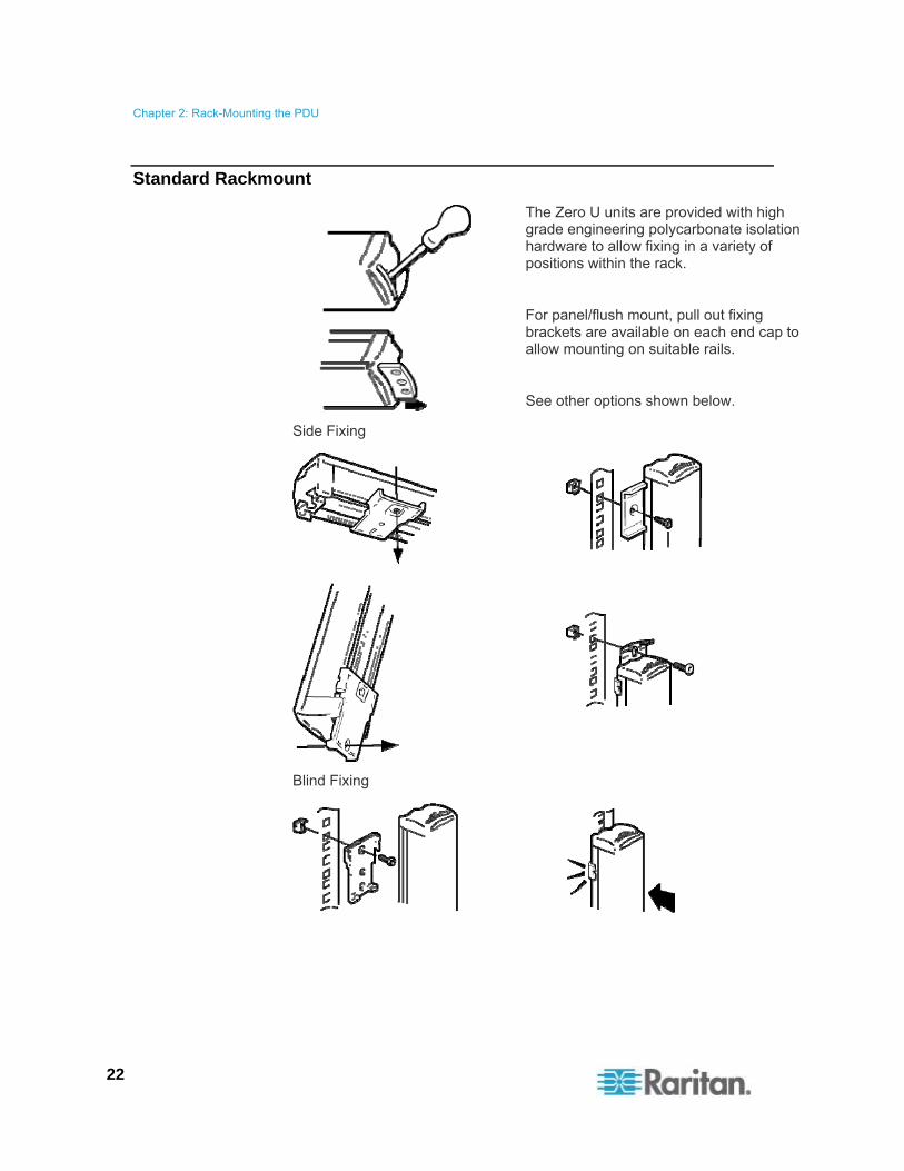
Standard Rackmount
The Zero U units are provided with high grade engineering polycarbonate isolation hardware to allow fixing in a variety of positions within the rack.
For panel/flush mount, pull out fixing brackets are available on each end cap to allow mounting on suitable rails.
See other options shown below.
Side Fixing
Blind Fixing

Chapter 2: Rack-Mounting the PDU
23
Mounting Zero U Models Using L-Brackets
If your PDU has circuit breakers implemented, read Circuit Breaker Orientation Limitation (on page 21) before mounting it.
To mount Zero U models using L-brackets:
1. Align the baseplates on the rear of the PX device.
2. Secure the baseplates in place. Different models ship with different types of baseplates.
To secure a baseplate with the thumbscrew, turn the thumbscrew until it is tightened.
To secure a baseplate without the thumbscrew, use the included L-shaped hex key to loosen the hex socket screws until the baseplate is fastened.

Chapter 2: Rack-Mounting the PDU
24
3. Align the L-brackets with the baseplates so that the five screw-holes on the baseplates line up through the L-bracket's slots. The rackmount side of brackets should face either the left or right side of the PX device.
4. Fasten the brackets in place with at least three screws (one through each slot). Use additional screws as desired.
5. Using rack screws, fasten the PX device to the rack through the L-brackets.
For Zero U Models Using Tool-less Button Mounting
Some Zero U PDUs ship with tool-less mounting brackets consisting of an adjustable baseplate with a large button. These work by attaching to the back side of a Zero U PX device (the side opposite of the outlets) and fitting the button into the mounting holes of the cabinet. Note that not all racks may allow the option of securing the PX device in this way.
Before You Begin Tool-less Mounting:
Ensure that you have sufficient space in the cabinet to mount the PX device. Approximately one inch of clearance is required at each end (top and bottom) of the device.
It may help to mark the back of the PX device through the mounting holes you intend to use. You can then use this mark to assist in aligning the silver buttons properly when attaching the base-plate.
Chapter 2: Rack-Mounting the PDU
25
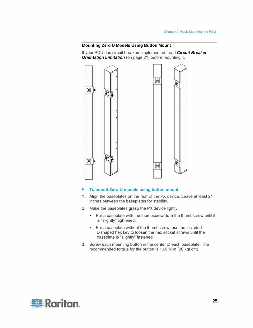
Mounting Zero U Models Using Button Mount
If your PDU has circuit breakers implemented, read Circuit Breaker Orientation Limitation (on page 21) before mounting it.
To mount Zero-U models using button mount:
1. Align the baseplates on the rear of the PX device. Leave at least 24 inches between the baseplates for stability.
2. Make the baseplates grasp the PX device lightly.
For a baseplate with the thumbscrew, turn the thumbscrew until it is "slightly" tightened.
For a baseplate without the thumbscrew, use the included L-shaped hex key to loosen the hex socket screws until the baseplate is "slightly" fastened.
3. Screw each mounting button in the center of each baseplate. The recommended torque for the button is 1.96 N·m (20 kgf·cm).

Chapter 2: Rack-Mounting the PDU
26
4. Align the large mounting buttons with the mounting holes in the cabinet, fixing one in place and adjusting the other.
5. Depending on the type of your baseplates, either further tighten the thumbscrews or loosen the hex socket screws until the mounting buttons are secured in their position.
6. Ensure that both buttons can engage their mounting holes simultaneously.
7. Press the PX device forward, pushing the mounting buttons through the mounting holes, then letting the device drop about 5/8". This secures the PX device in place and completes the installation.
Chapter 2: Rack-Mounting the PDU
27
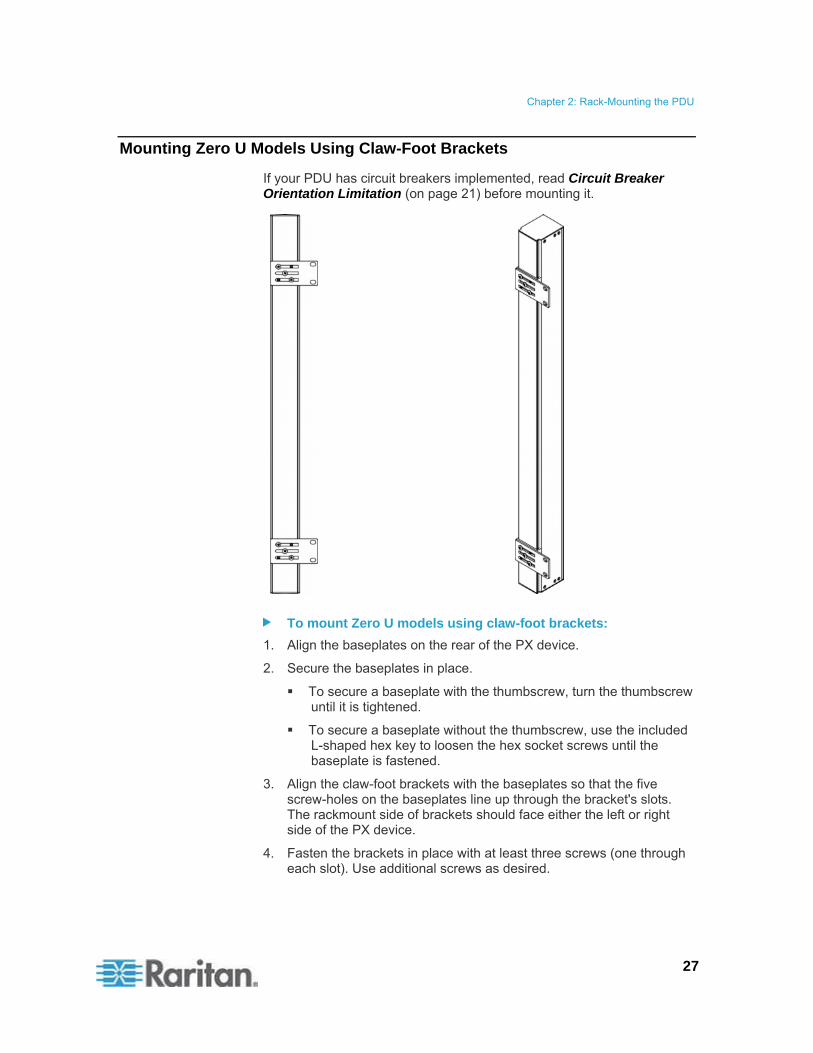
Mounting Zero U Models Using Claw-Foot Brackets
If your PDU has circuit breakers implemented, read Circuit Breaker Orientation Limitation (on page 21) before mounting it.
To mount Zero U models using claw-foot brackets:
1. Align the baseplates on the rear of the PX device.
2. Secure the baseplates in place.
To secure a baseplate with the thumbscrew, turn the thumbscrew until it is tightened.
To secure a baseplate without the thumbscrew, use the included L-shaped hex key to loosen the hex socket screws until the baseplate is fastened.
3. Align the claw-foot brackets with the baseplates so that the five screw-holes on the baseplates line up through the bracket's slots. The rackmount side of brackets should face either the left or right side of the PX device.
4. Fasten the brackets in place with at least three screws (one through each slot). Use additional screws as desired.
Chapter 2: Rack-Mounting the PDU
28
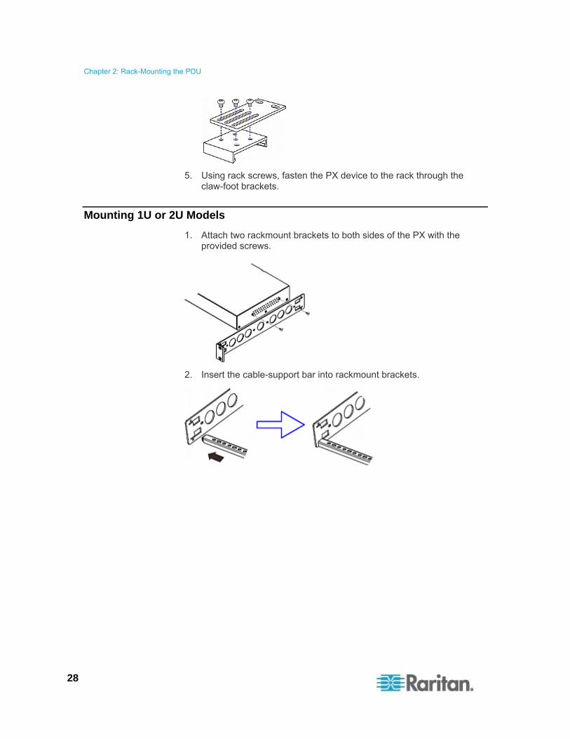
5. Using rack screws, fasten the PX device to the rack through the claw-foot brackets.
Mounting 1U or 2U Models
1. Attach two rackmount brackets to both sides of the PX with the provided screws.
2. Insert the cable-support bar into rackmount brackets.

Chapter 2: Rack-Mounting the PDU
29
3. Secure with the provided end cap screws.
4. Fasten the rackmount brackets' ears to the rack using your own fasteners.

30
This chapter explains how to install a PX device and configure it for network connectivity.
In This Chapter
Before You Begin ....................................................................................30 Connecting the PX to a Power Source....................................................31 Configuring the PX ..................................................................................32 Connecting DPX Environmental Sensor Packages (Optional)................41
Before You Begin
Before beginning the installation, perform the following activities:
Unpack the product and components
Prepare the installation site
Check the branch circuit rating
Fill out the equipment setup worksheet
Unpacking the Product and Components
1. Remove the PX device and other equipment from the box in which they were shipped. See Package Contents (on page 20) for a complete list of the contents of the box.
2. Compare the serial number of the equipment with the number on the packing slip located on the outside of the box and make sure they match.
3. Inspect the equipment carefully. If any of the equipment is damaged or missing, contact Raritan's Technical Support Department for assistance.
4. Verify that all circuit breakers on the PX device are set to ON. If not, turn them ON.
Or make sure that all fuses are inserted and seated properly. If there are any fuse covers, ensure that they are closed.
Note: Not all PX devices have overcurrent protection mechanisms.
Preparing the Installation Site
1. Make sure the installation area is clean and free of extreme temperatures and humidity.
Chapter 3 Installation and Configuration
Chapter 3: Installation and Configuration
31
Note: If necessary, contact Raritan Technical Support for the maximum operating temperature for your model. See Maximum Ambient Operating Temperature (on page 239).
2. Allow sufficient space around the PX device for cabling and outlet connections.
3. Review Safety Instructions (on page iii).
Checking the Branch Circuit Rating
The rating of the branch circuit supplying power to the PDU shall be in accordance with national and local electrical codes.
Filling Out the Equipment Setup Worksheet
An Equipment Setup Worksheet is provided in this User Guide. See Equipment Setup Worksheet (on page 241). Use this worksheet to record the model, serial number, and use of each IT device connected to the PDU.
As you add and remove devices, keep the worksheet up-to-date.
Connecting the PX to a Power Source
The distance between a PDU and its power source must be SHORTER than the PDU's line cord to avoid stretching out the cord. A locking connector used at the power source is highly recommended for a secure connection.
To connect a PDU to the power source:
1. Verify that all circuit breakers on the PX are set to ON. If not, turn them ON.
Or make sure that all fuses are inserted and seated properly. If there are any fuse covers, ensure that they are closed.
Note: Not all PX devices have overcurrent protection mechanisms.
2. Connect each PX to an appropriately rated branch circuit. See the label or nameplate affixed to your PX for appropriate input ratings or range of ratings.
3. With a 1U or 2U model, a blue power LED on the front panel is lit. A Zero U model does not have a similar power LED because it will be mounted in the back of a rack.
4. When a PX device powers up, it proceeds with the power-on self test and software loading for a few moments. At this time, the outlet LEDs cycle through different colors.
Chapter 3: Installation and Configuration
32
Note: If a PDU beeps after being powered up, either its circuit breaker has tripped or the L-N wiring is reversed. If no circuit breakers tripped, check the wiring of the plug adapter that is used or the direction in which the plug or plug adapter is plugged into the power socket.
5. When the software has completed loading, the outlet LEDs show a steady color and the front panel display illuminates.
Configuring the PX
There are two ways to initially configure a PX device:
Connect the PX to a computer to configure it. See Initial Network and Time Configuration (on page 34).
The computer must have a communications program such as HyperTerminal or PuTTY. In addition, you need a null-modem cable with RJ-45 and DB9F connectors on either end.
Connect the PX device to a TCP/IP network that supports DHCP, and use the IPv4 address and web browser to configure the PX. See Using the Web Interface (on page 54).
The DHCP-assigned IP address can be retrieved through the PX device's MAC address. You can contact your LAN administrator for assistance. See MAC Address (on page 286).
A Cat5e/6 UTP cable is required.
Note: The IP address of the PX is also retrievable by using the above first configuration method.

Chapter 3: Installation and Configuration
33
Connecting the PX to a Computer
To connect the PDU to the computer:
1. Connect the RJ-45 end of the null-modem cable to the port labeled Serial on the front of the PX device.

Chapter 3: Installation and Configuration
34
Item # Description
1 LAN Port
2 Serial Port
3 Feature Port
2. Connect the DB9 end of the null-modem cable to the serial port (COM) of the computer.
Note: If you plan to use this cable connection to log in to the command line interface, leave the cable connected after the configuration is complete.
Connecting the PX to Your Network
To use the web interface to administer the PX, you must connect the PX to your local area network (LAN).
To connect the PDU to the network:
1. Connect a standard Cat 5e UTP cable to the LAN port on the front of the PX device. See Connecting the PX to a Computer (on page 33) for the location of this port on your PDU.
2. Connect the other end of the cable to your LAN.
Initial Network and Time Configuration
After connecting the PX to your network, you must provide it with an IP address and some additional networking information.
If necessary, configure the NTP settings while determining the networking configuration.
To configure the networking parameters:
1. On the computer connected to the PX, open a communications program such as HyperTerminal or PuTTY.
2. Select the appropriate COM port, and set the following port settings:
Bits per second = 9600
Data bits = 8
Stop bits = 1
Parity = None
Flow control = None
Note: The “Flow control” parameter must be set to “None” to ensure that the communications program will work correctly with the PX.

Chapter 3: Installation and Configuration
35
3. Press Enter to display the opening prompt. Type config and press Enter.
4. You are prompted to assign a name to the PX.
Type a name and press Enter. The default name in parentheses is the PDU's serial number.
5. You are prompted to select an IP configuration method to get the IP address for the PDU.
To use an auto configuration method, type dhcp or bootp to let the DHCP or BOOTP server provide the IP address.
To use a static IP address, type none and assign the PDU an IP address. You will be prompted for the address, network mask, and gateway.
Note: The PX device's IP address is automatically displayed in the system prompt. The default static IP address is 192.168.0.192. The default IP configuration method is DHCP. The default IP address will be replaced by the address assigned by DHCP or BOOTP, or the static IP address you entered, when the configuration process is complete. To use the factory default IP address, select none as the IP autoconfiguration command, and accept the default value.
6. Then you are prompted to enable IP access control.
By default, IP access control is NOT enabled. This disables the PX firewall.

Chapter 3: Installation and Configuration
36
Leave the firewall disabled now. Later you can enable the firewall from the web interface and create firewall rules. See Configuring the Firewall (on page 119).
Tip: If you ever accidentally create a rule that locks you out of the PX, you can rerun the configuration program and reset this parameter to disabled to allow you to access the PX.
7. Press Enter. You are prompted to set the LAN interface speed.
By default, the LAN interface speed is set to auto, which allows the system to select the optimum speed.
To keep the default, press Enter.
To set the speed to 10 or 100 Mbps, type 10 or 100 and press Enter.
8. You are prompted to select the LAN interface duplex mode.
By default, the duplex mode is set to auto so that the system picks the optimum mode.
To keep the default, press Enter.
To specify half or full duplex, type half or full and press Enter.
Half duplex allows data to be transmitted to and from the PX, but not at the same time.
Full duplex allows data to be transmitted in both directions at the same time.

Chapter 3: Installation and Configuration
37
9. FIPS is disabled by default. Press Enter to leave it disabled, or type yes to enable it.
Note that after enabling the FIPS mode, the PX only supports the FIPS approved algorithms, which are defined in FIPS PUB 140-2. See Setting the FIPS Mode (on page 180).
10. The SNMP agent implemented on the PX is enabled by default.
To disable the SNMP agent, type no and press Enter.
To keep the default, press Enter. You are then prompted to enable or disable the SNMP v1/v2c and SNMP v3 protocols.
Note: SNMP v1/v2c is NOT supported by FIPS and thus becomes unavailable in the FIPS mode. See FIPS Limitations (on page 180).
After enabling the SNMP v1/v2c protocol, the PX prompts you to specify the read and write community strings. Default community strings include:
Read: raritan_public
Write: raritan_private
If enabling SNMP v3, the PX prompts you to determine whether to force the SNMP v3 encryption.
Exception: If "FIPS" has been enabled while enabling SNMP v3, the SNMP v3 encryption is automatically forced and is not user-configurable.

Chapter 3: Installation and Configuration
38
11. The system prompts you to specify the system location and contact person.
12. Determine whether to enable synchronization with NTP servers for date and time settings.
NTP synchronization: Type y if you want the date and time to sync up with NTP servers.
Manual configuration: Type n and you can set the date and time manually later through the PX web interface. See Setting the Date and Time (on page 76).

Chapter 3: Installation and Configuration
39
13. If choosing NTP synchronization in the previous step, a list of time zones is displayed for you to select. Type the number or the name of the desired time zone.
14. When prompted for the daylight savings time, type yes if the daylight savings time is applicable to your time zone, or type no to disable it.
15. You must determine which NTP servers to use if enabling NTP synchronization.
Auto-assigned NTP servers (default):
To use the NTP servers provided by the DHCP or BOOTP server, type yes or simply press Enter.
Manually-assigned NTP servers:
To manually specify NTP servers, type no. The system then prompts you to specify primary and secondary NTP servers.

Chapter 3: Installation and Configuration
40
A secondary NTP server is optional. You can simply press Enter for the secondary one if it is unavailable.
16. You are prompted to confirm the information you have entered.
All configuration parameters have been entered and are still displayed, so you can check the information you entered. Then do one of the following:
If the information is correct, type y to perform the configuration. A configuring device message is displayed.
If one or more parameters are incorrect, type n to return to the device name prompt shown in Step 4 so you can re-enter information.
To terminate the configuration process, type c. The configuration is canceled and you are returned to the opening prompt.
17. If you chose to perform the configuration, you will be returned to the opening prompt after the configuration is complete. Then you can use your PX.
Note: The IP address configured takes about at least 3 minutes to take effect for the PDU connected via the serial interface, or even longer if configured over DHCP.
Note: If the PX is connected to a Raritan KVM switch, and you want to disable that KVM switch's capability of monitoring and controlling the PDU, you can disable the connected power CIM using CLP commands. See Enabling or Disabling the Power CIM (on page 245).

Chapter 3: Installation and Configuration
41
Connecting DPX Environmental Sensor Packages (Optional)
To enable the detection of environmental factors around the PX, such as temperature or humidity, connect one or more Raritan's DPX environmental sensor packages to the PX.
Note that only DPX environmental sensor packages are supported. PX described in this User Guide does NOT support Raritan environmental sensors other than DPX sensor packages. See Applicable Models (on page xiv) for a list of PX models.
For detailed information on DPX sensor packages, see the Environmental Sensors Guide or Online Help in the Raritan website's PX2 section (https://www.raritan.com/support/product/px2).
The PX supports up to 16 managed DPX sensors.
Note: A DPX sensor package may contain more than one sensor. For example, the DPX-T3H1 sensor package contains three temperature sensors and one humidity sensor so there are four sensors per DPX-T3H1 package.
Use the sensor cable pre-installed (or provided) by Raritan to connect the environmental sensor packages to the PX. You MUST NOT extend or modify the sensor cable's length by using any tool other than the Raritan's DPX-ENVHUB4 sensor hubs. See Using an Optional DPX-ENVHUB4 Sensor Hub (on page 43).
All DPX sensor packages, except for DPX differential air pressure sensors, come with a factory-installed sensor cable with the RJ-12 connector.

Chapter 3: Installation and Configuration
42
Note: Web interface responsiveness may deteriorate when environmental sensor packages are connected to the PX.
To connect a DPX sensor package with a factory-installed sensor cable:
Plug the RJ-12 connector of the DPX sensor cable into the FEATURE (or SENSOR) port on the PX device.
Note: The port to connect environmental sensor packages is labeled FEATURE on most of the PX models, but labeled SENSOR on some new models.
To connect a DPX differential air pressure sensor:
1. Plug one end of a Raritan-provided phone cable into the IN port of a differential air pressure sensor.
2. Plug the other end of this phone cable into the FEATURE (or SENSOR) port on the PX.
The PX device
Raritan DPX differential air pressure sensor
Chapter 3: Installation and Configuration
43
Using an Optional DPX-ENVHUB4 Sensor Hub
The PX described hereby only supports Raritan's DPX-ENVHUB4 sensor hub. It does NOT support any other Raritan sensor hubs.
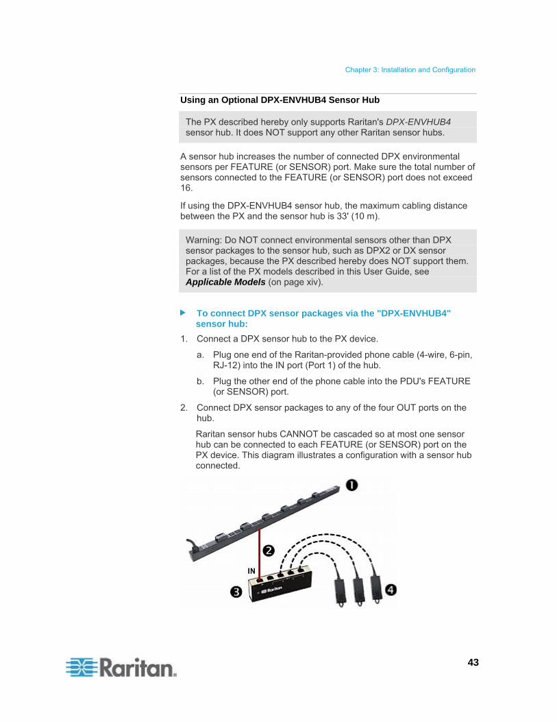
A sensor hub increases the number of connected DPX environmental sensors per FEATURE (or SENSOR) port. Make sure the total number of sensors connected to the FEATURE (or SENSOR) port does not exceed 16.
If using the DPX-ENVHUB4 sensor hub, the maximum cabling distance between the PX and the sensor hub is 33' (10 m).
Warning: Do NOT connect environmental sensors other than DPX sensor packages to the sensor hub, such as DPX2 or DX sensor packages, because the PX described hereby does NOT support them. For a list of the PX models described in this User Guide, see Applicable Models (on page xiv).
To connect DPX sensor packages via the "DPX-ENVHUB4" sensor hub:
1. Connect a DPX sensor hub to the PX device.
a. Plug one end of the Raritan-provided phone cable (4-wire, 6-pin, RJ-12) into the IN port (Port 1) of the hub.
b. Plug the other end of the phone cable into the PDU's FEATURE (or SENSOR) port.
2. Connect DPX sensor packages to any of the four OUT ports on the hub.
Raritan sensor hubs CANNOT be cascaded so at most one sensor hub can be connected to each FEATURE (or SENSOR) port on the PX device. This diagram illustrates a configuration with a sensor hub connected.

Chapter 3: Installation and Configuration
44
The PX device
Raritan-provided phone cable up to 33' (10 m) long
DPX-ENVHUB4 sensor hub
DPX sensor packages
45
This chapter explains how to use the PX device. It describes the LEDs and ports on the PDU, and explains how to use the front panel display. It also explains how the overcurrent protector works and when the beeper sounds.
In This Chapter
Panel Components ..................................................................................45 Circuit Breaker.........................................................................................51 Beeper .....................................................................................................53
Panel Components
The PX comes in Zero U, 1U, and 2U sizes. All types of models come with the following components on the outer panels.
Power cord
Outlets
Connection ports
LED display
Reset button
On 1U and 2U models, there is an additional component -- a blue power LED.
Blue LED
Only 1U and 2U models have a blue power LED on the right side of the front panel. This LED is lit solid as soon as the PX device is powered on.
Power Cord
Most of Raritan PDUs come with an installed power cord, which is ready to be plugged into an appropriate receptacle for receiving electricity. Such devices cannot be rewired by the user.
Connect each PX to an appropriately rated branch circuit. See the label or nameplate affixed to your PX for appropriate input ratings or range of ratings.
There is no power switch on the PX device. To power cycle the PDU, unplug it from the branch circuit, wait 15 seconds and then plug it back in.
Chapter 4 Using the PDU

Chapter 4: Using the PDU
46
Outlets
The total number of outlets varies from model to model. A small LED adjacent to each outlet indicates the outlet or PDU state. The PDU is shipped from the factory with all outlets turned ON. The table below explains how to interpret different outlet LED states.
LED state Outlet status What it means
Not lit (light grey) Powered OFF The outlet is not connected to power, or the control circuitry's power supply is broken.
Red ON and LIVE LIVE power. The outlet is on and power is available.
Red flashing ON and LIVE The current flowing through the outlet is greater than the upper warning (non-critical) threshold.
Green OFF and LIVE The outlet is turned off and power is available when the outlet is turned on.
Green flashing OFF and NOT LIVE The outlet is turned off and power is not available because the circuit breaker has tripped.
Yellow flashing ON and NOT LIVE The outlet is turned on but power is not available because a circuit breaker has tripped.
Cycling through Red, Green and Yellow
n/a
The PX device has just been plugged in and its management software is loading.
-- OR --
A firmware upgrade is being performed on the device.
Note: When a PX device powers up, it proceeds with the power-on self test and software loading for a few moments. At this time, the outlet LEDs cycle through different colors. When the software has completed loading, the outlet LEDs show a steady color and the front panel display illuminates.
Connection Ports
The three ports, from left to right, are labeled as SERIAL (RJ-45), FEATURE (RJ-12), and LAN (Ethernet, RJ-45). The table below explains what each port is used for.
Note that on some newer PX models, the FEATURE port is labeled SENSOR instead of FEATURE.

Chapter 4: Using the PDU
47
Port Used for...
SERIAL Establishing a serial connection between a computer and the PX device:
Take the null-modem cable that was shipped with the PX device, connect the end with the RJ-45 connector to the RS-232 serial port on the PX device, and connect the end with the DB9F connector to the serial (COM) port on the computer.
The serial port is also used to interface with some Raritan access products (such as the Dominion KX) through the use of a power CIM.
FEATURE or SENSOR
Connection to Raritan's environmental sensor packages.
LAN Connecting the PX device to your company's network:
Connect a standard Cat5e/6 UTP cable to this port and connect the other end to your network. This connection is necessary to administer or access the PX device remotely using the web interface.
There are two small LEDs adjacent to the port:
Green indicates a physical link and activity.
Yellow indicates communications at 10/100 BaseT speeds.
Note: Connecting any power CIM except for the D2CIM-PWR (such as P2CIM-PWR) to the PX serial port causes all outlets to switch ON state, even if they were previously OFF.
LED Display
The LED display is located on the side where outlets are available.
The following picture shows the LED display.
Chapter 4: Using the PDU
48
The LED display consists of:
A row displaying three digits
A row displaying two digits
Up and Down buttons
Three-Digit Row
The three-digit row shows the readings for the selected component. Values that may appear include:
Current, voltage, or active power of the selected outlet
Current of the selected line or circuit breaker
The text “FuP,” which indicates that the Firmware uPgrade is being performed
The text "CbE," which indicates the circuit breaker associated with the selected outlet has tripped or the fuse has blown
For unbalanced load on a three-phase PDU:
The text "nE," which indicates the unbalanced load feature is not Enabled.
Note: To enable the unbalanced load detection, see Enabling Unbalanced Load Detection (on page 115).
The text "nA," which indicates the unbalanced load reading is not Available because there is no load connected to the selected outlet/inlet.
Two-Digit Row
The two-digit row shows the number of the currently selected outlet, line or circuit breaker. Values that may appear include:
Two-digit numbers: This indicates the selected outlet. For example, 03 indicates outlet 3.
Cx: This indicates the selected circuit breaker, where x is the circuit breaker number. For example, C1 represents Circuit Breaker 1.
Lx: This indicates the selected line, where x is the line number. For example, L2 represents Line 2.
Note: For a single-phase model, L1 current represents the Unit Current.
uL: This represents the inlet's Unbalanced Load, which is only available for a three-phase PDU.
Note: To enable the unbalanced load detection, see Enabling Unbalanced Load Detection (on page 115).
Chapter 4: Using the PDU
49
For a three-phase inline monitor:
xa: This indicates either the L1 current, or L1-N or L1-L2 voltage of the selected outlet/inlet, where x is the outlet/inlet number. For example, 3a represents the outlet/inlet 3's L1 current, or L1-N or L1-L2 voltage.
xb: This indicates either the L2 current, or L2-N or L2-L3 voltage of the selected outlet/inlet, where x is the outlet/inlet number. For example, 1b represents the outlet/inlet 1's L2 current, or L2-N or L2-L3 voltage.
xc: This indicates either the L3 current, or L3-N or L3-L1 voltage of the selected outlet/inlet, where x is the outlet/inlet number. For example, 2c represents the outlet/inlet 2's L3 current, or L3-N or L3-L1 voltage.
xU: This indicates the unbalanced load of the selected outlet/inlet, where x is the outlet/inlet number. For example, 1U represents the outlet/inlet 1's unbalanced load.
xP: This indicates the active power of the selected outlet/inlet, where x is the outlet/inlet number. For example, 1P represents the outlet/inlet 1's active power.
For information on in-line monitors, see In-line Monitors (on page 222).
Automatic Mode
When left alone, the LED display cycles through the line readings and circuit breaker readings, as available for your PX model. This is the Automatic Mode.

Chapter 4: Using the PDU
50
Manual Mode
You can press the Up or Down button to enter the Manual Mode so that a particular outlet, line or circuit breaker can be selected to show specific readings.
Note that the outlet active power reading shown in the LED display is the 'average' value of active power readings of the selected outlet. In the beginning, the 'average' active power is smaller than the 'instantaneous' active power because initial active power readings have been zero for a certain period of time. Then the 'average' value slowly builds for over 30 seconds and becomes stable when the 'average' active power is nearly the same as the 'instantaneous' active power.
Note: It is faster for the PDU to show a stable active power reading in the web interface than on the LED display because the web interface shows an "instantaneous" value while the LED display shows an "average" value.
To operate the LED display:
1. Press the Up or Down button until the desired outlet, line or circuit breaker number is selected in the two-digit row.
Pressing the Up button moves up one selection.
Pressing the Down button moves down one selection.
2. Current of the selected component is shown in the three-digit row. It appears in this format: XX.X (A).
3. If you select an outlet, you can press the Up and Down buttons simultaneously to switch between the voltage, active power and current readings.
The voltage appears in this format: XXX (V). It is displayed for about five seconds, after which the current reading re-appears.
The active power appears in this format: X.XX (W). It is displayed for about five seconds, after which the current reading re-appears.
Tip: A quick way to distinguish between voltage, current, and power is the placement of the decimal point in the display. Voltage has no decimal point, active power has a decimal point between the first and second digits, and current has a decimal point between the second and third digits.
Note: The LED display returns to the Automatic Mode after 10 seconds elapse since the last time any button was pressed.

Chapter 4: Using the PDU
51
Reset Button
The reset button is located inside the small hole near the display panel on the PDU.
Pressing this reset button restarts the PX device's software without any loss of power to outlets. It does not reset the PX device to factory defaults.
Tip: To reset the PDU to factory defaults, see Resetting to Factory Defaults (on page 298).
Circuit Breaker
PX models rated over 20A (North American) or 16A (international) contain overcurrent protectors for outlets, which are usually branch circuit breakers. These circuit breakers automatically trip (disconnect power) when the current flowing through the circuit breaker exceeds its rating.
If the circuit breaker switches off power, the front panel display shows:
CbE, which means "circuit breaker error."
The lowest outlet number affected by the circuit breaker error.
You are still able to switch between outlets on the PDU's display panel when the circuit breaker error occurs. Outlets affected by the error show CbE. Unaffected outlets can show diverse sensor readings properly.
When a circuit breaker trips, power flow ceases to all outlets connected to it. You must manually reset the circuit breaker so that affected outlets can resume normal operation.
Depending on the model you purchased, the circuit breaker may use a button- or handle-reset mechanism.
Resetting the Button-Type Circuit Breaker
Your button-type circuit breakers may look slightly different from the images shown in this section, but the reset procedure remains the same.
To reset the button-type breakers:
1. Locate the breaker whose ON button is up, indicating that the breaker has tripped.
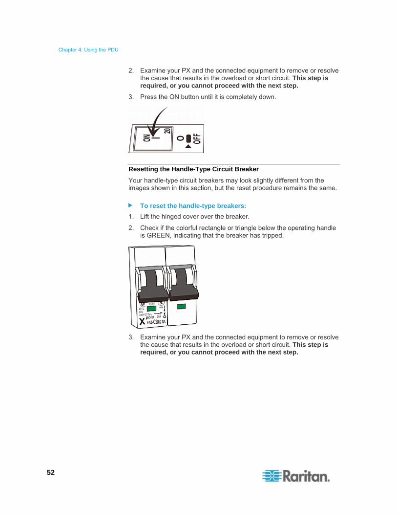
Chapter 4: Using the PDU
52
2. Examine your PX and the connected equipment to remove or resolve the cause that results in the overload or short circuit. This step is required, or you cannot proceed with the next step.
3. Press the ON button until it is completely down.
Resetting the Handle-Type Circuit Breaker
Your handle-type circuit breakers may look slightly different from the images shown in this section, but the reset procedure remains the same.
To reset the handle-type breakers:
1. Lift the hinged cover over the breaker.
2. Check if the colorful rectangle or triangle below the operating handle is GREEN, indicating that the breaker has tripped.
3. Examine your PX and the connected equipment to remove or resolve the cause that results in the overload or short circuit. This step is required, or you cannot proceed with the next step.

Chapter 4: Using the PDU
53
4. Pull up the operating handle until the colorful rectangle or triangle turns RED.
Beeper
The PX includes a beeper to issue an audible alarm when a significant situation occurs.
The beeper sounds an alarm within 3 seconds of a circuit breaker trip.
It also sounds an alarm when the control board temperature sensor reaches the non-critical threshold -- default is 65 degrees Celsius (149 degrees Fahrenheit).
Note: The temperature thresholds are factory defaults and can be user-configurable. See Setting PDU Thresholds and Hysteresis (on page 112).
The beeper stops ringing after the significant situation disappears.
The beeper stops as soon as all circuit breakers have been reset.
If the alarm is caused by the control board's high temperature, it stops after the control board temperature sensor drops below the non-critical threshold.
A Note about the Non-Critical Temperature Threshold Alarm
The PX automatically shuts down its CPU when the control board temperature sensor reaches 87 degrees Celsius (188.6 degrees Fahrenheit). In order to alert you of the impending critical thermal shutdown issue for handling the situation promptly, the beeper sounds an alarm once the temperature sensor reaches the non-critical threshold.

54
This chapter explains how to use the web interface to administer a PX.
In This Chapter
Logging in to the Web Interface ..............................................................54 Web Interface Elements ..........................................................................58 Using the Home Page .............................................................................64 Measurement Accuracy...........................................................................69 Managing the PX .....................................................................................69 Setting Up User Profiles ..........................................................................93 Setting Up User Groups ..........................................................................99 Setting Up and Managing Outlets .........................................................104 Setting Up Power Thresholds and Hysteresis.......................................112 Monitoring Line and Circuit Breaker Status...........................................114 Access Security Control ........................................................................118 Setting Up a Digital Certificate...............................................................129 Setting Up External Authentication........................................................133 DPX Environmental Sensor Packages..................................................140 Configuring and Using Alert Notifications..............................................154 Setting Up Event Logging......................................................................168 Outlet Grouping .....................................................................................175 Setting the FIPS Mode ..........................................................................180 Disabling IPMI over LAN .......................................................................182 Diagnostics ............................................................................................183 Using Online Help..................................................................................187
Logging in to the Web Interface
To log in to the web interface, you must enter a user name and password. The first time you log in to the PX, use the default user name (admin) and password (raritan). You are then prompted to change the password for security purposes.
After successfully logging in, you can create user profiles for your other users. These profiles define their login names and passwords. See Creating a User Profile (on page 94).
Chapter 5 Using the Web Interface

Chapter 5: Using the Web Interface
55
Unsupported Web Browsers
You can launch either Microsoft Internet Explorer® or Mozilla Firefox to access the PX web interface.
The PX no longer supports some web browsers as of release 1.5.20, especially outdated versions of web browsers.
Web browsers NOT supported by PX:
Internet Explorer 7 (IE7) or earlier
Internet Explorer 9 (IE9)
Mozilla Firefox 13.0.1 or earlier
Google Chrome
Login
The web interface allows a maximum of 16 users to log in simultaneously. However, the PX performance may degrade when there are more than three simultaneous user sessions. For an acceptable performance, it is recommended to NOT exceed three simultaneous user sessions.
To log in to the web interface:
1. Open a browser, such as Microsoft Internet Explorer or Mozilla Firefox, and type this URL:
http(s)://<ip address>
where <ip address> is the IP address of your PX.
2. If a security alert message appears, click OK or Yes to accept. The Login page then opens.

Chapter 5: Using the Web Interface
56
3. Type your user name and password in the Username and Password fields.
Note: Both the user name and password are case sensitive.
4. Click Login. The Home page opens.

Chapter 5: Using the Web Interface
57
Note: Depending on your model type and hardware configuration, elements shown on your Home page may appear differently from this image.
You must enable JavaScript in the web browser for proper operation. If Java Script is not enabled, features such as the Status Panel on the left side of the interface does not display correctly.
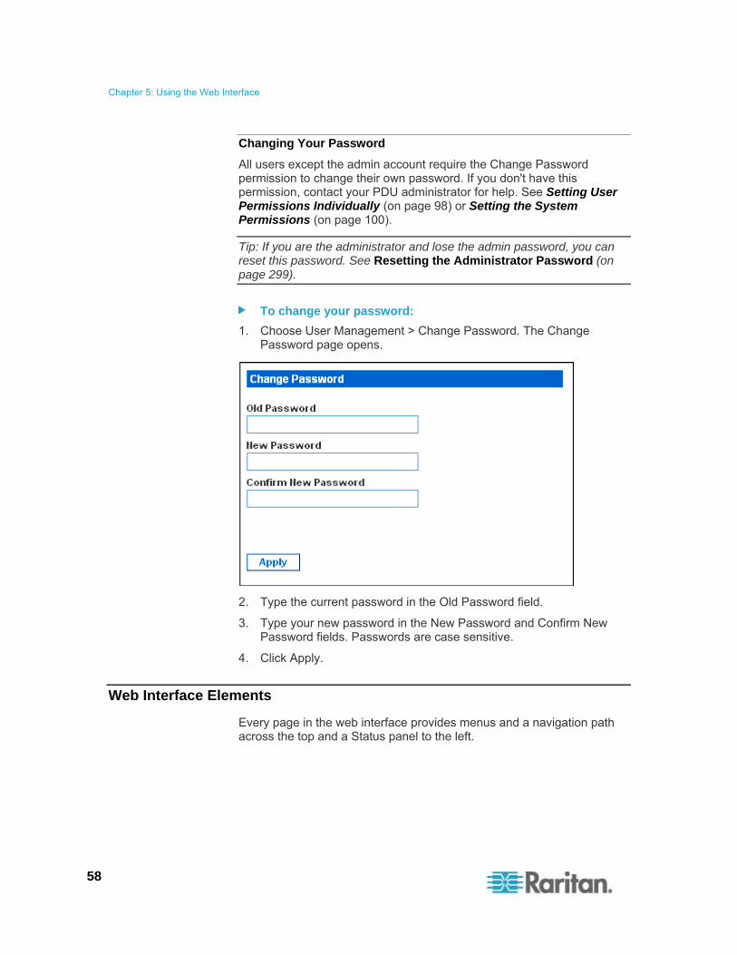
Chapter 5: Using the Web Interface
58
Changing Your Password
All users except the admin account require the Change Password permission to change their own password. If you don't have this permission, contact your PDU administrator for help. See Setting User Permissions Individually (on page 98) or Setting the System Permissions (on page 100).
Tip: If you are the administrator and lose the admin password, you can reset this password. See Resetting the Administrator Password (on page 299).
To change your password:
1. Choose User Management > Change Password. The Change Password page opens.
2. Type the current password in the Old Password field.
3. Type your new password in the New Password and Confirm New Password fields. Passwords are case sensitive.
4. Click Apply.
Web Interface Elements
Every page in the web interface provides menus and a navigation path across the top and a Status panel to the left.

Chapter 5: Using the Web Interface
59
Menus
There are several menus in the web interface, each with their own set of menu items:
Details
Outlet Details
Line Details
CB Details
PDU Details
Outlet Setup
Alerts
Alert Configuration
Alert Policies
Alert Policy Editor
Alert Destinations
User Management
Change Password
Users & Groups
User/Group System Permissions
User/Group Outlet Permissions
Device Settings
PDU Setup
Network
Security
Certificate
Date/Time
Authentication
SMTP Settings
SNMP Settings
Event Log
FIPS Setting
External Sensors
External Sensors Details
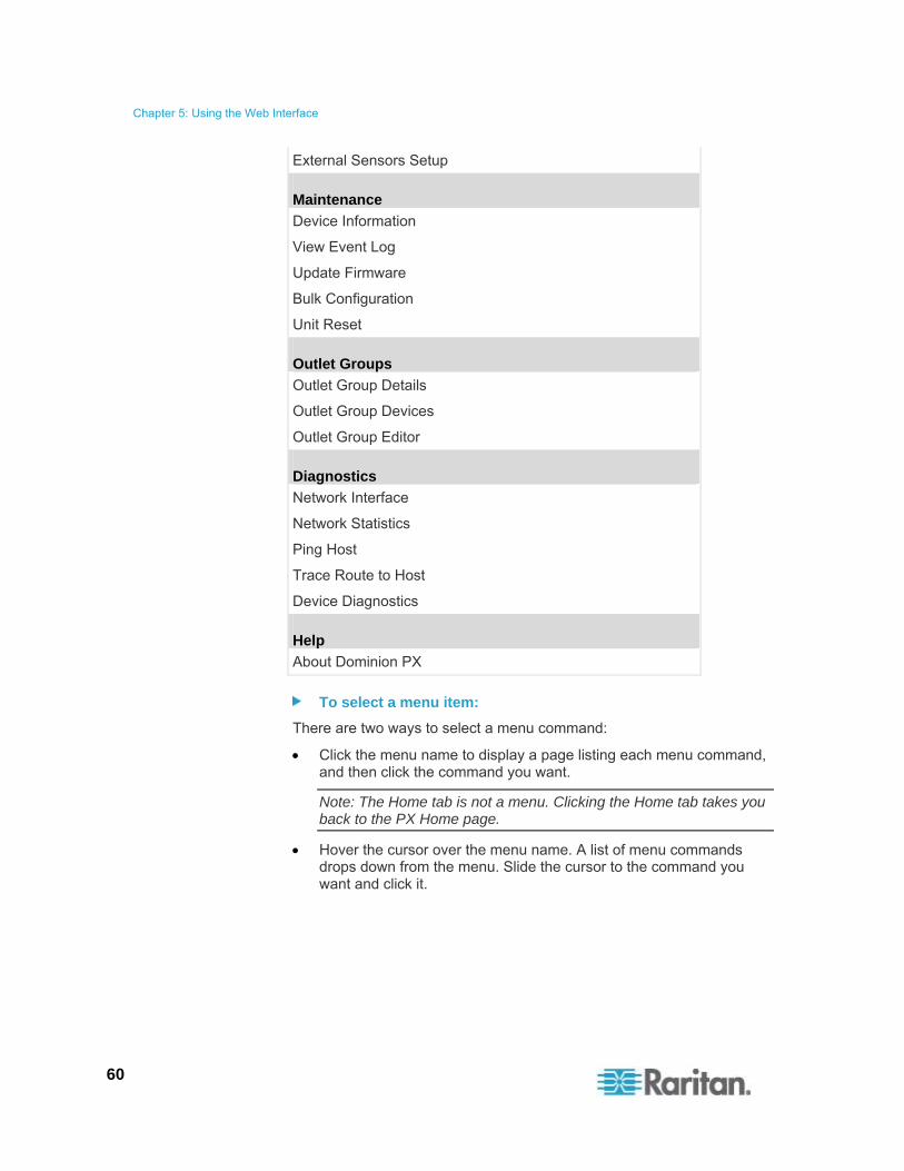
Chapter 5: Using the Web Interface
60
External Sensors Setup
Maintenance
Device Information
View Event Log
Update Firmware
Bulk Configuration
Unit Reset
Outlet Groups
Outlet Group Details
Outlet Group Devices
Outlet Group Editor
Diagnostics
Network Interface
Network Statistics
Ping Host
Trace Route to Host
Device Diagnostics
Help
About Dominion PX
To select a menu item:
There are two ways to select a menu command:
Click the menu name to display a page listing each menu command, and then click the command you want.
Note: The Home tab is not a menu. Clicking the Home tab takes you back to the PX Home page.
Hover the cursor over the menu name. A list of menu commands drops down from the menu. Slide the cursor to the command you want and click it.

Chapter 5: Using the Web Interface
61
Navigation Path
When you select a menu command and navigate to a specific page, the system displays a navigation path across the top that shows the menu and menu command you selected to get there.
For example, if you choose User Management > User/Group System Permissions, the navigation path looks like the following example.
To return to a previous page, click the page name in the navigation path. Every navigation path begins at the Home page, so a single click on "Home" always takes you back to the Home page from anywhere in the interface. You can also click the Home tab from any page to take you back to the Home page.
Status Panel
The Status panel appears on the left of every page in the interface. It shows:
Present date and time
Information about the user, including:
User name
User's present state (active, idle, and so on)
IP address of the user's computer
Date and time of the user's last login
Information about the PX device, including:
PDU name
Model name and number
IP address
Firmware version
Firmware status
FIPS mode enabled (displayed in blue) or disabled (displayed in black)
IPMI over LAN enabled (displayed in blue) or disabled (displayed in black)
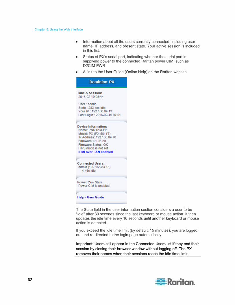
Chapter 5: Using the Web Interface
62
Information about all the users currently connected, including user name, IP address, and present state. Your active session is included in this list.
Status of PX's serial port, indicating whether the serial port is supplying power to the connected Raritan power CIM, such as D2CIM-PWR
A link to the User Guide (Online Help) on the Raritan website
The State field in the user information section considers a user to be "idle" after 30 seconds since the last keyboard or mouse action. It then updates the idle time every 10 seconds until another keyboard or mouse action is detected.
If you exceed the idle time limit (by default, 15 minutes), you are logged out and re-directed to the login page automatically.
Important: Users still appear in the Connected Users list if they end their session by closing their browser window without logging off. The PX removes their names when their sessions reach the idle time limit.

Chapter 5: Using the Web Interface
63
Note: If any PSoC update failure occurs during the firmware upgrade process, the failure is reported in the status panel. See PSoC Firmware Upgrade Failure (on page 88).
Status Messages
When you perform an operation from the web interface, such as creating a user profile or changing a network setting, a message appears at the top of the page indicating whether or not the operation was successful. Be sure to check this message to confirm that an operation was successful.
Successful Messages
The following is an example of a status message after an operation has completed successfully:
Unsuccessful Messages
The following is an example of a status message after an operation has been performed unsuccessfully:
Unavailable Options
Sometimes certain actions are unavailable. When this occurs, the appropriate buttons are non-functional, though different browsers may display this differently. For example, if you select the Admin User Group in Internet Explorer, the buttons for Copy, Modify, and Delete are grayed-out since you cannot Copy, Modify, or Delete the Admin user group. In Firefox, these buttons appear normal, but are unclickable.
Reset to Defaults
Many pages provide a Reset To Defaults button that returns all fields to their default values. If you use this button, you must click the Apply button afterward to save the defaults. If you do not, these fields retain the non-default values.

Chapter 5: Using the Web Interface
64
Default Asterisk
If a field has an asterisk after it, as shown below,
then this field is currently set to its default value. If you change the default, the asterisk disappears. If you reset it to the default, the asterisk returns.
Refresh
Many pages provide a Refresh button. If a page is open for a while, the information displayed may become "stale." Click this button periodically to reload the page and update the information displayed.
Using the Home Page
The Home page is the first page to appear after a successful login. It consists of a Lines Loads display, Circuit Breakers status (if applicable), an Outlets list, and an All Outlets Control panel. The page also contains an External Sensors panel when Raritan's DPX environmental sensor packages are connected to the PX. The Home page refreshes every 30 seconds to keep the data displayed up to date.
You can return to the Home page from any other page in the web interface by clicking:
The Home tab at the top of the window
The Home link in the navigation path - see Navigation Path (on page 61)
The Raritan logo in the upper left of the window
The product name "Dominion PX" under the Raritan logo
Line Loads Display
The Line Loads display shows the current load on each of the PX current-carrying lines.

Chapter 5: Using the Web Interface
65
The status of each line is represented by a status bar. As the load on the line increases, the colored portion grows to fill the bar. A status bar that is nearly full indicates that the particular line is approaching its rated current limit. The colored portion of the bar also changes colors as the load crosses configured thresholds.
For more information on the status of each line, choose Details > Line Details.
Circuit Breaker Status
For PX models with circuit breakers, a circuit breaker status display appears on the Home page. This provides a quick view of each circuit breaker's status and the current handled by each circuit breaker.
A status of Closed indicates that the circuit is closed and functioning properly.
A status of Open and a change in color indicates that a circuit breaker has tripped.
For details on each circuit breaker, choose Details > CB Details.
Tip: The most efficient use of the PX occurs when current loads are balanced between all circuit breakers. Using the Outlet Mapping on the CB Details page, and the Circuit Breaker status on the Home Page, you can arrange where devices are plugged into the PX in order to maintain that balance.
Note: The current drawn through a circuit breaker indicates the amount of current flowing to a bank of outlets. In three-phase PX models, this number does not match the current draw on each line since each bank of outlets is tied to two lines.

Chapter 5: Using the Web Interface
66
Outlets List
The Outlets list displays each outlet on the PX device as a table row with a view of the power status, the RMS current, and the RMS Power through the individual outlet.
Note: RMS refers to Root Mean Square, a statistical method for measuring certain types of variables. In this context, it gives the value of current that is equivalent to a DC value.
Turning On or Off an Outlet, or Cycling the Power
You can use the outlets list on the Home page to control the power state of individual outlets.
Note: Not all PX PDUs support the outlet switching function. For example, PX-4nnn and PX-3nnn (where n is a number) do NOT support outlet switching.
On a three-phase "delta" model, it is likely an overcurrent warning message appears when you try to turn on an outlet. For details, see Current Warning on a Three-Phase Delta Model (on page 68).
To turn an outlet on, off, or cycle the power
1. Click On, Off, or Cycle.
2. A dialog for confirming the operation appears. Click OK and the outlet switches ON or OFF, or cycles its power.
Chapter 5: Using the Web Interface
67
Tip: You can also turn an outlet on or off or power cycle it from the Outlet Details page. See Turning an Outlet On or Off (on page 112) and Power Cycling an Outlet (on page 111).
Displaying Additional Details
To display additional details about an outlet, click the outlet name. This displays the Outlet Details page. This page shows the name, status and line pair of the outlet, as well as:
RMS Current
Power Factor
Maximum RMS Current
Voltage
Active Power
Note: It is faster for the PDU to show a stable active power reading in the web interface than on the LED display because the web interface shows an "instantaneous" value while the LED display shows an "average" value.
Apparent Power
Active Energy (applicable on some models following the PX-nnnn format, where n is a number)
The circuit breaker associated with the PDU, if available, is also indicated on this page.
Note: RMS refers to Root Mean Square, a statistical method for measuring certain types of variables. In this context, it gives the value of current that is equivalent to a DC value.

Chapter 5: Using the Web Interface
68
Current Warning on a Three-Phase Delta Model
On a three-phase delta model, the following warning message may appear when attempting to turn on an outlet.
Performing this operation may exceed the allowable current for this line and/or the circuit breaker protecting this group of outlets. Do you wish to continue?
This is because each bank of outlets on a three-phase delta model draws current from two lines as illustrated in the following diagram, and one of the lines associated with the outlet you are going to turn on already has some load attached.
For example, if you have connected any device to outlet bank A, which draws current from L1 and L2, when trying to turn on any outlet in bank B, which draws current from L2 and L3, the above-mentioned warning appears to remind you that it is likely the newly added load in bank B may cause L2 to exceed allowable current because both banks A and B draw current from L2.
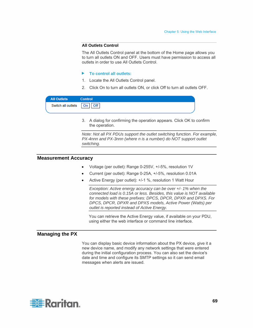
Chapter 5: Using the Web Interface
69
All Outlets Control
The All Outlets Control panel at the bottom of the Home page allows you to turn all outlets ON and OFF. Users must have permission to access all outlets in order to use All Outlets Control.
To control all outlets:
1. Locate the All Outlets Control panel.
2. Click On to turn all outlets ON, or click Off to turn all outlets OFF.
3. A dialog for confirming the operation appears. Click OK to confirm the operation.
Note: Not all PX PDUs support the outlet switching function. For example, PX-4nnn and PX-3nnn (where n is a number) do NOT support outlet switching.
Measurement Accuracy
Voltage (per outlet): Range 0-255V, +/-5%, resolution 1V
Current (per outlet): Range 0-25A, +/-5%, resolution 0.01A
Active Energy (per outlet): +/-1 %, resolution 1 Watt Hour
Exception: Active energy accuracy can be over +/- 1% when the connected load is 0.15A or less. Besides, this value is NOT available for models with these prefixes: DPCS, DPCR, DPXR and DPXS. For DPCS, DPCR, DPXR and DPXS models, Active Power (Watts) per outlet is reported instead of Active Energy.
You can retrieve the Active Energy value, if available on your PDU, using either the web interface or command line interface.
Managing the PX
You can display basic device information about the PX device, give it a new device name, and modify any network settings that were entered during the initial configuration process. You can also set the device's date and time and configure its SMTP settings so it can send email messages when alerts are issued.

Chapter 5: Using the Web Interface
70
Displaying Basic Device Information
To display basic information about a PX:
1. Choose Maintenance > Device Information. The Device Information page opens.
2. The Device Information panel displays the product name, serial number, and IP and MAC addresses of the PX device, as well as detailed information about the firmware running in the PDU.
3. To open or save an XML file providing details for Raritan Technical Support, click the "View the datafile for support" link.
Tip: Below the Device Information panel is the Model Configuration panel. See Displaying Model Configuration Information (on page 71).
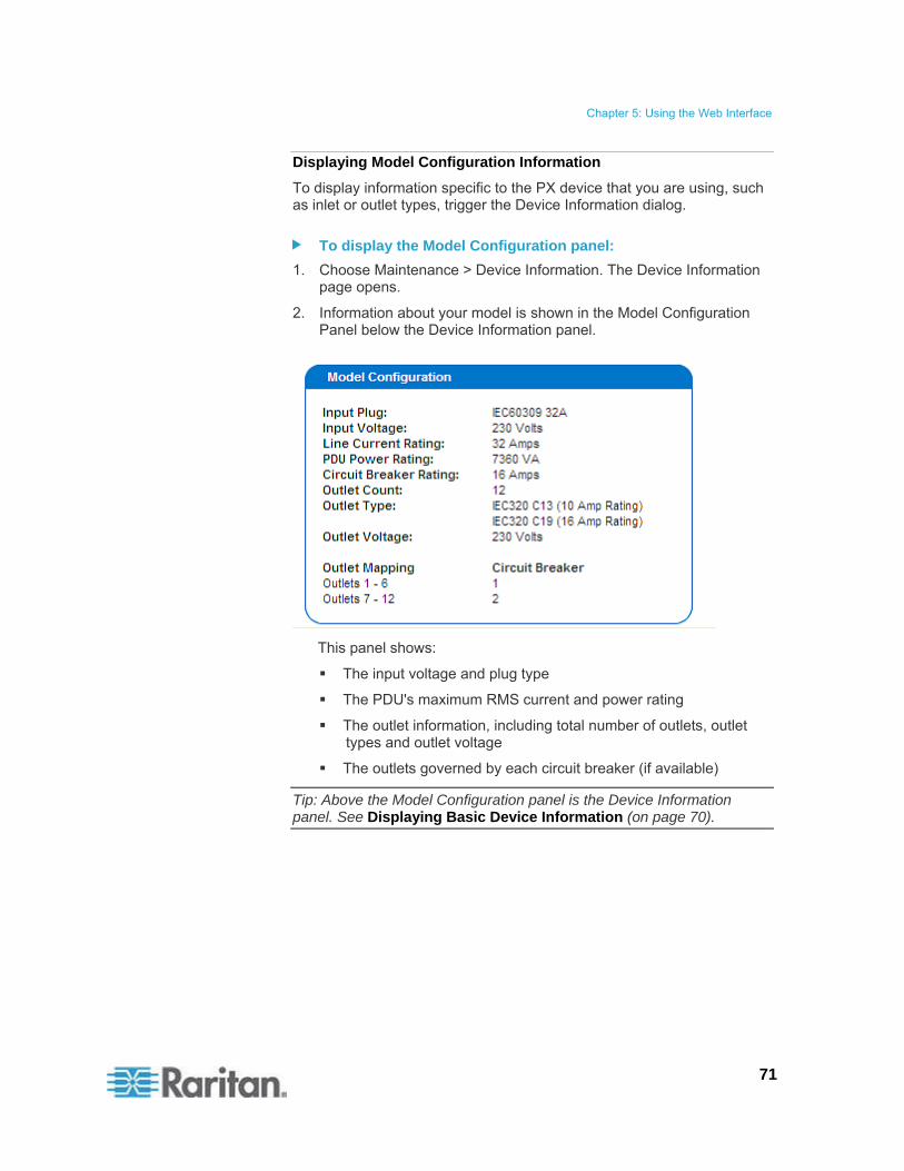
Chapter 5: Using the Web Interface
71
Displaying Model Configuration Information
To display information specific to the PX device that you are using, such as inlet or outlet types, trigger the Device Information dialog.
To display the Model Configuration panel:
1. Choose Maintenance > Device Information. The Device Information page opens.
2. Information about your model is shown in the Model Configuration Panel below the Device Information panel.
This panel shows:
The input voltage and plug type
The PDU's maximum RMS current and power rating
The outlet information, including total number of outlets, outlet types and outlet voltage
The outlets governed by each circuit breaker (if available)
Tip: Above the Model Configuration panel is the Device Information panel. See Displaying Basic Device Information (on page 70).
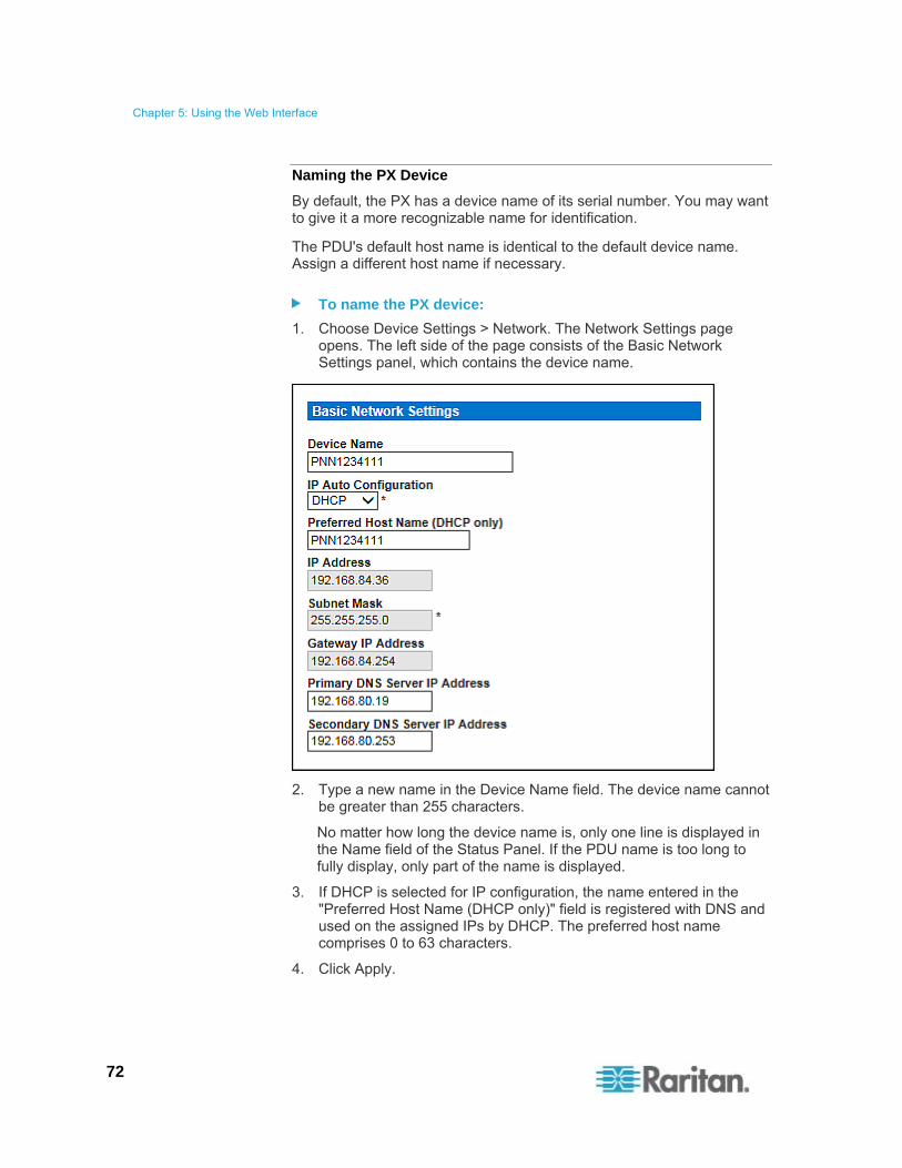
Chapter 5: Using the Web Interface
72
Naming the PX Device
By default, the PX has a device name of its serial number. You may want to give it a more recognizable name for identification.
The PDU's default host name is identical to the default device name. Assign a different host name if necessary.
To name the PX device:
1. Choose Device Settings > Network. The Network Settings page opens. The left side of the page consists of the Basic Network Settings panel, which contains the device name.
2. Type a new name in the Device Name field. The device name cannot be greater than 255 characters.
No matter how long the device name is, only one line is displayed in the Name field of the Status Panel. If the PDU name is too long to fully display, only part of the name is displayed.
3. If DHCP is selected for IP configuration, the name entered in the "Preferred Host Name (DHCP only)" field is registered with DNS and used on the assigned IPs by DHCP. The preferred host name comprises 0 to 63 characters.
4. Click Apply.

Chapter 5: Using the Web Interface
73
Note: Device name shown in the web interface should be identical to the SNMP system name. However, the SNMP system name becomes inconsistent with the device name after the device name in the web interface is changed. To make both names identical, you must restart the PX device or restart the SNMP agent after changing the device name.
Modifying the Network Settings
The PX was configured for network connectivity during the installation and configuration process. See Configuring the PX (on page 32). If necessary, you can modify any network settings using the web interface.
To modify the network settings:
1. Choose Device Settings > Network. The Network Settings page opens.
The left side of the page contains the Basic Network Settings panel, which shows the current network settings. See Naming the PX Device (on page 72) for details on this panel.
2. Do either of the following:
Auto configuration: To auto-configure the PX device, select DHCP or BOOTP in the IP Auto Configuration field.
- With DHCP selected, you can enter a preferred DHCP host name comprising a maximum of 63 characters, which is optional.
Static IP: To enter a static IP address, select None in the IP Auto Configuration field, and then enter:
- IP address
- Subnet mask
- Gateway address
- Primary and (optional) secondary DNS servers' addresses
Note: The Subnet Mask field supports Variable Length Subnet Mask (VLSM).
3. When you are finished, click Apply.

Chapter 5: Using the Web Interface
74
Role of a DNS Server
As Internet communications are carried out on the basis of IP addresses, appropriate DNS server settings are required for mapping domain names (host names) to corresponding IP addresses, or the PX may fail to connect to the given host.
Therefore, DNS server settings are important for external authentication. With appropriate DNS settings, the PX can resolve the external authentication server's name to an IP address for establishing a connection. If the SSL/TLS encryption is enabled, the DNS server settings become critical since only fully qualified domain name can be used for specifying the LDAP server.
For information on external authentication, see Setting Up External Authentication (on page 133).
Modifying Network Service Settings
The PX supports these network communication services: HTTPS, HTTP, Telnet and SSH.
HTTPS and HTTP enable the access to the web interface. Telnet and SSH enable the access to the command line interface. See Using the CLP Interface (on page 206).
By default, SSH is enabled, Telnet is disabled, and all TCP ports for supported services are set to standard ports. You can change default settings if necessary.
Note: Telnet access is disabled by default because it communicates openly and is thus insecure.
To configure network communication services:
1. Choose Device Settings > Network. The Network Settings page opens.
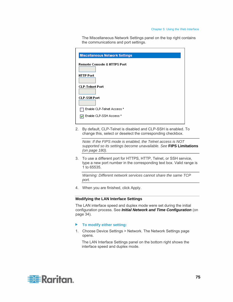
Chapter 5: Using the Web Interface
75
The Miscellaneous Network Settings panel on the top right contains the communications and port settings.
2. By default, CLP-Telnet is disabled and CLP-SSH is enabled. To change this, select or deselect the corresponding checkbox.
Note: If the FIPS mode is enabled, the Telnet access is NOT supported so its settings become unavailable. See FIPS Limitations (on page 180).
3. To use a different port for HTTPS, HTTP, Telnet, or SSH service, type a new port number in the corresponding text box. Valid range is 1 to 65535.
Warning: Different network services cannot share the same TCP port.
4. When you are finished, click Apply.
Modifying the LAN Interface Settings
The LAN interface speed and duplex mode were set during the initial configuration process. See Initial Network and Time Configuration (on page 34).
To modify either setting:
1. Choose Device Settings > Network. The Network Settings page opens.
The LAN Interface Settings panel on the bottom right shows the interface speed and duplex mode.

Chapter 5: Using the Web Interface
76
2. To change the LAN speed, select a different option in the LAN Interface Speed field.
Autodetect: System determines the optimum LAN speed through auto-negotiation.
10 Mbps: The LAN speed is always 10 Mbps.
100 Mbps: The LAN speed is always 100 Mbps.
3. To change the duplex mode, select a different option in the LAN Interface Duplex Mode field.
Autodetect: The PX selects the optimum transmission mode through auto-negotiation.
Half duplex: Data is transmitted in one direction (to or from the PX device) at a time.
Full duplex: Data is transmitted in both directions simultaneously.
4. When you are finished, click Apply.
Setting the Date and Time
Set the internal clock on the PX device manually, or link to a Network Time Protocol (NTP) server and let it set the date and time for the PX.
Important: If you are using Power IQ to manage the PX, you must configure Power IQ and the PX to have the same date/time or NTP settings.
To set the date and time:
1. Choose Device Settings > Date/Time. The Date/Time Settings page opens.
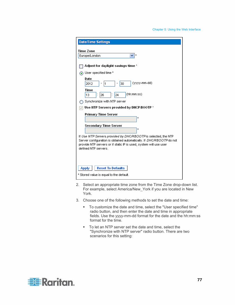
Chapter 5: Using the Web Interface
77
2. Select an appropriate time zone from the Time Zone drop-down list. For example, select America/New_York if you are located in New York.
3. Choose one of the following methods to set the date and time:
To customize the date and time, select the "User specified time" radio button, and then enter the date and time in appropriate fields. Use the yyyy-mm-dd format for the date and the hh:mm:ss format for the time.
To let an NTP server set the date and time, select the "Synchronize with NTP server" radio button. There are two scenarios for this setting:
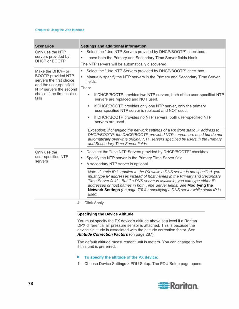
Chapter 5: Using the Web Interface
78
Scenarios Settings and additional information
Only use the NTP servers provided by DHCP or BOOTP
Select the "Use NTP Servers provided by DHCP/BOOTP" checkbox.
Leave both the Primary and Secondary Time Server fields blank.
The NTP servers will be automatically discovered.
Make the DHCP- or BOOTP-provided NTP servers the first choice, and the user-specified NTP servers the second choice if the first choice fails
Select the "Use NTP Servers provided by DHCP/BOOTP" checkbox.
Manually specify the NTP servers in the Primary and Secondary Time Server fields.
Then:
If DHCP/BOOTP provides two NTP servers, both of the user-specified NTP servers are replaced and NOT used.
If DHCP/BOOTP provides only one NTP server, only the primary user-specified NTP server is replaced and NOT used.
If DHCP/BOOTP provides no NTP servers, both user-specified NTP servers are used.
Exception: If changing the network settings of a PX from static IP address to DHCP/BOOTP, the DHCP/BOOTP-provided NTP servers are used but do not automatically overwrite original NTP servers specified by users in the Primary and Secondary Time Server fields.
Only use the user-specified NTP servers
Deselect the "Use NTP Servers provided by DHCP/BOOTP" checkbox.
Specify the NTP server in the Primary Time Server field.
A secondary NTP server is optional.
Note: If static IP is applied to the PX while a DNS server is not specified, you must type IP addresses instead of host names in the Primary and Secondary Time Server fields. But if a DNS server is available, you can type either IP addresses or host names in both Time Server fields. See Modifying the Network Settings (on page 73) for specifying a DNS server while static IP is used.
4. Click Apply.
Specifying the Device Altitude
You must specify the PX device's altitude above sea level if a Raritan DPX differential air pressure sensor is attached. This is because the device's altitude is associated with the altitude correction factor. See Altitude Correction Factors (on page 287).
The default altitude measurement unit is meters. You can change to feet if this unit is preferred.
To specify the altitude of the PX device:
1. Choose Device Settings > PDU Setup. The PDU Setup page opens.
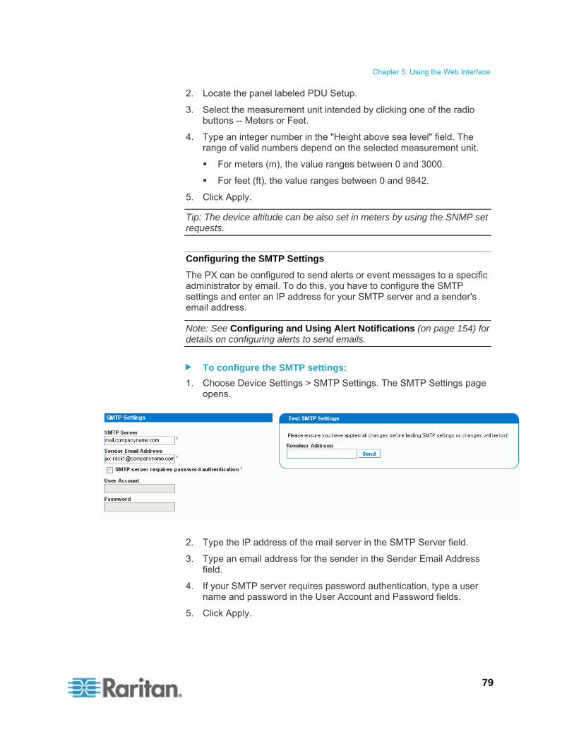
Chapter 5: Using the Web Interface
79
2. Locate the panel labeled PDU Setup.
3. Select the measurement unit intended by clicking one of the radio buttons -- Meters or Feet.
4. Type an integer number in the "Height above sea level" field. The range of valid numbers depend on the selected measurement unit.
For meters (m), the value ranges between 0 and 3000.
For feet (ft), the value ranges between 0 and 9842.
5. Click Apply.
Tip: The device altitude can be also set in meters by using the SNMP set requests.
Configuring the SMTP Settings
The PX can be configured to send alerts or event messages to a specific administrator by email. To do this, you have to configure the SMTP settings and enter an IP address for your SMTP server and a sender's email address.
Note: See Configuring and Using Alert Notifications (on page 154) for details on configuring alerts to send emails.
To configure the SMTP settings:
1. Choose Device Settings > SMTP Settings. The SMTP Settings page opens.
2. Type the IP address of the mail server in the SMTP Server field.
3. Type an email address for the sender in the Sender Email Address field.
4. If your SMTP server requires password authentication, type a user name and password in the User Account and Password fields.
5. Click Apply.

Chapter 5: Using the Web Interface
80
6. Now that you have set the SMTP settings, you can test it to ensure it works properly. To do this, type the receiver's email address in the Receiver Address field and click Send.
Note: Do not test the SMTP settings until you have first applied them. If you do, you will lose the settings and be forced to re-enter them.
Configuring the SNMP Settings
You can enable or disable SNMP communications between an SNMP manager and the PX.
Warning: If enabling SNMP v3, the PX only supports a maximum of 20 user profiles. See Creating a User Profile (on page 94).
To configure the SNMP communication:
1. Choose Device Settings > SNMP Settings. The SNMP Settings page opens.
2. Select the Enable SNMP Agent checkbox to enable communication with remote SNMP managers.

Chapter 5: Using the Web Interface
81
3. Select the Enable SNMP v1 / v2c Protocol checkbox to enable communication using SNMP v1 or v2c protocol.
Type the SNMP read-only community string in the Read Community field and the read/write community string in the Write Community field. Default community strings are "raritan_public" and "raritan_private" respectively.
Note: In the FIPS mode, SNMP v1 / v2c protocol is NOT supported so its settings become unavailable. See FIPS Limitations (on page 180).
4. Select the Enable SNMP v3 Protocol checkbox to enable communication using SNMP v3 protocol.
Additionally, select the Force Encryption checkbox to force using encrypted SNMP communication.
Note 1: In the FIPS mode, the Force Encryption checkbox is automatically selected when enabling the SNMP v3 protocol.
Note 2: To perform SNMP v3 operations successfully, make sure the name of your user group does NOT contain spaces.
5. Type the SNMP MIBII sysLocation value in the System Location field.
6. Type the SNMP MIBII sysContact value in the System Contact field.
7. Click on the "here" link at the bottom to download an SNMP MIB for your PX to use with your SNMP manager.
8. Click Apply.
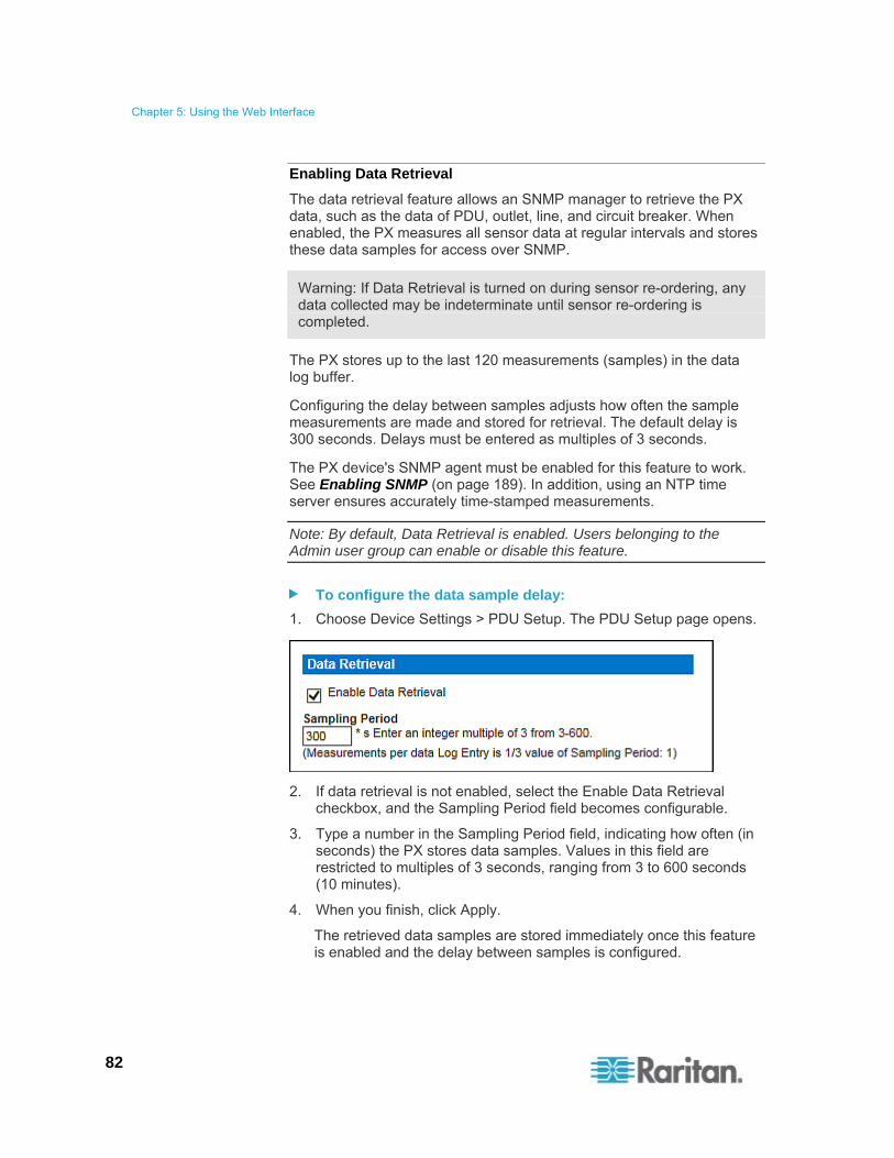
Chapter 5: Using the Web Interface
82
Enabling Data Retrieval
The data retrieval feature allows an SNMP manager to retrieve the PX data, such as the data of PDU, outlet, line, and circuit breaker. When enabled, the PX measures all sensor data at regular intervals and stores these data samples for access over SNMP.
Warning: If Data Retrieval is turned on during sensor re-ordering, any data collected may be indeterminate until sensor re-ordering is completed.
The PX stores up to the last 120 measurements (samples) in the data log buffer.
Configuring the delay between samples adjusts how often the sample measurements are made and stored for retrieval. The default delay is 300 seconds. Delays must be entered as multiples of 3 seconds.
The PX device's SNMP agent must be enabled for this feature to work. See Enabling SNMP (on page 189). In addition, using an NTP time server ensures accurately time-stamped measurements.
Note: By default, Data Retrieval is enabled. Users belonging to the Admin user group can enable or disable this feature.
To configure the data sample delay:
1. Choose Device Settings > PDU Setup. The PDU Setup page opens.
2. If data retrieval is not enabled, select the Enable Data Retrieval checkbox, and the Sampling Period field becomes configurable.
3. Type a number in the Sampling Period field, indicating how often (in seconds) the PX stores data samples. Values in this field are restricted to multiples of 3 seconds, ranging from 3 to 600 seconds (10 minutes).
4. When you finish, click Apply.
The retrieved data samples are stored immediately once this feature is enabled and the delay between samples is configured.
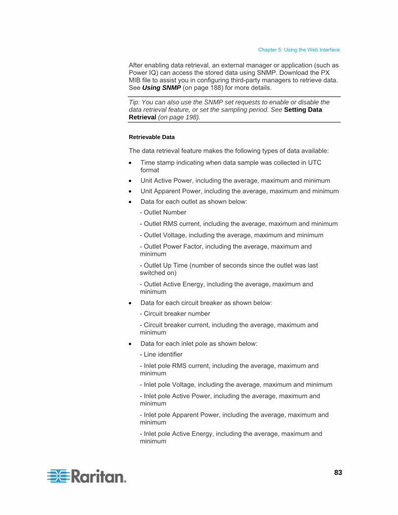
Chapter 5: Using the Web Interface
83
After enabling data retrieval, an external manager or application (such as Power IQ) can access the stored data using SNMP. Download the PX MIB file to assist you in configuring third-party managers to retrieve data. See Using SNMP (on page 188) for more details.
Tip: You can also use the SNMP set requests to enable or disable the data retrieval feature, or set the sampling period. See Setting Data Retrieval (on page 198).
Retrievable Data
The data retrieval feature makes the following types of data available:
Time stamp indicating when data sample was collected in UTC format
Unit Active Power, including the average, maximum and minimum
Unit Apparent Power, including the average, maximum and minimum
Data for each outlet as shown below:
- Outlet Number
- Outlet RMS current, including the average, maximum and minimum
- Outlet Voltage, including the average, maximum and minimum
- Outlet Power Factor, including the average, maximum and minimum
- Outlet Up Time (number of seconds since the outlet was last switched on)
- Outlet Active Energy, including the average, maximum and minimum
Data for each circuit breaker as shown below:
- Circuit breaker number
- Circuit breaker current, including the average, maximum and minimum
Data for each inlet pole as shown below:
- Line identifier
- Inlet pole RMS current, including the average, maximum and minimum
- Inlet pole Voltage, including the average, maximum and minimum
- Inlet pole Active Power, including the average, maximum and minimum
- Inlet pole Apparent Power, including the average, maximum and minimum
- Inlet pole Active Energy, including the average, maximum and minimum
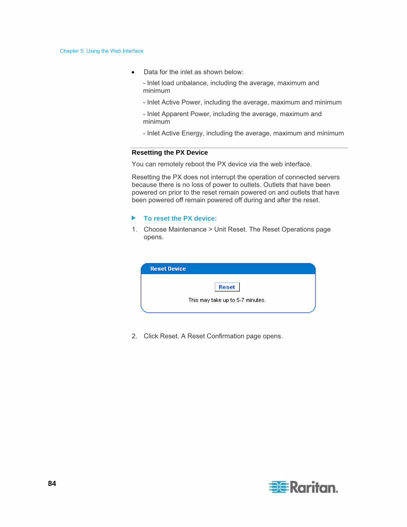
Chapter 5: Using the Web Interface
84
Data for the inlet as shown below:
- Inlet load unbalance, including the average, maximum and minimum
- Inlet Active Power, including the average, maximum and minimum
- Inlet Apparent Power, including the average, maximum and minimum
- Inlet Active Energy, including the average, maximum and minimum
Resetting the PX Device
You can remotely reboot the PX device via the web interface.
Resetting the PX does not interrupt the operation of connected servers because there is no loss of power to outlets. Outlets that have been powered on prior to the reset remain powered on and outlets that have been powered off remain powered off during and after the reset.
To reset the PX device:
1. Choose Maintenance > Unit Reset. The Reset Operations page opens.
2. Click Reset. A Reset Confirmation page opens.

Chapter 5: Using the Web Interface
85
3. To reboot the PX, click Really Reset. If you change your mind, click Cancel to terminate the reset operation. If you choose to proceed with the reset, the following page opens and the reset takes place. The reset takes several minutes to complete.
4. When the reset is complete, the Login page opens. Now you can log back in to the PX.
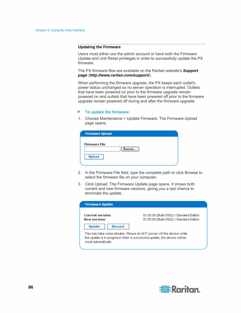
Chapter 5: Using the Web Interface
86
Updating the Firmware
Users must either use the admin account or have both the Firmware Update and Unit Reset privileges in order to successfully update the PX firmware.
The PX firmware files are available on the Raritan website's Support page (http://www.raritan.com/support/).
When performing the firmware upgrade, the PX keeps each outlet's power status unchanged so no server operation is interrupted. Outlets that have been powered on prior to the firmware upgrade remain powered on and outlets that have been powered off prior to the firmware upgrade remain powered off during and after the firmware upgrade.
To update the firmware:
1. Choose Maintenance > Update Firmware. The Firmware Upload page opens.
2. In the Firmware File field, type the complete path or click Browse to select the firmware file on your computer.
3. Click Upload. The Firmware Update page opens. It shows both current and new firmware versions, giving you a last chance to terminate the update.

Chapter 5: Using the Web Interface
87
Note: When upgrading a PX device over a low bandwidth network, after the firmware upload begins, do NOT switch the browser to another page before the upload is completed. This may take several minutes depending on the network speed.
4. To proceed with the update, click Update. To terminate the update, click Discard. The update may take 5 to 7 minutes and a message similar to the following appears.
If your PX is in the FIPS mode, it takes longer to finish upgrading the firmware, ranging between 7 to 10 minutes.
Note: Do NOT power off the PX during the update. To indicate at the rack that an update is in progress, the outlet LEDs flash and the device's three-digit LED display shows “FuP”.
5. When the update is complete, the PX resets, and the Login page re-opens. You can now log in and resume managing the PX.
Important: If you are using the PX with an SNMP manager, you should re-download the PX MIB after updating the firmware. This ensures your SNMP manager has the correct MIB for the release you are using. See Using SNMP (on page 188) for details.

Chapter 5: Using the Web Interface
88
PSoC Firmware Upgrade Failure
Raritan PX models described in this User Guide contain two types of processors:
The main PDU processor, which controls the PDU's high level functionality, such as the web server, SNMP agent, environmental sensor management and so on.
The PSoC (Programmable System On a Chip), which is responsible for low level outlet-related measurements, such as outlet current, voltage, power factor and so on.
Each PDU has one main PDU processor but can have one to six PSoC's depending on how many outlets it has.
The overall firmware upgrade process is controlled by the main PDU processor, which directs the upgrade of both its own firmware and the PSoC firmware. During the firmware upgrade, the main PDU processor first updates the PSoC's while it is still executing the old firmware. Though rare, if communication problems occur between the main PDU processor and a PSoC during the PSoC's firmware upgrade, that PSoC becomes temporarily inoperative, and a failure message is displayed at the end of the PSoC firmware upgrade. Once the main PDU processor completes its own firmware upgrade, the new PDU processor firmware will check and recover any inoperative PSoC's. When it fails to recover any inoperative PSoC, the failed PSoC as well as any impacted outlets are all reported in the Firmware Status field of the status panel.
The following status panel illustrates such a report.

Chapter 5: Using the Web Interface
89
In the Firmware Status report, the number prior to the square brackets refers to the inoperative PSoC. The range of numbers within the square brackets indicates the impacted outlets.
For example, "Failed PSOCs: 2[O:5-8] 4[O:13-16] 6[O:21-24]" means:
PSoC 2 firmware upgrade failed, and outlets 5 to 8 may not function properly since they are associated with PSoC 2
PSoC 4 firmware upgrade failed, and outlets 13 to 16 may not function properly since they are associated with PSoC 4
PSoC 6 firmware upgrade failed, and outlets 21 to 24 may not function properly since they are associated with PSoC 6
Full Disaster Recovery
If the firmware upgrade fails, causing the PX device to stop working, you can recover it by using a special utility rather than returning the device to Raritan. Contact Raritan Technical Support for the recovery utility.
An appropriate PX firmware file is required in the recovery procedure.

Chapter 5: Using the Web Interface
90
Copying Configurations with Bulk Configuration
The Bulk Configuration feature lets you save the settings of a configured PX device to your PC. You can use this configuration file to:
Copy this configuration to other PX devices of the same model and firmware version.
Restore the settings of the same PX device to this configuration.
Users saving PX configurations require the Bulk Configuration system permission. Users copying configurations require both the Bulk Configuration and the Unit Reset permissions.

Chapter 5: Using the Web Interface
91
Saving a PX Configuration
A source device is an already configured PX device that is used to create a configuration file containing the settings that can be shared between PX devices. These settings include user and group configurations, thresholds, alert policies, the access control list, and so on. This file does NOT contain device-specific information, including:
Device name
System name, system contact and system location
Network settings (IP address, gateway, netmask and so on)
Device logs
Outlet names
Outlet status
Environmental sensor names, mappings and thresholds
Environmental sensor alerts
Environmental sensor X, Y and Z location values
Outlet grouping data
Default outlet state (at either the Unit level or Outlet level)
Important: It is strongly recommended to assign a number to Telnet and SSH ports when saving the configuration. This is because a configuration file containing blank entries for Telnet and SSH ports restores the Telnet and SSH ports of the target PDUs to factory defaults.
The "default outlet state" setting is not saved in the configuration file to prevent the PDU from accidentally leaving outlets OFF at startup after the configuration is copied.
Note that the UTC time zone offset and NTP settings, if any, are saved though the "user-specified time" is not. Users should exercise caution when distributing a configuration file to the PX devices in a different time zone than the source device.
To save a configuration file:
1. Choose Maintenance > Bulk Configuration. The Bulk Configuration page opens.
2. Click Save Configuration. Your web browser then prompts you to save the file onto your PC.
Note: The bulk configuration file saves NTP synchronization time settings but does NOT save "user-specified" time settings. Therefore, you must re-configure the user-specified time after finishing the configuration copy.

Chapter 5: Using the Web Interface
92
Copying a PX Configuration
A target device is the PX device that loads another PX device's configuration file.
Copying a source PX device's configuration to a target PX device adjusts the target device's settings to match those of the source device.
In order to successfully copy a source device's configuration:
You must be one of the following users:
The Admin user
A normal user who belongs to the Admin user group
A normal user whose "IPMI Privilege Level" is set to No Access and "Bulk Configuration" is set to Yes
The target device must be running the same firmware version as the source device.
The target device must be of the same model type as the source device.
To copy a PX configuration:
1. Log in to the target device's web interface.
2. If the target device's firmware version does not match that of the source device, update the target's firmware. See Updating the Firmware (on page 86).
3. Choose Maintenance > Bulk Configuration. The Bulk Configuration page opens.
4. Under the Copy Configuration to Target area, click Browse and select the configuration file on your PC.
5. Click Copy Configuration.
Chapter 5: Using the Web Interface
93
Notes:
The bulk configuration file saves NTP synchronization time settings but does NOT save "user-specified" time settings. Therefore, you must re-configure the user-specified time after finishing the configuration copy.
All pre-existing "environmental sensor" alerts will be deleted after the copy operation is completed. See Creating Alerts (on page 161).
If configured, SNMP, SMTP and the local event log record the occurrence of a configuration copy on the target device, but NFS and Syslog servers do not.
If the source device is configured to "Force HTTPS for web access", and the target device is not, you may not be automatically redirected to the login page after the configuration copy is complete. In this case, simply refresh the web browser after the configuration copy is finished to make the login page appear.
Setting Up User Profiles
The PX is shipped with one built-in user profile: admin, which is used for initial login and configuration. This profile has full permissions, and should be reserved for the system administrator. This profile cannot be modified or deleted.
All users must have a user profile, which specifies a login name and password, and contains additional (optional) information about the user. It also assigns the user to a User Group, and the User Group determines the user's system and outlet permissions.
If you choose, you can refrain from assigning some or all users to a User Group, and instead assign their system and outlets permissions on an individual basis.
Note: By default, multiple users can log in simultaneously using the same login name. You can change this so only one user at a time can use a specific login name. This is done by choosing Device Settings > Security and selecting the Enable Single Login Limitation checkbox.

Chapter 5: Using the Web Interface
94
Creating a User Profile
Creating new users adds a new login to the PX. To create a new user, you must have both the User/Group Management privilege and an IPMI Privilege Level of OEM.
Warning: If enabling SNMP v3, the PX only supports a maximum of 20 user profiles. See Configuring the SNMP Settings (on page 80).
To create a user profile:
1. Choose User Management > Users & Groups. The User/Group Management page opens, divided into a User Management panel and a Group Management panel.

Chapter 5: Using the Web Interface
95
Note: Before entering any information in the user profile, make sure the User Group is created and available for selection. See Setting Up User Groups (on page 99).
2. In the User Management panel, type the following information about the user in the corresponding fields:
Field Type this data
New User Name The name the user enters to log in to the PX.

Chapter 5: Using the Web Interface
96
Field Type this data
Full Name The user's first and last names.
Password,
Confirm Password
The password the user enters to log in. Type it first in the Password field and then again in the Confirm Password field.
The password can be 4 to 32 characters long.
It is case sensitive.
Spaces are not permitted.
If the "Use Password as Encryption Phrase" checkbox is selected and SNMP v3 is used, the user password must be at least eight characters long.
SNMP v3 Encryption Phrase,
Confirm SNMP v3 Encryption Phrase
The password required when using secure SNMP v3 communication. When using SNMP v3, the encryption phrase must be at least eight characters long. See Using SNMP (on page 188).
To make the SNMP v3 encryption phrase different from the user password, deselect the "Use Password as Encryption Phrase" checkbox. Then type it first in the SNMP v3 Encryption Phrase field and again in the Confirm SNMP v3 Encryption Phrase field.
SNMP v3 authentication settings
The authentication algorithm applied for SNMP v3: MD5 or SHA_1.
In the FIPS mode, only SHA_1 is supported. See FIPS Limitations (on page 180).
SNMP v3 privacy settings
The privacy algorithm applied for SNMP v3: DES or AES_128.
In the FIPS mode, only AES_128 is supported. See FIPS Limitations (on page 180).
Email address An email address where the user can be reached.
Mobile Number A cell phone number where the user can be reached.
Note: New User Name, Password, and Confirm Password are mandatory fields.
3. Select a user group in the User Group field. The user group determines the system functions and outlets this user can access.
If you select None, the user is not assigned to a user group. Therefore, you must set the user's permissions individually. Before doing this, the user is blocked from accessing any system functions and outlets. See Setting User Permissions Individually (on page 98).
4. If you would like this user to set his or her own password, select the "Enforce user to change password on next login" checkbox. The user logs in using the password you entered above, and then is forced to change it to his or her choice.
5. Click Create. The user profile is created.
Chapter 5: Using the Web Interface
97
Copying a User Profile
You can create a new user profile with the same settings as an existing profile by using the copy function. Then modify the profile so that it differs as necessary from the original. This is a quick and easy way to create user profiles.
To copy a user profile:
1. Choose User Management > Users & Groups. The User/Group Management page opens.
2. Select the existing user profile in the Existing Users field.
3. Type the name of the new user profile in the New User Name field.
4. Click Copy. A new user profile is created with the same settings as the existing profile. The new profile can be seen by clicking the Existing Users field.
Modifying a User Profile
Users with User/Group Management permissions can modify user profiles. See Setting the System Permissions (on page 100) for details on setting user permissions.
To modify a user profile:
1. Choose User Management > Users & Groups. The User/Group Management page opens.
2. Select the user profile you want to modify from the Existing Users drop-down list. All information of the user profile is displayed except the password.
3. Make necessary changes to the information shown.
To change the password, type a new password in the Password and Confirm Password fields. If the password field is left blank, the password is not changed.
To change the SNMP v3 encryption phrase, type a new one in the SNMP v3 Encryption Phrase and Confirm SNMP v3 Encryption Phrase fields. If the encryption phrase field is left blank, the encryption phrase is not changed.
4. Click Modify.
Note: The name displayed in the "User (not in a group)" list of the User/Group System Permissions page remains unchanged even though you have modified the user name on the User/Group Management page. To make the user name assigned to the "None" User Group consistent on both pages, either leave the user name unchanged, or delete the user profile and then re-create it with a new name.

Chapter 5: Using the Web Interface
98
Deleting a User Profile
Remove a user profile when it is unnecessary.
To delete a user profile:
1. Choose User Management > Users & Groups. The User/Group Management page opens.
2. Select the user profile you want to delete in the Existing Users field.
3. Click Delete.
Setting User Permissions Individually
If you selected None as User Group when creating a user profile, you must set the user's permissions individually. Until you do this, the user is blocked from all system functions and outlets.
System Permissions
System permissions are the permissions to deal with system settings, including system date/time, network configuration, security settings, user management, and so on.
To set the system permissions:
1. Choose User Management > User/Group System Permissions. The User/Group System Permissions page opens. See Setting the System Permissions (on page 100).
2. Select the user from the "User (not in a group)" drop-down list. The list shows all user profiles that have NOT been assigned to a User Group.
3. Set the permissions as necessary. Click on each permission to select a permission level.
4. Click Apply.
Outlet Permissions
Outlet permissions determine whether a user can configure each outlet's settings or switch it (if applicable).
To set the outlet permissions:
1. Choose User Management > User/Group Outlet Permissions. The User/Group Outlet Permissions page opens. See Setting the Outlet Permissions (on page 102).
2. Select the user from the "User (not in a group)" drop-down list.
3. Select an appropriate permission level for each outlet.

Chapter 5: Using the Web Interface
99
4. Click Apply.
Note: A minimum IPMI privilege level "User" is required to switch outlets over IPMI, which causes no effect on front-end web use. The privilege level has no effect on outlet permissions.
Setting Up User Groups
The PX is shipped with one built-in user group: the Admin user group. This user group provides full system and outlet permissions. It can be neither modified nor deleted.
To restrict a user's permissions, create a user group with limited system and/or outlet permissions, and assign the user to that group.
Creating a User Group
It is better to create a user group with appropriate permissions before creating new user profiles that will have these permissions.
To create a user group:
1. Choose User Management > Users & Groups. The User/Group Management page opens, divided into a User Management panel and a Group Management panel.
2. In the Group Management panel, type the name of the new group in the New Group Name field.
Important: To perform SNMP v3 operations successfully, make sure the name of your user group does NOT contain spaces.
3. Click Create.

Chapter 5: Using the Web Interface
100
Setting the System Permissions
System permissions include all major functional areas of the web interface. When first creating a user group, all system permissions are disabled by default.
To set system permissions for a user group:
1. Choose User Management > User/Group System Permissions. The User/Group System Permissions page opens.
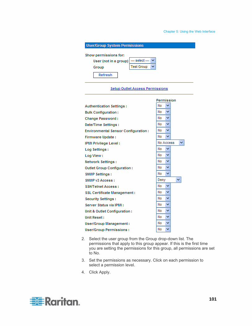
Chapter 5: Using the Web Interface
101
2. Select the user group from the Group drop-down list. The permissions that apply to this group appear. If this is the first time you are setting the permissions for this group, all permissions are set to No.
3. Set the permissions as necessary. Click on each permission to select a permission level.
4. Click Apply.

Chapter 5: Using the Web Interface
102
Note: The "User (not in a group)" field on this page is used to set individual user permissions. If you are setting group permissions, you may ignore this field. Some permissions must be enabled with other permissions for the effects to apply. Check the individual task descriptions in this guide for details.
Setting the Outlet Permissions
Setting outlet permissions allows you to specify which outlets all members of a user group are permitted to access. When first creating a user group, all outlet permissions are disabled by default.
To set outlet permissions for a user group:
1. Choose User Management > User/Group Outlet Permissions. The User/Group Outlet Permissions page opens.

Chapter 5: Using the Web Interface
103
2. Select the user group from the Group drop-down list. The outlet permissions that apply to this group appear. If this is the first time you are setting the outlet permissions for this group, all permissions are set to No.
3. Select an appropriate permission level for each outlet.
4. Click Apply.
Note: The "User (not in a group)" field on this page is used to set individual user permissions. If you are setting group permissions, you may ignore this field.
Copying a User Group
Copying is a quick and easy way to create user groups. You can first create a new user group with the same permissions as an existing user group by using the copy function. Then modify the group so that its permissions differ as necessary from the original.
All user groups can be copied except for the Admin and <Unknown> groups.
To copy a user group:
1. Choose User Management > Users & Groups. The User/Group Management page opens.
2. Select the existing user group from the Existing Groups field.
3. Type the name of the new user group in the New Group Name field.
4. Click Copy. A new user group is created with the same permissions as the existing group. The new user group can be seen by clicking the Existing Groups field.
Modifying a User Group
The only attribute that can be modified for a user group on the User/Group Management page is the group name.
To modify a user group's name:
1. Choose User Management > Users & Groups. The User/Group Management page opens.
2. Select the user group in the Existing Groups field. Its group name appears in the New Group Name field.
3. Modify the name.
Note: To perform SNMP v3 operations successfully, make sure the name of your user group does NOT contain spaces.
4. Click Modify.

Chapter 5: Using the Web Interface
104
Tip: To modify a user group's system or outlet permissions, repeat the procedure for setting the system or outlet permissions and make necessary changes. See Setting the System Permissions (on page 100) and Setting the Outlet Permissions (on page 102).
Deleting a User Group
Remove a user group when it is no longer needed.
To delete a user group:
1. Choose User Management > Users & Groups. The User/Group Management page opens.
2. Select the user group in the Existing Groups field.
3. Click Delete.
All members of this user group are automatically assigned to the "<Unknown>" group after the user group is deleted.
Setting Up and Managing Outlets
Global settings for all outlets can be configured at a time, such as the default outlet state and power cycling delay. Besides, with appropriate permissions, you should be able to access, set up, and switch an individual outlet.

Chapter 5: Using the Web Interface
105
Setting the Global Default Outlet State
The outlet state setting on the PDU Setup page determines the global default power state of ALL outlets when the PX device is powered on.
Note: Setting an individual outlet's startup state to something other than "Device default" overrides this global default state on that outlet. See Naming and Configuring Outlets (on page 109).
Users require the Unit & Outlet Configuration permission to view the PDU Setup page.
To set the default outlet state:
1. Choose Device Settings > PDU Setup. The PDU Setup page opens.

Chapter 5: Using the Web Interface
106
2. Select the desired outlet state from the "Default outlet state on device startup" drop-down list.
3. Click Apply.
Chapter 5: Using the Web Interface
107
Setting the Global Power Cycling Delay
When an outlet is power cycled, it is turned off and then back on. The power cycling delay setting on the PDU Setup page determines the length of time (in seconds) it takes for ALL outlets to turn back on after being shut down during the power cycle.
Users require the Unit & Outlet Configuration permission to view the PDU Setup page.
To set the power cycling and sequence delay for all outlets:
1. Choose Device Settings > PDU Setup. The PDU Setup page opens.
2. Type a number of seconds (s) in the PDU Power Cycling Delay field.
When power to the PX device is cycled either manually or because of a temporary power loss, this number determines how many seconds the PX waits before it provides power to the outlets. This is useful in cases where power may not initially be stable after being restored, or when UPS batteries may be charging. The delay value ranges from 0 to 3600 seconds (one hour).
3. Type a number of seconds (s) in the "Power off period during outlet power cycling" field.
When the outlets are power cycled, they are turned off and then back on. The number you enter here determines the length of time it takes for outlets to turn back on after turning off during the power cycle. The default is 10 seconds. The value ranges from 1 to 3600 seconds (one hour).
Tip: You can override this global setting of power off period for power cycling on individual outlets. See Naming and Configuring Outlets (on page 109). For instructions on power cycling an outlet from the Outlet Details page, see Power Cycling an Outlet (on page 111).
4. Type a number of milliseconds (ms) in the Sequence Delay field.
The outlet sequence delay determines the time interval the PX takes from outlet to outlet when powering ON or cycling all outlets. The default is 200 ms, which is sufficient to handle in-rush current conditions for most servers. Sequence delay ranges from 1 to 255000 ms.
For SAN (storage area network), disk arrays, and some other equipment, the delay may need to be extended.
5. Click Apply.
Tip: When there are a large number of outlets, set both the Power off period and the Sequence Delays to lower values. This way you can avoid a long wait before all outlets turn available again. This is especially useful when dealing with outlets grouped from other PX devices.

Chapter 5: Using the Web Interface
108
Setting the Outlet Power-On Sequence
By default, the outlets are sequentially powered on in the ascending order from outlet 1 to the highest-numbered outlet after turning ON or power cycling all outlets on the PX. You can change the power-on order of outlets. This is useful when there is a specific order in which the connected IT equipment should be powered up.
To set the outlet power-on sequence:
1. Choose Device Settings > PDU Setup. The PDU Setup page opens.
2. The current outlet power-on sequence appears in the list under Outlet Sequencing. To change the priority of an outlet, select it from the list and click one of the following buttons.
First: Moves the outlet to the top of the list, making it the first one to receive power.
Up: Moves the outlet up one position in the list.
Down: Moves the outlet down one position in the list.
Last: Moves the outlet to the bottom of the list, making it the final one to receive power.
3. Click Apply.
Note: If you use Outlet Grouping to group outlets together, you should adjust the Outlet Sequencing to ensure that all outlets from this PX that are part of an outlet group, power up consecutively.

Chapter 5: Using the Web Interface
109
Naming and Configuring Outlets
You can name an outlet to help you identify the IT equipment connected to it. Besides, you can set the default state, power off period during power cycling, and power on delay on a per-outlet basis on the Outlet Setup page.
Note: For instructions on configuring outlet thresholds and hysteresis, see Setting Outlet Thresholds and Hysteresis (on page 113).
To name and configure an outlet:
1. Choose Details > Outlet Setup. The Outlet Setup page opens.
2. Select the outlet in the "Show setup of outlet" field.
3. Type a name in the Outlet Name field.
It is a good idea to give the outlet a recognizable name according to the device connected to it. You can always change names if the device is replaced.
4. Select a default outlet state in the "Outlet state on device startup" field. This determines if the outlet is ON or OFF after the PX powers up.
If set to "Device default," this outlet follows the global default outlet state. See Setting the Global Default Outlet State (on page 105).
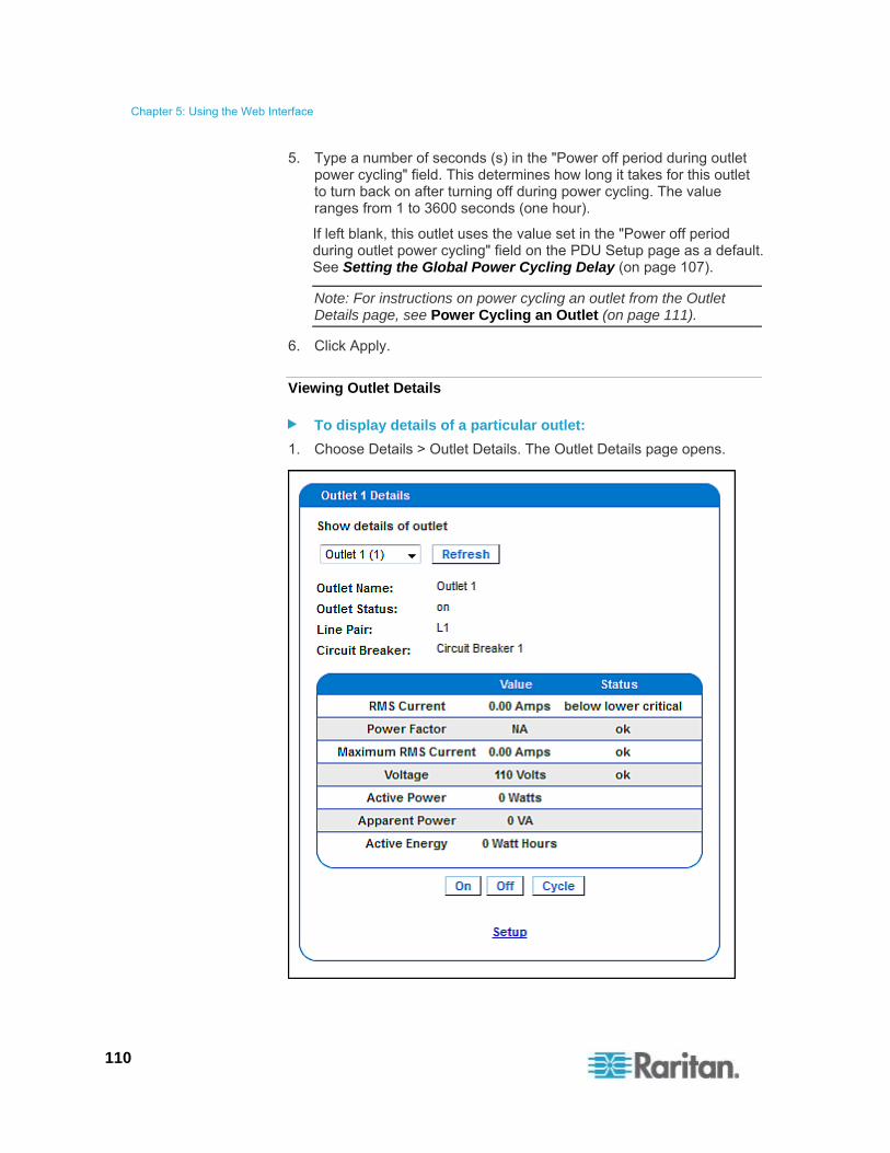
Chapter 5: Using the Web Interface
110
5. Type a number of seconds (s) in the "Power off period during outlet power cycling" field. This determines how long it takes for this outlet to turn back on after turning off during power cycling. The value ranges from 1 to 3600 seconds (one hour).
If left blank, this outlet uses the value set in the "Power off period during outlet power cycling" field on the PDU Setup page as a default. See Setting the Global Power Cycling Delay (on page 107).
Note: For instructions on power cycling an outlet from the Outlet Details page, see Power Cycling an Outlet (on page 111).
6. Click Apply.
Viewing Outlet Details
To display details of a particular outlet:
1. Choose Details > Outlet Details. The Outlet Details page opens.
Chapter 5: Using the Web Interface
111
2. Select an outlet in the "Show details of outlet" field. The page shows these details about this outlet:
Outlet name
Outlet status
Line Pair (if applicable)
Circuit Breaker (if applicable)
Readings, including:
- RMS current
- Power Factor
- Maximum RMS Current
- Voltage
- Active Power
- Apparent Power
- Active Energy (energy consumption, if applicable on your model)
Note: To go to the Outlet Setup page, click the Setup link at the bottom. See Naming and Configuring Outlets (on page 109).
Power Cycling an Outlet
Power cycling an outlet turns an outlet OFF and then ON again. This function works only for outlets that are in the ON state.
To power cycle an outlet:
1. Choose Details > Outlet Details. The Outlet Details page opens.
2. Select an outlet in the "Show details of outlet" field. Make sure the outlet is ON.
3. Click Cycle.
Tip: You can also power cycle an outlet from the Home page. See Turning On or Off an Outlet, or Cycling the Power (on page 66).
Note: The length of time between the off and on states in a power cycle can be set on the PDU level and the outlet level. See Setting the Global Power Cycling Delay (on page 107) and Naming and Configuring Outlets (on page 109).

Chapter 5: Using the Web Interface
112
Turning an Outlet On or Off
This section describes how to turn on or off an outlet from the Outlet Details page.
Tip: To switch an outlet from the Home page, see Turning On or Off an Outlet, or Cycling the Power (on page 66).
To turn an outlet on or off:
1. Choose Details > Outlet Details. The Outlet Details page opens.
2. Select an outlet in the "Show details of outlet" field.
3. Click On to turn the outlet ON. Click Off to turn the outlet OFF.
Note: On a three-phase "delta" model, it is likely an overcurrent warning message appears when you try to turn on an outlet. For details, see Current Warning on a Three-Phase Delta Model (on page 68).
Setting Up Power Thresholds and Hysteresis
The PX is shipped with certain PDU and outlet power thresholds already defined, and with a hysteresis value already set for all thresholds. You can change the default thresholds and hysteresis values.
To understand how the hysteresis works, see A Note about Untriggered Alerts (on page 166).
Note: When setting the thresholds, remember that you can set up alerts that are triggered whenever any thresholds are crossed. See Configuring and Using Alert Notifications (on page 154).
Setting PDU Thresholds and Hysteresis
Users require the Unit & Outlet Configuration permission to view the PDU Setup page.
Both the Unit & Outlet Configuration and the Line & Circuit Breaker Configuration permissions are required to adjust thresholds and hysteresis on the PDU Setup page.
To set the PX thresholds and hysteresis:
1. Choose Device Settings > PDU Setup. The PDU Setup page opens.
2. Set the voltage, line current, temperature, and (if applicable) circuit breaker current thresholds for the PDU in the Thresholds panel. Enter critical or non-critical threshold for each item.
For the PDU's temperature thresholds, only positive numbers or zero are accepted so do NOT enter negative numbers.

Chapter 5: Using the Web Interface
113
Note: If you are using a PX in-line monitor, only the temperature threshold and hysteresis for the PDU are available on the PDU Setup page.
3. If necessary, change the hysteresis values for voltage, line current, temperature and (if applicable) circuit breaker current in the Thresholds panel. See What is Threshold Hysteresis? (on page 167) for the definition of the hysteresis.
To disable the hysteresis, type 0 (zero).
To enable the hysteresis, type a non-zero value, which must meet the rules described in the table:
Threshold Criterion
Upper critical threshold Larger than or equal to the following formula:
upper non-critical threshold + hysteresis
Upper non-critical threshold Larger than or equal to the following formula:
lower non-critical threshold + (2 x hysteresis)
Lower non-critical threshold Larger than or equal to the following formula:
lower critical threshold + hysteresis
4. Click Apply.
Setting Outlet Thresholds and Hysteresis
You can set the thresholds for outlet RMS current, and by default, the PX assigns a hysteresis value for the outlet threshold.
Note: If you are using a PX in-line monitor, the outlet voltage threshold and hysteresis are also available on the same page.
To set the current thresholds and hysteresis of an outlet:
1. Choose Details > Outlet Setup. The Outlet Setup page opens.
2. Select an outlet in the "Show setup of outlet" field.
3. Set the RMS current threshold for the outlet in the Thresholds panel.
Ensure the value you enter for the upper critical threshold is NOT larger than the maximum current ratings of the outlet.
4. Adjust the hysteresis setting for the outlet threshold if necessary. See What is Threshold Hysteresis? (on page 167) for the definition of the hysteresis.
To disable the hysteresis, type 0 (zero).

Chapter 5: Using the Web Interface
114
To enable the hysteresis, type a non-zero value, which must meet the rules described in the table:
Threshold Criterion
Upper critical threshold Larger than or equal to the following formula:
upper non-critical threshold + hysteresis
Upper non-critical threshold Larger than or equal to the following formula:
lower non-critical threshold + (2 x hysteresis)
Lower non-critical threshold Larger than or equal to the following formula:
lower critical threshold + hysteresis
5. Click Apply.
Exception: For any 5A-rated outlet, default threshold values do NOT follow the above rules. Default upper and lower thresholds are within the default hysteresis limit of one another, which results in error messages when resetting or configuring the outlet thresholds. Therefore, it is strongly recommended to change the default hysteresis to 0.5A or less when configuring outlet thresholds for 5A-rated outlets.
Monitoring Line and Circuit Breaker Status
The PX provides details for additional information on Line and Circuit Breaker status.

Chapter 5: Using the Web Interface
115
Monitoring Unbalanced Loads
In a three-phase PX device, a load imbalance occurs when the current on a line differs from the average current of all three lines. The largest absolute difference in current is expressed as a percentage of the average current. This value is the unbalanced load percentage. See Unbalanced Load Calculation (on page 285).
An unbalanced load indicates that more current is being drawn from one line than it is from the others. The larger the percentage is, the greater the difference. Reducing this imbalance maximizes the power available for use.
Enabling Unbalanced Load Detection displays the unbalanced loads percentage below the three individual Line graphs. This Unbalanced Load indicator is color coded:
White indicates the imbalance is below the non-critical threshold.
Yellow indicates the imbalance is above the non-critical threshold.
Red indicates the imbalance is above the critical threshold.
Enabling Unbalanced Load Detection
To monitor unbalanced loads, you must enable unbalanced load detection.
To enable unbalanced load detection:
1. Choose Device Settings > PDU Setup. The PDU Setup page opens.
2. Select the Enable Unbalanced Load Detection checkbox.
3. Click Apply.
You can configure non-critical and critical thresholds for the percentage of imbalance. This allows you to use the Alerts and Notification system as another means to react to load imbalance events.

Chapter 5: Using the Web Interface
116
Configuring Unbalanced Load Thresholds
Configuring these thresholds determines when the Unbalanced Load indicator changes colors from white to yellow or red. It also configures the unbalanced load event thresholds used in Alert Notifications.
Unbalanced Load Detection must be enabled before these thresholds take effect.
To configure unbalanced load thresholds:
1. Choose Device Settings > PDU Setup. The PDU Setup page opens.
2. Set the Unbalanced Load percentage for the Upper Non-Critical threshold and the Upper Critical threshold.
The difference between Critical and Non-Critical thresholds must be at least 2 percent regardless of the hysteresis value, and both thresholds must not exceed 100.
For example:
If Upper Critical = 100, then Upper Non-Critical = 98 (100-2) or lower
If Upper Critical = 99, then Upper Non-Critical = 97 (99-2) or lower
3. If necessary, change the hysteresis. See What is Threshold Hysteresis? (on page 167) for the definition of the hysteresis.
4. Click Apply.
Balancing Loads
Balancing the current draw on your lines maximizes the power usage before a circuit breaker is tripped. To keep line loads as balanced as possible, move servers and other equipment from over-utilized lines to under-utilized ones.
This involves the following:
1. Check what outlets receive power from the over-utilized line.
2. Disconnect a server from those outlets.
3. Connect the server to an outlet receiving power from the under-utilized line.

Chapter 5: Using the Web Interface
117
Line Details Page
To open the Line Details page, choose Details > Line Details.
The page opens and displays the following:
RMS Current: The present current draw per line.
RMS Max Current: The largest amount of current drawn per line since the PX device's last boot.
Current Remaining: The amount of available current that can be drawn per line.
In addition, the PDU voltage is displayed on this page.

Chapter 5: Using the Web Interface
118
Circuit Breaker Details Page
To view the Circuit Breaker details, choose Details > CB Details.
Each bank of outlets governed by a circuit breaker is listed as a table, and indicates what lines they draw power from. Each table contains the status of the circuit breaker, present current draw through that bank, the largest amount of current that was drawn by that bank since the PX device last booted, and the amount of available current that the circuit breaker can handle.
Access Security Control
The PX provides tools to control access. You can enable the internal firewall, create firewall rules, and create login limitations.
In addition, you can disable the PDU's response to any ping request to further enhance the security.

Chapter 5: Using the Web Interface
119
Forcing HTTPS Encryption
HTTPS uses Secure Sockets Layer (SSL) technology to encrypt all traffic to and from the PX device so it is a more secure protocol than HTTP.
You can force users to access the PX web interface through the HTTPS protocol only. By default, this protocol is enabled so you need to enable it only when it is disabled.
To force HTTPS access to the PX web interface:
1. Choose Device Settings > Security. The Security Settings page opens. Locate the HTTP Encryption panel at the upper left corner.
2. Select the "Force HTTPS for web access" checkbox.
Note: In the FIPS mode, HTTPS access is automatically enabled so the HTTPS checkbox is replaced by the message "HTTPS for web access enabled in FIPS mode."
3. Click Apply. HTTPS is now required for access.
After enabling the HTTPS protocol, all access attempts using HTTP are redirected to HTTPS automatically.
Configuring the Firewall
The PX has a firewall that you can configure to prevent specific IP addresses from accessing the PX device. When the PX was initially configured, you were prompted to enable or disable IP access control. If you selected Disable (the default), the firewall was not enabled.
To configure the firewall:
1. Enable the firewall. See Enabling the Firewall (on page 120).
2. Set the default policy. See Changing the Default Policy (on page 120).
3. Create firewall rules specifying which addresses to accept and which ones to discard. See Creating Firewall Rules (on page 121).
Changes made to firewall rules take effect immediately. Any unauthorized IP activities cease instantly.
Note: The purpose of disabling the firewall by default is to prevent users from accidentally locking themselves out of the device. See Initial Network and Time Configuration (on page 34).

Chapter 5: Using the Web Interface
120
Enabling the Firewall
The firewall rules, if any, take effect only after the firewall is enabled.
To enable the PX firewall:
1. Choose Device Settings > Security. The Security Settings page opens. Locate the panel labeled IP Access Control.
2. Select the Enable IP Access Control checkbox. This enables the firewall.
3. Click Apply.
Changing the Default Policy
After enabling the firewall, the default policy is to accept traffic from all IP addresses. This means only IP addresses discarded by a specific rule will NOT be permitted to access the PX.
You can change the default policy to DROP, in which case traffic from all IP addresses is dropped except the IP addresses accepted by a specific rule.
To change the default policy:
1. Choose Device Settings > Security. The Security Settings page opens. Locate the panel labeled IP Access Control.
2. Ensure the Enable IP Access Control checkbox is selected.
3. The default policy is shown in the Default Policy field. To change it, select a different policy.
4. Click Apply to apply the new policy.

Chapter 5: Using the Web Interface
121
Creating Firewall Rules
Firewall rules determine whether to accept or discard traffic intended for the PX, based on the IP address of the host sending the traffic. When creating firewall rules, keep these principles in mind:
Rule order is important.
When traffic reaches the PX device, the rules are executed in numerical order. Only the first rule that matches the IP address determines whether the traffic is accepted or discarded. Any subsequent rules matching the IP address are ignored by the PX.
Subnet mask is required.
When typing the IP address, you must specify BOTH the address and a subnet mask. For example, to specify a single address in a Class C network, use this format:
x.x.x.x/24
where /24 = a subnet mask of 255.255.255.0.
To specify an entire subnet or range of addresses, change the subnet mask accordingly.
Note: Valid IPv4 addresses range from 0.0.0.0 through 255.255.255.255. Make sure the IPv4 addresses entered are within the scope.
To create firewall rules:
1. Choose Device Settings > Security. The Security Settings page opens. Locate the panel labeled IP Access Control.
2. Ensure the Enable IP Access Control checkbox is selected.
3. Create specific rules. See the table for different operations.
Action Do this...
Add a rule to the end of the rules list
Type an IP address and subnet mask in the IP/Mask field.
Select ACCEPT or DROP in the Policy field.
Click Append.
Do NOT enter a rule number. The system automatically numbers the rule.

Chapter 5: Using the Web Interface
122
Action Do this...
Insert a rule between two existing rules
Type a rule number above which you want to insert a new rule in the "Rule #" field. For example, to insert a rule between rules #3 and #4, type 4.
Type an IP address and subnet mask in the IP/Mask field.
Select ACCEPT or DROP in the Policy field.
Click Insert.
The system inserts the rule and automatically renumbers the following rules.
Replace an existing rule Type the number of the rule to replace in the "Rule #" field.
Type an IP address and subnet mask in the IP/Mask field.
Select ACCEPT or DROP in the Policy field.
Click Replace.
This system replaces the existing rule with the one you just created.
4. When finished, the rules appear in the IP Access Control panel.
5. Click Apply. The rules are applied.

Chapter 5: Using the Web Interface
123
Deleting Firewall Rules
When any firewall rules become obsolete or unnecessary, remove them.
To delete a firewall rule:
1. Choose Device Settings > Security. The Security Settings page opens. Locate the panel labeled IP Access Control.
2. Ensure the Enable IP Access Control checkbox is selected.
3. Type the rule number in the "Rule #" field.
4. Click Delete to remove it from the rule list.
5. Click Apply to save the changes.
Creating Group Based Access Control Rules
Group based access control rules are similar to firewall rules, except they are applied to members of specific user groups. This enables you to give entire user groups system and outlet permissions, based on their IP addresses.
To create group based access control rules:
1. Enable the feature. See Enabling the Feature (on page 124).
2. Set the default action. See Changing the Default Action (on page 124).
3. Create rules that accept or drop traffic sending from specific addresses when they are associated with a specific user group. See Creating Group Based Access Control Rules (on page 125).
Changes made do not affect users currently logged in until the next login.
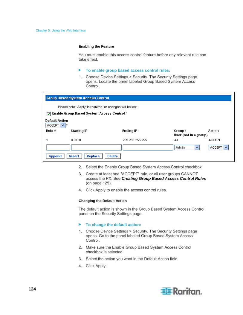
Chapter 5: Using the Web Interface
124
Enabling the Feature
You must enable this access control feature before any relevant rule can take effect.
To enable group based access control rules:
1. Choose Device Settings > Security. The Security Settings page opens. Locate the panel labeled Group Based System Access Control.
2. Select the Enable Group Based System Access Control checkbox.
3. Create at least one "ACCEPT" rule, or all user groups CANNOT access the PX. See Creating Group Based Access Control Rules (on page 125).
4. Click Apply to enable the access control rules.
Changing the Default Action
The default action is shown in the Group Based System Access Control panel on the Security Settings page.
To change the default action:
1. Choose Device Settings > Security. The Security Settings page opens. Go to the panel labeled Group Based System Access Control.
2. Make sure the Enable Group Based System Access Control checkbox is selected.
3. Select the action you want in the Default Action field.
4. Click Apply.
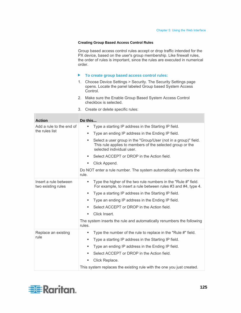
Chapter 5: Using the Web Interface
125
Creating Group Based Access Control Rules
Group based access control rules accept or drop traffic intended for the PX device, based on the user's group membership. Like firewall rules, the order of rules is important, since the rules are executed in numerical order.
To create group based access control rules:
1. Choose Device Settings > Security. The Security Settings page opens. Locate the panel labeled Group based System Access Control.
2. Make sure the Enable Group Based System Access Control checkbox is selected.
3. Create or delete specific rules:
Action Do this...
Add a rule to the end of the rules list
Type a starting IP address in the Starting IP field.
Type an ending IP address in the Ending IP field.
Select a user group in the "Group/User (not in a group)" field. This rule applies to members of the selected group or the selected individual user.
Select ACCEPT or DROP in the Action field.
Click Append.
Do NOT enter a rule number. The system automatically numbers the rule.
Insert a rule between two existing rules
Type the higher of the two rule numbers in the "Rule #" field. For example, to insert a rule between rules #3 and #4, type 4.
Type a starting IP address in the Starting IP field.
Type an ending IP address in the Ending IP field.
Select ACCEPT or DROP in the Action field.
Click Insert.
The system inserts the rule and automatically renumbers the following rules.
Replace an existing rule
Type the number of the rule to replace in the "Rule #" field.
Type a starting IP address in the Starting IP field.
Type an ending IP address in the Ending IP field.
Select ACCEPT or DROP in the Action field.
Click Replace.
This system replaces the existing rule with the one you just created.

Chapter 5: Using the Web Interface
126
4. Click Apply to apply the rules.
Deleting Group Based Access Control Rules
When any access control rule becomes unnecessary or obsolete, remove it.
To delete a group based access control rule:
1. Choose Device Settings > Security. The Security Settings page opens. Locate the panel labeled Group Based System Access Control.
2. Make sure the Enable Group Based System Access Control checkbox is selected.
3. Type the rule number in the "Rule #" field.
4. Click Delete. The rule is removed from the rule list.
5. Click Apply to save the changes.
Setting Up User Login Controls
You can set up login controls to make it more difficult for hackers to access the PX and the equipment connected to it. You can arrange to lock persons out after a specified number of failed logins, limit the number of persons who log in using the same user name at the same time, and force users to create strong passwords.
Enabling User Blocking
User blocking determines how many times a user can attempt to log in to the PX and fail authentication before the user is blocked.
To enable user blocking:
1. Choose Device Settings > Security. The Security Settings page opens. Go to the User Blocking panel.
2. Type a number in the "Maximum number of failed logins" field. This is the maximum number of failed logins the user is permitted before being blocked from accessing the PX device.

Chapter 5: Using the Web Interface
127
If no number is entered, there is no limit on failed logins.
3. Type a number in the Block Time field. This is the length of time in minutes the login is blocked.
If no number is entered, there is no time limit on blocking the login.
4. Click Apply.
Enabling Login Limitations
Login limitations determine whether more than one person can use the same login name simultaneously, and whether users are required to change passwords at regular intervals.
To enable login limitations:
1. Choose Device Settings > Security. The Security Settings page opens. Go to the Login Limitations panel.
2. To prevent multiple persons from using the same login name at the same time, select the Enable Single Login Limitation checkbox.
3. To force users to change their passwords regularly, select the Enable Password Aging checkbox, and then enter a number of days in the "Password Aging Interval (days)" field. Users are required to change their password every time that number of days has passed.
4. To adjust how long users can remain idle before they are forcibly logged out, enter a time in minutes in the "Idle Timeout (minutes)" field. The default value is 15 minutes.
5. Click Apply.
Tip: Keep the idle timeout to 15 minutes or less if possible. This reduces the number of idle sessions connected, and the number of simultaneous commands sent to the PX.

Chapter 5: Using the Web Interface
128
Enabling Strong Passwords
Use of strong passwords makes it more difficult for intruders to crack user passwords and access the PX. By default, strong passwords should be at least eight characters long, and contain upper- and lower-case letters, numbers, and special characters, such as @ or &.
To force users to create strong passwords:
1. Choose Device Settings > Security. The Security Settings page opens. The Strong Passwords panel appears at the bottom of the page.
2. Select the Enable Strong Passwords checkbox to activate the strong password feature. The following are the default settings:
Minimum length = 8 characters
Maximum length = 16 characters
At least one lowercase character = Required
At least one uppercase character = Required
At least one numeric character = Required
At least one printable special character = Required
Number of restricted passwords = 5
Note: The maximum password length accepted by the PX is 32 characters.

Chapter 5: Using the Web Interface
129
3. Make necessary changes to default settings.
4. Click Apply. The changes are applied.
Disabling the PDU's Ping Response
The PX responds to the ICMP ping request by default. You can have the PDU stop responding to such requests if necessary.
To disable the PDU's response to ping:
1. Choose Device Settings > Security. The Security Settings page opens. Go to the panel labeled Ping (ICMP Echo Request) Settings.
2. Deselect the "Ping enabled" checkbox.
3. Click Apply.
Setting Up a Digital Certificate
Having an X.509 digital certificate ensures that both parties in an SSL connection are who they say they are.
To obtain a certificate for the PX, create a Certificate Signing Request (CSR) and submit it to a certificate authority (CA). After the CA processes the information in the CSR, it provides you with a certificate, which you must install on the PX.
Note 1: If you are using an SSL certificate that is part of a certificate chain, each part of the chain is signed during the validation process.
Note 2: See Forcing HTTPS Encryption (on page 119) for instructions on forcing users to employ SSL when connecting to the PX.

Chapter 5: Using the Web Interface
130
Creating a Certificate Signing Request
Follow this procedure to create the CSR for your PX.
To create a CSR:
1. Choose Device Setting > Certificate. The first page of the SSL Server Certificate Management page appears.
2. Provide the information requested.
Field Type this...
Common Name The fully qualified domain name (FQDN) of your PX.
Organizational Unit The name of your department.
Organization The registered name of your company.
Locality/City The city where your company is located.
State/Province The full name of the state or province where your company is located.
Country (ISO Code) The country where your company is located. Use the standard ISO
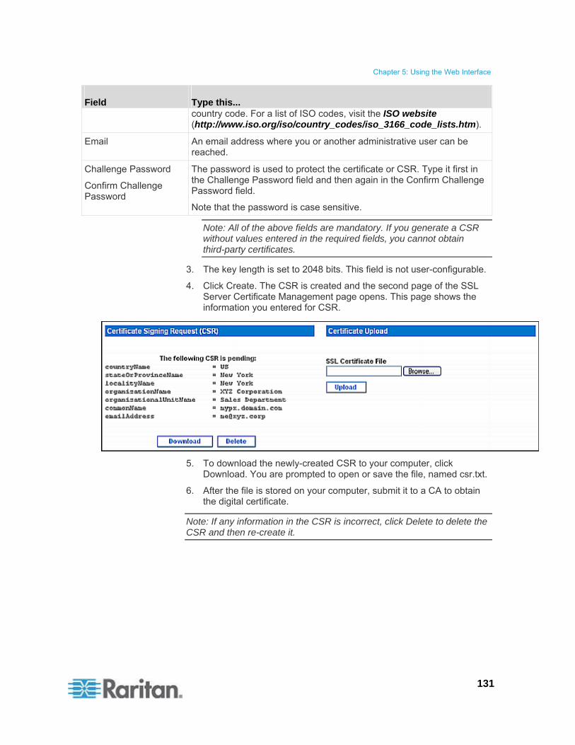
Chapter 5: Using the Web Interface
131
Field Type this... country code. For a list of ISO codes, visit the ISO website (http://www.iso.org/iso/country_codes/iso_3166_code_lists.htm).
Email An email address where you or another administrative user can be reached.
Challenge Password
Confirm Challenge Password
The password is used to protect the certificate or CSR. Type it first in the Challenge Password field and then again in the Confirm Challenge Password field.
Note that the password is case sensitive.
Note: All of the above fields are mandatory. If you generate a CSR without values entered in the required fields, you cannot obtain third-party certificates.
3. The key length is set to 2048 bits. This field is not user-configurable.
4. Click Create. The CSR is created and the second page of the SSL Server Certificate Management page opens. This page shows the information you entered for CSR.
5. To download the newly-created CSR to your computer, click Download. You are prompted to open or save the file, named csr.txt.
6. After the file is stored on your computer, submit it to a CA to obtain the digital certificate.
Note: If any information in the CSR is incorrect, click Delete to delete the CSR and then re-create it.
Chapter 5: Using the Web Interface
132
Installing a Certificate
After the CA provides a signed certificate according to the CSR you submitted, you must install it on the PX.
To upload an SSL certificate, you must log in as the administrator (admin).
To install the certificate:
1. Choose Device Settings > Certificate. The second page of the Server Certificate Management page opens.
2. In the SSL Certificate File field, type or click Browse to navigate to the certificate file.
3. Click Upload. The certificate is installed on the PX.

Chapter 5: Using the Web Interface
133
Setting Up External Authentication
For security purposes, users attempting to log in to the PX must be authenticated. The PX supports one of the following authentication mechanisms:
Local database of user profiles on the PX
Lightweight Directory Access Protocol (LDAP)
Remote Access Dial-In User Service (RADIUS) protocol
Exception: In the FIPS mode, RADIUS authentication is NOT supported, and LDAP authentication can be supported only when the SSL encryption is enabled. See FIPS Limitations (on page 180).
By default, the PX is configured for local authentication. If you stay with this method, you do not need to do anything other than create user profiles for each authorized user. If you prefer to use an external LDAP or RADIUS server, you must:
Provide the PX with the information about the server.
Create user profiles for users who are authenticated externally because a user profile determines the User Group to which the user belongs, and determines the system and outlet permissions for the user accordingly.
When users log in with external authentication, even though they are authorized to perform outlet operations, they cannot perform operations on Outlet Groups. Only local users can perform operations on Outlet Groups so users must authenticate locally to do this.
Note: Setting the LDAP user attribute rciusergroup to admin allows an Active Directory® user to log in to the PX with Administrator privileges. This occurs even if the user is assigned to the Unknown user group that normally has no access permissions.
When configured for external authentication, all PX users must have an account on the external authentication server. Local-authentication-only users will have no access to the PX except for the admin, who always can access the PX.

Chapter 5: Using the Web Interface
134
Gathering Information for LDAP Configuration
It requires knowledge of your LDAP server and directory settings to configure the PX for LDAP authentication. If you are not familiar with the settings, consult your LDAP administrator for help.
To configure LDAP authentication, you need to check:
The IP address or hostname of the LDAP server
The IP address of a backup or secondary LDAP server (optional)
Whether the Secure LDAP protocol (LDAP over SSL) is being used
If Secure LDAP is in use, consult your LDAP administrator for the CA certificate file.
The network port used by the LDAP server
The type of the LDAP server, usually one of the following options:
A generic LDAP server
Novell Directory Service
Microsoft Active Directory® (AD)
If using a Microsoft Active Directory server, consult your AD administrator for the name of the Active Directory Domain.
Bind Distinguished Name (DN) and password (if anonymous bind is NOT used)
The Base DN of the server (used for searching for users)
The login name attribute (or AuthorizationString)
The user entry object class
The user search subfilter (or BaseSearch)

Chapter 5: Using the Web Interface
135
Setting Up LDAP Authentication
The PX supports both LDAP and LDAPS authentication only when the FIPS mode is disabled. In the FIPS mode, only LDAPS authentication works properly so all LDAP connections must be made over SSL. See FIPS Limitations (on page 180).
To set up LDAP authentication:
1. Choose Device Settings > Authentication. The Authentication Settings page opens.

Chapter 5: Using the Web Interface
136
2. Select the LDAP radio button.
3. Type of external LDAP/LDAPS server. Choose from among the options available:
Chapter 5: Using the Web Interface
137
Generic LDAP Server.
Novell Directory
Microsoft Active Directory. Active Directory is an implementation of LDAP/LDAPS directory services by Microsoft for use in Windows environments.
4. User LDAP Server - Type the IP address or DNS name of your LDAP/LDAPS server (up to 37 characters).
When the SSL Enabled checkbox is selected, the DNS name (fully qualified domain name) must be used.
Important: You must specify one LDAP/LDAPS server in this field for the PX to perform remote authentication.
5. Backup User LDAP Server - Type the IP address or DNS name of your backup LDAP/LDAPS server (up to 37 characters).
When the SSL Enabled checkbox is selected, the DNS name (fully qualified domain name) must be used. Note that the remaining fields share the same settings with the User LDAP Server field. Optional
6. SSL Enabled - Select this checkbox if you would like to use SSL. Secure Sockets Layer (SSL) is a cryptographic protocol that allows the PX to communicate securely with the LDAP/LDAPS server.
Note: In the FIPS mode, only LDAPS authentication is supported so you must enable the SSL.
7. Port - The default Port is 389. Either use the standard LDAP TCP port or specify another port.
8. SSL Port - The default is 636. Either use the default port or specify another port. This field is enabled when the SSL Enabled checkbox is selected.
9. Certificate File - Consult your authentication server administrator to get the CA certificate file in Base64 encoded X-509 format for the LDAP/LDAPS server. Click Browse to navigate to the certificate file. This field is enabled when the SSL Enabled checkbox is selected.
10. Anonymous bind - For "Generic LDAP Server" or "Novell Directory Service," use this checkbox to enable or disable anonymous bind.
To use anonymous bind, select this checkbox. By default it is selected.
When a Bind DN and password are required to bind to the external LDAP/LDAPS server, deselect this checkbox.
11. Bind with credentials - For "Microsoft Active Directory," use this checkbox to enable or disable anonymous bind.
To use anonymous bind, deselect this checkbox. This is the default.

Chapter 5: Using the Web Interface
138
When a Bind DN and password are required to bind to the external LDAP/LDAPS server, select this checkbox.
12. "Bind DN" and "Password" - Type the Bind DN and password when Bind DN and password are required.
13. Base DN of user LDAP server - Enter the name you want to bind against the LDAP/LDAPS server (up to 255 characters), and where in the database to begin searching for the specified Base DN.
An example Base Search value might be: cn=Users,dc=raritan,dc=com. Consult your authentication server administrator for appropriate values to enter into these fields.
14. Type the following information in the corresponding fields. LDAP needs this information to verify user names and passwords.
Login name attribute (also called AuthorizationString)
User entry object class
User search subfilter (also called BaseSearch)
15. Active Directory Domain - Type the name of the Active Directory Domain.
For example, testldap.com. Consult with your Active Directory Administrator for a specific domain name.
16. Click Apply. LDAP authentication is now in place.
17. You must reset the PX if you have just uploaded a certificate, or the uploaded certificate will not take effect. See Resetting the PX Device (on page 84).
Note: If the PX clock and the LDAP server clock are out of sync, the certificates are considered expired and users are unable to authenticate using LDAP. To ensure proper synchronization, administrators should configure the PX and the LDAP server to use the same NTP server.
More Information about AD Configuration
For more information about LDAP configuration using Microsoft Active Directory, see LDAP Configuration Illustration (on page 288).

Chapter 5: Using the Web Interface
139
Setting Up RADIUS Authentication
The PX supports the RADIUS authentication as long as the FIPS mode is disabled.
In the FIPS mode, RADIUS authentication is NOT supported so its settings become unavailable. See FIPS Limitations (on page 180).
To set up RADIUS authentication:
1. Choose Device Settings > Authentication. The Authentication Settings page opens. The RADIUS section is located at the bottom.
2. Click the RADIUS radio button.
3. Server - type the IP address of the RADIUS server.
4. Shared Secret - type the shared secret, which is necessary to protect communication with the RADIUS server.
5. Auth. Port and Acc. Port - the PX uses the standard RADIUS ports 1812 (authentication) and 1813 (accounting) by default. If you prefer non-standard ports, change the port numbers.
6. Timeout - type the timeout period in seconds. This sets the maximum amount of time to establish contact with the RADIUS server before timing out. Default is 1 second.
7. Retries - type the number of retries permitted. Default is 3.
8. If you have additional RADIUS servers, click More Entries. Fields for four additional servers appear. Enter the same information as the above steps for each additional server.
9. Select an authentication protocol in the Global Authentication Type field. Choices include:
PAP (Password Authentication Protocol)
CHAP (Challenge Handshake Authentication Protocol)
CHAP is generally considered more secure because the user name and password are encrypted, while in PAP they are transmitted in the clear.
10. Click Apply.

Chapter 5: Using the Web Interface
140
Important: If you have changed the authentication protocol to CHAP, and then want to return to PAP, you must reset the PDU after changing back to PAP. Otherwise, the Radius authentication using the PAP protocol will fail. See Resetting the PX Device (on page 84) for reset instructions.
DPX Environmental Sensor Packages
PX described in this User Guide does NOT support Raritan environmental sensors other than DPX sensor packages. See Applicable Models (on page xiv) for a list of PX models.
The PX can monitor the environmental conditions, such as temperature and humidity, where DPX environmental sensor packages are placed.
The PX supports up to 16 managed DPX sensors.
For detailed information on DPX sensor packages, see the Environmental Sensors Guide or Online Help in the Raritan website's PX2 section (https://www.raritan.com/support/product/px2).
Note: Web interface responsiveness may deteriorate when environmental sensor packages are connected to the PX.
To add DPX environmental sensors:
1. Physically connect DPX environmental sensor packages to the PX. See Connecting DPX Environmental Sensor Packages (Optional) (on page 41).
2. Log in to the PX web interface. The PX should detect the connected sensors, and display them in the web interface.
Note: Some environmental sensors may show negative readings after being detected for the first time. Just wait for 1 to 3 seconds and they shall correctly show valid positive readings.
3. Identify each sensor. See Identifying DPX Environmental Sensor Packages (on page 141).
4. The PX should automatically manage the detected sensors. Verify whether detected sensors are managed. If not, have them managed manually. See Managing DPX Environmental Sensor Packages (on page 142).
5. Configure the sensors. See Configuring DPX Environmental Sensor Packages (on page 143). The steps include:
a. Name the sensor.
b. If the connected sensor is a Raritan DPX contact closure sensor, specify an appropriate sensor type.

Chapter 5: Using the Web Interface
141
c. Mark the sensor's physical location in the room.
d. If the sensor is a numeric sensor, configure its thresholds.
6. It is recommended to reset the PX. See Recommendation for Environmental Sensor Operations (on page 154).
Note: Numeric sensors show both numeric readings and sensor states to indicate environmental or internal conditions while discrete (on/off) sensors show sensor states only to indicate state changes. Only numeric sensors have threshold settings.
Identifying DPX Environmental Sensor Packages
A DPX environmental sensor package includes a serial number tag on the sensor cable.
The serial number of each sensor appears listed in the web interface after each sensor is detected by the PX. Choose External Sensors > External Sensors Details to open the following page.
Match the serial number on the tag to those listed in the sensor table.
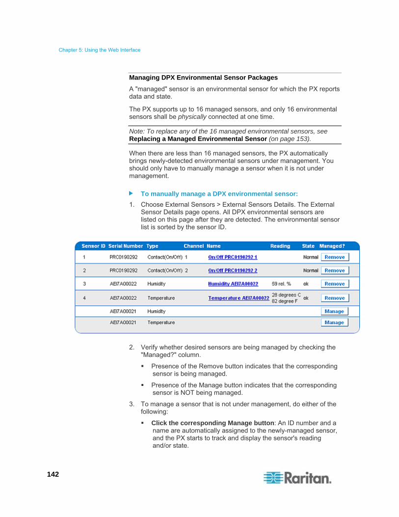
Chapter 5: Using the Web Interface
142
Managing DPX Environmental Sensor Packages
A "managed" sensor is an environmental sensor for which the PX reports data and state.
The PX supports up to 16 managed sensors, and only 16 environmental sensors shall be physically connected at one time.
Note: To replace any of the 16 managed environmental sensors, see Replacing a Managed Environmental Sensor (on page 153).
When there are less than 16 managed sensors, the PX automatically brings newly-detected environmental sensors under management. You should only have to manually manage a sensor when it is not under management.
To manually manage a DPX environmental sensor:
1. Choose External Sensors > External Sensors Details. The External Sensor Details page opens. All DPX environmental sensors are listed on this page after they are detected. The environmental sensor list is sorted by the sensor ID.
2. Verify whether desired sensors are being managed by checking the "Managed?" column.
Presence of the Remove button indicates that the corresponding sensor is being managed.
Presence of the Manage button indicates that the corresponding sensor is NOT being managed.
3. To manage a sensor that is not under management, do either of the following:
Click the corresponding Manage button: An ID number and a name are automatically assigned to the newly-managed sensor, and the PX starts to track and display the sensor's reading and/or state.

Chapter 5: Using the Web Interface
143
Manually assign an ID number to the sensor: A sensor becomes "managed" after manually assigning an ID number to it. The default name is automatically assigned. If another sensor already occupied the ID number at the time of assignment, that sensor becomes "unmanaged" after losing the ID number. For details, see Assigning or Changing the ID Number (on page 153).
4. It is recommended to reset the PX. See Recommendation for Environmental Sensor Operations (on page 154).
A sensor's default name comprises the sensor type and serial number, such as Humidity AEI7A00021. If the sensor is a contact closure sensor, a channel number is added to the end of the default name.
Note: When the total number of managed sensors reaches the maximum, you CANNOT manage additional sensors unless you remove or replace any managed ones. See Unmanaging Environmental Sensors (on page 152) for sensor removal and Assigning or Changing the ID Number (on page 153) for sensor replacement.
Configuring DPX Environmental Sensor Packages
You can assign new names to managed sensors for identifying them easily, and to provide them with location descriptions.
In addition, you can configure thresholds for numeric sensors so that the PX generates an alert or notification when environmental conditions detected by the sensors move outside of your ideal values.
Note: Only numeric sensors have threshold settings. Discrete (on/off) sensors, such as contact closure sensors, do not have thresholds.
To configure DPX environmental sensors:
1. Trigger the setup page for the desired DPX sensor by doing either of the following:
Choose External Sensors > External Sensors Setup. The External Sensor Setup page opens.
Select the desired sensor in the "Show setup of external sensor" field.
Choose External Sensors > External Sensors Details. The External Sensor Details page opens.
Click the desired sensor's name to open the sensor setup page.
2. If the selected sensor is a Raritan contact closure sensor, the On/Off Sensor Subtype field is displayed for you to select the detector/switch type:

Chapter 5: Using the Web Interface
144
Contact: The detector/switch detects the door lock or door open/closed status.
Smoke Detection: The detector/switch detects the appearance of smoke.
Water Detection: The detector/switch detects the appearance of water on the floor.
Vibration: The detector/switch detects the vibration in the floor.
3. Type a new name in the Sensor Name field.
A sensor's default name comprises the sensor type and serial number, such as Humidity AEI7A00021. If the sensor is a contact closure sensor, a channel number is added to the end of the default name.
4. Describe the sensor's location by assigning alphanumeric values to the X, Y and Z coordinates. See Describing the Sensor Location (on page 146). Optional.
5. Configure the thresholds for numeric sensors.

Chapter 5: Using the Web Interface
145
The "upper critical" and "lower critical" thresholds marked in red are points at which the PX considers the operating environment critical and outside the acceptable range.
Once critical, the sensor reading must drop below the "upper non-critical" threshold or raise above the "lower non-critical" threshold before the PX considers the reading to be acceptable again.
Note: Numeric sensors have a Thresholds panel but discrete (on/off) sensors do NOT.
6. Change the default hysteresis value as needed.
To disable the hysteresis, type 0 (zero).
To enable the hysteresis, type a non-zero value, which must meet the rules described in the table:
Threshold Criterion
Upper critical threshold Larger than or equal to the following formula:
upper non-critical threshold + hysteresis
Upper non-critical threshold Larger than or equal to the following formula:
lower non-critical threshold + (2 x hysteresis)
Lower non-critical threshold Larger than or equal to the following formula:
lower critical threshold + hysteresis
7. Click Apply.
8. If intended, select another managed sensor in the "Show setup of external sensor" field, and repeat the above steps to configure it.

Chapter 5: Using the Web Interface
146
Note: The number in parentheses following a sensor name is the ID number assigned to each sensor.
Note: The maximum ambient operating temperature (TMA) for the PX varies between 40 to 60 degrees Celsius, depending on the model and certification standard (CE or UL). If necessary, contact Raritan Technical Support for this information of your model.
Describing the Sensor Location
Chapter 5: Using the Web Interface
147
Optional: Use the X, Y and Z coordinates to describe each sensor's physical location. You can use these location values to track records of environmental conditions in fixed locations around your IT equipment. The X, Y and Z values act as additional attributes and are not tied to any specific measurement scheme. If you choose to, you can use non-measurement values. For example:
X = Brown Cabinet Row
Y = Third Rack
Z = Top of Cabinet
X, Y and Z coordinates may consist of:
X and Y: Any combination of alphanumeric characters. The value can be 0 to 24 characters long.
Z with the 'Rack Units ("U")' checkbox deselected: Any combination of alphanumeric characters, from 0 to 24 characters long.
Z with the 'Rack Units ("U")' checkbox selected: Any integer between 0 and 60.
A selected 'Rack Units ("U")' checkbox indicates that the height of the Z coordinate is measured in standard rack units. See Using Rack Units for the Z Coordinate Value (on page 147).
Note: To configure and retrieve these coordinate values over SNMP, see the PX MIB.
Using Rack Units for the Z Coordinate Value
You can use the number of rack units to describe the vertical location (Z coordinate) of an environmental sensor.
To use rack units for the Z coordinate value:
1. Choose Device Settings > PDU Setup. The PDU Setup page opens.
2. Select the 'Use Rack Units ("U") for Z coordinate' checkbox.
3. Click Apply.
Now you can use the number of rack units to describe the height of the sensor's location. See Managing DPX Environmental Sensor Packages (on page 142).

Chapter 5: Using the Web Interface
148
Viewing Sensor Readings and States
The Home page shows the following information for environmental sensors:
Number of managed sensors
Number of unmanaged sensors
A list of managed sensors with readings and/or states
Note that a temperature sensor displays its reading in both Celsius and Fahrenheit simultaneously.
"C" represents Celsius.
"F" represents Fahrenheit.
Some environmental sensors may show negative readings after being detected for the first time. Just wait for 1 to 3 seconds and they shall correctly show valid positive readings.
To view the readings and states from any other page, click Home in the navigation path at the top of the page.
Tip: Another page to view sensor readings and states is the External Sensors Details page. Choose External Sensors > External Sensors Details.

Chapter 5: Using the Web Interface
149
States of Managed Sensors
An environmental sensor shows the state after being managed.
Available sensor states vary depending on the sensor type -- numeric or discrete sensors. For example, a contact closure sensor is a discrete (on/off) sensor so it switches between three states only -- unavailable, alarm and normal.
Note: Numeric sensors show both numeric readings and sensor states to indicate environmental or internal conditions while discrete (on/off) sensors show sensor states only to indicate state changes.
Sensor states Applicable to
unavailable All sensors
Alarm Discrete sensors
Normal Discrete sensors
ok Numeric sensors
below lower critical Numeric sensors
below lower non-critical Numeric sensors
above upper non-critical Numeric sensors
above upper critical Numeric sensors
Note: The state change of a contact closure sensor occurs only if the sensor enters the new state for at least 1 consecutive sample.

Chapter 5: Using the Web Interface
150
"unavailable" State
The unavailable state means the connectivity or communications with the sensor is lost.
The PX pings all managed sensors at regular intervals in seconds. If it does not detect a particular sensor for three consecutive scans, the unavailable state is displayed for that sensor.
When the communication with a contact closure sensor's processor is lost, all detectors (that is, all switches) connected to the same sensor package show the "unavailable" state.
Note: When the sensor is deemed unavailable, the existing sensor configuration remains unchanged. For example, the ID number assigned to the sensor remains associated with it.
The PX continues to ping unavailable sensors, and moves out of the unavailable state after detecting the sensor on the first scan.
Connected sensors always show unavailable if they are NOT under management.
"Normal" State
This state indicates the sensor is in the normal state.
For a contact closure sensor, usually this state is the normal state you have set.
If the normal state is set to Normally Closed, the Normal state means the contact closure switch is closed.
If the normal state is set to Normally Open, the Normal state means the contact closure switch is open.
For Raritan's DPX floor water sensors, the normal state must be set to Normally Closed, which means no water is detected.
Note: See the Environmental Sensors Guide or Online Help for information on setting the normal state or dip switch. This guide is available on Raritan's Support page (http://www.raritan.com/support/).

Chapter 5: Using the Web Interface
151
"Alarm" State
This state means a discrete (on/off) sensor is in the abnormal state.
Usually for a contact closure sensor, the meaning of this state varies based on the sensor's normal state setting.
If the normal state is set to Normally Closed, the Alarm state means the contact closure switch is open.
If the normal state is set to Normally Open, the Alarm state means the contact closure switch is closed.
Tip: A contact closure sensor's LED is lit after entering the alarmed state. Determine which contact closure switch is "abnormal" according to the corresponding LED.
For a Raritan's DPX floor water sensor, the normal state must be set to Normally Closed, which means no water is detected. The alarmed state indicates that the presence of water is detected.
Note: See the Environmental Sensors Guide or Online Help for information on setting the normal state or dip switch. This guide is available on Raritan's Support page (http://www.raritan.com/support/).
"ok" State
Only a numeric sensor shows this state.
This state means the sensor reading is within the acceptable range as indicated below:
Lower Non-Critical threshold <= Reading < Upper Non-Critical threshold
Note: The symbol <= means smaller than (<) or equal to (=).
"below lower critical" State
This state means a numeric sensor's reading is below the lower critical threshold.
Reading < Lower Critical Threshold
"below lower non-critical" State
This state means the sensor reading is below the lower non-critical threshold.
Lower Critical Threshold <= Reading < Lower Non-Critical Threshold
Note: The symbol <= means smaller than (<) or equal to (=).

Chapter 5: Using the Web Interface
152
"above upper non-critical" State
This state means the sensor reading is above the upper non-critical threshold.
Upper Non-Critical Threshold <= Reading < Upper Critical Threshold
Note: The symbol <= means smaller than (<) or equal to (=).
"above upper critical" State
This state means the sensor reading is above the upper critical threshold.
Upper Critical Threshold <= Reading
Note: The symbol <= means smaller than (<) or equal to (=).
Unmanaging Environmental Sensors
When it is unnecessary to monitor a particular environmental factor, you can unmanage or release the corresponding environmental sensor so that the PX stops retrieving the sensor's reading and/or state.
Note: For the correct procedure of replacing a managed environmental sensor, see Replacing a Managed Environmental Sensor (on page 153).
To release a managed sensor:
1. Choose External Sensors > External Sensors Details. The External Sensor Details page opens.
2. Click Remove for the sensor that you want to release.
3. It is recommended to reset the PX. See Recommendation for Environmental Sensor Operations (on page 154).

Chapter 5: Using the Web Interface
153
After a sensor is removed from management, the ID number assigned to it is released and can be automatically assigned to any newly-detected sensor.
Replacing a Managed Environmental Sensor
There should be only a maximum of 16 environmental sensors managed and physically connected to the PX at one time. You must follow the procedure below to replace any managed DPX environmental sensor with a new one. Otherwise, you may end up with an unsupported configuration and the PX performance may be impacted.
To replace a managed environmental sensor:
1. Unmanage the environmental sensor(s) that you want to replace. See Unmanaging Environmental Sensors (on page 152).
2. Disconnect the unmanaged environmental sensor(s).
3. Connect the new environmental sensor(s) to the PX.
4. The PX will automatically manage the newly-connected environmental sensor(s) after detecting them.
5. It is recommended to reset the PX. See Recommendation for Environmental Sensor Operations (on page 154).
Assigning or Changing the ID Number
Instead of letting the PX assign an ID number to the sensor, you can manually assign any ID number to a detected or managed sensor no matter the desired number has been assigned to a sensor or not. With the feature, you can:
Have a unmanaged sensor managed
Change the ID number of a managed sensor
Replace a managed sensor with an identical type of sensor by assigning its ID number to another one
This feature is especially useful when there are 16 managed sensors because it removes a sensor from management while assigning its ID number to a unmanaged sensor at the same time.
Tip: You can also rearrange or change the ID numbers of all managed sensors at once via SNMP. See Changing ID Numbers of Environmental Sensors (on page 200).
To assign or change the ID number:
1. Choose External Sensors > External Sensors Details. The External Sensor Details page opens.
2. In the "Assign sensor" field, select a sensor.

Chapter 5: Using the Web Interface
154
In this field, each sensor is identified with a combination of the ID number (if available), serial number and sensor type, such as 1 AEI700021 Humidity. For a DPX contact closure sensor, a channel number is added to the end of the sensor type.
3. In the "to sensor ID" field, select an ID number you want.
4. Click Assign to assign the selected ID number to the selected sensor.
The selected sensor becomes managed if it was not previously.
If the selected ID number was previously associated with another sensor which remains connected to the PDU, that sensor becomes unmanaged after losing this ID number.
If the selected ID number was previously associated with a sensor which had been physically disconnected from the PDU, that sensor disappears from the web interface after losing this ID number.
The PX automatically re-sorts the environmental sensor list based on the latest sensor ID sequence.
5. It is recommended to reset the PX. See Recommendation for Environmental Sensor Operations (on page 154).
Recommendation for Environmental Sensor Operations
Any operation that changes the sensor ID of an environmental sensor will lead to changes in the environmental sensor tables in the web interface, SNMP, data log, CLP and IPMI.
If the user performs any PDU operations that involve any of the following sensor operations, it is recommended that the unit be reset. See Resetting the PX Device (on page 84).
Managing or unmanaging environmental sensors from the web interface
Physically adding, removing or replacing any environmental sensors
Reordering environmental sensors using SNMP
Re-assigning environmental sensor IDs from the web interface
Configuring and Using Alert Notifications
A benefit of the Raritan PDU's intelligence is its ability to notify you of and react to a change in conditions. This event notification is an "alert."

Chapter 5: Using the Web Interface
155
Components of an Alert
The alert is a condition statement: if "A" happens, then do "B". This condition statement describes what the PX does in certain situations and is composed of multiple parts:
Event: This is the "A" portion of an alert and describes the PX (or part of it) meeting a certain condition. For example, a specific outlet's voltage exceeds the upper non-critical threshold.
Policy: This is the "B" portion of an alert and describes the response to the event. For example, the PX notifies the system administrator of the event and records the event in the log.
Threshold or alarm: This is a condition met by the event. For example, a temperature critical threshold or a contact closure sensor alarm.
Destination: This is a target of the policy. For example, a system administrator's e-mail address.
Thresholds are user-configurable and are adjusted on the appropriate setup page:
Outlet-specific thresholds are assigned on the Outlet Setup page.
PDU-level thresholds are assigned on the PDU Setup page.
Environmental sensor thresholds are assigned on the External Sensors Setup page.
Destinations are configured as part of the Alert creation process. E-mail alert destinations require that the PX be set up for SMTP communication. See Configuring the SMTP Settings (on page 79).
How to Configure an Alert
The best way to create a new set of alerts, in sequence, is:
1. Create necessary destinations.
2. Create policies based on these destinations.
3. Create an alert that executes a policy.
By following this order, you have destinations to choose from when creating a policy, and policies to choose from when creating an alert. Otherwise, you will have to interrupt the alert creation process when you find the appropriate policy or destination is unavailable, and then create the alert again.
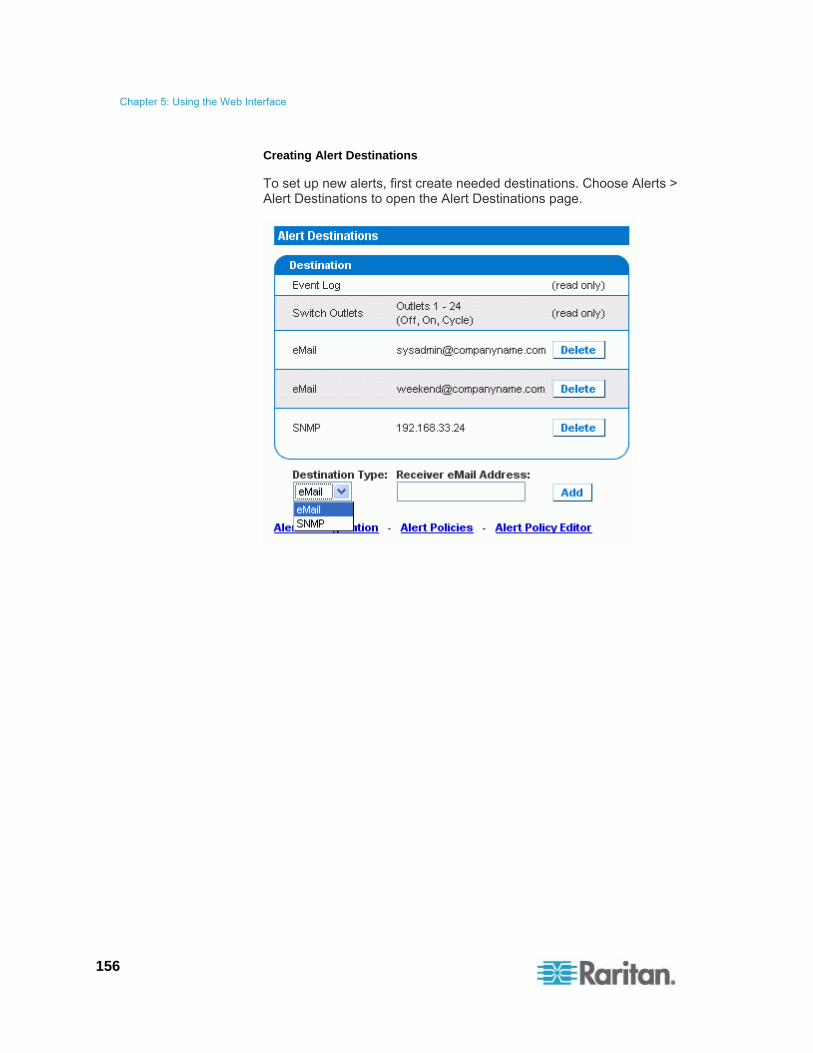
Chapter 5: Using the Web Interface
156
Creating Alert Destinations
To set up new alerts, first create needed destinations. Choose Alerts > Alert Destinations to open the Alert Destinations page.

Chapter 5: Using the Web Interface
157
The table on this page lists existing destinations configured on the PX. Two destinations, Event Log and Switch Outlets, are always available as part of system default destinations.
Event Log: Adding the event log destination to a policy causes the PX to record alert notifications in the system log. This destination cannot be deleted and additional ones of this type cannot be created.
Switch Outlets: Adding the Switch Outlets destination to a policy allows the PX to switch on/off or power cycle outlets in response to an event. This destination cannot be deleted and additional ones of this type cannot be created.
You can add and delete destinations. There are two user-configurable destination types:
eMail: Adding an e-mail destination to a policy causes the PX to send alert notifications to the specified e-mail address. Multiple e-mail destinations can be created.
SNMP: Adding an SNMP destination to a policy causes the ThresholdAlarm trap to be sent to the specified IP address. Multiple SNMP destinations can be created.
Tip: To generate all SNMP traps described in the MIB, choose Device Settings > Event Log to configure the SNMP feature instead. See Configuring SNMP Traps (on page 193) and Suggestion for SNMP Trap Configuration (on page 194).
To add an eMail destination:
1. Choose Alerts > Alert Destinations. The Alert Destinations page opens.
2. Select eMail in the Destination Type field.
3. Type the address of the recipient in the Receiver eMail Address field.
4. Click Add.
Note: If an address is configured for SMTP logging and all event-types are selected, that address will already receive notifications for an event that triggers an alert. However, you can use eMail destinations to send notifications to additional addresses. Furthermore, these notifications can be limited to the events that are relevant to those recipients.
To add an SNMP destination:
1. Choose Alerts > Alert Destinations. The Alert Destinations page appears.
2. Select SNMP in the Destination Type field.
3. Type the IP address of the SNMP manager in the Destination IP field. This must be a numeric IP address. DNS names are not allowed.

Chapter 5: Using the Web Interface
158
Tip: Although you can specify SNMP destinations in this field, it is highly recommended to specify the SNMP destination on the Event Log Settings page only. See Configuring SNMP Traps (on page 193) and Suggestion for SNMP Trap Configuration (on page 194).
4. Type the SNMP community string for this trap in the Community String field.
5. Click Add.
Note: SNMP alert traps are distinct from PX-specific traps. PX-specific traps are used for event logging if SNMP is configured on the Event Log Settings page. For SNMP alert destinations, the PX sends IPMI-PET (platform event traps) traps to the SNMP manager. The traps are generated in the alert configuration and sent out in IPMI-specific formats containing raw data. Details of these traps can be referenced at: http://www.intel.com/design/servers/ipmi/pdf/IPMIv2_0_rev1_0_E3_markup.pdf (http://www.intel.com/design/servers/ipmi/pdf/ipmiv2_0_rev1_0_e3_markup.pdf) (Chapter 17.16) and at: http://download.intel.com/design/servers/ipmi/PET100.pdf (http://download.intel.com/design/servers/ipmi/pet100.pdf).
Once added, your new destinations appear on the destinations table. To delete a destination, click Delete next to that destination.

Chapter 5: Using the Web Interface
159
Creating Alert Policies
Once your destinations are created, you can create policies to send notifications to these destinations. Choose Alerts > Alert Policy Editor to open the Alert Policy Editor page.
On the Alert Policy Editor page, you can modify an existing policy, or create a new policy. The table on this page lists all the configured alert destinations available.
To create an Alert Policy:
1. Choose Alerts > Alert Policy Editor.
2. Type a descriptive policy name in the New Policy Name field, or select an existing policy to modify in the Existing Policies field.
3. Select a destination in the Destinations table to add it to the policy. A single policy can notify multiple destinations. For example, you can record the alert in the event log AND e-mail a system administrator.

Chapter 5: Using the Web Interface
160
Event Log: The PX will record alert notifications in the system log.
Addresses listed under eMail: The PX will send alert notifications to the specified e-mail address.
Addresses listed under SNMP: An SNMP trap will be sent to the specified IP address.
Current Outlet: The PX will set the power state of the outlet that generated the alert - turn the outlet OFF or ON, or to cycle the power to the outlet.
Note: Current Outlet applies only when the event is an outlet event. It has no effect for other types of events. See Creating Alerts (on page 161).
Outlets listed under Switch Outlet: The PX will set the power state of the selected outlets - turn the outlets OFF or ON, or to cycle power to the outlets.
4. Click Create to create the new policy, or click Modify if modifying an existing one.
Note: For PX models without outlet switching, the Current Outlet and Switch Outlet destinations have no effect.
These policies are now available as a response when creating an Alert. When the alert is triggered, outlets are switched and alert notifications are sent to the event log, e-mail accounts, and SNMP managers as dictated by the selected policy.
When Event Log is set as a destination, alert events are sent to all logging services enabled on the Event Logs page. This can result in duplicate messages if the email and SNMP destinations for this Policy are the same as those used for event logging. In this case, select different SNMP and email destinations to avoid duplicate notices.

Chapter 5: Using the Web Interface
161
Creating Alerts
The Alert Configuration page is where you specify how the PX responds to certain events. First describe an event that triggers an alert and then select the policy the PX should take in response.
Warning: It is strongly suggested to avoid creating too many alerts. When there are over 100 or even 200 alerts created, the PX performance slows down dramatically.
To Create an Alert:
1. Choose Alerts > Alert Configuration. The Alert Configuration page opens.
2. Under the Event drop-down list, select the segment this event affects.
Unit: refers to the PX device. Temperature refers to the internal temperature as measured on the PCB board.
Line: refers to a current carrying line. Three-phase PDUs have three current lines, and single-phase PDUs only have one.
Outlet: refers to a specific, single outlet on the PX device.
Circuit Breaker: refers to an internal circuit breaker that governs current to a group of outlets.
Environmental Temperature: refers to the temperature as measured by a specific external temperature probe. The PX must have environmental temperature probes configured and connected to the PDU for this alert event to trigger.
Environmental Humidity: refers to the humidity as measured by a specific external humidity probe. The PX must have environmental humidity probes configured and connected to the PDU for this alert event to trigger.

Chapter 5: Using the Web Interface
162
Environmental Air Pressure: refers to the air pressure as measured by a specific Raritan air pressure probe. The PX must have air pressure probes configured and connected to the PDU for this alert event to trigger.
Environmental Air Flow: refers to the air flow as measured by a specific Raritan air flow probe. The PX must have air flow probes configured and connected to the PDU for this alert event to trigger.
Environmental On/Off: refers to the contact closure status as detected by a specific external contact closure probe. The PX must have contact closure probes configured and connected to the PDU for this alert event to trigger.
See DPX Environmental Sensor Packages (on page 140) for information on configuring DPX environmental sensors.
3. If you selected a Line, Outlet, or Circuit Breaker segment, or any environmental sensor type, such as Environmental Temperature and Environmental Humidity, indicate the specific line, outlet, circuit breaker or environmental sensor using the new drop-down list that appears.
4. Select an alert event that occurs to the specified segment. The list of events depends on the selected segment.
5. Pick an event direction. This describes how a numeric sensor's threshold must be exceeded or how a discrete sensor changes its state to trigger the alert.
Assert & Deassert: The alert is triggered when the numeric sensor's measured value moves past a threshold in either direction or when the discrete sensor's state change occurs.
Assert: This alert is triggered only when the numeric sensor's measured value moves past the threshold (above an upper threshold or below a lower threshold), or when the discrete sensor changes its state from Normal to Alarm. This means the status of the described event transits from FALSE to TRUE.
Deassert: This alert is triggered only when the numeric sensor's measured value returns towards "normal" from beyond the threshold (below an upper threshold or above a lower threshold), or when the discrete sensor changes its state from Alarm to Normal. This means the status of the described event transits from TRUE to FALSE.
For example, if you select "Environmental Temperature above upper critical threshold" and set the event direction to Assert & Deassert, the selected policy executes when the temperature of the cabinet exceeds the critical threshold. When the environment cools and the temperature drops below the critical threshold, the policy executes again.

Chapter 5: Using the Web Interface
163
6. Select a policy to execute from the Policy drop-down list. This list includes all of the alert policies created on the Alert Policy Editor page.
Note: Any policy that includes an operation on the "current outlet" must be associated only with outlet based events and never with non-outlet based events such as temperature or unit level events. Failure to follow this rule can result in unpredictable results including turning on or off a random outlet when events occur. See Creating Alert Policies (on page 159). For the outlet current threshold events, avoid choosing an alert policy that cycles the power to "Current Outlet" because the "cycle current outlet" destination may generate the infinite output cycle loop.
7. Click Add.
Added alerts are now tracked by the PX. When an alert's event conditions are met, the associated policy executes.
Note: It is possible for an alert to set the same outlet state twice. For example, a temperature threshold Alert is created with the Event Direction set to Assert & Deassert. This alert calls a policy that turns the outlet OFF. In such a scenario, the alert triggers the outlet OFF policy once when the temperature rises above the threshold, and once more when the temperature drops below the threshold. Any event logs recording the outlet state note that the power to this outlet was turned OFF twice in a row.
Important: All pre-existing "environmental sensor" alerts will be deleted after the copy operation is completed. See Copying a PX Configuration (on page 92).
Sample Alerts
Sample Outlet-Level Alert
In this example, we want the PX to notify us when the current draw on Outlet 6 approaches the critical limit. To do that we would set up an alert like this:
Event: Outlet; Outlet 6 (6); current above upper critical threshold
Event Direction: Assert & Deassert
Policy: Log + Notify
Event:
a. Select "Outlet" to indicate we are measuring at the outlet level.
b. Specify "Outlet 6 (6)" because that is the outlet in question.

Chapter 5: Using the Web Interface
164
c. Select "current above upper non-critical threshold" because we want to know when the PDU crosses into the warning range BEFORE the current draw is at critical levels.
Event Direction:
Set to "Assert & Deassert" because we want to know when the current on the outlet is higher than normal AND we want to know when it has returned to normal.
Policy:
Select the example policy "Log + Notify."
Our example policy has Event Log, the IP address of an SNMP manager, and the email address of the facilities manager checked. With these settings, the PX records the alert in its internal Event Log, send a trap to an SNMP manager, and email the facilities manager each time the current rises above and falls below the non-critical threshold.
Sample Unit-Level Alert
In this example, we want the PX to shut down most of its outlets if the PX becomes too hot. However, since mission-critical servers are plugged into Outlets 1 and 2, we want to leave them running. Our alert would look something like this:
Event: Unit; temperature above upper non-critical threshold
Event Direction: Assert
Policy: Non-Essential OFF
Event:
a. Specify "Unit" since the whole PX is our concern.
b. Set the upper non-critical temperature as our "warning" mark because we want the temperature crossing that threshold to trigger the alert.
Event Direction:
Set to "Assert" only, since we only want to take action when the temperature is past the upper non-critical threshold.
Policy:
Select the example policy "Non-Essential OFF."
This example policy has the Switch Outlet destination selected and Outlet 1 and Outlet 2 set to ON. The remaining outlets are set to OFF to reduce the power draw through the PX and the amount of heat expelled into the rack.
Chapter 5: Using the Web Interface
165
Sample Environmental Alert 1
In this example, our PX is equipped with environmental temperature sensors and we want to create an alert to address abnormally high ambient temperatures. For instance, if the ventilation system in the server room were to stop working. We would place our environmental temperature sensors outside of the rack to measure the room temperature. Then we would configure an alert to look something like this:
Event: Environmental Temperature; temperature above upper critical threshold
Event Direction: Assert
Policy: Outlets OFF + Facilities
Event:
a. Configure the PX to monitor the "Environmental Temperature" sensors.
b. Configure it to trigger an alert when it measures a "temperature above upper critical threshold."
Event Direction:
Set to "Assert" only, since we only want to take actions when the temperature is above the upper critical threshold.
Policy:
Select the example policy "Outlets OFF + Facilities."
This example policy would have the following destinations checked:
Switch Outlets, with all outlets set to OFF
E-mail for the system administrator and e-mail for the facilities manager
This way, all equipment powered through the PX device would power OFF to avoid damage and prevent from adding more heat to the room. The system admin and the facilities manager would both receive a notification stating that the room temperature was too high.

Chapter 5: Using the Web Interface
166
Sample Environmental Alert 2
We can configure a complimentary alert that looks something like this:
Event: Environmental Temperature; temperature above upper non-critical threshold
Event Direction: Deassert
Policy: Outlets ON + Facilities
This powers on all outlets again when the temperature is normal.
Event:
a. Use the "Environmental Temperature" sensors to monitor the ambient temperature of the room.
b. Select "temperature above upper non-critical threshold" so that the PX checks whether the temperature is above or below the upper non-critical threshold, which is generally set as a boundary between normal and warning states.
Event Direction:
Set to "Deassert" only, since we only want to power ON the outlets again when the ambient temperature stops being above the non-critical threshold. This would indicate that the temperature has dropped below the warning level and is now normal again.
Policy:
Select the example policy "Outlets ON + Facilities."
This example policy would have the following destinations checked:
Switch Outlets with all outlets set to ON
E-mail for the system administrator and e-mail for the facilities manager
This way, when the temperature returns to normal (for example, if the ventilation system works properly again), the PX powers on all of its outlets. Additionally, the system administrator and the facilities manager receive e-mail notification stating that the room temperature dropped below the warning level.
A Note about Untriggered Alerts
In some cases, a measurement exceeds a threshold causing the PX to generate an alert. The measurement then returns to a value within the threshold, but the PX does not generate an alert message for the Deassertion event. Such scenarios can occur due to the hysteresis tracking the PX uses.

Chapter 5: Using the Web Interface
167
What is Threshold Hysteresis?
The hysteresis setting determines when a threshold condition is reset. This diagram illustrates how hysteresis values relate to thresholds:
Upper Critical Threshold
Hysteresis Upper Critical Reset
Upper Non-Critical Threshold
Hysteresis Upper Non-Critical Reset
Lower Non-Critical Reset
Hysteresis Lower Non-Critical Threshold
Lower Critical Reset
Hysteresis Lower Critical Threshold
The hysteresis values define a reset threshold. For upper thresholds, the measurement must fall past this reset threshold before a deassertion event is generated. For lower thresholds, the measurement must rise above this reset threshold before a deassertion event is generated.
See Default Hysteresis Values for Thresholds (on page 283) for default hysteresis values of each measurement type.
How to Disable the Hysteresis
By default, the PX assigns a hysteresis value for each setting in the Thresholds panels on the Outlet Setup and PDU Setup pages. You can disable the hysteresis for any setting.
To disable a specific hysteresis:
1. Open the desired page:
To open the Outlet Setup page, choose Details > Outlet Setup.
To open the PDU Setup page, choose Device Settings > PDU Setup.

Chapter 5: Using the Web Interface
168
2. Type 0 (zero) for the hysteresis setting you want to disable in the Thresholds panel.
Tip: To re-enable the hysteresis use, type a non-zero value to replace the zero value.
Example: When Hysteresis is Useful
This example demonstrates when a deassertion hysteresis is useful.
The current critical threshold for Outlet 1 is set to 10 amps (A). The current draw rises to 11A, triggering a Current Critical alert. The current then continues to fluctuate between 9.8A and 11A.
With the hysteresis set to 0.9A, the PX continues to indicate that the current in Outlet 1 is above critical. With the hysteresis disabled (that is, set to zero), the PX would de-assert the condition each time the current dropped to 9.9A, and re-assert the condition each time the current reached 10A or higher. With the fluctuating current, this could result in a number of repeating SNMP traps, and/or an e-mail account full of repeating SMTP alert notifications.
Example: When to Disable Hysteresis
This is an example of when you want to disable the use of hysteresis for outlets.
The upper non-critical threshold for current in Outlet 2 is set to 8A. In normal usage, Outlet 2 draws 7.6A of current. A spike in demand causes the current to reach 9A, triggering an alert. The current then settles to the normal draw of 7.6A.
With the hysteresis disabled (that is, set to zero), the PX de-asserts the condition once the current drops to 7.9A. If the hysteresis remained enabled and the current never dropped to 7.0A, the outlet would still be considered above non-critical. The condition would not de-assert, even if the current draw returned to normal.
Setting Up Event Logging
By default, the PX captures certain system events and saves them in a local (internal) event log. You can expand the scope of the logging to also capture events in the NFS, SMTP, and SNMP logs.
Note: When configuring the PX to use more than one logging method, configure each method individually and apply the changes before configuring the next.

Chapter 5: Using the Web Interface
169
Configuring the Local Event Log
Follow this procedure to determine whether the local logging function is enabled and which types of events are logged in the local log.
To configure the local event log:
1. Choose Device Settings > Event Log. The Event Log Settings page opens. The Local Logging panel appears first. This panel controls the local event log.
2. The local event log is enabled by default. To turn it off, deselect the Local Logging Enabled checkbox.
3. By default, 20 log entries appear on each page of the local event log when it is displayed. To change this, type a different number in the Entries Shown Per Page field.
4. To clear all events from the local event log:
a. Click Clear.
b. Two buttons appear - Really Clear and Cancel.
c. Click Really Clear to complete the clear operation or Cancel to terminate it.

Chapter 5: Using the Web Interface
170
5. By default, when the local event log is enabled, seven event types appear in the Event Log Assignments panel to the right. All are enabled by default. To disable any event types, deselect the corresponding checkboxes.
Note: See Event Types (on page 283) for detailed information on event types.
6. Click Apply.
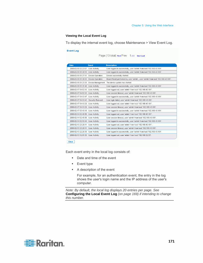
Chapter 5: Using the Web Interface
171
Viewing the Local Event Log
To display the internal event log, choose Maintenance > View Event Log.
Each event entry in the local log consists of:
Date and time of the event
Event type
A description of the event
For example, for an authentication event, the entry in the log shows the user's login name and the IP address of the user's computer.
Note: By default, the local log displays 20 entries per page. See Configuring the Local Event Log (on page 169) if intending to change this number.

Chapter 5: Using the Web Interface
172
Configuring the NFS Logging
This procedure describes how to enable the Network File System (NFS) logging function and determine which types of events are recorded in the NFS log file.
To configure the NFS logging:
1. Choose Device Settings > Event Log. The Event Log Settings page opens. The NFS Logging panel controls NFS logging.
2. Select the NFS Logging Enabled checkbox.
3. Type the IP address of the NFS server in the NFS Server field.
4. Type the name of the shared NFS directory in the NFS Share field.
5. Type the name of the NFS log file in the NFS Log File field. Default is evtlog.
6. By default, when NFS logging is enabled, eight event types appear in the Event Log Assignments panel to the right. All are disabled by default. To enable any event types, select the corresponding checkboxes.
7. Click Apply.

Chapter 5: Using the Web Interface
173
8. Reset the PX by choosing Maintenance > Unit Reset. This step is REQUIRED for the NFS logging settings to take effect.
Configuring the SMTP Logging
You can enable the Simple Mail Transfer Protocol (SMTP) logging function and determine which types of events are recorded in the SMTP log file.
To configure the SMTP logging:
1. Ensure the SMTP server settings have been configured properly. See Configuring the SMTP Settings (on page 79).
2. Choose Device Settings > Event Log. The Event Log Settings page opens. The SMTP Logging panel controls SMTP logging.
3. Select the SMTP Logging Enabled checkbox.
4. Type the receiver's email address in the Receiver Email Address field.
5. By default, when SMTP logging is enabled, seven event types appear in the Event Log Assignments panel to the right. All are disabled by default. To enable any event types, select the corresponding checkboxes.
6. Click Apply.
Important: You must configure the SMTP settings first, for SMTP logging

Chapter 5: Using the Web Interface
174
to work. See Configuring the SMTP Settings (on page 79).
Configuring the SNMP Logging
Event logging can be performed by sending SNMP traps to a maximum of 3 third-party SNMP destinations. See Configuring SNMP Traps (on page 193) for enabling SNMP Event Logging.
Configuring the Syslog Forwarding
To make the PX automatically forward events to a specific destination, enable the syslog forwarding function and determine which types of events should be logged in the syslog record.
Note: After enabling Syslog Forwarding, a "--MARK--" message may appear in the Syslog record every 20 minutes. This is a keep-alive method used by the PX.
To configure the Syslog Forwarding:
1. Choose Device Settings > Event Log. The Event Log Settings page opens. The Syslog Forwarding panel controls forwarding of system logs.
2. Select the Enable Syslog Forwarding checkbox.
3. In the IP Address field, type the IP address to which syslog is forwarded.
4. By default, when Syslog Forwarding is enabled, seven event types appear in the Event Log Assignments panel to the right. All are disabled by default. To enable any event types, select the corresponding checkboxes.

Chapter 5: Using the Web Interface
175
5. Click Apply.
Note: If you want to disable Syslog forwarding, deselect all checked event types under the Syslog column and click Apply. Then deselect Enable Syslog Forwarding. If event types are still selected in the Syslog column when you disable Syslog forwarding, you may be unable to deselect those event types from the internal event log list.
Outlet Grouping
Using the Outlet Grouping feature, you can combine outlets from separate PX PDUs into a single logical group, allowing control from a single PX. Outlets that are grouped together power on and power off together in unison, making outlet grouping ideal for servers with power supplies plugged into multiple PX devices.
Users, or the group they belong to, must have the Outlet Group Configuration permission under User/Group System Permissions in order to manage or access an Outlet Group. Only locally authenticated users may perform actions on outlet groups.
Outlet Grouping supports adding outlets from up to four other PX devices. All PDUs must be accessible over IP and must be running firmware version 1.1 or higher.
Note: Outlet Grouping may not work properly if you disable IPMI over LAN. See Disabling IPMI over LAN (on page 182).

Chapter 5: Using the Web Interface
176
Identifying Other PX Devices
To add outlets from other PX devices, you must first identify which PX devices are sharing their outlets.
To identify other PX devices:
1. Choose Outlet Groups > Outlet Group Devices. The Outlet Group Devices page opens.
2. Type a name to identify the PX you want to add in the Name field.
3. Type the IP Address of the PX you want to add in the IP Address field.
4. Type the admin username and password in the Username and Password fields. Do NOT leave these fields blank as they can authenticate on the PX device being added.
5. Click Add/Modify. The new PX is now available for outlet grouping.
To modify the name or the Username and Password used to access a participating PX device, retype the information for the same PX and click Add/Modify again.
Note: You can re-add the PX PDU you are accessing if you deleted it from the list, or modify its details by using the IP address 127.0.0.1.

Chapter 5: Using the Web Interface
177
Grouping Outlets Together
Once the participating PX devices have been added to the list of outlet group devices, their individual outlets can be grouped together. Outlets that are grouped together power on and power off in unison, using a control panel from the PX where the outlet group was created.
To group outlets together:
1. Choose Outlet Groups > Outlet Group Editor. The Outlet Group Editor page opens.
2. Type a name for the outlet group in the Name field. It is a good idea to give the outlet group a recognizable name that helps identify the device(s) connected to it.
Note: You cannot modify the name of an outlet group after the group is created.
3. Type a comment for the outlet group in the Comment field. This can be used to further identify device(s) powered by the group.
4. Under the Capabilities field, select the checkboxes of the power control abilities you want available for this outlet.

Chapter 5: Using the Web Interface
178
5. A list of available PX devices and their outlets appears under Collection of Real Outlets. Select the checkbox representing the desired outlet to make it part of the outlet group. All outlets that are selected are grouped together when you click Create.
Note: You should not add one outlet to more than one outlet group.
6. Click Create. The outlet group is created and added to the Outlet Groups list.
Grouped outlets are designed to be controlled together. Avoid doing anything to affect these outlets individually, such as turning one of the outlets ON or OFF, or unplugging one of the participating PX devices. Once grouped, power control to those outlets should be managed from the Outlet Groups Details page.
Viewing and Controlling Outlet Groups
Any outlet groups created from this PX appear on the Outlet Groups Details page. On this page, you can power ON, OFF or CYCLE the outlet group (if the capability is available).
To control the power to an outlet group:
1. Choose Outlet Groups > Outlet Group Details. The Outlet Groups list appears.
Note: Only outlet groups created through this specific PX appear in this Outlet Groups list. Outlet groups created through another PX do not display here, even if they contain outlets from this PDU.
2. To turn an outlet group on, off, or cycle the power to it, click On, Off, or Cycle in the row of the outlet group.
3. Click OK when prompted to confirm the operation.
Chapter 5: Using the Web Interface
179
4. The page refreshes once to indicate that the desired command was performed, and again a few seconds later to update the status of the outlet group.
Note: The page must finish loading or refreshing before selecting an action. If you select an action before the page has finished updating the status of all outlet groups, the command is ignored.
If you want to view or edit the composition of an outlet group, click on the name of the outlet group to open the Outlet Group Editor page for that group.
Editing or Deleting Outlet Groups
1. Choose Outlet Groups > Outlet Group Editor. The Outlet Group Editor page opens.
2. Select the desired outlet group in the Outlet Groups field.
3. The details for the outlet group appear. Change the comment, capabilities, or the included outlets if you are modifying the group.
4. Click Modify to save any changes made, or Delete to remove that outlet group.
Note: You cannot modify the name of an outlet group after the group is created.
Deleting Outlet Group Devices
To delete a PX from outlet grouping when it is no longer available or in use:
1. Choose Outlet Groups > Outlet Group Devices. The Outlet Group Devices page opens, showing a list of PX PDUs for outlet grouping.
2. Click Delete for the PX you want to remove.
Note: If you delete a PX that still has outlets in a group, it also removes associated outlets from that group, but the group still exists. Remove the group itself using the Outlet Group Editor. You should not delete the host device (that is, the PX you are now accessing) from the Outlet Group Devices list. If you do, you can add it back to the list using the IP address 127.0.0.1.

Chapter 5: Using the Web Interface
180
Setting the FIPS Mode
The PX supports the Security Requirements for Cryptographic Modules of the Federal Information Processing Standards (FIPS), which is defined in the FIPS PUB 140-2 (http://www.nist.gov/cmvp/), Annex A: Approved Security Functions. These standards are used to protect the Federal government's sensitive information with the cryptographic-based security systems in the U.S. and Canada.
FIPS Limitations
In the FIPS mode, only the FIPS approved security algorithms are supported, resulting in the necessity to disable or stop supporting some algorithms implemented with the PX.
Restrictions in the FIPS mode:
HTTP access is NOT supported, and HTTPS access is forced automatically.
Telnet access is NOT supported, but SSH access remains supported.
The following SSH algorithms are supported:
Ciphers:
AES128-CBC
3DES-CBC
AES256-CBC
Hash:
HMAC-SHA1-96
HMAC-SHA1
LDAP authentication is NOT supported. Only LDAPS (SSL enabled) authentication is supported.
You must use FIPS required ciphers for SSL.
Radius authentication is NOT supported.
The SNMP v1/v2c protocol is NOT supported, but the SNMP v3 protocol is still supported.
If the SNMP v3 protocol is enabled, the PX automatically forces the SNMP v3 encryption, which cannot be reset. After enabling this protocol, you must:
Enable the authentication and privacy to set the security level to authPriv.
Select SHA as the authentication algorithm.

Chapter 5: Using the Web Interface
181
Select AES as the privacy algorithm.
Note: MD5 and DES are NOT FIPS approved algorithms.
Only IPMI v2.0 is supported. The following algorithms are supported:
Authentication algorithms:
RAKP-HMAC-SHA1
RAKP-HMAC-SHA256
Integrity algorithms:
HMAC-SHA1-96
HMAC-SHA256-128
Encryption algorithms:
AES-CBC-128
ipmitool:
You must use the lanplus interface. See IPMI in the FIPS Mode (on page 281).
The parameter used with the -C option for ciphersuite must be 3.
FIPS Impact on Integration
The PX can be integrated with other Raritan or non-Raritan products. See Integration (on page 246).
CC-SG integration is affected by the limitations caused by the FIPS mode. You must upgrade your CC-SG to version 5.3 or later in order to manage or control the PX running in the FIPS mode.
Power IQ must use SNMP v3 to manage or control the PX running in the FIPS mode.
Configuring the FIPS Mode
Only the admin user can enable or disable the FIPS mode of the PX using any interfaces. The PX always sends SNMP v1/v2c traps whenever the FIPS mode is enabled or disabled.
To activate the FIPS mode:
1. Choose Device Settings > FIPS Setting.
2. Click Enable FIPS.
3. An alert message appears, listing the limitations that will be applied to the FIPS mode.
4. Click Really Enable FIPS to confirm this operation.
5. The PX will reset. Wait until the reset is complete.
Chapter 5: Using the Web Interface
182
After enabling the FIPS mode, the message "FIPS mode is set" is displayed in blue in the status panel. See Status Panel (on page 61).
To deactivate the FIPS mode:
1. Choose Device Settings > FIPS Setting.
2. Click Disable FIPS.
3. An alert message appears, stating that weak ciphers are permitted after deactivating the FIPS mode.
4. Click Really Disable FIPS to confirm this operation.
5. The PX will reset. Wait until the reset is complete.
After disabling the FIPS mode, the message "FIPS mode is not set" is displayed in the status panel. See Status Panel (on page 61).
Disabling IPMI over LAN
The PX enables the support for IPMI over LAN by default.
Enabling IPMI over LAN exposes the PX to certain security risks that are intrinsic to the IPMI protocol. To avoid these IPMI security risks, you can disable IPMI over LAN. Note that the outlet grouping function may not work properly if you disable IPMI over LAN because the PX in an outlet group communicates using IPMI over LAN. See Outlet Grouping (on page 175).
Tip: The alternative to protect the PX from the security risks when IPMI over LAN is enabled is to set up other types of security algorithms, such as the firewall.
Only the users who belong to the Admin user group can enable or disable IPMI over LAN.
To disable IPMI over LAN:
1. Choose Device Settings > IPMI Over LAN.
2. Click Disable IPMI Over LAN.
3. An alert message appears, indicating that the outlet group functionality may be comprised after disabling IPMI over LAN, and the PX will reset.
4. Click Really Disable IPMI Over LAN to confirm this operation.
5. The PX will reset. Wait until the reset is complete.

Chapter 5: Using the Web Interface
183
After disabling IPMI over LAN, the message "IPMI over LAN disabled" is displayed in the status panel. See Status Panel (on page 61).
To enable IPMI over LAN:
1. Choose Device Settings > IPMI Over LAN.
2. Click Enable IPMI Over LAN.
3. An alert message appears, indicating that the PX will reset.
4. Click Really Enable IPMI Over LAN to confirm this operation.
5. The PX will reset. Wait until the reset is complete.
After enabling IPMI over LAN, the message "IPMI over LAN enabled" is displayed in blue in the status panel. See Status Panel (on page 61).
Diagnostics
The PX provides the following tools in the web interface for diagnosing potential networking issues.
Network Interface
Network Statistics
Ping Host
Trace Route to Host
Device Diagnostics
Network Interface Page
The PX provides information about the status of your network interface.
To view information about your network interface:
Choose Diagnostics > Network Interface. The Network Interface page opens.
The following information is displayed:
The Ethernet interface state
The LAN port that is currently active
To refresh this information:
Click Refresh.

Chapter 5: Using the Web Interface
184
Network Statistics Page
The PX provides statistics about your network interface.
To view statistics about your network interface:
1. Choose Diagnostics > Network Statistics. The Network Statistics page opens.
2. Click Refresh. The relevant information is displayed in the Result field.

Chapter 5: Using the Web Interface
185
Ping Host Page
Ping is a network tool used to test whether a particular host or IP address is reachable across an IP network. You can use it to determine if a target server or another PX is accessible.
To ping the host:
1. Choose Diagnostics > Ping Host. The Ping Host page appears.
2. Type either the hostname or IP address into the IP Address/Host Name field.
Note: The host name cannot exceed 232 characters in length.
3. Click Ping. The ping results are displayed in the Result field.
Trace Route to Host Page
Trace route is a network tool used to determine the route taken to the provided hostname or IP address.
To trace the route to the host:
1. Choose Diagnostics > Trace Route to Host. The "Trace Route to Host" page opens.
2. Type either the IP address or host name into the IP Address/Host Name field.
Note: The host name cannot exceed 232 characters in length.
3. Choose the maximum hops from the drop-down list (5 to 50 in increments of 5).

Chapter 5: Using the Web Interface
186
4. Click Trace Route. The trace route command is executed for the given hostname or IP address and the maximum hops. The output of trace route is displayed in the Result field.
Saving a Device Diagnostics File
When instructed by Raritan Technical Support, download the diagnostics file from the PX device and send it to Raritan Technical Support for troubleshooting.
To download a device diagnostics file:
1. Choose Diagnostics > Device Diagnostics. The Device Diagnostics page opens.
2. Click Save To File. A File Download message appears.
3. Click Save to save the file onto your computer.

Chapter 5: Using the Web Interface
187
Using Online Help
The PX Online Help (User Guide) is accessible over the Internet.
To use online help, Active Content must be enabled in your browser. If you are using Internet Explorer 7, you must enable Scriplets. Consult your browser help for information on enabling these features.
To use the PX online help:
1. Click the "Help - User Guide" link in the Status Panel. The online help opens in the default web browser.
2. To view the content of any topic, click the topic in the left pane.
3. To select a different topic, do any of the following:
To view the next topic, click in the toolbar.
To view the previous topic, click .
To view the first topic, click .
4. To expand or collapse a topic that contains sub-topics, do the following:
To expand any topic, click the white arrow , or double-click that topic.
To collapse any expanded topic, click the black, gradient arrow , or double-click the expanded topic.
5. To search for specific information, type the key word(s) or string(s) in the Search text box, and press Enter or click (Search) to start the search.
If necessary, select the "Match partial words" checkbox to include information matching part of the words entered in the Search text box.
The search results are displayed in the left pane.
6. To have the left pane show the list of topics, click the Contents tab at the bottom.
7. To have the left pane show the Index page, click the Index tab.
8. To email the URL link to the currently selected topic to any person, click in the toolbar.
9. To email your comments or suggestions regarding the online help to
Raritan, click .
10. To print the currently selected topic, click .

188
This SNMP section helps you set up the PX for use with an SNMP manager. The PX can be configured to send traps to an SNMP manager, as well as receive GET and SET commands in order to retrieve status and configure some basic settings.
In This Chapter
Enabling SNMP .....................................................................................189 Configuring SNMP Traps.......................................................................193 SNMP Gets and Sets ............................................................................196
Chapter 6 Using SNMP

Chapter 6: Using SNMP
189
Enabling SNMP
By default, SNMP v1/v2c is enabled on the PX so it can communicate with an SNMP manager. If you have disabled the SNMP, it must be enabled for communication with an SNMP manager.
Note that read-only access is enabled and the community string is raritan_public.
To enable SNMP:
1. Choose Device Settings > SNMP Settings. The SNMP Settings page opens.
2. Select the Enable SNMP Agent checkbox to enable communication with remote SNMP managers.
3. Select the Enable SNMP v1 / v2c Protocol checkbox to enable communication using SNMP v1 or v2c protocol.
Type the SNMP read-only community string in the Read Community field and the read/write community string in the Write Community field. Default community strings are "raritan_public" and "raritan_private" respectively.

Chapter 6: Using SNMP
190
Note: In the FIPS mode, SNMP v1 / v2c protocol is NOT supported so its settings become unavailable. See FIPS Limitations (on page 180).
4. Select the Enable SNMP v3 Protocol checkbox to enable communication using SNMP v3 protocol.
Additionally, select the Force Encryption checkbox to force using encrypted SNMP communication.
Note 1: In the FIPS mode, the Force Encryption checkbox is automatically selected when enabling the SNMP v3 protocol.
Note 2: To perform SNMP v3 operations successfully, make sure the name of your user group does NOT contain spaces.
5. Type the SNMP MIBII sysLocation value in the System Location field.
6. Type the SNMP MIBII sysContact value in the System Contact field.
7. Click on the "here" link at the bottom to download an SNMP MIB for your PX to use with your SNMP manager.
8. Click Apply.
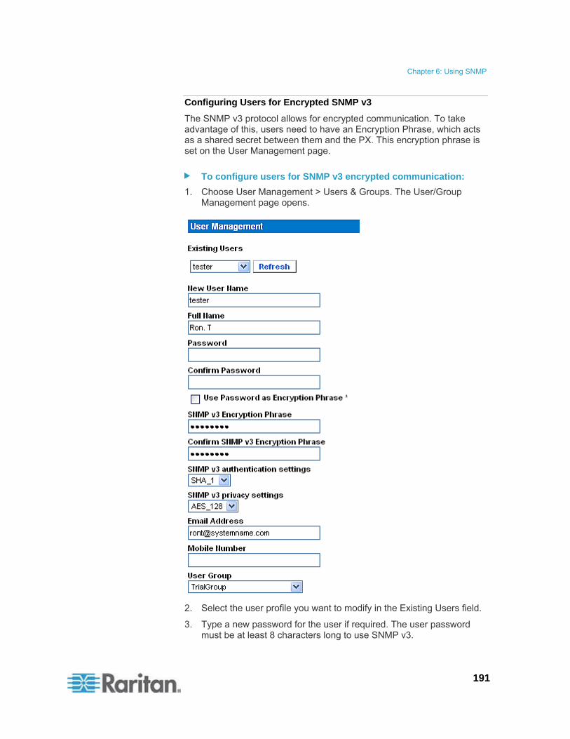
Chapter 6: Using SNMP
191
Configuring Users for Encrypted SNMP v3
The SNMP v3 protocol allows for encrypted communication. To take advantage of this, users need to have an Encryption Phrase, which acts as a shared secret between them and the PX. This encryption phrase is set on the User Management page.
To configure users for SNMP v3 encrypted communication:
1. Choose User Management > Users & Groups. The User/Group Management page opens.
2. Select the user profile you want to modify in the Existing Users field.
3. Type a new password for the user if required. The user password must be at least 8 characters long to use SNMP v3.

Chapter 6: Using SNMP
192
4. There are two ways to determine the SNMP v3 encryption phrase.
To use the user password as the Encryption Phrase, select the "Use Password as Encryption Phrase" checkbox.
To specify a different encryption phrase, deselect this checkbox. Type a new phrase in the SNMP v3 Encryption Phrase field, and once again in the Confirm SNMP v3 Encryption Phrase field. The SNMP v3 Encryption phrase must be at least 8 characters long.
Note: In the FIPS mode, the SNMP v3 encryption is automatically forced after enabling the SNMP v3 so you must specify the SNMP v3 encryption phrase. See FIPS Limitations (on page 180).
5. Make necessary changes to the SNMP v3 authentication and/or privacy settings. Note that the PX only supports specific authentication and privacy algorithms if the FIPS mode is enabled.
Authentication: Select either MD5 or SHA_1.
In the FIPS mode, only SHA_1 is supported.
Privacy: Select either DES or AES_128.
In the FIPS mode, only AES_128 is supported.
6. Click Modify. The user is now ready for encrypted SNMP v3 communication.
Note: The admin user is the only member in the Admin group to have SNMP v3 access. All other users must be added to a different user group with SNMP v3 Access permissions in order to have SNMP v3 access.
Restarting the SNMP Agent after Adding Users
If you have just added or re-configured a user for SNMP v3 access, you must restart the PX SNMP agent before the user can log in with SNMP v3 access.
To restart the SNMP agent after adding users:
1. Choose Device Settings > SNMP Settings. The SNMP Settings page opens.
2. DESELECT the Enable SNMP Agent checkbox.
3. Click Apply to disable the SNMP agent.
4. Select the Enable SNMP Agent checkbox.
5. Click Apply to re-enable it.
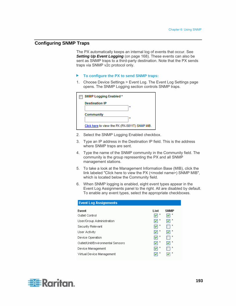
Chapter 6: Using SNMP
193
Configuring SNMP Traps
The PX automatically keeps an internal log of events that occur. See Setting Up Event Logging (on page 168). These events can also be sent as SNMP traps to a third-party destination. Note that the PX sends traps via SNMP v2c protocol only.
To configure the PX to send SNMP traps:
1. Choose Device Settings > Event Log. The Event Log Settings page opens. The SNMP Logging section controls SNMP traps.
2. Select the SNMP Logging Enabled checkbox.
3. Type an IP address in the Destination IP field. This is the address where SNMP traps are sent.
4. Type the name of the SNMP community in the Community field. The community is the group representing the PX and all SNMP management stations.
5. To take a look at the Management Information Base (MIB), click the link labeled "Click here to view the PX (<model name>) SNMP MIB", which is located below the Community field.
6. When SNMP logging is enabled, eight event types appear in the Event Log Assignments panel to the right. All are disabled by default. To enable any event types, select the appropriate checkboxes.

Chapter 6: Using SNMP
194
7. Click Apply.
8. Choose Maintenance > Unit Reset to reset the PX device. You must reset the PX after enabling SNMP logging or changing the Destination IP address. If not, traps are not sent to the specified Destination IP address.
Note: You should update the MIB used by your SNMP manager when upgrading to a new PX release. This ensures your SNMP manager has the correct MIB for the release you are using.
Suggestion for SNMP Trap Configuration
The PX web interface allows you to specify the SNMP destinations using two menu commands, which generate different types of SNMP traps as described in the table.
Menu command Trap type Protocol
Device Settings > Event Log ALL traps described in the MIB can be generated, including the ThresholdAlarm trap.
SNMP v2c
Alerts > Alert Destinations Only the ThresholdAlarm trap is generated. SNMP v2c
Therefore, when configuring the Alert policy for SNMP, it is highly recommended to choose Device Settings > Event Log, and then:
Select the SNMP Logging Enabled checkbox
Specify the SNMP destination on the Event Log Settings page only (instead of doing it on the Alert Destinations page)
SNMP Traps and Event Types
After selecting specific event types on the Event Log page, associated SNMP traps may be generated and sent to the assigned destination. This table shows all event types and the traps they are associated with.
Event type SNMP traps
Outlet Control powerControl
thresholdAlarm Outlet/Unit/Environmental Sensors
externalOnOffSensorStateChange
userAdded
userModified
userDeleted
groupAdded
User/Group Administration
groupModified
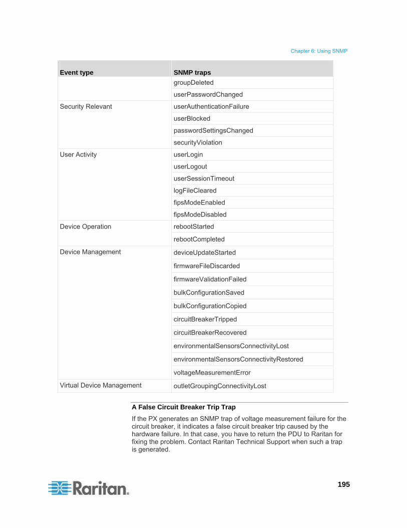
Chapter 6: Using SNMP
195
Event type SNMP traps
groupDeleted
userPasswordChanged
userAuthenticationFailure
userBlocked
passwordSettingsChanged
Security Relevant
securityViolation
userLogin
userLogout
userSessionTimeout
logFileCleared
fipsModeEnabled
User Activity
fipsModeDisabled
rebootStarted Device Operation
rebootCompleted
deviceUpdateStarted
firmwareFileDiscarded
firmwareValidationFailed
bulkConfigurationSaved
bulkConfigurationCopied
circuitBreakerTripped
circuitBreakerRecovered
environmentalSensorsConnectivityLost
environmentalSensorsConnectivityRestored
Device Management
voltageMeasurementError
Virtual Device Management outletGroupingConnectivityLost
A False Circuit Breaker Trip Trap
If the PX generates an SNMP trap of voltage measurement failure for the circuit breaker, it indicates a false circuit breaker trip caused by the hardware failure. In that case, you have to return the PDU to Raritan for fixing the problem. Contact Raritan Technical Support when such a trap is generated.

Chapter 6: Using SNMP
196
SNMP Gets and Sets
In addition to sending traps, the PX is able to receive SNMP get and set requests from third-party SNMP managers.
Get requests are used to retrieve information about the PX, such as the system location, and the current on a specific outlet.
Set requests are used to configure a subset of the information, such as the SNMP system name.
Note: The SNMP system name is the PX device name. When you change the SNMP system name, the device name shown in the web interface is also changed.
The PX does NOT support configuring IPv6-related parameters using the SNMP set requests.
Valid objects for these requests are limited to those found in the SNMP MIB-II System Group and the custom PX MIB.
You must target only one item at a time with SNMP set requests. Any attempt to configure multiple targets with a single set request results in all targets receiving the last assigned value. For example, if you use SNMP to set the status of Outlet 1 to ON and Outlet 4 to OFF, both Outlet 1 and Outlet 4 are set to OFF.
The PX MIB
This MIB is available via one of the following:
SNMP Settings page (Device Settings > SNMP Settings )
Event Log Settings page (Device Settings > Event Log)
Point your browser to http://<ip-address>/MIB.txt, where <ip-address> is the IP address of your PX
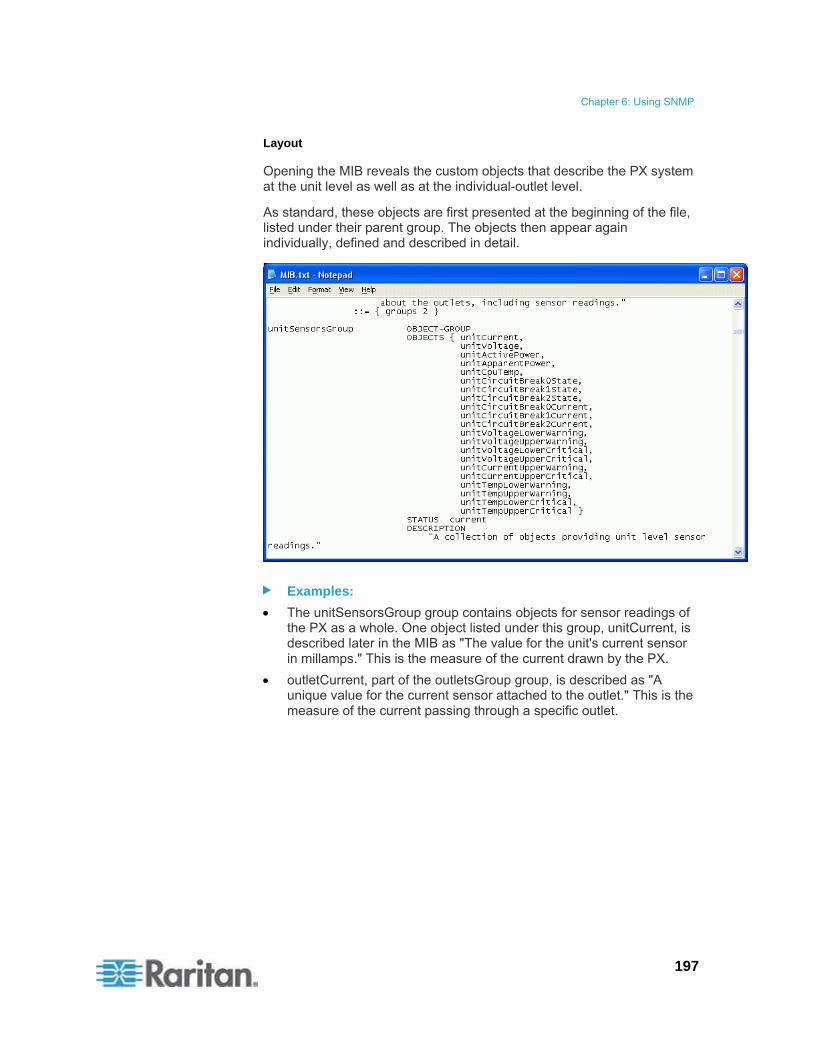
Chapter 6: Using SNMP
197
Layout
Opening the MIB reveals the custom objects that describe the PX system at the unit level as well as at the individual-outlet level.
As standard, these objects are first presented at the beginning of the file, listed under their parent group. The objects then appear again individually, defined and described in detail.
Examples:
The unitSensorsGroup group contains objects for sensor readings of the PX as a whole. One object listed under this group, unitCurrent, is described later in the MIB as "The value for the unit's current sensor in millamps." This is the measure of the current drawn by the PX.
outletCurrent, part of the outletsGroup group, is described as "A unique value for the current sensor attached to the outlet." This is the measure of the current passing through a specific outlet.

Chapter 6: Using SNMP
198
SNMP Sets and Configurable Objects
Some objects can be configured from the SNMP manager using SNMP set commands. Objects that can be configured have a MAX-ACCESS level of "read-write" in the MIB.
These objects include threshold objects, which cause the PX to generate a warning and send an SNMP trap when certain parameters are exceeded.
Note: When configuring the thresholds via SNMP set commands, ensure the value of upper critical threshold is higher than that of upper non-critical threshold. See Setting Up Power Thresholds and Hysteresis (on page 112) for information on thresholds.
Configuring the Hysteresis
You can configure the hysteresis values using the SNMP set command. Different from the PX web interface, SNMP accepts only integer values as the hysteresis values so decimal point values will be rejected.
To set a decimal point value, you must use the web interface to change the hysteresis values.
See A Note about Untriggered Alerts (on page 166) for a description of how a hysteresis value works.
Disabling Outlet Switching
Using the SNMP set command, you can enable or disable the outlet-switching capability of your PX. This feature is configurable through SNMP only. Firmware upgrade does not change this setting.
For any PX device not implemented with the outlet-switching capability, such as an in-line monitor, this feature cannot be configured via SNMP.
Refer to the PX MIB for more details.
Setting Data Retrieval
You can use the SNMP set command to configure the data retrieval-related settings.
Use "dataLogging" for enabling or disabling the data retrieval feature.
Use "dataLoggingInterval" or "measurementsPerLogEntry" for setting the sampling period.
The dataLoggingInterval (sampling period) is equal to the value of measurementsPerLogEntry times three. For example:
If measurementsPerLogEntry = 20, then dataLoggingInterval = 60 (20x3=60 seconds)

Chapter 6: Using SNMP
199
Tip: To use the web interface to configure the data retrieval-related settings, see Enabling Data Retrieval (on page 82). To adjust the Power IQ settings for optimal performance of the data retrieval feature, see Suggestions for Power IQ SNMP Settings (on page 262).
Retrieving Energy Usage
You can discover how much energy an IT device consumes by retrieving the Active Energy for the outlet this IT device is plugged into. An SNMP manager can send an SNMP get request for an outlet's outletWattHours value. The value returned is the number of WattHours consumed by the target outlet.
Configuring the FIPS Mode
The PX supports using the SNMP command to enable or disable the FIPS mode. Make sure you have downloaded the latest version of the MIB file to perform this function. See The PX MIB (on page 196).
To configure the FIPS mode via SNMP, you must:
Use SNMP v3 only to enable or disable the mode.
Use the admin account.
After enabling the FIPS mode, some security limitations are applied. See FIPS Limitations (on page 180) for details. The following lists the SNMP-related limitations in the FIPS mode.
The SNMP v1/v2c protocol is NOT supported, but the SNMP v3 protocol is still supported.
If the SNMP v3 protocol is enabled, the PX automatically forces the SNMP v3 encryption, which cannot be reset. After enabling this protocol, you must:
Enable the authentication and privacy to set the security level to authPriv.
Select SHA as the authentication algorithm.
Select AES as the privacy algorithm.
Note: MD5 and DES are NOT FIPS approved algorithms.

Chapter 6: Using SNMP
200
Configuring IPMI over LAN
The PX supports using the SNMP command to enable or disable IPMI over LAN. Make sure you have downloaded the latest version of the MIB file to perform this function. See The PX MIB (on page 196).
Note that the outlet grouping function may not work properly after disabling IPMI over LAN. See Outlet Grouping (on page 175).
To configure "IPMI over LAN" via SNMP:
SNMP v3 is strongly recommended.
Note: SNMP v2c may work but it is NOT recommended.
When using SNMP v3, only users belonging to the Admin user group are allowed to enable or disable IPMI over LAN.
If you have enabled SNMP v3, you MUST use SNMP v3 to configure "IPMI over LAN." That is, even though you have enabled both SNMP v2c and v3, you must use SNMP v3 instead of SNMP v2c.
Changing ID Numbers of Environmental Sensors
All ID numbers of existing environmental sensors can be rearranged at a time by using the SNMP MIB variable "reorderexternalSensorsTableEntries" and a comma-separated list.
Below are the guidelines of using this variable:
ID numbers of all managed sensors must be present in the list no matter their ID numbers will be changed or retained.
The list cannot contain more than 16 ID numbers, or it is discarded.
A valid ID number ranges between 1 to 16.
Each ID number in the list must be unique.
If there are missing numbers in the original ID numbers, indicate each missing number using a comma when changing ID numbers.
In order to avoid environmental sensor reordering anomalies, the user should configure his or her SNMP client to a sufficiently long timeout with no retries when issuing such a request.
Reset the PX after using the SNMP to reordering the environmental sensors. See Recommendation for Environmental Sensor Operations (on page 154).
Example without Missing Numbers
If you have five environmental sensors with the ID numbers 1, 2, 3, 4, and 5, and want to change the ID numbers as shown below:
1 to 13

Chapter 6: Using SNMP
201
2 to 8
3 to 9
4 remains unchanged
5 to 2
The original ID numbers are consecutive without any missing numbers so no additional commas should be added.
Position 1 2 3 4 5
Original ID numbers
1, 2, 3, 4, 5
New ID numbers
13, 8, 9, 4, 2
Therefore, your comma-separated list looks like the following:
13,8,9,4,2
Example with Missing Numbers
If you have five environmental sensors with the ID numbers 2, 5, 6, 7, 11, and want to change the ID numbers as shown below:
2 to 13
5 to 8
6 to 9
7 to 16
11 remains unchanged
Since the original ID numbers are inconsecutive because of missing numbers 1, 3, 4, 8, 9 and 10, you must mark each missing number with a comma in the comma-separated list.
Position 1 2 3 4 5 6 7 8 9 10 11
Original ID numbers
2, 5, 6, 7, 11
New ID numbers
, 13, , , 8, 9, 16, , , , 11
Therefore, your comma-separated list looks like the following:
,13,,,8,9,16,,,,11

Chapter 6: Using SNMP
202
A Note about Measurement Units
The measurement units for current and unit voltage vary depending on the type of SNMP operation.
Current:
SNMP get: Current values are measured in milliampere (mA).
SNMP set: Current values are measured in ampere (A).
Unit voltage:
SNMP get: Unit voltage is measured in volt (V).
SNMP set: Unit voltage is measured in millivolt (mV).
Retrieving and Interpreting Sensor Readings
You can use snmpget or snmpwalk commands to retrieve different environmental sensors' information. To interpret the sensor reading information retrieved via SNMP, you must apply the retrieved sensor information to the sensor reading formula shown below:
externalSensorValue / 10^ externalSensorDecimalDigits
To retrieve and interpret environmental sensor readings using SNMP commands:
1. Find out the sensor numbers by using the externalSensorTable OID 1.3.6.1.4.1.13742.4.3.3.1.1.
2. Retrieve the desired sensor's type using the externalSensorType OID 1.3.6.1.4.1.13742.4.3.3.1.2.
The OID syntax is
1.3.6.1.4.1.13742.4.3.3.1.2.<sensor ID>

Chapter 6: Using SNMP
203
3. Check the information of TypeOfSensorEnumeration to determine the sensor's type.
4. Retrieve the desired sensor's value using the externalSensorValue OID 1.3.6.1.4.1.13742.4.3.3.1.41.
The OID syntax is
1.3.6.1.4.1.13742.4.3.3.1.41.<sensor ID>
This retrieves an unscaled sensor value.
5. Retrieve the desired sensor's decimal digits using the externalSensorDecimalDigits OID 1.3.6.1.4.1.13742.4.3.3.1.17.
The OID syntax is
1.3.6.1.4.1.13742.4.3.3.1.17.<sensor ID>
This retrieves the scaling factor, which represents the number of digits displayed to the right of the decimal point.

Chapter 6: Using SNMP
204
6. Retrieve the desired sensor's measurement units using the externalSensorUnits OID 1.3.6.1.4.1.13742.4.3.3.1.16.
The OID syntax is
1.3.6.1.4.1.13742.4.3.3.1.16.<sensor ID>
7. Check the information of SensorUnitsEnumeration to determine the measurement unit of the reading.
8. Use the sensor reading formula to calculate the sensor readings.
Example
This section illustrates the retrieval and interpretation of a specific sensor's readings via SNMP commands.
If the ID number of the environmental sensor whose readings you want to retrieve is 3, follow the procedure below to get the readings.
1. Use OID 1.3.6.1.4.1.13742.4.3.3.1.2.3 to retrieve the sensor type value.
Assume the retrieved value is 10.
Chapter 6: Using SNMP
205
2. According to the information of TypeOfSensorEnumeration, 10 represents a temperature sensor.
3. Use OID 1.3.6.1.4.1.13742.4.3.3.1.41.3 to retrieve the sensor value.
Assume the retrieved value is 465.
4. Use OID 1.3.6.1.4.1.13742.4.3.3.1.17.3 to retrieve the sensor's decimal digit value.
Assume the retrieved value is 1.
5. Use OID 1.3.6.1.4.1.13742.4.3.3.1.16.3 to retrieve the sensor's measurement unit value.
Assume the retrieved value is 14.
6. According to the information of SensorUnitsEnumeration, 14 represents degreeF ( ).
7. Use the sensor reading formula to interpret the sensor readings as shown below.
465 / 10^1=46.5
206
This section explains how to use the Command Line Protocol (CLP) interface to administer a PX device.
In This Chapter
About the CLP Interface ........................................................................206 Logging in to the CLP interface .............................................................206 Showing Outlet Information ...................................................................209 Showing In-Depth Outlet Information ....................................................211 Switching an Outlet................................................................................213 Querying an Outlet Sensor ....................................................................214 Setting the Sequence Delay..................................................................214 Showing Environmental Sensor Information .........................................215 Configuring the Thresholds for Environmental Sensors........................219 Querying the PDU's Serial Number.......................................................220 Resetting the PX Device........................................................................220 Using the Help Command .....................................................................220
About the CLP Interface
The PX provides a command line interface that enables data center administrators to perform some basic management tasks.
The interface is based on the Systems Management Architecture for Server Hardware (SMASH) Command Line Protocol (CLP).
Using this interface, you can do the following:
Reset the PX device
Display the name, power state (on or off), and sensors associated with each outlet
Turn each outlet on or off
Display the status of the sensors associated with each outlet
You can access the interface over a local connection using a terminal emulation program such as HyperTerminal, or via a Telnet or SSH client such as PuTTY.
Note: Telnet access is disabled by default because it communicates openly and is thus insecure. To enable Telnet, see Modifying Network Service Settings (on page 74).
Logging in to the CLP interface
Logging in via HyperTerminal over a local connection is a little different than logging in using SSH or Telnet.
Chapter 7 Using the CLP Interface
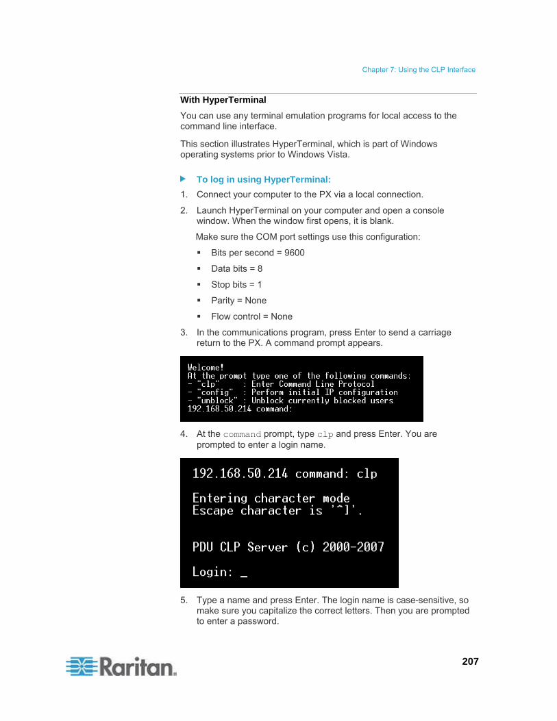
Chapter 7: Using the CLP Interface
207
With HyperTerminal
You can use any terminal emulation programs for local access to the command line interface.
This section illustrates HyperTerminal, which is part of Windows operating systems prior to Windows Vista.
To log in using HyperTerminal:
1. Connect your computer to the PX via a local connection.
2. Launch HyperTerminal on your computer and open a console window. When the window first opens, it is blank.
Make sure the COM port settings use this configuration:
Bits per second = 9600
Data bits = 8
Stop bits = 1
Parity = None
Flow control = None
3. In the communications program, press Enter to send a carriage return to the PX. A command prompt appears.
4. At the command prompt, type clp and press Enter. You are prompted to enter a login name.
5. Type a name and press Enter. The login name is case-sensitive, so make sure you capitalize the correct letters. Then you are prompted to enter a password.

Chapter 7: Using the CLP Interface
208
6. Type a password and press Enter. The password is case sensitive. After properly entering the password, the clp:/-> system prompt appears.
7. You are now logged in to the command line interface and can begin administering the PX.
With SSH or Telnet
You can remotely log in to the command line interface using an SSH or Telnet client, such as PuTTY.
Note: PuTTY is a free program you can download from the Internet. See PuTTY's documentation for details on configuration.
To log in using SSH or Telnet:
1. Ensure SSH or Telnet has been enabled. See Modifying Network Service Settings (on page 74).
2. Launch an SSH or Telnet client and open a console window. A login prompt appears.
3. Type a name and press Enter. The login name is case-sensitive, so make sure you capitalize the correct letters.
Note: If using the SSH client, the name must NOT exceed 25 characters. Otherwise, the login fails.

Chapter 7: Using the CLP Interface
209
Then you are prompted to enter a password.
4. Type a password and press Enter. The password is case sensitive. After properly entering the password, the clp:/-> system prompt appears.
5. You are now logged in to the command line interface and can begin administering the PX.
Closing a Local Connection
Close the window or terminal emulation program when you finish accessing a PX device over the local connection.
When accessing or upgrading multiple PX devices, do not transfer the local connection cable from one device to another without closing the local connection window first.
Showing Outlet Information
The show command displays the name, power state (on or off), and associated sensors for one outlet or for all outlets.
Note: When displaying outlet information, the outlet names are returned as OUTLET1, OUTLET2, and so on. The CLP interface does not reflect the names assigned to the outlets from the web interface.
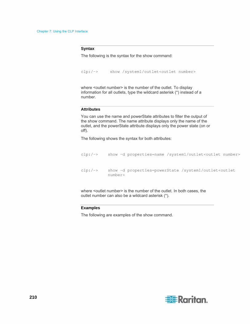
Chapter 7: Using the CLP Interface
210
Syntax
The following is the syntax for the show command:
clp:/-> show /system1/outlet<outlet number>
where <outlet number> is the number of the outlet. To display information for all outlets, type the wildcard asterisk (*) instead of a number.
Attributes
You can use the name and powerState attributes to filter the output of the show command. The name attribute displays only the name of the outlet, and the powerState attribute displays only the power state (on or off).
The following shows the syntax for both attributes:
clp:/-> show -d properties=name /system1/outlet<outlet number>
clp:/-> show -d properties=powerState /system1/outlet<outlet number>
where <outlet number> is the number of the outlet. In both cases, the outlet number can also be a wildcard asterisk (*).
Examples
The following are examples of the show command.

Chapter 7: Using the CLP Interface
211
Example 1 - No Attributes
The diagram shows the output of the show command without any attributes entered.
Example 2 - Name Attribute
The diagram shows the output of the show command with the name attribute.
Example 3 - powerState Attribute
The diagram shows the output of the show command with the powerState attribute.
Showing In-Depth Outlet Information
Use the show command to display the RMS Current, Power Factor, Max Current, Active Power and Apparent Power of a specific outlet.
To show in-depth outlet information:
1. Perform the show command on an outlet. This displays the sensors associated with the designated outlet.

Chapter 7: Using the CLP Interface
212
2. Perform the show command on sensors associated with the outlet.
Outlet Sensor Properties
When you perform the show command on an outlet sensor, several properties appear.
Name
Threshold state
Measurement taken by the sensor
The Name property identifies what a sensor measures.
If the name contains: The sensor measures:
Current RMS Current
PwrFactor Power Factor
Max Curr Maximum Current
Act. Power Active Power
Apt. Power Apparent Power
Active Energy Active Energy
Tip: Sometimes the OtherSensorTypeDescription property is also helpful for identifying the outlet sensor type.
Examples of Showing In-Depth Outlet Information
1. Perform the show command on the outlet without additional attributes.

Chapter 7: Using the CLP Interface
213
2. Perform the show command on the associated sensors.
Switching an Outlet
The set command can turn an outlet on or off.
Turning an Outlet On
Using the keyword on turns the outlet on.
clp:/-> set /system1/outlet<outlet number> powerState=on
where <outlet number> is the number of the outlet.
Turning an Outlet Off
Using the keyword off turns the outlet off.
clp:/-> set /system1/outlet<outlet number> powerState=off
where <outlet number> is the number of the outlet.
Chapter 7: Using the CLP Interface
214
Querying an Outlet Sensor
The show command with the keyword Antecedent queries an outlet's sensors.
clp:/-> show -d properties=Antecedent /system1/outlet<outlet number>=>CIM_AssociatedSensor
where <outlet number> is the number of the outlet.
Setting the Sequence Delay
The set command can change the sequence delay for all outlets.
clp:/-> set /system1 powerOnDelay=X
where X is in seconds.
For example, powerOnDelay=2 sets the sequence delay to 2 seconds, and powerOnDelay=10 sets the sequence delay to 10 seconds.
Tip: To set the sequence delay in "milliseconds," use the PX web interface. See Setting the Global Power Cycling Delay (on page 107).

Chapter 7: Using the CLP Interface
215
Showing Environmental Sensor Information
The following is the syntax for the show command for environmental sensors:
clp:/-> show /system1/externalsensor<ID number>
where <ID number> is the ID number assigned to the environmental sensor while having the environmental sensor managed. The maximum number is 16 since the PX device can manage up to 16 environmental sensors.
To display information for all environmental sensors, type the wildcard asterisk (*) instead of a number.
If the selected environmental sensor is a contact closure sensor, the PX shows it has three possible states -- OK, Transition to Active, and Transition to Idle.
OK = Normal. See "Normal" State (on page 150).
Transition to Active = Alarm. See "Alarm" State (on page 151).
The state of "Transition to Idle" is not used so it does not match any state shown in the PX web interface.
Identifying the Sensor Types
When you perform the show command for an environmental sensor, you can check the OtherSensorTypeDescription property to identify the sensor type.
If the property shows: Sensor type
Humidity Humidity sensor
Temperature Temperature sensor
Contact Contact closure sensor -- the detector connected to Raritan's contact closure sensor could be one of the following sensor types:
Third-party sensors for door open/closed status detection, door lock detection, vibration detection, floor water detection or smoke detection
Raritan's floor water sensors
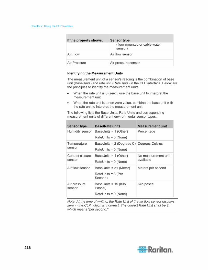
Chapter 7: Using the CLP Interface
216
If the property shows: Sensor type (floor-mounted or cable water sensor)
Air Flow Air flow sensor
Air Pressure Air pressure sensor
Identifying the Measurement Units
The measurement unit of a sensor's reading is the combination of base unit (BaseUnits) and rate unit (RateUnits) in the CLP interface. Below are the principles to identify the measurement units.
When the rate unit is 0 (zero), use the base unit to interpret the measurement unit.
When the rate unit is a non-zero value, combine the base unit with the rate unit to interpret the measurement unit.
The following lists the Base Units, Rate Units and corresponding measurement units of different environmental sensor types.
Sensor type Base/Rate units Measurement unit
Humidity sensor BaseUnits = 1 (Other)
RateUnits = 0 (None)
Percentage
Temperature sensor
BaseUnits = 2 (Degrees C)
RateUnits = 0 (None)
Degrees Celsius
Contact closure sensor
BaseUnits = 1 (Other)
RateUnits = 0 (None)
No measurement unit available
Air flow sensor BaseUnits = 31 (Meter)
RateUnits = 3 (Per Second)
Meters per second
Air pressure sensor
BaseUnits = 15 (Kilo Pascal)
RateUnits = 0 (None)
Kilo pascal
Note: At the time of writing, the Rate Unit of the air flow sensor displays zero in the CLP, which is incorrect. The correct Rate Unit shall be 3, which means "per second."

Chapter 7: Using the CLP Interface
217
Example 1 - No Attributes
This diagram shows the output of the show command without any attributes entered for a humidity sensor, whose ID number is 1.

Chapter 7: Using the CLP Interface
218
The diagram shows the output of the show command without any attributes entered for a contact closure sensor, whose ID number is 3.
Example 2 - Name Attribute
The diagram shows the output of the show command with the name attribute for the environmental sensor 1.
Example 3 - CurrentReading Attribute
The diagram shows the output of the show command with the CurrentReading attribute for the environmental sensor 1.
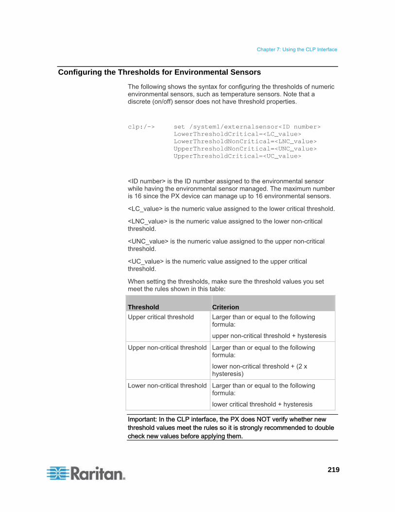
Chapter 7: Using the CLP Interface
219
Configuring the Thresholds for Environmental Sensors
The following shows the syntax for configuring the thresholds of numeric environmental sensors, such as temperature sensors. Note that a discrete (on/off) sensor does not have threshold properties.
clp:/-> set /system1/externalsensor<ID number> LowerThresholdCritical=<LC_value> LowerThresholdNonCritical=<LNC_value> UpperThresholdNonCritical=<UNC_value> UpperThresholdCritical=<UC_value>
<ID number> is the ID number assigned to the environmental sensor while having the environmental sensor managed. The maximum number is 16 since the PX device can manage up to 16 environmental sensors.
<LC_value> is the numeric value assigned to the lower critical threshold.
<LNC_value> is the numeric value assigned to the lower non-critical threshold.
<UNC_value> is the numeric value assigned to the upper non-critical threshold.
<UC_value> is the numeric value assigned to the upper critical threshold.
When setting the thresholds, make sure the threshold values you set meet the rules shown in this table:
Threshold Criterion
Upper critical threshold Larger than or equal to the following formula:
upper non-critical threshold + hysteresis
Upper non-critical threshold Larger than or equal to the following formula:
lower non-critical threshold + (2 x hysteresis)
Lower non-critical threshold Larger than or equal to the following formula:
lower critical threshold + hysteresis
Important: In the CLP interface, the PX does NOT verify whether new threshold values meet the rules so it is strongly recommended to double check new values before applying them.
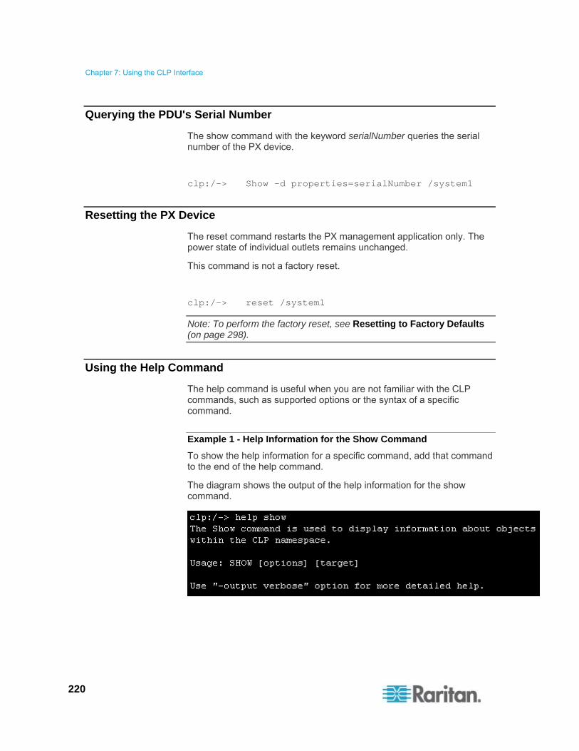
Chapter 7: Using the CLP Interface
220
Querying the PDU's Serial Number
The show command with the keyword serialNumber queries the serial number of the PX device.
clp:/-> Show -d properties=serialNumber /system1
Resetting the PX Device
The reset command restarts the PX management application only. The power state of individual outlets remains unchanged.
This command is not a factory reset.
clp:/-> reset /system1
Note: To perform the factory reset, see Resetting to Factory Defaults (on page 298).
Using the Help Command
The help command is useful when you are not familiar with the CLP commands, such as supported options or the syntax of a specific command.
Example 1 - Help Information for the Show Command
To show the help information for a specific command, add that command to the end of the help command.
The diagram shows the output of the help information for the show command.

Chapter 7: Using the CLP Interface
221
Example 2 - Getting In-Depth Help Information
To show detailed help information, add the option -output verbose between the help command and the queried command.
The diagram shows the output of the help information for the show command in details.

222
The model name of a PX in-line monitor follows this format: PX-3nnn, where n is a numeric digit.
Unlike most of the PX devices, an in-line monitor may have multiple inlets. Each inlet is connected to an outlet only, so an inlet's rating is the same as an outlet's rating.
Raritan provides both single-phase and three-phase in-line monitors to satisfy different needs.
In This Chapter
Overview................................................................................................222 Safety Instructions .................................................................................224 Flexible Cord Installation Instructions....................................................225 In-Line Monitor's LED Display ...............................................................234 In-line Monitor's Web Interface..............................................................235 SNMP and CLP Interfaces ....................................................................237
Overview
An in-line monitor is implemented with the same number of inlets and outlets. An inlet is connected to a power source for receiving electricity, such as electric distribution panels or branch circuit receptacles. An outlet is connected to a device that draws power, such as a cooling or IT device.
Inlets are located at the side labeled Line, and outlets are located at the side labeled Load.
Two types of mechanical designs are available for an in-line monitor's inlets and outlets:
Power-socket type, such as PX-3411
Cable-gland type, such as PX-3420
Chapter 8 In-line Monitors

Chapter 8: In-line Monitors
223
Models with Power Sockets
This diagram shows an in-line monitor whose inlets and outlets are in the form of power sockets or receptacles. The total number of inlets and outlets varies depending on the model you purchased.
Number Description
1 Inlets (the side labeled LINE)
2 Top cover
3 Outlets (the side labeled LOAD)
4 Front panel with the LED display
5 Rear panel
Models with Cable Glands
This diagram shows an in-line monitor whose inlets and outlets are in the form of cable glands. The total number of inlets and outlets varies depending on the model you purchased.
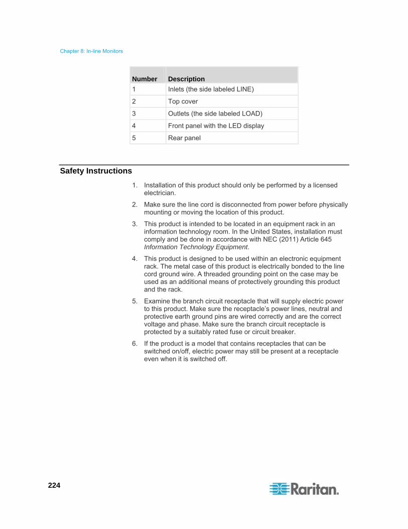
Chapter 8: In-line Monitors
224
Number Description
1 Inlets (the side labeled LINE)
2 Top cover
3 Outlets (the side labeled LOAD)
4 Front panel with the LED display
5 Rear panel
Safety Instructions
1. Installation of this product should only be performed by a licensed electrician.
2. Make sure the line cord is disconnected from power before physically mounting or moving the location of this product.
3. This product is intended to be located in an equipment rack in an information technology room. In the United States, installation must comply and be done in accordance with NEC (2011) Article 645 Information Technology Equipment.
4. This product is designed to be used within an electronic equipment rack. The metal case of this product is electrically bonded to the line cord ground wire. A threaded grounding point on the case may be used as an additional means of protectively grounding this product and the rack.
5. Examine the branch circuit receptacle that will supply electric power to this product. Make sure the receptacle’s power lines, neutral and protective earth ground pins are wired correctly and are the correct voltage and phase. Make sure the branch circuit receptacle is protected by a suitably rated fuse or circuit breaker.
6. If the product is a model that contains receptacles that can be switched on/off, electric power may still be present at a receptacle even when it is switched off.
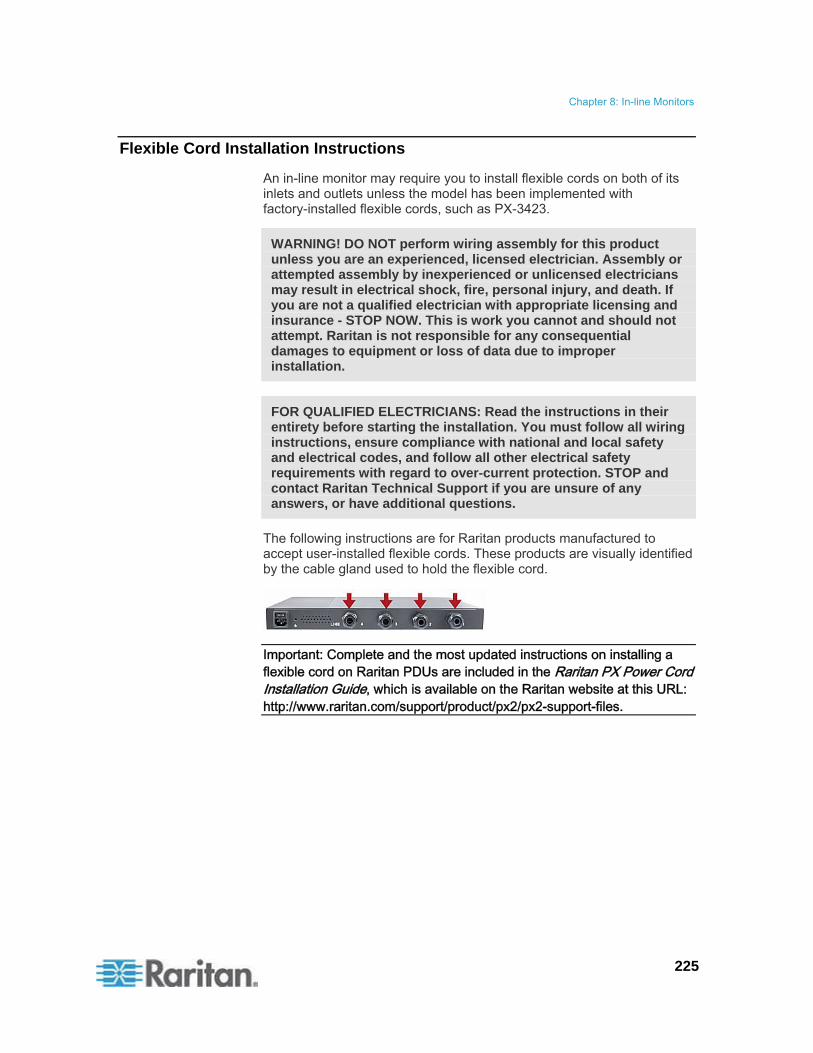
Chapter 8: In-line Monitors
225
Flexible Cord Installation Instructions
An in-line monitor may require you to install flexible cords on both of its inlets and outlets unless the model has been implemented with factory-installed flexible cords, such as PX-3423.
WARNING! DO NOT perform wiring assembly for this product unless you are an experienced, licensed electrician. Assembly or attempted assembly by inexperienced or unlicensed electricians may result in electrical shock, fire, personal injury, and death. If you are not a qualified electrician with appropriate licensing and insurance - STOP NOW. This is work you cannot and should not attempt. Raritan is not responsible for any consequential damages to equipment or loss of data due to improper installation.
FOR QUALIFIED ELECTRICIANS: Read the instructions in their entirety before starting the installation. You must follow all wiring instructions, ensure compliance with national and local safety and electrical codes, and follow all other electrical safety requirements with regard to over-current protection. STOP and contact Raritan Technical Support if you are unsure of any answers, or have additional questions.
The following instructions are for Raritan products manufactured to accept user-installed flexible cords. These products are visually identified by the cable gland used to hold the flexible cord.
Important: Complete and the most updated instructions on installing a flexible cord on Raritan PDUs are included in the Raritan PX Power Cord Installation Guide, which is available on the Raritan website at this URL: http://www.raritan.com/support/product/px2/px2-support-files.

Chapter 8: In-line Monitors
226
Flexible Cord Selection
The preferred flexible cable is type SOOW, 600V, 90°C or 105°C. Consult Raritan before using a different flexible cable type.
The rated ampacity of the flexible cord must be greater than or equal to the Raritan product’s rated ampacity marked on its nameplate. In the United States, relevant ampacity ratings for flexible cords can be found in NEC(2011) section 400.5.
The number of wires in the flexible cord must match the number of terminals (including the ground terminal) inside the Raritan product. See Wiring of 3-Phase In-Line Monitors (on page 227) for exceptions.
If a plug is to be attached to the flexible cord, the length of the flexible cord must not exceed 4.5 meters - as specified in UL 60950-1 (2007) and NEC 645.5 (2011).
The flexible cord may be permanently connected to power subject to local regulatory agency approval. In the United States, relevant electrical regulations can be found in NEC (2011) sections 400.7(A)(8), 400.7(B), 368.56 and table 400.4.
Plug Selection
If a plug is to be attached to the flexible cord, the plug’s rated ampacity is chosen as follows:
In the United States, as specified in UL 60950-1, the plug’s rated ampacity must be 125% greater than the Raritan product’s rated ampacity. In some Raritan products, such as 35A 3-phase delta wired PDUs, an exactly 125% rated plug is not available. In these cases, choose the closest plug that is more than 125%. For example, a 50A plug is the closest fit for a 35A 3-phase PDU.
For all other locations, subject to local regulatory agency policy, the plug’s rated ampacity is the same as the Raritan products rated ampacity.
Derating a Raritan Product
Lower rated plugs, receptacles and flexible cords may be connected to a Raritan product. This results in a derated (reduced) ampacity rating for the product.
Derating guidelines:
1. Choose the plug and use its rated ampacity to determine the derated ampacity.
In the United States, as specified in UL 60950-1, the derated ampacity is 80% of the plug’s rated ampacity. For example, a 30A plug would result in a derated ampacity of 24A.

Chapter 8: In-line Monitors
227
In other geographic locations, subject to local regulatory agency approval, the derated ampacity is the plug’s rated ampacity. For example, using a 16A plug would result in a derated ampacity of 16A.
2. The derated ampacity must be marked on the Raritan product so the new reduced rating can be easily identified.
3. For in-line monitors, the receptacles used must have the same voltage and ampacity rating as the plug chosen in step 1.
4. The flexible cord must have a rated ampacity greater than or equal to the derated ampacity. Since the new flexible cord may be smaller diameter, a check must be performed to insure the cable gland nut, when tightened, will securely hold the flexible cord so that it cannot be twisted, pulled or pushed in the cable gland. A sealing ring, for small diameter flexible cords, may have been included with the Raritan product, or one can be requested from Raritan, to reduce the inside diameter of the cable gland.
Receptacle Selection
For Raritan in-line monitors, any receptacle fitted to the outlet flexible cord must have identical ratings as the plug attached to the inlet flexible cord.
Wiring of 3-Phase In-Line Monitors
3-phase in-line monitors contain 4-pole wiring terminal blocks (L1, L2, L3, N) to monitor 5-wire (4P+PE) 3-phase wye connections. Delta wired 4-wire (3P+PE) 3-phase connections are also permitted (no wire connected to the terminal block neutral “N”). No additional hardware or firmware configuration is required to specify whether the connection is 5-wire wye or 4-wire delta.
In-Line Monitor Unused Channels
It is not necessary to wire up all channels of multi-channel in-line monitors. The inlet and outlet openings of unused channels must be completely closed off. “Goof plugs” for this purpose may be a good choice if they are available in your country or region.

Chapter 8: In-line Monitors
228
Step by Step Flexible Cord Installation
The following items are required to complete the installation:
Flexible cord(s).
Insulated ring terminals (one for each wire) and appropriate crimp tool.
Plug(s) and receptacle(s) (for in-line monitors)
Torque screwdriver, torque nut driver and torque wrench to tighten the wiring terminal block screws, ground nut and cable gland nut.
To install a flexible cord:
1. Open the PDU's access panel (or in-line monitor top panel) to expose the power wiring terminal block(s).

Chapter 8: In-line Monitors
229
One-channel in-line monitor
Zero U PDU
Make sure to locate the ground wire mounting stud(s). There is a separate ground wire mounting stud for each terminal block. Each flexible cord MUST have its green (or green/yellow) ground wire bonded to a ground wire mounting stud.

Chapter 8: In-line Monitors
230
For in-line monitors, make sure to identify the inlet terminal blocks (rear of monitor) and outlet terminal blocks (front of monitor). Each inlet terminal block has a corresponding outlet terminal block.
Number Description
Inlets (labeled LINE)
Outlets (labeled LOAD)
2. Strip off the outer jacket of the flexible cord and remove any jute, paper or other fillers. Use the following to help determine how much jacket to remove:
In the finished assembly, the outer jacket should protrude inside the Raritan product.
The wires will have ring terminals crimped onto them.
In the finished assembly, the wires should have some slack and not be taught.
In the finished assembly, if the flexible cord slips in the cable gland placing a strain on the cord’s wires, the ground wire must be the last wire to take the strain.
3. Crimp an insulated ring terminal onto each wire. A non-insulated ring terminal may be used for the ground wire. Inspect each crimp to insure it is secure and verify no exposed wire protrudes from the rear of an insulated ring terminal.
4. Loosen the cable gland nut and push the flexible cord assembly through the gland.

Chapter 8: In-line Monitors
231
Temporarily hand tighten the gland nut and verify the cord cannot be twisted or pushed or pulled in the gland. Do not proceed if hand tightening results in a loose cord. In some models, especially in-line monitors, the flexible cord’s diameter may be too small for the cable gland. A sealing ring for smaller diameter line cords may have been included with the Raritan product, or can be requested from Raritan, to reduce the inside diameter of the cable gland.
5. Fasten the ring terminal of the green (or green/yellow) ground wire to the chassis’s threaded ground stud in this order:
a. Place the lock washer on the stud.
b. Place the ground wire ring terminal on the stud.
c. Place the nut on the stud and tighten with a torque wrench. The appropriate torque settings vary according to the nut size.
Nut size Torque setting (N·m)
Tolerance
M3 0.49 10%
M4 1.27 8%
M5 1.96 5%
M6 2.94 3.5%
M8 4.9 2%
d. Check the ground wire connection. It should be secure and not move or rotate.

Chapter 8: In-line Monitors
232
6. Fasten the ring terminals of all remaining wires to the terminal block and tighten each using a torque screwdriver. The appropriate torque settings vary according to the screw size.
Screw size Torque setting (N·m)
Tolerance
M3 0.49 10%
M4 1.27 8%
M5 1.96 5%
M6 2.94 3.5%
M8 4.9 2%
Make sure each ring terminal is firmly fastened and cannot be twisted by hand. Use the following guidelines to help terminal block wiring.
In single-phase Raritan products with world-wide ratings, the terminals are labeled L1 and L2. L1 is the phase wire. L2 is either the neutral (120/230V installations) or another phase wire (208V installations).
In all 3-phase products, L1 is phase A, L2 is phase B, L3 is phase C and N is neutral.
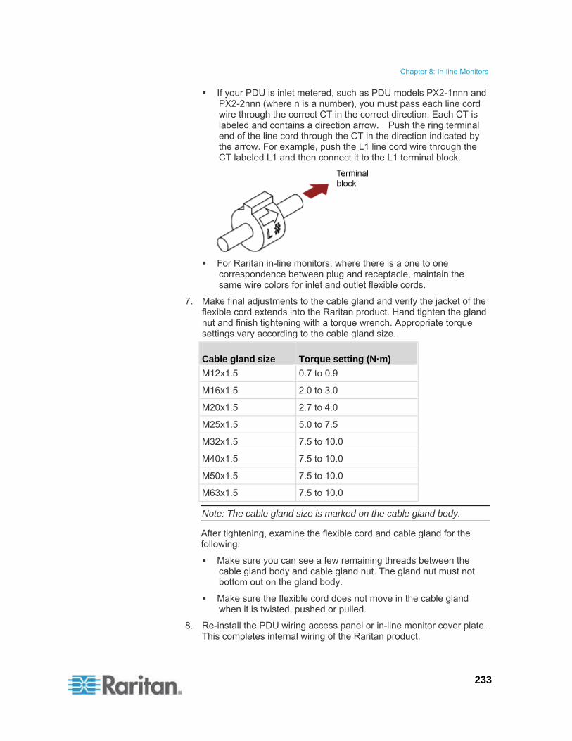
Chapter 8: In-line Monitors
233
If your PDU is inlet metered, such as PDU models PX2-1nnn and PX2-2nnn (where n is a number), you must pass each line cord wire through the correct CT in the correct direction. Each CT is labeled and contains a direction arrow. Push the ring terminal end of the line cord through the CT in the direction indicated by the arrow. For example, push the L1 line cord wire through the CT labeled L1 and then connect it to the L1 terminal block.
For Raritan in-line monitors, where there is a one to one correspondence between plug and receptacle, maintain the same wire colors for inlet and outlet flexible cords.
7. Make final adjustments to the cable gland and verify the jacket of the flexible cord extends into the Raritan product. Hand tighten the gland nut and finish tightening with a torque wrench. Appropriate torque settings vary according to the cable gland size.
Cable gland size Torque setting (N·m)
M12x1.5 0.7 to 0.9
M16x1.5 2.0 to 3.0
M20x1.5 2.7 to 4.0
M25x1.5 5.0 to 7.5
M32x1.5 7.5 to 10.0
M40x1.5 7.5 to 10.0
M50x1.5 7.5 to 10.0
M63x1.5 7.5 to 10.0
Note: The cable gland size is marked on the cable gland body.
After tightening, examine the flexible cord and cable gland for the following:
Make sure you can see a few remaining threads between the cable gland body and cable gland nut. The gland nut must not bottom out on the gland body.
Make sure the flexible cord does not move in the cable gland when it is twisted, pushed or pulled.
8. Re-install the PDU wiring access panel or in-line monitor cover plate. This completes internal wiring of the Raritan product.

Chapter 8: In-line Monitors
234
9. For in-line monitors, fasten the receptacles to the outlet flexible cords following the manufacturer’s instructions.
10. Complete the wiring of the inlet flexible cord by performing one of these steps:
Assemble the plug following the manufacturer’s instructions.
Permanently attach and strain relief the flexible cord to a junction box following applicable electrical codes.
In-Line Monitor's LED Display
The LED display of an in-line monitor is the same as a regular PX model. See LED Display (on page 47).
Automatic Mode
Unlike regular PX models, the in-line monitor's LED display only cycles through the current readings of each outlet in the Automatic Mode.
Manual Mode
You can switch between voltage, active power and current readings of the selected outlet in the Manual Mode on an in-line monitor. To enter the Manual Mode, press the Up or Down button.
To operate the LED display of an in-line monitor:
1. Press the Up or Down button until the desired outlet number is selected in the two-digit row.
Pressing the Up button moves up one selection.
Pressing the Down button moves down one selection.
2. Current of the selected outlet is shown in the three-digit row. It appears in this format: XX.X (A).
3. If desired, you can press the Up and Down buttons simultaneously to switch between current and voltage readings.
The voltage appears in this format: XXX (V). It is displayed for about five seconds, after which the current reading re-appears.
4. To switch to the active power readings, press the Up or Down button until the unbalanced load is selected in the two-digit row, such as 1U. Then press Up and Down buttons simultaneously to switch to the active power mode, such as 1P. Now you can press the Up or Down button to switch between the active power of different outlets/inlets.
The active power appears in this format: X.XX (W). It is displayed for about five seconds, after which the current reading re-appears.

Chapter 8: In-line Monitors
235
To exit from the active power mode, do NOT press any button until the LED display returns to the Automatic Mode.
Note: The LED display returns to the Automatic Mode after 10 seconds elapse since the last time any button was pressed.
Tip: A quick way to distinguish between voltage, current, and power is the placement of the decimal point in the display. Voltage has no decimal point, active power has a decimal point between the first and second digits, and current has a decimal point between the second and third digits.
In-line Monitor's Web Interface
An in-line monitor's web interface is similar to a regular PX model's web interface.
See Using the Web Interface (on page 54) for login instructions and additional information.
Menus
An in-line monitor is NOT implemented with the overcurrent protection mechanism and outlet-switching function, so its menu commands are slightly different from those of a regular PX PDU. The following list shows each menu with their own set of menu commands.
Details
Outlet Details
PDU Details
Outlet Setup
Alerts
Alert Configuration
Alert Policies
Alert Policy Editor
Alert Destinations
User Management
Change Password
Users & Groups
User/Group System Permissions

Chapter 8: In-line Monitors
236
Device Settings
PDU Setup
Network
Security
Certificate
Date/Time
Authentication
SMTP Settings
SNMP Settings
Event Log
FIPS Setting
External Sensors
External Sensors Details
External Sensors Setup
Maintenance
Device Information
View Event Log
Update Firmware
Bulk Configuration
Unit Reset
Diagnostics
Network Interface
Network Statistics
Ping Host
Trace Route to Host
Device Diagnostics
Help
About PX
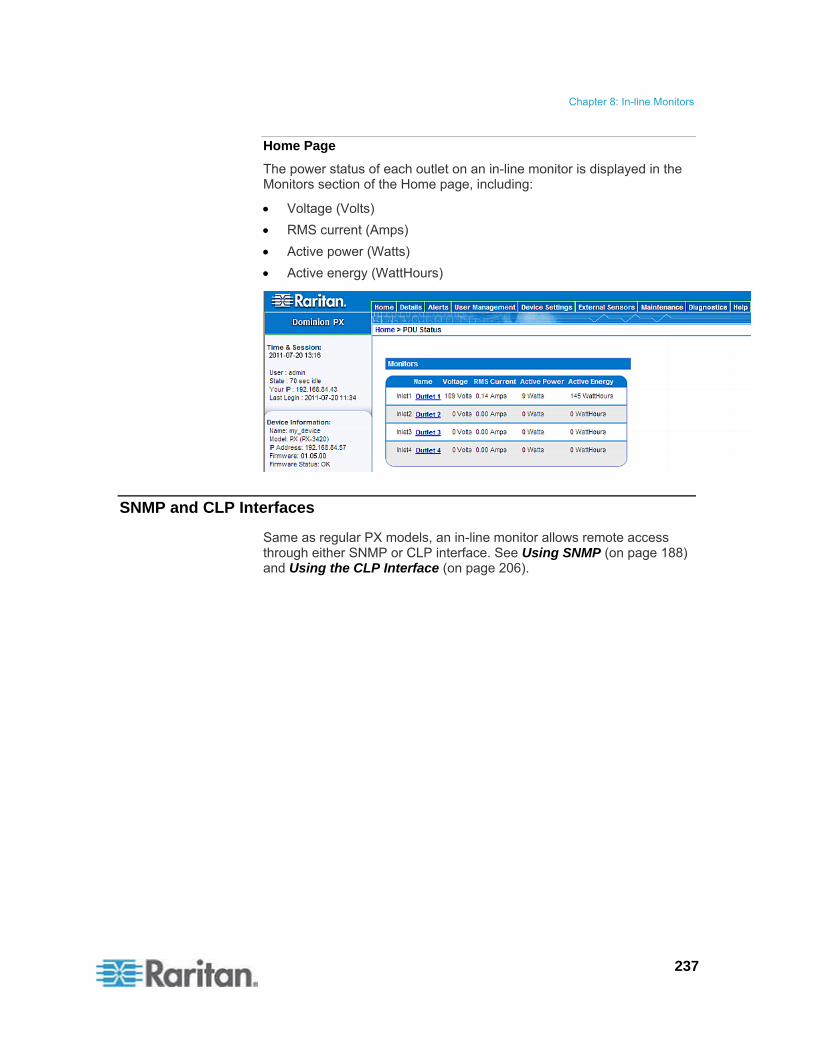
Chapter 8: In-line Monitors
237
Home Page
The power status of each outlet on an in-line monitor is displayed in the Monitors section of the Home page, including:
Voltage (Volts)
RMS current (Amps)
Active power (Watts)
Active energy (WattHours)
SNMP and CLP Interfaces
Same as regular PX models, an in-line monitor allows remote access through either SNMP or CLP interface. See Using SNMP (on page 188) and Using the CLP Interface (on page 206).
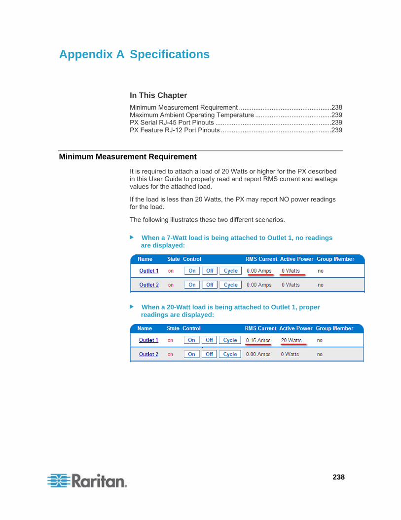
238
In This Chapter
Minimum Measurement Requirement ...................................................238 Maximum Ambient Operating Temperature ..........................................239 PX Serial RJ-45 Port Pinouts ................................................................239 PX Feature RJ-12 Port Pinouts .............................................................239
Minimum Measurement Requirement
It is required to attach a load of 20 Watts or higher for the PX described in this User Guide to properly read and report RMS current and wattage values for the attached load.
If the load is less than 20 Watts, the PX may report NO power readings for the load.
The following illustrates these two different scenarios.
When a 7-Watt load is being attached to Outlet 1, no readings are displayed:
When a 20-Watt load is being attached to Outlet 1, proper readings are displayed:
Appendix A Specifications

Appendix A: Specifications
239
Maximum Ambient Operating Temperature
The maximum ambient operating temperature (TMA) for the PX varies between 40 to 60 degrees Celsius, depending on the model and certification standard (CE or UL). If necessary, contact Raritan Technical Support for this information for your model.
Specification Measure
Max Ambient Temperature 40 to 60 degrees Celsius
PX Serial RJ-45 Port Pinouts
RJ-45 Pin/signal definition
Pin No. Signal Direction Description
1 DTR Output Reserved
2 GND ― Signal Ground
3 +5V ― Power for CIM
(200mA, fuse protected)
Warning: Pin 3 is only intended for use with Raritan devices.
4 TxD Output Transmit Data (Data out)
5 RxD Input Receive Data (Data in)
6 N/C N/C No Connection
7 GND ― Signal Ground
8 DCD Input Reserved
PX Feature RJ-12 Port Pinouts
RJ-12 Pin/signal definition
Pin No. Signal Direction Description
1 +12V ― Power
(500mA, fuse protected)

Appendix A: Specifications
240
RJ-12 Pin/signal definition
2 GND ― Signal Ground
3 RS485 (Data +)
bi-directional
Data Line +
4 RS485
(Data -)
bi-directional
Data Line -
5 GND ― Signal Ground
6 1-wire Used for Feature Port
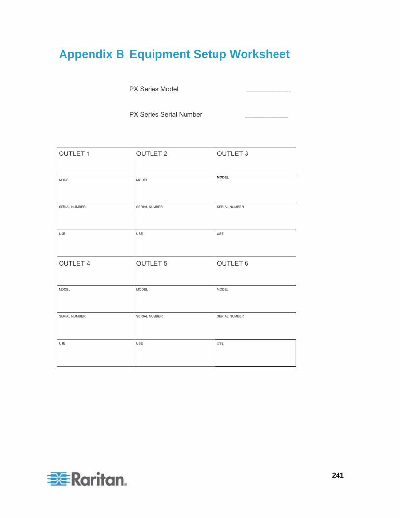
241
PX Series Model ____________
PX Series Serial Number ____________
OUTLET 1
OUTLET 2 OUTLET 3
MODEL
MODEL MODEL
SERIAL NUMBER
SERIAL NUMBER SERIAL NUMBER
USE
USE USE
OUTLET 4
OUTLET 5 OUTLET 6
MODEL
MODEL MODEL
SERIAL NUMBER
SERIAL NUMBER SERIAL NUMBER
USE
USE USE
Appendix B Equipment Setup Worksheet
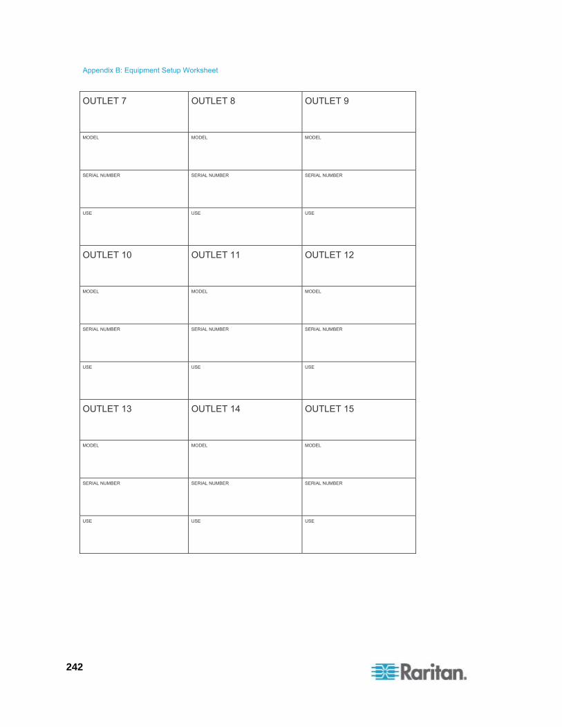
Appendix B: Equipment Setup Worksheet
242
OUTLET 7
OUTLET 8 OUTLET 9
MODEL
MODEL MODEL
SERIAL NUMBER
SERIAL NUMBER SERIAL NUMBER
USE
USE USE
OUTLET 10
OUTLET 11 OUTLET 12
MODEL
MODEL MODEL
SERIAL NUMBER
SERIAL NUMBER SERIAL NUMBER
USE
USE USE
OUTLET 13
OUTLET 14 OUTLET 15
MODEL
MODEL MODEL
SERIAL NUMBER
SERIAL NUMBER SERIAL NUMBER
USE
USE USE

Appendix B: Equipment Setup Worksheet
243
OUTLET 16
OUTLET 17 OUTLET 18
MODEL
MODEL MODEL
SERIAL NUMBER
SERIAL NUMBER SERIAL NUMBER
USE
USE USE
OUTLET 19
OUTLET 20 OUTLET 21
MODEL
MODEL MODEL
SERIAL NUMBER
SERIAL NUMBER SERIAL NUMBER
USE
USE USE

Appendix B: Equipment Setup Worksheet
244
OUTLET 22
OUTLET 23 OUTLET 24
MODEL
MODEL MODEL
SERIAL NUMBER
SERIAL NUMBER SERIAL NUMBER
USE
USE USE
Types of adapters
_________________________________________________________
Types of cables
_________________________________________________________
Name of software program
_________________________________________________________
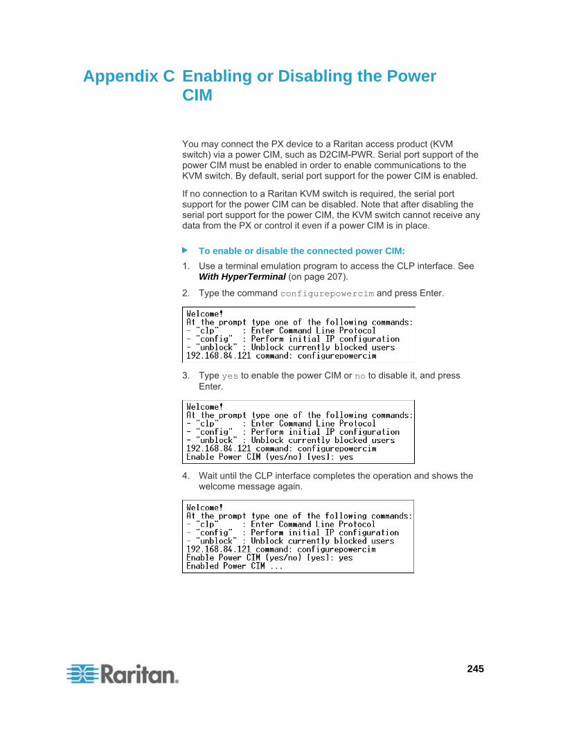
245
You may connect the PX device to a Raritan access product (KVM switch) via a power CIM, such as D2CIM-PWR. Serial port support of the power CIM must be enabled in order to enable communications to the KVM switch. By default, serial port support for the power CIM is enabled.
If no connection to a Raritan KVM switch is required, the serial port support for the power CIM can be disabled. Note that after disabling the serial port support for the power CIM, the KVM switch cannot receive any data from the PX or control it even if a power CIM is in place.
To enable or disable the connected power CIM:
1. Use a terminal emulation program to access the CLP interface. See With HyperTerminal (on page 207).
2. Type the command configurepowercim and press Enter.
3. Type yes to enable the power CIM or no to disable it, and press Enter.
4. Wait until the CLP interface completes the operation and shows the welcome message again.
Appendix C Enabling or Disabling the Power CIM
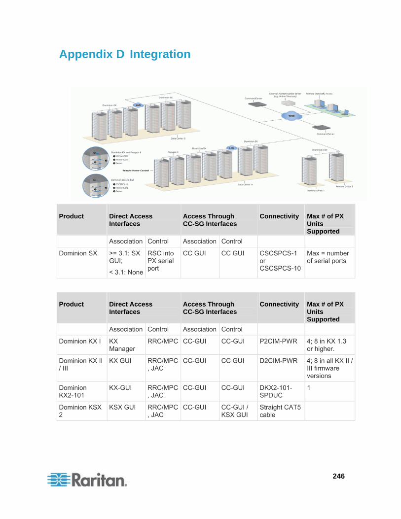
246
Product Direct Access Interfaces
Access Through CC-SG Interfaces
Connectivity Max # of PX Units Supported
Association Control Association Control
Dominion SX >= 3.1: SX GUI;
< 3.1: None
RSC into PX serial port
CC GUI CC GUI CSCSPCS-1 or CSCSPCS-10
Max = number of serial ports
Product Direct Access Interfaces
Access Through CC-SG Interfaces
Connectivity Max # of PX Units Supported
Association Control Association Control
Dominion KX I KX Manager
RRC/MPC CC-GUI CC-GUI P2CIM-PWR 4; 8 in KX 1.3 or higher.
Dominion KX II / III
KX GUI RRC/MPC, JAC
CC-GUI CC GUI D2CIM-PWR 4; 8 in all KX II / III firmware versions
Dominion KX2-101
KX-GUI RRC/MPC, JAC
CC-GUI CC-GUI DKX2-101- SPDUC
1
Dominion KSX 2
KSX GUI RRC/MPC, JAC
CC-GUI CC-GUI / KSX GUI
Straight CAT5 cable
Appendix D Integration
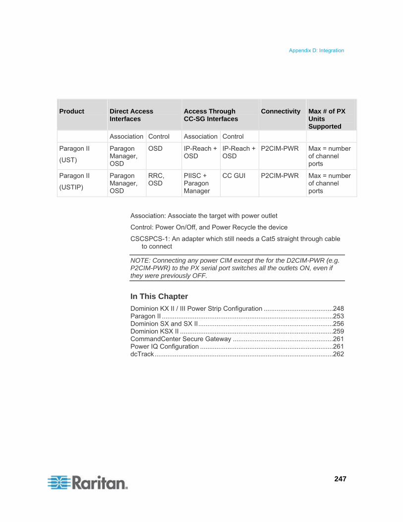
Appendix D: Integration
247
Product Direct Access Interfaces
Access Through CC-SG Interfaces
Connectivity Max # of PX Units Supported
Association Control Association Control
Paragon II
(UST)
Paragon Manager, OSD
OSD IP-Reach + OSD
IP-Reach + OSD
P2CIM-PWR Max = number of channel ports
Paragon II
(USTIP)
Paragon Manager, OSD
RRC, OSD
PIISC + Paragon Manager
CC GUI P2CIM-PWR Max = number of channel ports
Association: Associate the target with power outlet
Control: Power On/Off, and Power Recycle the device
CSCSPCS-1: An adapter which still needs a Cat5 straight through cable to connect
NOTE: Connecting any power CIM except the for the D2CIM-PWR (e.g. P2CIM-PWR) to the PX serial port switches all the outlets ON, even if they were previously OFF.
In This Chapter
Dominion KX II / III Power Strip Configuration ......................................248 Paragon II ..............................................................................................253 Dominion SX and SX II..........................................................................256 Dominion KSX II ....................................................................................259 CommandCenter Secure Gateway .......................................................261 Power IQ Configuration .........................................................................261 dcTrack..................................................................................................262

Appendix D: Integration
248
Dominion KX II / III Power Strip Configuration
Dominion KX II or KX III integration requires D2CIM-PWR and straight CAT5 cable.
For more information on KX II / III, refer to:
KX II or KX III User Guide on the Support page (http://www.raritan.com/support/)
KX II or KX III Online Help on the Product Online Help page (http://www.raritan.com/support/online-help/)
Note: For documentation conveniences, both Dominion KX II and KX III products are referred to as "KX III" in the following sections.
Configuring Rack PDU Targets
KX III allows you to connect rack PDUs (power strips) to KX III ports.
KX III rack PDU configuration is done from the KX III Port Configuration page.
Note: Raritan recommends no more than eight (8) rack PDUs (power strips) be connected to a KX III at once since performance may be affected.
Connecting a PX PDU
Raritan PX series rack PDUs (power strips) are connected to the Dominion device using the D2CIM-PWR CIM.
To connect the rack PDU:
1. Connect the male RJ-45 of the D2CIM-PWR to the female RJ-45 "SERIAL" port of the rack PDU.
2. Connect the female RJ-45 connector of the D2CIM-PWR to any of the available female system port connectors on the KX II / III using a straight through Cat5 cable.
3. Attach an AC power cord to the target server and an available rack PDU outlet.
4. Connect the rack PDU to an AC power source.

Appendix D: Integration
249
5. Power on the device.
Diagram key
PX rack PDU
D2CIM-PWR
KX II / III
D2CIM-PWR to rack PDU connection
D2CIM-PWR to KX II / III target device port via Cat5 cable

Appendix D: Integration
250
Naming the Rack PDU (Port Page for Power Strips)
Note: PX rack PDUs (power strips) can be named in the PX as well as in the KX III.
Once a Raritan remote rack PDU is connected to the KX III, it will appear on the Port Configuration page. Click on the power port name on that page to access it. The Type and the Name fields are prepopulated.
Note: The (CIM) Type cannot be changed.
The following information is displayed for each outlet on the rack PDU: [Outlet] Number, Name, and Port Association.
Use this page to name the rack PDU and its outlets. Names can be up to 32 alphanumeric characters and can include special characters.
Note: When a rack PDU is associated with a target server (port), the outlet name is replaced by the target server name, even if you assigned another name to the outlet.
To name the rack PDU and outlets:
Note: CommandCenter Secure Gateway does not recognize rack PDU names containing spaces.
1. Enter the Name of the rack PDU (if needed).
2. Change the [Outlet] Name if desired. (Outlet names default to the outlet #.)

Appendix D: Integration
251
3. Click OK.

Appendix D: Integration
252
Associating Outlets with Target Devices
The Port page opens when you click on a port on the Port Configuration page.
If an outlet is connected to the same server that the port is connected to, a power association can be made with the target device.
A server can have up to four power plugs and you can associate a different rack PDU (power strip) with each. From this page, you can define those associations so that you can power on, power off, and power cycle the server from the Port Access page.
To use this feature, you will need:
Raritan remote rack PDU(s)
Power CIMs (D2CIM-PWR)
Make a Power Association
To make power associations (associate rack PDU outlets to KVM target servers):
Note: When a rack PDU is associated to a target server (port), the outlet name is replaced by the target server name (even if you assigned another name to the outlet).
1. On the Port Configuration page, select the target server you are associating the PDU with.
2. Choose the rack PDU from the Power Strip Name drop-down list.
3. For that rack PDU, choose the outlet from the Outlet Name drop-down list.
4. Repeat steps 1 and 2 for all desired power associations.
5. Click OK. A confirmation message is displayed.
Turning Outlets On/Off and Cycling Power
To turn an outlet on:
1. Click the Power menu to access the Powerstrip page.
2. From the Powerstrip drop-down, select the PX rack PDU (power strip) you want to turn on.
3. Click Refresh to view the power controls.
4. Click On next to the outlet you want to power on.
5. Click OK to close the Power On confirmation dialog. The outlet will be turned on and its state will be displayed as 'on'.

Appendix D: Integration
253
To turn an outlet off:
1. Click Off next to the outlet you want to power off.
2. Click OK on the Power Off dialog.
3. Click OK on the Power Off confirmation dialog. The outlet will be turned off and its state will be displayed as 'off'.
To cycle the power of an outlet:
1. Click Cycle next to the outlet you want to cycle. The Power Cycle Port dialog opens.
2. Click OK. The outlet will then cycle (note that this may take a few seconds).
3. Once the cycling is complete the dialog will open. Click OK to close the dialog.
Paragon II
Paragon II integration requires P2CIM-PWR and straight CAT5 cable. You can associate up to four outlets to a target server, and all four outlets can be from separate PX devices, if necessary.
For more information on Paragon II, see either of the following:
Paragon II User Guide: Available on the Raritan website's Support page (http://www.raritan.com/support/).
Paragon II Online Help: Available on the Product Online Help page (http://www.raritan.com/support/online-help/).

Appendix D: Integration
254
Adding a PX in Paragon II
Add a PX device exactly as you would add any second-tier device. Your Paragon II auto-detects the PX device and changes the device type to PCR8, PCS12, PCS20, DPX16, or DPX24. On the OSD screen, press F5 to enter the Channel Configuration page. Select the channel and change the channel name from the default name to an identifying name for the PX device.
Associating Outlets with a Target Server
On the OSD screen, press the F5 key to enter the Channel Configuration page and select the channel. Press G to enter the Outlet Configuration page, and associate each outlet with appropriate IT devices.

Appendix D: Integration
255
Controlling a Target Server's Power
After associating the outlets with target servers, you can turn on, turn off or power cycle a target by controlling the outlets.
To control a target server's power:
1. Select a target server from the Selection Menu or Selection Menu by Name page, and press F3 to control power.
If no outlets are associated with the server, the message "No Outlets / Access Denied" appears.
If no permissions to outlets associated with the server exist, the message "No Outlets / Access Denied" appears.
Paragon automatically switches to the channel, so that the server is displayed in the background. If the switch fails, the message Switch fail appears.
If the switch is successful, all outlets associated with the server are displayed and so are the following power control options.
- Power Off (X)
- Power On (O)
- Recycle Power (R)
- Select All (A)
2. Select the outlet and press X, O, or R. If there are multiple associated outlets, you can press A to select all outlets and then press X, O, or R.
If O, execute on command.
If X or R, “Are you sure (yes/no)?” is displayed. Users must type yes (case insensitive) in order for command to execute. The full word, “yes” must be typed to execute the command.
Controlling an Outlet's Power
Use the Selection Menu, except for Selection Menu by Name, to navigate to individual PX ports and control power.
To control an outlet's power:
1. Select the PX device from the Selection Menu.
2. The Outlet Selection page opens, and the following message should appear.
Power Off (X)
Power On (O)
Recycle Power (R)

Appendix D: Integration
256
3. Select an outlet and press X, O, or R:
If there is no permission to the outlet, the message "No Outlets / Access Denied" appears.
If O, execute on command.
If X or R, “Are you sure (yes/no)?” is displayed. Users must type yes (case insensitive) in order for command to execute. The full word, “yes” must be typed to execute the command.
Paragon Manager Application
Use Raritan's Paragon Manager application to configure associations. Note that Paragon Manager cannot be used to control power.
To associate outlets with target servers using Paragon Manager:
1. In Paragon Manager, select the target server.
2. Drag and drop it on the desired outlets shown in the Power Strip View panel.
3. The outlets are renamed to the associated target's name.
Note: For more information on Paragon Manager, see the Paragon Manager User Guide, which can be downloaded from the Raritan website's Support page (http://www.raritan.com/support/).
Dominion SX and SX II
By connecting to a Dominion SX or SX II device, you can associate one or more outlets on a PX device to specific SX or SX II ports.
Dominion SX II
The way to use Dominion SX II to connect, configure and control a Raritan PX is the same as the way to use Dominion KX III. For detailed information, refer to:
Connecting a PX PDU (on page 248)
Naming the Rack PDU (Port Page for Power Strips) (on page 250)
Associating Outlets with Target Devices (on page 252)
Turning Outlets On/Off and Cycling Power (on page 252)

Appendix D: Integration
257
Dominion SX
Configuring a PX on Dominion SX
1. Choose Setup > Power Strip Configuration.
2. Click Add. The Power Strip Configuration screen appears.
3. Type a name and description in the Name and Description fields.
4. Select the number of outlets from the Number of Outlets drop-down menu.
5. Type the port number in the Port field.
6. Click OK.
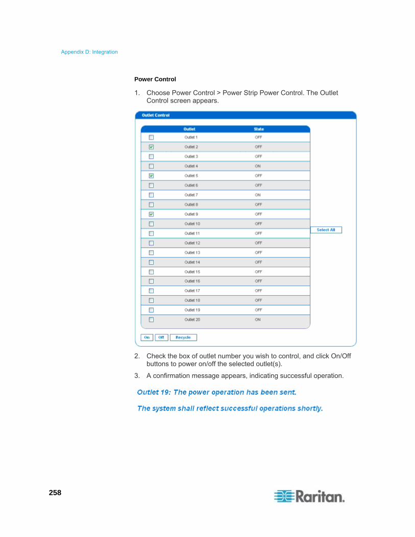
Appendix D: Integration
258
Power Control
1. Choose Power Control > Power Strip Power Control. The Outlet Control screen appears.
2. Check the box of outlet number you wish to control, and click On/Off buttons to power on/off the selected outlet(s).
3. A confirmation message appears, indicating successful operation.
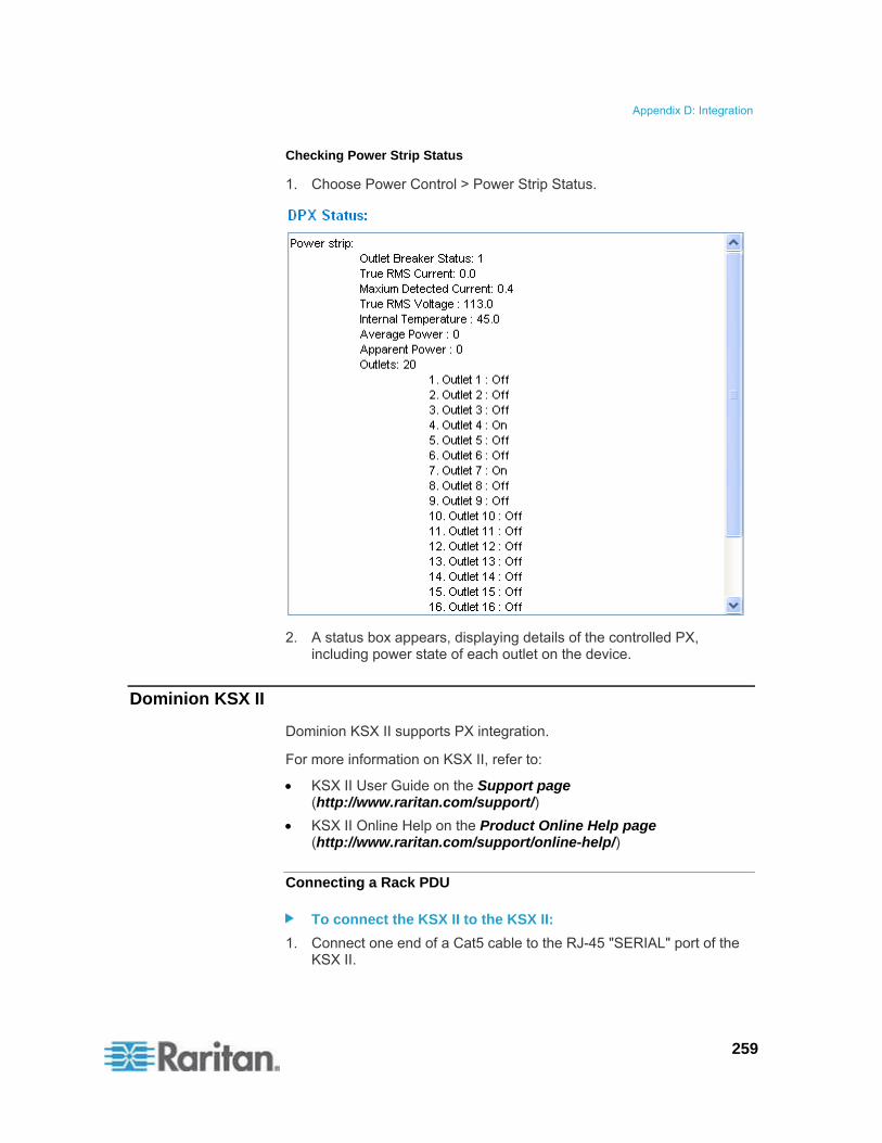
Appendix D: Integration
259
Checking Power Strip Status
1. Choose Power Control > Power Strip Status.
2. A status box appears, displaying details of the controlled PX, including power state of each outlet on the device.
Dominion KSX II
Dominion KSX II supports PX integration.
For more information on KSX II, refer to:
KSX II User Guide on the Support page (http://www.raritan.com/support/)
KSX II Online Help on the Product Online Help page (http://www.raritan.com/support/online-help/)
Connecting a Rack PDU
To connect the KSX II to the KSX II:
1. Connect one end of a Cat5 cable to the RJ-45 "SERIAL" port of the KSX II.
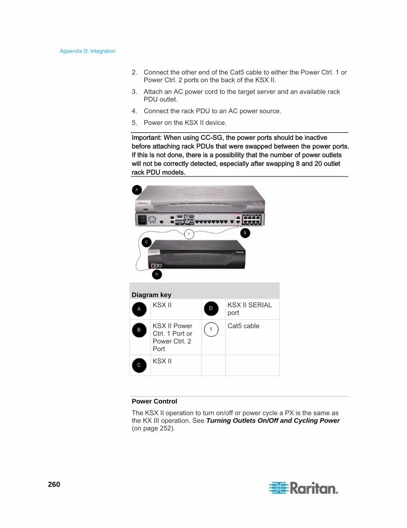
Appendix D: Integration
260
2. Connect the other end of the Cat5 cable to either the Power Ctrl. 1 or Power Ctrl. 2 ports on the back of the KSX II.
3. Attach an AC power cord to the target server and an available rack PDU outlet.
4. Connect the rack PDU to an AC power source.
5. Power on the KSX II device.
Important: When using CC-SG, the power ports should be inactive before attaching rack PDUs that were swapped between the power ports. If this is not done, there is a possibility that the number of power outlets will not be correctly detected, especially after swapping 8 and 20 outlet rack PDU models.
Diagram key
KSX II
KSX II SERIAL port
KSX II Power Ctrl. 1 Port or Power Ctrl. 2 Port
Cat5 cable
KSX II
Power Control
The KSX II operation to turn on/off or power cycle a PX is the same as the KX III operation. See Turning Outlets On/Off and Cycling Power (on page 252).

Appendix D: Integration
261
CommandCenter Secure Gateway
You can manage a PX from a CommandCenter Secure Gateway (CC-SG) if it is connected through any of the following Raritan products:
Dominion SX
Dominion KX
Paragon II
See the CC-SG Administrators Guide for more details.
Note: If you have to reboot or power OFF the PX device while it is integrated with a Raritan product under CC-SG management you should PAUSE MANAGEMENT of the integrated product until the PX device fully powers ON again. Failure to do so may result in the outlets being deleted from CC-SG's view and your power associations becoming lost when the PX device is back online.
Direct Control from CC-SG 4.0 or Later
CommandCenter Secure Gateway (CC-SG) 4.0 or later can discover PX units on the local network and can provide direct control over their outlet states (ON, OFF, and recycle).
You must upgrade your CC-SG to version 5.3 or later in order to manage or control the PX running in the FIPS mode. See FIPS Impact on Integration (on page 181).
Note: The models with the prefixes of DPXS, DPXR, DPCS, DPCR, and PX-nnnn (where n is a number) only support IPv4 networking protocol so CC-SG must use IPv4 to communicate with these models.
Power IQ Configuration
Sunbird's Power IQ is a software application that collects and manages the data from different PDUs installed in your server room or data center. With this software, you can:
Do bulk configuration for multiple PDUs
Name outlets on different PDUs
Switch on/off outlets on outlet-switching capable PDUs
If FIPS is enabled on your PX, Power IQ must use SNMP v3 to manage or control the PX running in the FIPS mode. See FIPS Impact on Integration (on page 181).

Appendix D: Integration
262
Suggestions for Power IQ SNMP Settings
When a PX is managed by Power IQ, it is strongly suggested to change the SNMP settings of Power IQ as shown below to minimize the number of "lost communications" errors reported by Power IQ. Usually Raritan support staff should have helped to properly configure these settings at the time of Power IQ installation if you purchase Power IQ from Raritan.
The following settings apply to all Power IQ releases.
PDUs managed by Power IQ over a LAN
SNMP timeout = 10 seconds
Number of retires = 3
PDUs managed by Power IQ over a mixture of networks - LAN and WAN
SNMP timeout = 15 or 30 seconds
Number of retires = 3
dcTrack
Sunbird's dcTrack® is a product that allows you to manage the data center. The PX is categorized as a power item in dcTrack. dcTrack offers an import wizard for conveniently adding the PX as well as other IT equipment to dcTrack for management.
You can use dcTrack to:
Record and manage the data center infrastructure and assets
Monitor the electrical consumption of the data center
Track environmental factors in the data center, such as temperature and humidity
Optimize the data center growth
For more information on dcTrack, refer to the online help accessible from the dcTrack application, or user documentation available on the Sunbird's website: http://support.sunbirddcim.com.

Appendix D: Integration
263
dcTrack Overview
dcTrack® is a powerful and intelligent data center management and automation application.
It has been designed by data center and IT professionals to provide broad and deep visibility into the data center. It empowers data center managers to plan for growth and change by optimizing their current operations, assets, and infrastructure.
With dcTrack, you can view everything in the data center from servers, blades, virtual servers and applications to data networks, IP addressing space and cabling. dcTrack also allows you to track real-time power consumption and manage raised floor space and rack elevations.
Use dcTrack to build your floor map data center map directly in the application, or import an existing floor map into the dcTrack. Further, dcTrack allows you to import AutoCAD® 2012 (and earlier) objects to build a data center map.
If you currently maintain data center information in spreadsheet format, that data can be imported into dcTrack using the Import wizard.
Isolate potential problems with end-to-end power and data circuits by visually tracing them. This allows you to identify all intermediate circuit points and locate problems.
By using dcTrack's workflow and change management feature, data center managers are better able to enforce best practices across the enterprise and meet ITIL framework guidelines. You can also opt to skip the Change Control workflow process and work in Request Bypass so requests are processed immediately.
dcTrack® can be used as a standalone product or integrated with Power IQ® for power and environmental monitoring.

264
The IPMI tool set is command-line that allows users to display channel information, print sensor data, and set LAN configuration parameters. The following explains the available IPMI commands.
Note: The open source IPMI tool can be downloaded from sourceforge, and compiled on Linux system .Then users can interact with the PX via IPMI protocol through this tool. An example at the Linux command shell is given as: $ ipmitool -I lan -H 192.168.51.58 -U admin -a channel info
In This Chapter
Channel Commands..............................................................................264 Event Commands ..................................................................................265 LAN Commands ....................................................................................266 Sensor Commands................................................................................268 OEM Commands ...................................................................................269 IPMI Privilege Levels .............................................................................280 IPMI in the FIPS Mode ..........................................................................281
Channel Commands
authcap <channel number> <max priv>
Displays information about the authentication capabilities of the selected channel at the specified privilege level. Possible privilege levels are:
1. Callback level
2. User level
3. Operator level
4. Administrator level
5. OEM Proprietary level
Example
$ ipmitool -I lan -H 192.168.51.58 -U admin -a channel authcap 14 5
See IPMI Privilege Levels (on page 280) for additional information about IPMI privileges.
Appendix E Using the IPMI Tool Set

Appendix E: Using the IPMI Tool Set
265
info [channel number]
Displays information about the selected channel. If no channel is given it displays information about the currently used channel:
Example
$ ipmitool -I lan -H 192.168.51.58 -U admin -a channel info
getaccess <channel number> [userid]
Configures the given userid as the default on the given channel number. When the given channel is subsequently used, the user is identified implicitly by the given userid.
Example
$ ipmitool -I lan -H allen-dpxpcr20-20 -U admin -P raritan1 channel getaccess 14 63
setaccess <channel number> <userid>[callin=on|off] [ipmi=on|off] [link=on|off] [privilege=level]
Configures user access information on the given channel for the given userid.
Example
$ ipmitool -I lan -H allen-dpxpcr20-20 -U admin -P raritan1 channel setaccess 14 63 privilege=5
getciphers <all | supported> <ipmi | sol> [channel]
Displays the list of cipher suites supported for the given application (ipmi or sol) on the given channel.
Example
$ ipmitool -I lan -H allen-dpxpcr20-20 -U admin -P raritan1 channel getciphers ipmi 14
Event Commands
The Event commands allow you to send pre-defined events to a Management Controller.

Appendix E: Using the IPMI Tool Set
266
<predefined event number>
Sends a pre-defined event to the System Event Log. The Currently supported values for are:
Temperature: Upper Critical: Going High
Voltage Threshold: Lower Critical: Going Low
Memory: Correctable ECC Error Detected
Note: These pre-defined events usually do not produce "accurate" SEL records for a particular system because they will not be correctly tied to a valid sensor number. However, they are sufficient to verify correct operation of the SEL.
Example
$ ipmitool -I lan -H allen-dpxpcr20-20 -U admin -P raritan1 event 1
file <filename>
Event log records specified in filename is added to the System Event Log. The format of each line in the file is as follows:
<{EvM Revision} {Sensor Type} {Sensor Num} {Event Dir/Type} {Event Data 0} {Event Data 1} {Event Data 2}>[# COMMENT]
Note: The Event Dir/Type field is encoded with the event direction as the high bit (bit 7) and the event type as the low 7 bits.
Example
0x4 0x2 0x60 0x1 0x52 0x0 0x0 # Voltage threshold: Lower Critical: Going Low
LAN Commands
The LAN commands allow you to configure the LAN channels.
print <channel>
Prints the current configuration for the given channel.

Appendix E: Using the IPMI Tool Set
267
set <channel> <parameter>
Sets the given parameter on the given channel. Valid parameters are:
ipaddr <x.x.x.x> Sets the IP address for this channel.
netmask <x.x.x.x> Sets the netmask for this channel.
macaddr <xx:xx:xx:xx:xx:xx> Sets the MAC address for this channel.
defgw ipaddr <x.x.x.x> Sets the default gateway IP address.
defgw macaddr <xx:xx:xx:xx:xx:xx> Sets the default gateway MAC address.
bakgw ipaddr <x.x.x.x> Sets the backup gateway IP address.
bakgw macaddr <xx:xx:xx:xx:xx:xx> Sets the backup gateway MAC address.
password <pass> Sets the null user password.
snmp <community string> Sets the SNMP community string.
user Enables user access mode for userid 1 (issue the `user' command to display information about userids for a given channel).
access <on|off> Set LAN channel access mode.
ipsrc Ses the IP address source:
none unspecified
static manually configured static IP address
dhcp address obtained by DHCP
bios address loaded by BIOS or system software
arp respond <on|off> Sets generated ARP responses.
arp generate <on|off> Sets generated gratuitous ARPs.
arp interval <seconds> Sets generated gratuitous ARP interval.
auth <level,...> <type,...> Sets the valid authtypes for a given auth level.
Levels: callback, user, operator, admin
Types: none, md2, md5, password, oem
cipher_privs <privlist> Correlates cipher suite numbers with the maximum privilege level that is allowed to use it. In this way, cipher suites can restricted to users with a given privilege level, so that, for example, administrators are required to use a stronger cipher suite than normal users.
The format of privlist is as follows. Each character represents a privilege level and the character position identifies the cipher suite number. For example, the first character represents cipher suite 1 (cipher suite 0 is reserved), the second represents cipher suite 2, and so on. privlist must be 15 characters in length.
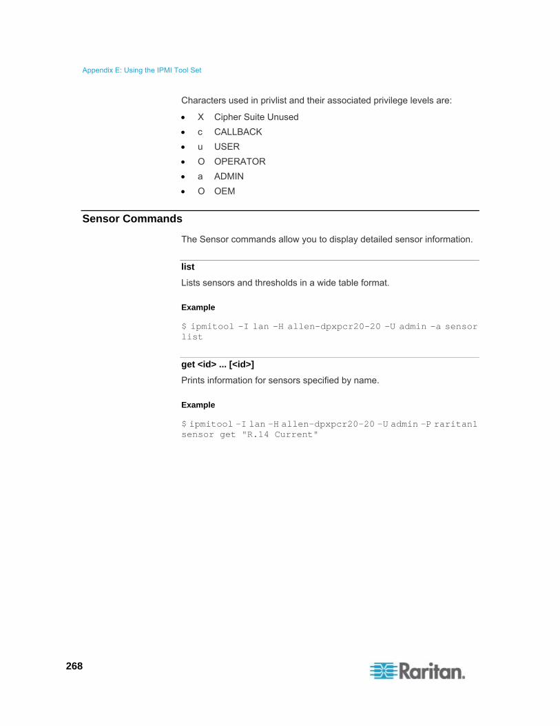
Appendix E: Using the IPMI Tool Set
268
Characters used in privlist and their associated privilege levels are:
X Cipher Suite Unused
c CALLBACK
u USER
O OPERATOR
a ADMIN
O OEM
Sensor Commands
The Sensor commands allow you to display detailed sensor information.
list
Lists sensors and thresholds in a wide table format.
Example
$ ipmitool -I lan -H allen-dpxpcr20-20 -U admin -a sensor list
get <id> ... [<id>]
Prints information for sensors specified by name.
Example
$ ipmitool -I lan -H allen-dpxpcr20-20 -U admin -P raritan1 sensor get "R.14 Current"

Appendix E: Using the IPMI Tool Set
269
thresh <id> <threshold> <setting>
This allows you to set a particular sensor threshold value. The sensor is specified by name. Valid thresholds are:
unr Upper Non-Recoverable
ucr Upper Critical
unc Upper Non-Critical
lnc Lower Non-Critical
lcr Lower Critical
lnr Lower Non-Recoverable
Example
$ ipmitool -I lan -H allen-dpxpcr20-20 -U admin -P raritan1 sensor thresh "R.14 Current" unr 10.5
OEM Commands
You can use the OEM commands to manage and control the operation of the PX device.
OEM Net-Fn is as defined below:
#define IPMI_NETFN_OEM_PP 0x3C
An OEM command's syntax:
#ipmitool -H <IP address> -U <User> -P <Password> raw 0x3c <ID> <Request data>
<IP address>: IP address of the PX
<User>: User name to log in to the PX
<Password>: Password for the specified user name
<ID>: The ID that represents the OEM command you want to perform on the PX
<Request data>: <Request data> can be one single parameter or a combination of parameters. For example, to turn on a receptacle, it requires two parameters: the first is the number representing the target receptacle, and the second is the value representing the new receptacle state you want.
ID numbers of OEM commands:
The table lists each OEM command and gives its ID. The sections that follow explain each command in greater detail.

Appendix E: Using the IPMI Tool Set
270
Command Name Id
Set Power On Delay Command 0x10
Get Power On Delay Command 0x11
Set Receptacle State Command 0x12
Get Receptacle State Command 0x13
Set Group State Command 0x14
Set Group Membership Command 0x15
Get Group Membership Command 0x16
Set Group Power On Delay Command 0x17
Get Group Power On Delay Command 0x18
Set Receptacle ACL 0x19
Get Receptacle ACL 0x1A
Set Sensor Calibration 0x1B
Test Actors 0x1C
Test Sensors 0x1D
Set Power Cycle Delay Command 0x1E
Get Power Cycle Delay Command 0x1F
A Note about Group Commands
When sending Group commands, a valid group number (0 through 23, or 255) must be used. Only the group number itself can be sent, alpha-numeric expressions for group numbers are incorrect, and cause the command to be ignored.
For example, sending the following is incorrect:
#ipmitool -H 192.168.80.43 -U admin -P pass raw 0x3c 0x14 grp2 0
The PX ignores this command.

Appendix E: Using the IPMI Tool Set
271
A Note about Outlet Numbers
An outlet command uses decimal numerals to represent outlets. Each decimal numeral must be converted into a binary one consisting of 8 numeric digits for indicating 8 outlets. Note that the lowest-numbered outlet is located on the rightmost digit of 8 digits.
The first decimal numeral represents outlets 1 to 8, and its outlet sequence in a binary numeral is shown below:
8 - 7 - 6 - 5 - 4 - 3 - 2 - 1
For example:
0000 0001 refers to outlet 1.
0000 0101 refers to outlets 1 and 3.
The second decimal numeral represents outlets 9 to 16, and its outlet sequence in a binary numeral is shown below:
16 - 15 - 14 - 13 - 12 - 11 - 10 - 9
For example:
0000 1001 refers to outlets 9 and 12.
0000 1100 refers to outlets 11 and 12.
The third decimal numeral represents outlets 17 to 24, and its outlet sequence in a binary numeral is shown below:
24 - 23 - 22 - 21 - 20 - 19 - 18 - 17
For example:
0001 0101 refers to outlets 17, 19, and 21.
0001 0111 refers to outlets 17, 18, 19 and 21.
Below is the outlet conversion table illustrating the conversion from decimal to binary numerals:
Decimal Binary Decimal Binary
1 0000 0001 13 0000 1101
2 0000 0010 14 0000 1110
3 0000 0011 15 0000 1111
4 0000 0100 16 0001 0000
5 0000 0101 17 0001 0001
6 0000 0110 18 0001 0010
7 0000 0111 19 0001 0011
8 0000 1000 20 0001 0100
9 0000 1001 21 0001 0101
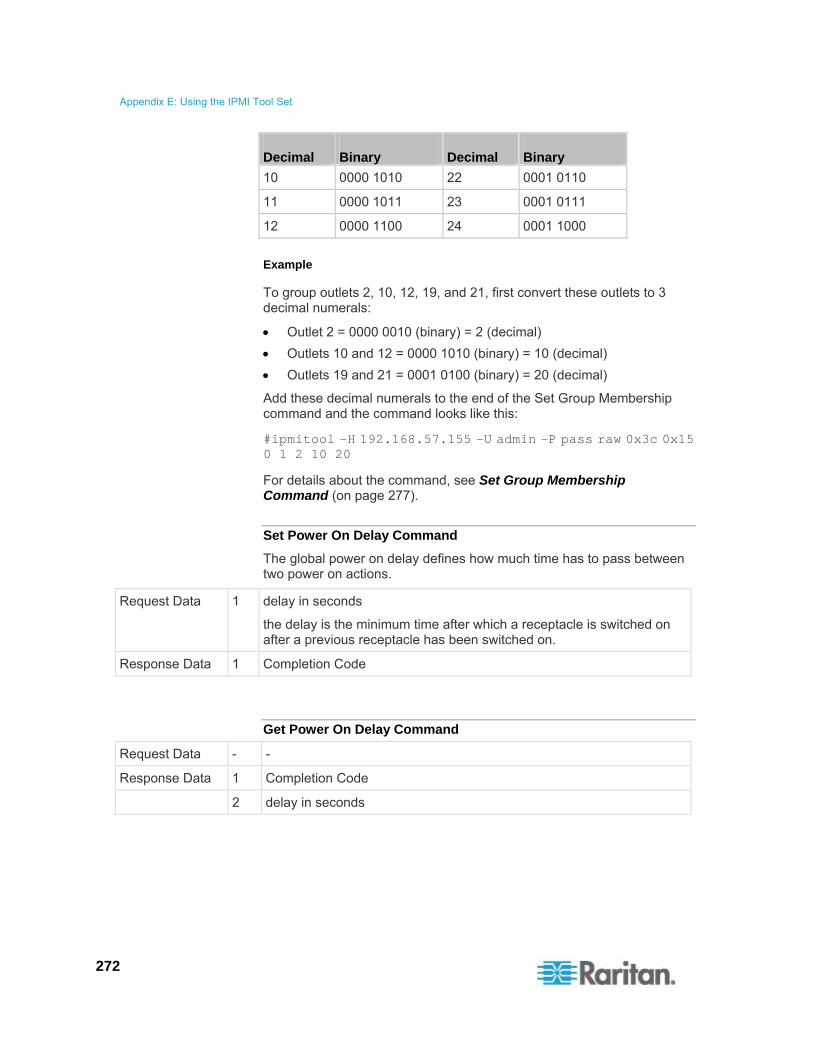
Appendix E: Using the IPMI Tool Set
272
Decimal Binary Decimal Binary
10 0000 1010 22 0001 0110
11 0000 1011 23 0001 0111
12 0000 1100 24 0001 1000
Example
To group outlets 2, 10, 12, 19, and 21, first convert these outlets to 3 decimal numerals:
Outlet 2 = 0000 0010 (binary) = 2 (decimal)
Outlets 10 and 12 = 0000 1010 (binary) = 10 (decimal)
Outlets 19 and 21 = 0001 0100 (binary) = 20 (decimal)
Add these decimal numerals to the end of the Set Group Membership command and the command looks like this:
#ipmitool -H 192.168.57.155 -U admin -P pass raw 0x3c 0x15 0 1 2 10 20
For details about the command, see Set Group Membership Command (on page 277).
Set Power On Delay Command
The global power on delay defines how much time has to pass between two power on actions.
Request Data 1 delay in seconds
the delay is the minimum time after which a receptacle is switched on after a previous receptacle has been switched on.
Response Data 1 Completion Code
Get Power On Delay Command
Request Data - -
Response Data 1 Completion Code
2 delay in seconds

Appendix E: Using the IPMI Tool Set
273
Set Receptacle State Command
The following command is used to switch on/off and recycle individual receptacles. See OEM Commands (on page 269) for detailed information on the OEM command syntax.
#ipmitool -H <IP address> -U <User name> -P <Password> raw 0x3c 0x12 <Request data>
<Request data> includes two pieces of information:
Receptacle number which is zero-based, that is, 0 for outlet 1, 1 for outlet 2, 2 for outlet 3, and so on.
The value for setting the receptacle state.
Request Data 1 # of receptacle, 0 based, highest valid # depends on device model
2 new receptacle state:
0 = power off
1 = power on
2 = recycle
Response Data 1 Completion Code
The following illustrates several outlet switching commands. Note that outlet 1 is represented by the number zero (0) prior to the final digit in the IPMI command.
To turn off Outlet 1:
#ipmitool -H <IP address> -U <User name> -P <Password> raw 0x3c 0x12 0 0
To turn on Outlet 1:
#ipmitool -H <IP address> -U <User name> -P <Password> raw 0x3c 0x12 0 1
To power cycle Outlet 1:
#ipmitool -H <IP address> -U <User name> -P <Password> raw 0x3c 0x12 0 2
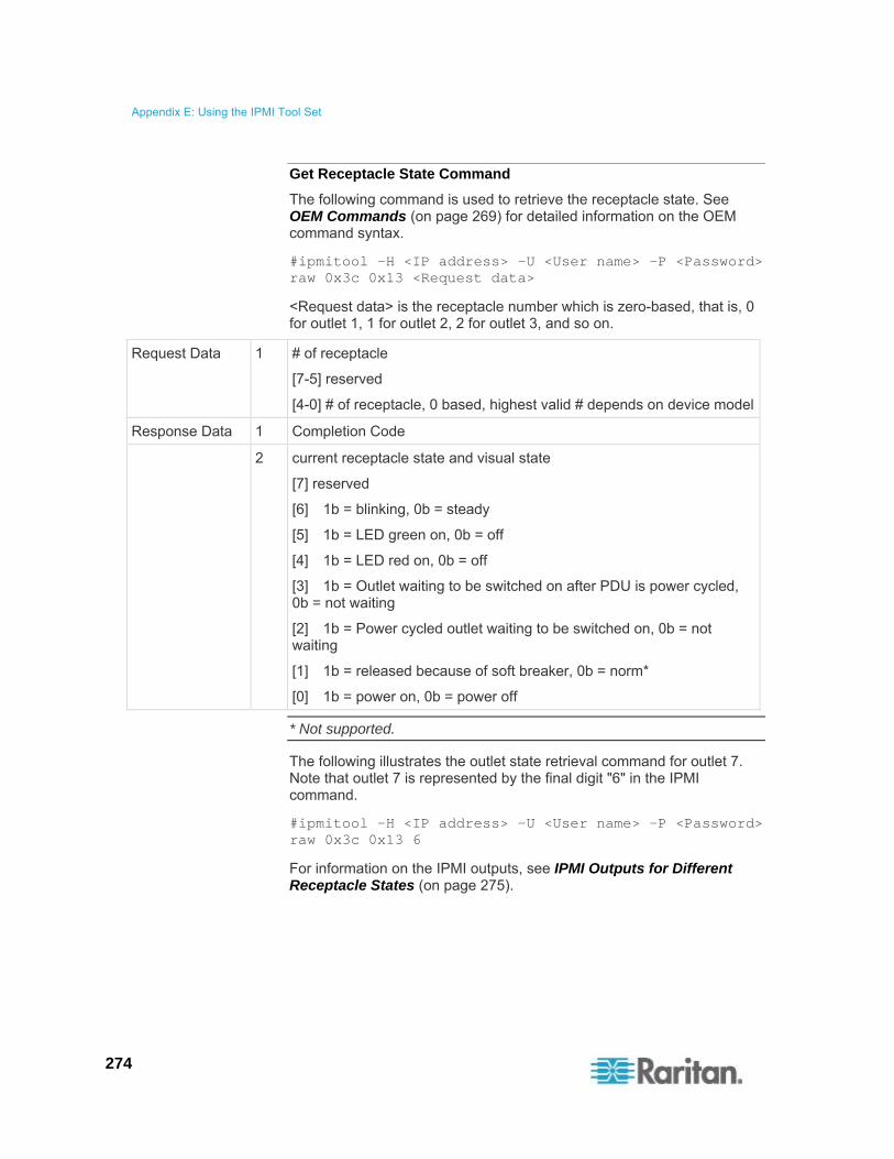
Appendix E: Using the IPMI Tool Set
274
Get Receptacle State Command
The following command is used to retrieve the receptacle state. See OEM Commands (on page 269) for detailed information on the OEM command syntax.
#ipmitool -H <IP address> -U <User name> -P <Password> raw 0x3c 0x13 <Request data>
<Request data> is the receptacle number which is zero-based, that is, 0 for outlet 1, 1 for outlet 2, 2 for outlet 3, and so on.
Request Data 1 # of receptacle
[7-5] reserved
[4-0] # of receptacle, 0 based, highest valid # depends on device model
Response Data 1 Completion Code
2 current receptacle state and visual state
[7] reserved
[6] 1b = blinking, 0b = steady
[5] 1b = LED green on, 0b = off
[4] 1b = LED red on, 0b = off
[3] 1b = Outlet waiting to be switched on after PDU is power cycled, 0b = not waiting
[2] 1b = Power cycled outlet waiting to be switched on, 0b = not waiting
[1] 1b = released because of soft breaker, 0b = norm*
[0] 1b = power on, 0b = power off
* Not supported.
The following illustrates the outlet state retrieval command for outlet 7. Note that outlet 7 is represented by the final digit "6" in the IPMI command.
#ipmitool -H <IP address> -U <User name> -P <Password> raw 0x3c 0x13 6
For information on the IPMI outputs, see IPMI Outputs for Different Receptacle States (on page 275).

Appendix E: Using the IPMI Tool Set
275
IPMI Outputs for Different Receptacle States
After issuing the "Get Receptacle State" IPMI command, you shall receive one of the following IPMI outputs, which include both outlet states and outlet LED states. For information on outlet LED states, see Outlets (on page 46).
When this outlet is turned OFF:
IPMI output 20
Explanation 20 is the equivalent of the binary numerals 0010 0000, which indicates the outlet is turned off and its outlet LED is green.
Binary bit 0 off (0) = Outlet Off
Binary bit 5 on (1) = Outlet LED Green On
When this outlet is turned ON:
IPMI output 11
Explanation 11 is the equivalent of the binary numerals 0001 0001, which indicates the outlet is turned on and its outlet LED is red.
Binary bit 0 on (1) = Outlet On
Binary bit 4 on (1) = Outlet LED Red On
When this outlet's current value is above the upper non-critical or critical threshold:
IPMI output 51
Explanation 51 is the equivalent of the binary numerals 0101 0001, which indicates the outlet is turned on and its outlet LED is flashing red.
Binary bit 0 on (1) = Outlet On
Binary bit 4 on (1) = Outlet LED Red On
Binary bit 6 on (1) = Outlet LED Blinking
When power cycling the outlet in question:
IPMI output 24
Explanation 24 is the equivalent of the binary numerals 0010 0100, which indicates the outlet is waiting to be turned on after power cycling the outlet.
Binary bit 2 on ( 1) = Power-cycled outlet waiting to be switched on
Binary bit 5 on (1) = Outlet LED Green On
When power cycling the PDU:

Appendix E: Using the IPMI Tool Set
276
IPMI output 28
Explanation 28 is the equivalent of the binary numerals 0010 1000, which indicates the outlet is waiting to be turned on after power cycling the PDU.
Binary bit 3 on ( 1) = Outlet waiting to be switched on after PDU is power cycled
Binary bit 5 on (1) = Outlet LED Green On
Get Receptacle State and Data Command
Request Data 1 # of receptacle
[7 - 5] reserved
[4 - 0] # of receptacle, 0 based, highest valid # depends on device model
Response Data 1 Completion Code
2 current receptacle state and visual state
[7] reserved
[6] 1b = blinking, 0b = steady
[5] 1b = LED green on, 0b = off
[4] 1b = LED red on, 0b = off
[3] 1b = enqueued to be switched on, 0b = not enqueued
[2] 1b = in power cycle delay phase, 0b = not delayed
[1] 1b = released because of soft breaker, 0b = norm
[0] 1b = power on, 0b = power off
3 Number of bytes of data = 2 or 6
4 Apparent Power
5 Active Power
6-9 Active Energy, LSB First
Set Group State Command
This command is used to switch on/off all receptacles belonging to a group. There is no Get Group State Command. Getting the state of a receptacle has to be carried out with Get Receptacle State Command.
Request Data 1 # of group

Appendix E: Using the IPMI Tool Set
277
[7 - 5] reserved
[4 - 0] group #, valid numbers: 0 - 23, 255
2 new state
[7 - 1] reserved
[0] 1b = power on, 0b = power off
Response Data 1 Completion Code
Set Group Membership Command
Request Data 1 # of group
[7 - 5] reserved
[4 - 0] group #, valid numbers: 0 - 23, 255
2 [7 - 1] reserved
[0] 1b = enable group, 0b = disable group
3 [7] 1b = receptacle 7 belongs to group
...
[0] 1b = receptacle 0 belongs to group
4 [7] 1b = receptacle 15 belongs to group
...
[0] 1b = receptacle 8 belongs to group
5 [7] 1b = receptacle 23 belongs to group
...
[0] 1b = receptacle 16 belongs to group
Response Data 1 Completion Code
Get Group Membership Command
Request Data 1 # of group
[7 - 5] reserved
[4 - 0] group #, valid numbers: 0 - 23, 255
Response Data 1 Completion Code
2 [7 - 1] reserved
[0] 1b = group is enabled, 0b = group is disabled
3 [7] 1b = receptacle 7 belongs to group

Appendix E: Using the IPMI Tool Set
278
...
[0] 1b = receptacle 0 belongs to group
4 [7] 1b = receptacle 15 belongs to group
...
[0] 1b = receptacle 8 belongs to group
5 [7] 1b = receptacle 23 belongs to group
...
[0] 1b = receptacle 16 belongs to group
Set Group Power On Delay Command
Request Data 1 # of group
[7 - 5] reserved
[4 - 0] group #, valid numbers: 0 - 23, 255
2 delay in seconds
This delay overwrites the global delay for all receptacles in that group. The delay applies not only when using the Set Group State Command but also when using Set Receptacle State Command.
Response Data 1 Completion Code
Get Group Power On Delay Command
Request Data 1 # of group
[7 - 5] reserved
[4 - 0] group #, valid numbers: 0 - 23, 255
Response Data 1 Completion Code
2 delay in seconds
Set Receptacle ACL
ACLs define who is authorized to change the state of a receptacle. ACLs are stored for each individual outlet. A single ACL entry defines whether a certain user id or privilege level is allowed or denied to issue control commands for the outlet. ACL are evaluated top to bottom, hence order of ACL entries is important. If there is no ACL entry at all, receptacle ACLs are disabled, i.e. any user id has access.

Appendix E: Using the IPMI Tool Set
279
Request Data 1 # of receptacle
2 number of ACL entries to follow
3
+N
ACL entry
[7] 0b = deny, 1b = allow
[6] 0b = user id, 1b = privilege level
[5 - 0] user id or privilege level depending on [6]
Response Data 1 Completion Code
Get Receptacle ACL
Request Data 1 # of receptacle
Response Data 1 Completion Code
2 number of ACL entries to follow
3
+N
ACL entry
[7] 0b = deny, 1b = allow
[6] 0b = user id, 1b = privilege level
[5 - 0] user id or privilege level depending on [6]
Test Actors
Used for hardware testing during production
Request Data 1 [7 - 2] reserved
[1] Beeper test, 0b - disable, 1b - enable
[0] 7 segment display test, 0b - disable, 1b - enable
Response Data 1 Completion Code
Test Sensors
Used for hardware testing during production
Request Data 1 -
Response Data 1 Completion Code
2 [7 - 2] reserved
[1] down button, 0b - not pressed, 1b - pressed
[0] up button, 0b - not pressed, 1b - pressed

Appendix E: Using the IPMI Tool Set
280
Set Power Cycle Delay Command
Request Data 1 # of receptacle (0xFF for global unit delay)
2 Delay (seconds), 1-255 for unit and receptacle, 0 fallback to unit delay (receptacle only)
Response Data 1 Completion Code
Get Power Cycle Delay Command
Request Data 1 # of receptacle (0xFF for global unit delay)
Response Data 1 Completion Code
2 Delay (seconds), 1-255, 0 if not set (receptacle only)
Note: Values greater than 255 cannot be sent to the PX via IPMI. To set the Power Cycle Delay to longer than 255 seconds, use the web interface.
IPMI Privilege Levels
The IPMI privilege level that you select determines:
IPMI Privilege Level:
No Access
Callback User Operator Administrator OEM
Authentication Settings
No Yes/No Yes/No Yes/No Yes/No Yes/No
Change Password
No No No No Yes Yes
Date/Time Settings
No No No Yes Yes Yes
Firmware Update
No Yes/No Yes/No Yes/No Yes/No Yes/No
Log Settings No Yes/No Yes/No Yes/No Yes/No Yes/No
Log View No Yes/No Yes/No Yes/No Yes/No Yes/No
Network Dyn/DSN
No No No No Yes Yes

Appendix E: Using the IPMI Tool Set
281
IPMI Privilege Level:
No Access
Callback User Operator Administrator OEM
Settings
Power Control Setting
No Yes/No Yes/No Yes/No Yes/No Yes/No
SNMP Setting No Yes/No Yes/No Yes/No Yes/No Yes/No
SSH/Telnet Access
No Yes/No Yes/No Yes/No Yes/No Yes/No
SSL Certificate Management
No Yes/No Yes/No Yes/No Yes/No Yes/No
Security Settings
No Yes/No Yes/No Yes/No Yes/No Yes/No
Unit Reset No Yes/No Yes/No Yes/No Yes/No Yes/No
User/Group Management
No No No No Yes Yes
User Group Permissions
No Yes/No Yes/No Yes/No Yes/No Yes/No
IPMI in the FIPS Mode
In the FIPS mode, you must meet the requirements below to use the IPMI.
Only IPMI v2.0 is supported.
FIPS approved algorithms for IPMI:
Authentication algorithms:
RAKP-HMAC-SHA1
RAKP-HMAC-SHA256
Integrity algorithms:
HMAC-SHA1-96
HMAC-SHA256-128
Encryption algorithms:
AES-CBC-128
ipmitool commands:
You must use the lanplus interface.
Example:

Appendix E: Using the IPMI Tool Set
282
$ ipmitool -I lanplus -H allen-dpxpcr20-20 -U admin -P raritan1 sensor get "R.14 Current"
The parameter used with the -C option for ciphersuite must be 3. This is because the -C 3 option corresponds to RAKP-HMAC-SHA1 authentication, HMAC-SHA1-96 integrity and AES-CBC-128 encryption algorithms.
Example:
$ ipmitool -I lanplus -U admin -P raritan1 -C 3 -H 192.168.50.13 mc info
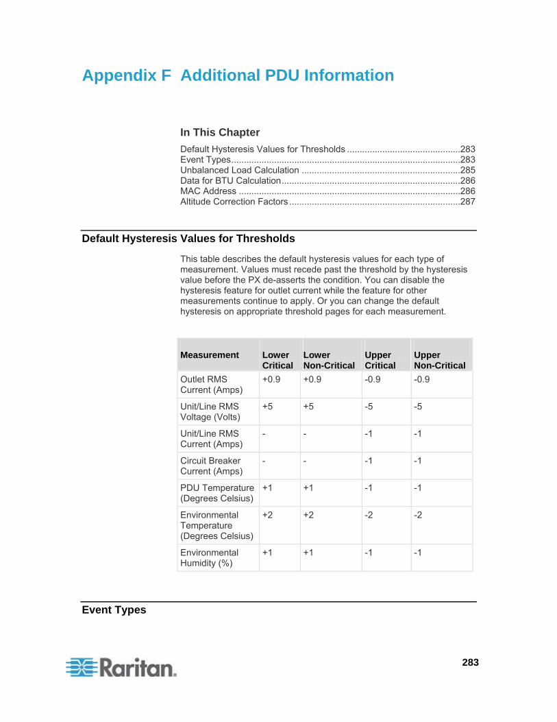
283
In This Chapter
Default Hysteresis Values for Thresholds .............................................283 Event Types...........................................................................................283 Unbalanced Load Calculation ...............................................................285 Data for BTU Calculation.......................................................................286 MAC Address ........................................................................................286 Altitude Correction Factors ....................................................................287
Default Hysteresis Values for Thresholds
This table describes the default hysteresis values for each type of measurement. Values must recede past the threshold by the hysteresis value before the PX de-asserts the condition. You can disable the hysteresis feature for outlet current while the feature for other measurements continue to apply. Or you can change the default hysteresis on appropriate threshold pages for each measurement.
Measurement Lower Critical
Lower Non-Critical
Upper Critical
Upper Non-Critical
Outlet RMS Current (Amps)
+0.9 +0.9 -0.9 -0.9
Unit/Line RMS Voltage (Volts)
+5 +5 -5 -5
Unit/Line RMS Current (Amps)
- - -1 -1
Circuit Breaker Current (Amps)
- - -1 -1
PDU Temperature (Degrees Celsius)
+1 +1 -1 -1
Environmental Temperature (Degrees Celsius)
+2 +2 -2 -2
Environmental Humidity (%)
+1 +1 -1 -1
Event Types
Appendix F Additional PDU Information

Appendix F: Additional PDU Information
284
Event Type Examples
Outlet Control Outlet(#) switched on by user
Outlet(#) switched off by user
Outlet(#) cycled by user
Outlet/Unit/Environmental Sensors
Assertion: Environmental Temperature (#) above upper non-critical threshold
Deassertion: Environmental Temperature (#) above upper critical threshold
User/Group Administration User added successfully
User successfully changed
User successfully deleted
User password successfully changed
Group added successfully
Group successfully changed
Group successfully deleted
Security Relevant User login failed
User Activity User logged in successfully
User logged out
User session timeout
Note: The user activity entries in the event log always show the IP address of the computer that logged in or out. Entries with an IP address of 127.0.0.1 (the loopback IP address) represent a serial connection and a CLP session.
Device Operation Device successfully started
Device Management The Device update has started
Virtual Device Management Master PDU lost connectivity with SlaveIPAddress

Appendix F: Additional PDU Information
285
Unbalanced Load Calculation
Unbalanced current information is available on 3-phase models only. This section explains how the PX calculates the unbalanced current percentage.
Calculation:
1. Calculate the average current of all 3 lines.
Average current = (L1+L2+L3) / 3
2. Calculate each line's current unbalance by having each line current subtracted and divided with the average current.
L1 current unbalance = (L1 - average current) / average current
L2 current unbalance = (L2 - average current) / average current
L3 current unbalance = (L3 - average current) / average current
3. Determine the maximum absolute value among three lines' current unbalance values.
Maximum (|L1 current unbalance|, |L2 current unbalance|, |L3 current unbalance|)
4. Convert the maximum value to a percentage.
Unbalanced load percent = 100 * maximum current unbalance
Example:
Each line's current:
L1 = 5.5 amps
L2 = 5.2 amps
L3 = 4.0 amps

Appendix F: Additional PDU Information
286
Average current: (5.5+5.2+4.0) / 3 = 4.9 amps
L1 current unbalance: (5.5 - 4.9) / 4.9 = 0.1224
L2 current unbalance: (5.2 - 4.9) / 4.9 = 0.0612
L3 current unbalance: (4.0 - 4.9) / 4.9 = -0.1837
Maximum current unbalance:
Maximum (|0.1224|, |0.0612|, |-0.1837|) = 0.1837
Current unbalance converted to a percentage:
100 * (0.1837) = 18%
Data for BTU Calculation
If you need to calculate the heat (BTU/hr) generated by the PX device, use the following power data in the BTU calculation formula.
Model name Maximum power (Watt)
PX-nnnn, DPXS, DPXR, DPCS and DPCR series
24
The letter "n" in the above PX-nnnn model name represents a number.
MAC Address
A label is affixed to the PX, showing both the serial number and MAC address.
You can find the IP address of the PX through the MAC address by using commonly-used network tools. Contact your LAN administrator for assistance.

Appendix F: Additional PDU Information
287
Altitude Correction Factors
If a Raritan differential air pressure sensor is attached to your device, the altitude you enter for the device can serve as an altitude correction factor. That is, the reading of the differential air pressure sensor will be multiplied by the correction factor to get a correct reading.
This table shows the relationship between different altitudes and correction factors.
Altitude (meters) Altitude (feet) Correction factor
0 0 0.95
250 820 0.98
425 1394 1.00
500 1640 1.01
740 2428 1.04
1500 4921 1.15
2250 7382 1.26
3000 9842 1.38

288
This section provides an LDAP example for illustrating the configuration procedure using Microsoft Active Directory® (AD). To configure LDAP authentication, four main steps are required:
a. Determine user accounts and groups intended for the PX
b. Create user groups for the PX on the AD server
c. Configure LDAP authentication on the PX device
d. Configure user groups on the PX device
In This Chapter
Step A. Determine User Accounts and Groups .................................... 288 Step B. Configure User Groups on the AD Server ............................... 289 Step C. Configure LDAP Authentication on the PX Device .................. 290 Step D. Configure User Groups on the PX Device ............................... 293
Step A. Determine User Accounts and Groups
Determine the user accounts and groups that are authenticated for accessing the PX. In this example, we will create two user groups with different permissions. Each group will consist of two user accounts available on the AD server.
User groups User accounts (members)
usera PX_User
pxuser2
userb PX_Admin
pxuser
Group permissions:
The PX_User group will have neither system permissions nor outlet permissions.
The PX_Admin group will have full system and outlet permissions.
Appendix G LDAP Configuration Illustration

Appendix G: LDAP Configuration Illustration
289
Step B. Configure User Groups on the AD Server
You must create the groups for the PX on the AD server, and then make appropriate users members of these groups.
In this illustration, we assume:
The groups for the PX are named PX_Admin and PX_User.
User accounts pxuser, pxuser2, usera and userb already exist on the AD server.
To configure the user groups on the AD server:
1. On the AD server, create new groups -- PX_Admin and PX_User.
Note: See the documentation or online help accompanying Microsoft AD for detailed instructions.
2. Add the pxuser2 and usera accounts to the PX_User group.
3. Add the pxuser and userb accounts to the PX_Admin group.
4. Verify whether each group comprises correct users.

Appendix G: LDAP Configuration Illustration
290
Step C. Configure LDAP Authentication on the PX Device
You must enable and set up LDAP authentication properly on the PX device to use external authentication.
In the illustration, we assume:
The DNS server settings have been configured properly. See Modifying the Network Settings (on page 73) and Role of a DNS Server (on page 74).
The AD server's domain name is techadssl.com, and its IP address is 192.168.56.3.
The AD protocol is NOT encrypted over SSL/TLS.
The AD server uses the default TCP port 389.
Anonymous bind is used.
There is no backup AD server.
The FIPS mode is disabled.
To configure LDAP authentication:
1. Choose Device Settings > Authentication. The Authentication Settings page opens.
2. Select the LDAP radio button to enable the LDAP section of the page.
3. Provide the PX with the information about the AD server.
Type of external LDAP server - Select "Microsoft Active Directory" from the drop-down list.
User LDAP Server - Type the domain name techadssl.com or IP address 192.168.56.3.
Important: Without the SSL encryption enabled, you can type either the domain name or IP address in this field, but you must type the fully qualified domain name if the SSL encryption is enabled.
Backup User LDAP Server - Leave the field empty because a backup AD server is unavailable.
SSL Enabled - Have the checkbox deselected since the SSL encryption is not applied in this example.
Port - Ensure the field is set to 389.
SSL Port and Certificate File - Skip the two fields since the SSL encryption is not enabled.
Bind with credentials - Make sure this checkbox is deselected since anonymous bind is used.

Appendix G: LDAP Configuration Illustration
291
Bind DN and Password - Skip these two fields because anonymous bind is used.
Base DN of user LDAP server - Type dc=techadssl,dc=com as the starting point where your search begins on the AD server.
Name of login-name attribute - Type sAMAccountName because the LDAP server is Microsoft Active Directory.
Name of user-entry objectclass - The field is optional. The object class information is helpful for filtering out additional objects in a large directory structure. In this example, we leave it blank.
User Search Subfilter - The field is optional. The subfilter information is also useful for filtering out additional objects in a large directory structure. In this example, we leave it blank.

Appendix G: LDAP Configuration Illustration
292
Active Directory Domain - Type techadssl.com.
Note: For more information on LDAP configuration, see Setting Up LDAP Authentication (on page 135).
4. Click Apply. The LDAP authentication is activated.
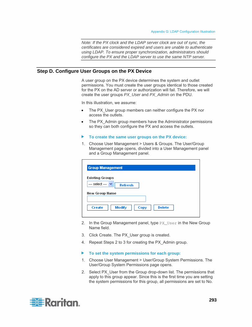
Appendix G: LDAP Configuration Illustration
293
Note: If the PX clock and the LDAP server clock are out of sync, the certificates are considered expired and users are unable to authenticate using LDAP. To ensure proper synchronization, administrators should configure the PX and the LDAP server to use the same NTP server.
Step D. Configure User Groups on the PX Device
A user group on the PX device determines the system and outlet permissions. You must create the user groups identical to those created for the PX on the AD server or authorization will fail. Therefore, we will create the user groups PX_User and PX_Admin on the PDU.
In this illustration, we assume:
The PX_User group members can neither configure the PX nor access the outlets.
The PX_Admin group members have the Administrator permissions so they can both configure the PX and access the outlets.
To create the same user groups on the PX device:
1. Choose User Management > Users & Groups. The User/Group Management page opens, divided into a User Management panel and a Group Management panel.
2. In the Group Management panel, type PX_User in the New Group Name field.
3. Click Create. The PX_User group is created.
4. Repeat Steps 2 to 3 for creating the PX_Admin group.
To set the system permissions for each group:
1. Choose User Management > User/Group System Permissions. The User/Group System Permissions page opens.
2. Select PX_User from the Group drop-down list. The permissions that apply to this group appear. Since this is the first time you are setting the system permissions for this group, all permissions are set to No.
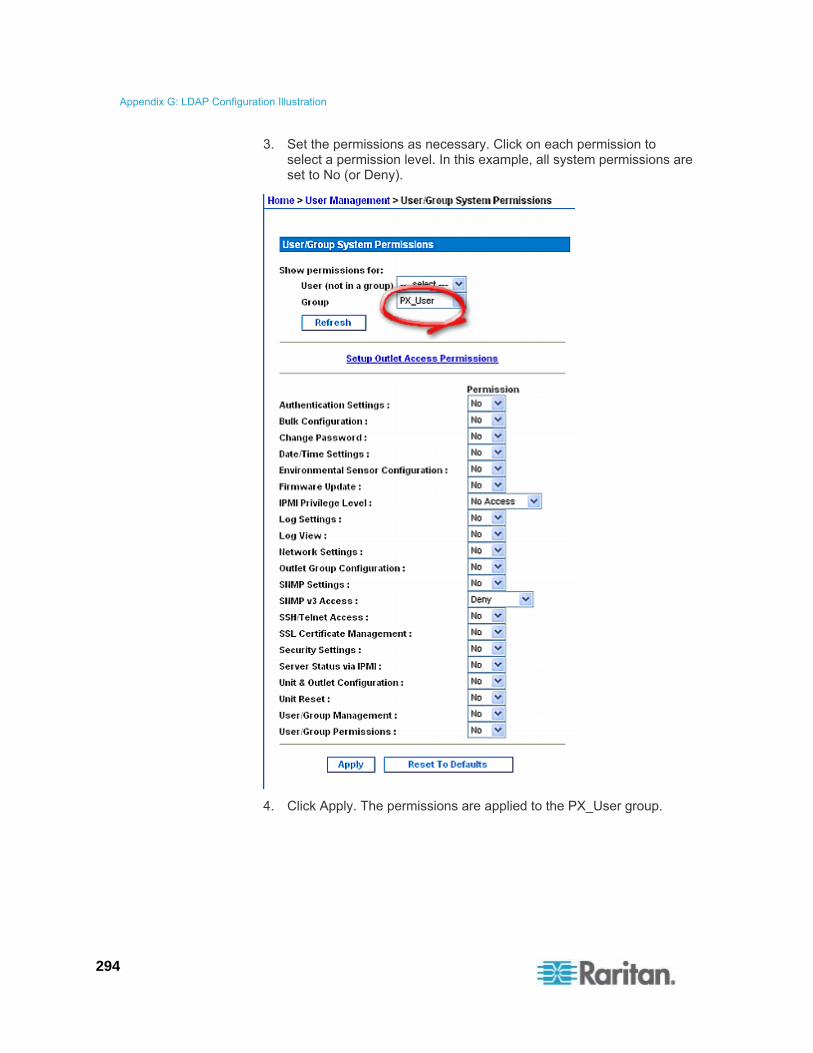
Appendix G: LDAP Configuration Illustration
294
3. Set the permissions as necessary. Click on each permission to select a permission level. In this example, all system permissions are set to No (or Deny).
4. Click Apply. The permissions are applied to the PX_User group.

Appendix G: LDAP Configuration Illustration
295
5. Repeat Steps 2 to 4 to set the permissions for the PX_Admin group. In this example, all system permissions are set to Yes (or Read-Write).
To set the outlet permissions for each group:
1. Choose User Management > User/Group Outlet Permissions. The User/Group Outlet Permissions page opens.
2. Select PX_User from the Group drop-down list. The permissions that apply to this group appear. Since this is the first time you are setting the outlet permissions for this group, all permissions are set to No.

Appendix G: LDAP Configuration Illustration
296
3. Select an appropriate permission level for each outlet. In this example, all outlet permissions are set to No.
4. Click Apply. The permissions are applied to the PX_User group.

Appendix G: LDAP Configuration Illustration
297
5. Repeat Steps 2 to 4 to set the permissions for the PX_Admin group. In this example, all outlet permissions are set to Yes.
298
You can reset the PX settings, including the administrator password, at the local serial console.
To establish a serial connection, see Connecting the PX to a Computer (on page 33).
In This Chapter
Resetting to Factory Defaults ................................................................298 Resetting the Administrator Password ..................................................299
Resetting to Factory Defaults
For security reasons, the PX device can be reset to factory defaults only at the local console.
Important: Exercise caution before resetting the PX to its factory defaults. This erases existing information and customized settings, such as user profiles, threshold values, and so on.
You must have the "Unit & Outlet Configuration" and "Unit Reset" permissions to perform a reset.
When resetting to factory defaults, do not use a DB9-to-USB adapter to connect the PX serial cable to your PC. This may result in misinterpreted characters at the special prompt. Connect the PX serial cable to a PC with a DB9 serial port instead.
To reset to factory defaults:
1. Connect a computer to the PX device. See Connecting the PX to a Computer (on page 33).
2. Launch a terminal emulation program such as HyperTerminal, Kermit, or PuTTY, and open a window on the PX. Make sure the serial port settings use this configuration:
Bits per second = 9600
Data bits = 8
Stop bits = 1
Parity = None
Flow control = None
3. If the window is blank, press Enter. The Welcome message appears.
4. Type clp at the command prompt and press Enter.
Appendix H Resetting the PDU Settings

Appendix H: Resetting the PDU Settings
299
5. Type your user name and password to log in to the CLP interface when prompted. See With HyperTerminal (on page 207).
6. Type the following command and press Enter.
clp:/-> set /system1 FactoryDefaults=true
7. Wait until the Welcome message appears, indicating that the reset is completed.
Note: HyperTerminal is available on Windows operating systems prior to Windows Vista. For Windows Vista or later versions, you may use PuTTY, which is a free program you can download from the Internet. See PuTTY's documentation for details on configuration.
Resetting the Administrator Password
If you lose the password for the "admin" user, you can reset the password at the local serial console.
To reset the administrator password:
1. Connect a computer to the PX device. See Connecting the PX to a Computer (on page 33).
2. Launch a terminal emulation program such as HyperTerminal, Kermit, or PuTTY, and open a window on the PX. Make sure the serial port settings use this configuration:
Bits per second = 9600
Data bits = 8
Stop bits = 1
Parity = None
Flow control = None
3. If the window is blank, press Enter. The Welcome message appears.
4. At the command prompt, type resetadminpassword, and press Enter.
5. Type the new password for the "admin" user when prompted, and press Enter.
6. Type the same new password again when prompted, and press Enter.
7. The message "Password changed successfully" appears, indicating that the administrator password has been changed successfully.

300
Raritan offers free training materials for various Raritan products on the Raritan training website http://www.raritantraining.com. The Raritan products introduced on this website include the intelligent PDU, dcTrack®, Power IQ, KVM, EMX, BCM and CommandCenter Secure Gateway (CC-SG). Raritan would update the training materials irregularly according to the latest development of Raritan products.
To get access to these training materials or courses, you need to apply for a username and password through the Raritan training website. After you are verified, you can access the Raritan training website anytime.
Having access to the training website could be helpful for learning or getting some ideas regarding Raritan products and making correct decisions on purchasing them. For example, you can take the dcTrack video training before implementing or using it.
Appendix I Raritan Training Website

301
<
<predefined event number> • 267
1
1U Products • 20 1U Size • 19
2
2U Products • 20 2U Size • 19
A
A False Circuit Breaker Trip Trap • 195 A Note about Group Commands • 271 A Note about Measurement Units • 202 A Note about Outlet Numbers • 271 A Note about the Non-Critical Temperature
Threshold Alarm • 53 A Note about Untriggered Alerts • 112, 166,
198 About the CLP Interface • 206 Access Security Control • 118 Adding a PX in Paragon II • 255 Additional PDU Information • 283 All Outlets Control • 69 Altitude Correction Factors • 78, 287 Applicable Models • xiv, xv, 41, 43, 140 Assigning or Changing the ID Number • 143,
153 Associating Outlets with a Target Server • 255 Associating Outlets with Target Devices • 253,
257 Attributes • 211 authcap <channel number> <max priv> • 265 Automatic Mode • 49, 235
B
Balancing Loads • 116 Beeper • 53 Before You Begin • 30 Before You Begin Tool-less Mounting: • 24 Blue LED • 45
C
Changing ID Numbers of Environmental Sensors • 153, 200
Changing the Default Action • 123, 124 Changing the Default Policy • 119, 120 Changing Your Password • 58 Channel Commands • 265 Checking Power Strip Status • 260 Checking the Branch Circuit Rating • 31 Circuit Breaker • 51 Circuit Breaker Details Page • 118 Circuit Breaker Orientation Limitation • 22, 23,
25, 27 Circuit Breaker Status • 65 Closing a Local Connection • 210 CommandCenter Secure Gateway • 262 Components of an Alert • 155 Configuring a PX on Dominion SX • 258 Configuring and Using Alert Notifications • 79,
112, 154 Configuring DPX Environmental Sensor
Packages • 140, 143 Configuring IPMI over LAN • xvi, 200 Configuring Rack PDU Targets • 249 Configuring SNMP Traps • 157, 158, 174, 193 Configuring the FIPS Mode • 181, 199 Configuring the Firewall • 36, 119 Configuring the Hysteresis • 198 Configuring the Local Event Log • 169, 171 Configuring the NFS Logging • xvi, 172 Configuring the PX • xv, 32, 73 Configuring the SMTP Logging • 173 Configuring the SMTP Settings • 79, 155, 173,
174 Configuring the SNMP Logging • 174 Configuring the SNMP Settings • 80, 94 Configuring the Syslog Forwarding • 174 Configuring the Thresholds for Environmental
Sensors • 220 Configuring Unbalanced Load Thresholds • xv,
116 Configuring Users for Encrypted SNMP v3 •
191 Connecting a PX PDU • 249, 257 Connecting a Rack PDU • 260 Connecting DPX Environmental Sensor
Packages (Optional) • xv, 41, 140
Index

Index
302
Connecting the PX to a Computer • 33, 34, 298, 299
Connecting the PX to a Power Source • 31 Connecting the PX to Your Network • 34 Connection Ports • xv, 46 Controlling a Target Server's Power • 256 Controlling an Outlet's Power • 256 Copying a PX Configuration • xv, 92, 163 Copying a User Group • 103 Copying a User Profile • 97 Copying Configurations with Bulk
Configuration • 90 Creating a Certificate Signing Request • xvi,
130 Creating a User Group • 99 Creating a User Profile • 54, 80, 94 Creating Alert Destinations • 156 Creating Alert Policies • 159, 163 Creating Alerts • xvi, 93, 160, 161 Creating Firewall Rules • 119, 121 Creating Group Based Access Control Rules •
123, 124, 125 Current Warning on a Three-Phase Delta
Model • xv, 66, 68, 112
D
Data for BTU Calculation • 286 dcTrack • xvi, 263 dcTrack Overview • 264 Default Asterisk • 64 Default Hysteresis Values for Thresholds •
167, 283 Deleting a User Group • 104 Deleting a User Profile • 98 Deleting Firewall Rules • 123 Deleting Group Based Access Control Rules •
126 Deleting Outlet Group Devices • 179 Derating a Raritan Product • 227 Describing the Sensor Location • 144, 146 Diagnostics • 183 Direct Control from CC-SG 4.0 or Later • 262 Disabling IPMI over LAN • xvi, 175, 182 Disabling Outlet Switching • 198 Disabling the PDU's Ping Response • 129 Displaying Additional Details • xv, 67 Displaying Basic Device Information • 70, 71 Displaying Model Configuration Information •
70, 71 Dominion KSX II • xvi, 260
Dominion KX II / III Power Strip Configuration • xvi, 249
Dominion SX • 258 Dominion SX and SX II • 257 Dominion SX II • xvi, 257 DPX Environmental Sensor Packages • xvi,
140, 162
E
Editing or Deleting Outlet Groups • 179 Enabling Data Retrieval • xv, 82, 199 Enabling Login Limitations • 127 Enabling or Disabling the Power CIM • 40, 246 Enabling SNMP • 82, 189 Enabling Strong Passwords • 128 Enabling the Feature • 123, 124 Enabling the Firewall • 119, 120 Enabling Unbalanced Load Detection • 48,
115 Enabling User Blocking • 126 Equipment Setup Worksheet • 31, 242 Event Commands • 266 Event Types • 170, 284 Example • 204, 272
When Hysteresis is Useful • 168 When to Disable Hysteresis • 168
Example 1 - Help Information for the Show Command • 221
Example 1 - No Attributes • 211, 218 Example 2 - Getting In-Depth Help Information
• 222 Example 2 - Name Attribute • 212, 219 Example 3 - CurrentReading Attribute • 219 Example 3 - powerState Attribute • 212 Example with Missing Numbers • 201 Example without Missing Numbers • 200 Examples • 211 Examples of Showing In-Depth Outlet
Information • 213
F
file <filename> • 267 Filling Out the Equipment Setup Worksheet •
31 FIPS Impact on Integration • 181, 262 FIPS Limitations • 37, 75, 81, 96, 133, 135,
139, 180, 190, 192, 199 Flexible Cord Installation Instructions • 226 Flexible Cord Selection • 227
Index
303
For Zero U Models Using Tool-less Button Mounting • 24
Forcing HTTPS Encryption • 119, 129 Full Disaster Recovery • 89
G
Gathering Information for LDAP Configuration • 134
get <id> ... [<id>] • 269 Get Group Membership Command • 278 Get Group Power On Delay Command • xvii,
279 Get Power Cycle Delay Command • 280 Get Power On Delay Command • xvi, 273 Get Receptacle ACL • 279 Get Receptacle State and Data Command •
276 Get Receptacle State Command • xvi, 274 getaccess <channel number> [userid] • 266 getciphers <all | supported> <ipmi | sol>
[channel] • 266 Grouping Outlets Together • 177
H
Home Page • 238 How to Configure an Alert • 155 How to Disable the Hysteresis • 167
I Identifying DPX Environmental Sensor
Packages • 140, 141 Identifying Other PX Devices • 176 Identifying the Measurement Units • xvi, 217 Identifying the Sensor Types • 216 info [channel number] • 266 Initial Network and Time Configuration • xv, 32,
34, 75, 119 In-Line Monitor Unused Channels • 228 In-line Monitors • 49, 223 In-Line Monitor's LED Display • 234 In-line Monitor's Web Interface • 236 Installation and Configuration • 30 Installing a Certificate • 132 Integration • 181, 247 Introduction • 18 IPMI in the FIPS Mode • 181, 282 IPMI Outputs for Different Receptacle States •
xvi, 275 IPMI Privilege Levels • 265, 281
L
LAN Commands • 267 Layout • 197 LDAP Configuration Illustration • 138, 288 LED Display • 47, 234 Line Details Page • xv, 117 Line Loads Display • 64 list • 269 Logging in to the CLP interface • 207 Logging in to the Web Interface • 54 Login • xv, 55
M
MAC Address • 32, 286 Make a Power Association • 253 Managing DPX Environmental Sensor
Packages • 140, 142, 147 Managing the PX • 69 Manual Mode • xv, 50, 235 Maximum Ambient Operating Temperature •
31, 240 Measurement Accuracy • xv, 69 Menus • 59, 236 Minimum Measurement Requirement • xvi,
239 Models with Cable Glands • 225 Models with Power Sockets • 224 Modifying a User Group • 103 Modifying a User Profile • 97 Modifying Network Service Settings • 74, 206,
209 Modifying the LAN Interface Settings • 75 Modifying the Network Settings • 73, 78, 290 Monitoring Line and Circuit Breaker Status •
114 Monitoring Unbalanced Loads • 115 More Information about AD Configuration •
138 Mounting 1U or 2U Models • xv, 28 Mounting Zero U Models Using Button Mount •
25 Mounting Zero U Models Using Claw-Foot
Brackets • 27 Mounting Zero U Models Using L-Brackets •
23

Index
304
N
Naming and Configuring Outlets • xv, 105, 107, 109, 111
Naming the PX Device • xv, 72, 73 Naming the Rack PDU (Port Page for Power
Strips) • 251, 257 Navigation Path • 61, 64 Network Interface Page • xvi, 183 Network Statistics Page • 184
O
OEM Commands • xvi, 270, 273, 274 Outlet Grouping • 175, 182, 200 Outlet Permissions • 98 Outlet Sensor Properties • 212 Outlets • 46, 275 Outlets List • 66 Overview • 223
P
Package Contents • 20, 30 Panel Components • 45 Paragon II • 254 Paragon Manager Application • 257 Ping Host Page • 185 Plug Selection • 227 Power Control • 259, 261 Power Cord • xv, 45 Power Cycling an Outlet • 67, 107, 110, 111 Power IQ Configuration • xvi, 262 Preparing the Installation Site • 30 print <channel> • 267 Product Models • 18 Product Photos • 18 PSoC Firmware Upgrade Failure • 63, 88 PX Feature RJ-12 Port Pinouts • 240 PX Serial RJ-45 Port Pinouts • 240
Q
Querying an Outlet Sensor • 215 Querying the PDU's Serial Number • 221
R
Rackmount Safety Guidelines • 21 Rack-Mounting the PDU • 21 Raritan Training Website • 300
Receptacle Selection • 228 Recommendation for Environmental Sensor
Operations • xvi, 141, 143, 152, 153, 154, 200
Refresh • 64 Replacing a Managed Environmental Sensor •
xvi, 142, 152, 153 Reset Button • 51 Reset to Defaults • 63 Resetting the Administrator Password • 58,
299 Resetting the Button-Type Circuit Breaker • 51 Resetting the Handle-Type Circuit Breaker •
52 Resetting the PDU Settings • 298 Resetting the PX Device • 84, 138, 140, 154,
221 Resetting to Factory Defaults • 51, 221, 298 Restarting the SNMP Agent after Adding
Users • 192 Retrievable Data • 83 Retrieving and Interpreting Sensor Readings •
202 Retrieving Energy Usage • 199 Role of a DNS Server • 74, 290
S
Safety Guidelines • ii Safety Instructions • iii, 31, 225 Sample Alerts • 163 Sample Environmental Alert 1 • 165 Sample Environmental Alert 2 • 166 Sample Outlet-Level Alert • 163 Sample Unit-Level Alert • 164 Saving a Device Diagnostics File • 186 Saving a PX Configuration • xv, 91 Sensor Commands • 269 set <channel> <parameter> • 268 Set Group Membership Command • 272, 277 Set Group Power On Delay Command • xvii,
278 Set Group State Command • 277 Set Power Cycle Delay Command • 280 Set Power On Delay Command • xvi, 272 Set Receptacle ACL • 279 Set Receptacle State Command • xvi, 273 setaccess <channel number>
<userid>[callin=on|off] [ipmi=on|off] [link=on|off] [privilege=level] • 266
Setting Data Retrieval • xvi, 83, 198
Index
305
Setting Outlet Thresholds and Hysteresis • 109, 113
Setting PDU Thresholds and Hysteresis • 53, 112
Setting the Date and Time • xv, 38, 76 Setting the FIPS Mode • 37, 180 Setting the Global Default Outlet State • 105,
109 Setting the Global Power Cycling Delay • xv,
107, 110, 111, 215 Setting the Outlet Permissions • 98, 102, 104 Setting the Outlet Power-On Sequence • 108 Setting the Sequence Delay • xvi, 215 Setting the System Permissions • 58, 97, 98,
100, 104 Setting Up a Digital Certificate • 129 Setting Up and Managing Outlets • 104 Setting Up Event Logging • 168, 193 Setting Up External Authentication • 74, 133 Setting Up LDAP Authentication • 135, 292 Setting Up Power Thresholds and Hysteresis •
112, 198 Setting Up RADIUS Authentication • xvi, 139 Setting Up User Groups • 95, 99 Setting Up User Login Controls • 126 Setting Up User Profiles • 93 Setting User Permissions Individually • 58, 96,
98 Showing Environmental Sensor Information •
xvi, 216 Showing In-Depth Outlet Information • 212 Showing Outlet Information • 210 SNMP and CLP Interfaces • 238 SNMP Gets and Sets • 196 SNMP Sets and Configurable Objects • 198 SNMP Traps and Event Types • xvi, 194 Specifications • 21, 239 Specifying the Device Altitude • 78 Standard Rackmount • 22 States of Managed Sensors • 149 Status Messages • 63 Status Panel • xv, 61, 182, 183 Step A. Determine User Accounts and Groups
• 288 Step B. Configure User Groups on the AD
Server • 289 Step by Step Flexible Cord Installation • 229 Step C. Configure LDAP Authentication on the
PX Device • 290 Step D. Configure User Groups on the PX
Device • 293 Successful Messages • 63
Suggestion for SNMP Trap Configuration • 157, 158, 194
Suggestions for Power IQ SNMP Settings • 199, 263
Switching an Outlet • 214 Syntax • 210 System Permissions • 98
T
Test Actors • 280 Test Sensors • 280 The PX MIB • 196, 199, 200 Three-Digit Row • 48 thresh <id> <threshold> <setting> • 269 Trace Route to Host Page • 185 Turning an Outlet Off • 215 Turning an Outlet On • 214 Turning an Outlet On or Off • xv, 67, 112 Turning On or Off an Outlet, or Cycling the
Power • xv, 66, 111, 112 Turning Outlets On/Off and Cycling Power •
253, 257, 261 Two-Digit Row • 48
U
Unavailable Options • 63 Unbalanced Load Calculation • xvii, 115, 285 Unmanaging Environmental Sensors • 143,
152, 153 Unpacking the Product and Components • 30 Unsuccessful Messages • 63 Unsupported Web Browsers • xv, 55 Updating the Firmware • 86, 92 Using an Optional DPX-ENVHUB4 Sensor
Hub • xv, 41, 43 Using Online Help • 187 Using Rack Units for the Z Coordinate Value •
147 Using SNMP • 83, 87, 96, 188, 238 Using the CLP Interface • 74, 206, 238 Using the Help Command • 221 Using the Home Page • 64 Using the IPMI Tool Set • 265 Using the PDU • 45 Using the Web Interface • 32, 54, 236
V
Viewing and Controlling Outlet Groups • 178 Viewing Outlet Details • 110

Index
306
Viewing Sensor Readings and States • xvi, 148
Viewing the Local Event Log • 171
W
Web Interface Elements • 58 What is Threshold Hysteresis? • 113, 116, 167 What's New in the PX User Guide • xv Wiring of 3-Phase In-Line Monitors • 227, 228 With HyperTerminal • 207, 246, 299 With SSH or Telnet • 209
Z
Zero U Products • 20 Zero U Size • 19

U.S./Canada/Latin America Monday - Friday 8 a.m. - 6 p.m. ET Phone: 800-724-8090 or 732-764-8886 For CommandCenter NOC: Press 6, then Press 1 For CommandCenter Secure Gateway: Press 6, then Press 2 Fax: 732-764-8887 Email for CommandCenter NOC: [email protected] Email for all other products: [email protected]
China
Beijing Monday - Friday 9 a.m. - 6 p.m. local time Phone: +86-10-88091890
Shanghai Monday - Friday 9 a.m. - 6 p.m. local time Phone: +86-21-5425-2499
GuangZhou Monday - Friday 9 a.m. - 6 p.m. local time Phone: +86-20-8755-5561
India Monday - Friday 9 a.m. - 6 p.m. local time Phone: +91-124-410-7881
Japan Monday - Friday 9:30 a.m. - 5:30 p.m. local time Phone: +81-3-5795-3170 Email: [email protected]
Europe
Europe Monday - Friday 8:30 a.m. - 5 p.m. GMT+1 CET Phone: +31-10-2844040 Email: [email protected]
United Kingdom Monday - Friday 8:30 a.m. to 5 p.m. GMT Phone +44(0)20-7090-1390
France Monday - Friday 8:30 a.m. - 5 p.m. GMT+1 CET Phone: +33-1-47-56-20-39
Germany Monday - Friday 8:30 a.m. - 5:30 p.m. GMT+1 CET Phone: +49-20-17-47-98-0 Email: [email protected]
Melbourne, Australia Monday - Friday 9:00 a.m. - 6 p.m. local time Phone: +61-3-9866-6887
Taiwan Monday - Friday 9 a.m. - 6 p.m. GMT -5 Standard -4 Daylight Phone: +886-2-8919-1333 Email: [email protected]


![MCCBs: DPX TM - Electroshops.roelectroshops.ro/blog/wp-content/uploads/2014/02/Disjunctoare-DPX-L... · TM] MCCBs: DPX TM The compact range of ... Type of MCCB E Ultimate breaking](https://static.fdocuments.in/doc/165x107/5adc8ef37f8b9ae1408bb720/mccbs-dpx-tm-mccbs-dpx-tm-the-compact-range-of-type-of-mccb-e-ultimate-breaking.jpg)