Rapid prototyping of fluoropolymer microchannels by ...demonstrated using PDMS devices, including...
12
Biomicrofluidics 12, 064105 (2018); https://doi.org/10.1063/1.5051666 12, 064105 © 2018 Author(s). Rapid prototyping of fluoropolymer microchannels by xurography for improved solvent resistance Cite as: Biomicrofluidics 12, 064105 (2018); https://doi.org/10.1063/1.5051666 Submitted: 10 August 2018 . Accepted: 29 November 2018 . Published Online: 14 December 2018 Takuma Hizawa, Atsushi Takano, Pravien Parthiban, Patrick S. Doyle, Eiji Iwase , and Michinao Hashimoto ARTICLES YOU MAY BE INTERESTED IN Low temperature flow lithography Biomicrofluidics 12, 054105 (2018); https://doi.org/10.1063/1.5047016 Two-way detection of image features and immunolabeling of lymphoma cells with one-step microarray analysis Biomicrofluidics 12, 064106 (2018); https://doi.org/10.1063/1.5063369 Editorial: Farewell from the Founding and Chief Editor of Biomicrofluidics Biomicrofluidics 12, 060401 (2018); https://doi.org/10.1063/1.5084549
Transcript of Rapid prototyping of fluoropolymer microchannels by ...demonstrated using PDMS devices, including...
Biomicrofluidics 12, 064105 (2018); https://doi.org/10.1063/1.5051666 12, 064105
© 2018 Author(s).
Rapid prototyping of fluoropolymermicrochannels by xurography for improvedsolvent resistanceCite as: Biomicrofluidics 12, 064105 (2018); https://doi.org/10.1063/1.5051666Submitted: 10 August 2018 . Accepted: 29 November 2018 . Published Online: 14 December 2018
Takuma Hizawa, Atsushi Takano, Pravien Parthiban, Patrick S. Doyle, Eiji Iwase , and Michinao
Hashimoto
ARTICLES YOU MAY BE INTERESTED IN
Low temperature flow lithographyBiomicrofluidics 12, 054105 (2018); https://doi.org/10.1063/1.5047016
Two-way detection of image features and immunolabeling of lymphoma cells with one-stepmicroarray analysisBiomicrofluidics 12, 064106 (2018); https://doi.org/10.1063/1.5063369
Editorial: Farewell from the Founding and Chief Editor of BiomicrofluidicsBiomicrofluidics 12, 060401 (2018); https://doi.org/10.1063/1.5084549
Rapid prototyping of fluoropolymer microchannels byxurography for improved solvent resistance
Takuma Hizawa,1,2 Atsushi Takano,3 Pravien Parthiban,1,4 Patrick S. Doyle,4
Eiji Iwase,2 and Michinao Hashimoto1,3,a)1Pillar of Engineering Product Development, Singapore University of Technology andDesign, 8 Somapah Road, Singapore 487372, Singapore2Department of Applied Mechanics, Waseda University, 3-4-1 Okubo, Shinjuku-ku, Tokyo169-8555, Japan3Digital Manufacturing and Design (DManD) Center, Singapore University of Technologyand Design, 8 Somapah Road, Singapore 487372, Singapore4Department of Chemical Engineering, Massachusetts Institute of Technology, 77Massachusetts Avenue, Cambridge, Massachusetts 02139, USA
(Received 10 August 2018; accepted 29 November 2018; published online 14 December 2018)
Microchannels made of fluoropolymers show potential merits due to their excellentsolvent resistance, but such channels have not been widely used because of thecomplexity to fabricate them. This communication describes a method to prototypemicrofluidic devices using fluoropolymer films. The fabrication requires only twosteps; cutting fluoropolymer films with a desktop cutting plotter and applying heatand pressure to laminate them. The method is rapid, simple, and low-cost. The con-ditions for heat press were identified for two common fluoropolymers: polytetra-fluoroethylene and fluorinated ethylene propylene. The laminated films wereconfirmed to remain sealed with an internal pressure of at least 300 kPa. The fabri-cated devices were tested for the resistance to a set of organic solvents that wouldnot be compatible with typical devices fabricated in polydimethylsiloxane. To high-light the potential of the fluoropolymer devices fabricated in this method, generationof droplets in a continuous stream of organic solvent using a T-junction channelwas demonstrated. Our method offers a simple avenue to prototype microfluidicdevices to conduct experiments involving organic solvents such as organicchemistry and in-channel synthesis of microparticles. Published by AIP Publishing.https://doi.org/10.1063/1.5051666
INTRODUCTION
This paper describes a method to prototype solvent-resistant microfluidic devices by laminat-ing fluoropolymer films. In the method, stencils of fluoropolymer films are fabricated with adesktop cutting plotter. The stencils are then aligned and laminated with the same type of films viaheat pressing to form microchannels. While heat press is a common method to seal polymer films,the processing parameters to seal fluoropolymer films to form microchannels have never beenstudied. This is the first report to identify them for two types of commercially available fluoropoly-mer films: polytetrafluoroethylene (PTFE) and fluorinated ethylene propylene (FEP). The entirefabrication can be completed on a laboratory benchtop within 1 h, and the process does not requireintricate technologies and processes in a clean room. Rapid fabrication of such channels shouldoffer a convenient platform to explore and perform experiments requiring solvent-resistant andnon-adhering surfaces that fluoropolymers offer.
Since the inception of soft lithography,1,2 polydimethylsiloxane (PDMS) has been a gold stan-dard in the fabrication of microfluidic devices. Many microfluidic devices have been developedusing soft lithography and PDMS in academic laboratories owing to the simplicity of the
a)Author to whom correspondence should be addressed: [email protected]
1932-1058/2018/12(6)/064105/11/$30.00 12, 064105-1 Published by AIP Publishing.
BIOMICROFLUIDICS 12, 064105 (2018)
fabrication and well-characterized properties of PDMS. A wide range of applications has beendemonstrated using PDMS devices, including material syntheses, separation and sorting, diagnos-tics, and bioanalysis.3–9 Materials other than PDMS have been used for fabrication of fluidicdevices such as epoxy, polyurethane, and thiol-ene.10,11–15 These alternative structural materialsoffer improved chemical and physical properties (e.g., hydrophobicity, resistance, and stabilityupon exposure to various solvents and different elasticities), while many of them are still not com-patible with strong organic solvents including dichloromethane (DCM) and chloroform.Fluoropolymers are a general class of synthetic materials that contain fluorine atoms replacinghydrogen atoms in olefins. PTFE and FEP are two representative fluoropolymers that are widelyavailable in various forms of commercial products—films, blocks, and tubes. Fluoropolymersexhibit good resistance to organic solvents and display chemical inertness.16,17 To this end, fluoro-polymers are attractive alternative materials for microchannels when the applications requireincreased stability of microchannels.
Several research groups have demonstrated the fabrication of microchannels using fluoropoly-mers. In one approach, the inner lumens of microchannels were coated with a synthetic precursorof fluoropolymers to achieve desired surface properties.18 This type of post-coating changes dimen-sions of channels and also requires preparing channels using other materials in advance.Fluoropolymer channels (i.e., channels that entirely consist of fluoropolymers) have been preparedusing microfabrication methods—hot embossing19 and molding.20 In either method, complemen-tary patterns of the molds were prepared, and the patterns were transferred to fluoropolymers tocreate concave microchannels. Alternatively, fluoropolymer microchannels have been crafteddirectly using micromachining tools.21 When these approaches are employed, bonding of the pat-terned substrate to other flat surfaces is necessary to obtain closed channels. Bonding or sealingwas achieved by heat press,19 polymer curing,20 and mechanical press.21 Despite these successfuldemonstrations, prototyping methods of fluoropolymer microchannels have not been widely used.This is largely because of the complexity of the fabrication; the process still requires operations ina clean room and/or synthesized precursors.19,20 These requirements have hindered convenientaccess to fluoropolymer microchannels in spite of their potential merits.
To alleviate these technical limitations, we developed a rapid and facile prototyping methodfor the fluoropolymer microchannels with minimal fabrication requirements. Rapid prototyping ofmicrochannels has been demonstrated using xurography (i.e., a process to cut films with a razorblade to create stencils), followed by bonding of films and stencils to form closed channels.22–24
Using commercially available polymeric films and a digitally-controlled desktop cutting plotter,xurography is rapid, simple, and low-cost. To date, there has been no demonstration to apply xur-ography for fabricating microchannels in fluoropolymers. The objective of this study was todevelop a method to prototype fluoropolymer microchannels using xurography. One of the chal-lenges was that fluoropolymers were generally chemically non-reactive. As adhesive layers werenot readily available for such fluoropolymers, we chose to bond the films using heat press. To thisend, we identified optimal conditions for heat pressing for two types of commercially availablefluoropolymers—PTFE and FEP. Finally, we validated that the fluoropolymer microchannelswe fabricated exhibited resistance to representative organic solvents (dichloromethane, hexane,and toluene) that would quickly swell PDMS.
RESULTS AND DISCUSSION
Fabrication
The objective of this study was to develop a simple method to fabricate microchannels usingcommercially available films of fluoropolymers. Specifically, we aimed to develop a method per-formed in an ordinary laboratory with readily available starting materials. We selected xurographyas a mean of fabrication for its simplicity. PTFE and FEP were materials for channels because oftheir low cost (0.4 USD for 100 × 100 mm2) and high commercial availability.
The fabrication consisted of three major steps: (1) patterning, (2) aligning, and (3) bonding.In the first step, patterns of microchannels were prepared as a computer-aided design (CAD) file.
064105-2 Hizawa et al. Biomicrofluidics 12, 064105 (2018)
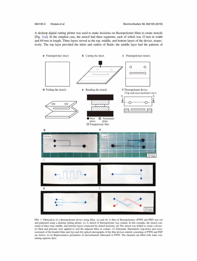
A desktop digital cutting plotter was used to make incisions on fluoropolymer films to create stencils[Fig. 1(a)]. In the simplest case, the stencil had three segments, each of which was 23 mm in widthand 69mm in length. Three layers served as the top, middle, and bottom layers of the device, respec-tively. The top layer provided the inlets and outlets of fluids; the middle layer had the patterns of
FIG. 1. Fabrication of a fluoropolymer device using films. (a) and (b) A film of fluoropolymers (PTFE and FEP) was cutand patterned using a desktop cutting plotter. (c) A stencil of fluoropolymer was created. In this example, the stencil con-sisted of three (top, middle, and bottom) layers connected by dotted incisions. (d) The stencil was folded to create a device.(e) Heat and pressure were applied to seal the adjacent films in contact. (f ) Schematic illustrations (top-down and cross-sectional) of the bonded films and [(g) and (h)] optical micrographs of the film devices entirely consisting of PTFE and FEPare shown. (i)–(l) Representative geometries of microchannels fabricated in PTFE. The channels are filled with water con-taining aqueous dyes.
064105-3 Hizawa et al. Biomicrofluidics 12, 064105 (2018)
microchannels; the bottom layer was without any incision and provided the bottom surface of thechannel. To facilitate aligning different layers, we designed all three segments of the device in asingle piece of the film; the adjacent segments were connected by dotted incisions (designed asdotted lines in the CAD file). These dotted incisions aided to fold the films and aligned the fluidopenings with the channel. We folded the stencil in zig zag pattern [Fig. 1(b)]. The arrangement inzig zag pattern was to avoid the misalignment of different layers due to the thickness of the film.Subsequently, heat and pressure were applied to the folded construct to bond the surfaces that were incontact [Fig. 1(c)]. After heat press, the device was ready for use. A schematic illustration of thecross-sectional view of the assembled device is given in Fig. 1(d). Assembly of the microchannels inPTFE and FEP was confirmed using blue ink [Figs. 1(e) and 1(f)]. Optical micrographs showed thatthe device was free of leakage. Using this method, we fabricated the microchannels with representa-tive geometries such as a T-junction and a flow-focusing nozzle [Figs. 1(i)–1(l)]. We note that thismethod can be readily extended for the fabrication of 3D microchannels using additional layers ofthe fluoropolymer film [Fig. 1(l)]. Microchannels with multiple inlets, branches, and intersections canbe fabricated in this method, which would be difficult to achieve by simply combining Teflon tubes.
Optimization of the conditions for heat press
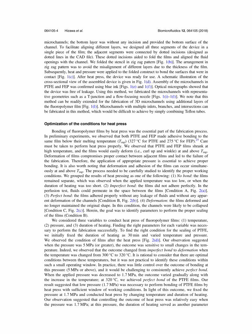
Bonding of fluoropolymer films by heat press was the essential part of the fabrication process.In preliminary experiments, we observed that both PTFE and FEP made adhesive bonding to thesame film below their melting temperature (Tmp) (327 °C for PTFE and 275 °C for FEP).25 Caremust be taken to perform heat press properly. We observed that PTFE and FEP films shrank athigh temperature, and the films would easily deform (i.e., curl up and winkle) at and above Tmp.Deformation of films compromises proper contact between adjacent films and led to the failure ofthe fabrication. Therefore, the application of appropriate pressure is essential to achieve properbonding. It is also worth noting that deformation and adhesion of the films can occur simultane-ously at and above Tmp. The process needed to be carefully studied to identify the proper workingconditions. We grouped the results of heat pressing as one of the following: (1) No bond: the filmsremained separate, which was observed when the applied temperature was too low, or when theduration of heating was too short. (2) Imperfect bond: the films did not adhere perfectly. In theperfusion test, fluids could permeate in the space between the films [Condition A, Fig. 2(a)].(3) Perfect bond: the films adhered properly without any leakage of fluids and without any appar-ent deformation of the channels [Condition B, Fig. 2(b)]. (4) Deformation: the films deformed andno longer maintained the original shape. In this condition, the channels were likely to be collapsed[Condition C, Fig. 2(c)]. Herein, the goal was to identify parameters to perform the proper sealingof the films (Condition B).
We considered three variables to conduct heat press of fluoropolymer films: (1) temperature,(2) pressure, and (3) duration of heating. Finding the right parameters for each variable was neces-sary to perform the fabrication successfully. To find the right condition for the sealing of PTFE,we initially fixed the duration of heating as 30 min and varied temperature and pressure.We observed the condition of films after the heat press [Fig. 2(d)]. Our observation suggestedwhen the pressure was 5MPa (or greater), the outcome was sensitive to small changes in the tem-perature. Indeed, we observed that the outcome changed from imperfect bond to deformation whenthe temperature was changed from 300 °C to 320 °C. It is rational to consider that there are optimalconditions between these temperatures, but it was not practical to identify these conditions withinsuch a small operating window. In practice, there was little control over the outcome of bonding atthis pressure (5 MPa or above), and it would be challenging to consistently achieve perfect bond.When the applied pressure was decreased to 1.7 MPa, the outcome varied gradually along withthe increase in the temperature; at 320 °C, we achieved perfect bond of the PTFE films. Ourresult suggested that low pressure (1.7 MPa) was necessary to perform bonding of PTFE films byheat press with sufficient window of working conditions. In light of this outcome, we fixed thepressure at 1.7 MPa and conducted heat press by changing temperature and duration of heating.Our observation suggested that controlling the outcome of heat press was relatively easy whenthe pressure was 1.7 MPa; at this pressure, the duration of heating served as another parameter
064105-4 Hizawa et al. Biomicrofluidics 12, 064105 (2018)
(in addition to temperature) to control the outcome state from imperfect bond to perfect bond forPTFE. For the identification of ideal bonding parameters, it was necessary to identify the condi-tion of one parameter with which the system can vary gradually (i.e., P = 1.7 MPa). For adhesivebonding of PTFE films, our observation suggested that lowering the operating pressure wasessential to understand and control the outcome of the bonding. We investigated the operationparameters for the bonding of FEP films in similar manners by fixing the applied pressure. Heatpress performed at 1.7 MPa, at 240 °C, and for 10 min resulted in perfect bond of FEP films tofabricate microfluidic channels without leakage. We demonstrated that both fluoropolymers wereapplicable for the fabrication of microchannels using the heat press. Both materials exhibit theresistance to organic solvents. FEP is optically transparent and suitable to create microchannelsthat require observations under an optical microscope.
Delamination of the films
Appropriate bonding between the fluoropolymer films is a key requirement for the fabricationof microchannels. We performed a delamination test to ensure the strength of the bonding. Thesetup of the experiment is illustrated in the supplementary material (Fig. S1). Briefly, we applied avariable pressure to the closed microchannel fabricated using this method. We increased theapplied pressure from 0 kPa at the increment of 50 kPa. We did not observe the delamination ofthe films at 300 kPa (∼3 atm). Further increase in the pressure caused the leakage of the fluid at theinlet of the channel (i.e., the interface between the syringe and the film). We note that the presentedmethod of film bonding was performed on the laboratory benchtop, not in the clean room. In suchconditions, uncontrolled encapsulation of small dust particles could occur. The fabricated devicenevertheless remained sealed at least at 300 kPa. Because 300 kPa would be sufficiently high to
FIG. 2. Representative outcome of the bonding of fluoropolymer films. (a)–(c) The outcomes of bonding were grouped intothree categories: Imperfect bond (Condition A), Perfect bond (Condition B), and Deformation (Condition C). Optimizationof the condition for the heat press: (d) Initially, the heat press was performed for a constant duration of time (30 min) with avariation of pressure (P) and temperature (T). This study suggested that the outcome was sensitive to the change in pressure.(e) Under the fixed pressure (P), the heat press was tested with a variation of time (t) and temperature (T). Overall, the condi-tion of (P, T, t) = (1.7MPa, 320 °C, 30 min) for the bonding of PTFE films.
064105-5 Hizawa et al. Biomicrofluidics 12, 064105 (2018)
deliver fluids with moderate viscosity (such as water, hydrocarbons, and fluorocarbons) throughthe channel on the order of 100 μm, we concluded that the proposed method of bonding providedappropriate sealing for our intended applications.
Dimension of the fabricated channels
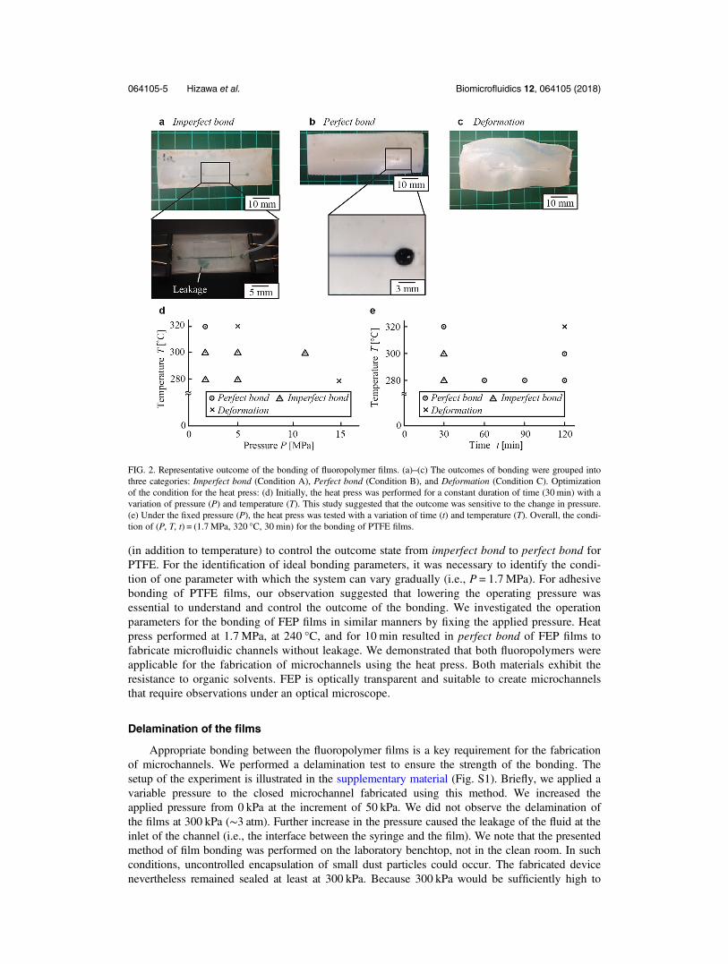
Adhesive bonding by heat press inevitably results in changes in channel dimensions.We chose the thickness of films as 200 μm for PTFE and 150 μm for FEP to ensure the opening ofthe channel without collapse after heat press and measured the widths of crossing microchannelsbefore and after heat press. Optical micrographs of the PTFE stencils and channels, which corre-spond to patterns before and after heat press, respectively, are shown [Fig. 3(b)]. The bonding wasperformed at 1.7MPa and 320 °C for 30 min.
We observed variations in the channel widths that were inherent to the desktop cutting plotterused in the experiment [Fig. 3(a)]. The cutting plotter could create incisions with an average width of250 μm. After heat press, the width of the resulting channels became smaller than the original widthby 200 to 300 μm. When the original width was 250 μm, the channels were collapsed [Fig. 3(b), top].
FIG. 3. (a) A plot showing the relationship between the designed width (td) and the actual width (ta) of the straight segmentof the PTFE channel (film thickness = 200 μm). (b) Representative optical micrographs showing the changes in the dimen-sion of the channels by heat press. The opening in a stencil was fully collapsed after the heat press for the channels with td= 250 μm, while the change was not as prominent for the channels with td = 1000 μm. (c) Optical micrographs showing thecross sections of the channels formed using this method of fabrication for PTFE (film thickness = 200 μm) and FEP films(film thickness = 150 μm). Each device was created by sealing three layers of the same films by heat press.
064105-6 Hizawa et al. Biomicrofluidics 12, 064105 (2018)
The change in the dimension of the channel was more pronounced for narrow incisions (250 μm) thanfor wide incisions (1000 μm). This difference can be attributed to the different aspect ratio of themicrochannels. In the current experiment, the thickness of the PTFE films was fixed as 200 μm,which was the primary factor to determine the height of the channel. The aspect ratio (defined aswidth divided by height) of the channel (before heat press) increased along with the increase in thechannel width. We believe that the smaller aspect ratio of the narrower channels would lead to thelarger deformation in horizontal dimensions because the pressure was applied from the vertical direc-tions. It is also worth mentioning that the decrease in the dimensions was isotropic in all horizontaldirection by heat press, suggested by the optical micrographs of the micropatterns [Fig. 3(b)].
In the related work by Wu et al., bonding two Teflon surfaces was achieved by exploitingvolume expansion of Teflon at high temperature.19 The change in the lateral dimension of channelswas not reported in that work. The difference is likely to be explained by the required bonding pres-sure. As the preceding work used replica molding on an SU-8 patterned silicon wafer to transfer pat-terns to Teflon, the resulting surface should be smoother than the films used in our current study. The
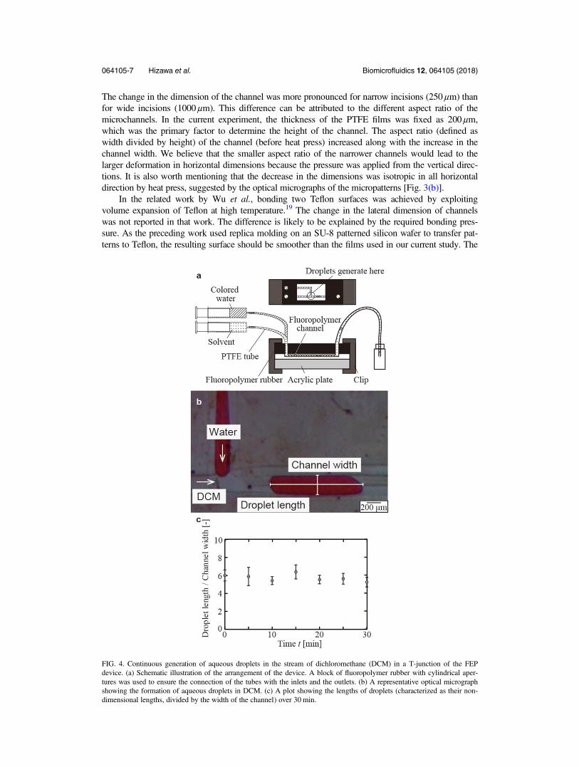
FIG. 4. Continuous generation of aqueous droplets in the stream of dichloromethane (DCM) in a T-junction of the FEPdevice. (a) Schematic illustration of the arrangement of the device. A block of fluoropolymer rubber with cylindrical aper-tures was used to ensure the connection of the tubes with the inlets and the outlets. (b) A representative optical micrographshowing the formation of aqueous droplets in DCM. (c) A plot showing the lengths of droplets (characterized as their non-dimensional lengths, divided by the width of the channel) over 30 min.
064105-7 Hizawa et al. Biomicrofluidics 12, 064105 (2018)
lower surface roughness would require the lower bonding pressure by heat press. Our current workused commercially available fluoropolymer films as purchased; the roughness of the film was not con-trolled, which may result in the requirement of a certain pressure to achieve bonding the films.
Solvent resistance of fluorinated channels
Fluoropolymers are known to exhibit resistance to solvents; they do not swell and dissolvewhen they are exposed to a wide range of solvents that would not be compatible with PDMS.18,21
We experimentally validated solvent resistance of microchannels made of FEP and PTFE. To dem-onstrate the solvent resistance of FEP, T-junction microchannels consisting of FEP films weretested for continuous generation of aqueous droplets in dichloromethane (DCM). DCM was usedas a continuous phase directly in contact with the main channel. If the DCM was not compatiblewith the device, either the device would not maintain its original structure (by dissolving or swelling)or the performance of droplet formation would be compromised. For example, swelling of the
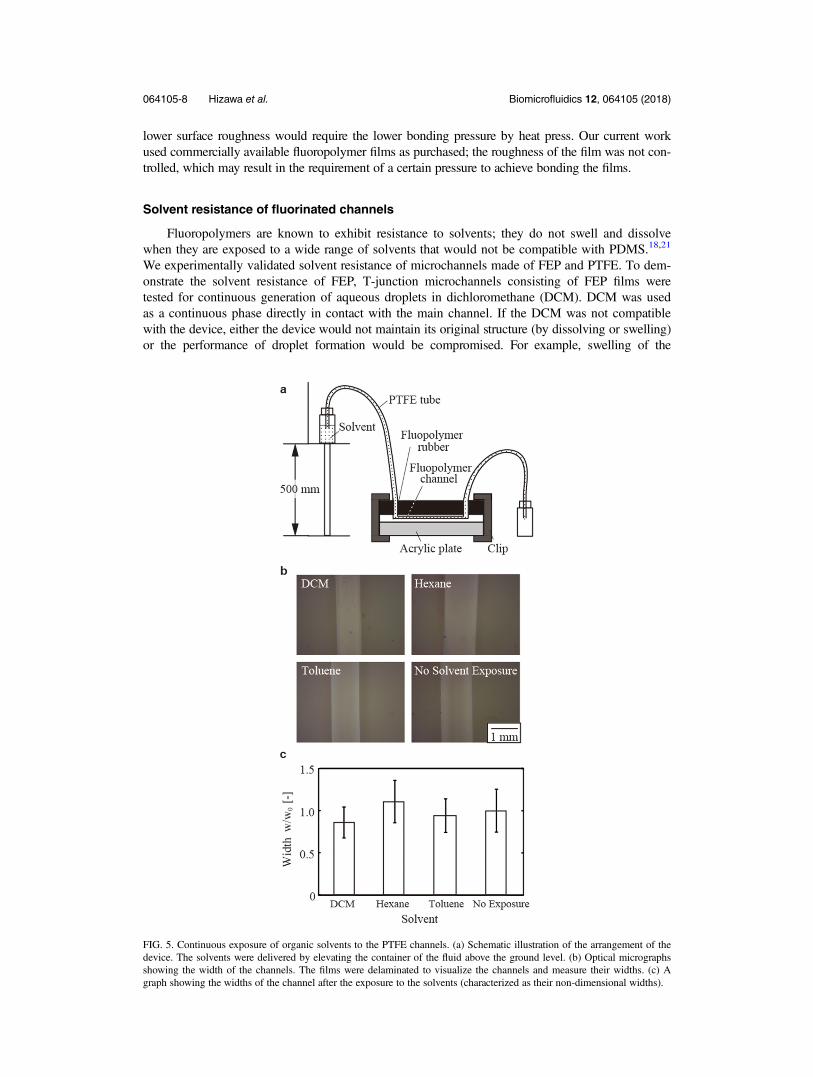
FIG. 5. Continuous exposure of organic solvents to the PTFE channels. (a) Schematic illustration of the arrangement of thedevice. The solvents were delivered by elevating the container of the fluid above the ground level. (b) Optical micrographsshowing the width of the channels. The films were delaminated to visualize the channels and measure their widths. (c) Agraph showing the widths of the channel after the exposure to the solvents (characterized as their non-dimensional widths).
064105-8 Hizawa et al. Biomicrofluidics 12, 064105 (2018)
channel would alter the apparent size of plug-shaped droplets in the channel. The setup of the experi-ment is illustrated [Fig. 4(a)]; glass syringes, PTFE tubes, and PTFE rubber blocks were used todeliver the fluid to the device. The tubing was held in the holes created in a PTFE rubber (with adiameter of 1 mm). To avoid leakage of the fluids, the pieces of PTFE rubber were manually forcedto stay in conformal contact with the inlets and outlets of fluids on the film. We generated drop-lets of distilled water in a channel filled with DCM; the flow rates of distilled water and DCMwere 150 μl/min and 50 μl/min, respectively. We observed the generation of droplets continuously for30min, and the in-channel length of the droplet was measured every 5 min [Figs. 4 (b) and 4(c)].The length of the formed droplets (along the direction of the flow, scaled by the width of thechannel) remained constant within their standard deviations. This observation suggested that thedevice entirely consisting of FEP is resistant to DCM.
PTFE is an opaque material. While solutions with dark colors can be observed through it, themeasurement of the droplet sizes by optical images was not reliable through PTFE. To validate thesolvent resistance of PTFE channels, the width of the channels was measured after the exposure tosolvents, and it was compared with the width of the channels of the same design without exposureto the solvents. We perfused three solvents (i.e., DCM, hexane, and toluene) through the channelsfor at least 6 h [Fig. 5(a)]. After the perfusion, the device was forced to delaminate, and the result-ing width of the channels was measured [Fig. 5(b)]. The width of the channels (where the widthwas designed to be 750 μm in the CAD file) remained unchanged after the exposure to all threeorganic solvents [Fig. 5(c)]. Observed variations of the channel width were attributed to the preci-sion of manufacturing by the cutting plotter we used. Within these errors (defined as the standarddeviation, n = 4), we concluded that there was no change in the width of channels by the exposureto the three organic solvents that were tested. While we tested a set of three solvents for two typesof fluoropolymers, chemical compatibility of fluoropolymers has been well-studied.21 We con-cluded that the solvent compatibility conferred by the property of fluoropolymers was retained aftersealed microchannels were fabricated.
CONCLUSION
We developed a method for rapid prototyping of microchannels consisting of fluoropolymersusing xurography and heat press. A cutting plotter was used to create stencils of fluoropolymerfilms, and heat press was used to laminate them to form microfluidic devices entirely consisting offluoropolymer. We identified the conditions for heat press for two common fluoropolymers, polyte-trafluoroethylene (PTFE) and fluorinated ethylene propylene (FEP), and the fabricated deviceswere shown to exhibit good compatibilities to selected organic solvents including dichloromethanewith which thermoplastics and photocurable polymers were largely incompatible.
Microchannels consisting of PDMS can be readily prototyped by soft lithography, but they canbe problematic for certain applications using organic solvents. On the other hand, fluoropolymersexhibit great solvent compatibility, but to date rapid and facile prototyping methods have not beendeveloped. This work is the first demonstration to bridge those gaps by applying xurography and heatpress. The developed method is simple, rapid, and low-cost. The entire fabrication can be completedin less than 1 h using commercially available fluoropolymer films and a desktop cutting plotter.Microchannels consisting of fluoropolymers can be useful in performing organic syntheses of materi-als and drugs26,27 as well as regulating adhesion of biological molecules, cells, and bacteria.28,29 Webelieve that xurography and heat press of PTFE and FEP films offer a new avenue to prototype micro-channels for various applications that require the inert and non-reactive properties of the channels.
EXPERIMENTAL SECTION
Fabrication of microfluidic devices
Films of polytetrafluoroethylene (PTFE) (200-μm thick, Monotaro, Amagasaki, Japan) andfluorinated ethylene propylene (FEP) (150-μm thick, Shenzhen Forbest Technology Co. Ltd.,China) were patterned using a desktop cutting plotter (Silhouette CAMEO 2, Silhouette America,
064105-9 Hizawa et al. Biomicrofluidics 12, 064105 (2018)
Inc., UT, USA). An adhesive cutting mat (CAMEO Cutting Mat, Silhouette America, Inc., UT,USA) was used to hold the fluorinated films during cutting. Adhesive materials were transferredfrom the cutting mat to the fluoropolymer films. The fluorinated film was cleaned with ScotchMagic Tape (3M, MN, USA) and washed with running water for 30 s. The stencil was foldedalong the fold lines as designed. The fold stencil was placed between two 150 × 100 mm2 alumin-ium plates. Heat and pressure were applied with a heat press instrument (4386, CARVER, IN,USA). The successful bonding was achieved for FEP (at 1.7 MPa and 240 °C for 10 min) andPTFE (at 1.7 MPa and 320 °C for 30 min).
Delamination of bonded fluoropolymer films
A setup to study the delamination of the bonded fluoropolymer films is shown [Fig. S1(a) inthe supplementary material]. A pressure controlled, fluid dispenser (MS-1, Musashi Engineering,Inc., Tokyo, Japan) was used to apply the pressure to the closed microchannel filled with coloredwater. The discharge pressure of the colored water was measured using a pressure sensor(PSAN-L1CV, Autonics Corp., Busan, Korea) connected in parallel to the dispensing syringe. Forboth PTFE and FEP, the device was fabricated as described. The pattern of the channel was straight(width 500 μm, length 20 mm) with one inlet and no outlet to study the delamination of the filmsupon the applied pressure [Fig. S1(c) in the supplementary material]. The channel was fully filledwith the colored water before applying the pressure. Introduction of colored water was carried outby placing a droplet of the colored water on the inlet of the fluoropolymer channel using a syringeand degassed with a desiccator (0.2 MPa, 10 min). After the channel was fully filled with thecolored water, the syringe needle integrated with the rubber seal was placed above the inlet of thefluoropolymer channel. The digitally controlled dispenser applied the pressure (0, 50, 100, 150,200, 250, and 300 kPa) to the syringe connected to the inlet of the device for 10 s. After applyingeach pressure, the fluoropolymer channel was optically examined for delamination and photo-graphed with a single lens reflex camera (D-5300, Nikon Corp., Tokyo, Japan).
Imaging
The fabricated devices and fluidic experiments were imaged and observed using a microscope(MU500, AmScope, CA, USA).
Fluidic experiments
The sealed microfluidic device was placed between two fluoropolymer rubber blocks (3-mmthick, Monotaro, Amagasaki, Japan) with manually punctured cylindrical apertures (1-mm diame-ter) for connection to tubes. The fluoropolymer rubber blocks were clipped to the film device toavoid leakage of the solvents at the inlet. The device was connected to 10-ml glass syringes(Sigma-Aldrich, Hamilton Syringes, Singapore) with PTFE tubes (EW-06417-21, OD = 1.06 mm,Cole-Parmer, IL, USA). Syringe pumps (NE-4000, New Era Pump Systems, Inc., NY, USA) wereused to deliver fluids for the experiments in droplet generation in the FEP devices. Elevation of thefluid containers (500 mm above the height of the device) was used to provide the pressure differ-ence to deliver the fluids for continuous flow experiments in the PTFE devices. All solvents(dichloromethane, hexane, and toluene) were used as purchased (Sigma-Aldrich, Singapore). Waterwas coloured with food dye (Liquid Artificial Apple Green Colour, Tesco PLC, Star Brand,Welwyn Garden City, UK) for visualization.
SUPPLEMENTARY MATERIAL
An additional figure was provided as a supplementary material to illustrate the details of theexperiments.
064105-10 Hizawa et al. Biomicrofluidics 12, 064105 (2018)
ACKNOWLEDGMENTS
T.H. and E.I. thank the Top Global University Project at Waseda University, supported by theMinistry of Education, Culture, Sports, Science and Technology (MEXT) in Japan. H.M. thanksStart-up Research Grant (No. SREP14088) at Singapore University of Technology and Design forthe financial support. P.P. thanks the SUTD-MIT postdoctoral fellowship program.
1Y. Xia and G. M. Whitesides, Annu. Rev. Mater. Sci. 28, 153–184 (1998).2D. C. Duffy, J. C. McDonald, O. J. Schueller, and G. M. Whitesides, Anal. Chem. 70, 4974–4984 (1998).3L. Téllez, J. Mater. Sci. 38, 1773–1780 (2003).4Q. Xu, M. Hashimoto, T. T. Dang, T. Hoare, D. S. Kohane, G. M. Whitesides, R. Langer, and D. G. Anderson, Small 5,1575–1581 (2009).
5D. Huh, Y. S. Torisawa, G. A. Hamilton, H. J. Kim, and D. E. Ingber, Lab Chip 12, 2156–2164 (2012).6L. Mazutis, J. Gilbert, W. L. Ung, D. A. Weitz, A. D. Griffiths, and J. A. Heyman, Nat. Protoc. 8, 870–891 (2013).7P. M. Valencia, E. M. Pridgen, M. Rhee, R. Langer, O. C. Farokhzad, and R. Karnik, ACS Nano 7, 10671–10680 (2013).8J. J. Lee, K. J. Jeong, M. Hashimoto, A. H. Kwon, A. Rwei, S. A. Shankarappa, J. H. Tsui, and D. S. Kohane, Nano Lett.14, 1–5 (2014).
9C. W. Shields, C. D. Reyes, and G. P. Lopez, Lab Chip 15, 1230–1249 (2015).10R. Mukhopadhyay, Anal. Chem. 79, 3248–3253 (2007).11R. J. Jackman, T. M. Floyd, R. Ghodssi, M. A. Schmidt, and K. F. Jensen, J. Micromech. Microeng. 11, 263–269 (2001).12E. Piccin, W. K. Coltro, J. A. Fracassi da Silva, S. C. Neto, L. H. Mazo, and E. Carrilho, J. Chromatogr. A 1173,151–158 (2007).
13D. Bartolo, G. Degre, P. Nghe, and V. Studer, Lab Chip 8, 274–279 (2008).14C. F. Carlborg, T. Haraldsson, K. Oberg, M. Malkoch, and W. van der Wijngaart, Lab Chip 11, 3136–3147 (2011).15M. Hashimoto, R. Langer, and D. S. Kohane, Lab Chip 13, 252–259 (2013).16V. Arcella, A. Ghielmi, and G. Tommasi, Ann. N.Y. Acad. Sci. 984, 226–244 (2003).17W. R. Dolbier, J. Fluor. Chem. 126, 157–163 (2005).18C. T. Riche, C. Zhang, M. Gupta, and N. Malmstadt, Lab Chip 14, 1834–1841 (2014).19K. Ren, W. Dai, J. Zhou, J. Su, and H. Wu, Proc. Natl. Acad. Sci. U.S.A. 108, 8162–8166 (2011).20J. P. Rolland, R. M. Van Dam, D. A. Schorzman, S. R. Quake, and J. M. DeSimone, J. Am. Chem. Soc. 126, 2322–2323(2004).
21O. Cybulski, S. Jakiela, and P. Garstecki, Lab Chip 16, 2198–2210 (2016).22D. A. Bartholomeusz, R. W. Boutte, and J. D. Andrade, J. Microelectromech. Syst. 14, 1364–1374 (2005).23L. Renaud, D. Selloum, and S. Tingry, Microfluid. Nanofluid. 18, 1407–1416 (2015).24A. Neuville, L. Renaud, T. T. Luu, M. W. Minde, E. Jettestuen, J. L. Vinningland, A. Hiorth, and D. K. Dysthe, Lab Chip17, 293–303 (2017).
25A. Taberham, M. Kraft, M. Mowlem, and H. Morgan, J. Micromech. Microeng. 18, 064011 (2008).26P. D. I. Fletcher, S. J. Haswell, E. Pombo-Villar, B. H. Warrington, P. Watts, S. Y. F. Wong, and X. Zhang, Tetrahedron58, 4735–4757 (2002).
27P. Watts and S. J. Haswell, Chem. Soc. Rev. 34, 235–246 (2005).28H. Lu, L. Y. Koo, W. M. Wang, D. A. Lauffenburger, L. G. Griffith, and K. F. Jensen, Anal. Chem. 76, 5257–5264(2004).
29E. W. Young, A. R. Wheeler, and C. A. Simmons, Lab Chip 7, 1759–1766 (2007).
064105-11 Hizawa et al. Biomicrofluidics 12, 064105 (2018)