Rapid Prototyping & Manufacturing Technologies
34
IC LEARNING SERIES Rapid Prototyping & Manufacturing Technologies
-
Upload
shameka-rivera -
Category
Documents
-
view
216 -
download
2
Transcript of Rapid Prototyping & Manufacturing Technologies

IC LEARNING SERIES
Rapid Prototyping & Manufacturing
Technologies

The Hong Kong Polytechnic UniversityIndustrial Centre
IC LEARNING SERIES
Rapid Prototyping & Manufacturing TechnologiesSuitable for the following learning modules offered by the Industrial Centre:
TM0203 Use of Plastics in Our SocietyTM0205 Plastics Technology Practice and Metal Surface FinishingTM4001 Integrated Training I for ME DG StudentsTM4009 Integrated Training for ISE DG StudentTM4011 Integrated Training for PIT HD StudentTM4012 Integrated Training II for PIT HD Student

Rapid Prototyping & Manufacturing Technologies
Page 1 IC Professional Training
Objectives:
To understand the importance and applications of rapid prototyping and manufacturing (RP&M) technologies in the product design and development processes.
To understand the general function of prototype in the product design and development process.
To appreciate the common types of rapid prototyping systems. To understand the basic steps in RP process. To learn the basic of Rapid Tooling process.
1. Introduction
In recent years, opening up local markets for worldwide competition has led to a fundamental change in new product development (NPD). In order to stay competitive, manufacturers should be able to attain and sustain themselves as "World Class Manufacturers". The manufacturers should be capable in delivering products in fulfilling the total satisfaction of customers, products in higher quality, short delivery time, at reasonable costs, environmental concern and fulfill all the safety requirements.
In many fields, there is great uncertainty as to whether a new design will actually do what is desired. New designs often have unexpected problems. A prototype is often used as part of the product design process to allow engineers and designers the ability to explore design alternatives, test theories and confirm performance prior to starting production of a new product. Engineers use their experience to tailor the prototype according to the specific unknowns still present in the intended design.
Rapid Prototyping technology employ various engineering, computer control and software techniques including laser, optical scanning, photosensitive polymers, material extrusion and deposition, powder metallurgy, computer control, etc. to directly produce a physical model layer by layer (Layer Manufacturing) in accordance with the geometrical data derived from a 3D CAD model. RP can deliver working prototype at the early design stage of the new product cycle. So manufacturers can use the working prototypes in bridging a multi-disciplined
RRaappiidd PPrroottoottyyppiinngg && MMaannuuffaaccttuurriinngg TTeecchhnnoollooggiieess

Rapid Prototyping & Manufacturing Technologies
Page 2 IC Professional Training
team composed of the marketing, design, engineering and manufacturing people to design right at the first instance in catering for the customers.
Rapid prototyping (RP) is rapid creation of a physical model. However, rapid prototyping is slowly growing to include other areas. So, Rapid Prototyping, Tooling and Manufacturing (RP&M) should be used to include the utilization of the prototype as a master pattern for tooling and manufacturing.
1.1 Types of prototype for NPD
Before getting involves to the topic of RP&M, the fundamental concepts and applications of prototypes should be obtained. Prototypes that will be required in the product design and development process are commonly divided into the following types.
• 3D sketches • Cosmetic prototypes • Engineering / Functional prototypes • Samples for safety approval • Marketing Samples
1.1.1 3D sketches
Traditionally product designer use foam, cardboard, clay or wood to make quick models. The designers may generate a lot of simple model a day to visualize different ideas. They also interchange portions of different models by cut and paste, or reshape the model to explore different possibility. Since it is the early stage of the project, usually the models are not presented to outside clients, therefore colors and textures and surface finishing are not an issue.
Among various RP technologies, Multi-jet Modeling (MJM) and 3D-printing (3DP) technologies is most suitable for 3D sketches not only because they are faster, but also because they are less expensive and the models are easier to reshape.
1.1.2 Cosmetic prototypes
As the name implied, the prototypes are used to evaluate the appearance and feeling of the design, and get early comments from potential clients. Apart from solid and non-functional, cosmetic prototypes are the same as finished product in aspect, such as shape, color, texture and hardness.
Most RP technologies can be used for cosmetic prototypes. However, those with better post-processing properties will have a competitive edge because a lot of polishing and painting will be applied on the model. In this perspective, SLA & MJM are easier to polish because of its smooth surface. FDM is more difficult because the part have to be cover with a layer of putty. SLS and LOM are among the most difficult, due to the tough nylon material and fiber strands of paper. 'Concept modelers' is the choice where time is the most critical concern. These include droplet deposition systems such as InVision, Objet and ZCorp's machine.

Rapid Prototyping & Manufacturing Technologies
Page 3 IC Professional Training
1.1.3 Engineering / Functional prototypes
In engineering development, Engineers will evaluate the form, fit and function of the parts. The prototype will use the same material of the final product if technology permitted. If exact material is not available, the materials with similar mechanical, thermal and electrical properties are used. The SLS and FDM allow the use of production grade plastic material, although the mechanical properties are not exactly the same.
1.1.4 Samples for safety approval
For those products that are regulated by safety standards of importing country, at lease 5-10 product samples have to be submitted to the laboratory for each application. If pilot run of the product is ready, the finish products will be submitted. However, in most case the project is still in tooling stage, and samples by PU duplication may be used if the laboratory accepts. 5 to 10 duplicates can be produced in a day. PU duplicate cannot be used as substitution if the part under consideration is subjected to high temperature, voltage and mechanical abuse. In this Rapid Tooling techniques can be used. Manufacturers have a choice to quickly build a mould and produce a small batch of sample parts in actual production material.
1.1.5 Marketing Samples
At a later stage when all design details are finalized and the project is in tooling stage, the marketing department will start the promotion campaign. A lot of samples may be distributed to clients. In this case, up to a hundred products may be needed. Normally the samples will be made by RTV mould and PU duplication technique. In many cases, these models are also used to take the picture that appears in the package box or user manual.
1.2 Differences between conventional machining and rapid prototyping
Conventional machining can produce prototypes using metal removal method with almost any type of engineering materials however there are only a limited type of materials for any particular type of RP&M systems. RP&M systems are usually used for making one or a few sample of prototype, while the number of prototype produced in conventional machining can be adjusted as required. The basic working principle of RP technologies is totally different from conventional machining processes which build up a solid by mean of addition approach like construction of the building. Hence the RP also started from foundation then gradually increase in height until it reached the top layer.

Rapid Prototyping & Manufacturing Technologies
Page 4 IC Professional Training
Fig. 1.1 Differences between conventional machining and rapid prototyping
1.3 Why RP&M
The application of the RP&M in the NPD can resolves the Fuzzy Front End – the messy getting started period of NPD process - would be relatively costly and timely. However using RP&M enable manufacturers to schedule the right product being developed in a timely manner is the most important winning strategy. The combination of the RP&M and CAD technologies in blending with traditional technologies and gradually formation of cross-functional team are the strategies for survival or strategies for empowering organization, people and facilities. 1.4 Limitations of RP&M
High precision RP machines are still expensive at around US$ 100 thousands to 1 million and not easy to justify economically and many service bureaus in providing the physical prototypes output services. However, as the RP technologies are getting more mature while RP manufacturers are facing more head-to-head competition, the price will go down significantly in the near future such as the launch of V Flash priced at US$ 10 thousands. Most of the budget RP systems are difficult to build parts with accuracy under +/-0.02mm and wall thickness under 0.5mm. This is sufficient for prototypes built for concept evaluation and functional test.
However, prototypes that will be used as master pattern for downstream processes always require a much higher and consistent accuracy. Although there are quite a large variety of materials that can be used in most RP processes, the physical properties of the RP parts are normally inferior to those samples that made in proper materials and by the traditional tooling. The RP parts are not comparable to traditional Computer Numerical Control machined (CNC) prototype parts in the surface finishing, strength, elasticity, reflective index and other material physical properties.

Rapid Prototyping & Manufacturing Technologies
Page 5 IC Professional Training
1.5 The future market profile of RP&M systems
The future market profile of the rapid prototyping/manufacturing industry will have two specific niches. The first one will be focused on Digital Direct Manufacturing (DDM) of engineering parts for not only testing form fit, functional evaluation, but also can be directly used in products. The second niche will be looking at the market requirement in another point of view. It will focus on concept modeling or 3-Dimensional printing for design verification, preliminary marketing tool and manufacturability studies. In this case, the most important considerations are speed and low cost. The accuracy and resolution requirement is minimal so far it can provide the designer a reasonable representation of the design.
2. Common Types of Rapid Prototyping Technologies
While there are many ways in which one can classify the numerous RP systems in the market, one of the better ways is to classify RP systems broadly by the initial form of its material, i.e. the material that the prototype or part is built with. In this manner, all RP systems can be easily categorized into (1) liquid-based (2) solid-based and (3) powder-based.
Liquid-based RP systems have the initial form of its material in liquid state. Through a process commonly known as curing, the liquid is converted into the solid state. The Stereolithography Apparatus (SLA) falls into this category.
Solid-based RP systems encompass all forms of material in the solid state. In this context, the solid form can include the shape in the form of wire, roll, laminates, pellets and powders. The Selective Laser Sintering (SLS), Three-Dimensional Printing (3DP) Fused Deposition modeling (FDM) fall into this definition. 2.1 Stereolithography Apparatus (SLA) – Liquid based RP
Stereolithography Apparatus (SLA) technology fabricates three-dimensional, solid objects resin using a computer-directed, ultraviolet (UV) laser beam to cure successive layers of photo-sensitive polymer resin in a vat.
SLA part is fabricated by laser spot instead of continues scanning on the resin which forms a thin solid layer on the surface of the liquid resin through the photopolymerization. Figure 2.1 shows the schematic diagram of this spot scanning mechanism.
Polymerization is the process of linking monomers and oligomers into larger molecules (polymers). When photoinitiators in the SLA resin are energized by the laser spot energy exposure (Ec value in mJ/cm2) will undergoes the photopolymerization process. It creates a thin layer of solid resin with thickness about 2-3 times thicker than the layer thickness (overcure). The total thickness of

Rapid Prototyping & Manufacturing Technologies
Page 6 IC Professional Training
the layer is depending on the scanning speed of the laser and the Depth penetration factor of the resin (Dp value in mm).
Fig. 2.1 Schematic diagram of SLA laser processing mechanism
2.1.1 Processes Description
In SLA process, the software firstly interprets and pre-process the CAD data and slices it into a series of thin horizontal layers and converted to machine specified control data files based on the part, building and recoating parameters. The machine control data is then downloaded into the equipment for part building. A perforated stainless steel building platform attached to a vertical elevator is moved to the start position which is just below the resin surface.
An X-Y electronic motor driver optical scanning mirrors directs the laser beam, which cures the borders and cross sections of the built parts one layer at a time on the surface of the resin. Photopolymers are converted into solid state instantly after irradiation of laser beam
The elevator then lowers the newly built layer by a distance of one layer thickness after a short period of time to allow the newly formed layer to increase the green strength (pre-dip delay), the vacuum activated re-coater blade which is separated from the surface of the resin by a predetermined blade gap then coats a new layer of resin with thickness equal to the layer thickness on the newly formed solid layer, and the process is repeated until the object is completed.
The elevator then rises out of the resin surface and the object is removed from the vat for the post processing. Figure 2.2 shows a schematic diagram of SLA system.
Resin Surface

Rapid Prototyping & Manufacturing Technologies
Page 7 IC Professional Training
Fig. 2.2 Schematic diagram of stereolithography process
Fig. 2.3 Basic components of SLA system
2.1.2 SLA Material – Liquid Resin
A variety of resin is available for SLA, each with its own advantage and weakness. Typical SLA resins only react to a narrow bandwidth of UV ray, both Viper Si2 and SLA-3500 employs a Diode-pumped solid-state (DPSS) lasers Nd:YVO4 (Neodymium Yttrium Vanadate) as a energy source of polymerization. Generally, the resins need to be kept in an environment with tight temperature and humility
Laser – concentrative UV beam to transom liquid resin into solid state.
Elevator – control the movement of platform upward and upward in order to
Platform – a steel plate with plenty of holes as the basement for part building
Resin vat – contain raw material to form SLA model
Mirrors – control the path of movement of the laser beam at X and Y axis
Sensor – locate the coordinate and instant power of the laser beam and feedback to the control unit for fine adjustment
Sensor
Mirrors

Rapid Prototyping & Manufacturing Technologies
Page 8 IC Professional Training
control in ensuring the reaction conditions. For example, the chamber of SLA is maintained at 28°C ± 1°C.
Resins used in SLA process are mixture of photo-initiator, linkers, oligomers and monomer mixture in liquid state, photonic energy source will trigger the chain reaction of polymerization. Two parameters penetration depth (Dp) and critical exposure (Ec), which are vary from different resins, are as the primary input to the SLA machine for controlling the power and time of laser emission. The following illustrate the underlying principle of the two important parameters;
Penetration Depth (Dp) and Critical Exposure(Ec)
When a beam of light hit the resin surface, it will cure a region of resin in the shape of a bullet. The intensity of the beam determined the extent of reaction and the size of the bullet.
The threshold exposure, Ec, is the energy required for the photopolymer changes from the liquid to the gel phase. In the process, Dp and Ec is primary characters of the resin provided by manufacturer. The SLA machine determine PL and Vs on the fry by the relation that the draw speed of the laser Vs proportional to (PL/EC)exp(-Cd/Dp).
Cp Critical depth, given by the function Cd=Dpln(Emax/Ec)
Dp The depth of penetration which the
power of laser decay to approx. Emax/3 Emax The power of laser at resin surface Ec Critical Exposure, a primary resin
character, unit in mJ/cm2

Rapid Prototyping & Manufacturing Technologies
Page 9 IC Professional Training
Physical properties of SLA material available in IC
Accura 25 Accura 55 Accura 60 Accura Bluestone
Appearance White White Clear Opaque Blue
Penetration Depth(Dp)*
4.2mils 5.2mils 6.3mils 4.1mils
Critical Exposure(Ec)*
10.5mJ/cm2 7.4mJ/cm2 7.6mJ/cm2 6.9mJ/cm2
Tensile Strength 38MPa 63-68MPa 58-68MPa 66-68MPa
Elongation at Break(%)
13-20% 5-8% 5-13% 1.4-2.4%
@66PSI 58-63oC 55-58 oC 53-55 oC 65-66 oC
@264PSI 51-55 oC 51-53 oC 48-50 oC 65 oC
@66PSI with 120oC Thermal Postcure
267-284 oC
Hardness, Shore D 80 85 86 92
For more information about SLA material, please refer to 3D systems web site (http://www.3dsystems.com/)

Rapid Prototyping & Manufacturing Technologies
Page 10 IC Professional Training
2.1.3 Support Structure
Support usually need for liquid-based and solid-based RP systems in order to anchor the part to the platform hence the part can be separated from the platform thus preventing floating layers and make removal of the part became simple.
Also support is needed for overhanging and tilted surfaces hence minimize part curl and stabilize the part while being built. Self support angle is a predetermined angle for the particular SLA RP system such that tilted surfaces with this angle from the horizon needs no support.
The supported surfaces are the overhanging down face of the part. Since supports need to anchor the surface at the contact point. Hence the surfaces in contact with the support are rough and coated with resin gel after the part build completed. So do not place supports on surfaces where finish is important.
Fig. 2.4 SLA support structure, Left: curtain support. Right: fine-point support
Support can be classified according to the support structure and the type of surfaces being supported. Support types include solid, box, web and fine point supports. Besides supports classified according to the geometry of the down face include point, line and surface supports.
SLA uses Fine-point support style as the default support style, however when long and slender support is need then Curtain support style can be used to ensure the strength of the support while the prototypes are build in the vat. Figure 2.4 shows both SLA support styles.
2.1.4 Building Styles
The rapid prototyping systems usually bundled with software which can control the build styles, generate supports, slicing of the STL files and creating control file for building the prototype in the RP machine. There are Part build style, Support build style, Part Recoat style and the Support Recoat style in the SLA software called 3DLightyear.
Part build style controls the laser when drawing the part. Different part build style can produce part in different patterns which include the solid part – the exact build style, the hollow part for investment casting – Quickcast build style. The fast build style which shortens the build time of the part by filling the part in alternate layers.
Part Part
Projection
Stand

Rapid Prototyping & Manufacturing Technologies
Page 11 IC Professional Training
Support build styles control the laser when drawing the support. Curtain support or Fine point support can be created by choosing different support build styles in SLA building platform.
Part recoat styles controls the recoating process including the dipping depth and speed of the build platform and the speed and the number of recoats of the recoat blade.
Support recoat styles controls the recoating process while building the support. 2.2 Fused Deposition Modeling (FDM)
2.2.1 Processes description
Fused Deposition Modeling (FDM) was developed by Scott Crump, the founder of Stratasys. It was commercialized by Stratasys in 1991. FDM process create component by extruding material (normally a thermoplastic material) through a nozzle that traverses in X and Y to create each two-dimensional layer.
Heaters which surround two separated nozzles keep the plastic at a temperature just above its melting point so that it flows through the nozzle and forms the layer according to the tool path. In each layer separate nozzles extrude and deposit material that forms the parts and the support structure. The plastic hardens immediately after flowing from the nozzle and bonds to the layer below. Once a layer is built, the platform lowers, and the extrusion nozzle deposits another layer and the process is repeated until the object is completed. Figure 2.5 show a schematic diagram of FDM process.
Fig. 2.5 Schematic diagram of FDM processes

Rapid Prototyping & Manufacturing Technologies
Page 12 IC Professional Training
Support structure can be removed manually or, when water soluble supports are employed, they can be simply dissolved by put into particular chemical solution. However, soluble support is only available for building ABS model, other high melting point plastic material such as polycarbonate (PC) and polysulphone (PPSF) are not applicable.
2.2.2 FDM material
The build material is usually supplied in filament form with 1.8mm diameter, but the layer thickness and vertical dimensional accuracy is determined by the extrusion nozzle diameter and the rate of feeding of the building material, which ranges from 0.018 to 0.008 inches. In the X-Y plane, 0.001 inch resolution is achievable. Thermoplastic material is most often used which including Acrylonitrate Butadiene Styrene (ABS), Polycarbonate (PC), polysulphone (PPSF), and investment casting wax is designed for investment cast.
ABSi ABS-M30* PC-ABS PC* ULTEM9085
PPSF*
Appearance Ivory White Tan
Tensile Strength (MPa)
38 36 34.8 52 72 55
Tensile Modulus (MPa)
1993 2413 1827 2000 2220 2068
Flexural Strength (MPa)
59 61 50 97 115 110
Flexural Modulus (MPa)
1797 2317 1863 2137 2507 2206
Notched Izod Impact (J/m)
139 123 53.39 106 59
Heat deflection (oC)
95 96 326 127 153 189
Density g/cm2 ) 1.09 1.04 110 1.2 1.34 1.28
Elongation at Break (%)
>10 4 1.2 3 4 3
Support Structure
Soluble Soluble Soluble Bass Bass Bass
*Material Available in IC
Rapid Prototyping & Manufacturing Technologies
Page 13 IC Professional Training
2.2.3 Support Structure
Supports in the form of solid type or box type are usually required for the Solid-based RP system. Box type support is used in FDM. The support material used for FDM depending on the type of model mater used for making the prototype and can be classified into two main type – soluble support and break away support. The soluble support uses a "water-soluble" material which turns into liquid in an ultrasonic heating tank filled with hot (70 degree F) amino based water solution for 4 hours, the support is then dissolved in the tank. However the soluble support is only suitable for ABS grade model material as shown in the table above. Break away support is used for model material which melts at a higher temperature than ABS. Break away support need to be removed by hand tools upon the completion of the building of the prototype.
The self support angle of FDM is 45 degree and 4 types of support styles are available for the creation of support namely Basic support, Sparse support, Surround support and Break away support. The support curves can be created after the appropriate supports style is determined.
Basic supports will create supports under all part features that are exposed to air on the underside. The top layer of each support column will have a solid fill and the layers underneath will have a small air gap between toolpath passes. These passes are called the support raster curves. This type support is particular suitable for model with fine details in the down face however the build time is long and the more support material is used compared with the Sparse support.
Sparse supports will create supports that use less material than basic supports. This is accomplished by creating a new raster fill pattern that has a much larger air gap between raster. Like basic supports, the top layer of a support column is built with a solid pattern of raster. The next several layers have the basic raster pattern that has a small air gap. Progressing downward, a new sparse support region is used below the several layers of basic support raster fill. The sparse support regions use a much larger air gap when building the tool path raster. In addition, the region is surrounded by a single closed tool path-perimeter curve.
Surround supports are used to surround small features or parts that require few actual supports, but cannot stand upright on the platform during the part build. Surround supports will create the support tops just like basic supports but will also surround every layer of the model with a minimum thickness of supports.
Break-away supports are similar to sparse supports but consist of boxes instead of a continuous raster. There is no closed toolpath-perimeter curve around the break-away supports. They are easier to remove than other support styles for some materials but build slower than sparse supports. Break-away supports are not recommended for use with WaterWorks.

Rapid Prototyping & Manufacturing Technologies
Page 14 IC Professional Training
2.2.4 Toolpath
The software which bundled with FDM is Insight which transforms the STL file into a CMB file. The CMB file contains information about the hardware setup, the tooth path (Road) for building the part and the details which control the movement of the building platform and the FDM head. Curves in Insight are group into different set namely part set and support set. The set contain information about the fill up pattern of the empty space inside the slice curve.
Fig. 2.6 Example of FDM Toolpath
The fill up pattern usually contain a perimeter and a raster fill as shown in figure 2.7. Different fill pattern for support and model can be achieved by configuring the parameters of the fill so 4 types of support styles is available to suit different conditions.
Fig 2.7 Illustrations of Raster and Perimeter

Rapid Prototyping & Manufacturing Technologies
Page 15 IC Professional Training
The fill up pattern of the part need to be investigated layer by layer to ensure there is no overfill. Overfill occurs when too much material is squeezed into a geometry of less volume. Underfill occurs when the software doesn't detect enough room in which to squeeze the raster road. Overfill will hinder the parts surface finish or even cause part to topple over. Hence overfill usually need to be fixed before the CMB file is loaded to the machine for building. Figure 2.8 shows the overfill and underfill of deposition.
Fig. 2.8 Descriptions of overfill and underfill 2.3 Selective Laser Sintering (SLS)
Selective Laser Sintering (SLS) was developed and patented by Ross House-holder in 1979, but it was commercialized by Carl Deckard at the University of Texas in Austin in mid-1980s. DTM Corporation was first the company taking this technology into commercial market and it was acquired by 3D Systems in 2001. The major competitor of 3D systems; EOS, a Germany based company existed in the market in 1994, which still enjoys a significant market share. The major difference of the machine among 3D systems and EOS is that 3D’s SLS machine can be processed multi material including plastic, metal and resin sand but EOS’s machine is targeted for single application, i.e. EOS-S machine is solely for sand material processing.
2.3.1 Processes Description
The basic concept of SLS is similar to sterolothography, but the powdered polymer and/or metal composite material is sintered or melted by a laser that selectively scans the surface of a powder bed to create a two-dimensional solid shape. Three dimensional object is then created by attaching together of the two-dimensional layers.
As in all rapid prototyping processes, the parts are built upon a platform that adjusts in height equal to the thickness of the layer being built and the commonly used layer thickness is 0.15mm. After every layer of scanning, building platform lower one layer thickness distant and a roller convey a new layer of material on top of the part surface for the next scanning and the process is repeated until the object is formed. Figure 2.9 show a schematic of the selective laser sintering process.
Underfill raster
Ovefill Raster
Perimeter

Rapid Prototyping & Manufacturing Technologies
Page 16 IC Professional Training
Fig. 2.9 Schematic of selective laser sintering process
(Source: CustomPartNet)
Since the sintering operation is performed by high power laser, the building platform and the powder bed need to be pre-heated by infrared heaters and kept in a certain temperature during processing to avoid part deformation. Nitrogen gas, as protective gas, is launched into the working chamber throughout the sintering process to prevent oxidization reaction. Unlike SLA, special support structures are not required because the excess powder in each layer acts as self-support function while the part being built except processing of metal powder.
Direct Metal Laser Sintering (DMLS) is the parented term used to describe the process of metal powder sintering developed by EOS Company. The major competitive advantage among DMLS and SLS provided by 3D systems is no further infiltration process required in which SLS metal “green” part is required to be placed into a furnace, temperature in excess 900 °C, for removal of polymer binder and infiltrating with bronze.
Rapid Prototyping & Manufacturing Technologies
Page 17 IC Professional Training
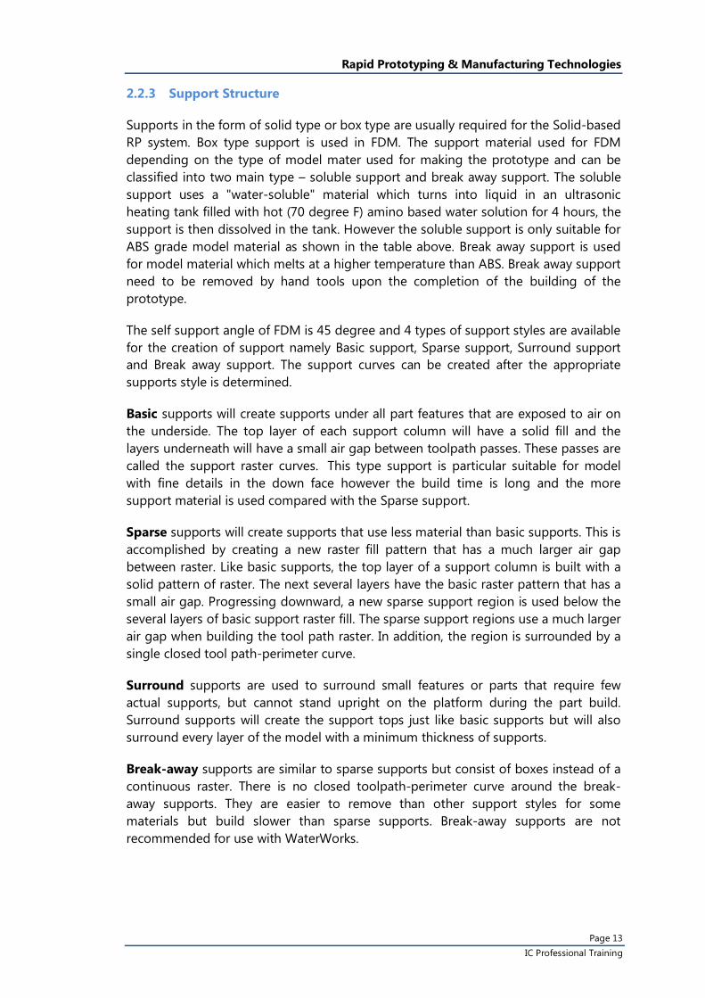
2.3.2 SLS Material (Polymer)
Physical Properties Units PA PA-GF Alumide
Tensile Modulus N/mm² 1700+/- 150 3200 +/- 200 3800+/- 150
Tensile Strength N/mm² 45 +/- 3 48 +/- 3 46 +/- 3
Elongation at Break % 20 +/- 5 6 +/- 3 3.5 +/- 1
Flexural Modulus N/mm² 1240 +/- 130 2100 +/- 150 3000 +/- 150
Charpy – Impact strength kJ/m² 53 +/- 3.8 35 +/- 6 29 +/- 2
Charpy – Notched Impact Strength
kJ/m² 4.8 +/- 0.3 5.4 +/- 0.6 4.6 +/- 0.3
Izod – Impact Strength kJ/m² 32.8 +/- 3.4 21.3 +/- 1.7 NA
Izod - Notched Impact Strength
kJ/m² 4.4 +/- 0.4 4.2 +/- 0.3 NA
Ball Identation Hardness kJ/m² 77.6 +/- 2 98 NA
Shore D-hardness kJ/m² 75 +/- 2 80 +/- 2 76 +/- 2
Heat Deflexion t° °C 86 110 130
Vicat Softening Temperature B/50
°C 163 163 169
Vicat Softening Temperature A/50
°C 181 179 NA
Remark: PA is Polyamine (Nylon), GF is glass fiber reinforcement, Alumide is PA powder mix with aluminum powder; the materials are used in EOS INT P system.

Rapid Prototyping & Manufacturing Technologies
Page 18 IC Professional Training
2.4 Three Dimensional Printing (3DP)
The three Dimensional Printing (3DP) technology was invented at the Massachusetts Institute of Technology and licensed to several corporations. 3DP indeed is the innovation and further evolution of two-dimensional printing technology. The process is similar to the Selective Laser Sintering (SLS) process, but instead of using a laser to sinter the material, an ink-jet printing head deposits a liquid adhesive that binds the material. The following mainly describes 3DP technology which is employed in Z-corp 3D printing.
2.4.1 Process description
The 3D printing process begins with the powder supply being raised by a piston and a leveling roller distributing a thin layer of powder to the top of the build chamber. A multi-channel ink-jet print head then deposits a liquid adhesive to targeted regions of the powder bed. These regions of powder are bonded together by the adhesive and form one layer of the part. The remaining free standing powder supports the part during the build. The processes repeated and solid model is competed and underneath inside the powder bed. Figure 2.10 show a schematic illustration of the 3DP process
Fig. 2.10 Schematic of 3D printing technology
After the part is finished, the loose supporting powder can be brushed away and the removed by vacuum cleaner. Since the “green part” is very fragile, infiltration of glue/ epoxy is needed to be applied on the part surface to improve the strength of part. It should be noticed that any loose supporting powder should be removed completely before performing infiltration to avoid generation of ugly surface.
Input Binder Material
Print Head
Feeding piston

Rapid Prototyping & Manufacturing Technologies
Page 19 IC Professional Training
2.4.2 3DP Material
Material used in Z-corp 3DP include plaster, starch and ceramic powders, plaster powder is commonly used for making concept design model, it is most suitable for concept proofing as the build speed is very fast, typically 2-4 layers per minute. Starch powder is particular used to produce master patterns for investment cast since it can be vaporized in high temperature. Ceramic powder coated with resin is specially designed for making sand casting mould, i.e. Z-cast is a special mixture of sand particle and resin for casting purpose.
Although the build speed of 3DP is relatively fast compared with other RP processes, post-process is time-consuming and laborious. Infiltration is usually performed by manual dipping of glue or epoxy resin. Wax-dipping has being developed and utilized to speed up the post-process but the part strength is much weaker than glue infiltration. A new powder system zp140 has been just developed in which the parts can be cured by dipping into water or spaying on the part surface.
3. Workflow of RP processes
There are basically three stages of building physical RP models based on the CAD data, namely the pre-processing, building and the post processing. Whatever the CAD model is generated by solid modeling or surface modeling approaches, most of RP machine accept only STL file as digital data input in which most commercial Engineering CAD system is capable to convert 3D CAD model into STL format. The STL model is then slice into layers data set and transfer to machine for building model. Completed RP model is then performed corresponding post-processed operations such as cleaning, post-curing and infiltration. Figure 3.1 shows the typical workflows of RP processes
Fig. 3.1 RP processes workflow

Rapid Prototyping & Manufacturing Technologies
Page 20 IC Professional Training
3.1 Pre-processing
The first step in the RP&M process is virtually identical for all of the various systems, and involves the generation of a three-dimensional computer-aided design model of the object. A good, preferably solid CAD modeling or a total enclosed surface – water tight – CAD model is a key component of success RP processing. The CAD file is then translated into a triangulation tessellated STL format, which is the standard of the RP&M field. Figure 3.2 shows a typical example of STL model which is composed of triangles and each triangle is described by a unit normal vector direction and three points representing the vertices of the triangle.
Fig. 3.2 Example of STL model
3.1.1 Verification and fixing of STL file
When one create 3D surface model using common surface modeler, there is very little concern on the orientation of the surface normal, as most of the tool path generation algorithms can detect the material side correctly.
However, when one generate STL data using these surface models, many converters just use the normal data straight from the NURBS surfaces – free form surfaces, thus the STL files generated are not useable without repair.
Triangles in an STL file must all mate with other triangle at the vertex and must be properly oriented to indicate which side of the triangle contains mass. Many STL viewers like Magics RP from Materialise read a STL file to analysis and to correct, the connectivity and gap in the three-dimensional triangle matrix. This process is totally automatic and simple to operate. Figure 3.3 shows a “bad” and “good” STL file.

Rapid Prototyping & Manufacturing Technologies
Page 21 IC Professional Training
Fig. 3.3 “Bad” STL file is fixed “Good” STL file
3.1.2 Part Orientation
Part orientation has a significant effect on the final part quality and prototyping cost. The switching between individual layers takes a significant part of the overall building time and hence must be properly optimized hence to reduce to building time and the building cost. The part should be orientated with minimum height in order to reduce the number of layers.
For processes that need supports structures, part orientation should also be optimized such that it would require minimal support hence reduce to building time and the building material. The ultimate strength of the part will be affected by its orientation within the print box. The part will be strongest along the Y-Axis and the X-Axis and less strong along the Z-Axis which is illustrated in figure 3.4
Fig. 3.4 Effect of orientation to part strength
Hole exists in STL file Hole is filled by “Automatic Fixing”

Rapid Prototyping & Manufacturing Technologies
Page 22 IC Professional Training
Furthermore, staircase effect will be appeared on the near flat curve surface. Hence proper orientation can produce a smooth external curve surface of the prototype. In addition the minimum wall thickness of the part can only be built in some particular orientation.
3.1.3 Support Generation & Editing
The rapid prototyping systems usually bundled with software which allows the automatic creation and editing of the supports. The software will initially generate the supports for all overhang regions based on the default support parameters; figure 3.5 shows the problem of missing support for overhang geometry. After the creation, the support structure can be individually modify, edit, delete or add based on the part geometry. The region by region editing or customization for supports generation has strengthened the essential support and also minimizing the building of unnecessary supports.
Fig. 3.5 Result of missing supports for overhanging areas
Fig. 3.6 SLA Fine-point support
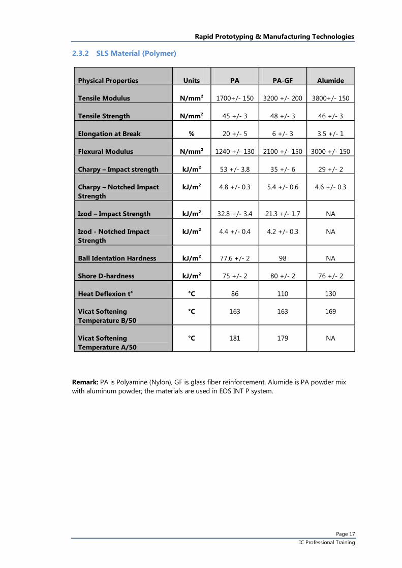
Support can reinforce delicate part while building and in the post processing stage. However over support for delicate part will increase the difficulties of support removal and even destroy the fine details on the down face. Figure 3.7 shows an example of over support.
Down-facing Region
Up-facing Region
Stand
Projection
Desired part or model geometry
Without supports, overhanging areas of part may peel away and damage the whole model
Rapid Prototyping & Manufacturing Technologies
Page 23 IC Professional Training
Fig. 3.7 Over support of SLA part
3.1.4 Slicing (Layer thickness)
A STL model used for RP contains a collection of planar triangular surfaces. These faces define an approximate boundary for the object. Horizontal layers of equal thickness are produced while slicing to produce the outer boundary of the part – slice curve. Then void and solid region of the slice curve can be identified and proper fill pattern can be created for part filling. Typical layer thickness of commonly RP system is ranged from 0.05mm to 0.15mm.
3.1.5 Part Building
The prototype can be built in the RP machine according to the toolpath and control codes generated by the software of the RP system. By laser scanning, disposition, sintering, etc and under limited working envelope with closed control of the processing environment the machine will start the build at the bottom layer. Subsequent layer is added after the completion of the previous layer until the final layer was build. Hence, RP process also refers to layer manufacturing.
3.1.6 Post processing
Once the last layer on the part has been built, the prototype need to have undergo some post processing processes such as removal of support, cleaning, depowder, drain excessive resin, post curing in SLA, infiltration of resin/wax, etc. The post processing is aimed to clean and reinforce the green part.
Additional surface finish procedures such as sanding, sand blasting, painting or even electroplating are normally employed for cosmetic prototypes.

Rapid Prototyping & Manufacturing Technologies
Page 24 IC Professional Training
4. Rapid Tool Production
Only when the production quantity is massive that the expensive tooling cost can be justified. As a result, the way of how to produce tooling quicker and more economically especially for small batch manufacturing becomes a big concern. Furthermore, in the product design and development process, there is always in need of some intermediate tooling to produce samples for marketing, functional test, or production process planning and evaluation purposes. In this respect, RT is the ideal mean to fit the needs.
Rapid Tooling (RT) is the result of combining Rapid Prototyping techniques with conventional tooling practices to produce small quantity of plastic or metal components from electronic CAD data directly or indirectly. Direct RT technology such as Direct Metal Laser Sintering (DMLS) which fabricate production tooling from CAD data whereas Room Temperature Vulcanization (RTV) silicone rubber mould is the most commonly used indirect approach for plastic components duplication.
4.1 Type of RT Processes
Low volume (from 10 to 100)
• RTV Soft Tooling
Intermediate volume (from 100 to 1000)
• Metal filled Epoxy Tooling • Direct Metal Laser Sintering
4.2 RTV Soft Tooling
RTV silicone rubber mould is one of the important kinds of soft tooling which is an effective, high fidelity and inexpensive way to create multiple copies of a master prototype part. Indeed, this technology has been used by the industry for many years. The only thing new is that the master pattern is produced by the RP technology. The other common kind of soft tooling material is tooling grade Polyurethane.
This technology is not specially designed for a particular RP process. In fact, master patterns produced from most RP processes are suitable to apply for this technology.
RTV molds can faithfully duplicate details and textures present on the master pattern. Apart from detail, geometry can also be fully duplicated from the master part when prototypes are removed from the mould. Great care should be taken to ensure that the pattern is in perfect condition. After RTV mould is completed, it can be used to further produce limited quantity of prototypes with a wide variety of material properties.

Rapid Prototyping & Manufacturing Technologies
Page 25 IC Professional Training
Its application is mainly to produce plastics or metal prototypes in small batch by vacuum assisted casting or gravity casting method. The casting materials normally used are PU, polyester, epoxy, tin-lead alloy (200 °C), pewter (230 °C) and zinc alloy (400 °C).
The batch size is from several pieces to hundreds. Multiple moulds, sometimes, are required depend on the complexity of the parts. In fact, the ease of producing multiple moulds is one of the advantages of this technology. However, the process is tedious and required high skill workers attendance.
4.2.1 Process Description
One-piece mould approach
This process begins with a master pattern which normally output from RP system directly. It requires to sand and polish the part surface well since the RTV mould will reproduce any and all surface defects on the master pattern, and in turn will transfer them onto the final model. Then, the pattern attached with gating system is mounted in a mould box. Silicone rubber is mixed with specific amount of hardener and poured into the mould box. Degassing in vacuum chamber is preferred to avoid trapped air caused by mixing and pouring. After solidification, the mould is then spitted into mould halves according to the predetermined parting lines. Figure 4.1 shows the RTV mould making process of one piece mould approach.
Fig. 4.1 Processes of making RTV mould (one-piece mould approach)
Rapid Prototyping & Manufacturing Technologies
Page 26 IC Professional Training
Two-pieces mould approach
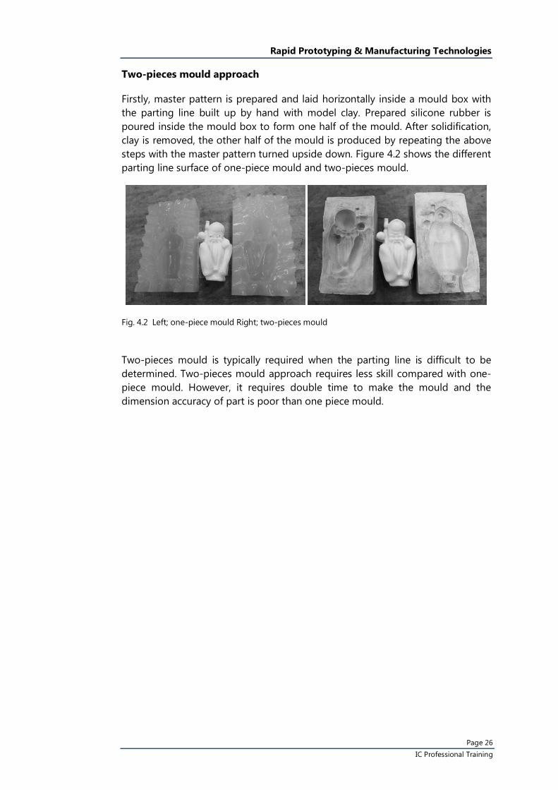
Firstly, master pattern is prepared and laid horizontally inside a mould box with the parting line built up by hand with model clay. Prepared silicone rubber is poured inside the mould box to form one half of the mould. After solidification, clay is removed, the other half of the mould is produced by repeating the above steps with the master pattern turned upside down. Figure 4.2 shows the different parting line surface of one-piece mould and two-pieces mould.
Fig. 4.2 Left; one-piece mould Right; two-pieces mould
Two-pieces mould is typically required when the parting line is difficult to be determined. Two-pieces mould approach requires less skill compared with one-piece mould. However, it requires double time to make the mould and the dimension accuracy of part is poor than one piece mould.

Rapid Prototyping & Manufacturing Technologies
Page 27 IC Professional Training
4.2.2 Type of RTV Silicone Rubber
RTV silicone rubber can be divided into two types; condensation and addition types, the following table shows the differences among them.
Condensation Type Addition Type
Features • Lower costs • Broader product range • Less sensitive to exact mix
ratio • Accelerator catalysts
available to speed up cure
• Mixing of grades possible to achieve desired hardness
• Low shrinkage, below 0.1%
• Marginally higher tensile strength
• Slightly tougher rubber
• Need for careful and accurate mixing
• Good abrasion resistance
• Can be accelerated using heat
• Tolerant to the addition of silicone fluid as a softener
Shrinkage Slightly higher than the addition type
Low
When Temperature Increase
Curing Time decreases
(5oC----7hrs;
25oC-----5hrs;
50oC-----4hrs(max temp))
Curing Time decreases
(50oC-----2hrs;
100oC-----30min;
150oC-----10min;)
When Humidity Increase
Curing Time decreases Curing Time decreases
When Quantity of Curing Agent Increase
Curing Time decreases but there are limits
Curing speed will not be altered but will adversely affect the physical properties.
*Quantity of curing agent must be carried out as accurately as possible.
Curing Impediments
No Yes
Remarks By product will come out. Dimensions of mould will be slightly affected. (about 0.5%)
Warm the rubber mold to the curing temperature before pouring resin into a thermally cured the rubber mold to raise dimensional accuracy.

Rapid Prototyping & Manufacturing Technologies
Page 28 IC Professional Training
Mixing Ratio is a term used to state the amount of each material to be mixed in a multi-component material. The mixing ratios for two-part RTV products are described on the individual product data sheets and are given as a ratio by weight of each material.
Pot life is the length of time that a catalyzed resin system retains a viscosity low enough to be used in processing. This is also known as WORKING LIFE or USABLE LIFE.
Curing condition is the condition which can provide the optimum properties for a silicone rubber. This typically depends on time and temperature.
4.2.3 Considerations of making RTV mould
To duplicate a good product by soft tooling, planning is very important as the part may be blocked inside the mould if the parting surface is not well defined. All holes should be filled by tapes to separate individual mould half before pouring of silicone rubber.
For master pattern with flat surface, the parting surface should be located on the flat surface and use plastic type as a marking. For master pattern with free-form geometry, parting line should be located on the position which gives lowest effect to the appearance.
It is important to evaluate the pattern if there are any undercuts that would lock the casting in the mold. Small undercuts can be ignored since the silicone rubber is flexible material. To deal with some deep holes feature such as boss, metal inserts can be used to replace the silicon material by attaching the inserts to the part before pouring of moulding material. 4.3 PU Casting
Even RTV mould can be used for different material, PU is the most popular material accompany with RTV mould for producing plastic components. There are two different approaches for PU casting, Top-down approach (direct gate) and Bottom-up approach (by gravity).
For Top-down approach, PU is poured into the mould directly through a gate connected on top of the part. Firstly, weighted material and RTV mould are put into a vacuum chamber for degassing. PU resins are mixed together inside a vacuum chamber, it is then poured into the mould via a funnel and air is reintroduced simultaneously to force the PU material into the mould. This method is suitable for casting small components such as jewelry that has fine detail. Figure 4.3 shows the processes of PU casing by this top-down approach.

Rapid Prototyping & Manufacturing Technologies
Page 29 IC Professional Training
Fig. 4.3 Steps of PU casting
For Bottom-up approach, PU material is poured into the RTV mould and filled into the moulding cavity by gravity. Vent channels are need to be added at the top areas of part to allow air out. This method is most suitable for large casting part in which the mould is unable to put inside a vacuum chamber. Figure 4.4 shows the different set up of top-down and bottom-up approaches
Fig. 4.4 Left; top-down approach Right; bottom-up approach
RTV Mould
Cavity
Vent channels Material input Material input

Rapid Prototyping & Manufacturing Technologies
Page 30 IC Professional Training
4.4 Epoxy Tooling
Epoxy tools are used to manufacture parts or limited runs of production parts. Expoxy tools are used for:
• Plastics injection prototype Mould • Mould patterns for casting • Vacuum forming moulds • Sheet metal forming moulds • Reaction injection moulds
Mould that is made of plastics is built from casting some special grade epoxy resins directly onto the RP master model. This mould making method does not require high precision machine tools as with conventional metal mould production. This technology of direct transversal from the master model allows large reduction in mould production costs and time.
In the past, plastics materials are not suitable for injection mould due to the lack of strength and the high shrinkage during curing. Many problems arise such as damage during mould making and moulding process. However, a special grade epoxy resin is developed for better strength and stiffness. Epoxy resin is a thermoset plastic reinforced with composite materials that can be cast to shape before cured. This special grade epoxy resin is aluminum powder filled for strength, stiffness and thermal conductivity improvement.
The mould made by this process is only suitable for injection moulding of plastics parts. Common plastics materials like ABS, POM, etc. can be produced from this mould in small batch size up to 3,000 pieces.
4.4.1 Process Description
The process of producing epoxy tooling is somehow similar as making RTV two-piece mould but usually double duplication techniques is used. A RP master pattern is sanded and polished and the parting line is formulated by clay. A thin layer of mould release agent is applied on the surface of the master pattern, RTV is then poured into the mould box. The RTV is used as the negative mould master patterns for casting of metal epoxy in forming the mould cavity and mould core. As the density and viscosity of epoxy resin is relativity high, degassing is carried out by several times in order to extract out all of the trapped gases. After pre-curing, the master pattern is removed and the mould halves are put into oven step by step increasing the temperature to 280℃ for post thermal curing.
The mould halves are then turned to CNC machine for producing the sprue, runner, gate and ejecting system. The mould is completed and ready for plastic injection.

Rapid Prototyping & Manufacturing Technologies
Page 31 IC Professional Training
4.5 Direct Metal Laser Sintering (DMLS)
Direct Metal laser Sintering (DMLS) builds solid metal parts directly from powdered metals. It always used to build simple rapid tooling because of short lead times, eliminate the cavity machining required. For advanced, cooling channels and inserts can also be built in the rapid tools. Rapid tools using harder, tougher materials can be used to inject hundreds to thousands of plastic parts.
Fig. 4.5 Example of DMLS insert for injection moulding

Rapid Prototyping & Manufacturing Technologies
Page 32 IC Professional Training
References
• Wohlers, Terry T. (1999), Rapid prototyping & tooling, state of the industry : 1998 worldwide progress report, Fort Collins, Colo. : Wohlers Associates, Inc.
• Friedrich B. Prinz (1997), JTEC/WTEC panel on rapid prototyping in Europe and Japan : final report, Baltimore, Md.: Rapid Prototyping Association of the Society of Manufacturing Engineers
• Lamnont Wood (1993), Rapid Automated Systems: An Introduction, New York: Industrial Press
• Dearborn, Mich. (1994), Rapid prototyping systems : fast track to product realization : a compilation of papers from Rapid Prototyping and Manufacturing '93, Society of Manufacturing Engineers in cooperation with Rapid Prototyping Association of SME
• Chua Chee Kai, Leong Kah Fai. (1997), Rapid prototyping : principles & applictions in manufacturing, New York : John Wiley & Sons
• Marshall Burns (1993), Automated fabrication : improving productivity in manufacturing, Englewood Cliffs, N.J. : PTR Prenrice Hall
• Jerome L. Johnson (1994), Principles of Computer Automated Fabrication, Irvine, Calif. : Palatino Press, c1994
• D. Kochan (1993), Solid Freeform Manufacturing - Advanced Rapid Manufacturing, Amsterdam ; New York : Elsevier (Request)
• Joseph J. Beaman (1997), Solid freeform fabrication : a new direction in manufacturing : with research and applications in thermal laser processing, Dordrecht ; Boston : Kluwer Academic Publishers(Request)
• øyvind Bjørke (1996), Layer manufacturing : a tool for reduction of product lead time, Trondheim, Norway : Tapir Publishers
• Graham Bennett (1996), Second National Conference on Developments in Rapid Prototyping and Tooling, Bury St. Edmunds : Mechanical Engineering Publications
• Preston G. Smith, Donald G. Reinertsen (1991), Developing products in half the time, New York : Van Nostrand Reinhold
Bibliography
http://www.custompartnet.com/
Rapid Prototyping Journal, Bradford, West Yorkshire, England Birmingham, AL: MCB University Press Ltd.
Prototyping Technology International, Surrey : UK & International Press
Time-compression technologies. Europe, Tattenhall [England] : Rapid News Pub
The rapid prototyping directory, San Diego, Calif. : CAD/CAM Pub