Rapid prototyping: Creating a minimum viable product using ...
49
Rapid prototyping: Creating a minimum viable product using a single-board microcontroller Oscar Storbacka Degree Thesis Plastteknik 2018
Transcript of Rapid prototyping: Creating a minimum viable product using ...
Rapid prototyping: Creating a minimum viable
product using a single-board microcontroller
Oscar Storbacka
Degree Thesis
Plastteknik
2018

DEGREE THESIS
Arcada
Degree Programme: Plastteknik
Identification number:
Author: Oscar Storbacka
Title: Rapid prototyping: Creating a minimum viable product
using a single-board microcontroller
Supervisor (Arcada): Mirja Andersson
Commissioned by:
Abstract:
This thesis explores the minimum viable product development technique, most often used
in software development, as an alternative product development technique when making a
physical product. A literature review is done on additive manufacturing, minimum viable
product and single-board microcontrollers.
As an experiment a simple concept is developed, and a market validation is performed. A
prototype is made from that concept and then iterated upon and the iteration process is
documented. The result is a functional minimum viable product which then can be the basis
for further studies.
The results of the experiment are evaluated, and issues with it are brought forward. Further
research is theorized, including how the product journey continues from the prototype stage
to production prototyping, and how the product journey was for successful companies and
companies that failed in being sustainable. Four new key principles are introduced, derived
from the literature and experiments, as guidelines to create more sustainable development
and a more streamlined development process.
Keywords: Additive manufacturing, rapid prototyping, minimum viable
product, single-board microcontroller, Arduino, product
development,
Number of pages:
Language: English
Date of acceptance:
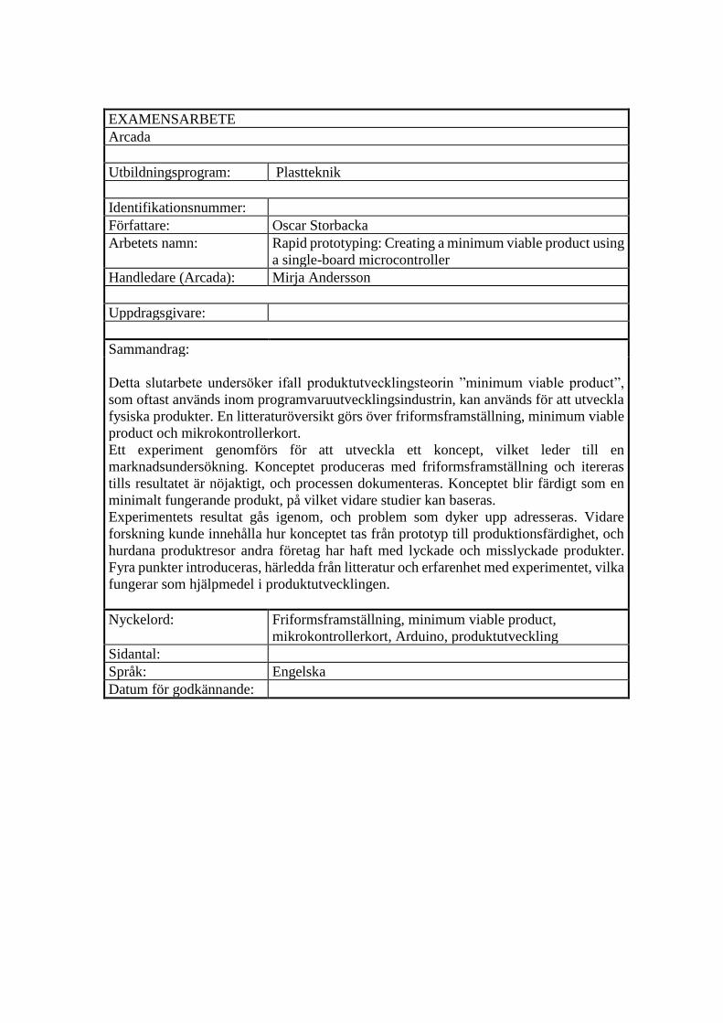
EXAMENSARBETE
Arcada
Utbildningsprogram: Plastteknik
Identifikationsnummer:
Författare: Oscar Storbacka
Arbetets namn: Rapid prototyping: Creating a minimum viable product using
a single-board microcontroller
Handledare (Arcada): Mirja Andersson
Uppdragsgivare:
Sammandrag:
Detta slutarbete undersöker ifall produktutvecklingsteorin ”minimum viable product”,
som oftast används inom programvaruutvecklingsindustrin, kan används för att utveckla
fysiska produkter. En litteraturöversikt görs över friformsframställning, minimum viable
product och mikrokontrollerkort.
Ett experiment genomförs för att utveckla ett koncept, vilket leder till en
marknadsundersökning. Konceptet produceras med friformsframställning och itereras
tills resultatet är nöjaktigt, och processen dokumenteras. Konceptet blir färdigt som en
minimalt fungerande produkt, på vilket vidare studier kan baseras.
Experimentets resultat gås igenom, och problem som dyker upp adresseras. Vidare
forskning kunde innehålla hur konceptet tas från prototyp till produktionsfärdighet, och
hurdana produktresor andra företag har haft med lyckade och misslyckade produkter.
Fyra punkter introduceras, härledda från litteratur och erfarenhet med experimentet, vilka
fungerar som hjälpmedel i produktutvecklingen.
Nyckelord: Friformsframställning, minimum viable product,
mikrokontrollerkort, Arduino, produktutveckling
Sidantal:
Språk: Engelska
Datum för godkännande:

TABLE OF CONTENTS
1 INTRODUCTION ........................................................................................................... 1
2 LITERATURE REVIEW .................................................................................................... 3
2.1 ADDITIVE MANUFACTURING ............................................................................................... 3
2.1.1 Stereolithography .................................................................................................... 4
2.1.2 Selective laser sintering ........................................................................................... 6
2.1.3 Fused deposit modeling ........................................................................................... 7
2.2 MINIMUM VIABLE PRODUCT ............................................................................................... 8
2.2.1 MVP and hardware ................................................................................................ 10
2.3 SINGLE-BOARD MICROCONTROLLERS .................................................................................. 11
2.3.1 Arduino project ...................................................................................................... 13
2.3.2 LightBlue Bean ....................................................................................................... 13
3 METHOD ................................................................................................................... 15
3.1 PROOF OF CONCEPT ........................................................................................................ 15
3.1.1 Market validation .................................................................................................. 16
3.2 DESIGNING THE PRODUCT ................................................................................................ 18
3.2.1 Designing the circuit .............................................................................................. 18
3.2.2 Designing the case ................................................................................................. 21
3.2.3 Designing the software .......................................................................................... 23
3.3 ITERATION PROCESS ........................................................................................................ 24
3.3.1 Circuit ..................................................................................................................... 25
3.3.2 Case ....................................................................................................................... 25
3.3.3 Software ................................................................................................................ 27
3.4 PRODUCTION ................................................................................................................. 27
4 RESULTS .................................................................................................................... 29
5 DISCUSSION .............................................................................................................. 31
6 CONCLUSIONS ........................................................................................................... 32
7 ABSTRAKT ................................................................................................................. 35
8 REFERENCES .............................................................................................................. 38

FIGURES
FIGURE 1: STEREOLITHOGRAPHY DIAGRAM [5] ........................................................................................................ 5
FIGURE 2: SELECTIVE LASER SINTERING DIAGRAM [14] .............................................................................................. 6
FIGURE 3: FUSED DEPOSIT MODELING DIAGRAM [20] ............................................................................................... 7
FIGURE 4: THE ITERATION CIRCLE IN MVP .............................................................................................................. 9
FIGURE 5: ATMEGA328 MICROCONTROLLER [34]................................................................................................ 12
FIGURE 6: ARDUINO UNO [36] .......................................................................................................................... 13
FIGURE 7: A RENDER OF THE LIGHTBLUE BEAN, WITH PINS WRITTEN OUT. THE LARGE BLUE BLOCK IS THE BLUETOOTH CHIP
AND THE BLACK BLOCK UNDERNEATH IS THE MICROCONTROLLER. [42] .............................................................. 14
FIGURE 8: THE BASIC CONCEPT OF THE BLUETOOTH CONTROLLER REMOTE SHUTTER. A DATA PACKET IS SENT FROM THE
MOBILE DEVICE TO THE MICROCONTROLLER, WHICH THEN SHORTS THE TWO WIRES TO TRIGGER THE CAMERA SHUTTER
.......................................................................................................................................................... 16
FIGURE 9: SWOT ANALYSIS FOR THE PRODUCT ..................................................................................................... 17
FIGURE 10: OPTOCOUPLER CIRCUIT DIAGRAM [45]................................................................................................ 18
FIGURE 11: 10-PIN CONNECTOR LAYOUT FOR NIKON CAMERAS, WITH A DIAGRAM OF THE BASIS FOR REMOTE TRIGGERING AND
VOLTAGE READINGS AND PURPOSE OF THE PINS [46] ..................................................................................... 19
FIGURE 12: CIRCUIT DIAGRAM, DIGITAL OUT 0 AND 1 (D0 AND D1 RESPECTIVELY) PROVIDES CURRENT FROM THE LIGHTBLUE
BEAN, TRIGGERS THE OPTOCOUPLERS, WHICH IN TURN THEN LETS THE CURRENT FLOW FOR THE FOCUS AND SHUTTER TO
TRIGGER ............................................................................................................................................... 20
FIGURE 13: USING A BREADBOARD AND AN ARDUINO MICROCONTROLLER TO DESIGN THE CIRCUITRY. ............................. 21
FIGURE 14: THE CASE, WITH THE LIGHTBLUE BEAN INSIDE OF IT, EXPLODED IN THE ASSEMBLY VIEW INSIDE SOLIDWORKS. ... 23
FIGURE 15: THE CIRCUIT SOLDERED ON TO THE LBB, A 2-EURO COIN FOR SCALE .......................................................... 25
FIGURE 16: THE THREE ITERATIONS OF THE UPPER PART OF THE CASE THAT CHANGED THE MOST ..................................... 26
FIGURE 17: FIRST ITERATION OF THE CASE DESIGN, STRAIGHT FROM THE PRINTER WITH NO POST-PROCESSING DONE .......... 26
FIGURE 18: THE CASE IN SOLIDWORKS ................................................................................................................ 27
FIGURE 19: THE FINAL PRODUCT, OPENED. BOTTOM PART IS ON THE LEFT AND TOP PART ON THE RIGHT ........................... 28
FIGURE 20: THE FINALIZED PRODUCT, SEATED IN THE HOT SHOE ON A CAMERA. THE CABLE GOES FROM THE PRODUCT TO THE
CAMERA REMOTE SOCKET ........................................................................................................................ 29
TABLES TABLE 1: TABLE OF REQUIREMENTS AS STATED IN THE DESIGNING PHASE AND THE RESULTS OF PRODUCTION ..................... 30
1
1 INTRODUCTION
“Hardware is hard” is a cliché within the startup communities, repeated as often as new
hardware companies go under, but as old clichés go, they are usually based on some
truths. The working capital of creating a physical product is so much larger than writing
software or offering services, because of the costs involved in mass producing anything,
and the obligatory steps needed before even getting to the mass production phase, which
already puts hardware in a tougher spot. Even with new services provided for companies
to promote and judge the demand for their products, services like Kickstarter and
Indiegogo, a lot of entrepreneurs have tried to solve the startup hardware problem, but on
multiple occasions have they acquired numerous pre-orders and gained much publicity
only to suddenly fall short of their intended target. And even if the company manages to
get angel investors to invest in the product, the statistics are still grim; Up to 70% of
companies that receive investments fall through [1].
The increase of network-connected devices and the general trend of Internet of Things
creates the demand for companies that try to solve the issue of prototyping complex
circuitry and networking. Instead of manually assembling circuit boards in a garage, these
companies sell small single-board microcontrollers that include modern communications
technologies that allow for quickly going from idea to product, without needing to have
premade contacts at manufacturers [2]. This insurgency of easy-to-learn microcontrollers
and the rapid success of 3D printing is creating a much quicker iteration process than ever
before.
The purpose of this thesis is to examine the product development technique, minimum
viable product, and research if it can be applied to physical products. The thesis tries to
answer three main research questions on this topic:
RQ1: Can the product development technique “minimum viable product” be used for
hardware projects in the same manner as it is used for software projects?
RQ2: What are the available tools for making a small hardware project?
RQ3: How do you iterate on hardware?
The interest of additive manufacturing has improved as of late which makes it the natural
selection for the manufacturing method of this thesis. Single-board microcontrollers have

2
created a market segment where the point of entry into making an electronics-based
product is so much easier than any other option that it is chosen for this thesis.
As such, in the literature review the state of additive manufacturing is reviewed, and three
main methods are focused upon. The minimum viable product development technique is
inspected from a general view, as written by its inventors and as used in the software
industry, then separately from a hardware view which is more experimental. Single-board
microcontrollers are reviewed, and a single microcontroller family is selected as the main
focus point.
As a proof of concept, a concept of product is made and iterated upon until a working
prototype is complete, and the next steps are considered. Since the creation of a product
is such a vast effort, the scope of the proof of concept has to be well defined and limited,
to create a safe space for experimentation and iteration to occur, without too much thought
on viability in the long run. As such the development is stopped as soon as the product is
usable in its simplest state.
The process of creating a prototype and a product is then discussed and further research
is suggested. Four principles are introduced for developing products to improve success
rate.

3
2 LITERATURE REVIEW
This section contains the literature review for additive manufacturing, minimum viable
product, and single-board microcontrollers. Additive manufacturing is a very broad area,
with a lot of different production methods available, and in order to limit the scope of this
literature review only three main methods are covered in detail, and as limitations to
access to particular technologies will force the method to work around fused deposit
modelling, interest lies in covering that particular method in even finer detail.
Furthermore, there are also equally many different single-board microcontrollers, but
since the LightBlue Bean, which offers Bluetooth connectivity and a set of features that
are appropriate, will be used in this project, this review will focus on the Arduino family
(which the Bean is based on) and the LightBlue Bean.
2.1 Additive manufacturing
In their core principles, most additive manufacturing (known also as rapid prototyping or
even more familiar for consumers as 3D printing) methods mostly work in the same way.
In order to create a three-dimensional piece, a computer program slices the 3D-model into
layers, which then can be fed into the driver for the printer. The driver then creates the G-
code for the path the printer will take to print each layer on top of each other, and the
piece is printed. But as simple as it sounds, each method offers different solutions for the
common issues met when printing. [3]
The first issue is how accurately the method can reproduce the model in real life. Even
though these pieces usually are made for prototyping purposes, where standards are a
little looser, the accuracy of the printer still limits the detail that can be reproduced. If the
piece is small or relies on some very thin or small features, it might be hard to produce it
with a 3D printer. [4]
The second issue is how fast it will manufacture the piece. The speed of which you can
make a prototype might limit the rate you can develop products. This is usually also a
trade-off between the first issue and this one. Faster printing usually will lead to worse
results, while going slower might increase the accuracy the printer will achieve. [5]
Lastly, if a piece has a difficult geometry or has overhanging parts. This also touches on
the first issue, but in a different way. If you are trying to create a lip for a product, you
cannot just lay a layer of material on thin air, instead, you need to either rotate the piece

4
so that the geometry is supported by something or add temporary supporting structures to
the part you are printing. Modern software will add these structures for you, but they
might add printing time, and blemishes to the printed piece. These blemishes can, of
course, most of the time be removed in a post-processing process using either a physical
or chemical removal of material, but this adds to the time needed to get the finished piece
ready for testing. This process can become hard to understand without experiencing them
first hand, as when modeling an object in a computer program, there are no gravity or
weight, so any shape is possible, but when that object is then made in the real world,
unexpected errors may happen if no design considerations are made. [5]
2.1.1 Stereolithography
Stereolithography (SLA) is an additive manufacturing method patented in 1984 [6] and
was the first modern 3D printing method developed [7]. It is designed to use UV-light to
cure layers of a liquid resin on top of each other creating a three-dimensional piece. SLA
was a response to a multi-beam system wherein the resin was cured in three-dimensions
within the resin but was lacking in accuracy and exposure control and created complex
control situations when the focus spot was deeper in the liquid resulting in less than
desirable results [6].
The material used in an SLA apparatus is an ultraviolet (UV) curable resin (also known
as photopolymers), which is then is exposed to a UV-beam, which cures the resin in a
layer. The layer is then either lowered or is raised, depending on the machine and the
process. The right side up method is usually used in larger scale industrial machines,
which require more maintenance, has larger resin baths and can print larger objects, and
introduces less stress on the object as it is sunk into the resin as the layers progress. The
alternative is then the inverted method where the resin bath is only a fraction of the right
side up method, and the resin then cures on a nonstick surface on the bottom of the resin
bath and is then separated and lifted out of the bath. This will produce more stress on the
part as it is lifted in the air but requires much less maintenance and initial resin and such
is more suited for the consumer, but the object size limitations are much smaller than the
right side up method. [8] The use of photopolymers means that there are limited amounts
of variations in the material compared to other manufacturing methods, and due to the
nature of the curing of the resin, the resulting pieces also inclined to become brittle in

5
sunlight and UV exposure [9]. During the curing process for the layer, the polymerization
reaction is not completed, which results in that the printed part is isotropic, meaning that
the layers also form covalent bonds with the next layer, giving the piece uniform
mechanical properties, independent of the direction of the force, and also a cleaner visual
with a lack of visible printing lines [8].
When designing the object, and planning for manufacturing using SLA, the inverted
printing process’ separation stage produces high amounts of stress on the object, so large
Z-axis cross-sectional areas will be under considerable stress. In order to reduce this issue,
the piece can then be rotated at an angle, minimizing the stresses. This then produces the
need for additional supports to hold the object at the correct position, so careful
consideration has to be taken when deciding if SLA is the optimal method. The accuracy
of an SLA print can go beyond what the Fused Deposit Modelling method is capable of,
with SLA achieving an accuracy between 25 and 200 microns. [10]
Stereolithography was the first commercially available rapid prototype method, released
to the public in 1988, by 3D Systems, Inc [11], and they have continued to produce and
develop different 3D printing systems for industry and consumers.
Figure 1: Stereolithography diagram [5]
6
2.1.2 Selective laser sintering
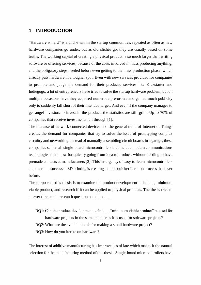
Sintering, as defined by the Encyclopaedia Britannica: “the welding together of small
particles […] by applying heat below the melting point” [12]. The method was developed
at around the same time as SLA, and selective laser sintering (SLS) functions in a similar
manner. Instead of a basin of liquid resin, the material used is in a pulverized form. The
powder is sintered according to the layer using a high-powered laser, whereafter, the
platform is lowered, and another thin layer of powder is spread over the platform, and the
next layer can be sintered. This has the significant advantage that no support structures
are needed for overhanging parts or similar problematic geometry since the surrounding
powder will support the full structure at all times. Sintering also allows for a wider range
of materials, including metals and ceramics. The remaining powder after the pieces is
finished can also be reused, so although the initial material usage is high, most of it will
be used in the end. [13]
Figure 2: Selective laser sintering diagram [14]
The downside of SLS is that you cannot print fully enclosed but hollow parts, since the
powder will then be trapped inside the part, thus a drain hole is always needed. Another
issue for affordable printers for the public is that the heating and melting of the powder
must be accurate up to 2 degrees Celsius which is hard in non-commercial settings [15].
7
The high temperatures needed to sinter the object also may contribute to some warping
of the piece, especially for large flat surfaces, and most pieces experience a shrinkage
which must be taken into consideration before starting the print [16]. The surface finish
is also very porous and rough when printed and requires more post-processing than other
methods if the piece is to be as smooth as a similar part printed using SLA [17].
2.1.3 Fused deposit modeling
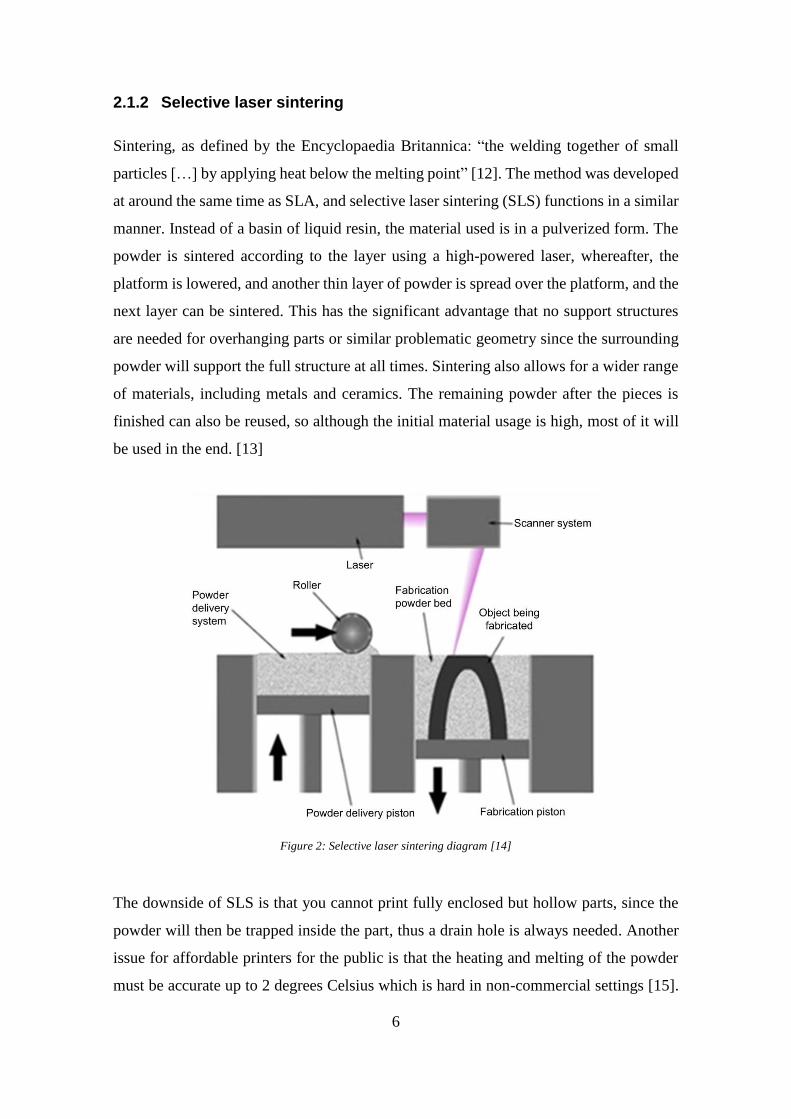
(FDM) is the most popular rapid prototyping method currently on the market [18]. The
term FDM was coined by Stratasys, Inc. in 1989 [19] and the company has also produced
FDM printers to the market since then.
Figure 3: Fused deposit modeling diagram [20]
Unlike SLA and SLS, fused deposit modeling works by extrusion. A filament wire of
thermoplastic is lead through a liquefier, usually by means of a roller controlled by a
stepper motor, which then pushes the material out of a small nozzle, fitted on a head
which can move in 3 directions. Once the material is out of the nozzle it will cool rapidly,
since the build platform the liquid material is pushed on is of much lower temperature.
This way, the machine can lay out a layer of material on top of the platform and rapidly
lay the next layer on top. The simplicity of the system has pushed its popularity to the
consumer markets, and various open-sourced versions of this system are available to build
online [21]. Since there are no liquid baths or powders that need to be applied the FDM
requires a very minimal amount of mechanical properties, and most of the difficulties lie
in the X-Y-Z coordination and accuracy of the nozzle [4].
As the matter is extruded out of a nozzle, some geometry is especially disadvantageous,
and the solutions to those are often not as elegant. If there is a gap between two points
8
and a bridge connecting the two points, the lower layer will not hold up itself and will
start to sag. Rotating the part might fix the issue or splitting the part into two and gluing
the two parts together in post-processing, but some designs make the gap inevitable. The
other options include making the gap smaller to lower the risk of the sagging occurring,
but the only way to be sure is to use supports, which then can leave hefty marks on the
finished surface, or even potentially damage the surface. [22]
Another issue is that as the nozzle extrudes material, it also slightly forces it onto the
lower layer, which causes the layer to be compressed into a more oval shape. This is
especially notable on the foot of the part, where it might create a flare out from the part,
and also in vertical holes, which are then undersized per the original design, as the
diameter of the extrusion exceeds the expected diameter. The issue of adhesion also is
visible in overhangs, where the limit is around 45 degrees, as above it less than 50% of
the material will be supported by the layer underneath, and the quality loss and the thin
lip then deform from the heat applied to the material. [22]
The accuracy of FDM suffers from the fact that it cannot be more accurate than the bead
of extruded material that comes out of the nozzle. The bead also limits the corners of the
print to be rounded and can never be perfectly square. Warping occurs as well, again on
large flat surfaces. Compared to SLA the finished piece also won’t be isotropic, but
anisotropic, meaning that the direction of the force and the way the piece is layered will
affect its mechanical strength.
2.2 Minimum viable product
Minimum viable product (MVP) is a product development technique most often used in
software development, which was first introduced by Frank Robinson in 2001 [23]. The
concept is that instead of creating a full-fledged product, you create something that is
working but not finished and then sell that to fund the rest of the development [24]. It is
a rapid development technique that results in a much quicker feedback loop with the
customers and an easier start to the product development. The term minimum is not a set
amount in this case, but more a guideline to judge. It refers to the next word, viable, in
the sense that something has to be viable in order to sell, one could even think of viable
and sellable being interchangeable. The translation of the term then becomes: The
9
minimum amount of work needed to create a product that someone else would want to
buy.
Eric Ries calls the early adapters for “visionaries” [24], in which that they see the product
not as it is in its early stage but what it could become. These visionaries are more likely
to accept a subpar product and more willing to give feedback to the developers that can
then be used to improve the product. The selling point behind MVP is that the iteration
and feedback from the visionaries can help to avoid building something that the customers
do not want, and minimizes time spent on something that will not sell [25]. The product
thus creates some sort of value to its customers adding meaning and targets to develop
for. Ries calls this the value hypothesis, which Münch et al. [26] explains as:
In Lean Startup terminology, a value hypothesis and a minimum viable product (MVP) need to be
developed. Following Ries, a value hypothesis “tests whether a product or service really delivers value
to customers once they are using it”. An example of a value hypothesis is that customers of a specific
customer segment will choose to sign up for a service based on a given set of features being offered.
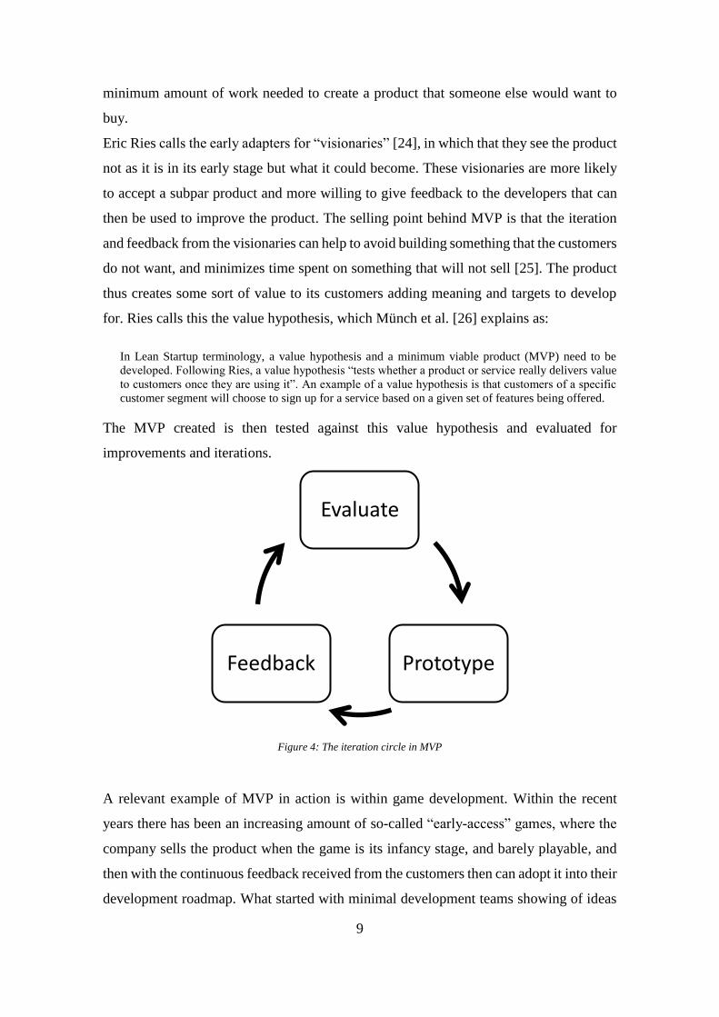
The MVP created is then tested against this value hypothesis and evaluated for
improvements and iterations.
Figure 4: The iteration circle in MVP
A relevant example of MVP in action is within game development. Within the recent
years there has been an increasing amount of so-called “early-access” games, where the
company sells the product when the game is its infancy stage, and barely playable, and
then with the continuous feedback received from the customers then can adopt it into their
development roadmap. What started with minimal development teams showing of ideas
Evaluate
PrototypeFeedback

10
and asking for small, under five euro, payments have then transitioned to larger teams
with bigger visions selling products for over thirty euros. People are more than willing to
be the visionaries for these games and prove a loyal fan base as well. [27] [28]
A commonly used technique for testing a value hypothesis is to do A/B testing [24]; In
which you have two different designs or theories, and by implementing both and testing
them against each other, you gain valuable knowledge about what the customers want
and how they react to each hypothesis.
An example where it is commonly used is with web applications. It is easy to create two
separate calls for action, with different colored buttons and then randomly present each
of the versions to users. You can then gather data on which button then generates more
clicks and affirmative actions on the site. [29]
2.2.1 MVP and hardware
The Cambridge dictionary defines hardware as “the physical and electronic parts of a
computer, rather than the instructions it follows” [30]. Applying then the previous points
to hardware product development requires rethinking. The fluid nature of software
development does not translate to the engineering and production it takes to create
something physical. The delays from the engineering department to factory can extend
over days and prototyping often requires manual labor, and any mistakes made in the
shipped product cannot be patched at the destination of the product, resulting in that
companies have to be more careful in shipping. The production also requires much more
capital for each production run than any software release, so the barrier to entry is already
very high.
Marc Barros states that “The key to a great hardware MVP is focusing on a single feature
[…] and getting to market quickly” [31]. Focusing on one single feature that defines the
product creates a solid base to refine on, and to expand upon when needed. Barros argues
that the most refined products today start as something simple and focused and has
evolved into the well-executed and stylish product over time.
A/B testing within hardware is not as easy as with software. You cannot present a random
design to a user of your product since they buy that specific product. Therefore, you must
introduce all the testing in the prototype stage and try out fewer designs, and with fewer
11
customers, which might introduce some uncertainties in the design. Thus, focusing on
one singular feature might then create an easier focus in the prototyping phase.
Barros also states that when the first product is produced, it is not in any way the final
state, but that then with the influx of customer feedback (indirect or direct) the iteration
process should continue, and a new and improved product should be produced within a
year. He also states that breaking the product into multiple parts will simplify the
development of the final goal. [32]
2.3 Single-board microcontrollers
Microcontrollers are essentially complex circuitry miniaturized to the size of one chip,
made possible by the rapid advancement in transistor development. In the 1980’s
manufacturers started to introduce microprocessors instead of logical circuits, in order to
reduce costs and improve the possibilities of the electronic products, as circuits could then
be replaced with a few lines of code. These microprocessors needed additional external
chips to do anything useful, so in the 1990’s the manufacturing techniques had advanced
even further, allowing for more consolidation of chips under one hood. These new chips
then came to be called microcontrollers, as they could handle complex logical structures
and inputs all without external support. [33]
Essentially then, microcontrollers are resource-poor computers; If a modern desktop
computer or laptop is a general-purpose machine for everyday use, then a microcontroller
is a highly specific machine, very capable at whatever task it is instructed to do but cannot
multitask at the same level as a larger computer. They are well suited for automated tasks,
and can even integrate analog signals into the system, communicating with non-digital
systems. [33]

12
Figure 5: ATMega328 Microcontroller [34]
A single-board microcontroller takes the concept even further and embeds all useful
circuitry required to communicate with different systems, with the intention that the board
is immediately usable for most people. A microprocessor usually already has all the
required specifications, but development boards are made where all the input and output
pins of the microprocessor are wired on to a larger board using larger components (like
pin connectors and even USB) so that the barrier of entry is as small as possible. These
boards are usually not meant for direct use in products, but as a stepping stone into
figuring out what is needed, and quickly testing an idea. What separates the single-board
microcontroller from a single-board computer is that it is not a full-bodied computer, it
lacks the processing power to run an operating system and a program. Instead, it runs the
program straight from memory, reducing power requirements for the board by a fair
margin. In some cases, the programming knowledge required is even reduced, by enabling
higher level programming languages to be used in the system. The systems are usually
low-cost, which also makes it ideal for educational purposes. [35]

13
Figure 6: Arduino Uno [36]
2.3.1 Arduino project
Arduino is an open source company and community, started in 2003 as a concept to bring
low-cost devices that could interact with the environment using different sensors and
actuators. It was intended as a low barrier to entry into programming hardware. As the
community grew, the capabilities of the microcontrollers also grew, and now the board is
available in multiple sizes and configurations, to suit the intended applications even
better. With wireless technologies, and the concept of IoT (Internet of Things, stating that
using the internet, common devices not intended to communicate can suddenly try to
optimize their performance using data from all over the internet), the Arduino platform
grew into a standard for fast prototyping ideas. [37]
Most of the Arduino products run on the Atmel 8-bit AVR microcontroller family [38],
and the boards have different inputs available, mostly through either single or double-row
pin connectors, to which “shields” can be attached for example. These shields are
expansion circuit boards that provide the Arduino with more external input and output
solutions, e.g. for controlling DC motors [39].
2.3.2 LightBlue Bean
The LightBlue Bean (LBB) is an Arduino-inspired single-board microcontroller made by
Punch Through Design [40]. It is specifically designed as a small, low-energy wireless
node, that can communicate wirelessly with devices using Bluetooth technology, and it
contains a multitude of sensors and operates on small batteries. The LBB works as a

14
stepping stone between customized circuitry and prototyping, with the company making
the product then selling their production consultation services [41]. With the board being
much smaller than the original Arduino boards, the circuitry can be much easier integrated
into products, and though it is missing many of the features of the original board, it fills
the niche of the developing wireless IoT market.
The LBB uses an ATmega328p microcontroller, and a Texas Instrument CC2540
Bluetooth SoC (system-on-chip). The CC2540 controls the Bluetooth communications,
separately from the microprocessor, which adds a layer of security when programming,
as it makes it impossible to render the microprocessor unusable. The board also has 2
analog I/O (input/output) pins and 6 digital I/O pins available, and a small board where
components can be soldered on. [40]
Figure 7: A render of the LightBlue Bean, with pins written out. The large blue block is the Bluetooth chip and the
black block underneath is the microcontroller. [42]

15
3 METHOD
In order to answer the research questions stated in the introduction a product is
conceptualized and then prototyped. A concept of a simple remote camera trigger is
created, and market research is done. The LBB functions as the workhorse of the product,
and a case is printed using FDM, and the design choices are then iterated upon to improve
the product. The final functional prototype is then produced and presented.
This section contains 4 parts:
1. Proof of concept
2. Designing the product
3. Iteration process
4. Production
3.1 Proof of concept
Older digital single-lens reflector cameras (DSLR) can be triggered remotely either
through wires or by using a proprietary wireless receiver and remote trigger from the
DSLR manufacturer. In most cameras, the actual wiring for triggering a camera is very
archaic; shorting two pins in a connector will release the shutter on the camera. Any
remote trigger is either using this method with infrared signals to signal the trigger or
connects digitally to the camera. Using modern wireless communication methods with
the simpler triggering method can result in creative new ways to look at older camera
equipment that lacks the digital control interface. Creating a mobile interface to
communicate with a microcontroller over Bluetooth enables interesting options for very
fine manual control of the shutter release. The Bluetooth connection makes it possible to
be up to 10 meters from the camera, behind cover, and still, operate the camera.
Combining this with a wirelessly enabled memory card, you could potentially even get
your pictures from the camera without even touching it. This concept could then be used
as a method for elongating the life of these older cameras.
As seen in figure 8, the concept is that a mobile device connects to the microcontroller,
and the user can then send a data packet from the mobile device that then the
microcontroller interprets and sends the signal to the camera to take a picture. It is not a

16
circular system where the user then gets any data back from the camera, but a one-way
lane from the mobile device to the camera.
Figure 8: The basic concept of the Bluetooth controller remote shutter. A data packet is sent from the mobile device
to the microcontroller, which then shorts the two wires to trigger the camera shutter
3.1.1 Market validation
As market research, or validation would in its most extensive case require an in-depth
analysis of the customer segment, and that is much beyond the scope and time allotted
for this experiment, a SWOT (Strength, Weakness, Opportunities, and Threats) analysis
will be used instead. By performing the SWOT analysis (Figure 9), the market for the
product can be estimated roughly. The method is often used as a quick and cheap way of
quickly generating an estimation of what to expect when taking a step into something
new, and sometimes as a re-evaluation of the current state.
The strengths of this product would be that it is small, customizable and cheap. The small
frame and low level of intricacy allow for the battery to potentially last much longer than
the competitors. If inclined, one could also programmatically trigger the camera, and use
cameras in new creative ways.
The weaknesses could be that it is a late starter in the wireless adapters for cameras. Other
products already exist and are more inclined to controll the camera from within, rather
than external triggering the camera using more archaic ways. It does not feature any
transferring opportunities for pictures, or any deeper communications with the camera.
Even if this product never makes the market, it could always thrive as an open source
alternative that people who are inclined to take on small projects could use and iterate on.

17
It also has an advantage in that it can be modified for any camera, digital and analog, as
long as the triggering mechanism is known. This could be of use for people that use older
models of cameras, but still wants or needs some wireless capability.
There are two similar products on the market, both within their own niche; One is a
crowdfunded project that tries to bring machine learning to help the customer take photos,
the other a more traditional version that focuses more on enabling the wireless experience.
Both make use of the USB connector on the camera and look like they have a larger
microcontroller inside them. They claim to have a 6-hour battery life and use both
Bluetooth and Wi-Fi to communicate with a phone or computer. Both products are priced
between 150 and 200 dollars.
Arsenal states on their website that their dongle is an “intelligent assistant for [..]
cameras”. They focus more on the software experience and how it can use machine
learning to help the user take a photo. They also enable file sharing from the camera to
the phone and onwards. Their target group is for the high end of amateur photographers,
helping them to become better. [43]
The Case Air focuses more on the professional market, as an extension of their other
products that already target professional studios. They also offer wireless control of the
camera, but with more focus on the user controlling, than an artificial intelligence. [44]
Figure 9: SWOT analysis for the product

18
3.2 Designing the product
In the design phase, some things are to be considered; The circuitry must be arranged in
as small of an area as possible so that the case then can also be as small as possible. The
LightBlue Bean is roughly 45 millimeters by 20 millimeters, and the case would in the
best-case scenario be a tight fit so that no additional fasteners would be needed, and so
that it would be as non-intrusive on the camera as possible. The product would be battery
powered, so a mechanism for replacing the battery is also a requirement. As the circuitry
will determine the size and shape of the case to a very large degree, it will have to be
designed to completion first, but since the logic behind the triggering mechanism is
relatively trivial it will likely not need any change after it is soldered on.
3.2.1 Designing the circuit
Comparing the products found in the market research, a couple of important things
become apparent. To create a good base for the first iteration some requirements for the
circuit would be:
1. Allow the microcontroller to trigger the camera shutter.
2. As cheap as possible.
3. As small of a footprint as possible.
4. As reliable as possible
The camera shutter will trigger on a roughly 5-
volt circuit and to protect the microcontroller
(which can operate anywhere between 2 and 5
volts, depending on the microcontroller) an
optocoupler is used. Optocouplers, also known as
optoisolators, isolate two circuits from each
other, which allows for mixed voltages to be used
within one system. The optocoupler contains an
infra-red emitting LED on one side and a photo-sensitive detector transistor on the other
side, which enables current to flow between pins on the other side. This is all packaged
Figure 10: Optocoupler circuit diagram [45]

19
in a small plastic case and has pins coming out from both sides which connects to the
circuit. In this case, since all that needs to happen is that current must flow from one pin
to another for the camera shutter to release the optocoupler is a perfect alternative. [45]
The target camera in this experiment is a Nikon D700, which has a 10-pin connector
(Figure 11). The three pins that are of interest are:
- Pin 4, the shutter release control
- Pin 6, ground
- Pin 9, Autofocus/meter ON
Figure 11: 10-pin connector layout for Nikon cameras, with a diagram of the basis for remote triggering and voltage
readings and purpose of the pins [46]
For the camera to trigger, both pin 4 and 9 must be connected to ground (pin 6). If only
the autofocus pin is connected, the camera engages the autofocus, and if only the shutter
release pin is connected the camera refuses to take photos without autofocus giving the
green light unless the autofocus is turned off on the camera. One optocoupler could
connect both pins to ground, but with two optocouplers, one for the focus and one for
shutter, more granular control of the camera operation is achieved; The focus can be
triggered without taking a picture, and the shutter can be triggered if the focus is already
completed using external help and can trigger multiple times instantly instead of waiting
for the camera to find focus every time the shutter is triggered. The circuit can then be
very trivial. Only two optocouplers must be soldered on, with some correct wiring as well.
20
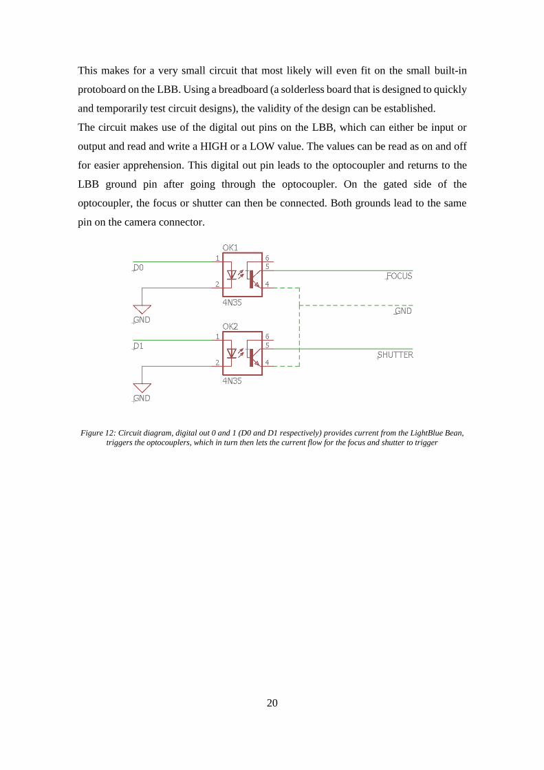
This makes for a very small circuit that most likely will even fit on the small built-in
protoboard on the LBB. Using a breadboard (a solderless board that is designed to quickly
and temporarily test circuit designs), the validity of the design can be established.
The circuit makes use of the digital out pins on the LBB, which can either be input or
output and read and write a HIGH or a LOW value. The values can be read as on and off
for easier apprehension. This digital out pin leads to the optocoupler and returns to the
LBB ground pin after going through the optocoupler. On the gated side of the
optocoupler, the focus or shutter can then be connected. Both grounds lead to the same
pin on the camera connector.
Figure 12: Circuit diagram, digital out 0 and 1 (D0 and D1 respectively) provides current from the LightBlue Bean,
triggers the optocouplers, which in turn then lets the current flow for the focus and shutter to trigger

21
Figure 13: Using a breadboard and an Arduino microcontroller to design the circuitry.
3.2.2 Designing the case
The comparable products on the market differ in size and design, but to differentiate from
them, the design requirements for the case could be:
1. Protect the circuit and hold the cable in place.
2. The battery compartment should be accessible.
3. The case should slot into the shoe on the camera.
4. As small as possible.
5. Cost-effective to manufacture.
Designing of the case happens in SolidWorks, a solid modeling computer-aided design
program. From SolidWorks, a 3D-file can be generated that software provided by 3D-
printer manufacturers can interpret and then slice layers and generate the G-code for the
3D-printer.
Attaching the case to the camera should be on top of the camera using a hot shoe that is
available on most cameras. The hot shoe is an ISO standard part, so once the part fits, it
should fit on any camera manufactured in the last 50 years. Ideally, the foot should also
be of some sort of metal as it will be subject to a lot of wear, but since that is above the
scope of this experiment, the foot will also be 3D printed. [47]

22
The parts of the design that will notice the most stress is the foot and any latches. These
need extra attention as the development progresses and are most likely to break in the
prototype.
To test what would be more suitable for this product, two slightly different case concepts
are designed. The first has an internal latch and requires the user to press the cover so that
the latches open and the top can be pulled off, but can be uniform in shape around the
case, and is more minimal in its design. The other design is a more functional design, with
the latch being external, with a small holding tab on the other side to keep the cover
steadfast. The second case is more functional and perhaps easier to use than the first
design. Both rely on a snug fit of the LBB inside the case, in such a way that no other
attachments are needed for the circuitry to not move on the inside. Quickly the first
concept is scrapped as the second one is much easier to print. The second concept was
also heavily inspired by the LightBlue Bean enclosure by user “jwags55” found on
Thingiverse.com [48], and such seems like a sounder option. The case will be created
from scratch in SolidWorks, with only visually referencing the enclosure found on
Thingiverse.com.
To achieve a proper fit around the LBB, the 3D model was imported from Punch Through
Designs website [42] and added to the assembly file. A new part was created from the
assembly file, and the outline of the LBB was copied into a sketch and offset by 2
millimeters outward, and then extruded 7,67 millimeters into to the bottom half of the
case. The object was then shelled, with 1,9 millimeters wall thickness. The profile on both
ends of the case was created by first adding material to one end by extrusion, and then
cutting away parts of it by looks instead of numbers and then mirrored to the other side.
Lastly, for the bottom part, a hot shoe mount was created by extruding a 16- by 18-
millimeter block out by 8 millimeters on the underside and then cutting out the two slots
on each side.
The upper part of the case is then created, again from the assembly. Referencing the
outline of the bottom part in a sketch, the general shape is then extruded up by 5
millimeters. A one-millimeter thick lip around the whole part is then extruded, that
extends over the bottom part by one millimeter. The end tab is then extruded on one end
and shaped to fit the bottom part by removing material from the assembly view and
referencing the bottom. A cavity is made for the board to sit in, using the LBB’s outline
and then cutting into the part up to 2 millimeters from the top. A small support beam is

23
added above the Bluetooth SoC, to hold down the LBB more when the case is shut. The
edges are then rounded on both the bottom and top part.
Figure 14: The case, with the LightBlue Bean inside of it, exploded in the assembly view inside SolidWorks.
3.2.3 Designing the software
As the main feature in direct contact with a user will be the software, through controlling
the device, and the feature that can be endlessly improved and iterated upon, a few
requirements for the software are established to create a simple but effective scope for
this project:
1. Fine control for triggering the focus and shutter separately.
2. Accept communication over Bluetooth.
The software is developed within the Arduino ecosystem, using their integrated
development environment. The language used is like a dialect of the programming
language C++. Using the software that Punch Through Design provides, the code (or
sketch as the Arduino program calls the code that is developed) can be then uploaded over
24
Bluetooth to the LBB. This makes it possible to iterate over the software while the LBB
is in its case, attached to the camera.
The structure programs in an Arduino system is as follows: A function called setup (code
line number 8, appendix 1) contains any initialization of any feature that you will need
and parameters that need to be on a specific value at the start. This setup function is run
only once, as the device is powered on. The loop function (line 15) contains your main
running code, and it loops through the code inside of the function until the device is turned
off. The loop speed is not a constant, as it is dependent on how much code there is to
execute. In this case, the setup contains the modes for the digital pins, as they can both
receive and send data, and the initialization of the pins so that they are not active.
Lines 4-6 initializes variables. The two first variables are the pin numbers established in
so that it is easier to read what is being activated. The last variable is related to Bluetooth
communication, which comes in later.
The setup function establishes first that the pins are for output only, and after that ensures
that there is no current running in the pins, establishing a baseline.
The loop function is doing two things; It is looking out after changes in a scratch
characteristic data point and if the data has been changed then triggers the camera. Scratch
characteristics are a low-level form of communication where a data point is stored on the
device (i.e. a characteristic variable) with a unique address, that is readable and writable
by external devices, over Bluetooth [49]. In order to tell the device that it should trigger
the camera, any value above 0 will then allow the if statement to run. Within the if
statement the LED is turned on to signal that the device got the command, and the pins
are triggered so that the camera has time to focus, before taking a picture. The LED is
then turned off and the scratch characteristic is then overwritten to 0, so that only one
picture is taken.
3.3 Iteration process
After the first design phase, the first prototype is built. In the building phase, multiple
unexpected issues occur and are fixed in order to finish the build. These issues are things
that only come to light when the plan is set to motion when theory meets practice. After
the first parts are built, enough feedback has accumulated that the iteration process can
begin for the product.

25
3.3.1 Circuit
The circuit planned in figure 7 was modified slightly. Since the area of the protoboard on
the LBB is so small, the digital outputs had to be changed from D0 and D1 to D1 and D4
respectively. This changes nothing in the software side, except for the variables. The
circuitry is simple but connecting the camera cable to the LBB required some thought.
One alternative was to solder the leads on to the board directly, but this would make
modifying cables and removing the LBB from its case much more difficult. A connector
was then considered and effectively implemented. A simple 2.54-millimeter one row 4-
pin connector was chosen for its small footprint and easy adaptability. The cable
connecting the camera and the LBB is taken from a manual wired remote trigger and
shortened. The leads for the female connector are crimped on to each of the three wires
in the cable.
Figure 15: The circuit soldered on to the LBB, a 2-euro coin for scale
3.3.2 Case
Since the cases were designed without a connector in mind, the hole for the connector
must be implemented. The connector is put on the upper part of the case, in connection
with the internal ceiling. The connector also serves a secondary purpose on holding the
LBB quite firmly in place, although it does not see a lot of stress since the LBB already
sits very snugly within the case.
Another small feature is considered: A hole that allows for the LED to shine through, but
this is proven to be unnecessary as the LED shines through the white PLA even at full
thickness.
26
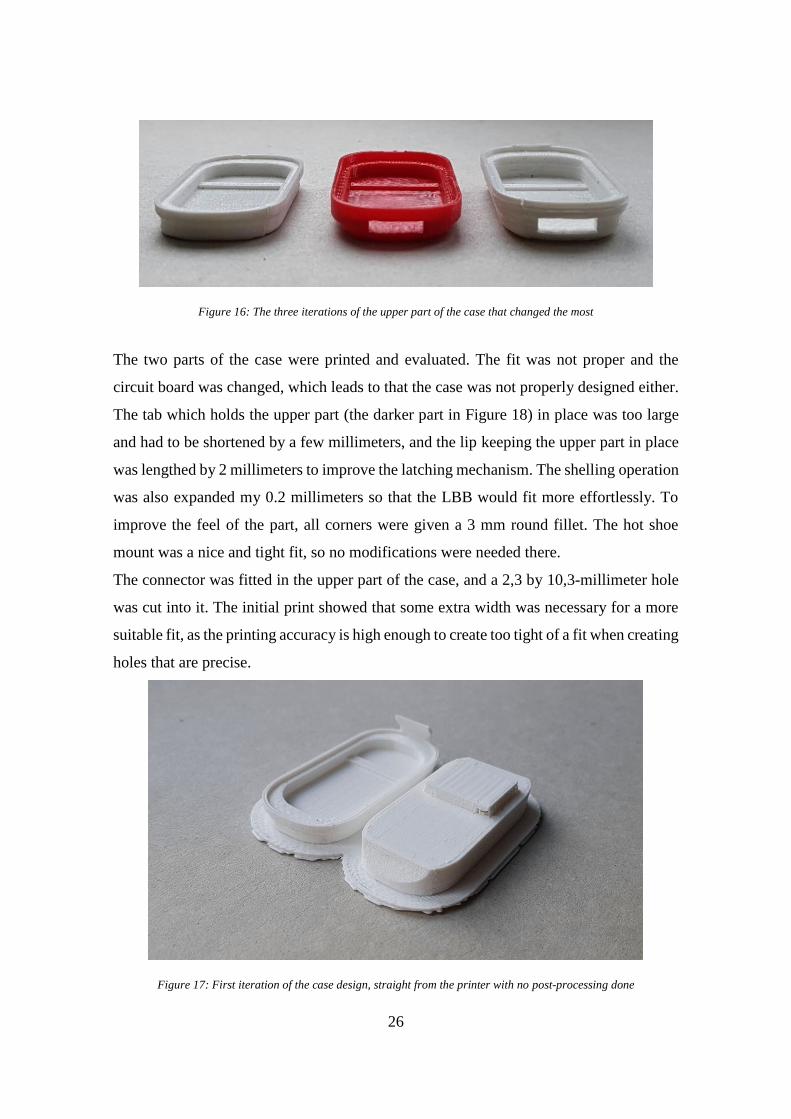
Figure 16: The three iterations of the upper part of the case that changed the most
The two parts of the case were printed and evaluated. The fit was not proper and the
circuit board was changed, which leads to that the case was not properly designed either.
The tab which holds the upper part (the darker part in Figure 18) in place was too large
and had to be shortened by a few millimeters, and the lip keeping the upper part in place
was lengthed by 2 millimeters to improve the latching mechanism. The shelling operation
was also expanded my 0.2 millimeters so that the LBB would fit more effortlessly. To
improve the feel of the part, all corners were given a 3 mm round fillet. The hot shoe
mount was a nice and tight fit, so no modifications were needed there.
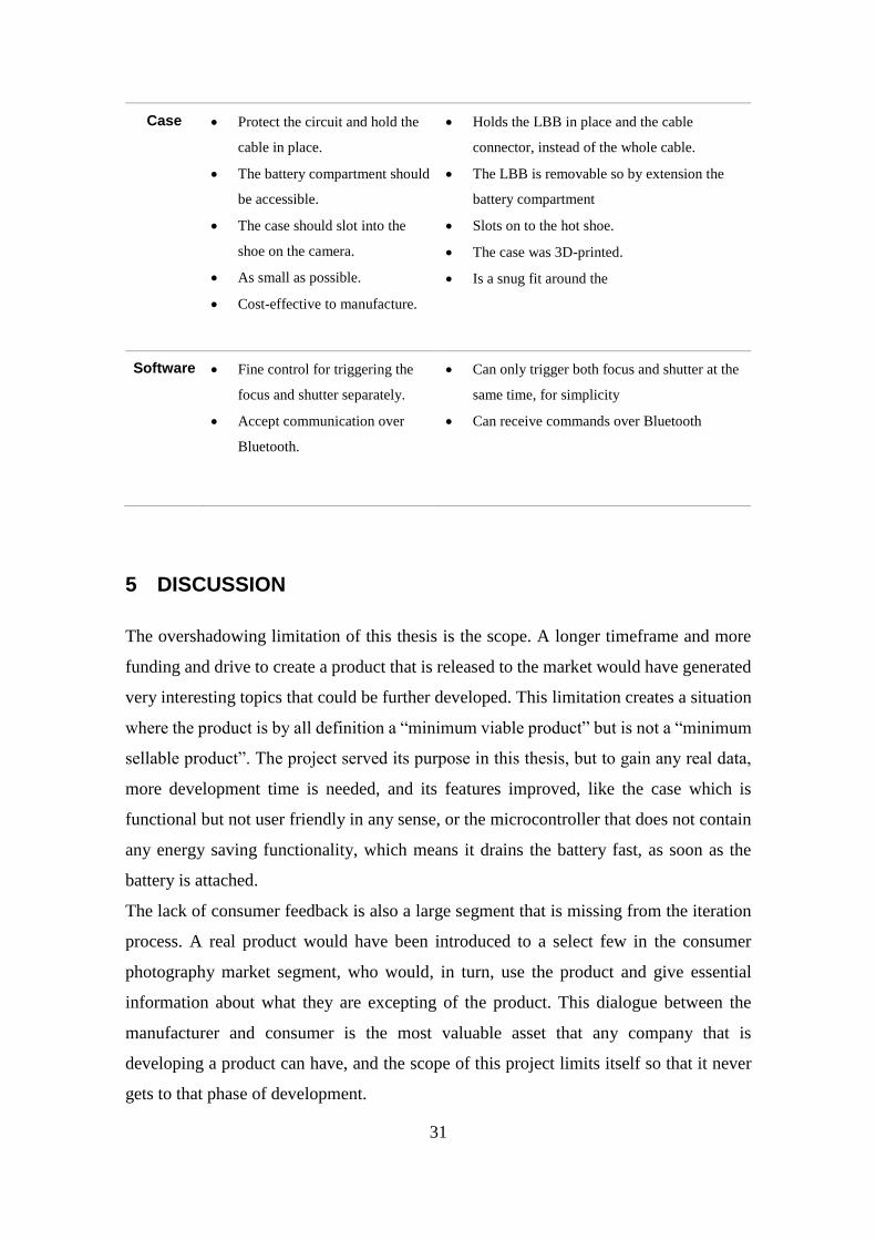
The connector was fitted in the upper part of the case, and a 2,3 by 10,3-millimeter hole
was cut into it. The initial print showed that some extra width was necessary for a more
suitable fit, as the printing accuracy is high enough to create too tight of a fit when creating
holes that are precise.
Figure 17: First iteration of the case design, straight from the printer with no post-processing done

27
The upper part was then iterated over again and reprinted. This resulted in the final form
and prototype part of the case. In order to fit the LBB, the upper part had to be taller, and
the location of the connector pins was realigned so that the pins naturally extend out from
the hole. The hole was also enlarged, as not to make the connector fit too tight.
The holding tabs on all three top parts that were printed resulted in quick failure. This
was partly because of the nature of the FDM printing, as the layering was oriented in such
way that the part was placed on top of the rim, and not integrated properly into the rest of
the case. Using an SLA printer could perhaps have avoided the issue, but since for this
prototype the tab seemed to provide only a little bit of support, the issue was ignored, and
considered non-important for this particular experiment.
Figure 18: The case in SolidWorks
3.3.3 Software
The software was not changed as it was working adequately. A custom mobile application
was considered but then concluded that it was out of the scope of this thesis. A rough
draft was done for the phone in Android Studio, but no additional time was put into it.
3.4 Production
To create the layers for the FDM to print the part, MakerBot’s own Print program was
used. The two halves of the case were then placed out on the printing surface in the

28
program to minimize the footprint. The upper part of the case was easy to realize which
side would be up for the print to work. The lower part required more thought, with a
precision part on one side and a cavity on the other. In the end, the hot shoe connector
required more precision, so minimal amounts of support structures created a more
accurate print. The program automatically added the supports, but the default settings for
printing did not add support for the hot shoe connector, or on the cavity. This was solved
by enabling the “Supports” option, under the “Supports and Bridging” sub-menu. The
rest of the options were left untouched. The software gave an estimation of 1 hour and 13
minutes, and approximately 16 grams of polylactic acid (PLA) was to be used. The print
was then initiated and was completed in 1 hour and 11 minutes1. The support structures
were then removed, using knives and pliers. The surface finish was not ideal, but very
capable of showing the core idea of the product, so no additional post-processing was
deemed necessary.
Figure 19: The final product, opened. Bottom part is on the left and top part on the right
1 It is possible that the software included the pre-print routine in the estimate, in which case the complete
printing time was the same as the estimate.

29
4 RESULTS
The research questions laid out in the introduction can then be evaluated and discussed in
this subsection. The questions asked were:
RQ1: Can the product development technique “minimum viable product” be used for
hardware projects in the same manner as it is used for software projects?
RQ2: What are the available tools for making a small hardware project?
RQ3: How do you iterate on hardware?
Answering the first research question, this thesis and the literature overview for MVP in
hardware shows that there clearly is a possibility to use the development technique in
such a way that you can follow its principals. The iteration cycle is not nearly as fast as it
can be in its software state, but these are the realities of making a physical product.
Manufacturing has always been a time-consuming process, but with the aid of modern
manufacturing methods, the time it takes to have a working prototype to evaluate has
been improved by a large margin.
Figure 20: The finalized product, seated in the hot shoe on a camera. The cable goes from the product to the camera
remote socket
This then leads to the second question, where the tools quite clearly become defined in
this thesis. Additive manufacturing (or rapid prototyping) has improved significantly

30
since their introduction to the manufacturing world and become much cheaper in the same
process. This leads to the realization that anyone could with minimal effort and costs
produce a quick prototype for an idea, without the need to create everything from scratch.
The different additive manufacturing methods also make it so that if one method proves
to be bad for that product, most likely another method will not have the same difficulties.
For electronics, the Arduino project has helped to create an easy-to-access and cheap way
for the complete beginner to create something with microcontrollers and automation, and
with their open source mentality have made it possible for even more niche products to
emerge based on the platform, with the LightBlue Bean as a prime example of this.
The last question is answered by the small project completed for this thesis. The largest
iteration and most demanding part was by far the case, which had to be printed and
iterated upon multiple times. But again, the methods available creates an easy way of
discovering just what is wrong and how to remedy it in the designs. Being able to
physically inspect the product in its prototype stages actually may make it easier to define
the next milestone which then can be completed quickly by just changing some
parameters on the designs. The accurate reproduction of the 3D-printing also inspires
confidence in that what you create in your CAD-software is going to look similar when
you get it in your hands. Defining the requirements of each part also help to keep the
product more focused and limits the possible scope of the project. The final product can
then also be compared to the original idea (Table 1) and can also be used as a tool for
learning how designing for the real world differs from just making digital designs that
never get made.
Table 1: Table of requirements as stated in the designing phase and the results of production
Part Original requirements Final features
Circuit • Allow the microcontroller to
trigger the camera shutter.
• As cheap as possible.
• As small of a footprint as
possible.
• Reliable
• By giving signal to the right pin the focus or
shutter triggers.
• Costs are tied to the microcontroller, rest of
circuitry is only roughly a percentage of the
price
• No additional boards needed other than the
LBB
• Simple circuitry creates a reliable product
31
Case • Protect the circuit and hold the
cable in place.
• The battery compartment should
be accessible.
• The case should slot into the
shoe on the camera.
• As small as possible.
• Cost-effective to manufacture.
• Holds the LBB in place and the cable
connector, instead of the whole cable.
• The LBB is removable so by extension the
battery compartment
• Slots on to the hot shoe.
• The case was 3D-printed.
• Is a snug fit around the
Software • Fine control for triggering the
focus and shutter separately.
• Accept communication over
Bluetooth.
• Can only trigger both focus and shutter at the
same time, for simplicity
• Can receive commands over Bluetooth
5 DISCUSSION
The overshadowing limitation of this thesis is the scope. A longer timeframe and more
funding and drive to create a product that is released to the market would have generated
very interesting topics that could be further developed. This limitation creates a situation
where the product is by all definition a “minimum viable product” but is not a “minimum
sellable product”. The project served its purpose in this thesis, but to gain any real data,
more development time is needed, and its features improved, like the case which is
functional but not user friendly in any sense, or the microcontroller that does not contain
any energy saving functionality, which means it drains the battery fast, as soon as the
battery is attached.
The lack of consumer feedback is also a large segment that is missing from the iteration
process. A real product would have been introduced to a select few in the consumer
photography market segment, who would, in turn, use the product and give essential
information about what they are excepting of the product. This dialogue between the
manufacturer and consumer is the most valuable asset that any company that is
developing a product can have, and the scope of this project limits itself so that it never
gets to that phase of development.

32
Further research could also be done on scaling production up, as in what steps are to be
taken from the final test prototype to the first production prototype. Any mass production
is most likely not viable to 3D-print, and more robust and quicker ways of creating parts
have to be developed. Injection molding would be the most likely option for this
production, as the parts are small and could be modified to make an even simpler mold.
The LightBlue Bean also contains a plethora of useless features for this project, like
temperature sensors and accelerometers, so making the circuitry smaller would also create
an even smaller product, and the iteration process would continue.
Furthermore, a large study of real-life products and their initial development would be
very interesting to conduct, from the ideation to creation of the finalized product, and then
the life cycle, and evolution, of that product after it has been created. As an example, the
development of the iPod by Apple, or the Nest thermostat by Nest Labs.
6 CONCLUSIONS
Producing a hardware product is challenging and requires a firm desire to introduce
something special to the market. By avoiding common pitfalls of development (over
thinking and generalizing the product too much) the challenges can be reduced by a
fraction, but the main issue is still the time it takes to iterate over something so intricate
as how a product feels in your hand. This is something that you cannot see on a screen or
on paper, it is something that requires a multitude of tests and modifications. The scope
of this thesis does not allow for too many iterations of the design as required, but still
provides a valuable lesson in designing physical products. Rapid prototyping
technologies provide a solution, but it cannot reach the same elasticity of software
development where you can have hundreds of different versions over a week of
development. These are but the harsh realities of producing hardware to the market.
The minimum viable product development method as is does not support the hardware
development procedures. But by taking the core principles and modifying them, a more
suiting work model can be discovered:

33
1. Do one thing and do it well.
By focusing on one feature (in the example in this thesis, trigger a shutter on a camera)
makes it more likely that the feature is relevant. In comparison if you would make a
product that can take the picture, modify it, upload it to a cloud service and edit it,
how many would perhaps just use it for the first feature? With one feature you
guarantee that the customers that buy that product want it for one reason, which then
gives you good feedback on what to develop next.
2. Engage customers and listen to them.
Developing features with a metaphorical blindfold on creates situations where you do
not know if a feature is relevant. Perhaps the customers do not think that some feature
that you spend a lot of time on is that essential for the function of the product, thus
making you essentially waste time unnecessarily.
3. Use the prototype for extended times.
Avoiding rushing the product to production before it feels right will vastly improve
the usability and life time of the product. A lot of issues and use cases do not occur
until extended use. Money is always an issue, but it’s better to have a good product
on the market than something that is falling apart, and no one will invest in.
4. Try thinking on a smaller scale.
Since scaling hardware is much harder than scaling software, focusing on a smaller
market or scale keeps the production cost down. The unit price for manufacturing will
go down with larger orders but selling out the stock and not having the product
immediately available might even create a larger desire for the product if it impresses
users. Smaller orders can even be locally produced, instead of going to a mega-factory
in one of the production countries, creating an ecological advantage as well, and less
cost for moving the product from factory to warehouse. The pressure to produce
something to sell worldwide does more damage than opportunities, with many of the

34
large companies that are dominating the market today either have started from
producing something completely different from the product they sell today or started
on an extremely small scale. It is easier to scale production up on local success than
it is to ramp it down after a failure.
These four principals were named the Edmund principles2 and demonstrate a new way of
thinking when it comes to building a product, modified from the minimum viable product
institution that is the dominating thinking process on the market at this time. These
principles promote longevity instead of instantaneous profit, and sustainability instead of
mindless consumption. Hardware is hard, but with rapid prototyping and an era of
unlimited knowledge and resources, it does not have to be impossible.
2 In memory of my late grandfather

35
7 ABSTRAKT
Detta slutarbete undersöker ifall produktutvecklingsteorin ”minimum viable product”
(direkt översatt till enklaste gångbara produkten, förkortat till MVP), som oftast används
inom programvaruutvecklingsindustrin, kan användas för utveckling av fysiska
produkter. Bakgrunden till detta experiment kommer från den svåra marknaden som nya
företag hamnar i, ifall de försöker introducera nya fysiska produkter. Även när företagen
får investeringar visar statistiken att upp till 70% av företag går i konkurs.
Intressanta hjälpmedel har dykt upp på marknaden de senaste fem åren, som underlättar
utvecklingsprocessen. Friformsframställning och mikrokontrollerkort har utvecklats till
kraftiga verktyg som produktutvecklaren kan använda för att snabbt skapa en prototyp
och få konstruktiv kritik om vad produkten kan behöva för att bli en succé.
I litteraturöversikten går slutarbetet igenom tre stora områden: Friformsframställning,
MVP och mikrokontrollerkort. Friformsframställning är ett så stort område, vilket leder
till att endast de tre grundläggande och mest sannolika alternativen väljs för närmare
granskning. Metodiken och för- och nackdelar förklaras för varje alternativ. Basprincipen
för friformsframställning är den samma; ett datorprogram skär den tredimensionella
modellen till tunna skivor, vilka då kan printas ut på varandra, lager för lager, för att skapa
en tredimensionell produkt. Hur lagren produceras varierar sedan.
Stereolitografi (SLA) är den första moderna friformsframställningstekniken som
utvecklades redan på 80-talet. Materialet flyter i en behållare, och en laserstråle härdar ett
lager av modellen till en byggplattform. Beroende på modellen för maskinen så sjunker
eller lyfts byggplattformen sedan, och nästa lager härdas, och så vidare, tills alla lager har
härdats. Objektet måste sedan härdas färdigt, för processen härdar inte lagren fullständigt.
Detta ger mera styrka mellan lagren för de kan forma bindningar i alla riktningar.
Selective Laser Sintering (SLS) baserar sig mycket på samma koncept som
stereolitografi, men istället för att ha materialet i flytande form, är det pulver istället.
Pulvret är uppvärmt i en behållare och en laserstråle smälter och därmed sintrar pulvret
till en homogen del. Byggplattformen sjunker, och ett tunt lager av pulver läggs på och
processen upprepar sig. Pulvret kan återanvändas men lider ifall de värms upp ett flertal
gånger och därmed blir oanvändbart. Pulvret stöder objektet medan de printas, vilket

36
betyder att inga stödstrukturer behövs, men ytan blir porös, och lagren förblir synliga, för
de inte formar extra bindningar mellan lagren.
Fused Deposit Modelling (FDM) är den mest populära metoden för
friformsframställning. Metoden använder minst möjliga mängd material, och lägger
materialet ut på byggplattformen genom extrudering ur ett uppvärmt munstycke.
Materialet kyls snabbt ner på grund av temperaturs skillnaden, och stelnar på plattformen,
och nästa lager kan direkt läggas ut. Stöd behövs endast om objektet har hängande delar,
och oftast hjälper det att vända på objektet. Likt SLS så förblir lagren synliga, men ytorna
är inte porösa och med hjälp av efterbehandling kan ytan bli slät ifall det behövs.
Minimum viable product är en teknik som Frank Robinson introducerade år 2001, men
blev populär med Eric Ries book ”The Lean Startup” år 2011. Konceptet går ut på att
istället för att gissa vad kunder behöver, och vill ha, så introduceras de till produkten så
snabbt som möjligt. Ries kallar dessa kunder till ”visionärer”, för de ser inte produkten
endast hur den fungerar och ser ut i början, utan vad den kan uppnå efter längre
utveckling. Dessa kunder accepterar en sämre produkt för de vill delta i
produktutvecklingsprocessen genom att ge kritik. Genom att engagera kunder tidigt i
processen, klarar man av att skärpa sitt fokus mot den mest väsentliga delen av produkten.
Processen sköts igenom att iterera, i en evig cykel. Från att lösa ett problem till att bygga
en prototyp, som kunder engageras med och ger kritik, och tillbaka till att lösa de problem
som uppstod från kritiken.
Mikrokontrollrar är fullständiga kretskort, med processor, minne och programminne,
integrerade på en och samma kiselbricka. Ett mikrokontrollerkort är sedan nästa steg från
detta, där allting som behövs för att kommunicera med mikrokontrollerna är kopplade till
större och enklare in- och utgångar, som till exempel USB. Mikrokontrollerkort är därmed
ett verktyg för att experimentera och snabbt utveckla en liten produkt.
Som ett experiment utvecklas en produkt. Konceptet utgår från att äldre kameror inte har
möjlighet att kommunicera trådlöst över Bluetooth, och med att tillverka en modul som
hämtar den moderna funktionen till äldre modeller ökar man livslängden och
användningsmöjligheten för kameror. En marknadsanalys och en SWOT analys utförs
och två huvudsakliga produkter existerar på marknaden. Till slut delas produkten in till

37
tre delar (kretskortet, fodralet och mjukvaran) för att separera iterationsprocessen och
underlätta utvecklingen. Produkten utvecklas sedan enligt MVP teorin, var varje del
itereras över ända tills produkten blir användbar. De flesta iterationscykeln går till fodralet
och dess form.
Experimentet tog slut efter att produkten var användbar. Detta leder till att MVP inte blev
fullständigt utvärderat, p.g.a. att produkten aldrig visades till kunder. Problemet låg mera
i tidsbrist än i fel i utvärderingssättet. MVP fungerar även med fysiska produkter, men
man måste vara beredd att inte klara av en lika snabb itereringscykel. En större investering
krävs, men med smartare tidsanvändning och mera intensivt fokus på att utveckla en
produkt som gör en sak väl istället för att vara så mångsidig som möjligt. För att underlätta
processen och fokusen skapades fyra punkter vars uppgift är att komplettera ideologin
bakom MVP.
1. Gör en sak, men gör den väl.
2. Engagera kunderna och lystna på deras bekymmer.
3. Använd prototypen för så länge det är möjligt.
4. Försök tänka i mindre banor.
Med dessa punkter kan jobbet för att skapa ett hållbart företag och en välgjord
produktlinje bli enklare. Punkterna hyllar hållbarhet och tanken om att bra produkter tar
en lång tid att utveckla.

38
8 REFERENCES
[1] CB Insights, "Hardware Is Hard - So How Can Consumer Hardware Startups
Succeed?," CB Insights, 27 September 2017. [Online]. Available:
https://www.cbinsights.com/research/report/hardware-startups-failure-success/.
[Accessed 19 December 2017].
[2] Punch Through Design, "Bean - Punch Through," Punch Through Design, 2017.
[Online]. Available: https://punchthrough.com/bean. [Accessed 19 December
2017].
[3] J. Borrello and P. Backeris, "Rapid Prototyping Technologies," in Rapid
Prototyping in Cardiac Disease, Springer, 2017, pp. 41-49.
[4] F. Grieser, "What Resolution Can 3D Printers Print?," All3DP, 29 December 2015.
[Online]. Available: https://all3dp.com/3d-printer-resolution/. [Accessed 8
February 2018].
[5] R. Brockotter, "Key design considerations for 3D Printing," 3D hubs, [Online].
Available: https://www.3dhubs.com/knowledge-base/key-design-considerations-
3d-printing. [Accessed 15 March 2018].
[6] C. W. Hull, "Apparatus for production of three-dimensional objects by
stereolithography". United States of America Patent US4575330A, 08 August 1984.
[7] C. A. G. Lengua, "History of Rapid Prototyping," in Rapid Prototyping in Cardiac
Disease, Springer, 2017, pp. 3-7.
[8] Formlabs, "The Ultimate Guide to Stereolithography (SLA) 3D Printing,"
Formlabs, [Online]. Available: https://formlabs.com/blog/ultimate-guide-to-
stereolithography-sla-3d-printing/. [Accessed 15 March 2018].
[9] G. V. Salmoria, C. H. Ahrens, M. Fredel, V. Soldi and A. T. N. Pires,
"Stereolithography somos 7110 resin: mechanical behavior and fractography of

39
parts post-cured by different methods," Polymer Testing, vol. 24, no. 2, pp. 157-
162, 2005.
[10] C. Armstrong, "How to design parts for SLA 3D Printing," 3D Hubs, [Online].
Available: https://www.3dhubs.com/knowledge-base/how-design-parts-sla-3d-
printing. [Accessed 15 March 2018].
[11] F. B. Prinz, C. L. Atwood and R. F. Aubin, "TEC/WTEC panel on rapid prototyping
in Europe and Japan," Rapid Prototyping Association of the Society of
Manufacturing Engineers, 1997.
[12] Encyclopaedia Britannica, "Sintering," Encyclopædia Britannica, Inc. , 2018.
[Online]. Available: https://www.britannica.com/technology/sintering. [Accessed 7
March 2018].
[13] C. R. Deckard, "Method and apparatus for producing parts by selective sintering".
United States of America Patent US4863538 A, 5 September 1989.
[14] S. F. S. Shirazi, S. Gharehkhani, M. Mehrali, H. Yarmand, H. S. C. Metselaar, N.
A. Kadri and N. A. A. Osman, "A review on powder-based additive manufacturing
for tissue engineering: selective laser sintering and inkjet 3D printing," Science and
Technology of Advanced Materials, vol. 16, no. 3, 2015.
[15] A. Wheeler, "Coming Soon: a $5,000 SLS 3D Printer From Sinterit," 3D printing
Industry, 23 April 2015. [Online]. Available:
https://3dprintingindustry.com/news/coming-soon-a-5000-sls-3d-printer-from-
sinterit-47428/. [Accessed 8 February 2018].
[16] S. Oceanz, "How to design parts for SLS 3D Printing," 3D Hubs, [Online].
Available: https://www.3dhubs.com/knowledge-base/how-design-parts-sls-3d-
printing. [Accessed 15 March 2018].
[17] R. Goodridge, C. Tuck and R. Hague, "Laser sintering of polyamides and other
polymers," Progress in Materials Science, vol. 57, no. 2, pp. 229-267, 2012.

40
[18] L. Columbus, "The State Of 3D Printing, 2017," Forbes, 23 May 2017. [Online].
Available: https://www.forbes.com/sites/louiscolumbus/2017/05/23/the-state-of-
3d-printing-2017/#7c9f6da057eb. [Accessed 8 February 2018].
[19] S. S. Crump, "Apparatus and method for creating three-dimensional objects".
United States of America Patent US5121329A, 30 October 1989.
[20] 3D-Print Today, "What is Fused Deposition Modeling (FDM)?," 3D-Print Today,
01 Mars 2015. [Online]. Available: http://www.3d-
print.today/What_is_Fused_Deposition_Modeling. [Accessed 18 January 2018].
[21] RepRap, "RepRap," RepRap, 31 October 2017. [Online]. Available:
http://reprap.org/. [Accessed 8 February 2018].
[22] B. Hudson, "How to design parts for FDM 3D Printing," 3D Hubs, [Online].
Available: https://www.3dhubs.com/knowledge-base/how-design-parts-fdm-3d-
printing. [Accessed 15 March 2018].
[23] SyncDev, "A Proven Methodology to Maximize Return on Risk," SyncDev,
[Online]. Available: http://www.syncdev.com/minimum-viable-product/.
[Accessed 12 March 2018].
[24] E. Ries, The Lean Startup: How Today’s Entrepreneurs Use Continuous Innovation
to Create Radically Successful Businesses, Crown Publishing Group, 2011.
[25] H. Kniberg, "Making sense of MVP (Minimum Viable Product) – and why I prefer
Earliest Testable/Usable/Lovable," Crisp AB, 25 January 2016. [Online].
Available: https://blog.crisp.se/2016/01/25/henrikkniberg/making-sense-of-mvp.
[Accessed 12 March 2018].
[26] J. Münch, F. Fagerholm, P. Johnson, J. Pirttilahti, J. Torkkel and J. Järvinen,
"Creating Minimum Viable Products in Industry-Academia Collaborations," Lean
Enterprise Software and Systems. Lecture Notes in Business Information
Processing, vol. 167, 2013.

41
[27] P. Walker, "Early Access popularity growing, but only 25% have released as a full
game," Gamer Network, 14 November 2014. [Online]. Available:
https://www.gamesindustry.biz/articles/2014-11-13-early-access-popularity-
growing-but-only-25-percent-have-released-as-a-full-game. [Accessed 12 March
2018].
[28] P. Walker, "Steam Early Access is hitting its stride - EEDAR," Gamer Network, 11
March 2016. [Online]. Available: https://www.gamesindustry.biz/articles/2016-03-
11-steam-early-access-is-hitting-its-stride-eedar. [Accessed 12 March 2018].
[29] Wingify, "The Complete Guide to A/B Testing," Wingify, [Online]. Available:
https://vwo.com/ab-testing/. [Accessed 12 March 2018].
[30] Cambridge University Press, "Hardware Meaning in the Cambridge English
Dictionary," Cambridge University Press, 2018. [Online]. Available:
https://dictionary.cambridge.org/dictionary/english/hardware. [Accessed 25
January 2018].
[31] M. Barros, "Here's How to Make Hardware Startups More Than Just a Fad," Wired,
24 September 2013.
[32] M. Barros, "Harware [sic] MVP – Fastest Path To Cash," 25 September 2013.
[Online]. Available: http://marcbarros.com/hardware-mvp-fastest-path-to-cash/.
[Accessed 15 March 2018].
[33] A. Trevennor, Practical AVR Microcontrollers, Apress, 2012.
[34] Wikipedia, "File:ATMEGA328P-PU.jpg," Wikipedia, 9 October 2009. [Online].
Available: https://en.wikipedia.org/wiki/File:ATMEGA328P-PU.jpg. [Accessed
20 March 2018].
[35] T. Foxworth, "Hardware Fundamentals: what exactly is a microcontroller?," 24
April 2017. [Online]. Available: https://medium.freecodecamp.org/hardware-
fundamentals-what-exactly-is-a-microcontroller-8a502a3650dc. [Accessed 20
March 2018].

42
[36] Arduino, "Arduino Uno rev3," Arduino, [Online]. Available:
https://store.arduino.cc/arduino-uno-rev3. [Accessed 20 March 2018].
[37] D. Kushner, "The Making of Arduino," IEEE Spectrum, 26 October 2011. [Online].
Available: https://spectrum.ieee.org/geek-life/hands-on/the-making-of-arduino.
[Accessed 20 March 2018].
[38] Arduino, "Compare board specs," Arduino, [Online]. Available:
https://www.arduino.cc/en/Products/Compare. [Accessed 20 March 2018].
[39] Arduino, "Shields," Arduino, [Online]. Available:
https://www.arduino.cc/en/Main/ArduinoShields. [Accessed 20 March 2018].
[40] Punch Through Design, "Technical Specs," [Online]. Available:
https://punchthrough.com/bean/docs/guides/getting-started/tech-specs/. [Accessed
22 March 2018].
[41] Punch Through Design, "Prototype to production," [Online]. Available:
https://punchthrough.com/bean/docs/guides/everything-else/proto-to-prod/.
[Accessed 22 March 2018].
[42] Punch Through Design, "Hardware Files - Punch Through," 2017. [Online].
Available: https://punchthrough.com/bean/docs/guides/everything-else/hardware-
files/. [Accessed 18 December 2017].
[43] Arsenal, "Meet Arsenal, the Smart Camera Assistant," [Online]. Available:
https://witharsenal.com/. [Accessed 10 April 2018].
[44] Tether Tools, "Case Air Wireless Tethering System," [Online]. Available:
https://www.tethertools.com/product/case-air-wireless-tethering-system/.
[Accessed 10 April 2018].
[45] Electronic Tutorials, "Optocoupler Tutorial," AspenCore, [Online]. Available:
https://www.electronics-tutorials.ws/blog/optocoupler.html. [Accessed 10 April
2018].

43
[46] P. Miller, "Build Notes for DIY Nikon GPS," Peter Miller Photography, 2008.
[Online]. Available: http://www.petermillerphoto.com/nikongps/nikongps2.html.
[Accessed 18 January 2018].
[47] ISO 518:2006: Photography -- Camera accessory shoes, with and without electrical
contacts, for photoflash lamps and electronic photoflash units, International
Organization for Standardization, 2006.
[48] jwags55, "LightBlue Bean Enclosure," MakerBot, 29 July 2014 . [Online].
Available: https://www.thingiverse.com/thing:410473/#files. [Accessed 12 April
2018].
[49] K. Townsend, "Introduction to Bluetooth Low Energy," Adafruit, 4 May 2015.
[Online]. Available: https://learn.adafruit.com/introduction-to-bluetooth-low-
energy/gatt. [Accessed 13 April 2018].
[50] M. Currey, "Activating the shutter release," 2013. [Online]. Available:
http://www.martyncurrey.com/activating-the-shutter-release/. [Accessed 21
October 2017].
[51] G. Ronalds, "Making a Nikon Camera Remote Control Release," All Digital
Photography, 2010. [Online]. Available: http://www.alldigi.com/2010/04/making-
a-nikon-camera-remote-control-release/. [Accessed 21 October 2017].
[52] Custompart, "Stereolithography (SLA)," 2008. [Online]. Available:
http://www.custompartnet.com/wu/stereolithography. [Accessed 10 December
2017].
[53] C. Cheng and R. Auri, "Hacking digital cameras," Wiley, 2005, pp. 3-46.
[54] J. Helmi, 3D Printing - International Benchmarking for Arcada, Arcada, 2015.
[55] D. R. Moogk, "Minimum Viable Product and the Importance of Experimentation in
Technology Startups," Technology Innovation Management Review, pp. 23-26,
March 2012.

44
APPENDIX 1. remotecontroller.ino
1. // remotecontroller.ino 2. // Listens for any value above 1 from scratch 1 3. 4. int focus = 1; 5. int shutter = 4; 6. uint32_t scratch = 0; 7. 8. void setup() { 9. pinMode(focus, OUTPUT); 10. pinMode(shutter, OUTPUT); 11. digitalWrite(focus, LOW); 12. digitalWrite(shutter, LOW); 13. } 14. 15. void loop() { 16. 17. scratch = Bean.readScratchNumber(1); 18. 19. if (scratch > 0){ 20. Bean.setLed(50, 0, 0); 21. digitalWrite(focus, HIGH); 22. delay(1000); 23. 24. Bean.setLed(100, 0, 0); 25. digitalWrite(shutter, HIGH); 26. delay(1000); 27. digitalWrite(shutter, LOW); 28. digitalWrite(focus, LOW); 29. 30. Bean.setLed(0, 0, 0); 31. Bean.setScratchNumber(1, 0); 32. } 33. }