Rapid Prot 23
37
Rapid Prototyping (RP) compiled by Michelle Griffith - Sandia National Laboratories adapted by John Lamancusa - Penn State
-
Upload
sai-prakash -
Category
Documents
-
view
16 -
download
0
description
rapid prototyping types
Transcript of Rapid Prot 23

Rapid Prototyping (RP)
compiled by Michelle Griffith - Sandia National Laboratories
adapted by John Lamancusa - Penn State

RP SequenceRP Sequence
• CAD solid model• ‘.STL’ file• Slicing the file• Final build file• Fabrication of part• Post processing

CAD Solid ModelCAD Solid Model
• Solid model or closed surface model required

.STL File.STL File
• Software generates a tessellated object description
• File consists of the X, Y, Z coordinates of the three vertices of each surface triangle, with an index to describe the orientation of the surface normal
• Support generation to hold overhung surfaces during build

solid ascii facet normal 0.000000e+000 -1.018113e-001 -9.948037e-001
outer loop vertex 6.413766e+000 9.540946e+000 4.174942e-001 vertex 6.663766e+000 9.540946e+000 4.174942e-001 vertex 6.413766e+000 9.467294e+000 4.250320e-001
endloop endfacet
facet normal 1.587419e-015 -1.018113e-001 -9.948037e-001 outer loop
vertex 6.413766e+000 9.467294e+000 4.250320e-001 vertex 6.663766e+000 9.540946e+000 4.174942e-001 vertex 6.663766e+000 9.467294e+000 4.250320e-001
endloop endfacet
..

Slicing the FileSlicing the File
• Series of closely spaced horizontal planes are mathematically passed through the .stl file
• Generate a ‘.sli’ file : a series of closely spaced 2D cross-sections of the 3D object
• Typical Z thickness 0.006” (0.150 mm)• Other Parameters chosen
=fn(RP technology)

• Part sliced• Supports sliced• RP technology parameters set
• layer thickness, scan speed,...
• Send file to RP machine
Final Build FileFinal Build FilePart
Supports
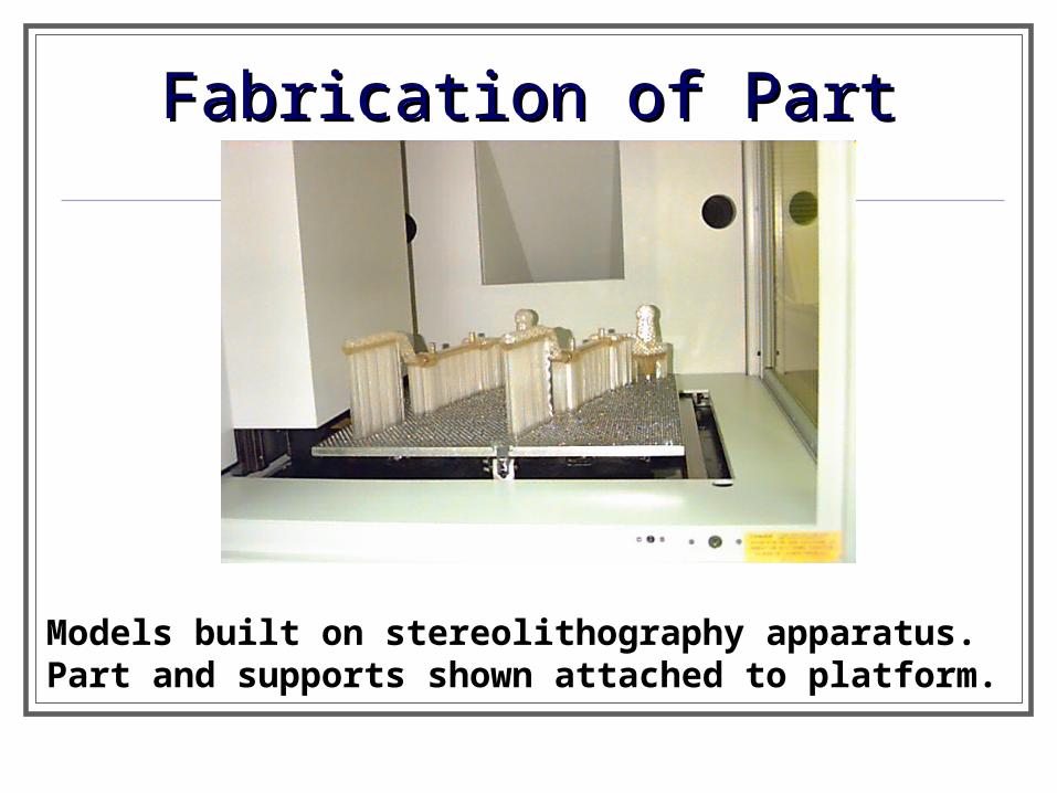
Fabrication of PartFabrication of Part
Models built on stereolithography apparatus. Part and supports shown attached to platform.

Post-processingPost-processing
• Removal of part from platform
• Removal of supports from part
• Cleaning of part (wiping, rinsing, ... )
• Finishing part (curing, sanding, polishing, … )

Rapid Prototyping TechnologiesRapid Prototyping Technologies
• Several technologies Stereolithography (SL)
Laminated Object Manufacturing (LOM)
Selective Laser Sintering (SLS)
Fused Deposition Modeling (FDM)
Solid Ground Curing (SGC)3D Printing (3DP)
Laser Engineered Net Shaping (LENS)

Stereolithography (SLA)Stereolithography (SLA)

Stereolithography (SLA)Stereolithography (SLA)
• 3D Systems, Valencia, CA• patent 1986, beginning of RP• photopolymerization using UV laser• epoxies, acrylates (brittle)• excellent accuracy < 50 mm• relatively slow• $179,000 (103 in3) to $799,000 (203 in3)


SLA Video http://www.acucast.com/video.htm

Laminated Object ManufacturingLaminated Object ManufacturingLOMLOM

• Helisys, Torrance, CA (out of business in 2000, serviced by a successor organization, Cubic Technologies)
• patent 1988• cross-sectional cutouts fused together• paper, plastic (new)• accuracy ±0.005”
Laminated Object ManufacturingLaminated Object Manufacturing(LOM)(LOM)
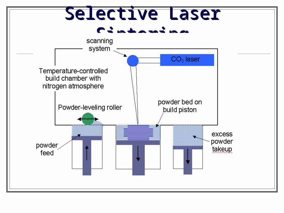
Selective Laser SinteringSelective Laser Sintering

• DTM, Austin, TX, now 3D systems• patent 1989, Carl Deckard’s master’s thesis
• fusing polymeric powders with CO2 laser
• accuracy 160 mm• no supports• polycarbonate, nylon, wax, glass-filled nylon,
powder coated metals or ceramics• can be end-use parts
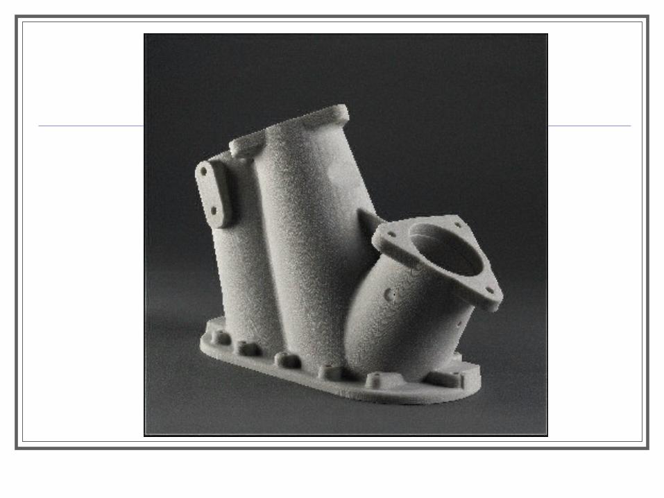
Selective Laser Sintering (SLS)Selective Laser Sintering (SLS)

SLS Video http://www.acucast.com/multimedia
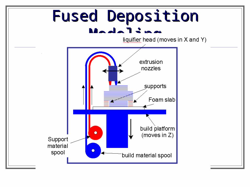
Fused Deposition ModelingFused Deposition Modeling
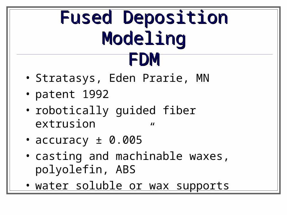
• Stratasys, Eden Prarie, MN• patent 1992• robotically guided fiber extrusion• accuracy ± 0.005”• casting and machinable waxes, polyolefin,
ABS• water soluble or wax supports
Fused Deposition ModelingFused Deposition ModelingFDMFDM


FDM material

Solid Ground Curing
http://home.att.net/~castleisland/sgc.htm

Solid Ground Curing (SGC) Devleoped by Cubital Ltd. of Israel High capital and operational cost Large heavy equipment Good dimensional accuaracy

SGC (from Efunda)
http://www.efunda.com/processes/rapid_prototyping/sgc.cfm

Instead of using a laser to expose and harden photopolymer element by element within a layer as is done in stereolithography, SGC uses a mask to expose the entire object layer at once with a burst of intense UV light. The method of generating the masks is based on electrophotography (xerography). This is a two cycle process having a mask generation cycle and a layer fabrication cycle. It takes about 2 minutes to complete all operations to make a layer:
1. First the object under construction (A) is given a coating of photopolymer resin as it passes the resin applicator station (B) on its way to the exposure cell (C).
2. A mask is generated by electrostatically transferring toner in the required object cross sectional image pattern to a glass plate (D) An electron gun writes a charge pattern on the plate which is developed with toner. The glass plate then moves to the exposure cell where it is positioned above the object under construction.
3. A shutter is opened allowing the exposure light to pass through the mask and quickly cure the photopolymer layer in the required pattern. Because the light is so intense the layer is fully cured and no secondary curing operation is necessary as is the case with stereolithography.
http://home.att.net/~castleisland/sgc.htm

4. The mask and object under fabrication then part company. The glass mask is cleaned of toner and discharged. A new mask is electrophotographically generated on the plate to repeat the cycle.
5. The object moves to the aerodynamic wiper (E) where any resin that wasn't hardened is vacuumed off and discarded.
6. It then passes under a wax applicator (F) where the voids created by the removal of the unhardened resin are filled with wax. The wax is hardened by moving the object to the cooling station (G) where a cold plate is pressed against it.
7. The final step involves running the object under the milling head (H). Both the wax and photopolymer are milled to a uniform thickness and the cycle is repeated until the object is completely formed within a wax matrix.
Secondary operations are required to remove the wax. It can either be melted away or dissolved using a dish-washing-like machine. The object is then sanded or otherwise finished as is done in stereolithography. The wax matrix makes it unnecessary to generate extra support structures for overhangs or undercuts. This, and the large volume capacity of the system, also makes it easy to nest many different objects within the build volume for high throughput.
http://home.att.net/~castleisland/sgc.htm

3D Printing3D Printing

Inkjets
http://home.att.net/~castleisland/sgc.htm
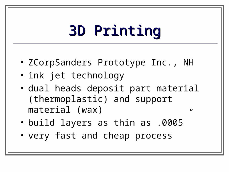
• ZCorpSanders Prototype Inc., NH• ink jet technology• dual heads deposit part material
(thermoplastic) and support material (wax)• build layers as thin as .0005”• very fast and cheap process
3D Printing3D Printing


Laser Engineered Net Shaping TM
http://home.att.net/~castleisland/sgc.htm

Laser Engineered Net Shaping TM
In development (Sandia Labs, Optomec) Fully Dense Metal parts with good
metallurgical properties Laser melts metal powder Powder delivered coaxially with laser Inert gas protects weld pool Near net shape with some finish machining
http://home.att.net/~castleisland/sgc.htm
http://www.xpress3d.com/