Rapid Printed Tooling for High-rate Production of ......Rapid Printed Tooling for High-rate...
5
Rapid Printed Tooling for High-rate Production of Microstructured Surfaces Marisely De Jesús Vega, Liezl Wee Sit, John Shearer, Joey Mead, Carol Barry Center for High-rate Nanomanufacturing, University of Massachusetts Lowell, Lowell, MA ABSTRACT Low cost production of microfluidic devices through injection molding, nanoimprint lithography or hot embossing requires fast and low cost production of tooling. Printing and sintering metal pastes was investigated as a novel approach for the rapid fabrication of metal tooling with microstructured surfaces. Paste composition and printing conditions were evaluated as controls for the size and quality of the surface features. Tooling has been produced from several metals and current work is focused on creating submicron-sized features. Then tooling performance and durability was assessed using injection molding, the steel microfeatures were undamaged after more than 5000 cycles. Keywords: metal printing, tooling, microinjection molding, microchannels 1 INTRODUCTION Devices with micro and nanostructured surfaces offer advantages such as small reagent volumes and shorter reaction times for applications in the medical industry and smaller and more effective devices in the electronics industry. Some applications in the medical industry include microneedles and microfluidic channels used for molecular analysis and identification of pathogens and toxins. Applications in the electronics industry include microelectronics and optoelectronics. The market for microfluidic devices is expected to grow to $5.2 billion by 2018 [1]. The high demand for these devices requires high volume and low cost manufacturing. Leading processes for the production of these devices are hot embossing, injection molding and injection compression molding. These processes, however, require development of tooling. The metal tooling preferred for injection molding of microfluidic devices can be produced using subtractive and additive manufacturing methods. In subtractive methods excess material is removed from the starting “block” of material until the desired geometries are obtained. Common subtractive techniques used to manufacture tooling are micromachining and lithography. In contrast, additive manufacturing techniques fuse layers of material to build the required shape. Some additive techniques include stereolithography, selective laser sintering, fused deposition and selective layer melting. The features sizes and limitations for these techniques are summarized in Table 1. Subtractive Manufacturing Micromachining [2-5] - Size: 5 μm or greater - Difficulty machining projections - Tool wear affects accuracy - Surface deformation as material layer exposed to heat - Grain size of metal affects smaller surfaces Lithography [6-8] - Size: 0.2 to 0.5 μm - Difficult to form drafts - Undercutting - Surface deformation - Limited available materials Additive Manufacturing Stereolithography [9-10] - Size: 20 μm or greater - Rough Surface - Photosensitive resins (limited materials and material degradation) Selective Laser Sintering [10-11] - Size: 20 μm or greater - Metal powder porosity issues - Slow heating/cooling of metal powder - Surface deformation due to uncontrolled thermal effects Fused Deposition [12] - Size: 50 μm - Limited feed stock shape - Limited resolution - Need precise temperature control Selective Layer Melting - Few studies available [12] Table 1. Tooling manufacturing techniques. In general, subtractive manufacturing techniques are limited by the inability to produce complex 60 TechConnect Briefs 2015, TechConnect.org, ISBN 978-1-4987-4730-1
Transcript of Rapid Printed Tooling for High-rate Production of ......Rapid Printed Tooling for High-rate...

Rapid Printed Tooling for High-rate Production of Microstructured Surfaces
Marisely De Jesús Vega, Liezl Wee Sit, John Shearer, Joey Mead, Carol Barry
Center for High-rate Nanomanufacturing, University of Massachusetts Lowell, Lowell, MA
ABSTRACT
Low cost production of microfluidic devices
through injection molding, nanoimprint lithography
or hot embossing requires fast and low cost
production of tooling. Printing and sintering metal
pastes was investigated as a novel approach for the
rapid fabrication of metal tooling with
microstructured surfaces. Paste composition and
printing conditions were evaluated as controls for the
size and quality of the surface features. Tooling has
been produced from several metals and current work
is focused on creating submicron-sized features.
Then tooling performance and durability was
assessed using injection molding, the steel
microfeatures were undamaged after more than 5000
cycles.
Keywords: metal printing, tooling, microinjection
molding, microchannels
1 INTRODUCTION
Devices with micro and nanostructured surfaces
offer advantages such as small reagent volumes and
shorter reaction times for applications in the medical
industry and smaller and more effective devices in
the electronics industry. Some applications in the
medical industry include microneedles and
microfluidic channels used for molecular analysis
and identification of pathogens and toxins.
Applications in the electronics industry include
microelectronics and optoelectronics. The market for
microfluidic devices is expected to grow to $5.2
billion by 2018 [1]. The high demand for these
devices requires high volume and low cost
manufacturing. Leading processes for the production
of these devices are hot embossing, injection molding
and injection compression molding. These processes,
however, require development of tooling.
The metal tooling preferred for injection molding
of microfluidic devices can be produced using
subtractive and additive manufacturing methods. In
subtractive methods excess material is removed from
the starting “block” of material until the desired
geometries are obtained. Common subtractive
techniques used to manufacture tooling are
micromachining and lithography. In contrast,
additive manufacturing techniques fuse layers of
material to build the required shape. Some additive
techniques include stereolithography, selective laser
sintering, fused deposition and selective layer
melting. The features sizes and limitations for these
techniques are summarized in Table 1.
Subtractive Manufacturing
Mic
rom
ach
inin
g
[2-5
]
- Size: 5 µm or greater
- Difficulty machining projections
- Tool wear affects accuracy
- Surface deformation as material layer
exposed to heat
- Grain size of metal affects smaller
surfaces
Lit
hog
raph
y
[6-8
]
- Size: 0.2 to 0.5 µm
- Difficult to form drafts
- Undercutting
- Surface deformation
- Limited available materials
Additive Manufacturing
Ste
reo
lith
og
rap
hy
[9-1
0]
- Size: 20 µm or greater
- Rough Surface
- Photosensitive resins (limited materials
and material degradation)
Sel
ecti
ve
Las
er
Sin
teri
ng
[1
0-1
1]
- Size: 20 µm or greater
- Metal powder porosity issues
- Slow heating/cooling of metal powder
- Surface deformation due to
uncontrolled thermal effects
Fu
sed
Dep
osi
tion
[12
]
- Size: 50 µm
- Limited feed stock shape
- Limited resolution
- Need precise temperature control
Selective Layer Melting - Few studies available [12]
Table 1. Tooling manufacturing techniques.
In general, subtractive manufacturing techniques
are limited by the inability to produce complex
60 TechConnect Briefs 2015, TechConnect.org, ISBN 978-1-4987-4730-1
geometries while current additive manufacturing For
the custom paste the effect of binder was studied with
a tip diameter and gap of 330 µm and a printing
speed of 1.75 mm/s.
techniques lack resolution [13].
This project investigates a novel additive
manufacturing process for the fast and low cost
production of metal tooling consisting of micro and
submicron features. The features are printed with a
metal paste in a single run, thus eliminating the layer
or step effect (resolution problems) present in
existing additive manufacturing techniques.
2 EXPERIMENTAL
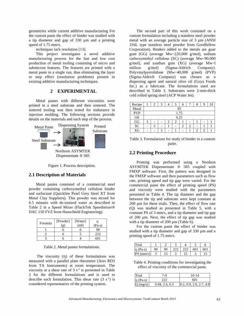
Metal pastes with different viscosities were
printed in a steel substrate and then sintered. The
sintered tooling was then tested for endurance in
injection molding. The following sections provide
details on the materials and each step of the process.
Figure 1. Process description.
2.1 Description of Materials
Metal pastes consisted of a commercial steel
powder containing carboxymethyl cellulose binder
and surfactant (Quickfire Pearl Grey Steel XT from
Metal Clay Suppliers). This powder was mixed for
6.5 minutes with de-ionized water as described in
Table 2 in a Speed Mixer (FlackTek Speedmixer®
DAC 150 FVZ from Hauschield Engineering).
Formula [Powder]
(g)
[Water]
(ml)
(Pa-s)
1 6 6 90
2 6 5 222
3 6 4 601
Table 2. Metal pastes formulations.
The viscosity () of these formulations was
measured with a parallel plate rheometer (Ares RD3
from TA Instruments) at room temperature. The
viscosity at a shear rate of 3 s-1 is presented in Table
2 for the different formulations and is used to
describe each formulation. This shear rate (3 s-1) is
considered representative of the printing system.
The second part of this work consisted on a
custom formulation including a stainless steel powder
metal with an average particle size of 3 µm (ANSI
316L type stainless steel powder from Goodfellow
Corporation). Binders added to the metals are guar
gum (GG) (average Mw~220,000 g/mol), sodium
carboxymethyl cellulose (SC) (average Mw~90,000
g/mol), and xanthan gum (XG) (average Mw~l
million g/mol) (Sigma-Aldrich Company).
Polyvinylpyrrolidone (Mw~40,000 g/mol) (PVP)
(Sigma-Aldrich Company) was chosen as a
dispersing agent and natural olive oil (Goya Foods
Inc.) as a lubricant. The formulations used are
described in Table 3. Substrates were 2-mm-thick
cold rolled spring steel (ACP Water Jet).
Recipe 1 2 3 4 5 6 7 8 9 10
Metal 95
PVP 1.75
Oil 0.25
GG 3 - - 2 2 1 - 1 - 1
SC - 3 - 1 - 2 2 - 1 1
XG - - 3 - 1 - 1 2 2 1
Table 3. Formulations for study of binder in a custom
paste.
2.2 Printing Procedure
Printing was performed using a Nordson
ASYMTEK Dispensemate ® 585 coupled with
FMXP software. First, the pattern was designed in
the FMXP software and then parameters such as flow
rate, printing speed and tip gap were varied. For the
commercial paste the effect of printing speed (PS)
and viscosity were studied with the parameters
presented in Table 4. The tip diameter and the gap
between the tip and substrate were kept constant at
200 µm for these trials. Then, the effect of flow rate
(Q) was studied as presented in Table 5, with a
constant PS of 3 mm/s, and a tip diameter and tip gap
of 200 µm. Next, the effect of tip gap was studied
with a tip diameter of 200 µm (Table 6).
For the custom paste the effect of binder was
studied with a tip diameter and gap of 330 µm and a
printing speed of 1.75 mm/s.
Trial 1 2 3 4 5 6
(Pa-s) 90 90 222 222 601 601
PS (mm/s) 3 15 3 15 3 15
Table 4. Printing conditions for investigating the
effect of viscosity of the commercial paste.
Trial 7-9 10-14
(Pa-s) 222 601
Q (mg/s) 0.94, 2.6, 6.5 0.2, 0.9, 2.0, 2.7, 4.9
Printed
Substrate
Metal Paste
Steel Substrate
Dispensing System
Nordsom ASYMTEK Dispensemate ® 585
61Advanced Manufacturing, Electronics and Microsystems: TechConnect Briefs 2015

Table 5. Printing conditions for investigating the
effect of flow rate of the commercial paste.
Trial 15-19 20-23
(Pa-s) 601 601
PS (mm/s) 0.5 3
Q (mg/s) 0.9 2.7
TG (µm) 250, 300, 400, 500 300, 400, 500, 600
Table 6. Printing conditions for investigating the
effect of tip gap with the commercial paste.
After printing the green tooling was heated for
debinding and sintering. The debinding step removed
the binder while the sintering step fused the particles
together and provided adhesion of the metal particles
to the substrate. The optimum debinding and
sintering conditions are summarized in Table 7.
Step Temperature (°C) Time (min)
Debinding 572 30
Cooling Room Temperature Varied
Sintering 976 120
Table 7. Post-printing processes.
2.3 Injection Molding
The tooling was tested for endurance by
molding using a three-ton microinjection molding
machine (Nissei, type: AU3E) with a two stage
injection unit. The tooling produced are inserted in
the B-plate of the mold using a steel cartridge to hold
it in place and a PTFE sheet was placed next to the
tooling to provide thermal insulation.
Material used for injection molding is
polystyrene. Processing conditions were optimized
and are summarized in Table 8. Up to 5000 parts
were produced.
Melt Temperature (°C) 275
Mold Temperature (°C) 70
Injection Velocity (mm/s) 140
V/P Switchover Pressure (MPa) 65
Pack Pressure (MPa) 100
Pack Time (s) 3
Table 8. Injection molding conditions.
2.4 Characterization
Overall surface appearance was investigated
using an optical microscope (Zeiss), whereas line
height and width were measured using a contact
profilometry (Dektak, model: Veeco 500).
2. RESULTS AND DISCUSSION
Higher viscosity pastes accompanied by lower
speeds provided better replication of pattern with less
spreading of the paste on the substrate and no voids
(Figure 2).
(a)
(b)
(c)
(d)
(e)
(f)
Figure 2. Effect of viscosity and speed using
commercial paste: (a-c) speed of 3 mm/s (Trials 1, 3
and 5) and (d-f) speed of 15 mm/s (Trials 2, 4 and 6).
The effect of flow rate on width and height is
presented on Figure 3. The line width increased at a
linear rate of 282.5 µm/(mg/s) for the 222 Pa-s paste
and 206.0 µm/(mg/s) for the 601 Pa-s paste. The line
height, however, did not show any significant change
for any of the pastes. Minimum feature width was
427 µm and 551 µm for 601 Pa-s and 222 Pa-s,
respectively.
Figure 3. Effect of flow rate for pastes with viscosity
of 222 and 601 Pa-s.
The effect of tip gap was found to be dependent
on the flow rate. At low flow rate (0.9mg/s) feature
dimensions were constant, whereas at high flow rate
(2.6 mg/s) line width and height increased linearly at
a rate of 4.7 µm/µm and 0.3 µm/µm, respectively
(see Figure 4).
These results show that parameters such as paste
viscosity, flow rate and tip gap control the
dimensions of the printed patterns. However, this
paste presents problems with porosity -i.e particle
distribution differs from line edge to center of line
0
200
400
0
1000
2000
3000
0.0 2.0 4.0 6.0 8.0H
eig
ht
(µm
)
Wid
th (
µm
)
Flow Rate (mg/s)
601 Pa-s (Width)
222 Pa-s (Width)
601 Pa-s (Height)
222 Pa-s (Height)
62 TechConnect Briefs 2015, TechConnect.org, ISBN 978-1-4987-4730-1

(Figure 5). This porosity issue cannot be fixed with
the processing conditions or sintering step, for this
reason, a custom paste was investigated.
Figure 4. Effect of tip gap when printing with
different flow rates.
(a)
(b)
(c)
(d)
Figure 5. Images of (a-b) green stage and (c-d)
sintered stage.
The effect of viscosity when a custom paste was
used is presented in Figure 6. The combination of
three binders (GG, SC and XG) in equal amounts
produced the best results with a viscosity of 25 Pa-s
(Figure 6i).
(a)
(b)
(c)
(d)
(e)
(f)
(g)
(h)
(i)
Figure 6. Effect of custom formulation on printed
features for viscosities of: (a-c) <10 Pa-s, (d-f) 13-16
Pa-s, (g-i) 22-26 Pa-s.
Endurance was tested. Tooling was not deformed
after 5000 cycles in the injection molding machine
and parts were produced with 100% replication
(tooling/feature height/depth were approximately 150
μm) (Figure 7).
Figure 7. Replication and endurance test.
3. CONCLUSIONS
This work investigated printing parameters
as a control of feature size and a custom paste as a
control of uniformity and porosity of microchannels.
Tooling endured for 5000 injection molding cycles,
thus representing a great potential as tooling for
microfluidic devices.
4. ACKNOLEDGEMENT
National Science Foundation and Nissei
America, Inc.
5. REFERENCES
[1] "Microfluidic Device Market Forecast to Reach
$5.7B by 2018." Researchmarket, 4 Sept. 2013
[2] Shanhan, J. "Trends in Micro Machining
Technologies." N.p., n.d
[3] Rajurkar, K.P. Us-KoreaWorkshop on
Miniaturization Technologies. USA, Sept. 2004.
[4] Nguyen, M.D. et al, Precision Engineering 37
(2013):399-407
[5] Lui, Y. et al, Proceedings of the 16th Inernational
Sysmposium on Electromachining, 2010
[6] Benevides, G. M4: Workshop on Micro/Meso-
Mechanical Manufacturing, May 2000
[7] Pease, F., and S. Chou. Proceeding of the IEEE,
Feb. 2008
[8] Wang, Q. et al, Microelectronics Journal 40
(2009): 149-155.
[9] Aditya, K. "SLA and SLS." N.p., n.d.
[10] "Rapid Tooling Open Doors to Die Casting."
North America Diecasting Association, 2009
[11] "What Is Stereolithography?" TechFAQ What Is
Stereolithography Comments. N.p., 27 July 2013
[12] Vaezi, M. et al, "A review on 3D micro-additive
manufacturing technologies" (2013)
0
100
200
300
400
500
0
500
1000
1500
2000
2500
0 200 400 600
Hei
gh
t (µ
m)
Wid
th (
µm
)
Tip Gap (µm)
0.9 mg/s (Height)2.6 mg/s (Width)0.9 mg/s (Width)2.6 mg/s (Width)
0
100
200
0 2000 4000Hei
gh
t (µ
m)
Injection Molding Cycles
63Advanced Manufacturing, Electronics and Microsystems: TechConnect Briefs 2015

[13] "Additive vs Subtractive Manufacturing: Which
is Right for You?" American Precision
Prototyping, LLC, 9 June 2014
[14] Kumbhani, M. Ph.D. Dissertation. . University of
Massachusetts Lowell, December, 2013.
64 TechConnect Briefs 2015, TechConnect.org, ISBN 978-1-4987-4730-1