Changes of State Melting Freezing Vaporization Condensation.

.
UCRL- JC-120708 L-19169-2 PREPRINT
Rapid Mold Replication
Glenn M. Heestand Richard G. Beeler, Jr.
Donald L. Brown Tom Meier
Thomas A. Shepp Lawrence Livermore National Laboratory
Livermore, CA
James T. Feeley Laser Fare, Inc. Smithfield, RI
This paper was prepared for submittal to The 27th International SAMPE Technical Conference
Albuquerque, New Mexico October 9 - October 12,1995
June 1995
Thisis a preprint of a paper intended for publicationin a journal orproceedings. Since changes may be made before publication, this preprint is made available with the understanding that it will not be cited orreproduced without the permission of the author.
MASTER

DISCLAIMER
This document was prepared as an account of work sponsored by an agency of the United States Government. Neither the United States Government nor the University of California nor any of their employees, makes any warranty, express or implied, or assumes any legal liability or responsibility for the accuracy, completeness, or useful- ness of any information, apparatus, product, or process disclosed, or represents that its use would not infringe privately owned rights. Reference herein to any specific commercial products, process, or service by trade name, trademark, manufacturer, or otherwise, does not necessarily constitute or imply its endorsement, recommendation, or favoring by the United States Government or the University of California. The views and opinions of authors expressed herein do not necessarily state or reflect those of the United States Government or the University of California, and shall not be used for advertising or product endorsement purposes.

RAPID MOLD REPLICATION
Glenn M. Heestand, Richard G. Beeler Jr., Donald L. Brown, Tom Meier, and Thomas A. Shepp
Lawrence Livermore National Laboratory
Livermore, California 94551 and
James T. Feeley Laser Fare, Inc.
1 Industrial Drive South, Lan-Rex Industrial Park Smithfield, Rhode Island 02917
P.O. BOX 808, L-460
ABSTRACT
The desire to reduce tooling costs have driven manufacturers to investigate new manufacturing methods and materials. In the plastics injection molding industry replicating molds to meet production needs is time consuming (up to 6 months) and costly in terms of lost business. We have recently completed a feasibility study demonstrating the capability of high rate Electron Beam Physical Vapor Deposition (EBPVD) in producing mold inserts in days, not months. In the current practice a graphite mandrel, in the shape of the insert's negative image, was exposed to ajet of metal vapor atoms emanating from an electron beam heated source of an aluminum-bronze alloy. The condensation rate of the metal atoms on the mandrel was sufficient to allow the deposit to grow at over 30 p / m i n or 1.2 mils per minute. The vaporization process continued for approximately 14 hours after which the mandrel and deposit were removed from the EBPVD vacuum chamber. The mandrel and condensate were easily separated resulting in a fully dense aluminum-bronze mold insert about 2.5 cm or one inch thick. This mold was subsequently cleaned and drilled for water cooling passages and mounted on a fixture for operation in an actual injection molding machine. Results of the mold's operation were extremely successful showing great promise for this technique. This paper describes the EBPVD feasibility demonstration in more detail and discusses future development work needed to bring this technique into practice.
KEY WORDS: Physical Vapor Deposition, Tooling, Injection Molding
1. INTRODUCTION
The plastics injection molding industry has a need for a more cost effective method for the production and replication of injection mold inserts. Current production methods combine conventional machine shop techniques with the extensive use of Electron Discharge . ' Machining (ED,M). Mold materials are typically tool steel and the inserts are ordinarily machined from material which is in the hardened state, hence the extensive use of the EDM
process. The production of a set of mold inserts for a modestly complex set of parts can require many months of machine shop time which could represent significant dollars of lost production.
Recently Lawrence Livermore National Laboratory (LLNL) along with Laser Fare of Narragansett, RI initiated the development of a process using Electron Beam Physical Vapor Deposition (EBPVD) for making mold inserts. In this process a mandrel, in the shape of the object to be made, is exposed to a vapor jet of condensing metal atoms emanating from a source heated by an electron beam. Condensation rates on surfaces nomial to the vapor jet are -30 pm/min. which is sufficient to deposit a one inch coating in 14 hours. Mandrel material to date has been restricted to graphite because of its good high temperature properties and ease of machining. Both aluminum-bronze alloy and P20 tool steel have vaporized. At this point several molds have been made up to a thickness of 2.5 cm with one of them being successfully operated in an actual injection molding machine.
Although the feasibility of this process has been shown there are many technical issues to overcome. These include material strength and hardness, dimensional stability, ability to reproduce complex shapes and the development of a technology to fabricate mandrels suitable for an EBPVD process. A more detailed description of the process, current status of the technical issues and future development plans will be discussed.
2. EXPERIMENTAL DESCRIPTION
Figure 1 shows a schematic of the electron beam vaporizer used in this process. The mandrel to be coated is placed approximately 50 cm above the vapor source and is enclosed in a thermal package. This package, which consists of insulation, shielding and heaters, is used to control the substrate temperature both prior and during the coating process. The electron beam is incident from the left in Figure 1 and is bent onto the melt (material to be vaporized) surface by a local magnetic field (magnet pole faces not shown). Beam powers in this process are on the order of 100 kW. A water cooled copper crucible is used to contain the melt. The feeder on the right replenishes the melt as material is vaporized. A water cooled copper enclosure contains the unused portion of the vapor and prevents it from accumulating on the stainless steel vessel walls. Operating pressures for this process are below 10-2 Pa.
Figure 2 is an actual photograph of the apparatus. In this case the mandrel (located at the center of the picture) is graphite in the shape of a waffle iron approximately 8 cm on a side. The thermal package surrounding the mandrel is evident. The large plate at the bottom of the page is a magnetic pole face which provides the magnetic field used to bend the electron beam onto the melt. The waffle iron mandrel was used initially to do a proof-of-principal but was never tested in an injection molding machine.
. .

Vacuum Vessel
Figure 1. Schematic of vaporizer used for building mold inserts.
The intense electron beam from the left is focused to spot on the melt and this spot is swept over the melt surface to generate a line source. The local high average power density (-104 W/cm2,) is sufficient to vaporize the melt material. The vaporized material forms a jet of metal vapor atoms which is highly directional. F0r.a 50 cm standoff, the area perpendicular to :A&,*, -,.- the vapor flow, over which the the vapor flux varies by less than lo%, is bounded by a circle . 9.5 cm in radius. A larger standoff yields a more even distribution over a given area but requires a larger vessel and a longer coating times or higher evaporation rates to achieve a given thickness.
’
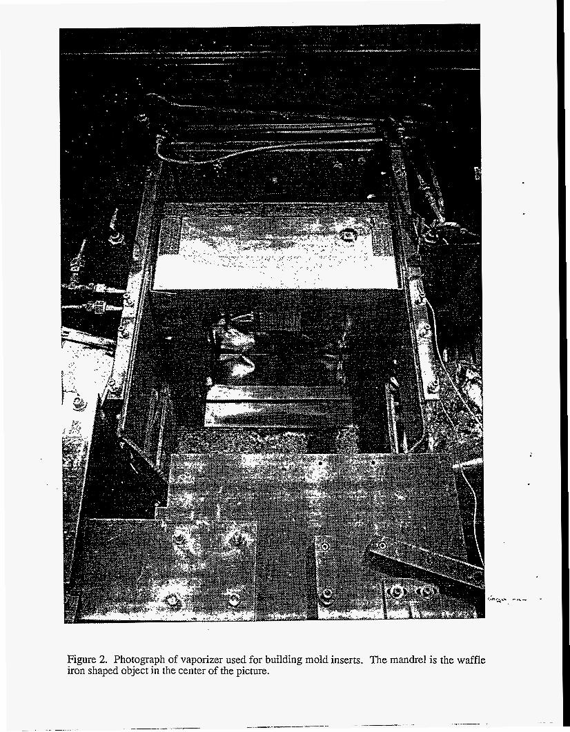
Figure 2. Photograph of vaporizer used for building mold inserts. The mandrel is the waffle iron shaped object in the center of the picture.

In the initial vaporization runs an aluminum-bronze alloy (C6300) was used as the evaporant. This is a good alloy for vaporization because the dominant constituents, A1 and Cu, have fairly high vapor pressures which are comparable. This means that the condensate stoichiometry should be close to that of the material being fed into the melt. It is difficult to maintain stoichiometry for alloys which have constituents with widely disparate vapor pressures. In general the low vapor pressure components tend to remain behind in the melt.
According to Movchan (1) one needs to operate the mandrel at temperatures which are on the order of half the melting temperature of the alloy being vaporized in order to achieve full density. During this project evidence was obtained that at high evaporation rates one must run closer to the alloy melting point than was suggested by Movchan's early work. For the aluminum-bronze runs the mandrel was preheated to 1123 K and maintained at that temperature throughout the vaporization process. This is - 85% of the melting point but was necessary to obtain good condensate microstructure and full density.
Following the preheating of the mandrel the electron beam gun was turned on and slowly brought up to full power (-100 kw) and held there over a 14 hour period. At this power the evaporation rate for the alloy was -5 kg/h. At a 50 cm standoff this produces a vapor density of -3.5~1013 atoms/cm3 which is sufficient to achieve a coating rate of 30pm/min. The duration of the run was sufficient to provided a total condensate thickness of 2.5 cm.
During the run the melt was fed at 5 kg/h to keep melt inventory constant. The feeder mechanism consisted of a motor driven push rod system which pushed cylindricavfeed bars to the melt edge where radiant heat and the skip electron beam would melt the alloy causing it to drip into the melt. The feeder was replenished using a vacuum load locking mechanism.
Very often in high power electron beam vaporizers one observes spitting or the ejection of macroparticles from the melt surface. This often results from trapped gas bubbles within the melt which travel towards the surface and then explode. This can greatly effect coating uniformity and microstructure in an adverse way. Fortunately, in these runs very little spitting was observed except near the end of a feed bar. At this point the bar can no longer support itself within the feed tube so it falls into the melt as a chunk causing some spitting. For long feed bars this can be kept to a minimum.
After the vaporization was completed the vessel was allowed to cool over night under vacuum. The next day the vessel was opened and the mandrel and deposit were removed. Since a thin layer of boron nitride was applied to the mandrel as a parting agent the mandrel and condensate were fairly easily separated. However, in some places small portions of the graphite mandrel were removed with the condensate so that the mandrel was not reusable. Following its removal from the mandrel the mold insert was given a light polishing to remove any adhered graphite, drilled for water cooling passages and mounted on a block for use in an injection molding machine.
In some cases P20 tool steel was substituted for the aluminum-bronze alloy as the evaporant. The same procedure was followed but the results slightly different. In.the case of aluminum- bronze the main Constituents have similar vapor pressures whereas in P20 there are some low vapor pressure elements, such as molybdenum and carbon,which don't readily evaporate. Consequently, what is deposited is P20 tool steel without its low vapor pressure components. This point will be further discussed.
3. RESULTS
Figure 3 shows the cavity side of an aluminum-bronze mold used to produce the torso of a toy soldier. The core side, not shown, was made from P20 tool steel. The core-cavity set were run in an injection molding machine to produce 5000 of the plastic components shown. After the run the mold insert was removed and inspected for wear. Very little wear was shown indicating that the inserts would be capable of producing thousands of more parts.

In the EBPVD process atoms are layed down on the mandrel atom by atom not in globules as in metal spray processes. Consequently, this process is capable of picking up minute details with a very high quality surface finish. For the torso molds produced by EBPVD the surface finish required only a light buffing to remove any excess graphite which didn't cleanly separate. Because of this, the graphite mandrels used to date haven't been reusable. Use of a cleaner parting agent and/or different mandrel material may alleviate this.
Dimensional stability and maintaining specific tolerances are very important in producing mold inserts. In this process one must be aware of the differences in thermal expansion and elastic modulus between the mandrel and mold when cooling down from the deposition temperature to room temperature. For the case of aluminum-bronze on graphite, the actual mold (-8 cm in linear dimension) shrunk 0.8 mm with respect to the mandrel on cooling down from 1123 K to room temperature. This shrinkage can be taken into account when machining the mandrel or reduced by choosing material pairs with similar thermal expansion coefficients or reducing the deposition temperature. Flatness of the core-cavity pair for this exercise was good to within & 0.05 mm.
The vapor jet emanating from the melt is highly supersonic meaning that the forward velocity of the atoms is larger than their random thermal speeds. For the vaporizer used at LLNL it is estimated that the mach number is close to 7 meaning that the forward motion is seven times as large as any sideways or lateral motion. Therefore, coating by EBPVD is a line-of-sight process.
Figure 4 shows modeling results for coating a slot 1 cm deep by 1 cm in width for mach numbers of 7 and 2. Vapor is incident from the top and is assumed to coat to a depth of 1 cm. As can be seen the coating on vertical surfaces is thin compared with that on perpendicular surfaces. This results from the vapor flow being mostly parallel to the vertical surfaces. The situation is less exacerbated for the lower mach number case. In addition, because of this phenomena, this process will not coat undercuts. Consequently, there are some limitations to the applicability of this process especially to complex shaped components. More development work is planned in this area and will be discussed in the next section.
*
1
Figure 3. Photograph of aluminum-bronze mold insert (cavity side) and the plastic part it was used to make.
;,a

0.44 mm-
1.20 mm+
1 I I I
I I I I
01 I $
r I I I I I I I I
- Condensate
nm.
- Substrate
IO mm.
Figure 4. Schematic of how a 10 mm by 10 mm slot would coat using an EBPVD process. Vapor flow is incident from the top. The solid line represents a flow with a mach number of 7 while the dashed line represents a mach number of 2.
The aluminum bronze material vaporized and deposited during this mold replication experiment is an alloy of copper having 10 wt. percent aluminum and fractional percentages of iron and nickel. For 10 wt. percent AI-Cu alloy, the bcc (p) single phase is stable above 1123 K , indicated by AI-Cu phase diagram in Figure 5 (2).
The time-temperature-trmsformation "TIT" diagram for this A1-Cu alloy, shown in Figure 6, is in many ways analogous to that of alloys in the Fe-C system in that the martensitic (a+p') and bainite (a+p1) microstructures found in this system resemble those encountered in steels (3-5). Solution heating of the aluminum bronze mold mass to (1 123 K - 1283 K) for greater than 3 hours achieves a homogeneous (p) solid solution within the mold mass. As in heat treatment practices for steel, the quench rate effect on moderating bulk diffusional processes determines the final microstructure and corresponding material properties of the mold mass. Referring to Figure 6, a low cooling rate (CR3) produces a soft, coarse, fully annealed bainite- like (a+p1) microstructure having maximum ductility. A high cooling rate (He) produces a..,..&,: ~.~ - fine martensite (a+p') structure having high hardness and strength. Intermediate cooling rates and subsequent tempering heat treatments can be used to optimize the material for ductility and toughness.
The microstructure of as-deposited aluminum bronze material is shown in Figure 7 (sample 529-1 1 at 200X). During vapor deposition, this material was held above 1123 K in vacuum for greater than 14 hours; then allowed to slowly cool under vacuum at an average rate of 30 K/min. This micrograph shows large light colored (a) grains in a darker retained (pi) matrix.

The microstructure of the same material, after 3 hours of solution heat treatment at 1073 K followed by water quench, is shown in Figure 8 (sample 530-14 at 250X). This micrograph shows a fine (a+p') martensitic structure produced by transformation of (pi) to (3') during the rapid cooling (30 Us) of this mold material. Figure 9 shows Vickers (DPH) hardness measurements taken across the polished as-deposited sample 529. This material had a nominal hardness of 180 DPH, consistent with intermediate (CR1) cooling rates for this composition material. DPH hardness roughly translates to a Brinell 180 hardness or Rockwell "B" 89 hardness using ANSVASTM E 140-78 guidelines
Figure 10 show same scale Vickers (DPH) hardness measurements taken across the polished solution heat treat and water quenched sample 530. This material measured a nominal hardness of 325 DPH, consistent with water quench cooling rates and martensite formation. This DPH hardness roughly translates to a Brinnell310 hardness or Rockwell "C" 32, using the same guidelines. The mold insert shown in Figure 3 and used in an injection molding machine did not have the benefit of a heat treat process. As was previously mentioned some inserts were made by vaporizing P20 tool steel. P20 contains mostly Fe with small percentages of Mn, Si, Cry Mo and C. Iron vaporizes readily in vacuum near 2250 K (vapor pressure -395 Pa). At this temperature the vapor pressures of Mn, Si and Cr are between 53 and 5.3~104 Pa and should also vaporize. However, under identical conditions Mo and C have vapor pressures of 2.6~10-3 Pa and 1.3~10-3 Pa respectively. Consequently one would not expect to find these latter two elements in the
(6).
45
22 24 26 2
50
Figure 5. Phase diagram for aluminum-bronze. (Reprinted by permission from ASM International.)

? I ,
Time, seconds
Figure 6. Time-temperature-transformation "TIT'" for aluminum-bronze. (Reprinted by
I
Figure 7. Microstructure of as deposited aluminum-bronze.

Figure 8, Microstructure of same material as in Figure 7 after a 3 hour heat treatment at 1073 K followed by a water quench.
'I 150 -
100-
"1 920529
Measurements taken approximately 0.5 mm. apart
Figure 9. Vickers (DPH) hardness measurements taken across the thickness of the polished as-deposited sample whose micrograph is shown in Figure 7.

i .
Y&lJJJlJ
I
Hardness takm at .OS mm apart I s 1 Figure 10. Vickers (DPH) hardness measurements taken after the heat treat and water quench. This figure corresponds to the micrograph in Figure 8.
4. FUTURE WORK
At the time of this writing LLNL was finalizing a CRADA with the National Center for Manufacturing Sciences (NCMS) to continue development on this project over the next three years. The tasks of this CRADA center around the issues discussed in the previous section.
Controlling dimensional stability is one of the most important development tasks in this project. Finding combinations of mandrel materials and evaporants which have similar thermal expansion coefficients will greatly improve this situation. Another approach is to operate the mandrel at a lower temperature. This helps in two ways. It minimizes the total expansion and opens up the possibility of using mandrel materials which couldn't otherwise be considered. Using plasma assisted vapor deposition with a biased substrate has been shown (7) to allow one to run at considerably lower substrate temperatures. In this process ions, which are naturally present in the vapor, are accelerated to the substrate with an energy equal to the mandrel bias voltage (few hundred electron volts). This energy is deposited in the condensate providing extra energy to enable atoms to migrate and fill voids and establish full density. Running a discharge coincident with the vaporization process increases the ion density in the vapor and makes the process more effective.
Additional materials besides aluminum-bronze and P20 can be vaporized if strength and hardness need to be increased. Maraging steels have a hardness of -54 on the Rockwell C scale as compared to 28-37 for P20. In addition the yield strength of maraging steels is close to 290 ksi as compared to 126 ksi for P20. Maraging steels have. the additional advantages of being easier to vaporize and maintain stoichiometry than P20. Most of the dominant components of maraging steels (Fey Ni, Co and Ti) have vapor pressures which are well within a factor of 100 of each other. This means covaporization is fairly straightforward. Xhe -., - low vapor pressure component, molybdenum, can be vaporized in a dual source system illustrated in Figure 11. In this system the elements of comparable vapor pressures are in one crucible while the low vapor pressure component or components are located in an adjacent crucible. The electron beam is time shared between the two crucibles in such a way that the vaporization rate from each crucible is appropriate to produce the correct stoichiometry on the mandrel. Everything else in this process is the same as pictured in Figure 1. To produce a maraging steel requires a heat treat process. The effect of a heat treat process on a mold insert, in terms of dimensional stability, must also be investigated.

There are two potential techniques for improving the vapor deposition on vertical surfaces. The first is to use a substrate manipulator to rotate the mandrel so that vertical surfaces are less vertical and more likely to pick up condensate. The second technique vaporizes into a background gas. Collisions between the gas and the upwardly moving vapor jet tend to scatter the atoms in the jet reducing their effective mach number. According to Figure 4 this should even out the deposition on all surfaces.
Finally the last area of concern is mandrel development. Graphite has been used to date because of its good vacuum and high temperature properties. Although graphite is easy to machine it is messy and its thermal expansion coefficient is considerably lower than most metals. An alternative would be to use castable ceramics which can be made into various shapes using rapid prototyping techniques. Whatever material is used must have good high vacuum characteristics (low outgas3ng rates). Castable ceramics, along with other possible candidates, will be evaluated with the goal of producing high quality low cost mandrels consistent with EBPVD.
I
Vapor J e t s
// Wate r Cooled Copper P a r t i t i o n
W a t e r Cooled Copper C r u d b
Low Vapor Pressure Components
l e
Figure 11. Schematic of dual source vaporization which is used in the vaporization of alloys whose components have a wide range of vapor pressures.
5. CONCLUSIONS
The feasibility of using EBPVD for making mold inserts which are capable of producing thousands of plastic parts in injection molding machines has been demonstrated. Although the combination of graphite mandrels and an aluminum-bronze condensate was very successful there are other combinations which could better meet industry needs. These new combinations, along with techniques to improve mandrel fabrication and operational scenarios to operate the mandrel at lower temperatures, will be explored in the next phase of this project. -,r j ,.. .- ., -
6. ACKNOWLEDGEMENTS
This work was perfomed under the auspices of the U.S. Department of Energy by Lawrence Livermore National Laboratory under contract No. W-7405-Eng-48.

7. REFERENCES
1. B.A. Movchan and A.V. Demchisin, Fizika Metall, 28.653 (1969).
2. Metals Handbook, 8th edition, Vol8, American Society for Metals, Metals Park, OH, p. 259.
3. C. Brooks, Heat Treatment, Structure and Properties of Nonferrous Alloys. American Society for Metals, 1982, pp. 311-321.
4. Metals Handbook, 9th edition, Vol2, American Society for Metals, Metals Park, OH, p. 259.
5. Jellison and Klier, Trans. of AIME, 233,1965, pp. 1694-1702.
6. Annual ASTM Standards, 10,1978, pp. 307-311.
7. R.F. Bunshah in R.F. Bunshah, ed., Handbook of Deposition Technologies for Films and Coatings, Noyes Publications, Park Ridge, NJ, 1994, p. 210.
ST 95-091/GMH:dlb
i .
.