Rapid Analysis of Silicate, Carbonate, and Phosphate Rocks ...
88
Rapid Analysis of Silicate, Carbonate, and Phosphate Rocks- Revised Edition GEOLOGICAL SURVEY BULLETIN 1401
-
Upload
truonghanh -
Category
Documents
-
view
224 -
download
1
Transcript of Rapid Analysis of Silicate, Carbonate, and Phosphate Rocks ...

Rapid Analysis of Silicate, Carbonate, and Phosphate RocksRevised Edition
GEOLOGICAL SURVEY BULLETIN 1401


Rapid Analysis of Silicate, Carbonate, and Phosphate RocksRevised Edition
By LEONARD SHAPIRO
GEOLOGICAL SURVEY BULLETIN 1401
UNITED STATES GOVERNMENT PRINTING OFFICE, WASHINGTON 1975
UNITED STATES DEPARTMENT OF THE INTERIOR
CECIL D. ANDRUS, Secretary
GEOLOGICAL SURVEY
W. A. Radlinski, Acting Director
First printing 1975 Second printing 1978
For sale by the Branch of Distribution, U.S. Geological Survey, 1200 South Eads Street, Arlington, VA 22202
CONTENTS
Page
Abstract -------------------------------------------------------- 1 Introduction ---------------------------------------------------- 1 Apparatus and instruments --------------------------------------- 4
Teflon beakers ---------------------------------------------- 4 Water-repellent coated pipets ---------------------------------- 5 Stopcock-pipet device ---------------------------------------- 6 Tilting pipet ------------------------------------------------ 6 Squeeze pipet ------------------------------------------------ 8 High-precision piston pipet ----------------------------------- 8 Pipetting machine ------------------------------------------- 9 One-litre water dispenser ------------------------------------ 10 Fusion equipment -------------------------~------------------ 11 Multiple magnetic stirrers ------------------------------------ 11 Sequential heating device for FeO ---------------------------- 11 Carbon dioxide scanning test tube ------------------------------ 12 Middle-range carbonate tube ---------------------------------- 13 Evolution-absorption apparatus for C02 ---------------------- 13 Manual spectrophotometer _ __ _ _ _ _ __ _ _ __ _ _ _ _ _ _ __ __ ___ _ _ _ ___ _ _ _ _ 13
Automated spectrophotometer -------------------------------- 16 Automated atomic absorption equipment ------------------------ 21
Automatic sample changer -------------------------------- 22 Preparation of powdered samples ---------------------------------- 25 Two-solution procedure ------------------------------------------ 25
Preparation of solution A ------------------------------------ 25 Preparation of solution B ------------------------------------ 27 Determination of constituents ---------------------------------- 29
Si02 in silicate, carbonate. and phosphate rocks______________ 29
Al20a in silicate and carbonate rocks ----------------------- 30 Al20a in phosphate rocks -------------------------------- 32 Total iron in silicate, carbonate, and phosphate rocks -------- 32 Ti02 in silicate, carbonate, and phosphate rocks -------------- 34 MnO in silicate, carbonate, and phosphate rocks ------------- 35 Pz05 in silicate rocks ------------------------------------- 37 Pz05 in carbonate rocks ---------------------------------- 38 P205 in phosphate rocks ---------------------------------- 38 MgO, N azO, and K20 in silicate, carbonate, and phosphate
rocks and CaO in silicate rocks -------------------------- 39 Total CaO+MgO in carbonate and phosphate rocks ---------- 40
Single-solution procedure _________________________________ _,__ _ __ _ __ 43
Preparation of solution -------------------------------------- 43 Determination of constituents ------------------------------..,.- 46
Si02 in silicate, carbonate, and phosphate rocks -------------- 46
III
IV CONTENTS
Page
Single-solution procedure-Continued Determination of constituents-Continued
Al20a in silicate, carbonate, and phosphate rocks ----------- 47 Total iron in silicate, carbonate, and phosphate rocks -------- 47 Ti02 in silicate, carbonate, and phosphate rocks -------------- 48 MnO in silicate, carbonate, and phosphate rocks ------------ 49 P20s in silicate and carbonate rocks ------------------------ 50 P20s in phosphate rocks ---------------------------------- 51 MgO, N~O, and K20 ·in silicate, carbonate, and phosphate
rocks and CaO in silicate rocks -------------------------- 53 Total CaO+MgO in carbonate and phosphate rocks ---------- 54
Determinations on separate samples -------------------------------- 54 H20 in silicate, carbonate, and phosphate rocks ------------------ 54 FeO in silicate, carbonate, and phosphate rocks ------------------ 57 C02 in silicate rocks ------------------------------------------ 58
Rapid scanning technique for low levels of C02 -------------- 59 Technique for C02 content above 0.1 percent ---------------- 60
C02 in carbonate rocks by evolution ---------------------------- 62 C02 in phosphate rocks- -----------·--------------------------- 64 C02 in limestone and dolomite by titration ---------------------- 64 F in silicate, carbonate, and phosphate rocks -------------------- 66 S in silicate, carbonate, and phosphate rocks -------------------- 68 Sulfate S in silicate, carbonate, and phosphate rocks ------------ 70 Powder density ---------------------------------------------- 71 Bulk density ------------------------------------------------ 73
References cited ------------------------------------------------- 74
ILLUSTRATIONS
Page
FIGURE 1. Schematic diagram of a complete rock analysis -------- 3 2-11. Diagrams showing:
2. Teflon beaker and cover ---------------------- 5 3. Stopcock pipet device ------------------------ 7 4. Tilting pipet -------------------------------- 8 5. Squeeze pipet --------------------,----------- 9 6. One-litre dispenser -------------------------- 10 7. Sequential heater for FeO -------------------- 12 8. C02 scanning test tube ----------------------- 13 9. Middle-range carbonate tube _____ ------------- 14
10. Evolution-absorption apparatus for C02 -------- 15 11. Cell and cell adapter for the spectrophotometer _ 16
12. Photograph showing automated spectrophotometer as-
sembly ------------------------------------------- 18 13-16. Diagrams showing:
13. Schematic sketch of dipper arm and shifter mechanism of sample changer -------------- 20
14. Schematic sketch of pin drive of Geneva mechanism __________________________ - _ _ _ _ 23
15. Tube in position for water determination -------- 56 16. C02 tube in heating block -------------------- 62

CONTENTS v TABLES
Page
TABLE 1. Conversion of percent transmission ( T) to absorbance (A) -- 17 2. Heavy-liquid mixtures ---------------------------------- 71
Any use of trade names and trademarks in this publication is for descriptive purposes only and does not constitute endorsement
by the U.S. Geological Survey.

RAPID ANALYSIS OF SILICATE, CARBONATE, AND PHOSPHATE ROCKS
REVISED EDITION
By LEONARD SHAPIRO
ABSTRACT
The rapid methods previously used by the U.S. Geological Survey to determine the major constituents of rocks have been modified to introduce atomic absorption spectrometry (AAS) where applicable. Two procedures are available for determining 10 constituents: one, from a single solution prepared by a nitric-acid dissolution of a lithium metaborate-lithium tetraborate fusion, and the other, a two-solution method in which one portion of sample is dissolved in an HF-H2SO,-HNOa mixture and another portion is fused with NaOH. In both techniques, Si02, Al20a, F~Oa, Ti02, P20s, and MnO are determined spectrophotometrically, and CaO, MgO, Na20, and K20 are determined by AAS. Separate portions of samples are used for the following determinations: FeO by titration with K2Cr201 after decomposition with HF and H2SO,; total H20 by its weight when evolved on heating a mixture of sample plus flux; H20 by loss of weight at 110° overnight; C02 by its volume upon evolution with acid; fluorine by a new indirect measurement of Si02 evolved with fluorine on heating; and. sulfur by a new procedure based on a turbidimetric measurement of BaSO, after an aqua regia attack. Several mechanical aids and automated devices are used for the analyses.
INTRODUCTION
The methods described here are those currently in use by the U.S. Geological Survey for rapid rock ana.lysi·s. They are an outgrowth of the scheme of analysis originally presented in 1952 (Shapiro and Brannock, 1952), revised in 1956 (Shapiro and Brannock, 1956) and again revi'Sed in 1962 (Shapiro and Brannock, 1962). Since 1962 approximately 2,500 samples per year have been analyzed. During the last few years atomic absorption spectrometry ( AAS) techniques have been introduced into the procedure to replace the disodium ethylenediamine tetra-acetate (EDTA) automatic titration of GaO and MgO and the flame photometric determination of Na20 and K20. During this time a single-solution procedure, based on fusion with a lithium metaborate-tetraborate mixture, was developed for which the
1
2 ANALYSIS OF SILICATE, CARBONATE, PHOSPHATE ROCKS
same 10 constituents are determined as in the two-solution procedure. This report provides a detailed description of both the single- and two-solution methods as both are actually used in the laboratory. Some chemists currently using the two-solution procedure may prefer to continue to do so, with the modifications described. Others :may prefer the single-solution procedure which is somewhat faster, being capable of providing a sample solution in two hours. However, because it is based on the use of a 200-mg sample, the sampling error of the single-solution method may be larger than that of the two-solution method, which requires 500 mg of sample.
In the presence of much fluorine, as is common in phosphate rocks, separate provision is made in the two-solution procedure for the removal of fluorine, which would interfere in the determination of aluminum. This is not required in the single-solution method.
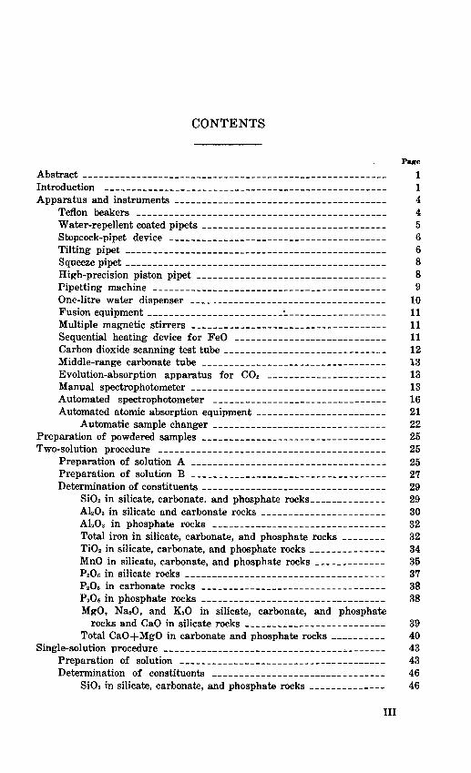
Methods are described for the determination of Si02, Al203, total iron, FeO, MgO, CaO, Ti02, MnO, P20i'i, K20, Na20, H20+, H20-, C02, F, and S. The complete scheme for the rapid analysis of rocks is shown in a flow diagram in figure 1. In the U.S. Geological Survey the methods described are generally applied to 50-to 100-sample batches in order to benefit from the advantages of automation and mechanization.
To be acceptable the methods must give results which sum to 100±1 percent. The methods are designed so that major constituents, those 10 percent or above, a,re expected to be accurate to 1 percent of the amount present; these are reported to the nearest 0.1 percent. Constituents between 1 and 10 percent are also reported to the nearest 0.1 percent but are accurate to ± 0.1 percent absolute. Below 1 percent, results are reported to 0.01 percent and are accurate to ± 0.02 percent absolute. These accuracies have been confirmed by comparing the results of these methods with those obtained by careful conventional analysis and by the use of primary and secondary standards. The collaborative study of the accuracy and precision of conventional analysis (Fairbairn and others, 1951), which provided the incentive for the development of rapid procedures, and the followup study (Stevens and others, 1960) both provide guidelines for accuracy and precision that we are well able to meet.
The methods for preparing solutions of samples are adequate for all but a few rare refractory rock types. In some cases very refractory silicates can be dissolved by HF decomposition in sealed vessels under heat and pressure (May and Rowe, 1965;
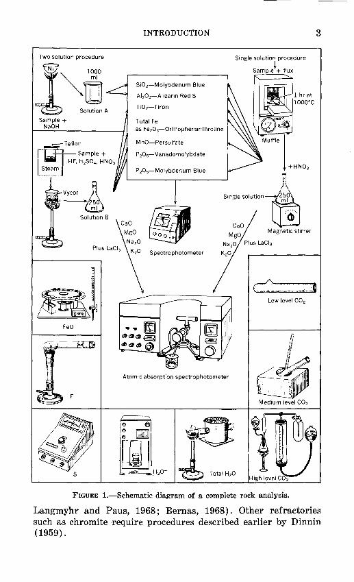
Two solution procedure
l "" . 1000 ~ ml
[] Solution A
Sample+ NaOH
~Teflon
I liJitl ___ Sample +
'~~·I HF,H2S04.HN03
E~
--c:~ Vycor &· '· 1 -50.
ml
Solution B
INTRODUCTION
Si02-Molybdenum Blue
AI 20 3-Aiizarin RedS
Ti02- Tiron
Total Fe as Fe20 3-0rthophenanthroline
MnO-Persulfate
P20 5-Vanadomolybdate
Muffle l 1 hr at 1000°C
+HN03
Smgle >oloUon--+ ..
LnJ Magnetic stirrer
Spectrophotometer
Low level C0 2
Atomic absorption spectrophotometer
Medium level C02
FIGURE !.-Schematic diagram of a complete rock analysis.
3
Langmyhr and Paus, 1968; Bernas, 1968). Other refractories such as chromite require procedures described earlier by Dinnin (1959).

4 ANALYSIS OF SILICATE, CARBONATE, PHOSPHATE ROCKS
The methods for determining ferrous iron and water are of limited applicability in the presence of significant amounts of organic matter, such as may be found in phosphate and carbonate rocks and shales.
The procedure for determination of sulfur is not suitable for glassy rocks such as obsidian. It also fails to detect sulfur in samples containing more than 0.5 percent Ba. In addition, a few rare sulfur minerals are not attacked by aqua regia. Where organic matter is present the sulfur often is not brought into solution and the sulfur determination can be expected to be in error by approximately 0.01 percent S per percent organic matter.
APPARATUS AND INSTRUMENTS
In addition to the commonplace items such as beakers, pipets, and so forth, the following specialized equipment is used: Teflon beakers, water-repellent coated pip·ets, a spectrophotometer, an automated spectrophotometer, a 1-1 water dispenser, atomic absorption spectrometric equipment, a carbon dioxide scanning test tube, a middle-range carbonate tube, evolution-absorption apparatus for C02, stopcock pipets, a pipetting machine, tilting pipets, squeeze pipets, high-precision piston pipets, fusion equipment, multiple m·agnetic stirrers, and a sequential heating device for FeO. Automatic sample changers attachable to both the atomic absorption apparatus and the spectrophotometer are useful but not essential.
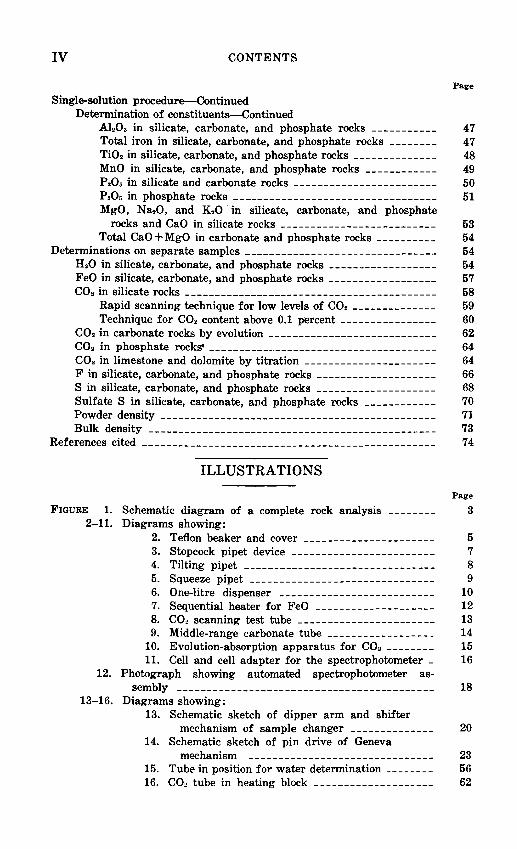
TEFLON BEAKERS
Teflon beakers are used in the preparation of solution B. In recent years, Teflon beakers of various sizes and shapes have become readily available, and they may be adapted to the procedure described. It is better, however, to use beakers specifically designed for the purpose. Such beakers may be made from Teflon bar stock and the covers from sheet Teflon (Shapiro, 1959).
Teflon is unaffected by acids ·at steam-bath temperatures, but, unlike platinum, it conducts heat poorly. To assure adequate heating for the decomposition of powdered samples, a beaker with a tightly fitting cover was designed which could be heated on the sides as well as the bottom by the stea.m of a steam bath (fig. 2). The beakers are suspended through holes 46 mm in diameter in a sheet of polypropylene, which is used to replace the top of a steam bath.

APPARATUS AND INSTRUMENTS
I I lj_
t::::;:=======~;:::=:::::::l• 3 m m
I• 40 mm ---~~~ t r+- 50mm : ~1___1
6mm
1.5 mm
Beaker
I I I I I I I
47 mm
I I__L I I
~------! __ -~ ~3mm
FIGURE 2.-Teflon beaker and cover.
WATER-REPELLENT COATED PIPETS
5
The use of water-repellent coated pipets saves time. Rinsing between samples is eliminated because coated pipets retain only negligible quantities of liquid. With a coated pipet, aliquots from 30 samples can be easily taken in about 7 min. The precision of this operation is comparable to that using conventional pipets, but as the volume delivered is slightly altered, it may be necessary to pipet both the samples and the standard with the same pipet, or to use pipets known to deliver practically equal volumes of solution. Using a 10 ml pipet, a delivery rate of about 10 sec may be obtained by enlarging the orifice by cutting and fire-polishing the tip. Such rapid flow does not affect the reproducibility of the volume delivered by a coated pipet.

6 ANALYSIS OF SILICATE, CARBONATE, PHOSPHATE ROCKS
The pipet is coated with water repellent according to the directions of the manufacturer. Dimethyl dichlorosilane is a repellent that is very convenient to use, as it need be only passed through a clean pipet, which is then allowed to dry.
STOPCOCK PIPET DEVICE
The reproducibility of 8-·ml pipets is generally within 0.5 percent of the volume. If the concentration of the constituent to be determined is high, as for example Si02 in silicate rocks, greater pipetting reproducibility is· desirable. With the stopcock-pipet device illustrated in figure 3, sample portions can be taken with a precision of about 0.1 percent.
The device consists of a two-way stopcock fused to a waterrepellent 8-ml pipet in .such a way that the volume of liquid delivered by the pipet, after it has been filled to the stopcock, is nearly 8 mi. On . one arm opposite the pipet, a 150-ml flask is fitted with a squeeze bulb and valve to provide for overflow and suction. Another squeeze bulb, with a small hole or a valve in it, is attached to the other arm.
The stopcock-pipet is used in the following manner: With the stopcock in a position so that all openings are closed, the bulb attached to the overflow flask is squeezed to force air from the exhaust valve. The pipet is inserted into the liquid to be pipetted, and the stopcock is rotated so that the passage from the pipet to the overflow flask is open. The liquid rises to fill the pipet and then overflows past the stopcock. When the liquid begins to pass the stopcock, the stopcock is closed. The tip of the pipet is wiped with a tissue and placed over the receiving vessel. The stopcock is rotated to allow air to enter through the hole or valve in the bulb on the other arm of the stopcock and to allow the liquid to drain from the pipet. When the flow has stopped, a finger is placed over the hole in the bulb and the bulb is squeezed to force out the drop of liquid remaining in the tip. The process is repeated for the next solution.
The pipet is self-rinsing in that it is coated with a water repellent and the overflow of the next liquid carries the slight residual liquid over into the overflow flask.
TILTING PIPET
Many manual types of dispensing devices are useful for transferring a solution into a series of receiving vessels; one which is used in this laboratory is the tilting pipet shown in figure 4. It is much slower than the pipetting machine but is particularly useful

APPARATUS AND INSTRUMENTS
D
FIGURE 3.-Stopcock pipet device. A, overflow flask; B, exhaust valve; C, squeeze bulbs; D, air-inlet hole.
7

8 ANALYSIS OF SILICATE, CARBONATE, PHOSPHATE ROCKS
'I:, ,,,, !Ill :t,,
.~/:',: .!·,. .. ·:
s11 ii
•
,;tJJJ!!t~l!iii,\,i~§li!!i'~~!lli\:~~~f} FIGURE 4.-Tilting pipet.
when only a few solutions are involved. These dispensers are available in a range of capacities and are cheap enough that they can be used to store and dispense many reagents.
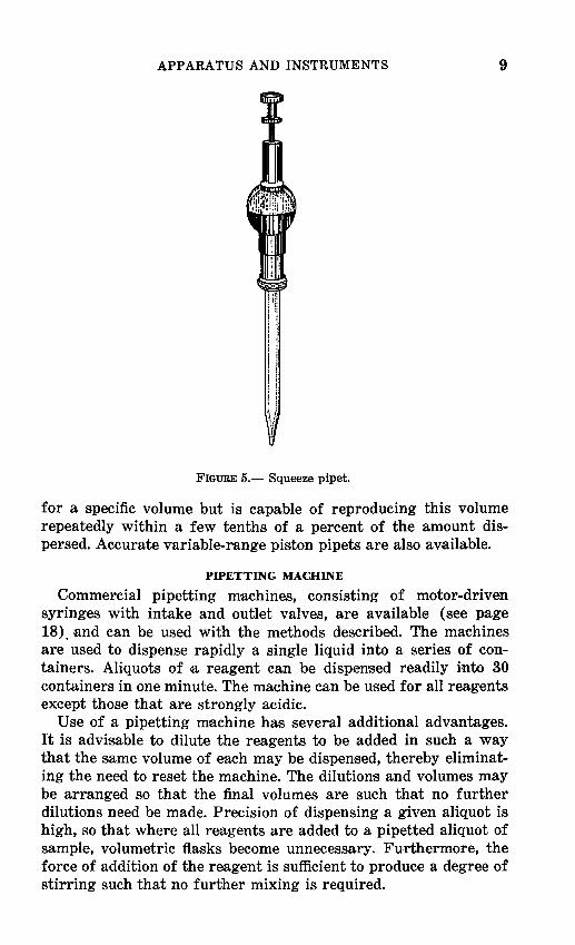
SQUEEZE PIPET
Squeeze pipets (fig. 5) have a rubber bulb into which the upper end of the glass pipet is inserted. The bulb is squeezed by a plunger activated by finger pressure. Adjustable mechanical limit stops allow a fixed displacement of the plunger so that the uptake of liquid upon removal of the finger is reproducible. Commonly these devices can be used with one percent reproducibility for measurements up to about 5 mi.
HIGH-PRECISION PISTON PIPET
In recent years high-precision piston pipets have become available for small volumes from 0.001-1.000 mi. Each pipet is made
APPARATUS AND INSTRUMENTS 9
FIGURE 5.- Squeeze pipet.
for a specific volume but is capable of reproducing this volume repeatedly within a few tenths of a percent of the amount dispersed. Accurate variable-range piston pipets are also available.
PIPETTING MACHINE
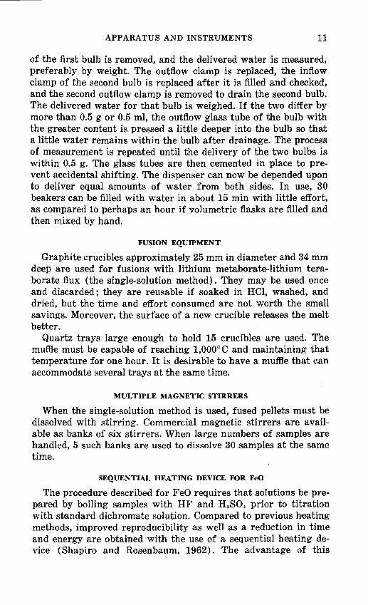
Commercial pipetting machines, consisting of motor-driven syringes with intake and outlet valves, are available (see page 18). and can be used with the methods described. The machines are used to dispense rapidly a single liquid into a series of containers. Aliquots of a reagent can be dispensed readily into 30 containers in one minute. The machine can be used for all reagents except those that are strongly acidic.
Use of a pipetting machine has several additional advantages. It is advisable to dilute the reagents to be added in such a way that the same volume of each may be dispensed, thereby eliminating the need to reset the machine. The dilutions and volumes may be arranged so that the final volumes are such that no further dilutions need be made. Precision of dispensing a given aliquot is high, so that where all reagents are added to a pipetted aliquot of sample, volumetric flasks become unnecessary. Furthermore, the force of addition of the reagent is sufficient to produce a degree of stirring such that no further mixing is required.

10 ANALYSIS OF SILICATE, CARBONATE, PHOSPHATE ROCKS
ONE-LITRE WATER DISPENSER
One-litre solutions of solution A must be prepared. If many solutions of this volume are to be prepared at one time, the physieal effort of measuring into a volumetric flask and mixing by inversion can be considerable. The required quantity of water can be measured automatically and dispensed easily with the 1-1 water dispenser shown in figure 6. The dis·penser is made from two 1-1 leveling bulbs, two check VJalves, two overflow bulbs, and interconnecting tubing controlled by four pinch clamps. To speed the rate of inflow and outflow, the interconnecting tubing is of the widest diameter that can be used with the available glassware. In setting up the device, the glass outflow tubes are first positioned flush with the inside surface of the rubber stopper, and the two bulbs are allowed to be filled one at a time by removing one of the inflow clamps until the water is checked by the check valve. The inflow clamp is replaced, and the other inflow clamp is removed allowing the other bulb to be filled. Meanwhile the outflow clamp
Float valves
To sink
Plast1c beakers
FIGURE 6.-0ne-litre dispenser.
APPARATUS AND INSTRUMENTS 11
of the first bulb is removed, and the delivered water is measured, preferably by weight. The outflow clamp is replaced, the inflow clamp of the second bulb is replaced after it is filled ,and checked, and the second outflow clamp is removed to drain the second bulb. The delivered water for that bulb is weighed. If the two differ by more than 0.5 g or 0.5 ml, the outflow glass tube of the bulb with the greater content is pressed a little deeper into the bulb so that a little water remains within the bulb after drainage. The process of measurement is repeated until the delivery of the two bulbs is within 0.5 g. The glass tubes are then cemented in place to prevent accidental shifting. The dispenser can now be depended upon to deliver equal amounts of water from both sides. In use, 30 beakers can be filled with water in about 15 min with little effort, as compared to perhaps an hour if volumetric flasks are filled and then mixed by hand.
FUSION EQUIPMENT
Graphite crucibles approximately 25 mm in diameter and 34 mm deep are used for fusions with lithium metaborate-lithium teraborate flux (the single-solution method). They may be used once and discarded; they are reusable if soaked in HCl, washed, and dried, but the time and effort consumed a~re not worth the small savings. Moreover, the surface of a new crucible relea;ses the melt better.
Quartz trays large enough to hold 15 crucibles are used. The muffle must be capable of reaching 1,000°C and maintaining that temperature for one hour. It is desirable to have a muffle that can accommodate several trays at the same time.
MULTIPLE MAGNETIC STIRRERS
When the single-solution method is used, fused pellets must be dissolved with stirring. Commercial magnetic stirrers are available as banks of six stirrers. When large numbers of samples are handled, 5 such banks are us·ed to dissolve 30 samples at the same time.
SEQUENTIAL HEATING DEVICE FOR FeO
The procedure described for FeO requires that solutions be prepared by boiling samples with HF and H2S0-1 prior to titration with standard dichromate solution. Compared to previous heating methods, improved reproducibility as well as a reduction in ti.me and energy are obtained with the use of a sequential heating device (Shapiro and Rosenbaum, 1962). The advantage of this
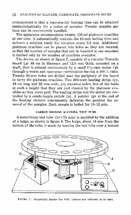
12 ANALYSIS OF SILICATE, CARBONATE, PHOSPHATE ROCKS
arrangement is that a reproducible heating time can be obtained semiautomatically for a series of samples. Twenty samples per hour can be conveniently handled.
The apparatus accommodates twenty 100-ml platinum crucibles at one time. It automatically controls the 10-min boiling time and delivers a solution ready for titration every 3.5 min. Additional platinum crucibles can be placed into holes as they are vacated, so that the number of samples that can be handled in one sequence is limited only by the number of crucibles available.
The device, as shown in figure 7, consists of a circular Transite board (A) 48 em in diameter and 12.5 mm thick, mounted on a shaft, that is rotated continuously by a small 1lj:!-rpm motor (B) through a worm and spur-gear combination having a 100:1 ratio. Twenty 50-mm holes are drilled near the periphery of the board to carry the platinum crucibles. Two 200-watt heating strips (c), 18 em long and 32 mm wide, are mounted below five of the holes at such a height that they are just cleared by the platinum crucibles as they move past. The heating strips and the motor are controlled by a single-toggle switch (D). A pointer (E) at the end of the heating element conveniently indicates the position for removal of the samples. Each sample is boiled for 10-12 min.
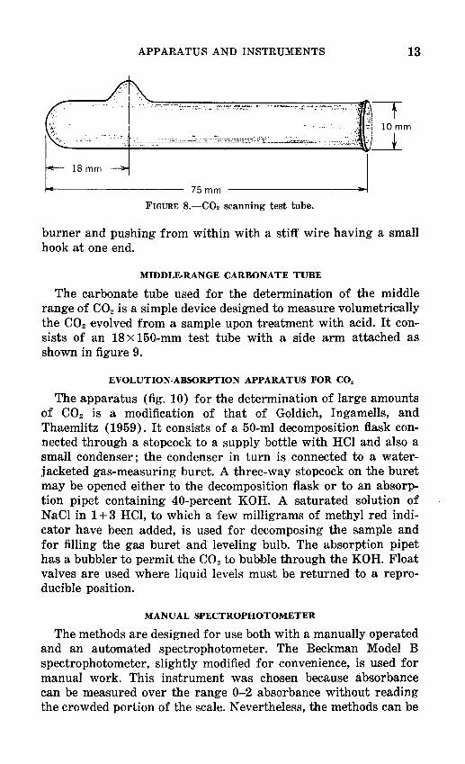
CARBON DIOXIDE SCANNING TEST TUBE
A borosilicate test tube (10x75 mm) is modified by the addition of a bulge, as shown in figure 8. The bulge, about 18 mm from the bottom of the tube, is made by heating the test tube over a bunsen
FIGURE 7.-Sequential heater for FeO. Letters are referred to in text.
APPARATUS AND INSTRUMENTS 13
18 mm
75 mm -----+-~J FIGURE 8.-C02 scanning test tube.
burner and pushing from within with a stiff wire having a small hook at one end.
MIDDLE-RANGE CARBONATE TUBE
The carbonate tube used for the determination of the middle range of C02 is a sim:ple device designed to measure volumetrically the C02 evolved from a sample upon treatment with acid. It consists of an 18 x 150-mm test tube with a side arm attached as shown in figure 9.
EVOLUTION-ABSORPTION APPARATUS FOR CO:~
The apparatus (fig. 10) for the determination of large amounts of C02 is a modification of that of Goldich, Ingamells, and Thaemlitz (1959). It consists of a 50-ml decomposition flask connected through a .stopcock to a supply bottle with HCl and also a small condenser; the condenser in turn is connected to a waterjacketed gas-measuring buret. A three-way stopcock on the buret may be opened either to the decomposition flask or to an absorption pipet containing 40-percent KOH. A saturated solution of NaCl in 1 + 3 HCl, to which a few milligrams of methyl red indicator have been added, is used for decomposing the sample and for filling the gas buret and leveling bulb. The absorption pipet has a bubbler to permit the C02 to bubble through the KOH. Float valves are used where liquid levels must be returned to a reproducible position.
MANUAL SPECTROPHOTOMETER
The methods are designed for use both with a manually operated and an automated spectrophotometer. The Beckman Model B spectrophotometer, slightly modified for convenience, is used for manual work. This instrument was chosen because .absorbance can be measured over the range 0-2 absorbance without reading the crowded portion of the scale. Nevertheless, the methods can be

14 ANALYSIS OF SILICATE, CARBONATE, PHOSPHATE ROCKS
OD Test tube 18 X 150 mm
I
FIGURE 9.-Middle-range carbonate tube.
adapted readily to other spectrophotometers. Only one phototube is used for the measurements required in our procedures, all of which are made in the range 420-650 nm. The stability of the instrument is maintained by a voltage regulator in the 115-volt a-c line.
In place of a set of matched absorption tubes, a single fixed tube with a drain at the bottom generally was found to be more satisfactory. The simple adapter, shown in figure 11, was built to hold the absorption cell in a fixed position in the cell compartment. Care must be taken to insure that the adapter and cell compartment are rigidly fixed in order to maintain a constant light path. The absorption cell should be treated with a water repellent to eliminate the necessity of rinsing between additions of solutions. The spectrophotometer must be raised on a platform approximately 130 mm high to allow access to the absorption tube outlet.
Readings are taken from the percent transmittance scale, rather than from the absorbance scale, as the former is less subject to

APPARATUS AND INSTRUMENTS 15
A --
~-~ = "' II ,
FIGURE 10.-Evolution-absorption apparatus for C02. A, decomposition flask; B, gas buret; C, absorption pipet; D, leveling bulb; E, float valves; F, bubbler; G, HCl supply bottle.
reading error during routine day to day work because of the uniformity of this scale.
For those determinations for which the spectrophotometer is used, percent-transmittanc,e readings are first converted to absorbance by interpolation of the values in table 1, which was derived

16 ANALYSIS OF SILICATE, CARBONATE, PHOSPHATE ROCKS
'\ 1 mm brass
all joints butt-soldered
Pinch clamp or -'-=;o..;;::::~~~ efectrohosecock
...........__Face plate of spectrophotometer
FIGURE 11.-Cell and cell adapter for the spectrophotometer.
by the use of the equation, A (absorbance) =2- log T (transmittance). All calculations are made with absorbance values because they have a linear rather than logarithmic relationship to concentration, thus simplifying the calculations.
In recent years spectrophotometers have becom·e available which give a digital readout directly in concentration and which are equipped with flow-through tubes. Many such spectrophotometers are suitable replacements for the above described equipment.
AUTOMATED SPECTROPHOTOMETER
An automated spectrophotometer was assembled from commercially avaHable components and coupled with a sample changer designed and built in our laboratory (Shapiro and Massoni, 1972). The units comprising the entire assembly are: the spectrophotometer equipped with a flow-through cell; a digital converte·r; a printer; a pipetter; and ·a sample changer. The apparatus is shown in figure 12. It is possible to combine any spectrophotometer of

APPARATUS AND INSTRUMENTS 17
TABLE I.-Conversion of percent transmission (T) to absorbance (A)
T A T A T A T A -
30.0 0.523 50.0 0.301 70.0 0.155 90.0 0.046 30.5 . 516 50.5 .297 70.5 .152 90.5 .043 31.0 .509 51.0 .292 71.0 .149 91.0 .041 31.5 .502 51.5 .288 71.5 .146 91.5 .039 32.0 .495 52.0 .284 72. 0 .143 92.0 .036 32.5 .488 52.5 .280 72.5 .140 92.5 .034 33.0 .482 53.0 .276 73. 0 .137 93.0 .032 33.5 .475 53.5 .272 73. 5 .134 93.5 .029 34.0 .469 54.0 .268 74.0 .131 94.0 .027 34.5 .462 54.4 .264 74.5 .128 94.5 .025 35.0 .456 55.0 .260 75.0 .125 95.0 .022 35.5 .450 55.5 . 256 75.5 .122 95.5 .020 36.0 .444 56.0 .252 76. 0 .119 96.0 .018 36.5 .438 56.5 .248 76.5 .116 96.5 .016 37.0 .432 57.0 .244 77.0 .114 97.0 .013 37.5 .426 57.5 .240 77.5 .111 97.5 .011 38.0 .420 58.0 .237 78.0 .108 98.0 .009 38.5 • 415 58.5 .233 78. 5 .105 98.5 .em 39.0 .409 59.0 .229 79.0 .102 99.0 .004 39.5 .403 59.5 .226 79.5 .100 99.5 .002
40.0 .398 60.0 .222~ 80.0 .097 40.5 .393 60. 5 .218 80.5 .094 41.0 .387 61. 0 .215 81.0 .092 41.5 .382 61.5 .211 81.5 .089 42.(i .377 62. 0 .208 82.0 .086 42.5 .372 62.5 .204 82.5 .084 43.0 .367 63.0 .201 83.0 .081 43.5 .362 63. 5 .197 83.5 .078 44.0 . 357 64.0 .194 84.0 . 076 44.5 .352 64.5 .190 84.5 .073 45.0 .347 65.0 .187 85.0 .071 45.5 .342 65.5 .184 85.5 .068 46.0 .337 66.0 .180 86. 0 .066 46.5 .333 66.5 .177 86.5 .063 47.0 .328 67.0 .174 87.0 .060 47.5 .323 67.5 .171 87.5 .058 48.0 .319 68.0 .168 88. 0 .056 48.5 .314 68. 5 . 164 88.5 .053 49.0 .310 69.0 .161 89.0 .051 49.5 .305 69.5 .158 89.5 .049
good quality, one of several digital converters available from chemical supply house catalogues, •and any printer that can be coupled to the internal code of the digital converter out:put. Many problems are bypassed, however, if the three units are designed by the manufacturer to be used together; a number of companies make such combinations.
The spectrophotometer must be stable with no significant drift over a 15-min period. Moreover, the output of its photocurrent must be accessible to permit connection of a digital converter.
We selected the Beckman Model DB-G spectrophotometer 1 and associated converter and printer. The standard 1-cm sample cell is replaced by a commercial 1-cm flow-through cell fitted with s·mall glass inlet and outlet tubes at the top, to which plastic tubing is attached. The volume of the inlet side of the cell must be kept low to allow adequate flushin_g of one sB~mple by the next one. Therefore, 3-mm ID tubing not more than 30 em long is attached to the inlet glass tube, while broader gage tubing of any convenient size may be attached to the outlet side.
1 Beekman Instruments, Inc., 2500 Rubor Blvd., Fullerton, Ca!ifomia.

18 ANALYSIS OF SILICATE, CARBONATE, PHOSPHATE ROCKS
FIGURE 12.-Automated spectrophotometer assembly.
An electrically driven pipet provides the suction by which liquid is drawn from the sample beaker, through the flow-through tube and out to waste. Pipetters are available from several companies at reasonable cost. They generally consist of a motor-driven syringe with steel ball valves arranged so liquid can flow into the syringe during the downstroke of the syringe piston. Then on the upstroke, or discharge stroke, the steel ball valves prevent liquid from entering the inlet side but allow it to leave the exhaust side. We used the Filamatic Model AB 2 instrument, which we have modified by adding two cam-activated microswitches. The normally closed switch is in series with the pipetter motor and is positioned to stop the pipetter on the completion of one cycle. The normally open switch activates the printer and is positioned to close just prior to the completion of the pi petting cycle. The pipetter in turn is activated by a switch on the sample changer as the dipper arm approaches its lowest position. The rate of pipetting is 5 sec per cycle, and the preset volume is 25 mi.
Digital converters designed for spectrophotometers all perform the same functions. The photocurrent generated in a spectrophotometer is a logarithmic function of the concentration of an absorbing solution. The converter electronically changes this logarithmic relationship to a linear one and in addition provides
2 National Instrument Company, Baltimore, Maryland.

APPARATUS AND INSTRUMENTS 19
an amplifier so that the resultant voltage can be adjusted to read any desired value. It then performs an analog to digital conversion which can be read and (or) fed to a printer. With this device the reading for a blank solution can be set to zero, after which the device can be set to read the numerical concentration value for a standard solution. If the colored system being measured follows Beer's Law, as is the case in U.S. Geological Survey procedures, subsequent solutions will then be read and be printed directly in concentration units.
The sample chang·er is the only instrumental component completely designed and constructed at the U.S. Geological Survey. The changer is a modification of an earlier model (Shapiro and Massoni, 1968), which is described herein under the section called "Automated atomic absorption equipment." The same Geneva movement is used to drive and position the placement of each beaker, but the motor speed was changed from 1112 rpm to 4 rpm; the gear ratio allows 12 sec per sample rather than 45 sec.
The main changes are designed to accommodate more and larger beakers while reducing the dia.meter of the plexiglass carrier plate from a 91-cm disk to a 71-cm disk so the changer could fit on a standard table top. The three concentric circles each having 24 holes 50 mm in di~meter are spaced uniformly around the disk. The centers of the inner and outer holes are aligned on the same radii, and the centers of the holes of the middle circle are displaced halfway between each pair of radii. These holes are cut 11 mm deep into the carrier plate and are intended for 100-ml beakers. Holes 59 mm in diameter and 5.5 mm deep are cut at the same centers to accommodate 150-ml beakers. A switching arrangement is constructed for the dipper arm so that it can be autom·atically shifted from one row of holes to the next at the completion of a revolution. After the last beaker a final shift is used to activate a latching switch to turn the changer off (see figure 13).
The dipper arm, as seen in figure 13, carries a glass aspirator tube connected by a plastic tube to the inlet of the flow-through tube in the spectrophotometer. The arm pivots at one end, which is mounted on a rotatable shaft. Also mounted on the lower end of this shaft are three collars, each having a projecting peg and a slot 90° away from the peg. The three collars are positioned so that their pegs are offset from each other sufficiently so that a projecting metal shifter plate attached to the sample carrier plate will press against the upper peg as it passes but will miss the second peg, rotating the movable shaft and thereby shifting the dipper arm so that the glass aspiration tube is over the second row

20 ANALYSIS OF SILICATE, CARBONATE, PHOSPHATE ROCKS
Latching microswitch
spring detent
FIGURE 13.-Schematic sketch of dipper arm and shifter mechanism of sample changer.
of beakers. A spring detent pressing into a collar slit assures that the dipper arm movement is reproducible. After another full rotation of the carrier plate, the metal shifter plate now presses against the second peg and causes the dipper arm to shift so that the glass aspirator tube is over the third row of beakers. At the conclusion of the next full rotation, the shifter plate presses against the bottom peg causing a cam attached to the rotating shaft to press against a latching microswitch that disconnects the drive motor and stops the operation of the changer. The latching switch must be manually reset before the next cycle can be started. A pilot light connected across this switch serves as a reminder to push the reset button.
The dipper arm is raised and lowered by a cam lifter as in the earlier sample changer, but in addition a second cam on the same shaft is used to close a microswitch to activate the pipetter at the point where the dipper arm is at its lowest point. The sample changer has its own on-off switch.
APPARATUS AND INSTRUMENTS 21
The solutions to be measured are prepared in 100- or 150-ml beakers. The spectrophotometer is turned on to warm up, and blank solution is transferred to the reference cell, which is a standard 1-cm cell. If fewer than 72 solutions are to be analyzed, they are placed on the carrier plate with the last one in the last hole so that after the solutions are recorded the changer will be turned off automatically. The first beaker in the sequence contains a blank solution and the second a known standard. After all of the beakers are positioned on the carrier plate it is rotated by hand to place the first beaker under the dipper arm, which must be in the raised position during rotation. The switches for the spectrophotometer, the converter, and the pipetter must all be on and the spectropp.otometer set to the proper wavelength; the printer is off at this time. The reset button on the changer is pressed if the changer had shut itself off when last used. The toggle switch for the changer is switched on, causing the arm to lower, and in so doing activates the pipetter, which then transfers 25 ml of blank solution through the flow-through tube. When the dipper arm has moved to the rai,sed position. the toggle is pushed to the off position. The spectrophotometer is now adjusted manually to read 100 percent T, the digital converter is s:et to read concentration, and the zero adjustment is set so that the displayed number is 000. The toggle is then fli'Pped on, the table rotates, and the sequence repeats, transferring the known standard solution to the flowthrough tube. When the dipper arm is up again, the toggle is turned off and the concentration adjustment knob is adjusted manually until the displayed number corresponds to the value of the known standard. The printer and the toggle switch of the changer are switched on. All the subsequent solutions now are measured, and their concentrations printed automatically. A few beakers of water are run following the samples to rinse the pipetter. The entire measurement and printout procedures require approxi,mately ~5 min if the changer is loaded to capacity.
AUTOMATED ATOMIC ABSORPTION EQUIPMENT
Flame-emission techniques previously used by the U.S. Geological Survey for sodium and potassium have been superceded by the use of AAS techniques. Automatic EDT A ( disodium ethylenediamine tetra-acetate) titrations for calcium and magnesium have also been replaced by automated AAS.
It is the author's opinion that, if available, excellent spectrophotometric methods that are based simply on the addition of reagents to an aliquot and the development and subsequent read-

22 ANALYSIS OF SILICATE, CARBONATE, PHOSPHATE ROCKS
ing of a stable color are preferable to other methods. Where satisfactory methods of this type are not available, as is the case for the alkalies and alkaline earths, AAS offers an excellent alternative.
Such equipment is now widely available commercially; it is apparently well designed and is capable of achieving good results.
The atomic absorption unit used in the U.S. Geologic,al Survey is the Perkin-Elmer Model 303 3 with digital readout and a printer accessory from the same company. To this equipment has been added an automatic sample changer designed and built in the U.S. Geological Survey (Shapiro and Massoni, 1968). The changer allows 64 solutions in 30-ml beakers to be analyzed unattended.
AUTOMATIC SAMPLE CHANGER
The automatic sample changer consists of three components: a sample carrier, a positioning drive mechanism, and a lifter arm to raise and lower the plastic aspirator tube. The whole unit is mounted on a small movable table so that it can be attached to the atomic absorption equipment or removed as desired. Tolerances of construction are nominal.
The sample carrier is made from a Plexiglas disk, 91 em in diameter and 12.5 mm thick Sixty-four holes, each 35 mm in diameter and 6 mm deep, are uniformly spaced near the edge of the disk. A 6-mm perforation in the center of each cut provides drainage in case of spillage. A considerable amount of the remaining Plexiglas i's cut away to reduce weight, but six strong supporting spokes are left. A 12-mm-thick ring of Plexiglas, 63.5 mm ID and 89 mm OD, is bolted to the bottom. center of the Plexiglas sample carrier. Two holes are drilled and tapped into the outer edge of the ring from opposite sides; each hole has a steel ball, a spring, and a tension-adjusting screw. This ring is mounted around a 64-tooth gear 13 em in diameter, in such a way that s.pring tension presses the steel balls between the gear teeth and yet permits unimpeded rotation of the wheel by hand. The mechanism serves as a detent to allow reproducible positioning of the sample. The 64-tooth gear is fastened to a vertical shaft carrying a 100-tooth gear driven by a 25-tooth gear on the positioning drive mechanism.
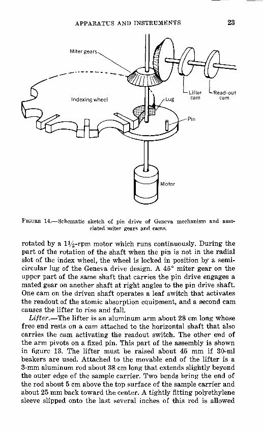
Positioning drive mechanism.-Automatic positioning of the beakers, sequentially and accurately, is controlled by ,an indexing wheel constructed after the Geneva drive design (fig. 14). This wheel is a round brass plate 152 mm in diameter with 16 semicircles and 16 radial slots that alternate around the periphery. The wheel is moved by a plate-mounted drive pin on a shaft
3 Perkin-Elmer Corporation, Norwalk, Connecticut 06852.
APPARATUS AND INSTRUMENTS 23
Miter gears
...... ----------.
Indexing wheel cam
Motor
FIGURE 14.-Schematic sketch of pin drive of Geneva mechanism and associated miter gears and cams.
rotated by a llj2-rpm motor which runs continuously. During the part of the rotation of the shaft when the pin is not in the radial slot of the index wheel, the wheel is locked in position by a semicircular lug of the Geneva drive design. A 45° miter g·ear on the upper part of the same 'Shaft that carries the pin drive engages a mated gear on another shaft at right angles to the pin drive shaft. One cam on the driven shaft operates a leaf switch that activates the readout of the atomic absorption equipment, and a s~econd cam causes the lifter to rise and fall.
Lifter.-The lifter is an aluminum arm about 28 em long whose free end rests on a cam attached to the horizontal shaft that also carries the cam activating the readout switch. The other end of the arm pivots on a fixed pin. This part of the assembly is shown in figure 13. The lifter must be raised about 45 mm if 30-ml beakers are used. Attached to the movable end of the lifter is a 3-mm aluminum rod about 38 em long that extends slightly beyond the outer edge of the sample carrier. Two bends bring the end of the rod about 5 em above the top surface of the sample carrier and about 25 mm back toward the center. A tightly fitting polyethylene sleeve slipped onto the last several inches of this rod is allowed

24 ANALYSIS OF SILICATE, CARBONATE, PHOSPHATE ROCKS
to extend about 25 mm beyond the end of the rod. A hole large enough to accept insertion of the aspirator tube is drilled through the free part of this polyethylene sleeve.
Wiring.-The 1lj2-rpm motor is controlled by an on-off toggle switch. The atomic absorption equipment has a pushbutton switch used to control the readout equipment when a printer is provided. This pushbutton, or readout switch, is connected to the terminals of a normally open leaf switch. The leaf switch is positioned underneath the cam made for this purpose in such a way that as the cam rotates it closes the switch for 2-3 sec. The exact position of the shaft at which this occurs need not be set until attachment is made to the aspirator tube.
Assembly and operation.-The table is positioned so that the lifter arm is close to the aspirator tube which is inserted through the drilled hole in the plastic sleeve. This is facilitated by passing a thin steel wire up through the drilled hole and into the aspirator tube for about 25 mm. The aspirator tube may then be brought through the hole without being crushed, after which the wire is removed. A beaker is plac·ed in the sample-carrier depression just below the aspirator tube, and the motor switched on and allowed to run until the lifter arm is at its highest point. The aspirator tube is then positioned so that its tip is about 3 mm above the top of the beaker.
The cam that activates the readout switch is now loosened, the motor is turned on and allowed to run for 3 sec after the time the lifter reaches its lowest point, and the motor is then turned off. The cam is retightened and is set to close the leaf switch. The procedure may have to be repeated a few times to set the exact position and degree of closing. The equipment is now ready for use, and further adjustment should not be needed.
In the automatic operation, standards and samples are placed in a sequence of 6 standards followed by 15 samples. The flame position and electrical parameters are the same as in manual operation of the atomic absorption equipment when the blank and any one of the standards are used. When the adjustments are correct, the sample carrier is positioned so that the aspirator tube is in the beaker preceding that of the blank, and then the toggle is switched on. The rest of the operation is fully automatic.
The a.spirator tube is lifted to its peak height, the table rotates to bring the first beaker into position, the aspirator tube is lowered into the beaker where it remains for 3 sec, and then the readout is activated. The instrument makes four readings and displays the average in 12 sec. The result is then printed out, and the arm starts up again to repeat the cycie. A slight amount of drift some-
TWO-SOLUTION PROCEDURE 25
times occurs in the readings of the standards before and after a batch of samples. For this reason always average the ~standard readings made before and after a given set of samples. The complete cycle of 64 solutions requires 48 min, or 45 sec per sample.
PREPARATION OF POWDERED SAMPLES
A jaw crusher, a roll crusher, ·and a ceramic plate pulverizer are used to reduce the samples to a powder that will pass a 100-mesh sieve.
PROCEDURE
1. If any of the pieces of the samples are too large for crushing with the jaw crusher, break them with a hardened hammer to a size ·suitable for the crusher.
2. Adjust the j;aw crusher so that it will crush the samples to an ·average dimension of about 1.25 em.
3. Clean the crusher thoroughly and pass all of the first of the series of samples through it.
4. Repeat step 3 for each of the samples. 5. Set the rolls of the roll crusher about 15 mm apart and pass
the first sample through it. 6. Set the rolls of the roll crusher so that they ·are touching, and
again pass the same sample through the crusher. 7. Repeat steps 5 and 6 with each sample, cleaning the crusher
between each sample. 8. Mix thoroughly and split out about 75 g of each sample by
quartering. 9. Take the first of the series of samples and pass through the
pulverizer. 10. Separate the coarse from the fines with a 100-mesh screen. 11. Return the coa.rse material to the pulverizer. 12. Repeat steps 10 and 11 until all the sample passes through the
100-mesh screen. 13. Mix thoroughly and transfer to a 60-ml screwcap jar. 14. Repeat steps 9 through 13 for the remainder of the samples.
TWO-SOLUTION PROCEDURE
PREPARATION OF SOLUTION A
Solution A is used in the determinations of Si02 and Al203. Portions of the samples and standards are decomposed by fusion with NaOH at a comparatively low temperature for about 5 min
26 ANALYSIS OF SILICATE, CARBONATE, PHOSPHATE ROCKS
in nickel crucibles. After cooling, the melts are leached with water, and the solutions are acidified with hydrochloric acid.
Occasionally, with some fine-grained materials such as clays, there is a tendency during fusion for some of the sample powder to float on the surface of the molten NaOH and remain unattacked. When this occurs, the crucible is swirled, allowed to cool, and then reheated so that complete decomposition will result.
For silicate rocks, 50-mg portions of samples and standard are used. This relatively small portion eliminates the necessity for double dilutions, which would be required with larger samples. Furthermore, silicon is known to be unstable in solution above concentrations of 200 ppm: this procedure assures the stability of the silicon. For carbonate or phosphate rocks, a 200-mg portion of sample powder is used.
The high percentages of Si02 in silicate rocks (about 40 to 100 percent) require that the accuracy and precision of this determination be greater than those necessary for most of the other constituents. For this reason, particular care must be given to mixing and weighing the samples, to the fusions, and to the handling of the relatively concentrated solutions of the melts before dilution.
REAGENTS
NaOH solution, 30-percent: Dissolve 450 g of NaOH pellets in 1,500 ml of water in a stainless steel beaker. Cool and store in a plastic bottle.
HCl, 1 + 1 : Prepare 1 I. National Bureau of Standards standard sample No. 70a (feld
spar) or equivalent.
PROCEDURE
1. Transfer 5-ml portions of 30-percent NaOH solution, measured with a plastic graduate, to a series of 75-ml nickel crucibles. One crucible will be needed for each sample, two for standards, and one for a blank. The crucibles should be cleaned with dilute HCl before use.
2. Evaporate the solutions to dryness over gas burners or electric heaters. Slight spattering can be ignored.
3. Accurately weigh (to the neBJrest 0.1 mg) 50 mg of each sample of silicate-rock powder (200 mg of samples of carbonate and phosphate rocks) and two 50-mg portions of National Bureau of Standards sample No. 70a (feldspar). As each portion is weighed, transfer to a crucible containing the fused N aOH.
TWO-SOLUTION PROCEDURE 27
4. Cover and heat the crucibles to dull redness for about 5 min. Remove each crucible from the heat and swirl the melt around the sides. Allow the melts to cool.
5. Transfer the crucibles plus contents to a series of 1-1 plastic beakers.
6. Add about 980 ml of water to each beaker using a rapid 1-1 water dispenser (the exact amount is not important except that the same amount must go into each beaker). Allow to stand for at least 1 hr.
7. Stir the contents of each beaker using a phtstic stirring rod. 8. Use a tilting pipet to add 20 ml of 1 + 1 HCl to each beaker,
stirring each at the time of addition. 9. Use nichrome tongs to lift each nickel crucible out and examine
it; there should be no adhering melt. If any melt remains, allow some more time for dissolution with frequent stirring. When all the melts are dissolved, remove the crucibles and set them aside for washing with HCl before storing them. When the crucibles are removed the solutions are ready to be used for Si02 and Al203 determinations.
PREPARATION OF SOLUTION B
Solution B is used in the determination of total iron, MgO, CaO, Ti02, P205, MnO, Na20, and K20.
The samples are digested on a steam bath overnight with a mixture of HF, H2SOH and HNO:-~. This procedure decomposes almost all the minerals that are normally present.
Organic matter is destroyed by the addition of a few drops of a mixture of perchloric and nitric acids after heating to sulfuric acid fumes. Any manganese dioxide formed by oxidation is then reduced and rendered soluble by the addition of hydrazine sulfate.
Rarely, appreciable residues do remain. If so, they should be removed, identified, and analyzed by suitable methods.
REAGEANTS
Solution B acid mixture: Working under a fume hood, transfer the contents of a 454-g bottle of HF ( 48 percent) to a 1-1 polyethylene bottle. Chill the HF in a bath of cold water. Keep the polyethylene bottle in the cold-water bath, add 165 ml of concentrated H2SO.h mix, and allow to cool. Add 40 ml of concentrated HN03 and mix.
HCl04-HN03 mixture: Mix 100 ml of HC104 (72 percent) and 100 ml of concentrated HN03. Store in a 200-ml glass-stoppered Pyrex bottle.

28 ANALYSIS OF SILICATE, CARBONATE, PHOSPHATE ROCKS
Hydrazine-sulfate solution, 0.2 percent: Dissolve 0.2 g NH2 · NH2 · H2S04 in 100 ml of water. Prepare fresh solution for each run.
PROCEDURE
1. Transfer 0.500 g of each sample to special Teflon beakers (see '.i\pparatus and Instrumenrts;'p. 4).
2. Under a fume hood, add 15 ml of the solution B acid mixture to each Teflon beaker and swirl to wet the sample powder.
3. Cover the Teflon beakers with the Teflon covers, place the beakers in the steam bath so that most of each beaker is suspended in steam, and heat overnight.
4. Remove the covers and continue to heat the beakers on the steam bath for about 1 hr or until acid fumes are no longer emitted.
5. Completely transfer the contents of the Teflon beakers to 400-ml Vycor beakers, using a minimum of water and a policeman to effect the transfer.
6. Place the Vycor beakers on a hot plate and heat until S03 fumes evolve, then remove the beakers~
7. When SOs fuming stops, add about 4 drops of the HC104-HN03 mixture to each beaker from a dropping bottle and replace the beakers on the hot plate. Heat each beaker until strong fumes are evolved and any color caused by organic matter has disappeared. Repeat this step if necessary.
8. Remove the beakers from the hot plate, allow them to cool for a few minutes, and then add about 225 ml of water, 5 ml of concentrated HN03, and 1 ml of the hydrazine sulfate solution.
9. Replace the beakers on the hot plate, and heat to boiling. If a brown precipitate of Mn02 remains after the solutions have boiled for a few minutes, an additional milliliter of hydrazine sulfate should be added. If a residue remains after the solutions have been boiled for a few minutes, boiling should be continued for an additional half hour. A ·small residue can be ignored; an appreciable residue should be sep·arated, identified, and analyzed by suitable me·ans.
10. Cool the .solutions to room temperature, then transfer them to 250-ml volumetric flasks.
11. Dilute to volume, mix, and transfer to polyethylene bottles.

TWO-SOLUTION PROCEDURE 29
DETERMINATION OF CONSTITUENTS Si02 IN SILICATE, CARBONATE, AND PHOSPHATE ROCKS
A ~molybdenum blue method is used for the determination of silica (Si02) (Bunting, 1944). As in the preparation of solution A, factors that govern precision should be given particular attention in order to avoid errors that might •seriously affect accuracy. All of the aliquots of the A solution ~should be precisely ·measured with the same 8-ml pipet. Adequately preci,se measurements can be made with an ordinary transfer pipet, but better precision is assured if a stopcock pipet is used.
The procedures as written are based on the use of a pipetting machine to dispense reagents. Use of this pipet assures a high degree of reproducibility and eliminates the need for the use of volumetric flasks. The force of agitation obtained by its use eliminates the need for stirdng, and, be~cause the aliquots and all reagents are measured precisely, the final volume is the same for blanks, standards, and samples. Even when as few as six samples are being analyzed the mechanical pipet is preferred for the addition of reagents for the Si02 and Al203 determinations.
REAGENTS
Ammonium molybdate solution: Dissolve 6.0 g of (NH4) 6Mo,024 · 4H20 in 11 of water.
Tartaric ~acid solution: Dissolve 16 g of H2C2H.106 in 11 of water. Reducing solution: Place 0.28 g of sodium sulphite, 3.6 g of sodium
bisulphite, and 0.06 g orf 1-amino-2 napthol-4-sulphonic acid into a 1-1 bottle, add 11 of water, and stir to dissolve.
Acidified water: Add 5 ml of 1 + 1 H2S04 to 11 of water. Note: Highly consistent results are readily obtained when these
solutions are prepared fresh, not more than 48 hr before use. To avoid the inconvenience of weighing reagents at the time an analysis is underway, a supply of 12 or more containers of each dry reagent is preweighed at some convenient time and stored for use as required.
PROCEDURE
1. With an 8-ml stopcock pipet, transfer 8 ml of the solution A reagent blank solution, 8 ml of each standard solution, and 8 ml of each sample solution to 150-ml beakers. Add the following reagents, preferably with ·a pipettting machine.
2. Add 25 ml of ~acidified water to each beaker. 3. Add 25 ml of the molybdate reagent to each beaker. Allow to
stand for 10 min.

30 ANALYSIS OF SILICATE, CARBONATE, PHOSPHATE ROCKS
4. Add 23 ml of the tartaric acid solution to each beaker. 5. Add 25 ml of the reducing solution to each beaker. Allow to
stand for at least 45 min. 6. Determine the percent trans.mission for each solution at 640
nm using the reagent blank as the reference, or read percent Si02 using an automated spectrophotometer.
CALCULATIONS
If the automated spectrophotometer described is used, no further calcuJati<lns are needed. Otherwise: 1. Convert the readings from percent transmission to arsorbance
using table 1. 2. Compute the factor :
Percent Si02 in the ·standard
Average of absorbance of standards 3. Compute the percent Si02 in the samples :
factor.
(Factor) X (absorbance orf the sample) = percent Si02. 4. If carbonate or phosphate rocks have been run using 200-m.g
samples, multiply the results obtained in step 3 by 0.25 to obtain percent Si02.
Al20 3 IN SILLCATE AND CARBONATE ROCKS
Alumina (Al20a) is determined by measuring the absorption of light at 475 nm by a solution in which aluminum has been converted to a calcium aluminum alizarin red-S complex (Parker and Goddard, 1950).
When ·50-mg samples are used for the preparation of the A solutions and a 15-ml aliquot is used, the determination can be made on samples containing as much as 24 percent Al20a. For samples containing from 24 percent to 36 percent Al203, a 10-ml aliquot of solution A ~hould be used instead of the usual 15 ml. When a 10-ml aliquot is used, 5 ml of blank solution should also be added to the fla:sk to maintain the same pH and concentration of inert salts as in the standard solutions. Carbonate-rock samples are run using a 200-mg sample.
Appreciable quantities of iron and titanium also form colored complexes that absorb at 475 nm. Interference from iron is eliminated by the use of potassium ferricyanide and thioglycolic acid as complexing agents ; iboth of these reagents are required to completely eliminate this interference. The interference of titanium is not eliminated, but an empirically derived table is provided to correct for the effect of titanium.

TWO-SOLUTION PROCEDURE 31
REAGENTS
Complexing solution: To 880 ml of water add 0.3 g potassium ferricyanide KsFe(CN) 6; 40 ml of hydroxylamine hydrochloride (NH20H · HCI) solution, 10 percent; and 80 ml of a GaCI2 solution (Dissolve 14 g CaC02 in 30 ml concentrated HCI and dilute to 1 1). Prepare this solution the same day it is to be used.
Thioglycolic acid solution : Dilute 3 ml of the pure acid to 1 I with water.
Buffer solution: Dissolve 80 g of sodium acetate NaC2Hs02·8H20, in 975 ml H20 and add 24 ml glacial acetic acid.
Alizarin red-S stock solution, 0.05-percent: Dissolve 0.5 g of the pure dye in 11 of water and filter.
Alizarin red-S, 0.01-percent: Dilute 200 ml of the stock solution to 1 I with water.
PROCEDURE
1. Transfer 15 ml each of the solution A reagent blank, the standard solution, and the sample ·solutions to a series of 150-ml beakers using a high-precision piston pipet. Add the following reagents to each beaker, preferably with a pipetting machine.
2. Add 25 ml of the complexing solution. 3. Add 25 ml of the thioglycolic acid solution. Allow to stand for
5 min. 4. Add 25 ml of the buffer solution. Allow to stand 10 min. 5. Add 25 ml of the 0.01 percent alizarin red-S solution. Allow to
stand for 45 to 75 min. 6. Determine the percent transmission at 475 nm for each solu
tion using the blank solution as a reference, or read percent constituent with an automated spectrophotometer.
CALCULATIONS
If an automated spectrophotometer has been used, correct the values for Ti02 where required as indicated below, step 4. If an ordinary spectrophotometer has been used, make the following calculations: 1. Convert the readings for percent transmission to absorbance
using table 1. 2. Compute the factor :
Percent Al20s in standard factor.
Average absorbance of standards
32 ANALYSIS OF SILICATE, CARBONATE, PHOSPHATE ROCKS
3. Compute the apparent percent Al20a in the samples : (Factor) x (absorbance of s~ample) = apparent percent Al20:~· 4. Correct for Ti02 according to the following: Apparent percent Al,O, Correction per percent TiO,
0 ________________________________________________ 0.25
5------------------------------------------------ .20 10------------------------------------------------ .15 15 ________________________________________________ .10
20------------------------------------------------ .05 (Apparent percent Al20a)- [(Correction per percent Ti02) X
(percent Ti02)] =percent Al20a. If the sample is a carbonate rock and 200-mg samples have been
used, multiply the result obtained in step 4 by 0.25 to obtain percent Al20a.
Al20 3 IN PHOSPHATE ROCKS
Bhosphate rocks normally contain fluorine which tends to lower tl!e alumina w.lues when the concentmtions of both constituents are about 1 percent or higher. This interference is eliminated by volatilization of mos't of the fluorine as fluosilicic acid from the aliquots of solution A by evaporation from Vycor or silica vessels.
Reagents are the same as those for silicat~e rocks (p. 31). It should be noted that fluorine does not affect the Al20a deter
mination when the samples are run by the single ... solution procedure.
PROCEDURE
1. Transfer 15 ml of solution A reagent blank solution and 15 ml of each sample solution to a series of small Vycor beakers or evapo~ating dishes.
2. Evaporate to dryness on a steam bath. 3. To each beaker or dish add 15 ml of solution A reagent blank
solution with a pipet and heat for a few minutes on the steam bath to dissolve the salts, then remove from the steam bath and allow to come to room temperature.
4. Place each beaker upright into a 150-ml beaker. 5. Proceed as in stepJ 2 to 6 of the procedure for aluminum in
·silicate rocks (page 31). Calculations are the same as for carbonate r·ocks.
TOTAL IRON IN SILICATE, CARBONATE, AND PHOSPHATE ROCKS
The method for determining total iron (as Fe20.1) is based on the orange color developed with orthophenanthroline after the
~The correction required may vary with each spectrophotometer, so it is advisable to establish a proper correction for each instrument. The corrections shown are for the .Model B Beckman spectrophotometer.
TWO-SOLUTION PROCEDURE 33
iron is reduced with hydroxylamine hydrochloride and the solution· is buffered with sodium citrate ('Bandemer and Schaible, 1944). When 5 ·ml of solution B is used, the method is designed to accom·modate samples containing from 0 to 15 percent total iron (as Fe203). For the occasional,sample in which Fe20:~ exceeds 15 percent, a smaller aliquot of solution B can be used.
REAGENTS
Hydroxylamine hydrochloride, 10 percent. Dissolve 100 g NH20H · HCl in 1 I of water.
Orthophenanthroline solution, 0.1 percent. Dissolve 1 g C12HsN2· H20 in 1 I of water.
Sodium citrate solution, 10 percent. Dissolve 100 g Na3C6H507 · 2H20 in 1 I of water.
Standard iron :solution: Add 0.4910 g FeS0-1 · (NH-1) 2S0.1 · 6H20 to a 500-ml volumetric flask. Add 16 ml of 1+1 H2SOH 10 ml of concentrated HN03, and about 300 ml of water. Stir until completely dissolved, then add water to the mark, and mix. The Fe203 concentration in thi·s solution is 0.2 mg/ml, which is equivalent to that in a solution prepared from a sample containing 10 percent Fe203.
PROCEDURE
1. With a pipet, transfer two 5-ml portions of the standard iron solution and 5 ml of each saimple solution B to a series of 100-ml volumetric flasks. Use an additional flask for the preparation of a reagent blank solution.
2. With a tilting pipet add 5 ml of the hydroxylamine hydrochloride solution to each fl.ask and allow to stand for 10 min.
3. Add 20 ml of the orthophenanthroline solution to each flask, preferably with a pipetting machine.
4. Add 10 ml of the sodium citrate to each flask with a tilting pipet and dilute to 100 ml with water.
5. After 1 hr determine the percent transmission at 555 nm for each solution by using the blank solution as the 100 percent reference.
CALCULATIONS
If the readings are made on an automatic spectrophotometer they are already in percent, otherwise : 1. Convert the readings for percent transmission to absorbance
using table 1.

34 ANALYSIS OF SILICATE, CARBONATE, PHOSPHATE ROCKS
2. Compute the factor : 10
Average of the absorbances of the standard solutions 3. Compute the percent total iron as Fe20a : (F·actor) X (absorbance of sample solution) =
factor.
percent total iron as Fe20a. Note: Percent Fe20a in the sample is calculated in the usual w·ay
by subtracting the Fe20a equivalent of FeO (separately determined) from the value for total iron as Fe20a: (Percent total iron as Fe20a)- (percent FeO x 1.1) =
percent Fe20a.
Ti02 IN SILICATE, CARBONATE, AND PHOSPHATE ROCKS
The determination of titania (Ti02) is based on the yellow color produced with Tiron ( disodium-1,2-dihydroxybenzene-3,5-disulfonate) (Yoe and Armstrong, 1947). Ferric iron also reacts with Tiron to produce a purple solution that can be decolorized by reduction with sodium dithionite.
Titanium dioxide in the 0- to 3-percent range can be determined with 5 ml of solution B. For higher concentrations, a smaller aliquot of solution B should be taken.
REAGENTS
Tiron (disodium-1,2-dihydroxybenzene-3,5-disulfonate) : Dry reagent powder.
Buffer solution: Dissolve 80 g of ammonium acetate NH4C2Ha02 and 30 ml of glacial acetic acid in 2 I of distilled water.
Sodium dithionite, Na2S204 (sometimes sold as sodium hydrosulfite): Dry reagent powder.
Standard Ti02 solution: Weigh 0.1013 g of National Bureau of Standards standard sample No. 154 (titanium dioxide) or the appropriate amount of reagent Ti02 of known composition. Transfer to a small platinum crucible. Add 2 g of sodium bisulfate, cover, and heat until the sample i'S completely fused, allow to cool amd place the crucible into a beaker containing 125 ml of 1+1 H2S04. Heat and stir until the melt is completely dissolved. Cool, dilute the solution to 250 ml in a volumetric fl·ask, and mix well. With a pipet, transfer 50 ml of the solution to a 1-l volumetric flask, add 40 ml of 1+1 HNOa, dilute to the m•ark, and ·mix. Store the solution in a Pyrex bottle. The concentration of Ti02 is 0.02 mg/ml which is equivalent to that in a solution prepared from a sample containing 1 percent Ti02.

TWO-SOL UTI ON PROCEDURE 35
PROCEDURE
1. With ·a pipet, transfer 5-ml portions of the standard Ti02 solution and 5 ml of each solution B to ·a series of 150-ml beakers.
2. Add 5 ml of water to another beaker, to be used in the preparation of a reagent blank solution.
3. Add about 125 m.g of ·Tiron powder to each beaker with a measuring scoop.
4. Add 50 ml of the buffer ·solution to each solution preferably with a mechanic·al pipetter.
5. Set the spectrophotometer to 430 nm. Add ·about 10 to 20 mg of sodium dithionite to the solution to be used as the reagent blank solution and mix gently ·by rotating the beaker two or three times, but not more, as vigorous mixing will cause sulfur to precipitate.
6. Pour the solution into the absorption cell in the spectrophotometer and adjust the slit width to 100 percent transmission.
7. Add dithionite powder to one of the standard solutions, mix, wait for ·a minute, and obtain the percent transmission. Repeat with each sample solution and the second standard solution. The dithionite may be added to 6 beakers at a time.
CALCULATIONS
If the readings are made on an automated spectrophotometer, they are ·already in percent, otherwise: 1. Convert the readings for percent transmission to absorbance
using table 1. 2. Compute the factor :
1 :factor.
Average of the absorbances of the standard solutions 3. Compute percent Ti02:
(Factor) X (absorbance of sample solution) =percent Ti02.
MnO IN SILICATE, CARBONATE, AND PHOSPHATE ROCKS
The determination of MnO utilizes the intensity of the color of the permanganate ion developed by persulfate with silver as a c•atalyst (Hillebrand and others, 1953). With a sufficiently high concentration of silver, the color can be developed fully in 1 hr at room temperature.
In the determination, 25 ml of solution B is used. This amount is suitable for MnO concentrations ranging from 0 to 3 percent. For the occasional sample in which MnO exceeds 3 percent, a smaller aliquot should be used.
36 ANALYSIS OF SILICATE, CARBONATE, PHOSPHATE ROCKS
REAGENTS
Silver nitrate :solution, 5 percent: Dissolve 5 g AnNOa in 100 ml of water and .store in a dark bottle.
Phosphoric acid, 1 + 1 : Prepare 100 mi. Ammonium persulfate: Dry reagent powder. Acid blank solution: Dilute 16 m1 of 1 + 1 H2S04 and 10 ml of con
centrated HNOa to 500 ml with water. Stand·ard MnO solution: Transfer 0.0531 g of National Bureau
of Standards standard sample No. 25c (manganese o~e) to a 250-ml beaker and add 25 ml of 1+1 HNOa, 64 ml of 1+1 H2S04, and 2 to 3 ml of 3-percent H202. Heat on a hotplate until no bl.ack residue remains. Evaporate and then continue heating until fumes of SOa appear. Cool, add 80 ml of 1 + 1 HNOa cautiously, and dilute to about 250 .mi. If there is a residue, heat until it di·ssolves. Cool Wld dilute to 2 I. The MnO content is 0.02 mg/ml, which is equivalent to that in a solution prepared from a sample containing 1.0 percent MnO.
PROCEDURE
1. Transfer 25 m·l of each of the B ·solutions, ·two 25-ml aliquots of the standard MnO .solution, and 25 ml of the acid blank to a series of 150-ml beakers.
Add the following reagents to each beaker and stir after each addition:
a. 1 ml of 1 + 1 phosphoric acid b. 1 ml of 5 percent silver nitrate solution c. a dipper of ammonium persulfate powder (about 100 mg)
2. Allow the solutions to stand for 1 hr. 3. Add 25 ml of water and mix. 4. Measure the percent transmission for each solut~on at 525 nm,
using the reagent blank solution as the reference.
CALCULATIONS
If the readingts are made on ·an automated spectrophotometer, they are :already in percent. Otherwise : 1. Convert the reading·s for percent transmission to absorbance
using table 1. 2. Compute the factor :
1.0
Average of ·ahsorbances of the standards 3. Galculate percent MnO.
factor.
(Factor)+ (absorthance of sample solution)= MnO.
TWO-SOLUTION PROCEDURE 37
P20 5 IN SILICATE ROCKS
The phosphate (P205) content of a .sample i·s determined by measuring the light absorbed at 420 nm by a solution containing the yellow molybdov·anadophosphoric acid complex (Kitson and Mellon, 1944). The wavelength of 420 nm was chosen to provide adequate sensitivity and to minimize the effect of iron. At this wavelength, each 4 percent total iron as Fe203 in the sample will still cau2e the value of P205 to be hi·gh by 0.01 percent unless a correction is made.
REAGENTS
Molybdova.nadate solution: Dissolve 5.0 g of sodium metavanadate, NaV03, in 400 ml of 1+1 HN03. Dissolve 75 g of sodium molybdate (Na2Mo0-1·2H20) in 400 ml of water. Mix the two ~solutions and dilute to 2 I.
Standard P205 solution: Transfer 0.0950 g of National Bureau of Standards sample No. 56b (phosphate rock) to a beaker. Add 80 ·ml of 1 + 1 HzS04, dilute to 2 I, and filter. The concentration of P 205 is 0.015 mg/ml, which is equiv·alent to that in a ;solution B prepared from ·a sample containing 0.75 percent P205.
PROCEDURE
1. Transfer 2·5 ml of water to serve as a reagent blank, two 25-ml portions of the standard P 205 solution, and 25 ml of each B solution to a series of 100-ml beakers.
2. Add 25 ml of the molybdovanadate solution to each beaker preferably with a mechanical pipet.
3. Allow the solution to stand for 5 min, then determine the percent transmission at 420 nm for the standard solutions and the sample solutions, using the reagent blank solution as the reference.
CALCULATIONS
If the readings are made on an automatic spectrophotometer they are already in percent, otherwise : 1. Convert the readings for percent transmission to absorbance
using table 1. 2. Compute the factor :
0.75 ---------------------factor.
Average of the absorbances of the standard solutions 3. Calculate the apparent percent P 205 :
38 ANALYSIS OF SILICATE, CARBONATE, PHOSPHATE ROCKS
(Factor) X (·absorbance of sample solution) =apparent percent P 205.
4. Correct the apparent percent P 20 5 for the effect of iron : (Apparent percent P205)-(percent iron as Fe20aX0.0025)
=percent P 205.
P20 6 IN CARBONATE ROCKS
U·se the method described above for silicate rocks unless the concentration of P205 exceeds 10 percent, in which case use the method described below for phosphate rocks.
P20 5 IN PHOSPHATE ROCKS
The method for determining P 205 in phosphate rocks is basically the same as that whioh is used for silioote and carbonate rocks. Sample solutions are brought to suitable concentration for color development by d()uble dilution, and standard solutions at three concentration levels are used to establish a reference line.
REAGENTS
Standard P205 solution: Transfer 0.4430 g of National Bureau of Standards standard sample No. 56b (phosphate rock) to a 400-ml beaker. Add about 50 ml of water and 10 ml of concentrat'ed HNOa, cover the beaker, and heat to boiling. Boil for about 5 min and allow to cool. Add about 200 ml of water and 16 ml of 1+1 H2S04, and filter. Dilute to 500 ml in a volumetric flask.
H2S04, 1+7. Molybdovanadate solution: Dissolve 5 g of sodium metavanadate
(NaVOa) in 400 ml of 1+1 HN03 • Dissolve 75 g of sodium molybdate (Na2Mo04 ·2H20) in 400 ml of water. Mix the two solutions and dilute to 2 I with water.
PROCEDURE
1. Use a pipet to transfer 15 ml of each B solution and two 1,5-ml portions of the standard P205 solution to 100-ml volumetric flasks.
2. Dilute the solutions to 100 ml with water and mix. 3. Transfer 15 ml of the dilute B solutions prepared in step 2 to
100-ml volumetric flasks. 4. With the ·same 15-ml pipet that wa-s used above, transfer 15,
30, and 45 ml of ooch solution prepared from the standard P205 solution to additional 100-ml volumetric flasks.
5. To each of the flasks containing aliquots from the B solutions and the standard P 20;; solutions and to one additional flask,
TWO-SOLUTION PROCEDURE 39
which will be used for the reagent blank solution, add 5 ml of the 1+7 H2S04 solution.
6. Add 25 ml of the molybdovanadate solution to each flask from step 5, preferably using a mechanical pipet.
7. Dilute to 100 ml and mix. 8. After 15 'min determine the percent transmission at 420 nm,
using the reagent blank solution as the reference.
CALCULATIONS
1. Convert the readings for percent transmission to absorbance using table 1.
2. Plot the absorbance values for the standard solutions on ordinary coordinate paper. The standards correspond to 14.0, 28.0, and 42.0 percent P 205.
3. Use the absorbances for the samples to read the respective P 205 percentage from the graph.
MgO, Na20, AND K20 IN SILICATE, CARBONATE, AND PHOSPHATE ROCKS AND CaO IN SILICATE ROCKS
The alkaline earths, which were determined by automatic photometric titrations with EDTA in Shapiro and Brannock (1962) and the alkalies previously det~ermined by flame-emission techniques are now being determined by atomic absorption spectrometry. Lanthanurm is added to all blanks, standards, and samples as a releasing ag,ent (Dinnin, 1960), and the four elements are determined directly from the same solution. In general, results can be expected to be± 1-2 percent of the amount present, which is adequate accuracy for these constituents at the levels normally encountered. At levels above 15 percent, the maximum concentration readable without further dilution, a better value for CaO or MgO can be obtained by visual titration with EDTA. For Na20 and K20, a dilution is made, and the solutions are reread more carefully in duplicate or triplicate by AAS.
REAGENTS
Stock standard solution: Transfer 0.8924 g CaC03, 0.9435 g NaCl, 0.7915 g KCl, and 0.3045 g magnesium ribbon 5 to a 500-ml volumetric flask. Add 50 ml of water and 10 ml of concentrated HN03 and heat to dissolve the constituents. Cool, dilute to mark with water, and mix. This solution contains the equivalent of 1.000 mg/ml each of GaO, MgO, Na02, and K20.
s Magnesium ribbon is generally about 99 percent Mg ; therefore, this figure includes a 1 percent correction.

40 ANALYSIS OF SILICATE, CARBONATE, PHOSPHATE ROCKS
Working standard solutions: To each of six 250-ml volumetric fl.31sks add 0, 15, 30, 45, 60, and 75 ml of the stock standard solution. Add about 100 ml of water, 6 ml of H2S04 (1 + 1), and 5 ml of concentrated HN03. Dilute to mark and mix. These solutions represent a blank and 3-, 6-, 9-, 12-, and 15-percent standards, respectively, for each of the four oxides and contain the same acid concentrations as the solution B.
Lanthanum solution: Carefully di·ssolve 58 g La203 (99.99 percent pure or better) in 250 ml of concentrated HCl in a 2-1 beaker. When the reaction has :subsided, dilute to 1 1 with water.
PROCEDURE
1. Transfer 4 ml of the standard solutions and the solution B of each sample, using a transfer pipet, to a series of 200-ml plastic bottles or beakers. Plastic 'bottles are preferable if the ,solutions are to be stored for some time before analysis.
2. Add 16 ml of the lanthanum solution to each bottle, preferably with a mechanical pipet.
3. Add 40 ml of water to each bottle, preferably with a mechanical pipet. These solutions are ready to be analyzed, or, if they are tightly stoppered, they may be stored as long as a month.
4. Atomic absorption measurements are made following the procedures described by the m'anufacturer for the equipment in use. The standard solutions cover the workable range for each constituent and encompass conc,entrations derived from rocks. Where concentrations exceed 15 percent of the rock, the solution B can be diluted appropriately, but accuracy will be diminished unless duplicates or triplicates are run to improve the results.
5. Results are calculated from standard curves made from the standard solutions. As the concentration of these solutions are already ·stated in terms of percent constituent, no calculations are required once the curve is dr·awn.
It ·Should be noted that accuracy tends to be better with digital readout equipment than with dial readouts. With digital readout and the instrument set against a 12- or 15-percent standard, even the low values are read sufficiently accurately. With a dial readout, solutions having concentrations below 3 percent are reread against the 3-percent standard adjusted to give a maximum reading.
TOTAL Ca0+Mg0 IN CARBONATE AND PHOSPHATE ROCKS
Because CaO, P205, and C02 are the major constituents of carbonate or phosphate rocks, a higher accuracy is desirable for them
TWO-SOLUTION PROCEDURE 41
than for the other components of these rocks. The comparatively low level of Al203 and Fe203 in these rocks, and the UJSe of cyanide and triethanolamine (Biedermann and Schwarzenback, 1948; P.ribil, 1953) to complex them makes a visual EDTA titration for CaO plus MgO feasible. Experience has :shown that at the levels found in these rocks the visual titration for CaO+MgO is more accurate than the AAS techniques and is therefore to be preferred.
Calcium carbonate of A.C.S. (American Chemical Society) grade is used as ,a standard. A measured small quantity of magnesium is added to all solutions prior to titration to ensure the presence of sufficient magnesium to convert the dye to its red complex so that the end-point change will be sharp. The titration, always a large one with this type of rock, can be speeded up by deeanting a small portion of the solution to be titrated into a small beaker and then titrating the main portion rapidly, going slightly past the end point. This allows a good view of the appearanee of the end point. When the decanted portion is restored to the main portion, the end point ean then be relocated with more care. A mixed indicator is used to provide a small amount of yellow to serve as ~an internal filter whieh sharpens the appearance of the end point. Without the added yellow, the color changes from red to purple and then to blue, making it difficult to determine the end point. If the yellow is added, the end point is the complete di'Sappearance of red, a distinctly discernible point.
Results obtained for GaO+MgO can be used, with results obtained for MgO by AAS to ealculate GaO.
REAGENTS
Standard solution for GaO+MgO: Transfer 0.500 g of calcium carbonate (low in alkalies), A.C.S. grade, to a 150-ml beaker, add about 25 ml of w,ater and 5 ml of HN03, cover with a watch glass, and bring to a boil on a hot plate. Cool to room temperature, add 8 ml of 1 + 1 H2SO.h dilute with water to 250 ml in a volumetric flask, and mix.
EDT A solution, 0.3 percent: Dissolve 12 g of disodium ethylenedi,amine tetraacetate in 4 I of w,ater.
Erichrome blaek T solution, 0.05 percent: Dissolve 50 mg of the dye in 100 ml of water. Do not store for more than 3d.
Hydroxylamine hydrochloride solution, 10 percent: Dissolve 100 g NH20H·HCI in 11 of water.
Buffer solution: DiHsolve 66 g of NH!Cl in 500 ml of water, add 500 ml of concentrated NH.10H and mix.
42 ANALYSIS OF SILICATE, CARBONATE, PHOSPHATE ROCKS
Complexing solution: Dissolve 64 g of KCN in 600 ml of water, add 400 ml of triethanolamine, and mix.
Methyl red solution, 0.02 percent: Dissolve 200 mg of the pure dye in 1 I of water.
Magnesium sulfate solution: Dissolve 6 g of MgS04 ·7H20 in 1 I of water.
PROCEDURE
1. With a 25-rnl transfer pipet, transfer two aliquots of the standard solution for CaO+MgO, an aliquot of the magnesium sulf·ate solution, and aliquots of each B solution to a series of 400-ml beakers.
2. Add 5 ml of the hydroxylamine hydrochloride solution to each of the beakers and allow them to stand for 5 min.
3. Add about 200 ml of water to each beaker. 4. Add 5 ml of complex.ing solution to each beaker. Use a grad
uate or pipet that does not require mouth suction. 5. Add 25 m1 of the buffer solution to each beaker using a g:md
uate. 6. Add with a transfer pipet 2 ml of the magnesium sulfate
solution to each beaker, including the beaker already containing magnesium sulfate.
7. To one of the solutions containing the standard Ca0+Mg0, ·add 1 m1 of the Erichrome black T solution and 1 ml of the methyl red solution.
8. Decant about 10 ml of the solution into a small beaker and set aside for the moment.
9. Adjust the level of EDTA in the buret to zero, then add the EDTA rapidly to the ·solution in the 400-ml beaker in slight excess of that needed to get complete color change from red to blue.
10. Pour the sol&tion which had been set aside back into the 400-ml beaker. The color of the solution should change back to red.
11. Titrate carefully until the red color of the solution disappears and the solution is dull grey-green in color. This is the end point.
12. Repeat steps 6--11 with each of the sample solutions, the magnesium sulfate solution, and finally with the remaining standard GaO+MgO solution.

SINGLE-SOLUTION PROCEDURE 43
CALCULATIONS
1. Divide the volume for the titration of the magnesium sulfate solution by 13.5 to obtain the volume of the EDTA equivalent to 2 ml of the magnesi urn sol uti on.
2. Subtract the volume of EDT A equivalent to 2 ml of the magnesium solution from each titration volume to obtain the volume of EDT A required for the 25 ml of each solution.
3. The percent CaO in pure OaC03 is 56.0, therefore to calculate a. factor:
56.0 factor.
Average of titration volumes for 25 ml of standards 4. Calculate the percent total CaO+MgO, as CaO in each sample: (F·actor) X (titration volume for 25 ml of the 881mple solution)
=percent Oa:O+MgO calculated as CaO. 5. The result obtained for Ca.O+MgO as GaO is used in the fol-.
lowing manner : Percent MgO (by atomic absorption) X1.39
= CaO equivalent of MgO, then,
CaO+MgO (from step 4) -CaO equivalent of MgO=percent CaO.
SINGLE-SOLUTION PROCEDURE
PREPARATION OF SOLUTION
A single solution suitable for determining the same ten constituents described in the two-solution method can be prepared rapidly by fusing samples with a lithium metaborate-lithium tetraborate flux. The use of lithium metaborate for thi,s purpose was first reported by Ingamells (1964), who later suggested its use with atomic absorption spectrophotometry ( Suhr and lngamells, 1966). Spectrophotometric procedures have also been applied to a solution prepared with a metabol'late flux (Ingamells, 1966; Shapiro, 1967a).
Graphite crucibles are preferred in this laboratory for the fusion procedure because the alternative use of platinum crucibles gives melts which wet the crucible, adhere to it, and are troublesome to dissolve. Because they do not wet the crucible, melts made in gmphite are removed easily in the form of beads. In using lithium metaborate fusions with many sa·mples, it was found that melts of samples containing high iron concentrations (about 15 percent Fe203) would often adhere tenaciously to the crucibles. Lithium tetratborate, a more acid flux than the metaborate, yielded

44 ANALYSIS OF SILICATE, CARBONATE, PHOSPHATE ROCKS
fusions which in spite of their high iron contents parted readily from the graphite isurface. It was found, however, that silica values obtained from solutions prepared from tetraborate melts were erratic, whereas silica determined in solutions prepared from metabomte fusions were excellent. A mixed flux, the proportions of which were determined empirically, led to good parting from the graphite even at iron-ore levels and also yielded good silica results.
Various facto~s must be considered in deciding sample size, flux amount, and sample concentration in order to develop a practical procedure to determine Si02, Al203, GaO, MgO, Na20, K20, Fe203, MnO, Ti02, and P205 in a single solut·ion. The flux-sam.ple ratio should be kept ·as low as possible because even the purest reagents contain impurities that become significant with ·a high flux-sample ratio. The :sample size must al·so be as high a.s possible to ·assure proper sampling of the mixture of minerals of which a rock consists. The quantity of flux plus sample should not be too large, however, because it must fit easily within the graphite crucible and also because the bead must dissolve in a reasonably short time. The concentration of constituents in solution must be sufficiently high to accommodate the least sensitive determinations yet low enough to prevent gel·atinous silica .from precipitating. To satisfy these qualifications, it was decided to use 200 mg of sample and 1.2 g of flux and to dilute the dissolved melt to 250 ml. This provides a solution in which SI02, Al203, total Fe as Fe203, Ti02, P205, and MnO can be determined by simple spectrophotometric procedures, and CaO, ·MgO, Na20, and ·K20 can be determined by AAS using procedures which, except for P 205, are very similar to those described for the two-solution method. The presence of .silica in the single-solution precludes the use of the vanadomolybdate procedure for small amounts of P 205, so this procedure is in this case replaced by a molybdenum blue procedure that c·an be used in the presence of Si02. With c·arbonate and phosphate rocks the high contents of CaO and P 205 are determined with better accuracy using the two-solution procedures.
REAGENTS
Flux mixture: Thoroughly mix 1 part of reagent-grade powdered anhydrous lithium metaborate, LiB02, and 2 parts of anhydrous lithium tetraborate, Li2B407. This mixture can be stored -in a tightly closed bottle-so at least several hundred grams of the mixture should be prepared.
HN03, 1+1: Prepare 1 I.

SINGLE-SOLUTION PROCEDURE 45
Standard samples: Analyzed ·samples which can be carried through the procedure along with the unknown samples serve best as standards. In the U.S. Geological Survey a well-analyzed diabase is used as a standard for Si02, Al203, total Fe, CaO, MgO, Ti02 and as an internal check on K20, Na20, P205, and MnO. The other standards described for the two-.solution procedures can be used for all of the constituents. Bureau of Standards standard sample Feldspar No. 70a is suitable for Si02 and Al203 standards.
Graphite crucibles: Cylindrical, 25-mm (20 mm ID), of high purity g~aphite.
PROCEDURE
1. Transfer approximately 1.2 g of flux mixture to a waxed or plastic-coated weighing paper.
2. Weigh and transfer to the flux mixture 0.2000 g of finely ground sample powder.
3. Mix by rolling successive corners of the paper about 10 times, and transfer carefully and completely to an unused graphite crucible.
4. Wei,gh the s~tandard sam·ples along with the unknown samples, and also carry along a crucible containing only the flux mixture to serve ·as a blank.
5. Tamp down the powders by tapping each crucible several times against the table surface.
6. Fuse in a muffle at 1,0oooc for 1 hr. 7. While the fusions are in the muffle, place a 2-1 flask of dis
tilled water on a hot plate and bring to a boil. 8. Remove the crucibles from the muffle and allow to cool. When
cool, the beads produced should be easily dislodged from the crucibles with the touch of a spatula.
9. To each of a series of 250-ml plMtic bottles add a Tefloncovered 39-mm magnetic stirring bar. Longer stirring bars tend to cause the bottles to walk during stirring. Transfer the beads to the bottles. Add 50 ml of boiling water to each bottle using a plasic graduate. Transfer to magnetic stirrem.
10. Turn the stirrers on, and, using a tilting pipet, add 5 ml of the 1+1 HN03 to each flask.
11. Stir rapidly for about 60 min. The beads normally dissolve in about 20 min, but the additional stirring may be needed in some cases, particularly with phosphate and carbonate rocks. Stir until the beads dissolve completely.
46 ANALYSIS OF SILICA'l'E, CARBONATE, PHOSPHATE ROCKS
12. Remove the bottles from the stirrers, and add about 100 ml of water to each. Using a funnel in order to catch the stirrer, pour the solutions in turn into a 250-ml volumetric flask. Rinse the bottle briefly, then add water to the volumetric flask to mark, mix, and pour the solution back into the plastic bottle for storage. Rinse the flask between samples.
DETERMINATION OF CONSTITUENTS Si02 IN SILICATE, CARBONATE, AND PHOSPHATE ROCKS
Silica (Si02) in concentrations which exceed about 200 ~tg/ml forms polymers which will not react with the molybdate reagent. It was found however (Shapiro, 1974) that the presence of fluoride ions at the proper concentration leads to depolymerization. The procedure for the determination is similar to that described with the two-solution method. Plastic beakers must be used because glass beakers are sufficiently attacked by the N,aF solution to lead to erratic results.
REAGENTS
Ammonium Molybdate solution: Dissolve 6.0 g of (NH4) sMo7024 · 4H20 in 1 1 of water.
Tartaric acid solution: Dissolve 16 g of H2C2H40s in 1 I of water. Reducing solution: Dissolve 0.28 g of sodium sulphite, 3.6 g of
sodium bi,sulphite, and 0.06 g of 1-amino-2 naphthol-4-sulfonic acid in 11 of water. Prepare within 48 hr of use.
NaF, 3-percent solution. Dilute ~sodium fluoride solution: Dilute 20 ml of the 3-percent Na,F
solution and 5 ml of 1+1 H2S04 to 1 I with water.
PROCEDURE
1. Transfer 0.500-ml aliquots of the blank, the standards, and the sample solutions to a series of plastic 100-ml or 150-ml beakers. It is best to use a high-precision 0.500-ml pistontype pipet although a w~ater repellant-coated 0.5-ml quantitative pipet is acceptable. If the silica is expected to be low, a:s in ca;rbonate and phosphate rocks, use a 2.00-ml aliquot. Add the following reagents, preferably with a pipetting machine.
2. Add 25 ml of the dilute sodium fluoride solution to each beaker. Allow to stand 5 min.
3. Add 25 ml of the molybdate reagent to each beaker. Allow to stand for 10 min.

SINGLE-SOLUTION PROCEDURE 47
4. Add 25 ml of the tartaric acid solution to each beaker. 5. Add 25 ml of the reducing solutions to each beaker. Allow to
stand for at least 45 min. These colors are stable for at least the remainder of the day.
6. Determine the percent transmission for each solution at 640 nm using the reagent blank as reference, or read percent Si02 using an automated spectrophotometer.
Calculations are the same as those used for the two-solution method, but if carbonate or phosphate rocks have been analyzed using a 2-ml aliquot for the sample, multiply the result obtained in step 3 by 0.25.
Al20a IN SILICATE, CARBONATE. AND PHOSPHATE ROCKS
The reagents, procedure, and calculations are identical to those described for the two-solution procedure (see the section called '~l203 in Silicate and Carbonate Rocks"p. 31) except that a 0. 750-ml aliquot is transferred instead of a 15-ml one.
Note that if fluoride is present, as is common with phosphate rocks, the aluminum determination is not affected; the two-solution procedure for Al203 requires a separation of fluorine when present.
TOTAL IRON IN SILICATE, CARBONATE, AND PHOSPHATE ROCKS
The procedure is similar to that described for the-two-solution method, except for aliquot size. The comparison standard used may be a known sample or an external standard prepared as described under Reagents.
REAGENTS
Hydroxylamine hydrochloride, 10 percent: Dissolve 100 g NH20H · HCI in 1 I of water.
Orthophenanthroline solution, 0.1 percent: Dissolve 1 gm orthophenanthroline in 1 I of water.
Sodium citrate solution, 10 percent: Dissolve 100 g Na3CsH50r· 2H20 in 1 I of water.
Standard iron solution: Transfer 0.1964 g of FeS04 · (NH4) 2S04 · 6H20 (Mohr's salt) to a 500-ml volumetric flask. Add 10 ml of 1 + 1 HN03, about 300 ml of water and 2.4 g of flux mixture. Stir to dissolve. This solution corresponds to 10.00 percent Fe203 for aliquots taken in this procedure.
48 ANALYSIS OF SILICATE, CARBONATE, PHOSPHATE ROCKS
PROCEDURE
1.. Transfer 5 ml of the blank, standards, and s·ample solutions to a series of 150-ml beakers.
2. Add 5 ml of the hydroxylamine hydrochloride solution, preferably using a tilting pipet or pipetting machine. Allow to
stand for 10 min. 3. Add 20 ml of the orthophenanthroline solution to each beaker
as in step 2. 4. Add 10 ml of the sodium citmte to each beaker as in step 2. 5. Add 50 ml of water and mix. Allow to stand for 1 hr. 6. After 1 ·hr determine the percent transmission at 555 nm for
each solution using the blank ·solution as the reference, or read percent constituent on an automated spectrophotometer.
CALCULATIONS
If the automated spectrophotometer is not used, determine percent constituent as follows : 1. Convert the readings for percent transmission to absorbances
using table 1. 2. Compute the factor :
Percent Fe203 in the standard
A vemge absorbance of standards 3. ( F·actor) X (absorbance of samples)
factor.
=percent total Fe as Fe203. 4. (Percent total Fe as Fe203)-(percent FeOx1.1) =Fe203.
T•i02 IN SILICATE, CARBONATE, AND PHOSPHATE ROCKS
The procedure is identical to that described for the two-solution procedure under Ti02 in ·silicate carbonate, and phosphate rocks, except that 10-1ml aliquots rather than 5-ml aliquots are used.
REAGENTS
Tiron (disodium-1,2-dihydroxybenzene-3,5-disulfonate) : Dry reagent powder.
Buffer solution: Dissolve 80 g of ammonium acetate NH4C2H302 and 30 ml of glacial acetic acid in 2 I of distilled water.
Sodium dithionite, Na2S204 (sometimes sold as sodium hydrosulphite) : Dry reagent powder.
Standard Ti02 solution: Weigh 16.2 mg of N!ational Bureau of Standards standard sample No. 154 (titanium dioxide) and tmnsfer to 1.2 g of flux mixture. Fuse and prepare as for a regular single-solution analysi•s except that 20 ml of 1+1

SINGLE-SOL UTI ON PROCEDURE 49
HNOa is used to dissolve_the melt. After solution, dilute to 1 I in a volumetric flask. This solution corresponds to 2.0-percent Ti02. Alternatively any well-analyzed rock can be used to prepare a single solution to serve as a reference standard.
PROCEDURE
1. With a pipet transfer 10-ml portions of the blank, standards, and samples to ,a series of 150-·ml beakers.
2. Add approximately 125 mg of T·i'ron powder to each beaker with a measuring scoop.
3. Add 25 ml of the buffer solution to each beaker, preferably a pipetting machine, then add 50 ml of water.
4. Set the .spectrophotometer to 430 nm. Using a spatula add 10-20 mg of sodium dithionite to the bl'ank solution and mix gently by rotating the beaker two or three times ; more vigorous mixing will cause sulfur to precipitate.
5. Pour the solution into the absorption cell of the spectrophotometer ·and adjust the slit width to give 100 percent transmission.
6. Add dithionite powder to the next 10 beakers. One at a time, rotate each beaker once or twice to decolorize the purple color of the iron complex, pour into the absorption cell, and measure the percent transmission.
7. Repeat step 6 with the remainder of the solutions. They are taken 10 at a Ume to limit the time between dithionite addition and the reading of the percent transmission.
CALCULATIONS
If the automated spectrophotometer is not used, determine percent constituent as follows : 1. Convert the readings for percent trans,mission to absorbances
using table 1. 2. Compute the factor :
Percent Ti02 in standard factor.
Average absorbance of the standard solutions 3. (F~actor) X (absorbance of sample solutions) =percent Ti02
MnO IN SILICATE, CARBONATE, AND PHOSPHATE ROCKS
The MnO determination is ~similar to that described for the twosolution procedure.

50 ANALYSIS OF SILICATE, CARBONATE, PHOSPHATE ROCKS
REAGENTS
Silver nitrate solution, 5-percent. Phosphoric acid, 1+1 with water. Arnmoni urn pemulphate : Reagent grade ( NH4) 2S20s. Standard MnO solution: Transfer 0.0215 g of National Bureau of
Standards standard sample No. 25c (manganese ore) to 1.2 g of flux mixture, fuse, and prepare as a regular single-solution (·see p. 45) except that after the pellet is dissolved -add an additional 35 ml of 1+1 HN03 and dilute to 2 1. This solution is equivalent to 1.0 percent MnO.
PROCEDURE
1. Tmnsfer 50 ml each of the blank, standards, and sample solutions to a series of 100-ml beakers. Add the following reagents to each beaker, mixing after each addition:
2. Add about 100 mg of ammonium persulfate powder by dipper, mix.
3. Add 1 rnl of 1+1 phosporic acid, mix. 4. Add 1 ml of 5-percent silver nitrate solution, mix. 5. Allow the solutions to stand for at least 1 hr. These colors are
stable for the remainder of the day. 6. Measure the percent t·ransmission for each solution at 525 nm
using the blank solution as the reference, or read percent constituent on an automated spectrophotometer.
Calculations are the same as those used for the two-solution method (see p. 36) .
P20 5 IN SILICATE AND CARBONATE ROCKS
The reagents used in the two-solution method for P 205 react with the silicate present in the single-solution, therefore an alternate molybdeum-blue procedure is used for the ·single solution. Absorbance is linear to about 2 percent P 205. If the concentration of P 205 is 10 percent or above, the procedure for phosphate rocks is used; if it lies in the 2-10 percent range, the procedure described for silicate and carbonate rocks is used with a smaller aliquot of the single solution.
REAGENTS
Ammonium molybdate solution: Dissolve 12.5 g of (NH4) sM01024 ·4Hz0 in 340 •ml of H20, then ·add 160 ml of 1 + 1 H2S04.
Stannous chloride solution: Transfer 1 g of SnCl2 · 2H20 to a small beaker and dissolve completely in 75 ml of concentrated HCI.

SINGLE-SOLUTION PROCEDURE 51
Dilute to 3.5 I with water. This solution should be prepared within 3-4 hr of the ti•me it i.s to ,be used.
Standard P205 ·solution: Using 200 mg of the National Bureau of Standards standard sample 56b (phosphate rock), prepare a single solution after fusing with the flux mixture. This yields a standard containing 31.7 percent P205 • Transfer 31.7 ml of this solution to ·a 1-l volumetric flask and add 5 ml of 1+1 HNOa and dilute to volume. This is the 1-percent P 205 working solution.
PROCEDURE
1. Transfer 10-ml portions each of the blank, the 1-percent standard, and the sample solutions to a series of 150-ml beakers.
2. Transfer 50 ml of the stannous chloride solution to a graduate. Set a timer for 10 min ; then, to one beaker at a time, add 0.5 ml of the am.monium molybdate solution (using a squeeze pipet); then, promptly add the stannous chloride solution and mix. Refill the graduate with stannous chloride before proceeding to the next beaker so that the time between addition of molybdate and stannous chloride will be as short as possible.
3. Add the two reagents to as many beakers as the 1 0-min time span will allow, then measure the transmittance of each at 640 nm, using the blank as reference. The blue color that develops reaches a peak in about 3 min and remains stable for about 20 min. Ten solutions can easily be measured in this time.
4. Repeat steps 2 and 3 with the remainder of the solutions, working with groups of ten.
CALCULATIONS
1. Convert the reading for percent transmission to 8ibsorbance using table 1.
2. Compute the factor: 1
factor. Absorbance of standard
3. (Factor) X (absorbance of ·sample) =percent P205.
P20 5 IN PHOSPHATE ROCKS
Determine P205 values down to about 10 percent in phosphate rocks by the ·molybdovanadate procedure similar to that described for the two-solution method; modifications must be made, how-

52 ANALYSIS OF SILICATE, CARBONATE, PHOSPHATE ROCKS
ever, to take into account the difference in dilution. For levels between 2-10 percent P205 , use the procedure for silicates, except that 2-ml rather than 1 o .... ml aliquots of the sam,ple are taken and added to 8 ml of the blank.
REAGENTS
H2SO4, 1 + 7 : Prepare 500 mi. Standard P20s solution: Prepare a single-~solution of National
Bureau of Standards standard sa.mple 56b (phosphate rock) using 200 mg of sample. This i,s a standard 31.7-percent P20s solution.
Molybdovanadate ~solution: Dissolve 5.0 g of sodium meta vanadate (NaVOa) in 400 ml of 1+1 HNOa. Dissolve 75 g of sodium molybdate (Na2Mo04 ·2H20) in 400 ml of water. Mix the two ·solutions and dilute to 2 1 with water.
PROCEDURE
1. Prepare a 1+1 dilution of the standard solution by transferring to a small dry beaker 5 ml of the ~standard solution of phosphate rock and 5 ml of water; use the same pipet for each transferral. Swirl to mix.
2. Aline a series of 100-ml volumetric fl,asks. U·sing a 3-;ml pipet, transfer an aliquot of sample blank solution to the first flask, an aliquot of the 1+1 dilution prepared in step 1 to the second, an aliquot of the standard solution to the third, an aliquot of the standard solution plus an aliquot of the 1+1 dilution prepared in step 1 to the fourth, and an aliquot of each of the sample solutions to the remainder of the flasks.
3. With a squeeze pipet transfer 5 ml of 1+7 H2S04 to each of the fl·asks.
4. Pipet 25 ·ml of the molybdovanadate solution into each of the flasks.
5. Dilute to the mark with water and mix. 6. After 15 min ~measure the percent transmission at 420 nm us
ing the ·blank solution as the reference.
CALCULATIONS
1. Covert the readings for percent transmission to absorbances using table 1.
2. Plot the aJbsorbance values for the three standard solutions against P205 concentration on ordinary coordinate paper. The 1+1 dilution represents 15.8 percent, the standard repsents 31.7 percent, and the standard plus the 1+1 dilution
SINGLE-SOLUTION PROCEDURE 53
represents 47.5 percent P20s. The plot should be very nearly a straight line.
3. Use the absorbance for the samples to read the respective P 20s percentages from the graph.
MgO, Na20 AND K20 IN SILICATE, CARBONATE, AND PHOSPHATE ROCKS AND CaO IN SILICATE ROCKS
These elements are determined by AAS a~s in the two-solution method except for some modifications arising from the differences in ~solution composition. In the two-solution method sulfate is present but silica is absent. In the single-solution method the reverse is true but borate is also present. As a result, the standard solutions must also be different. Here, as in the two-~solution method, with sufficient dilution calcium in limestone·s and phosphate rocks can be determined to about 2 relative percent, but a better result can be achieved through a visual titration for CaO+MgO using EDT A as described in the two-solution procedure.
REAGENTS
Lanthanum solution: Transfer 140 g of lanthanum oxide, La203 (99.997 percent pure) into a 2 I beaker. Add 300 ml of concentrated HCI, slowly, allowing time for the reaction to be completed after each addition of acid. The large beaker reduces difficulties from .spatter. After all the acid is added, the oxide will have been dissolved and converted to the chloride. Add 200 ml of H20. Each 4 ml of this solution contains approximately 1 g of La.
Stock standard solution: Transfer 0.8924 g CaC03, 0.9435 g NaCl, 0.7915 g KCl, all of reagent grade, and 0.3045 g magnesium ribbon 6 to a 500-~ml volumetric flask. Add 50 ml of water and 10 ml of concentrated HCI. Boil to dissolve ·the constituents. Cool, dilute to volume with water, and mix. This solution contains the equiv·alent of 1.000 mg/ml each of CaO, MgO, Na20 ·and K20.
Working standard solutions: To each of six 250-ml volumetric flasks add 0, 6, 12, 18, 24, and 30 ml of the stock standard solution. Add 1.2 g of flux mixture, 5 ml of 1+1 HN03 and about 200 ml of water. Mix and dissolve. Dilute to mark with water and mix. These represent a blank, 3-, 6-, 9-, 12-, and 15-percent standard solutions for the single solutions.
a Magnesium ribbon is generally 99 percent Mg, therefore this figure includes a 1-percent correction.
54 ANALYSIS OF SILICATE, CARBONATE, PHOSPHATE ROCKS
PROCEDURE
1. Transfer 10 ml of the sample solutions and the working standard solutions to a series of small beakers, or plastic bottles if the solutions ·are to be stored for later use.
2. Add 1.5 ml of the lanthanum solution to each beaker and mix. Add 25 ml of water and mix.
3. Use AAS equipment, and follow the procedure recommended by the manufacturer. If the instrument is not one of high sensitivity, it is advisable to scan all of the solutions quickly for each constituent to differentiate those below 3 percent from those above. Reread those below 3 percent using the 3-percent ·standard to set the reading at a maximum. Reread thos·e above 3 percent between the appropriate standards. It is important to bracket the sample readings between standards, as the responses are not quite linear, but otherwise there are no interelement or other interferences to affect the results adversely. If CaO or MgO exceeds 15 percent, better results are obtained using the total CaO+MgO titration described below. If N·~O or K20 exceeds 15 percent, prepare more dilute solutions from the .single solution, then proceed starting from step 1 above.
TOTAL Ca0+Mg0 IN CARBONATE AND PHOSPHATE ROCKS
Total CaO+MgO i·s determined in carbonate and phosphate rocks by visual titration with EDT A exactly as is done in the twosolution procedure, except that 50 rni of the single solution is used in place of the 25 ml used for the two-sol uti on method. The standard is a sol uti on prepared from 200 mg of CaC03 dis·solved in 5 ml 1+1 HN03 and diluted to 250 ml with water. The percent MgO in the sample, obtained by AAS, is multiplied by 1.39 to obtain its equivalent as CaO, which is then subtracted from the CaO + MgO to obtaJin percent CaO. See page 42 for the complete procedure.
DETERMINATIONS ON SEPARATE SAMPLES
H 20 IN Sll.ICA TE, CARBONATE, AND PHOSPHATE ROCKS
Water (H20) in rocks is usually considered to be moisture easily driven off at 105°-110°C, designated as H20-, and combined water, designated as H20+. The latter is driven off only at much higher temperatures. These are arbitrary divisions that provide a workable basis for ·analysis, but it ·must be recognized that water

DETERMINATIONS ON SEPARATE SAMPLES 55
may ,be present in ·a variety of ways which are obscured by this classification.
In the U.S. Geological Survey, the H20- value is obtained by loss of weight of a 1-g sample after it is dried overnight at ll0°C. No further description of this procedure need be given. Total water is determined in a separate sample using the procedure described below. H20+ is obtained by subtracting the H20- value from that for total water.
In the determination of total water, water is driven from the sample when it is heated in a Pyrex test tube with sodium tungstate as a flux (Shapiro and Brannock, 1955b). The water is condensed on a piece of preweighed filter paper in the upper part of a test tube, which i·s cooled by crushed ice in a polyethylene jacket surrounding the test tube during the analysis.
The cooling jacket is made from a 230-ml polyethylene bottle by cutting the top portion off with shears, and cutting holes in the sides with a cork borer to permit insertion of the test tube. The apparatus is shown in figure 15.
REAGENT
Sodium tungstate, anhydrous powder: Heat s·everal hundred grams of reagent grade Na2W04 ·2H20 overnight at 180°C in a drying oven. Allow to cool, grind to a fine powder, and .store in an open container in the drying oven.
PROCEDURE
1. Weigh 1.000 g of sample powder, mix with 2 g of anhydrous sodium tungstate and transfer, with a funnel, to ·a dry 18X150-mm Pyrex test tube.
2. Cover the fingers of one hand with rubber finger stalls or a rubber glove, roll a piece of 50 X 50-mm filter paper into a cylinder, slip it into an 18X65-mm weighing tube, stopper the tube with a solid rubber stopper, and weigh. The fingers are covered to avoid transfer of moisture from the fingers to the paper.
3. Quickly transfer the paper cylinder from the weighing tube to the upper part of the 18 X 150 ... mm test tube that contains the sample powder and stopper with a one-holed stopper.
4. In·sert the test tube into the polyethylene cooling j-acket as shown in figure 15, and put crushed ice into the jacket so that the p·art of the tube enclosed by the jacket is well covered.
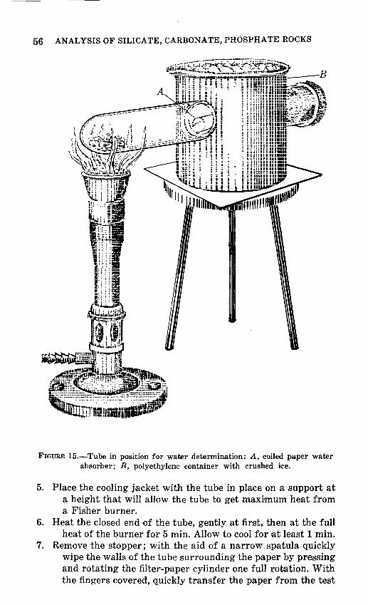
56 ANALYSIS OF SILICATE, CARBONATE, PHOSPHATE ROCKS
FIGURE 15.-Tube in position for water determination: A, coiled paper water absorber; B, polyethylene container with crushed ice.
5. Place the cooling jacket with the tube in place on a support at a height that will allow the tube to get .maxi,mum heat from a Fisher burner.
6. Heat the closed end of the tube, gently at first, then at the full heat of the burner for 5 min. Allow to cool for at least 1 min.
7. Remove the stopper; with the aid of a narrow spatula quickly wipe the walls of the tube surrounding the paper by pressing and rotating the filter-paper cylinder one full rotation. With the fingers covered, quickly transfer the paper from the test

DETERMINATIONS ON SEPARATE SAMPLES 57
tube to the weighing tube and replace the stopper in the weighing tube.
8. Weigh the tube containing the filter paper plus the absorbed water.
CALCULATIONS
1. Subtract the weight for the weighing tube plus the paper strip obtained in step 2 from the weight for the weighing tube and paper ·strip plus water in step 8 to obtain the weight of absorbed water.
2. Calculate percent water : (Absorbed water, in g) X100=percent H20.
FeO IN SU..ICATE, CARBONAT~ AND PHOSPHATE ROCKS
Ferrous iron (FeO) is determined by titration with a standard dichromate solution using diphenylamine sulfonic acid as the indicator (Sarver, 1927). The sample is decomposed by boiling with HF-H2S04. A spike consisting of a small known amount of ferrous ammonium sulfate solution is added to the sample solution just before starting each titration to assure a definitive end-point change for samples containing very small amounts of FeO. The use of a sequential heating device, figure 7, facilitates the uniform boiling of batches of samples.
REAGENTS
H2S04, 48 percent HF, K2Cr207 , boric acid crystals, all (A.C.S.) American Chemical Society grade. H2SO:., 1+3. Diphenylamine sulfonate indicator solution: Dissolve 0.2 g of
sodium diphenylamine sulfonate in 1 1 of 1+1 H2S04. Add 11 of 85-percent H3P04 and mix.
Standard dichromate solution: Weigh 2.728 g of dry National Bureau of Standards potassium dichromate (K2Cr20,) or other pure dry potassium dichromate and dilute to 2 I in a volumetric flask. The solution equivalent is 2.000 mg/ml of FeO.
FeO spike solution: Dis·solve approximately 0.5 g of ferrous ammonium sulfate FeS04(NH4)2S04·6H20 in 500 ml of water containing a few milliters of H2S04.
PROCEDURE
1. Weigh 0.500-g samples and transfer to 100-ml platinum crucibles.
58 ANALYSIS OF SILICATE, CARBONATE, PHOSPHATE ROCKS
2. In a fume hood add 10 ml of 1+3 H2S04, and, with a plastic graduate, add 5 ml of HF.
3. Cover the crucibles and bring to a boil on the sequential heating device; boil gently for 10 min.
4. While the crucibles are heating, add about 15 ml of the indicator solution with a graduate and 5.0 ml of the spike solution with a squeeze pipet to 800-ml beakers containing about 300 ml of water saturated with boric acid and stir.
5. After each crucible has been boiling for 10 min, remove it from the heating device with tongs and i,mmediately immerse it in the solution contained in one of the 800-ml beakers.
6. With the aid of a stirring rod, remove the crucible from the beaker, rinse it with water and set it aside.
7. Titrate the solution with the standard dichromate solution to a purple color that persists for 20 to 30 sec.
~· For each batch of samples, standardize the spike solution by transferring 25.0 ml to a solution containing about 300 ml of water saturated with boric acid, about 20 ml of 1+3 H2SO." and 15 ml of indicator solution and titrate as described in step 7.
CALCULATIONS
1. Divide the titration volume obtained for 25 ml of spike solution by 5 to obtain the blank.
2. St=.btract the blank from each of the titration volumes to obtain milliliters of dichromate required for the sample.
3. Compute percent FeO in the sample : (ml of dichromate) X0.4 =percent FeO.
C02 IN Sll..ICATE ROCKS
The concentration of carbonate ( C02) in rocks can range from 0 to 47 percent. Silicate rocks rarely contain more than several percent C02, ~and approximately 80 percent of those that have passed through the U.S. Geological Survey laboratory have contained 0.1 percent or less. A very rapid scanning technique was developed to differentiate those samples containing more than 0.1 percent from those containing less and simultaneously to provide a value ± 0.02 percent absolute for those having less than 0.1 percent (Shapiro, 1971). For samples with more than 0.1 percent and as much as about 3 percent, a simple method (Shapiro and Brannock, 1955a) is used that employs a glass tube with a side arm (fig. 9) for the evolution and measurement of the gas. For those

DETERMINATIONS ON SEPARATE SAMPLES 59
samples in which the concentration of C02 exceeds 3 percent, one of the methods described for carbonate rocks is used.
RAPID SCANNING TECHNIQUE FOR LOW LEVELS OF C02
Carbon dioxide evolved from a 25-mg sample of pulverized rock is caught in a small bulge of a modified test tube as shown in figure 8 and its volume is estimated by comparison with a similarly processed standard. The method is restricted to C02 concentrations up to 0.10 percent and is especially applicable to most igneous rocks and silicate minerals. Samples can be analyzed at the rate of 2 min each.
Mercuric chloride is added to the samples to react with metallic iron which is frequently introduced during the grinding process. Without this precaution, hydrogen gas would be produced along with the carbon dioxide.
APPARATUS AND REAGENTS
Small borosilicate test tube, 10X75 mm: Modified by addition of a bulge about 18 mm from the bottom of the tube; the bulge is made by heating the test tube over a bunsen burner flame and pressing from within with an opened paper clip having a small hook at one end (figure 8).
Small dipper: Made to hold approximately 25 mg of powdered sample. Prepared by drilling a hole 3 mm in diameter and 3 mm deep into the end of a 6 mm round brass bar.
Test tube clamp. Desk lamp. Hotplate. Squeeze-type pipet: Suitable for transferring 0.1-0.2 ml of liquid. Bunsen burner. Wash bottle with water. Saturated mercuric chloride solution: Saturate 100 ml of water
with HgCl2. Acidified mercuric ehloride solution: Transfer 20 ml of the sat
urated solution to a small beaker and add 20 ml of concentrated HCI.
Standard rock powder containing approximately 0.1 percent C02: This laboratory uses a granite which contains 0.08 percent C02.
PROCEDURE
1. Place the beaker containing acidified mercuric chloride solution on a hotplate set to keep the solution nearly boiling. Allow enough time for this solution to get hot.

60 ANALYSIS OF SILICATE, CARBONATE, PHOSPHATE ROCKS
2. Transfer approximately 25 mg of the standard powder to the modified test tube with a dipper.
3. Add water to about 6 mm above the bulge. 4. Bring the contents of the test tube c·autiously to the boiling
point by passing the tube in and out of the Bunsen burner flame.
5. Hold the tube vertical and tap it gently to displace bubbles trapped in the bulge, then tilt the tube about 45° keeping the bulge on the upper side.
6. Use a squeeze pipet to squirt 0.1-0.2 ml of the hot acidified mercuric chloride into the tube. It is important, for best reproducibility, that both the sample solution and the acid be hot.
7. Observe the accumulation of bubbles in the bulge after about 10 sec. With a standard rock material containing about 0.08 percent C02, the C02 bubble should occupy more than half the bulge. The amount noted serves as the 0.08-percent reference.
8. Rinse out the contents of the tube. Drying is unnecessary. 9. Repeat steps 2 through 7 with each sample, and note the
amount of acoomula.ted gas !in the bulge relative to the amount produced by the standard.
CALCULATIONS
1. If a .sample yields approximately the sam.e volume of C02 as the standard, it is reported as having the same C02 content. If it is roughly half it would be called 0.04. Estimates rarely vary by more than ± 0.02 percent C02.
2. If the volume exceeds the capacity of the bulge by more than a small amount, the carbon dioxide content is too high to be accurately determined by this method; such samples should be analyzed by other available procedures. Rougher estimates made using a dipper one-tenth the size of the one described, will yield results which can be in error by an order of magnitude.
TECHNIQUE FOR DETERMINING CO, CONTENT ABOVE 0.1 PERCENT IN SILICATE ROCKS
Sample powder, solid mercuric chloride, mercuric chloride solution, paraffin oil, and HCl are added to the middle range carbonate tube and the sample is decomposed by heating the lower part of the tube in a heating block that is maintained at 145° ±5° C.
A 1-g portion of sample is used for samples in which the concentration of C02 ranges from 0 to about 1.5 percent and a 0.5-g
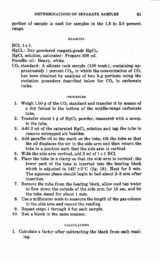
DETERMINATIONS ON SEPARATE SAMPLES 61
portion of sample is used for samples in the 1.5 to 3.0 percent range.
REAGENTS
HCl, 1+1. HgCl2 : Dry powdered reagent-grade HgCl2. HgCl2 solution, saturated: Prepare 500 mi. Paraffin oil: Heavy, white. C02 standard: A silicate rock sample (100 mesh), containing ap
proximately 1 percent C02, in which the concentration of C02 has been obtained by analysis of two 5-g portions using the evolution procedure described below for C02 in carbonate rocks.
PROCEDURE
1. Weigh 1.00 g of the C02 standard and transfer it by means of a dry funnel to the bottom of the middle-:rtange carbonate tube.
2. Transfer about 1 g of HgCl2 powder, measured with a scoop, to the tube.
3. Add 2 ml of the saturated HgCl2 solution and tap the tube to remove entrapped air bubbles.
4. Add paraffin oil to the mark on the tube, tilt the tube so that the oil displaces the air in the side arm and then return the tube to a position such that the side arm is vertical.
5. With the side arm vertical, add 2 rnl of 1+1 HCI. 6. Place the tube in a clamp so that the side arm is vertical; the
lower part of the tube is inserted into the heating block which is adjusted to 145°±5°C (fig. 16). Heat for 5 min. The aqueous phase should begin to boil atbout 2--3 min after insertion.
7. Remove the tube from the heating block, ·allow cool tap water to flow down the outside of the side arm for 15 sec, and let the tube stand for about 1 min.
8. Use a millimeter scale to measure the length of the gas column in the side arm and record the reading.
9. Repeat steps 1 through 8 for each sample. 10. Run a blank in the same manner.
CALCULATIONS
1. Calculate a factor after subtracting the blank from each reading.

62 ANALYSIS OF SILICATE, CARBONATE, PHOSPHATE ROCKS
FIGURE l6.-C02 tube in heating block.
Percent C02 in standard ----------------=factor. Gas-column length, in mm, for standard
This factor is the calibration of the tube and need not be repeated.
2. Calculate percent C02 in the sample: (Factor) X (gas-column length of sample) =percent C02
C02 IN CARBONATE ROCKS BY EVOLUTION
For samples in which the concentration of C02 exceeds 3 percent, C02 may be determined by an evolution-absorption technique in which the volume of C02 is calculated after acid evolution and subsequent absorption in a solution of KOH (Goldich and others, 1959). An alternate titration procedure to be used with limestone and dolomite is described later.
DETERMINATIONS ON SEPARATE SAMPLES 63
The sample is decomposed by boiling with a small volume of HCI. The C02 that is evolved and the extraneous air in the system are measured in a gas buret, and the gas is then bubbled through a KOH solution several times to absorb the C02. Finally, the volume of the remaining air is measured in the gas buret. The difference between the original and the final gas volume represents the C02 in the sample. Standardization with a sample in which the concentration of C02 is known accurately eliminates the need for correction for temperature, barometric pressure, and vapor pressure.
REAGENTS
NaCl-HCl solution: Saturate a 1+3 HCl solution with NaCl and add a few milligrams of methyl red indicator. Prepare 2 1. Transfer to the HCl supply bottle (G) of the evolutionabsorption apparatus (fig. 10).
KOH solution, 50 wt percent: Dissolve 2 kg of KOH pellets in 4 1 of water. Fill the absorption pipet (C) and store the excess in a plastic bottle with a tight closure.
Standard CaCOa : Dry reagent-grade CaCOa, low in alkalies.
PROCEDURE
1. Turn the stopcock on the buret (B) (fig. 10) and on the absorption pipet (C) so that the channel is open between them. Bring the level of the KOH in the absorption pipet to the check valve by raising or lowering leveling bulb (D). Close the stopcock on the absorption pipet.
2. With the reaction flask removed, turn the stopcock on the buret so that the channel is open to the condenser and raise the level of the liquid in the buret almost to the stopcock by raising the leveling bulb. Close the stopcock on the buret.
3. Transfer 0.2000 g of the standard CaCOa to the reaction flask and push the neck of the flask onto the stopper to which the condenser is attached. Make sure that the connection is gas-tight.
4. Lower the leveling bulb until it is at the same level as the lower part of the buret, then turn the stopcock to the HCl supply so that the channel is open to the reaction flask.
5. Allow about 10 ml of NaCl-HCl to flow from the supply bottle into the reaction flask, and then close the stopcock.
6. Heat the reaction flask, gently at first to bring the solution to a boil. Boil for 3 min.
64 ANALYSIS OF SILICATE, CARBONATE, PHOSPHATE ROCKS
7. Allow NaCl-HCl solution to flow from the supply bottle into the reaction flask until the system is filled just to the check valve, then close the stopcock.
8. Hold the leveling bulb beside the cooling jacket so that the liquid levels in the buret and the leveling bulb are in the same plane. Read the buret and record the reading.
9. Turn the stopcocks on the buret and on the ·absorption pipet so that the channel is open between the buret and the pipet, and bubble the gas through the KOH in the absorption pipet by raising the leveling bulb until the liquid in the buret is almost at the top of the buret. Lower the leveling bulb until the KOH in the pipet is about at the check valve. Pass the gas to the absorption pipet and back to the buret three more times.
10. Finally, adjust the KOH level to the check valve, close the stopcocks on the absorption pipet ,and the buret, bring the levels of the liquid in the leveling bulh and the buret to the same plane, read the buret, and record the reading.
11. Remove the reaction flask and rinse with distilled water the portions of the condenser and funnel that extend below the rubber stopper.
12. Repeat steps 2 to 11 for each sample and again for the standard CaC03.
CALCULATIONS
1. Calculate the volumes of C02 evolved: Volume (step 8)-volume (step 10) =ml C02.
2. Calculate a factor : Percent C02 in the standard
Average volume of C02J in ml, from the standards 3. Calculate percent C02 in the samples :
factor.
(Factor} X ( C02, in ml, from ,sample) =percent C02.
C02 IN PHOSPHATE ROCKS
For phosphate rocks in which the C02 concentration does not exceed 3 ·percent, the method described for silicate rocks is used. Where the concentration exceeds 3 percent, the evolution method is used.
002 IN LIMESTONE AND DOLOMITE BY TITRATION
An acid-base titration (Grimaldi, Shapiro, and Schnepfe, 1966) is used as an alternative for the determination of C02 at high
DETERMINATIONS ON SEPARATE SAMPLES 65
levels such as are found in carbonate rocks. This method is simpler than the evolution procedure and is particularly advantageous when large numbers of samples are to be run. Samples are decomposed overnight under mild conditions in a measured amount of standardized acid, thus minimizing difficulties arising from the solubility of some ~silicates. The excess acid is back-titrated the following day to a pH of about 4. Phosphate, when present, reacts as carbonate and can be corrected for, except when P 205 is much greater than C02 and the end point becomes obscure. In this case C02 is determined by the evolution procedure.
REAGENTS
HCl, 0.5 N: Prepare 4 I. NaOH solution, 0.35 N: Prepare 2 I. Bromphenol blue indicator: Prepare a 0.1 percent .weight/volume
:aqueous solution from the water soluble bromphenol blue. CaCOa A.C.S. grade, to serve as a standard.
PROCEDURE
1. Arrange a series of 2·50-ml beakers; leave the first empty in order to serve as a blank, add to the second 0.5 g of GaCOa a.s 'a standard, and to the others add 0.5 g of each sample.
2. Use a pipet or a pi petting machine to add 25 ml of the 0.5 N HCl to each of the beakers, swirl to wet all of the samples, cover and allow to sit overnight.
3. Transfer a few ~millilitres of the ~solution in the first beaker to a 30-ml beaker, add 0.5 ml of bromphenol blue indicator to the main portion and titflate rapidly with the NaOH solution to a blue end point. Return the previously removed small portion and again titrate more carefully to the end point. Record the volume of NaOH used.
4. Repeat the titration with each of the beakers.
CALCULATIONS
1. Oalculate the acid-alkali ratio: 25
Volume NaOH for the blank 2. Multiply each of the NaOH titration values by the acid...alkali
ratio. 3. Subtract each figure obtained in step 2 from 25.00. This gives
the HCl in millilitres consumed by the carbonate.
66 ANALYSIS OF SILICATE, CARBONATE, PHOSPHATE ROCKS
4. Obtain a factor based on the titration of the standard reagent GaCOa (this standard contains 44 percent C02):
44
HCl consumed by the standard factor.
5. Multiply each sample value for HCl consumed, as obtained in step 3 by the factor to obtain percent C02.
6. Where P 205 is .greater than a few tenths of a percent, correct for its presence by multiplying its value by 0.67 and subtracting this from the value obtained in step 5.
FIN SILICATE, CARBONATE, AND PHOSPHATE ROCKS
Fluorine is determined indirectly a:s Si in H2SiF a obtained by volatilization from a sample. The fluosilicic acid is subsequently converted to silicomolybdate which is then reduced to the more stable molybdenum blue. The initial separation is done in a test tube and requires 5-25 mg of a sample. Phosphate, which is often troublesome in fluoride determinations, does not interfere in this method (Shapiro, 1967b).
REAGENTS
Sodium molybdate: Dissolve 30 g Na2MoO. · 2H20 in 90 ml of water. Add 10 ml of 1+1 H2S04 just before the solution is needed, as the acidified solution is stable for only about 24 hours.
Oxalic acid: Dissolve 10 g H2C20 4 ·2H20 in 100 ml of water. Reducing reagent: Dissolve 30 g of sodium bisulphite (NaHSOa),
1 g of sodium sulphite (Na2S0a), and 0.5 g of 1-amino-2-naphthol-4-sulfonic acid in 200 ml of water.
Sirupy phosphoric acid : Prepare from concentrated phosphoric acid by evaporating to fumes in a beaker. Allow to cool. Store in a gl•ass-stoppered bottle.
Bureau of Standards standard sample No. 91, opal glass, 5.7 percent F: When 5.0 mg of standard is used .and 25.0 mg of sample is taken this standard is equivalent to 1.17 percent F.
PROCEDURE
1. Transfer one or more 5.0-mg portions of the standard and 25.0-mg portions of each sam·ple to the bottom of a series of borosilicate test tubes (18X150 mm) with the aid of a long-·stem.med funnel.
2. Add 3 drops of sirupy phosphoric acid to each tube and to an empty tube which serves as the reference blank.
DETERMINATIONS ON SEPARATE SAMPLES 67
3. Stopper each tube with a one-hole No. 1 rubber stopper bearing a short piece of thick-walled glass capillary tubing. This reduces but does not prevent the free flow of air.
4. One at a time, wrap a 25 x75-mm slip of wet filter paper around the upper part of the tube, then carefully heat the bottom of the tube over a low flame. First hold the tube at an angle of about 30° from the horizontal, agitate the tube so as to wet the entire sample, and move the tube in and out of the flame to control the heating rate. After about 1 min, a coating of silica will have formed. Increase the flame temperature, hold the tube horizontally, and heat the lower third of the test tube strongly for 30 sec.
5. Place the test tubes on a sheet of asbestos. 6. Heat each of the other test tubes in the same manner. 7. Allow the tubes to cool for at least 5 min but not more than
45 min before taking them to the next step. 8. While the tubes are cooling, pipet 50 ml of 5+995 HCl into
each of a suitable number of 150-ml beakers. Bend a piece of glass tubing, 3-mm OD and 46 em long, into a U shape with one arm 14 em long and the other 30 em long. The outer edge of the two arms should be 12 mm or less apart.
9. Transfer the 50-ml HCl solution from one of the beakers to a 100-ml glass graduate having a 25-m·m ID.
10. Remove the stopper from the first test tube •and insert the 14-cm side of the U-tube into the inverted test tube. Using the long side of the U as a handle, lower the test tube to the bottom of the graduate. The U-tube allows air to leave the test tube so that its upper part can be washed without wetting the part of the tube containing the s•ample; the 50-ml quantity limits the height to which the washing can go. Raise and lower the test tube five times.
11. Transfer the contents of the graduate back to the beaker. 12. Repeat steps 9-11 with each test tube. 13. Use a squeeze pipet to transfer 2 ml of the molybdate reagent
to each beaker while stirring. Allow it to sit 10 min. 14. Add 5 ml of the oxalic acid solution to each beaker while
stirring. Allow it to sit at least 1 min. 15. Add 2 ml of the reducing reagent. Allow it to sit at least 10
min.
16. Determine the percent transmission for each solution at 640 nm, using the blank as a reference.
68 ANALYSIS OF SILICATE, CARBONATE, PHOSPHATE ROCKS
CALCULATIONS
1. Convert the readings for percent transmission to absorbance using table 1.
2. Compute the factor: Percent F in the standard
factor. Absorbance of the standard solution
3. Calculate percent F : (Absorbance of the sample) X (factor) =percent F
If the sample contains more than 1.2 percent F the procedure should be repeated using a 5.0-mg sample.
S IN SH.ICATE, CARBONATE, AND PHOSPHATE ROCKS
Sulfur occurs in most ~silicate rocks at levels rarely exceeding a few tenths of a percent; several percent may be present in carbonate and phosphate rocks. In the method described (Shapiro, 1973) sulfur is determined turbidimetrically as barium sulfate after attack with aqua regia. The turbidity is formed in an ammoniacal solution from which R20a has been centrifuged. Reproducibility of turbidity is obtained by adding BaCl2 as a solid rather than ·as a solution. Sulfur is determined in the 0.01-4 percent range within ± 0.02 percent absolute, or approximately 5 percent of the 'amount present, whichever i·s larger. A 100-mg sample is used for sulfur concentrations as high :as 0.50 percent. The sample is rerun using a 20-mg sample for higher levels. To differentiate between sulfate and sulfide the determination is repeated using HCl in place of aqua regia. A determination requires about 5 min.
REAGENTS
Barium chloride: Crush the crystal·s in a mortar and pestle. HNOa, concentrated. HCl, concentrated. Dilute HNOa. Prepare a 1+3 dilution with water. NH40H: Prepare a 1+1 dilution with water. Standard sulfate solution: Dissolve 177.5 mg N~S04 in 250 ml of
water; 1 ml contains 0.16 mg S. Calcium chloride solution: Dissolve 5 g CaCl2 · 2H20 in 100 ml
H20.
PROCEDURE
1. Arrange a series of test tubes; add nothing to the first in order to have it serve as a blank, add 2 ml of the standard sulfate solution to the second, and 100 mg of eac:h sample to the additional tubes.
DETERMINATIONS ON SEPARATE SAMPLES 69
2. Use a squeeze pipet to add 0.2 rnl of concentrated HNOs to each test tube.
3. Pass each tube containing a santple over a flame for a few seconds to bring the solutions to a boil.
4. Add 0.4 ml of concentrated HCl to each tube. 5. Pass each tube containing a santple over a flame for a few
seconds to bring the solutions to a boil. 6. Add 1 ml of the calcium chloride solution to each tube. 7. Add 5 ml of water to the tube containing the first sample.
Bring to a boil over a burner and maintain at or near boiling for 30 sec.
8. Add 2 ml of 1+1 NHo~OH using a squeeze pipet. Agitate briefly.
9. Add 5 ml of water and agitate briefly. 10. Repeat steps 7-9 with each tube containing a sample. 11. Add 2 ml of 1+1 NH40H to the blank and standard tubes. 12. Add 10 ml of water to the blank tube and 8 ml to the standard
tube. 13. Centrifuge all of the tubes containing ·samples at about 1,200
rpm for 1.5 min. 14. To a second set of dry test tube:~ add 0.1 ml of the standard
sulfate ~solution to serve as a s:pike, and then transfer 5 ml of the supernatant liquids from the first set of test tubes using a squeeze pipet.
15. Use a fresh test tube containing water to set the spectrophotometer to read 100 percent transmission at 650 min. Record the readings for all of the second set of test tubes.
16. Use a dipper to transfer approxim·ately 30 mg of powdered BaCl2 to each of the first 10 test tubes without agitation. Set the timer for 2 min, then agitate each tube for a few seconds to dissolve the BaCl2. It is not necessary to dissolve the BaCl2 fully.
17. When the 2-min time period is completed, read the percent transmission for each tube.
18. Repeat steps 15-17 with each set of 10 tubes or less.
CALCULATIONS
1. Convert the readings for percent transmission made for the values obtained in step 15 and step 17 to absorbance using table 1.
2. Subtract the absorbance obtained from step 15 from that obtained in step 17. This represents absorbance of BaSO" produced. Subtract the blank value from all of these values.
70 ANALYSIS OF SILICATE, CARBONATE, PHOSPHATE ROCKS
3. Compute the factor: 0.32
Absorbance of standard solution 4. Calculate percent S:
factor.
(Absorbance of the sample) X (factor) =percentS. If the S content is higher than 0.5 percent, the procedure should
be repeated with a 20-mg sample and a set of ~standards using 0, 1, 2, 3, 4, and 5 ml of the standard sulfate solution. The S content can be determined up to 4 percent. At higher levels of S, s·maller samples are taken.
SULFATES IN Sll...ICATE, CARBONATE, AND PHOSPHATE ROCKS
When the level of S present justifies the need, discrimination between sulfide and sulfate is made using the procedure for S with a few modific·ations. No HN03 is used in the attack on the sample but 0.4 ml of 1+3 HNOa i.s added along with the spike. The addition of HNOa provides a curve with a steeper slope than is obtained in its absence.
Results obtained using the HCl attack represent the acidsoluble sulfate present. It is calculated as SOa by multiplying the value calculated as S hy 2.5. The content of sulfide is obtained by subtracting the value of S after HCl attack from the value obtained with the Aqua Regia attack.
The above procedure fails when alunite is present in substantial amounts. Samples containing alunite can he analyzed using the following modification of the above scheme:
Weigh 10 mg of each sam.ple into a series of test tubes. Add 3 drops of 30 percent NaOH to each from a plastic dropping bottle. Grasp each ~test tube at the top between thumb and forefinger and flick with a snap of the wrist to ensure a thorough wetting of the sample. Heat each tube to dryness, then to a dull red glow for about 15 sec. Allow to cool, then proceed as described in the earlier procedure adding 0.2 ml HNO, and so forth, except that no CaCl2 is added. The N·aOH heating step is also carried out with three additional test tubes, one to serve as a blank and two as standards. After the NH40H has been added, as in the case of the samples, add 2 ml of the Na2S04 standard solution to one of the tubes prepared as a standard, and add 3 ml to the other standard tube; then add 8 ml and 7 ml of water, respectively, so that the total volumes are the rsame as for the sa!nples.
At the conclusion of the analysis, the tubes used to heat the samples with NaOH must be discarded.
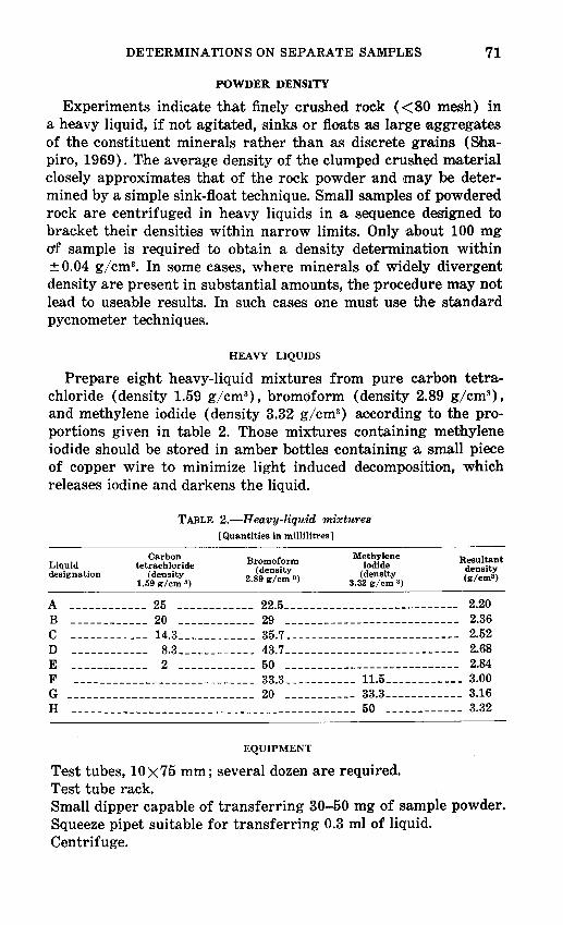
DETERMINATIONS ON SEPARATE SAMPLES 71
POWDER DENSITY
Experiments indicate that finely crushed rook ( < 80 mesh) in a heavy liquid, if not agitated, sinks or floats as large aggregates of the constituent minerals r.ather than as discrete grains (Shapiro, 1969). The average density o:f the clumped crushed material closely approximates that of the rock powder ·and ,may be determined by a simple sink-float technique. Small samples of powdered rock are centrifuged in heavy liquids in a sequence designed to bracket their densities within narrow limits. Only about 100 mg ctf sample is required to obtain a density determination within ± 0.04 g/cm3
• In some cas·es, where minerals of widely divergent density are present in substantial a·mounts, the procedure may not lead to useable results. In such cases one must use the standard pycnometer techniques.
HEAVY LIQUIDS
Prepare eight heavy-liquid mixtures from pure carbon tetrachloride (density 1.59 g/cm3
), bromoform (density 2.89 g/cm3),
and methylene iodide (density 3.32 g/cm3) according to the pro
portions given in table 2. Those :mixtures containing methylene iodide should be stored in amber bottles containing a small piece of copper wire to minimize light induced decomposition, which releases iodine and darkens the liquid.
Liquid designation
TABLE 2.-H eavy-liquid mixtures [Quantities in millilitres 1
Carbon tetrachloride
(density 1.59 g/cm 3)
Bromoform (density
2.89 gjcm 3 )
Methylene iodide
(density 3.32 gjcm 3 )
Resultant density (gjcm3 )
A ------------ 25 ------------ 22.5---------------------------- 2.20 B ------------ 20 ------------ 29 ·--------------------------- 2.36 c ------------ 14.3 ____________ 35.7.___________________________ 2.52 D _ _ _ _ _ _ ___ __ _ 8.3_ _ __ _ _ _ _ _ __ _ 43.7 ·- ____________ -------------- 2.68
E ------------ 2 ------------ 50 ·------- -------------------- 2.84 F ---------------------------- 33~----------- 11.5 ____________ 3.00 G ----------------------------- 20 ·----------- 33.3 ____________ 3.16
H -------------------------------------------- 50 ------------ ~32
EQUIPMENT
Test tubes, 10X75 mm; several dozen are required. Test tube rack. Small dipper capable of transferring 30-50 mg of sample powder. Squeeze pipet suitable for transferring 0.3 ml of liquid. Centrifuge.
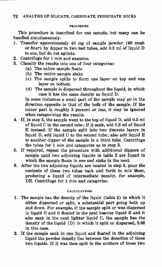
72 ANALYSIS OF SILICATE, CARBONATE, PHOSPHATE ROCKS
PROCEDURE
This procedure is described for one sample, but many can be · handled simultaneously. 1. Transfer approximately 40 mg of sample powder ( 80 mesh
or finer) by dipper to two test tubes, add 0.3 rn1 of liquid D to one, but do net agitate.
2. Centrifuge for 1 min and examine. 3. Classify the results into one of four categories :
(a) The entire sample floats (b) The entire sample sinks (c) The sample splits to form one layer on top and on~
layer on bottom. (d) The sample is dispersed throughout the liquid, in which
oose it has the same density as liquid D. In some instances a sm!all part of the sample may go in the direction opposite to that of the bulk of the sample. If the minor part is roughly 5 percent or less, it may be ignored when categorizing the results.
4. If, in step 3, the sample went to the top of liquid D, add 0.3 ml of liquid C to the second tube; if it sank, add 0.3 rn1 of liquid E instead. If the sample split into two discrete layers in liquid D, add liquid C to the second tube; also add liquid E to another dipper of the sample in a third tube. Centrifuge the tubes for 1 min and categorize as in step 3.
5. If required, repeat the procedure with additional dippers of sample until two adjoining liquids in table 2 are found in which the sample floats in one and sinks in the next.
6. After the two adjoining liquids are located in step 5, pour the contents of these two tubes back and forth to mix them, producing a liquid of intermediate density, for example, DE. Centrifuge for 1 min and categorize.
CALCULATIONS
1. The sample has the density of the liquid (table 2) in which it either dispersed or split, a ·substantial part going both up and down. For example, if the sample split or was dispersed in liquid D and it floated in the next heavier liquid E and it also sank in the next lighter liquid C, the sample has the density of the liquid (D) in which it split or dispersed, 2.68 in this case.
2. If the sample s·ank in one liquid and floated in the adjoining liquid the powder density lies between the densities of these two liquids. If it was then split in the mixture of these two
DETERMINATIONS ON SEPARATE SAMPLES 73
liquids it corresponds to the density of the average of their densities, for example, for CD the density would be 2.60. If the sample sank in the mixture CD, it is considered to be heavier by 0.04 than this average, that is 2.64; if it floated in CD it is taken to be less than this average by 0.04, that is, 2.56.
3. If the sa·mple forms two discrete layers in two adjoining liquids, as listed in table 2, or if it sinks in the heaviest liquid available, the density obviously cannot be deter·mined by this procedure.
BULK DENSITY
Bulk density is usually determined on a 10- to 40-g rock fragment. The procedure is a minor v·ariation of what might be c·alled the eureka method of Archimedes, which is based on buoyancy in water. Generally, in such procedures the rock is weighed when dry and then again when submerged in water. Most rocks absorb water into pores and crevices and, on being submerged, show a constantly changing weight. It is common procedure to coat the rock fragment with wax to prevent this from occurring; however, the process of coating and removal of the wax is time consuming. In the procedure described, the rock is saturated with water and weighed. A correction is made to take the absorbed water into account. When the water-saturated rock is weighed after its removal from water, it loses weight at the rate of several milligrams per minute. A weighing can easHy be made however in 1-2 min and a loss of 10 mg on a 1 O:..g sample represents an error of 0.1 percent relative in the density. If the density is obtained to within 0.5 percent relative, that is, with ± 0.015 absolute for a rock having a density of 3.00, it is satisf·actory for most purposes.
APPARATUS
600 ml beaker filled with water. Metal bridge consisting of a piece of sheet metal 62 mm wide, bent
to form a bridge over the balance pan to support the beaker so that a sample suspended from the balance hangs submerged in the beaker of water.
Thin piece of wire long enough to hook onto the ·ba.l·ance beam and to support the piece of rock when fully submerged.
PROCEDURE
1. Submerge each rock sample in a beaker of water for about 1 hr or longer.
74 ANALYSIS OF SILICATE, CARBONATE, PHOSPHATE ROCKS
2. One at a time, hook the thin wire around each rock and hang it from the balance beam 'SO that it is fully submerged in the beaker of water. When the balance beam is released the balance should be able to come to equilibrium. If the rock is still absorbing water at a rate in excess of about 2 mg/min, the rock ·should be replaced in the original beaker of water and allowed additional time to absorb water. Such a rock is very porous. If the balance is at or near equilibrium, the most common condition, record the weight.
3. Carefully remove the rock from the water and the wire from the rock, so as not to fragment it. Cover the rock com.pletely with a dry tissue. Gently press the tissue over the entire surface of the rock. Remove the tissue and set the rock near the balance.
4. Remove the beaker ·and bridge from the balance case and place the rock on the balance pan. Weigh the wet rock as rapidly as possible recording the maximum weight. The rock will lose weight constantly at the r·ate of several miligrams or even more per minute, depending on its porosity. The time between the removal of the tissue and the observed weight should be no more than about 1-2 min.
5. Air-dry the rock overnight at room temperature. 6. Weigh the dry rock. 7. Obtain the wire weight when suspended from the balance and
hanging in the water as when in use.
CALCULATIONS
Use the following equation to obtain bulk density : Dry weight (after setting overnight)
bulk density. (Wet weight)
- (underwater weight+ wire weight)
REFERENCES CITED
Bandemer, S. L., and Schaible, P. J., 1944, Determination of iron: Indus. ~nd Eng. Chemistry, Anal. ed., v. 16, p. 317-319.
Bernas, Bedrich, 1968, A new method for decomposition and comprehensive analysis of silicates by atomic absorption spectrophotometry: Anal. Chemistry, v. 40, p. 1682-1686.
Biedermann, W., and Schwarzenbach, G., 1948, Complexons XI. The complexometric titration of alkaline earths and some other metals with eriochrome black T: Chimia, v. 2, p. 56.
Bunting, W. E., 1944, The determination of soluble silica in very low concentrations: Indus. and Eng. Chemistry, Anal. ed., v. 16, p. 612-615.

REFERENCES CITED 75
Dinnin, J. 1., 1959, Rapid analysis of chromite and chrome ore: U.S. Geol. Survey Bull. 1084-B, 68 p.
--- 1960, Releasing effects in flame photometry: Anal. Chemistry, v. 32, p. 1475.
Fairbairn, H. W., and others, 1951, A cooperative investigation of precision and accuracy in chemical, spectrochemical, and modal analysis of silicate rocks: U.S. Geol. Survey Bull. 980, 71 p.
Goldich, S. S., Ingamells, C. 0., and Thaemlitz, D., 1959, The chemical composition of Minnesota Lake marl-comparison of rapid and conventional chemical methods: Econ. Geology, v. 54, p. 285-3QO.
Grimaldi, F. S., Shapiro, Leonard, and Schnepfe, Marian, 1966, Determination of carbon dioxide in limestone and dolomite by acid-base titration, in Geological Survey Research 1966: U.S. Geol. Survey Prof. Paper 550-B, p. B186-B188.
Hillebrand, W. F., Lundell, G. E. F., Bright, H. A., and Hoffman, J. 1., 1953, Applied inorganic analysis: 2d ed., New York, John Wiley and Sons, p. 447.
Ingamells, C. 0., 1964, Rapid chemical analysis of silicate rocks: Talanta, v. 11' p. 665-666.
--- 1966, Absorptiometric methods in silicate analysis: Anal. Chemistry, v. 38, p. 1228-1234.
Kitson, R. E., and Mellon, M. G., 1944, Colorimetric determination of phosphorous as molybdovanadophosphoric acid: Indus. and Eng. Chemistry, Anal. ed., v. 16, p. 379-383.
Langmyhr, F. J., and Paus, P. E., 1968, The analysis of inorganic siliceous materials by atomic absorption spectrophotometry and the hydrofluoric acid decomposition technique-Part I, The analysis of silicate rocks: Anal. Chimica Acta, v. 43, p. 397-408.
May. Irving, and Rowe, J. J., 1965, Solution of rocks and refractory minerals by acids at high temperatures and pressures-Determination of silica after decomposition with hydrofluoric acid: Anal. Chim. Acta, v. 33 p. 648-654.
Parker, C. A., and Goddard, A. P., 1950, The reaction of aluminum ions with alizarin-3-sulphonate, with particular reference to the effect of calcium ions: Anal. Chimica Acta, v. 4, p. 517-536.
Pribil, R., 1953, Screening of aluminum, iron, and manganese in titrations with murexide as indicator: Chern. Listy, v. 47, p. 1333-1337.
Sarver, L. A., 1927, The determination of ferrous iron in silicates: Am. Chern. Soc. Jour., v. 49, p. 1472-1477.
Shapiro, Leonard, 1959, Design of Teflon vessel for decomposition of rock samples: Chemist-Analyst, v. 48, p. 46.
--- 1967a, Rapid analysis of rocks and minerals by a single-solution method, in Geological Survey Research 1967: U.S. Geol. Survey Prof. Paper 575-B, p. B187-B191.
---1967b, A simple and rapid indirect determination of fluorine in minerals and rocks, in Geological Survey Research 1967: U.S. Geol. Survey Prof. Paper 575-D, p. D233-D235.
--- 1969, Rapid determination of powder density of rocks by a sink-float technique, in Geological Survey Research 1969: U.S. Geol. Survey Prof. Paper 650-B, p. B140-B142.
---1971, Rapid scanning technique for low levels of C02 in silicate roc'ks, in Geological Survey Research 1971: U.S. Geol. Survey Prof. Paper 750-B, p. B161-B162.

76 ANALYSIS OF SILICATE, CARBONATE, PHOSPHATE ROCKS
--- 1973, Rapid determination of sulfur in rocks: U.S. Geol. Survey Jour. Research, v. 1, no. 1, p. 81-84.
--.--1974, Spectrophotometric determination of silica at high concentrations using fluoride as a depolymerizer: U.S. Geol. Survey Jour. Research, v. 2, no. 3, p. 357-360.
Shapiro, Leonard, and Brannock, W. W., 1952, Rapid analysis of silicate rocks: U.S. Geol. Survey Circ. 165, 17 p.
---1955a, Rapid determination of C02 in silicate rocks: Anal. Chemistry, v. 27, p. 1796-97.
---1955b, Rapid determination of water in silicate rocks: Anal. Chemistry, v. 27' p. 560-564.
---1956, Rapid analysis of silicate rocks: U.S. Geol. Survey Bull. 1036-C, p. 19-56.
--- 1962, Rapid analysis of silicate, carbonate and phosphate rocks: U.S. Geol. Survey Bull. 1144-A, 56 p.
Shapiro, Leonard, and Massoni, C. J., 1968, Automatic sample changer for atomic absorption spectrophotometry, in Geological Survey Research 1968: U.S. Geol. Survey Prof. Paper 600-B, p. 126-129.
---1972, An automated spectrophotometer, in Geological Survey Research 1972: U.S. Geol. Survey Prof. Paper 800-B, p. 137-140.
Shapiro, Leonard, and Rosenbaum, Fred, 1962, A sequential heating device for FeO determinations, in Geological Survey Research 1962: U.S. Geol. Survey Prof. Paper 450-C, p. C102-Cl03.
Stevens, R. E., and others, 1960, Second report on a cooperative investigation of the composition of two silicate rocks: U.S. Geol. Survey Bull. 1113, 126 p.
Suhr, N. H., and Ingamells, C. 0., 1966, Solution technique for analysis of silicates: Anal. Chemistry, v. 38, p. 730-734.
Yoe, J. H., and Armstrong, A. R., 1947, Colorimetric determination of titanium with disodium-1, 2-dihydroxybenzene-3, 5-disulfonate: Anal. Chemistry, v. 19, p. 100-102.
*U.S. GOVERNMENT PRINTING OFFICE: 1975 0-211-317/39