ransformers ensión -...
40
Low Voltage Current Transformers Transformadores De Corriente De Baja Tensión
Transcript of ransformers ensión -...

Low
Volt
age C
urre
nt
Tran
sfor
mers
Tran
sfor
mado
res D
e
Corr
iente
De B
aja T
ensió
n
LOW VOLTAGE CURRENT TRANSFORMERSTransformadores De Corriente De Baja
Tensión

11
237www.sigmaelektrik.com
Low Voltage Current Transformers Transformadores De Corriente De Baja Tensión
Content
General Information . . . . . . . . . . . . . . . . . . . . . . . . . . . .237Technical Specifi cations . . . . . . . . . . . . . . . . . . . . . . . .237Importance Of Not Leaving Current Transformer Secondary Port Open . . . . . . . . . . . . . . . . . . . . . . . . . . .238Importance Of Earthing Of Current Transformer Secondary Port And Its Connection Type . . . . . . . . . .239Determining The Power Of Current Transformers . . .239Rated Power Of Some Devices Connected To Current Transformers (VA) . . . . . . . . . . . . . . . . . . . . . .240Some Important Terms Used In Selection Of Current Transformers . . . . . . . . . . . . . . . . . . . . . . . . . . .240
Primary Rated Current . . . . . . . . . . . . . . . . . . . . . . . . . . . . . . . . 240Saturation Coeffi cient . . . . . . . . . . . . . . . . . . . . . . . . . . . . . . . . . 240Rated Thermal Current . . . . . . . . . . . . . . . . . . . . . . . . . . . . . . . . 240Rated Dynamic Current . . . . . . . . . . . . . . . . . . . . . . . . . . . . . . . . 241Limits Of Current Error And Phase Displacement (Pursuant To IEC/EN 61869-2, Classes 0.1 - 0.2 - 0.2s - 0.5 - 0.5s - 1) . . . 241Limits Of Current Error And Phase Displacement (for The accuracy classes 5P And 10P) . . . . . . . . . . . . . . . . . . 241
Current Carrying Capacity Of Busbars . . . . . . . . . . . . .242Current Carrying Capacity Of LV Cables . . . . . . . . . . .242Main Measurements . . . . . . . . . . . . . . . . . . . . . . . . . . .242Fixing And Installation Details . . . . . . . . . . . . . . . . . . .243Installation Of Current Transformers To Din Rail . . .243Structure Of Current Transformers . . . . . . . . . . . . . . .243S20-S20L Series Current Transformer . . . . . . . . . . . .244
Technical Specifi cations . . . . . . . . . . . . . . . . . . . . . . . . . . . . . . . 244Dimensions . . . . . . . . . . . . . . . . . . . . . . . . . . . . . . . . . . . . . . . . . . 244
S20M-S20ML Series Current Transformer . . . . . . . . .246Technical Specifi cations . . . . . . . . . . . . . . . . . . . . . . . . . . . . . . . 246Dimensions . . . . . . . . . . . . . . . . . . . . . . . . . . . . . . . . . . . . . . . . . . 246
S25B Series Bar Type Current Transformer . . . . . . . .248Technical Specifi cations . . . . . . . . . . . . . . . . . . . . . . . . . . . . . . . 248Dimensions . . . . . . . . . . . . . . . . . . . . . . . . . . . . . . . . . . . . . . . . . . 248
S30-S30L Series Current Transformer . . . . . . . . . . . .250Technical Specifi cations . . . . . . . . . . . . . . . . . . . . . . . . . . . . . . . 250Dimensions . . . . . . . . . . . . . . . . . . . . . . . . . . . . . . . . . . . . . . . . . . 250
S30M-S30ML Series Current Transformer . . . . . . . . .252Dimensions . . . . . . . . . . . . . . . . . . . . . . . . . . . . . . . . . . . . . . . . . . 252
S40 Series Current Transformer . . . . . . . . . . . . . . . . . .254Technical Specifi cations . . . . . . . . . . . . . . . . . . . . . . . . . . . . . . . 254Dimensions . . . . . . . . . . . . . . . . . . . . . . . . . . . . . . . . . . . . . . . . . . 254
S50 Series Current Transformer . . . . . . . . . . . . . . . . . .256Technical Specifi cations . . . . . . . . . . . . . . . . . . . . . . . . . . . . . . . 256Dimensions . . . . . . . . . . . . . . . . . . . . . . . . . . . . . . . . . . . . . . . . . . 256
S60 Series Current Transformer . . . . . . . . . . . . . . . . . .258Technical Specifi cations . . . . . . . . . . . . . . . . . . . . . . . . . . . . . . . 258Dimensions . . . . . . . . . . . . . . . . . . . . . . . . . . . . . . . . . . . . . . . . . . 258
S60A Series Current Transformer (Split Core Current Transformer) . . . . . . . . . . . . . . . . . . . . . . . . . . . . . . . . . .260
Technical Specifi cations . . . . . . . . . . . . . . . . . . . . . . . . . . . . . . . 260Dimensions . . . . . . . . . . . . . . . . . . . . . . . . . . . . . . . . . . . . . . . . . . 260
Índice
Información General . . . . . . . . . . . . . . . . . . . . . . . . . . . . . . 237
Especifi caciones Técnicas . . . . . . . . . . . . . . . . . . . . . . . . . 237
Importancia De Que No Se Quede Abierto El Extremo Secundario Del Transformador De Corriente. . . . . . . . . 238
Esquema De Conexión E Importancia De La Toma De Tierra Del Extremo Del Secundario Y Del Cuerpo Del Transformador De Corriente . . . . . . . . . . . . . . . . . . . . . . . 239
Determinación De La Potencia De Los Transformadores De Corriente . . . . . . . . . . . . . . . . . . . . . 239
Potencia Rated (VA) De Algunos Dispositivos Conectados A Los Transformadores De Corriente . . . . 240
Algunos Términos Importantes Que Se Utilizan En La Elección De Transformadores De Corriente . . . . . . . . . . 240
Corriente Nominal Primaria . . . . . . . . . . . . . . . . . . . . . . . . . . . . . . . . 240Factor De Saturación . . . . . . . . . . . . . . . . . . . . . . . . . . . . . . . . . . . . . 240Corriente Rated Térmica . . . . . . . . . . . . . . . . . . . . . . . . . . . . . . . . . . . 240Corriente Rated Dinámica . . . . . . . . . . . . . . . . . . . . . . . . . . . . . . . . . 241Límites Del Desplazamiento De Fase Y Fallo De Corriente (Clases 0.1 - 0.2 - 0.2s - 0.5 - 0.5s - 1 De Acuerdo Con IEC/EN 61869-2) . . . . . . . . . . . . . . . . . . . . . . . . . . . . . . . . . . . . . . . . . . . . . . . . 241Límites Del Desplazamiento De Fase Y Fallo De Corriente (para Las clases 5P Y 10P) . . . . . . . . . . . . . . . . . . . . . . . . . . . . . . . . 241
Capacidad De Transporte De Corriente De las Barras. . . . . . . . . . . . . . . . . . . . . . . . . . . . . . . . . . . . . 242
Capacidad De Transporte De Energía De Los Cables LV . . . . . . . . . . . . . . . . . . . . . . . . . . . . . . . . . 242
Medidas Principales . . . . . . . . . . . . . . . . . . . . . . . . . . . . . . 242
Fijación Al Carril DIN . . . . . . . . . . . . . . . . . . . . . . . . . . . . . . 243
Montaje Del Transformador De Energía Al Carril DIN . 243
Estructura Del Transformador De Corriente . . . . . . . . . 243
S20-S20L Transformador De Corriente . . . . . . . . . . . . . 245Características Técnicas . . . . . . . . . . . . . . . . . . . . . . . . . . . . . . . . . . 245Dimensiones . . . . . . . . . . . . . . . . . . . . . . . . . . . . . . . . . . . . . . . . . . . . . 245
S20M-S20ML Transformador De Corriente . . . . . . . . . . 247Características Técnicas . . . . . . . . . . . . . . . . . . . . . . . . . . . . . . . . . . 247Dimensiones . . . . . . . . . . . . . . . . . . . . . . . . . . . . . . . . . . . . . . . . . . . . . 247
S25B Transformador De Corriente De Tipo Barra . . . . 249Características Técnicas . . . . . . . . . . . . . . . . . . . . . . . . . . . . . . . . . . 249Dimensiones . . . . . . . . . . . . . . . . . . . . . . . . . . . . . . . . . . . . . . . . . . . . . 249
S30-S30L Transformador De Corriente . . . . . . . . . . . . . 251Características Técnicas . . . . . . . . . . . . . . . . . . . . . . . . . . . . . . . . . . 251Dimensiones . . . . . . . . . . . . . . . . . . . . . . . . . . . . . . . . . . . . . . . . . . . . . 251
S30M-S30ML Transformador De Corriente . . . . . . . . . . 253Características Técnicas . . . . . . . . . . . . . . . . . . . . . . . . . . . . . . . . . . 253Dimensiones . . . . . . . . . . . . . . . . . . . . . . . . . . . . . . . . . . . . . . . . . . . . . 253
S40 Transformador De Corriente . . . . . . . . . . . . . . . . . . . 255Características Técnicas . . . . . . . . . . . . . . . . . . . . . . . . . . . . . . . . . . 255Dimensiones . . . . . . . . . . . . . . . . . . . . . . . . . . . . . . . . . . . . . . . . . . . . . 255
S50 Transformador De Corriente . . . . . . . . . . . . . . . . . . . 257Características Técnicas . . . . . . . . . . . . . . . . . . . . . . . . . . . . . . . . . . 257Dimensiones . . . . . . . . . . . . . . . . . . . . . . . . . . . . . . . . . . . . . . . . . . . . . 257
11
238 www.sigmaelektrik.com
Low Voltage Current Transformers Transformadores De Corriente De Baja Tensión
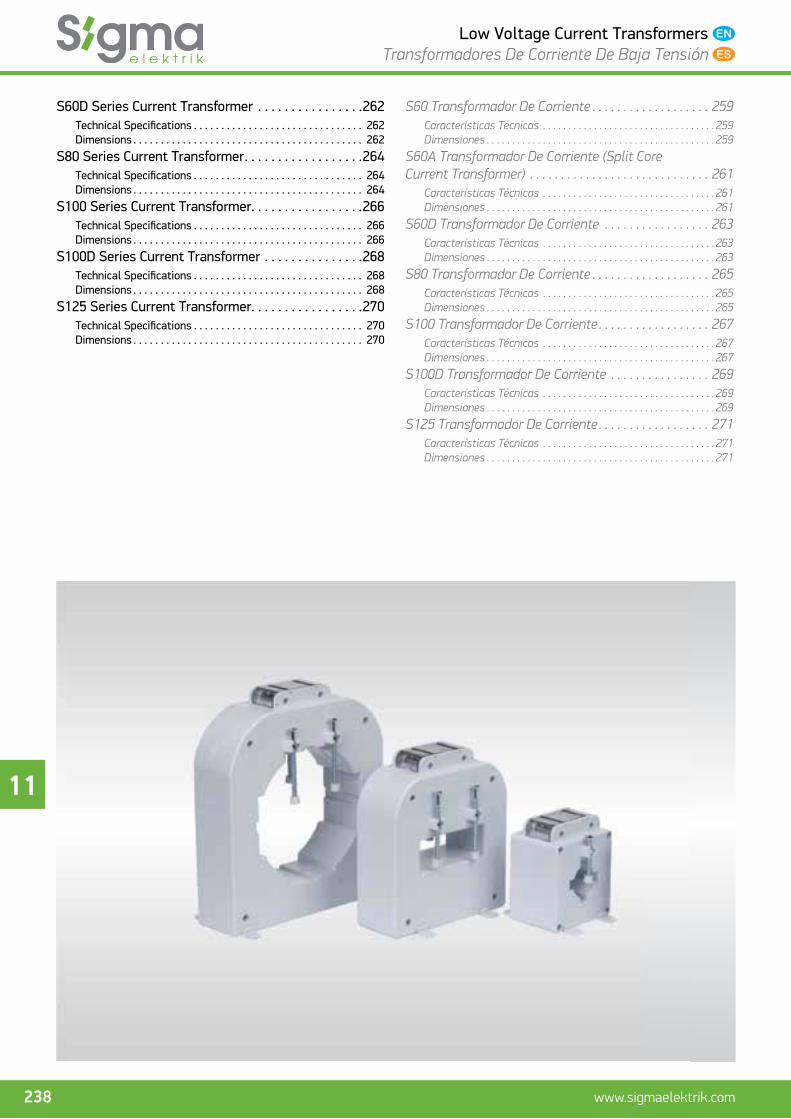
S60D Series Current Transformer . . . . . . . . . . . . . . . .262Technical Specifi cations . . . . . . . . . . . . . . . . . . . . . . . . . . . . . . . 262Dimensions . . . . . . . . . . . . . . . . . . . . . . . . . . . . . . . . . . . . . . . . . . 262
S80 Series Current Transformer . . . . . . . . . . . . . . . . . .264Technical Specifi cations . . . . . . . . . . . . . . . . . . . . . . . . . . . . . . . 264Dimensions . . . . . . . . . . . . . . . . . . . . . . . . . . . . . . . . . . . . . . . . . . 264
S100 Series Current Transformer. . . . . . . . . . . . . . . . .266Technical Specifi cations . . . . . . . . . . . . . . . . . . . . . . . . . . . . . . . 266Dimensions . . . . . . . . . . . . . . . . . . . . . . . . . . . . . . . . . . . . . . . . . . 266
S100D Series Current Transformer . . . . . . . . . . . . . . .268Technical Specifi cations . . . . . . . . . . . . . . . . . . . . . . . . . . . . . . . 268Dimensions . . . . . . . . . . . . . . . . . . . . . . . . . . . . . . . . . . . . . . . . . . 268
S125 Series Current Transformer. . . . . . . . . . . . . . . . .270Technical Specifi cations . . . . . . . . . . . . . . . . . . . . . . . . . . . . . . . 270Dimensions . . . . . . . . . . . . . . . . . . . . . . . . . . . . . . . . . . . . . . . . . . 270
S60 Transformador De Corriente . . . . . . . . . . . . . . . . . . . 259Características Técnicas . . . . . . . . . . . . . . . . . . . . . . . . . . . . . . . . . . 259Dimensiones . . . . . . . . . . . . . . . . . . . . . . . . . . . . . . . . . . . . . . . . . . . . . 259
S60A Transformador De Corriente (Split Core Current Transformer) . . . . . . . . . . . . . . . . . . . . . . . . . . . . . 261
Características Técnicas . . . . . . . . . . . . . . . . . . . . . . . . . . . . . . . . . . 261Dimensiones . . . . . . . . . . . . . . . . . . . . . . . . . . . . . . . . . . . . . . . . . . . . . 261
S60D Transformador De Corriente . . . . . . . . . . . . . . . . . 263Características Técnicas . . . . . . . . . . . . . . . . . . . . . . . . . . . . . . . . . . 263Dimensiones . . . . . . . . . . . . . . . . . . . . . . . . . . . . . . . . . . . . . . . . . . . . . 263
S80 Transformador De Corriente . . . . . . . . . . . . . . . . . . . 265Características Técnicas . . . . . . . . . . . . . . . . . . . . . . . . . . . . . . . . . . 265Dimensiones . . . . . . . . . . . . . . . . . . . . . . . . . . . . . . . . . . . . . . . . . . . . . 265
S100 Transformador De Corriente . . . . . . . . . . . . . . . . . . 267Características Técnicas . . . . . . . . . . . . . . . . . . . . . . . . . . . . . . . . . . 267Dimensiones . . . . . . . . . . . . . . . . . . . . . . . . . . . . . . . . . . . . . . . . . . . . . 267
S100D Transformador De Corriente . . . . . . . . . . . . . . . . 269Características Técnicas . . . . . . . . . . . . . . . . . . . . . . . . . . . . . . . . . . 269Dimensiones . . . . . . . . . . . . . . . . . . . . . . . . . . . . . . . . . . . . . . . . . . . . . 269
S125 Transformador De Corriente . . . . . . . . . . . . . . . . . . 271Características Técnicas . . . . . . . . . . . . . . . . . . . . . . . . . . . . . . . . . . 271Dimensiones . . . . . . . . . . . . . . . . . . . . . . . . . . . . . . . . . . . . . . . . . . . . . 271

11
239www.sigmaelektrik.com
Low Voltage Current Transformers Transformadores De Corriente De Baja Tensión
General InformationCurrent transformer is used to supply acceptors (e.g., 1A, 5A) that operate in low rated current to be used for measurement and protection purposes (e.g., > 10 A) in the systems where high rated current pass through.
Internal resistances of the acceptors connected to current transformers are very low. Secondary ports of current trans-formers should never be lest empty. If the secondary of a cur-rent transformer, primary of which was connected to the net-work is lest without load, magnetic fl ux, which is in the reverse direction of primary coil fl ux of secondary circuit disappears. This results in induction of high voltages in the secondary, directly proportional to number of secondary coil and impair-ment of coil insulation, which is connected to this. Besides, iron loss in the core increases due to high magnetic fl ux and heats the core extremely. If it is required to open secondary ports due to repair or change the acceptor in the secondary whto current passes through the primary, it is essential to short circuit the secondary. Otherwise, the voltage to increase in the secondary may endanger the operator
Technical Specifi cationsFollowing formula may be utilized to determine the power of current transformer. The most important issue here is that the power to be determined should not be more than the full load of transformer power to be requested and that it isc’t be less than the quarter load. In the contrary case, requested trans-former may not contribute to the requirement completely; incorrect measurements or false protection may lead to forma-tion of signals.
Power of Secondary (PS) = Power of Acceptor (PA) + Connection cable losses (PK) + Contact losses (PT)
PT = It may be taken around 0,5 VA based on the number of connections to be performed between secondary acceptor.
All magnetic cores are controlled and classifi ed before the production.Antes de la fabricación todos los núcleos magné-ticos son sometidos a un control de calidad y se clasifi can.
Nickel plated connection terminals provid-ing easy installation optionTerminales de conexiones revestidos de níquel que permiten un montaje fácil
“Made in Turkey” inscription which indicates that product is produced in TurkeyEscrito “Made in Turkey” que muestra que el producto ha sido fabricado en Turquía.
Moulded, non-erasable, nondeletable conversion ratio on the coverRatio se conversión sobre el cuerpo que sale del molde y que no se puede borrar ni rayarse.
Sealed supply upon requestZona con sello (opcional)
Insulation strength between primary-secondary, which is requested to be 3 kV in IEC/EN 61869-2 is 3kV in Sigma current transformers.La resistencia de aislamiento entre primario y secundario requerido como 3kV por la normativa IEC/EN 61869-2 es de 5kW en los transformadores de corriente Sigma
Fire and fl ame resistant thermoplastic materialMaterial termoplásticos resistente al fuego y las llamas.
Accuracy class of each current transformer, production of which is completed is controlled with Omicron branded test instrument at Sigma Electric.Todos los transformadores fabricados por Sigma Elektrik son puestos a prueba con un aparato de test de marca Omicron de clase de precisión.
Información GeneralEl transformador de corriente se utilizar para alimentar los recep-tores (por ejemplo: 1A, 5A) que funcionan en la corriente nominal baja que se utilizará para proteger y medir en los sistemas por los que pasa una alta corriente nominal (por ejemplo: >10A).
La resistencia de los receptores que se conectan a los transforma-dores de corriente son muy pequeños. Los extremos secundarios de los transformadores de corriente no deben de dejarse vacíos en ningún momento. Si el secundario de un transformador de corriente conectado a una red primaria se queda sin carga, desaparece el fl ujo magnético que se encuentra en dirección contraria al fl ujo bobinado primario del circuito secundarios. Esta situación en el secundario puede causar que se estropee el aislamiento bobinado conectado a él y que se induzcan tensiones altas de forma direc-tamente proporcional al número de bobinas secundarias. Además, el núcleo pierde hierro, calentándose demasiado como consecuen-cia de que la corriente magnética sea alta. Si hace falta abrir los extremos del secundario debido a una reparación o cambio en el receptor del secundario cuando pasar corriente del primario, es necesario cortocircuitar el secundario. De lo contrario, la tensión que subirá en el secundario puede poner en peligro al operador de corriente.
Especifi caciones TécnicasLa fórmula que aparece a continuación puede servir para determi-nar la potencia del transformador de corriente. La cuestión más importante es que la potencia detectada no sea mayor que la carga total de la potencia del transformador que se va a encargar, ni menor que un cuarto de su carga. De lo contrario, el transforma-dor adquirido podría no responder totalmente a sus necesidades y puede causar que se formen señales de protección o mediciones erróneas.
Potencia Secundaria (PS) = Fuerza del receptor (PA) + Pérdidas del cable de conexión (PK) + Pérdidas de contacto (PT)
PT= Puede tomarse alrededor de 0.5VA de acuerdo con las cantida-des de conexiones que se realizarán entre el receptor secundario.

11
240 www.sigmaelektrik.com
Low Voltage Current Transformers Transformadores De Corriente De Baja Tensión
Standard IEC/EN 61869-2 Estándar
Rated operating voltage (Un) 720V Tensión nominal de funcionamiento (Un)
Rated frequency 50/60Hz Frecuencia proporcional
Ambient temperature -20/75°C Temperatura ambiente
Storage temperature -50/80°C Temperatura de carga
Operating humidity Relative humidity up to 95% Hasta 95% de humedad relativa
Humedad de funcionamiento
Rated thermal continious current 1.2xIn Corriente nominal termal constante
Rated short-time thermal current (Ith) 60xln / 1 sc. - 100xln / 1 sc. Corriente nominal térmica de corto plazo.
Rated dynamic current (Idyn) 2. 5 x Ith / 1 sc Corriente nominal térmica breve (ldyn)
Rated power - frequency withstand voltage 3kV eff . (50 Hz) /1 min. Tensión de resistencia nominal de potencia y frecuencia
Thermal class of insulation E (120°C max.) Clase de temperatura de aislamieto
Casing Non-fl ammable, self-extinguishing, glass fi bre supported PA6 PA6 ignífuro, apaga los incendios por sí mismo, fabricado de fi bra
de cristal
Caja
Degree of protection IP20 Grado de protección
Instrument security factor (FS) 5 Factor de seguridad del instrumental (FS)
Secondary terminals Brass nickel plated M5 screw coverRevestimiento de tornillos de Níquel y Bronce m5
Terminales secundarias
Recommended tightening torque 2 Nm (for secondary terminals)2 Nm (para las terminales secundarias)
Par de apriete recomendado
Accuracy class Measurement; 0.2, 0.2s, 0.5, 0.5s, 1, 3Medición: 0.2, 0.2s, 0.5, 0.5s,1, 3
Tipo de precisión
Burden 1 to 30VA / entre 1 y 30VA Carga
Rated primary current Up to 5000A / hasta 5000A Corriente nominal primaria
Rated secondary current 1 to 5A / entre 1 y 5A Corriente nominal secundaria
Sigma low voltage current transformers transform primary cur-rents from 20 A to 5000 A into secondary currents at a rate of 1 A or 5 A at requested power and accuracy rate. Sigma low volt-age current transformers are produces in 9 diff erent lengths for diff erent bar measurements in compliance with IEC/EN 61869-2, they may be produced as sealed by ministry of industry and trade when requested.
Importance Of Not Leaving Current Transformer Secondary Port OpenAs the internal resistances of elements, connected to the sec-ondary of current transformer are very low, current transform-ers operate in case of short circuit. If the secondary of a current transformer, primary of which was connected to the circuit is lest without load or open, magnetic fl ux, which is in the reverse direction of primary coil fl ux of secondary coil, disappears. Based on the current passing through primaries, magnetic current in the core of the transformer increases signifi cantly. As a result of increase in magnetic current, transformer core is saturated with magnetizing current and there occurs some thousand volt voltages in secondary ports. Besides, iron loss in the core increases due to high magnetic current and heats the core extremely and transformer is impaired. In order to prevent such dangers, secondary port of current transformer is short circuited even if it is not used.
Los transformadores de corriente de baja tensión Signa transfor-man las corrientes primarias desde 20A hasta 5000A, en valores de precisión y fuerza deseados, a corriente secundaria de valor 1A hasta 5A. Los transformadores de corriente de baja tensión se fabrican en 9 tamaños diferentes para distintos tipos de barra de acuerdo con la normativa IEC/EN 61869-2. Si así se desea, se pue-den fabricar con el sello del Ministerio de Industria y Comercio.
Importancia De Que No Se Quede Abierto El Extremo Secundario Del Transformador De CorrienteDebido a que la resistencia interior de los componentes que conec-tan al secundario de transformador de corriente los transformado-res de corriente funcionan cortocircuitados. Si se dejan los extre-mos del secundario de un transformador de corriente conectado a un circuito primario sin carga, desaparece el fl ujo magnético existente en dirección inversa al fl ujo del bobinado primario del bobinado secundario. Según la corriente que pase por el primario, aumenta de forma importante la corriente magnética existente en el núcleo del transformador. Como consecuencia del aumento de la corriente magnética, el núcleo se llena de corriente de magne-tización y se produce una corriente de varios miles de voltios en los extremos del secundario. Además, a causa de que la corriente magnética sea alta, aumentan las pérdidas de hierro del núcleo, que se calienta demasiado, y se daña el transformador. Para pre-venir este peligro el extremo secundario del transformador de corriente se cortocircuita aunque no se vaya a utilizar.

11
241www.sigmaelektrik.com
Low Voltage Current Transformers Transformadores De Corriente De Baja Tensión
Importance Of Earthing Of Current Transformer Secondary Port And Its Connection TypeIt is essential to earth one port of secondary coils of current transformers. The reason for this is that primary circuit volt-age creates a closed circuit from neutral point of power trans-former with the help of grounded secondary port in case of a short circuit arising between the primary and secondary coil of transformer.
In case of failure to ground secondary coil port of current trans-former, primary circuit voltage is applied to measurement and protection circuits, which are connected to secondary in case of such failure. Thus, the insulation of measurement and protec-tion elements on this circuit is punctured. At the same time, it results in a life-threatening situation for the employed person-nel.
Determining The Power Of Current TransformersFollowing formula can be used to determine the power of cur-rent transformer. The most important issue here is that the power, determined should not be more than the full load of transformer power to be requested and that it isc’t less than the quarter load. In the contrary case, requested transformer may not contribute to the requirement completely; incorrect measurements or false protection may lead to formation of signals.
PS = PA + PK + PT
PS : Power of secondary
PA : Power of load
PK : Connection cable losses
PT : Contact losses (may be taken as 0.5 VA)
Connection cable losses (PK)
PK= (Isc2x2l) / S x 56
Isc = Rated current of secondary
2l = The length of conductor between acceptor and secondary
S = Section of copper conductor (mm2)
56 = Specifi c conductivity of copper cable
Distance between current transformer and load
Distancia entre el transformador de corriente y la carga
Loss to be created by the cable, connected to secondary (PK) (VA)Perdida provocada por el cable que se conecta al secundario (PK) (VA)
** Adjacent formula may be used for the load to lose in conductor lengths other than the above table.
** Se puede utilizar la fórmula de al lado para la potencia que se perderá en la longitud de los con-ductores que no sean los de la tabla anterior.
2.5 mm2 4 mm2 6 mm2 10 mm2
1m 0.36 0.22 0.15 0.09
2m 0.71 0.45 0.3 0.18
3m 1.07 0.67 0.45 0.27
4m 1.43 0.89 0.6 0.36
5m 1.78 1.12 0.74 0.44
6m 2.14 1.34 0.89 0.54
7m 2.5 1.56 1.04 0.63
8m 2.86 1.79 1.19 0.71
9m 3.21 2.01 1.34 0.8
10m 3.57 2.24 1.49 0.89
Esquema De Conexión E Importancia De La Toma De Tierra Del Extremo Del Secundario Y Del Cuerpo Del Transformador De CorrienteEs necesario crear una toma de tierra para los bobinados secunda-rios de los transformadores de corriente. La causa de esto es que en un cortocircuito que se forma entre el bobinado secundario y el bobinado primario del transformador de corriente, la tensión del circuito primario genera un circuito cerrado desde el punto neutro del transformador de potencia con ayuda del extremo secundario con toma de tierra.
En caso de que no se le haga toma de tierra al extremo del bobi-nado secundario del transformador de corriente, en dicho error la tensión de circuito primario se impone a los circuitos de protección y medición conectados al secundario. Por lo tanto, se agujerea el aislamiento de estos elementos de protección y medida que están sobre este circuito. Al mismo tiempo, esto conforma también un serio peligro para la vida de los trabajadores.
Determinación De La Potencia De Los Transformadores De CorrienteLa fórmula expresada a continuación puede servir para determinar la potencia del transformador de corriente. La cuestión más impor-tante es que la potencia determinada no sea mayor que la carga de la potencia total del transformador encargado, ni sea menor que un cuarto de su carga. De lo contrario, puede da lugar a que se formen señales falsas de protección, así como mediciones falsas.
PS = PA + PK + PT
PS : Potencia secundaria
PA : Potencia receptora
PK : Pérdidas de conexión de cable
PT : Pérdidas de contacto (puede tomarse 0.5 VA)
Pérdida de cable de conexión (PK)
PK = (Isc2x2l) / S x 56
Isc = Corriente nominal de secundario
2l = Longitud del conductor entre el receptor y el secundario
S = Sección del conductor de cobre (mm2)
56 = Conducción específi ca del cable de cobre

11
242 www.sigmaelektrik.com
Low Voltage Current Transformers Transformadores De Corriente De Baja Tensión
Rated Power Of Some Devices Connected To Current Transformers (VA)
Acceptor Power (VA)
Ammeter 0.7 .... 1.5
Wattmeter 0.2 .... 5.0
CosØmeter 2.0 .... 6.0
Electricity meters 0.4 .... 1.0
Reactive power control relays 0.5 .... 1.0
Over-load relays 0.2 .... 6.0
Inverse current relays 1.0 .... 2.0
Secondary thermal relays 7.2 .... 9.0
Some Important Terms Used In Selection Of Current TransformersPrimary Rated Current
In constant operation, current transformers must withstand the primary rated current, accordingly 1.2 times the second-ary rated current. Primary rated current is the current rate taken as a basis in transformer production and that determines the nominal operating conditions. Sigma current transform-ers are produced as coiled primary up to the rates of 150/5 A cl:0.5 10 VA.
Saturation Coeffi cient
Saturation coeffi cient in current transformers is the minimum current that takes the core of current transformer to satura-tion. This current is signifi ed as a certain multiply of current of secondary. In application, it is indicated as n<5 or n>10. As we know, current transformers allow passage of current through their secondary in proportion to the current passing through their primary until they achieve saturation. When the core is saturated, the current passing through the secondary remains the same no matter how much current passes through the pri-mary. It is requested that the saturation coeffi cient be< 5 in cur-rent transformers to be used in measurement circuits. Because it is desired that measurement instrument is not damaged in the very high short circuit currents to arise. This is why, satura-tion coeffi cient must be n < 5. This is states as n ≤ 5 or Fs ≤ 5 (Safety coeffi cient) in the label of current transformer.
As the relays used in protection circuits operate under failures, they would like to detect currents up to 10 times the rated cur-rent in order to ensure selectivity. Therefore, it is desired that secondary of current transformer to supply the relay measure the currents, up to 10 times of rated current, directly propor-tional to the current passing through the primary, that is to say it achieves saturation. This is why n is > 10. In IEC standards, saturation coeffi cient for protection cores is stated as 5P10, 10P10 and 10P20.
Rated Thermal Current
As the current transformer is serially connected to the system, it should also withstand thermic impacts of short circuits to take place within the system. Rate of current, which current transformer can thermically withstand is indicated as thermic rated current (I th) in the label. When the secondary of a cur-rent transformer is in short circuit mode, active rate of primary current, which it can withstand before it reaches up to the tem-perature in which its insulation will be impaired within a period
Potencia Rated (VA) De Algunos Dispositivos Conectados A Los Transformadores De Corriente
Receptor Potencia (VA)
Amperímetro 0.7 .... 1.5
Vatímetro 0.2 .... 5.0
Medidor de coseno de fi 2.0 .... 6.0
Contadores 0.4 .... 1.0
Relés de control de potencia reactiva 0.5 .... 1.0
Relés de sobre corriente 0.2 .... 6.0
Relés de corriente inversa 1.0 .... 2.0
Relés secundarios térmicos 7.2 .... 9.0
Algunos Términos Importantes Que Se Utilizan En La Elección De Transformadores De CorrienteCorriente Nominal PrimariaLos transformadores de corriente, debido a la corriente nominal primaria en constante funcionamiento pueden resistir a 1.2 veces más esto de forma constante en la corriente nominal secundaria. La corriente nominal primaria es el valor de corriente que deter-mina las condiciones de funcionamiento nominal y que se toma como base para en la fabricación del transformador. Los transfor-madores de corriente de Sigma se fabrican con bobinados prima-rios de valores de hasta 150/5 A cl:0.5 10 VA.
Factor De SaturaciónEl factor de saturación existente en los transformadores de corriente es la corriente mínima que conduce al núcleo del trans-formador de corriente a su saturación. Esta corriente se expresa como un número de veces determinado de la corriente secundaria. Aplicado, se muestra en forma de n<5 o n>10. Como ya se sabe los transformadores de corriente, hasta saturarse, permiten que con la corriente del primario pase una corriente del secundario directamente proporcional. Cuando va a la saturación del núcleo no importa cuanta corriente fl uya del primario ya que la corriente que pasa del secundario se queda igual. Se requiere que el coefi ciente de saturación en los circuitos de medida sea de n<5, ya que no es deseable que se dañe el aparato de medición con la altas corrientes de cortocircuito que se formarán. Por ello, el coefi ciente de satura-ción ha de ser n<5. En la etiqueta de este transformador de energía se expresa como n ≤ 5 o Fs ≤ 5 (factor de seguridad)
Debido a que los relés utilizados en circuitos de protección funcio-nan en caso de averías, requieren detectar corrientes superiores a 10 veces la corriente nominal para asegurar que exista selectividad. Por lo tanto, es necesario que el secundario del transformador que alimenta al relé mida corriente superiores a 10 veces la corriente nominal, de forma directamente proporcionan a la corriente que pasa a través del primario, alcanzando un estado de saturación. Es po rello que n > 10. Según los estándares IEC, el coefi ciende de saturación para núcleos de protección se expresa como 5P10, 10P10 y 10P20.
Corriente Rated TérmicaEl transformador de corriente, debido a que se conecta al sis-tema en serie, puede resistir también a los efectos térmicos de las corrientes de cortocircuito que pueden producirse en el mismo. El valor de corriente que puede resistir el transformador de corriente en lo referente a lo térmico se muestra en la etiqueta de valor de corriente como corriente nominal térmica (l th). Mientras un secun-dario del transformador de corriente está cortocircuitado, el valor efectivo de la corriente primaria que aguantaría alcanzar con un segundo la temperatura que estropearía el aislamiento marca la

11
243www.sigmaelektrik.com
Low Voltage Current Transformers Transformadores De Corriente De Baja Tensión
of 1sc determines the thermic rated current of that current transformer. Thermic rated current in Sigma current transform-ers is 60 times the primary rated current.
Rated Dynamic Current
Dynamic rated current is the maximum (peak) current of pri-mary which current transformer can withstand to in terms of mechanical forces to be caused by impulse current to pass within the fi rst period in case of a short circuit of a current transformer in primary network. Dynamic rated current is indi-cated as 2.5 times the thermic rated current.
corriente nominal térmica de ese transformador de corriente. En los transformadores de corriente Sigma la corriente nominal térmica es equivalente a 60 veces la corriente nominal primaria.
Corriente Rated DinámicaDurante un cortocircuito en la red primaria del transformador del corriente, la corriente nominal dinámica se corresponde al valor (tope) máximo de la corriente primaria que puede resistir el trans-formador de corriente en lo referente a las fuerzas mecánicas que inician la corriente de choque que pasará en el primer periodo. La corriente nominal dinámica se muestra como 2.5 veces superior a la corriente nominal térmica.
Limits Of Current Error And Phase Displacement (Pursuant To IEC/EN 61869-2, Classes 0.1 - 0.2 - 0.2s - 0.5 - 0.5s - 1)
Accuracy class
Clase de precisión
± Percentage current (ratio) error at percentage of rated current shown in below
± Porcentaje (proporción) de fallo de corriente para los porcentajes de las corriente nominales
dada más abajo
± Phase displacement at percentage of the rated current shown in below± Desplazamiento de fase para los porcentajes de las corriente nominales dada más abajo
MinuteMinuto
CentiradianCentirradianes
%1 %5 %20 %100 %120 %1 %5 %20 %100 %120 %1 %5 %20 %100 %1200.1 - 0.4 0.2 0.1 0.1 - 15 5 5 5 - 0.45 0.24 0.15 0.15
0.2 - 0.75 0.35 0.2 0.2 - 30 10 10 10 - 0.9 0.45 0.3 0.3
0.2s 0.75 0.35 0.2 0.2 0.2 30 15 10 10 10 0,9 0.45 0.3 0.3 0.3
0.5 - 1.5 0.75 0.5 0.5 - 90 30 30 30 - 2.7 1.35 0.9 0.9
0.5s 1.5 0.75 0.5 0.5 0.5 90 45 30 30 30 2.7 1.35 0.9 0.9 0.9
1 - 3.0 1.5 1.0 1.0 - 180 90 60 60 - 5.4 2.7 1.8 1.8
When current fault and phase shist in nominal frequency vary between 1/1 and 1/4 of secondary load, nominal load, rates in the table should not be exceeded.
Limits Of Current Error And Phase Displacement (for The accuracy classes 5P And 10P)
Accuracy class
Clase de precisión
Current error at primary rated current%
Porcentaje de fallo de corriente en la corriente nominal primaria
Phase displacement at primary rated currentDeplazamiento de fase en la corriente nominal primaria
Composite error at rated accuracy limit primary current
Porcentaje de error compuesto del límite nominal de precisión en la corriente primaria
MinuteMinuto
CentiradianCentirradianes
5P ±1 ±60 ±18 5
10P ±3 - - 10
Límites Del Desplazamiento De Fase Y Fallo De Corriente (Clases 0.1 - 0.2 - 0.2s - 0.5 - 0.5s - 1 De Acuerdo Con IEC/EN 61869-2)
No deben superarse los valores que aparecen en la tabla al cambiar entre 1/1 y 1/4 la carga nominal, la carga secundaria y el desplaza-miento de fase y fallo de corriente en frecuencia nominal
Límites Del Desplazamiento De Fase Y Fallo De Corriente (para Las clases 5P Y 10P)

11
244 www.sigmaelektrik.com
Low Voltage Current Transformers Transformadores De Corriente De Baja Tensión
Current Carrying Capacity Of BusbarsCapacidad De Transporte De Corriente De Las Barras.
DimensionsDimensiones
(mm)
Number and placement of busbarsNúmero y colocación de las barras
1 2 3 4
I II III IIII
(A)
20x5 400 700
20x10 620 990 1360
30x5 560 970
30x10 820 1360 1860
40x5 740 1240
40x10 1050 1860 2550
50x5 890 1510 2170
50x10 1280 2230 3040
60x5 1050 1770 2420
60x10 1490 2600 3470
80x10 1930 3100 4090 ~ 4800
100x10 2330 3840 4960 ~ 5800
120x10 2750 4340 5580 ~ 6600
160x10 3470 5450 7190 ~ 8000
Current Carrying Capacity Of LV CablesCapacidad De Transporte De Energía De Los Cables LV
Cable connection section
Sección de conexión del cable
(mm2)
Outer diameter
Dimensiones externas
Current carrying capacityCapacidad nominal de transporte
In the groundA tierra (A)
(A)
In the airAl aire
(A)
1x1.5 8 37 26
1x2.5 8.4 50 35
1x4 8.9 65 46
1x6 9.4 83 58
1x10 10.7 110 80
1x16 11.7 145 105
1x25 12.9 190 140
1x35 14.1 235 175
1x50 15.6 280 215
1x70 17.2 350 270
1x95 19.4 420 335
1x120 21.4 480 390
1x150 23 540 445
1x185 25.7 620 510
1x240 29 770 620
1x300 32 820 710
Main Measurements Medidas Principales
Type
Tipo
Cable size
Medida del cable(mm)
Window
Ventana
(mm)
Bus bar
Barra
(mm)
Cable section
Sección del Cable(mm2)
External dimensions
Dimensiones externas
(mm) wxhxd
S25BN ____ ____ ____ 2,5.....50 80x100x40
S20 20 21x11 20x10 16.....95 80x100x(40-60)
S20M 20 21x11 20x10 25.....95 62x80x(30-45)
S30 24 31x11 30x10 35.....300 80x100x(40-60)
S30M 24 31x11 30x10 50.....300 62x80x(30-45)
S40 31 41x11 40x10 185.....400 80x100x(40-60)
S50 38 51x11 50x10 ____ 80x100x(40-60)
S60 46 62x31 60x10 ____ 107x132x45
S60D 30 61x31 60x10 ____ 82x134x60
S60A 30 61x31 60x10 ____ 102x145x40
S80 67 81x31 2x(80x10) ____ 145x165x55
S100 62 102x11 100x10 ____ 145x165x55
S100D 70 101x72 4x(100x10) ____ 128x193x61
S125 126 131x11130x10
____ 190x220x553x(125x10)

11
245www.sigmaelektrik.com
Low Voltage Current Transformers Transformadores De Corriente De Baja Tensión
Fixing And Installation Details
Panel fi xingFijación del panel
Fixing to DIN Rail Fijación al carril DIN
Double terminal Terminal dobleFijación de barra
Busbar fi xing
Installation Of Current Transformers To Din Rail It is possible to assemble current transformers vertically and horizontally.
Structure Of Current Transformers
Fijación Al Carril DIN
Montaje Del Transformador De Energía Al Carril DINLos transformadores de corriente pueden montarse tanto horizon-tal como verticalmente
Estructura Del Transformador De Corriente

11
246 www.sigmaelektrik.com
Low Voltage Current Transformers Transformadores De Corriente De Baja Tensión
S20-S20L Series Current Transformer
Product Identifi cation
Compact type current transformers are suitable for primary current from 40A to 250A and they have sealable terminal cover.
Application
Fit for measurement applications in AC power systems.
For measurement and application in low voltage panels.
Application Diagram
P1/K
P2/L S2/l
S1/k
Technical Specifi cations
Standard IEC 61869-2
Rated operating voltage (Un) 720V
Rated frequency 50/60Hz
Ambient temperature -20/75°C
Storage temperature -50/80°C
Maximum relative humidity Up to 95%
Rated thermal continuous current 1.2xIn
Rated short-time thermal current (Ith) 100xIn / 1 sc.
Rated dynamic current (Idyn) 2.5 x Ith / 1 sc.
Rated power frequency withstand voltage 3kV eff . (50 Hz) /1 min.
Thermal class of insulation E (120°C max.)
Degree of protection IP20
Instrument security factor < 5
Secondary terminals Nickel plated brass material
Recommended tightening torque For 2 Nm secondary terminal screws
Accuracy class 0.5-1-3
Burden 1.25 - 15 VA
Rated primary current From 40 A to 250 A
Rated secondary current 5 A
Note: Additional information is provided upon request.
Approvals
Feasibility Table
S20 Max. burden against class index (at 5A)
Bus Bar (mm) 20x10
Cable Ø (mm) 20
Accuracy (cl) 0.2s 0,2 0,5 1 3
Ip(A) VA
40 -- -- -- -- 1,5
50 -- -- -- 1,5 2,5
60 -- -- -- 2,5 3,75
75 -- -- 2,5 3,75 7,5
100 -- -- 5 7,5 10
125 -- -- 5 7,5 10
150 -- -- 10 10 15
200 2,5 2,5 10 10 15
250 3,75 3,75 10 10 15
Dimensions
A B C
S20 40 60 72
S20L 60 80 92
80
100
8511
21
42
50 C
B
A

11
247www.sigmaelektrik.com
Low Voltage Current Transformers Transformadores De Corriente De Baja Tensión
S20-S20L Transformador De Corriente
Presentación Del Producto
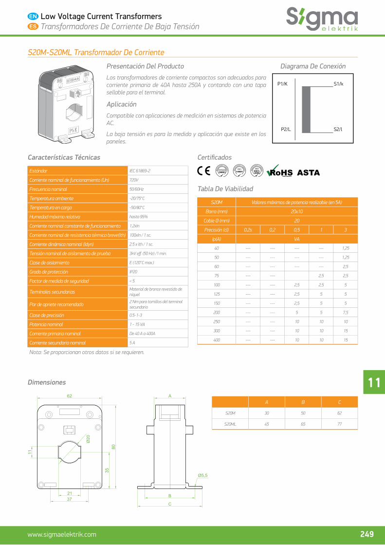
Los transformadores de corriente compactos son adecuados para corriente primaria de 40A hasta 250A y contando con una tapa sellable para el terminal.
Aplicación
Compatible con aplicaciones de medición en sistemas de potencia AC.
La baja tensión es para la medida y aplicación que existe en los paneles.
Diagrama De Conexión
P1/K
P2/L S2/l
S1/k
Características Técnicas
Estándar IEC 61869-2
Corriente nominal de funcionamiento (Un) 720V
Frecuencia nominal 50/60Hz
Temperatura ambiente -20/75°C
Temperatura en carga -50/80°C
Humedad máxima relativa hasta 95%
Corriente nominal constante de funcionamiento 1.2xIn
Corriente nominal de resistencia térmica breve (lth)
100xIn/1 seg
Corriente dinámica nominal (ldyn) 2.5 x Ith / 1 seg
Tensión nominal de aislamiento de prueba 3kV eff . (50 Hz) /1 min.
Clase de aislamiento E (máx 120°C)
Grado de protección IP20
Factor de medida de seguridad < 5
Terminales secundarias Material de bronce revestido de níquel
Par de apriete recomendado 2 Nm para tornillos del terminal secundario
Clase de precisión 0.5-1-3
Potencia nominal 1.25 - 15 VA
Corriente primaria nominal De 40A a 250A
Corriente secundaria nominal 5 A
Nota: Se proporcionan otros datos si se requieren.
Certifi cados
Tabla De Viabilidad
S20 Valores máximos de potencia realizable (en 5A)
Barra (mm) 20x10
Cable Ø (mm) 20
Precisión (cl) 0.2s 0,2 0,5 1 3
Ip(A) VA
40 -- -- -- -- 1,5
50 -- -- -- 1,5 2,5
60 -- -- -- 2,5 3,75
75 -- -- 2,5 3,75 7,5
100 -- -- 5 7,5 10
125 -- -- 5 7,5 10
150 -- -- 10 10 15
200 2,5 2,5 10 10 15
250 3,75 3,75 10 10 15
Dimensiones
A B C
S20 40 60 72
S20L 60 80 92
80
100
8511
21
42
50 C
B
A

11
248 www.sigmaelektrik.com
Low Voltage Current Transformers Transformadores De Corriente De Baja Tensión
S20M-S20ML Series Current Transformer
Product Identifi cation
Compact type current transformers are suitable for primary current from 40A to 400A and they have sealable terminal cover.
Application
Fit for measurement applications in AC power systems.
For measurement and application in low voltage panels.
Application Diagram
P1/K
P2/L S2/l
S1/k
Technical Specifi cations
Standard IEC 61869-2
Rated operating voltage (Un) 720V
Rated frequency 50/60Hz
Ambient temperature -20/75°C
Storage temperature -50/80°C
Maximum relative humidity Up to 95%
Rated thermal continuous current 1.2xIn
Rated short-time thermal current (Ith) 100xIn / 1 sc.
Rated dynamic current (Idyn) 2.5 x Ith / 1 sc.
Rated power frequency withstand voltage 3kV eff . (50 Hz) /1 min.
Thermal class of insulation E (120°C max.)
Degree of protection IP20
Instrument security factor < 5
Secondary terminals Nickel plated brass material
Recommended tightening torque For 2 Nm secondary terminal screws
Accuracy class 0.5-1-3
Burden 1 - 15 VA
Rated primary current From 40 A to 400 A
Rated secondary current 5 A
Note: Additional information is provided upon request.
Approvals
Feasibility Table
S20M Max. burden against class index (at 5A)
Bus Bar (mm) 20x10
Cable Ø (mm) 20
Accuracy (cl) 0.2s 0,2 0,5 1 3
Ip(A) VA
40 --- --- --- --- 1,25
50 --- --- --- --- 1,25
60 --- --- --- --- 2,5
75 --- --- 2,5 2,5
100 --- --- 2,5 2,5 5
125 --- --- 2,5 5 5
150 --- --- 2,5 5 5
200 --- --- 5 5 7,5
250 --- --- 10 10 10
300 --- --- 10 10 15
400 --- --- 10 10 15
Dimensions
A B C
S20M 30 50 62
S20ML 45 65 77
11
Ø20
21
C
B
A
11
249www.sigmaelektrik.com
Low Voltage Current Transformers Transformadores De Corriente De Baja Tensión
S20M-S20ML Transformador De Corriente
Presentación Del Producto
Los transformadores de corriente compactos son adecuados para corriente primaria de 40A hasta 250A y contando con una tapa sellable para el terminal.
Aplicación
Compatible con aplicaciones de medición en sistemas de potencia AC.
La baja tensión es para la medida y aplicación que existe en los paneles.
Diagrama De Conexión
P1/K
P2/L S2/l
S1/k
Características Técnicas
Estándar IEC 61869-2
Corriente nominal de funcionamiento (Un) 720V
Frecuencia nominal 50/60Hz
Temperatura ambiente -20/75°C
Temperatura en carga -50/80°C
Humedad máxima relativa hasta 95%
Corriente nominal constante de funcionamiento 1.2xIn
Corriente nominal de resistencia térmica breve(Ith) 100xIn / 1 sc.
Corriente dinámica nominal (Idyn) 2.5 x Ith / 1 sc.
Tensión nominal de aislamiento de prueba 3kV eff . (50 Hz) /1 min.
Clase de aislamiento E (120°C max.)
Grado de protección IP20
Factor de medida de seguridad < 5
Terminales secundarias Material de bronce revestido de níquel
Par de apriete recomendado 2 Nm para tornillos del terminal secundario
Clase de precisión 0.5-1-3
Potencia nominal 1 - 15 VA
Corriente primaria nominal De 40 A a 400A
Corriente secundaria nominal 5 A
Nota: Se proporcionan otros datos si se requieren.
Certifi cados
Tabla De Viabilidad
S20M Valores máximos de potencia realizable (en 5A)
Barra (mm) 20x10
Cable Ø (mm) 20
Precisión (cl) 0.2s 0,2 0,5 1 3
Ip(A) VA
40 --- --- --- --- 1,25
50 --- --- --- --- 1,25
60 --- --- --- --- 2,5
75 --- --- 2,5 2,5
100 --- --- 2,5 2,5 5
125 --- --- 2,5 5 5
150 --- --- 2,5 5 5
200 --- --- 5 5 7,5
250 --- --- 10 10 10
300 --- --- 10 10 15
400 --- --- 10 10 15
Dimensiones
A B C
S20M 30 50 62
S20ML 45 65 77
11
Ø20
21
C
B
A

11
250 www.sigmaelektrik.com
Low Voltage Current Transformers Transformadores De Corriente De Baja Tensión
S25B Series Bar Type Current Transformer
Product Identifi cation
Compact type current transformers are suitable for primary current from 20A to 150A and they have sealable terminal cover.
Application
Fit for measurement applications in AC power systems.
For measurement and application in low voltage panels.
Application Diagram
P1
S1
L
N
S2
P2 X
Technical Specifi cations
Standard IEC 61869-2
Rated operating voltage (Un) 720V
Rated frequency 50/60Hz
Ambient temperature -20/75°C
Storage temperature -50/80°C
Maximum relative humidity Up to 95%
Rated thermal continuous current 1.2xIn
Rated short-time thermal current (Ith) 60xIn / 1 sc.
Rated dynamic current (Idyn) 2.5 x Ith / 1 sc.
Rated power frequency withstand voltage 3kV eff . (50 Hz) /1 min.
Thermal class of insulation E (120°C max.)
Degree of protection IP20
Instrument security factor < 5
Secondary terminals Nickel plated brass material
Recommended tightening torque For 2 Nm secondary terminal screws
Accuracy class 0.5-1-3
Burden 10 - 15 VA
Rated primary current From 20 A to 150 A
Rated secondary current 5 A
Note: Additional information is provided upon request.
Approvals
Feasibility Table
S25B Max. burden against class index (at 5A)
Bus Bar (mm) -
Cable Ø (mm) -
Accuracy (cl) 0.2s 0,2 0,5 1 3
Ip(A) VA
20 3,75 3,75 10 15 20
25 3,75 3,75 10 15 20
30 3,75 3,75 10 15 20
40 3,75 3,75 10 15 20
50 3,75 3,75 10 15 20
60 3,75 3,75 10 15 20
75 3,75 3,75 10 15 20
100 3,75 3,75 10 15 20
125 3,75 3,75 10 15 20
150 3,75 3,75 10 15 20
Dimensions80
100
8542
39
31,5
3
25
85
58
40
Ø8,5

11
251www.sigmaelektrik.com
Low Voltage Current Transformers Transformadores De Corriente De Baja Tensión
S25B Transformador De Corriente De Tipo Barra
Presentación Del Producto
Los transformadores de corriente compactos son adecuados para corriente primaria de 20A hasta 150A y contando con una tapa sellable para el terminal.
Aplicación
Compatible con aplicaciones de medición en sistemas de potencia AC.
La baja tensión es para la medida y aplicación que existe en los paneles.
Diagrama De Conexión
P1
S1
L
N
S2
P2 X
Características Técnicas
Estándar IEC 61869-2
Corriente nominal de funcionamiento (Un) 720V
Frecuencia nominal 50/60Hz
Temperatura ambiente -20/75°C
Temperatura en carga -50/80°C
Humedad máxima relativa hasta 95%
Corriente nominal constante de funcionamiento 1.2xIn
Corriente nominal de resistencia térmica breve(Ith) 60xIn / 1 sc.
Corriente dinámica nominal (Idyn) 2.5 x Ith / 1 sc.
Tensión nominal de aislamiento de prueba 3kV eff . (50 Hz) /1 min.
Clase de aislamiento E (120°C max.)
Grado de protección IP20
Factor de medida de seguridad < 5
Terminales secundarias Material de bronce revestido de níquel
Par de apriete recomendado 2 Nm para tornillos del terminal secundario
Clase de precisión 0.5-1-3
Potencia nominal 10 - 15 VA
Corriente primaria nominal De 40 A a 400A
Corriente secundaria nominal 5 A
Nota: Se proporcionan otros datos si se requieren.
Certifi cados
Tabla De Viabilidad
S25B Valores máximos de potencia realizable (en 5A)
Barra (mm) -
Cable Ø (mm) -
Precisión (cl) 0.2s 0,2 0,5 1 3
Ip(A) VA
20 3,75 3,75 10 15 20
25 3,75 3,75 10 15 20
30 3,75 3,75 10 15 20
40 3,75 3,75 10 15 20
50 3,75 3,75 10 15 20
60 3,75 3,75 10 15 20
75 3,75 3,75 10 15 20
100 3,75 3,75 10 15 20
125 3,75 3,75 10 15 20
150 3,75 3,75 10 15 20
Dimensiones80
100
8542
39
31,5
3
25
85
58
40
Ø8,5
11
252 www.sigmaelektrik.com
Low Voltage Current Transformers Transformadores De Corriente De Baja Tensión
S30-S30L Series Current Transformer
Product Identifi cation
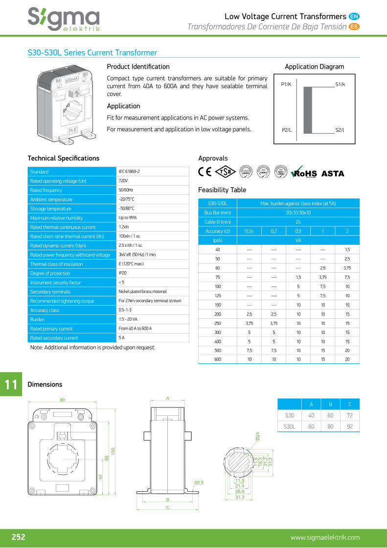
Compact type current transformers are suitable for primary current from 40A to 600A and they have sealable terminal cover.
Application
Fit for measurement applications in AC power systems.
For measurement and application in low voltage panels.
Application Diagram
P1/K
P2/L S2/l
S1/k
Technical Specifi cations
Standard IEC 61869-2
Rated operating voltage (Un) 720V
Rated frequency 50/60Hz
Ambient temperature -20/75°C
Storage temperature -50/80°C
Maximum relative humidity Up to 95%
Rated thermal continuous current 1.2xIn
Rated short-time thermal current (Ith) 100xIn / 1 sc.
Rated dynamic current (Idyn) 2.5 x Ith / 1 sc.
Rated power frequency withstand voltage 3kV eff . (50 Hz) /1 min.
Thermal class of insulation E (120°C max.)
Degree of protection IP20
Instrument security factor < 5
Secondary terminals Nickel plated brass material
Recommended tightening torque For 2 Nm secondary terminal screws
Accuracy class 0.5-1-3
Burden 1.5 - 20 VA
Rated primary current From 40 A to 600 A
Rated secondary current 5 A
Note: Additional information is provided upon request.
Approvals
Feasibility Table
S30-S30L Max. burden against class index (at 5A)
Bus Bar (mm) 20x10/30x10
Cable Ø (mm) 24
Accuracy (cl) 0.2s 0,2 0,5 1 3
Ip(A) VA
40 --- --- --- --- 1,5
50 --- --- --- --- 2,5
60 --- --- --- 2,5 3,75
75 --- --- 1,5 3,75 7,5
100 --- --- 5 7,5 10
125 --- --- 5 7,5 10
150 --- --- 10 10 15
200 2,5 2,5 10 10 15
250 3,75 3,75 10 10 15
300 5 5 10 10 15
400 5 5 10 10 15
500 7,5 7,5 10 15 20
600 10 10 10 15 20
Dimensions
A B C
S30 40 60 72
S30L 60 80 92
80
100
8542
C
B
A
11,521,425,831,3
16,3
21,2
31,3
11,5
Ø24

11
253www.sigmaelektrik.com
Low Voltage Current Transformers Transformadores De Corriente De Baja Tensión
S30-S30L Transformador De Corriente
Presentación Del Producto
Los transformadores de corriente compactos son adecuados para corriente primaria de 40A hasta 600A y contando con una tapa sellable para el terminal.
Aplicación
Compatible con aplicaciones de medición en sistemas de potencia AC.
La baja tensión es para la medida y aplicación que existe en los paneles.
Diagrama De Conexión
P1/K
P2/L S2/l
S1/k
Características Técnicas
Estándar IEC 61869-2
Corriente nominal de funcionamiento (Un) 720V
Frecuencia nominal 50/60Hz
Temperatura ambiente -20/75°C
Temperatura en carga -50/80°C
Humedad máxima relativa hasta 95%
Corriente nominal constante de funcionamiento 1.2xIn
Corriente nominal de resistencia térmica breve(Ith) 100xIn / 1 sc.
Corriente dinámica nominal (Idyn) 2.5 x Ith / 1 sc.
Tensión nominal de aislamiento de prueba 3kV eff . (50 Hz) /1 min.
Clase de aislamiento E (120°C max.)
Grado de protección IP20
Factor de medida de seguridad < 5
Terminales secundarias Material de bronce revestido de níquel
Par de apriete recomendado 2 Nm para tornillos del terminal secundario
Clase de precisión 0.5-1-3
Potencia nominal 1.5 - 20 VA
Corriente primaria nominal De 40 A a 600 A
Corriente secundaria nominal 5 A
Nota: Se proporcionan otros datos si se requieren.
Certifi cados
Tabla De Viabilidad
S30-S30L Valores máximos de potencia realizable (en 5A)
Barra (mm) 20x10/30x10
Cable Ø (mm) 24
Precisión (cl) 0.2s 0,2 0,5 1 3
Ip(A) VA
40 --- --- --- --- 1,5
50 --- --- --- --- 2,5
60 --- --- --- 2,5 3,75
75 --- --- 1,5 3,75 7,5
100 --- --- 5 7,5 10
125 --- --- 5 7,5 10
150 --- --- 10 10 15
200 2,5 2,5 10 10 15
250 3,75 3,75 10 10 15
300 5 5 10 10 15
400 5 5 10 10 15
500 7,5 7,5 10 15 20
600 10 10 10 15 20
Dimensiones
A B C
S30 40 60 72
S30L 60 80 92
80
100
8542
C
B
A
11,521,425,831,3
16,3
21,2
31,3
11,5
Ø24
11
254 www.sigmaelektrik.com
Low Voltage Current Transformers Transformadores De Corriente De Baja Tensión
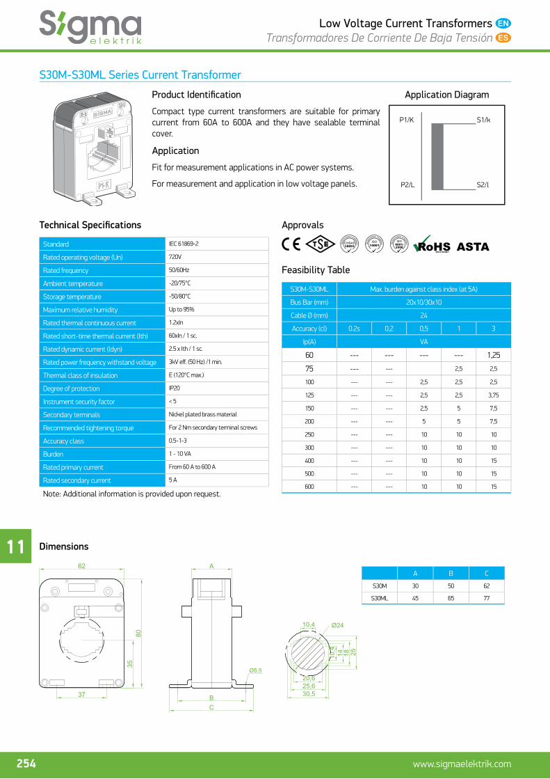
S30M-S30ML Series Current Transformer
Product Identifi cation
Compact type current transformers are suitable for primary current from 60A to 600A and they have sealable terminal cover.
Application
Fit for measurement applications in AC power systems.
For measurement and application in low voltage panels.
Application Diagram
P1/K
P2/L S2/l
S1/k
Technical Specifi cations
Standard IEC 61869-2
Rated operating voltage (Un) 720V
Rated frequency 50/60Hz
Ambient temperature -20/75°C
Storage temperature -50/80°C
Maximum relative humidity Up to 95%
Rated thermal continuous current 1.2xIn
Rated short-time thermal current (Ith) 60xIn / 1 sc.
Rated dynamic current (Idyn) 2.5 x Ith / 1 sc.
Rated power frequency withstand voltage 3kV eff . (50 Hz) /1 min.
Thermal class of insulation E (120°C max.)
Degree of protection IP20
Instrument security factor < 5
Secondary terminals Nickel plated brass material
Recommended tightening torque For 2 Nm secondary terminal screws
Accuracy class 0.5-1-3
Burden 1 - 10 VA
Rated primary current From 60 A to 600 A
Rated secondary current 5 A
Note: Additional information is provided upon request.
Approvals
Feasibility Table
S30M-S30ML Max. burden against class index (at 5A)
Bus Bar (mm) 20x10/30x10
Cable Ø (mm) 24
Accuracy (cl) 0.2s 0,2 0,5 1 3
Ip(A) VA
60 --- --- --- --- 1,25
75 --- --- 2,5 2,5
100 --- --- 2,5 2,5 2,5
125 --- --- 2,5 2,5 3,75
150 --- --- 2,5 5 7,5
200 --- --- 5 5 7,5
250 --- --- 10 10 10
300 --- --- 10 10 10
400 --- --- 10 10 15
500 --- --- 10 10 15
600 --- --- 10 10 15
Dimensions
A B C
S30M 30 50 62
S30ML 45 65 77
A
BC
2510,414 18
20,625,630,5
10,4 Ø24
11
255www.sigmaelektrik.com
Low Voltage Current Transformers Transformadores De Corriente De Baja Tensión
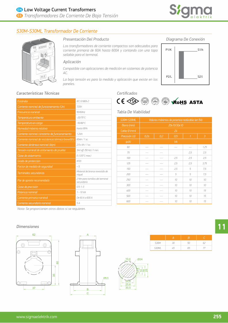
S30M-S30ML Transformador De Corriente
Presentación Del Producto
Los transformadores de corriente compactos son adecuados para corriente primaria de 60A hasta 600A y contando con una tapa sellable para el terminal.
Aplicación
Compatible con aplicaciones de medición en sistemas de potencia AC.
La baja tensión es para la medida y aplicación que existe en los paneles.
Diagrama De Conexión
P1/K
P2/L S2/l
S1/k
Características Técnicas
Estándar IEC 61869-2
Corriente nominal de funcionamiento (Un) 720V
Frecuencia nominal 50/60Hz
Temperatura ambiente -20/75°C
Temperatura en carga -50/80°C
Humedad máxima relativa hasta 95%
Corriente nominal constante de funcionamiento 1.2xIn
Corriente nominal de resistencia térmica breve(Ith) 60xIn / 1 sc.
Corriente dinámica nominal (Idyn) 2.5 x Ith / 1 sc.
Tensión nominal de aislamiento de prueba 3kV eff . (50 Hz) /1 min.
Clase de aislamiento E (120°C max.)
Grado de protección IP20
Factor de medida de seguridad < 5
Terminales secundarias Material de bronce revestido de níquel
Par de apriete recomendado 2 Nm para tornillos del terminal secundario
Clase de precisión 0.5-1-3
Potencia nominal 1 - 10 VA
Corriente primaria nominal De 60 A a 600 A
Corriente secundaria nominal 5 A
Nota: Se proporcionan otros datos si se requieren.
Certifi cados
Tabla De Viabilidad
S30M-S30ML Valores máximos de potencia realizable (en 5A)
Barra (mm) 20x10/30x10
Cable Ø (mm) 24
Precisión (cl) 0.2s 0,2 0,5 1 3
Ip(A) VA
60 --- --- --- --- 1,25
75 --- --- 2,5 2,5
100 --- --- 2,5 2,5 2,5
125 --- --- 2,5 2,5 3,75
150 --- --- 2,5 5 7,5
200 --- --- 5 5 7,5
250 --- --- 10 10 10
300 --- --- 10 10 10
400 --- --- 10 10 15
500 --- --- 10 10 15
600 --- --- 10 10 15
Dimensiones
A B C
S30M 30 50 62
S30ML 45 65 77
A
BC
2510,414 18
20,625,630,5
10,4 Ø24

11
256 www.sigmaelektrik.com
Low Voltage Current Transformers Transformadores De Corriente De Baja Tensión
S40 Series Current Transformer
Product Identifi cation
Compact type current transformers are suitable for primary current from 150A to 600A and they have sealable terminal cover.
Application
Fit for measurement applications in AC power systems.
For measurement and application in low voltage panels.
Application Diagram
P1/K
P2/L S2/l
S1/k
Technical Specifi cations
Standard IEC 61869-2
Rated operating voltage (Un) 720V
Rated frequency 50/60Hz
Ambient temperature -20/75°C
Storage temperature -50/80°C
Maximum relative humidity Up to 95%
Rated thermal continuous current 1.2xIn
Rated short-time thermal current (Ith) 100xIn / 1 sc.
Rated dynamic current (Idyn) 2.5 x Ith / 1 sc.
Rated power frequency withstand voltage 3kV eff . (50 Hz) /1 min.
Thermal class of insulation E (120°C max.)
Degree of protection IP20
Instrument security factor < 5
Secondary terminals Nickel plated brass material
Recommended tightening torque For 2 Nm secondary terminal screws
Accuracy class 0.5-1-3
Burden 2.5 - 15 VA
Rated primary current From 150 A to 600 A
Rated secondary current 5 A
Note: Additional information is provided upon request.
Approvals
Feasibility Table
S40 Max. burden against class index (at 5A)
Bus Bar (mm) 40x10
Cable Ø (mm) 31
Accuracy (cl) 0.2s 0,2 0,5 1 3
Ip(A) VA
150 -- -- 2,5 3,75 5
200 -- -- 3,75 5 7,5
250 -- -- 7,5 10 15
300 2,5 2,5 10 10 15
400 3,75 3,75 10 15 20
500 5 5 10 15 30
600 7,5 7,5 10 15 30
Dimensions
A B C
S40 40 60 72
S40L 60 80 92
80
100
8542
CB
A
Ø31
41,210,7
10,7
41,2
50

11
257www.sigmaelektrik.com
Low Voltage Current Transformers Transformadores De Corriente De Baja Tensión
S40 Transformador De Corriente
Presentación Del Producto
Los transformadores de corriente compactos son adecuados para corriente primaria de 150A hasta 600A y contando con una tapa sellable para el terminal.
Aplicación
Compatible con aplicaciones de medición en sistemas de potencia AC.
La baja tensión es para la medida y aplicación que existe en los paneles.
Diagrama De Conexión
P1/K
P2/L S2/l
S1/k
Características Técnicas
Estándar IEC 61869-2
Corriente nominal de funcionamiento (Un) 720V
Frecuencia nominal 50/60Hz
Temperatura ambiente -20/75°C
Temperatura en carga -50/80°C
Humedad máxima relativa hasta 95%
Corriente nominal constante de funcionamiento 1.2xIn
Corriente nominal de resistencia térmica breve(Ith) 100xIn / 1 sc.
Corriente dinámica nominal (Idyn) 2.5 x Ith / 1 sc.
Tensión nominal de aislamiento de prueba 3kV eff . (50 Hz) /1 min.
Clase de aislamiento E (120°C max.)
Grado de protección IP20
Factor de medida de seguridad < 5
Terminales secundarias Material de bronce revestido de níquel
Par de apriete recomendado 2 Nm para tornillos del terminal secundario
Clase de precisión 0.5-1-3
Potencia nominal 2.5 - 15 VA
Corriente primaria nominal De 150 A a 600 A
Corriente secundaria nominal 5 A
Nota: Se proporcionan otros datos si se requieren.
Certifi cados
Tabla De Viabilidad
S40 Valores máximos de potencia realizable (en 5A)
Barra (mm) 40x10
Cable Ø (mm) 31
Precisión (cl) 0.2s 0,2 0,5 1 3
Ip(A) VA
150 -- -- 2,5 3,75 5
200 -- -- 3,75 5 7,5
250 -- -- 7,5 10 15
300 2,5 2,5 10 10 15
400 3,75 3,75 10 15 20
500 5 5 10 15 30
600 7,5 7,5 10 15 30
Dimensiones
A B C
S40 40 60 72
S40L 60 80 92
80
100
8542
CB
A
Ø31
41,210,7
10,7
41,2
50
11
258 www.sigmaelektrik.com
Low Voltage Current Transformers Transformadores De Corriente De Baja Tensión
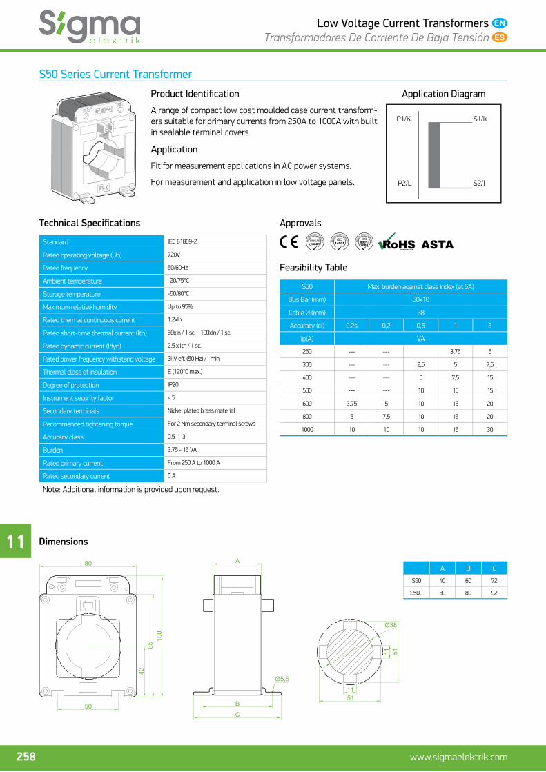
S50 Series Current Transformer
Product Identifi cation
A range of compact low cost moulded case current transform-ers suitable for primary currents from 250A to 1000A with built in sealable terminal covers.
Application
Fit for measurement applications in AC power systems.
For measurement and application in low voltage panels.
Application Diagram
P1/K
P2/L S2/l
S1/k
Technical Specifi cations
Standard IEC 61869-2
Rated operating voltage (Un) 720V
Rated frequency 50/60Hz
Ambient temperature -20/75°C
Storage temperature -50/80°C
Maximum relative humidity Up to 95%
Rated thermal continuous current 1.2xIn
Rated short-time thermal current (Ith) 60xIn / 1 sc. - 100xIn / 1 sc.
Rated dynamic current (Idyn) 2.5 x Ith / 1 sc.
Rated power frequency withstand voltage 3kV eff . (50 Hz) /1 min.
Thermal class of insulation E (120°C max.)
Degree of protection IP20
Instrument security factor < 5
Secondary terminals Nickel plated brass material
Recommended tightening torque For 2 Nm secondary terminal screws
Accuracy class 0.5-1-3
Burden 3.75 - 15 VA
Rated primary current From 250 A to 1000 A
Rated secondary current 5 A
Note: Additional information is provided upon request.
Approvals
Feasibility Table
S50 Max. burden against class index (at 5A)
Bus Bar (mm) 50x10
Cable Ø (mm) 38
Accuracy (cl) 0.2s 0,2 0,5 1 3
Ip(A) VA
250 --- --- 3,75 5
300 --- --- 2,5 5 7,5
400 --- --- 5 7,5 15
500 --- --- 10 10 15
600 3,75 5 10 15 20
800 5 7,5 10 15 20
1000 10 10 10 15 30
Dimensions
A B C
S50 40 60 72
S50L 60 80 92
80
100
8542
C
B
A
1151
Ø38
Ø5,5
11 51
50

11
259www.sigmaelektrik.com
Low Voltage Current Transformers Transformadores De Corriente De Baja Tensión
S50 Transformador De Corriente
Presentación Del Producto
Los transformadores de corriente compactos son adecuados para corriente primaria de 250A hasta 1000A y contando con una tapa sellable para el terminal.
Aplicación
Compatible con aplicaciones de medición en sistemas de potencia AC.
La baja tensión es para la medida y aplicación que existe en los paneles.
Diagrama De Conexión
P1/K
P2/L S2/l
S1/k
Características Técnicas
Estándar IEC 61869-2
Corriente nominal de funcionamiento (Un) 720V
Frecuencia nominal 50/60Hz
Temperatura ambiente -20/75°C
Temperatura en carga -50/80°C
Humedad máxima relativa Hasta 95%
Corriente nominal constante de funcionamiento 1.2xIn
Corriente nominal de resistencia térmica breve(Ith) 60xIn / 1 sc. - 100xIn / 1 sc.
Corriente dinámica nominal (Idyn) 2.5 x Ith / 1 sc.
Tensión nominal de aislamiento de prueba 3kV eff . (50 Hz) /1 min.
Clase de aislamiento E (120°C max.)
Grado de protección IP20
Factor de medida de seguridad < 5
Terminales secundarias Material de bronce revestido de níquel
Par de apriete recomendado 2 Nm para tornillos del terminal secundario
Clase de precisión 0.5-1-3
Potencia nominal 3.75 - 15 VA
Corriente primaria nominal De 250 A a 1000 A
Corriente secundaria nominal 5 A
Nota: Se proporcionan otros datos si se requieren.
Certifi cados
Tabla De Viabilidad
S50 Valores máximos de potencia realizable (en 5A)
Barra (mm) 50x10
Cable Ø (mm) 38
Precisión (cl) 0.2s 0,2 0,5 1 3
Ip(A) VA
250 --- --- 3,75 5
300 --- --- 2,5 5 7,5
400 --- --- 5 7,5 15
500 --- --- 10 10 15
600 3,75 5 10 15 20
800 5 7,5 10 15 20
1000 10 10 10 15 30
Dimensiones
A B C
S50 40 60 72
S50L 60 80 92
80
100
8542
C
B
A
1151
Ø38
Ø5,5
11 51
50

11
260 www.sigmaelektrik.com
Low Voltage Current Transformers Transformadores De Corriente De Baja Tensión
S60 Series Current Transformer
Product Identifi cation
Compact type current transformers are suitable for primary current from 300 A to 1600 A and they have sealable terminal cover.
Application
Fit for measurement applications in AC power systems.
For measurement and application in low voltage panels.
Application Diagram
P1/K
P2/L S2/l
S1/k
Technical Specifi cations
Standard IEC 61869-2
Rated operating voltage (Un) 720V
Rated frequency 50/60Hz
Ambient temperature -20/75°C
Storage temperature -50/80°C
Maximum relative humidity Up to 95%
Rated thermal continuous current 1.2xIn
Rated short-time thermal current (Ith) 60xIn / 1 sc.
Rated dynamic current (Idyn) 2.5 x Ith / 1 sc.
Rated power frequency withstand voltage 3kV eff . (50 Hz) /1 min.
Thermal class of insulation E (120°C max.)
Degree of protection IP20
Instrument security factor < 5
Secondary terminals Nickel plated brass material
Recommended tightening torque For 2 Nm secondary terminal screws
Accuracy class 0.5-1-3
Burden 5 - 30 VA
Rated primary current From 300A to 1600A
Rated secondary current 5 A
Note: Additional information is provided upon request.
Approvals
Feasibility Table
S60 Max. burden against class index (at 5A)
Bus Bar (mm) 60x10
Cable Ø (mm) 46
Accuracy (cl) 0.2s 0,2 0,5 1 3
Ip(A) VA
300 -- -- 3,75 5 12,5
400 -- -- 5 7,5 15
500 -- -- 7,5 10 15
600 3,75 3,75 10 15 20
800 5 5 15 15 20
1000 7,5 7,5 15 15 30
1200 7,5 7,5 15 15 30
1250 7,5 7,5 15 15 30
1500 10 10 15 15 30
1600 15 15 15 15 30
Dimensions
132
107
11,252,561,2
Ø46
21,231 61.2
58117
45
65
Ø5,5
7748

11
261www.sigmaelektrik.com
Low Voltage Current Transformers Transformadores De Corriente De Baja Tensión
S60 Transformador De Corriente
Presentación Del Producto
Los transformadores de corriente compactos son adecuados para corriente primaria de 300A hasta 1600A contando con una tapa sellable para el terminal.
Aplicación
Compatible con aplicaciones de medición en sistemas de potencia AC.
La baja tensión es para la medida y aplicación que existe en los paneles.
Diagrama De Conexión
P1/K
P2/L S2/l
S1/k
Características Técnicas
Estándar IEC 61869-2
Corriente nominal de funcionamiento (Un) 720V
Frecuencia nominal 50/60Hz
Temperatura ambiente -20/75°C
Temperatura en carga -50/80°C
Humedad máxima relativa hasta 95%
Corriente nominal constante de funcionamiento 1.2xIn
Corriente nominal de resistencia térmica breve(Ith) 60xIn / 1 sc.
Corriente dinámica nominal (Idyn) 2.5 x Ith / 1 sc.
Tensión nominal de aislamiento de prueba 3kV eff . (50 Hz) /1 min.
Clase de aislamiento E (120°C max.)
Grado de protección IP20
Factor de medida de seguridad < 5
Terminales secundarias Material de bronce revestido de níquel
Par de apriete recomendado 2 Nm para tornillos del terminal secundario
Clase de precisión 0.5-1-3
Potencia nominal 5 - 30 VA
Corriente primaria nominal De 300A a 1600A
Corriente secundaria nominal 5 A
Nota: Se proporcionan otros datos si se requieren.
Certifi cados
Tabla De Viabilidad
S60 Valores máximos de potencia realizable (en 5A)
Barra (mm) 60x10
Cable Ø (mm) 46
Precisión (cl) 0.2s 0,2 0,5 1 3
Ip(A) VA
300 -- -- 3,75 5 12,5
400 -- -- 5 7,5 15
500 -- -- 7,5 10 15
600 3,75 3,75 10 15 20
800 5 5 15 15 20
1000 7,5 7,5 15 15 30
1200 7,5 7,5 15 15 30
1250 7,5 7,5 15 15 30
1500 10 10 15 15 30
1600 15 15 15 15 30
Dimensiones
132
107
11,252,561,2
Ø46
21,231 61.2
58117
45
65
Ø5,5
7748

11
262 www.sigmaelektrik.com
Low Voltage Current Transformers Transformadores De Corriente De Baja Tensión
S60A Series Current Transformer (Split Core Current Transformer)
Product Identifi cation
Compact type current transformers are suitable for primary current from 400 A to 1000A and they have sealable terminal cover.
Application
Fit for measurement applications in AC power systems.
For measurement and application in low voltage panels.
Application Diagram
P1/K
P2/L S2/l
S1/k
Technical Specifi cations
Standard IEC 61869-2
Rated operating voltage (Un) 720V
Rated frequency 50/60Hz
Ambient temperature -20/75°C
Storage temperature -50/80°C
Maximum relative humidity Up to 95%
Rated thermal continuous current 1.2xIn
Rated short-time thermal current (Ith) 60xIn / 1 sc.
Rated dynamic current (Idyn) 2.5 x Ith / 1 sc.
Rated power frequency withstand voltage 3kV eff . (50 Hz) /1 min.
Thermal class of insulation E (120°C max.)
Degree of protection IP20
Instrument security factor < 5
Secondary terminals Nickel plated brass material
Recommended tightening torque For 2 Nm secondary terminal screws
Accuracy class 0.5-1-3
Burden 3.75 - 15 VA
Rated primary current From 400 A to 1000 A
Rated secondary current 5 A
Note: Additional information is provided upon request.
Approvals
Feasibility Table
S60A Max. burden against class index (at 5A)
Bus Bar (mm) 60x10
Cable Ø (mm) 31
Accuracy (cl) 0.2s 0,2 0,5 1 3
Ip(A) VA
400 --- --- --- 3,75 5
500 --- --- --- 5 7,5
600 --- --- 5 7,5 10
800 --- --- 7,5 10 12,5
1000 --- --- 10 15 15
Dimensions
67130 145
40
6072
85
10231
61
11
263www.sigmaelektrik.com
Low Voltage Current Transformers Transformadores De Corriente De Baja Tensión
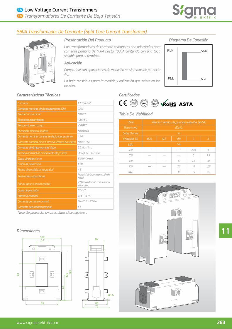
S60A Transformador De Corriente (Split Core Current Transformer)
Presentación Del Producto
Los transformadores de corriente compactos son adecuados para corriente primaria de 400A hasta 1000A contando con una tapa sellable para el terminal.
Aplicación
Compatible con aplicaciones de medición en sistemas de potencia AC.
La baja tensión es para la medida y aplicación que existe en los paneles.
Diagrama De Conexión
P1/K
P2/L S2/l
S1/k
Características Técnicas
Estándar IEC 61869-2
Corriente nominal de funcionamiento (Un) 720V
Frecuencia nominal 50/60Hz
Temperatura ambiente -20/75°C
Temperatura en carga -50/80°C
Humedad máxima relativa hasta 95%
Corriente nominal constante de funcionamiento 1.2xIn
Corriente nominal de resistencia térmica breve(Ith) 60xIn / 1 sc.
Corriente dinámica nominal (Idyn) 2.5 x Ith / 1 sc.
Tensión nominal de aislamiento de prueba 3kV eff . (50 Hz) /1 min.
Clase de aislamiento E (120°C max.)
Grado de protección IP20
Factor de medida de seguridad < 5
Terminales secundarias Material de bronce revestido de níquel
Par de apriete recomendado 2 Nm para tornillos del terminal secundario
Clase de precisión 0.5-1-3
Potencia nominal 3.75 - 15 VA
Corriente primaria nominal De 400 A a 1000 A
Corriente secundaria nominal 5 A
Nota: Se proporcionan otros datos si se requieren.
Certifi cados
Tabla De Viabilidad
S60A Valores máximos de potencia realizable (en 5A)
Barra (mm) 60x10
Cable Ø (mm) 31
Precisión (cl) 0.2s 0,2 0,5 1 3
Ip(A) VA
400 --- --- --- 3,75 5
500 --- --- --- 5 7,5
600 --- --- 5 7,5 10
800 --- --- 7,5 10 12,5
1000 --- --- 10 15 15
Dimensiones
67130 145
40
6072
85
10231
61

11
264 www.sigmaelektrik.com
Low Voltage Current Transformers Transformadores De Corriente De Baja Tensión
S60D Series Current Transformer
Product Identifi cation
Compact type current transformers are suitable for primary current from 600 A to 1600A and they have sealable terminal cover.
Application
Fit for measurement applications in AC power systems.
For measurement and application in low voltage panels.
Application Diagram
P1/K
P2/L S2/l
S1/k
Technical Specifi cations
Standard IEC 61869-2
Rated operating voltage (Un) 720V
Rated frequency 50/60Hz
Ambient temperature -20/75°C
Storage temperature -50/80°C
Maximum relative humidity Up to 95%
Rated thermal continuous current 1.2xIn
Rated short-time thermal current (Ith) 60xIn / 1 sc.
Rated dynamic current (Idyn) 2.5 x Ith / 1 sc.
Rated power frequency withstand voltage 3kV eff . (50 Hz) /1 min.
Thermal class of insulation E (120°C max.)
Degree of protection IP20
Instrument security factor < 5
Secondary terminals Nickel plated brass material
Recommended tightening torque For 2 Nm secondary terminal screws
Accuracy class 0.5-1-3
Burden 5 - 30 VA
Rated primary current From 600A to 1600A
Rated secondary current 5 A
Note: Additional information is provided upon request.
Approvals
Feasibility Table
S60D Max. burden against class index (at 5A)
Bus Bar (mm) 60x10
Cable Ø (mm) 31
Accuracy (cl) 0.2s 0,2 0,5 1 3
Ip(A) VA
600 --- --- 5 7,5 10
750 --- --- 7,5 10 15
1000 --- --- 10 15 15
1200 --- --- 15 15 15
1250 --- --- 15 15 15
1500 --- --- 15 15 30
1600 --- --- 15 15 30
Dimensions
31 134
119
62
82
489280
Ø5,5
6061

11
265www.sigmaelektrik.com
Low Voltage Current Transformers Transformadores De Corriente De Baja Tensión
S60D Transformador De Corriente
Presentación Del Producto
Los transformadores de corriente compactos son adecuados para corriente primaria de 600A hasta 1600A contando con una tapa sellable para el terminal.
Aplicación
Compatible con aplicaciones de medición en sistemas de potencia AC.
La baja tensión es para la medida y aplicación que existe en los paneles.
Diagrama De Conexión
P1/K
P2/L S2/l
S1/k
Características Técnicas
Estándar IEC 61869-2
Corriente nominal de funcionamiento (Un) 720V
Frecuencia nominal 50/60Hz
Temperatura ambiente -20/75°C
Temperatura en carga -50/80°C
Humedad máxima relativa hasta 95%
Corriente nominal constante de funcionamiento 1.2xIn
Corriente nominal de resistencia térmica breve(Ith) 60xIn / 1 sc.
Corriente dinámica nominal (Idyn) 2.5 x Ith / 1 sc.
Tensión nominal de aislamiento de prueba 3kV eff . (50 Hz) /1 min.
Clase de aislamiento E (120°C max.)
Grado de protección IP20
Factor de medida de seguridad < 5
Terminales secundarias Material de bronce revestido de níquel
Par de apriete recomendado 2 Nm para tornillos del terminal secundario
Clase de precisión 0.5-1-3
Potencia nominal 5 - 30 VA
Corriente primaria nominal De 600A a 1600A
Corriente secundaria nominal 5 A
Nota: Se proporcionan otros datos si se requieren.
Certifi cados
Tabla De Viabilidad
S60D Valores máximos de potencia realizable (en 5A)
Barra (mm) 60x10
Cable Ø (mm) 31
Precisión (cl) 0.2s 0,2 0,5 1 3
Ip(A) VA
600 --- --- 5 7,5 10
750 --- --- 7,5 10 15
1000 --- --- 10 15 15
1200 --- --- 15 15 15
1250 --- --- 15 15 15
1500 --- --- 15 15 30
1600 --- --- 15 15 30
Dimensiones
31 134
119
62
82
489280
Ø5,5
6061

11
266 www.sigmaelektrik.com
Low Voltage Current Transformers Transformadores De Corriente De Baja Tensión
S80 Series Current Transformer
Product Identifi cation
Compact type current transformers are suitable for primary current from 750 A to 2000A and they have sealable terminal cover.
Application
Fit for measurement applications in AC power systems.
For measurement and application in low voltage panels.
Application Diagram
P1/K
P2/L S2/l
S1/k
Technical Specifi cations
Standard IEC 61869-2
Rated operating voltage (Un) 720V
Rated frequency 50/60Hz
Ambient temperature -20/75°C
Storage temperature -50/80°C
Maximum relative humidity Up to 95%
Rated thermal continuous current 1.2xIn
Rated short-time thermal current (Ith) 100kA 1 sc.
Rated dynamic current (Idyn) 2.5 x Ith / 1 sc.
Rated power frequency withstand voltage 3kV eff . (50 Hz) /1 min.
Thermal class of insulation E (120°C max.)
Degree of protection IP20
Instrument security factor < 5
Secondary terminals Nickel plated brass material
Recommended tightening torque For 2 Nm secondary terminal screws
Accuracy class 0.5-1-3
Burden 7.5 - 30 VA
Rated primary current From 750 A to 2000 A
Rated secondary current 5 A
Note: Additional information is provided upon request.
Approvals
Feasibility Table
S80 Max. burden against class index (at 5A)
Bus Bar (mm) 2 (80x10)
Cable Ø (mm) 31
Accuracy (cl) 0.2s 0,2 0,5 1 3
Ip(A) VA
750 2,5 2,5 10 15 20
800 3,75 3,75 10 15 20
1000 5 5 15 20 30
1200 5 5 15 20 30
1250 5 5 15 20 30
1500 7,5 7,5 15 20 30
1600 10 10 15 20 30
2000 15 15 15 20 30
Dimensions
73150 165
145
75
Ø5,5
87
82
32
55
80

11
267www.sigmaelektrik.com
Low Voltage Current Transformers Transformadores De Corriente De Baja Tensión
S80 Transformador De Corriente
Presentación Del Producto
Los transformadores de corriente compactos son adecuados para corriente primaria de 750A hasta 2000A contando con una tapa sellable para el terminal.
Aplicación
Compatible con aplicaciones de medición en sistemas de potencia AC.
La baja tensión es para la medida y aplicación que existe en los paneles.
Diagrama De Conexión
P1/K
P2/L S2/l
S1/k
Características Técnicas
Estándar IEC 61869-2
Corriente nominal de funcionamiento (Un) 720V
Frecuencia nominal 50/60Hz
Temperatura ambiente -20/75°C
Temperatura en carga -50/80°C
Humedad máxima relativa hasta 95%
Corriente nominal constante de funcionamiento 1.2xIn
Corriente nominal de resistencia térmica breve(Ith) 100kA 1 sc.
Corriente dinámica nominal (Idyn) 2.5 x Ith / 1 sc.
Tensión nominal de aislamiento de prueba 3kV eff . (50 Hz) /1 min.
Clase de aislamiento E (120°C max.)
Grado de protección IP20
Factor de medida de seguridad < 5
Terminales secundarias Material de bronce revestido de níquel
Par de apriete recomendado 2 Nm para tornillos del terminal secundario
Clase de precisión 0.5-1-3
Potencia nominal 7.5 - 30 VA
Corriente primaria nominal De 750 A a 2000 A
Corriente secundaria nominal 5 A
Nota: Se proporcionan otros datos si se requieren.
Certifi cados
Tabla De Viabilidad
S80 Valores máximos de potencia realizable (en 5A)
Barra (mm) 2 (80x10)
Cable Ø (mm) 31
Precisión (cl) 0.2s 0,2 0,5 1 3
Ip(A) VA
750 2,5 2,5 10 15 20
800 3,75 3,75 10 15 20
1000 5 5 15 20 30
1200 5 5 15 20 30
1250 5 5 15 20 30
1500 7,5 7,5 15 20 30
1600 10 10 15 20 30
2000 15 15 15 20 30
Dimensiones
73150 165
145
75
Ø5,5
87
82
32
55
80

11
268 www.sigmaelektrik.com
Low Voltage Current Transformers Transformadores De Corriente De Baja Tensión
S100 Series Current Transformer
Product Identifi cation
Compact type current transformers are applicable for primary current from 750A to 3000A and sealable terminal cover is available.
Application
Fit for measurement applications in AC power systems.
For measurement and application in low voltage panels.
Application Diagram
P1/K
P2/L S2/l
S1/k
Technical Specifi cations
Standard IEC 61869-2
Rated operating voltage (Un) 720V
Rated frequency 50/60Hz
Ambient temperature -20/75°C
Storage temperature -50/80°C
Maximum relative humidity Up to 95%
Rated thermal continuous current 1.2xIn
Rated short-time thermal current (Ith) 100kA 1 sc.
Rated dynamic current (Idyn) 2.5 x Ith / 1 sc.
Rated power frequency withstand voltage 3kV eff . (50 Hz) /1 min.
Thermal class of insulation E (120°C max.)
Degree of protection IP20
Instrument security factor < 5
Secondary terminals Nickel plated brass material
Recommended tightening torque For 2 Nm secondary terminal screws
Accuracy class 0.5-1-3
Burden 15 - 30 VA
Rated primary current From 750 A to 3000 A
Rated secondary current 5 A
Note: Additional information is provided upon request.
Approvals
Feasibility Table
S100 Max. burden against class index (at 5A)
Bus Bar (mm) 100x10
Cable Ø (mm) 62
Accuracy (cl) 0.2s 0,2 0,5 1 3
Ip(A) VA
750 2,5 2,5 10 15 15
800 3,75 3,75 15 20 20
1000 5 5 15 20 30
1200 5 5 15 20 30
1250 5 5 15 20 30
1500 7,5 7,5 15 20 30
1600 10 10 15 20 30
2000 15 15 15 20 30
2500 15 15 15 20 30
3000 15 15 30 30 45
Dimensions
73150 165
145
7587
55
80 6181101
11
Ø62
32
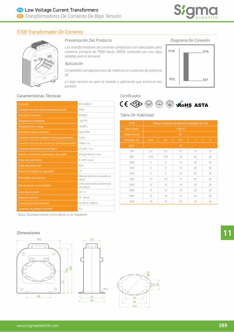
11
269www.sigmaelektrik.com
Low Voltage Current Transformers Transformadores De Corriente De Baja Tensión
S100 Transformador De Corriente
Presentación Del Producto
Los transformadores de corriente compactos son adecuados para corriente primaria de 750A hasta 3000A contando con una tapa sellable para el terminal.
Aplicación
Compatible con aplicaciones de medición en sistemas de potencia AC.
La baja tensión es para la medida y aplicación que existe en los paneles.
Diagrama De Conexión
P1/K
P2/L S2/l
S1/k
Características Técnicas
Estándar IEC 61869-2
Corriente nominal de funcionamiento (Un) 720V
Frecuencia nominal 50/60Hz
Temperatura ambiente -20/75°C
Temperatura en carga -50/80°C
Humedad máxima relativa hasta 95%
Corriente nominal constante de funcionamiento 1.2xIn
Corriente nominal de resistencia térmica breve(Ith) 100kA 1 sc.
Corriente dinámica nominal (Idyn) 2.5 x Ith / 1 sc.
Tensión nominal de aislamiento de prueba 3kV eff . (50 Hz) /1 min.
Clase de aislamiento E (120°C max.)
Grado de protección IP20
Factor de medida de seguridad < 5
Terminales secundarias Material de bronce revestido de níquel
Par de apriete recomendado 2 Nm para tornillos del terminal secundario
Clase de precisión 0.5-1-3
Potencia nominal 15 - 30 VA
Corriente primaria nominal De 750 A a 3000 A
Corriente secundaria nominal 5 A
Nota: Se proporcionan otros datos si se requieren.
Certifi cados
Tabla De Viabilidad
S100 Valores máximos de potencia realizable (en 5A)
Barra (mm) 100x10
Cable Ø (mm) 62
Precisión (cl) 0.2s 0,2 0,5 1 3
Ip(A) VA
750 2,5 2,5 10 15 15
800 3,75 3,75 15 20 20
1000 5 5 15 20 30
1200 5 5 15 20 30
1250 5 5 15 20 30
1500 7,5 7,5 15 20 30
1600 10 10 15 20 30
2000 15 15 15 20 30
2500 15 15 15 20 30
3000 15 15 30 30 45
Dimensiones
73150 165
145
7587
55
80 6181101
11
Ø62
32

11
270 www.sigmaelektrik.com
Low Voltage Current Transformers Transformadores De Corriente De Baja Tensión
S100D Series Current Transformer
Product Identifi cation
Compact type current transformers are suitable for primary current from 600 A to 4000A and they have sealable terminal cover.
Application
Fit for measurement applications in AC power systems.
For measurement and application in low voltage panels.
Application Diagram
P1/K
P2/L S2/l
S1/k
Technical Specifi cations
Standard IEC 61869-2
Rated operating voltage (Un) 720V
Rated frequency 50/60Hz
Ambient temperature -20/75°C
Storage temperature -50/80°C
Maximum relative humidity Up to 95%
Rated thermal continuous current 1.2xIn
Rated short-time thermal current (Ith) 100kA 1 sc.
Rated dynamic current (Idyn) 2.5 x Ith / 1 sc.
Rated power frequency withstand voltage 3kV eff . (50 Hz) /1 min.
Thermal class of insulation E (120°C max.)
Degree of protection IP20
Instrument security factor < 5
Secondary terminals Nickel plated brass material
Recommended tightening torque For 2 Nm secondary terminal screws
Accuracy class 0.5-1-3
Burden 10 - 30 VA
Rated primary current From 600 A to 4000 A
Rated secondary current 5 A
Note: Additional information is provided upon request.
Approvals
Feasibility Table
S100D Max. burden against class index (at 5A)
Bus Bar (mm) 4 (100x10)
Cable Ø (mm) 70
Accuracy (cl) 0.2s 0,2 0,5 1 3
Ip(A) VA
600 --- --- 5 7,5 10
800 --- --- 7,5 10 20
1000 --- --- 10 15 20
1200 --- --- 15 15 30
1250 --- --- 15 15 30
1500 --- --- 15 20 30
1600 --- --- 15 20 30
2000 --- --- 15 20 30
2500 --- --- 15 20 30
3000 --- --- 15 20 30
4000 --- --- 15 20 30
Dimensions
109128
128
75
Ø5,5
87
55
87178 193
47102
101
73
92
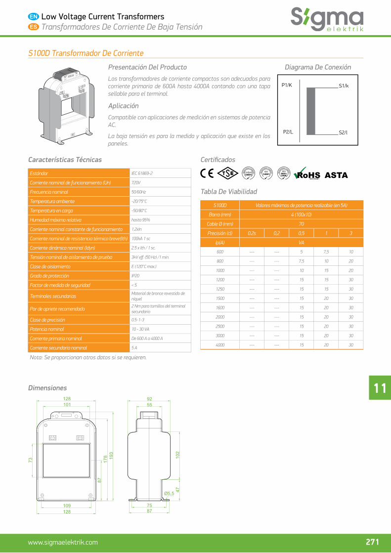
11
271www.sigmaelektrik.com
Low Voltage Current Transformers Transformadores De Corriente De Baja Tensión
S100D Transformador De Corriente
Presentación Del Producto
Los transformadores de corriente compactos son adecuados para corriente primaria de 600A hasta 4000A contando con una tapa sellable para el terminal.
Aplicación
Compatible con aplicaciones de medición en sistemas de potencia AC.
La baja tensión es para la medida y aplicación que existe en los paneles.
Diagrama De Conexión
P1/K
P2/L S2/l
S1/k
Características Técnicas
Estándar IEC 61869-2
Corriente nominal de funcionamiento (Un) 720V
Frecuencia nominal 50/60Hz
Temperatura ambiente -20/75°C
Temperatura en carga -50/80°C
Humedad máxima relativa hasta 95%
Corriente nominal constante de funcionamiento 1.2xIn
Corriente nominal de resistencia térmica breve(Ith) 100kA 1 sc
Corriente dinámica nominal (Idyn) 2.5 x Ith / 1 sc.
Tensión nominal de aislamiento de prueba 3kV eff . (50 Hz) /1 min.
Clase de aislamiento E (120°C max.)
Grado de protección IP20
Factor de medida de seguridad < 5
Terminales secundarias Material de bronce revestido de níquel
Par de apriete recomendado 2 Nm para tornillos del terminal secundario
Clase de precisión 0.5-1-3
Potencia nominal 10 - 30 VA
Corriente primaria nominal De 600 A a 4000 A
Corriente secundaria nominal 5 A
Nota: Se proporcionan otros datos si se requieren.
Certifi cados
Tabla De Viabilidad
S100D Valores máximos de potencia realizable (en 5A)
Barra (mm) 4 (100x10)
Cable Ø (mm) 70
Precisión (cl) 0.2s 0,2 0,5 1 3
Ip(A) VA
600 --- --- 5 7,5 10
800 --- --- 7,5 10 20
1000 --- --- 10 15 20
1200 --- --- 15 15 30
1250 --- --- 15 15 30
1500 --- --- 15 20 30
1600 --- --- 15 20 30
2000 --- --- 15 20 30
2500 --- --- 15 20 30
3000 --- --- 15 20 30
4000 --- --- 15 20 30
Dimensiones
109128
128
75
Ø5,5
87
55
87178 193
47102
101
73
92
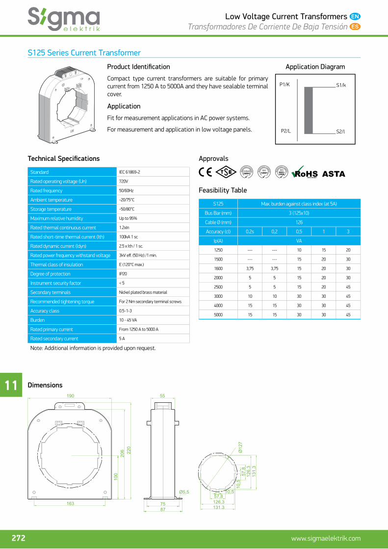
11
272 www.sigmaelektrik.com
Low Voltage Current Transformers Transformadores De Corriente De Baja Tensión
S125 Series Current Transformer
Product Identifi cation
Compact type current transformers are suitable for primary current from 1250 A to 5000A and they have sealable terminal cover.
Application
Fit for measurement applications in AC power systems.
For measurement and application in low voltage panels.
Application Diagram
P1/K
P2/L S2/l
S1/k
Technical Specifi cations
Standard IEC 61869-2
Rated operating voltage (Un) 720V
Rated frequency 50/60Hz
Ambient temperature -20/75°C
Storage temperature -50/80°C
Maximum relative humidity Up to 95%
Rated thermal continuous current 1.2xIn
Rated short-time thermal current (Ith) 100kA 1 sc
Rated dynamic current (Idyn) 2.5 x Ith / 1 sc.
Rated power frequency withstand voltage 3kV eff . (50 Hz) /1 min.
Thermal class of insulation E (120°C max.)
Degree of protection IP20
Instrument security factor < 5
Secondary terminals Nickel plated brass material
Recommended tightening torque For 2 Nm secondary terminal screws
Accuracy class 0.5-1-3
Burden 10 - 45 VA
Rated primary current From 1250 A to 5000 A
Rated secondary current 5 A
Note: Additional information is provided upon request.
Approvals
Feasibility Table
S125 Max. burden against class index (at 5A)
Bus Bar (mm) 3 (125x10)
Cable Ø (mm) 126
Accuracy (cl) 0.2s 0,2 0,5 1 3
Ip(A) VA
1250 --- --- 10 15 20
1500 --- --- 15 20 30
1600 3,75 3,75 15 20 30
2000 5 5 15 20 30
2500 5 5 15 20 45
3000 10 10 30 30 45
4000 15 15 30 30 45
5000 15 15 30 30 45
Dimensions
163
190
100
206 220
131.38775
10,5
126,3
10,5
57,8
57.8
126,3
131,3
Ø127
Ø5,5
55

11
273www.sigmaelektrik.com
Low Voltage Current Transformers Transformadores De Corriente De Baja Tensión
S125 Transformador De Corriente
Presentación Del Producto
Los transformadores de corriente compactos son adecuados para corriente primaria de 1250A hasta 5000A contando con una tapa sellable para el terminal.
Aplicación
Compatible con aplicaciones de medición en sistemas de potencia AC.
La baja tensión es para la medida y aplicación que existe en los paneles.
Diagrama De Conexión
P1/K
P2/L S2/l
S1/k
Características Técnicas
Estándar IEC 61869-2
Corriente nominal de funcionamiento (Un) 720V
Frecuencia nominal 50/60Hz
Temperatura ambiente -20/75°C
Temperatura en carga -50/80°C
Humedad máxima relativa hasta 95%
Corriente nominal constante de funcionamiento 1.2xIn
Corriente nominal de resistencia térmica breve(Ith) 100kA 1 sc
Corriente dinámica nominal (Idyn) 2.5 x Ith / 1 sc.
Tensión nominal de aislamiento de prueba 3kV eff . (50 Hz) /1 min.
Clase de aislamiento E (120°C max.)
Grado de protección IP20
Factor de medida de seguridad < 5
Terminales secundarias Material de bronce revestido de níquel
Par de apriete recomendado 2 Nm para tornillos del terminal secundario
Clase de precisión 0.5-1-3
Potencia nominal 10 - 45 VA
Corriente primaria nominal De 1250 A a 5000 A
Corriente secundaria nominal 5 A
Nota: Se proporcionan otros datos si se requieren.
Certifi cados
Tabla De Viabilidad
S125 Valores máximos de potencia realizable (en 5A)
Barra (mm) 3 (125x10)
Cable Ø (mm) 126
Precisión (cl) 0.2s 0,2 0,5 1 3
Ip(A) VA
1250 --- --- 10 15 20
1500 --- --- 15 20 30
1600 3,75 3,75 15 20 30
2000 5 5 15 20 30
2500 5 5 15 20 45
3000 10 10 30 30 45
4000 15 15 30 30 45
5000 15 15 30 30 45
Dimensiones
163
190
100
206 220
131.38775
10,5
126,3
10,5
57,8
57.8
126,3
131,3
Ø127
Ø5,5
55

11
274 www.sigmaelektrik.com
Low Voltage Current Transformers Transformadores De Corriente De Baja Tensión